
You also want an ePaper? Increase the reach of your titles
YUMPU automatically turns print PDFs into web optimized ePapers that Google loves.
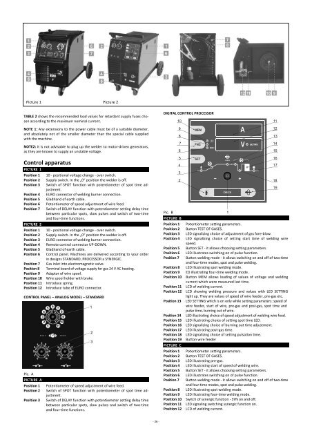
Picture 1 Picture 2<br />
TABLE 2 shows the recommended load values for retardant supply fuses chosen<br />
according to the maximum nominal current.<br />
DIGITAL CONTROL PROCESSOR<br />
NOTE 1: Any extensions to the power cable must be of a suitable diameter,<br />
and absolutely not of the smaller diameter than the special cable supplied<br />
with the machine.<br />
NOTE2: It is not advisable to plug up the welder to motor‐driven generators,<br />
as they are known to supply an unstable voltage.<br />
Control apparatus<br />
PICTURE 1<br />
Position 1<br />
Position 2<br />
Position 3<br />
Position 4<br />
Position 5<br />
Position 6<br />
Position 7<br />
PICTURE 2<br />
Position 1<br />
Position 2<br />
Position 3<br />
Position 4<br />
Position 5<br />
Position 6<br />
Position 7<br />
Position 8<br />
Position 9<br />
Position 10<br />
Position 11<br />
Position 12<br />
10 ‐ positional voltage change ‐ over switch.<br />
Supply switch. In the „0“ position the welder is off.<br />
Switch of SPOT function with potentiometer of spot time adjustment.<br />
EURO connector of welding burner connection.<br />
Gladhand of earth cable.<br />
Potentiometer of speed adjustment of wire feed.<br />
Switch of DELAY function with potentiometer setting delay time<br />
between particular spots, slow pulses and switch of two‐time<br />
and four‐time functions.<br />
10 ‐ positional voltage change ‐ over switch.<br />
Supply switch. In the „0“ position the welder is off.<br />
EURO connector of welding burner connection.<br />
Remote control connector UP‐DOWN.<br />
Gladhand of earth cable.<br />
Control panel. Machines are delivered according to your order<br />
in designs STANDARD, PROCESSOR a SYNERGIC.<br />
Gas inlet into electromagnetic valve.<br />
Terminal board of voltage supply for gas 24 V AC heating.<br />
Adaptor of wire spool.<br />
Wire spool holder with brake.<br />
Introduce spring.<br />
Introduce tube of EURO connector.<br />
CONTROL PANEL – ANALOG MODEL – STANDARD<br />
Pic. A<br />
PICTURE A<br />
Position 1<br />
Position 2<br />
Position 3<br />
Potentiometer of speed adjustment of wire feed.<br />
Switch of SPOT function with potentiometer of spot time adjustment.<br />
Switch of DELAY function with potentiometer setting delay time<br />
between particular spots, slow pulses and switch of two‐time<br />
and four‐time functions.<br />
Pic. B<br />
PICTURE B<br />
Position 1<br />
Position 2<br />
Position 3<br />
Position 4<br />
Position 5<br />
Position 6<br />
Position 7<br />
Position 8<br />
Position 9<br />
Position 10<br />
Position 11<br />
Position 12<br />
Position 13<br />
Position 14<br />
Position 15<br />
Position 16<br />
Position 17<br />
Position 18<br />
Position 19<br />
PICTURE C<br />
Position 1<br />
Position 2<br />
Position 3<br />
Position 4<br />
Position 5<br />
Position 6<br />
Position 7<br />
Position 8<br />
Position 9<br />
Position 10<br />
Position 11<br />
Position 12<br />
Potentiometer setting parameters.<br />
Button TEST OF GASES.<br />
LED signalizing choice of adjustment of gas fore‐blow.<br />
LED signalizing choice of setting start time of welding wire<br />
speed.<br />
Button SET ‐ it allows choosing setting parameters.<br />
LED illustrates switching on of pulse function.<br />
Button welding mode ‐ it allows switching on and off of two‐time<br />
and four‐time modes, spot and pulse welding.<br />
LED illustrating spot welding mode.<br />
ED illustrating four‐time welding mode.<br />
Button MEM allows loading of values of voltage and welding<br />
current which were measured last time.<br />
LCD of welding current.<br />
LCD showing welding pressure and values with LED SETTING<br />
light up. They are values of speed of wire feeder, pre‐gas etc.<br />
LED SETTING which is on only while setting parameters: speed of<br />
wire feeder, start of wire, pre‐gas and post‐gas, spot time and<br />
pulse time, burning out of wire.<br />
LED illustrating choice of speed adjustment of welding wire feed.<br />
LED illustrating choice of setting spot time LED.<br />
LED signalizing choice of burning out time adjustment.<br />
LED illustrating post‐gas time.<br />
LED signalizing choice of setting pulsation time.<br />
Button wire feeder<br />
Potentiometer setting parameters.<br />
Button TEST OF GASES.<br />
LED illustrating pre‐gas.<br />
LED illustrating start of speed of welding wire.<br />
Button SET ‐ it allows choosing setting parameters.<br />
LED illustrates switching on of pulse function.<br />
Button welding mode ‐ it allows switching on and off of two‐time<br />
and four‐time modes, spot and pulse welding.<br />
LED illustrating spot welding mode.<br />
LED illustrating four‐time welding mode.<br />
Switch of synergic function ‐ SYN on and off.<br />
LED signaling switching synergic function on.<br />
LCD of welding current.<br />
‐ 26 ‐