
You also want an ePaper? Increase the reach of your titles
YUMPU automatically turns print PDFs into web optimized ePapers that Google loves.
A return to original parameters synergic adjusted by the producer is done by<br />
the follow‐up pressing and holding the button SYN and then pressing and<br />
releasing the button of wire threading. In such a way it is possible to return<br />
single parameters which have been stored.<br />
A total return of all the pre‐adjusted values to the values set up by the producer<br />
can be done through the function factory configuration.<br />
Using the potentiometer, you shall choose gas type you are going to apply ‐<br />
CO 2 or Ar (marks MIX argon and CO 2 gas in ratio 18 CO 2 and the rest Ar.<br />
Press button SET until you switch on LED diode marked in picture.<br />
Use the potentiometer, thus you shall choose wire diameter SG2 you are<br />
going to use ‐ 0.6 ‐ 0.8 ‐ 1.0 mm.<br />
Approximate thickness of material possible to weld according to current<br />
adjustment will be shown on upper display. Currently adjusted speed of wire<br />
shift will be shown on bottom display, which is changed automatically when<br />
you change positions of voltage switch. Fall or rise in welding capacity is adjustted<br />
with a voltage switch.<br />
Switching function SYNERGIC OFF<br />
Press button SYN. Diode SYN and material thickness will switch off.<br />
Function SYNERGIC is off.<br />
NOTE 1: Shown values of material thickness are only approximate. Thickness<br />
of material can vary according to welding position etc.<br />
NOTE 2: To correct parameter for wire shift, you shall use a potentiometer or<br />
buttons of remote control UP/DOWN.<br />
NOTE 3: Parameters of the program synergic function are designed for copper<br />
coated wire SG2. In order to reach the correct function of the synergic programs,<br />
it is necessary to use quality wire, protective wire, gas and welding<br />
material.<br />
NOTE 4: In order to reach the correct function of the synergic machine it is<br />
necessary to keep prescribed diameters of cables to wire diameters and the<br />
right die otherwise the correct function of the machine is not guaranteed.<br />
Further on, it is necessary to secure quality power supply ‐ 400V, max. +/‐ 5%,<br />
connecting to ground of the welding material (use an earthing clip directly on<br />
the welding material).<br />
RECORGING OWN PARAMETERS OF THE SPEED OF THE WIRE SHIFT INTO<br />
MEMORY<br />
The function of storing parameters is on only if the function synergic is on.<br />
1. Choose the required speed of the wire shift.<br />
2. Press and hold the button SYN and then.<br />
press the button test gas (MEM)<br />
FUNCTION LOGIC ‐ ONLY WITH MACHINES PROCESSOR AND SYNERGIC<br />
Function LOGIC includes a file of simplifying and clarifying points which<br />
present adjusted and currently set values.<br />
If two displays show a few different parameters, it is necessary to simplify<br />
presentation of parameters. Function LOGIC operates just in this way ‐ it makes<br />
everything clear and distinct:<br />
Upper display switches on during welding process only when electronics<br />
makes measurements and shows welding current A (in case there is no<br />
mode SYNERGIC on with machines Synergic. In case there is mode<br />
SYNERGIC on with machines Synergic, display is lit up constantly and only<br />
shown values change). After approx. 7 sec. display switches off automatically<br />
again. Thus electronics increases orientation while reading parameters<br />
during adjustment.<br />
Upper display shows only welding current. When function synergic is on<br />
(only with machines Synergic), upper display shows thickness of material.<br />
Bottom display shows welding voltage while welding and other values ‐<br />
time, speed etc. during adjustment.<br />
LED SETTING will switch off during welding process only when a digital<br />
voltampermeter is used.<br />
LED SETTING is on during welding only when operating staff is adjusting<br />
and changing speed of wire shift with a potentiometer or a remote control<br />
UP/DOWN. As soon as operating staff stops adjustment of a parameter,<br />
LED SETTING will be switched off automatically within 3 sec. and display<br />
shows value of welding voltage.<br />
Recommended adjustment of welding parameters see charts on pg. 56 ‐ 57.<br />
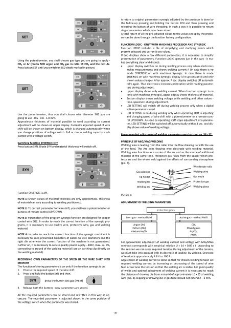
PRINCIPLE OF MIG/MAG WELDING<br />
Welding wire is leading from the roller into the flow drawing tie with the use<br />
of the feed. The Arc joins thawing wire electrode with welding material.<br />
Welding wire functions as a carrier of the arc and as the source of additional<br />
material at the same time. Protective gas flows from the spacer which protects<br />
arc and the whole weld against the effects of surrounding atmosphere<br />
(pic. 4).<br />
Wire feeder rolls<br />
Gas opening<br />
Welding wire<br />
Tip holder<br />
Gas nosle<br />
Welding tip<br />
Protection gas<br />
Welding arc<br />
Welding piece<br />
Picture 4<br />
ADJUSTMENT OF WELDING PARAMETERS<br />
Inert gas ‐ method MIG<br />
Argon (Ar)<br />
Hélium (He)<br />
mixture He/Ar<br />
protective gases<br />
Active gas ‐ method MAG<br />
CO 2<br />
Mixed gases<br />
Ar/CO 2<br />
Ar/O 2<br />
For approximate adjustment of welding current and voltage with MIG/MAG<br />
methods corresponds with empirical relation U = 14 + 0.05 x I . According to<br />
this relation we can asses required tension. During adjustment of the tension,<br />
we must take into account with its decrease at loading by welding. Decrease<br />
of tension is approximately 4.8 V to 100 A.<br />
Adjustment of welding current is done so that for chosen welding tension set<br />
required welding current by increasing or decreasing of the speed of wire<br />
feed or we tune the tension so that the welding arc is stable. For good quality<br />
of welds and optimal adjustment of welding current it is necessary to reach<br />
the distance of drawing die from material of approximately 10 x of welding<br />
wire (pic. 4). Dipping of drawing die in gas tube should not extend 2 – 3 mm.<br />
3. Release both the buttons ‐ new parameters are stored.<br />
All the required parameters can be stored and rewritten in this way as necessary.<br />
The recorded parameter is adjusted always in the same position of<br />
the voltage switch when the parameter was stored.<br />
‐ 30 ‐