Service Manual Analyzer for Combi Screen® 11 SYS urine ... - Alere
Service Manual Analyzer for Combi Screen® 11 SYS urine ... - Alere
Service Manual Analyzer for Combi Screen® 11 SYS urine ... - Alere
You also want an ePaper? Increase the reach of your titles
YUMPU automatically turns print PDFs into web optimized ePapers that Google loves.
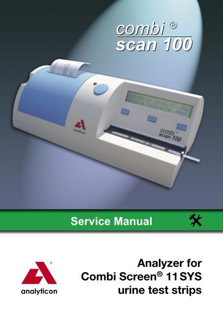
<strong>Service</strong> <strong>Manual</strong><br />
<strong>Analyzer</strong> <strong>for</strong><br />
<strong>Combi</strong> Screen ® <strong>11</strong> <strong>SYS</strong><br />
<strong>urine</strong> test strips
<strong>Service</strong> <strong>Manual</strong> <strong>Combi</strong>Scan 100<br />
2
State: 30.8.2006, Version: 1.2<br />
Contents<br />
<strong>Combi</strong>Scan 100 <strong>Service</strong> <strong>Manual</strong><br />
1. General in<strong>for</strong>mation . . . . . . . . . . . . . . . . . . . . . . . . . . . . . . . . . . . . . . . . . . . . . . . . 4<br />
2. Check of operation. . . . . . . . . . . . . . . . . . . . . . . . . . . . . . . . . . . . . . . . . . . . . . . . . 5<br />
3. Check and repair . . . . . . . . . . . . . . . . . . . . . . . . . . . . . . . . . . . . . . . . . . . . . . . . . . 7<br />
3.1 Check and repair of the power supply . . . . . . . . . . . . . . . . . . . . . . . . . . . . . . 7<br />
3.2 Replacement and repair of the LCD . . . . . . . . . . . . . . . . . . . . . . . . . . . . . . . . 8<br />
3.3 Replacement and repair of the printer. . . . . . . . . . . . . . . . . . . . . . . . . . . . . . . 9<br />
3.4 Handling of the driving unit defect. . . . . . . . . . . . . . . . . . . . . . . . . . . . . . . . . 10<br />
3.5 Handling of the optics defect . . . . . . . . . . . . . . . . . . . . . . . . . . . . . . . . . . . . <strong>11</strong><br />
3.6 Repair of the push button panel and cable defect . . . . . . . . . . . . . . . . . . . . 12<br />
3.7 Handling of SW defect. . . . . . . . . . . . . . . . . . . . . . . . . . . . . . . . . . . . . . . . . . 12<br />
4. Spare parts. . . . . . . . . . . . . . . . . . . . . . . . . . . . . . . . . . . . . . . . . . . . . . . . . . . . . . 13<br />
5. Preparation and required instruments . . . . . . . . . . . . . . . . . . . . . . . . . . . . . . . . . 15<br />
6. Error messages, possible reasons and trouble shooting. . . . . . . . . . . . . . . . . . . 16<br />
7. Assembling instructions. . . . . . . . . . . . . . . . . . . . . . . . . . . . . . . . . . . . . . . . . . . . 17<br />
7.1 Replacement of the assembled upper housing. . . . . . . . . . . . . . . . . . . . . . . 17<br />
7.2 LCD replacement. . . . . . . . . . . . . . . . . . . . . . . . . . . . . . . . . . . . . . . . . . . . . . 20<br />
7.3 Replacement of the push button PCB and the connecting cable. . . . . . . . . 22<br />
7.4 Replacement of printer and panel . . . . . . . . . . . . . . . . . . . . . . . . . . . . . . . . . 24<br />
7.5 Feeding the printer paper . . . . . . . . . . . . . . . . . . . . . . . . . . . . . . . . . . . . . . . 26<br />
Contact:<br />
Analyticon Biotechnologies AG<br />
Am Mühlenberg 10<br />
35104 Lichtenfels - Germany<br />
Phone: +49 (0) 64 54 79 91-0<br />
Fax: +49 (0) 64 54 79 91-71<br />
e-mail: info@analyticon.de<br />
www.analyticon.de<br />
3
<strong>Service</strong> <strong>Manual</strong> <strong>Combi</strong>Scan 100<br />
4<br />
1. General in<strong>for</strong>mation<br />
This service manual describes the control and repair of the <strong>Combi</strong> Scan 100. It is<br />
written <strong>for</strong> use by a well trained service engineer, who is experienced in repairing and<br />
maintaining instruments <strong>for</strong> diagnostic investigations. The operations, which are described<br />
in this manual, should never be carried out by the enduser of the instrument.<br />
The <strong>Combi</strong> Scan 100 is a precise and costly calibrated optical measurement system.<br />
The listed operations below must be accomplished with special attention and precision.<br />
Please take special care to disconnect the device from the power supply if this<br />
is required by the instruction. If spare parts or accessories are needed, it is absolutely<br />
necessary to use only original spare parts <strong>for</strong> this instrument.<br />
Nevertheless, even a well trained service engineer will not be able to do all operations<br />
to get a defective <strong>Combi</strong> Scan 100 working again, because <strong>for</strong> several operations<br />
special equipment is needed. Depending on the problem, it might be necessary to<br />
send the instrument back to Analyticon <strong>for</strong> repair. More detailed in<strong>for</strong>mation can be<br />
found in this manual. If a return of the instrument to Analyticon is recommended by<br />
the manual, please contact Analyticon first to agree on the further steps. Never send<br />
the meter back to Analyticon without any written confirmation of Analyticon to do so.<br />
If repair operations are carried out, they are done in the responsibility of the company<br />
who does the repair. If the meter is opened <strong>for</strong> repair, Analyticon will not take any further<br />
warranty <strong>for</strong> this instrument.
2. Check of operation<br />
Connect the device to the power<br />
supply<br />
A red LED beside the “START”<br />
button lights up.<br />
Yes<br />
The SW version check number<br />
appears on the LCD, then the<br />
display changes <strong>for</strong> the main menu<br />
(Worklist, ChkMeas, Menu)<br />
Yes<br />
Draw paper into the printer (under<br />
the printer cover) (automatic paper<br />
feeding)<br />
Yes<br />
Replace stripholder <strong>for</strong> a check-strip<br />
holder (with grey strip).<br />
Push ”START” button. The device<br />
starts to measure, and prints out the<br />
result. During the measurement a<br />
white LED will flash, according to the<br />
movement of the strip holder, which<br />
can be seen only from sidewards.<br />
Yes<br />
The printer perfectly prints<br />
(without character error)<br />
Yes<br />
Press button under „Worklist”<br />
(mostleft), the display changes <strong>for</strong> a<br />
new window (Wl.Next, Wl.Prev, Print)<br />
Yes<br />
No<br />
No<br />
No<br />
No<br />
No<br />
No<br />
No<br />
No<br />
The power supply feeding of<br />
the device is defected<br />
Error message (E1, E3)<br />
LCD defect or LCD control<br />
defect<br />
Printer defect or printer<br />
control defect<br />
Defect of the driving unit or<br />
the control<br />
Printer defect or printer<br />
control defect<br />
Defective optics or<br />
optics control<br />
Defect of the push<br />
button<br />
No Printer defect or printer<br />
control defect<br />
No Error messages<br />
(E7)<br />
No<br />
Push button defect<br />
<strong>Combi</strong>Scan 100 <strong>Service</strong> <strong>Manual</strong><br />
Check and repair power<br />
supply according section 3.1.<br />
Error message description,<br />
section 5.<br />
Replacement and repair<br />
of LCD, section 3.2.<br />
Replacement and repair<br />
of the printer, section 3.3.<br />
Repair of the driving<br />
unit, section 3.4.<br />
Replacement and repair<br />
of the printer, section 3.3.<br />
Repair of the defect<br />
optics, section 3.5.<br />
Repair of the push button<br />
defect, section 3.6.<br />
Replacement and repair<br />
of the printer, section 3.3.<br />
Error message description,<br />
section 5.<br />
Repair of the push button<br />
defect, section 3.6.<br />
5
<strong>Service</strong> <strong>Manual</strong> <strong>Combi</strong>Scan 100<br />
6<br />
Press button (mostright) under<br />
„Print”. The stored worklist is<br />
printed. The display will change back<br />
to the main menu automatically.<br />
Yes<br />
Press button under the<br />
„ChkMeas” (middle). “Check mode<br />
measurement” is diplayd and check<br />
measurement is per<strong>for</strong>med.<br />
The device prints out the result of<br />
the check measurement. „Valid<br />
check” or „Invalid check”.<br />
Then returns to the main menu<br />
automatically.<br />
Yes<br />
Press the ”START” button. The<br />
display goes back to the main menu.<br />
Yes<br />
Press button under „Menu”<br />
(rightmost). Further MENU items<br />
are displayed (Setup, MeasMode,<br />
Memory).<br />
Yes<br />
Main units of the device are<br />
operating proper. Different<br />
parameters should be checked<br />
or set (i.e. date, time, language)<br />
according to the user‘s manual.<br />
Yes<br />
Visual test: visible damages of the<br />
upper housing, printer cover, plastic<br />
push buttons, plexi plate.<br />
No<br />
No<br />
No<br />
No<br />
No<br />
No<br />
No<br />
No<br />
Push button defect<br />
SW error<br />
Error messages<br />
(E7)<br />
Push button defect<br />
SW error<br />
SW error<br />
Error messages<br />
SW error<br />
No Problem unsolvable by the<br />
service<br />
No Replacement of the<br />
assembled upper housing.<br />
See section 5.<br />
Repair of the push button<br />
defect, section 3.6.<br />
SW error handling,<br />
section 3.7.<br />
Error message description,<br />
section 5.<br />
Repair of the push button<br />
defect, section 3.6.<br />
SW error SW error handling,<br />
section 3.7.<br />
SW error handling,<br />
section 3.7.<br />
Error message description,<br />
section 5.<br />
SW error handling,<br />
section 3.7.<br />
The equipment must be<br />
returned <strong>for</strong> repair.
3. Check and repair<br />
3.1 Check and repair of the power supply<br />
<strong>Combi</strong>Scan 100 <strong>Service</strong> <strong>Manual</strong><br />
Warning! Never open power supply! If the power supply damaged replace it! Also<br />
replace power cord if any damage is observable!<br />
If there is no visual damage on power supply or<br />
power cord connect the equipment to the power<br />
supply!<br />
CHECK:<br />
1. whether there is a power is on<br />
2. the plug<br />
3. the power cord<br />
4. connections.<br />
5. Measure the output voltage of the equipment!<br />
REPAIR:<br />
1. Set back the line voltage! (Replacement of the fuse!)<br />
2. Another plug must be used!<br />
3. Replacement of the adapter cable!<br />
4. Replacement of the adapter!<br />
If it is less than 7VDC, replace the adapter!<br />
If the defect is still existing and the equipment does<br />
not operate, or such component got damaged,<br />
which cannot be replaced:<br />
the equipment must be returned <strong>for</strong> repair!<br />
7
<strong>Service</strong> <strong>Manual</strong> <strong>Combi</strong>Scan 100<br />
8<br />
3.2. Replacement and repair of the LCD<br />
The LCD does not or not properly operate.<br />
The displayed characters are incomplete<br />
CHECK:<br />
1. Check the flex cable of the LCD!<br />
Did it slip out from the socket?<br />
2. Check the LCD<br />
Connect a new LCD without installing it and<br />
check whether the defect is eliminated.<br />
REPAIR<br />
1. Adjust the connection<br />
2. Replace LCD. (see section 7.2.)<br />
If the defect is still exists and the display does not<br />
operate, the LCD control got damaged.<br />
the equipment must be returned <strong>for</strong> repair!
3.3. Replacement and repair of the printer<br />
Defects arisen during printing:<br />
• No printing<br />
• Wrong characters are printed<br />
CHECK:<br />
1. Check the printing paper<br />
• Is there paper in the printer?<br />
• Is the paper stuck into the equipment?<br />
2. Check the printer<br />
• Check and move the plugs on the panel<br />
(slipped off or contact defect?<br />
• Check the flexible cable of the printer (did it<br />
slip out?).<br />
• Connect a new printer (section 7.4.) without<br />
installing it, feed the printer by paper and<br />
check whether printing is correct.<br />
<strong>Combi</strong>Scan 100 <strong>Service</strong> <strong>Manual</strong><br />
REPAIR<br />
1. Repair of the printer paper defect.<br />
Put new paper into the printer and/or insert it<br />
properly<br />
• Take out the stuck paper and insert it properly.<br />
2. Repair of the printer defect.<br />
In case of no socket defect and it cannot be<br />
eliminated by moving it, the printer and the panel<br />
must be replaced.<br />
• Pull out the flexible cables of the printer from<br />
the socket. Check the connector ends (damage,<br />
break, dirt), then plug it again. Check the<br />
operation of the printer.<br />
• If the printing is correct when using the new<br />
printer, replace it.<br />
• If the defect still exists using the new printer,<br />
the equipment must be returned <strong>for</strong> repair.<br />
9
<strong>Service</strong> <strong>Manual</strong> <strong>Combi</strong>Scan 100<br />
10<br />
3.4. Handling of the defect driving unit<br />
Driving unit defects.:<br />
• The motor does not operate.<br />
• The strip holder cannot be pushed in.<br />
• It pushes the strip holder out.<br />
• The strip holder is stuck (it moves only inward).<br />
CHECK:<br />
2. Insert a strip holder into the equipment and<br />
connect the power supply to the equipment,<br />
push the „START“ button.<br />
REPAIR:<br />
1. If the defect, arisen during the check or the<br />
operation, does not cease:<br />
• by the replacement of the firmware key (section<br />
7.1.)<br />
• or by the replacement of the strip holder,<br />
• than by a restart<br />
the equipment must be returned <strong>for</strong> repair!
3.5. Handling of the optics defect<br />
Optics unit defects.<br />
• The LEDs do not light.<br />
• The CCD does not detect.<br />
• Optocoupler does not operate.<br />
CHECK:<br />
3. Insert a strip holder into the equipment and<br />
connect the power supply, push „START“<br />
button. Watching it from sidewards there<br />
must be a white light flashing up according<br />
to the rhythm of the movement of the strip<br />
holder!<br />
<strong>Combi</strong>Scan 100 <strong>Service</strong> <strong>Manual</strong><br />
REPAIR:<br />
2. If the defects arisen during the check or the<br />
operation of the equipment do not cease<br />
• by the replacement of firmware key (section <strong>11</strong>.)<br />
• then by a restart,<br />
the equipment must be returned <strong>for</strong> repair!<br />
<strong>11</strong>
<strong>Service</strong> <strong>Manual</strong> <strong>Combi</strong>Scan 100<br />
12<br />
3.6. Repair of the push button panel and cable defect<br />
Push button panel and cable defects.<br />
• LED does not light.<br />
• Switches on the PCB do not operate<br />
• Cable is torn, the soldering came off.<br />
CHECK:<br />
4. Insert a strip holder into the equipment and<br />
connect the power supply, push „START“<br />
button. Measurement has to be started.<br />
3.7. Handling of SW defect<br />
REPAIR:<br />
5. Replace start- and push button PCB with cable<br />
(UCP-4454-1) with the spare one.<br />
6. If the defect still exists,<br />
the equipment must be returned <strong>for</strong> repair.<br />
If defects, arisen during check or operation, do not cease by the replacement of the<br />
firmware key and restart.<br />
The equipment must be returned <strong>for</strong> repair!
4. Spare parts<br />
Order Article<br />
No.<br />
<strong>Combi</strong>Scan 100 <strong>Service</strong> <strong>Manual</strong><br />
Denomination Content Figure<br />
UCP-4451-1 Assembled LCD, with<br />
frame and plastic<br />
shim.<br />
The plastic shim is<br />
only at later models.<br />
UCP-4452-1 Assembled printer,<br />
with panel<br />
UCP-4453-1 Assembled upper<br />
housing<br />
UCP-4454-1 Spare assembled<br />
start- and push<br />
button PCB with<br />
cable<br />
1ASA7V1A Power supply type<br />
SA125A-0735U-S<br />
Display, LCD bear<br />
frame<br />
Assembly: section 7.2<br />
Printer, panel, cable<br />
Assembly: section 7.4<br />
Upper housing, LCD<br />
front panel, printer<br />
cover, push buttons<br />
Assembly: section 7.1<br />
Start-and push button<br />
panel, cables, plugs<br />
Assembly: section 7.3<br />
612EPL19 Printer paper Feeding: section 7.5<br />
13
<strong>Service</strong> <strong>Manual</strong> <strong>Combi</strong>Scan 100<br />
14<br />
Order Article<br />
No.<br />
Denomination Content Figure<br />
352USBAB USB cable_type_a-b/1.8 m<br />
35200303 Power cord<br />
UCP-4404-1 Assembled strip holder <strong>for</strong><br />
<strong>Combi</strong>Scan100<br />
UCP-4405-1 Firmware<br />
UCP-4414-1 Assembled check-strip<br />
holder<br />
UCP-9201-1 User‘s manual<br />
UCP-9202-1 CD<br />
Assembled strip<br />
holder with stuck<br />
test strip
<strong>Combi</strong>Scan 100 <strong>Service</strong> <strong>Manual</strong><br />
5. Preparation, required instruments, auxiliary material,<br />
labour safety regulations<br />
Cross-grooved screwdriver PH1<br />
Cross-grooved screwdriver PZ1<br />
Straight grooved screwdriver size 4<br />
There are no other labour safety regulations different from the general ones concerning<br />
the checking, assembly processes listed in this present <strong>Service</strong> <strong>Manual</strong>.<br />
No dangerous material is used.<br />
15
<strong>Service</strong> <strong>Manual</strong> <strong>Combi</strong>Scan 100<br />
16<br />
6. Error messages, possible reasons and trouble shooting methods<br />
Error<br />
code<br />
Denomination of<br />
the error<br />
E1 Error in the driving of<br />
the strip holder (“0”<br />
position detection<br />
error).<br />
E3 Firmware (key-chip)<br />
error.<br />
E4 Communication error<br />
(defect of the serial<br />
port or cable).<br />
E5 “Worklist” download<br />
error<br />
E6 “Worklist full”. The<br />
memory is fully<br />
loaded.<br />
E7 Printer paper run out<br />
or is missing.<br />
W1 No data in the<br />
memory to be<br />
transferred.<br />
Reasons <strong>for</strong> the error Trouble shooting<br />
The optical sensor<br />
does not detect the<br />
existence of the<br />
stripholder. Maybe no<br />
stripholder is inserted.<br />
There is no firmware<br />
inserted or firmware<br />
damaged.<br />
The serial port/plug<br />
or cable are defective<br />
or the connected unit<br />
(PC) doesn‘t work.<br />
Block, longer than 13<br />
characters, or patient<br />
ID block not loaded up<br />
to 13 characters<br />
Work list memory is<br />
fully loaded.<br />
Replacement of the strip<br />
holder, if the error is<br />
still existing the device<br />
should be returned <strong>for</strong><br />
service.<br />
Insert firmware of the right<br />
version into the equipment<br />
to its determined place. If<br />
the error is still existing<br />
the device should be<br />
returned <strong>for</strong> service.<br />
All connections should<br />
be fitted. Try to connect<br />
to an other device (PC). If<br />
the error is still existing<br />
the device should be<br />
returned <strong>for</strong> service.<br />
Load the patient ID block<br />
up to 13 characters. Check<br />
communication with the<br />
connecting device. If<br />
the error is still existing<br />
the device should be<br />
returned <strong>for</strong> service.<br />
Data down load from the<br />
memory, clear memory.<br />
Feed the equipment with<br />
paper. section 7.5.<br />
Fill up the memory by<br />
some measurements and<br />
try again. If the error is<br />
still existing the device<br />
should be returned <strong>for</strong><br />
service.
7. Assembling instructions<br />
<strong>Combi</strong>Scan 100 <strong>Service</strong> <strong>Manual</strong><br />
7.1 Replacement of the assembled upper housing (UCP-4453-1)<br />
Operation Figure<br />
7.1.1. Disconnect power supply.<br />
Remove firmware (under the<br />
printer cover).<br />
Unscrew the screw<br />
(1 pc PT KA 22x8).<br />
7.1.2. Turn the equipment upsidedown.<br />
7.1.3. Unscrew the screws (4 or 5 pcs<br />
PT KA 30x8).<br />
17
<strong>Service</strong> <strong>Manual</strong> <strong>Combi</strong>Scan 100<br />
18<br />
Operation Figure<br />
7.1.4. Turn back the equipment.<br />
7.1.5. Lift the upper case (upright),<br />
tilt it backward in 180 degree.<br />
Note the position of the cable.<br />
7.1.6. Unscrew the two screws (PT<br />
KA 25x6) which fix the start<br />
button PCB, pull out the LED<br />
assembled onto the PCB from<br />
the housing.<br />
7.1.7. Put aside the upper case,<br />
prepare the new one.<br />
7.1.8. Fit LED into the housing (pay<br />
attention to the PCB position),<br />
screw the two screw in (2 pcs<br />
PT KA 25x6).
Operation Figure<br />
7.1.9. Turn the upper housing onto<br />
the bottom case and holding<br />
it at right angles arrange the<br />
cables (they must not jam<br />
between the two parts).<br />
7.1.10. Turn the equipment upside<br />
down.<br />
7.1.<strong>11</strong>. Screw the screws in (4 or 5 pcs<br />
PT KA 30x8, 1 pc PT KA 22x8).<br />
7.1.12. Turn the equipment back.<br />
7.1.13. Insert the firmware into its<br />
place.<br />
<strong>Combi</strong>Scan 100 <strong>Service</strong> <strong>Manual</strong><br />
Figure according to 7.1.2.<br />
Figure according to point 7.1.3.<br />
Figure according to point 7.1.1.<br />
19
<strong>Service</strong> <strong>Manual</strong> <strong>Combi</strong>Scan 100<br />
20<br />
7.2. Replacement of the LCD (UCP-4451-1)<br />
Operation Figure<br />
7.2.1. Disassemble the equipment. According to points 7.1.1 – 7.1.5.<br />
7.2.2. Relase connector fixture<br />
on both end by pressing in<br />
direction as the red arrow<br />
shows.<br />
Pull out the flexibile cable from<br />
the connector.<br />
7.2.3. Unscrew the 2 screws which fix<br />
the button PCB to the frame.<br />
Remove plastic shim.<br />
7.2.4. Unscrew the screws of the LCD<br />
frame (3 pcs PT KA 25x8.)
Operation Figure<br />
7.2.5. Replace the frame, assembled<br />
with LCD, fit it to its position.<br />
7.2.6. Screw in the 3 pcs screws<br />
which fix the LCD bear frame<br />
(PTKA 25x8).<br />
7.2.7. Screw in the 2 pcs screws<br />
which fix the push button panel<br />
to the LCD bear frame (PTKA<br />
25x8)<br />
7.2.8. Connect flexibile cable. First<br />
insert cable into the slot of<br />
the connector. Then fix the<br />
connection by pressing both<br />
end of connector in diraction<br />
shown by the red arrow.<br />
<strong>Combi</strong>Scan 100 <strong>Service</strong> <strong>Manual</strong><br />
Figure according to point 7.2.4.<br />
Figure according to point 7.2.3.<br />
7.2.9. Assemble the equipment. According to 7.1.9 – 7.1.13<br />
21
<strong>Service</strong> <strong>Manual</strong> <strong>Combi</strong>Scan 100<br />
22<br />
7.3 Replacement of the push button PCB and the connecting cable<br />
(UCP-4454-1)<br />
Operation Figure<br />
7.3.1. Disassemble the equipment. According to points 7.1.1 – 7.1.6.<br />
7.3.2. Put aside the upper housing.<br />
7.3.3. Unscrew the 2 pcs screw which<br />
fix the push button panel to the<br />
LCD frame.<br />
Remove plastic shim.<br />
7.3.4. Note the position of the cables.<br />
Disconnect the cable (10p).<br />
(Put aside the panels and the<br />
cables.)<br />
7.3.5. Connect the connector of the<br />
cable of the spare assembled<br />
push button panels to the<br />
connector of the “main” panel.<br />
7.3.6. Screw in the 2 pcs screws<br />
which fixes the printer panel to<br />
the LCD frame. (2pcs PT KA<br />
25x8)<br />
Figure according to point 7.3.4<br />
According to the point 7.3.3
Operation Figure<br />
7.3.7. Insert the LED of the Start<br />
button into the housing (take<br />
care of the panel position),<br />
screw in the two screws fixing<br />
the panel (2 pcs PT KA 25x6)<br />
<strong>Combi</strong>Scan 100 <strong>Service</strong> <strong>Manual</strong><br />
7.3.8. Assemble the equipment. According to 7.1.9. - 7.1.13.<br />
23
<strong>Service</strong> <strong>Manual</strong> <strong>Combi</strong>Scan 100<br />
24<br />
7.4. Replacement of printer and panel (UCP-4452-1)<br />
Operation Figure<br />
7.4.1. Disassemble the equipment According to 7.1.1. – 7.1.5.<br />
7.4.2. Place the upper housing<br />
behind the lower housing.<br />
7.4.3. Unscrew the 4 screws which fix<br />
the printer and the PCB, lift the<br />
panel.<br />
7.4.4. Disconnect both connectors<br />
from the printer PCB. Note the<br />
directions and routing of the<br />
cables! (2p and 16p)
<strong>Combi</strong>Scan 100 <strong>Service</strong> <strong>Manual</strong><br />
Operation Figure<br />
7.4.5. Connect the cables to the<br />
spare assembled printer panel.<br />
(2p and 16p)<br />
Figure according to point 7.4.4.<br />
7.4.6. Place the printer panel onto its<br />
location. Screw in the two short<br />
screws (PTKA 22x6) into the<br />
front holes, then screw in the<br />
two longer screws (PTKA 22x8)<br />
onto the rear.<br />
7.4.7. Assemble the equipment According to the 7.1.9. – 7.1.13.<br />
25
<strong>Service</strong> <strong>Manual</strong> <strong>Combi</strong>Scan 100<br />
26<br />
7.5. Feeding the printer paper (612EPL19)<br />
Operation Figure<br />
7.5.1 Open printer cover, insert paper<br />
roll into the holder.<br />
7.5.2 Insert the end of the printer<br />
paper into the slot located at<br />
the rear of the printer.<br />
After it paper feeding goes on<br />
automatically if the device is<br />
turned on.<br />
The edge of the paper must not<br />
be torn or uneven.<br />
7.5.3 Close the printer cover, stitch<br />
the end of the paper through<br />
the slot of the cover.


