Ditch Witch 1820 Operators Manual - Ben's Rental and Sales
Ditch Witch 1820 Operators Manual - Ben's Rental and Sales
Ditch Witch 1820 Operators Manual - Ben's Rental and Sales

Create successful ePaper yourself
Turn your PDF publications into a flip-book with our unique Google optimized e-Paper software.
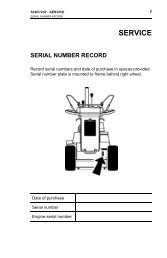
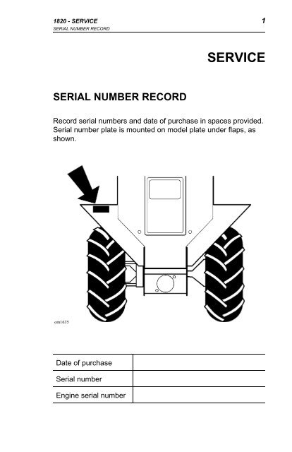
<strong>1820</strong> - SERVICE 1<br />
SERIAL NUMBER RECORD<br />
SERIAL NUMBER RECORD<br />
SERVICE<br />
Record serial numbers <strong>and</strong> date of purchase in spaces provided.<br />
Serial number plate is mounted on model plate under flaps, as<br />
shown.<br />
om1635<br />
Date of purchase<br />
Serial number<br />
Engine serial number
2 <strong>1820</strong> - SERVICE<br />
SUPPORT PROCEDURE<br />
SUPPORT PROCEDURE<br />
Notify your dealer immediately of any malfunction or failure of<br />
<strong>Ditch</strong> <strong>Witch</strong> equipment.<br />
Always give model, serial number, <strong>and</strong> approximate date of<br />
equipment purchase. This information should be recorded <strong>and</strong><br />
placed on file by owner at time of purchase.<br />
Return damaged parts to dealer for inspection <strong>and</strong> warranty<br />
consideration.<br />
Order genuine <strong>Ditch</strong> <strong>Witch</strong> replacement parts from your<br />
authorized ditch <strong>Witch</strong> dealer. Use of another manufacturer’s<br />
parts may void warranty.<br />
RESOURCES<br />
Publications<br />
Contact your <strong>Ditch</strong> <strong>Witch</strong> dealer for publications <strong>and</strong> videos<br />
covering safety, operation, service, <strong>and</strong> repair of your equipment.<br />
<strong>Ditch</strong> <strong>Witch</strong> Training<br />
For information about on-site, individualized training, contact your<br />
<strong>Ditch</strong> <strong>Witch</strong> dealer.
<strong>1820</strong> - FOREWORD 3<br />
FOREWORD<br />
This manual is an important part of your equipment. It provides<br />
safety information <strong>and</strong> operation instructions to help you use <strong>and</strong><br />
maintain your <strong>Ditch</strong> <strong>Witch</strong> equipment.<br />
Read this manual before using your equipment. Keep it with the<br />
equipment at all times for future reference. If you sell your<br />
equipment, be sure to give this manual to the new owner.<br />
If you need a replacement copy, contact your <strong>Ditch</strong> <strong>Witch</strong> dealer.<br />
If you need assistance in locating a dealer, visit our website at<br />
www.ditchwitch.com or write to the following address:<br />
The Charles Machine Works, Inc.<br />
Attn: Marketing Department<br />
PO Box 66<br />
Perry, OK 73077-0066<br />
USA<br />
The descriptions <strong>and</strong> specifications in this manual are subject to<br />
change. The Charles Machine Works, Inc. reserves the right to<br />
improve equipment. Some product improvements may have<br />
taken place after this manual was published. For the latest<br />
information on <strong>Ditch</strong> <strong>Witch</strong> equipment, see your <strong>Ditch</strong> <strong>Witch</strong><br />
dealer.<br />
Thank you for buying <strong>and</strong> using <strong>Ditch</strong> <strong>Witch</strong> equipment.
4 <strong>1820</strong> - FOREWORD<br />
Operator's <strong>Manual</strong><br />
<strong>1820</strong><br />
Issue Number 5.2/OP-9/04<br />
Part Number 054-485<br />
Copyright 1994, 1995, 2003, 2004<br />
by The Charles Machine Works, Inc.,<br />
Perry, Oklahoma, 73077-0066.<br />
, <strong>Ditch</strong> <strong>Witch</strong>, CMW, AutoCrowd,<br />
Modularmatic, Jet Trac, Roto <strong>Witch</strong>, Subsite, Fluid Miser, Perma-<br />
Soil, Power Pipe, Super <strong>Witch</strong>, Super <strong>Witch</strong> II, Pierce Airrow, The<br />
Underground, <strong>and</strong> The Underground Authority Worldwide are<br />
registered trademarks of The Charles Machine Works, Inc.
<strong>1820</strong> - CONTENTS 5<br />
CONTENTS<br />
SERVICE . . . . . . . . . . . . . . . . . . . . . . . . . . . . . . . . . . . . . . . 1<br />
Serial Number Record . . . . . . . . . . . . . . . . . . . . . . . . . 1<br />
Support Procedure . . . . . . . . . . . . . . . . . . . . . . . . . . . . 2<br />
Resources . . . . . . . . . . . . . . . . . . . . . . . . . . . . . . . . . . 2<br />
FOREWORD . . . . . . . . . . . . . . . . . . . . . . . . . . . . . . . . . . . . 3<br />
OVERVIEW . . . . . . . . . . . . . . . . . . . . . . . . . . . . . . . . . . . . . 9<br />
CONTROLS . . . . . . . . . . . . . . . . . . . . . . . . . . . . . . . . . . . . 11<br />
Console . . . . . . . . . . . . . . . . . . . . . . . . . . . . . . . . . . . 11<br />
Descriptions . . . . . . . . . . . . . . . . . . . . . . . . . . . . . . . . 12<br />
SAFETY . . . . . . . . . . . . . . . . . . . . . . . . . . . . . . . . . . . . . . . 19<br />
Underground Hazards . . . . . . . . . . . . . . . . . . . . . . . . 20<br />
Emergency Procedures . . . . . . . . . . . . . . . . . . . . . . . 20<br />
Safety Alert Classifications . . . . . . . . . . . . . . . . . . . . . 22<br />
Safety Alerts . . . . . . . . . . . . . . . . . . . . . . . . . . . . . . . . 23<br />
TRANSPORTATION . . . . . . . . . . . . . . . . . . . . . . . . . . . . . 29<br />
Lifting . . . . . . . . . . . . . . . . . . . . . . . . . . . . . . . . . . . . . 29<br />
Hauling . . . . . . . . . . . . . . . . . . . . . . . . . . . . . . . . . . . . 30<br />
Loading . . . . . . . . . . . . . . . . . . . . . . . . . . . . . . . . . . . 31<br />
Towing . . . . . . . . . . . . . . . . . . . . . . . . . . . . . . . . . . . . 33
6 <strong>1820</strong> - CONTENTS<br />
OPERATION . . . . . . . . . . . . . . . . . . . . . . . . . . . . . . . . . . . 35<br />
Inspect Machine . . . . . . . . . . . . . . . . . . . . . . . . . . . . 35<br />
Startup . . . . . . . . . . . . . . . . . . . . . . . . . . . . . . . . . . . . 37<br />
Driving . . . . . . . . . . . . . . . . . . . . . . . . . . . . . . . . . . . . 38<br />
TRENCHING ATTACHMENT . . . . . . . . . . . . . . . . . . . . . . 39<br />
Operating Tips . . . . . . . . . . . . . . . . . . . . . . . . . . . . . . 40<br />
DRILLING ATTACHMENT . . . . . . . . . . . . . . . . . . . . . . . . 43<br />
Drilling Attachment Control Descriptions . . . . . . . . . . 44<br />
Prepare Jobsite <strong>and</strong> Equipment . . . . . . . . . . . . . . . . 45<br />
Drill . . . . . . . . . . . . . . . . . . . . . . . . . . . . . . . . . . . . . . 47<br />
Add Rod . . . . . . . . . . . . . . . . . . . . . . . . . . . . . . . . . . 49<br />
Backream . . . . . . . . . . . . . . . . . . . . . . . . . . . . . . . . . 49<br />
Disassemble Joints . . . . . . . . . . . . . . . . . . . . . . . . . . 50<br />
Optional Equipment . . . . . . . . . . . . . . . . . . . . . . . . . . 50<br />
LUBRICATION . . . . . . . . . . . . . . . . . . . . . . . . . . . . . . . . . 51<br />
Schedule . . . . . . . . . . . . . . . . . . . . . . . . . . . . . . . . . . 52<br />
Engine Oil . . . . . . . . . . . . . . . . . . . . . . . . . . . . . . . . . 54<br />
Hydraulic Oil . . . . . . . . . . . . . . . . . . . . . . . . . . . . . . . 55<br />
Pivot Tube . . . . . . . . . . . . . . . . . . . . . . . . . . . . . . . . . 57<br />
Trail Wheel Bearing . . . . . . . . . . . . . . . . . . . . . . . . . . 57<br />
Cross <strong>and</strong> Bearing . . . . . . . . . . . . . . . . . . . . . . . . . . 57<br />
Reducer Boxes . . . . . . . . . . . . . . . . . . . . . . . . . . . . . 58
<strong>1820</strong> - CONTENTS 7<br />
MAINTENANCE . . . . . . . . . . . . . . . . . . . . . . . . . . . . . . . . . 61<br />
Schedule . . . . . . . . . . . . . . . . . . . . . . . . . . . . . . . . . . 62<br />
Fuel . . . . . . . . . . . . . . . . . . . . . . . . . . . . . . . . . . . . . . 64<br />
Battery . . . . . . . . . . . . . . . . . . . . . . . . . . . . . . . . . . . . 66<br />
Air Filter . . . . . . . . . . . . . . . . . . . . . . . . . . . . . . . . . . . 68<br />
Cooling System . . . . . . . . . . . . . . . . . . . . . . . . . . . . . 70<br />
Belts . . . . . . . . . . . . . . . . . . . . . . . . . . . . . . . . . . . . . . 71<br />
Headshaft Sprocket Bolts . . . . . . . . . . . . . . . . . . . . . . 71<br />
Wheels <strong>and</strong> Tires . . . . . . . . . . . . . . . . . . . . . . . . . . . . 71<br />
Trenching Attachment . . . . . . . . . . . . . . . . . . . . . . . . 73<br />
SPECIFICATIONS . . . . . . . . . . . . . . . . . . . . . . . . . . . . . . . 77
8 <strong>1820</strong> - CONTENTS
<strong>1820</strong> - OVERVIEW 9<br />
OVERVIEW<br />
The <strong>Ditch</strong> <strong>Witch</strong> <strong>1820</strong> is a self-propelled, walk-along,<br />
hydraulically steered, two-wheel drive trencher designed to dig in<br />
a variety of soils <strong>and</strong> move large volumes of dirt in a short time.<br />
With an optional drilling unit attached, it is also designed to drill<br />
short distances.<br />
om1641x<br />
A. Control Panel<br />
B. Restraint Bar<br />
C. Digging Chain/Boom<br />
D. Trail Wheel<br />
E. Drive Wheel
10 <strong>1820</strong> - OVERVIEW
<strong>1820</strong> - CONTROLS 11<br />
CONSOLE<br />
CONSOLE<br />
CONTROLS<br />
Gasoline Engine Diesel Engine<br />
om1783<br />
1. Axle lock (blue)<br />
2. Boom control (green)<br />
3. Oil pressure indicator<br />
4. Operator presence switch<br />
(red)<br />
5. Speed/Direction control<br />
(orange)<br />
6. Hydraulic pump control<br />
(orange)<br />
7. Roto <strong>Witch</strong> control<br />
(optional)<br />
8. Digging chain control<br />
(yellow)<br />
om1783a<br />
9. Ignition switch<br />
10. Voltmeter<br />
11. Hourmeter<br />
12. Choke (gas only)<br />
13. Throttle<br />
14. Battery disconnect switch<br />
(diesel only)<br />
15. Water temperature gauge<br />
(diesel only)<br />
16. Glow plug indicator (diesel<br />
only)
12 <strong>1820</strong> - CONTROLS<br />
DESCRIPTIONS<br />
Axle Lock (blue)<br />
This lever locks axle (two-wheel drive)<br />
or unlocks axle (one-wheel drive).<br />
• Pull to unlock axle. Use unlocked<br />
axle to turn trencher.<br />
• Push to lock axle. Use locked axle<br />
for straight trenching.<br />
Boom Control (green)<br />
This lever raises or lowers digging<br />
boom. Can be used only when engine<br />
is running.<br />
• Push to lower.<br />
• Pull to raise.<br />
Oil Pressure Indicator<br />
This light indicates low oil pressure.<br />
Light will come on briefly when engine<br />
is started. If light comes on when<br />
engine is running:<br />
• Turn engine off.<br />
• Check oil level.<br />
• Check for leaks before starting<br />
engine.<br />
ic1034<br />
ic1033<br />
om1008.pcx<br />
CONSOLE
<strong>1820</strong> - CONTROLS 13<br />
CONSOLE<br />
Operator Presence Switch<br />
(red)<br />
This button prevents machine from<br />
running when digging or driving unless<br />
operator is pressing switch. Operator<br />
presence switch is on top of speed/<br />
direction control.<br />
Speed/Direction Control<br />
(orange)<br />
This lever controls unit speed <strong>and</strong><br />
direction.<br />
om1014.pcx<br />
• Push to move toward digging<br />
boom.<br />
• Pull to move toward operator<br />
ic0029h<br />
position.<br />
• To go faster in either direction,<br />
move control farther from center (neutral) position.<br />
• To stop, return to neutral position.<br />
• To turn, move control to left or right while it is in forward,<br />
neutral, or reverse position.
14 <strong>1820</strong> - CONTROLS<br />
Hydraulic Pump Control<br />
(orange)<br />
This lever is used to help start cold<br />
engine.<br />
• Push to engage<br />
• Pull to disengage.<br />
Roto <strong>Witch</strong> Control<br />
This lever controls optional boring<br />
attachment. Refer to Roto <strong>Witch</strong><br />
Operator's <strong>Manual</strong> for additional<br />
information.<br />
• Push to rotate clockwise.<br />
• Pull to rotate counterclockwise.<br />
Digging Chain Control (yellow)<br />
This lever controls digging chain action<br />
<strong>and</strong> speed.<br />
• Push to start digging chain.<br />
• Pull to stop digging chain.<br />
ic1036<br />
ic1085b<br />
ic1035a<br />
CONSOLE
<strong>1820</strong> - CONTROLS 15<br />
CONSOLE<br />
Ignition Switch<br />
This switch is used to start engine.<br />
Gasoline Engines:<br />
• Insert key <strong>and</strong> turn it clockwise to<br />
start position (C).<br />
• When engine starts, release key. It<br />
ic1084<br />
will return to on position (B).<br />
• If engine does not start or is killed, turn switch to off position<br />
(A), then restart.<br />
Diesel Engines:<br />
• Insert key <strong>and</strong> turn it clockwise to on position (B). Glow plug<br />
indicator will light as engine heats.<br />
• When glow plug indicator goes out, turn key to start position<br />
(C).<br />
• When engine starts, release key. It will return to on position<br />
(B).<br />
• If engine does not start or is killed, turn switch to off position<br />
(A), then restart.<br />
Voltmeter<br />
This gauge measures voltage in<br />
electric system. Reading should be<br />
between 12 <strong>and</strong> 15 volts with engine<br />
running. If not, stop engine <strong>and</strong><br />
investigate.<br />
om1132.pcx
16 <strong>1820</strong> - CONTROLS<br />
Hourmeter<br />
This gauge records operating time. Use<br />
to schedule lubrication <strong>and</strong><br />
maintenance.<br />
Choke (gas only)<br />
This knob helps start cold engine.<br />
• Pull Choke before starting.<br />
• Push Choke in completely when<br />
engine has warmed.<br />
Throttle<br />
This lever regulates engine speed.<br />
• Push toward rabbit to increase<br />
engine speed.<br />
• Pull toward turtle to slow engine.<br />
om1132.pcx<br />
om1011.pcx<br />
ic1032<br />
CONSOLE
<strong>1820</strong> - CONTROLS 17<br />
CONSOLE<br />
Water Temperature Gauge<br />
(diesel only)<br />
This gauge displays temperature of<br />
water in cooling system.<br />
Glow Plug Indicator<br />
(diesel only)<br />
This indicator lights when glow plug is<br />
heating.<br />
NOTICE: Do not turn ignition switch to<br />
start until glow plug indicator goes out.<br />
For complete starting instructions, see<br />
OPERATION.<br />
om1463.pcx<br />
ic0026h
18 <strong>1820</strong> - CONTROLS<br />
Battery Disconnect<br />
Use for shut-off, when servicing, <strong>and</strong><br />
during long-term storage.<br />
Battery disconnect is optional on<br />
gasoline engines (top illustration) <strong>and</strong><br />
st<strong>and</strong>ard on diesel engines (bottom<br />
illustration).<br />
Gasoline engine:<br />
• Turn clockwise to connect battery<br />
power.<br />
• Turn counterclockwise to<br />
disconnect battery power.<br />
Diesel engine:<br />
• Turn counterclockwise to connect<br />
battery power.<br />
• Turn clockwise to disconnect<br />
battery power.<br />
om1749<br />
om1486.pcx<br />
CONSOLE
<strong>1820</strong> - SAFETY 19<br />
CONSOLE<br />
SAFETY<br />
Follow these guidelines before operating any jobsite equipment:<br />
• Complete proper training <strong>and</strong> read operator’s manual before<br />
using equipment.<br />
• Contact your local One-Call or utility company. Have all<br />
underground lines <strong>and</strong> cables located <strong>and</strong> marked before<br />
operating equipment. If you damage a utility, contact utility<br />
company.<br />
• Classify jobsite based on its hazards <strong>and</strong> use correct<br />
equipment, safety equipment, <strong>and</strong> work methods for jobsite.<br />
• Mark jobsite clearly <strong>and</strong> keep spectators away.<br />
• Wear personal protective gear.<br />
• Review jobsite hazards, safety <strong>and</strong> emergency procedures,<br />
<strong>and</strong> individual responsibilities with all personnel before work<br />
begins.<br />
• Replace missing or damaged safety shields <strong>and</strong> safety signs.<br />
• Use equipment carefully. Stop operation <strong>and</strong> investigate<br />
anything that does not look or feel right.<br />
• Contact your <strong>Ditch</strong> <strong>Witch</strong> dealer if you have any question<br />
about operation, maintenance, or equipment use.<br />
When you see this safety alert sign, carefully read<br />
<strong>and</strong> follow all instructions. YOUR SAFETY IS AT<br />
STAKE.
20 <strong>1820</strong> - SAFETY<br />
UNDERGROUND HAZARDS<br />
UNDERGROUND HAZARDS<br />
Striking underground hazards can cause explosion, electrocution,<br />
fire, <strong>and</strong> exposure to hazardous materials.<br />
Hazards include:<br />
• Electric cables<br />
• Natural gas pipes<br />
• Fiber optic cables<br />
• Water lines<br />
• Sewer lines<br />
• Pipes carrying other chemicals, liquids, or gases<br />
• Storage tanks<br />
EMERGENCY PROCEDURES<br />
If an Electric Line is Damaged<br />
If you suspect an electric line has been damaged <strong>and</strong> you are off<br />
tractor, DO NOT TOUCH TRACTOR. Take the following actions.<br />
The order <strong>and</strong> degree of action will depend upon the situation.<br />
• LEAVE AREA.<br />
• Contact utility company to shut off power.<br />
• Do not return to jobsite or allow anyone into area until given<br />
permission by utility company.
<strong>1820</strong> - SAFETY 21<br />
EMERGENCY PROCEDURES<br />
If a Gas Line is Damaged<br />
If you suspect a gas line has been damaged, take the following<br />
actions. The order <strong>and</strong> degree of action will depend on the<br />
situation.<br />
• Immediately shut off engine(s), if this can be done safely <strong>and</strong><br />
quickly.<br />
• Remove any ignition source(s), if this can be done safely <strong>and</strong><br />
quickly.<br />
• Warn others that a gas line has been cut <strong>and</strong> that they should<br />
leave the area.<br />
• Leave jobsite as quickly as possible.<br />
• Immediately call your local emergency phone number <strong>and</strong><br />
utility company.<br />
• If jobsite is along street, stop traffic from driving near jobsite.<br />
• Do not return to jobsite until given permission by emergency<br />
personnel <strong>and</strong> utility company.<br />
If a Fiber Optic Cable is Damaged<br />
Do not look into cut ends of fiber optic or unidentified cable.<br />
Vision damage can occur.<br />
If Machine Catches on Fire<br />
Perform emergency shutdown procedure <strong>and</strong> then take the<br />
following actions. The order <strong>and</strong> degree of action will depend on<br />
the situation.<br />
• Immediately move battery disconnect switch (if equipped) to<br />
disconnect position.<br />
• If fire is small <strong>and</strong> fire extinguisher is available, attempt to<br />
extinguish fire.<br />
If fire cannot be extinguished, leave area as quickly as possible<br />
<strong>and</strong> contact emergency personnel.
22 <strong>1820</strong> - SAFETY<br />
SAFETY ALERT CLASSIFICATIONS<br />
You will see the following safety symbols:<br />
SAFETY ALERT CLASSIFICATIONS<br />
indicates an imminently hazardous situation<br />
which, if not avoided, will result in death or serious injury.<br />
indicates a potentially hazardous situation which,<br />
if not avoided, could result in death or serious injury.<br />
indicates a potentially hazardous situation which,<br />
if not avoided, may result in minor or moderate injury.<br />
In this book, you should look for two other words: NOTICE <strong>and</strong><br />
IMPORTANT.<br />
NOTICE can keep you from doing something that might damage<br />
the machine or someone's property. It may also be used to alert<br />
against unsafe practices.<br />
IMPORTANT can help you do a better job or make your job<br />
easier in some way.
<strong>1820</strong> - SAFETY 23<br />
SAFETY ALERTS<br />
SAFETY ALERTS<br />
Deadly gases. Lack of oxygen or<br />
presence of gas will cause sickness or death.<br />
Provide ventilation.<br />
Moving digging teeth will kill you or<br />
cut off arm or leg. Stay away.<br />
NOTICE: Keep everyone at least 6’ (2 m) away from equipment<br />
while operating.<br />
Electrical shock. Contacting<br />
electrical lines will cause death or serious injury.<br />
Know location of lines <strong>and</strong> stay away.
24 <strong>1820</strong> - SAFETY<br />
NOTICES:<br />
SAFETY ALERTS<br />
Turning shaft will kill you or crush<br />
arm or leg. Stay away.<br />
Jobsite hazards<br />
could cause death or serious injury.<br />
Use correct equipment <strong>and</strong> work<br />
methods. Use <strong>and</strong> maintain proper<br />
safety equipment.<br />
• Do not bore within 10’ (3 m) of electric cables or gas pipes.<br />
• Park, unload, <strong>and</strong> load trailer on level part of jobsite.<br />
• To prevent tipping, connect trailer to tow vehicle before<br />
loading or unloading.<br />
• Keep digging boom low when operating on slopes. Drive<br />
slowly <strong>and</strong> cautiously at all times.
<strong>1820</strong> - SAFETY 25<br />
SAFETY ALERTS<br />
NOTICES:<br />
Crushing weight could cause<br />
death or serious injury. Use proper procedures <strong>and</strong><br />
equipment or stay away.<br />
Runaway possible. Machine could<br />
run over you or others. Learn how to use all<br />
controls. Start <strong>and</strong> operate only from operator's<br />
position.<br />
Improper control function could<br />
cause death or serious injury. If control does not<br />
work as described in instructions, stop machine<br />
<strong>and</strong> have it repaired.<br />
• If interlock system does not work, contact your <strong>Ditch</strong> <strong>Witch</strong><br />
dealer. Improper repair may allow machine to start or operate<br />
with a control in wrong position.<br />
• Do not wire or tape operator presence switch.
26 <strong>1820</strong> - SAFETY<br />
NOTICES:<br />
SAFETY ALERTS<br />
Incorrect procedures could result<br />
in death, injury, or property damage. Learn to use<br />
equipment correctly.<br />
• Keep attachments low when operating on slope. Drive slowly<br />
<strong>and</strong> cautiously at all times.<br />
• Machine may move when chain starts to dig. Allow 3’ (1m)<br />
between end of chain <strong>and</strong> obstacle.<br />
• Digging chain on top side of boom can catch on root or rock.<br />
St<strong>and</strong> back from console <strong>and</strong> hold controls loosely.<br />
• Unless otherwise instructed, all service should be performed<br />
with engine shut off.<br />
• Refer to engine manufacturer's manual for engine<br />
maintenance instructions.<br />
• Before servicing equipment, lower digging boom to ground.
<strong>1820</strong> - SAFETY 27<br />
SAFETY ALERTS<br />
Fluid or air under pressure could<br />
pierce skin <strong>and</strong> cause injury or death. Stay away.<br />
NOTICE: Escaping pressurized fluid can cause injury or pierce<br />
skin <strong>and</strong> poison.<br />
• Before disconnecting lines, turn engine off <strong>and</strong> operate<br />
system controls to relieve pressure.<br />
• Before using system, check that all connections are tight <strong>and</strong><br />
all lines are undamaged.<br />
• Fluid leaks can be hard to detect. Use a piece of cardboard or<br />
wood, rather than h<strong>and</strong>s, to search for leaks.<br />
• Wear protective clothing <strong>and</strong> eye protection.<br />
• If you are injured, seek immediate medical attention from a<br />
doctor familiar with this type of injury.
28 <strong>1820</strong> - SAFETY<br />
Avoid contact.<br />
SAFETY ALERTS<br />
Battery acid may cause burns.<br />
Hot parts may cause burns. Do<br />
not touch until cool.
<strong>1820</strong> - TRANSPORTATION 29<br />
LIFTING<br />
LIFTING<br />
Lifting Points<br />
Lifting points are identified by lifting decals.<br />
Lifting at any other point is unsafe <strong>and</strong> can<br />
damage machinery.<br />
Lifting Unit<br />
Before lifting, check<br />
SPECIFICATIONS. Use a crane<br />
capable of supporting the<br />
equipment’s size <strong>and</strong> weight.<br />
Lift trencher by running sling<br />
through lift points <strong>and</strong> through trail<br />
wheel housing.<br />
TRANSPORTATION<br />
om1362.pcx<br />
om1362.pcx<br />
Crushing weight could cause<br />
death or serious injury. Use proper procedures <strong>and</strong><br />
equipment or stay away.
30 <strong>1820</strong> - TRANSPORTATION<br />
HAULING<br />
Trencher can be hauled by trailer. Before hauling check the<br />
following:<br />
• Check that loading ramps will support weight. See<br />
SPECIFICATIONS.<br />
• Check that adequate tiedowns are available.<br />
NOTICES:<br />
HAULING<br />
Jobsite hazards<br />
could cause death or serious injury.<br />
Use correct equipment <strong>and</strong> work<br />
methods. Use <strong>and</strong> maintain proper<br />
safety equipment.<br />
• Park, unload, <strong>and</strong> load trailer on level part of jobsite.<br />
• To prevent tipping, connect trailer to tow vehicle before<br />
loading or unloading.<br />
• Keep digging boom low when operating on slopes. Drive<br />
slowly <strong>and</strong> cautiously at all times.
<strong>1820</strong> - TRANSPORTATION 31<br />
LOADING<br />
LOADING<br />
Load Machine<br />
1. Start machine following instructions in OPERATION.<br />
2. Push boom control (green) to lower boom as far as possible<br />
without hitting ramps.<br />
3. Engage axle lock (blue).<br />
4. Push throttle (black) to 1/2 open.<br />
EMERGENCY STOP: Release operator presence switch.<br />
5. Move speed/direction control (orange) to forward or reverse<br />
position.<br />
To turn, move speed/direction control left or right.<br />
6. Align trencher with ramps or trailer, boom first.<br />
7. Guide trencher onto trailer.<br />
8. When tie down position is reached, move speed/direction<br />
control (orange) to neutral position.<br />
9. Push boom control (green) to lower boom.<br />
10. Disengage pump control.<br />
11. Pull throttle to turtle.<br />
12. Turn key to off position.<br />
13. Close fuel shut-off valve on gasoline engine.<br />
14. Tiedown trencher to trailer.
32 <strong>1820</strong> - TRANSPORTATION<br />
Unload Machine<br />
1. Remove tiedowns from trencher.<br />
2. Open fuel shut-off valve on gasoline engine.<br />
3. Start machine.<br />
4. Slowly engage pump control.<br />
5. Move throttle (black) to 1/2 open.<br />
6. Engage axle lock (blue).<br />
7. Pull boom control (green) to raise boom halfway.<br />
LOADING<br />
8. Use speed/direction control (orange) to slowly back trencher<br />
off trailer or down ramps.
<strong>1820</strong> - TRANSPORTATION 33<br />
TOWING<br />
TOWING<br />
This trencher is not designed to be towed. If it must be moved<br />
without its own power, optional Spare Hub Assembly should be<br />
used.<br />
Spare Hub Assembly is designed for temporary use for distances<br />
less than 500’ (150 m) at slow rate of speed. Assembly should<br />
only be used for towing.<br />
Spare hub assembly is stored near right drive tire, under guard.<br />
Optional Spare Hub Assembly<br />
1. Remove guard covering assembly.<br />
2. Remove two mounting bolts <strong>and</strong> remove assembly from<br />
storage position.<br />
3. Securely block right side of trencher. Right wheel should be<br />
off ground.<br />
IMPORTANT: On diesel units, right tire <strong>and</strong> wheel assembly<br />
is filled with tire ballast <strong>and</strong> weighs approximately 127 lb<br />
(58 kg).<br />
4. Remove right wheel.<br />
5. Place assembly on lug bolts <strong>and</strong> attach with lug nuts. If<br />
wrench will not fit through access holes, remove snap ring<br />
<strong>and</strong> outer flange, tighten lug nuts, <strong>and</strong> replace flange <strong>and</strong><br />
snap ring.<br />
6. Remove lug nuts from spare hub assembly bolts.<br />
7. Place right wheel on assembly.<br />
8. Securely fasten wheel with lug nuts.<br />
9. Lower trencher.<br />
10. Push axle lock to disengage. Machine will freewheel.<br />
11. Slowly tow trencher.
34 <strong>1820</strong> - TRANSPORTATION
<strong>1820</strong> - OPERATION 35<br />
INSPECT MACHINE<br />
INSPECT MACHINE<br />
OPERATION<br />
For safe <strong>and</strong> efficient use of your machine, check the following<br />
before each day's work. Refer to LUBRICATION <strong>and</strong><br />
MAINTENANCE for additional information.<br />
• General appearance.<br />
• Condition of digging chain, teeth, drive belts, <strong>and</strong> air filter.<br />
• Fuel lines <strong>and</strong> fittings for signs of leakage, wear, or other<br />
damage.<br />
• Tire pressure. Use reliable tire pressure gauge.<br />
• Engine oil level. Keep oil level at highest line on dipstick.<br />
• Hydraulic oil level. Keep oil level between high <strong>and</strong> low marks<br />
on dipstick.<br />
• Fuel level. Fill tank at end of day to reduce condensation.<br />
• Water level in diesel units. Keep overflow bottle 1/4 to 3/4 full.<br />
Add antifreeze as needed.<br />
• Signs are in place <strong>and</strong> readable.<br />
• Guards <strong>and</strong> shields are in place.<br />
• Nuts <strong>and</strong> bolts are tight. Tighten as specified in torque tables<br />
in PARTS MANUAL.
36 <strong>1820</strong> - OPERATION<br />
START-UP<br />
START-UP<br />
Deadly gases. Lack of oxygen or<br />
presence of gas will cause sickness or death.<br />
Provide ventilation.<br />
Incorrect procedures could result<br />
in death, injury, or property damage. Learn to use<br />
equipment correctly.<br />
IMPORTANT: Read engine manufacturer's starting <strong>and</strong><br />
operating instructions. Follow directions for new engine break-in.<br />
1. Disengage pump control (orange).<br />
2. Check that speed/direction control (orange) is in neutral<br />
position.<br />
3. Check that digging chain control (yellow) is at stop position.<br />
4. Open fuel shut-off valve on gasoline engine.<br />
5. Push throttle (black) to 1/4 open.
<strong>1820</strong> - OPERATION 37<br />
START-UP<br />
6. Start engine. If engine does not start within ten seconds,<br />
release key, allow starter motor to cool, <strong>and</strong> try to start again.<br />
If engine does not start after three tries, check machine.<br />
Gasoline Engine:<br />
Choke cold engine. Put key in ignition <strong>and</strong> turn to start position.<br />
When engine starts, release key. Push choke in.<br />
Diesel Engine:<br />
Put key in ignition <strong>and</strong> turn to on position until glow plug indicator<br />
goes out. Turn key to start position. When engine starts,<br />
release key.<br />
7. Engage pump control (orange) slowly.<br />
8. Idle engine 3-5 minutes before moving. Engine will idle with<br />
digging chain disengaged <strong>and</strong> speed/direction control in<br />
neutral position.<br />
9. Check controls for correct operation.<br />
NOTICES:<br />
Improper control function could<br />
cause death or serious injury. If control does not<br />
work as described in instructions, stop machine<br />
<strong>and</strong> have it repaired.<br />
• If interlock system does not work, contact <strong>Ditch</strong> <strong>Witch</strong> dealer.<br />
Improper repair may allow machine to start or operate with a<br />
control in wrong position.<br />
• Do not wire or tape operator presence switch.
38 <strong>1820</strong> - OPERATION<br />
DRIVE<br />
DRIVE<br />
Incorrect procedures could result<br />
in death, injury, or property damage. Learn to use<br />
equipment correctly.<br />
NOTICE: Keep attachments low when operating<br />
on slope. Drive slowly <strong>and</strong> cautiously at all times.<br />
Jobsite hazards<br />
could cause death or serious injury.<br />
Use correct equipment <strong>and</strong> work<br />
methods. Use <strong>and</strong> maintain proper<br />
safety equipment.<br />
IMPORTANT: Keep h<strong>and</strong> on operator presence switch or<br />
machine will not run.<br />
1. Raise or lower boom.<br />
• Pull boom control (green) to raise boom.<br />
• In rough terrain, push boom control (green) to lower<br />
boom for better stability.<br />
2. Engage or disengage axle lock.<br />
• On level ground, pull axle lock (blue) to disengage.<br />
• In rough terrain, push axle lock (blue) to engage.<br />
3. Push throttle (black) to 3/4 open.<br />
4. Depress operator presence switch <strong>and</strong> move speed/direction<br />
control (orange) to forward or reverse position.<br />
5. To turn move speed/direction control (orange) to left or right.
<strong>1820</strong> - TRENCHING ATTACHMENT 39<br />
DRIVE<br />
TRENCHING ATTACHMENT<br />
1. Move trencher to starting point.<br />
2. Move speed/direction control to neutral position.<br />
3. Push axle lock (blue) to engage.<br />
4. Push throttle (black) to 1/2 open.<br />
5. Push boom control (green) until boom is 1” (25 mm) from<br />
ground.<br />
Moving digging teeth will kill you or<br />
cut off arm or leg. Stay away.<br />
NOTICE: Keep everyone at least 6’ (2 m) away from equipment<br />
while operating.<br />
Electrical shock. Contacting<br />
electrical lines will cause death or serious injury.<br />
Know location of lines <strong>and</strong> stay away.
40 <strong>1820</strong> - TRENCHING ATTACHMENT<br />
NOTICES:<br />
DRIVE<br />
Jobsite hazards<br />
could cause death or serious injury.<br />
Use correct equipment <strong>and</strong> work<br />
methods. Use <strong>and</strong> maintain proper<br />
safety equipment.<br />
• Do not dig within 10’ (3 m) of electric cables or gas pipes.<br />
• Keep digging boom low when operating on slopes. Drive<br />
slowly <strong>and</strong> cautiously at all times.<br />
6. Push digging chain control to start digging chain.<br />
7. Push boom control (green) slowly to lower digging chain to<br />
trench depth.<br />
NOTICES:<br />
Incorrect procedures could result<br />
in death, injury, or property damage. Learn to use<br />
equipment correctly.<br />
• Machine will lurch when chain starts to dig. Allow 3’ (1 m)<br />
between end of chain <strong>and</strong> obstacle.<br />
• Digging chain on top side of boom can catch on root or rock.<br />
St<strong>and</strong> back from console <strong>and</strong> hold controls loosely.
<strong>1820</strong> - TRENCHING ATTACHMENT 41<br />
DRIVE<br />
8. When trench depth is reached, push throttle (black) to<br />
increase engine speed.<br />
9. Pull speed/direction control (orange). Trencher will move<br />
toward you.<br />
Trenching movement is toward you.<br />
om1642<br />
10. When trench is finished, move speed/direction control<br />
(orange) to neutral position.<br />
11. Pull throttle (black) to 1/2 open.<br />
12. Raise boom (green) to top of trench.<br />
13. Pull digging chain control (yellow) to stop position.<br />
14. Raise boom (green) completely.<br />
15. Use speed/direction control (orange) to move trencher away<br />
from trench. Let engine idle a few minutes to cool, then turn<br />
ignition off.
42 <strong>1820</strong> - TRENCHING ATTACHMENT<br />
OPERATING TIPS<br />
OPERATING TIPS<br />
• Avoid digging with badly worn digging teeth. When replacing<br />
old teeth, maintain original tooth pattern. Use <strong>Ditch</strong> <strong>Witch</strong><br />
replacement teeth for best trenching results.<br />
• Operate engine at full throttle under load for most productive<br />
trenching. If soil conditions permit, operating in this range<br />
gives longer engine life <strong>and</strong> more efficient use of available<br />
engine horsepower.<br />
• Use slower digging chain speed in hard soil. Use alligator<br />
chain in frozen or rocky soil.<br />
• When beginning trench near a wall or fence, allow enough<br />
distance between boom <strong>and</strong> footings, drains, <strong>and</strong> cables.<br />
• Use correct digging boom length. Shortest turn may be made<br />
with boom fully down.<br />
• When cutting across asphalt roads, start trench in soil at<br />
edge of road <strong>and</strong> dig with shortest possible boom at full<br />
digging depth.<br />
• For a clean trench floor, use optional trench cleaner.<br />
• When straight trenching across a slope, it can be helpful to<br />
stake 4x4” wood beam parallel to intended course <strong>and</strong> just far<br />
enough from trench to guide downslope wheel.<br />
• Trenching a straight line is easier with wheels turned slightly<br />
to auger side of machine.
<strong>1820</strong> - DRILLING ATTACHMENT 43<br />
OPERATING TIPS<br />
DRILLING ATTACHMENT<br />
Turning shaft will kill you or<br />
crush arm or leg. Stay away.<br />
NOTICE: Keep everybody at least 10’ (3 m) away from drill pipe<br />
during operation. Do not straddle trench or drill pipe while<br />
drilling.<br />
Jobsite hazards<br />
could cause death or serious<br />
injury. Use correct equipment<br />
<strong>and</strong> work methods. Use <strong>and</strong><br />
maintain proper safety<br />
equipment.<br />
NOTICE: Set up warning barriers <strong>and</strong> keep people away from<br />
equipment <strong>and</strong> jobsite while drilling.<br />
Incorrect procedures could<br />
result in death, injury, or property damage.<br />
Learn to use equipment correctly.<br />
Improper control function could<br />
cause death or serious injury. If control does not<br />
work as described in instructions, stop machine<br />
<strong>and</strong> have it serviced.<br />
NOTICE: Do not tape or tie down switch or lever.
44 <strong>1820</strong> - DRILLING ATTACHMENT<br />
DRILLING ATTACHMENT CONTROL DESCRIPTION<br />
DRILLING ATTACHMENT CONTROL<br />
DESCRIPTION<br />
Drilling Control<br />
This switch controls drill string<br />
rotation.<br />
• To rotate clockwise, press top.<br />
• To rotate counterclockwise,<br />
press bottom.<br />
IMPORTANT: Always rotate<br />
clockwise during drilling <strong>and</strong><br />
backreaming. Rotate<br />
counterclockwise only to<br />
dislodge a dry bore bit or<br />
reamer that has siezed in<br />
the bore hole.<br />
IMPORTANT:<br />
c00ic084a.eps<br />
• This switch is spring-loaded <strong>and</strong> will automatically stop the<br />
drilling attachment when released.<br />
• If using only remote h<strong>and</strong>le, switch will not be mounted on<br />
dash.
<strong>1820</strong> - DRILLING ATTACHMENT 45<br />
PREPARE JOBSITE AND EQUIPMENT<br />
PREPARE JOBSITE AND EQUIPMENT<br />
om0529h eps<br />
Approach Trench (1)<br />
1. Mark path where you intend to drill.<br />
2. Dig an approach trench (1) along the intended drill path.<br />
IMPORTANT: The approach trench should be at least:<br />
• deep enough for pipe to lay flat <strong>and</strong> enter soil<br />
at correct angle<br />
• 20’ (6 m) long<br />
• 4" (100 mm) wide<br />
Target Trench (2)<br />
1<br />
1. Select a completion point for the drilling project.<br />
2. Dig a target trench (2) across the anticipated completion<br />
point.<br />
IMPORTANT: The actual length of the target trench<br />
depends on soil conditions <strong>and</strong> length of pipe sections.<br />
Make it deep enough for drill bit to enter slightly above<br />
the trench floor.<br />
2
46 <strong>1820</strong> - DRILLING ATTACHMENT<br />
Drill Pipe <strong>and</strong> Equipment<br />
om0540h.eps<br />
PREPARE JOBSITE AND EQUIPMENT<br />
1. Assemble at least 20’ (6 m), but not more than 30’ (9 m), of<br />
drill rod.<br />
NOTICE: More than 10-15’ (3-4.5 m) of drill rod out of<br />
the trench increases the tendency of drill rod to bend.<br />
2. Install drill bit to the cutting end of the drill string.<br />
3. Put drill string in approach trench.<br />
4. Move tractor to the approach trench <strong>and</strong> align the drilling<br />
attachment with the intended bore path.<br />
5. Turn off engine.<br />
6. Attach drill string to drilling attachment.
<strong>1820</strong> - DRILLING ATTACHMENT 47<br />
DRILL<br />
DRILL<br />
EMERGENCY SHUTDOWN: Release drilling control <strong>and</strong> turn<br />
ignition switch to STOP.<br />
1. Start tractor’s engine <strong>and</strong> begin clockwise (forward) rotation.<br />
2. Slowly advance tractor while maintaining clockwise rotation.<br />
NOTICE:<br />
• Drilling too quickly causes bit to drift off course <strong>and</strong> may<br />
bend drill rod. After drill path is established, speed may be<br />
slightly increased.<br />
• If drill rod starts to bend, stop forward movement of unit<br />
<strong>and</strong> back the unit slightly until rod straightens. Do not drill<br />
with bent rod.<br />
• If drill rod hits an obstruction, rotate drill string<br />
counterclockwise to back up slightly.
48 <strong>1820</strong> - DRILLING ATTACHMENT<br />
Using Drill String Guide<br />
Turning shaft will kill you or<br />
crush arm or leg. Stay away.<br />
NOTICE: Keep everybody at least 10’ (3 m) away from drill rod<br />
during operation. Do not straddle trench or drill rod while drilling.<br />
Use drill string guide to align drill<br />
string as it enters the soil. When<br />
using drill string guide, follow these<br />
guidelines:<br />
DRILL<br />
• Use only approved<br />
<strong>Ditch</strong> <strong>Witch</strong> drill string guide (p/n<br />
179-737).<br />
• St<strong>and</strong> only on the left side of the<br />
approach trench.<br />
• Keep drill string guide at least 3’<br />
(1 m) behind bit.<br />
om0342c.eps<br />
• Use drill string guide to control<br />
only the first 5’ (1.5 m) of the bore path.<br />
• After drilling 5’ (1.5 m), stop unit <strong>and</strong> remove drill string guide.<br />
• Do not use drill string guide during backreaming or any time<br />
the drill string is being pulled back.
<strong>1820</strong> - DRILLING ATTACHMENT 49<br />
ADD ROD<br />
ADD ROD<br />
1. Stop drilling attachment.<br />
2. Back up tractor 6" (150 mm) to loosen drill rod in ground.<br />
3. Disconnect drill rod from drilling attachment.<br />
4. Move tractor away from bore.<br />
5. Add one drill rod to continue bore.<br />
BACKREAM<br />
After drill bit enters target trench, the bore hole may be enlarged<br />
by changing the drill bit to a backreamer <strong>and</strong> drawing it back<br />
through the initial bore.<br />
1. Turn tractor ignition switch to STOP.<br />
2. Replace drill bit with backreamer.<br />
3. Start tractor engine <strong>and</strong> begin clockwise rotation.<br />
IMPORTANT: Always rotate clockwise during<br />
backreaming. Rotate counterclockwise only to dislodge<br />
a dry bore bit or reamer that has siezed in the bore hole.<br />
4. Slowly back up tractor while maintaining rotation.<br />
5. When backreamer exits the bore hole, stop rotation<br />
immediately.<br />
IMPORTANT:<br />
• Do not try to increase hole size too much in one pass.<br />
Several passes using successively larger reamers will<br />
save wear on machine.<br />
• During backreaming, keep drill string straight. Sharp bends<br />
in the drill rod at the motor coupling can cause rod failure.
50 <strong>1820</strong> - DRILLING ATTACHMENT<br />
DISASSEMBLE JOINTS<br />
1. Press tab through hole in<br />
female side of joint using<br />
special tool or screwdriver.<br />
2. Pull rods apart.<br />
OPTIONAL EQUIPMENT<br />
Drill Rod<br />
DISASSEMBLE JOINTS<br />
Bent or damaged drill rod might break when being pushed.<br />
Replacement drill rod <strong>and</strong> connectors are available through your<br />
<strong>Ditch</strong> <strong>Witch</strong> dealer.<br />
Bits <strong>and</strong> Backreamers<br />
Bits <strong>and</strong> backreamers are available in a variety of sizes <strong>and</strong> types<br />
to match jobsite needs. Contact your <strong>Ditch</strong> <strong>Witch</strong> dealer for more<br />
information.
<strong>1820</strong> - LUBRICATION 51<br />
LUBRICATION<br />
Proper lubrication <strong>and</strong> maintenance protects <strong>Ditch</strong> <strong>Witch</strong><br />
equipment from damage <strong>and</strong> failure.<br />
Use only recommended lubricants. Fill to capacities listed in<br />
SPECIFICATIONS.<br />
Recommended Lubricants<br />
AGMA-7 Worm gear lubricant matching American Gear Manufacturer’s<br />
Association Compound #7<br />
GEO Gasoline Engine Oil meeting API service classification SD<br />
DEO Diesel Engine Oil (SAE 10W40) meeting API engine service<br />
classification SF/CD or CE<br />
MPG Multipurpose grease<br />
MPL Multipurpose lubricant 80W90<br />
THF Tractor hydraulic fluid, similar to Phillips 66 HG, Mobilfluid 432,<br />
Chevron tractor hydraulic fluid, Texaco TDH oil, or equivalent<br />
NOTICES:<br />
Incorrect procedures could result<br />
in death, injury, or property damage. Learn to use<br />
equipment correctly.<br />
• Unless otherwise instructed, all service should be performed<br />
with engine shut off.<br />
• Refer to engine manufacturer's manual for engine<br />
maintenance instructions.<br />
• Before servicing equipment, lower digging boom to ground.
52 <strong>1820</strong> - LUBRICATION<br />
LUBRICATION SCHEDULE<br />
Gasoline engine oil<br />
Diesel engine oil<br />
Multipurpose lubricant (MPL) 80W90<br />
Multipurpose lubricant (AGMA-7)<br />
Multipurpose grease<br />
Tractor hydraulic fluid (THF)<br />
LUBRICATION SCHEDULE
<strong>1820</strong> - LUBRICATION 53<br />
LUBRICATION SCHEDULE<br />
Interval Task Page<br />
10 hours Check engine oil 54<br />
Check hydraulic oil 55<br />
20 hours Change engine oil (initial) 54<br />
50 hours Lube pivot tube 57<br />
Lube trail wheel 57<br />
Check axle reducer box oil 58<br />
Change axle reducer box (initial) 58<br />
Change headshaft reducer box (initial) 59<br />
75 hours Change engine oil <strong>and</strong> filter (diesel) 54<br />
100 hours Change engine oil <strong>and</strong> filter (gas) 54<br />
250 hours Change hydraulic oil <strong>and</strong> filter 55<br />
Lube cross <strong>and</strong> bearings 57<br />
500 hours Change axle reducer box 58<br />
Change headshaft reducer box 59
54 <strong>1820</strong> - LUBRICATION<br />
ENGINE OIL<br />
Check Oil<br />
Honda engine:<br />
om1665a om0046h<br />
ENGINE OIL<br />
Check engine oil every 10 hours. Maintain engine oil level at full<br />
mark on dipstick. Use GEO in Kohler or Honda engine; use DEO<br />
in Kubota engine.<br />
• Check at dipstick (B).<br />
• Add oil at fill (A).<br />
Change Oil<br />
Change engine oil after first 20 hours of operation, then every<br />
100 hours (gasoline engines) or 75 hours (diesel engine). Drain is<br />
under left fender behind tire.<br />
Change Filter<br />
Kubota engine:<br />
Change engine oil filter each time engine oil is changed.
<strong>1820</strong> - LUBRICATION 55<br />
HYDRAULIC OIL<br />
HYDRAULIC OIL<br />
Check Hydraulic Oil<br />
Check hydraulic oil every 10 hours.<br />
• Raise boom fully <strong>and</strong> turn rear<br />
wheels to the left (D).<br />
• Clean cap <strong>and</strong> tube before<br />
removing dipstick (A).<br />
• Refill to full mark with THF.<br />
Change Hydraulic Oil <strong>and</strong><br />
Filter<br />
Change hydraulic oil <strong>and</strong> filter every<br />
250 hours.<br />
• Drain at plug (C).<br />
• Fill with 5.5 gal (21 L) THF at<br />
dipstick (A).<br />
• Replace hydraulic oil filter (B).<br />
om1033.pcx<br />
om1670
56 <strong>1820</strong> - LUBRICATION<br />
HYDRAULIC OIL<br />
Fluid or air under pressure could<br />
pierce skin <strong>and</strong> cause injury or death. Stay away.<br />
NOTICE: Escaping pressurized fluid can cause injury or pierce<br />
skin <strong>and</strong> poison.<br />
• Before disconnecting lines, turn engine off <strong>and</strong> operate<br />
system controls to relieve pressure.<br />
• Before using system, check that all connections are tight <strong>and</strong><br />
all lines are undamaged.<br />
• Fluid leaks can be hard to detect. Use a piece of cardboard or<br />
wood, rather than h<strong>and</strong>s, to search for leaks.<br />
• Wear protective clothing <strong>and</strong> eye protection.
<strong>1820</strong> - LUBRICATION 57<br />
PIVOT TUBE<br />
PIVOT TUBE<br />
Lube two pivot tube zerks near base of<br />
digging chain every 50 hours with<br />
MPG.<br />
TRAIL WHEEL BEARING<br />
Lube each trail wheel bearing every 50<br />
hours with MPG.<br />
CROSS AND BEARINGS<br />
Lube cross <strong>and</strong> bearing every 250<br />
hours with MPG.<br />
om1037.pcx<br />
om1038.pcx<br />
om1666
58 <strong>1820</strong> - LUBRICATION<br />
REDUCER BOXES<br />
Axle Reducer Box<br />
Check axle reducer box oil every 50 hours.<br />
REDUCER BOXES<br />
Change axle reducer box oil after first 50 hours of operation <strong>and</strong><br />
then every 500 hours.<br />
• Turn tires fully to left.<br />
• Remove fill plug (A) through access hole.<br />
• Remove drain plug (B).<br />
• When drained, clean <strong>and</strong> replace plug.<br />
• Refill with 2.5 pints (1.2 L) AGMA-7.<br />
om1036.pcx
<strong>1820</strong> - LUBRICATION 59<br />
REDUCER BOXES<br />
Headshaft Reducer Box<br />
Check headshaft reducer box oil after every 500 hours.<br />
Change headshaft reducer box oil after first 50 hours of operation<br />
<strong>and</strong> then every 500 hours.<br />
• Remove gear box fill plug (B) through access hole. Oil should<br />
be at bottom of fill opening threads.<br />
• Drain at plug (A).<br />
• Refill gear box with 2.5 pint (1.2 L) MPL.<br />
• Do not overfill.<br />
om1039.pcx
60 <strong>1820</strong> - LUBRICATION
<strong>1820</strong> - MAINTENANCE 61<br />
MAINTENANCE<br />
See ENGINE MANUFACTURER'S GUIDE for further<br />
maintenance instructions.<br />
NOTICES:<br />
Incorrect procedures could result<br />
in death, injury, or property damage. Learn to use<br />
equipment correctly.<br />
• Unless otherwise instructed, all service should be performed<br />
with engine shut off.<br />
• Before servicing equipment, lower digging boom to ground.
62 <strong>1820</strong> - MAINTENANCE<br />
SCHEDULE<br />
Gasoline Engine:<br />
om1015<br />
Diesel Engine:<br />
om1015a<br />
SCHEDULE
<strong>1820</strong> - MAINTENANCE 63<br />
SCHEDULE<br />
Hours Ref. Task Page<br />
10 1 Check tire pressure 72<br />
2 Adjust digging chain tension 73<br />
25 3 Wash <strong>and</strong> oil air filter precleaner 68<br />
50 4 Check battery 66<br />
5 Check belt tension 71<br />
100 6 Replace air filter paper element <strong>and</strong><br />
precleaner (gas only)<br />
68<br />
7 Check drive wheel end play <strong>and</strong> lug<br />
nuts<br />
8 Check fuel filter 65<br />
9 Check cooling fins 70<br />
200 10 Replace fuel filter 65<br />
500 5 Change belts 71<br />
2000 9 Change coolant (diesel only) 70<br />
4 Change battery 67<br />
As 11 Torque headshaft sprocket bolts 71<br />
needed<br />
12 Check fuel level 64<br />
72
64 <strong>1820</strong> - MAINTENANCE<br />
FUEL<br />
Level<br />
Check fuel level each use.<br />
Gasoline engine: Use high-quality unleaded gasoline only.<br />
om0050h<br />
Diesel engine:<br />
om0045<br />
Use number 2 diesel only.<br />
FUEL
<strong>1820</strong> - MAINTENANCE 65<br />
FUEL<br />
Filter<br />
Check fuel filter for blockage every 100 hours. Replace blocked<br />
filters.<br />
Replace fuel filter every 200 hours.<br />
Gasoline engine:<br />
Diesel engine:<br />
om0049h<br />
om0041h
66 <strong>1820</strong> - MAINTENANCE<br />
BATTERY<br />
Check<br />
Avoid contact.<br />
Battery acid may cause burns.<br />
BATTERY<br />
Hot parts may cause burns. Do not<br />
touch until cool.<br />
Check battery fluid level every 50 hours. Fill cavity with enough<br />
distilled water to cover plates. Do not overfill.<br />
Keep battery case <strong>and</strong> terminals clean. Remove corrosion from<br />
terminals with wire brush. Wash terminals with baking soda <strong>and</strong><br />
water solution. Apply coat of grease to cable clamps after<br />
cleaning.
<strong>1820</strong> - MAINTENANCE 67<br />
BATTERY<br />
Charge<br />
In cold weather, check battery charge frequently. If water is<br />
added during freezing weather, charge battery immediately.<br />
If battery will not hold charge, replace with one meeting<br />
requirements listed in SPECIFICATIONS.<br />
Change<br />
Replace battery every 2000 hours.<br />
Gasoline engine:<br />
om1018.pcx<br />
Diesel engine:<br />
om0044h
68 <strong>1820</strong> - MAINTENANCE<br />
AIR FILTER<br />
Gasoline Engine<br />
Clean every 25 hours.<br />
AIR FILTER<br />
• Clean <strong>and</strong> oil air filter precleaner.<br />
• Clean paper element.<br />
• Clean inside of air filter housing with damp cloth <strong>and</strong> allow to<br />
dry.<br />
• Inspect parts <strong>and</strong> tighten or replace if necessary.<br />
Replace air filter precleaner <strong>and</strong> paper element every 100 hours.<br />
1. Foam rubber precleaner<br />
2. Machine screws<br />
3. Rubber gasket<br />
4. Paper air filter element<br />
5. Rubber gasket<br />
6. Cover<br />
7. Wing bolt<br />
om1012.pcx
<strong>1820</strong> - MAINTENANCE 69<br />
AIR FILTER<br />
Diesel Engine<br />
Clean every 100 hours.<br />
• Wipe clean. Use compressed air to clean element.<br />
• Inspect filter.<br />
Replace every 1000 hours or every six cleanings.<br />
1. Housing.<br />
2. Bottom cup<br />
3. Baffle<br />
4. Element<br />
om0000c
70 <strong>1820</strong> - MAINTENANCE<br />
COOLING SYSTEM<br />
Cooling Fins<br />
Clean cooling fins on cylinder head<br />
<strong>and</strong> barrel every 100 hours. On diesel<br />
engines, check radiator for dirt in fins.<br />
Radiator (Diesel engine)<br />
Change coolant every 2000 hours.<br />
Check at overflow tank (2). Drain at<br />
plug (3). Fill with antifreeze or coolant<br />
at fill (1) until tank is full <strong>and</strong> overflow<br />
tank to half-full.<br />
om1022.pcx<br />
om0042h<br />
AIR FILTER
<strong>1820</strong> - MAINTENANCE 71<br />
BELTS<br />
BELTS<br />
Check belts for wear <strong>and</strong> proper<br />
tension every 50 hours. Do not<br />
overtighten. Keep oils, grease, <strong>and</strong><br />
fuel off belts.<br />
Check belts by measuring tension<br />
springs. With axle lock engaged,<br />
spring A should be 3.2” (8 cm) <strong>and</strong><br />
spring B should be 5” (13 cm). Tighten<br />
nuts to adjust springs.<br />
HEADSHAFT SPROCKET BOLTS<br />
Torque headshaft sprocket bolts to 50<br />
ft•lb (68 N•m) every 200 hours.<br />
om1668<br />
om1668
72 <strong>1820</strong> - MAINTENANCE<br />
WHEELS AND TIRES<br />
Tire Pressure<br />
Check tires with gauge before<br />
operating machine.<br />
• Drive tires (A) recommended<br />
maximum pressure is 22 psi<br />
(1.5 bar).<br />
• Trail tire (B) recommended<br />
pressure is 32 psi (2.2 bar).<br />
Drive Wheels<br />
Check for loose drive wheels every<br />
100 hours.<br />
• Block wheels.<br />
• Shake drive wheels.<br />
• If loose, remove roll pin (C) <strong>and</strong><br />
tighten castle nut (A). Do not<br />
overtighten; wheels should turn<br />
smoothly.<br />
• Replace roll pin (C).<br />
• Torque lug nuts (B) to 85 ft•lb<br />
(115 N•m).<br />
om1016.pcx<br />
om1024.pcx<br />
WHEELS AND TIRES
<strong>1820</strong> - MAINTENANCE 73<br />
TRENCHING ATTACHMENT<br />
TRENCHING ATTACHMENT<br />
Chain Wear<br />
Replace worn or broken chains. If sidebars are bending or getting<br />
loose on chain pins, chain spacers should be used to join<br />
sidebars.<br />
Digging Chain<br />
Visually check digging chains for wear on rollers <strong>and</strong> sidebars.<br />
Check pins <strong>and</strong> bushing wear by measuring distance between<br />
chain pins <strong>and</strong> comparing it to new chain.<br />
Replace sprockets when new chain is installed.<br />
To remove digging chain:<br />
1. Start unit, following directions in OPERATION section.<br />
2. Turn digging chain until connector pin is on top of boom.<br />
3. Lower boom to ground.<br />
4. Stop engine.<br />
5. Secure chain.<br />
Sprocket booms - Lock rear idler sprocket.<br />
Roller booms - Clamp links on<br />
either side of connector pin with<br />
chain jaws. Squeeze jaws to<br />
reduce pressure on connector pin.<br />
om1752
74 <strong>1820</strong> - MAINTENANCE<br />
6. Loop cable through links nearest<br />
connector pin.<br />
om1744<br />
TRENCHING ATTACHMENT<br />
Incorrect procedures could result<br />
in death, injury, or property damage. Learn how to<br />
use equipment correctly.<br />
7. Turn tension bolts counterclockwise to release tension on<br />
digging chain.<br />
8. St<strong>and</strong> clear of chain. Do not st<strong>and</strong> behind boom. Keep feet<br />
from under boom.<br />
9. Remove pin from connector pin <strong>and</strong> drive pin out of link.<br />
10. Unclamp links (roller boom). Slowly release cable <strong>and</strong> lower<br />
chain to ground.
<strong>1820</strong> - MAINTENANCE 75<br />
TRENCHING ATTACHMENT<br />
To install digging chain:<br />
1. Lay digging chain on ground with teeth down <strong>and</strong> pointed<br />
toward unit. Loop cable through end links.<br />
2. Start unit.<br />
3. Back unit up until digging chain extends past headshaft about<br />
one foot.<br />
4. Lower boom to horizontal position.<br />
5. Stop engine.<br />
6. Secure chain on sprocket booms by locking rear idler<br />
sprocket.<br />
7. Pull rear end of chain over tail sprocket or roller. Pull cable<br />
until chain is in place on boom.<br />
8. Attach chain jaws to end links <strong>and</strong> bring links into place.<br />
9. Install connector pin <strong>and</strong> lock key.
76 <strong>1820</strong> - MAINTENANCE<br />
10. Tighten digging chain.<br />
Sprocket Booms<br />
Digging chain tension is correct<br />
when 1-1.5” (25-40 mm) slide <strong>and</strong><br />
stop (C) is exposed. Adjust boom<br />
tension by tightening or loosening<br />
adjustment screws (B) <strong>and</strong> jam<br />
nuts (A).<br />
Roller Booms<br />
With boom horizontal, measure<br />
distance from bottom of boom to<br />
chain (C). When properly<br />
adjusted, distance should be 1”<br />
(25 mm). Adjust boom tension by<br />
tightening or loosening adjustment<br />
screw (A) <strong>and</strong> jam nut (B).<br />
om1031.pcx<br />
om1017.pcx<br />
TRENCHING ATTACHMENT
<strong>1820</strong> - MAINTENANCE 77<br />
TRENCHING ATTACHMENT<br />
Digging Teeth<br />
Digging teeth should be replaced with new <strong>Ditch</strong> <strong>Witch</strong> teeth.<br />
When replacing teeth, maintain original tooth pattern.<br />
Each unit is equipped with a st<strong>and</strong>ard tooth configuration.<br />
Depending on soil conditions <strong>and</strong> type of chain, a different<br />
configuration might produce better results. Contact your<br />
authorized <strong>Ditch</strong> <strong>Witch</strong> dealer for more information about digging<br />
teeth patterns.<br />
Alligator chain bits, like teeth, wear out. When tungsten cap or<br />
insert is gone, bit will wear quickly. Replace it before bit adapter is<br />
damaged.<br />
Bits must rotate freely in bit holders. Clean chain <strong>and</strong> check bits<br />
for free rotation after each use. If any bit does not rotate, it will<br />
wear unevenly <strong>and</strong> quickly.
78 <strong>1820</strong> - MAINTENANCE
<strong>1820</strong> - SPECIFICATIONS 79<br />
Gasoline Engine<br />
om2292<br />
Diesel Engine<br />
om0047h.tif<br />
SPECIFICATIONS
80 <strong>1820</strong> - SPECIFICATIONS<br />
DIMENSIONS*: U.S. METRIC<br />
A Trench depth 48 in 1.2 m<br />
B Trench width 3.25-16 in 85-405 mm<br />
C Boom travel up 60° 60°<br />
C' Boom travel down 60° 60°<br />
F Headshaft height 11 in 280 mm<br />
L Length-transport 81 in 2.6 m<br />
W Width-transport 35.6 in 905 mm<br />
H Height-transport** 63 in 1.6 m<br />
Kubota 66.5in<br />
W Tread 27 in 685 mm<br />
A Angle of departure 84° 84°<br />
L Wheelbase 43 in 1090 mm<br />
E Centerline trench to outside edge machine,<br />
left<br />
E Centerline trench to outside edge machine,<br />
right<br />
16.25 in 415 mm<br />
19.3 in 90 mm<br />
A Angle of approach 32° 32°<br />
A'. Angle of approach w/boring attachment 17° 17°<br />
Spoil discharge reach 13.2 in 335 mm<br />
*Dimensions are based on narrow tread <strong>and</strong> 8” (203 mm) pivot <strong>and</strong> gas engine.<br />
**St<strong>and</strong>ard boom: refer to chart for recommended depth/width combinations.<br />
GENERAL:<br />
<strong>Ditch</strong> <strong>Witch</strong> Model <strong>1820</strong>, self-propelled, non-riding, hydraulically steered, twowheel<br />
drive, rigid frame, chain-type trencher.
<strong>1820</strong> - SPECIFICATIONS 81<br />
OPERATION: U.S. METRIC<br />
Vehicle speeds<br />
Maximum transit forward 142 fpm 43 m/min<br />
Maximum transit reverse 86 fpm 26 m/min<br />
Digging chain speed @ 207 rpm 290 fpm 88 m/min<br />
Tire steering angle<br />
Inside tire 28.5° 28.5°<br />
Outside tire 23° 23°<br />
Vehicle clearance circle (SAE) 20.7 ft 6.3 m<br />
Spoil h<strong>and</strong>ling<br />
Auger-type Single, open end<br />
Auger-size 18.75 in OD<br />
x 1.5 in ID x<br />
11.5 in long<br />
Trench cleaner type Mechanical<br />
476 mm OD x 40<br />
mm ID x 290 mm<br />
long<br />
Trench cleaner size 4 - 16 in 100-405 mm<br />
Operating weight (based on roller boom <strong>and</strong> narrow digging chain)<br />
Gasoline engines 1300 lb 590 kg<br />
Diesel engine 1760 lb 798 kg<br />
TRENCH SIZES:<br />
DEPTH WIDTH<br />
U.S METRIC U.S. METRIC<br />
24 inch 610 mm 16 ** inch 405 mm<br />
24 inch 610 mm 14 ** inch 355 mm<br />
30 inch 760 mm 12 * inch 305 mm<br />
36 inch 915 mm 10 * inch 255 mm<br />
48 inch 1220 mm 8 inch 205 mm<br />
48 inch 1220 mm 6 inch 150 mm<br />
48 inch 1220 mm 4 inch 100 mm<br />
48 inch 1220 mm 3.25 inch 85 mm<br />
* With 12” pivot option
82 <strong>1820</strong> - SPECIFICATIONS<br />
** With 16” pivot option<br />
POWER OPTIONS: U.S. METRIC<br />
Engine (Honda GX610)<br />
Fuel — Gasoline<br />
Engine (Kubota D722-E)<br />
Cooling medium — Air<br />
Number of cylinders — 2<br />
Displacement 37.5 in3 614 cm3 Bore 3.03 in 77 mm<br />
Stroke 2.60 in 66 mm<br />
Manufacturers net power rating (per<br />
SAE J1349)<br />
18 hp 13.4 kW<br />
Rated speed 3600 rpm* 3600 rpm*<br />
Maximum torque @ 2500 rpm 31.8 ft•lb 43.1 N•m<br />
Max. tilt angle** All directions 20° 20°<br />
Fuel — Diesel<br />
Cooling medium — Water<br />
Number of cylinders — 3<br />
Displacement 43.88 in3 719 cm3 Bore 2.64 in 67 mm<br />
Stroke 2.68 in 68 mm<br />
Engine manufacturers gross power<br />
rating @ 3600 rpm<br />
Maximum governed speed as<br />
installed (no load)*<br />
Flywheel power @ 3000 rpm (full<br />
load)<br />
18.8 hp 14.0 kW<br />
3200 rpm* 3200 rpm*<br />
17.6 hp 13.1 kW<br />
Fuel consumption @ 3000 rpm 1.0 gph 3.8 L/h<br />
Max. tilt angle** All directions 20° 20°<br />
*Product support may be void if engine is run above "Maximum governed speed<br />
as installed (no load)."
<strong>1820</strong> - SPECIFICATIONS 83<br />
**Exceeding this operating angle will cause engine damage. This DOES NOT<br />
IMPLY machine is stable to maximum angle of engine operation.<br />
POWER TRAIN:<br />
Ground Drive<br />
Transmission<br />
(Drive <strong>and</strong> Dig) Infinitely variable from zero to<br />
maximum, enclosed gear box to axle, speed <strong>and</strong><br />
direction controlled with single lever<br />
Clutch Mechanical, h<strong>and</strong> operated, spring loaded with<br />
tension roller for belt drive<br />
Belt 2 str<strong>and</strong> 3V "Power B<strong>and</strong>"<br />
Tires - drive 23 x 8.50 - 12<br />
23 x 10.50 - 12 (option)<br />
Tire - trail 16 x 6.50 - 8<br />
Trencher Drive Mechanical - Belt drive to enclosed reduction drive,<br />
headshaft<br />
Belt 3 str<strong>and</strong> "Power B<strong>and</strong>"<br />
Digging chain 33,000 lb (15000 kg) test<br />
Chain drive sprocket Forged <strong>and</strong> tempered<br />
Digging tools Bolt-on cup teeth with hard surfaced edge of tungsten<br />
carbide<br />
Spoil H<strong>and</strong>ling Drive Mechanical, attached to <strong>and</strong> rotates with headshaft<br />
HYDRAULIC SYSTEM: U.S. METRIC<br />
Drive pump capacity @ 3200 rpm 12.6 gpm 48 L/min<br />
Filtration Return flow, 10 micron nominal<br />
Hydraulic motor, drive<br />
Torque @ 2000 psi (138 bar) <strong>and</strong> 12.6 gpm<br />
(48 L/min)<br />
Speed @ 2000 psi (138 bar) <strong>and</strong> 12.6 gpm<br />
(48 L/min)<br />
Hydraulic motor, drilling<br />
Displacement/rev 4.9 in 3<br />
1347 in•lb. 152 N•m<br />
542 rpm 542 rpm<br />
80 cm 3<br />
Pump capacity, drilling @ 3200 rpm 5 gpm 19 L/min
84 <strong>1820</strong> - SPECIFICATIONS<br />
Torque @ 2000 psi (138 bar) <strong>and</strong> 5 gpm<br />
(19 L/min)<br />
Speed @ 2000 psi (138 bar) <strong>and</strong> 5 gpm (19<br />
L/min)<br />
3088 in•lb 349 N•m<br />
78 rpm 78 rpm<br />
Displacement/rev 11.9 in 3 195 cm 3<br />
Bidirectional<br />
Hydraulic cylinders:<br />
STEERING:<br />
Function Boom lift, steering<br />
Type Double acting<br />
Type — Power on drive axle, lever controlled
<strong>1820</strong> - SPECIFICATIONS 85<br />
FLUID CAPACITIES: U.S. METRIC<br />
Fuel tank<br />
Engine oil:<br />
Gasoline 5.4 gal 20.4 L<br />
Diesel 6.5 gal 24.6 L<br />
Honda 1.5 pt 1.4 L<br />
Kubota 0.84 gal 3.2 L<br />
Hydraulic reservoir 5.5 gal 20.8 L<br />
Hydraulic system 6.25 gal 23.7 L<br />
Headshaft reducer oil 2.5 pt 1.2 L<br />
Axle reducer oil 2.5 pt 1.2 L<br />
BATTERY:<br />
Group 26R, 12-volt, top-post; SAE Reserve Capacity 60-80 min.; SAE cold crank<br />
450 amps.<br />
VIBRATION LEVEL<br />
Vibration at the operator's h<strong>and</strong> during normal operation is 3.25 m/s 2 .<br />
NOISE LEVEL<br />
Operator 89 dBA sound pressure per ISO 6394<br />
Exterior 100 dBA sound power per ISO 6393<br />
Specifications are called out according to SAE recommended procedures.<br />
Specifications are general <strong>and</strong> subject to change without notice. If exact<br />
measurements are required, equipment should be weighed <strong>and</strong> measured. Due<br />
to selected options, delivered equipment may not necessarily match that<br />
described.
86 <strong>1820</strong> - SPECIFICATIONS
<strong>1820</strong> - WARRANTY 87<br />
WARRANTY<br />
<strong>Ditch</strong> <strong>Witch</strong> Equipment <strong>and</strong> Parts<br />
Limited Warranty Policy<br />
Subject to the limitations <strong>and</strong> exclusions herein, free replacement parts will be<br />
provided at any authorized <strong>Ditch</strong> <strong>Witch</strong> dealership for any <strong>Ditch</strong> <strong>Witch</strong> equipment<br />
or parts manufactured by The Charles Machine Works, Inc. (CMW) that fail due to<br />
a defect in material or workmanship within one (1) year of first commercial use<br />
(Exception: 2 years for all SK500 attachments). Free labor will be provided at any<br />
authorized <strong>Ditch</strong> <strong>Witch</strong> dealership for installation of parts under this warranty<br />
during the first year following initial commercial use of the serial-numbered <strong>Ditch</strong><br />
<strong>Witch</strong> equipment on which it is installed.<br />
Exclusions from Product Warranty<br />
• Wear-related failure of parts subject to ground contact including, but not limited<br />
to, digging teeth, digging chains, sprockets, backhoe buckets, plow blades, drill<br />
pipe, drill bits, backreamers, <strong>and</strong> swivels.<br />
• All incidental or consequential damages.<br />
• All defects, damages, or injuries caused by misuse, abuse, improper<br />
installation, alteration, neglect, or uses other than those for which products<br />
were intended.<br />
• All defects, damages, or injuries caused by improper training, operation, or<br />
servicing of products in a manner inconsistent with manufacturer’s<br />
recommendations.<br />
• All engines <strong>and</strong> engine accessories (these are covered by original<br />
manufacturer’s warranty).<br />
• Tires, belts, <strong>and</strong> other parts which may be subject to another manufacturer’s<br />
warranty (such warranty will be available to purchaser).<br />
• All implied warranties not expressly stated herein, including any warranty of<br />
fitness for a particular purpose <strong>and</strong> merchantability.<br />
IF THE PRODUCTS ARE PURCHASED FOR COMMERCIAL PURPOSES AS<br />
DEFINED BY THE UNIFORM COMMERCIAL CODE, THEN THERE ARE NO<br />
WARRANTIES WHICH EXTEND BEYOND THE FACE HEREOF AND THERE<br />
ARE NO IMPLIED WARRANTIES OF ANY KIND WHICH EXTEND TO A<br />
COMMERCIAL BUYER. ALL OTHER PROVISIONS OF THIS LIMITED<br />
WARRANTY APPLY INCLUDING THE DUTIES IMPOSED.
88 <strong>1820</strong> - WARRANTY<br />
<strong>Ditch</strong> <strong>Witch</strong> products have been tested to deliver acceptable performance in most<br />
conditions. This does not imply they will deliver acceptable performance in all<br />
conditions. Therefore, to assure suitability, products should be operated under<br />
anticipated working conditions prior to purchase.<br />
Defects will be determined by an inspection within thirty (30) days of the date of<br />
failure of the product or part by CMW or its authorized dealer. CMW will provide<br />
the location of its inspection facilities or its nearest authorized dealer upon inquiry.<br />
CMW reserves the right to supply remanufactured replacements parts under this<br />
warranty as it deems appropriate.<br />
Extended warranties are available upon request from your local <strong>Ditch</strong> <strong>Witch</strong><br />
dealer or CMW.<br />
Some states do not allow exclusion or limitation of incidental or consequential<br />
damages, so above limitation of exclusion may not apply. Further, some states do<br />
not allow exclusion of or limitation of how long an implied warranty lasts, so the<br />
above limitation may not apply. This limited warranty gives product owner specific<br />
legal rights <strong>and</strong> the product owner may also have other rights which vary from<br />
state to state.<br />
For information regarding this limited warranty, contact CMW’s Product Support<br />
department, P.O. Box 66, Perry, OK 73077-0066, or contact your local <strong>Ditch</strong> <strong>Witch</strong><br />
dealer.<br />
First version: 1/91; Latest version: 1/03
<strong>1820</strong> - 91