Freezerator GAF Z21XXMK00 Gladiator Series Service Manual
Freezerator GAF Z21XXMK00 Gladiator Series Service Manual
Freezerator GAF Z21XXMK00 Gladiator Series Service Manual

Create successful ePaper yourself
Turn your PDF publications into a flip-book with our unique Google optimized e-Paper software.
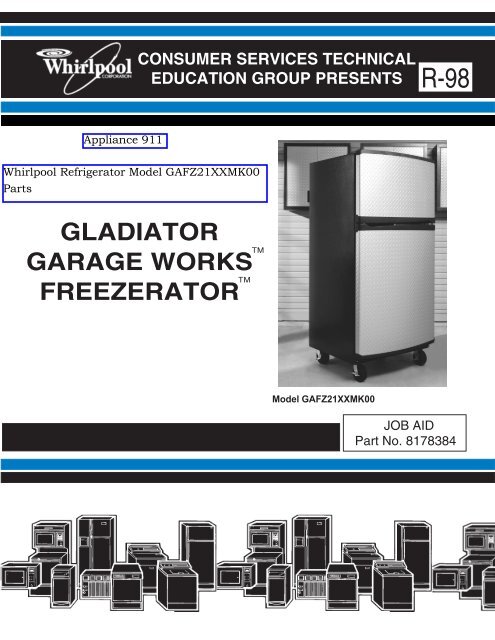
CONSUMER SERVICES TECHNICAL<br />
EDUCATION GROUP PRESENTS R-98<br />
GLADIATOR<br />
GARAGE WORKS<br />
<br />
FREEZERATOR<br />
<br />
Model <strong>GAF</strong><strong>Z21XXMK00</strong><br />
JOB AID<br />
Part No. 8178384
FORWARD<br />
This Whirlpool Job Aid, “<strong>Gladiator</strong> Garage Works <strong>Freezerator</strong> ” (Part No. 8178384), provides the<br />
technician with information on the operation and service of the <strong>Gladiator</strong> Garage Works <strong>Freezerator</strong> . It is to be used as a training Job Aid and <strong>Service</strong> <strong>Manual</strong>. For specific information<br />
on the model being serviced, refer to the “Use and Care Guide,” or “Tech Sheet” provided with the<br />
refrigerator.<br />
The Wiring Diagrams and Strip Circuits used in this Job Aid are typical and should be used for<br />
training purposes only. Always use the Wiring Diagram supplied with the product when servicing<br />
the unit.<br />
GOALS AND OBJECTIVES<br />
The goal of this Job Aid is to provide detailed information that will enable the service technician to<br />
properly diagnose malfunctions and repair the <strong>Gladiator</strong> Garage Works <strong>Freezerator</strong> .<br />
The objectives of this Job Aid are to:<br />
• Understand and follow proper safety precautions.<br />
• Successfully troubleshoot and diagnose malfunctions.<br />
• Successfully perform necessary repairs.<br />
• Successfully return the refrigerator to its proper operational status.<br />
WHIRLPOOL CORPORATION assumes no responsibility for any repairs made<br />
on our products by anyone other than Authorized <strong>Service</strong> Technicians.<br />
Copyright © 2003, Whirlpool Corporation, Benton Harbor, MI 49022<br />
- ii -
TABLE OF CONTENTS<br />
Page<br />
GENERAL............................................................................................................................... 1-1<br />
Safety First......................................................................................................................... 1-1<br />
Model & Serial Number Designations ................................................................................ 1-3<br />
Model & Serial Number Label Location ............................................................................. 1-4<br />
Specifications..................................................................................................................... 1-5<br />
THEORY OF OPERATION ..................................................................................................... 2-1<br />
Overview ............................................................................................................................ 2-1<br />
COMPONENT ACCESS ......................................................................................................... 3-1<br />
Component Locations ........................................................................................................ 3-1<br />
Removing The Top Compartment Thermostat<br />
And The Freezer/Refrigerator Selector Switch .............................................................. 3-2<br />
Removing The Auxiliary Heater ......................................................................................... 3-5<br />
Removing The Top Compartment Light Socket And Door Switch ..................................... 3-6<br />
Removing The Evaporator Fan Motor, Liner Heater Bimetal & Defrost Bimetal,<br />
Defrost Heater, And Evaporator .................................................................................... 3-8<br />
Removing The Bottom Compartment Thermostat, Defrost Control,<br />
Light Socket, And Door Switch .................................................................................... 3-11<br />
Removing The Condenser Fan Motor And Ambient Bimetal ........................................... 3-13<br />
Removing The Relay/Overload And Run Capacitor Assembly<br />
And The Compressor................................................................................................... 3-15<br />
Removing A Caster.......................................................................................................... 3-17<br />
Removing A Roller And Condenser Fan Motor Housing ................................................. 3-18<br />
COMPONENT TESTING ........................................................................................................ 4-1<br />
Top Compartment Thermostat & Freezer/Refrigerator Selector Switch ............................ 4-1<br />
Defrost Bimetal & Defrost Heater ...................................................................................... 4-2<br />
Auxiliary Heater ................................................................................................................. 4-3<br />
Liner Heater ....................................................................................................................... 4-3<br />
Liner Heater Bimetal .......................................................................................................... 4-4<br />
Ambient Bimetal................................................................................................................. 4-4<br />
Bottom Compartment Thermostat ..................................................................................... 4-5<br />
Door Switch ....................................................................................................................... 4-5<br />
Relay/Overload & Run Capacitor....................................................................................... 4-6<br />
Compressor ....................................................................................................................... 4-6<br />
- iii -
DIAGNOSTICS & TROUBLESHOOTING .............................................................................. 5-1<br />
Diagnostics ........................................................................................................................ 5-1<br />
Adaptive Defrost Control (ADC) Test Mode................................................................... 5-1<br />
Troubleshooting Chart ....................................................................................................... 5-2<br />
WIRING DIAGRAMS & STRIP CIRCUITS ............................................................................. 6-1<br />
Wiring Diagram 1 ............................................................................................................... 6-1<br />
Wiring Diagram 2 ............................................................................................................... 6-2<br />
Strip Circuits ...................................................................................................................... 6-3<br />
- iv -<br />
Page
Electrical Shock Hazard<br />
Disconnect power before servicing.<br />
Replace all parts and panels before<br />
operating.<br />
Failure to do so can result in death or<br />
electrical shock.<br />
GENERAL<br />
SAFETY FIRST<br />
Your safety and the safety of others is very important.<br />
We have provided many important safety messages in this Job Aid and on the appliance. Always<br />
read and obey all safety messages.<br />
This is the safety alert symbol.<br />
This symbol alerts you to hazards that can kill or hurt you and others.<br />
All safety messages will follow the safety alert symbol and either the word<br />
“DANGER” or “WARNING.” These words mean:<br />
You can be killed or seriously injured if you don’t<br />
immediately follow instructions.<br />
You can be killed or seriously injured if you don’t<br />
follow instructions.<br />
All safety messages will tell you what the potential hazard is, tell you how to reduce the chance<br />
of injury, and tell you what can happen if the instructions are not followed.<br />
1-1<br />
Electrical Shock Hazard<br />
Plug into a grounded 3-prong outlet.<br />
Do not remove ground prong.<br />
Do not use an adapter.<br />
Do not use an extension cord.<br />
Failure to follow these instructions can<br />
result in death, fire, or electrical shock.
Electrical Shock Hazard<br />
Connect green ground wire to ground<br />
screw.<br />
Failure to do so can result in death or<br />
electrical shock.<br />
1-2<br />
ELECTROSTATIC DISCHARGE<br />
(ESD) SENSITIVE ELECTRONICS<br />
ESD problems are present everywhere. ESD<br />
may damage or weaken the electronic control<br />
assembly. The new control assembly may appear<br />
to work well after repair is finished, but<br />
failure may occur at a later date due to ESD<br />
stress.<br />
• Use an antistatic wrist strap. Connect the<br />
wrist strap to a green ground connection<br />
point or unpainted metal in the appliance; or<br />
touch your finger repeatedly to a green ground<br />
connection point or unpainted metal in the<br />
appliance.<br />
• Before removing the part from its package,<br />
touch the antistatic bag to a green ground<br />
connection point or unpainted metal in the<br />
appliance.<br />
• Avoid touching electronic parts or terminal<br />
contacts. Handle the electronic control assembly<br />
by the edges only.<br />
• When repackaging the failed electronic control<br />
assembly in an antistatic bag, observe<br />
the above instructions.
MODEL & SERIAL NUMBER DESIGNATIONS<br />
MODEL NUMBER SERIAL NUMBER<br />
MODEL NUMBER GA FZ 21 X X M K 00<br />
BRAND<br />
PRODUCT GROUP<br />
AC = Accessory<br />
CP = Compactor<br />
CS = Cleaning Station<br />
DP = Display For Trade Partner<br />
FL = Flooring<br />
FM = Floor Module<br />
FZ = <strong>Freezerator</strong><br />
GB = Gear Box<br />
GD = Gear Drawer<br />
GP = Gator Pak<br />
RF = Refrigerator<br />
RK = Gear Rack<br />
TB = Tall Gear Box<br />
TL = Tall Gear Locker<br />
VA = Vacuum<br />
WA = Wall Accessory<br />
WB = Workbench<br />
WG = Wall Gear Box<br />
CAPACITY/CUBIC FOOT<br />
SIZE (IN / FT / OR CU FT)<br />
05 = 5 cu ft or 5′ 30 = 30″<br />
06 = 6′<br />
XX = No Size<br />
08 = 8′<br />
10 = 10′<br />
15 = 15″<br />
18 = 18″<br />
19 = 19″<br />
21 = 21 cu ft<br />
24 - 24″<br />
27 = 27″<br />
28 = 28″<br />
MODEL TYPE<br />
1D = One Door PD = Pump Drain<br />
2D = Two Doors PS = Power Strip<br />
1P = One Piece SF = Shelf<br />
2P = Two Pieces SH = S Hook<br />
6P = Six Pieces SK = Starter Kit<br />
BD = Builder Display SR = Shoe Rack<br />
BH = Big Hook TH = Tool Hook<br />
BK = Basket TR = Tool Rack<br />
DD = Direct Drain UH = Utility Hook<br />
DH = Deep Hook VB = Vert. Bike Hook<br />
MT = Maple Top WH = Whlbarrow Hook<br />
XX = No Type<br />
YEAR OF INTRODUCTION<br />
M = 2003, P = 2004, R = 2005<br />
COLOR CODE<br />
G = Hammered Granite Y = Gray<br />
H = Hammered Graphite X = No Color<br />
K = Graphite<br />
ENGINEERING CHANGE (NUMERIC)<br />
00 = Original, 01 = 1st Change, 02 = 2nd Change, Etc.<br />
1-3<br />
SERIAL NUMBER<br />
MANUFACTURING SITE<br />
E = Evansville, IN<br />
YEAR OF PRODUCTION<br />
P = 2003<br />
WEEK OF PRODUCTION<br />
03 = 3rd Week<br />
PRODUCT SEQUENCE NUMBER<br />
E P 03 10001
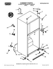
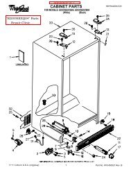
MODEL & SERIAL NUMBER LABEL LOCATION<br />
The Model/Serial Number Label location is shown below.<br />
Model & Serial Number Location<br />
(Upper Left Refrigerator Liner)<br />
1-4
SPECIFICATIONS<br />
MODEL NUMBER <strong>GAF</strong>Z21XXMK<br />
Total AHAM Volume (Cu Ft) 21.0<br />
Top Compartment Volume (Cu Ft) 5.67<br />
Freezer Volume (Cu Ft) 15.37 Bottom Compartment<br />
Total AHAM Shelf Area (Sq Ft)<br />
Exterior Dimensions (Nearest 1/8")<br />
29.9<br />
Cabinet Height (Floor To Top Of Cabinet) (in) 72 3/4"<br />
Overall Height (Floor To Top Of Hinge Covers) (in) 73 3/4"<br />
Cabinet Width (in) 33 1/8"<br />
Overall Depth (Including Hardware & Handles) (in) 31 1/2"<br />
Depth - Less Doors/Base Grille (Minimum Opening) (in) 26 7/8"<br />
Weight (Indicate Net/Shipping/Crated)<br />
Exterior<br />
271 lb/280 lb/280 lb<br />
Factory-Built Door Swing Right-Hand Reversible<br />
Cabinet Color(s) Graphite<br />
Exterior Door<br />
Warranty<br />
1-5<br />
Contoured / Tread Plate<br />
Silver Tread<br />
12 Month Standard 60 Month<br />
Full Liner & Sealed System
— NOTES —<br />
1-6
THEORY OF OPERATION<br />
The <strong>Gladiator</strong> Garage Works <strong>Freezerator</strong> is<br />
a freezer with a top compartment that is convertible<br />
to a refrigerator or freezer. <strong>Freezerator</strong><br />
is designed to operate properly in the temperatures<br />
often found in a typical garage.<br />
<strong>Freezerator</strong>’s sealed system uses a larger<br />
capacity compressor, an increased refrigerant<br />
charge, more fins on the evaporator, and a<br />
faster speed evaporator fan motor. These<br />
changes allow <strong>Freezerator</strong> to operate properly<br />
in higher-than-normal ambient temperatures.<br />
Other sealed system changes include a suction<br />
line accumulator that allows the unit to<br />
operate safely in low ambient temperatures,<br />
and a heat loop that surrounds both compartments.<br />
To allow the top compartment to operate as a<br />
refrigerator, insulation has been added to the<br />
evaporator cover, and two heaters have been<br />
added to the top compartment. A unit compartment<br />
bimetal, located on the compressor process<br />
stub, opens at 88°F (31°C), and closes at<br />
76°F (24°C). These temperatures translate<br />
into the following ambient (room) temperatures:<br />
opens at 60°F (16°C), and closes at 55°F<br />
(13°C).<br />
When this ambient bimetal closes, and the top<br />
compartment is set for refrigeration, the 18 watt<br />
liner heater is energized. A 60 watt heater that<br />
is attached to the back of the evaporator cover<br />
is cycled on and off by the convertible compartment<br />
thermostat during the refrigeration mode,<br />
and maintains the refrigeration temperature in<br />
the convertible compartment.<br />
OVERVIEW<br />
2-1<br />
During the defrost cycle, if the top compartment<br />
is set to “freezer” mode, the 60 watt<br />
evaporator cover heater may be used, in addition<br />
to the defrost heater, to aid in frost removal.<br />
The 60 watt evaporator cover heater will only<br />
operate during defrost if the top compartment<br />
thermostat is closed, and is set to the freezer<br />
mode. The 18 watt top compartment liner heater<br />
will also operate during defrost if the ambient<br />
bimetal is closed.<br />
The bottom compartment thermostat maintains<br />
the proper freezer temperatures for that<br />
section by controlling the compressor run time.<br />
The bottom compartment thermostat also controls<br />
the top compartment whenever it is used<br />
for freezer operation.<br />
The top compartment controls consist of a<br />
thermostat and a rocker switch. The switch<br />
allows the compartment mode change from<br />
freezer to refrigerator, while the thermostat<br />
portion allows temperature control during refrigeration<br />
operation. The rated ambient operating<br />
temperature of <strong>Freezerator</strong> is from 20 to<br />
110°F (–6.6 to 43°C). Operation as low as 0°F<br />
(–17.7°C) is possible if the top compartment is<br />
operated either in the freezer mode, or is set to<br />
the WARM refrigeration position.<br />
<strong>Freezerator</strong> uses an electronic Adaptive Defrost<br />
Control that incorporates “evaporator fan<br />
delay.” When the compressor cycles on, the<br />
evaporator fan is delayed for 40 seconds.<br />
When the compressor cycles off, the fan continues<br />
to run for an additional 4 minutes. After<br />
a defrost cycle, the compressor is delayed for<br />
3 minutes, and the evaporator fan is delayed<br />
for an additional 3 minutes (6 minutes total).
— NOTES —<br />
2-2
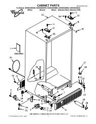
COMPONENT ACCESS<br />
This section instructs you on how to service each component inside the <strong>Freezerator</strong>. The<br />
components and their locations are shown below.<br />
COMPONENT LOCATIONS<br />
Top Compartment<br />
Thermostat & Freezer/Refrigerator<br />
Selector Switch<br />
Auxiliary Heater, Evaporator<br />
Fan Motor, Bimetal, Defrost<br />
Heater, & Evaporator<br />
(Behind Evap Cover)<br />
Liner Heater<br />
(Non-<strong>Service</strong>able)<br />
Bottom Compartment<br />
Thermostat, Defrost<br />
Control, & Light Socket<br />
Bottom Compartment<br />
Door Switch<br />
Caster<br />
Condenser Fan Motor<br />
Ambient Bimetal<br />
Relay/Overload &<br />
Run Capacitor Assembly<br />
3-1<br />
Top Compartment Door<br />
Switch & Light Socket<br />
Compressor<br />
Accumulator
REMOVING THE TOP COMPARTMENT THERMOSTAT AND<br />
THE FREEZER/REFRIGERATOR SELECTOR SWITCH<br />
Electrical Shock Hazard<br />
Disconnect power before servicing.<br />
Replace all parts and panels before<br />
operating.<br />
Failure to do so can result in death or<br />
electrical shock.<br />
1. Unplug refrigerator or disconnect power.<br />
2. Open the top compartment door, remove<br />
the items from the shelf, and remove the<br />
shelf.<br />
3. Remove the two screws from the wiring<br />
cover and remove the cover.<br />
Wiring Cover<br />
W/2 Screws<br />
Control Wire Connectors<br />
Top Compartment<br />
Control Housing<br />
3-2<br />
4. Pull the 6-pin wire connectors for the top<br />
compartment control components out of<br />
the opening and disconnect them (see the<br />
round inset in the lower left column).<br />
5. Remove the six hex-head screws from the<br />
outer evaporator cover.<br />
6. Pull the top of the outer evaporator cover<br />
forward and remove the cover assembly<br />
from the top compartment. Place the assembly<br />
on a work surface with the control<br />
housing facing down.<br />
4 Long Screws<br />
Outer Evaporator Cover<br />
2 Short Screws<br />
7. Disconnect the 2-wire heater connector.<br />
8. Unhook the wires from the clip and push<br />
the rubber grommet out of the cover cutout.<br />
9. Slide the green ground wire clip off the<br />
edge of the cover.<br />
Grommet &<br />
Ground Clip<br />
Wire Clip Heater Connector
10. Remove the screw from the top compartment<br />
control housing.<br />
11. Lift the top compartment control housing<br />
from the outer evaporator cover, pull the<br />
wires through the cutout, and position the<br />
housing with the component side facing<br />
up.<br />
Pull Wires<br />
Through<br />
Cutout<br />
Housing Screw<br />
Top Compartment Control Housing<br />
12. Remove the two hex-head screws from<br />
the top compartment thermostat bracket<br />
and remove the bracket assembly from<br />
the control box.<br />
Thermostat Bracket & 2 Screws<br />
3-3<br />
13. To remove the top compartment thermostat:<br />
a) Pull the knob/baffle off the thermostat<br />
shaft.<br />
b) Disconnect the 3 wire connectors from<br />
the thermostat terminals.<br />
c) Remove the two hex-head screws from<br />
the thermostat and remove the thermostat<br />
from the bracket.<br />
LBu-Blk<br />
Yel-Red<br />
Thermostat<br />
Knob / Baffle<br />
Green<br />
Screw (1 of 2)<br />
14. To remove the freezer/refrigerator selector<br />
switch:<br />
a) Pull the knob/baffle off the thermostat<br />
shaft.<br />
b) Disconnect the 3 wire connectors from<br />
the switch terminals.<br />
Knob / Baffle<br />
Pink<br />
Black<br />
Yel-Red<br />
Freezer/Refrig<br />
Selector Sw.<br />
Continued on the next page.
c) Push in on the locking tab of the switch<br />
and push it out of the bracket cutout.<br />
3-4<br />
Bracket
REMOVING THE AUXILIARY HEATER<br />
Electrical Shock Hazard<br />
Disconnect power before servicing.<br />
Replace all parts and panels before<br />
operating.<br />
Failure to do so can result in death or<br />
electrical shock.<br />
1. Unplug refrigerator or disconnect power.<br />
2. Remove the outer evaporator cover (see<br />
steps 2 through 7 on page 3-2 for the procedure).<br />
3-5<br />
3. Peel the auxiliary heater off the outer<br />
evaporator cover and install the new one<br />
in its place.<br />
Outer Evaporator Cover<br />
Auxiliary Heater
REMOVING THE TOP COMPARTMENT<br />
LIGHT SOCKET AND DOOR SWITCH<br />
Electrical Shock Hazard<br />
Disconnect power before servicing.<br />
Replace all parts and panels before<br />
operating.<br />
Failure to do so can result in death or<br />
electrical shock.<br />
1. Unplug refrigerator or disconnect power.<br />
2. Open the top compartment door and remove<br />
any items from around the light and<br />
door switch housing.<br />
Light & Door<br />
Switch Housing<br />
3. Remove the screw from the light and door<br />
switch housing and lower the housing.<br />
Light & Door Switch<br />
Housing Screw<br />
3-6<br />
4. To remove the top compartment light<br />
socket:<br />
a) Remove the insulation from the housing.<br />
Insulation<br />
Housing<br />
b) Press on the locking tab and push the<br />
socket out of the housing cutout.<br />
Locking<br />
Tab<br />
Light<br />
Socket<br />
c) Remove the light bulb from the socket.<br />
d) Disconnect the wires from the light<br />
socket terminals.<br />
Socket<br />
Wires
5. To remove the door switch:<br />
a) Disconnect the wires from the door<br />
switch terminals.<br />
b) Press down on the locking tab and<br />
push the switch out of the housing<br />
cutout.<br />
3-7<br />
Switch Wires<br />
Housing<br />
Locking Tab<br />
Door Switch
REMOVING THE EVAPORATOR FAN MOTOR,<br />
LINER HEATER BIMETAL & DEFROST BIMETAL,<br />
DEFROST HEATER, AND EVAPORATOR<br />
Electrical Shock Hazard<br />
Disconnect power before servicing.<br />
Replace all parts and panels before<br />
operating.<br />
Failure to do so can result in death or<br />
electrical shock.<br />
1. Unplug refrigerator or disconnect power.<br />
2. Remove the outer evaporator cover (see<br />
steps 2 through 7 on page 3-2 for the procedure).<br />
3. Lift the front of the top compartment floor<br />
and pull it out of the unit.<br />
Top Compartment Floor<br />
4. Lift and pull the drain pan at a 45° angle<br />
and remove it from the unit.<br />
5. Pull the styrofoam evaporator cover separator<br />
out and remove it from the unit.<br />
Evaporator Cover Separator<br />
Drain Pan<br />
3-8<br />
6. Remove the two screws from the air tower.<br />
7. Pull the top of the evaporator cover forward,<br />
and lift the bottom of the tower out of<br />
the air supply opening.<br />
Air Supply<br />
Opening<br />
2 Air Tower Screws<br />
Air Tower<br />
Evaporator Cover<br />
8. To remove the evaporator fan motor:<br />
a) Disconnect the 2-wire defrost heater<br />
connector, the 2-wire top compartment<br />
light connector, and the 9-wire liner<br />
connector.<br />
b) Pull the liner heater bimetal and the<br />
defrost bimetal off the tubing.<br />
c) Remove the wiring from the evaporator<br />
fan motor housing clips.<br />
Defrost Heater<br />
Connector<br />
9-Wire Liner<br />
Connector<br />
Liner Heater Bimetal<br />
Housing Wire Clips<br />
Defrost<br />
Bimetal<br />
Top Compartment<br />
Light Connector<br />
Evaporator Fan Motor
d) Remove the four hex-head rear bracket<br />
screws from the evaporator fan motor<br />
housing and remove the motor.<br />
Fan Motor<br />
Housing<br />
4 Evap Fan Motor Rear Bracket Screws<br />
e) Remove the green ground wire connector<br />
from the motor ground terminal.<br />
f) Disconnect the 2-wire motor connector.<br />
g) Pull the blade off the fan motor shaft.<br />
Green Ground Wire<br />
h) Pull the front bracket off the fan motor.<br />
Front Bracket<br />
Fan Blade<br />
2-Wire Connector<br />
3-9<br />
9. To remove either the liner heater bimetal<br />
or the defrost bimetal:<br />
a) Pull the bimetal off the tubing.<br />
b) Follow the instructions that were supplied<br />
with the replacement bimetal to<br />
connect the wires.<br />
Liner<br />
Heater<br />
Bimetal<br />
Defrost<br />
Bimetal<br />
10. To remove the defrost heater:<br />
a) Disconnect the 2-wire defrost heater<br />
connector from the main harness.<br />
b) Unclip the defrost heater wire from the<br />
top of the evaporator fan motor housing<br />
clips.<br />
c) Pull the two styrofoam blocks from the<br />
left and right sides of the evaporator.<br />
Defrost Heater<br />
Connector<br />
Styrofoam<br />
Blocks<br />
Housing Wire Clips<br />
Defrost Heater<br />
Continued on the next page.
d) Bend the left, center, and right bottom<br />
bracket tabs so that you can remove<br />
the defrost heater.<br />
e) Unclip the bottom left side of the defrost<br />
heater, pull the heater from the three<br />
brackets, and remove the heater from<br />
the unit.<br />
Unclip<br />
Heater<br />
Bend Tab Up<br />
Center & Right<br />
Brackets<br />
Left Bracket<br />
3-10<br />
11. To remove the evaporator:<br />
a) Remove the defrost heater (see step<br />
10 for the procedure).<br />
b) Unclip the bimetals from the evaporator<br />
tubing (see the photo under step<br />
8c).<br />
c) Access the sealed system and discharge<br />
the refrigerant into an approved<br />
recovery system.<br />
d) Protect the liner back wall and ceiling,<br />
and then unbraze the tubing and remove<br />
and replace the evaporator.<br />
Unbraze<br />
Evaporator<br />
Tubing
REMOVING THE BOTTOM COMPARTMENT THERMOSTAT,<br />
DEFROST CONTROL, LIGHT SOCKET, AND DOOR SWITCH<br />
Electrical Shock Hazard<br />
Disconnect power before servicing.<br />
Replace all parts and panels before<br />
operating.<br />
Failure to do so can result in death or<br />
electrical shock.<br />
1. Unplug refrigerator or disconnect power.<br />
2. Open the bottom compartment door and<br />
remove the items from the top shelf so you<br />
can access the control housing.<br />
Control Housing<br />
3. Remove the screw from the bottom compartment<br />
control housing and lower the<br />
housing.<br />
Screw<br />
3-11<br />
4. Disconnect the 2-wire and 9-wire control<br />
housing connectors and remove the control<br />
housing from the unit. Place the housing<br />
on a work surface with the component<br />
side facing up.<br />
9-Wire Connector<br />
2-Wire Connector<br />
Bottom Compartment<br />
Control Housing Assembly<br />
Light Socket<br />
Defrost Control<br />
Bottom<br />
Compartment<br />
Thermostat<br />
Continued on the next page.
5. To remove the bottom compartment<br />
thermostat:<br />
a) Pull the knob off the shaft.<br />
b) Disconnect the three wire connectors<br />
from the thermostat terminals.<br />
c) Lift the thermostat out of the housing<br />
and unclip the sensing bulb.<br />
Orange Wire<br />
2 Red Wires<br />
6. To remove the defrost control:<br />
a) Disconnect the two wire connectors<br />
from the defrost control terminals.<br />
b) Remove the 2 mounting screws from<br />
the defrost control.<br />
2 Screws<br />
Thermostat<br />
Knob<br />
Defrost<br />
Control<br />
Green Wire<br />
Connectors<br />
3-12<br />
7. To remove the light socket:<br />
a) Disconnect the 2 wire connectors from<br />
the light socket terminals.<br />
b) Press on the locking tab and push the<br />
socket out of the housing cutout.<br />
c) Remove the light bulb from the socket.<br />
Light<br />
Socket<br />
Wires<br />
Locking<br />
Tab<br />
8. To remove the door switch:<br />
a) Using a small screwdriver, press up on<br />
the locking tab and pull the switch out of<br />
the liner cutout.<br />
b) Disconnect the two wires from the door<br />
switch terminals.<br />
Locking Tab<br />
Press Up<br />
Door Switch<br />
Black<br />
Yellow<br />
Wires
REMOVING THE CONDENSER FAN MOTOR<br />
AND AMBIENT BIMETAL<br />
Electrical Shock Hazard<br />
Disconnect power before servicing.<br />
Replace all parts and panels before<br />
operating.<br />
Failure to do so can result in death or<br />
electrical shock.<br />
1. Unplug refrigerator or disconnect power.<br />
2. Pull the refrigerator away from the wall.<br />
3. At the rear of the unit, remove the eight<br />
hex-head screws from the unit compartment<br />
cover and remove the cover. NOTE:<br />
When installing the unit compartment<br />
cover, be sure to hook the lip at the bottom<br />
into the machine base.<br />
Condenser Fan Motor<br />
Unit Compartment<br />
Cover Screw (1 of 8)<br />
Ambient Bimetal<br />
3-13<br />
4. To remove the condenser fan motor:<br />
a) Remove the speed nut from the fan<br />
blade and remove the blade.<br />
Fan Blade<br />
Speed Nut<br />
b) Remove the 2 hex-head screws from<br />
the condenser fan motor and remove<br />
the motor from the bracket.<br />
Motor Screw<br />
(1 of 2)<br />
Continued on the next page.
c) Disconnect the wire connector from the<br />
motor.<br />
Motor Connector<br />
3-14<br />
5. To remove the ambient bimetal:<br />
a) Unclip the bimetal from the compressor<br />
process stub. NOTE: When reinstalling<br />
the bimetal on the process stub, keep<br />
the bimetal as close to the compressor<br />
as possible.<br />
b) Follow the instructions supplied with<br />
the replacement bimetal to connect it to<br />
the unit.<br />
Ambient<br />
Bimetal
REMOVING THE RELAY/OVERLOAD AND<br />
RUN CAPACITOR ASSEMBLY AND THE COMPRESSOR<br />
Electrical Shock Hazard<br />
Disconnect power before servicing.<br />
Replace all parts and panels before<br />
operating.<br />
Failure to do so can result in death or<br />
electrical shock.<br />
1. Unplug refrigerator or disconnect power.<br />
2. Pull the refrigerator away from the wall.<br />
3. Remove the unit compartment cover (see<br />
step 3 on page 3-13 for the procedure).<br />
4. To remove the relay/overload and run<br />
capacitor assembly from the compressor:<br />
a) Unclip the wire spring retainer from the<br />
relay/overload and run capacitor assembly<br />
and remove it.<br />
Wire Spring Retainer<br />
3-15<br />
b) Pull the relay/overload and run capacitor<br />
assembly from the compressor pins.<br />
c) Disconnect the 2-pin connector from<br />
the relay/overload and run capacitor<br />
assembly.<br />
2-Pin Wire Connector<br />
d) Pull the run capacitor off the relay/<br />
overload.<br />
Run Capacitor<br />
Relay/Overload<br />
Relay/Overload<br />
& Run Capacitor<br />
Assembly<br />
Continued on the next page.
5. To remove the compressor:<br />
a) Remove the relay/overload and run capacitor<br />
assembly from the compressor<br />
pins (see step 4).<br />
b) Access the sealed system and discharge<br />
the refrigerant into an approved<br />
recovery system.<br />
c) Unbraze the suction and discharge<br />
lines.<br />
d) Cut the filter/drier from the system (do<br />
not use a torch to remove the filter/<br />
drier).<br />
e) Remove the mounting screws from the<br />
compressor shock mounts and remove<br />
the compressor.<br />
3-16<br />
Shock Mount<br />
& Screw (1 of 4)<br />
Compressor<br />
Filter/Drier<br />
Suction Line<br />
Discharge Line
Electrical Shock Hazard<br />
Disconnect power before servicing.<br />
Replace all parts and panels before<br />
operating.<br />
Failure to do so can result in death or<br />
electrical shock.<br />
1. Unplug refrigerator or disconnect power.<br />
2. Remove all of the items from inside the<br />
unit and remove the shelving.<br />
3. Tape the doors closed.<br />
4. Pull the refrigerator away from the wall.<br />
5. Tip the unit on its side so that the caster<br />
you wish to access is facing away from the<br />
floor.<br />
REMOVING A CASTER<br />
3-17<br />
6. Remove the two 1/2″ and two 3/8″ bolts<br />
from the caster bracket and remove the<br />
caster assembly.<br />
1/2″ Bolts<br />
3/8″ Bolts<br />
7. To remove a caster, remove the four bolts<br />
and locknuts.<br />
Caster<br />
Bolt & Locknut (1 of 4)
REMOVING A ROLLER AND<br />
CONDENSER FAN MOTOR HOUSING<br />
Electrical Shock Hazard<br />
Disconnect power before servicing.<br />
Replace all parts and panels before<br />
operating.<br />
Failure to do so can result in death or<br />
electrical shock.<br />
1. Unplug refrigerator or disconnect power.<br />
2. Remove all of the items from inside the<br />
unit and remove the shelving.<br />
3. Pull the refrigerator away from the wall.<br />
4. If you are removing a front roller only,<br />
open the bottom compartment door, and<br />
remove the grille.<br />
Remove Grille<br />
5. Tape the doors closed.<br />
6. Tip the unit on its side so that the roller you<br />
wish to access is facing away from the<br />
floor.<br />
Front Roller Rear Roller<br />
3-18<br />
7. To remove a rear roller:<br />
a) Remove the 1/2″ and two 3/8″ bolts<br />
from the rear of the unit.<br />
1/2″ Bolt<br />
3/8″ Bolts<br />
Rear Of Unit<br />
b) Lower the rear corner of the base until<br />
the round head of the axle pin is below<br />
the bottom edge of the cabinet.<br />
c) Pull the axle pin from the roller and<br />
remove the roller from the base.<br />
Lower The<br />
Base<br />
Rear Wheel Axle Pin
8. To remove a front roller:<br />
a) Remove the 1/2″ and two 3/8″ bolts<br />
from the rear of the unit on each side<br />
(see the photo in step 7a).<br />
b) Remove the 1/2″ bolt from the front of<br />
the unit on each side.<br />
Front Of Unit<br />
c) Slide the base to the rear of the unit<br />
approximately 1″ so that it clears the<br />
front lip of the unit.<br />
Front Lip<br />
Base<br />
1/2″ Bolt<br />
Slide Base<br />
3-19<br />
d) Lower the front of the base until the<br />
round head of the axle pin is below the<br />
bottom edge of the cabinet.<br />
e) Pull the axle pin from the front roller and<br />
remove the roller from the base.<br />
Front Wheel Axle Pin<br />
Lower Base<br />
9. To remove the condenser fan motor<br />
housing:<br />
a) Slide the base to the rear of the unit<br />
approximately 1″ so that it clears the<br />
front lip of the unit (see steps 8a through<br />
8c for the procedure).<br />
b) Disconnect the condenser fan motor<br />
wiring connector and pull the wires<br />
through the housing cutout.<br />
Motor Connector<br />
Housing Cutout<br />
Continued on the next page.
c) Push the condenser fan motor housing<br />
towards the front of the unit until the pin<br />
is out of the base holder, then tilt the top<br />
of the housing, and remove it from the<br />
unit.<br />
3-20<br />
Remove Pin<br />
From Base<br />
Motor Housing<br />
Pull To Side<br />
& Remove
Before testing any of the components, perform<br />
the following checks:<br />
• Control failure can be the result of corrosion<br />
on connectors. Therefore, disconnecting and<br />
reconnecting wires will be necessary throughout<br />
test procedures.<br />
• All tests/checks should be made with a VOM<br />
or DVM having a sensitivity of 20,000 ohmsper-volt<br />
DC, or greater.<br />
COMPONENT TESTING<br />
Electrical Shock Hazard<br />
Disconnect power before servicing.<br />
Replace all parts and panels before operating.<br />
Failure to do so can result in death or electrical shock.<br />
TOP COMPARTMENT THERMOSTAT<br />
& FREEZER/REFRIGERATOR<br />
SELECTOR SWITCH<br />
Thermostat<br />
Terminals<br />
Knob/Baffle<br />
Selector Switch<br />
Terminals<br />
Refer to page 3-2 for the procedure for servicing<br />
the top compartment thermostat & freezer/<br />
refrigerator selector switch.<br />
1. Unplug refrigerator or disconnect power.<br />
2. Set the ohmmeter to the R x 1 scale.<br />
3. Disconnect the wires from the thermostat<br />
terminals.<br />
4. Clip the ohmmeter test leads to the thermostat<br />
terminals and turn the knob/baffle.<br />
The meter should switch between continuity<br />
(0 Ω) and an open circuit (infinite) at<br />
the trip setting.<br />
4-1<br />
• Check all connections before replacing components,<br />
looking for broken or loose wires,<br />
failed terminals, or wires not pressed into<br />
connectors far enough.<br />
• Resistance checks must be made with power<br />
cord unplugged from outlet, and with wiring<br />
harness or connectors disconnected.<br />
5. Disconnect the wires from the freezer/<br />
refrigerator selector switch terminals.<br />
6. Turn the knob/baffle until the button on the<br />
freezer/refrigerator selector switch is out.<br />
7. Touch the ohmmeter test leads to the<br />
COM and N.C. selector switch terminals.<br />
The meter should indicate continuity (0 Ω).<br />
8. Turn the knob/baffle until the button on the<br />
freezer/refrigerator selector switch is in.<br />
The meter should indicate an open circuit<br />
(infinite).<br />
9. Touch the ohmmeter test leads to the<br />
COM and N.O. selector switch terminals.<br />
With the button pressed in, the meter<br />
should indicate continuity (0 Ω).<br />
10. Turn the knob/baffle until the button on the<br />
freezer/refrigerator selector switch is out.<br />
The meter should indicate an open circuit<br />
(infinite).
DEFROST BIMETAL &<br />
DEFROST HEATER<br />
Electrical Shock Hazard<br />
Disconnect power before servicing.<br />
Replace all parts and panels before operating.<br />
Failure to do so can result in death or electrical shock.<br />
Refer to page 3-8 for the procedure for servicing<br />
the defrost bimetal and defrost heater.<br />
1. Place the unit into the “Adaptive Defrost<br />
Control Test Mode,” and check for the<br />
proper operation of the heater.<br />
NOTE: If the bimetal is closed, the voltage at<br />
the defrost heater terminals will be 120 volts<br />
AC. The remaining steps will allow you to<br />
check the resistance of the defrost heater and<br />
bimetal.<br />
2. Unplug refrigerator or disconnect power.<br />
3. Lower the bottom compartment control<br />
housing to access the bimetal and heater<br />
test points (see page 3-11).<br />
Test Plug<br />
4. Set the ohmmeter to the R x 1 scale.<br />
4-2<br />
5. To test the defrost bimetal:<br />
a) Touch the ohmmeter test leads to the<br />
test plug pins with the pink and brown<br />
wires.<br />
Test Plug<br />
Pk & Br Wires<br />
b) With the bimetal below 20°F (–6.6°C),<br />
the meter should indicate continuity<br />
(0 Ω).<br />
c) With the bimetal above 50°F (10°C), the<br />
meter should indicate an open circuit<br />
(infinite).<br />
6. To test the defrost heater:<br />
a) Touch one of the ohmmeter test leads<br />
to the white wire on the 9-pin connector.<br />
White Wire<br />
b) Touch the other ohmmeter test lead to<br />
the test plug pin with the brown wire.<br />
c) The meter should indicate between 31<br />
and 42 Ω.
AUXILIARY HEATER<br />
Electrical Shock Hazard<br />
Disconnect power before servicing.<br />
Replace all parts and panels before operating.<br />
Failure to do so can result in death or electrical shock.<br />
Refer to page 3-5 for the procedure for servicing<br />
the auxiliary heater.<br />
1. Unplug refrigerator or disconnect power.<br />
2. Set the ohmmeter to the R x 10 scale.<br />
3. Touch one of the ohmmeter test leads to<br />
the test plug pin with the light blue wire with<br />
the black stripe.<br />
Test Plug<br />
Blu-Blk Wire<br />
4. Touch the other ohmmeter test lead to the<br />
white wire on the 9-pin connector (see<br />
step 6 on page 4-2).<br />
5. The meter should indicate between 180<br />
and 360 Ω.<br />
4-3<br />
LINER HEATER<br />
Liner Heaters<br />
1. To check the liner heater, unplug refrigerator<br />
or disconnect power.<br />
2. Set the ohmmeter to the R x 10 scale.<br />
3. Touch one of the ohmmeter test leads to<br />
the test plug pin with the orange wire with<br />
the black stripe.<br />
Test Plug<br />
Org-Blk Wire<br />
4. Touch the other ohmmeter test lead to the<br />
white wire on the 9-pin connector (see<br />
step 6 on page 4-2).<br />
5. The meter should indicate between 706<br />
and 923 Ω.
LINER HEATER BIMETAL<br />
Electrical Shock Hazard<br />
Disconnect power before servicing.<br />
Replace all parts and panels before operating.<br />
Failure to do so can result in death or electrical shock.<br />
Refer to page 3-8 for the procedure for servicing<br />
the liner heater bimetal.<br />
1. Unplug refrigerator or disconnect power.<br />
2. Set the ohmmeter to the R x 1 scale.<br />
3. Touch the ohmmeter test leads to the YL/<br />
RD and GY bimetal wires .<br />
4. With the bimetal below 25°F (–4°C), the<br />
meter should indicate continuity (0 Ω).<br />
With the bimetal above 40°F (4°C), the<br />
meter should indicate an open circuit (infinite).<br />
4-4<br />
AMBIENT BIMETAL<br />
Refer to page 3-13 for the procedure for servicing<br />
the ambient bimetal.<br />
1. Unplug refrigerator or disconnect power.<br />
2. Set the ohmmeter to the R x 10 scale.<br />
3. Disconnect the 9-pin cabinet connector in<br />
the top of the unit compartment.<br />
4. Touch the ohmmeter test leads to pins 5<br />
and 6.<br />
Pin 5<br />
Pin 6<br />
5. If the bimetal is below 76°F (24°C), the<br />
meter should indicate continuity (0 Ω).<br />
With the bimetal above 88°F (31°C), the<br />
meter should indicate an open circuit (infinite).
Electrical Shock Hazard<br />
Disconnect power before servicing.<br />
Replace all parts and panels before operating.<br />
Failure to do so can result in death or electrical shock.<br />
BOTTOM COMPARTMENT<br />
THERMOSTAT<br />
Refer to page 3-11 for the procedure for servicing<br />
the bottom compartment thermostat.<br />
1. Unplug refrigerator or disconnect power.<br />
2. Set the ohmmeter to the R x 1 scale.<br />
3. Disconnect the wires from the thermostat<br />
terminals.<br />
4. Clip the ohmmeter test leads to the thermostat<br />
terminals and turn the control shaft.<br />
5. The meter should switch between continuity<br />
(0 Ω) and an open circuit (infinite) at<br />
the trip setting.<br />
4-5<br />
DOOR SWITCH<br />
Refer to pages 3-6 and 3-11 for the procedures<br />
for servicing a door switch.<br />
1. Unplug refrigerator or disconnect power.<br />
2. Disconnect one of the wires going to the<br />
door switch.<br />
3. Set the ohmmeter to the R x 1 scale.<br />
4. Touch the ohmmeter test leads to the<br />
COM and N.C. door switch terminals. The<br />
meter should indicate continuity (0 Ω).<br />
5. Press the door switch actuator button and<br />
the meter should indicate an open circuit<br />
(infinite).
RELAY/OVERLOAD &<br />
RUN CAPACITOR<br />
Relay/Overload<br />
Electrical Shock Hazard<br />
Disconnect power before servicing.<br />
Replace all parts and panels before operating.<br />
Failure to do so can result in death or electrical shock.<br />
Run Capacitor<br />
Refer to page 3-15 for the procedure for servicing<br />
the relay/overload & run capacitor.<br />
1. Unplug refrigerator or disconnect power.<br />
2. Set the ohmmeter to the R x 10K scale.<br />
3. Remove the relay/overload and run capacitor<br />
assembly from the compressor<br />
pins.<br />
4. Pull the run capacitor off the relay/overload.<br />
5. To test the run capacitor, touch the<br />
ohmmeter test leads to the run capacitor<br />
terminals. The meter should indicate several<br />
ohms and gradually return to infinity.<br />
6. To test the overload, touch the ohmmeter<br />
test leads to the center (C) terminal,<br />
and the terminal where the red wire is<br />
connected to the relay. The meter should<br />
indicate continuity (0 Ω).<br />
7. To test the relay, touch the ohmmeter<br />
test leads to the (M) and (S) terminals. The<br />
meter should indicate continuity (0 Ω).<br />
4-6<br />
COMPRESSOR<br />
Start (S)<br />
Common (C)<br />
Run (M)<br />
Refer to page 3-15 for the procedure for servicing<br />
the compressor.<br />
1. Unplug refrigerator or disconnect power.<br />
2. Set the ohmmeter to the R x 1 scale.<br />
3. Remove the relay/overload and run capacitor<br />
assembly from the compressor<br />
pins.<br />
4. Touch one of the ohmmeter test leads to<br />
the Common (C) pin, and the other lead to<br />
the Start (S) pin. The meter should indicate<br />
between 3 and 11 Ω.<br />
5. Touch one of the ohmmeter test leads to<br />
the Common (C) pin, and the other lead to<br />
the Run (M) pin. The meter should indicate<br />
between 1 and 6 Ω.
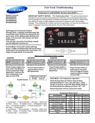
DIAGNOSTICS & TROUBLESHOOTING<br />
DIAGNOSTICS<br />
ADAPTIVE DEFROST CONTROL<br />
(ADC) TEST MODE<br />
The refrigerator/freezer defrost system can be<br />
checked by manually initiating a defrost cycle.<br />
The following shows two methods for initiating<br />
the Adaptive Defrost Control (ADC) Test Mode.<br />
Test Method #1<br />
1. Turn the thermostat off for 15 seconds.<br />
2. Turn the thermostat on for 5 seconds.<br />
3. Turn the thermostat off for 15 seconds.<br />
4 Turn the thermostat on for 5 seconds.<br />
5. Turn the thermostat off for 15 seconds.<br />
6. Turn the thermostat on for 5 seconds.<br />
7. Turn the thermostat off.<br />
The ADC should turn the defrost heater On<br />
within 3 to 8 seconds (with the bimetal closed).<br />
NOTE: The test mode will terminate when the<br />
bimetal opens.<br />
If the refrigerator/freezer is already in defrost,<br />
the test mode can be terminated by unplugging<br />
the refrigerator/freezer from the wall outlet,<br />
waiting 30 seconds, and plugging it back<br />
in. The refrigerator/ freezer should immediately<br />
go into the “cooling” mode if the thermostat is<br />
closed.<br />
If this first test procedure fails to make the ADC<br />
initiate a defrost cycle, use the second test<br />
method to make the ADC begin the test mode.<br />
5-1<br />
Test Method #2<br />
1. Disconnect the refrigerator/freezer from the<br />
wall outlet for at least 30 seconds.<br />
2. Turn the bottom compartment thermostat<br />
Off.<br />
3. Reconnect power to the refrigerator/freezer.<br />
The ADC should turn the defrost heater On<br />
within 3 to 8 seconds (with the bimetal closed).<br />
If the unit fails to go into the defrost mode during<br />
this test, the problem may not be with the<br />
ADC. A defective bimetal may be the cause of<br />
the failure. The ADC will only go into a test<br />
mode if the bimetal is closed. If the ADC senses<br />
an open bimetal, it will return to the cooling<br />
mode within 3 to 8 seconds.<br />
HELPFUL HINT: Upon entering the test mode,<br />
the relay mounted on the ADC board should<br />
turn off the compressor, and turn on the defrost<br />
heater. Listen for the relay to click.<br />
• If the relay clicks once when entering the<br />
test mode, check the defrost heater for 31<br />
to 42 Ω.<br />
• If the relay clicks twice, check for an open<br />
bimetal (allow up to 30 seconds between<br />
clicks).
TROUBLESHOOTING CHART<br />
Problem Possible Cause Test Procedure-Action<br />
Convertible compartment<br />
too cold when set to<br />
refrigerate.<br />
Convertible compartment<br />
too warm when set to<br />
refrigerate. Lower<br />
compartment is normal.<br />
Both compartments<br />
too warm.<br />
Open convertible compartment<br />
thermostat.<br />
Defective combination switch.<br />
Open 60 watt auxiliary heater.<br />
Baffle broken or leaking<br />
evaporator panel seal.<br />
Ambient bimetal not closing at<br />
55°F (room temperature).<br />
5-2<br />
See "Component Testing" section for<br />
test procedure.<br />
See "Component Testing" section for<br />
test procedure.<br />
See "Component Testing" section for<br />
test procedure.<br />
Repair/replace broken baffle or seal<br />
evaporator panel.<br />
See "Component Testing" section for<br />
test procedure.<br />
Open liner heater bimetal.<br />
See "Component Testing" section for<br />
test procedure.<br />
Convertible compartment<br />
thermostat set too low. Ambient Change to a higher setting.<br />
temperature below 20°F.<br />
Convertible compartment<br />
thermostat staying closed.<br />
Ambient bimetal closed above<br />
65°F.<br />
Door not closing or damaged<br />
door gasket.<br />
See "Component Testing" section for<br />
test procedure.<br />
See "Component Testing" section for<br />
test procedure.<br />
Adjust door or correct blockage.<br />
Replace damaged door gasket.<br />
Controls set too warm. Reposition controls to colder setting.<br />
Doors not closing or damaged<br />
door gaskets.<br />
Frost blocking the evaporator<br />
due to defective defrost<br />
bimetal, heater or electronic<br />
control.<br />
Defective evaporator fan<br />
motor.<br />
Defective condenser fan motor.<br />
Defective compressor, relay<br />
overload or run capacitor.<br />
Adjust door or correct blockage.<br />
Replace damaged door gasket.<br />
See "Component Testing" section for<br />
test procedure.<br />
See "Component Testing" section for<br />
test procedure.<br />
See "Component Testing" section for<br />
test procedure.<br />
See "Component Testing" section for<br />
test procedure.<br />
Defective light switch.<br />
See "Component Testing" section for<br />
test procedure.<br />
Refrigerant leak or restriction. Repair sealed system.
WIRING DIAGRAMS & STRIP CIRCUITS<br />
WIRING DIAGRAM 1<br />
6-1
WIRING DIAGRAM 2<br />
6-2
STRIP CIRCUITS<br />
DEFROST (TOP COMPARTMENT TO REFRIGERATOR MODE)<br />
L1 N<br />
ADC Bimetal<br />
Defrost Heater<br />
BK PK BR WH<br />
DEFROST (TOP COMPARTMENT TO FREEZER MODE)<br />
L1 N<br />
ADC<br />
BK PK<br />
Freezer<br />
Refrigerator<br />
PK<br />
Bimetal<br />
Top Compartment<br />
Thermostat<br />
YL/RD<br />
LB/BK<br />
Liner Heater Bimetal<br />
Closes @ 25°F<br />
Opens @ 40°F<br />
YL/RD<br />
Defrost Heater<br />
BR WH<br />
GY<br />
Ambient Bimetal<br />
Closes @ 55°F<br />
(Room Temp)<br />
OR/BK<br />
6-3<br />
60W Auxiliary<br />
Heater<br />
18W Low<br />
Ambient Heater<br />
AUXILIARY HEAT (TOP COMPARTMENT TO REFRIGERATOR MODE)<br />
L1<br />
BK<br />
Freezer<br />
Refrigerator<br />
Top Compartment<br />
Thermostat<br />
YL/RD<br />
LB/BK<br />
Liner Heater Bimetal<br />
Closes @ 25°F<br />
Opens @ 40°F<br />
YL/RD<br />
GY<br />
Ambient Bimetal<br />
Closes @ 55°F<br />
(Room Temp)<br />
OR/BK<br />
60W Auxiliary<br />
Heater<br />
18W Low<br />
Ambient Heater<br />
WH<br />
WH<br />
WH<br />
WH<br />
N
— NOTES —<br />
6-4
— NOTES —<br />
6-5
— NOTES —<br />
6-6
PRODUCT SPECIFICATIONS<br />
AND<br />
WARRANTY INFORMATION SOURCES<br />
IN THE UNITED STATES:<br />
FOR PRODUCT SPECIFICATIONS AND WARRANTY INFORMATION CALL:<br />
FOR TECHNICAL ASSISTANCE WHILE AT THE CUSTOMER’S HOME CALL:<br />
THE TECHNICAL ASSISTANCE LINE: 1-800-253-2870<br />
HAVE YOUR STORE NUMBER READY TO IDENTIFY YOU AS AN<br />
AUTHORIZED SERVICER<br />
FOR LITERATURE ORDERS:<br />
PHONE: 1-800-851-4605<br />
FOR TECHNICAL INFORMATION AND SERVICE POINTERS:<br />
IN CANADA:<br />
FOR WHIRLPOOL PRODUCTS: 1-800-253-1301<br />
FOR KITCHENAID PRODUCTS: 1-800-422-1230<br />
FOR ROPER PRODUCTS: 1-800-447-6737<br />
www.servicematters.com<br />
FOR PRODUCT SPECIFICATIONS AND WARRANTY INFORMATION CALL:<br />
1-800-461-5681<br />
FOR TECHNICAL ASSISTANCE WHILE AT THE CUSTOMER’S HOME CALL:<br />
THE TECHNICAL ASSISTANCE LINE: 1-800-488-4791<br />
HAVE YOUR STORE NUMBER READY TO IDENTIFY YOU AS AN<br />
AUTHORIZED SERVICER
CORPORATION