Ilko K. Ilev, Ph.D. - Washington Academy of Sciences
Ilko K. Ilev, Ph.D. - Washington Academy of Sciences
Ilko K. Ilev, Ph.D. - Washington Academy of Sciences

You also want an ePaper? Increase the reach of your titles
YUMPU automatically turns print PDFs into web optimized ePapers that Google loves.
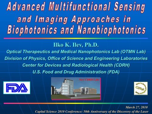
<strong>Ilko</strong> K. <strong>Ilev</strong>, <strong>Ph</strong>.D.<br />
Optical Therapeutics and Medical Nanophotonics Lab (OTMN Lab)<br />
Division <strong>of</strong> <strong>Ph</strong>ysics, Office <strong>of</strong> Science and Engineering Laboratories<br />
Center for Devices and Radiological Health (CDRH)<br />
U.S. Food and Drug Administration (FDA)<br />
New CDRH Labs<br />
March 27, 2010<br />
Capital Science 2010 Conference: 50th Anniversary <strong>of</strong> the Discovery <strong>of</strong> the Laser
PHOTONICS – to – BIOPHOTONICS – to – NANOBIOPHOTONICS<br />
PHOTONICS<br />
PHOTONICS<br />
►laser physics<br />
►electro-optics<br />
►fiber optics<br />
►sensors<br />
►imaging<br />
OPTICAL<br />
THERAPEUTICS<br />
BIOPHOTONICS<br />
BIOPHOTONICS<br />
►optical diagnostics/therapeutics<br />
►biosensing/bioimaging<br />
►tissue engineering<br />
►cell manipulation<br />
MEDICAL<br />
NANOPHOTONICS<br />
(NANOBIOPHOTONICS)<br />
►sizes/distances
Interest in Bioimaging/Microscopy: History <strong>of</strong> Microscopy<br />
Ernst Ruska<br />
Invented the first Electron<br />
Microscope<br />
It is a Transmission Electron<br />
Microscope (TEM)<br />
Imaging <strong>of</strong> objects as small as<br />
the diameter <strong>of</strong> an atom<br />
1668 1932 1981<br />
1931 1957<br />
Antony van Leeuwenhoek<br />
(1632-1723)<br />
The first man who make<br />
and use a real one lens<br />
light microscope<br />
Marvin Minsky<br />
Invented the Confocal<br />
Microscope<br />
Based on the rejection <strong>of</strong><br />
out-<strong>of</strong>-focus information<br />
Three-dimensional and sharp<br />
imaging <strong>of</strong> thick specimens<br />
Frits Zernike<br />
Invented the <strong>Ph</strong>ase-Contrast<br />
Microscope (PCM)<br />
PCM allows the study <strong>of</strong><br />
colorless and transparent<br />
biological materials<br />
He won the Nobel Prize in<br />
<strong>Ph</strong>ysics in 1953<br />
Gerd Binning &<br />
Heinrich Rohrer<br />
Invented the Scanning<br />
Tunneling Microscope (STM)<br />
Three-dimensional imaging<br />
<strong>of</strong> objects down to the atomic<br />
level
MOTIVATION: Why the Interest in Optical Bioimaging/Microscopy?<br />
PUBLIC HEALTH AND REGULATORY IMPACT<br />
optical bioimaging and microscopy remain the most widespread<br />
imaging techniques with important public health impact<br />
optical diagnostics/therapeutic techniques are potential alternatives<br />
to conventional medical methods for diagnosis and therapy<br />
ADVANTAGES OF OPTICAL IMAGING/MICROSCOPY<br />
non-ionizing radiation<br />
non-invasive or minimally invasive imaging, microscopy and<br />
biosensing<br />
high resolution in micron, submicron and nanometric range<br />
MRI - sub-mm; Ultrasound - 150 µm; X-ray - 0.1-1 mm<br />
Electron, Atomic Force and Tunneling Microscopy - nm/sub-nm<br />
limited to specimen surface<br />
not compatible with live cells<br />
require a detrimental sample preparation and vacuum<br />
bulk and expensive equipment<br />
the only imaging method for probing live tissue with subcellular<br />
resolution; potential for imaging and spectroscopic diagnostics
CUTTING EDGE OPTICAL IMAGING DEVICES<br />
Based primarily on confocal microscopy and optical<br />
coherence tomography (OCT)<br />
Cutting edge applications include:<br />
scanning confocal microscope for skin monitoring and diagnostics*<br />
confocal microscope for tissue monitoring and diagnostics*<br />
scanning confocal microscope for corneal diagnostics*<br />
OCT ophthalmology monitoring device*<br />
endoscopic confocal microscope for in vivo imaging *<br />
early cancer detection<br />
intravascular monitoring<br />
human brain function imaging<br />
cellular/intracellular monitoring gene mapping<br />
*FDA Approved
TYPICAL CONFOCAL AND OCT IMAGES<br />
Confocal image <strong>of</strong> neuron growth in mouse brain<br />
[Science, 300 (2003) 76]<br />
Laser scanning confocal image <strong>of</strong> optic disk<br />
OCT image <strong>of</strong> intravascular plaques in human<br />
coronary artery<br />
OCT cellular image in a living African frog<br />
[Science, 298 (2002) 1360]
From Biophotonics to Nanobiophotonics:<br />
From Microscopy To Nanoscopy and Nanobiosensing<br />
in the Subwavelength Nanoscale Spatial Range<br />
MOTIVATION: Why the Interest in Nanobiophotonics?<br />
noninvasive imaging/sensing in subwavelenght (
Diffraction Rayleigh Barrier:<br />
A Fundamental Resolution Limit in Nanobiophotonics<br />
LASER BEAM<br />
LENS<br />
Ultrahigh-Resolution (10000x)<br />
Digital Microscope<br />
Rayleigh Diffraction Resolution Limit<br />
theoretically about one-half<br />
<strong>of</strong> the laser wavelength<br />
d lateral<br />
× λ<br />
=<br />
NA<br />
61 . 0<br />
the highest achievable resolution with objective:<br />
about 180 nm lateral (x-y) resolution<br />
about 500 nm axial (z) resolution<br />
Airy Patterns and the Resolution<br />
Limit
How to Break the Theoretical Diffraction<br />
Barrier in Nanobiophotonics?<br />
RECENTLY DEVELOPED ALTERNATIVE NANOSCOPY<br />
APPROACHES<br />
ULTRAHIGH-RESOLUTION CONFOCAL FIBER-OPTIC<br />
NANOSCOPY AND BIOMEDICAL APPLICATIONS<br />
NOVEL COMBINED BIOPHOTONICS AND<br />
NANOBIOPHOTONICS SENSOR AND IMAGING<br />
APPROACHES
How to Break the Theoretical Diffraction<br />
Barrier in Nanobiophotonics?<br />
RECENTLY DEVELOPED ALTERNATIVE NANOSCOPY<br />
APPROACHES:<br />
Fluorescent Nanoscopy Based on Stimulated Emission<br />
Depletion (STED) Microscopy<br />
[Hell S., Nature Methods 4, 915-918 (2007)]<br />
Near-Field Scanning Optical Microscopy<br />
[Lewis A., Nature Biotechnology 21, pp. 1378-1386 (2003)]<br />
[Betzig E., Science 251, pp. 1468-1470 (1991)]<br />
Widefield Topography<br />
[Lichtman J., Nature Methods 2, pp. 920-931 (2005)]<br />
Dynamic Light Scattering<br />
[EYE, Nature Publishing Group, 16, pp. 429-439 (2002)]
FLUORESCENT NANOSCOPY BASED ON STIMULATED<br />
EMISSION DEPLETION (STED) MICROSCOPY<br />
mitochondrial matrix <strong>of</strong> a live yeast cell<br />
Spatial resolution smaller than 30 nm<br />
Stefan Hell, “Toward Fluorescence Nanoscopy”, Nature Biotechnology 21, 1347 (2003).
How to Break the Theoretical Diffraction<br />
Barrier in Nanobiophotonics?<br />
RECENTLY DEVELOPED ALTERNATIVE NANOSCOPY<br />
APPROACHES<br />
ULTRAHIGH-RESOLUTION CONFOCAL FIBER-OPTIC<br />
NANOSCOPY AND BIOMEDICAL APPLICATIONS<br />
NOVEL COMBINED BIOPHOTONICS AND<br />
NANOBIOPHOTONICS SENSOR AND IMAGING<br />
APPROACHES
ADVANCED BIOPHOTONICS IMAGING TECHNIQUES<br />
CONFOCAL MICROSCOPY<br />
FLUORESENCE REFLECTANCE MULTIPHOTON<br />
PINHOLE-BASED FIBER-OPTIC-BASED<br />
ADVANTAGES:<br />
three-dimensional<br />
sharp<br />
sub-µm resolution<br />
SINGLE-MODE<br />
FIBER<br />
imaging and sensing<br />
<strong>of</strong> thick specimens<br />
MULTI-MODE<br />
FIBER<br />
FIBER BUNDLE<br />
by rejection <strong>of</strong><br />
out-<strong>of</strong>-focus<br />
information<br />
OCT<br />
OPTICAL COHERENCE<br />
TOMOGRAPHY<br />
NFM<br />
NEAR FIELD<br />
MICROSCOPY<br />
DM<br />
DIFFUSED<br />
MICROSCOPY<br />
ODT<br />
OPTICAL DOPPLER<br />
TOMOGRAPHY<br />
OIM<br />
OPTICAL INTERFERENCE<br />
MICROSCOPY
Single-Mode Optical Fiber<br />
Why the Interest in Fiber-Optic Biomedical Technologies<br />
(2 - 9 µm core-diameter)<br />
Advanced Optical Fiber Features<br />
non-invasive or minimally invasive precise delivery <strong>of</strong><br />
non-ionizing laser irradiation<br />
non-invasive or minimally invasive imaging and sensing with<br />
ultrahigh-resolution in micron, sub-micron and nanorange<br />
low attenuation losses at long interaction length (km)<br />
SMF: 3-µm Single hair: 100-µm<br />
small core diameter - micron, sub-micron and nanometer size<br />
flexibility, compactness, scanning potential<br />
Gaussian Laser Beam Intensity Distribution<br />
free <strong>of</strong> gases, dyes, solvents, immunity to external interference<br />
electro-magnetic passive operation (MRI, X-ray compatible)<br />
near-to-the-theoretical paraxial conditions<br />
optimum collimated/focused laser beam<br />
Fiber Tapered Nanoprobes<br />
(20 nm - 1 µm tip-diameter)<br />
biosensing and nanobiosesing: high sensitivity, large dynamic<br />
range and multiparameter sesnsor measurements<br />
point light source<br />
point light receiver<br />
multimodality endoscopic system: imaging, sensing, diagnostics,<br />
and therapeutics<br />
advantages in imaging/sensing designs
Single-Mode Optical Fiber<br />
Why the Interest in Fiber-Optic Biomedical Technologies<br />
(2 - 9 µm core-diameter)<br />
Advanced Optical Fiber Features<br />
non-invasive or minimally invasive precise delivery <strong>of</strong><br />
non-ionizing laser irradiation<br />
non-invasive or minimally invasive imaging and sensing with<br />
ultrahigh-resolution in micron, sub-micron and nanorange<br />
low attenuation losses at long interaction length (km)<br />
SMF: 3-µm Single hair: 100-µm<br />
small core diameter - micron, sub-micron and nanometer size<br />
flexibility, compactness, scanning potential<br />
Gaussian Laser Beam Intensity Distribution<br />
free <strong>of</strong> gases, dyes, solvents, immunity to external interference<br />
near-to-the-theoretical paraxial conditions<br />
Fiber Tapered Nanoprobes<br />
(20 nm - 1 µm tip-diameter)<br />
electro-magnetic passive operation (MRI, X-ray compatible)<br />
optimum collimated/focused laser beam<br />
biosensing and nanobiosesing: high sensitivity, large dynamic<br />
range and multiparameter sesnsor measurements<br />
point light source<br />
point light receiver<br />
multimodality endoscopic system: imaging, sensing, diagnostics,<br />
and therapeutics<br />
advantages in imaging/sensing designs
FIBER-OPTIC-BASED vs CONVENTIONAL PINHOLE-BASED<br />
CONFOCAL MICROSCOPY<br />
CONVENTIONAL PINHOLE-BASED CONFOCAL MICROSCOPE<br />
L<br />
DISADVANTAGES:<br />
HIGH SIGNAL ATTENUATION<br />
DIFFRACTION AND ABERRATION EFFECTS<br />
MISALIGNMENT PROBLEMS<br />
INFLEXIBLE<br />
Ain<br />
BS<br />
D<br />
Aout<br />
O<br />
OBJECT
OUR SUGGESTION<br />
A SIMPLE SUBMICRON CONFOCAL FIBER-OPTIC-BASED<br />
MICROSCOPE<br />
<strong>Ilev</strong>, EYE, 21, 2007, pp. 818-823, Nature Publishing Group<br />
Kim, Kang, <strong>Ilev</strong>, Optics Letters, 33, pp. 425-427, 2008<br />
<strong>Ilev</strong>, Waynant, Gannot, Gandjbakhche, RSI, 78, 2007<br />
<strong>Ilev</strong>, Pending Patent, March 2006<br />
<strong>Ilev</strong>, Waynant, Gannot, Gandjbakhche, Pending Patent, Apr 2006<br />
<strong>Ilev</strong>, Waynant, Byrnes, Anders, Opt. Lett., 27, 1693, 2002<br />
Operating Confocal<br />
Principle<br />
an aperturless reflection<br />
confocal design<br />
no diffraction effects<br />
a regime <strong>of</strong> high output<br />
power is achieved<br />
high sensitivity to spatial<br />
displacements<br />
submicron/nanometric<br />
spatial resolution
How to get over the theoretical diffraction<br />
limit in the Confocal Microscopy?<br />
Signal Power [ µ W]<br />
90<br />
80<br />
70<br />
60<br />
50<br />
40<br />
30<br />
20<br />
10<br />
0<br />
approach A:<br />
B<br />
conventional confocal approach<br />
around the maximum <strong>of</strong> the confocal<br />
response curve<br />
diffraction limited confocal imaging<br />
200-500 nm diffraction limited resolution<br />
A<br />
-12 -8 -4 0 4 8 12<br />
Axial Displacement [ µ m]<br />
approach B:<br />
ultrahigh-resolution confocal fiber-optic<br />
nanoimaging<br />
use <strong>of</strong> the sharp diffraction-free slope <strong>of</strong><br />
the confocal response curve<br />
diffraction-free confocal nanoimaging
ULTRAHIGH-RESOLUTION CONFOCAL FIBER-OPTIC IMAGING<br />
BEYOND THE DIFFRACTION LIMIT IN THE NANOMETRIC SCALE<br />
PRINCIPLE EXPERIMENTAL DESIGN<br />
LASER<br />
POWER<br />
METER<br />
ISO<br />
O1<br />
SINGLE-MODE<br />
FIBER COUPLER<br />
D<br />
Single-mode fiber coupler confocal design: high sensitivity, no diffraction/aberration,<br />
flexibility, scanning potential, point light source/receiver, Gaussian distribution<br />
Combining the advantages <strong>of</strong> the fiber-optic confocal design and the differential<br />
confocal pinhole microscope: working in the subwavelength nanometric range<br />
The use <strong>of</strong> tools and detecting techniques with high signal-to-noise potential<br />
<strong>Ilev</strong>, Waynant, Gannot and Gandjbakhche, PCT International Pending Patent, April 14, 2006<br />
<strong>Ilev</strong>, Waynant, Gannot, Gandjbakhche, Review <strong>of</strong> Scientific Instruments 78, 2007<br />
<strong>Ilev</strong>, Waynant, Gannot, Gandjbakhche, Virtual Journal <strong>of</strong> Nanoscale Science & Technology 16, 2007<br />
<strong>Ilev</strong>, Waynant, Gannot, Gandjbakhche, Virtual Journal <strong>of</strong> Biological <strong>Ph</strong>ysics Research 14, 2007<br />
Small, <strong>Ilev</strong>, Chernomordik, Gandjbakhche, Optics Express, v. 14, 3195 (2006)<br />
O2<br />
S<br />
PZT
Signal Power [mW]<br />
1000<br />
900<br />
800<br />
700<br />
600<br />
SPATIAL RESOLUTION OF THE CONFOCAL FIBER-OPTIC<br />
NANOIMAGING SYSTEM<br />
Signal Power [mW]<br />
875<br />
850<br />
825<br />
800<br />
775<br />
750<br />
725<br />
700<br />
ultrahigh-resolution<br />
fiber-optic<br />
confocal approach<br />
conventional<br />
diffraction limited<br />
confocal approach<br />
An experimental axial<br />
confocal response curve<br />
showing the diffraction-free<br />
slope on the left side <strong>of</strong> the<br />
confocal maximum<br />
100 nm 50 nm 10 nm 2 nm<br />
500<br />
675<br />
750<br />
772<br />
1200 1300 1400 1500 1600 1700 1800 1900 1450 1500 1550 1600 1650 1700 1750 1570 1580 1590 1600 1610 1620 1630 1594 1596 1598 1600 1602 1604 1606<br />
Axial Displacement [nm]<br />
Axial Displacement [nm]<br />
Axial Displacement [nm]<br />
Axial Displacement [nm]<br />
Experimental confocal responses obtained using the ultrahigh-resolution fiber-optic confocal microscope for<br />
achieving a subwavelength depth resolution <strong>of</strong> 100 nm (a), 50 nm (b), 10 nm (c), and 2 nm (d), respectively.<br />
800<br />
790<br />
780<br />
770<br />
760<br />
782<br />
780<br />
778<br />
776<br />
774
How to Break the Theoretical Diffraction<br />
Barrier in Nanobiophotonics?<br />
RECENTLY DEVELOPED ALTERNATIVE NANOSCOPY<br />
APPROACHES<br />
ULTRAHIGH-RESOLUTION CONFOCAL FIBER-OPTIC<br />
NANOSCOPY AND BIOMEDICAL APPLICATIONS<br />
NOVEL COMBINED BIOPHOTONICS AND<br />
NANOBIOPHOTONICS SENSOR AND IMAGING<br />
APPROACHES
HIGH-RESOLUTION CONFOCAL FIBER-OPTIC-BASED<br />
BIOSENSING/IMAGING APPLICATIONS<br />
CONFOCAL FIBER-OPTIC TESTING OF REGULATORY IOL SAMPLES<br />
LASER<br />
ISO O in<br />
PM<br />
Single-Mode Fiber Coupler<br />
(2×1, 50/50)<br />
DUAL-CONFOCAL FIBER-OPTIC BIOSENSOR<br />
LASER<br />
DETECTOR<br />
50/50 FIBER<br />
COUPLER<br />
O c<br />
L test<br />
M total<br />
<strong>Ilev</strong>, “Confocal Fiber-Optic Laser Method for Measuring The Focal<br />
Length <strong>of</strong> Focusing Optics”, Pending Patent, March 3, 2006<br />
<strong>Ilev</strong>, EYE 21, pp. 818-823, 2007, Nature Publishing Group<br />
O1<br />
O2<br />
<strong>Ilev</strong>, Waynant, Byrnes, Anders, Opt. Lett., 27, 1693, 2002
Development <strong>of</strong> Independent Test Methods for Preclinical<br />
Evaluation <strong>of</strong> Fundamental Optical Properties <strong>of</strong> IOLs<br />
Examples<br />
Motivation<br />
Three-piece Mon<strong>of</strong>ocal IOL<br />
6 mm<br />
13 mm<br />
An estimated 20.5 million Americans over age 40 have<br />
cataracts in at least one eye<br />
>3 million surgeries/year in US, >3 billion USD/year cost<br />
Critical importance <strong>of</strong> precise preclinical IOL optical<br />
testing for evaluating the safety and effectiveness<br />
Conventional test methods have specific limitations:<br />
high accuracy both +/- IOL testing, spatial alignment and<br />
subjective imaging<br />
λ=546 nm IOL<br />
refractive-index<br />
IOL<br />
central<br />
thickness<br />
P 1<br />
IOL Fundamental Optical Properties<br />
dioptric power: D IOL = 1/f fl<br />
refractive-index <strong>of</strong> the IOL material<br />
IOL central thickness<br />
reflected glare<br />
light scattering characteristics<br />
imaging quality<br />
spectral transmittance<br />
f fl<br />
F 1
CONFOCAL FIBER-OPTIC LASER METHOD (CFOLM) FOR<br />
MEASURING THE FOCAL LENGTH OF FOCUSING OPTICS<br />
LASER<br />
ISO O in<br />
PM<br />
Single-Mode Fiber Coupler<br />
(2×1, 50/50)<br />
O c<br />
IOL test<br />
Input Gaussian<br />
Laser Beam<br />
CONFOCAL MICROSCOPY FIBER-OPTIC SENSORS AUTOCOLLIMATION METHOD<br />
high-magnification imaging<br />
out-<strong>of</strong>-focus signal rejection<br />
non-contact optical sectioning<br />
sub-µm resolution<br />
high sensing resolution<br />
micrometer size core diameter<br />
compact, flexible<br />
scanning potential<br />
f t<br />
M total<br />
<strong>Ilev</strong>, “Confocal Fiber-Optic Laser Method for Measuring The Focal<br />
Length <strong>of</strong> Focusing Optics”, Pending Patent, March 3, 2006<br />
<strong>Ilev</strong>, EYE 21, 818, 2007, Nature Publishing Group<br />
H<strong>of</strong>fer, Calogero, Faaaland, <strong>Ilev</strong>, J Cataract Refract Surg, 35, Nov 2009<br />
double increased accuracy<br />
simple and compact design
Development <strong>of</strong> Independent Method for Precise IOL Power Testing<br />
Confocal Laser Method (CLM) for IOL Dioptric Power Testing<br />
E4<br />
E3<br />
E2<br />
E1<br />
hν<br />
hν<br />
hν<br />
(develop testing protocols, guidance, standard)<br />
Basic Advantages <strong>of</strong> the Laser Confocal Method<br />
Improved positive and negative power range<br />
Previous: typical – from 5 D to 20 D<br />
New Method: from 0 D to > ±30 D<br />
Greater Accuracy<br />
Previous: typical – several tens <strong>of</strong> microns<br />
New Method:
E4<br />
E3<br />
E2<br />
E1<br />
Development <strong>of</strong> Independent Method for Testing/Identifying the<br />
Source <strong>of</strong> Unwanted Glare Resulting from Implanted IOLs<br />
hν<br />
hν<br />
(pro<strong>of</strong>-<strong>of</strong>-concept and stakeholder contacts)<br />
Glare Simulation Images for Testing/Identifying the Source <strong>of</strong><br />
Unwanted Glare<br />
Landry, <strong>Ilev</strong>, Pfefer, Wolffe, Alpar, EYE, 21, pp.1083-1086, 2007, Nature<br />
Publishing Group
E4<br />
E3<br />
E2<br />
E1<br />
Development <strong>of</strong> Independent Test Method for Precise IOL<br />
Refractive-Index and Thickness Measurement<br />
Non-Contact Dual-Confocal Laser Caliper (pro<strong>of</strong>-<strong>of</strong>-concept)<br />
hν<br />
Signal Power [arb. un.]<br />
260<br />
250<br />
240<br />
230<br />
220<br />
210<br />
200<br />
190<br />
180<br />
F1<br />
LASER<br />
DETECTOR<br />
d<br />
F2<br />
170<br />
0 200 400 600 800 1000 1200 1400 1600<br />
t s<br />
Axial Displacement [µm]<br />
Operating Principle<br />
S1 S2<br />
d = 0.780 mm<br />
t s = 1.219 mm<br />
n s = 1.416<br />
50/50 FIBER<br />
COUPLER<br />
O1<br />
O2<br />
Direct measurement <strong>of</strong> the IOL thickness<br />
in absolute units as well as the thickness <strong>of</strong><br />
nontransparent or highly scattered<br />
biological and human tissue<br />
Determination <strong>of</strong> the IOL refractive-index<br />
Direct measurement <strong>of</strong> local changes in<br />
the refractive index <strong>of</strong> cancer and noncancer<br />
tissue
Fiber-Optic Laser Delivery and Tissue Ablation<br />
Mid-IR On-The-Spot Goldfish Brain Ablation for Parkinson Disease Simulation<br />
α t<br />
MID-IR Er:YAG<br />
LASER<br />
/λ=2.94 μm/<br />
Hollow Taper<br />
hollow taper/smart fiber principle<br />
θ 1<br />
θi<br />
n 0=1<br />
n s>1<br />
θ 2<br />
smart<br />
tissue-activated<br />
fiber tip<br />
Mid-IR Delivery<br />
Hollow Fiber<br />
Smart<br />
Fiber Tip<br />
grazing-incidence<br />
uncoated hollow<br />
optical funnel<br />
laser taper/fiber parameters<br />
Pulse Er:YAG, λ=2.94 μm<br />
150 μm pulse duration, 20 mJ energy<br />
Pyrex-glass uncoated taper<br />
2 mm/600 µm input/output diameter<br />
Mid-IR Hollow fiber<br />
600 µm diameter, 600 mm length
All-Hollow-Fiber Laser Delivery<br />
A Novel Approach for High-Peak Power Homogenous Laser<br />
Delivery in Digital Particle Image Velocimetry (DPIV)<br />
PRINCIPAL OPTICAL ARRANGEMENT<br />
Nd:YAG<br />
LASER<br />
/2ω, λ=532 nm/<br />
Hollow Tapered<br />
Funnel<br />
Delivery Hollow<br />
Waveguide<br />
Powell Lens<br />
<strong>Ilev</strong>, Robinson, Waynant, U.S. Pending Patent, October 30, 2006<br />
O<br />
Laser Sheet<br />
IR IR
(a)<br />
NANOBIOSENSOR FIBER-OPTIC PROBES<br />
Fiber tapered nanobiosensor probes with subwavelength scale<br />
tips (< 100 nm), metal coated and uncoated tips<br />
Design and drawing techniques: precise pulling and chemical<br />
etching<br />
Goals: high reproducibility, maximum light transmission, and<br />
minimum leakage <strong>of</strong> light<br />
(c)<br />
(d)
NANO-PROBES FOR LASER-STIMULATED NEURON GROUTH<br />
illuminating nano-probe Illumination <strong>of</strong> axon (λ=810 nm)<br />
Illumination <strong>of</strong> nucleus (λ=810 nm) Illumination <strong>of</strong> nucleus (λ=632.8 nm)
GRIN<br />
lens<br />
Input fiber<br />
Output fiber<br />
Single Cell/Intracellular Nanoprobing<br />
Input-output fiber<br />
Nano-tip<br />
• Fiber tapered nanoprobes with<br />
subwavelength nanoscale tips (< 100 nm)<br />
• Near-field microscopy combining with<br />
confocal microscopy<br />
• Direct chemical analysis and spectroscopy<br />
<strong>of</strong> single cell components using absorption,<br />
fluorescence and Raman spectroscopy<br />
•Optical stimulation <strong>of</strong> single neurons<br />
• Fiber-optic advantages<br />
– Nano-probe attached/fabricated on a single optical fiber<br />
– Confocal/multi-photon microscope using optical fiber(s)<br />
• Endoscopic advantages<br />
– Easier access to single cells<br />
– One device can be used for imaging, sensing and light delivery
NEAR-FIELD SCANNING OPTICAL MICROSCOPY (NSOM)<br />
NSOM Principle<br />
A light source or detector (or<br />
aperture) with dimensions<br />
much smaller than the<br />
wavelength (λ) <strong>of</strong> light is<br />
placed in close proximity (<<br />
λ/50) to a sample, and then<br />
scanning the aperture or the<br />
sample relative to each other<br />
at a distance much smaller<br />
than a wavelength an image<br />
with spatial resolution better<br />
than the diffraction limit is<br />
generated (
NOVEL CONFOCAL/COMBINED BIOIMAGING/SENSING APPROACHES<br />
(Dr. Do-Hyun Kim, Pr<strong>of</strong>. Jin Kang, Dr. Amir Gandjbakhche, Pr<strong>of</strong>. Juanita Anders)<br />
LASER<br />
BS<br />
OL1<br />
Optical Fibre<br />
ALL-HOLLOW-WAVEGUIDE<br />
CONFOCAL MICROSCOPY<br />
POWER<br />
METER<br />
OL2 OL3<br />
Object<br />
z<br />
Hollow-core photonic bandgap<br />
fiber<br />
Any operating UV, VIS and IR<br />
wavelength can be achieved<br />
Single-mode operation<br />
Small effective area (core<br />
diameter ~ 5 µm)<br />
Wavelength independent<br />
confocal microscopy<br />
Mid-IR confocal microscopy<br />
COMBINED CONFOCAL/OCT<br />
INTERFERENCE MICROSCOPY<br />
SLED<br />
Detector<br />
Kim, Kang, <strong>Ilev</strong>, Electronics Letters, 43, pp. 608-609, 2007<br />
50:50 Coupler<br />
y<br />
x<br />
z<br />
Reference Arm<br />
Object<br />
Sample Arm<br />
Fiber Stretchers<br />
L1<br />
Mirror<br />
Rotating<br />
Mirror<br />
Improved axial CM and lateral OCT resolution<br />
Improved SNR, intensity measurement <strong>of</strong> interference CM<br />
Low coherent light source, reduced unwanted interference<br />
Higher fiber stretcher –frequency (15 kHz), higher NA<br />
Kim, <strong>Ilev</strong>, Kang, IEEE JSTQE, 14, pp. 82-87, 2008<br />
hν e<br />
hν e<br />
Ion-1<br />
UPCONVERSION FLUORESCENCE<br />
CONFOCAL MICROSCOPY<br />
hν f<br />
One-photon process<br />
Energy<br />
transfer<br />
hν e<br />
hν e<br />
hν e<br />
Ion-2<br />
hν f<br />
Two-photon process<br />
hν f<br />
Multiple photons: Excited-state<br />
absorption<br />
Multiple ions: Upconversion by<br />
energy transfer<br />
Unlike the two-photon<br />
microscope, high-efficiency<br />
upconversion fluorophore<br />
enabled the confocal imaging<br />
without using pulse laser and<br />
photo-multiplier tube<br />
SMART, TISSUE-ACTICVATED AND<br />
NANOBIOSENSOR FIBER PROBES<br />
SMART FIBER PROBES<br />
θi<br />
n 0=1<br />
n s>1<br />
NANOBIOSENSOR<br />
FIBER PROBES<br />
Kim, Kang, <strong>Ilev</strong>, Opt. Lett, 33, 427, 2008<br />
Backreflectance Power [uW]<br />
100<br />
80<br />
60<br />
40<br />
20<br />
A B<br />
C D<br />
0<br />
0 4 8 12 16 20<br />
Fiber Displacement [um]
Optical Coherence Tomography (OCT): More than Imaging<br />
Optical Simulation <strong>of</strong> Neurons<br />
Stimulation<br />
Laser<br />
SLED Source<br />
Spectrometer<br />
Computer<br />
( )<br />
Coupler<br />
Mechanical<br />
Module<br />
Offset<br />
SMF<br />
MMF<br />
SMF<br />
dOCT<br />
A<br />
d α<br />
Nerve tissue<br />
(b)<br />
MMF
NANOBIOSENSORS: Rear-Earth Nanoparticle Enhanced Up-<br />
/Down-Conversion Nanobiosensing<br />
rear-earth nanoparticles: can be<br />
tuned to emit at specific optical<br />
wavelengths (VIS, NIR, MIR) via<br />
frequency up-conversion or downconversion<br />
effects<br />
Nanoimaging<br />
Nanobiosensing<br />
Optical Therapeutics (PDT)<br />
Kim, Kang, <strong>Ilev</strong>, “Upconversion fiber-optic confocal<br />
microscopy under near-infrared pumping”, Optics<br />
Letters, 33, 2008<br />
10 nm 50 nm 100 nm 150 nm<br />
hν e<br />
Ion-1<br />
Energy<br />
transfer<br />
hν e<br />
Ion-2<br />
hν f
NANOBIOSENSORS: Plasmonic Nanobiosensor Probes<br />
LSPR (localized surface plasmon resonance): Light incident on the nanoparticles<br />
induces the conduction electrons in them to oscillate collectively with a resonant<br />
frequency that depends on the nanoparticles' size, shape and composition. As a result <strong>of</strong><br />
these LSPR modes, the nanoparticles absorb and scatter light so intensely that single<br />
nanoparticles are easily observed and detected<br />
Noble metal nanoparticles exhibit a strong UV–VIS extinction (absorption and Rayleigh<br />
scattering) band, and that the wavelength <strong>of</strong> maximum extinction is red-shifted by an<br />
increase in the dielectric constant and thickness <strong>of</strong> the material surrounding<br />
the nanoparticles.<br />
Biochemical nanosensors<br />
Surface-enhanced spectroscopies<br />
(SERS and SEFS)<br />
Labels <strong>of</strong> immunoassays<br />
<strong>Ph</strong>otonics Institute, Duke University<br />
Pr<strong>of</strong>. T. Vo-Dinh
From Microscopy To Nanoscopy and Nanobiosensing:<br />
The Future<br />
non-invasive 3D nanoimaging in subwavelenght (
ACKNOWLEDGEMENTS:<br />
OTMNLab Members<br />
Dr. Ron Waynant<br />
Dr. Darrell Tata<br />
Dr. Do-Hyun Kim<br />
Dr. S<strong>of</strong>ia Tan<br />
Robert James<br />
Robert Landry<br />
Outside Collaborators<br />
FDA/CDRH Collaborators<br />
Don Calogero, ODE/CDRH<br />
Richard Weiblinger, ODE/CDRH<br />
Dr. Victor Krauthamer, OSEL/CDRH<br />
Dr. Elizabeth Katz, OSEL/CDRH<br />
Ron Robinson, OSEL/CDRH<br />
Dr. Josh Pfefer, OSEL/CDRH<br />
Dr. Amir H. Gandjbakhche, NIH<br />
Pr<strong>of</strong>. Juanita Anders, USUHS<br />
Pr<strong>of</strong>. Jin Kang, JHU<br />
Pr<strong>of</strong>. Yu Chen, UMD<br />
Pr<strong>of</strong>. Lihong Wang, <strong>Washington</strong> University, UWStL<br />
Pr<strong>of</strong>. Tuan-Vo Dihn, Duke University<br />
Pr<strong>of</strong>. Esen Ekpek, Wilmer Eye Institute, JHU