WES 1000 Installation Instructions - Sloan Valve Company
WES 1000 Installation Instructions - Sloan Valve Company
WES 1000 Installation Instructions - Sloan Valve Company

Create successful ePaper yourself
Turn your PDF publications into a flip-book with our unique Google optimized e-Paper software.
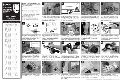
Retrofit<br />
<strong>Installation</strong><br />
<strong>Instructions</strong><br />
<strong>WES</strong>-<strong>1000</strong><br />
Waterfree<br />
Urinal<br />
Insert Tube Cutting Chart<br />
Drain Nipple Depth<br />
Trim<br />
13 7 /8" or greater. ... Do not cut<br />
13 3 /4" or less ...... 1 /4"<br />
13 1 /2" or less ...... 1 /2"<br />
13 1 /4" or less ...... 3 /4"<br />
13" or less ...... 1"<br />
12 3 /4" or less ...... 1 1 /4"<br />
12 1 /2" or less ...... 1 1 /2"<br />
12 1 /4" or less ...... 1 3 /4"<br />
12" or less ...... 2"<br />
11 3 /4" or less ...... 2 1 /4"<br />
11 1 /2" or less ...... 2 1 /2"<br />
11 1 /4" or less ...... 2 3 /4"<br />
11" or less ...... 3"<br />
10 3 /4" or less ...... 3 1 /4"<br />
10 1 /2" or less ...... 3 1 /2"<br />
10 1 /4" or less ...... 3 3 /4"<br />
10" or less ...... 4"<br />
9 3 /4" or less ...... 4 1 /4"<br />
9 1 /2" or less ...... 4 1 /2"<br />
9 1 /4" or less ...... 4 3 /4"<br />
9" or less ...... 5"<br />
8 3 /4" or less ...... 5 1 /4"<br />
8 1 /2" or less ...... 5 1 /2"<br />
8 1 /4" or less ...... 5 3 /4"<br />
8" or less ...... 6"<br />
7 3 /4" or less ...... 6 1 /4"<br />
7 1 /2" or less ...... 6 1 /2"<br />
7 1 /4" or less ...... 6 3 /4"<br />
7" or less ...... 7"<br />
6 3 /4" or less ...... 7 1 /4"<br />
6 1 /2" or less ...... 7 1 /2"<br />
6 1 /4" or less ...... 7 3 /4"<br />
6" or less ...... 8"<br />
5 3 /4" or less ...... 8 1 /4"<br />
5 1 /2" or less ...... 8 1 /2"<br />
5 1 /4" or less ...... 8 3 /4"<br />
5" or less ...... 9"<br />
4 3 /4" or less ...... 9 1 /4"<br />
4 1 /2" or less ...... 9 1 /2"<br />
4 1 /4" or less ...... 9 3 /4"<br />
4" or less ...... 10"<br />
3 3 /4" or less ...... Do not<br />
use tube<br />
Before Starting <strong>Installation</strong>:<br />
Check rough-in height to achieve 24" rim height<br />
(17" rim height for ADA).<br />
Check slope. Downhill slope, per code, is<br />
essential because waterfree urinals depend on<br />
gravity flow.<br />
Check DWV material. Suitable materials include<br />
cast iron, PVC, ABS, and galvanized steel.<br />
Do not install on copper DWV due to copper’s<br />
susceptibility to corrosion.<br />
Shut off water supply and cap the nipple with<br />
the 3 /4" chrome cap (provided).<br />
Customer Service:<br />
Toll Free 888-SLOAN-14 (888-756-2614)<br />
Fax 800-737-3061 • www.sloanvalve.com<br />
1 2 3 4<br />
Lift drain line and<br />
5 6 7<br />
If standing water is present, adjust drain<br />
to achieve pitch (code requires 1/4" drop<br />
per foot of drain line for proper pitch).<br />
Seal wall according to code.<br />
2" side cutter blade<br />
10 11 12 13 Arrow Tab UP 14<br />
15<br />
Cut away wall<br />
brace with a mending plate<br />
Determine the drain nipple depth by<br />
measuring the distance between the<br />
back of the sanitary tee (or elbow) to<br />
the front edge of the brass flange.<br />
Install the gear clamp with the screw<br />
head at the bottom, but do not tighten.<br />
Use utility knife to cut caulk, then use<br />
a putty knife and mallet to remove the<br />
bowl. Remove hanger brackets, scrape<br />
off caulk, and clean the wall.<br />
21 1 /2"<br />
Install plastic<br />
anchor and<br />
screw here<br />
Important: Use a drain machine to<br />
remove build-up inside pipes. Clean<br />
25-35 feet deep then flush with water<br />
to remove cutting debris.<br />
Clean face of existing wall flange then<br />
install the brass flange with the clear<br />
inspection disc. Slowly pour water into<br />
the drain.<br />
8 9<br />
Install<br />
16 3 /4" from finished floor<br />
for standard 24" rim height (9 3 /4" for ADA)<br />
additional<br />
screws here<br />
Incorrect Correct<br />
Measure and mark the rough-in. Use<br />
a 5/16" masonry bit to drill hole, then<br />
install the hanger bracket with one<br />
plastic anchor and screw.<br />
Find the drain nipple depth on the<br />
cutting chart (left) and mark the<br />
specified trim length on the insert tube<br />
at the nearest 1/4" groove.<br />
Level the bracket then mark, drill and<br />
install two additional plastic anchors<br />
and screws. If pre-existing bearing rods<br />
can be used, screws are not necessary.<br />
Cut the tube at the groove using a<br />
sharp utility knife to ensure a square,<br />
flat cut. Clean burrs from the cut end<br />
with emery paper.<br />
Hang the bowl on the bracket and<br />
check tail pipe alignment, then remove<br />
the bowl and adjust the bracket as<br />
needed.<br />
Apply lubricant to the outside of the rubber<br />
bushing and ribbed inside area. Insert<br />
the tube and bushing with the arrow tab<br />
at the top. Lube tailpipe of housing.<br />
16 17 18 19<br />
Drill holes for the lower anchor screws<br />
and insert plastic anchors.<br />
Hang the bowl, inserting tailpipe into<br />
bushing, then install anchor screws<br />
with washers. Tighten flange bolts and<br />
gear clamp.<br />
Pour 5 gallons of water as rapidly as<br />
possible into housing to ensure good<br />
flow and no leaks or standing water.<br />
Use a flashlight to check pitch/slope.<br />
There should be no water present in<br />
the inspection disc or nipple. Remove<br />
flange after inspection.<br />
Tail pipe should<br />
align with center<br />
of drain line<br />
Re-hang and re-check bowl alignment<br />
with the drain line. Mark anchor holes<br />
then remove the bowl without moving<br />
the hanger bracket.<br />
Place the seal into the flange with<br />
the ribs facing out. Install the flange<br />
with washers and hex nuts, but do not<br />
tighten completely.<br />
Caulk bowl to the wall. Install the<br />
cartridge per the cartridge instruction<br />
sheet.<br />
The information in this document is subject to change without notice. © 2009 <strong>Sloan</strong> <strong>Valve</strong> <strong>Company</strong>. All rights reserved. 0816483, Rev 3 (070109)
New Construction<br />
<strong>Installation</strong><br />
<strong>Instructions</strong><br />
<strong>WES</strong>-<strong>1000</strong><br />
Waterfree<br />
Urinal<br />
Before Starting <strong>Installation</strong>:<br />
Check rough-in height to achieve 24" rim height<br />
(17" rim height for ADA).<br />
Check slope. Downhill slope, per code, is<br />
essential because waterfree urinals depend on<br />
gravity flow.<br />
Check DWV material. Suitable materials include<br />
cast iron, PVC, ABS, and galvanized steel.<br />
Do not install on copper DWV due to copper’s<br />
susceptibility to corrosion.<br />
1a<br />
1/2 to 3 /4"<br />
16 3 /4" to<br />
finished floor<br />
(9 3 /4" for ADA<br />
installations)<br />
1b<br />
2 1 /2"<br />
6 13 /16"<br />
Drain<br />
13 5 /8"<br />
21 1 /2"<br />
2 3<br />
Insert Tube Cutting Chart<br />
Drain Nipple Depth<br />
Trim<br />
13 7 /8" or greater. ... Do not cut<br />
13 3 /4" or less ...... 1 /4"<br />
13 1 /2" or less ...... 1 /2"<br />
13 1 /4" or less ...... 3 /4"<br />
13" or less ...... 1"<br />
12 3 /4" or less ...... 1 1 /4"<br />
12 1 /2" or less ...... 1 1 /2"<br />
12 1 /4" or less ...... 1 3 /4"<br />
12" or less ...... 2"<br />
11 3 /4" or less ...... 2 1 /4"<br />
11 1 /2" or less ...... 2 1 /2"<br />
11 1 /4" or less ...... 2 3 /4"<br />
11" or less ...... 3"<br />
10 3 /4" or less ...... 3 1 /4"<br />
10 1 /2" or less ...... 3 1 /2"<br />
10 1 /4" or less ...... 3 3 /4"<br />
10" or less ...... 4"<br />
9 3 /4" or less ...... 4 1 /4"<br />
9 1 /2" or less ...... 4 1 /2"<br />
9 1 /4" or less ...... 4 3 /4"<br />
9" or less ...... 5"<br />
8 3 /4" or less ...... 5 1 /4"<br />
8 1 /2" or less ...... 5 1 /2"<br />
8 1 /4" or less ...... 5 3 /4"<br />
8" or less ...... 6"<br />
7 3 /4" or less ...... 6 1 /4"<br />
7 1 /2" or less ...... 6 1 /2"<br />
7 1 /4" or less ...... 6 3 /4"<br />
7" or less ...... 7"<br />
6 3 /4" or less ...... 7 1 /4"<br />
6 1 /2" or less ...... 7 1 /2"<br />
6 1 /4" or less ...... 7 3 /4"<br />
6" or less ...... 8"<br />
5 3 /4" or less ...... 8 1 /4"<br />
5 1 /2" or less ...... 8 1 /2"<br />
5 1 /4" or less ...... 8 3 /4"<br />
5" or less ...... 9"<br />
4 3 /4" or less ...... 9 1 /4"<br />
4 1 /2" or less ...... 9 1 /2"<br />
4 1 /4" or less ...... 9 3 /4"<br />
4" or less ...... 10"<br />
3 3 /4" or less ...... Do not<br />
use tube<br />
Customer Service:<br />
Toll Free 888-SLOAN-14 (888-756-2614)<br />
Fax 800-737-3061 • www.sloanvalve.com<br />
4 5 6 7<br />
If standing water is present, adjust drain<br />
to achieve pitch (code requires 1 /4" drop<br />
per foot of drain line for proper pitch).<br />
Seal the wall according to code.<br />
9<br />
Determine the drain nipple depth by<br />
measuring the distance between the<br />
back of the sanitary tee (or elbow) to<br />
the front edge of the nipple.<br />
14 15<br />
Drill holes for the lower anchor screws<br />
and insert plastic anchors.<br />
Set drain line height at 16 3 /4" from finished<br />
floor (standard 24" rim) or 9 3 /4"<br />
for ADA installation. Threaded nipple<br />
should extend 1 /2 to 3 /4" from wall.<br />
21 1 /2"<br />
Install plastic<br />
anchor and<br />
screw here<br />
16 3 /4" from finished floor<br />
for standard 24" rim height (9 3 /4" for ADA)<br />
If in-wall carrier is not used, measure and<br />
mark the rough-in. Use a 5 /16" masonry<br />
bit to drill hole, then install the hanger<br />
bracket with one plastic anchor and screw.<br />
Install<br />
additional<br />
screws here<br />
Level the bracket then mark, drill and<br />
install two additional plastic anchors<br />
and screws. If pre-existing bearing rods<br />
can be used, screws are not necessary.<br />
Clean face of existing wall flange then<br />
install the 2" compression nut with<br />
the clear inspection disc. Slowly pour<br />
water into the drain.<br />
Incorrect<br />
Hang the bowl on the bracket and<br />
check tail pipe alignment, then remove<br />
the bowl and adjust the bracket as<br />
needed.<br />
10 11 12 Arrow Tab UP 13<br />
Find the drain nipple depth on the<br />
cutting chart (left) and mark the<br />
specified trim length on the insert tube<br />
at the nearest 1 /4" groove.<br />
Hang the bowl, inserting tailpipe into<br />
bushing, then install anchor screws<br />
with washers.<br />
Carrier stud placement: If using inwall<br />
carrier, set bearing rods as shown<br />
above.<br />
Cut the tube at the groove using a<br />
sharp utility knife to ensure a square,<br />
flat cut. Clean burrs from the cut end<br />
with emery paper.<br />
16<br />
Tighten the compression nut and gear<br />
clamp.<br />
Apply lubricant to the outside of the<br />
rubber bushing and ribbed inside area.<br />
Insert the tube and bushing with the<br />
arrow tab at the top.<br />
17 18<br />
Pour 5 gallons of water as rapidly as<br />
possible into housing to ensure good<br />
flow and no leaks or standing water.<br />
Use a flashlight to check pitch/slope.<br />
There should be no water present in<br />
the inspection disc or nipple. Remove<br />
compression nut after inspection.<br />
8<br />
Correct<br />
Tail pipe should<br />
align with center<br />
of drain line<br />
Re-hang and re-check bowl alignment<br />
with the drain line. Mark anchor holes<br />
then remove the bowl without moving<br />
the hanger bracket.<br />
Place the gear clamp and compression<br />
nut onto the housing tailpipe. Apply<br />
lubricant to the tailpipe.<br />
Caulk bowl to the wall. Install the<br />
cartridge per the cartridge instruction<br />
sheet.<br />
The information in this document is subject to change without notice. © 2009 <strong>Sloan</strong> <strong>Valve</strong> <strong>Company</strong>. All rights reserved. 0816483, Rev 3 (070109)