SERVICE MANUAL
SERVICE MANUAL
SERVICE MANUAL

You also want an ePaper? Increase the reach of your titles
YUMPU automatically turns print PDFs into web optimized ePapers that Google loves.
Website:http://www.LGservice.com [For U.S.A]<br />
www.lg.ca [For Canada]<br />
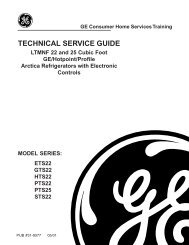
ELECTRIC & GAS DRYER<br />
<strong>SERVICE</strong> <strong>MANUAL</strong><br />
CAUTION<br />
READ THIS <strong>MANUAL</strong> CAREFULLY TO DIAGNOSE<br />
TROUBLES CORRECTLY BEFORE OFFERING <strong>SERVICE</strong>.<br />
MODEL : DLE5977W/DLG5988W<br />
DLE5977B/DLG5988B<br />
DLE3777W/DLG3788W
Feb. 2004 PRINTED IN KOREA<br />
P/No.:3828EL3005A
IMPORTANT SAFETY NOTICE<br />
The information in this service guide is intended for use by individuals possessing adequate backgrounds<br />
of electrical, electronic, and mechanical experience. Any attempt to repair a major appliance may result in<br />
personal injury and property damage. The manufacturer or seller cannot be responsible for the<br />
interpretation of this information, nor can it assume any liability in connection with its use.<br />
! WARNING !<br />
To avoid personal injury, disconnect power before servicing this product. If electrical power is required<br />
for diagnosis or test purposes, disconnect the power immediately after performing the necessary checks.<br />
RECONNECT ALL GROUNDING DEVICES<br />
If grounding wires, screws, straps, clips, nuts, or washers used to complete a path to ground are<br />
removed for service, they must be returned to their original position and properly fastened.<br />
WHAT TO DO IF YOU SMELL GAS:<br />
Do not try to light a match, or cigarette, or turn on<br />
any gas or electrical appliance.<br />
Do not touch any electrical switches. Do not use any<br />
phone in your building.<br />
Clear the room, building or area of all occupants.<br />
IMPORTANT<br />
Immediately call your gas supplier from a neighbor’s<br />
phone. Follow the gas supplier’s instructions<br />
carefully.<br />
If you cannot reach your gas supplier, call the fire<br />
department.<br />
Electrostatic Discharge (ESD)<br />
Sensitive Electronics<br />
ESD problems are present everywhere. ESD may damage or weaken the electronic<br />
control assembly. The new control assembly may appear to work well after repair is<br />
finished, but failure may occur at a later date due to ESD stress.<br />
Use an anti-static wrist strap. Connect wrist strap to green ground connection point or unpainted<br />
metal in the appliance.<br />
- OR -<br />
Touch your finger repeatedly to a green ground connection point or unpainted metal<br />
in the appliance.<br />
Before removing the part from its package, touch the anti-static bag to a green ground connection<br />
point or unpainted metal in the appliance.<br />
Avoid touching electronic parts or terminal contacts; handle electronic control assembly by edges only.<br />
When repackaging failed electronic control assembly in anti-static bag, observe above instructions.<br />
2
CONTENTS<br />
1. SPECIFICATIONS ..................................................................................................................4<br />
2. FEATURES AND BENEFITS .................................................................................................... 5<br />
3. INSTALLATION INSTRUCTIONS ........................................................................................... 6<br />
4. DRYER CYCLE PROCESS..................................................................................................... 12<br />
5. COMPONENT TESTING INFORMATION ..............................................................................13<br />
6. MOTOR DIAGRAM AND SCHEMATIC..................................................................................16<br />
7. CONTROL LAY - OUT .........................................................................................................17<br />
8. WIRING DIAGRAM ............................................................................................................18<br />
9. DIAGNOSTIC TEST .............................................................................................................19<br />
9-1. TEST 1 120VAC ELECTRICAL SUPPLY..........................................................................20<br />
9-2. TEST 2 THERMISTOR TEST --- MEASURE WITH POWER OFF .......................................21<br />
9-3. TEST 3 MOTOR TEST ................................................................................................22<br />
9-4. TEST 4 MOISTURE SENSOR ....................................................................................23<br />
9-5. TEST 5 DOOR SWITCH TEST ...................................................................................24<br />
9-6. TEST 6 HEATER SWITCH TEST - ELECTRIC TYPE...........................................................25<br />
9-7. TEST 7 GAS VALVE TEST - GAS TYPE .........................................................................26<br />
10. CHANGE GAS SETTING (NATURAL GAS, PROPANE GAS) ...............................................27<br />
11. DISASSEMBLY INSTRUCTIONS .........................................................................................29<br />
12. EXPLODED VIEW ..............................................................................................................36<br />
12-1. CONTROL PANEL & PLATE ASSEMBLY .......................................................................36<br />
12-2. CABINET & DOOR ASSEMBLY...................................................................................37<br />
12-3-1. DRUM & MOTOR ASSEMBLY : ELECTRIC TYPE ........................................................38<br />
12-3-2. DRUM & MOTOR ASSEMBLY : GAS TYPE ...............................................................39<br />
13. REPLACEMENT PARTS LIST<br />
3
1<br />
SPECIFICATIONS<br />
Material &<br />
Finishes<br />
ITEM<br />
Color<br />
Top Plate<br />
Door Trim<br />
POWER SUPPLY<br />
ELECTRICITY<br />
CONSUMPTION<br />
MOTOR<br />
HEATER<br />
LAMP<br />
DLE5977W<br />
DLG5988W<br />
Blue White<br />
Porcelain<br />
DLE5977B<br />
DLG5988B<br />
Black<br />
Chromate + STS Deco<br />
120V / 240V 60Hz (26A)<br />
250W (4.5A)<br />
5400W (22.5A)<br />
15W (125mA)<br />
GAS VALVE 13W (110mA) X 2<br />
DLE3777W<br />
DLG3788W<br />
Blue White<br />
Painted<br />
Blue White<br />
REMARK<br />
AC 120V<br />
AC 240V ( ELECTRIC TYPE)<br />
AC 120V<br />
AC 120V ( GAS TYPE)<br />
CONTROL TYPE<br />
Electronic<br />
DRUM CAPACITY<br />
7.3 cu.ft.<br />
Weight (lbs): Net / Gross<br />
126 / 144<br />
No. of Programs<br />
9<br />
7<br />
No. of Dry Option<br />
5<br />
5<br />
No. of Temperature Controls<br />
5<br />
5<br />
No. of Dry Levels<br />
5<br />
5<br />
Audible End of Cycle Beeper<br />
High / Low / Off<br />
Sensor<br />
Moisture<br />
Temperature<br />
Equipped<br />
Equipped<br />
Electro sensor<br />
Thermistor<br />
Reversible Door<br />
Adopted<br />
Drum<br />
Stainless Steel<br />
Dryer Rack<br />
Equipped<br />
Child Lock<br />
Equipped<br />
Interior Light<br />
Equipped<br />
Product (WXHXD)<br />
27" x 42 3 / 4 " x 28 1 / 3 "<br />
Packing (WXHXD)<br />
29 1 / 2 " x 44 3 / 4 " x 30 3 / 4 "<br />
4
2<br />
FEATURES AND BENEFITS<br />
DLE5977W/DLG5988W/DLE5977B/DLG5988B<br />
DLE3777W/DLG3788W<br />
5
3<br />
INSTALLATION INSTRUCTIONS<br />
Review the following options to determine the appropriate electrical connection<br />
for your home:<br />
3-wire receptacle<br />
(NEMA type10-30R)<br />
Use the instructions at this section if your home has<br />
a 3-wire receptacle (NEMA type 10-30R) and you<br />
will be using a UL listed, 120/240 volt minimum,<br />
30 amp, dryer power supply cord.<br />
4-wire receptacle<br />
(NEMA type14-30R)<br />
Use the instructions at this section if your home has<br />
a 4-wire receptacle (NEMA type 14-30R) and you<br />
will be using a UL listed, 120/240 volt minimum,<br />
30 amp, dryer power supply cord.<br />
4-wire connection : Direct wire<br />
Important : The places where a 4-wire connection<br />
is needed are , for example, mobile homes and areas<br />
that local codes do not admit the use of 3-wire<br />
connections.<br />
At least, 5ft(1.52m) of extra length is required in<br />
order for dryer to be able to be moved.<br />
Peel 5 in (12.7cm) of external covering from end<br />
5"<br />
(12.7 cm)<br />
(8.6 of cable, leaving bare ground wire at 5 in (12.7cm).<br />
Cut 1 1 /2 in. (3.8cm) from 3 remaining wires. Peel<br />
insulation back 1in. (2.5cm). Shape ends of wires<br />
like a hook.<br />
1"<br />
(2.5 cm)<br />
3 1 / 2 "<br />
5"<br />
(12.7 cm)<br />
(<br />
5"<br />
(12.7 cm)<br />
3 wire direct<br />
If this type is available at your home. you will be<br />
connecting to a fused disconnect or circuit breaker<br />
box<br />
1"<br />
(2.5 cm)<br />
3 1 / 2 "<br />
(8.6 cm)<br />
1"<br />
(2.5 cm)<br />
Then, put the hooked shape end of the wire under<br />
the screw of the terminal block(hooked end facing<br />
rightward) and pinch the hook together and screw<br />
tightly.<br />
5"<br />
(12.7 cm)<br />
5"<br />
(12.7 cm)<br />
4 wire direct<br />
3 1 / 2 "<br />
(8.6 cm)<br />
If this type is available at your home. you will be<br />
connecting to a fused disconnect or circuit breaker<br />
box<br />
1"<br />
(2.5 cm)<br />
5"<br />
(12.7 cm)<br />
3V2"<br />
(8.9 cm)<br />
1"<br />
(2.5 cm)<br />
3V2"<br />
(8.9 cm)<br />
1.Take off center terminal block screw<br />
2.Take off appliance neutral ground wire(white) from<br />
external ground connector screw. Fasten it under<br />
center, silver colored terminal block screw.<br />
3.Connect ground wire(green) of power supply cable<br />
to external ground conductor screw. Tighten screw.<br />
a<br />
b<br />
d<br />
e<br />
f<br />
c<br />
6<br />
a. External ground connector<br />
b. Green copper wire of power supply cord<br />
c. 3/4 in. (1.9cm) UL-listed strain relief<br />
d. Center silver-colored terminal block screw<br />
e. Neutral grounding wire(white)<br />
f. Neutral wire(white or center wire)
4. Put the hooked shape ends of the wire under the<br />
screw of the terminal block(hooked end facing<br />
rightward) and squeeze the hook together and screw<br />
tightly.<br />
5. Put the hooked shaped ends of the other power<br />
supply cable wires under the outer terminal block<br />
screws(hooked end facing right) and squeeze the<br />
hooked ends together and screw tightly.<br />
1. Take off center terminal block screw<br />
2. Put the hooked end of the neutral wire(white) of<br />
power supply cable under the center screw of<br />
terminal block). Squeeze the hooked end together<br />
3. Connect the hooked ends of the other power<br />
supply cable to the center screw of terminal block.<br />
4. Screw strain relief tightly.<br />
5. Place tab of terminal block cover into slot of<br />
dryer rear panel. Make sure cover with screw.<br />
6. Tighten strain relief screws.<br />
7. Place the tab of terminal block cover into slot of<br />
dryer rear panel. Make sure cover with screw.<br />
)<br />
1"<br />
(2.5 cm)<br />
5"<br />
(12.7 cm)<br />
3-wire connection : Direct wire<br />
Important : The places wherea 4-wire connection is<br />
needed are mobile homes and areas that local codes<br />
do not admit the use of 3-wire connections.<br />
At least, 5ft(1.52m) of extra length is required for<br />
dryer to be able to move.<br />
Peel 5 in (12.7cm) of external covering from end<br />
of cable, 3 leaving bare ground wire at 5 in (12.7cm).<br />
1 / 2 "<br />
Cut 1 1 (8.6 cm)<br />
/2 in. (3.8cm) from 3 remaining wires. Strip<br />
insulation back 1in. (2.5cm). Shape ends of wires<br />
into a hook shape.<br />
1"<br />
(2.5 cm)<br />
3V2"<br />
(8.9 cm)<br />
Then, put the hooked shape end of the wire under<br />
the screw of the terminal block(hooked end facing<br />
rightward) and pinch the hook together and screw<br />
tightly.<br />
a<br />
a. External ground connector<br />
b. Neutral grounding wire (white)<br />
c. Center silver-colored terminal block screw<br />
d. Neutral wire (white or center wire)<br />
e. 3/4 in. (1.9 cm) UL-listed strain relief<br />
c<br />
b<br />
d<br />
e<br />
7
Option 1: 3-Wire Connection with<br />
a Power Supply Cord<br />
lf your local codes or ordinances permit the<br />
connection of a frame-grounding conductor to the<br />
neutral wire, use these instructions. If your local<br />
codes or ordinances do not allow the connection of<br />
a frame-grounding conductor to the neutral wire,<br />
use the instructions under Section 3: Optional<br />
3-wire connection.<br />
a<br />
c<br />
b<br />
d<br />
e<br />
<br />
<br />
a. 3-wire receptacle (NEMA type 10-30R)<br />
b. 3-wire plug<br />
c. Neutral prong<br />
d. Spade terminals with up turned ends<br />
e. 3/4 in. (1.9 cm) UL approved strain relief<br />
f. Ring terminals<br />
g. Neutral (white or center wire)<br />
1. Loosen or remove center terminal block screw.<br />
2. Connect neutral wire (white or center wire) of<br />
power supply cord to the center, silver colored<br />
terminal screw of the terminal block. Tighten<br />
screw.<br />
<br />
<br />
a. External ground connector<br />
b. Neutral grounding wire (white)<br />
c. Center silver-colored terminal block screw<br />
d. Neutral wire (white or center wire)<br />
e. 3/4 in. (1.9 cm) UL-listed strain relief<br />
3. Connect the other wires to outer terminal block<br />
screws. Tighten screws.<br />
4. Tighten strain relief screws.<br />
5. Insert tab of terminal block cover into slot of<br />
dryer rear panel. Secure cover with hold-down<br />
screw.<br />
8
Option 2: 4-wire connection with a<br />
Power supply cord.<br />
• lf your local codes or ordinances do not allow the<br />
use of a 3 wire connection, or you are installing<br />
your dryer in a mobile home, you must use a 4-<br />
wire connection.<br />
a<br />
b<br />
d<br />
e<br />
f<br />
c<br />
a. 4-wire receptable (NEMA type 14-30R)<br />
b. 4-pront plug<br />
c. Ground prong<br />
d. Neutral Prong<br />
e. Spade terminals with upturned ends<br />
f. 3/4 in. (1.9 cm) UL approved strain relief<br />
g. Ring terminals<br />
1. Remove center terminal block screw.<br />
2. Remove appliance neutral ground wire (white)<br />
from external ground connector screw. Fasten it<br />
under the center, silver colored terminal block<br />
screw.<br />
a. External ground connector<br />
b. Green or bare copper wire of power supply cord<br />
c. 3/4 in. (1.9 cm) UL-listed strain relief<br />
d. Center silver-colored terminal block screw<br />
e. Neutral grounding wire (white)<br />
f. Neutral wire (white)<br />
5. Connect the other wires to outer terminal block<br />
screws. Tighten screws.<br />
6. Tighten strain relief screws.<br />
7. Insert tab of terminal block cover into slot of<br />
dryer rear panel. Secure cover with hold-down<br />
screw.<br />
b<br />
c<br />
a<br />
a. External ground connector - Dotted line<br />
shows position of NEUTRAL ground wire<br />
before being moved to center terminal block<br />
screw<br />
b. Center silver-colored terminal block screw<br />
c. White wire of harness<br />
3. Connect ground wire (green or bare) of power<br />
supply cable to external ground conductor screw.<br />
Tighten screw.<br />
4. Connect neutral wire (white or center wire) of<br />
power supply cord to the center, silver colored<br />
terminal screw of the terminal block.<br />
9
Option 3: Optional 3-wire<br />
connection.<br />
• If your local codes or ordinances do not allow the<br />
connection of a frame-grounding conductor to the<br />
neutral wire, use the instructions under this<br />
section.<br />
1. Remove center terminal block screw.<br />
2. Remove appliance neutral ground wire (white)<br />
from external ground connector screw. Connect<br />
appliance ground wire and the neutral wire (white<br />
or center wire) of power supply cord/cable under<br />
center, silver colored terminal block screw.<br />
Tighten screw.<br />
3. Connect the other wires to outer terminal block<br />
screws. Tighten screws.<br />
a<br />
b<br />
c<br />
d<br />
a. External ground connector<br />
b. Neutral grounding wire (white)<br />
c. Neutral wire (white or center wire)<br />
d. Grounding path determined by a qualified electrician<br />
4. Tighten strain relief screws.<br />
5. Insert tab of terminal block cover into slot of<br />
dryer rear panel. Secure cover with hold-down<br />
screw.<br />
6. Connect a separate copper ground wire from the<br />
external ground connector screw to an adequate<br />
ground.<br />
10
3-2. Connect Gas Supply Pipe (Gas Dryer ONLY)<br />
For further assistance, refer to section on Gas Requirements.<br />
1. Make certain your dryer is equipped for use with the<br />
type of gas in your laundry room. Dryer is equipped<br />
at the factory for Natural Gas with a 3/8” N.P.T. gas<br />
connection.<br />
2. Remove the shipping cap from the gas connection<br />
at the rear of the dryer. Make sure you do not<br />
damage the pipe thread when removing the cap.<br />
3. Connect to gas supply pipe using a new flexible<br />
stainless steel connector.<br />
4. Tighten all connections securely. Turn on gas and<br />
check all pipe connections (internal & external) for<br />
gas leaks with a non-corrosive leak detection fluid.<br />
5. For L.P. (Liquefied Petroleum) gas connection, refer<br />
to section on Gas Requirements.<br />
1<br />
2<br />
3<br />
5<br />
4<br />
1 New Stainless Steel Flexible Connector - Use<br />
only if allowed by local codes (Use Design<br />
A.G.A. Certified Connector)<br />
2 1/8” N.P.T. Pipe Plug<br />
(for checking inlet gas pressure)<br />
3 Equipment Shut-Off Valve-Installed within 6’<br />
(1.8 m) of dryer<br />
4 Black Iron Pipe<br />
Shorter than 20’ (6.1 m) - Use 3/8” pipe<br />
Longer than 20’ (6.1 m) - Use 1/2” pipe<br />
5 3/8” N.P.T. Gas Connection<br />
11
4<br />
DRYER CYCLE PROCESS<br />
Default<br />
Conditions of operation and termination<br />
Cycle<br />
Temperature<br />
Dry<br />
Level<br />
Display<br />
time<br />
Drying<br />
Electrosensor<br />
Temp-<br />
Control<br />
Cooling<br />
Default<br />
time<br />
Temp-<br />
Control **<br />
Wrinkle care<br />
Time<br />
HEAVY DUTY<br />
HIGH<br />
(Normal)<br />
54min<br />
Saturation<br />
68±4°C<br />
(5min)<br />
47±5°C<br />
COTTON/<br />
TOWELS<br />
MID<br />
HIGH<br />
(Normal)<br />
55min<br />
Saturation<br />
66±4°C<br />
(5min)<br />
47±5°C<br />
Sensor<br />
Dry *<br />
NORMAL<br />
PERM<br />
PRESS<br />
MEDIUM (Normal)<br />
LOW (Normal)<br />
41min<br />
36min<br />
Saturation<br />
Saturation<br />
60±4°C<br />
52±3°C<br />
(5min)<br />
(5min)<br />
47±5°C<br />
47±5°C<br />
3Hr<br />
DELICATES<br />
LOW<br />
(Normal)<br />
32min<br />
Saturation<br />
52±3°C<br />
(5min)<br />
38±5°C<br />
ULTRA<br />
DELICATE<br />
ULTRA<br />
LOW<br />
(Normal)<br />
34min<br />
Saturation<br />
45±3°C<br />
(5min)<br />
38±5°C<br />
SPEED DRY<br />
(HIGH)<br />
-<br />
25min<br />
Saturation<br />
(70±5°C)<br />
(5min)<br />
(47±5°C)<br />
Manual<br />
Dry **<br />
FRESHEN UP<br />
(MID<br />
HIGH)<br />
-<br />
20min<br />
Saturation<br />
(66±5°C)<br />
(5min)<br />
(47±5°C)<br />
3Hr<br />
AIR DRY -<br />
-<br />
30min<br />
Saturation<br />
No<br />
heater<br />
N/A<br />
N/A<br />
Off Time: 6min<br />
Motor<br />
On Time: 10sec<br />
Load<br />
Temperature Control for each cycle<br />
Heater<br />
* Sensor dry : “Dry Level” is set by users.<br />
** Manual dry : “Temperature control” is set by users.<br />
Default settings can be adjusted by users.<br />
12
5<br />
COMPONENT TESTING INFORMATION<br />
! CAUTION<br />
When checking the Component, be sure to turn the power off, and do voltage discharge sufficiently.<br />
Component Test Procedure Check result Remark<br />
1. Thermal cut off<br />
• Check Top Marking :<br />
N130<br />
2. Hi limit Thermostat<br />
(Auto reset)<br />
Measure resistance of terminal<br />
to terminal<br />
Open at 266 ± 12°F<br />
(130 ± 7°C)<br />
Auto reset -31°F (-35°C)<br />
Same shape as Outlet Thermostat.<br />
Measure resistance of terminal<br />
to terminal<br />
Open at 257 ± 9°F<br />
(125 ± 5°C)<br />
Close at 221 ± 9°F<br />
(105 ± 5°C)<br />
If thermal fuse is open must<br />
be replaced<br />
Resistance value<br />
Continuity (250°F<br />
Resistance value<br />
∞<br />
) < 1Ω<br />
∞<br />
Resistance value < 5Ω<br />
• Heater case-<br />
Safety<br />
• Electric type<br />
• Heater case -<br />
Hi limit<br />
• Electric type<br />
3. Outlet Thermostat<br />
( Auto reset)<br />
• Check Top Marking :<br />
N85<br />
Measure resistance of terminal<br />
to terminal<br />
Open at 185 ± 9°F<br />
(85 ± 5°C)<br />
Close at 149 ± 9°F<br />
(65 ± 5°C)<br />
Same shape as Thermal cut off.<br />
4. Lamp holder Measure resistance of terminal<br />
to terminal<br />
Resistance value<br />
∞<br />
Resistance value < 5Ω<br />
Resistance value :<br />
80Ω ~ 100Ω<br />
• Blow housing -<br />
Safety<br />
• Electric type<br />
5. Door switch Measure resistance of the<br />
following terminal<br />
1) Door switch knob : open<br />
Terminal : “COM” - “NC” (1-3)<br />
Terminal : “COM” - “NO” (1-2)<br />
2) Door switch push : push<br />
Terminal : “COM” - “NC” (1-3)<br />
Terminal : “COM” - “NO” (1-2)<br />
6. Idler switch Measure resistance of the<br />
following terminal :<br />
“COM - NC”<br />
Resistance value < 1Ω<br />
Resistance value ∞<br />
Resistance value ∞<br />
Resistance value < 1Ω<br />
1. lever open<br />
Resistance value < 1Ω<br />
2. Lever push (close)<br />
Resistance value ∞<br />
The state that<br />
Knob is<br />
pressed is<br />
opposite to<br />
Open<br />
condition.<br />
13
Component Test Procedure Check result Remark<br />
7. Heater Measure resistance of the<br />
following terminal<br />
Terminal : 1 (COM) - 2<br />
Terminal : 1 (COM) - 3<br />
Terminal : 2 - 3<br />
Resistance value : 10Ω<br />
Resistance value : 10Ω<br />
Resistance value : 20Ω<br />
• Electric type<br />
8. Thermistor Measure resistance of terminal<br />
to terminal<br />
Temperature condition :<br />
58°F ~ (10~40°C)<br />
58°F ~ 104F (10~40°C)<br />
Resistance value : 10Ω • Heater case -<br />
Hi limit<br />
• Electric type<br />
9. Motor • See Page 13<br />
10. Gas valve<br />
valve 1<br />
Measure resistance of the<br />
following terminal<br />
• Gas type<br />
Valve 1 terminal<br />
Resistance value : > 1.5kg ~<br />
Valve 2 terminal<br />
Resistance value :<br />
> 1.5~2.5kg<br />
valve 2<br />
11. Igniter Measure resistance of terminal<br />
to terminal<br />
Resistance value : 100~800Ω<br />
• Gas type<br />
12. Frame Detect Measure resistance of terminal<br />
to terminal<br />
Open at 370°F ((Maximum)<br />
Close at 320°F<br />
Resistance value<br />
∞<br />
Resistance value < 1Ω<br />
• Gas type<br />
14
Component Test Procedure Check result Remark<br />
13. Outlet Thermostat<br />
(Auto reset)<br />
Measure resistance of terminal<br />
to terminal<br />
Open at 203 ± 7°F (95 ± 5°C)<br />
Close at 158 ± 9°F (70 ± 5°C)<br />
Resistance value<br />
Continuity < 1Ω<br />
∞<br />
• Gas type<br />
• Gas funnel<br />
• Check Top Marking :<br />
N95<br />
13. Outlet Thermostat<br />
(Manual reset)<br />
Measure resistance of terminal<br />
to terminal<br />
Open at 212 ± 12°F<br />
(100 ± 7°C)<br />
Manual reset<br />
If thermal fuse is open must<br />
be replaced<br />
Resistance value ∞<br />
Continuity < 1Ω<br />
• Gas type<br />
• Gas funnel<br />
• Check Top Marking :<br />
N100<br />
15
6<br />
MOTOR DIAGRAM AND SCHEMATIC<br />
NOTE<br />
When checking Component, be sure to turn Power off, then do voltage discharge sufficiently.<br />
Contact On / Off by Centrifugal Switch<br />
STOP MODE<br />
(When Motor does not operate)<br />
RUN MODE<br />
(Motor operates)<br />
Centrifugal switch<br />
Centrifugal switch<br />
(Pull Drive forward)<br />
16
7<br />
CONTROL LAY - OUT<br />
PWB ASSEMBLY DISPLAY LAY-OUT<br />
MODEL DISPLAY AS DIAGNOSTIC TEST<br />
MODEL<br />
OP 1<br />
OP 2<br />
OPTION PART<br />
OP 3 OP 4<br />
OP 5<br />
OP 6<br />
LED<br />
DISPLAY<br />
P/No<br />
DLE5977W/B<br />
X<br />
X<br />
X<br />
O<br />
X<br />
X<br />
18:FO<br />
6871EC1115A<br />
DLG5988W/B<br />
X<br />
X<br />
O<br />
O<br />
X<br />
X<br />
19:FO<br />
6871EC1115B<br />
DLE3777W<br />
X<br />
X<br />
X<br />
X<br />
X<br />
X<br />
18:F1<br />
6871EC1115C<br />
DLG3788W<br />
X<br />
X<br />
O<br />
X<br />
X<br />
X<br />
19:F1<br />
6871EC1115D<br />
PWB ASSEMBLY LAY-OUT<br />
17
8<br />
WIRING DIAGRAM<br />
ELECTRIC DRYER WIRING DIAGRAM<br />
GAS DRYER WIRING DIAGRAM<br />
18
9<br />
DIAGNOSTIC TEST<br />
1. This TEST should be used for Factory test /Service test. Do not use this DIAGNOSTIC TEST other than<br />
specified.<br />
2. Activating the Heater manually with the Door open may trip the Thermostat attached to the Heater, therefore do<br />
not activate it manually. (Do not press the door switch to operate the heater while the door is open )<br />
ACTIVATING THE DIAGNOSTIC TEST MODE<br />
1. Unit must be in Standby (unit plugged in, display off)<br />
2. Press “POWER” while pressing “MORE TIME”, and “LESS TIME” simultaneously.<br />
Pressing the<br />
“START/PAUSE”<br />
button<br />
CHECKING<br />
ACTION<br />
DISPLAY CHECKING POINT REMARK<br />
None<br />
Once<br />
Twice<br />
3 times<br />
During check,<br />
If the door is open.<br />
During check,<br />
If the door is closed.<br />
Electric control<br />
&<br />
Temperature<br />
sensor<br />
Motor<br />
ELECTRIC TYPE<br />
Motor + Heater 1 (2700W)<br />
GAS TYPE<br />
Motor + Valve<br />
ELECTRIC TYPE<br />
Motor + Heater 1<br />
+Heater 2 (5400W)<br />
GAS TYPE<br />
Motor Type<br />
70 ~ 239<br />
Measured<br />
Moisture Value.<br />
Current Temp.<br />
Current Temp.<br />
(5 ~ 70)<br />
Motor on & Heater<br />
Off + Lamp Off 70 ~ 239<br />
19<br />
Won’t power up<br />
Defective LED<br />
Thermistor open<br />
Thermistor close<br />
Motor runs<br />
Displays Moisture Sensor Operation:<br />
If moisture sensor is contacted with<br />
damp cloth. The display number is<br />
below 180, in normal condition.<br />
ELECTRIC TYPE : Heater runs<br />
GAS TYPE : GAS Valve runs<br />
(Display the Temperature of<br />
Inside drum.)<br />
4 times Control Off Auto Off<br />
Motor & Heater Off + Lamp On +<br />
Door switch See test 6<br />
Buzzer beeps seven times<br />
Lamp<br />
• Press Start button 1 time and then open the<br />
door. Proceed again with the step 1(by pressing<br />
start 1 time), step 2(by pressing start 2 times),<br />
step 3(by pressing start 3 times) and step 4(by<br />
pressing start 4 times) in sequence.<br />
• Press Start 2 times and then open the door. Proceed<br />
again from the step 1 all the way to the step 4.<br />
• Press Start 3 times and then open the door<br />
Proceed with the step 1 and skip the step 2 and<br />
press step 3 twice and finish with step 4 by<br />
making sure the all the electric devices shut off<br />
in the end.<br />
See test 1<br />
Display : See page<br />
See test 2<br />
See test 3<br />
See test 4<br />
Gas valve<br />
See test 7
Test 1 120VAC Electrical supply<br />
Caution<br />
When measuring power, be sure to wear insulated gloves, to and avoid an<br />
electric shock.<br />
Trouble Symptom<br />
No power was applied to Controller. (LED, Display off)<br />
Measurement Condition<br />
With Dryer Power On; Connector linked to Controller.<br />
Check the outlet, is the voltage<br />
110V ~ 125V AC?<br />
NO<br />
• Check the fuse<br />
or circuit breaker.<br />
YES<br />
Check if the voltage measured between<br />
Connector “RD3- ” (Black) linked to the<br />
Controller and “WH3- ”(White) is<br />
110V ~ 125V?<br />
NO<br />
• Check if Power<br />
Cord is properly<br />
connected.<br />
YES<br />
L (Black)<br />
N(White)<br />
L (Led)<br />
Check if the Controller wire is<br />
disconnected.<br />
Check if Terminal Block and Power Cord<br />
are connected (Check Plug ).<br />
- Does Power Cord N( Natural) line match<br />
to Terminal Center N(Natural) line?<br />
NO<br />
• Reconnect the<br />
controller.<br />
YES<br />
Replace controIler.<br />
20
Test 2 Thermistor Test --- Measure with Power Off<br />
Caution<br />
Trouble Symptom<br />
Measurement Condition<br />
Before measuring resistance, be sure to turn Power off, and do voltage discharge.<br />
(When discharging, contact the metal plug of Power cord with the Ground.)<br />
During Diagnostic Test, tE1 and tE2 Error occur.<br />
During operation, Heater would not turn off, or remains on.<br />
Difference between actual and sensed temperature is significant.<br />
After turning Power off, measure the resistance.<br />
Take 6pin Connector from<br />
the Controller.<br />
Check if resistance is in the range of Table 1<br />
when measuring 6pin connector Pin<br />
(Blue wire) and Pin (Red wire) connected<br />
to Controller.<br />
YES<br />
• Check if Control<br />
and 6Pin<br />
connector is<br />
properly<br />
connected.<br />
• Replace<br />
Controller.<br />
NO<br />
Check if resistance is in the range of Table 1<br />
when measuring resistance between<br />
terminals after separating Harness<br />
From Thermistor assembly Connector.<br />
NO<br />
• Replace<br />
Thermistor.<br />
YES<br />
Check Harness-linking connector.<br />
Table 1. Resistance for Thermistor Temperature.<br />
Air TEMP.[°F (°C)]<br />
RES. [kΩ] Air TEMP.[°F (°C)] RES. [kΩ] Air TEMP.[°F (°C)] RES. [kΩ]<br />
50°F (10°C)<br />
18.0<br />
90°F (32°C)<br />
7.7<br />
130°F (54°C)<br />
2.9<br />
60°F (16°C)<br />
14.2<br />
100°F (38°C)<br />
6.2<br />
140°F (60°C)<br />
3.0<br />
70°F (21°C)<br />
11.7<br />
110°F (43°C)<br />
5.2<br />
150°F (66°C)<br />
2.5<br />
80°F (27°C)<br />
9.3<br />
120°F (49°C)<br />
4.3<br />
160°F (71°C)<br />
2.2<br />
21
Test 3 Motor test<br />
Caution<br />
Before measuring resistance, be sure to turn Power off, and do voltage discharge.<br />
(When discharging, contact the metal plug of Power cord with earth line.)<br />
Trouble Symptom<br />
Drum will not rotate; No fan will function; No Heater will work.<br />
Measurement Condition<br />
Turn the Dryer’s Power Off, then measure resistance.<br />
Is resistance below 3Ω between Connector<br />
“WH3- ” (White wire) and “BL2- ” (Brown wire)?<br />
Measure while door is closed.<br />
NO<br />
Is resistance below 3Ω between Connector<br />
“WH3- ” (White wire) and “BL2- ” (Yellow wire)?<br />
Measure while door is closed.<br />
YES<br />
YES<br />
NO<br />
• Replace Control.<br />
(Relay check)<br />
• Check Controller<br />
connector.<br />
• Check if Door flame<br />
presses door switch<br />
knob.<br />
• Check Door Switch.<br />
• Check Harness<br />
connection.<br />
Is resistance below 3Ω between Connector<br />
“BL2- ” (Yellow wire) and “BL2- ” (Brown wire)?<br />
NO<br />
YES<br />
• Replace Control.<br />
(Relay check)<br />
• Check Controller<br />
connector.<br />
Is resistance below 1Ω between terminals<br />
of Outlet Thermostat attached to blower housing?<br />
YES<br />
Does Idle Switch attached to Motor Bracket<br />
operate Level by drum belt?<br />
(Not operating Lever is normal.)<br />
NO<br />
YES<br />
• Replace Outlet<br />
• Thermostat.<br />
(Refer to<br />
‘Component’)<br />
• Check Idler Assembly.<br />
• Drum Belt cuts off<br />
• Drum Belt takes off<br />
from<br />
• Motor Pulley.<br />
Idler Switch Lever<br />
Idler Switch<br />
Is resistance below 1Ω between Idler Switch<br />
terminals?<br />
NO<br />
• Replace Idler<br />
Switch.<br />
YES<br />
• Check Motor.(Refer to ‘Motor Diagram & Check’)<br />
• Check if Control Connector is contacted.<br />
22
Test 4 Moisture sensor<br />
Caution<br />
Before measuring resistance, be sure to turn Power off, and do voltage discharge.<br />
(When discharging, contact the metal plug of Power cord with earth line.)<br />
Trouble Symptom<br />
Degree of dryness does not match with Dry Level.<br />
Measurement Condition<br />
Turn the Dryer’s Power Off, then measure resistance.<br />
Take 6pin Connector from<br />
the Controller.<br />
Short with metal to 6pin connector’s Pin<br />
(BLUE wire) and Pin (ORANGE wire)<br />
to Controller.<br />
Metal or Wire<br />
When measuring resistance in Electric load,<br />
is resistance below 1Ω?<br />
YES<br />
NO<br />
• Check Electro Load<br />
and<br />
• Harness Connector.<br />
• Check Harnesslinking<br />
connector.<br />
Damping cloth<br />
When contacting cloth to Electro load:<br />
1. Is the measurement within the range of Table 2<br />
during Diagnostic Test?<br />
2. Is the measurement within the range of Table 2<br />
when measuring the voltage in 6pin connector’s<br />
Pin (BLUE wire) and Pin (ORANGE wire)?<br />
YES<br />
NO<br />
• Replace Control<br />
and Check.<br />
Normal Condition<br />
Table 2. IMC Ratio and Display Value / Voltage (IMC : Initial Moisture Content)<br />
IMC<br />
70% ~ 40%<br />
Display Value Voltage(DC) (between 6Pin terminal ) Remark<br />
Weight after removing from<br />
50 ~ 130<br />
2.5V<br />
Washing Machine<br />
40% ~ 20%<br />
100 ~ 20<br />
2.0V ~ 4.0V<br />
Damp Dry<br />
10% ~ Dried clothes<br />
205 ~ 240<br />
Over 4.0V<br />
Completely-dried clothes<br />
23
Test 5 Door switch test<br />
Caution<br />
Trouble Symptom<br />
Measurement Condition<br />
Before measuring resistance, be sure to turn Power off, and do voltage discharge.<br />
(When discharging, contact the metal plug of Power cord with earth line.)<br />
Door Opening is not sensed.(During operation, when opening Door, Drum motor and<br />
Heater run continuously; Door Close is not sensed.<br />
(Drum motor will not operate. Display will flash at 0.5 second intervals.)<br />
After turning Dryer Power Off, measure resistance.<br />
Measure while Door is closed. Check if<br />
resistance is below 250Ω between “WH3- ”<br />
(White wire) and “RD3- ”(Black wire)<br />
Connector WH3, RD3 after taking WH3, RD3<br />
out from Controller.<br />
NO<br />
Measure while Door is open. Check if<br />
resistance is 300~60Ω between “WH3- ”<br />
(White wire) and “RD3- ” (Black wire)<br />
Connector WH3, RD3 after taking WH3, RD3<br />
out from Controller.<br />
YES<br />
YES<br />
NO<br />
• Door switch<br />
Check (Refer to<br />
Component<br />
testing.)<br />
• Check Lamp.<br />
(When opening<br />
Lamp, replace then<br />
measure again.)<br />
• Door switch<br />
Check(Refer to<br />
Component<br />
testing.)<br />
Measure while Door is open. Check if<br />
resistance is below 1Ω between “BL2- ”<br />
YES<br />
(Yellow wire) and “WH3- ” (White wire) after<br />
taking Connector WH3, BL2 out from Controller.<br />
• Door switch<br />
Check (Refer to<br />
Component<br />
testing.)<br />
NO<br />
Measure while Door is closed. Check if<br />
resistance is below 1Ω between “BL2- ”<br />
(Yellow wire) and “WH3- ” (White wire) after<br />
taking Connector WH3, BL2 out from Controller.<br />
YES<br />
NO<br />
• Door switch<br />
Check (Refer to<br />
Component<br />
testing.)<br />
Check Controller.<br />
Check Harness-linking connector.<br />
24
Test 6 Heater switch test - Electric Type<br />
Caution<br />
Trouble Symptom<br />
Measurement Condition<br />
Before measuring resistance, be sure to turn Power off, and do voltage discharge.<br />
(When discharging, contact the metal plug of Power cord with earth line.)<br />
While operating, Heating will not work.<br />
Drying time takes longer.<br />
After turning Power off, measure the resistance.<br />
1. Is resistance between Heater terminal<br />
and below 18 ~ 22Ω?<br />
2. Is resistance between Heater terminal<br />
and below 18 ~ 22Ω?<br />
3. Is resistance between Heater terminal<br />
and below 9 ~ 11Ω?<br />
NO<br />
• Replace Heater.<br />
YES<br />
Check if the value of measured resistance is<br />
below 1Ω between terminal TH2 (Safety Thermostat).<br />
NO<br />
• Replace TH2<br />
(Safety Thermostat).<br />
TH3<br />
TH2<br />
YES<br />
Check if the value of measured resistance is below<br />
1Ω between terminal TH3 (HI-Limit Thermostat).<br />
YES<br />
NO<br />
• Replace TH3<br />
(HI-Limit Thermostat).<br />
Check Motor. Check if the value of measured<br />
resistance is below 1Ω between terminal<br />
and at RUN condition.<br />
NO<br />
• Check Motor and<br />
replace it.<br />
YES<br />
Check Controller.<br />
Check Harness-linking Connector.<br />
25
Test 7 GAS Valve test - Gas Type<br />
Caution<br />
When measuring power, be sure to wear insulated gloves, to avoid electric shock.<br />
Trouble Symptom<br />
Measurement Condition<br />
While operating, Heating will not work.<br />
Drying time takes longer.<br />
With dryer power on<br />
Power On & Start (Normal Cycle)<br />
NO<br />
Valve 1<br />
When measuring Valve 1 voltage,<br />
More than AC 90V?<br />
NO<br />
• Check thermostat<br />
Hi limit Safety<br />
YES<br />
Igniter operates?<br />
(after 1 min, Igniter becomes reddish)<br />
NO<br />
• Check Igniter &<br />
Frame detect<br />
Igniter<br />
YES<br />
Valve 2<br />
When measuring Valve 2 voltage, Value is more<br />
than AC 90V? (10 sec after Igniter off)<br />
YES<br />
• Check Gas<br />
connection or<br />
Gas supply<br />
NO<br />
When measuring terminal resistance on “Valve 1”,<br />
“Valve 2”, Value is more than1.5 ~ 2.5kΩ?<br />
(Measure after Off )<br />
YES<br />
• Change Valve<br />
NO<br />
• Harness check<br />
• Controller change<br />
26
10<br />
CHANGE GAS SETTING (NATURAL GAS, PROPANE GAS)<br />
! Warning<br />
STEP 1 : VALVE SETTING<br />
After Natural Gas Setting, applying Propane Gas Orifice or wrong use of Natural Gas<br />
Orifice will result in fire. Conversion must be made by a qualified technician.<br />
Initially, Natural Gas mode is set. Propane Gas Orifice is on sale as a Service<br />
Part to authorized servicers only.<br />
Full open<br />
“Change screw”<br />
Close<br />
“Change screw”<br />
STEP 2 : ORIFICE CHANGE<br />
Remove 2 screws.<br />
Disassemble the pipe assembly.<br />
Replace Natural Gas orifice with Propane Gas orifice.<br />
Gas type<br />
Orifice P/No<br />
Marking<br />
Shape<br />
Natural Gas<br />
4948EL4001B<br />
NCU<br />
Propane Gas<br />
4948EL4002B<br />
PCU<br />
Orifice<br />
Kit contents : Orifice (Dia. = 1.613mm, for Propane Gas)<br />
: Replace Label<br />
: Instruction sheet<br />
27
GAS VALVE FLOW<br />
START KEY PUSH<br />
“VALVE 1” ON<br />
IGNITE ON<br />
IGNITE<br />
TEMPERATURE ABOUT<br />
370”F<br />
NO<br />
YES<br />
FRAME DETECT OPEN<br />
IGNITE OFF<br />
“VALVE 2” ON<br />
GAS IGNITION<br />
NO<br />
YES<br />
DRYING<br />
FRAME DETECT CLOSE<br />
“VALVE 2” OFF<br />
GAS IGNITION<br />
GAS VALVE STRUCTURE<br />
START<br />
VALVE 1<br />
IGNITER<br />
FRAME<br />
DETECT<br />
VALVE 2<br />
ON<br />
ON<br />
CLOSE<br />
OFF<br />
OFF<br />
OPEN<br />
ON<br />
GAS IGNITION<br />
28
11<br />
DISASSEMBLY INSTRUCTIONS<br />
Disassemble and repair the unit only after pulling out power plug from the outlet.<br />
1. Remove 3 screws on the plate upper.<br />
2. Push the top plate<br />
3. Open the top plate<br />
29
1. Remove 2 screw on the control panel frame.<br />
2. Disconnect the connectors.<br />
3. Pull the control panel assembly.<br />
4. Remove 9 screws on the PWB(PCB)<br />
assembly, display.<br />
5. Remove 4 screws on the PWB(PCB)<br />
assembly, main.<br />
6. Disassemble the control panel assembly.<br />
30
1. Open the top plate.<br />
2. Open the control panel assembly.<br />
3. Open the door assembly.<br />
4. Remove 2 screws.<br />
5. Remove 4 screws from upper side.<br />
6. Disconnect the harness of door switch.<br />
31
1. Open the top plate.<br />
2. Remove Cover Cabinet.<br />
3. Disconnect the door lamp and electro<br />
sensor connector.<br />
4. Remove 4 screws.<br />
5. Disassemble the Tub Drum [Front].<br />
-1<br />
-2<br />
-1<br />
1. Open the top plate.<br />
2. Remove the Cover Cabinet and<br />
Tub drum [front].<br />
3. Disengage belt from motor and idler pulleys.<br />
4. Carefully remove Drum out through front of dryer.<br />
1. Open the door.<br />
2. Remove the screw holding the drum lamp shield<br />
in place.<br />
3. Slide the shield up and remove.<br />
4. Remove the bulb and replace with a 15 watt,<br />
120 volt candelabra-base bulb.<br />
5. Replace the lamp shield and screw.<br />
32
1. Remove screw & exhaust duct.<br />
PORTION “A”<br />
2. Detach and remove the bottom, left or right side<br />
knockout as desired.<br />
DUCT<br />
TAPE<br />
3. Reconnect the new duct[11 in(28cm)] to the<br />
blower housing, and attach the duct to the base.<br />
DUCT<br />
TAPE<br />
4. Pre-assemble 4" elbow with 4" duct.<br />
Wrap duct tape around joint.<br />
DUCT<br />
TAPE<br />
5. Insert duct assembly, elbow first, through the side<br />
opening and connect the elbow to the dryer<br />
internal duct.<br />
33
1. Remove the filter.<br />
2. Remove 3 screws.<br />
3. Pull the grill.<br />
4. Disconnect electro sensor.<br />
1. Open the top plate.<br />
2. Remove the Cover Cabinet and Tub Drum [Front].<br />
3. Remove the Drum assembly.<br />
4. Remove 2 screws and cover(Air guide).<br />
5. Remove the bolt and washer.<br />
6. Pull the fan.<br />
7. Disconnect the motor clamp and motor.<br />
1. Open the top plate.<br />
2. Remove the Cover Cabinet and Tub Drum [Front].<br />
3. Remove the Drum assembly.<br />
4. Remove 7 screws.<br />
5. Pull the Tub Drum [Rear] towards the front.<br />
34
1. Open the top plate.<br />
2. Remove the Cover Cabinet.<br />
3. Remove filter and 2 screws.<br />
4. Pull the air duct towards the front.<br />
1. Open the top plate.<br />
2. Remove the Cover Cabinet and Tub Drum [Front].<br />
3. Remove the Drum assembly and Tub Drum [Rear].<br />
4. Disconnect Air duct from the Tub Drum [Front].<br />
5. Remove the roller from the Tub Drum [Front]<br />
and Tub Drum [Rear].<br />
35
12<br />
EXPLODED VIEW<br />
12-1. Control Panel & Plate Assembly<br />
A210<br />
A130<br />
A120<br />
A110<br />
36
12-2. Cabinet & Door Assembly<br />
A700<br />
A800<br />
A390<br />
A330<br />
A600<br />
A320<br />
A500<br />
A310<br />
A400<br />
A410<br />
A460<br />
37
12-3-1. Drum & Motor Assembly : Electric Type<br />
F200<br />
K400<br />
K120<br />
K140<br />
K100<br />
K130<br />
K250<br />
K330<br />
K320<br />
K340<br />
K310<br />
K221<br />
K210<br />
K250<br />
K550<br />
K560<br />
K610<br />
K240<br />
F140<br />
K510<br />
K520<br />
K640<br />
F130<br />
F110<br />
K650<br />
38
12-3-2. Drum & Motor Assembly : Gas type<br />
K400<br />
F200<br />
K120<br />
K140<br />
K100<br />
K130<br />
K250<br />
K330<br />
K320<br />
K340<br />
K310<br />
K221<br />
K210<br />
K250<br />
K550<br />
K560<br />
K610<br />
K240<br />
K510<br />
K520<br />
K640<br />
M150<br />
M240<br />
M220<br />
M160<br />
M171<br />
K650<br />
M170<br />
M140<br />
M110<br />
M190<br />
M230<br />
M210<br />
M181<br />
M180<br />
M171 : Propane Gas orifice<br />
M170 : Natural Gas orifice<br />
39
13<br />
REPLACEMENT PARTS LIST<br />
CAUTION : Before replacing any part of these components,<br />
read carefully the safety precautions in this manual.<br />
¡Æ Note : S(Safety Parts), AL(Alternative parts)<br />
LG MODEL : TD- V10050E, TD- V 10051E<br />
S AL LOC DESCRIPTION<br />
MODEL P/N<br />
DLE5977W DLE3777W<br />
QTY<br />
A500 CABINET ASSEMBLY 3091EL0003A 3091EL0003A 1<br />
K610 MOTOR ASSEMBLY,WM 4681EL1002A 4681EL1002A 1<br />
K650 PULLEY ASSEMBLY,MOTOR 4561EL3002A 4561EL3002A 1<br />
K640 SWITCH,MICRO 3W40025D 3W40025D 1<br />
K510 BLOWER ASSEMBLY 5835EL1002A 5835EL1002A 1<br />
K520 HOUSING ASSEMBLY (MECH),BLOWER 3661EL1001C 3661EL1001C 1<br />
K550 THERMISTOR ASSEMBLY 6323EL2001B 6323EL2001B 1<br />
K560 THERMOSTAT ASSEMBLY 6931EL3002A 6931EL3002A 1<br />
K400 TUB,DRUM[BACK] 3044EL0002B 3044EL0002B 1<br />
F200 DUCT ASSEMBLY 5209EL1001C 5209EL1001C 1<br />
K250 ROLLER ASSEMBLY 4581EL3001A 4581EL3001A 2<br />
F110 HEATER ASSEMBLY 5301EL1001E 5301EL1001E 1<br />
F130 THERMOSTAT ASSEMBLY 6931EL3003D 6931EL3003D 1<br />
F140 THERMOSTAT ASSEMBLY 6931EL3001E 6931EL3001E 1<br />
A600 HARNESS,PWB 6877EL1007A 6877EL1007A 1<br />
K100 TUB ASSEMBLY,DRUM 3045EL1002C 3045EL1002C 1<br />
K140 SEAL 4036EL3001A 4036EL3001A 2<br />
K120 LIFTER 4432EL1002B 4432EL1002B 3<br />
K130 BELT,POLY-V 4400EL2001A 4400EL2001A 1<br />
K210 TUB,DRUM[FRONT] 3044EL1001A 3044EL1001A 1<br />
K221 LAMP ASSEMBLY 6913EL3002C 6913EL3002C 1<br />
K250 ROLLER ASSEMBLY 4581EL3001A 4581EL3001A 2<br />
K240 DUCT ASSEMBLY 5209EL1002A 5209EL1002A 1<br />
K320 COVER,GUIDE 3550EL1006B 3550EL1006B 1<br />
K340 SENSOR 6500EL3001A 6500EL3001A 2<br />
K330 GUIDE,FILTER 4974EL1003B 4974EL1003B 1<br />
K310 FILTER ASSEMBLY,LINT 5231EL1003B 5231EL1003B 1<br />
A390 FRAME ASSEMBLY 3211EL1003A 3211EL1003A 1<br />
A310 COVER,CABINET 3550EL0005A 3550EL0005A 1<br />
A330 SWITCH ASSEMBLY,DOOR 6601EL3001A 6601EL3001A 1<br />
A320 LATCH ASSEMBLY 4027EL1001A 4027EL1001A 1<br />
A400 DOOR ASSEMBLY 3581EL0002A 3581EL0002D 1<br />
A410 LATCH,HOOK 4026EL3007A 4026EL3007A 1<br />
A460 GASKET 4986EL2004A 4986EL2004A 1<br />
A210 TOP PLATE ASSEMBLY 3456ER0002D 3456ER0002E 1<br />
A110 PANEL,CONTROL 3720EL0001A 3720EL0001A 1<br />
A130 PWB(PCB) ASSEMBLY,MAIN 6871EC1121A 6871EC1121E 1<br />
A120 PWB(PCB) ASSEMBLY,DISPLAY 6871EC1115A 6871EC1115C 1<br />
A700 RACK 3750EL1001B 3750EL1001B 1<br />
A800 SIDE VENTING KIT 383EEL9001B 383EEL9001B 1<br />
40
CAUTION : Before replacing any part of these components,<br />
read carefully the safety precautions in this manual.<br />
¡Æ Note : S(Safety Parts), AL(Alternative parts)<br />
LG MODEL : TD- V10050G, TD- V 10051G<br />
S AL LOC DESCRIPTION<br />
MODEL P/N<br />
QTY<br />
DLG5988W DLG3788W<br />
A500 CABINET ASSEMBLY 3091EL0003B 3091EL0003B 1<br />
K610 MOTOR ASSEMBLY,WM 4681EL1002A 4681EL1002A 1<br />
K650 PULLEY ASSEMBLY,MOTOR 4561EL3002A 4561EL3002A 1<br />
K640 SWITCH,MICRO 3W40025D 3W40025D 1<br />
K510 BLOWER ASSEMBLY 5835EL1002A 5835EL1002A 1<br />
K520 HOUSING ASSEMBLY (MECH),BLOWER 3661EL1001C 3661EL1001C 1<br />
K550 THERMISTOR ASSEMBLY 6323EL2001B 6323EL2001B 1<br />
K560 THERMOSTAT ASSEMBLY 6931EL3002A 6931EL3002A 1<br />
K400 TUB,DRUM[BACK] 3044EL0002B 3044EL0002B 1<br />
F200 DUCT ASSEMBLY 5209EL1001D 5209EL1001D 1<br />
K250 ROLLER ASSEMBLY 4581EL3001A 4581EL3001A 2<br />
M210 FUNNEL 3016EL1001A 3016EL1001A 1<br />
M230 THERMOSTAT ASSEMBLY 6931EL3003C 6931EL3003C 1<br />
M220 THERMOSTAT ASSEMBLY 6931EL3004B 6931EL3004B 1<br />
M240 SENSOR ASSEMBLY 6501EL3001A 6501EL3001A 1<br />
M140 GUIDE,BURNER 4974EL1001A 4974EL1001A 1<br />
M150 PIPE ASSEMBLY 5201EL3001A 5201EL3001A 1<br />
M110 VALVE ASSEMBLY,GAS 5221EL2002A 5221EL2002A 1<br />
M190 PIPE ASSEMBLY 5201EL2001A 5201EL2001A 1<br />
M181 SEAL 4036EL3002A 4036EL3002A 1<br />
M170 ORIFICE(natural gas) 4948EL4001B 4948EL4001B 1<br />
M171 ORIFICE(propane gas) 4948EL4002B 4948EL4002B 1<br />
M180 CONNECTOR (MECH),PIPE 4932EL4001A 4932EL4001A 1<br />
M160 IGNITER 5318EL3001A 5318EL3001A 1<br />
A600 HARNESS,PWB 6877EL1008A 6877EL1008A 1<br />
K100 TUB ASSEMBLY,DRUM 3045EL1002C 3045EL1002C 1<br />
K140 SEAL 4036EL3001A 4036EL3001A 2<br />
K120 LIFTER 4432EL1002B 4432EL1002B 3<br />
K130 BELT,POLY-V 4400EL2001A 4400EL2001A 1<br />
K210 TUB,DRUM[FRONT] 3044EL1001B 3044EL1001B 1<br />
K221 LAMP ASSEMBLY 6913EL3002C 6913EL3002C 1<br />
K250 ROLLER ASSEMBLY 4581EL3001A 4581EL3001A 2<br />
K240 DUCT ASSEMBLY 5209EL1002A 5209EL1002A 1<br />
K320 COVER,GUIDE 3550EL1006B 3550EL1006B 1<br />
K340 SENSOR 6500EL3001A 6500EL3001A 2<br />
K330 GUIDE,FILTER 4974EL1003B 4974EL1003B 1<br />
K310 FILTER ASSEMBLY,LINT 5231EL1003B 5231EL1003B 1<br />
A390 FRAME ASSEMBLY 3211EL1003A 3211EL1003A 1<br />
A310 COVER,CABINET 3550EL0005A 3550EL0005A 1<br />
A330 SWITCH ASSEMBLY,DOOR 6601EL3001A 6601EL3001A 1<br />
A320 LATCH ASSEMBLY 4027EL1001A 4027EL1001A 1<br />
A400 DOOR ASSEMBLY 3581EL0002A 3581EL0002D 1<br />
A410 LATCH,HOOK 4026EL3007A 4026EL3007A 1<br />
A460 GASKET 4986EL2004A 4986EL2004A 1<br />
A210 TOP PLATE ASSEMBLY 3457ER1006D 3457ER1006E 1<br />
A110 PANEL,CONTROL 3720EL0001A 3720EL0001A 1<br />
A130 PWB(PCB) ASSEMBLY,MAIN 6871EC1121B 6871EC1121F 1<br />
A120 PWB(PCB) ASSEMBLY,DISPLAY 6871EC1115B 6871EC1115D 1<br />
A700 RACK 3750EL1001B 3750EL1001B 1<br />
A800 SIDE VENTING KIT 383EEL9001B 383EEL9001B 1<br />
41