Dolphin Flushometers | Maintenance Guide - Sloan Valve Company
Dolphin Flushometers | Maintenance Guide - Sloan Valve Company
Dolphin Flushometers | Maintenance Guide - Sloan Valve Company

You also want an ePaper? Increase the reach of your titles
YUMPU automatically turns print PDFs into web optimized ePapers that Google loves.
Repair Parts and <strong>Maintenance</strong> <strong>Guide</strong><br />
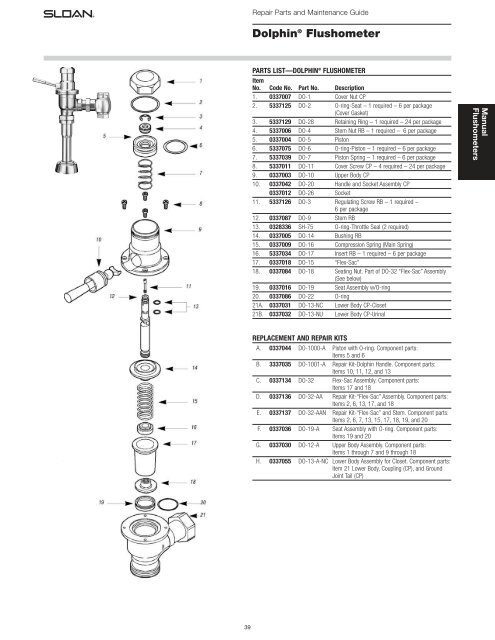
<strong>Dolphin</strong> ® Flushometer<br />
PARTS LIST—DOLPHIN ® FLUSHOMETER<br />
Item<br />
No. Code No. Part No. Description<br />
1. 0337007 DO-1 Cover Nut CP<br />
2. 5337125 DO-2 O-ring-Seat – 1 required – 6 per package<br />
(Cover Gasket)<br />
3. 5337129 DO-28 Retaining Ring – 1 required – 24 per package<br />
4. 5337006 DO-4 Stem Nut RB – 1 required – 6 per package<br />
5. 0337004 DO-5 Piston<br />
6. 5337075 DO-6 O-ring-Piston – 1 required – 6 per package<br />
7. 5337039 DO-7 Piston Spring – 1 required – 6 per package<br />
8. 5337011 DO-11 Cover Screw CP – 4 required – 24 per package<br />
9. 0337003 DO-10 Upper Body CP<br />
10. 0337042 DO-20 Handle and Socket Assembly CP<br />
0337012 DO-26 Socket<br />
11. 5337126 DO-3 Regulating Screw RB – 1 required –<br />
6 per package<br />
12. 0337087 DO-9 Stem RB<br />
13. 0328336 SH-75 O-ring-Throttle Seal (2 required)<br />
14. 0337005 DO-14 Bushing RB<br />
15. 0337009 DO-16 Compression Spring (Main Spring)<br />
16. 5337034 DO-17 Insert RB – 1 required – 6 per package<br />
17. 0337018 DO-15 “Flex-Sac”<br />
18. 0337084 DO-18 Seating Nut. Part of DO-32 “Flex-Sac” Assembly<br />
(See below)<br />
19. 0337016 DO-19 Seat Assembly w/O-ring<br />
20. 0337086 DO-22 O-ring<br />
21A. 0337031 DO-13-NC Lower Body CP-Closet<br />
21B. 0337032 DO-13-NU Lower Body CP-Urinal<br />
Manual<br />
<strong>Flushometers</strong><br />
REPLACEMENT AND REPAIR KITS<br />
A. 0337044 DO-1000-A Piston with O-ring. Component parts:<br />
Items 5 and 6<br />
B. 3337035 DO-1001-A Repair Kit-<strong>Dolphin</strong> Handle. Component parts:<br />
Items 10, 11, 12, and 13<br />
C. 0337134 DO-32 Flex-Sac Assembly. Component parts:<br />
Items 17 and 18<br />
D. 0337136 DO-32-AA Repair Kit-“Flex-Sac” Assembly. Component parts:<br />
Items 2, 6, 13, 17, and 18<br />
E. 0337137 DO-32-AAN Repair Kit-“Flex-Sac” and Stem. Component parts:<br />
Items 2, 6, 7, 13, 15, 17, 18, 19, and 20<br />
F. 0337036 DO-19-A Seat Assembly with O-ring. Component parts:<br />
Items 19 and 20<br />
G. 0337030 DO-12-A Upper Body Assembly. Component parts:<br />
Items 1 through 7 and 9 through 18<br />
H. 0337055 DO-13-A-NC Lower Body Assembly for Closet. Component parts:<br />
Item 21 Lower Body, Coupling (CP), and Ground<br />
Joint Tail (CP)<br />
39
Repair Parts and <strong>Maintenance</strong> <strong>Guide</strong><br />
<strong>Dolphin</strong> ® Flushometer<br />
Manual<br />
<strong>Flushometers</strong><br />
PARTS LIST—DOLPHIN ® FLUSHOMETER MODELS AND VARIATIONS<br />
Item<br />
No. Code No. Part No. Description<br />
1. 0337023 DO-90-AAGNC Closet <strong>Valve</strong> Body and Handle Assembly —<br />
<strong>Dolphin</strong> Type I<br />
0337025 DO-90-AAGNU Urinal <strong>Valve</strong> Body and Handle Assembly —<br />
<strong>Dolphin</strong> Type II<br />
2A. 0388025 H-710-A Bak-Chek ® Control Stop CP with 3/4” NPTF Inlet<br />
for Adjustable Tail<br />
0388022 H-710-A Bak-Chek ® Control Stop CP with 1” NPTF Inlet for<br />
Adjustable Tail<br />
2B. 0388048 NH-710-AG Bak-Chek ® Control Stop with 3/4” NPTF Inlet for<br />
Ground Joint Tail (Naval Brass; use with<br />
Shipboard flushometer Models Type II Class A<br />
and B; requires A-35 Reducer Bushing)<br />
0388058 NH-710-AG Bak-Chek ® Control Stop with 1” NPTF Inlet for<br />
Ground Joint Tail (Naval Brass)<br />
0388044 NH-710-AGS Bak-Chek ® Control Stop with 1” NPSM Inlet for<br />
Ground Joint Tail (Naval Brass; use with<br />
Shipboard flushometer Models Type I and II when<br />
Sil-Braze Adapter is used)<br />
3. 0306196 F-7 1" (25 mm) Supply Flange CP (Supplied When<br />
<strong>Valve</strong> is NOT Ordered with Sweat Solder Kit)<br />
0306191 F-7 3/4" (19 mm) Supply Flange CP (Supplied When<br />
<strong>Valve</strong> is NOT Ordered with Sweat Solder Kit)<br />
4. 3308782 H-633-AA 1" (25 mm) Sweat Solder Kit with Cast Set Screw<br />
Flange CP (“–YBYC” Variation)<br />
3308788 H-636-AA 3/4" (19 mm) Sweat Solder Kit with Cast Set<br />
Screw Flange CP (“–YBYC” Variation)<br />
5A. 0323013 V-500-AA 1-1/2" (38 mm) x 10-1/2" (267 mm) Vacuum<br />
Breaker Assembly CP (Model 110/111)<br />
0323019 V-500-AA 1-1/2" (38 mm) x 23" (534 mm) Vacuum<br />
Breaker Assembly CP (Model 115)<br />
5B1. 0396119 F-101 1-1/2" (38 mm) x 10-1/2" (267 mm) Outlet Tube<br />
CP Type I Class B<br />
5B2. 0306093 F-2-AT Coupling CP with S-30 gasket<br />
5C1. ‡ 0314004 NF-1 1-1/2" (38 mm) Scored Outlet CP (Shipboard<br />
Model, Type I, Class A)<br />
5C2. ‡ 2104180 F-2-AT Coupling CP with S-30 gasket<br />
5D1. 0323010 V-500-A 1-1/2" (38 mm) Vacuum Breaker<br />
Assembly CP (Model 120 does not include<br />
F-2-A Coupling, see Item 5D2 below)<br />
5D2. 0306092 F-2-A Coupling CP with S-30 gasket<br />
5E. ‡ 0306850 NF-29-A Outlet Tube Assembly 3/4" (19 mm) x 6-1/2”<br />
(165 mm) Scored Outlet with 1/2" Offset<br />
(Shipboard Model, Type II, Class A)<br />
5F. 0306849 NF-29-A 3/4" (19 mm) x 6-1/2” (165 mm) Flush Connection<br />
with 1/2" Offset and 3/4" x 1/2" Reducer for<br />
1/2" Spud (Shipboard Model, Type II, Class B)<br />
5G. ‡ 0323004 V-500-AA 3/4" (19 mm) x 10-1/2" (267 mm) Vacuum<br />
Breaker Assembly CP (Model 186)<br />
5H. ‡ 0306780 F-29-A 3/4" (19 mm) x 10-1/2" (267 mm) Flush<br />
Connection CP (Model 186–XYW)<br />
6. † 0396302 F-109 1-1/2" (38 mm) Flush Connection CP<br />
7. SEE SLIP JOINT GASKETS AND RINGS TABLE ON BOTTOM, PAGE 30<br />
7A. 0306146 F-5-AT 1-1/2" (38 mm) Spud Coupling Assembly<br />
(Models 110/111, 115, 120)<br />
7B. 0306125 F-5-AW 3/4" (19 mm) Spud Coupling Assembly<br />
(Model 186)<br />
8. 0306982 F-40 1/2" (13 mm) Sil-Braze Adapter<br />
‡ Cut to proper length at installation. Allow a minimum of 5” (127 mm) between tube ends when using rubber<br />
hose for shock mounted equipment.<br />
† This Outlet Tube is available in various lengths. Consult factory for assistance.<br />
IMPORTANT NOTES<br />
With the exception of the control stop inlet, DO NOT USE pipe sealant or plumbing grease on any valve<br />
component or coupling!<br />
Protect the chrome or special finish of <strong>Sloan</strong> flushometers — DO NOT USE toothed tools to install<br />
or service these valves.<br />
Use a A-50 Super-Wrench or smooth jawed spud wrench to secure all couplings.<br />
40
Repair Parts and <strong>Maintenance</strong> <strong>Guide</strong><br />
<strong>Dolphin</strong> ® Flushometer<br />
PARTS LIST—DOLPHIN ® FLUSHOMETER MODELS AND VARIATIONS<br />
Size Code No. Part No. Description<br />
ITEM 7. Slip Joint Gaskets and Rings<br />
1-1/2” 5306058 F-3 Red Friction Ring<br />
5322001 VBF-5 Black Slip Joint Gasket<br />
0319086/5319086 S-30 Flexible Seat<br />
0319079 S-21 Rigid Seat (rubber over brass)<br />
1-1/2” x 1-1/4” 0396062 F-105 Slip Joint Gasket – Rigid<br />
1-1/4” 5306057 F-3 Red Friction Ring<br />
5322176 VBF-5 Black Slip Joint Gasket<br />
0307052/5307052 G-21 Rigid Seat (rubber over brass)<br />
1” 5306056 F-3 Red Friction Ring<br />
5306115 F-5 Black Slip Joint Gasket<br />
3/4” 5306055 F-3 Red Friction Ring<br />
5306113 F-5 Black Slip Joint Gasket<br />
TROUBLESHOOTING GUIDE<br />
1. Flushometer does not function.<br />
A. Control stop or main valve is closed. Open control stop or main valve.<br />
B. Handle socket assembly is damaged. Replace DO-20 handle socket<br />
assembly.<br />
2. Volume of water is inadequate to siphon fixture.<br />
A. Control stop is not open enough. Adjust control stop for desired<br />
delivery of water volume.<br />
B. Timing of flushometer closure is set too fast. Remove DO-1 cover nut.<br />
Use a small blade screwdriver to turn DO-3 regulating screw<br />
clockwise.<br />
C. Water supply volume or pressure is inadequate. If no gauges are<br />
available to properly measure supply pressure or volume, completely<br />
open control stop and hold down flushometer handle without allowing<br />
it to close. If fixture siphons, increase timing of closure (see previous<br />
solution). If fixture does not siphon, steps must be taken to increase<br />
the supply pressure and/or volume. Contact fixture manufacturer for<br />
minimum water supply requirements of fixture.<br />
3. Flushometer closes immediately.<br />
A. Oil chamber of upper body is empty. Remove DO-1 cover nut. Fill oil<br />
chamber with SAE 10 Oil.<br />
B. Piston seal is worn or damaged. Replace DO-6 piston O-ring seal.<br />
4. Length of flush is too short (short flushing).<br />
A. Volume of oil in oil chamber of upper body is low. Remove DO-1 cover<br />
nut. Fill oil chamber with SAE 10 oil.<br />
B. Timing of flushometer closure is not adequately adjusted. Remove<br />
DO-1 cover nut. Using small blade screwdriver, turn DO-3 regulating<br />
screw clockwise until a satisfactory flush is achieved.<br />
5. Length of flush is too long (long flushing).<br />
A. Timing of flushometer closure not adequately adjusted. Remove DO-1<br />
cover nut. Using small blade screwdriver, turn DO-3 regulating screw<br />
counterclockwise until a satisfactory flush is achieved.<br />
6. Oil is leaking from handle.<br />
A. Stem seals are worn or damaged. Replace two (2) SH-75 throttle seal<br />
O-rings.<br />
7. <strong>Valve</strong> does not close completely (water trickle).<br />
A. Compression spring is worn or damaged. Replace DO-16<br />
compression spring.<br />
B. Flex-sac assembly is worn. Replace DO-15 flex-sac.<br />
Manual<br />
<strong>Flushometers</strong><br />
CARE AND CLEANING INSTRUCTIONS<br />
DO NOT use abrasive or chemical cleaners to clean flushometers, they may<br />
dull the luster and attack the chrome finish. Use ONLY mild soap and water,<br />
and then wipe dry with a clean towel or cloth. When cleaning, protect the<br />
exposed flushometer from any splattering of cleaner. Acids and cleaning<br />
fluids can discolor or remove chrome plating.<br />
When assistance is required, please contact<br />
<strong>Sloan</strong> Technical Support at: 1-888-SLOAN-14 (1-888-756-2614).<br />
41