Project Manual/Specifications - Pavilion Construction
Project Manual/Specifications - Pavilion Construction
Project Manual/Specifications - Pavilion Construction

You also want an ePaper? Increase the reach of your titles
YUMPU automatically turns print PDFs into web optimized ePapers that Google loves.
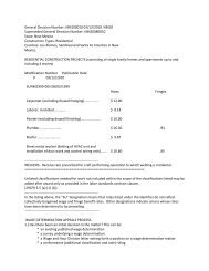
PROJECT Date: 10/05/12<br />
Marquis Newberg<br />
1 - Revised: 12/26/2012 (Design Clarification)<br />
3914 Hayes Street 4 – Revised: 01/25/13 (State Response & Design Clarification)<br />
Newberg, Oregon 97132<br />
OWNER<br />
Marquis Companies<br />
4560 SE International Way, Suite 100<br />
Milwaukie, OR 97222<br />
Contact: Scott Miller<br />
Phone: (971) 206-2330<br />
Fax: (971) 206-5201<br />
DESIGN ARCHITECT<br />
CB| Two Architects<br />
500 Liberty Street SE, Suite 100<br />
Salem, OR 97301<br />
Contact: Matthew Stoffregen<br />
Phone: (503) 480-8700<br />
Fax: (503) 480-8701<br />
Email: matts@cbtwoarchitects.com<br />
GENERAL CONTRACTOR<br />
<strong>Pavilion</strong> <strong>Construction</strong><br />
6720 SW Macadam Ave., Suite 310<br />
Portland, OR 97219<br />
Contact: Tom Sheridan<br />
Phone: (503) 290-5005<br />
Fax: (503) 244-1810<br />
Email: tsheridan@pavilionconstruction.com<br />
LANDSCAPE ARCHITECT<br />
Shapiro Didway Landscape Architecture<br />
1204 SE Water Ave, Suite 11<br />
Portland, OR 97214<br />
Contact: Blair Didway<br />
Phone: (503) 232-0520<br />
Fax: (503) 232-0449<br />
Email: blair@shapiro-la.com
CIVIL ENGINEER<br />
AKS Engineering and Forestry<br />
13910 SW Galreath Drive, Suite 100<br />
Sherwood, OR 97140<br />
Contact: Chuck Gregory<br />
Phone: (503) 925-8799<br />
Fax: (503) 925-8969<br />
E-mail: chuckg@aks-eng.com<br />
GEOTECHNICAL<br />
Geopacific Engineering, Inc.<br />
12115 NW Old Quarry Road<br />
13910 SW Galreath Drive, Suite 100<br />
Sherwood, OR 97140<br />
Contact: James Imbrie and Beth Rapp<br />
Phone: (503) 925-8799<br />
Fax: (503) 925-8969<br />
E-mail: N.A.<br />
KITCHEN<br />
North Star Foodservice Equipment & Design Inc.<br />
9130 SW Pioneer Court, Suite A<br />
Wilsonville, OR 97070<br />
Contact: Mark Weinberg<br />
Phone: (503) 682-1301<br />
Fax: (503) 682-0378<br />
Email: mark@nstaror.com<br />
INTERIOR<br />
Direct Supply Aptura<br />
6767 Industrial Road<br />
Milwaukie, WI 52332<br />
Contact: Brigham Green<br />
Phone: (414) 760-8241<br />
Email: bgreen@directs.com<br />
MECHANICAL, ELECRICAL, AND<br />
PLUMBING ENGINEER<br />
MFIA Consulting Engineers<br />
2007 SE Ash Street<br />
Portland, OR 97214<br />
Contact: James Tormey<br />
Phone: (503) 234-0548<br />
Fax: (503) 234-0677<br />
E-mail: james.tormey@mfia-eng.com<br />
STRUCTURAL ENGINEER<br />
BMGP Engineers, Inc.<br />
1045 13 th Street SE<br />
Salem, OR 97302<br />
Contact: Cameron Carroll<br />
Phone: (503) 399-1399<br />
Fax: (503) 399-8259<br />
E-mail: cameronc@bmgpengineers.com
TOC- 1<br />
TABLE OF CONTENTS<br />
This <strong>Project</strong> <strong>Manual</strong> has been organized under the format of the <strong>Construction</strong> <strong>Specifications</strong> Institute (CSI).<br />
Section numbers are listed merely for identification, and they may not be consecutive. The Contractor shall<br />
check the contents of this <strong>Manual</strong> against the Table of Contents to assure that this volume is complete.<br />
CONTRACTING REQUIREMENTS<br />
00 32 00 GEOTECHNICAL ENGINEERING REPORT<br />
00 62 11 SUBMITTAL TRANSMITTAL – CSI FORM 12.1A<br />
00 63 25 SUBSTITUTION REQUEST FORM – CSI FORM<br />
00 72 00 GENERAL CONDITIONS OF THE CONTRACT FOR CONSTRUCTION<br />
- AIA DOCUMENT A201, 2007 EDITION<br />
DIVISION 1 – GENERAL REQUIREMENTS<br />
01 10 00 SUMMARY<br />
01 13 00 DESIGN-BUILD WORK<br />
01 23 00 ALTERNATES<br />
01 26 00 CONTRACT MODIFICATION PROCEDURES<br />
01 29 00 PAYMENT PROCEDURES<br />
01 31 00 PROJECT MANAGEMENT AND COORDINATION<br />
01 32 00 CONSTRUCTION PROGRESS DOCUMENTATION<br />
01 33 00 SUBMITTAL PROCEDURES<br />
01 40 00 QUALITY REQUIREMENTS<br />
01 42 00 REFERENCES<br />
01 50 00 TEMPORARY FACILITIES AND CONTROLS<br />
01 60 00 PRODUCT REQUIREMENTS<br />
01 70 00 EXECUTION REQUIREMENTS<br />
01 73 29 CUTTING AND PATCHING<br />
01 77 00 CLOSEOUT PROCEDURES<br />
DIVISION 2 – EXISTING CONDITIONS<br />
Not Used<br />
TABLE OF CONTENTS<br />
page 1
TOC- 2<br />
DIVISION 3 – CONCRETE<br />
03 30 00 CAST-IN-PLACE CONCRETE<br />
03 33 19 CONCRETE COLOR SYSTEMS<br />
03 45 00 PRECAST ARCHITECTURAL CONCRETE<br />
DIVISION 4 – MASONRY<br />
04 21 00 BRICK VENEER MASONRY ASSEMBLIES<br />
04 22 00 CONCRETE UNIT MASONRY ASSEMBLIES<br />
DIVISION 5 – METALS<br />
05 12 00 STRUCTURAL STEEL FRAMING<br />
05 50 00 METAL FABRICATIONS<br />
DIVISION 6 - WOOD AND PLASTICS<br />
06 10 00 ROUGH CARPENTRY<br />
06 16 00 SHEATHING<br />
06 17 53 SHOP-FABRICATED WOOD TRUSSES<br />
06 18 13 GLUED-LAMINATED CONSTRUCTION<br />
06 40 13 EXTERIOR ARCHITECTURAL WOODWORK<br />
06 40 23 INTERIOR ARCHITECTURAL WOODWORK<br />
DIVISION 7 - THERMAL AND MOISTURE PROTECTION<br />
07 17 00 BENTONITE WATERPROOFING<br />
07 19 00 WATER REPELLENTS<br />
07 21 00 THERMAL INSULATION<br />
07 27 50 WEATHER RESISTANT BARRIERS AND FLASHINGS<br />
07 31 13 COMPOSITION ROOF SHINGLES<br />
07 46 46 FIBER-CEMENT SIDING<br />
07 54 00 THERMOPLASTIC POLYOLEFIN (TPO) ROOFING<br />
TABLE OF CONTENTS<br />
page 2
TOC- 3<br />
07 62 00 SHEET METAL FLASHING AND TRIM<br />
07 84 13 THROUGH-PENETRATION FIRESTOP SYSTEMS<br />
07 92 00 JOINT SEALANTS<br />
DIVISION 8 - OPENINGS<br />
08 11 13 STEEL DOORS AND FRAMES<br />
08 14 16 FLUSH WOOD DOORS<br />
08 14 33 STILE-AND-RAIL WOOD DOORS<br />
08 31 13 ACCESS DOORS AND FRAMES<br />
08 41 13 ALUMINUM ENTRANCES AND STOREFRONT<br />
08 46 00 AUTOMATIC OPERATING DOORS<br />
08 53 13 VINYL WINDOWS<br />
08 71 00 DOOR HARDWARE<br />
08 71 53 DOOR OPERATION MATRIX AND HARDWARE SCHEDULE<br />
08 88 00 GLAZING<br />
DIVISION 9 – FINISHES<br />
09 10 00 NON-LOAD BEARING STEEL FRAMING & CEILING SUSPENSION SYSTEMS<br />
09 21 16 GYPSUM BOARD ASSEMBLIES<br />
09 30 00 TILE<br />
09 51 13 ACOUSTICAL PANEL CEILINGS<br />
09 65 13 RESILIENT WALL BASE AND ACCESSORIES<br />
09 65 16 RESILIENT SHEET FLOORING<br />
09 65 19 RESILIENT TILE FLOORING<br />
09 68 13 TILE CARPETING<br />
09 68 16 BROADLOOM CARPETING<br />
09 75 00 STONE FACING<br />
09 77 00 FRP WALL PANELS<br />
09 91 00 PAINTING<br />
TABLE OF CONTENTS<br />
page 3
TOC- 4<br />
DIVISION 10 – SPECIALTIES<br />
10 14 00 SIGNAGE<br />
10 26 00 WALL PROTECTION<br />
10 28 00 TOILET AND BATH ACCESSORIES<br />
10 31 00 MANUFACTURED FIREPLACE<br />
10 44 00 FIRE-PROTECTION SPECIALTIES<br />
10 51 00 METAL LOCKERS<br />
10 75 00 FLAGPOLE<br />
10 90 00 CLOSET SPECIALTIES<br />
DIVISION 11 – EQUIPMENT<br />
11 31 00 RESIDENTIAL APPLIANCES<br />
11 40 00 FOOD SERVICE EQUIPMENT<br />
DIVISION 12 – FURNISHINGS<br />
12 32 13 MANUFACTURED CASEWORK<br />
12 48 13 ENTRANCE MATS AND FRAMES<br />
12 93 00 SITE FURNISHINGS<br />
DIVISION 13 – SPECIAL CONSTRUCTION<br />
Not Used<br />
DIVISION 14 – 20<br />
Not Used<br />
DIVISION 21 - FIRE SUPPRESSION<br />
21 00 00 BASIC FIRE PROTECTION DESIGN BUILD REQUIREMENTS<br />
21 01 00 BASIC FIRE PROTECTION MATERIALS AND METHODS<br />
21 06 10 SCHEDULES FOR WATER-BASED FIRE SUPPRESSION PIPING AND EQUIPMENT<br />
21 13 00 FIRE SUPPRESSION SPRINKLER SYSTEMS<br />
TABLE OF CONTENTS<br />
page 4
TOC- 5<br />
DIVISION 22 - PLUMBING<br />
22 05 00 COMMON PLUMBING MATERIALS AND METHODS<br />
22 07 00 PLUMBING INSULATION<br />
22 10 00 PLUMBING PIPING<br />
22 30 00 PLUMBING EQUIPMENT<br />
22 40 00 PLUMBING FIXTURES<br />
22 47 00 DRINKING FOUNTAINS AND WATER COOLERS<br />
DIVISION 23 - HEATING, VENTILATING, AND AIR CONDITIONING<br />
23 05 00 HVAC MATERIALS AND METHODS<br />
23 05 90 TESTING, ADJUSTING AND BALANCING<br />
23 07 00 HVAC INSULATION<br />
23 10 00 FACILITY FUEL SYSTEMS<br />
23 23 00 REFRIGERANT PIPING SYSTEM<br />
23 30 00 AIR DISTRIBUTION<br />
23 34 00 HVAC FANS<br />
23 54 00 FURNACES<br />
23 60 00 COOLING EQUIPMENT<br />
23 74 00 PACKAGED HVAC UNITS<br />
23 80 00 TERMINAL HVAC EQUIPMENT<br />
DIVISIONS 24 - 25<br />
Not Used<br />
DIVISION 26 – ELECTRICAL<br />
26 05 00 COMMON WORK RESULTS FOR ELECTRICAL<br />
26 05 19 ELECTRICAL POWER CONDUCTORS AND CABLES<br />
26 05 20 NONMETALLIC-SHEATHED CABLE<br />
TABLE OF CONTENTS<br />
page 5
TOC- 6<br />
26 05 21 METAL-CLAD CABLE<br />
26 05 26 GROUNDING AND BONDING FOR ELECTRICAL SYSTEMS<br />
26 05 29 HANGERS AND SUPPORTS FOR ELECTRICAL SYSTEMS<br />
26 05 33 RACEWAY AND BOXES FOR ELECTRICAL SYSTMES<br />
26 05 53 IDENTIFICATION FOR ELECTRICAL SYSTEMS<br />
26 05 73 ELECTRICAL POWER SYSTEM STUDIES<br />
26 07 40 TELEPHONE AND COMPUTER DATA PROVISIONS<br />
26 09 20 LIGHTING CONTROL SYSTEM<br />
26 09 23 LIGHTING CONTROL DEVICES<br />
26 20 00 SERVICE ENTRANCE<br />
26 22 00 TRANSFORMERS<br />
26 24 13 SWITCHBOARDS<br />
26 24 16 PANELBOARDS<br />
26 27 26 WIRING DEVICES<br />
26 28 00 CIRCUIT PROTECTIVE DEVICES<br />
26 32 13 DIESEL-ENGINE-DRIVEN GENERATOR SETS<br />
26 36 23 AUTOMATIC TRANSFER SWITCHES<br />
26 43 13 TRANSIENT-VOLTAGE SUPPRESSION<br />
26 50 00 LIGHTING<br />
DIVISIONS 27<br />
27 00 00 PROJECT OVERVIEW<br />
27 01 00 BASIC COMMUNICATIONS REQUIREMENTS<br />
27 01 30 ADMINISTRATIVE REQUIREMENTS<br />
27 01 70 TESTING, IDENTIFICATIONS, AND ADMINISTRATION<br />
27 01 80 TECHNOLOGY DOCUMENTATION<br />
27 01 90 SUPPORT AND WARRANTY<br />
27 05 30 INTERIOR COMMUNICATIONS PATHWAYS<br />
TABLE OF CONTENTS<br />
page 6
TOC- 7<br />
27 11 13 ENTRANCE FACILITIES<br />
27 11 16 EQUIPMENT AND TELECOMMUNICATION ROOMS<br />
27 15 00 HORIZONTAL COPPER CABLING<br />
27 51 13 SIMPLE PAGING SYSTEMS<br />
DIVISIONS 28<br />
28 00 10 BASIC REQUIREMENTS<br />
28 13 00 CARD ACCESS<br />
28 31 00 FIRE ALARM AND DETECTION SYSTEM<br />
DIVISION 29 – 30<br />
Not Used<br />
DIVISION 31 - EARTHWORK<br />
31 05 13 EARTHWORK<br />
31 25 13 EROSION CONTROLS<br />
DIVISION 32 - EXTERIOR IMPROVEMENTS<br />
32 11 23 AGGREGATE BASE COURSES<br />
32 12 16 ASPHALT PAVING<br />
32 13 13 RIGID PAVEMENT CONCRETE CURBS AND WALKS<br />
32 31 20 DECORATIVE FENCES AND GATES<br />
32 84 00 IRRIGATION<br />
32 93 00 PLANTS<br />
DIVISION 33 – UTILITIES<br />
33 05 13 MANHOLES & STRUCTURES<br />
33 11 16 SITE WATER UTILITY DISTRIBUTION PIPING<br />
33 31 00 SANITARY UTILITY SEWAGE PIPING<br />
TABLE OF CONTENTS<br />
page 7
TOC- 8<br />
33 41 00 STORM UTILITY DRAINAGE PIPING<br />
APPENDIX<br />
00 32 00A GEOTECHNICAL ENGINEERING REPORT<br />
00 62 11A SUBMITTAL TRANSMITTAL – CSI FORM 12.1A<br />
00 63 25A SUBSTITUTION REQUEST FORM – CSI FORM<br />
00 72 00A GENERAL CONDITIONS OF THE CONTRACT FOR CONSTRUCTION<br />
- AIA DOCUMENT A201, 2007 EDITION<br />
01 77 00A PUNCH LIST – CSI FORM 14.1A<br />
08 71 53A DOOR OPERATION MATRIX AND HARDWARE SCHEDULE<br />
END OF SECTION<br />
TABLE OF CONTENTS<br />
page 8
MARQUIS Newberg<br />
00 32 00 GEOTECHNICAL ENGINEERING REPORT<br />
October 5, 2012<br />
PART 1 - GENERAL<br />
1.1 The Geotechnical Engineering Report is part of this Specification. See Appendix.<br />
END OF SECTION<br />
00 32 00 –GEOTECHNICAL ENGINEERING REPORT<br />
page 1
MARQUIS Newberg<br />
00 62 11 – SUBMITTAL TRANSMITTAL<br />
October 5, 2012<br />
PART 1 - GENERAL<br />
1.1 “Submittal Transmittal”, CSI Form 12.1A is part of this Specification. See Appendix.<br />
END OF SECTION<br />
00 62 11 – SUBMITTAL TRANSMITTAL<br />
page 1
MARQUIS Newberg<br />
00 63 25 SUBSTITUTION REQUEST<br />
June 15, 2012<br />
PART 1 - GENERAL<br />
1.1 “Substitution Request”, CSI Form 13.1A is part of this Specification. See Appendix.<br />
END OF SECTION<br />
00 63 25 – SUBSTITUTION REQUEST<br />
page 1
MARQUIS Newberg<br />
00 72 00 GENERAL CONDITIONS OF THE CONTRACT FOR CONSTRUCTION<br />
June 15, 2012<br />
PART 1 - GENERAL<br />
1.1 “General Conditions of the Contract for <strong>Construction</strong>”, AIA Document A201, 2007 edition is part of<br />
this Specification. See Appendix.<br />
END OF SECTION<br />
00 72 00 – GENERAL CONDITIONS OF THE CONTRACT FOR CONSTRUCTION<br />
page 1
MARQUIS Newberg<br />
01 10 00 - SUMMARY<br />
October 5, 2012<br />
PART 1 - GENERAL<br />
1.1 WORK COVERED BY CONTRACT DOCUMENTS<br />
A. <strong>Project</strong> Identification:<br />
1. <strong>Project</strong> consists of health-care occupancies in single-story building, as follows:<br />
a. Skilled Nursing Facility (SN):<br />
1) 37 units (54 beds) on First level.<br />
2) 33,503 square feet.<br />
3) Includes associated common use areas, food service, and offices.<br />
4) Type V - A.<br />
5) Fully sprinklered.<br />
b. Parking:<br />
1) 55 spaces all on grade.<br />
c. Sitework<br />
1) Concrete paving, including stairs and ramps.<br />
2) Asphalt paving.<br />
3) Patio paving.<br />
4) Plants, trees, and sod.<br />
5) Water features (Low Impact Development Approaches water quality swales).<br />
6) Site-built improvements, including benches and planters.<br />
7) Site furnishings.<br />
2. <strong>Project</strong> Location:<br />
a. 3914 Hayes Street<br />
Newberg, OR 97132<br />
3. Owner:<br />
Marquis Companies<br />
4560 SE International Way<br />
Suite 100<br />
Milwaukie, OR 97222<br />
971.206.2330<br />
contact: Scott Miller<br />
smiller@marquiscompanies.com<br />
B. Owner's Representative:<br />
<strong>Construction</strong> Management Group, Inc. (CMG)<br />
5131 SW Idaho Street<br />
Portland, OR 97221<br />
503.289.1182<br />
contact: Graeme Leggatt, JR<br />
constructionmg@hotmail.com<br />
C. Architect Identification:<br />
1. The Contract Documents, dated October 5, 2012 were prepared for <strong>Project</strong> by:<br />
CB│Two Architects<br />
500 Liberty Street SE<br />
Suite 100<br />
Salem, OR 97301<br />
503.480.8700<br />
contact: Matthew Stoffregen<br />
matts@CBTwoarchitects.com<br />
01 10 00 - SUMMARY<br />
page 1
MARQUIS Newberg<br />
01 10 00 - SUMMARY<br />
October 5, 2012<br />
D. General Contractor Identification:<br />
1. Sub-bidders report to:<br />
<strong>Pavilion</strong> <strong>Construction</strong><br />
6720 SW Macadam Avenue<br />
Suite 310<br />
Portland, OR 97219<br />
503.290.5005<br />
contact: Tom Sheridan<br />
tsheridan@pavilionconstruction.com<br />
E. The Work includes the following specialties:<br />
1. Site utilities.<br />
2. Cast-in-place concrete paving<br />
3. Landscaping and irrigation systems on-grade and above-grade.<br />
4. Site security fencing.<br />
5. Cast-in-place concrete.<br />
6. Concrete unit masonry and brick veneer.<br />
7. Limited structural steel framing.<br />
8. Miscellaneous Metal fabrications.<br />
9. Wood framing, including manufactured trusses and glued-laminated beams.<br />
10. Casework.<br />
11. Fiber-cement siding.<br />
12. TPO membrane roofing assembly and composition shingle roofing.<br />
13. Standard steel doors and frames.<br />
14. Flush wood doors and stile-and-rail wood doors.<br />
15. Aluminum entrance and storefront system.<br />
16. Vinyl windows.<br />
17. Security access systems.<br />
18. Ceramic and quarry tile.<br />
19. Composite wood flooring, resilient sheet and tile flooring.<br />
20. Tile and broadloom carpeting.<br />
21. Fabric and stone wall facings.<br />
22. Residential appliances and food service equipment.<br />
23. Exterior and interior signage.<br />
24. Toilet accessories.<br />
25. Manufactured fireplaces.<br />
26. Commercial laundry equipment.<br />
27. Nurse call system.<br />
28. Monument signs.<br />
1.2 CONTRACT<br />
A. <strong>Project</strong> will be constructed in one phase, under a general construction contract.<br />
B. Start Date:<br />
1. Start work within 10 calendar days following Notice to Proceed.<br />
C. See Appendix and Division 0 documents for additional terms and requirements.<br />
1.3 USE OF PREMISES<br />
A. General:<br />
1. Contractor shall have full use of premises for construction operations, including use of <strong>Project</strong> site,<br />
during construction period.<br />
2. Contractor's use of premises is limited only by Owner's right to occupy completed portions of the<br />
<strong>Project</strong> or perform work on portions of <strong>Project</strong>.<br />
01 10 00 - SUMMARY<br />
page 2
MARQUIS Newberg<br />
01 10 00 - SUMMARY<br />
October 5, 2012<br />
1.4 WORK RESTRICTIONS<br />
A. Existing Utility Interruptions:<br />
1. Do not interrupt utilities serving facilities occupied by Owner or adjacent property owners unless<br />
permitted under the following conditions, and then only after arranging to provide temporary utility<br />
services according to requirements indicated:<br />
a. Notify Owner or owners of adjacent properties not less than two days in advance of<br />
proposed utility interruptions.<br />
b. Do not proceed with utility interruptions without Owner's or adjacent owners' written<br />
permission.<br />
1.5 PARTIAL OWNER OCCUPANCY DURING CONSTRUCTION<br />
A. Owner reserves the right to place and install equipment in completed areas before Substantial Completion.<br />
1. Such placement of equipment and partial occupancy shall not constitute acceptance of the total<br />
Work.<br />
1.6 OWNER OCCUPANCY AT SUBSTANTIAL COMPLETION<br />
A. Prior to Owner occupancy, prepare a Certificate of Substantial Completion for areas listed below and any<br />
adjacent circulation and service areas identified by Owner.<br />
1. Obtain Certificate of Occupancy from authorities having jurisdiction.<br />
2. Before partial Owner occupancy, ensure that:<br />
a. Mechanical and electrical systems are fully operational.<br />
b. Required tests and inspections have been successfully completed.<br />
B. On occupancy, Owner will:<br />
1. Operate and maintain mechanical and electrical systems serving occupied portions of building.<br />
2. Assume responsibility for maintenance and custodial service for occupied portions of building.<br />
1.7 INDOOR AIR QUALITY MEASURES<br />
A. Ventilation System Protection:<br />
1. HVAC during <strong>Construction</strong>:<br />
a. Do not run HVAC system serving occupied portions of building without prior written approval<br />
of Owner.<br />
b. Seal new ductwork intake and exhaust vents to prevent contamination from dust, moisture,<br />
and chemical contamination.<br />
c. Store HVAC equipment in a clean, dry location.<br />
d. Seal all HVAC inlets and outlets.<br />
e. Seal HVAC components during installation.<br />
2. Filtration during <strong>Construction</strong>:<br />
a. Use a temporary ventilation system in areas of construction.<br />
b. Use temporary filtration media.<br />
1) Use temporary filtration media with Minimum Efficiency Reporting Value [MERV] of 8<br />
as determined by ASHRAE 52.2-1999) on any return air systems operational during<br />
<strong>Construction</strong>.<br />
c. Replace all filtration media immediately prior to occupancy.<br />
1) Install permanent filtration media shall be equal to the standard filter installed by the<br />
manufacturer as original equipment.<br />
d. Clean air plenums before closing them in.<br />
01 10 00 - SUMMARY<br />
page 3
MARQUIS Newberg<br />
01 10 00 - SUMMARY<br />
October 5, 2012<br />
e. Inspect filters regularly.<br />
B. Microbial And Fungal Contamination Prevention<br />
1. Perform, schedule, and sequence Work to limit conditions supporting formation of microbes, molds,<br />
and fungi.<br />
a. Ensure that construction assembly details will not result in moisture intrusion.<br />
b. Protect on-site stored and installed absorptive materials (such as insulation, drywall, and<br />
wood) from moisture damage, and from contamination by construction dust, debris, and<br />
fumes during all phases of <strong>Construction</strong>, both before and after installation.<br />
c. Control water penetration, dampness, and humidity to protect products not treated or<br />
indicated by manufacturer for exterior use.<br />
d. Do not install moisture-damaged materials.<br />
e. When visible microbial, mold ,and fungal formations are observed, promptly contact Owner<br />
and Architect for determination by hygienist employed by Owner.<br />
f. Clean non-absorbent materials using low hazard cleaners accepted by Owner and Architect.<br />
g. Remove and replace affected materials that cannot be completely cleaned by non-abrasive<br />
surface treatments.<br />
h. Remove and replace affected materials identified by Owner's hygienist as being food<br />
sources for microbes, molds, and fungi.<br />
i. Remove interior products and finishes identified as food sources, that have absorbed<br />
sufficient moisture to become damp, and are not immediately made dry, whether or not<br />
microbial, mold, or fungal growth is observed, including:<br />
1) Gypsum board.<br />
2) Organic materials composed of cellulose fiber or paper.<br />
3) Materials containing sucrose or other binders and glues identified as supporting<br />
microbial growth.<br />
4) Fibrous insulation materials including duct liner, fiberglass insulation, and mineral<br />
fiber.<br />
5) Mechanical ductwork.<br />
6) Wood: Lumber and engineered products.<br />
a) Reduce moisture content of wood products when measurement by a moisture<br />
meter exceeds 19-percent moisture content..<br />
j. Remove from construction site wood- and cellulose-based products showing signs of<br />
mildew, including in-place construction not accepted by Owner’s hygienist.<br />
k. Promptly correct conditions supporting or subject to become an environment supporting<br />
microbial, mold, or fungal growth.<br />
l. Repair conditions leading to moisture condensation and water penetration.<br />
m. Do not permit conditions leading to standing water.<br />
C. Pollution Source Control<br />
1. Use low-emitting products specified in technical sections.<br />
a. Draft and adopt Materials Control Measures to ensure installed products meet requirements<br />
for low- or zero-emissions.<br />
b. Implement strategies to prevent tracking pollutants into areas of Work.<br />
2. Allow high-VOC materials to off-gas prior to installation.<br />
a. Allow dry furnishings and materials, including the following, to “air-out” in clean<br />
environments prior to installation.<br />
1) Carpet.<br />
2) Resilient flooring.<br />
3) Ceiling panels and tiles.<br />
4) Textiles.<br />
5) Furniture.<br />
6) Wood shelving.<br />
01 10 00 - SUMMARY<br />
page 4
MARQUIS Newberg<br />
01 10 00 - SUMMARY<br />
October 5, 2012<br />
3. Wet Materials:<br />
a. While still complying with manufacturer’s warrantee requirements, use minimal amounts of<br />
"wet" materials including the following:<br />
1) Adhesives.<br />
2) Sealants.<br />
3) Glazes.<br />
4) Coatings.<br />
5) Paints.<br />
D. Pollutant Pathway Interruption<br />
1. Use an air barrier or pressure differential to isolate areas at different stages of completion.<br />
E. Housekeeping<br />
1. Dust Control:<br />
a. Confine dust-generating activities to indicated area of Work.<br />
b. Promptly clean up dust and other potential airborne contaminants as they are generated.<br />
c. Provide worker protection.<br />
d. Keep areas of Work dry and promptly clean up all spills.<br />
e. Keep containers of volatile liquids covered when not in use.<br />
f. Do not allow accumulations of sawdust, dust, rags, debris, and carbon-based materials and<br />
materials emitting fumes and odors to accumulate within concealed construction, including<br />
within stud spaces and wall cavities.<br />
1) Remove and clean prior to enclosing behind permanent construction.<br />
g. Vacuum carpet, upholstery, and other porous materials throughout building using a highefficiency<br />
particulate arrestor HEPA filter vacuum cleaner just prior to Substantial<br />
Completion.<br />
1) Replace and dispose of vacuum bags when bag is half full.<br />
F. Scheduling for Air Quality Management<br />
1. Account for curing time and off-gassing when scheduling construction activities.<br />
2. Prior to installing interior materials and finishes, enclose areas of renovation and new construction:<br />
a. Control humidity.<br />
b. Ventilate.<br />
c. Make watertight.<br />
3. Allow furnishings and materials to air out as in Article 1.6 C 2 above.<br />
4. Install porous materials only after closing in the building.<br />
5. Allow sufficient time for Work generating significant moisture to dry and cure before installing<br />
materials that may attract and retain moisture, including:<br />
a. Carpet.<br />
b. Acoustical materials.<br />
c. Textiles.<br />
6. Provide adequate ventilation during curing period.<br />
a. Provide supplemental (spot) ventilation for at least 72 hours after Work is completed.<br />
1) HVAC system operation : Supply air fans and ducts only, with exhaust provided<br />
through windows.<br />
2) Use exhaust fans to pull exhaust air from deep interior locations.<br />
3) Use paths to exterior during this process.<br />
G. Remedial Action<br />
1. Promptly take action to inspect and remediate conditions suspected of supporting biological,<br />
particulate, and chemical indoor air pollution.<br />
a. Identify, stop, and repair causes of uncontrolled water penetration into building.<br />
01 10 00 - SUMMARY<br />
page 5
MARQUIS Newberg<br />
01 10 00 - SUMMARY<br />
October 5, 2012<br />
b. Where contamination by hazardous chemicals, microbes, or fungi is suspected, promptly<br />
notify and consult with Owner and Architect, prior to beginning removal of contaminated<br />
material.<br />
1.8 OWNER-FURNISHED, CONTRACTOR-INSTALLED ITEMS<br />
A. No items in this category are anticipated; but should Owner opt to furnish items during the <strong>Construction</strong><br />
phase, proceed as follows:.<br />
1. Coordinate with Owner's suppliers of material and equipment to be incorporated into the Work.<br />
2. Owner will arrange and pay for delivery of Owner-furnished items according to Contractor's<br />
<strong>Construction</strong> Schedule.<br />
3. After delivery, Owner will inspect delivered items for damage.<br />
a. Assist in Owner's inspection.<br />
4. If Owner-furnished items are damaged, defective, or missing, Owner will arrange for replacement.<br />
5. Owner will arrange for manufacturer's field services and for delivery of manufacturer's warranties to<br />
Contractor.<br />
6. Owner will furnish Contractor the earliest possible delivery date for Owner-furnished products.<br />
a. Using Owner-furnished earliest possible delivery dates, designate delivery dates of Ownerfurnished<br />
items in Contractor's <strong>Construction</strong> Schedule.<br />
b. Review Shop Drawings, Product Data, and Samples and return them to Architect noting<br />
discrepancies or anticipated problems in use of product.<br />
c. If Owner-furnished items are damaged as a result of Contractor's operations, Contractor<br />
shall repair or replace them.<br />
1.9 SPECIFICATION FORMATS AND CONVENTIONS<br />
A. Specification Format:<br />
1. Sections in the <strong>Project</strong> <strong>Manual</strong> are in numeric sequence; however, the sequence is incomplete.<br />
2. Consult the Table of Contents at the beginning of the <strong>Project</strong> <strong>Manual</strong> to determine numbers and<br />
names of sections in the Contract Documents.<br />
B. Specification Content:<br />
1. The <strong>Specifications</strong> use conventions for the intended meaning of certain terms and phrases.<br />
2. These conventions include:<br />
a. Abbreviated Language:<br />
1) Infer words implied, but not stated, as the sense requires.<br />
2) Interpret singular as plural, and plural words as singular.<br />
b. Requirements expressed in the imperative mood (e.g. "Install equipment . . .") are to be<br />
performed by Contractor.<br />
1) The indicative or subjunctive mood (e.g. "Equipment shall be installed . . .") may be<br />
used to describe responsibilities that must be fulfilled indirectly by Contractor or by<br />
others.<br />
c. The words "shall," "shall be," or "shall comply with," depending on the context, are implied<br />
where a colon (:) is used within a sentence or phrase.<br />
C. See Division 1 Section "References" for additional <strong>Specifications</strong> terminology.<br />
PART 2 - PRODUCTS (Not Used)<br />
01 10 00 - SUMMARY<br />
page 6
MARQUIS Newberg<br />
01 10 00 - SUMMARY<br />
October 5, 2012<br />
PART 3 - EXECUTION (Not Used)<br />
END OF SECTION<br />
01 10 00 - SUMMARY<br />
page 7
MARQUIS Newberg<br />
01 13 00 - DESIGN-BUILD WORK<br />
October 5, 2012<br />
PART 1 - GENERAL<br />
1.1 SUMMARY<br />
A. Section Includes:<br />
1. Administrative and coordination requirements for performing those components of the Work that<br />
are designed and built by the Contractor or its subcontractor(s).<br />
2. General project coordination procedures.<br />
B. Related Sections:<br />
1. Division 1 Section “Summary”.<br />
2. Division 1 Section “<strong>Project</strong> Management and Coordination”<br />
3. Division 1 Section “Submittal Procedures”.<br />
4. Division 1 Section “Product Requirements”.<br />
5. Division 1 Section “Execution Requirements”.<br />
6. Division 1 Section "Closeout Procedures" for submittal of Record Drawings.<br />
7. Division 2 – 33 sections specifying design/build components (See Schedule in Part 3 below).<br />
C. See Appendix and Division 0 documents for additional terms and requirements.<br />
1.2 DEFINITION<br />
A. Design-Build Work Items:<br />
1. Portions of the Work indicated in the Contract Documents to be performed by the Contractor on a<br />
“design-build” basis.<br />
2. The Contractor, rather than the Architect, is solely responsible for:<br />
a. The design of such systems.<br />
b. The coordination of the design-build subcontractors, who shall be the engineers of record<br />
for such systems.<br />
c. The coordination of design-build work with the Architect’s design.<br />
d. The determination of, and compliance with, requirements by local jurisdiction for such<br />
systems.<br />
e. Submittal preparation and presentation to local jurisdiction for approval (permit process).<br />
B. Work of This Section may be identified elsewhere in Documents as any of the following:<br />
1. "Bidder-Designed".<br />
2. "Deferred Design".<br />
3. "Deferred Submittal".<br />
1.3 SUBMITTALS<br />
A. General Requirements:<br />
1. Review of design-build submittals by the Architect or its consultants does not constitute acceptance<br />
of the design-build system, and does not diminish the responsibility of the design-build contractor<br />
and its subcontractors as "Engineers of Record”.<br />
B. Product Data, Shop Drawings, Samples, and Calculations:<br />
1. Submittals which describe the design-build work will be reviewed by the Architect in a cursory<br />
manner, and solely for the purpose of assessing the aesthetic aspects of such designs.<br />
2. Review of submittals by the Architect’s consultants is solely for the purpose of evaluating general<br />
compliance with the performance requirements specified.<br />
01 13 00 - DESIGN-BUILD WORK<br />
page 1
MARQUIS Newberg<br />
01 13 00 - DESIGN-BUILD WORK<br />
October 5, 2012<br />
C. Quality Control Submittals:<br />
1. For each product or system specifically assigned to Contractor to be designed or certified by a<br />
design professional:<br />
a. Submit a statement signed and sealed by the design professional responsible, indicating<br />
that the products and systems comply with indicated performance and design requirements.<br />
b. Include building code references, design loads, and other factors used to design or certify<br />
design-build products and systems.<br />
2. If required, submit calculations, prepared and signed by a professional engineer licensed in the<br />
State of Oregon.<br />
3. Review by the Architect or its consultants of calculations, drawings, test reports, and certificates<br />
that are required by the Contract Documents to have professional certification is solely to ensure<br />
compliance with design-build submittal requirements.<br />
a. The adequacy, accuracy and completeness of the calculations, drawings and certificates<br />
remain the Contractor's responsibility.<br />
D. Coordination Drawings:<br />
1. If requested, submit Coordination Drawings showing the relationship of design-build components to<br />
the rest of the Work, including:<br />
a. Utility connections.<br />
b. Structural supports.<br />
c. Manufactured components.<br />
d. <strong>Construction</strong> previously installed.<br />
2. Dimensions and location of design-build work.<br />
3. Installation requirements to be accomplished by others for design-build work, including:<br />
a. Utility connections.<br />
b. Structural supports.<br />
c. Installation and operating clearances.<br />
d. Required installation sequences.<br />
4. See Divisions 21, 22, 23, 26, and 33 for Coordination Drawings requirements for mechanical and<br />
electrical installations.<br />
E. Other Submittals:<br />
1. Submit warranties, maintenance instructions, and other informational submittals specified for each<br />
item of design-build work.<br />
1.4 QUALITY ASSURANCE<br />
A. Requirements and Standards:<br />
1. Perform design-build work to comply with:<br />
a. Reference standards indicated.<br />
b. Performance requirements indicated.<br />
c. Regulatory requirements applicable to the particular design-build work item.<br />
B. Design Professional Qualifications:<br />
1. Where compliance with performance requirements necessitates calculations by a design<br />
professional, the design professional:<br />
a. Must be licensed in the State of Oregon, and<br />
b. Must carry professional liability insurance acceptable to the Owner.<br />
C. Cost of changes to Architect’s design necessitated by design of design-build work items is the<br />
responsibility of the Contractor.<br />
D. Instruct subcontractors to verify installation space requirements prior to submittal of Design-Build<br />
documents.<br />
01 13 00 - DESIGN-BUILD WORK<br />
page 2
MARQUIS Newberg<br />
01 13 00 - DESIGN-BUILD WORK<br />
October 5, 2012<br />
E. Mock-ups:<br />
1. If required by the specification sections describing the items of design-build work, construct mockups<br />
or field samples, which will be reviewed by the Architect for compliance with visual or<br />
workmanship requirements only.<br />
2. See Division 1 Sections "Quality Requirements" and "Execution Requirements"; and technical<br />
sections specifying materials included in mock-ups, for additional data regarding mock-ups.<br />
1.5 PROJECT CONDITIONS<br />
A. Field Measurements:<br />
1. Where design-build work is indicated to fit to other construction, check actual dimensions of other<br />
construction by accurate field measurements before fabrication.<br />
2. Show recorded measurements on Coordination and Shop Drawings.<br />
3. Coordinate fabrication schedule with construction progress to avoid delaying the Work.<br />
PART 2 - PRODUCTS<br />
Not used<br />
PART 3 - EXECUTION<br />
A. Division 03 Sections:<br />
1. Section 03 30 00: "Cast-in-Place Concrete".<br />
a. Design of formwork.<br />
2. Section 03 45 00: "Precast Architectural Concrete".<br />
B. Division 05 Sections:<br />
1. Section 05 50 00: "Metal Fabrications".<br />
C. Division 06 Section:<br />
1. Section 06 17 53: "Shop-Fabricated Wood Trusses".<br />
D. Division 07 Sections:<br />
1. Section 07 84 13: “Through-Penetration Firestop Systems”.<br />
E. Division 08 Section:<br />
1. Section 08 41 13: “Aluminum Entrances and Storefront”.<br />
2. Section 08 71 00: "Door Hardware".<br />
F. Division 09 Sections:<br />
1. Section 09 2116: “Gypsum Board Assemblies”.<br />
a. Seismic bracing of partitions not extended to structure.<br />
2. Section 09 51 13: "Acoustical Panel Ceilings".<br />
a. Seismic bracing to structure.<br />
3. Section 09 75 00: "Stone Facing".<br />
a. Engineer anchorage of stone within substrate.<br />
G. Division 10 Section:<br />
a. Section 10 75 00: "Flagpole".<br />
01 13 00 - DESIGN-BUILD WORK<br />
page 3
MARQUIS Newberg<br />
01 13 00 - DESIGN-BUILD WORK<br />
October 5, 2012<br />
H. Division 21 - Fire Suppression.<br />
I. Division 27 – Communications.<br />
J. Division 28 – Electronic Safety and Security.<br />
END OF SECTION<br />
01 13 00 - DESIGN-BUILD WORK<br />
page 4
MARQUIS Newberg<br />
01 23 00 - ALTERNATES<br />
October 5, 2012<br />
PART 1 - GENERAL<br />
1.1 SUMMARY<br />
A. This Section includes procedural requirements for Alternates.<br />
1.2 DEFINITIONS<br />
A. Alternate:<br />
1. An amount stated on the statement of <strong>Construction</strong> Cost for certain work defined in the Bidding<br />
Requirements that may be added to or the <strong>Construction</strong> Cost.<br />
2. The amount is added if Owner decides to accept a corresponding change in:<br />
a. The amount of construction to be completed; OR<br />
b. The products, materials, equipment, systems, or installation methods described in the<br />
Contract Documents.<br />
3. The cost or credit for each alternate is the net addition to the Contract Cost: No other adjustments<br />
are made to the Contract Cost.<br />
1.3 OWNER'S PROCEDURE<br />
A. The alternates described in this Section may be exercised at the option of the Owner within 30 days of the<br />
Contractor's written notice to Owner that decision on an alternate is required.<br />
B. The Owner reserves the right to accept the alternates without regard to order or sequence.<br />
1. Such acceptance shall not impair the selection of a low, responsible and responsive bidder to<br />
whom the Contract may be awarded under an equitable bid procedure.<br />
1.4 CONTRACTOR PROCEDURE<br />
A. Itemize on the Contractor's Statement of <strong>Construction</strong> Costs alternates specified in This Section.<br />
B. Clarification:<br />
1. If there is a question regarding the extent, scope, nature, or intent of alternates, request clarification<br />
from the Owner's Authorized Representative.<br />
2. Failure on the part of the Contractor to clarify any unclear items does not relieve the Contractor of<br />
responsibility for the selected alternates in accordance with the intent and requirements of the<br />
<strong>Project</strong> <strong>Manual</strong> and Drawings.<br />
C. Coordination:<br />
1. Modify or adjust adjacent work as necessary to completely integrate the alternate into <strong>Project</strong>.<br />
2. Include as part of each alternate:<br />
a. Costs of adjustments to other trades, which may be required to achieve the intent of the<br />
selected alternate.<br />
b. Miscellaneous devices, accessories, and other items incidental to or required for a complete<br />
installation whether or not indicated as part of alternate.<br />
D. Notification:<br />
1. Immediately following Award of the Contract, notify each party involved, in writing, of the status of<br />
each alternate.<br />
2. Include a complete description of negotiated modifications to alternates.<br />
01 23 00 - ALTERNATES<br />
page 1
MARQUIS Newberg<br />
01 23 00 - ALTERNATES<br />
October 5, 2012<br />
E. Execute accepted alternates under the same conditions as other work of the Contract.<br />
F. Schedule:<br />
1. A Schedule of Alternates is included at the end of this Section.<br />
2. Specification Sections referenced in schedule contain requirements for achieving each alternate.<br />
G. See Appendix and Division 0 documents for additional terms and requirements.<br />
1.5 QUALITY ASSURANCE<br />
A. The description of the alternates in the Schedule of Alternates below is qualitative and not quantitative.<br />
B. Determine the quantities and extent of labor and materials required to execute alternates selected by the<br />
Owner, in accordance with the intent and requirements of the <strong>Project</strong> <strong>Manual</strong> and Drawings.<br />
PART 2 - PRODUCTS<br />
Not Used<br />
PART 3 - EXECUTION<br />
3.1 SCHEDULE OF ALTERNATES<br />
A. Alternates:<br />
1. Alternate No. 1:<br />
a. Provide pricing for 30-year full-system warranty instead of 20-year full-system warranty on<br />
TPO roofing system.<br />
b. Specification Sections affected by this Alternate include:<br />
1) Section 07 54 00, " Thermoplastic Polyolefin Roofing".<br />
2. Alternate No. 2:<br />
a. Provide alternate pricing for carpet tiles in place of broadloom carpet at selected locations.<br />
b. Specification Sections affected by this Alternate include:<br />
1) Section 09 68 16 "Carpet".<br />
3. Alternate No. 3:<br />
a. Provide alternate pricing for addition of fiber cement soffit panels at underside of roof eaves<br />
where indicated in Drawings.<br />
b. Specification Sections affected by this Alternate include:<br />
1) Section 07 46 46 “Fiber-Cement Siding”.<br />
4. Alternate No. 4:<br />
a. Provide pricing for alternate flooring manufacturer(s) as proposed in Value Engineering<br />
documents.<br />
b. Specification Sections affected by this Alternate include:<br />
1) Section 09 30 00 “Tile”.<br />
2) Section 09 65 13 “Resilient Wall Base and Accessories”.<br />
3) Section 09 65 16 “Resilient Sheet Flooring”.<br />
4) Section 09 65 19 “Resilient Tile Florring”.<br />
5) Section 09 68 13 “Tile Carpeting”.<br />
6) Section 0968 16 “Broadloom Carpeting”.<br />
01 23 00 - ALTERNATES<br />
page 2
MARQUIS Newberg<br />
01 23 00 - ALTERNATES<br />
October 5, 2012<br />
5. Alternate No. 5:<br />
a. Provide alternate pricing for elimination of one commercial washer and one commercial<br />
dryer.<br />
6. Alternate No. 6:<br />
a. Provide pricing for alternate lighting manufacturer(s) as proposed in Value Engineering<br />
documents.<br />
b. Specification Sections affected by this Alternate include:<br />
1) Section 26 50 00 “Lighting”.<br />
7. Alternate No. 7:<br />
a. Provide alternate pricing for providing aluminum feeders for electrical wire over 100 amps.<br />
8. Alternate No. 8:<br />
a. Provide alternate pricing for knock-down frames with factory finish in lieu of hollow metal<br />
frames with painted finish at all Unit Entry doors and Unit Bathroom doors.<br />
b. Specification Sections affected by this alternate include:<br />
1) Section 08 14 16 “Flush Wood Doors”.<br />
END OF SECTION<br />
01 23 00 - ALTERNATES<br />
page 3
MARQUIS Newberg<br />
01 26 00 - CONTRACT MODIFICATION PROCEDURES<br />
October 5, 2012<br />
PART 1 - GENERAL<br />
1.1 SUMMARY<br />
A. This Section specifies procedural requirements for handling and processing Contract modifications.<br />
B. Related Sections include the following:<br />
1. Division 1 Section “Alternates”.<br />
2. Division 1 Section "Product Requirements".<br />
C. See Appendix and Division 0 documents for additional terms and specification of provisions of This<br />
Section.<br />
1.2 MINOR CHANGES IN THE WORK<br />
A. Supplemental Instructions:<br />
1. Architect will issue supplemental instructions indicating Changes in the Work. Contractor is<br />
responsible for issuing supplemental instructions to all subcontractors and determining if changes<br />
require adjustment to contract time or contract sum. If adjustments are required, they shall be<br />
presented as a proposal request outlined in subsection 1.3 below.<br />
2. Changes in scope or in aesthetic impression require approval by Owner's Representative.<br />
1.3 PROPOSAL REQUESTS<br />
A. Owner-Initiated Proposal Requests:<br />
1. Architect may issue a detailed description of proposed changes that may require adjustment to the<br />
Contract Sum or the Contract Time.<br />
2. If necessary, the description will include supplemental Drawings and <strong>Specifications</strong>.<br />
3. Proposal Requests issued by Architect are for information only.<br />
a. Do not consider them instructions either to stop work in progress or to execute the proposed<br />
change.<br />
4. Submit a Change Order Request estimating cost adjustments to the Contract Sum and the<br />
Contract Time necessary to execute the change.<br />
a. Submit quotation on sub-contractor's letterhead.<br />
b. Submit quotation within time indicated in Change Order Request.<br />
c. Include a list of quantities of products required or eliminated with their unit costs, extended<br />
to total amount of purchases and credits.<br />
d. If requested, furnish survey data to substantiate quantities.<br />
e. Indicate applicable taxes, delivery charges, equipment rental, and amounts of trade<br />
discounts.<br />
f. Include an updated Contractor's <strong>Construction</strong> Schedule that indicates the effect of the<br />
change, including changes in activity duration, start and finish times, and activity<br />
relationship.<br />
1) Use available total float before requesting an extension of the Contract Time.<br />
B. Contractor-Initiated Proposals:<br />
1. If unforeseen conditions require modifications to the Contract, Contractor may propose changes by<br />
submitting a Change Order Request.<br />
2. Include a statement of reasons for the change and the effects of the change.<br />
a. Provide a complete description of the proposed change.<br />
b. Indicate the effect of the proposed change on the Contract Sum and the Contract Time.<br />
01 26 00 - CONTRACT MODIFICATION PROCEDURES<br />
page 1
MARQUIS Newberg<br />
01 26 00 - CONTRACT MODIFICATION PROCEDURES<br />
October 5, 2012<br />
3. Include a list of quantities of products required or eliminated with their unit costs, extended to total<br />
amount of purchases and credits.<br />
a. If requested, furnish survey data to substantiate quantities.<br />
b. Indicate applicable taxes, delivery charges, equipment rental, and amounts of trade<br />
discounts.<br />
4. Include a Contractor's <strong>Construction</strong> Schedule that indicates the effect of the change, including, but<br />
not limited to, changes in activity duration, start and finish times, and activity relationship.<br />
a. Use available total float before requesting an extension of the Contract Time.<br />
5. Comply with requirements in Division 1 Section "Product Requirements" if the proposed change<br />
requires substitution of a product or system for the specified product or system.<br />
1.4 CHANGE ORDER PROCEDURES<br />
A. On Owner's approval of a Proposal Request, entity identified in Owner-Contractor Agreement will issue a<br />
Change Order for signatures of Owner and Contractor.<br />
1.5 CONSTRUCTION CHANGE DIRECTIVE<br />
A. <strong>Construction</strong> Change Directive:<br />
1. <strong>Construction</strong> Change Directive instructs Contractor to proceed with a change in the Work, for<br />
subsequent inclusion in a Change Order.<br />
2. <strong>Construction</strong> Change Directive contains a complete description of change in the Work.<br />
3. It also designates method to be followed to determine change in the Contract Sum or the Contract<br />
Time.<br />
B. Documentation:<br />
1. Maintain detailed records on a time and material basis of work required by the <strong>Construction</strong><br />
Change Directive.<br />
2. After completion of change, submit an itemized account and supporting data necessary to<br />
substantiate cost and time adjustments to the Contract.<br />
PART 2 - PRODUCTS (Not Used)<br />
PART 3 - EXECUTION (Not Used)<br />
END OF SECTION<br />
01 26 00 - CONTRACT MODIFICATION PROCEDURES<br />
page 2
MARQUIS Newberg<br />
01 29 00 - PAYMENT PROCEDURES<br />
October 5, 2012<br />
PART 1 - GENERAL<br />
1.1 SUMMARY<br />
A. This Section specifies procedural requirements for processing Applications for Payment.<br />
B. Related Sections include the following:<br />
1. Division 1 Section "Contract Modification Procedures" .<br />
2. Division 1 Section "<strong>Construction</strong> Progress Documentation".<br />
3. Division 1 Section “Closeout Procedures”.<br />
C. See Appendix and Division 0 documents for additional terms and requirements.<br />
1.2 DEFINITIONS<br />
A. Schedule of Values:<br />
1. A statement furnished by Contractor allocating portions of the Contract Sum to various portions of the<br />
Work, and used as the basis for reviewing Contractor's Applications for Payment.<br />
1.3 SCHEDULE OF VALUES<br />
A. Coordination:<br />
1. Coordinate the Schedule of Values with the Contractor's <strong>Construction</strong> Schedule.<br />
2. Correlate line items in the Schedule of Values with other forms, including:<br />
a. Application for Payment forms.<br />
b. Submittals Schedule.<br />
3. Submit the Schedule of Values to Architect at earliest possible date, but no later than seven days<br />
before the date scheduled for submittal of initial Application for Payment.<br />
B. Format and Content:<br />
1. Use the <strong>Project</strong> <strong>Manual</strong> Table of Contents to establish line items for the Schedule of Values.<br />
2. Include the following identification on the Schedule of Values:<br />
a. <strong>Project</strong> name and location.<br />
b. Name of Architect.<br />
c. Contractor's name and address.<br />
d. Date of submittal.<br />
3. Arrange the Schedule of Values with separate columns to indicate the following for each item listed:<br />
a. Related Specification Section or Division.<br />
b. Description of the Work.<br />
c. Name of subcontractor.<br />
d. Name of manufacturer or fabricator.<br />
e. Name of supplier.<br />
f. Change Orders (numbers) that affect value.<br />
g. Dollar value.<br />
h. Percentage of the Contract Sum to nearest one-hundredth percent, adjusted to total 100<br />
percent.<br />
4. Break down the Contract Sum in order to facilitate continued evaluation of Applications for Payment<br />
and progress reports.<br />
a. Provide several line items for principal subcontract amounts, where appropriate.<br />
01 29 00 - PAYMENT PROCEDURES<br />
page 1
MARQUIS Newberg<br />
01 29 00 - PAYMENT PROCEDURES<br />
October 5, 2012<br />
5. Round amounts to nearest whole dollar.<br />
6. Total shall equal the Contract Sum.<br />
7. Provide a separate line item in the Schedule of Values for parts of the Work where Applications for<br />
Payment may include materials purchased or fabricated, and stored, but not yet installed.<br />
a. Payments will be made on acquired materials properly stored, protected, and insured.<br />
b. Differentiate between items stored on-site and items stored off-site.<br />
c. Include evidence of insurance or bonded warehousing if required.<br />
d. Estimated quantities are subject to the Architect's review and judgment.<br />
8. Provide separate line items for initial cost of materials, for each subsequent stage of completion, and<br />
for total installed value of that part of the Work.<br />
9. Ensure that each item in the Schedule of Values and Applications for Payment is complete.<br />
a. Include total cost and proportionate share of general overhead and profit for each item.<br />
b. Temporary facilities and other major cost items that are not direct material costs may be<br />
shown either as separate line items in the Schedule of Values or distributed as general<br />
overhead expense.<br />
10. Schedule Updating:<br />
a. Update and resubmit the Schedule of Values before the next Applications for Payment when<br />
Change Orders or <strong>Construction</strong> Change Directives result in a change in the Contract Sum.<br />
1.4 APPLICATIONS FOR PAYMENT<br />
A. Make each Application for Payment consistent with previous applications, and with payments certified by<br />
Architect and paid by Owner.<br />
1. Initial Application for Payment, Application for Payment at time of Substantial Completion, and final<br />
Application for Payment involve additional requirements.<br />
B. Payment Application Times:<br />
1. Unless otherwise arranged by Owner and Contractor at Preconstruction Conference:<br />
a. The date for each progress payment is the 15th day of each month.<br />
b. Submit Applications for Payment on the 1st day of each month.<br />
c. The period covered by each Application for Payment is one month, beginning on the day<br />
following the end of the preceding period.<br />
C. Payment Application Forms:<br />
1. See Appendix and Division 0 documents for additional terms and requirements.<br />
D. Application Preparation:<br />
1. Complete every entry on form.<br />
2. Notarize and execute by a person authorized to sign legal documents on behalf of Contractor.<br />
3. Architect will return incomplete applications without action.<br />
4. Match entries to data on the Schedule of Values and current edition of Contractor's <strong>Construction</strong><br />
Schedule.<br />
5. Include amounts of Change Orders and <strong>Construction</strong> Change Directives issued before last day of<br />
period covered by application.<br />
E. Transmittal:<br />
1. Submit 3 signed and notarized original copies of each Application for Payment to Architect by a<br />
method ensuring receipt within 24 hours.<br />
2. With one copy, include conditional waiver of lien for current month, and unconditional waivers of lien<br />
for previous month, and similar attachments.<br />
3. Transmit each copy with a transmittal form listing attachments.<br />
01 29 00 - PAYMENT PROCEDURES<br />
page 2
MARQUIS Newberg<br />
01 29 00 - PAYMENT PROCEDURES<br />
October 5, 2012<br />
F. Record Documents:<br />
1. Architect will review Record Documents at regularly scheduled Progress Meeting immediately<br />
preceding submittal date for each Application for Payment.<br />
G. Waivers of Mechanic's Lien:<br />
1. With each Application for Payment, submit waivers of mechanic's liens from subcontractors, subsubcontractors,<br />
and suppliers for construction period covered by the previous application.<br />
a. See item 1.4 E 2 above.<br />
b. Submit partial waivers on each item for amount requested, before deduction for retainage, on<br />
each item.<br />
c. When an application shows completion of an item, submit final or full waivers.<br />
d. Owner reserves the right to designate which entities involved in the Work must submit<br />
waivers.<br />
2. Waiver Forms:<br />
a. Submit waivers of lien on forms acceptable to Owner.<br />
H. Initial Application for Payment:<br />
1. Submittals that must precede or coincide with submittal of first Application for Payment include:<br />
a. List of subcontractors.<br />
b. Schedule of Values.<br />
c. Contractor's <strong>Construction</strong> Schedule (preliminary if not final).<br />
d. Submittals Schedule (preliminary if not final).<br />
e. List of Contractor's staff assignments, including emergency back-up personnel.<br />
f. List of Contractor's principal consultants.<br />
g. Copies of building permits.<br />
h. Copies of authorizations and licenses from authorities having jurisdiction.<br />
i. Report of preconstruction conference.<br />
j. Certificates of insurance and insurance policies.<br />
k. Performance and payment bonds.<br />
l. Data needed to acquire Owner's insurance.<br />
m. Initial settlement survey and damage report if required.<br />
I. Application for Payment at Substantial Completion:<br />
1. After issuing the Certificate of Substantial Completion, submit an Application for Payment showing<br />
100-percent completion.<br />
2. Include documentation supporting claim that the Work is substantially complete, and a statement<br />
showing an accounting of changes to the Contract Sum.<br />
3. Record Certificates of Partial Substantial Completion issued previously –if any- for Owner's partial<br />
occupancy.<br />
4. Retainage to remain pending Final Completion.<br />
J. Final Payment Application:<br />
1. Submit final Application for Payment with releases and supporting documentation not previously<br />
submitted and accepted, including:<br />
a. Evidence of completion of <strong>Project</strong> closeout requirements.<br />
b. Insurance certificates for products and completed operations where required and proof that<br />
taxes, fees, and similar obligations were paid.<br />
c. Updated final statement, accounting for final changes to the Contract Sum.<br />
d. AIA Document G706, "Contractor's Affidavit of Payment of Debts and Claims."<br />
e. AIA Document G706A, "Contractor's Affidavit of Release of Liens."<br />
f. AIA Document G707, "Consent of Surety to Final Payment."<br />
g. Evidence that claims have been settled.<br />
PART 2 - PRODUCTS (Not Used)<br />
PART 3 - EXECUTION (Not Used)<br />
END OF SECTION<br />
01 29 00 - PAYMENT PROCEDURES<br />
page 3
MARQUIS Newberg<br />
01 31 00 - PROJECT MANAGEMENT AND COORDINATION<br />
October 5, 2012<br />
PART 1 - GENERAL<br />
1.1 SUMMARY<br />
A. This Section includes administrative provisions for coordinating construction operations including:<br />
1. General project coordination procedures.<br />
2. Conservation.<br />
3. Coordination Drawings.<br />
4. Administrative and supervisory personnel.<br />
5. <strong>Project</strong> meetings.<br />
B. Related Sections:<br />
1. Division 1 Section "Summary" for air quality management.<br />
2. Division 1 Section "<strong>Construction</strong> Progress Documentation" for Contractor's <strong>Construction</strong> Schedule.<br />
3. Division 1 Section "Execution Requirements" for installation and field-engineering services, including<br />
establishment of benchmarks and control points.<br />
4. Division 1 Section "Closeout Procedures".<br />
C. See Appendix and Division 0 documents for additional terms and requirements.<br />
1.2 COORDINATION<br />
A. Coordination:<br />
1. Coordinate construction operations to ensure efficient and orderly installation of each part of the Work.<br />
2. Coordinate construction operations that depend on each other for proper installation, connection, and<br />
operation.<br />
3. Schedule construction operations in sequence required to obtain the best results, where installation of<br />
one component depends on preceding or subsequent installation of other components.<br />
4. Coordinate installation to ensure maximum accessibility for required maintenance, service, and repair.<br />
5. Make adequate provisions to accommodate items scheduled for later installation.<br />
B. Dehumidification:<br />
1. Institute and maintain dehumidification procedures throughout construction period to ensure that all<br />
installed concrete and cementitious products are sufficiently cured to receive subsequent topical<br />
treatments and finish materials.<br />
2. Do not apply topical treatments or finishes to concrete or assemblies including cementitious products<br />
that do not meet topical treatment or finish material manufacturer's requirements for moisture content.<br />
C. Administrative Procedures:<br />
1. Coordinate scheduling of administrative procedures with other construction activities to avoid conflicts<br />
and to ensure orderly progress of the Work.<br />
2. Such administrative activities include:<br />
a. Preparation of Contractor's <strong>Construction</strong> Schedule.<br />
b. Preparation of the Schedule of Values.<br />
c. Installation and removal of temporary facilities and controls.<br />
d. Delivery and processing of submittals.<br />
e. Progress meetings.<br />
f. Preconstruction and pre-installation conferences.<br />
g. <strong>Project</strong> closeout activities.<br />
D. Conservation:<br />
1. Coordinate construction activities to ensure that consideration is given to conservation of energy,<br />
water, and materials.<br />
01 31 00 - PROJECT MANAGEMENT AND COORDINATION<br />
page 1
MARQUIS Newberg<br />
01 31 00 - PROJECT MANAGEMENT AND COORDINATION<br />
October 5, 2012<br />
2. Salvage materials and equipment involved in performance of, but not actually incorporated into, the<br />
Work.<br />
1.3 SUBMITTALS<br />
A. Coordination Drawings:<br />
1. Prepare Coordination Drawings:<br />
a. If limited space necessitates maximum utilization of space for efficient installation of different<br />
components.<br />
b. If coordination is required for installation of products and materials fabricated by separate<br />
entities.<br />
2. Indicate relationship of components shown on separate Shop Drawings.<br />
B. Staff Names:<br />
1. Prior to starting construction, submit a list of principal staff assignments.<br />
a. Include superintendent and other personnel in attendance at <strong>Project</strong> site.<br />
b. Identify individuals and their duties and responsibilities.<br />
c. List contact informaton, including mailing addresses, e-mail addresses, cel phone and office<br />
phone numbers.<br />
2. Provide names, addresses, and telephone numbers of individuals assigned as standbys.<br />
3. Post copies of list in <strong>Project</strong> meeting room.<br />
4. Provide to Owner at the pre-construction meeting a list of responsible personnel available on a 24-<br />
hour, 7 day a week basis for emergencies.<br />
1.4 PROJECT MEETINGS<br />
A. General:<br />
1. Schedule and conduct meetings and conferences at <strong>Project</strong> site.<br />
2. Attendees:<br />
a. Inform participants and individuals whose presence is required, of date and time of each<br />
meeting.<br />
b. Notify Owner and Architect of scheduled meeting dates and times.<br />
3. Agenda:<br />
a. Prepare the meeting agenda.<br />
b. Distribute the agenda to all invited attendees.<br />
4. Minutes:<br />
a. Record significant discussions and agreements achieved.<br />
b. Distribute the meeting minutes to everyone concerned, including Owner and Architect, within 3<br />
days of the meeting.<br />
B. Preconstruction Conference:<br />
1. Schedule a preconstruction conference before starting construction.<br />
2. Hold the conference at <strong>Project</strong> site.<br />
3. Conduct the meeting to review responsibilities and personnel assignments.<br />
4. Ensure that participants at the conference are familiar with <strong>Project</strong> and authorized to conclude matters<br />
relating to the Work.<br />
5. Attendees:<br />
a. Authorized representatives of Owner, Architect, and their consultants.<br />
b. Contractor and its superintendent.<br />
c. Major subcontractors.<br />
d. Manufacturers and suppliers.<br />
e. City inspectors with review authority for this <strong>Project</strong>.<br />
f. Other concerned parties.<br />
01 31 00 - PROJECT MANAGEMENT AND COORDINATION<br />
page 2
MARQUIS Newberg<br />
01 31 00 - PROJECT MANAGEMENT AND COORDINATION<br />
October 5, 2012<br />
6. Agenda: Discuss items of significance that could affect progress, including:<br />
a. Tentative construction schedule.<br />
b. Critical work sequencing.<br />
c. Designation of responsible personnel.<br />
d. Site waste management procedures.<br />
e. Indoor air quality management.<br />
f. Procedures for processing field decisions and Change Orders.<br />
g. Procedures for processing Applications for Payment.<br />
h. Distribution of the Contract Documents.<br />
i. Submittal procedures.<br />
j. Frequency of submittal of Daily <strong>Construction</strong> Report logs.<br />
k. Preparation of Record Documents.<br />
l. Use of the premises.<br />
m. Responsibility for temporary facilities and controls.<br />
n. Contractor parking availability.<br />
o. Office, work, and storage areas.<br />
p. Equipment deliveries and priorities.<br />
q. First aid.<br />
r. Security.<br />
s. Progress cleaning.<br />
t. Working hours.<br />
u. Traffic control.<br />
v. Management of unanticipated hazardous materials.<br />
w. List of subcontractors.<br />
x. Emergency phone numbers.<br />
y. Schedule of values.<br />
z. Submittal schedule.<br />
C. Preinstallation Conferences:<br />
1. Conduct a preinstallation conference at <strong>Project</strong> site before each construction activity that requires<br />
coordination with other construction or that requires a mock-up.<br />
2. Attendees:<br />
a. Installer.<br />
b. Representatives of manufacturers and fabricators involved in or affected by the installation.<br />
3. Advise Architect of scheduled meeting dates.<br />
4. Agenda:<br />
a. Review installed construction and additional preparations for the particular activity under<br />
consideration, including:<br />
1) Required performance results.<br />
2) Manufacturer's written recommendations.<br />
3) Warranty requirements.<br />
4) Acceptability of substrates.<br />
5) Possible conflicts.<br />
6) Compatibility problems.<br />
7) Space and access limitations.<br />
8) Related Change Orders.<br />
9) Time schedules.<br />
10) Purchases.<br />
11) Deliveries.<br />
12) Submittals.<br />
13) Review of mockups, if any.<br />
14) Weather limitations.<br />
15) Regulations of authorities having jurisdiction.<br />
16) Testing and inspecting requirements.<br />
17) Protection of construction and personnel.<br />
5. Record significant conference discussions, agreements, and disagreements.<br />
6. Do not proceed with installation if the conference cannot be successfully concluded.<br />
01 31 00 - PROJECT MANAGEMENT AND COORDINATION<br />
page 3
MARQUIS Newberg<br />
01 31 00 - PROJECT MANAGEMENT AND COORDINATION<br />
October 5, 2012<br />
a. Initiate whatever actions are necessary to resolve impediments to performance of the Work and<br />
reconvene the conference at earliest feasible date.<br />
D. Weekly Progress Meetings for Owner, Architect, and Contractor:<br />
1. Conduct progress meetings at weekly intervals.<br />
2. Ensure that participants at the conference are familiar with <strong>Project</strong> and authorized to conclude matters<br />
relating to the Work.<br />
3. Attendees:<br />
a. Representatives of Owner and Architect.<br />
b. As judged necessary by Contractor, those subcontractors, suppliers, and other entities<br />
concerned with current progress or involved in planning, coordination, or performance of future<br />
activities relevant to meeting agenda for Owner and Architect.<br />
4. Agenda:<br />
a. Review and correct or approve minutes of previous progress meeting.<br />
b. Review items of significance that could affect progress.<br />
c. Review Contractor’s Record Documents at meeting immediately preceding submittal date for<br />
each Application for Payment.<br />
d. Contractor's <strong>Construction</strong> Schedule:<br />
1) Review progress since the last meeting.<br />
2) Determine whether each activity is on time, ahead of schedule, or behind schedule.<br />
3) Determine how construction behind schedule will be expedited; secure commitments<br />
from parties involved to do so.<br />
4) Discuss whether schedule revisions are required to ensure that activities will be<br />
completed within the Contract Time.<br />
e. Review present and future needs of each entity present, including the following:<br />
1) Interface requirements.<br />
2) Sequence of operations.<br />
3) Status of submittals.<br />
4) Deliveries.<br />
5) Off-site fabrication.<br />
6) Access.<br />
7) Site utilization.<br />
8) Temporary facilities.<br />
9) Work hours.<br />
10) Hazards and risks.<br />
11) Progress cleaning.<br />
12) Quality and work standards.<br />
13) Change Orders.<br />
14) Documentation of information for payment requests.<br />
15) Status of air quality and other protections of building occupants.<br />
5. Reporting:<br />
a. Distribute minutes of the meeting to each party present and others with need to know.<br />
b. Include a brief summary, in narrative form, of progress since the previous meeting and report.<br />
c. Schedule Updating:<br />
1) Revise Contractor's <strong>Construction</strong> Schedule after each progress meeting where revisions<br />
to the schedule have been made or recognized.<br />
2) Issue revised Contractor's <strong>Construction</strong> Schedule once monthly.<br />
3) Issue 3-week "look-ahead" schedule at each weekly Progress Meeting.<br />
E. Progress Meetings for Contractor and Sub-Contractors:<br />
1. Regularly scheduled for convenience of Contractor and expeditious completion of the Work.<br />
2. Ensure that participants at the conference are familiar with <strong>Project</strong> and authorized to conclude matters<br />
relating to the Work.<br />
3. Attendees:<br />
a. Those subcontractors, suppliers, and other entities concerned with current progress or involved<br />
in planning, coordination, or performance of future activities.<br />
01 31 00 - PROJECT MANAGEMENT AND COORDINATION<br />
page 4
MARQUIS Newberg<br />
01 31 00 - PROJECT MANAGEMENT AND COORDINATION<br />
October 5, 2012<br />
4. Agenda and Reporting as for Weekly Progress Meetings in Article 1.4 D above.<br />
PART 2 - PRODUCTS<br />
2.1 TURN-OVER INVENTORY<br />
A. Furnish extra materials described below that match products installed and that are packaged with protective<br />
covering for storage and identified with labels describing contents.<br />
B. Deliver Turn-Over Inventory to storage area designated by Owner's Representative.<br />
C. See individual Specification Sections for additional Extra Materials required by Owner.<br />
quantity item notes<br />
FINISHES<br />
2 gallons paint, interior each color, each sheen<br />
2 gallons paint, exterior each color, each sheen<br />
1 window screen each size<br />
5-percent of installed floor finishes each type<br />
See Division 9 and Division 10 sections for additional requirements<br />
PLUMBING<br />
3 shower heads<br />
2 toilet valve<br />
1 shower faucet set<br />
1 unit vanity faucet set<br />
1 unit faucet cartridge<br />
ELECTRICAL<br />
1 unit light fixtures each type (hall, laundry, etc.)<br />
12 bulbs for exterior light fixtures each type of fixture<br />
12 bulbs for interior light fixtures each type of fixture<br />
2 smoke detectors<br />
HVAC<br />
2 unit thermostats<br />
1 set HVAC filters, complete<br />
PART 3 - EXECUTION (Not Used)<br />
END OF SECTION<br />
01 31 00 - PROJECT MANAGEMENT AND COORDINATION<br />
page 5
MARQUIS Newberg<br />
01 32 00 - CONSTRUCTION PROGRESS DOCUMENTATION<br />
October 5, 2012<br />
PART 1 - GENERAL<br />
1.1 SUMMARY<br />
A. This Section includes procedural requirements for documenting the progress of construction, including:<br />
1. Preliminary <strong>Construction</strong> Schedule.<br />
2. Contractor's <strong>Construction</strong> Schedule.<br />
3. Submittals Schedule.<br />
4. Daily construction reports.<br />
5. Material location reports.<br />
a. Required if billing for stored materials.<br />
6. Field condition reports.<br />
7. Special reports.<br />
8. Record drawings.<br />
9. Photographic records.<br />
B. Related Sections include the following:<br />
1. Division 1 Section "Summary ".<br />
2. Division 1 Section "Payment Procedures" for Schedule of Values.<br />
3. Division 1 Section "<strong>Project</strong> Management and Coordination" for meeting and conference minutes.<br />
4. Division 1 Section "Submittal Procedures".<br />
5. Division 1 Section "Quality Requirements" for tests and inspections.<br />
6. Division 1 Section "Closeout Procedures" for <strong>Project</strong> Record Documents.<br />
C. See Appendix and Division 0 documents for additional terms and requirements.<br />
1.2 SUBMITTALS<br />
A. Submittals Schedule:<br />
1. Submit three paper copies and one PDF of schedule.<br />
2. Arrange the following information in a tabular format:<br />
a. Scheduled date for first submittal.<br />
b. Specification Section number and title.<br />
c. Submittal category (action or informational).<br />
d. Name of subcontractor.<br />
e. Description of the Work covered.<br />
f. Scheduled date for Architect's final release or approval.<br />
B. Contractor's <strong>Construction</strong> Schedule:<br />
1. Submit initial schedule, one PDF and three black-line prints, large enough to show entire schedule<br />
for entire construction period.<br />
2. Provide <strong>Construction</strong> Schedule to Owner's Representative and to Architect at preconstruction<br />
meeting specified in Division 1 Section, “<strong>Project</strong> Management and Coordination”.<br />
C. <strong>Construction</strong> Photographs:<br />
1. Accommodate Architect, Owner, and others involved with <strong>Project</strong> to make photographic records of<br />
construction progress.<br />
2. Hidden Work:<br />
a. Using digitized, reproducible images, make a comprehensive record of:<br />
1) Critical structural and utility connections that will be covered up in final construction.<br />
2) Prepare and maintain a <strong>Project</strong> plan showing locations from which photos were<br />
made and direction of view.<br />
01 32 00 - CONSTRUCTION PROGRESS DOCUMENTATION<br />
page 1
MARQUIS Newberg<br />
01 32 00 - CONSTRUCTION PROGRESS DOCUMENTATION<br />
October 5, 2012<br />
b. Identification: Permanently label each disk as follows:<br />
1) Date photograph was taken.<br />
2) Description of vantage point, indicating location, direction (by compass point), and<br />
elevation or story of construction.<br />
c. Where still images do not provide an adequate record of the Work, provide video images.<br />
D. Reports:<br />
1. Maintain reports as specified in Part 2, and store at <strong>Project</strong> site for examination by Architect or<br />
Owner's Representative upon request.<br />
a. Daily <strong>Construction</strong> Reports.<br />
b. Material Location Reports.<br />
c. Field Condition Reports.<br />
d. Special Reports.<br />
e. Copies of Owner's third party testing and inspection reports.<br />
2. Submit Daily <strong>Construction</strong> Reports to Owner's Representative weekly by e-mail.<br />
E. Record Drawings:<br />
1. Maintain at the <strong>Project</strong> Site a set of Record Drawings, on which all changes to the work are legibly<br />
recorded in an indelible medium.<br />
2. Submit final Record Drawings in accordance with Division 1 Section, “Closeout Procedures”.<br />
1.3 COORDINATION<br />
A. Coordinate Contractor's <strong>Construction</strong> Schedule with:<br />
1. Schedule of Values.<br />
2. List of subcontracts.<br />
3. Submittals Schedule.<br />
4. Progress reports.<br />
5. Payment requests.<br />
6. Other required schedules and reports.<br />
B. Secure time commitments for performing critical elements of the Work from parties involved.<br />
C. Auxiliary Services:<br />
1. Provide auxiliary services necessary for preparation of photographic records, including access to<br />
<strong>Project</strong> site and use of temporary facilities including temporary lighting.<br />
PART 2 - PRODUCTS<br />
2.1 SUBMITTALS SCHEDULE<br />
A. Preparation:<br />
1. Submit a schedule of submittals, arranged in chronological order by dates required by construction<br />
schedule.<br />
2. Include time required for review, resubmittal, ordering, manufacturing, fabrication, and delivery.<br />
3. See Division 1 Section “Submittal Procedures” for requirements for submittal review by Architect<br />
and Architect’s consultants.<br />
4. Coordinate Submittals Schedule with list of subcontracts, the Schedule of Values, and Contractor's<br />
<strong>Construction</strong> Schedule.<br />
5. Initial Submittal:<br />
a. Submit concurrently with Preliminary <strong>Construction</strong> Schedule.<br />
b. Include submittals required during the first 60 days of construction.<br />
01 32 00 - CONSTRUCTION PROGRESS DOCUMENTATION<br />
page 2
MARQUIS Newberg<br />
01 32 00 - CONSTRUCTION PROGRESS DOCUMENTATION<br />
October 5, 2012<br />
c. List submittals required to maintain orderly progress of the Work and those required early<br />
because of long lead time for manufacture or fabrication.<br />
6. Final Submittal:<br />
a. Submit concurrently with the first complete submittal of Contractor's <strong>Construction</strong> Schedule.<br />
2.2 CONTRACTOR'S CONSTRUCTION SCHEDULE, GENERAL<br />
A. Comply with procedures contained in AGC's "<strong>Construction</strong> Planning & Scheduling."<br />
B. Extend schedule from date established for commencement of the Work to date of Final Completion and<br />
Closeout.<br />
C. Activities:<br />
1. Define activities so no activity is longer than 20 days.<br />
2. Procurement Activities:<br />
a. Include, as separate activities in schedule, procurement activities for long lead items<br />
requiring a cycle of more than 30 days.<br />
b. Procurement activities include submittals, approvals, purchasing, fabrication, and delivery.<br />
3. Review and Resubmittal Times: As indicated in Division 1 Section "Submittal Procedures" .<br />
4. Startup and Testing Time: Not less than 15 days<br />
5. Substantial Completion:<br />
a. A date in advance of date established for Final Completion, allowing time for Architect's<br />
procedures for certification of Substantial Completion.<br />
D. Constraints:<br />
1. Show how the sequence of the Work is affected by constraints and work restrictions indicated in<br />
the Contract Documents and as follows:<br />
a. Coordination with existing construction.<br />
b. Uninterruptible services.<br />
c. Use of premises restrictions.<br />
d. Seasonal variations.<br />
e. Environmental control.<br />
f. Air quality control.<br />
2.3 CONTRACTOR'S CONSTRUCTION SCHEDULE<br />
A. Schedule:<br />
1. Submit a comprehensive, fully developed, Contractor's <strong>Construction</strong> Schedule within 7 days of date<br />
established for commencement of the Work.<br />
2. Contractor's <strong>Construction</strong> Schedule will be an attachment to the Agreement Between Owner and<br />
Contractor.<br />
3. Indicate each significant construction activity separately.<br />
2.4 REPORTS<br />
A. Daily <strong>Construction</strong> Reports:<br />
1. Record events at <strong>Project</strong> site:<br />
a. Subcontractors at <strong>Project</strong> site.<br />
b. Approximate count of personnel at <strong>Project</strong> site.<br />
c. Equipment at <strong>Project</strong> site.<br />
d. Material deliveries.<br />
e. High and low temperatures and general weather conditions.<br />
f. Accidents.<br />
01 32 00 - CONSTRUCTION PROGRESS DOCUMENTATION<br />
page 3
MARQUIS Newberg<br />
01 32 00 - CONSTRUCTION PROGRESS DOCUMENTATION<br />
October 5, 2012<br />
g. Meetings and significant decisions.<br />
h. Unusual events.<br />
i. Stoppages, delays, shortages, and losses.<br />
j. Meter readings and similar recordings.<br />
k. Emergency procedures.<br />
l. Orders and requests of authorities having jurisdiction.<br />
m. Contract Modifications received and implemented.<br />
n. Services connected and disconnected.<br />
o. Equipment or system tests and startups.<br />
p. Substantial Completions authorized.<br />
B. Field Condition Reports:<br />
1. Immediately on discovery of a difference between field conditions and the Contract Documents,<br />
prepare a report.<br />
2. Submit report with a Request for Information.<br />
3. Include recommendations for rectifying the difference, including changing the Contract Documents.<br />
2.5 SPECIAL REPORTS<br />
A. General:<br />
1. Submit special reports directly to Owner's Representative and to Architect within one day of an<br />
occurrence.<br />
2. Distribute copies of report to parties affected by the occurrence.<br />
B. Reporting Unusual Events:<br />
1. When an event of an unusual and significant nature occurs at <strong>Project</strong> site, whether or not related<br />
directly to the Work, prepare and submit a special report.<br />
2. List chain of events, persons participating, response by Contractor's personnel, evaluation of<br />
results or effects, and similar pertinent information.<br />
PART 3 - EXECUTION<br />
3.1 CONTRACTOR'S CONSTRUCTION SCHEDULE<br />
A. Contractor's <strong>Construction</strong> Schedule Updating:<br />
1. At monthly intervals, update schedule to reflect actual construction progress and activities.<br />
2. Issue updated schedule at least three days before next regularly scheduled progress meeting.<br />
3. Include with updated schedule a report of changes in logic, durations, actual starts and finishes,<br />
and activity durations.<br />
4. As the Work progresses, indicate Actual Completion percentage for each activity.<br />
B. Distribution:<br />
1. Distribute copies of approved schedule and subsequently updated schedule to:<br />
a. Architect.<br />
b. Owner's Representative.<br />
c. Sub-contractors.<br />
d. Testing and inspecting agencies.<br />
e. Other parties identified by Contractor with a need-to-know schedule responsibility.<br />
2. Post copies in <strong>Project</strong> field office.<br />
3. Delete parties from distribution when they have completed their assigned portion of the Work and<br />
are no longer involved in performance of construction activities.<br />
END OF SECTION<br />
01 32 00 - CONSTRUCTION PROGRESS DOCUMENTATION<br />
page 4
MARQUIS Newberg<br />
01 33 00 - SUBMITTAL PROCEDURES<br />
October 5, 2012<br />
PART 1 - GENERAL<br />
1.1 SUMMARY<br />
A. This Section includes procedural requirements for submitting Shop Drawings, Product Data, Samples, and<br />
other miscellaneous submittals.<br />
B. Related Sections include the following:<br />
1. Division 1 Section "Payment Procedures" for submitting Applications for Payment.<br />
2. Division 1 Section "<strong>Project</strong> Management and Coordination" for submitting Coordination Drawings.<br />
3. Division 1 Section "<strong>Construction</strong> Progress Documentation" for submitting schedules and reports.<br />
4. Division 1 Section "Quality Requirements" for submitting test and inspection reports.<br />
5. Division 1 Section "Closeout Procedures" for submitting warranties, <strong>Project</strong> Record Documents, and<br />
Operation and Maintenance <strong>Manual</strong>s.<br />
C. See Appendix and Division 0 documents for additional terms and requirements.<br />
1.2 DEFINITIONS<br />
A. Action Submittals:<br />
1. Written and graphic information that requires Architect's responsive action.<br />
B. Informational Submittals:<br />
1. Written information that does not require Architect's approval.<br />
2. Submittals may be rejected for not complying with requirements.<br />
1.3 SUBMITTAL PROCEDURES<br />
A. Electronic Media:<br />
1. For the limited purpose of assisting the Contractor in the preparation of Record Documents, the<br />
Architect will provide architectural plans and elevations on electronic media.<br />
2. Use of the electronic media by the Contractor, subcontractors, and suppliers will be at the<br />
Contractor’s sole risk; without liability, risk, or legal exposure to the Owner or Architect.<br />
3. Contractor agrees to hold harmless the Owner, Architect, Architect’s consultants, and agents and<br />
employees of any of them, from and against claims, damages, losses, and expenses, including but<br />
not limited to attorneys’ fees, arising out of or relating to any such use by the Contractor or third<br />
parties.<br />
4. Architect's CAD Release Waiver must be processed and submitted prior to release of drawings.<br />
B. Coordination:<br />
1. Coordinate preparation and processing of submittals with performance of construction activities.<br />
2. Coordinate each submittal with fabrication, purchasing, testing, delivery, other submittals, and related<br />
activities that require sequential activity.<br />
3. Coordinate transmittal of different types of submittals for related parts of the Work so processing will<br />
not be delayed because of need to review submittals concurrently for coordination.<br />
a. Architect reserves the right to withhold action on a submittal requiring coordination with other<br />
submittals until related submittals are received.<br />
C. Submittals Schedule:<br />
1. Comply with requirements in Division 1 Section "<strong>Construction</strong> Progress Documentation" for list of<br />
submittals and time requirements for scheduled performance of related construction activities.<br />
01 33 00 - SUBMITTAL PROCEDURES<br />
page 1
MARQUIS Newberg<br />
01 33 00 - SUBMITTAL PROCEDURES<br />
October 5, 2012<br />
D. Processing Time:<br />
1. Allow enough time for submittal review, including time for resubmittals.<br />
2. No extension of the Contract Time will be authorized because of failure to transmit submittals enough<br />
in advance of the Work to permit processing.<br />
a. Time for review begins at Architect's receipt of submittal.<br />
b. Initial Review:<br />
1) Allow 10 business days for initial review of each submittal.<br />
2) Allow additional time if processing must be delayed to permit coordination with<br />
subsequent submittals.<br />
3) Architect will advise Contractor when a submittal being processed must be delayed for<br />
coordination.<br />
3. Concurrent Review:<br />
a. Do not send submittals directly to Architect’s consultants.<br />
b. Where concurrent review of submittals by Architect's consultants is required, allow 15<br />
business days for initial review of each submittal.<br />
c. Allow 15 business days for processing each resubmittal.<br />
E. Identification:<br />
1. Place a permanent label or title block for recording action taken on each submittal.<br />
2. Indicate name of firm that prepared each submittal on label or title block.<br />
3. Provide a space approximately 4 by 5 inches on label or beside title block to record Contractor's<br />
review, and action taken by Architect.<br />
4. Include the following information on label:<br />
a. <strong>Project</strong> name.<br />
b. Date.<br />
c. Name and address of Architect.<br />
d. Name and address of Contractor.<br />
e. Name and address of subcontractor.<br />
f. Name and address of supplier.<br />
g. Name of manufacturer.<br />
h. Unique identifier, including revision number.<br />
i. Number and title of appropriate Specification Section.<br />
j. Drawing number and detail references, as appropriate.<br />
F. Deviations:<br />
1. Highlight, circle, or otherwise identify deviations from the Contract Documents on submittals.<br />
G. Additional Copies:<br />
1. Unless additional copies are required for final submittal, and unless Architect observes<br />
noncompliance with provisions of the Contract Documents, initial submittal may serve as final<br />
submittal.<br />
2. Additional copies submitted for maintenance manuals will be marked with action taken and will be<br />
returned.<br />
H. Transmittal:<br />
1. Coordinate with Architect media required for submittals.<br />
a. Package each submittal individually and appropriately.<br />
b. Transmit each submittal using a transmittal form.<br />
2. Architect will discard submittals received from sources other than Contractor.<br />
3. On an attached separate sheet, prepared on Contractor's letterhead, record:<br />
a. Relevant information.<br />
b. Revisions other than those requested by Architect on previous submittals.<br />
c. Deviations from requirements of the Contract Documents, including minor variations and<br />
limitations.<br />
d. Include the same label information as the related submittal.<br />
01 33 00 - SUBMITTAL PROCEDURES<br />
page 2
MARQUIS Newberg<br />
01 33 00 - SUBMITTAL PROCEDURES<br />
October 5, 2012<br />
4. Include Contractor's certification stating that information submitted complies with requirements of the<br />
Contract Documents.<br />
a. Use a stamp or other permanent means, signed legibly, including the following:<br />
b. The undersigned, acting on behalf of the Contractor, certifies that this submittal<br />
1) Has been reviewed and is approved.<br />
2) Products have been verified as being those specified.<br />
3) Field measurements and field construction criteria have been or will be coordinate.<br />
4) The submittal is in compliance with the Contract Documents.<br />
5. Transmittal Form: Contractor’s standard form, with locations for the following information:<br />
a. <strong>Project</strong> name.<br />
b. Date.<br />
c. Destination (To:).<br />
d. Source (From:).<br />
e. Names of subcontractor, manufacturer, and supplier.<br />
f. Category and type of submittal.<br />
g. Submittal purpose and description.<br />
h. Submittal and transmittal distribution record.<br />
i. Remarks.<br />
j. Signature of transmitter.<br />
I. Distribution:<br />
1. Furnish copies of final submittals to manufacturers, subcontractors, suppliers, fabricators, installers,<br />
authorities having jurisdiction, and others as necessary for performance of construction activities.<br />
2. Show distribution on transmittal forms.<br />
J. Use for <strong>Construction</strong>:<br />
1. Use only final submittals with mark indicating action taken by Architect in connection with<br />
construction.<br />
PART 2 - PRODUCTS<br />
2.1 ACTION SUBMITTALS<br />
A. Prepare and submit Action Submittals required by individual Specification Sections.<br />
1. Submit digital copies of each submittal.<br />
2. Provide additional quantities, as requested by Architect, when review by Architect’s consultants is<br />
required.<br />
3. Architect will return digital copy.<br />
4. Mark up and retain one returned copy as a <strong>Project</strong> Record Document.<br />
B. Product Data:<br />
1. If information must be specially prepared for submittal because standard printed data are not<br />
suitable, submit as Shop Drawings, not as Product Data.<br />
2. Mark each copy of each submittal to show which products and options are applicable.<br />
3. Include the following, as applicable:<br />
a. Manufacturer's written recommendations.<br />
b. Manufacturer's product specifications.<br />
c. Manufacturer's installation instructions.<br />
d. Standard color charts.<br />
e. Manufacturer's catalog cuts.<br />
f. Wiring diagrams showing factory-installed wiring.<br />
g. Printed performance curves.<br />
h. Operational range diagrams.<br />
i. Mill reports.<br />
j. Standard product operating and maintenance manuals.<br />
01 33 00 - SUBMITTAL PROCEDURES<br />
page 3
MARQUIS Newberg<br />
01 33 00 - SUBMITTAL PROCEDURES<br />
October 5, 2012<br />
k. Compliance with recognized trade association standards.<br />
l. Compliance with recognized testing agency standards.<br />
m. Content by percentage or by weight of recycled material, volatile organic compounds, or other<br />
preferred and restricted materials specified in individual specification sections.<br />
n. Application of testing agency labels and seals.<br />
o. Notation of coordination requirements.<br />
C. Shop Drawings:<br />
1. Prepare <strong>Project</strong>-specific information, drawn accurately to scale.<br />
2. Do not base Shop Drawings on reproductions of the Contract Documents or standard printed data.<br />
3. Include as applicable:<br />
a. Dimensions.<br />
b. Identification of products.<br />
c. Fabrication and installation drawings.<br />
d. Roughing-in and setting diagrams.<br />
e. Wiring diagrams showing field-installed wiring, including power, signal, and control wiring.<br />
f. Shopwork manufacturing instructions.<br />
g. Templates and patterns.<br />
h. Schedules.<br />
i. Design calculations.<br />
j. Compliance with specified standards.<br />
k. Notation of coordination requirements.<br />
l. Notation of dimensions established by field measurement.<br />
4. Wiring Diagrams:<br />
a. Differentiate between manufacturer-installed and field-installed wiring.<br />
5. Sheet Size:<br />
a. Except for templates, patterns, and similar full-size drawings, submit Shop Drawings on<br />
sheets at least 8-1/2 by 11 inches but no larger than 30 by 42 inches.<br />
6. Number of Copies:<br />
a. Submit one black-line print in digital medium of each submittal.<br />
b. If requested by Architect or Owner, submit additional paper or digital copies as required for<br />
operation and maintenance manuals.<br />
c. Architect will return reviewed submittals.<br />
d. Retain one returned print as a <strong>Project</strong> Record Drawing.<br />
D. Coordination Drawings:<br />
1. Comply with requirements in Division 1 Section "<strong>Project</strong> Management and Coordination."<br />
E. Samples:<br />
1. Samples Include:<br />
a. Partial sections of manufactured or fabricated components.<br />
b. Small cuts or containers of materials.<br />
c. Complete units of repetitively used materials.<br />
d. Swatches showing color, texture, and pattern.<br />
e. Color range sets.<br />
f. Components used for independent testing and inspection.<br />
2. Samples for Initial Selection:<br />
a. Submit manufacturer's color charts consisting of units or sections of units showing the full<br />
range of colors, textures, and patterns available.<br />
b. Submit three full set of available choices where color, pattern, texture, or similar<br />
characteristics are required to be selected from manufacturer's product line.<br />
c. Architect will return submittal with options selected.<br />
01 33 00 - SUBMITTAL PROCEDURES<br />
page 4
MARQUIS Newberg<br />
01 33 00 - SUBMITTAL PROCEDURES<br />
October 5, 2012<br />
3. Samples for Verification:<br />
a. Submit Sample units, full-size or size indicated:<br />
1) Prepared from the same material to be used for the Work.<br />
2) Cured and finished as specified.<br />
3) That show full range of color and texture variations expected.<br />
b. Submit three sets of Samples.<br />
c. Architect and Owner will each retain one Sample set; remainder will be returned.<br />
d. Mark up and retain returned Sample set as a <strong>Project</strong> Record Sample.<br />
e. Submit a single Sample where assembly details, workmanship, fabrication techniques,<br />
connections, operation, and other similar characteristics are to be demonstrated.<br />
4. Preparation:<br />
a. Mount, display, or package Samples to facilitate review of specified qualities.<br />
b. Prepare Samples to match Architect's sample, where indicated.<br />
c. On unexposed side of Sample, attach a label that includes:<br />
1) Generic description of Sample.<br />
2) Product name or name of manufacturer.<br />
3) Sample source.<br />
5. Additional Information:<br />
a. On an attached separate sheet, prepared on Contractor's letterhead, provide the following:<br />
1) Size limitations.<br />
2) Compliance with recognized standards.<br />
3) Availability.<br />
4) Delivery time.<br />
6. Samples are used for:<br />
a. Review of kind, color, pattern, and texture for a final check of these characteristics with other<br />
elements.<br />
b. Assessment of workmanship, fabrication techniques, details of assembly, connections,<br />
operation, and similar construction characteristics.<br />
c. Comparison of these characteristics between final submittal and actual component delivered<br />
and installed.<br />
d. If variation in color, pattern, texture, or other characteristic is inherent in the product<br />
represented by a Sample, submit at least three sets of paired units that show approximate<br />
limits of the variations.<br />
7. Disposition:<br />
a. Maintain sets of approved Samples at <strong>Project</strong> site, available for quality-control comparisons<br />
throughout construction.<br />
b. Sample sets may be used to determine final acceptance of construction associated with each<br />
set.<br />
c. Undamaged Samples that may be incorporated into the Work are indicated in individual<br />
Specification Sections.<br />
d. Samples not incorporated into the Work are the property of Contractor.<br />
F. Product Schedule:<br />
1. Prepare a written summary indicating types of products required for the Work and their intended<br />
location.<br />
2. Include the following information:<br />
a. Type of product.<br />
b. Unique identifier for each product.<br />
c. Number and name of room or space.<br />
d. Location within room or space.<br />
G. Submittals Schedule:<br />
1. Comply with requirements in Division 1 Section "<strong>Construction</strong> Progress Documentation."<br />
01 33 00 - SUBMITTAL PROCEDURES<br />
page 5
MARQUIS Newberg<br />
01 33 00 - SUBMITTAL PROCEDURES<br />
October 5, 2012<br />
H. Record Drawings:<br />
1. Maintain Record drawings showing all changes to the Work in a legible, indelible medium.<br />
2. Permit review of or submit current Record Drawings in accordance with Division 1 Sections,<br />
“Payment Procedures” and “Closeout Procedures”.<br />
I. Application for Payment: Comply with:<br />
1. Division 1 Section "Payment Procedures."<br />
2. Procedures required in HUD documents found in Appendix.<br />
J. Schedule of Values: Comply with requirements in Division 1 Section "Payment Procedures."<br />
K. Subcontract List:<br />
1. Prepare a written summary identifying individuals or firms proposed for each portion of the Work,<br />
including those who are to furnish products or equipment fabricated to a special design.<br />
2. Include the following information:<br />
a. Name, address, and telephone number of entity performing subcontract or supplying<br />
products.<br />
b. Number and title of related Specification Section(s) covered by subcontract.<br />
c. Drawing number and detail references, as appropriate, covered by subcontract.<br />
2.2 INFORMATIONAL SUBMITTALS<br />
A. Number of Copies:<br />
1. Submit one digital copy of each submittal, unless otherwise indicated.<br />
2. Architect will not return copies.<br />
B. Contractor's <strong>Construction</strong> Schedule:<br />
1. Comply with requirements in Division 1 Section "<strong>Construction</strong> Progress Documentation."<br />
C. Qualification Data:<br />
1. Written information that demonstrates capabilities and experience of firm or person.<br />
2. Include lists of completed projects with project names and addresses, names and addresses of<br />
architects and owners, and other information specified.<br />
D. Certificates and Certifications:<br />
1. A notarized statement signed by an officer of entity responsible for preparing certification.<br />
2. Product Certificates:<br />
a. Written statements on manufacturer's letterhead certifying that product complies with<br />
requirements.<br />
3. Welding Certificates:<br />
a. Written certification that welding procedures and personnel comply with requirements.<br />
b. Submit AWS forms documenting Welding Procedure Specification (WPS) and Procedure<br />
Qualification Record (PQR).<br />
c. Include names of firms and personnel certified.<br />
4. Installer Certificates:<br />
a. Written statements on manufacturer's letterhead certifying that Installer complies with<br />
requirements and, where required, is authorized for this specific <strong>Project</strong>.<br />
5. Manufacturer Certificates:<br />
a. Written statements on manufacturer's letterhead certifying that manufacturer complies with<br />
requirements.<br />
b. Include evidence of manufacturing experience where required.<br />
01 33 00 - SUBMITTAL PROCEDURES<br />
page 6
MARQUIS Newberg<br />
01 33 00 - SUBMITTAL PROCEDURES<br />
October 5, 2012<br />
6. Material Certificates:<br />
a. Written statements on manufacturer's letterhead certifying that material complies with<br />
requirements.<br />
E. Test and Inspection Reports:<br />
1. Comply with requirements in Division 1 Section "Quality Requirements."<br />
2. Material Test Reports:<br />
a. Reports written by a qualified testing agency, on testing agency's standard form, indicating<br />
and interpreting test results of material for compliance with requirements.<br />
3. Preconstruction Test Reports:<br />
a. Reports written by a qualified testing agency, on testing agency's standard form, indicating<br />
and interpreting results of tests performed before installation of product, for compliance with<br />
performance requirements.<br />
4. Compatibility Test Reports:<br />
a. Reports written by a qualified testing agency, on testing agency's standard form, indicating<br />
and interpreting results of compatibility tests performed before installation of product.<br />
b. Include written recommendations for primers and substrate preparation needed for adhesion.<br />
5. Field Test Reports:<br />
a. Reports written by a qualified testing agency, on testing agency's standard form, indicating<br />
and interpreting results of field tests performed either during installation of product or after<br />
product is installed in its final location, for compliance with requirements.<br />
6. Product Test Reports:<br />
a. Written reports indicating current product produced by manufacturer complies with<br />
requirements.<br />
b. Base reports on evaluation of tests performed by manufacturer and witnessed by a qualified<br />
testing agency, or on comprehensive tests performed by a qualified testing agency.<br />
7. Research/Evaluation Reports:<br />
a. Written evidence, from a model code organization acceptable to authorities having<br />
jurisdiction, that product complies with building code in effect for <strong>Project</strong>.<br />
b. Include the following information:<br />
1) Name of evaluation organization.<br />
2) Date of evaluation.<br />
3) Time period when report is in effect.<br />
4) Product and manufacturers' names.<br />
5) Description of product.<br />
6) Test procedures and results.<br />
7) Limitations of use.<br />
F. Maintenance Data:<br />
1. Written and graphic instructions and procedures for operation and normal maintenance of products<br />
and equipment.<br />
2. Comply with requirements in Division 1 Section "Closeout Procedures."<br />
G. Design Data:<br />
1. Written and graphic information, including:<br />
a. Performance and design criteria.<br />
b. List of applicable codes and regulations.<br />
c. Calculations.<br />
d. List of assumptions and other performance and design criteria.<br />
e. Summary of loads.<br />
f. Load diagrams, if applicable.<br />
2. Provide name and version of software, if any, used for calculations.<br />
a. Include page numbers.<br />
01 33 00 - SUBMITTAL PROCEDURES<br />
page 7
MARQUIS Newberg<br />
01 33 00 - SUBMITTAL PROCEDURES<br />
October 5, 2012<br />
3. Where required by specifications to be prepared by a professional engineer licensed in Oregon,<br />
include contact information for engineer responsible.<br />
H. Manufacturer's Instructions:<br />
1. Written or published documentation of manufacturer's recommendations, guidelines, and procedures<br />
for installing or operating a product.<br />
2. Include name of product, and name, address, and telephone number of manufacturer.<br />
3. Include, as applicable:<br />
a. Preparation of substrates.<br />
b. Required substrate tolerances.<br />
c. Sequence of installation or erection.<br />
d. Required installation tolerances.<br />
e. Required adjustments.<br />
f. Recommendations for cleaning and protection.<br />
I. Manufacturer's Field Reports:<br />
1. Written documentation of factory-authorized service representative's tests and inspections.<br />
2. Include, as applicable:<br />
a. Name, address, and telephone number of factory-authorized service representative making<br />
report.<br />
b. Statement on condition of substrates and their acceptability for installation of product.<br />
c. Statement that products at <strong>Project</strong> site comply with requirements.<br />
d. Summary of installation procedures being followed, whether they comply with requirements<br />
and, if not, what corrective action was taken.<br />
e. Results of operational and other tests and a statement of whether observed performance<br />
complies with requirements.<br />
f. Statement whether conditions, products, and installation will affect warranty.<br />
g. Other required items indicated in individual Specification Sections.<br />
J. Insurance Certificates and Bonds:<br />
1. Written information indicating current status of insurance or bonding coverage.<br />
2. Include:<br />
a. Name of entity covered by insurance or bond.<br />
b. Limits of coverage.<br />
c. Amounts of deductibles, if any.<br />
d. Term of the coverage.<br />
K. <strong>Construction</strong> Photographs and Videos:<br />
1. Comply with requirements in Division 1 Section "<strong>Construction</strong> Progress Documentation."<br />
PART 3 - EXECUTION<br />
3.1 CONTRACTOR'S REVIEW<br />
A. Review each submittal and check for compliance with the Contract Documents.<br />
1. Note corrections and field dimensions.<br />
2. Mark with approval stamp before submitting to Architect.<br />
B. Approval Stamp:<br />
1. Include:<br />
a. <strong>Project</strong> name and location.<br />
b. Submittal number.<br />
c. Specification Section title and number.<br />
d. Name of reviewer.<br />
e. Date of Contractor's approval.<br />
01 33 00 - SUBMITTAL PROCEDURES<br />
page 8
MARQUIS Newberg<br />
01 33 00 - SUBMITTAL PROCEDURES<br />
October 5, 2012<br />
f. Statement certifying that submittal has been reviewed, checked, and approved for compliance<br />
with the Contract Documents.<br />
3.2 ARCHITECT'S ACTION<br />
A. Architect will not review submittals that do not bear Contractor's approval stamp and will return them without<br />
action.<br />
B. Action Submittals:<br />
1. Architect will review each submittal, make marks to indicate corrections or modifications required,<br />
and return it.<br />
2. Architect will stamp each submittal with an action stamp and will mark stamp appropriately to indicate<br />
action taken, as follows:<br />
a. Review of submittals is only for general conformance with the design concept of the <strong>Project</strong><br />
and general compliance with the information given in the Contract Documents. The review<br />
does not affect the Contractor's responsibility to perform all Contract requirements with no<br />
change in Contract price or time. Any actions shown by the Architect are subject to the<br />
requirements of the plans, specifications and other Contract Documents. The Contractor is<br />
responsible to confirm and correlate dimensions at the site, for information that pertains to the<br />
fabrication processes, for the means, methods, techniques, procedures, sequences and<br />
quantities necessary to complete the Contract and for coordination of the work of all trades<br />
and satisfactory performance of its work. The review by the Architect is undertaken solely to<br />
satisfy Architect's obligations, if any, to the Owner and shall not give rise to any claim by the<br />
Contractor or other parties against the Architect or Owner.<br />
b. “No Exceptions Taken”: The Work covered by the submittal may proceed provided it<br />
complies with requirements of the Contract Documents. Final payment depends on that<br />
compliance.<br />
c. “Approved as Noted”: The Work covered by the submittal may proceed provided it<br />
complies with notations or corrections on the submittal and requirements of the Contract<br />
Documents. Final payment depends on that compliance.<br />
d. “Revise and Resubmit”: Do not proceed with Work covered by the submittal, including<br />
purchasing, fabrication, delivery, or other activity. Revise or prepare a new submittal<br />
according to the notations; resubmit without delay. Repeat if necessary to obtain different<br />
action mark.<br />
e. “Resubmit Specific Item Noted”: Do not proceed with Work covered by the submittal,<br />
including purchasing, fabrication, delivery, or other activity. Revise submittal according to the<br />
notations; resubmit without delay. Repeat if necessary to obtain different action mark.<br />
f. Do not use, or allow others to use, submittals marked " Revise and Resubmit" or "Resubmit<br />
Specific Item Noted" at the <strong>Project</strong> Site or elsewhere where Work is in progress.<br />
g. "Not Reviewed": Do not proceed with Work covered by the submittal, including purchasing,<br />
fabrication, delivery, or other activity. Determine from Architect cause for submittal not being<br />
reviewed, and take Architect's direction accordingly.<br />
h. “Rejected”: The Work covered by the submittal does not comply with requirements of the<br />
Contract Documents; and may under no circumstances be used on the <strong>Project</strong>.<br />
i. “See Engineer Review”: The Work covered by the submittal is authorized to proceed or be<br />
amended based on engineer review.<br />
C. Informational Submittals:<br />
1. Architect will review each submittal and will not return it, or will reject and return it if it does not<br />
comply with requirements.<br />
2. Architect will forward each submittal to appropriate party.<br />
D. Submittals not required by the Contract Documents will not be reviewed and may be discarded.<br />
END OF SECTION<br />
01 33 00 - SUBMITTAL PROCEDURES<br />
page 9
MARQUIS Newberg<br />
01 40 00 - QUALITY REQUIREMENTS<br />
October 5, 2012<br />
PART 1 - GENERAL<br />
1.1 SUMMARY<br />
A. This Section includes procedural requirements for:<br />
1. Quality assurance and quality control by testing, inspections, and similar activities.<br />
2. Testing Mockup.<br />
3. Workmanship mockups.<br />
B. Testing and inspecting services are required to verify compliance with requirements specified or indicated.<br />
1. These services:<br />
a. Do not relieve Contractor of responsibility for compliance with the Contract Document<br />
requirements.<br />
b. Do not limit Contractor's quality-control procedures to ensure compliance with the Contract<br />
Document requirements.<br />
c. As required by Architect, Owner's Representative, or authorities having jurisdiction, are not<br />
limited by provisions of this Section.<br />
C. Related Sections include:<br />
1. Division 1 Section “Design-Build Work”.<br />
2. Division 1 Section "<strong>Construction</strong> Progress Documentation" for schedule of required tests and<br />
inspections.<br />
3. Division 1 Section "Cutting and Patching" for repair and restoration of construction disturbed by<br />
testing and inspecting activities.<br />
4. Divisions 2 through 33 Sections for specific test and inspection requirements.<br />
D. See Appendix and Division 0 documents for additional terms and requirements.<br />
1.2 REFERENCES<br />
A. The Building Code governing construction of This <strong>Project</strong> is the 2010 Oregon Structural Specialty Code and<br />
Appendix SR, and correlative standards, testing, and inspection requirements for:<br />
1. Structure.<br />
2. Mechanical systems.<br />
3. Energy efficiency.<br />
4. Electrical systems.<br />
5. Plumbing systems.<br />
6. Elevators.<br />
7. Life Safety, fire, and health care facilities.<br />
8. See Sheet A0.00 for complete list.<br />
1.3 DEFINITIONS<br />
A. Quality-Assurance Services:<br />
1. Actions and procedures performed before and during execution of the Work to guard against defects<br />
and deficiencies, and ensure that construction complies with requirements.<br />
B. Quality-Control Services:<br />
1. Tests, inspections, procedures, and related actions during and after execution of the Work to<br />
evaluate that completed construction complies with requirements.<br />
2. Services do not include contract enforcement activities performed by Architect.<br />
01 40 00 - QUALITY REQUIREMENTS<br />
page 1
MARQUIS Newberg<br />
01 40 00 - QUALITY REQUIREMENTS<br />
October 5, 2012<br />
C. Mockups:<br />
1. Full-size sample assemblies to illustrate finishes and materials.<br />
2. Mockups are used:<br />
a. To verify selections made under Sample submittals.<br />
b. To demonstrate aesthetic effects and, where indicated, qualities of materials and execution.<br />
c. To review construction, coordination, testing, or operation.<br />
d. To establish standards for installation and performance of waterproofing systems.<br />
3. Mockups are not Samples.<br />
4. Mockups accepted by Architect establish the standard by which the Work will be judged.<br />
5. Approved mock-ups that are part of building may remain as part of permanent construction.<br />
D. Testing Mockup:<br />
1. An assembly of several building systems to demonstrate quality of materials, workmanship, and<br />
watertightness.<br />
2. Drawings or instructions for Testing Mockup to be provided by Architect or Architect's Consultants.<br />
E. Workmanship Mockup(s):<br />
1. As requested by Architect or Owner's Representative, provide mockup(s) of several building systems<br />
to demonstrate aesthetic impression.<br />
2. Use materials, methods, and installers to be used in final <strong>Project</strong>.<br />
3. Drawings or instructions for Workmanship Mockup(s) to be provided by Architect<br />
F. Testing Agency:<br />
1. An entity engaged to perform specific tests, inspections, or both.<br />
2. ‘Testing laboratory’ has the same meaning as ‘testing agency’.<br />
1.4 DELEGATED DESIGN<br />
A. Performance and Design Criteria:<br />
1. Where professional design services or certifications by a design professional are required of<br />
Contractor by the Contract Documents, provide products and systems complying with the<br />
performance and design criteria indicated.<br />
2. If criteria indicated are not sufficient to obtain services or certification required, submit a written<br />
request for additional information to Architect.<br />
B. See Division 1 Section “Design-Build Work”.<br />
1.5 SUBMITTALS<br />
A. Qualification Data:<br />
1. For testing agencies specified in "Quality Assurance" Article to demonstrate their capabilities and<br />
experience.<br />
2. Include proof of qualifications in the form of a recent report on the inspection of the testing agency by<br />
a recognized authority.<br />
B. Delegated-Design Submittal:<br />
1. A statement, signed and sealed by the design professional responsible, indicating that the products<br />
and systems are in compliance with performance and design criteria indicated.<br />
2. Submit the statement in addition to Shop Drawings, Product Data, and other required submittals.<br />
3. Submit statement for each product and system assigned to Contractor to be designed or certified by<br />
a design professional,<br />
4. Include list of codes, loads, and other factors used in performing these services.<br />
a. See "Design Data" Article in Division 1 Section "Submittal Procedures".<br />
01 40 00 - QUALITY REQUIREMENTS<br />
page 2
MARQUIS Newberg<br />
01 40 00 - QUALITY REQUIREMENTS<br />
October 5, 2012<br />
C. Schedule of Tests and Inspections:<br />
1. Prepare a schedule of tests, inspections, and similar quality-control services required by the Contract<br />
Documents.<br />
2. Submit concurrently with the first complete submittal of Contractor's <strong>Construction</strong> Schedule.<br />
3. Distribution:<br />
a. Distribute schedule to Owner's Representative, Architect, testing agencies, and each party<br />
involved with portions of the Work where tests and inspections are required.<br />
4. Include the following:<br />
a. Specification Section number and title.<br />
b. Description of test and inspection.<br />
c. Identification of applicable standards.<br />
d. Identification of test and inspection methods.<br />
e. Number of tests and inspections required.<br />
f. Time schedule or time span for tests and inspections.<br />
g. Entity responsible for performing tests and inspections.<br />
h. Requirements for obtaining samples.<br />
i. Unique characteristics of each quality-control service.<br />
D. Reports:<br />
1. Prepare and submit certified written reports that include the following:<br />
a. Date of issue.<br />
b. <strong>Project</strong> title and number.<br />
c. Name, address, and telephone number of testing agency.<br />
d. Dates and locations of samples and tests or inspections.<br />
e. Names of individuals making tests and inspections.<br />
f. Description of the Work and test and inspection method.<br />
g. Identification of product and Specification Section.<br />
h. Complete test or inspection data.<br />
i. Test and inspection results and an interpretation of test results.<br />
j. Ambient conditions at time of sample taking and testing and inspecting.<br />
k. Comments or professional opinion on whether tested or inspected Work complies with the<br />
Contract Document requirements.<br />
l. Name and signature of laboratory inspector.<br />
m. Recommendations on retesting and reinspecting.<br />
E. Permits, Licenses, and Certificates:<br />
1. For Owner's records, submit copies of documents establishing compliance with standards and<br />
regulations bearing on the Work, including:<br />
a. Permits.<br />
b. Licenses.<br />
c. Certifications.<br />
d. Inspection reports.<br />
e. Releases.<br />
f. Jurisdictional settlements.<br />
g. Notices.<br />
h. Receipts for fee payments.<br />
i. Judgments.<br />
j. Correspondence.<br />
k. Records.<br />
l. Similar documents issued by entities not party to the Contract for <strong>Construction</strong>.<br />
1.6 QUALITY ASSURANCE<br />
A. Fabricator Qualifications:<br />
1. A firm experienced in producing products similar to those indicated for this <strong>Project</strong> and with a record<br />
of successful in-service performance, as well as sufficient production capacity to produce required<br />
units.<br />
01 40 00 - QUALITY REQUIREMENTS<br />
page 3
MARQUIS Newberg<br />
01 40 00 - QUALITY REQUIREMENTS<br />
October 5, 2012<br />
B. Factory-Authorized Service Representative Qualifications:<br />
1. An authorized representative of manufacturer who is trained and approved by manufacturer to<br />
inspect installation of manufacturer's products that are similar in material, design, and extent to those<br />
indicated for this <strong>Project</strong>.<br />
C. Installer Qualifications:<br />
1. A firm or individual experienced in installing, erecting, or assembling work similar in material, design,<br />
and extent to that indicated for this <strong>Project</strong>, which has a record of successful in-service performance.<br />
D. Manufacturer Qualifications:<br />
1. A firm experienced in manufacturing products or systems similar to those indicated for this <strong>Project</strong>,<br />
with a record of successful in-service performance.<br />
E. Professional Engineer Qualifications:<br />
1. A professional engineer who is legally qualified to practice in Oregon, and who is experienced in<br />
providing engineering services of the kind indicated.<br />
2. Engineering services are defined as those performed for installations of the system, assembly, or<br />
product indicated for this <strong>Project</strong>.<br />
F. Specialists:<br />
1. Some sections of the <strong>Specifications</strong> may require that construction activities be performed by<br />
recognized experts in those operations.<br />
2. Engage for those operations specialists who satisfy qualification requirements indicated.<br />
3. A requirement for engaging specialists does not supersede building codes and similar regulations<br />
governing the Work, nor interfere with local trade-union jurisdictional settlements and similar<br />
conventions.<br />
G. Testing Agency Qualifications:<br />
1. An agency with the experience and capability to conduct testing and inspecting indicated, as<br />
documented by ASTM E 548, and that specializes in types of tests and inspections to be performed.<br />
H. Preconstruction Testing:<br />
1. Testing agency shall perform preconstruction testing for compliance with specified requirements for<br />
performance and test methods.<br />
2. Contractor responsibilities include:<br />
a. Provide test specimens and assemblies representative of proposed materials and<br />
construction.<br />
b. Provide sizes and configurations of assemblies that adequately demonstrate capability of<br />
product to comply with performance requirements.<br />
c. Submit specimens in a timely manner, with sufficient time for testing and analyzing results, to<br />
prevent delaying the Work.<br />
d. Where specified in individual sections, fabricate and install test assemblies using installers<br />
who will perform the same tasks for <strong>Project</strong>.<br />
e. When testing is complete, remove assemblies; do not reuse materials on <strong>Project</strong>.<br />
3. Testing Agency Responsibilities:<br />
a. Submit a certified written report of each test, inspection, and similar quality-assurance service<br />
to Architect, with copy to Contractor.<br />
b. Interpret tests and inspections, and state in each report whether tested and inspected work<br />
complies with or deviates from the Contract Documents.<br />
I. Mockups:<br />
1. Before installing portions of the Work requiring mockups, build mockups for each form of construction<br />
and finish required.<br />
2. Comply with the following requirements, using materials indicated for the completed Work:<br />
01 40 00 - QUALITY REQUIREMENTS<br />
page 4
MARQUIS Newberg<br />
01 40 00 - QUALITY REQUIREMENTS<br />
October 5, 2012<br />
a. Build mockups in location and of size indicated or, if not indicated, as directed by Architect.<br />
b. Notify Architect seven days in advance of dates and times when mockups will be constructed.<br />
c. Demonstrate the proposed range of aesthetic effects and workmanship.<br />
3. Obtain Architect's approval of mockups before starting work, fabrication, or construction.<br />
4. Maintain mockups during construction in an undisturbed condition as a standard for judging the<br />
completed Work.<br />
5. Demolish and remove mockups when directed, unless otherwise indicated.<br />
J. Testing Mockup:<br />
1. Prior to installing the following building systems, build Testing Mockup:<br />
a. In accordance with Drawings or instructions provided by Architect.<br />
b. In accordance with Contract Documents.<br />
c. For performance of testing indicated in Part 3 of This Section.<br />
2. Include the following building systems:<br />
a. Cast-in-place concrete.<br />
b. Water repellents.<br />
c. Siding wall assembly.<br />
d. Sheet metal flashing and trim.<br />
e. Joint sealants.<br />
f. Aluminum entrances and storefront.<br />
g. Windows.<br />
3. Build mockup to demonstrate:<br />
a. Quality of materials and workmanship.<br />
b. Aesthetic effects.<br />
c. Quality standards for fabrication and installation of final construction.<br />
4. Locate Testing Mockup as directed by Architect; or at location selected at Preconstruction<br />
Conference<br />
5. Field quality requirements include:<br />
a. Water-spray test.<br />
b. Field adhesion of joint sealants.<br />
c. Inspections and testing by system manufacturers’ factory representatives.<br />
K. Before starting final Work, obtain approval of Testing Mockup from Architect and from Owner's<br />
Representative.<br />
L. Demolish and remove from <strong>Project</strong> Site portions of Testing Mockup that do not comply with Contract<br />
Documents.<br />
M. Workmanship Mockup(s):<br />
1. Extent, content, and location of Workmanship Mockup(s) as directed by Architect.<br />
1.7 QUALITY CONTROL<br />
A. Owner Responsibilities:<br />
1. Where quality-control services are indicated as Owner's responsibility, Owner's Representative will<br />
engage a qualified testing agency to perform these services.<br />
2. Fees for Owner-arranged testing will be paid by Owner.<br />
3. Owner's Representative will furnish Contractor with names, addresses, and telephone numbers of<br />
testing agencies engaged and a description of the types of testing and inspecting they are engaged<br />
to perform.<br />
4. Costs for retesting and reinspecting construction that replaces or is necessitated by work that failed<br />
to comply with the Contract Documents, will be charged to Contractor, and the Contract Sum will be<br />
adjusted by Credit Change Order.<br />
01 40 00 - QUALITY REQUIREMENTS<br />
page 5
MARQUIS Newberg<br />
01 40 00 - QUALITY REQUIREMENTS<br />
October 5, 2012<br />
B. Contractor Responsibilities:<br />
1. Provide quality-control services specified and required by authorities having jurisdiction.<br />
2. Where services are indicated as Contractor's responsibility, engage a qualified testing agency to<br />
perform these quality-control services.<br />
a. Contractor shall not employ the same entity engaged by Owner, unless agreed to in writing by<br />
Owner's Representative.<br />
3. Notify testing agencies at least 24 hours in advance of time when Work that requires testing or<br />
inspecting will be performed.<br />
4. Where quality-control services are indicated as Contractor's responsibility, submit a certified written<br />
report, in duplicate, of each quality-control service.<br />
5. Testing and inspecting requested by Contractor and not required by the Contract Documents are<br />
Contractor's responsibility.<br />
6. Submit additional copies of each written report directly to authorities having jurisdiction, when they so<br />
direct.<br />
C. Testing Agency Responsibilities:<br />
1. Cooperate with Architect and Contractor.<br />
2. Provide qualified personnel to perform required tests and inspections.<br />
3. Notify Architect and Contractor promptly of irregularities or deficiencies observed in the Work.<br />
4. Interpret tests and inspections, and state in each report whether tested and inspected work complies<br />
with or deviates from requirements.<br />
5. Submit a certified written report, in duplicate, of each test, inspection, and similar quality-control<br />
service through Contractor.<br />
6. Do not release, revoke, alter, or increase requirements of the Contract Documents or approve or<br />
accept any portion of the Work.<br />
7. Do not perform any duties of Contractor.<br />
D. Special Tests and Inspections:<br />
1. Owner's Representative will engage a testing agency to conduct special tests and inspections<br />
required by authorities having jurisdiction as the responsibility of Owner.<br />
2. Testing agency will:<br />
a. Notify Architect, Owner's Representative, and Contractor promptly of irregularities and<br />
deficiencies observed in the Work.<br />
b. Submit a certified written report of each test, inspection, and similar quality-control service to<br />
Architect with copy to Contractor and to authorities having jurisdiction.<br />
c. Submit a final report of special tests and inspections at Substantial Completion, which<br />
includes a list of unresolved deficiencies.<br />
d. Interpret tests and inspections and state in each report whether tested and inspected work<br />
complies with or deviates from the Contract Documents.<br />
e. Retest and reinspect corrected work.<br />
f. Document reinspections with information required for back-charge.<br />
E. Manufacturer's Field Services:<br />
1. Where indicated, engage a factory-authorized service representative to inspect field-assembled<br />
components and equipment installation, including service connections.<br />
2. Report results in writing to Architect and to Owner's Representative.<br />
F. Retesting/Reinspecting:<br />
1. Regardless of whether original tests or inspections were Contractor's responsibility, provide qualitycontrol<br />
services, including retesting and reinspecting, for construction that revised or replaced Work<br />
that failed to comply with requirements established by the Contract Documents.<br />
G. Associated Services:<br />
1. Cooperate with agencies performing required tests, inspections, and similar quality-control services,<br />
and provide reasonable auxiliary services as requested.<br />
2. Notify agency sufficiently in advance of operations to permit assignment of personnel.<br />
3. Provide the following:<br />
a. Access to the Work.<br />
01 40 00 - QUALITY REQUIREMENTS<br />
page 6
MARQUIS Newberg<br />
01 40 00 - QUALITY REQUIREMENTS<br />
October 5, 2012<br />
b. Incidental labor and facilities necessary to facilitate tests and inspections.<br />
c. Adequate quantities of representative samples of materials that require testing and inspecting.<br />
Assist agency in obtaining samples.<br />
d. Facilities for storage and field-curing of test samples.<br />
e. Delivery of samples to testing agencies.<br />
f. Preliminary design mix proposed for use for material mixes that require control by testing<br />
agency.<br />
g. Security and protection for samples and for testing and inspecting equipment at <strong>Project</strong> site.<br />
H. Coordination:<br />
1. Coordinate sequence of activities to accommodate required quality-assurance and quality-control<br />
services with a minimum of delay and to avoid necessity of removing and replacing construction to<br />
accommodate testing and inspecting.<br />
2. Schedule times for tests, inspections, obtaining samples, and similar activities.<br />
I. Dehumidification:<br />
1. Institute and maintain dehumidification procedures throughout construction period to ensure that all<br />
installed concrete and cementitious products are sufficiently cured to receive subsequent topical<br />
treatments and finish materials.<br />
2. Do not apply topical treatments or finishes to concrete or assemblies including cementitious products<br />
that do not meet topical treatment or finish material manufacturer's requirements for moisture<br />
content, as tested by methods recommended in writing by topical treatment or finish material<br />
manufacturer.<br />
PART 2 - PRODUCTS (Not Used)<br />
PART 3 - EXECUTION<br />
3.1 TESTING OF TESTING MOCKUP<br />
A. Water Penetration:<br />
1. At Windows and Doors:<br />
a. AAMA 502.2: Voluntary Specification for Field Testing of Windows and Sliding Glass Doors,<br />
Method B.<br />
b. Desired Result: No evidence of water leakage when tested under dynamic pressure equal to<br />
10 percent of inward-acting, wind-load design pressure of not less than 3.75 lbf/sq. ft.<br />
2. At Wall Assemblies:<br />
a. AAMA 501.2-03: Quality Assurance and Diagnostic Water Leakage Field Check of Installed<br />
Storefronts, Curtain Walls, and Sloped Glazing Systems.<br />
b. Desired Result: No evidence of water leakage when tested under hose nozzle pressure.<br />
3.2 REPAIR AND PROTECTION<br />
A. General:<br />
1. On completion of testing, inspecting, sample taking, and similar services, repair damaged<br />
construction and restore substrates and finishes.<br />
2. Comply with the Contract Document requirements for Division 1 Section "Cutting and Patching."<br />
B. Protect construction exposed by or for quality-control service activities.<br />
01 40 00 - QUALITY REQUIREMENTS<br />
page 7
MARQUIS Newberg<br />
01 40 00 - QUALITY REQUIREMENTS<br />
October 5, 2012<br />
C. Repair and protection are Contractor's responsibility, regardless of the assignment of responsibility for<br />
quality-control services.<br />
END OF SECTION<br />
01 40 00 - QUALITY REQUIREMENTS<br />
page 8
MARQUIS Newberg<br />
01 42 00 - REFERENCES<br />
October 5, 2012<br />
PART 1 - GENERAL<br />
1.1 DEFINITIONS<br />
A. Additional definitions:<br />
1. See General Conditions of the Contract for <strong>Construction</strong> for definitions of Contract Terms.<br />
2. See Division 1 Section "Summary" for definitions of Specification conventions.<br />
3. See individual sections for definitions of terms particular to materials specified in that section.<br />
4. See the following for additional abbreviations and terminology used on Drawings:<br />
a. Sheet A0.00.<br />
b. Sheet ID001.<br />
c. Sheet S0.01.<br />
d. Sheet M0.01.<br />
e. Sheet E1.01.<br />
f. Sheet P3.01.<br />
B. "Approved":<br />
1. When used to convey Architect's action on Contractor's submittals, applications, and requests,<br />
"approved" is limited to Architect's duties and responsibilities as stated in the Conditions of the<br />
Contract.<br />
C. "Building Code":<br />
1. 2010 Oregon Structural Specialty Code, and correlative standards, testing, and inspection<br />
requirements for energy efficiency, structural, mechanical, plumbing, electrical, and health care<br />
construction, and fire and life safety.<br />
D. "Directed":<br />
1. A command or instruction by Architect.<br />
2. Other terms including "requested," "authorized," "selected," "approved," "required," and "permitted"<br />
have the same meaning as "directed."<br />
E. "Engineer":<br />
1. Structural Engineer of Record.<br />
F. "Experienced":<br />
1. When used with an entity, "experienced" means having successfully completed a minimum of five<br />
previous projects similar in size and scope to this <strong>Project</strong>; being familiar with special requirements<br />
indicated; and having complied with requirements of authorities having jurisdiction.<br />
G. "Furnish":<br />
1. Supply and deliver to <strong>Project</strong> site, ready for unloading, unpacking, assembly, installation, and<br />
similar operations.<br />
H. "Including":<br />
1. Means "including but not limited to" any sequence of items that follows.<br />
I. "Indicated":<br />
1. Requirements expressed by graphic representations or in written form on Drawings, in<br />
<strong>Specifications</strong>, and in other Contract Documents.<br />
2. Other terms including "shown," "noted," "scheduled," and "specified" have the same meaning as<br />
"indicated."<br />
J. "Install":<br />
01 42 00 - REFERENCES<br />
page 1
MARQUIS Newberg<br />
01 42 00 - REFERENCES<br />
October 5, 2012<br />
1. Includes unloading, temporarily storing, unpacking, assembling, erecting, placing, anchoring,<br />
applying, working to dimension, finishing, curing, protecting, cleaning, and similar operations at<br />
<strong>Project</strong> site.<br />
K. "Installer":<br />
1. Contractor or another entity engaged by Contractor as an employee, Subcontractor, or Subsubcontractor,<br />
to perform a particular construction operation, including installation, erection,<br />
application, and similar operations.<br />
L. "<strong>Project</strong> Site":<br />
1. Space available for performing construction activities.<br />
2. The extent of <strong>Project</strong> site is shown on Drawings and may or may not be identical with the<br />
description of the land on which <strong>Project</strong> is to be built.<br />
M. "Provide":<br />
1. Furnish and install, complete and ready for the intended use.<br />
N. "Regulations":<br />
1. Laws, ordinances, statutes, and lawful orders issued by authorities having jurisdiction, that control<br />
performance of the Work.<br />
2. Rules, conventions, and agreements within the construction industry that control performance of<br />
the Work.<br />
3. Using a term such as "carpentry" does not imply that certain construction activities must be<br />
performed by accredited or unionized individuals of a corresponding generic name, such as<br />
"carpenter."<br />
a. It also does not imply that requirements specified apply exclusively to tradespeople of the<br />
corresponding generic name.<br />
1.2 INDUSTRY STANDARDS<br />
A. Applicability of Standards:<br />
1. Unless the Contract Documents include more stringent requirements, applicable construction<br />
industry standards, to the extent referenced, have the same force and effect as if bound or copied<br />
directly into the Contract Documents.<br />
2. Such standards are made a part of the Contract Documents by reference.<br />
B. Publication Dates:<br />
1. Comply with standards in effect as of date of the Contract Documents, unless otherwise indicated.<br />
C. Conflicting Requirements:<br />
1. If compliance with two or more standards is specified and the standards establish different or<br />
conflicting requirements for minimum quantities or quality levels, comply with the most stringent<br />
requirement.<br />
2. Refer uncertainties and requirements that are different, but apparently equal, to Architect for a<br />
decision before proceeding.<br />
3. Minimum Quantity or Quality Levels:<br />
a. The quantity or quality level shown or specified shall be the minimum provided or<br />
performed.<br />
b. The actual installation may comply exactly with the minimum quantity or quality specified, or<br />
it may exceed the minimum within reasonable limits.<br />
c. To comply with these requirements, indicated numeric values are minimum or maximum, as<br />
appropriate, for the context of requirements.<br />
d. Refer uncertainties to Architect for a decision before proceeding.<br />
D. Copies of Standards:<br />
01 42 00 - REFERENCES<br />
page 2
MARQUIS Newberg<br />
01 42 00 - REFERENCES<br />
October 5, 2012<br />
1. Each entity engaged in construction on <strong>Project</strong> must be familiar with industry standards applicable<br />
to its construction activity.<br />
2. Copies of applicable standards are not bound with the Contract Documents.<br />
3. Where copies of standards are needed to perform a required construction activity, obtain copies<br />
directly from publication source and make them available on request.<br />
E. Abbreviations and Acronyms for Standards and Regulations:<br />
1. Where abbreviations and acronyms are used in <strong>Specifications</strong> or other Contract Documents, they<br />
shall mean the recognized name of the standards and regulations in the following list.<br />
2. Names, telephone numbers, and Web-site addresses are subject to change and are believed to be<br />
accurate and up-to-date as of the date of the Contract Documents.<br />
ADAAG<br />
CFR<br />
FS<br />
Americans with Disabilities Act (ADA)<br />
Accessibility Guidelines for Buildings and Facilities<br />
Available from Access Board (800) 872-2253<br />
www.access-board.gov (202) 272-5434<br />
Code of Federal Regulations<br />
Available from Government Printing Office (888) 293-6498<br />
www.access.gpo.gov/nara/cfr (202) 512-1530<br />
Federal Specification<br />
Available from Defense Automated Printing Service (215) 697-6257<br />
www.astimage.daps.dla.mil/online<br />
Available from General Services Administration (202) 619-8925<br />
www.fss.gsa.gov/pub/fed-specs.cfm<br />
Available from National Institute of Building Sciences (202) 289-7800<br />
www.nibs.org<br />
1.3 ABBREVIATIONS AND ACRONYMS<br />
A. Industry Organizations:<br />
1. Where abbreviations and acronyms are used in <strong>Specifications</strong> or other Contract Documents, they<br />
shall mean the recognized name of the entities in the following list.<br />
2. Names, telephone numbers, and Web-site addresses are subject to change and are believed to be<br />
accurate and up-to-date as of the date of the Contract Documents.<br />
AA Aluminum Association, Inc. (The) (202) 862-5100<br />
www.aluminum.org<br />
AAADM American Association of Automatic Door Manufacturers (216) 241-7333<br />
www.aaadm.com<br />
AABC Associated Air Balance Council (202) 737-0202<br />
www.aabchq.com<br />
AAMA American Architectural Manufacturers Association (847) 303-5664<br />
www.aamanet.org<br />
AASHTO American Association of State Highway and (202) 624-5800<br />
Transportation Officials<br />
www.aashto.org<br />
ACCA Air Conditioning Contractors of America (703) 575-4477<br />
01 42 00 - REFERENCES<br />
page 3
MARQUIS Newberg<br />
01 42 00 - REFERENCES<br />
October 5, 2012<br />
www.aaaca.org<br />
ACI American Concrete Institute/ACI International (248) 848-3700<br />
www.aci-int.org<br />
ACPA American Concrete Pipe Association (972) 506-7216<br />
www.concrete-pipe.org<br />
AEIC Association of Edison Illuminating Companies, Inc. (The) (205) 257-2530<br />
www.aeic.org<br />
AF&PA American Forest & Paper Association (800) 878-8878<br />
www.afandpa.org (202) 463-2700<br />
AGA American Gas Association (202) 824-7000<br />
www.aga.org<br />
AGC Associated General Contractors of America (The) (703) 548-3118<br />
www.agc.org<br />
AHA American Hardboard Association (847) 934-8800<br />
www.hardboard.org<br />
AHAM Association of Home Appliance Manufacturers (202) 872-5955<br />
www.aham.org<br />
AI Asphalt Institute (859) 288-4960<br />
www.asphaltinstitute.org<br />
AIA American Institute of Architects (The) (800) 242-3837<br />
www.aia.org (202) 626-7300<br />
AISC American Institute of Steel <strong>Construction</strong> (800) 644-2400<br />
www.aisc.org (312) 670-2400<br />
AISI American Iron and Steel Institute (202) 452-7100<br />
www.steel.org<br />
ALCA Associated Landscape Contractors of America (800) 395-2522<br />
www.alca.org (703) 736-9666<br />
ALSC American Lumber Standard Committee (301) 972-1700<br />
AMCA Air Movement and Control Association International, Inc. (847) 394-0150<br />
www.amca.org<br />
ANLA American Nursery & Landscape Association (202) 789-2900<br />
(Formerly: AAN - American Association of Nurserymen)<br />
www.anla.org<br />
ANSI American National Standards Institute (202) 293-8020<br />
www.ansi.org<br />
AOSA Association of Official Seed Analysts (505) 522-1437<br />
www.aosaseed.com<br />
APA APA - The Engineered Wood Association (253) 565-6600<br />
www.apawood.org<br />
01 42 00 - REFERENCES<br />
page 4
MARQUIS Newberg<br />
01 42 00 - REFERENCES<br />
October 5, 2012<br />
APA Architectural Precast Association (941) 454-6989<br />
www.archprecast.org<br />
ARI Air-Conditioning & Refrigeration Institute (703) 524-8800<br />
www.ari.org<br />
ASCE American Society of Civil Engineers (800) 548-2723<br />
www.asce.org (703) 295-6300<br />
ASHRAE American Society of Heating, Refrigerating and (800) 527-4723<br />
Air-Conditioning Engineers<br />
www.ashrae.org (404) 636-8400<br />
ASME ASME International (800) 843-2763<br />
(The American Society of Mechanical Engineers International) (212) 591-7722<br />
www.asme.org<br />
ASSE American Society of Sanitary Engineering (440) 835-3040<br />
www.asse-plumbing.org<br />
ASTM ASTM International (610) 832-9585<br />
(American Society for Testing and Materials International)<br />
www.astm.org<br />
AWCI AWCI International (703) 534-8300<br />
(Association of the Wall and Ceiling Industries International)<br />
www.awci.org<br />
AWI Architectural Woodwork Institute (800) 449-8811<br />
www.awinet.org (703) 733-0600<br />
AWPA American Wood-Preservers' Association (817) 326-6300<br />
www.awpa.com<br />
AWS American Welding Society (800) 443-9353<br />
www.aws.org (305) 443-9353<br />
AWWA American Water Works Association (800) 926-7337<br />
www.awwa.org (303) 794-7711<br />
BHMA Builders Hardware Manufacturers Association (212) 297-2122<br />
www.buildershardware.com<br />
BIA Brick Industry Association (The) (703) 620-0010<br />
www.bia.org<br />
CCC Carpet Cushion Council (203) 637-1312<br />
www.carpetcushion.org<br />
CCFSS Center for Cold-Formed Steel Structures (573) 341-4471<br />
www.umr.edu/~ccfss<br />
CGSB Canadian General Standards Board (819) 956-0425<br />
www.pwgsc.gc.ca/cgsb<br />
CIMA Cellulose Insulation Manufacturers Association (888) 881-2462<br />
01 42 00 - REFERENCES<br />
page 5
MARQUIS Newberg<br />
01 42 00 - REFERENCES<br />
October 5, 2012<br />
www.cellulose.org (937) 222-2462<br />
CISCA Ceilings & Interior Systems <strong>Construction</strong> Association (630) 584-1919<br />
www.cisca.org<br />
CISPI Cast Iron Soil Pipe Institute (423) 892-0137<br />
www.cispi.org<br />
CLFMI Chain Link Fence Manufacturers Institute (301) 596-2583<br />
www.chainlinkinfo.org<br />
CPPA Corrugated Polyethylene Pipe Association (800) 510-2772<br />
www.cppa-info.org (202) 462-9607<br />
CRI Carpet & Rug Institute (The) (800) 882-8846<br />
www.carpet-rug.com (706) 278-3176<br />
CRSI Concrete Reinforcing Steel Institute (847) 517-1200<br />
www.crsi.org<br />
CSA CSA International (800) 463-6727<br />
(Formerly: IAS - International Approval Services) (416) 747-4000<br />
www.csa-international.org<br />
CSI <strong>Construction</strong> <strong>Specifications</strong> Institute (The) (800) 689-2900<br />
www.csinet.org (703) 684-0300<br />
CTI Cooling Technology Institute (281) 583-4087<br />
(Formerly: Cooling Tower Institute)<br />
www.cti.org<br />
DHI Door and Hardware Institute (703) 222-2010<br />
www.dhi.org<br />
EIA Electronic Industries Alliance (703) 907-7500<br />
www.eia.org<br />
EJMA Expansion Joint Manufacturers Association, Inc. (914) 332-0040<br />
www.ejma.org<br />
FCI Fluid Controls Institute (216) 241-7333<br />
www.fluidcontrolsinstitute.org<br />
FMG FM Global (401) 275-3000<br />
(Formerly: FM - Factory Mutual System)<br />
www.fmglobal.com<br />
FSC Forest Stewardship Council (612) 353-4511<br />
www.fsc.org<br />
GA Gypsum Association (202) 289-5440<br />
www.gypsum.org<br />
GANA Glass Association of North America (785) 271-0208<br />
(Formerly: FGMA - Flat Glass Marketing Association)<br />
www.glasswebsite.com/gana<br />
GRI Geosynthetic Research Institute (215) 895-2343<br />
01 42 00 - REFERENCES<br />
page 6
MARQUIS Newberg<br />
01 42 00 - REFERENCES<br />
October 5, 2012<br />
www.drexel.edu/gri<br />
Green Seal Green Seal (202) 872-6400<br />
www.greenseal.org<br />
HI Hydraulic Institute (888) 786-7744<br />
www.pumps.org (973) 267-9700<br />
HI Hydronics Institute (908) 464-8200<br />
www.gamanet.org<br />
HMMA<br />
Hollow Metal Manufacturers Association<br />
(See NAAMM)<br />
HPVA Hardwood Plywood & Veneer Association (703) 435-2900<br />
www.hpva.org<br />
IEEE Institute of Electrical and Electronics Engineers, Inc. (The) (212) 419-7900<br />
www.ieee.org<br />
IESNA Illuminating Engineering Society of North America (212) 248-5000<br />
www.iesna.org<br />
IGCC Insulating Glass Certification Council (315) 646-2234<br />
www.igcc.org<br />
IGMA Insulating Glass Manufacturers Alliance (The) (613) 233-1510<br />
www.igmaonline.org<br />
ISSFA International Solid Surface Fabricators Association (702) 567-8150<br />
ITS Intertek Testing Services (800) 345-3851<br />
www.itsglobal.com (607) 753-6711<br />
LEED US Green Building Council –<br />
Leadership in Energy and Environmental Design<br />
www.usgbc.org<br />
(800) 795-1747<br />
LMA Laminating Materials Association (201) 664-2700<br />
(Formerly: ALA - American Laminators Association)<br />
www.lma.org<br />
LPI Lightning Protection Institute (800) 488-6864<br />
www.lightning.org (847) 577-7200<br />
LSGA<br />
Laminated Safety Glass Association<br />
(See GANA)<br />
MFMA Maple Flooring Manufacturers Association (847) 480-9138<br />
www.maplefloor.org<br />
MFMA Metal Framing Manufacturers Association (312) 644-6610<br />
www.metalframingmfg.org<br />
ML/SFA<br />
Metal Lath/Steel Framing Association<br />
01 42 00 - REFERENCES<br />
page 7
MARQUIS Newberg<br />
01 42 00 - REFERENCES<br />
October 5, 2012<br />
(See SSMA)<br />
MPI Master Painters Institute (888) 674-8937<br />
www.paintinfo.com<br />
MSS Manufacturers Standardization Society of The Valve and (703) 281-6613<br />
Fittings Industry Inc.<br />
www.mss-hq.com<br />
NAAMM National Association of Architectural Metal Manufacturers (312) 332-0405<br />
www.naamm.org<br />
NACE NACE International (281) 228-6200<br />
(National Association of Corrosion Engineers International)<br />
www.nace.org<br />
NAIMA North American Insulation Manufacturers Association (703) 684-0084<br />
(The)<br />
www.naima.org<br />
NCMA National Concrete Masonry Association (703) 713-1900<br />
www.ncma.org<br />
NCPI National Clay Pipe Institute (414) 248-9094<br />
www.ncpi.org<br />
NCTA National Cable & Telecommunications Association (202) 775-3550<br />
www.ncta.com<br />
NEBB National Environmental Balancing Bureau (301) 977-3698<br />
www.nebb.org<br />
NECA National Electrical Contractors Association (301) 657-3110<br />
www.necanet.org<br />
NEMA National Electrical Manufacturers Association (703) 841-3200<br />
www.nema.org<br />
NETA InterNational Electrical Testing Association (303) 697-8441<br />
www.netaworld.org<br />
NFPA National Fire Protection Association (800) 344-3555<br />
www.nfpa.org (617) 770-3000<br />
NFRC National Fenestration Rating Council (301) 589-6372<br />
www.nfrc.org<br />
NGA National Glass Association (703) 442-4890<br />
www.glass.org<br />
NHLA National Hardwood Lumber Association (800) 933-0318<br />
www.natlhardwood.org (901) 377-1818<br />
NLGA National Lumber Grades Authority (604) 524-2393<br />
www.nlga.org<br />
NOFMA National Oak Flooring Manufacturers Association (901) 526-5016<br />
www.nofma.org<br />
01 42 00 - REFERENCES<br />
page 8
MARQUIS Newberg<br />
01 42 00 - REFERENCES<br />
October 5, 2012<br />
NRCA National Roofing Contractors Association (800) 323-9545<br />
www.nrca.net (847) 299-9070<br />
NRMCA National Ready Mixed Concrete Association (888) 846-7622<br />
www.nrmca.org (301) 587-1400<br />
NSSGA National Stone, Sand & Gravel Association (800) 342-1415<br />
(Formerly: NSA - National Stone Association) (703) 525-8788<br />
www.nssga.org<br />
PCI Precast/Prestressed Concrete Institute (312) 786-0300<br />
www.pci.org<br />
PDCA Painting and Decorating Contractors of America (800) 332-7322<br />
www.pdca.com (703) 359-0826<br />
PDI Plumbing & Drainage Institute (800) 589-8956<br />
www.pdionline.org (508) 230-3516<br />
PGI PVC Geomembrane Institute (217) 333-3929<br />
//pgi-tp.ce.uiuc.edu<br />
RCSC Research Council on Structural Connections (800) 644-2400<br />
www.boltcouncil.org (312) 670-2400<br />
RFCI Resilient Floor Covering Institute Contact by mail only<br />
www.rfci.com<br />
SCAQMD South Coast Air Quality Management District (909) 396-2000<br />
www.aqmd.gov<br />
SDI Steel Deck Institute (847) 462-1930<br />
www.sdi.org<br />
SDI Steel Door Institute (440) 899-0010<br />
www.steeldoor.org<br />
SGCC Safety Glazing Certification Council (315) 646-2234<br />
www.sgcc.org<br />
SIGMA<br />
Sealed Insulating Glass Manufacturers Association<br />
(See IGMA)<br />
SJI Steel Joist Institute (843) 626-1995<br />
www.steeljoist.org<br />
SMACNA Sheet Metal and Air Conditioning Contractors' (703) 803-2980<br />
National Association<br />
www.smacna.org<br />
SPFA Spray Polyurethane Foam Alliance (800) 523-6154<br />
(Formerly: SPI/SPFD - The Society of the<br />
Plastics Industry, Inc.; Spray Polyurethane Foam Division)<br />
www.sprayfoam.org<br />
SPRI SPRI (781) 444-0242<br />
01 42 00 - REFERENCES<br />
page 9
MARQUIS Newberg<br />
01 42 00 - REFERENCES<br />
October 5, 2012<br />
(Single Ply Roofing Institute)<br />
www.spri.org<br />
SSINA Specialty Steel Industry of North America (800) 982-0355<br />
www.ssina.com (202) 342-8630<br />
SSMA Steel Stud Manufacturers Association (312) 456-5590<br />
(Formerly: ML/SFA - Metal Lath/Steel Framing Association)<br />
www.ssma.com<br />
SSPC SSPC: The Society for Protective Coatings (877) 281-7772<br />
www.sspc.org (412) 281-2331<br />
STI Steel Tank Institute (847) 438-8265<br />
www.steeltank.com<br />
SWRI Sealant, Waterproofing, and Restoration Institute (816) 472-7974<br />
www.swrionline.org<br />
TCA Tile Council of America, Inc. (864) 646-8453<br />
www.tileusa.com<br />
TIA/EIA Telecommunications Industry Association/Electronic (703) 907-7700<br />
Industries Alliance<br />
www.tiaonline.org<br />
TPI Turfgrass Producers International (800) 405-8873<br />
www.turfgrasssod.org (847) 705-9898<br />
UL Underwriters Laboratories Inc. (800) 704-4050<br />
www.ul.com (847) 272-8800<br />
UNI Uni-Bell PVC Pipe Association (972) 243-3902<br />
www.uni-bell.org<br />
USGBC<br />
See LEED<br />
WASTEC Waste Equipment Technology Association (800) 424-2869<br />
www.wastec.org (202) 244-4700<br />
WCLIB West Coast Lumber Inspection Bureau (800) 283-1486<br />
www.wclib.org (503) 639-0651<br />
WCSC Window Covering Safety Council (800) 506-4636<br />
(Formerly: WCMA - Window Covering Manufacturers (212) 661-4261<br />
Association)<br />
www.windowcoverings.org<br />
WDMA Window & Door Manufacturers Association (800) 223-2301<br />
(Formerly: NWWDA - National Wood Window and (847) 299-5200<br />
Door Association)<br />
www.wdma.com<br />
WMMPA Wood Moulding & Millwork Producers Association (800) 550-7889<br />
www.wmmpa.com (530) 661-9591<br />
01 42 00 - REFERENCES<br />
page 10
MARQUIS Newberg<br />
01 42 00 - REFERENCES<br />
October 5, 2012<br />
WWPA Western Wood Products Association (503) 224-3930<br />
www.wwpa.org<br />
B. Code Agencies:<br />
1. Where abbreviations and acronyms are used in <strong>Specifications</strong> or other Contract Documents, they<br />
shall mean the recognized name of the entities in the following list.<br />
2. Names, telephone numbers, and Web-site addresses are subject to change and are believed to be<br />
accurate and up-to-date as of the date of the Contract Documents.<br />
BOCA BOCA International, Inc. (708) 799-2300<br />
www.bocai.org<br />
IAPMO International Association of Plumbing and Mechanical (909) 595-8449<br />
Officials (The)<br />
www.iapmo.org<br />
ICBO International Conference of Building Officials (800) 284-4406<br />
www.icbo.org (562) 699-0541<br />
ICC International Code Council, Inc. (703) 931-4533<br />
(Formerly: CABO - Council of American Building Officials)<br />
www.intlcode.org<br />
PART 2 - PRODUCTS (Not Used)<br />
PART 3 - EXECUTION (Not Used)<br />
END OF SECTION<br />
01 42 00 - REFERENCES<br />
page 11
MARQUIS Newberg<br />
01 50 00 - TEMPORARY FACILITIES AND CONTROLS<br />
October 5, 2012<br />
PART 1 - GENERAL<br />
1.1 SUMMARY<br />
A. This Section includes requirements for temporary facilities and controls, including:<br />
1. Temporary utilities.<br />
2. Support facilities.<br />
3. Security and protection facilities.<br />
B. Temporary utilities include:<br />
1. Drainage.<br />
2. Water service and distribution.<br />
3. Sanitary facilities, including toilets, wash facilities, and drinking-water facilities.<br />
4. Heating and cooling facilities.<br />
5. Ventilation.<br />
6. Electric power service.<br />
7. Lighting.<br />
8. Communications services.<br />
C. Support facilities include:<br />
1. Temporary access and paving.<br />
2. Dewatering facilities and drains.<br />
3. <strong>Project</strong> identification and temporary signs.<br />
4. Waste disposal facilities.<br />
5. Field office.<br />
6. Storage and fabrication sheds.<br />
7. Lifts, hoists, crane, if needed.<br />
8. Temporary stairs.<br />
D. Security and protection facilities include:<br />
1. Environmental protection.<br />
2. Erosion and sedimentation controls.<br />
3. Stormwater control.<br />
4. Tree and plant protection for plants indicated to remain and for adjacent properties.<br />
5. Site enclosure fence.<br />
6. Security enclosure and lockup.<br />
7. Barricades, warning signs, and lights.<br />
8. Temporary enclosures.<br />
9. Temporary partitions.<br />
10. Fire protection.<br />
11. Air quality controls specified in Division 1 Section "Summary".<br />
12. Biodegradable litter control.<br />
E. Related Sections include:<br />
1. Division 1 Section "Submittal Procedures".<br />
2. Division 1 Section "Execution Requirements" for progress cleaning.<br />
3. Divisions 2 through 33 for temporary heat, ventilation, and humidity requirements for products in<br />
those Sections.<br />
F. See Appendix and Division 0 documents for additional terms and requirements.<br />
01 50 00 - TEMPORARY FACILITIES AND CONTROLS<br />
page 1
MARQUIS Newberg<br />
01 50 00 - TEMPORARY FACILITIES AND CONTROLS<br />
October 5, 2012<br />
1.2 SUBMITTALS<br />
A. Site Plan:<br />
1. Show temporary facilities, utility hookups, staging areas, and parking areas for construction<br />
personnel.<br />
2. Show dewatering facilities and drains, waste disposal system, and security measures.<br />
1.3 QUALITY ASSURANCE<br />
A. Electric Service:<br />
1. Comply with NECA, NEMA, and UL standards and regulations for temporary electric service.<br />
Install service to comply with NFPA 70.<br />
B. Tests and Inspections:<br />
1. Arrange for authorities having jurisdiction to test and inspect each temporary utility before use.<br />
2. Obtain required certifications and permits.<br />
1.4 PROJECT CONDITIONS<br />
A. Temporary Use of Permanent Utilities:<br />
1. When acceptable to Owner, change over from use of temporary services to use of permanent<br />
services.<br />
2. Before <strong>Project</strong> acceptance by Owner, and regardless of previously assigned responsibilities, the<br />
Installer of each permanent service is responsible for its operation, maintenance, and protection<br />
during its use as a construction facility<br />
B. Conditions of Use:<br />
1. Keep temporary services and facilities clean and neat.<br />
2. Relocate temporary services and facilities as required by progress of the Work.<br />
C. Dehumidification:<br />
1. See Division 1 Sections "<strong>Project</strong> Management and Coordination" and "Quality Requirements" for<br />
institution and maintenance of dehumidification throughout construction period.<br />
PART 2 - PRODUCTS<br />
2.1 MATERIALS FOR TEMPORARY FACILITIES<br />
A. General:<br />
1. Provide new materials.<br />
2. Undamaged, previously used materials in serviceable condition may be used if approved by<br />
Architect.<br />
3. Provide materials suitable for use intended.<br />
B. Chain-Link Fencing:<br />
1. Fabric: Minimum 2-inch, 0.148-inch- thick, galvanized steel, chain-link.<br />
2. Posts: Minimum 6 feet high with galvanized steel pipe posts.<br />
3. Portable Chain-Link Fencing: Provide concrete bases for supporting posts.<br />
C. Lumber and Plywood:<br />
1. Comply with requirements in Division 6 Section "Rough Carpentry”.<br />
01 50 00 - TEMPORARY FACILITIES AND CONTROLS<br />
page 2
MARQUIS Newberg<br />
01 50 00 - TEMPORARY FACILITIES AND CONTROLS<br />
October 5, 2012<br />
D. Paint:<br />
1. Comply with requirements in Division 9 Section "Painting."<br />
E. Tarpaulins:<br />
1. Fire-resistive labeled with flame-spread rating of 15 or less.<br />
F. Water: Potable.<br />
2.2 EQUIPMENT<br />
A. Field Office, General:<br />
1. Prefabricated or mobile units with serviceable finishes, temperature controls, and foundations<br />
adequate for normal loading.<br />
2. Coordinate access and security requirements with Owner's Representative and Architect.<br />
3. Keep office clean and orderly.<br />
B. Fire Extinguishers:<br />
1. Hand carried, portable, UL rated.<br />
2. Comply with NFPA 10 and NFPA 241 for classification, extinguishing agent, and size required by<br />
location and class of fire exposure.<br />
C. Self-Contained Toilet Units:<br />
1. Single-occupant units of chemical, aerated recirculation, or combustion type.<br />
2. Vented.<br />
3. Fully enclosed with a glass-fiber-reinforced polyester shell or similar nonabsorbent material.<br />
D. Potable-Water Fixtures:<br />
1. Provide a readily accessible source of clean water for remedy of dehydration, as an eyewash, and<br />
for other emergency situations.<br />
E. Heating Equipment:<br />
1. Unless Owner's Representative authorizes use of permanent heating system, provide vented, selfcontained,<br />
liquid-propane-gas or fuel-oil heaters with individual space thermostatic control.<br />
2. Use of gasoline-burning space heaters, open-flame heaters, or salamander-type heating units is<br />
prohibited.<br />
3. Use heating units that are:<br />
a. Listed and labeled by a testing agency acceptable to authorities having jurisdiction.<br />
b. Marked for intended use and for type of fuel being consumed.<br />
4. Do not vent temporary heaters into HVAC system serving existing building.<br />
F. Electrical Outlets:<br />
1. Properly configured, NEMA-polarized outlets to prevent insertion of 110- to 120-V plugs into highervoltage<br />
outlets.<br />
2. Equipped with ground-fault circuit interrupters, reset button, and pilot light.<br />
G. Power Distribution System Circuits:<br />
1. May be nonmetallic sheathed cable:<br />
a. Where permitted, overhead, and exposed for surveillance.<br />
b. Wiring circuits, not exceeding 125-V ac, 20-A rating.<br />
c. Lighting circuits.<br />
01 50 00 - TEMPORARY FACILITIES AND CONTROLS<br />
page 3
MARQUIS Newberg<br />
01 50 00 - TEMPORARY FACILITIES AND CONTROLS<br />
October 5, 2012<br />
PART 3 - EXECUTION<br />
3.1 INSTALLATION, GENERAL<br />
A. Provide each facility ready for use when needed to avoid delay.<br />
B. Maintain and modify as required.<br />
C. Do not remove until facilities are no longer needed or are replaced by authorized use of completed<br />
permanent facilities.<br />
3.2 TEMPORARY UTILITY INSTALLATION<br />
A. Utility Coordination:<br />
1. Engage appropriate local utility company to connect to existing service.<br />
2. Where utility company provides only part of the service, provide the remainder with matching,<br />
compatible materials and equipment.<br />
3. Comply with utility company recommendations.<br />
4. Arrange with utility company, Owner's Representative, and existing users for time when service can<br />
be interrupted, if necessary, to make connections for temporary services.<br />
5. Provide adequate capacity at each stage of construction.<br />
6. Obtain easements to bring temporary utilities to <strong>Project</strong> site where Owner's easements cannot be<br />
used for that purpose.<br />
B. Sewers and Drainage:<br />
1. Provide temporary sewer connections to remove effluent that can be discharged lawfully.<br />
2. Filter out excessive soil, construction debris, chemicals, oils, and similar contaminants that might<br />
clog sewers or pollute waterways before discharge.<br />
3. Connect temporary sewers to municipal system as directed by sewer department officials.<br />
4. Maintain temporary sewer connections and drainage facilities in a clean, sanitary condition.<br />
5. After heavy use, restore normal conditions promptly.<br />
6. Provide temporary filter beds, settlement tanks, separators, and similar devices to purify effluent to<br />
levels acceptable to authorities having jurisdiction.<br />
C. Water Service:<br />
1. Install water service and distribution piping in sizes and pressures adequate for construction.<br />
2. Provide rubber hoses as necessary to serve <strong>Project</strong> site.<br />
3. As soon as water is required at each level, extend service to form a temporary water- and fireprotection<br />
standpipe.<br />
a. Provide distribution piping.<br />
b. Space outlets so water can be reached with a 100-foot hose.<br />
c. Provide one hose at each outlet.<br />
4. Where installations below an outlet might be damaged by spillage or leakage, provide and maintain<br />
a drip pan to prevent water damage.<br />
D. Sanitary Facilities:<br />
1. Comply with regulations and health codes for type, number, location, operation, and maintenance<br />
of fixtures and facilities.<br />
a. Provide disposable paper materials for each facility.<br />
b. Provide covered waste containers for disposal of used material.<br />
2. Toilets:<br />
a. Install self-contained toilet units.<br />
b. Shield toilets to ensure privacy<br />
01 50 00 - TEMPORARY FACILITIES AND CONTROLS<br />
page 4
MARQUIS Newberg<br />
01 50 00 - TEMPORARY FACILITIES AND CONTROLS<br />
October 5, 2012<br />
3. Wash Facilities:<br />
a. Install wash facilities supplied with potable water, conveniently located for personnel.<br />
b. Dispose of drainage properly.<br />
c. Supply cleaning compounds appropriate for each type of construction material handled.<br />
d. Provide safety showers, eyewash fountains, and similar facilities.<br />
E. Heating and Cooling:<br />
1. Provide temporary heating and cooling required by construction activities for curing or drying of<br />
completed installations, or for protecting installed construction from adverse effects of low<br />
temperatures or high humidity.<br />
2. Select equipment that will not have a harmful effect on materials during or after installation.<br />
3. Maintain Minimum Temperatures:<br />
a. Fifty deg F in permanently enclosed portions of building for normal construction activities.<br />
b. Sixty-five deg F for finishing activities and areas where finished Work has been installed.<br />
F. Ventilation and Humidity Control:<br />
1. Provide temporary ventilation required for curing or drying of completed installations, or for<br />
protecting installed construction from adverse effects of high humidity.<br />
2. Select equipment that will not have a harmful effect on materials during or after installation<br />
3. Produce ambient conditions required by local ordinances and installation instructions, and that<br />
minimize energy consumption.<br />
4. Do not vent temporary equipment into HVAC system serving existing building.<br />
G. Electric Power Service:<br />
1. Minimum Requirements for Electric Distribution:<br />
a. Provide waterproof connectors to connect separate lengths of electrical power cords if<br />
single lengths will not reach construction activities.<br />
b. Do not exceed safe length-voltage ratio.<br />
c. Provide metal conduit, tubing, or metallic cable for wiring exposed to possible damage.<br />
d. Provide rigid steel conduits for wiring exposed on grades, floors, decks, or other traffic<br />
areas.<br />
e. Provide metal conduit enclosures or boxes for wiring devices.<br />
f. Provide 4-gang outlets, spaced so 100-foot extension cord can reach each area for power<br />
hand tools and task lighting.<br />
g. Provide a separate 125-V ac, 20-A circuit for each outlet.<br />
H. Lighting:<br />
1. Provide temporary lighting with local switching that provides adequate illumination for construction<br />
operations and traffic conditions.<br />
2. Install and operate temporary lighting that fulfills security and protection requirements without<br />
operating entire system.<br />
3. Install exterior-yard site lighting that will provide adequate illumination for construction operations,<br />
traffic conditions, and signage visibility.<br />
4. Control intensity and direction of lighting so as not to disturb building occupants.<br />
I. Communications Services:<br />
1. Pay costs associated with:<br />
a. Site and staff telephone service.<br />
b. Site internet service.<br />
2. Include communications service costs in construction cost.<br />
3. Provide temporary telephone service throughout construction period for common-use facilities used<br />
by all personnel engaged in construction activities.<br />
4. Provide a dedicated telephone line for each facsimile machine and computer with modem in each<br />
field office.<br />
5. At each landline telephone, post a list of important telephone numbers.<br />
a. Police and fire departments.<br />
b. Ambulance service.<br />
c. Contractor's home office.<br />
01 50 00 - TEMPORARY FACILITIES AND CONTROLS<br />
page 5
MARQUIS Newberg<br />
01 50 00 - TEMPORARY FACILITIES AND CONTROLS<br />
October 5, 2012<br />
d. Architect's office.<br />
e. Principal subcontractors' field and home offices.<br />
6. Provide a cellular telephone for superintendent's use in making and receiving telephone calls when<br />
away from field office.<br />
7. Provide internet service with contact addresses for principal staff for duration of <strong>Construction</strong>.<br />
a. Submit list of contact addresses to Owner's Representative, Architect, their consultants as<br />
designated at Preconstruction Conference, and others with Need to Know.<br />
3.3 SUPPORT FACILITIES INSTALLATION<br />
A. General:<br />
1. Locations of support facilities subject to review by Owner's Representative.<br />
2. Provide non-combustible construction for temporary construction located within 30 feet of building<br />
lines, if any.<br />
3. Remove temporary facilities before Substantial Completion.<br />
4. Personnel remaining after Substantial Completion will be permitted to use permanent facilities,<br />
under conditions acceptable to Owner.<br />
B. Temporary Paved Areas:<br />
1. Construct and maintain temporary paved areas adequate for construction operations.<br />
2. Locate temporary paved areas at locations indicated on the Site Plan specified at "Submittals"<br />
article in This Section, and as approved by Architect..<br />
3. Provide dust-control treatment that is nonpolluting and nontracking, and reapply treatment as<br />
required to minimize dust.<br />
C. Traffic Controls:<br />
1. Provide temporary warning signs for public traffic and "STOP" signs for entrance onto public roads.<br />
2. Comply with requirements of authorities having jurisdiction.<br />
D. Street Closures:<br />
1. Submit to the Owner's Representative a schedule of sidewalk and street closures.<br />
2. Include estimated cost for closures.<br />
E. Drains:<br />
1. Maintain <strong>Project</strong> site, excavations, and construction free of water.<br />
2. Dispose of rainwater in a lawful manner that will not result in flooding <strong>Project</strong> or adjoining property,<br />
nor endanger permanent Work or temporary facilities.<br />
3. Before connection and operation of permanent drainage piping system, provide temporary drainage<br />
where roofing or similar waterproof deck construction is completed.<br />
4. Remove snow and ice as required to minimize accumulations.<br />
F. <strong>Project</strong> Identification and Temporary Signs:<br />
1. Prepare <strong>Project</strong> identification and other signs in sizes indicated.<br />
2. Install signs to inform public and persons seeking entrance to <strong>Project</strong>.<br />
3. Do not permit installation of unauthorized signs.<br />
4. Engage an experienced sign painter for <strong>Project</strong> identification signs.<br />
5. Prepare temporary signs to provide directional information to construction personnel and visitors.<br />
6. Sign Assembly:<br />
a. Construct signs to remain readable and require no maintenance throughout <strong>Construction</strong><br />
period.<br />
G. Waste Disposal Facilities:<br />
1. Provide waste-collection containers in sizes adequate to handle waste from construction<br />
operations.<br />
01 50 00 - TEMPORARY FACILITIES AND CONTROLS<br />
page 6
MARQUIS Newberg<br />
01 50 00 - TEMPORARY FACILITIES AND CONTROLS<br />
October 5, 2012<br />
2. Containerize and clearly label hazardous, dangerous, or unsanitary waste materials separately<br />
from other waste.<br />
3. Comply with Division 1 Section "Execution Requirements" for progress cleaning requirements.<br />
4. Comply with City of Portland directives for waste management, including provision of separate<br />
containers, clearly labeled, for each type of waste material to be deposited.<br />
5. Develop a waste management plan for Work performed on <strong>Project</strong>.<br />
a. Indicate types of waste materials <strong>Project</strong> will produce and estimate quantities of each type.<br />
b. Provide detailed information for on-site waste storage and separation of recyclable<br />
materials.<br />
c. Provide information on destination of each type of waste material and means to be used to<br />
dispose of all waste materials.<br />
H. Common-Use Field Office:<br />
1. Provide furnishings and equipment to accommodate office personnel and meetings of 10-12<br />
persons at <strong>Project</strong> site.<br />
2. Keep office clean and orderly.<br />
I. Storage and Fabrication Sheds:<br />
1. Provide sheds sized and equipped to accommodate materials and equipment for construction<br />
operations.<br />
2. Construct framing, sheathing, and siding using fire-retardant-treated lumber and plywood.<br />
3. Ensure that materials and equipment are stored in accordance with protective guidelines<br />
established in each technical specification section.<br />
4. Store combustible materials apart from building.<br />
J. Lifts and Hoists:<br />
1. Provide facilities for hoisting materials and personnel.<br />
2. Truck cranes and similar devices used for hoisting materials are considered "tools and equipment"<br />
and not temporary facilities.<br />
3. If, in the opinion of the Contractor, cranes, hoists, towers, or other lifting devices are necessary for<br />
the proper and efficient movement of materials, comply with these requirements:<br />
a. Use only experienced personnel<br />
b. Remove equipment as soon as possible after task is ended<br />
c. Coordinate the placement of such equipment with Owner's Representative to ensure that<br />
utilities and surfaces are not damaged<br />
d. Obtain required permits and meet the requirements of authorities having jurisdiction.<br />
e. Provide barricades and warning ribbons to close off areas temporarily for loading and<br />
unloading.<br />
K. Temporary Stairs:<br />
1. Until permanent stairs are available, provide temporary stairs.<br />
2. Cover finished, permanent stairs with protective covering of plywood or similar material so finishes<br />
will be undamaged at time of acceptance.<br />
3.4 SECURITY AND PROTECTION FACILITIES INSTALLATION<br />
A. Environmental Protection:<br />
1. Provide protection, operate temporary facilities, and conduct construction by methods that comply<br />
with environmental regulations, and that minimize possible air, waterway, and subsoil<br />
contamination or pollution.<br />
2. Avoid using tools and equipment that produce noise that disturbs occupants of adjacent properties.<br />
3. Comply with City of Tualatin ordinances regarding noise.<br />
4. If construction activities producing disturbing levels of noise are necessary, schedule such activities<br />
with Owner's Representative at least 72 hours in advance.<br />
B. Existing Facilities Protection:<br />
01 50 00 - TEMPORARY FACILITIES AND CONTROLS<br />
page 7
MARQUIS Newberg<br />
01 50 00 - TEMPORARY FACILITIES AND CONTROLS<br />
October 5, 2012<br />
1. Protect existing sidewalks, paving, trees, shrubs, and drains from spillage of materials used in<br />
carrying out the Work.<br />
2. The Contractor is responsible for and is held liable for any and all damages caused by the<br />
Contractor's negligence in protecting buildings, roof areas, sidewalks, paving, shrubs, trees,<br />
equipment, and drains on or adjacent to <strong>Project</strong> site.<br />
C. Stormwater Control:<br />
1. Provide earthen embankments and similar barriers in and around excavations and subgrade<br />
construction, sufficient to prevent flooding by runoff of stormwater from heavy rains.<br />
D. Tree and Plant Protection:<br />
1. Install temporary fencing located as indicated or outside the drip line of trees to protect vegetation<br />
from construction damage.<br />
2. Protect tree root systems from damage, flooding, and erosion.<br />
E. Site Enclosure Fence:<br />
1. The Owner is not responsible for protection of materials or equipment from vandalism or theft.<br />
2. Security is the responsibility of the Contractor.<br />
3. Before construction operations begin, install chain-link enclosure fence with lockable entrance<br />
gates.<br />
4. Enclose portion of <strong>Project</strong> Site determined sufficient to accommodate construction operations.<br />
5. Install in a manner that will prevent people, dogs, and other animals from easily entering Site<br />
except by entrance gates.<br />
6. Set fence posts as required to prevent access to Site by unauthorized vehicles.<br />
7. Provide gates in sizes and at locations necessary to accommodate delivery vehicles and other<br />
construction operations.<br />
8. Maintain security by limiting number of keys and restricting distribution to authorized personnel.<br />
9. Provide Owner's Representatives with sets of keys, quantity of sets as requested.<br />
F. Barricades, Warning Signs, and Lights:<br />
1. Comply with code requirements for erecting structurally adequate barricades.<br />
2. Paint with appropriate colors, graphics, and warning signs to inform personnel and public of<br />
possible hazard.<br />
3. Where appropriate and needed, provide lighting, including flashing red or amber lights.<br />
4. For safety barriers, sidewalk bridges, and similar uses, provide minimum 5/8-inch- thick exterior<br />
plywood.<br />
G. Temporary Enclosures:<br />
1. Provide temporary enclosures for protection of construction from exposure, foul weather, other<br />
construction operations, and similar hazards.<br />
2. Where heating or cooling is needed and permanent enclosure is not complete, provide insulated<br />
temporary enclosures.<br />
3. Coordinate enclosure with ventilating and material drying or curing requirements.<br />
4. Vertical Openings: Close openings of 25 sq. ft. or less with plywood or similar materials.<br />
5. Horizontal Openings: Close openings in floor or roof decks and horizontal surfaces with loadbearing,<br />
wood-framed construction.<br />
6. Install tarpaulins securely, using fire-retardant-treated wood framing and other materials.<br />
7. Where temporary wood or plywood enclosure exceeds 100 sq. ft. in area, or is within 30 feet of<br />
building property lines, use fire-retardant-treated material for framing and sheathing.<br />
H. Temporary Partitions:<br />
1. Erect and maintain dustproof partitions and temporary enclosures to limit dust and dirt migration,<br />
and to separate areas from fumes and noise.<br />
2. Seal joints and perimeter.<br />
3. Equip partitions with dustproof doors and security locks.<br />
4. Protect air-handling equipment.<br />
5. Weatherstrip openings.<br />
01 50 00 - TEMPORARY FACILITIES AND CONTROLS<br />
page 8
MARQUIS Newberg<br />
01 50 00 - TEMPORARY FACILITIES AND CONTROLS<br />
October 5, 2012<br />
I. Temporary Fire Protection:<br />
1. Until fire-protection needs are supplied by permanent facilities, install and maintain temporary fireprotection<br />
facilities.<br />
2. Comply with NFPA 241 and City of Tualatin requirements.<br />
3. Provide fire extinguishers, installed on walls on mounting brackets, visible and accessible from<br />
space being served, with sign mounted above.<br />
a. Field Offices: Class A stored-pressure water-type extinguishers.<br />
b. Other Locations: Class ABC dry-chemical extinguishers or a combination of extinguishers<br />
of NFPA-recommended classes for exposures.<br />
c. Locate fire extinguishers where convenient and effective for their intended purpose.<br />
1) Comply with City of Portland requirements; but at minimum provide not less than one<br />
extinguisher on each floor at or near each usable stairwell.<br />
4. Store combustible materials in covered containers in fire-safe locations.<br />
5. Maintain unobstructed access to fire extinguishers, fire hydrants, temporary fire-protection facilities,<br />
stairways, and other access routes for firefighting.<br />
6. Smoking is prohibited in all locations.<br />
7. Supervise welding operations, combustion-type temporary heating units, and similar sources of fire<br />
ignition.<br />
8. Permanent Fire Protection:<br />
a. At earliest feasible date, complete installation of permanent fire-protection facility and place<br />
into operation.<br />
b. Instruct key personnel on use of facilities.<br />
9. Develop and supervise an overall fire-prevention and first-aid fire-protection program for personnel<br />
at <strong>Project</strong> site.<br />
a. Review needs with local fire department and establish procedures to be followed.<br />
b. Instruct personnel in methods and procedures.<br />
c. Post warnings and information.<br />
10. Provide hoses for fire protection of sufficient length to reach construction areas.<br />
a. Hang hoses with a warning sign stating that hoses are for fire-protection purposes only and<br />
are not to be removed.<br />
b. Match hose size with outlet size and equip with suitable nozzles.<br />
11. Maintain equipment in working condition with current inspection certificate attached to each.<br />
J. Biodegradable Litter Control:<br />
1. Supervise use of snack items, including gum and smokeless tobacco, and their wrappers, to<br />
prevent biodegradables from being accidentally cast into uncured construction materials.<br />
3.5 OPERATION, TERMINATION, AND REMOVAL<br />
A. Supervision:<br />
1. Enforce strict discipline in use of temporary facilities.<br />
2. To minimize waste and abuse, limit availability of temporary facilities to essential and intended<br />
uses.<br />
B. Maintenance:<br />
1. Maintain facilities in good operating condition until removal.<br />
2. Protect from damage caused by freezing temperatures.<br />
3. Maintain operation of temporary enclosures, heating, cooling, humidity control, ventilation, and<br />
similar facilities on a 24-hour basis where required to achieve indicated results and to avoid<br />
possibility of damage.<br />
4. Prevent water-filled piping from freezing.<br />
a. Maintain markers for underground lines.<br />
b. Protect from damage during excavation operations.<br />
01 50 00 - TEMPORARY FACILITIES AND CONTROLS<br />
page 9
MARQUIS Newberg<br />
01 50 00 - TEMPORARY FACILITIES AND CONTROLS<br />
October 5, 2012<br />
C. Temporary Facility Changeover:<br />
1. Except for using permanent fire protection as soon as available, do not change over from using<br />
temporary security and protection facilities to permanent facilities until Substantial Completion.<br />
D. Termination and Removal:<br />
1. Remove each temporary facility when need for its service has ended, when it has been replaced by<br />
authorized use of a permanent facility, or no later than Substantial Completion.<br />
2. Complete or restore permanent construction that may have been delayed because of interference<br />
with temporary facility.<br />
3. Repair damaged Work, clean exposed surfaces, and replace construction that cannot be<br />
satisfactorily repaired.<br />
4. Materials and facilities that constitute temporary facilities are the property of Contractor.<br />
5. Owner reserves right to take possession of <strong>Project</strong> identification signs.<br />
6. Temporary site improvements:<br />
a. Where area is intended for landscape development, remove soil and aggregate fill that do<br />
not comply with requirements for fill or subsoil.<br />
b. Remove materials contaminated with road oil, asphalt and other petrochemical compounds,<br />
and other substances that might impair growth of plant materials.<br />
c. Repair or replace street paving, curbs, and sidewalks at temporary entrances, as required<br />
by authorities having jurisdiction.<br />
7. At Substantial Completion, clean and renovate permanent facilities used during construction period.<br />
a. Comply with final cleaning requirements in Division 1 Section "Closeout Procedures."<br />
END OF SECTION<br />
01 50 00 - TEMPORARY FACILITIES AND CONTROLS<br />
page 10
MARQUIS Newberg<br />
01 60 00 - PRODUCT REQUIREMENTS<br />
October 5, 2012<br />
PART 1 - GENERAL<br />
1.1 SUMMARY<br />
A. This Section includes the following administrative and procedural requirements:<br />
1. Selection of products for use in <strong>Project</strong>.<br />
2. Product delivery, storage, and handling.<br />
3. Manufacturers' standard warranties on products.<br />
4. Special warranties.<br />
5. Product substitutions.<br />
6. Comparable products.<br />
B. Related Sections include the following:<br />
1. Division 1 Section "Quality Requirements" for inspections, reports, and other procedures required<br />
for manufacturer's or Installer's warranty.<br />
2. Division 1 Section "References".<br />
3. Division 1 Section "Closeout Procedures" for submitting warranties.<br />
4. Divisions 2 through 33 Sections for specific requirements for warranties on products and<br />
installations specified to be warranted.<br />
C. See Appendix and Division 0 documents for additional terms and requirements, and Substitution Request<br />
Form.<br />
1.2 DEFINITIONS<br />
A. Products:<br />
1. Items purchased for incorporating into the Work.<br />
2. The term "product" includes the terms "material," "equipment," "system," and terms of similar intent.<br />
3. Items identified by manufacturer's product name, including make or model number or other<br />
designation, shown or listed in manufacturer's published product literature, that is current as of date<br />
of the Contract Documents.<br />
4. Products salvaged or recycled from other projects are not considered products.<br />
B. Comparable Product:<br />
1. Product that is demonstrated and approved through submittal process.<br />
2. Product having the specified qualities related to type, function, dimension, in-service performance,<br />
physical properties, appearance, warranty, and other characteristics that equal or exceed those of<br />
specified product.<br />
C. Substitutions:<br />
1. Changes in products, materials, equipment, and methods of construction from those required by<br />
the Contract Documents, and proposed by Contractor.<br />
D. Basis-of-Design Product Specification:<br />
1. A specific manufacturer's product named, including manufacturer's designation.<br />
2. Establishes the significant product qualities required for <strong>Project</strong>, including type, function, dimension,<br />
in-service performance, physical properties, and appearance.<br />
3. Used for purposes of evaluating comparable products of other named manufacturers.<br />
4. Basis of the Contract Documents.<br />
E. Manufacturer's Warranty:<br />
1. Preprinted written warranty published by individual manufacturer for a particular product and<br />
specifically endorsed by manufacturer to Owner.<br />
01 60 00 - PRODUCT REQUIREMENTS<br />
page 1
MARQUIS Newberg<br />
01 60 00 - PRODUCT REQUIREMENTS<br />
October 5, 2012<br />
F. Special Warranty:<br />
1. Written warranty required by or incorporated into the Contract Documents, either to extend time<br />
limit provided by manufacturer's warranty or to provide more rights for Owner.<br />
1.3 SUBMITTALS<br />
A. Product List:<br />
1. Submit a list showing specified products.<br />
2. Coordinate product list with Contractor's <strong>Construction</strong> Schedule and the Submittals Schedule.<br />
3. Tabulate information for each product under the following column headings:<br />
a. Specification Section number and title.<br />
b. Generic name used in the Contract Documents.<br />
c. Proprietary name, model number, and similar designations.<br />
d. Manufacturer's name and address.<br />
e. Supplier's name and address.<br />
f. Installer's name and address.<br />
g. <strong>Project</strong>ed delivery date or time span of delivery period.<br />
h. Identification of items that require early submittal approval for scheduled delivery date.<br />
4. Initial Submittal:<br />
a. Within 21 days after date of commencement of the Work, submit digital edition of initial<br />
product list.<br />
b. Include a written explanation for omissions of data and for variations from Contract<br />
requirements.<br />
c. At Contractor's option, initial submittal may be limited to product selections and designations<br />
that must be established early in Contract period.<br />
5. Completed List:<br />
a. Within 30 days after date of commencement of the Work, submit digital edition of completed<br />
product list.<br />
b. Include a written explanation for omissions of data and for variations from Contract<br />
requirements.<br />
6. Architect's Action:<br />
a. Architect will respond in writing to Contractor within 15 days of receipt of completed product<br />
list.<br />
b. Architect's response will include a list of unacceptable product selections and a brief<br />
explanation of reasons for this action.<br />
c. Architect's response, or lack of response, does not constitute a waiver of requirement that<br />
products comply with the Contract Documents.<br />
B. Substitution Requests:<br />
1. Digitally submit each request for consideration.<br />
2. Identify product or fabrication or installation method to be replaced.<br />
3. Include Specification Section number and title and Drawing numbers and titles.<br />
4. Substitution Request Form: Use form bound into this volume in Appendix.<br />
5. Show compliance with requirements for substitutions and the following, as applicable:<br />
a. Statement indicating why specified material or product cannot be provided.<br />
b. Coordination information, including a list of modifications needed to other parts of the Work<br />
necessary to accommodate proposed substitution.<br />
c. Detailed comparison of proposed substitution with specified product, including such<br />
attributes as performance, weight, size, durability, visual effect, and specific features and<br />
requirements indicated, including warranty.<br />
d. Product Data, including drawings and descriptions of products, and fabrication and<br />
installation procedures.<br />
e. Samples, where applicable or requested.<br />
f. List of similar installations for completed projects with project names and addresses, and<br />
names and addresses of architects and owners.<br />
01 60 00 - PRODUCT REQUIREMENTS<br />
page 2
MARQUIS Newberg<br />
01 60 00 - PRODUCT REQUIREMENTS<br />
October 5, 2012<br />
g. Material test reports from a qualified testing agency indicating and interpreting test results<br />
for compliance with requirements indicated.<br />
h. Research/evaluation reports evidencing compliance with Building Code from a model code<br />
organization acceptable to authorities having jurisdiction.<br />
i. Comparison of Contractor's <strong>Construction</strong> Schedule, using specified product and proposed<br />
substitution, showing effect of each on the overall Contract Time.<br />
1) If specified product or method of construction cannot be provided within the Contract<br />
Time, include letter from manufacturer, on manufacturer's letterhead, stating lack of<br />
availability or delays in delivery.<br />
j. Cost information, including a proposal of change, if any, in the Contract Sum.<br />
k. Contractor's certification that proposed substitution complies with requirements in the<br />
Contract Documents and is appropriate for applications indicated.<br />
l. Contractor's waiver of rights to additional payment or time that may subsequently become<br />
necessary because of failure of proposed substitution to produce indicated results.<br />
6. Architect's Action:<br />
a. If necessary, Architect will request additional information or documentation for evaluation<br />
within one week of receipt of a request for substitution.<br />
b. Architect will notify Contractor of acceptance or rejection of proposed substitution within 15<br />
days of receipt of request, or 7 days of receipt of additional information or documentation,<br />
whichever is later.<br />
c. Form of Acceptance: Change Order.<br />
d. Use product specified if Architect cannot make a decision on use of a proposed substitution<br />
within time allocated.<br />
C. Basis-of-Design Product Specification Submittal:<br />
1. Comply with requirements in Division 1 Section "Submittal Procedures."<br />
2. Show compliance with requirements, including specified options and accessories..<br />
1.4 QUALITY ASSURANCE<br />
A. Compatibility of Options:<br />
1. If Contractor is given option of selecting between two or more products for use on <strong>Project</strong>, product<br />
selected shall be compatible with products previously selected, even if previously selected products<br />
were also options.<br />
1.5 PRODUCT DELIVERY AND STORAGE<br />
A. Order materials and equipment requiring a long lead or waiting time early so as not to delay progress of<br />
the Work.<br />
1. Upon receipt and verification of submittals and shipping documents by Architect, Owner will<br />
reimburse Contractor for early order materials.<br />
2. Arrange delivery of early order materials to the job site or to secure off-site storage; and protect<br />
from damage.<br />
3. Security remains the responsibility of the Contractor.<br />
B. Deliver, store, and handle products using means and methods that will prevent damage, deterioration, and<br />
loss, including theft.<br />
1. Comply with manufacturer's written instructions.<br />
2. Delivery:<br />
a. Schedule delivery to minimize long-term storage at <strong>Project</strong> site and to prevent overcrowding<br />
of construction spaces.<br />
b. Coordinate delivery with installation time to ensure minimum holding time for items that are<br />
flammable, hazardous, easily damaged, or sensitive to deterioration, theft, and other losses.<br />
01 60 00 - PRODUCT REQUIREMENTS<br />
page 3
MARQUIS Newberg<br />
01 60 00 - PRODUCT REQUIREMENTS<br />
October 5, 2012<br />
c. Deliver products to <strong>Project</strong> site in an undamaged condition in manufacturer's original sealed<br />
container or other packaging system, complete with labels and instructions for handling,<br />
storing, unpacking, protecting, and installing.<br />
d. Inspect products on delivery to ensure compliance with the Contract Documents and to<br />
ensure that products are undamaged and properly protected.<br />
3. Storage:<br />
a. Store products to allow for inspection and measurement of quantity.<br />
b. Store materials in a manner that will not endanger <strong>Project</strong> structure.<br />
c. Store products that are subject to damage by the elements, under cover in a weathertight<br />
enclosure above ground, with ventilation adequate to prevent condensation.<br />
d. Comply with product manufacturer's written instructions for temperature, humidity,<br />
ventilation, and weather-protection requirements for storage.<br />
e. Protect stored products from damage.<br />
4. <strong>Construction</strong> staging areas:<br />
a. Limit temporary construction staging storage areas to the areas indicated on Site Logistics<br />
Plan as approved by Architect.<br />
b. Designated staging storage areas are intended to allow for daily access of materials and<br />
equipment only.<br />
1.6 PRODUCT WARRANTIES<br />
A. Warranties specified in specification sections shall be in addition to, and run concurrent with, other<br />
warranties required by the Contract Documents.<br />
B. Manufacturer's disclaimers and limitations on product warranties do not relieve Contractor of obligations<br />
under requirements of the Contract Documents.<br />
C. Special Warranties:<br />
1. Prepare a written document that contains appropriate terms and identification, ready for execution.<br />
2. Submit a draft for approval before final execution.<br />
3. Manufacturer's Standard Form: Modified to include <strong>Project</strong>-specific information and properly<br />
executed.<br />
4. Refer to Divisions 2 through 33 sections for specific content requirements and particular<br />
requirements for submitting special warranties.<br />
D. Submittal Time: Comply with requirements in Division 1 Section "Closeout Procedures."<br />
PART 2 - PRODUCTS<br />
2.1 PRODUCT OPTIONS<br />
A. General Product Requirements:<br />
1. Undamaged:<br />
a. Provide products that comply with the Contract Documents, that are undamaged, and that<br />
are new at time of installation.<br />
2. Complete:<br />
a. Provide products complete with accessories, trim, finish, fasteners, and other items needed<br />
for a complete installation and indicated use and effect.<br />
3. Standard:<br />
a. If available, and unless custom products or nonstandard options are specified, provide<br />
standard products of types that have been produced and used successfully in similar<br />
situations on other projects.<br />
01 60 00 - PRODUCT REQUIREMENTS<br />
page 4
MARQUIS Newberg<br />
01 60 00 - PRODUCT REQUIREMENTS<br />
October 5, 2012<br />
4. Warranty:<br />
a. Owner reserves the right to limit selection to products with warranties not in conflict with<br />
requirements of the Contract Documents.<br />
5. “As Selected”:<br />
a. Where products are accompanied by the term "as selected," Architect will make selection.<br />
6. “Match Sample”:<br />
a. Where products are accompanied by the term "match sample," sample to be matched is<br />
Architect's.<br />
7. Descriptive, performance, and reference standard requirements in the <strong>Specifications</strong> establish<br />
"salient characteristics" of products.<br />
B. Product Selection Procedures:<br />
1. Basis-of-Design Product:<br />
a. Where Specification paragraphs or subparagraphs titled "Basis-of-Design" name a single<br />
product and manufacturer, provide the product named.<br />
b. Drawings and <strong>Specifications</strong> indicate sizes, profiles, dimensions, and other characteristics<br />
that are based on the product named.<br />
c. Substitutions may be considered, unless otherwise indicated.<br />
d. Basis-of-design is defined as the manufacturer, product, and model number used by the<br />
Architect to establish minimum performance requirements (including warranty) and as the<br />
basis of architectural details.<br />
e. Anything other than the basis-of-design may be submitted to Architect for evaluation as a<br />
substitution.<br />
f. But the product being offered as a substitution must have at least the same qualities as the<br />
basis-of-design and the Contractor has to demonstrate that it has.<br />
2. Available Products:<br />
a. Where Specification paragraphs or subparagraphs titled "Available Products" introduce a list<br />
of names of both products and manufacturers, provide one of the products listed that<br />
complies with requirements.<br />
b. Substitutions may be considered, unless otherwise indicated.<br />
3. Available Manufacturers:<br />
a. Where Specification paragraphs or subparagraphs titled "Available Manufacturers"<br />
introduce a list of manufacturers' names, provide a product by one of the manufacturers<br />
listed that complies with requirements.<br />
b. Substitutions may be considered, unless otherwise indicated.<br />
4. Visual Matching Specification:<br />
a. Where <strong>Specifications</strong> require matching an established Sample, select a product (and<br />
manufacturer) that complies with requirements and matches Architect's sample.<br />
b. Architect's decision will be final on whether a proposed product matches satisfactorily.<br />
c. If no product available within specified category matches satisfactorily and complies with<br />
other specified requirements, comply with provisions of the Contract Documents on<br />
"substitutions" for selection of a matching product.<br />
5. Visual Selection Specification:<br />
a. Where <strong>Specifications</strong> include the phrase "as selected from manufacturer's colors, patterns,<br />
textures" or a similar phrase, Architect will select a product that complies with other<br />
specified requirements.<br />
1) Standard Range: Where <strong>Specifications</strong> include the phrase "standard range of<br />
colors, patterns, textures" or similar phrase, Architect will select color, pattern, or<br />
texture from manufacturer's product line that does not include premium items.<br />
2) Full Range: Where <strong>Specifications</strong> include the phrase "full range of colors, patterns,<br />
textures" or similar phrase, Architect will select color, pattern, or texture from<br />
manufacturer's product line that includes both standard and premium items.<br />
01 60 00 - PRODUCT REQUIREMENTS<br />
page 5
MARQUIS Newberg<br />
01 60 00 - PRODUCT REQUIREMENTS<br />
October 5, 2012<br />
C. Proprietary Specification:<br />
1. Unless specifically requested by Architect or Owner, no products specified by name are proprietary.<br />
2. Substitution Requests are always possible.<br />
2.2 ENVIRONMENTAL CHARACTERISTICS:<br />
A. Where choice exists:<br />
1. Use pourable products, adhesives, and finishes that have low or no V.O.C. content, no<br />
formaldehyde content, are water-based rather than solvent-based, and are certified to not off-gas.<br />
a. At minimum, select materials that comply with Code of Federal Regulations Chapter 40,<br />
articles 59.400 – 59.413 governing V.O.C. emissions for architectural coatings.<br />
2. Where choice exists, use composite products that contain highest possible percentage of recycled<br />
material.<br />
3. Where choice exists, obtain products from manufacturers closest to <strong>Project</strong> Site.<br />
B. During <strong>Construction</strong>, select and employ materials and methods that comply with air quality protection goals<br />
specified in Division 1 Section "Summary".<br />
2.3 PRODUCT SUBSTITUTIONS AFTER NOTICE TO PROCEED<br />
A. Timing:<br />
1. Architect and Owner will consider requests for substitution after Notice to Proceed.<br />
2.4 COMPARABLE PRODUCTS<br />
A. Where products or manufacturers are specified by name, submit the following, in addition to other required<br />
submittals, to obtain approval of an unnamed product:<br />
1. Evidence that the proposed product does not require extensive revisions to the Contract<br />
Documents, that it is consistent with the Contract Documents and will produce the indicated results,<br />
and that it is compatible with other portions of the Work.<br />
2. Detailed comparison of significant qualities of proposed product with those named in the<br />
<strong>Specifications</strong>.<br />
a. Significant qualities include attributes such as performance, weight, size, durability, visual<br />
effect, and specific features and requirements indicated.<br />
3. Evidence that proposed product provides specified warranty.<br />
4. List of similar installations for completed projects with project names and addresses and names<br />
and addresses of architects and owners, if requested.<br />
5. Samples, if requested.<br />
PART 3 - EXECUTION (Not Used)<br />
END OF SECTION<br />
01 60 00 - PRODUCT REQUIREMENTS<br />
page 6
MARQUIS Newberg<br />
01 70 00 - EXECUTION REQUIREMENTS<br />
October 5, 2012<br />
PART 1 - GENERAL<br />
1.1 SUMMARY<br />
A. This Section includes general procedural requirements governing execution of the Work including:<br />
1. <strong>Construction</strong> layout.<br />
2. Field engineering and surveying.<br />
3. General installation of products.<br />
4. Progress cleaning.<br />
5. Starting and adjusting.<br />
6. Protection of installed construction.<br />
7. Correction of the Work.<br />
B. Related Sections include:<br />
1. Division 1 Section "Summary" for air quality management.<br />
2. Division 1 Section "<strong>Project</strong> Management and Coordination".<br />
3. Division 1 Section "Submittal Procedures".<br />
4. Division 1 Section "Cutting and Patching".<br />
5. Division 1 Section "Closeout Procedures".<br />
C. See Appendix and Division 0 documents for additional terms and requirements.<br />
1.2 SUBMITTALS<br />
A. Qualification Data:<br />
1. For land surveyor.<br />
2. Include lists of completed projects and other information specified in Division 1 Section "Quality<br />
Requirements".<br />
B. Certificates:<br />
1. Submit certificate signed by land surveyor certifying that:<br />
a. Locations and elevations of existing conditions are as indicated on Owner’s survey.<br />
b. Location and elevation of permanent improvements comply with Contract Document<br />
requirements.<br />
C. Final Property Survey:<br />
1. Submit four paper copies showing the Work performed and survey data.<br />
2. Submit to Owner one electronic copy of Work performed.<br />
1.3 QUALITY ASSURANCE<br />
A. Land Surveyor Qualifications:<br />
1. A professional land surveyor who is legally qualified to practice in Oregon, and who is experienced<br />
in providing land-surveying services of the kind indicated.<br />
PART 2 - PRODUCTS (Not Used)<br />
01 70 00 - EXECUTION REQUIREMENTS<br />
page 1
MARQUIS Newberg<br />
01 70 00 - EXECUTION REQUIREMENTS<br />
October 5, 2012<br />
PART 3 - EXECUTION<br />
3.1 EXAMINATION<br />
A. Existing Utilities:<br />
1. The existence and location of underground and other utilities and construction indicated as existing<br />
are not guaranteed.<br />
2. Before beginning site work, investigate and verify the existence and location of underground utilities<br />
and other construction.<br />
3. Before construction, verify the location and invert elevation at points of connection of sanitary<br />
sewer, storm sewer, and water-service piping; and underground electrical services.<br />
4. Furnish location data for work that must be performed by public utilities serving <strong>Project</strong> site.<br />
B. Acceptance of Conditions:<br />
1. Examine substrates and conditions, with Installer or Applicator present where indicated, for<br />
compliance with requirements for installation tolerances and other conditions affecting<br />
performance.<br />
2. Record observations.<br />
3. Where a written report listing conditions detrimental to performance of the Work is required by other<br />
Sections, include:<br />
a. Description of the Work.<br />
b. List of detrimental conditions, including substrates.<br />
c. List of unacceptable installation tolerances.<br />
d. Recommended corrections.<br />
4. Verify compatibility with and suitability of substrates, including compatibility with existing finishes or<br />
primers.<br />
5. Examine roughing-in for mechanical and electrical systems to verify actual locations of connections<br />
before equipment and fixture installation.<br />
6. Examine walls, floors, and roofs for suitable conditions where products and systems are to be<br />
installed.<br />
7. Proceed with installation only after unsatisfactory conditions have been corrected.<br />
8. Proceeding with the Work indicates acceptance of surfaces and conditions.<br />
3.2 PREPARATION<br />
A. Existing Utility Information:<br />
1. Furnish to local utility information that is necessary to adjust, move, or relocate existing utility<br />
structures, utility poles, lines, services, or other equipment affected by construction.<br />
2. Coordinate with authorities having jurisdiction.<br />
B. Field Measurements:<br />
1. Take field measurements as required to fit the Work properly.<br />
2. Recheck measurements before installing each product.<br />
3. Where portions of the Work are indicated to fit to other construction, verify dimensions of other<br />
construction by field measurements before fabrication.<br />
4. Coordinate fabrication schedule with construction progress to avoid delaying the Work.<br />
C. Space Requirements:<br />
1. Verify space requirements and dimensions of items shown diagrammatically on Drawings.<br />
D. Review of Contract Documents and Field Conditions:<br />
1. Immediately on discovery of the need for clarification of the Contract Documents, submit a request<br />
for information to Architect.<br />
2. Include a detailed description of problem encountered, together with recommendations for<br />
changing the Contract Documents.<br />
01 70 00 - EXECUTION REQUIREMENTS<br />
page 2
MARQUIS Newberg<br />
01 70 00 - EXECUTION REQUIREMENTS<br />
October 5, 2012<br />
3.3 CONSTRUCTION LAYOUT<br />
A. Verification:<br />
1. Before proceeding to lay out the Work, verify layout information shown on Drawings, in relation to<br />
the property survey and existing benchmarks.<br />
2. If discrepancies are discovered, notify Architect promptly.<br />
B. General:<br />
1. Engage a professional land surveyor to lay out the Work.<br />
2. Establish benchmarks and control points to locate each element of <strong>Project</strong>.<br />
3. Establish dimensions within tolerances indicated.<br />
4. Do not scale Drawings to obtain required dimensions.<br />
5. Inform installers of lines and levels to which they must comply.<br />
6. Check the location, level and plumb, of every major element as the Work progresses.<br />
7. Notify Architect when deviations from required lines and levels exceed allowable tolerances.<br />
8. Close site surveys with an error of closure equal to or less than the standard established by<br />
authorities having jurisdiction.<br />
C. Site Improvements:<br />
1. Locate and lay out site improvements, including grading, utility slopes, and invert elevations.<br />
D. Record Log:<br />
1. Maintain a log of layout control work.<br />
2. Record deviations from required lines and levels.<br />
3. Include beginning and ending dates and times of surveys, weather conditions, name and duty of<br />
each survey party member, and types of instruments and tapes used.<br />
4. Make the log available for reference by Architect.<br />
3.4 FIELD ENGINEERING<br />
A. Identification:<br />
1. See Owner's survey for locations of existing benchmarks, control points, and property corners.<br />
B. Reference Points:<br />
1. Locate existing permanent benchmarks, control points, and similar reference points before<br />
beginning the Work.<br />
2. Preserve and protect permanent benchmarks and control points during construction operations.<br />
3. Do not change or relocate existing benchmarks or control points without prior written approval of<br />
Architect.<br />
a. Report lost or destroyed permanent benchmarks or control points promptly.<br />
b. Report the need to relocate permanent benchmarks or control points to Architect before<br />
proceeding.<br />
c. Replace lost or destroyed permanent benchmarks and control points promptly.<br />
d. Base replacements on the original survey control points.<br />
C. Benchmarks:<br />
1. Establish and maintain a minimum of two permanent benchmarks on <strong>Project</strong> site, referenced to<br />
data established by survey control points.<br />
2. Comply with authorities having jurisdiction for type and size of benchmark.<br />
3. Record benchmark locations, with horizontal and vertical data, on <strong>Project</strong> Record Documents.<br />
4. Where the actual location or elevation of layout points cannot be marked, provide temporary<br />
reference points sufficient to locate the Work.<br />
5. Remove temporary reference points when no longer needed.<br />
6. Restore marked construction to its original condition.<br />
01 70 00 - EXECUTION REQUIREMENTS<br />
page 3
MARQUIS Newberg<br />
01 70 00 - EXECUTION REQUIREMENTS<br />
October 5, 2012<br />
D. Certified Survey:<br />
1. On completion of work requiring field-engineering services, prepare a certified survey showing<br />
dimensions, locations, angles, and elevations of new construction and existing site work.<br />
3.5 INSTALLATION<br />
A. General:<br />
1. Locate the Work and components of the Work in correct alignment and elevation as indicated.<br />
2. Make vertical work plumb and make horizontal work level.<br />
3. Where space is limited, install components to maximize space available for maintenance and ease<br />
of removal for replacement.<br />
4. Conceal pipes, ducts, and wiring in finished areas, unless otherwise indicated.<br />
B. Comply with manufacturer's written instructions and recommendations for installing products in<br />
applications indicated.<br />
C. Install products at the time and under conditions that will ensure the best possible results.<br />
1. Maintain conditions required for product performance until Substantial Completion.<br />
D. Conduct construction operations so no part of the Work is subjected to damaging operations or loading in<br />
excess of that expected during normal conditions of occupancy.<br />
E. Tools and Equipment:<br />
1. Do not use tools or equipment that produce harmful noise levels.<br />
F. Anchors and Fasteners:<br />
1. Provide anchors and fasteners as required to anchor each component securely in place, accurately<br />
located and aligned with other portions of the Work.<br />
2. Mounting Heights: Where mounting heights are not indicated, mount components at heights<br />
directed by Architect.<br />
3. Allow for building movement, including thermal expansion and contraction.<br />
4. Provide fasteners and anchors of base materials that will endure exposures and conditions of their<br />
installation.<br />
G. Joints:<br />
1. Make joints of uniform width.<br />
2. Where joint locations in exposed work are not indicated, arrange joints for the best visual effect.<br />
3. Fit exposed connections together to form hairline joints.<br />
H. Hazardous Materials:<br />
1. Use products, cleaners, and installation materials that are not considered hazardous.<br />
3.6 PROGRESS CLEANING<br />
A. General:<br />
1. Clean <strong>Project</strong> site and work areas daily, including common areas.<br />
2. Coordinate progress cleaning for joint-use areas where more than one installer has worked.<br />
3. Enforce requirements strictly.<br />
4. Dispose of materials lawfully.<br />
5. Comply with requirements in NFPA 241 for removal of combustible waste materials and debris.<br />
6. Comply with City of Tualatin directives for waste management.<br />
7. Containerize hazardous and unsanitary waste materials separately from other waste.<br />
a. Mark containers appropriately and dispose of legally, according to regulations.<br />
B. Site:<br />
01 70 00 - EXECUTION REQUIREMENTS<br />
page 4
MARQUIS Newberg<br />
01 70 00 - EXECUTION REQUIREMENTS<br />
October 5, 2012<br />
1. Maintain <strong>Project</strong> site free of waste materials and debris.<br />
2. Do not bury or burn waste materials on-site.<br />
3. Do not wash waste materials down sewers or into site soils.<br />
C. Work Areas:<br />
1. Clean areas where work is in progress to the level of cleanliness necessary for proper execution of<br />
the Work.<br />
2. Remove liquid spills promptly.<br />
3. Where dust would impair proper execution of the Work, broom-clean or vacuum the entire work<br />
area, as appropriate.<br />
4. Restore drain covers.<br />
5. Control common litter, including packaging and food waste.<br />
D. Concealed Spaces:<br />
1. Remove debris from concealed spaces before enclosing the space.<br />
E. Exposed Surfaces:<br />
1. Clean exposed surfaces and protect as necessary to ensure freedom from damage and<br />
deterioration at time of Substantial Completion.<br />
F. Cutting and Patching:<br />
1. Clean areas and spaces where cutting and patching are performed.<br />
2. Completely remove paint, mortar, oils, putty, and similar materials.<br />
3. Thoroughly clean piping, conduit, and similar features before applying paint or other finishing<br />
materials.<br />
4. Restore damaged pipe covering to its original condition.<br />
G. Installed <strong>Construction</strong>:<br />
1. Keep installed work clean.<br />
2. Clean installed surfaces according to written instructions of manufacturer or fabricator of product<br />
installed, using only cleaning materials specifically recommended.<br />
3. If specific cleaning materials are not recommended, use cleaning materials that are not hazardous<br />
to health or property and that will not damage exposed surfaces.<br />
4. During handling and installation, clean and protect construction in progress and adjoining materials<br />
already in place.<br />
5. Apply protective covering where required to ensure protection from damage or deterioration at<br />
Substantial Completion.<br />
6. Clean and provide maintenance on completed construction as frequently as necessary through the<br />
remainder of the construction period.<br />
7. Adjust and lubricate operable components to ensure operability without damaging effects.<br />
H. Limiting Exposures:<br />
1. Supervise construction operations to assure that no part of the construction, completed or in<br />
progress, is subject to harmful, dangerous, damaging, or otherwise deleterious exposure during the<br />
construction period.<br />
3.7 STARTING AND ADJUSTING<br />
A. Starting:<br />
1. Start equipment and operating components to confirm proper operation.<br />
2. Remove malfunctioning units, replace with new units, and retest.<br />
B. Adjusting:<br />
1. Adjust operating components for proper operation without binding.<br />
2. Adjust equipment for proper operation.<br />
C. Testing:<br />
01 70 00 - EXECUTION REQUIREMENTS<br />
page 5
MARQUIS Newberg<br />
01 70 00 - EXECUTION REQUIREMENTS<br />
October 5, 2012<br />
1. Test each piece of equipment to verify proper operation.<br />
2. Test and adjust controls and safeties.<br />
3. Replace damaged and malfunctioning controls and equipment.<br />
D. Manufacturer's Field Service:<br />
1. If a factory-authorized service representative is required to inspect field-assembled components<br />
and equipment installation, comply with qualification requirements in Division 1 Section "Quality<br />
Requirements."<br />
3.8 PROTECTION OF INSTALLED CONSTRUCTION<br />
A. Provide final protection and maintain conditions that ensure installed Work is without damage or<br />
deterioration at time of Substantial Completion.<br />
B. Comply with manufacturer's written instructions for temperature and relative humidity.<br />
3.9 CORRECTION OF THE WORK<br />
A. Repairs:<br />
1. Repair or remove and replace defective construction.<br />
2. Repairing includes replacing defective parts, refinishing damaged surfaces, touching up with<br />
matching materials, and properly adjusting operating equipment.<br />
3. Repair components that do not operate properly.<br />
4. Restore damaged substrates and finishes.<br />
a. Comply with requirements in Division 1 Section "Cutting and Patching."<br />
B. Restore permanent facilities used during construction to their specified condition.<br />
C. Remove and Replace:<br />
1. Remove and replace damaged surfaces that are exposed to view if surfaces cannot be repaired<br />
without visible evidence of repair.<br />
2. Remove and replace operating components that cannot be repaired.<br />
3. Remove and replace chipped, scratched, and broken glass or reflective surfaces.<br />
END OF SECTION<br />
01 70 00 - EXECUTION REQUIREMENTS<br />
page 6
MARQUIS Newberg<br />
01 73 29 – CUTTING AND PATCHING<br />
October 5, 2012<br />
PART 1 - GENERAL<br />
1.1 SUMMARY<br />
A. This Section includes procedural requirements for cutting and patching.<br />
B. Related Sections include the following:<br />
1. Division 1 Section "Summary" for air quality management.<br />
2. Division 7 Section "Through-Penetration Firestop Systems".<br />
3. Divisions 2 through 33 Sections for requirements applicable to cutting and patching individual parts<br />
of the Work.<br />
4. See Divisions 21, 22, 23, 26, and 33 for other requirements and limitations applicable to cutting and<br />
patching mechanical, plumbing, and electrical installations.<br />
1.2 DEFINITIONS<br />
A. Cutting: Removal of existing construction necessary to permit installation or performance of other Work.<br />
B. Patching: Fitting and repair work required to restore surfaces to original conditions after installation of<br />
other Work.<br />
1.3 SUBMITTALS<br />
A. Cutting and Patching Proposal:<br />
1. See article 1.4 A 2 below for occasions requiring proposal.<br />
2. Submit a proposal describing procedures at least 10 days before the time cutting and patching will<br />
be performed, requesting approval to proceed.<br />
3. Include the following information:<br />
a. Extent: Describe cutting and patching, show how they will be performed, and indicate why<br />
they cannot be avoided.<br />
b. Products and Installers: List products to be used and firms or entities that will perform the<br />
Work.<br />
c. Dates: Indicate when cutting and patching will be performed.<br />
4. Utilities:<br />
a. List utilities that cutting and patching procedures will disturb or affect.<br />
b. List utilities that will be relocated and those that will be temporarily out of service.<br />
c. Indicate how long service will be disrupted.<br />
5. Structural Elements:<br />
a. Where cutting and patching involve adding reinforcement to structural elements, submit<br />
details and engineering calculations showing integration of reinforcement with original<br />
structure.<br />
6. Architect's Approval:<br />
a. Obtain approval of cutting and patching proposal before cutting and patching.<br />
b. Approval does not waive right to later require removal and replacement of unsatisfactory<br />
work.<br />
01 73 29 – CUTTING AND PATCHING<br />
page 1
MARQUIS Newberg<br />
01 73 29 – CUTTING AND PATCHING<br />
October 5, 2012<br />
1.4 QUALITY ASSURANCE<br />
A. Structural Elements:<br />
1. Do not cut and patch structural elements in a manner that could change their load-carrying capacity<br />
or load-deflection ratio.<br />
2. Where structural elements will be cut and patched, prepare and submit a Cutting and Patching<br />
Proposal as specified in Article 1.3 A above<br />
B. Operational Elements:<br />
1. Do not cut and patch operating elements and related components in a manner that results in<br />
reducing their capacity to perform as intended or that results in increased maintenance or<br />
decreased operational life or safety.<br />
2. Operating elements include, but are not limited to:<br />
a. Air or smoke barriers.<br />
b. Fire-protection systems.<br />
c. Control systems.<br />
d. Mechanical systems, including piping and ducts.<br />
e. Communication systems.<br />
f. Conveying systems.<br />
g. Ventilation systems.<br />
h. Electrical wiring systems.<br />
i. Security systems.<br />
C. Miscellaneous Elements:<br />
1. Do not cut and patch the following elements or related components in a manner that could change<br />
their load-carrying capacity, that results in reducing their capacity to perform as intended, or that<br />
results in increased maintenance or decreased operational life or safety.<br />
a. Water, moisture, or vapor barriers.<br />
b. Membranes and flashings.<br />
c. Equipment supports.<br />
d. Piping, ductwork, vessels, and equipment.<br />
e. Noise- and vibration-control elements and systems.<br />
D. Visual Requirements:<br />
1. Do not cut and patch construction in a manner that results in visual evidence of cutting and<br />
patching.<br />
2. Do not cut and patch construction exposed on the exterior or in occupied spaces in a manner that<br />
would, in Architect's opinion, reduce the building's aesthetic qualities.<br />
3. Remove and replace construction that has been cut and patched in a visually unsatisfactory<br />
manner.<br />
4. Retain original Installer or fabricator to cut and patch exposed Work listed below.<br />
a. Concrete finishes.<br />
b. Firestopping.<br />
c. Fluid-applied floor or deck coating.<br />
d. HVAC enclosures, cabinets, or covers.<br />
E. Cutting and Patching Conference:<br />
1. Before proceeding, meet at <strong>Project</strong> site with parties involved in cutting and patching, including<br />
mechanical and electrical trades.<br />
a. Review areas of potential interference and conflict.<br />
b. Coordinate procedures and resolve potential conflicts before proceeding.<br />
1.5 WARRANTY<br />
A. Existing Warranties:<br />
1. Remove, replace, patch, and repair materials and surfaces cut or damaged during cutting and<br />
patching operations, by methods and with materials so as not to void existing warranties.<br />
01 73 29 – CUTTING AND PATCHING<br />
page 2
MARQUIS Newberg<br />
01 73 29 – CUTTING AND PATCHING<br />
October 5, 2012<br />
2. Where there is question of retaining existing warranty after cutting and patching, notify Architect<br />
prior to starting cutting and patching work.<br />
PART 2 - PRODUCTS<br />
2.1 MATERIALS<br />
A. Use materials identical to existing or specified materials.<br />
1. For exposed surfaces, use materials that visually match existing adjacent surfaces to the fullest<br />
extent possible.<br />
2. If identical materials are unavailable or cannot be used, use materials that, when installed, will<br />
match the visual and functional performance of existing materials.<br />
B. During <strong>Construction</strong>, select and employ materials and methods that comply with air quality goals for this<br />
<strong>Project</strong>, including minimal or no VOC content for adhesives, sealants, coatings, and paints.<br />
PART 3 - EXECUTION<br />
3.1 EXAMINATION<br />
A. Examine surfaces to be cut and patched and conditions under which cutting and patching are to be<br />
performed.<br />
B. Compatibility: Before patching, verify compatibility with and suitability of substrates, including compatibility<br />
with existing finishes or primers.<br />
C. Proceed with installation only after unsafe or unsatisfactory conditions have been corrected.<br />
3.2 PREPARATION<br />
A. Temporary Support:<br />
1. Provide temporary support of Work to be cut.<br />
B. Protection:<br />
1. Protect existing construction during cutting and patching to prevent damage.<br />
2. Provide protection from adverse weather conditions for portions of <strong>Project</strong> that might be exposed<br />
during cutting and patching operations.<br />
C. Adjoining Areas:<br />
1. Avoid interference with use of adjoining areas or interruption of free passage to adjoining areas.<br />
D. Existing Services:<br />
1. Where existing services are required to be removed, relocated, or abandoned, bypass such<br />
services before cutting to avoid interruption of services to adjacent occupied areas.<br />
3.3 PERFORMANCE<br />
A. General:<br />
1. Employ skilled workers to perform cutting and patching.<br />
2. Proceed with cutting and patching at the earliest feasible time, and complete without delay.<br />
01 73 29 – CUTTING AND PATCHING<br />
page 3
MARQUIS Newberg<br />
01 73 29 – CUTTING AND PATCHING<br />
October 5, 2012<br />
3. Cut existing construction to provide for installation of other components or performance of other<br />
construction, and subsequently patch as required to restore surfaces to their original condition.<br />
4. Use methods that do not produce unusual levels of noise; or where unusually noisy activity is<br />
necessary, schedule work with Owner's Representative at least 24 hours in advance.<br />
B. Cutting:<br />
1. Cut existing construction using methods least likely to damage elements retained or adjoining<br />
construction.<br />
2. If possible, review proposed procedures with original Installer; comply with original Installer's written<br />
recommendations.<br />
3. In general, use hand or small power tools designed for sawing and grinding.<br />
4. Avoid hammering and chopping.<br />
5. Cut holes and slots<br />
a. as small as possible<br />
b. neatly to size required, and<br />
c. with minimum disturbance of adjacent surfaces.<br />
6. Temporarily cover openings when not in use.<br />
7. Existing Finished Surfaces:<br />
a. Cut or drill from the exposed or finished side into concealed surfaces.<br />
8. Concrete and Masonry:<br />
a. Cut using a cutting machine, such as an abrasive saw or a diamond-core drill.<br />
9. Excavating and Backfilling:<br />
a. Comply with requirements in applicable Division 31 Sections where required by cutting and<br />
patching operations.<br />
10. Mechanical and Electrical Services:<br />
a. Cut off pipe or conduit in walls or partitions to be removed.<br />
b. Cap, valve, or plug and seal remaining portion of pipe or conduit to prevent entrance of<br />
moisture or other foreign matter after cutting.<br />
11. Proceed with patching after construction operations requiring cutting are complete.<br />
C. Patching:<br />
1. Patch construction by filling, repairing, refinishing, closing up, and similar operations following<br />
performance of other Work.<br />
2. Patch with durable seams that are as invisible as possible.<br />
3. Provide materials and comply with installation requirements specified in these <strong>Specifications</strong>.<br />
4. Inspection:<br />
a. Where feasible, test and inspect patched areas after completion to ensure integrity of<br />
installation.<br />
5. Exposed Finishes:<br />
a. Restore exposed finishes of patched areas and extend finish restoration into retained<br />
adjoining construction in a manner that will eliminate evidence of patching and refinishing.<br />
6. Floors and Walls:<br />
a. Where walls or partitions that are removed extend one finished area into another, patch and<br />
repair floor and wall surfaces in the new space.<br />
b. Provide an even surface of uniform finish, color, texture, and appearance.<br />
c. Where patching occurs in a painted surface, apply primer and intermediate paint coats over<br />
the patch and apply final paint coat over entire unbroken surface containing the patch.<br />
1) Provide additional coats until patch blends with adjacent surfaces.<br />
01 73 29 – CUTTING AND PATCHING<br />
page 4
MARQUIS Newberg<br />
01 73 29 – CUTTING AND PATCHING<br />
October 5, 2012<br />
7. Ceilings:<br />
a. Patch, repair, or rehang existing ceilings as necessary to provide an even-plane surface of<br />
uniform appearance.<br />
8. Exterior Building Enclosure:<br />
a. Patch components in a manner that restores enclosure to a weathertight condition.<br />
END OF SECTION<br />
01 73 29 – CUTTING AND PATCHING<br />
page 5
MARQUIS Newberg<br />
01 77 00 – CLOSEOUT PROCEDURES<br />
October 5, 2012<br />
PART 1 - GENERAL<br />
1.1 SUMMARY<br />
A. This Section includes procedural requirements for contract closeout, including:<br />
1. Inspection procedures.<br />
2. <strong>Project</strong> Record Documents.<br />
3. Operation and maintenance manuals.<br />
4. Warranties and bonds.<br />
5. Waivers and release of liens.<br />
6. Instruction of Owner's personnel.<br />
7. Final cleaning.<br />
B. Related Sections include the following:<br />
1. Division 1 Section "Payment Procedures" for Applications for Payment for Substantial and Final<br />
Completion.<br />
2. Division 1 Section "Execution Requirements".<br />
3. Divisions 2 through 33 Sections for specific testing, closeout, and cleaning requirements for<br />
products of those Sections.<br />
C. See Appendix and Division 0 documents for additional terms and requirements.<br />
1.2 SUBSTANTIAL COMPLETION<br />
A. Preliminary Procedures:<br />
1. Before requesting inspection for determining Substantial Completion, complete the following.<br />
a. Punchlist:<br />
1) Prepare a list of items to be completed and corrected, the value of items on the list,<br />
and reasons why the Work is not complete.<br />
b. Advise Owner's Representative of pending insurance changeover requirements.<br />
c. Submit specific warranties, workmanship bonds, maintenance service agreements, final<br />
certifications, and similar documents.<br />
d. Obtain and submit releases permitting Owner unrestricted use of the Work and access to<br />
services and utilities.<br />
1) Include temporary and final occupancy permits, operating certificates, and similar<br />
releases.<br />
e. Within 30 days of final inspection, submit <strong>Project</strong> Record Documents, including:<br />
1) Operation and maintenance manuals.<br />
2) Final Completion construction photographic records.<br />
3) Damage or settlement surveys.<br />
4) Property surveys.<br />
5) Other final record information.<br />
f. Deliver tools, spare parts, extra materials, and similar items, labeled with manufacturer's<br />
name and product identity, to location designated by Owner's Representative.<br />
g. Coordinate installation of permanent lock cylinders with Owner's Representative.<br />
h. Advise Owner's personnel of changeover in security provisions.<br />
i. Complete startup testing of systems.<br />
j. Submit test/adjust/balance records.<br />
k. Terminate and remove temporary facilities from <strong>Project</strong> site, along with mockups,<br />
construction tools, and similar elements.<br />
l. Advise Owner's Representative of changeover in heat and other utilities.<br />
01 77 00 – CLOSEOUT PROCEDURES<br />
page 1
MARQUIS Newberg<br />
01 77 00 – CLOSEOUT PROCEDURES<br />
October 5, 2012<br />
m. Submit changeover information related to Owner's occupancy, use, operation, and<br />
maintenance.<br />
n. Complete final cleaning requirements.<br />
o. Touch up and otherwise repair and restore marred exposed finishes to eliminate visual<br />
defects.<br />
B. Inspection:<br />
1. Submit a written request to Architect for inspection for Substantial Completion.<br />
2. Architect will either proceed with inspection or notify Contractor of unfulfilled requirements.<br />
3. Architect will prepare the Certificate of Substantial Completion after inspection or will notify<br />
Contractor of items, on Contractor's list or Architect's punchlist, that must be completed or<br />
corrected before certificate will be issued.<br />
4. Reinspection: Request reinspection when the Work identified in previous inspections as<br />
incomplete is completed or corrected.<br />
5. Results of completed inspection will form the basis of requirements for Final Completion.<br />
1.3 FINAL COMPLETION<br />
A. Preliminary Procedures:<br />
1. Before requesting final inspection for determining Final Completion, complete the following:<br />
a. Copy of Architect's Substantial Completion inspection Punchlist, dated by Architect.<br />
1) State on the list that each item has been completed or otherwise resolved for<br />
acceptance.<br />
b. Instruct Owner's personnel in operation, adjustment, and maintenance of products,<br />
equipment, and systems.<br />
B. Inspection:<br />
1. Submit a written request for final inspection for acceptance.<br />
2. On receipt of request, Architect will either proceed with inspection or notify Contractor of unfulfilled<br />
requirements.<br />
3. Architect will prepare a final Certificate for Payment after inspection, or will notify Contractor of<br />
construction that must be completed or corrected before certificate will be issued.<br />
4. Reinspection: Request reinspection when the Work identified in previous inspections as<br />
incomplete is completed or corrected.<br />
C. All warranties shall commence and become effective beginning at date of Final Completiont.<br />
1.4 LIST OF INCOMPLETE ITEMS (PUNCH LIST)<br />
A. Preparation:<br />
1. Submit one printed copy and one electronic copy of list.<br />
2. Identify each space affected by incomplete items and items needing correction including, if<br />
necessary, areas disturbed by Contractor that are outside the limits of construction.<br />
3. List spaces in sequential order, starting with exterior areas, and proceeding from west to east.<br />
4. Include categories for ceiling, individual walls, floors, equipment, and building systems.<br />
5. Include the following information at the top of each page:<br />
a. <strong>Project</strong> name.<br />
b. Date.<br />
c. Name of Architect.<br />
d. Name of Contractor.<br />
e. Page number.<br />
01 77 00 – CLOSEOUT PROCEDURES<br />
page 2
MARQUIS Newberg<br />
01 77 00 – CLOSEOUT PROCEDURES<br />
October 5, 2012<br />
1.5 PROJECT RECORD DOCUMENTS<br />
A. Organize <strong>Project</strong> Record Documents as follows:<br />
1. Title and date of <strong>Project</strong>,<br />
2. <strong>Project</strong> Team List.<br />
3. Table of Contents.<br />
4. Record <strong>Specifications</strong>.<br />
5. Record Drawings.<br />
6. Inspection Reports.<br />
7. Warranties.<br />
8. Operations and Maintenance Instructions<br />
9. Approved and stamped Shop Drawings, Product Data and Samples.<br />
a. Provide one electronic version and two sets of paper copies for Owner's file.<br />
B. General:<br />
1. Do not use <strong>Project</strong> Record Documents for construction purposes.<br />
2. Protect <strong>Project</strong> Record Documents from deterioration and loss.<br />
3. Provide access to <strong>Project</strong> Record Documents for Architect's reference during normal working<br />
hours.<br />
C. <strong>Project</strong> Team List:<br />
1. Include the address and phone number of the Owner, Architect, Contractor, inspectors,<br />
subcontractors, and the materials manufacturers.<br />
D. Record Drawings:<br />
1. Media:<br />
a. Execute final <strong>Project</strong> Record Drawings in full-size PDF format.<br />
b. Maintain and submit two sets of black-line prints of Contract Drawings and Shop Drawings.<br />
2. Mark Record Drawings to show the actual installation where installation varies from that shown<br />
originally.<br />
3. Require entity who obtained record data, whether Installer, subcontractor, or similar entity, to<br />
prepare the marked-up Record Drawings.<br />
a. Give particular attention to information on concealed elements that cannot be readily<br />
identified and recorded later.<br />
b. Accurately record information in an understandable drawing technique.<br />
c. Record data as soon as possible after obtaining it.<br />
d. Record and check the markup before enclosing concealed installations.<br />
e. Mark Contract Drawings or Shop Drawings, whichever is most capable of showing actual<br />
physical conditions, completely and accurately.<br />
f. Where Shop Drawings are marked, show cross-reference on Contract Drawings.<br />
4. Mark additional information that was either shown schematically or omitted from original Drawings.<br />
5. Note <strong>Construction</strong> Change Directive numbers, Change Order numbers, alternate numbers, ASI and<br />
RFI numbers, and similar identification where applicable.<br />
6. Identify and date each Record Drawing; include the designation "PROJECT RECORD DRAWING"<br />
in a prominent location.<br />
7. Paper Site Sets:<br />
a. Mark record sets with erasable, red-colored pencil.<br />
b. Use other colors to distinguish between changes for different categories of the Work at the<br />
same location.<br />
c. Organize into manageable sets; bind each set with durable covers.<br />
d. Include identification on covers.<br />
E. Record <strong>Specifications</strong>:<br />
1. Submit two copies of <strong>Project</strong>'s <strong>Specifications</strong>, including addenda and contract modifications.<br />
2. Mark copy to indicate the actual product installed, where material or method varies from<br />
<strong>Specifications</strong>, addenda, and contract modifications.<br />
01 77 00 – CLOSEOUT PROCEDURES<br />
page 3
MARQUIS Newberg<br />
01 77 00 – CLOSEOUT PROCEDURES<br />
October 5, 2012<br />
a. Give particular attention to information on concealed products and installations that cannot<br />
be readily identified and recorded later.<br />
b. Mark copy with the proprietary name and model number of products, materials, and<br />
equipment furnished, including substitutions and product options selected.<br />
c. Note related Change Orders, Record Drawings, and Product Data, where applicable.<br />
F. Record Product Data:<br />
1. Submit two copies of each Product Data submittal.<br />
2. Mark one set to indicate the actual product installation where installation varies substantially from<br />
that indicated in Product Data.<br />
a. Give particular attention to information on concealed products and installations that cannot<br />
be readily identified and recorded later.<br />
b. Include significant changes in the product delivered to <strong>Project</strong> site and changes in<br />
manufacturer's written instructions for installation.<br />
c. Note related Change Orders, Record Drawings, and Record <strong>Specifications</strong>, where<br />
applicable.<br />
G. Miscellaneous Record Submittals:<br />
1. Assemble miscellaneous records required by other Specification Sections for miscellaneous record<br />
keeping and submittal in connection with actual performance of the Work.<br />
2. Bind or file miscellaneous records and identify each, ready for continued use and reference.<br />
3. Examples of miscellaneous Record Submittals include documentation of foundation depths, special<br />
measurements, tests and inspections, surveys, mix records, and inspections by authorities having<br />
jurisdiction.<br />
4. Include inspection reports and Architect's field reports, if applicable.<br />
5. Include written inspection and approval reports of manufacturers’ technical service representatives,<br />
for installations required by <strong>Specifications</strong> to be inspected and approved by manufacturer.<br />
H. Bind each copy of the <strong>Project</strong> Record Documents in a three-ring binder with each Section indexed with<br />
tabbed divider pages.<br />
1.6 OPERATION AND MAINTENANCE MANUALS<br />
A. Assemble two complete sets of operation and maintenance data for each system, subsystem, and piece of<br />
equipment not part of a system.<br />
1. Include technical information and name, address and phone number of the Installers and<br />
manufacturers of each material and product.<br />
2. Bind in three-ring binders similar to, but separate from, <strong>Project</strong> Record Documents binder.<br />
3. Label similar to <strong>Project</strong> Record Documents binder with dividers by Specification section and<br />
supplier.<br />
B. Include operation and maintenance data required in individual Specification Sections and as follows:<br />
1. Operation Data:<br />
a. Emergency instructions and procedures.<br />
b. System, subsystem, and equipment descriptions, including operating standards.<br />
c. Operating procedures, including startup, shutdown, seasonal, and weekend operations.<br />
d. Description of controls and sequence of operations.<br />
e. Piping diagrams.<br />
2. Maintenance Data:<br />
a. Manufacturer's information, including list of spare parts.<br />
b. Name, address, and telephone number of Installer or supplier.<br />
c. Maintenance procedures.<br />
d. Maintenance and service schedules for preventive and routine maintenance.<br />
e. Maintenance record forms.<br />
f. Sources of spare parts and maintenance materials.<br />
g. Copies of maintenance service agreements.<br />
01 77 00 – CLOSEOUT PROCEDURES<br />
page 4
MARQUIS Newberg<br />
01 77 00 – CLOSEOUT PROCEDURES<br />
October 5, 2012<br />
h. Copies of warranties and bonds.<br />
1.7 WARRANTIES<br />
A. Submittal Time:<br />
1. Submit written warranties on request of Owner's Representative for designated portions of the<br />
Work where commencement of warranties other than date of Substantial Completion is indicated.<br />
B. Organize warranty documents into an orderly sequence based on the Table of Contents of the <strong>Project</strong><br />
<strong>Manual</strong>.<br />
1. Bind warranties and bonds in 3-ring loose-leaf binders, 8-1/2-by-11-inches.<br />
2. Provide heavy paper dividers with plastic-covered tabs for each separate warranty.<br />
a. Mark tab to identify the product or installation.<br />
b. Provide a typed description of the product or installation, including the name of the product<br />
and the name, address, and telephone number of Installer.<br />
3. Identify each binder on the front and spine with the typed or printed title "WARRANTIES," <strong>Project</strong><br />
name, and name of Contractor.<br />
PART 2 - PRODUCTS<br />
2.1 MATERIALS<br />
A. Cleaning Agents:<br />
1. Use cleaning materials and agents recommended by manufacturer or fabricator of the surface to be<br />
cleaned.<br />
2. Do not use cleaning agents that are potentially hazardous to health or property or that might<br />
damage finished surfaces.<br />
3. Use cleaning materials that comply with Green Seal standards.<br />
a. See "Find Green Seal Products and Services" at http://www.greenseal.org,<br />
PART 3 - EXECUTION<br />
3.1 DEMONSTRATION AND TRAINING<br />
A. Instruction:<br />
1. Instruct Owner's personnel to adjust, operate, and maintain systems, subsystems, and equipment<br />
not part of a system.<br />
2. Provide instructors experienced in operation and maintenance procedures.<br />
3. Provide instruction at mutually agreed-on times.<br />
4. For equipment that requires seasonal operation, provide similar instruction at the start of each<br />
season, if required.<br />
5. Schedule training with Owner's Representative.<br />
6. Coordinate instructors, including dates, times, length of instruction, and course content.<br />
B. Program Structure:<br />
1. Include instruction for:<br />
a. System design and operational philosophy.<br />
b. Review of documentation.<br />
c. Operations.<br />
d. Adjustments.<br />
e. Troubleshooting.<br />
01 77 00 – CLOSEOUT PROCEDURES<br />
page 5
MARQUIS Newberg<br />
01 77 00 – CLOSEOUT PROCEDURES<br />
October 5, 2012<br />
f. Maintenance.<br />
g. Repair.<br />
3.2 FINAL CLEANING<br />
A. General:<br />
1. Provide final cleaning.<br />
2. Conduct cleaning and waste-removal operations to comply with local laws and ordinances and<br />
Federal and local environmental and antipollution regulations.<br />
3. Use cleaning materials that comply with Green Seal standards.<br />
B. Cleaning:<br />
1. Employ professional cleaners for final cleaning.<br />
2. Clean each surface or unit to condition expected in an average commercial building cleaning and<br />
maintenance program.<br />
3. Comply with manufacturer's written instructions.<br />
4. Complete the following cleaning operations before requesting inspection for certification of<br />
Substantial Completion for entire <strong>Project</strong> or for a portion of <strong>Project</strong>:<br />
a. Clean <strong>Project</strong> site, yard, and grounds, in areas disturbed by construction activities, including<br />
landscape development areas, of rubbish, waste material, litter, and other foreign<br />
substances.<br />
b. Sweep paved areas broom clean.<br />
c. Remove from paving petrochemical spills, stains, and other foreign deposits.<br />
d. Rake grounds that are neither planted nor paved to a smooth, even-textured surface.<br />
e. Remove tools, construction equipment, machinery, and surplus material from <strong>Project</strong> site.<br />
f. Remove snow and ice, if any, to provide safe access to building.<br />
g. Clean exposed exterior and interior hard-surfaced finishes to a dirt-free condition, free of<br />
stains, films, and similar foreign substances.<br />
1) Avoid disturbing natural weathering of exterior surfaces.<br />
2) Restore reflective surfaces to their original condition.<br />
h. Remove debris and surface dust from limited access spaces, including roofs, plenums,<br />
shafts, trenches, equipment vaults, manholes, attics, and similar spaces.<br />
i. Sweep concrete floors broom clean in unoccupied spaces.<br />
j. Vacuum carpet and similar soft surfaces, removing debris and excess nap; shampoo if<br />
visible soil or stains remain.<br />
k. Clean transparent materials, including mirrors and glass in doors and windows.<br />
1) Remove glazing compounds and other noticeable, vision-obscuring materials.<br />
2) Replace chipped or broken glass and other damaged transparent materials.<br />
3) Polish mirrors and glass, taking care not to scratch surfaces.<br />
l. Remove labels that are not permanent.<br />
m. Touch up and otherwise repair and restore marred, exposed finishes and surfaces.<br />
1) Replace finishes and surfaces that cannot be satisfactorily repaired or restored or<br />
that already show evidence of repair or restoration.<br />
2) Do not paint over "UL" and similar labels, including mechanical and electrical<br />
nameplates.<br />
n. Wipe surfaces of mechanical and electrical equipment, elevator equipment, and similar<br />
equipment.<br />
1) Remove excess lubrication, paint and mortar droppings, and other foreign<br />
substances.<br />
o. Replace parts subject to unusual operating conditions.<br />
p. Clean plumbing fixtures to a sanitary condition, free of stains, including stains resulting from<br />
water exposure.<br />
q. Replace disposable air filters and clean permanent air filters.<br />
r. Clean exposed surfaces of diffusers, registers, and grills.<br />
01 77 00 – CLOSEOUT PROCEDURES<br />
page 6
MARQUIS Newberg<br />
01 77 00 – CLOSEOUT PROCEDURES<br />
October 5, 2012<br />
s. Clean ducts, blowers, and coils if units were operated without filters during construction.<br />
t. Clean light fixtures, lamps, globes, and reflectors to function with full efficiency.<br />
1) Replace burned-out bulbs, and those noticeably dimmed by hours of use, and<br />
defective and noisy starters in fluorescent and mercury vapor fixtures to comply with<br />
requirements for new fixtures.<br />
u. Leave <strong>Project</strong> clean and ready for occupancy.<br />
C. Comply with safety standards for cleaning.<br />
1. Do not burn waste materials.<br />
2. Do not bury debris or excess materials on Owner's property.<br />
3. Do not discharge volatile, harmful, or dangerous materials into drainage systems.<br />
4. Remove waste materials from <strong>Project</strong> site and dispose of lawfully.<br />
END OF SECTION<br />
01 77 00 – CLOSEOUT PROCEDURES<br />
page 7
MARQUIS Newberg<br />
03 30 00 – CAST-IN-PLACE CONCRETE<br />
October 5, 2012<br />
PART 1 - GENERAL<br />
1.1 SUMMARY<br />
A. This Section specifies cast-in place concrete, including;<br />
1. Formwork.<br />
2. Reinforcement.<br />
3. Concrete materials.<br />
4. Vapor retarder.<br />
5. Mix design.<br />
6. Placement procedures.<br />
7. Finishes.<br />
8. Sealer.<br />
B. Related Sections include the following:<br />
1. Division 1 Section “Design-Build Work” for design of forms and shoring.<br />
2. Division 1 Section "Quality Requirements".<br />
3. Division 3 Section "Architectural Pre-Cast Concrete"<br />
4. Division 7 Section "Bentonite Waterproofing" for waterproofing sheet and waterstops.<br />
5. Division 7 Section “Joint Sealants”.<br />
6. Division 12 Section "Entrance Mats and Frames" for recesses in slab.<br />
7. Division 31 Section “Earthwork” for drainage fill.<br />
8. Division 32 Section “Cement Concrete Pavement” for concrete pavement and walks.<br />
9. Structural Standard Notes.<br />
1.2 DEFINITIONS<br />
A. Cementitious Materials:<br />
1. Portland cement alone or in combination with one or more of blended hydraulic cement, fly ash and<br />
other pozzolans.<br />
2. Ground granulated blast-furnace slag and silica fume are not permitted.<br />
B. Flatness and Levelness:<br />
1. Measured by F-Number System defined in ACI 302.1R-96.<br />
2. Flatness:<br />
a. Flatness is indicated by a number preceded by initials FF.<br />
b. Flatness is defined as the overall “bumpiness” of the floor; and the number relates to a<br />
“superflat” standard of 100.<br />
c. FF is determined by measuring elevation differences over 2 feet.<br />
3. Levelness:<br />
a. Levelness is indicated by a number preceded by initials FL.<br />
b. Levelness is defined as the pitch or tilt of the slab.<br />
c. FL is determined by measuring slope over 10 feet.<br />
4. F-numbers are linear. Thus, FF 20 is twice as flat as FF 10, and half as flat as FF 40.<br />
5. Procedures for performing F-number measurement are set forth in ASTM E 1155, “Determining F F<br />
Floor Flatness and F L Floor Levelness”.<br />
6. See Article 3.10 E below for FF and F L for This <strong>Project</strong><br />
1.3 SUBMITTALS<br />
A. Product Data:<br />
03 30 00 – CAST-IN-PLACE CONCRETE<br />
page 1
MARQUIS Newberg<br />
03 30 00 – CAST-IN-PLACE CONCRETE<br />
October 5, 2012<br />
1. For each type of manufactured material and product indicated.<br />
B. Design Mixes:<br />
1. For each concrete mix.<br />
2. See Structural Standard Notes for additional requirements.<br />
3. Include alternate mix designs when characteristics of materials, project conditions, weather, test<br />
results, or other circumstances warrant adjustments.<br />
4. Do not add mix water at <strong>Project</strong> site.<br />
5. Include substantiating substantial test data to show compliance with ACI 318-05 Chapter 5.<br />
C. Steel Reinforcement Shop Drawings:<br />
1. Include sufficient detail to allow complete fabrication and installation of reinforcing steel, without<br />
reference to the Contract Drawings, either at the fabrication shop or at the <strong>Project</strong> Site.<br />
2. Shop Drawings do not replace Structural Drawings.<br />
3. Advise steel reinforcement detailer to generate all shop drawing bending and installation details<br />
from the Structural and Architectural Drawings and <strong>Specifications</strong>.<br />
4. Do not use reproductions or photocopies of the Contract Drawings.<br />
5. Provide details of fabrication, bending, and placement, prepared according to ACI 315, "Details and<br />
Detailing of Concrete Reinforcement." and ACI 318, "Building Code Requirements for Structural<br />
Concrete".<br />
6. Include:<br />
a. Material.<br />
b. Grade.<br />
c. Bar schedules.<br />
d. Stirrup spacing.<br />
e. Bent bar diagrams.<br />
f. Arrangement.<br />
g. Supports.<br />
h. Special reinforcement required for openings through concrete structures.<br />
D. Formwork Shop Drawings:<br />
1. Prepared by or under the supervision of a structural engineer licensed in the State of Oregon<br />
detailing fabrication, assembly, and support of formwork.<br />
2. Design and engineering of formwork are Contractor's responsibility.<br />
3. Shoring and Reshoring:<br />
a. Indicate proposed schedule and sequence of stripping formwork, shoring removal, and<br />
installing and removing reshoring.<br />
E. Shop Drawing Resubmittals:<br />
1. Clearly identify all revisions to previous submittals.<br />
2. On each Drawing sheet including revisions, enclose revisions with "revision clouds" drawn in black<br />
ink.<br />
3. Architect will not review information outside of revision clouds on resubmitted drawings.<br />
F. Welding Certificates:<br />
1. Copies of certificates for welding procedures and personnel, verifying WABO qualifications within<br />
the previous 12 months.<br />
G. Material Certificates:<br />
1. Signed by manufacturers certifying that each of the following items complies with requirements:<br />
a. Cementitious materials and aggregates.<br />
b. Form materials and form-release agents.<br />
c. Steel reinforcement and reinforcement accessories.<br />
d. Admixtures.<br />
e. Curing materials.<br />
f. Floor and slab treatments.<br />
g. Bonding agents.<br />
h. Adhesives.<br />
i. Vapor retarders.<br />
03 30 00 – CAST-IN-PLACE CONCRETE<br />
page 2
MARQUIS Newberg<br />
03 30 00 – CAST-IN-PLACE CONCRETE<br />
October 5, 2012<br />
j. Epoxy joint filler.<br />
k. Joint-filler strips.<br />
l. Repair materials.<br />
H. Minutes of Preinstallation Conference.<br />
I. Qualification Data:<br />
1. For firms and persons specified in Quality Assurance article below, written information that<br />
demonstrates their capabilities and experience.<br />
2. Include lists of completed projects with names and addresses of project, architect, and owner, and<br />
other information specified.<br />
1.4 QUALITY ASSURANCE<br />
A. Installer Qualifications:<br />
1. An experienced installer who has completed concrete Work similar in material, design, and extent<br />
to that indicated for this <strong>Project</strong>, and whose work has resulted in construction with a record of<br />
successful in-service performance.<br />
B. Professional Engineer Qualifications:<br />
1. A professional structural engineer licensed in the State of Oregon, who is experienced in providing<br />
engineering services of the kind indicated.<br />
2. Engineering services are defined as those performed for formwork and shoring and reshoring,<br />
similar to those indicated for this <strong>Project</strong> in material, design, and extent.<br />
3. See Structural Standard Notes for additional requirements.<br />
C. Manufacturer Qualifications:<br />
1. A firm experienced in manufacturing ready-mixed concrete products complying with ASTM C 94<br />
requirements for production facilities and equipment.<br />
2. Manufacturer must be certified according to the National Ready Mixed Concrete Association's<br />
Certification of Ready Mixed Concrete Production Facilities.<br />
D. Testing Agency Qualifications:<br />
1. An independent testing agency, acceptable to authorities having jurisdiction, qualified according to<br />
ASTM C 1077 and ASTM E 329 to conduct the testing indicated, as documented according to<br />
ASTM E 548.<br />
2. Personnel conducting field tests shall be qualified as ACI Concrete Field Testing Technician,<br />
Grade 1, according to ACI CP-1 or an equivalent certification program.<br />
E. Source Limitations:<br />
1. Obtain each type or class of cementitious material of the same brand from the same manufacturer's<br />
plant, each aggregate from one source, and each admixture from the same manufacturer.<br />
F. Welding:<br />
1. Qualify procedures and personnel according to AWS D1.4, "Structural Welding Code--Reinforcing<br />
Steel."<br />
G. ACI Publications:<br />
1. Comply with the following, unless more stringent provisions are indicated:<br />
a. ACI 301, "Specification for Structural Concrete."<br />
b. ACI SP-66-04, "ACI Detailing <strong>Manual</strong>".<br />
c. ACI 318-08, "Building Code Requirements for Structural Concrete".<br />
d. ACI 117-10, "Specification for Tolerances for Concrete <strong>Construction</strong> and Materials."<br />
2. See Structural Standard Notes for additional requirements.<br />
03 30 00 – CAST-IN-PLACE CONCRETE<br />
page 3
MARQUIS Newberg<br />
03 30 00 – CAST-IN-PLACE CONCRETE<br />
October 5, 2012<br />
H. Preinstallation Conference:<br />
1. At least 30 days prior to start of concrete construction, conduct conference at <strong>Project</strong> site to comply<br />
with Division 1 Section "<strong>Project</strong> Management and Coordination."<br />
2. Before submitting design mixes, review concrete mix design and examine procedures for ensuring<br />
quality of concrete materials.<br />
3. Require representatives of each entity directly concerned with cast-in-place concrete to attend:<br />
a. Contractor's superintendent.<br />
b. Independent testing agency responsible for concrete design mixes.<br />
c. Ready-mix concrete producer.<br />
d. Concrete subcontractor.<br />
e. Required representatives of authorities having jurisdiction.<br />
f. Architect.<br />
g. Engineer.<br />
h. All subcontractors of work to be installed in, or affected by, Work of This Section.<br />
4. Coordinate locations and tooling of templates, block-outs, anchors, and other equipment to be<br />
installed in concrete after curing.<br />
5. Coordinate locations and depths of slab recesses to accommodate equipment and furnishings.<br />
1.5 DELIVERY, STORAGE, AND HANDLING<br />
A. Steel Reinforcement:<br />
1. Deliver, store, and handle steel reinforcement to prevent bending and damage.<br />
2. Maintain reinforcement free of dirt, mud, paint, rust, and other foreign matter.<br />
B. Protect bentonite waterstop material from damage from weather, excessive temperatures, construction<br />
operations, and prolonged sunlight.<br />
1. Remove damaged material from site and dispose of lawfully.<br />
C. Store and acclimate where indicated, waterproofing materials to be used with cast-in-place concrete in<br />
strict accordance with waterproofing manufacturer's instructions.<br />
1.6 MAINTENANCE<br />
A. Work of This Section includes filling of cracks exposed to view and measuring 1/8-inch or more in width.<br />
1. Crack repair is included in Work of This Section up to time of complete Owner occupancy.<br />
2. Installer for Work of This Section: Coordinate with General Contractor allowance for crack repair.<br />
3. See Article "Concrete Surface Repairs" in Part 3 below for concrete crack repair.<br />
PART 2 - PRODUCTS<br />
2.1 FORM-FACING MATERIALS<br />
A. Smooth-Formed Finished Concrete:<br />
1. For exposed cast-in-place concrete.<br />
2. Form-facing panels that will provide continuous, true, and smooth concrete surfaces.<br />
3. Furnish in largest practicable sizes to minimize number of joints.<br />
a. Plywood, metal, or other approved panel materials.<br />
B. Rough-Formed Finished Concrete:<br />
1. For concealed cast-in-place concrete.<br />
2. Plywood, lumber, metal, or another approved material.<br />
3. Provide lumber dressed on at least two edges and one side for tight fit.<br />
03 30 00 – CAST-IN-PLACE CONCRETE<br />
page 4
MARQUIS Newberg<br />
03 30 00 – CAST-IN-PLACE CONCRETE<br />
October 5, 2012<br />
C. Reveal and Chamfer Strips:<br />
1. Wood, metal, PVC, or rubber strips.<br />
a. Chamfer: As indicated on Drawings or, if not indicated, 3/4-inch at outside edges and<br />
corners.<br />
D. Form-Release Agent:<br />
1. Commercially formulated form-release agent that will not bond with, stain, or adversely affect<br />
concrete surfaces, and will not impair subsequent surface treatments of cast-in-place concrete.<br />
2. Use form-release agent with rust inhibitor for steel form-facing materials.<br />
3. Comply with Code of Federal Regulations Chapter 40, articles 59.400 – 59.413 governing V.O.C.<br />
emissions for architectural coatings.<br />
a. Available Product: Crete-Lease 20-VOC by Cresset Chemical Co., available through<br />
Holloway Enterprises, Edmonds, WA; 206.953.8925.<br />
E. Form Ties:<br />
1. Factory-fabricated, removable or snap-off metal or glass-fiber-reinforced plastic form ties designed<br />
to resist lateral pressure of fresh concrete on forms, and to prevent spalling of concrete on removal.<br />
2. Furnish units that will leave no corrodible metal closer than 1 inch to the plane of the exposed<br />
concrete surface.<br />
3. Furnish ties that, when removed, will leave holes not larger than 1 inch in diameter in concrete<br />
surface.<br />
4. Furnish ties with integral water-barrier plates at walls indicated to receive dampproofing or<br />
waterproofing.<br />
5. Basis-of-Design: Thru Ties with plastic cone by Dywidag-Systems International (DSI).<br />
2.2 STEEL REINFORCEMENT<br />
A. See Structural Standard Notes for additional requirements.<br />
1. Reinforcing Bars:<br />
a. ASTM A 615, Grade as follows, deformed, except as otherwise noted on Drawings.<br />
1) Number 3 Bars and Smaller: Grade 40.<br />
2) Number 5 Bars and Larger: Grade 60.<br />
2. Low-Alloy-Steel Reinforcing Bars:<br />
a. For bars to be welded.<br />
b. Reinforcing steel indicated to be welded or bent in field, if any: ASTM A 706, deformed.<br />
c. Longitudinal reinforcement in columns: ASTM A 706.<br />
3. Plain-Steel Welded Wire Fabric: ASTM A 185, fabricated from as-drawn steel wire into flat sheets.<br />
2.3 REINFORCEMENT ACCESSORIES<br />
A. Bar Supports:<br />
1. Bolsters, chairs, spacers, and other devices for spacing, supporting, and fastening reinforcing bars<br />
and welded wire fabric in place.<br />
2. Manufacture bar supports according to CRSI's "<strong>Manual</strong> of Standard Practice" from steel wire,<br />
plastic, or precast concrete or fiber-reinforced concrete of greater compressive strength than<br />
concrete, and as follows:<br />
a. For concrete surfaces exposed to view where legs of wire bar supports contact forms, use<br />
CRSI Class 1 plastic-protected or CRSI Class 2 stainless-steel bar supports.<br />
B. Mechanical Couplers: Capable of developing 125-percent of yield strength of bar.<br />
2.4 CONCRETE MATERIALS<br />
03 30 00 – CAST-IN-PLACE CONCRETE<br />
page 5
MARQUIS Newberg<br />
03 30 00 – CAST-IN-PLACE CONCRETE<br />
October 5, 2012<br />
A. See Structural Standard Notes.<br />
1. Portland Cement: ASTM C 150, Type II or Type V.<br />
2. Fly Ash:<br />
a. ASTM C 618, Class C or F.<br />
b. See 2.12 D below.<br />
3. Normal-Weight Aggregate:<br />
a. ASTM C 33, uniformly graded.<br />
b. At least 90-percent of aggregate derived from source within 500 miles of <strong>Project</strong> site.<br />
4. Water:<br />
a. Complying with ASTM C 1602.<br />
b. Qualified per ASTM C 1602 for use in concrete as obtained from a combination of the<br />
following sources:<br />
1) Potable water: that which is fit for human consumption<br />
2) Non-potable water: other sources that are not potable, that might have objectionable<br />
taste or smell but not related to water generated at concrete plants.<br />
a) This can represent water from wells, streams or lakes.<br />
3) Water from concrete production operations: process (wash) water or storm water<br />
collected at concrete plants.<br />
c. All requirements apply to the combined water as batched into concrete and not to individual<br />
sources when water sources are combined.<br />
d. Non-potable sources of water and that from concrete production should be tested before<br />
first used and thereafter at frequencies listed for tests in Table 1 and 2 of ASTM C 1602.<br />
2.5 ADMIXTURES<br />
A. General:<br />
1. Use only admixtures certified by admixture manufacturer:<br />
a. To contain not more than 0.1 percent water-soluble chloride ions by mass of cementitious<br />
material.<br />
b. To be compatible with other admixtures and cementitious materials.<br />
2. Do not use admixtures containing calcium chloride.<br />
B. Air-Entraining Admixture: ASTM C 260.<br />
C. Water-Reducing Admixture: ASTM C 494, Type A.<br />
D. High-Range, Water-Reducing Admixture: ASTM C 494, Type F.<br />
E. Water-Reducing and Accelerating Admixture: ASTM C 494, Type E.<br />
F. Water-Reducing and Retarding Admixture: ASTM C 494, Type D.<br />
2.6 VAPOR RETARDER<br />
A. Vapor Retarder Under Slab:<br />
1. Complying with ASTM E 1745, Class B geomembrane as recommended in Geotechnical Report.<br />
2. Basis-of-Design:<br />
a. StegoWrap 15 mil by Stego Industries.<br />
b. Install with Stego Tape.<br />
B. Granular Fill:<br />
03 30 00 – CAST-IN-PLACE CONCRETE<br />
page 6
MARQUIS Newberg<br />
03 30 00 – CAST-IN-PLACE CONCRETE<br />
October 5, 2012<br />
1. As recommended in Geotechnical Report.<br />
2.7 CURING MATERIALS<br />
A. Evaporation Retarder:<br />
1. Waterborne, monomolecular film forming, manufactured for application to fresh concrete.<br />
2. Available Products:<br />
a. Finishing Aid Concentrate; Burke Group, LLC (The).<br />
b. Spray-Film; ChemMasters.<br />
c. Aquafilm; Conspec Marketing & Manufacturing Co., Inc.<br />
d. Sure Film; Dayton Superior Corporation.<br />
e. Eucobar; Euclid Chemical Co.<br />
B. Absorptive Cover:<br />
1. AASHTO M 182, Class 2, burlap cloth made from jute or kenaf, weighing approximately 9 oz./sq.<br />
yd. dry.<br />
C. Moisture-Retaining Cover: ASTM C 171, polyethylene film or white burlap-polyethylene sheet.<br />
D. Water: Potable.<br />
E. Clear, Waterborne, Membrane-Forming Curing and Sealing Compound:<br />
1. ASTM C 309, Type 1, Class A, minimum 30-percent solids content.<br />
2. Basis-of-Design: Super Aqua Cure VOX; Euclid Chemical Company.<br />
F. See Structural Standard Notes for additional requirements.<br />
2.8 RELATED MATERIALS<br />
A. Epoxy Joint Filler:<br />
1. Two-component, semirigid, 100 percent solids, epoxy resin with a Shore A hardness of 80 per<br />
ASTM D 2240.<br />
B. Epoxy-Bonding Adhesive:<br />
1. ASTM C 881, two-component epoxy resin, capable of humid curing and bonding to damp surfaces,<br />
of class and grade to suit requirements, and as follows:<br />
a. Type II, non-load bearing, for bonding freshly mixed concrete to hardened concrete.<br />
b. Basis-of-Design: Concresive Liquid LPL by Chemrex, Inc.<br />
C. Reglets:<br />
1. Fabricate reglets of not less than 0.0217-inch- thick galvanized steel sheet.<br />
2. Temporarily fill or cover face opening of reglet to prevent intrusion of concrete or debris.<br />
D. Concrete Adhesive:<br />
1. As specified in Structural Standard Notes.<br />
2.9 WATERSTOP<br />
A. Basis-of-Design:<br />
1. Waterstop-RX 101 bentonite waterstop and water-based adhesive by CETCO; 847.392.5800;<br />
http://www.cetco.com.<br />
2. Content: Sodium bentonite 75-percent, and butyl rubber 25-percent , formed into uniform coils.<br />
3. NSF Certified: Certified by NSF International to conform to the requirements of NSF Standard 61 –<br />
Drinking Water System Components – Health Effects.<br />
03 30 00 – CAST-IN-PLACE CONCRETE<br />
page 7
MARQUIS Newberg<br />
03 30 00 – CAST-IN-PLACE CONCRETE<br />
October 5, 2012<br />
B. Waterstop Adhesive:<br />
1. WB- Adhesive by Cetco.<br />
2.10 PENETRATING LIQUID HARDENER<br />
A. Clear, chemically reactive, waterborne solution of inorganic silicate or siliconate materials and proprietary<br />
components.<br />
1. Odorless, colorless.<br />
2. Formulated to penetrate, harden, and densify concrete surfaces.<br />
B. Available Products:<br />
1. Titan Hard by Burke by Edeco.<br />
2. Day-Chem Sure Hard by Dayton Superior Chemicals.<br />
3. Euco Diamond Hard by Euclid Chemical Products.<br />
4. Seal Hard by L&M <strong>Construction</strong> Chemicals, Inc.<br />
2.11 REPAIR MATERIALS<br />
A. Repair Topping:<br />
1. Traffic-bearing, cement-based, polymer-modified, self-leveling product that can be applied in<br />
thicknesses from 1/4 inch.<br />
2. Cement Binder:<br />
a. ASTM C 150, portland cement or hydraulic or blended hydraulic cement as defined in<br />
ASTM C 219.<br />
3. Primer:<br />
a. Product of topping manufacturer recommended for substrate, conditions, and application.<br />
4. Aggregate:<br />
a. Well-graded, washed gravel, 1/8 to 1/4 inch or coarse sand as recommended by topping<br />
manufacturer.<br />
5. Compressive Strength:<br />
a. Not less than 5700 psi at 28 days when tested according to ASTM C 109/C 109M.<br />
2.12 CONCRETE MIXES<br />
A. Prepare design mixes for each type and strength of concrete determined by either laboratory trial mix or<br />
field test data bases, as follows:<br />
1. Proportion normal-weight concrete according to IBC Section 1905 and ACI 301.<br />
B. Use a qualified independent testing agency for preparing and reporting proposed mix designs for the<br />
laboratory trial mix basis.<br />
C. Proportion concrete mix to achieve values for the following specified in Structural Standard Notes.<br />
1. Compressive Strength.<br />
2. Maximum Water-Cementitious Materials Ratio:<br />
a. Slab on Grade: 0.42.<br />
b. Footings: 0.48.<br />
c. Walls and Stems: 0.48.<br />
03 30 00 – CAST-IN-PLACE CONCRETE<br />
page 8
MARQUIS Newberg<br />
03 30 00 – CAST-IN-PLACE CONCRETE<br />
October 5, 2012<br />
D. Cementitious Materials:<br />
1. Provide fly ash, or combined fly ash and pozzolan, as replacement for up to 30-percent of portland<br />
cement.<br />
E. Limit water-soluble, chloride-ion content in hardened concrete to 0.15 percent by weight of cement.<br />
F. Admixtures:<br />
1. Use admixtures according to manufacturer's written instructions.<br />
a. Use water-reducing admixture or high-range water-reducing admixture (superplasticizer) in<br />
concrete, as required, for placement and workability.<br />
b. Use water-reducing and retarding admixture when required by high temperatures, low<br />
humidity, or other adverse placement conditions.<br />
c. Use water-reducing admixture in pumped concrete, concrete required to be watertight, and<br />
concrete with a water-cementitious materials ratio below 0.50.<br />
2.13 FABRICATING REINFORCEMENT<br />
A. Fabricate steel reinforcement according to ACI 315 "Details and Detailing of Concrete Reinforcement," and<br />
ACI 318-05 "Building Code Requirements for Structural Concrete".<br />
2.14 CONCRETE MIXING<br />
A. Ready-Mixed Concrete:<br />
1. Measure, batch, mix, and deliver concrete according to ASTM C 94, and furnish batch ticket<br />
information.<br />
2. Air temperature tolerances:<br />
a. When air temperature is between 85 and 90 deg F, reduce mixing and delivery time from 1-<br />
1/2 hours to 75 minutes.<br />
b. When air temperature is above 90 deg F, reduce mixing and delivery time to 60 minutes.<br />
PART 3 - EXECUTION<br />
3.1 FORMWORK<br />
A. Design, erect, shore, brace, and maintain formwork to support vertical, lateral, static, and dynamic loads,<br />
and construction loads that might be applied, until concrete structure can support such loads.<br />
1. Comply with ACI 301, " <strong>Specifications</strong> for Structural Concrete".<br />
B. Construct formwork so concrete members and structures are of size, shape, alignment, elevation, and<br />
position indicated, within tolerance limits of ACI 117: "Standard Tolerances for Concrete <strong>Construction</strong> and<br />
Materials".<br />
C. Construct forms tight enough to prevent loss of concrete mortar.<br />
D. Fabricate forms for easy removal without hammering or prying against concrete surfaces.<br />
1. Provide crush or wrecking plates where stripping may damage cast concrete surfaces.<br />
2. Provide top forms for inclined surfaces steeper than 1.5 horizontal to 1 vertical.<br />
3. Kerf wood inserts for forming keyways, reglets, recesses, and the like, for easy removal.<br />
4. Do not use rust-stained steel form-facing material.<br />
E. Set edge forms, bulkheads, and intermediate screed strips for slabs to achieve required elevations and<br />
slopes in finished concrete surfaces.<br />
1. Provide and secure units to support screed strips.<br />
03 30 00 – CAST-IN-PLACE CONCRETE<br />
page 9
MARQUIS Newberg<br />
03 30 00 – CAST-IN-PLACE CONCRETE<br />
October 5, 2012<br />
2. Use strike-off templates or compacting-type screeds.<br />
F. Provide temporary openings for cleanouts and inspection ports where interior area of formwork is<br />
inaccessible.<br />
1. Close openings with panels tightly fitted to forms and securely braced to prevent loss of concrete<br />
mortar.<br />
2. Locate temporary openings in forms at inconspicuous locations.<br />
G. Ease exterior corners and edges of permanently exposed concrete no more than 1/8-inch.<br />
H. Form openings, chases, offsets, sinkages, keyways, reglets, blocking, screeds, and bulkheads required in<br />
the Work.<br />
1. Determine sizes and locations from trades providing such items.<br />
I. Clean forms and adjacent surfaces to receive concrete.<br />
1. Remove chips, wood, sawdust, dirt, and other debris just before placing concrete.<br />
J. Retighten forms and bracing before placing concrete, as required, to prevent mortar leaks and maintain<br />
proper alignment.<br />
K. Coat contact surfaces of forms with form-release agent, according to manufacturer's written instructions,<br />
before placing reinforcement.<br />
3.2 EMBEDDED ITEMS<br />
A. Place and secure anchorage devices and other embedded items required for adjoining work that is<br />
attached to or supported by cast-in-place concrete.<br />
1. Use Setting Drawings, templates, diagrams, instructions, and directions furnished with items to be<br />
embedded.<br />
2. Install anchor bolts and reglets, accurately located, to elevations required.<br />
3. Install fastener caps flush with finished surfaces.<br />
B. Do not embed pipe.<br />
1. See Structural Standard Notes for additional requirements.<br />
3.3 REMOVING AND REUSING FORMS<br />
A. General:<br />
1. Do not remove formwork until concrete has hardened and set sufficiently to permit form removal<br />
with complete safety and without loss of serviceability of structure.<br />
2. Do not support construction loads on, or remove shoring from, part of structure under construction,<br />
except when that portion of structure in combination with remaining forming and shoring system<br />
has sufficient strength to safely support its weight and loads placed on it.<br />
3. Do not support on unshored portion of structure under construction, construction loads exceeding<br />
basis-of-design loading, consisting of superimposed dead load plus specified live load.<br />
4. Exercise care when removing formwork from finished concrete surfaces.<br />
a. Ensure that corners are left true and unbroken.<br />
5. In a pre-planned manner, neatly pull through-wall ties to be withdrawn, exercising care to avoid<br />
spalling finished concrete surfaces.<br />
a. Do not cut ties back from face of concrete.<br />
6. Remove formwork in a manner such that members are not subjected to stress reversal.<br />
7. Do not remove formwork for post-tensioned concrete members until stressing operations for<br />
concrete under construction has been completed, unless otherwise directed by Engineer.<br />
03 30 00 – CAST-IN-PLACE CONCRETE<br />
page 10
MARQUIS Newberg<br />
03 30 00 – CAST-IN-PLACE CONCRETE<br />
October 5, 2012<br />
B. Clean and repair surfaces of forms to be reused in the Work.<br />
1. Do not use split, frayed, delaminated, or otherwise damaged form-facing material for exposed<br />
surfaces.<br />
2. Apply new form-release agent.<br />
C. When forms are reused, clean surfaces, remove fins and laitance, and tighten to close joints.<br />
1. Align and secure joints to avoid offsets.<br />
2. Do not use patched forms for exposed concrete surfaces unless approved by Architect.<br />
3.4 VAPOR RETARDER<br />
A. Vapor Retarder:<br />
1. Place, protect, and repair vapor-retarder sheets according to ASTM E 1643 and manufacturer's<br />
written instructions.<br />
3.5 STEEL REINFORCEMENT<br />
A. General:<br />
1. Comply with ACI 315: "Details and Detailing of Concrete Reinforcement" for placing reinforcement.<br />
2. Make efforts not to cut or puncture vapor retarder except where penetrations occur.<br />
3. Where cuts and punctures in vapor barrier occur at conditioned spaces and where accessible prior<br />
to concrete placement, repair damage and reseal vapor retarder before placing concrete.<br />
B. Clean reinforcement of loose rust and mill scale, earth, ice, and other foreign materials.<br />
C. Accurately position, support, and secure reinforcement against displacement.<br />
1. Locate and support reinforcement with bar supports to maintain minimum concrete cover.<br />
2. Do not tack weld crossing reinforcing bars.<br />
3. Shop- or field-weld reinforcement according to AWS D1.4, where indicated.<br />
D. Set wire ties with ends directed into concrete, not toward exposed concrete surfaces.<br />
E. Install welded wire fabric in longest practicable lengths on bar supports spaced to minimize sagging.<br />
1. Lap edges and ends of adjoining sheets per Drawings.<br />
2. Offset laps of adjoining sheet widths to prevent continuous laps in either direction.<br />
3. Lace overlaps with wire.<br />
F. Comply with lap splice lengths scheduled in Structural Standard Notes.<br />
G. Coverage:<br />
1. Comply with guidelines for clear coverage between reinforcement and concrete indicated in<br />
Structural Standard Notes.<br />
3.6 JOINTS<br />
A. General:<br />
1. Construct joints true to line with faces perpendicular to surface plane of concrete.<br />
2. See Structural Standard Notes for additional requirements.<br />
B. <strong>Construction</strong> Joints:<br />
1. Install so strength and appearance of concrete are not impaired, at locations indicated or as<br />
approved by Architect and Engineer.<br />
2. Place joints perpendicular to main reinforcement.<br />
a. Continue reinforcement across construction joints, unless otherwise indicated.<br />
03 30 00 – CAST-IN-PLACE CONCRETE<br />
page 11
MARQUIS Newberg<br />
03 30 00 – CAST-IN-PLACE CONCRETE<br />
October 5, 2012<br />
3. Form from preformed galvanized steel, plastic keyway-section forms, or bulkhead forms with keys,<br />
unless otherwise indicated.<br />
a. Embed keys at least 1-1/2 inches into concrete.<br />
4. Locate joints for beams and slabs in the middle third of spans.<br />
5. Locate horizontal joints in walls and columns at underside of floors, slabs, beams, and at the top of<br />
footings or floor slabs, unless otherwise noted.<br />
6. Space vertical joints in walls as indicated.<br />
7. Locate joints beside piers integral with walls, near corners, and in concealed locations where<br />
possible.<br />
8. Where topping slabs are installed over partially cured concrete, roughen interface to 1/4-inch<br />
amplitude.<br />
C. Contraction Joints in Slabs-on-Grade:<br />
1. Form weakened-plane contraction joints sectioning concrete into areas as indicated.<br />
2. Construct contraction joints for a depth equal to at least one-fourth of concrete thickness, as<br />
follows:<br />
a. Grooved Joints:<br />
1) Form contraction joints after initial floating by grooving and finishing each edge of<br />
joint to a radius of 1/8 inch.<br />
2) Repeat grooving of contraction joints after applying surface finishes.<br />
3) Eliminate groover tool marks on concrete surfaces.<br />
b. Sawed Joints:<br />
1) Form contraction joints with power saws equipped with shatterproof abrasive or<br />
diamond-rimmed blades.<br />
2) Cut 1/8-inch- wide joints into concrete when cutting action will not tear, abrade, or<br />
otherwise damage surface and before concrete develops random contraction cracks.<br />
D. Isolation Joints in Slabs-on-Grade:<br />
1. After removing formwork, install joint-filler strips at slab junctions with vertical surfaces, such as<br />
column pedestals, and other locations, as indicated.<br />
2. Extend joint-filler strips full width and depth of joint, terminating flush with finished concrete surface,<br />
unless otherwise indicated.<br />
3. Install joint-filler strips in lengths as long as practicable. Where more than one length is required,<br />
lace or clip sections together.<br />
E. Dowel Joints:<br />
1. Install dowel sleeves and dowels or dowel bar and support assemblies at joints where indicated.<br />
2. Use dowel sleeves or lubricate, or asphalt-coat one-half of dowel length to prevent concrete<br />
bonding to one side of joint.<br />
3.7 INSTALLATION OF WATERSTOP<br />
A. Install Waterstop:<br />
1. At vertical-to-horizontal cast-in-place concrete construction joints or cold joints.<br />
2. At vertical-to-vertical cast-in-place concrete construction joints.<br />
3. At vertical and horizontal joints between cast-in-place concrete and shotcrete shoring wall.<br />
4. At penetrations of structural members.<br />
5. At all cold joints exposed to:<br />
a. Soil.<br />
b. Weather.<br />
c. Condensation.<br />
6. To allow for minimum 3-inches concrete coverage on all sides.<br />
B. Do not install waterstop over reinforcing steel.<br />
03 30 00 – CAST-IN-PLACE CONCRETE<br />
page 12
MARQUIS Newberg<br />
03 30 00 – CAST-IN-PLACE CONCRETE<br />
October 5, 2012<br />
C. Surface Preparation<br />
1. Remove dirt, debris, oil, grease, cement laitance, or other foreign matter which will impair or<br />
installation of waterstop.<br />
D. Apply adhesive and waterstop in strict accordance with waterstop manufacturer's written instructions for<br />
substrate indicated; and in coordination with manufacturer's instructions for installation of waterproofing<br />
specified in Division 7 Section "Bentonite Waterproofing".<br />
1. Tightly butt coil ends together to form continuous waterstop.<br />
2. Do not overlap coil ends.<br />
E. Protect installed waterstop from prehydration prior to concrete placement and product encapsulation.<br />
F. Allow minimum 30-minutes cure time prior to concrete encapsulation.<br />
G. Replace any waterstop that, prior to concrete encapsulation:<br />
1. Exhibits significant expansion.<br />
2. Has been immersed in standing water.<br />
3.8 CONCRETE PLACEMENT<br />
A. Before placing concrete, verify:<br />
1. That installation of formwork, reinforcement, and embedded items is complete.<br />
2. That required inspections have been performed.<br />
3. That inspections have been completed using Contract Documents.<br />
B. Do not add water to concrete during delivery, at <strong>Project</strong> site, or during placement, unless approved by<br />
Architect or Engineer.<br />
1. State maximum allowable amount of water on delivery ticket.<br />
2. Do not add water to concrete after adding high-range water-reducing admixtures to mix.<br />
C. Deposit concrete continuously or in layers of such thickness that no new concrete will be placed on<br />
concrete that has hardened enough to cause seams or planes of weakness.<br />
1. If a section cannot be placed continuously, provide construction joints as specified.<br />
2. Deposit concrete to avoid segregation.<br />
D. Deposit concrete in forms in horizontal layers no deeper than 24 inches and in a manner to avoid inclined<br />
construction joints.<br />
1. Place each layer while preceding layer is still plastic, to avoid cold joints.<br />
2. Consolidate placed concrete with mechanical vibrating equipment.<br />
a. Use equipment and procedures for consolidating concrete recommended by ACI 309R.<br />
b. Do not use vibrators to transport concrete inside forms.<br />
c. Insert and withdraw vibrators vertically at uniformly spaced locations no farther than the<br />
visible effectiveness of the vibrator.<br />
d. Place vibrators to rapidly penetrate placed layer and at least 6 inches into preceding layer.<br />
e. Do not insert vibrators into lower layers of concrete that have begun to lose plasticity.<br />
f. At each insertion, limit duration of vibration to time necessary to consolidate concrete and<br />
complete embedment of reinforcement and other embedded items without causing mix<br />
constituents to segregate.<br />
E. Deposit and consolidate concrete for floors and slabs in a continuous operation, within limits of<br />
construction joints, until placement of a panel or section is complete.<br />
1. Consolidate concrete during placement operations so concrete is thoroughly worked around<br />
reinforcement and other embedded items and into corners.<br />
2. Maintain reinforcement in position on chairs during concrete placement.<br />
3. Screed slab surfaces with a straightedge and strike off to correct elevations.<br />
4. Slope surfaces uniformly to drains where required.<br />
03 30 00 – CAST-IN-PLACE CONCRETE<br />
page 13
MARQUIS Newberg<br />
03 30 00 – CAST-IN-PLACE CONCRETE<br />
October 5, 2012<br />
5. Begin initial floating using bull floats or darbies to form a uniform and open-textured surface plane,<br />
free of humps or hollows, before excess moisture or bleedwater appears on the surface.<br />
a. Do not further disturb slab surfaces before starting finishing operations.<br />
F. Cold-Weather Placement:<br />
1. Comply with ACI 306.1 and as follows.<br />
2. Protect concrete work from physical damage or reduced strength that could be caused by frost,<br />
freezing actions, or low temperatures.<br />
a. When air temperature has fallen to or is expected to fall below 40 deg F, uniformly heat<br />
water and aggregates before mixing to obtain a concrete mixture temperature of not less<br />
than 50 deg F and not more than 80 deg F at point of placement.<br />
b. Do not use frozen materials or materials containing ice or snow.<br />
c. Do not place concrete on frozen subgrade or on subgrade containing frozen materials.<br />
d. Do not use calcium chloride, salt, or other materials containing antifreeze agents or<br />
chemical accelerators, unless otherwise specified and approved in mix designs.<br />
G. Hot-Weather Placement:<br />
1. Place concrete according to recommendations in ACI 305R and as follows, when hot-weather<br />
conditions exist:<br />
a. Cool ingredients before mixing to maintain concrete temperature below 90 deg F at time of<br />
placement.<br />
b. Chilled mixing water or chopped ice may be used to control temperature, provided water<br />
equivalent of ice is calculated to total amount of mixing water.<br />
c. Using liquid nitrogen to cool concrete is Contractor's option.<br />
d. Cover steel reinforcement with water-soaked burlap so steel temperature will not exceed<br />
ambient air temperature immediately before embedding in concrete.<br />
e. Fog-spray forms, steel reinforcement, and subgrade just before placing concrete.<br />
f. Keep subgrade moisture uniform without standing water, soft spots, or dry areas.<br />
2. See Structural Standard Notes for additional requirements or, if none indicated, consult <strong>Project</strong><br />
Structural Engineer prior to placement in hot weather.<br />
3.9 FINISHING FLOORS AND SLABS<br />
A. General:<br />
1. Comply with recommendations in ACI 302.1R for screeding, restraightening, and finishing<br />
operations for concrete surfaces.<br />
2. Do not wet concrete surfaces.<br />
B. Scratch Finish:<br />
1. While still plastic, texture concrete surface that has been screeded and bull-floated or darbied.<br />
2. Use stiff brushes, brooms, or rakes.<br />
C. Float Finish:<br />
1. Typical at locations where slab is scheduled to be concealed by floor finishes.<br />
2. Consolidate surface with power-driven floats or by hand floating if area is small or inaccessible to<br />
power driven floats.<br />
3. Restraighten, cut down high spots, and fill low spots.<br />
4. Repeat float passes and restraightening until surface is left with a uniform, smooth, granular<br />
texture.<br />
5. Location:<br />
a. Apply float finish to surfaces indicated and to surfaces to receive trowel finish.<br />
D. Trowel Finish:<br />
1. Typical at locations where slab is scheduled to be exposed and sealed.<br />
2. After applying float finish, apply first trowel finish and consolidate concrete by hand or power-driven<br />
trowel.<br />
03 30 00 – CAST-IN-PLACE CONCRETE<br />
page 14
MARQUIS Newberg<br />
03 30 00 – CAST-IN-PLACE CONCRETE<br />
October 5, 2012<br />
3. Continue troweling passes and restraighten until surface is free of trowel marks and uniform in<br />
texture and appearance.<br />
4. Grind smooth any surface defects that would telegraph through applied coatings or floor coverings.<br />
5. Location:<br />
a. Apply a trowel finish to surfaces indicated and to floor and slab surfaces exposed to view.<br />
E. Flatness and Levelness:<br />
1. Finish surfaces to the following tolerances, measured within 24 hours of pouring concrete:<br />
a. According to ASTM E 1155 for a randomly trafficked floor surface and for suspended slabs.<br />
b. Overall Values: Flatness, F F 20; and Levelness, F L 20.<br />
c. Minimum Local Values: Flatness, F F 24; and Levelness, F L 15.<br />
d. Slabs indicated to receive wood finish flooring: F F 35.<br />
3.10 MISCELLANEOUS CONCRETE ITEMS<br />
A. Filling In:<br />
1. Fill in holes and openings left in concrete structures, unless otherwise indicated, after work of other<br />
trades is in place.<br />
2. Mix, place, and cure concrete, as specified, to blend with in-place construction.<br />
3. Provide other miscellaneous concrete filling indicated or required to complete Work.<br />
B. Curbs:<br />
1. Provide monolithic finish to interior curbs by stripping forms while concrete is still green and by<br />
steel-troweling surfaces to a hard, dense finish with corners, intersections, and terminations slightly<br />
rounded.<br />
C. Equipment Bases, if any indicated:<br />
1. Provide machine and equipment bases as shown on Drawings.<br />
2. Set anchor bolts for machines and equipment at correct elevations, complying with diagrams or<br />
templates of manufacturer furnishing machines and equipment.<br />
3.11 CONCRETE PROTECTION AND CURING<br />
A. General:<br />
1. Protect freshly placed concrete from premature drying and excessive cold or hot temperatures.<br />
2. Comply with ACI 306.1 for cold-weather protection and with recommendations in ACI 305R for hotweather<br />
protection during curing.<br />
3. See Structural Standard Notes for additional requirement.<br />
B. Evaporation Retarder:<br />
1. Apply evaporation retarder to unformed concrete surfaces if hot, dry, or windy conditions cause<br />
moisture loss approaching 0.2 lb/sq. ft. x h before and during finishing operations.<br />
2. Apply according to manufacturer's written instructions after placing, screeding, and bull floating or<br />
darbying concrete, but before float finishing.<br />
C. Formed Surfaces:<br />
1. Cure formed concrete surfaces, including underside of beams, supported slabs, and other similar<br />
surfaces.<br />
2. If forms remain during curing period, moist cure after loosening forms.<br />
3. If removing forms before end of curing period, continue curing by one or a combination of the<br />
methods in Article E following.<br />
D. Unformed Surfaces:<br />
1. Begin curing immediately after finishing concrete.<br />
2. Cure unformed surfaces, including floors and slabs, concrete floor toppings, and other surfaces, by<br />
one or a combination of the methods in Article E following.<br />
03 30 00 – CAST-IN-PLACE CONCRETE<br />
page 15
MARQUIS Newberg<br />
03 30 00 – CAST-IN-PLACE CONCRETE<br />
October 5, 2012<br />
E. Moisture Curing:<br />
1. Keep surfaces continuously moist for not less than seven days with the following materials:<br />
a. Water.<br />
b. Continuous water-fog spray.<br />
c. Absorptive cover, water saturated, and kept continuously wet. Cover concrete surfaces and<br />
edges with 12-inch lap over adjacent absorptive covers.<br />
F. Curing and Sealing Compound:<br />
1. Apply uniformly to floors and slabs indicated in a continuous operation by power spray or roller<br />
according to manufacturer's written instructions.<br />
2. Repeat process 24 hours later and apply a second coat.<br />
3. Maintain continuity of coating and repair damage during curing period.<br />
3.12 JOINT FILLING<br />
A. Prepare, clean, and install joint filler according to manufacturer's written instructions.<br />
1. Defer joint filling until concrete has aged at least six months.<br />
2. Do not fill joints until construction traffic has permanently ceased.<br />
B. Remove dirt, debris, saw cuttings, curing compounds, and sealers from joints; leave contact faces of joint<br />
clean and dry.<br />
C. Install semirigid epoxy joint filler full depth in saw-cut joints and at least 2 inches deep in formed joints.<br />
1. Overfill joint and trim joint filler flush with top of joint after hardening.<br />
3.13 LIQUID FLOOR TREATMENT<br />
A. Prepare, apply, and finish penetrating liquid treatment in accordance with manufacturer's written<br />
instructions.<br />
B. Remove curing compounds, sealers, oil, dirt, laitance, and other contaminants, and complete surface<br />
repairs.<br />
C. Do not apply to concrete that is less than 28 days old.<br />
D. Apply liquid until surface is saturated, scrubbing into surface until a gel forms.<br />
1. Rewet, and repeat brooming or scrubbing.<br />
2. Rinse with water; remove excess material until surface is dry.<br />
E. Sealing Coat:<br />
1. Uniformly apply a continuous curing and sealing compound to hardened concrete by power spray<br />
or roller according to manufacturer's written instructions.<br />
3.14 CONCRETE SURFACE REPAIRS<br />
A. Defective Concrete:<br />
1. Repair and patch defective areas when approved by Architect and Engineer.<br />
2. Remove and replace concrete that cannot be repaired and patched to Architect's and Engineer's<br />
approval.<br />
B. Patching Mortar:<br />
1. Mix dry-pack patching mortar, consisting of one part portland cement to two and one-half parts fine<br />
aggregate passing a No. 16 sieve, using only enough water for handling and placing.<br />
03 30 00 – CAST-IN-PLACE CONCRETE<br />
page 16
MARQUIS Newberg<br />
03 30 00 – CAST-IN-PLACE CONCRETE<br />
October 5, 2012<br />
C. Repairing Formed Surfaces:<br />
1. Surface defects include color and texture irregularities, cracks, spalls, air bubbles, honeycombs,<br />
rock pockets, fins and other projections on the surface, and stains and other discolorations that<br />
cannot be removed by cleaning.<br />
2. Immediately after form removal, cut out honeycombs, rock pockets, and voids more than 1/2 inch in<br />
any dimension in solid concrete but not less than 1 inch in depth.<br />
a. Make edges of cuts perpendicular to concrete surface.<br />
b. Clean, dampen with water, and brush-coat holes and voids with bonding agent.<br />
c. Fill and compact with patching mortar before bonding agent has dried.<br />
d. Fill form-tie voids with patching mortar or cone plugs secured in place with bonding agent.<br />
3. Repair defects on surfaces exposed to view by blending white portland cement and standard<br />
portland cement so that, when dry, patching mortar will match surrounding color.<br />
a. Patch a test area at inconspicuous locations to verify mixture and color match before<br />
proceeding with patching.<br />
b. Compact mortar in place and strike off slightly higher than surrounding surface.<br />
4. Repair defects on concealed formed surfaces that affect concrete's durability and structural<br />
performance as determined by Architect and Engineer.<br />
D. Repairing Unformed Surfaces:<br />
1. Test unformed surfaces, such as floors and slabs, for finish and verify surface tolerances specified<br />
for each surface.<br />
a. Correct low and high areas.<br />
b. Test surfaces sloped to drain for trueness of slope and smoothness; use a sloped template.<br />
2. Repair finished surfaces containing defects.<br />
a. Surface defects include spalls, popouts, honeycombs, rock pockets, crazing and cracks in<br />
excess of 0.01 inch wide or that penetrate to reinforcement or completely through<br />
unreinforced sections regardless of width, and other objectionable conditions.<br />
3. After concrete has cured at least 14 days, correct high areas by grinding.<br />
4. Correct localized low areas during or immediately after completing surface finishing operations by<br />
cutting out low areas and replacing with patching mortar.<br />
5. Finish repaired areas to blend into adjacent concrete.<br />
6. Correct other low areas scheduled to remain exposed with a repair topping.<br />
a. Cut out low areas to ensure a minimum repair topping depth of 1/4 inch to match adjacent<br />
floor elevations.<br />
b. Prepare, mix, and apply repair topping and primer according to manufacturer's written<br />
instructions to produce a smooth, uniform, plane, and level surface.<br />
c. Where low area patching will receive floor coverings, a repair underlayment may be used.<br />
1) Feather edges to match adjacent floor elevations.<br />
7. Repair defective areas, except random cracks and single holes 1 inch or less in diameter, by<br />
cutting out and replacing with fresh concrete.<br />
a. Remove defective areas with clean, square cuts and expose steel reinforcement with at<br />
least 3/4 inch clearance all around.<br />
b. Dampen concrete surfaces in contact with patching concrete and apply bonding agent.<br />
c. Mix patching concrete of same materials and mix as original concrete except without coarse<br />
aggregate. Place, compact, and finish to blend with adjacent finished concrete.<br />
d. Cure in same manner as adjacent concrete.<br />
8. Repair random cracks and single holes 1 inch or less in diameter with patching mortar.<br />
a. Groove top of cracks and cut out holes to sound concrete and clean off dust, dirt, and loose<br />
particles.<br />
b. Dampen cleaned concrete surfaces and apply bonding agent.<br />
c. Place patching mortar before bonding agent has dried. Compact patching mortar and finish<br />
to match adjacent concrete.<br />
d. Keep patched area continuously moist for at least 72 hours.<br />
03 30 00 – CAST-IN-PLACE CONCRETE<br />
page 17
MARQUIS Newberg<br />
03 30 00 – CAST-IN-PLACE CONCRETE<br />
October 5, 2012<br />
E. Perform structural repairs of concrete, subject to Architect's and Engineer's approval, using epoxy<br />
adhesive and/or patching mortar.<br />
1. Definition: Defects described above at structural load-bearing members where structural integrity<br />
of structure is affected.<br />
2. Procedures:<br />
a. Locations shall be determined by Engineer.<br />
b. Perform structural repairs with prior approval of Engineer for method and procedure, using<br />
specified bonding compound and/or repair mortar.<br />
F. Repair materials and installation not specified above may be used, subject to Engineer's approval.<br />
3.15 FIELD QUALITY CONTROL<br />
A. See Structural Standard Notes for additional requirements.<br />
B. Testing Agency:<br />
1. Owner will engage a qualified independent testing and inspecting agency to sample materials,<br />
perform tests, and submit test reports during concrete placement.<br />
2. Sampling and testing for quality control may include those specified in this Article.<br />
C. Testing Services:<br />
1. Testing of composite samples of fresh concrete obtained according to ASTM C 172 shall be<br />
performed according to the following requirements:<br />
a. Testing Frequency:<br />
1) Obtain at least one composite sample for each 100 cu. yd. or fraction thereof of each<br />
concrete mix placed each day; but not less than once for every 5000 sq. ft. of slab<br />
surface area.<br />
2) Fewer samples may be taken; but no fewer than required by authorities having<br />
jurisdiction.<br />
b. When frequency of testing will provide fewer than five compressive-strength tests for each<br />
concrete mix, testing shall be conducted from at least five randomly selected batches or<br />
from each batch if fewer than five are used.<br />
2. Slump:<br />
a. ASTM C 143; one test at point of placement for each composite sample, but not less than<br />
one test for each day's pour of each concrete mix.<br />
b. Perform additional tests when concrete consistency appears to change.<br />
3. Air Content:<br />
a. ASTM C 231, pressure method, for normal-weight concrete; ASTM C 173, volumetric<br />
method, for structural lightweight concrete; one test for each composite sample, but not less<br />
than one test for each day's pour of each concrete mix.<br />
4. Concrete Temperature:<br />
a. ASTM C 1064; one test hourly when air temperature is 40 deg F and below and when 80<br />
deg F and above, and one test for each composite sample.<br />
5. Compression Test Specimens:<br />
a. ASTM C 31/C 31M; cast and laboratory cure one set of four standard cylinder specimens for<br />
each composite sample.<br />
b. Cast and field cure one set of four standard cylinder specimens for each composite sample.<br />
6. Compressive-Strength Tests:<br />
a. ASTM C 39; test one laboratory-cured specimen at 7 days, two at 28 days, and hold one for<br />
later testing.<br />
03 30 00 – CAST-IN-PLACE CONCRETE<br />
page 18
MARQUIS Newberg<br />
03 30 00 – CAST-IN-PLACE CONCRETE<br />
October 5, 2012<br />
D. When strength of field-cured cylinders is less than 85 percent of companion laboratory-cured cylinders,<br />
Contractor shall evaluate operations and provide corrective procedures for protecting and curing in-place<br />
concrete.<br />
E. Strength of each concrete mix will be satisfactory if every average of any three consecutive compressivestrength<br />
tests equals or exceeds specified compressive strength and no compressive-strength test value<br />
falls below specified compressive strength by more than 500 psi.<br />
F. Report test results in writing to Architect, Structural Engineer, Owner's Representative, concrete<br />
manufacturer, and Contractor within 48 hours of testing.<br />
1. Reports of compressive-strength tests shall contain <strong>Project</strong> identification name and number, date of<br />
concrete placement, name of concrete testing and inspecting agency, location of concrete batch in<br />
Work, design compressive strength at 28 days, concrete mix proportions and materials,<br />
compressive breaking strength, type of break for both 7-and 28-day tests, and air content.<br />
G. Nondestructive Testing: Impact hammer, sonoscope, or other nondestructive device may be permitted by<br />
Architect but will not be used as sole basis for approval or rejection of concrete.<br />
H. Additional Tests:<br />
1. Testing and inspecting agency shall make additional tests of concrete when test results indicate<br />
that slump, air entrainment, compressive strengths, or other requirements have not been met, as<br />
directed by Architect.<br />
2. Testing and inspecting agency may conduct tests to determine adequacy of concrete by cored<br />
cylinders complying with ASTM C 42 or by other methods as directed by Architect.<br />
END OF SECTION<br />
03 30 00 – CAST-IN-PLACE CONCRETE<br />
page 19
MARQUIS Newberg<br />
03 33 19 - CONCRETE COLOR SYSTEMS<br />
October 5, 2012<br />
PART 1 - GENERAL<br />
1.1 SUMMARY<br />
A. This Section includes color systems for exposed cast-in-place concrete:<br />
2. Color hardener broadcast-applied to cast-in-place concrete flatwork.<br />
3. Concrete stain finish topically applied to cast-in-place concrete flatwork.<br />
4. Clear sealer.<br />
B. Related Sections include the following:<br />
1. Division 32 Section "Cement Concrete Pavement".<br />
C. System to be installed as Work of this Section will be selected by process of preparation and review of<br />
multiple Samples.<br />
1.2 SUBMITTALS<br />
A. Product Data:<br />
1. For each type of product indicated.<br />
2. Manufacturer's material data, installation instructions, and general recommendations.<br />
B. Color Formulas:<br />
1. For each color Sample selected by Architect from Samples for Initial Selection.<br />
C. Samples for Initial Selection:<br />
1. Prepare and submit 8 or more Samples using combinations of the following in color ranges or<br />
mixtures indicated by Architect:<br />
a. Broadcast color only.<br />
b. Topical color only.<br />
c. Combined broadcast and topical color.<br />
d. One color only.<br />
e. Multiple colors.<br />
2. Prepare and submit additional samples as requested by Architect.<br />
3. Prepare samples using concrete mixes specified in Division 32 Section "Cement Concrete<br />
Pavement," at least 2-inches thick, 12-inches square, and mounted on hardboard backer.<br />
4. Where requested by Architect, prepare Samples sufficiently in advance of installation to allow for<br />
weathering under conditions for final installation.<br />
D. Record formula for Sample selected by Architect from Samples for Initial Selection for use in preparing<br />
Samples for Verification as well as final installed Work.<br />
E. Samples for Verification:<br />
1. Prepare at least 3 Samples showing range of color effects achieved from color(s) selected by<br />
Architect from Samples for Initial Selection.<br />
2. Prepare Samples half-finished with clear sealer of gloss selected by Architect.<br />
3. Prepare and submit additional samples as requested by Architect.<br />
F. Qualification Data: For Installer.<br />
G. Minutes of preinstallation conference.<br />
03 33 19 - CONCRETE COLOR SYSTEMS<br />
page 1
MARQUIS Newberg<br />
03 33 19 - CONCRETE COLOR SYSTEMS<br />
October 5, 2012<br />
1.3 QUALITY ASSURANCE<br />
A. Installer Qualifications:<br />
1. Engage an experienced Installer who has completed color concrete finishes similar in material,<br />
design, and extent to that indicated for this <strong>Project</strong> and with a record of successful in-service<br />
performance.<br />
B. Regulatory Requirements:<br />
1. At minimum, select materials that comply with Code of Federal Regulations Chapter 40, articles<br />
59.400 – 59.413 governing V.O.C. emissions for architectural coatings.<br />
C. Mockup:<br />
1. Install a mockup of concrete color and finish selected by Architect from Samples for Initial Selection<br />
to demonstrate aesthetic effects and set quality standards for materials and execution.<br />
2. Architect will select one surface for installation of colored concrete.<br />
3. Final approval of color selections will be based on mockup.<br />
a. If mockup concrete color is not approved, install additional mockups as directed by Architect<br />
at no added cost to Owner.<br />
D. Preinstallation Conference:<br />
1. Conduct conference at <strong>Project</strong> site to comply with requirements of Division 1 Section "<strong>Project</strong><br />
Management and Coordination".<br />
2. At least 15 days prior to installation of concrete indicated to be color finished, but after Architect's<br />
approval of Samples for Verification, review detailed requirements for finishing of concrete slab and<br />
application of concrete color finish and sealer.<br />
a. Review requirements for submittals, status of coordinating work, and availability of<br />
materials.<br />
b. Establish work sequence schedule.<br />
c. Review procedures for coordination of work and protection of adjacent construction.<br />
d. Require representatives of each entity directly concerned with cast-in-place concrete to<br />
attend conference, including:<br />
1) Contractor's superintendent.<br />
2) Agency responsible for field quality control.<br />
3) Concrete subcontractor.<br />
4) Concrete color Installer<br />
5) Architect.<br />
3. Preinstallation Conference for Work of This Section may be combined with preinstallation<br />
conference for concrete flatwork specified in 32 Section "Cement Concrete Pavement".<br />
E. Source Limitations:<br />
1. Obtain each type of coloring product from the same plant.<br />
2. Where more than one type of coloring product is to be used, use products originating from a single<br />
manufacturer.<br />
3. Where products cannot be obtained from a single manufacturer, use products certified by coloring<br />
product manufacturers to be compatible with each other and with concrete mixes indicated.<br />
1.4 DELIVERY, STORAGE, AND HANDLING<br />
A. Deliver products to <strong>Project</strong> site in manufacturer's original, unopened containers.<br />
B. Comply with coloring product manufacturer's written instructions for storage and handling.<br />
C. Store and handle coloring products to prevent deterioration or damage due to moisture, temperature<br />
changes, contaminants, or other causes.<br />
03 33 19 - CONCRETE COLOR SYSTEMS<br />
page 2
MARQUIS Newberg<br />
03 33 19 - CONCRETE COLOR SYSTEMS<br />
October 5, 2012<br />
PART 2 - PRODUCTS<br />
2.1 MANUFACTURERS<br />
A. Color Pigment:<br />
1. Synthetic mineral-oxide pigments; color stable, free of carbon black, nonfading, and resistant to<br />
lime and other alkalis.<br />
2. Basis-of-Design:<br />
a. Q.C. <strong>Construction</strong> Products; Madera, CA; 800.453.8213; www.qcconprod.com<br />
3. Other Available Manufacturers:<br />
a. Colormaker: 888.875.9425.<br />
b. Davis Colors: 800.356.4848.<br />
c. L.M. Scofield Company: 800.800.9900.<br />
2.2 MATERIALS<br />
A. General:<br />
1. Provide coloring products that are:<br />
a. Color stable.<br />
b. Nonfading.<br />
c. Stain resistant under use indicated.<br />
d. Certified in writing by the coloring product manufacturer to be compatible with each other<br />
and with the concrete mix indicated in 32 Section "Cement Concrete Pavement ".<br />
e. In conformance with V.O.C. restrictions imposed by the State of Oregon and the local<br />
jurisdiction.<br />
B. Joint Sealant:<br />
1. As manufactured or recommended as compatible by coloring product manufacturer.<br />
2. Color as selected by Architect from manufacturer’s standard colors.<br />
C. Concrete Color Hardener:<br />
1. Manufacturer's standard formulated for broadcast application to wet concrete.<br />
2. Color or colors required to match Sample for Verification approved by Architect.<br />
D. Topical Concrete Stain:<br />
1. Manufacturer's standard formulated for surface application to cured or semi-cured concrete.<br />
2. Color or colors required to match Sample for Verification approved by Architect.<br />
E. Clear Sealer:<br />
1. As manufactured or recommended as compatible by coloring product manufacturer.<br />
2. Gloss required to match Sample for Verification approved by Architect.<br />
PART 3 - EXECUTION<br />
3.1 EXAMINATION<br />
A. Examine substrates and conditions, with Applicator present, for compliance with requirements for<br />
installation conditions.<br />
B. Do not proceed with application until unsatisfactory conditions have been corrected.<br />
03 33 19 - CONCRETE COLOR SYSTEMS<br />
page 3
MARQUIS Newberg<br />
03 33 19 - CONCRETE COLOR SYSTEMS<br />
October 5, 2012<br />
3.2 PREPARATION<br />
A. Comply with manufacturer’s recommendations.<br />
B. Protect adjacent surfaces and finishes from spills, overspray, tracking, equipment contact, and runoff.<br />
3.3 COLOR HARDENER<br />
A. At surfaces to receive color hardener, screed surface to finished grade and wood-float to required flatness<br />
before appearance of bleed water.<br />
B. Hand-broadcast color hardener uniformly across surface by dry-shake method, in accordance with<br />
manufacturer’s instructions.<br />
C. Finish and cure as specified in 32 Section "Cement Concrete Pavement”.<br />
3.4 STAIN FINISH<br />
A. Comply with manufacturer’s recommendations.<br />
B. Protect adjacent surfaces and finishes from spills, overspray, tracking, equipment contact and runoff.<br />
C. Completely remove all dirt, oil, grease and stains from surfaces to be stained.<br />
1. Do not clean by acid washing.<br />
D. Maintain intensity of stain finishes over construction joints, duplicating appearance of approved Sample.<br />
E. Collect all runoff by wet-vacuum or by absorption by an inert material to prevent staining or damage to<br />
adjacent surfaces or finishes.<br />
F. Apply two coats of sealer per manufacturer’s recommendations.<br />
3.5 CLEANING AND PROTECTION<br />
A. Clean surfaces given concrete color finish after treatment to remove stains, markings, dust, and debris.<br />
1. Wash and rinse surfaces according to finish applicator's recommendations.<br />
2. Protect other Work from staining or damage due to cleaning operations.<br />
3. Do not use cleaning materials or processes that could change the appearance of concrete finishes.<br />
B. Install protective covering and maintain colored concrete surfaces in a protected condition until Substantial<br />
Completion.<br />
C. Minimize construction traffic over colored concrete surfaces.<br />
END OF SECTION<br />
03 33 19 - CONCRETE COLOR SYSTEMS<br />
page 4
MARQUIS Newberg<br />
03 45 00 – PRECAST ARCHITECTURAL CONCRETE<br />
October 5, 2012<br />
PART 1 - GENERAL<br />
1.1 SUMMARY<br />
A. This Section includes architectural precast concrete units.<br />
B. Related Sections include the following:<br />
1. Division 1 Section "Design-Build Work".<br />
2. Division 3 Section "Cast-in-Place Concrete" for installing connection anchors in concrete.<br />
3. Division 7 Section "Water Repellents" for water-repellent finish treatments.<br />
1.2 DEFINITION<br />
A. Design Reference Sample:<br />
1. Sample representing the Architect's prebid selection of architectural precast concrete color, finish,<br />
and texture.<br />
2. Sample may be selected from previous work stocked by a precaster, or be specially produced for<br />
the <strong>Project</strong>.<br />
3. Recognizing that other fabricators may have difficulty matching this design reference sample, the<br />
Architect can review and approve other prebid samples.<br />
1.3 PERFORMANCE REQUIREMENTS<br />
A. Structural Performance:<br />
1. Provide architectural precast concrete units and connections capable of withstanding the following<br />
design loads within limits and under conditions indicated:<br />
2. Loads:<br />
a. See Structural Standard Notes for:<br />
1) Dead Loads.<br />
2) Live Loads.<br />
3) Seismic Loads.<br />
3. Design framing system and connections to:<br />
a. Maintain clearances at openings.<br />
b. Allow for fabrication and construction tolerances.<br />
c. Accommodate live-load deflection, shrinkage and creep.<br />
d. Allow for thermal movements resulting from annual ambient temperature changes of 80<br />
deg F.<br />
1.4 SUBMITTALS<br />
A. Product Data:<br />
1. For each type of product indicated.<br />
B. Design Mixtures:<br />
1. For each precast concrete mixture.<br />
2. Include compressive strength and water-absorption tests.<br />
C. Shop Drawings:<br />
1. Detail fabrication and installation of architectural precast concrete units.<br />
2. Indicate:<br />
03 45 00 – PRECAST ARCHITECTURAL CONCRETE<br />
page 1
MARQUIS Newberg<br />
03 45 00 – PRECAST ARCHITECTURAL CONCRETE<br />
October 5, 2012<br />
a. Locations, plans, elevations, dimensions, shapes, and cross sections of each unit.<br />
3. Indicate joints, reveals, and extent and location of each surface finish.<br />
a. Details at corners.<br />
b. Locations, tolerances, and details of anchorage devices to be embedded in or attached to<br />
structure or other construction.<br />
c. Relationship of architectural precast concrete units to adjacent materials.<br />
4. Comprehensive engineering analysis signed and sealed by the qualified professional engineer<br />
licensed in Oregon responsible for its preparation.<br />
5. Show connections and types of reinforcement, including special reinforcement.<br />
6. Indicate location, type, magnitude, and direction of loads imposed on adjacent construction by<br />
architectural precast concrete, if any.<br />
D. Samples:<br />
1. For finish indicated on exposed surfaces of architectural precast concrete units, in set of 3,<br />
illustrating full range of finish, color, and texture variations expected; approximately 12 by 12 by 2<br />
inches.<br />
2. Grout Samples for Initial Selection:<br />
a. Color charts consisting of actual sections of grout showing manufacturer's full range of<br />
colors.<br />
3. For Installer / Fabricator.<br />
E. Material Test Reports:<br />
1. For aggregates.<br />
F. Material Certificates:<br />
1. For the following items, signed by manufacturers:<br />
a. Cementitious materials.<br />
b. Reinforcing materials.<br />
c. Admixtures.<br />
G. Source quality-control test reports.<br />
1. Field quality-control test and special inspection reports.<br />
1.5 QUALITY ASSURANCE<br />
A. Installer Qualifications:<br />
1. A precast concrete erector who has retained a "PCI-Certified Field Auditor" to conduct a field audit<br />
of a project in same category as this <strong>Project</strong> before erection of precast concrete and who can<br />
produce an Erectors' Post-Audit Declaration.<br />
B. Fabricator Qualifications:<br />
1. A firm that assumes responsibility for engineering architectural precast concrete units to comply<br />
with performance requirements.<br />
2. This responsibility includes preparation of Shop Drawings and comprehensive engineering analysis<br />
by a qualified professional engineer licensed in Oregon.<br />
C. Testing Agency Qualifications:<br />
1. An independent testing agency, acceptable to authorities having jurisdiction, qualified according to<br />
ASTM C 1077 and ASTM E 329 for testing indicated.<br />
D. Design Standards:<br />
1. Comply with ACI 318 and design recommendations of PCI MNL 120, "PCI Design Handbook -<br />
Precast and Prestressed Concrete," applicable to types of architectural precast concrete units<br />
indicated.<br />
03 45 00 – PRECAST ARCHITECTURAL CONCRETE<br />
page 2
MARQUIS Newberg<br />
03 45 00 – PRECAST ARCHITECTURAL CONCRETE<br />
October 5, 2012<br />
E. Quality-Control Standard:<br />
1. For manufacturing procedures and testing requirements, quality-control recommendations, and<br />
dimensional tolerances for types of units required, comply with PCI MNL 117, "<strong>Manual</strong> for Quality<br />
Control for Plants and Production of Architectural Precast Concrete Products."<br />
F. Sample Units:<br />
1. After sample approval and before fabricating architectural precast concrete units, produce a<br />
minimum of 2 sample panels approximately 4 sq. ft. in area for review by Architect.<br />
2. Incorporate full-scale details of architectural features, finishes, textures, and transitions in sample<br />
panels.<br />
3. Locate units where indicated or, if not indicated, as directed by Architect.<br />
4. Damage part of an exposed-face surface, and demonstrate adequacy of repair techniques<br />
proposed for repair of surface blemishes.<br />
5. Approved Sample units may become part of the completed Work if undamaged at time of<br />
Substantial Completion.<br />
6. Approval of Samples does not constitute approval of deviations from the Contract Documents<br />
unless such deviations are specifically approved by Architect in writing.<br />
G. Preinstallation Conference:<br />
1. Conduct conference at <strong>Project</strong> site to comply with requirements in Division 1 Section "<strong>Project</strong><br />
Management and Coordination."<br />
1.6 DELIVERY, STORAGE, AND HANDLING<br />
A. Deliver architectural precast concrete units in such quantities and at such times to limit unloading units<br />
temporarily on the ground.<br />
B. Support units during shipment on nonstaining shock-absorbing material.<br />
C. Store units with adequate dunnage and bracing and protect units to prevent contact with soil, to prevent<br />
staining, and to prevent cracking, distortion, warping or other physical damage.<br />
D. Place stored units so identification marks are clearly visible, and units can be inspected.<br />
E. Handle and transport units in a position consistent with their shape and design in order to avoid excessive<br />
stresses which would cause cracking or damage.<br />
F. Lift and support units only at designated points shown on Shop Drawings.<br />
1.7 SEQUENCING<br />
A. Furnish loose connection hardware and anchorage items to be embedded in or attached to other<br />
construction without delaying the Work.<br />
B. Provide locations, setting diagrams, templates, instructions, and directions, as required, for installation.<br />
PART 2 - PRODUCTS<br />
2.1 MOLD MATERIALS<br />
A. Molds:<br />
03 45 00 – PRECAST ARCHITECTURAL CONCRETE<br />
page 3
MARQUIS Newberg<br />
03 45 00 – PRECAST ARCHITECTURAL CONCRETE<br />
October 5, 2012<br />
1. Rigid, dimensionally stable, non-absorptive material, warp and buckle free, that will provide<br />
continuous and true precast concrete surfaces within fabrication tolerances indicated; nonreactive<br />
with concrete and suitable for producing required finishes.<br />
2. Mold-Release Agent:<br />
a. Commercially produced liquid-release agent that will not bond with, stain or adversely affect<br />
precast concrete surfaces and will not impair subsequent surface or joint treatments of<br />
precast concrete.<br />
B. Form Liners:<br />
1. If required to produce final appearance indicated, use form liners of face design, texture,<br />
arrangement, and configuration to match those used for precast concrete design reference sample.<br />
2. Furnish with manufacturer's recommended liquid-release agent that will not bond with, stain, or<br />
adversely affect precast concrete surfaces and will not impair subsequent surface or joint<br />
treatments of precast concrete.<br />
C. Surface Retarder:<br />
1. If required to produce final appearance indicated, use chemical set retarder, capable of temporarily<br />
delaying final hardening of newly placed concrete mixture to depth of reveal specified.<br />
2.2 REINFORCING MATERIALS<br />
A. Reinforcing Bars: ASTM A 615/A 615M, Grade 60, deformed.<br />
B. Epoxy-Coated Reinforcing Bars: ASTM A 615/A 615M, Grade 60, deformed bars, epoxy coated.<br />
C. Steel Bar Mats:<br />
1. ASTM A 184/A 184M, fabricated from ASTM A 615/A 615M, Grade 60, deformed bars, assembled<br />
with clips.<br />
D. Plain-Steel Welded Wire Reinforcement:<br />
1. ASTM A 185, fabricated from galvanized steel wire into flat sheets.<br />
E. Deformed-Steel Welded Wire Reinforcement:<br />
1. ASTM A 497/A 497M, flat sheet.<br />
F. Epoxy-Coated-Steel Wire:<br />
1. ASTM A 884/A 884M, Class A coated, deformed, flat sheet, Type 1 bendable coating.<br />
G. Supports:<br />
1. Uses reinforcement suspended from back of mold or use bolsters, chairs, spacers, and other<br />
devices for spacing, supporting, and fastening reinforcing bars and welded wire reinforcement in<br />
place according to PCI MNL 117.<br />
2.3 CONCRETE MATERIALS<br />
A. Portland Cement: ASTM C 150, Type I or Type III, gray, unless otherwise indicated.<br />
1. For surfaces exposed to view in finished structure, mix gray with white cement, of same type,<br />
brand, and mill source.<br />
B. Supplementary Cementitious Materials:<br />
1. Fly Ash: ASTM C 618, Class C or F, with maximum loss on ignition of 3 percent.<br />
2. Metakaolin Admixture: ASTM C 618, Class N.<br />
3. Silica Fume Admixture: ASTM C 1240, with optional chemical and physical requirement.<br />
4. Ground Granulated Blast-Furnace Slag: ASTM C 989, Grade 100 or 120.<br />
03 45 00 – PRECAST ARCHITECTURAL CONCRETE<br />
page 4
MARQUIS Newberg<br />
03 45 00 – PRECAST ARCHITECTURAL CONCRETE<br />
October 5, 2012<br />
C. Normal-Weight Aggregates:<br />
1. Except as modified by PCI MNL 117, ASTM C 33, with coarse aggregates complying with<br />
Class 5S.<br />
2. Use fine and coarse aggregates for each type of exposed finish from a single source (pit or quarry)<br />
for <strong>Project</strong>.<br />
a. Gradation: To match design reference sample.<br />
D. Coloring Admixture:<br />
1. If required to produce final appearance indicated, ASTM C 979, synthetic or natural mineral-oxide<br />
pigments or colored water-reducing admixtures, temperature stable, and nonfading.<br />
E. Water:<br />
1. Potable; free from deleterious material that may affect color stability, setting, or strength of concrete<br />
and complying with chemical limits of PCI MNL 117.<br />
F. Air-Entraining Admixture:<br />
1. ASTM C 260, certified by manufacturer to be compatible with other required admixtures.<br />
G. Chemical Admixtures:<br />
1. Certified by manufacturer to be compatible with other admixtures and to not contain calcium<br />
chloride, or more than 0.15 percent chloride ions or other salts by weight of admixture.<br />
a. Water-Reducing Admixtures: ASTM C 494/C 494M, Type A.<br />
b. Retarding Admixture: ASTM C 494/C 494M, Type B.<br />
c. Water-Reducing and Retarding Admixture: ASTM C 494/C 494M, Type D.<br />
d. Water-Reducing and Accelerating Admixture: ASTM C 494/C 494M, Type E.<br />
e. High-Range, Water-Reducing Admixture: ASTM C 494/C 494M, Type F.<br />
f. Plasticizing and Retarding Admixture: ASTM C 1017/C 1017 M.<br />
2.4 STEEL CONNECTION MATERIALS<br />
A. Carbon-Steel Shapes and Plates: ASTM A 36/A 36M.<br />
B. Carbon-Steel-Headed Studs: ASTM A 108, AISI 1018 through AISI 1020, cold finished, AWS D1.1/D1.1M,<br />
Type A or B, with arc shields and with minimum mechanical properties of PCI MNL 117, Table 3.2.3.<br />
C. Carbon-Steel Plate: ASTM A 283/A 283M.<br />
D. Malleable Iron Castings: ASTM A 47/A 47M.<br />
E. Carbon-Steel Castings: ASTM A 27/A 27M, Grade 60-30.<br />
F. High-Strength, Low-Alloy Structural Steel: ASTM A 572/A 572M.<br />
G. Carbon-Steel Structural Tubing: ASTM A 500, Grade B.<br />
H. Wrought Carbon-Steel Bars: ASTM A 675/A 675M, Grade 65.<br />
I. Deformed-Steel Wire or Bar Anchors: ASTM A 496 or ASTM A 706/A 706M.<br />
J. Carbon-Steel Bolts and Studs:<br />
1. ASTM A 307, Grade A; carbon-steel, hex-head bolts and studs; carbon-steel nuts, ASTM A 563;<br />
and flat, unhardened steel washers, ASTM F 844.<br />
K. Zinc-Coated Finish:<br />
1. For exterior steel items and items indicated for galvanizing, apply zinc coating by hot-dip process<br />
according to ASTM A 123/A 123M or ASTM A 153/A 153M.<br />
03 45 00 – PRECAST ARCHITECTURAL CONCRETE<br />
page 5
MARQUIS Newberg<br />
03 45 00 – PRECAST ARCHITECTURAL CONCRETE<br />
October 5, 2012<br />
2. For steel shapes, plates, and tubing to be galvanized, limit silicon content of steel to less than 0.03<br />
percent or to between 0.15 and 0.25 percent or limit sum of silicon and 2.5 times phosphorous<br />
content to 0.09 percent.<br />
3. Galvanizing Repair Paint:<br />
a. High-zinc-dust-content paint with dry film containing not less than 94 percent zinc dust by<br />
weight, and complying with DOD-P-21035A or SSPC-Paint 20.<br />
L. Welding Electrodes: Comply with AWS standards.<br />
2.5 STAINLESS-STEEL CONNECTION MATERIALS<br />
A. Stainless-Steel Plate: ASTM A 666, Type 304, of grade suitable for application.<br />
B. Stainless-Steel Bolts and Studs:<br />
1. ASTM F 593, Alloy 304 or 316, hex-head bolts and studs; stainless-steel nuts; and flat, stainlesssteel<br />
washers.<br />
2. Lubricate threaded parts of stainless-steel bolts with an antiseize thread lubricant during assembly.<br />
C. Stainless-Steel-Headed Studs:<br />
1. ASTM A 276, with minimum mechanical properties of PCI MNL 117, Table 3.2.3.<br />
2.6 BEARING PADS<br />
A. As recommended by precast fabricator for application indicated, provide one of the following bearing pads<br />
for architectural precast concrete:<br />
1. Elastomeric Pads:<br />
a. AASHTO M 251, plain, vulcanized, 100 percent polychloroprene (neoprene) elastomer,<br />
molded to size or cut from a molded sheet, Type A durometer hardness of 50 to 70,<br />
ASTM D 2240, minimum tensile strength 2250 psi, ASTM D 412.<br />
2. Frictionless Pads:<br />
a. Tetrafluoroethylene (Teflon), glass-fiber reinforced, bonded to stainless or mild-steel plate,<br />
of type required for in-service stress.<br />
3. High-Density Plastic: Multimonomer, nonleaching, plastic strip.<br />
2.7 ACCESSORIES<br />
A. Reglets:<br />
1. PVC extrusions or Stainless steel, Type 302 or 304, felt or fiber filled, or with face opening of slots<br />
covered.<br />
B. Precast Accessories:<br />
1. Provide clips, hangers, plastic or steel shims, and other accessories required to install architectural<br />
precast concrete units.<br />
2.8 GROUT MATERIALS<br />
A. Sand-Cement Grout:<br />
1. Portland cement, ASTM C 150, Type I, and clean, natural sand, ASTM C 144, or ASTM C 404. Mix<br />
at ratio of 1 part cement to 2-1/2 parts sand, by volume, with minimum water required for placement<br />
and hydration.<br />
03 45 00 – PRECAST ARCHITECTURAL CONCRETE<br />
page 6
MARQUIS Newberg<br />
03 45 00 – PRECAST ARCHITECTURAL CONCRETE<br />
October 5, 2012<br />
B. Nonmetallic, Nonshrink Grout:<br />
1. Premixed, nonmetallic, noncorrosive, nonstaining grout containing selected silica sands, portland<br />
cement, shrinkage-compensating agents, plasticizing and water-reducing agents, complying with<br />
ASTM C 1107, Grade A for drypack and Grades B and C for flowable grout and of consistency<br />
suitable for application within a 30-minute working time.<br />
2.9 CONCRETE MIXTURES<br />
A. Prepare design mixtures for each type of precast concrete required.<br />
1. Limit use of fly ash and silica fume to 20 percent of portland cement by weight.<br />
2. Limit metakaolin and silica fume to 10 percent of portland cement by weight.<br />
B. Design mixtures may be prepared by a qualified independent testing agency or by qualified precast plant<br />
personnel at architectural precast concrete fabricator's option.<br />
C. Limit water-soluble chloride ions to maximum percentage by weight of cement permitted by ACI 318 or<br />
PCI MNL 117 when tested according to ASTM C 1218/C 1218M.<br />
D. Normal-Weight Concrete Mixtures:<br />
1. Proportion face and backup mixtures or full-depth mixtures, at fabricator's option by either<br />
laboratory trial batch or field test data methods according to ACI 211.1, with materials to be used<br />
on <strong>Project</strong>, to provide normal-weight concrete with the following properties:<br />
2. Compressive Strength (28 Days): 5000 psi minimum.<br />
3. Maximum Water-Cementitious Materials Ratio: 0.45.<br />
E. Water Absorption:<br />
1. 6 percent by weight or 14 percent by volume, tested according to PCI MNL 117.<br />
F. Add air-entraining admixture at manufacturer's prescribed rate to result in concrete at point of placement<br />
having an air content complying with PCI MNL 117.<br />
G. When included in design mixtures, add other admixtures to concrete mixtures according to manufacturer's<br />
written instructions.<br />
2.10 MOLD FABRICATION<br />
A. Molds:<br />
1. Accurately construct molds, mortar tight, of sufficient strength to withstand pressures due to<br />
concrete-placement operations and temperature changes and for prestressing and detensioning<br />
operations.<br />
2. Coat contact surfaces of molds with release agent before reinforcement is placed.<br />
3. Avoid contamination of reinforcement and prestressing tendons by release agent.<br />
4. Place form liners accurately to provide finished surface texture indicated.<br />
a. Provide solid backing and supports to maintain stability of liners during concrete placement.<br />
b. Coat form liner with form-release agent.<br />
B. Maintain molds to provide completed architectural precast concrete units of shapes, lines, and dimensions<br />
indicated, within fabrication tolerances specified.<br />
1. Form joints are not permitted on faces exposed to view in the finished work.<br />
2. Edge and Corner Treatment: As indicated or, if not indicated, as directed by Architect.<br />
2.11 FABRICATION<br />
A. Cast-in Anchors, Inserts, Plates, Angles, and Other Anchorage Hardware:<br />
03 45 00 – PRECAST ARCHITECTURAL CONCRETE<br />
page 7
MARQUIS Newberg<br />
03 45 00 – PRECAST ARCHITECTURAL CONCRETE<br />
October 5, 2012<br />
1. Fabricate anchorage hardware with sufficient anchorage and embedment to comply with design<br />
requirements.<br />
2. Accurately position for attachment of loose hardware, and secure in place during precasting<br />
operations.<br />
3. Locate anchorage hardware where it does not affect position of main reinforcement or concrete<br />
placement.<br />
B. Furnish loose hardware items including steel plates, clip angles, seat angles, anchors, dowels, cramps,<br />
hangers, and other hardware shapes for securing architectural precast concrete units to supporting and<br />
adjacent construction.<br />
C. Cast-in reglets, slots, holes, and other accessories in architectural precast concrete units as indicated on<br />
the Contract Drawings.<br />
D. Cast-in openings larger than 10 inches in any dimension.<br />
1. Do not drill or cut openings or prestressing strand without Architect's approval.<br />
E. Reinforcement:<br />
1. Comply with recommendations in PCI MNL 117 for fabricating, placing, and supporting<br />
reinforcement.<br />
2. Clean reinforcement of loose rust and mill scale, earth, and other materials that reduce or destroy<br />
the bond with concrete.<br />
3. When damage to epoxy-coated reinforcing exceeds limits specified in ASTM A 775/A 775M, repair<br />
with patching material compatible with coating material and epoxy coat bar ends after cutting.<br />
4. Accurately position, support, and secure reinforcement against displacement during concreteplacement<br />
and consolidation operations.<br />
a. Completely conceal support devices to prevent exposure on finished surfaces.<br />
5. Place reinforcing steel and prestressing strand to maintain at least 3/4-inch minimum concrete<br />
cover.<br />
a. Increase cover requirements for reinforcing steel to 1-1/2 inches when units are exposed to<br />
corrosive environment or severe exposure conditions.<br />
b. Arrange, space, and securely tie bars and bar supports to hold reinforcement in position<br />
while placing concrete.<br />
c. Direct wire tie ends away from finished, exposed concrete surfaces.<br />
6. Install welded wire fabric in lengths as long as practicable.<br />
a. Lap adjoining pieces at least one full mesh spacing and wire tie laps, where required by<br />
design.<br />
b. Offset laps of adjoining widths to prevent continuous laps in either direction.<br />
F. Reinforce architectural precast concrete units to resist handling, transportation, and erection stresses.<br />
G. Comply with requirements in PCI MNL 117 and requirements in this Section for measuring, mixing,<br />
transporting, and placing concrete.<br />
1. After concrete batching, no additional water may be added.<br />
H. Place concrete in a continuous operation to prevent seams or planes of weakness from forming in precast<br />
concrete units.<br />
I. Thoroughly consolidate placed concrete by internal and external vibration without dislocating or damaging<br />
reinforcement and built-in items, and minimize pour lines, honeycombing, or entrapped air on surfaces.<br />
1. Use equipment and procedures complying with PCI MNL 117.<br />
J. Comply with PCI MNL 117 for hot- and cold-weather concrete placement.<br />
K. Identify pickup points of architectural precast concrete units and orientation in structure with permanent<br />
markings, complying with markings indicated on Shop Drawings.<br />
03 45 00 – PRECAST ARCHITECTURAL CONCRETE<br />
page 8
MARQUIS Newberg<br />
03 45 00 – PRECAST ARCHITECTURAL CONCRETE<br />
October 5, 2012<br />
1. Imprint or permanently mark casting date on each architectural precast concrete unit on a surface<br />
that will not show in finished structure.<br />
L. Cure concrete, according to requirements in PCI MNL 117, by moisture retention without heat or by<br />
accelerated heat curing using low-pressure live steam or radiant heat and moisture.<br />
1. Cure units until compressive strength is high enough to ensure that stripping does not have an<br />
effect on performance or appearance of final product.<br />
M. Discard and replace architectural precast concrete units that do not comply with requirements, including<br />
structural, manufacturing tolerance, and appearance, unless repairs meet requirements in PCI MNL 117<br />
and Architect's approval.<br />
2.12 FABRICATION TOLERANCES<br />
A. Fabricate architectural precast concrete units straight and true to size and shape with exposed edges and<br />
corners precise and true so each finished panel complies with PCI MNL 117 product tolerances as well as<br />
position tolerances for cast-in items.<br />
B. Fabricate architectural precast concrete units straight and true to size and shape with exposed edges and<br />
corners precise and true so each finished panel complies with the following product tolerances:<br />
1. Overall Height and Width of Units, Measured at the Face Exposed to View: As follows:<br />
a. 10 feet or under, plus or minus 1/8 inch.<br />
b. 10 to 20 feet, plus 1/8 inch, minus 3/16 inch.<br />
c. 20 to 40 feet, plus or minus 1/4 inch.<br />
d. Each additional 10 feet, plus or minus 1/16 inch.<br />
2. Overall Height and Width of Units, Measured at the Face Not Exposed to View: As follows:<br />
a. 10 feet or under, plus or minus 1/4 inch.<br />
b. 10 to 20 feet, plus 1/4 inch, minus 3/8 inch.<br />
c. 20 to 40 feet, plus or minus 3/8 inch.<br />
d. Each additional 10 feet, plus or minus 1/8 inch.<br />
3. Variation from Square or Designated Skew (Difference in Length of the Two Diagonal<br />
Measurements): Plus or minus 1/8 inch per 72 inches or 1/2 inch total, whichever is greater.<br />
4. Length and Width of Block-outs and Openings within One Unit: Plus or minus 1/4 inch.<br />
5. Bowing: Plus or minus L/360, maximum 1 inch.<br />
6. Local Smoothness: 1/4 inch per 10 feet.<br />
7. Warping: 1/16 inch per 12 inches of distance from nearest adjacent corner.<br />
8. Tipping and Flushness of Plates: Plus or minus 1/4 inch.<br />
9. Dimensions of Architectural Features and Rustications: Plus or minus 1/8 inch.<br />
C. Position Tolerances: For cast-in items measured from datum line location, as indicated on Shop<br />
Drawings.<br />
1. Weld Plates: Plus or minus 1 inch.<br />
2. Inserts: Plus or minus 1/2 inch.<br />
3. Handling Devices: Plus or minus 3 inches.<br />
4. Reinforcing Steel and Welded Wire Fabric:<br />
a. Plus or minus 1/4 inch where position has structural implications or affects concrete cover;<br />
otherwise, plus or minus 1/2 inch.<br />
5. Location of Rustication Joints: Plus or minus 1/8 inch.<br />
6. Location of Opening: Plus or minus 1/4 inch.<br />
7. Location of Flashing Reglets: Plus or minus 1/4 inch.<br />
8. Location of Flashing Reglets at Edge of Panel: Plus or minus 1/8 inch.<br />
9. Electrical Outlets, Hose Bibs: Plus or minus 1/2 inch.<br />
10. Location of Bearing Surface from End of Member: Plus or minus 1/4 inch.<br />
11. Position of Sleeve: Plus or minus 1/2 inch.<br />
03 45 00 – PRECAST ARCHITECTURAL CONCRETE<br />
page 9
MARQUIS Newberg<br />
03 45 00 – PRECAST ARCHITECTURAL CONCRETE<br />
October 5, 2012<br />
2.13 FINISHES<br />
A. Panel faces shall be free of joint marks, grain, and other obvious defects.<br />
1. Corners, including false joints shall be uniform, straight, and sharp.<br />
2. Finish exposed-face surfaces of architectural precast concrete units to match approved design<br />
reference sample or sample panels.<br />
B. Finish all exposed surfaces of architectural precast concrete units to match face-surface finish.<br />
2.14 SOURCE QUALITY CONTROL<br />
A. Quality-Control Testing:<br />
1. Test and inspect precast concrete according to PCI MNL 117 requirements.<br />
2. If using self-consolidating concrete, also test and inspect according to PCI TR-6, "Interim<br />
Guidelines for the Use of Self-Consolidating Concrete in Precast/Prestressed Concrete Institute<br />
Member Plants."<br />
B. Strength of precast concrete units will be considered deficient if units fail to comply with ACI 318<br />
requirements for concrete strength.<br />
C. Testing:<br />
1. If there is evidence that strength of precast concrete units may be deficient or may not comply with<br />
ACI 318 requirements, precaster will employ an independent testing agency to obtain, prepare, and<br />
test cores drilled from hardened concrete to determine compressive strength according to<br />
ASTM C 42/C 42M.<br />
a. A minimum of three representative cores will be taken from units of suspect strength, from<br />
locations directed by Architect.<br />
b. Cores will be tested in an air-dry condition.<br />
2. Strength of concrete for each series of 3 cores will be considered satisfactory if average<br />
compressive strength is equal to at least 85 percent of 28-day design compressive strength and no<br />
single core is less than 75 percent of 28-day design compressive strength.<br />
3. Test results will be made in writing on same day that tests are performed, with copies to Architect,<br />
Contractor, and precast concrete fabricator.<br />
4. Test reports will include the following:<br />
a. <strong>Project</strong> identification name and number.<br />
b. Date when tests were performed.<br />
c. Name of precast concrete fabricator.<br />
d. Name of concrete testing agency.<br />
e. Identification letter, name, and type of precast concrete unit(s) represented by core tests;<br />
design compressive strength; type of break; compressive strength at breaks, corrected for<br />
length-diameter ratio; and direction of applied load to core in relation to horizontal plane of<br />
concrete as placed.<br />
D. Patching:<br />
1. If core test results are satisfactory and precast concrete units comply with requirements, clean and<br />
dampen core holes and solidly fill with precast concrete mixture that has no coarse aggregate, and<br />
finish to match adjacent precast concrete surfaces.<br />
03 45 00 – PRECAST ARCHITECTURAL CONCRETE<br />
page 10
MARQUIS Newberg<br />
03 45 00 – PRECAST ARCHITECTURAL CONCRETE<br />
October 5, 2012<br />
PART 3 - EXECUTION<br />
3.1 EXAMINATION<br />
A. Examine supporting foundation and conditions for compliance with requirements for installation tolerances,<br />
true and level bearing surfaces, and other conditions affecting performance.<br />
B. Proceed with installation only after unsatisfactory conditions have been corrected.<br />
C. Do not install precast concrete units until cast-in-place supporting framing has attained minimum allowable<br />
design compressive strength, or supporting steel or other structure is complete.<br />
3.2 INSTALLATION<br />
A. Install clips, hangers, bearing pads, and other accessories required for connecting architectural precast<br />
concrete units to supporting members and backup materials.<br />
B. Erect architectural precast concrete level, plumb, and square within specified allowable tolerances.<br />
1. Provide temporary supports and bracing as required to maintain position, stability, and alignment<br />
as units are being permanently connected.<br />
2. Install temporary steel or plastic spacing shims or bearing pads as precast concrete units are being<br />
erected.<br />
a. Tack weld steel shims to each other to prevent shims from separating.<br />
3. If visible joints are indicated, maintain horizontal and vertical joint alignment and uniform joint width<br />
as erection progresses.<br />
4. Remove projecting lifting devices and grout fill voids within recessed lifting devices flush with<br />
surface of adjacent precast surfaces when recess is exposed.<br />
5. Unless otherwise indicated, maintain uniform joint widths of 3/4 inch.<br />
C. Connect architectural precast concrete units in position by bolting, welding, grouting, or as otherwise<br />
indicated on Shop Drawings.<br />
1. Remove temporary shims, wedges, and spacers as soon as practical after connecting and grouting<br />
are completed.<br />
D. Welding:<br />
1. Comply with applicable AWS D1.1/D1.1M and AWS D1.4 for welding, welding electrodes,<br />
appearance, quality of welds, and methods used in correcting welding work.<br />
2. Protect architectural precast concrete units and bearing pads from damage by field welding or<br />
cutting operations, and provide noncombustible shields as required.<br />
3. Welds not specified shall be continuous fillet welds, using no less than the minimum fillet as<br />
specified by AWS.<br />
4. Clean weld-affected metal surfaces with chipping hammer followed by brushing, and apply a<br />
minimum 4.0-mil- thick coat of galvanized repair paint to galvanized surfaces according to<br />
ASTM A 780.<br />
5. Remove, reweld, or repair incomplete and defective welds.<br />
E. At bolted connections, use lock washers, tack welding, or other approved means to prevent loosening of<br />
nuts after final adjustment.<br />
1. Where slotted connections are used, verify bolt position and tightness.<br />
2. For sliding connections, properly secure bolt but allow bolt to move within connection slot.<br />
3. For friction connections, apply specified bolt torque and check 25 percent of bolts at random by<br />
calibrated torque wrench.<br />
03 45 00 – PRECAST ARCHITECTURAL CONCRETE<br />
page 11
MARQUIS Newberg<br />
03 45 00 – PRECAST ARCHITECTURAL CONCRETE<br />
October 5, 2012<br />
F. Grouting Connections:<br />
1. Grout connections where required or indicated.<br />
2. Retain grout in place until hard enough to support itself.<br />
3. Pack spaces with stiff grout material, tamping until voids are completely filled.<br />
4. Place grout to finish smooth, level, and plumb with adjacent concrete surfaces.<br />
5. Keep grouted joints damp for not less than 24 hours after initial set.<br />
6. Promptly remove grout material from exposed surfaces before it affects finishes or hardens.<br />
3.3 ERECTION TOLERANCES<br />
A. Erect architectural precast concrete units level, plumb, square, true, and in alignment without exceeding<br />
the noncumulative erection tolerances of PCI MNL 117, Appendix I.<br />
3.4 FIELD QUALITY CONTROL<br />
A. Testing Agency: Owner will engage a qualified testing agency to perform tests and inspections and<br />
prepare test reports.<br />
1. Field welds will be subject to visual inspections and nondestructive testing according to<br />
ASTM E 165 or ASTM E 709.<br />
2. High-strength bolted connections will be subject to inspections.<br />
B. Testing agency will report test results promptly and in writing to Contractor and Architect.<br />
C. Repair or remove and replace work where tests and inspections indicate that it does not comply with<br />
specified requirements.<br />
D. Additional testing and inspecting, at Contractor's expense, will be performed to determine compliance of<br />
replaced or additional work with specified requirements.<br />
3.5 REPAIRS<br />
A. Repair architectural precast concrete units if permitted by Architect.<br />
B. The Architect reserves the right to reject repaired units that do not comply with requirements.<br />
C. Mix patching materials and repair units so cured patches blend with color, texture, and uniformity of<br />
adjacent exposed surfaces and show no apparent line of demarcation between original and repaired work,<br />
when viewed in typical daylight illumination from a distance of 20 feet.<br />
D. Prepare and repair damaged galvanized coatings with galvanizing repair paint according to ASTM A 780.<br />
E. Wire brush, clean, and paint damaged prime-painted components with same type of shop primer.<br />
F. Remove and replace damaged architectural precast concrete units when repairs do not comply with<br />
requirements.<br />
3.6 CLEANING<br />
A. Clean surfaces of precast concrete units exposed to view.<br />
B. Clean mortar, weld slag, and other deleterious material from concrete surfaces and adjacent materials<br />
immediately.<br />
03 45 00 – PRECAST ARCHITECTURAL CONCRETE<br />
page 12
MARQUIS Newberg<br />
03 45 00 – PRECAST ARCHITECTURAL CONCRETE<br />
October 5, 2012<br />
C. Clean exposed surfaces of precast concrete units after erection and completion of joint treatment to<br />
remove weld marks, other markings, dirt, and stains.<br />
1. Perform cleaning procedures, if necessary, according to precast concrete fabricator's<br />
recommendations.<br />
2. Clean soiled precast concrete surfaces with detergent and water, using stiff fiber brushes and<br />
sponges, and rinse with clean water.<br />
3. Protect other work from staining or damage due to cleaning operations.<br />
4. Do not use cleaning materials or processes that could change the appearance of exposed concrete<br />
finishes or damage adjacent materials.<br />
END OF SECTION<br />
03 45 00 – PRECAST ARCHITECTURAL CONCRETE<br />
page 13
MARQUIS Newberg<br />
04 21 00 – BRICK VENEER MASONRY ASSEMBLIES<br />
October 5, 2012<br />
PART 1 - GENERAL<br />
1.1 SUMMARY<br />
A. This Section includes unit brick veneer assemblies consisting of:<br />
1. Face brick.<br />
2. Mortar and grout.<br />
3. Ties and anchors.<br />
4. Embedded flashing.<br />
5. Miscellaneous masonry accessories.<br />
B. Related Sections include:<br />
1. Division 1 Section "Quality Requirements" for Testing Mockup including brick veneer assemblies.<br />
2. Division 6 Section "Sheathing".<br />
3. Division 7 Section "Water Repellents" for water repellents applied to unit masonry assemblies.<br />
4. Division 7 Section “Building Insulation”.<br />
5. Division 7 Section "Weather Resistant Barriers and Flashings".<br />
6. Division 7 Section "Sheet Metal Flashing and Trim" for exposed sheet metal flashing.<br />
7. Division 7 Section "Through-Penetration Firestop Systems" for firestopping at tops of masonry<br />
walls and at openings in masonry walls.<br />
8. Division 8 sections specifying window and door systems abutting brick veneer assemblies.<br />
C. Products installed, but not furnished, under this Section include the following:<br />
1. Shelf angles for unit masonry, furnished under Division 5 Section "Metal Fabrications."<br />
2. Manufactured reglets in masonry joints for metal flashing, furnished under Division 7 Section<br />
"Sheet Metal Flashing and Trim."<br />
1.2 PERFORMANCE REQUIREMENTS<br />
A. Provide unit masonry that develops net-area compressive strengths (f'm) of 2500 psi at 28 days.<br />
1.3 SUBMITTALS<br />
A. Product Data:<br />
1. For each different brick veneer unit, accessory, and other manufactured product specified.<br />
B. Shop Drawings:<br />
1. Fabricated Flashing:<br />
a. Detail corner units, end-dam units, and other special applications.<br />
C. Samples for Initial Selection:<br />
1. Full-size units for economy veneer brick in sizes, colors, and textures manufactured by Mutual<br />
Materials.<br />
2. Colored mortar Samples showing the full range of colors available.<br />
3. Accessories to be embedded in brick veneer assemblies.<br />
D. Samples for Verification:<br />
1. Full-size units for each different exposed veneer brick unit required, showing the full range of<br />
exposed colors, textures, and dimensions to be expected in the completed construction.<br />
2. Colored mortar Samples for each color required, showing the full range of colors expected in the<br />
finished construction.<br />
a. Make samples using the same sand and mortar ingredients to be used on <strong>Project</strong>.<br />
04 21 00 - BRICK VENEER MASONRY ASSEMBLIES<br />
page 1
MARQUIS Newberg<br />
04 21 00 – BRICK VENEER MASONRY ASSEMBLIES<br />
October 5, 2012<br />
b. Label Samples to indicate types and amounts of pigments used.<br />
3. Accessories to be embedded in the brick veneer.<br />
E. List of Materials:<br />
1. If requested by Owner or Architect, submit list of materials used in constructing mockup.<br />
2. List generic product names together with manufacturers, manufacturers' product names, model<br />
numbers, lot numbers, batch numbers, source of supply, and other information to identify materials<br />
used.<br />
3. Include mix proportions for mortar and grout and source of aggregates.<br />
4. Submittal is for information only.<br />
5. Neither receipt of list nor approval of mockup constitutes approval of deviations from the Contract<br />
Documents.<br />
F. Qualification Data: For firms and persons specified in "Quality Assurance" Article.<br />
G. Material Certificates:<br />
1. Signed by manufacturers certifying that each of the following items complies with requirements:<br />
a. Each type and size of joint reinforcement.<br />
b. Each type and size of anchor, tie, and metal accessory.<br />
1.4 QUALITY ASSURANCE<br />
A. Source Limitations:<br />
1. Brick Veneer Units:<br />
a. Obtain exposed brick units of a uniform texture and color, or a uniform blend within the<br />
ranges accepted for these characteristics, through one source from a single manufacturer<br />
for each product required.<br />
2. Mortar Materials:<br />
a. Obtain mortar ingredients of a uniform quality, including color for exposed brick veneer, from<br />
one manufacturer for each cementitious component and from one source or producer for<br />
each aggregate.<br />
B. Testing Mockup:<br />
1. Before installing brick veneer assemblies, build Testing Mockup as specified in Division 1 Section<br />
"Quality Requirements".<br />
2. Include in brick veneer assembly:<br />
a. Outside corner and inside corner.<br />
b. Window opening, including jamb, head, and sill conditions, if so directed by Architect.<br />
c. Through-wall flashing installed for a 24-inch length, with a 12-inch length of flashing left<br />
exposed to view (omit brick veneer above half of flashing).<br />
d. Sheathing and weather resistant barrier assemblies.<br />
e. Veneer ties and flashing.<br />
f. Samples of raked, concave, and flush mortar joints.<br />
g. Control joints.<br />
h. Masonry water repellent specified in Division 7 Section "Water Repellent".<br />
i. Brick inset reveal.<br />
j. Other details as may be requested by Architect.<br />
3. Clean exposed faces of mockup with masonry cleaner indicated.<br />
4. Ensure that water repellent has cured as directed by repellent manufacturer.<br />
5. Notify Architect seven days in advance of dates and times when mockup will be constructed.<br />
6. Protect accepted mockup from the elements with weather-resistant membrane.<br />
7. Maintain mockup during construction in an undisturbed condition as a standard for judging the<br />
completed Work.<br />
04 21 00 - BRICK VENEER MASONRY ASSEMBLIES<br />
page 2
MARQUIS Newberg<br />
04 21 00 – BRICK VENEER MASONRY ASSEMBLIES<br />
October 5, 2012<br />
8. Approval of mockup does not constitute approval of deviations from the Contract Documents<br />
contained in mockup, unless such deviations are specifically approved by Architect in writing.<br />
9. When directed, demolish and remove mockup that is not part of building.<br />
C. Preinstallation Conference:<br />
1. Conduct conference at <strong>Project</strong> site to comply with requirements in Division 1 Section "<strong>Project</strong><br />
Management and Coordination."<br />
1.5 DELIVERY, STORAGE, AND HANDLING<br />
A. Store brick units on elevated platforms in a dry location.<br />
1. If units are not stored in an enclosed location, cover tops and sides of stacks with waterproof<br />
sheeting, securely tied.<br />
2. If units become wet, do not install until they are dry.<br />
B. Store cementitious materials on elevated platforms, under cover, and in a dry location.<br />
1. Do not use cementitious materials that have become damp.<br />
C. Store aggregates where grading and other required characteristics can be maintained and contamination<br />
avoided.<br />
D. Store masonry accessories, including metal items, to prevent corrosion and accumulation of dirt and oil.<br />
1.6 PROJECT CONDITIONS<br />
A. Protection of Brick Veneer:<br />
1. During construction, cover tops of walls, projections, and sills with waterproof sheeting at end of<br />
each day's work.<br />
2. Cover partially-completed brick veneer assemblies when construction is not in progress.<br />
3. Extend cover a minimum of 24-inches down both sides and hold cover securely in place.<br />
B. Do not apply uniform floor or roof loads for at least 12 hours and concentrated loads for at least 3 days<br />
after building brick veneer walls.<br />
C. Stain Prevention:<br />
1. Prevent grout, mortar, and soil from staining the face of brick veneer.<br />
2. Immediately remove grout, mortar, and soil that come in contact with brick veneer.<br />
3. Protect other construction from mud splatter and mortar droppings, including:<br />
a. Base of walls.<br />
b. Sills, ledges, and projections.<br />
c. Surfaces of window and door frames, and similar products with painted and integral finishes.<br />
d. Adjacent metal siding and cast-in-place concrete.<br />
D. Cold-Weather Requirements:<br />
1. Do not use frozen materials or materials mixed or coated with ice or frost.<br />
2. Do not build on frozen substrates.<br />
3. Remove and replace brick veneer units damaged by frost or by freezing conditions.<br />
4. Comply with cold-weather construction requirements contained in contained in BIA (Brick Institute<br />
of America) Technical Note 1, and ACI 530.1/ASCE 6/TMS 602.<br />
5. Cold-Weather Cleaning:<br />
a. Use liquid cleaning methods only when air temperature is 40 deg F and above and will<br />
remain so until brick veneer has dried, but not less than 7 days after completing cleaning.<br />
E. Hot-Weather Requirements:<br />
04 21 00 - BRICK VENEER MASONRY ASSEMBLIES<br />
page 3
MARQUIS Newberg<br />
04 21 00 – BRICK VENEER MASONRY ASSEMBLIES<br />
October 5, 2012<br />
1. Protect brick veneer work when temperature and humidity conditions produce excessive<br />
evaporation of water from mortar and grout.<br />
2. Provide artificial shade and wind breaks and use cooled materials as required.<br />
3. Comply with hot-weather construction requirements contained in contained in BIA (Brick Institute of<br />
America) Technical Note 1, and ACI 530.1/ASCE 6/TMS 602.<br />
4. When ambient temperature exceeds 100 deg F, or 90 deg F with a wind velocity greater than<br />
8 mph, do not spread mortar beds more than 48 inches ahead of brick veneer.<br />
5. Set brick veneer units within one minute of spreading mortar.<br />
PART 2 - PRODUCTS<br />
2.1 BRICK<br />
A. Provide special shapes for applications requiring brick of size, form, color, and texture on exposed<br />
surfaces that cannot be produced by sawing.<br />
1. Provide special shapes for applications where stretcher units cannot accommodate special<br />
conditions, including:<br />
a. Corners.<br />
b. Movement joints.<br />
c. Bond beams.<br />
d. Sashes.<br />
e. Lintels.<br />
f. Sills.<br />
g. Jambs.<br />
2. Provide special shapes for applications where shapes produced by sawing would result in sawed<br />
surfaces being exposed to view.<br />
3. Provide units without cores or frogs and with exposed surfaces finished for ends of sills, jambs, and<br />
caps.<br />
B. Face Brick:<br />
1. ASTM C 216, Grade MW or SW, Type FBS, and as follows:<br />
2. Initial Rate of Absorption: Less than 20 g/30 sq. in. per minute when tested per ASTM C 67.<br />
3. Efflorescence: Provide brick that has been tested according to ASTM C 67 and is rated "not<br />
effloresced."<br />
4. Size, Color, and Texture:<br />
a. As selected by Architect from Samples for Initial Selection and approved by Architect from<br />
Samples for Verification.<br />
C. Basis-of-Design: Econ size by Mutual Materials.<br />
D. Other Available Manufacturers:<br />
1. H.C. Muddox Co.<br />
2. Willamette Graystone.<br />
2.2 MORTAR<br />
A. Provide product complying with ASTM C 2670, Type S, and with ASTM C 1142.<br />
04 21 00 - BRICK VENEER MASONRY ASSEMBLIES<br />
page 4
MARQUIS Newberg<br />
04 21 00 – BRICK VENEER MASONRY ASSEMBLIES<br />
October 5, 2012<br />
2.3 ADJUSTABLE MASONRY-VENEER ANCHORS<br />
A. Seismic Masonry-Veneer Anchors:<br />
1. Units consisting of a metal anchor section and a connector section with corrosion resistant min 22<br />
g.a. material designed to engage a continuous wire embedded in the veneer mortar joint,<br />
complying with ACI 530-11 and the following requirements:<br />
2. Anchor Section:<br />
a. Rib-stiffened, sheet metal plate with screw holes top and bottom, 2-3/4 inches wide by 3<br />
inches high; with projecting tabs having slotted holes for inserting vertical leg of connector<br />
section.<br />
3. Connector Section:<br />
a. Rib-stiffened, sheet metal bent plate with down-turned leg designed to fit in anchor section<br />
slot and with integral tabs designed to engage continuous wire.<br />
b. Size connector to extend at least halfway through veneer but with at least 5/8-inch cover on<br />
outside face.<br />
4. Basis-of-Design: D/A 213S by Dur-O-Wal.<br />
B. Fasteners for Wood Studs:<br />
1. As recommended by anchor manufacturer for conditions indicated.<br />
2.4 EMBEDDED FLASHING MATERIALS<br />
A. Concealed In-Wall Flashing:<br />
1. Copper sheet flashing or stainless steel sheet flashing:<br />
a. Basis-of-Design:<br />
1) Multi-flash 500 sheet copper, 5 oz., by York Manufacturing, Inc.<br />
2) Flash-vent stainless steel drainage plane, by York Manufacturing, Inc.<br />
B. Adhesives, Primers, and Seam Tapes for Flashings:<br />
1. Flashing manufacturer's standard products or products recommended by the flashing manufacturer<br />
for bonding flashing sheets to each other and to substrates.<br />
2.5 MISCELLANEOUS MASONRY ACCESSORIES<br />
A. Compressible Filler:<br />
1. Premolded filler strips complying with ASTM D 1056, Grade 2A1; compressible up to 35 percent; of<br />
width and thickness indicated; formulated from neoprene urethane or PVC.<br />
B. Preformed Control-Joint Gaskets:<br />
1. Designed to fit standard sash block and to maintain lateral stability in masonry wall; size and<br />
configuration as indicated.<br />
2. Styrene-Butadiene-Rubber Compound: ASTM D 2000, Designation M2AA-805.<br />
C. Bond-Breaker Strips:<br />
1. Asphalt-saturated, organic roofing felt complying with ASTM D 226, Type I (No. 15 asphalt felt).<br />
D. Wicking Material:<br />
1. Cotton or polyester rope, 1/4- to 3/8-inch diameter, in length required to produce minimum 2-inch<br />
exposure on exterior and 18-inches in cavity.<br />
E. Cavity Drainage Material:<br />
1. Free-draining mesh; made from polyethylene strands and shaped to avoid being clogged by mortar<br />
droppings, minimum 1-inch, or of thickness recommended by manufacturer for air space indicated.<br />
04 21 00 - BRICK VENEER MASONRY ASSEMBLIES<br />
page 5
MARQUIS Newberg<br />
04 21 00 – BRICK VENEER MASONRY ASSEMBLIES<br />
October 5, 2012<br />
2. Available Products:<br />
a. Mortar Break; Advanced Building Products, Inc.<br />
b. CavClear Masonry Mat; CavClear.<br />
c. Mortar Net; Mortar Net USA, Ltd.<br />
d. Mortar Stop; Polytite Manufacturing Corp.<br />
2.6 MASONRY CLEANERS<br />
A. Job-Mixed Detergent Solution:<br />
1. Solution of 1/2-cup dry measure tetrasodium polyphosphate and 1/2-cup dry measure laundry<br />
detergent dissolved in 1 gal. of water.<br />
B. Proprietary Acidic Cleaner:<br />
1. Manufacturer's standard-strength cleaner designed for removing mortar/grout stains, efflorescence,<br />
and other new construction stains from new masonry without discoloring or damaging masonry<br />
surfaces.<br />
2. Available Products:<br />
a. Cleaners for Red and Light-Colored Brick Not Subject to Metallic Staining with Mortar Not<br />
Subject to Bleaching:<br />
1) 202 New Masonry Detergent; Diedrich Technologies, Inc.<br />
2) Sure Klean No. 600 Detergent; ProSoCo, Inc.<br />
2.7 MORTAR AND GROUT MIXES<br />
A. General:<br />
1. Do not use admixtures, including pigments, air-entraining agents, accelerators, retarders, waterrepellent<br />
agents, antifreeze compounds, or other admixtures, unless otherwise indicated.<br />
2. Do not use calcium chloride in mortar or grout.<br />
B. Mortar for Unit Masonry:<br />
1. Comply with IBC Standard 21-20,<br />
2. Limit cementitious materials in mortar to portland cement, mortar cement, and lime.<br />
3. For masonry below grade, in contact with earth, and where indicated, use Type M.<br />
4. For exterior, above-grade, load-bearing and non-load-bearing walls use Type S, with 1800 psi<br />
compressive strength at 28 days.<br />
C. Grout for Unit Masonry:<br />
1. Comply with Building Code standard.<br />
2. Use grout Type S with 2000 psi compressive strength at 28 days; and fine or coarse to comply with<br />
Table 5 of ACI 530.1/ASCE 6/TMS 602 for dimensions of grout spaces and pour height.<br />
3. Provide grout with a slump of 7 to 8 inches as measured according to ASTM C 143.<br />
PART 3 - EXECUTION<br />
3.1 EXAMINATION<br />
A. Examine conditions, with Installer present, for compliance with requirements for installation tolerances and<br />
other conditions affecting performance.<br />
1. For the record, prepare written report, endorsed by Installer, listing conditions detrimental to<br />
performance.<br />
B. Proceed with installation only after unsatisfactory conditions have been corrected.<br />
04 21 00 - BRICK VENEER MASONRY ASSEMBLIES<br />
page 6
MARQUIS Newberg<br />
04 21 00 – BRICK VENEER MASONRY ASSEMBLIES<br />
October 5, 2012<br />
C. Before installation, examine rough-in and built-in construction to verify actual locations of piping<br />
connections.<br />
3.2 INSTALLATION, GENERAL<br />
A. Build chases and recesses to accommodate items specified in this Section and in other Sections of the<br />
<strong>Specifications</strong>.<br />
B. Leave openings for equipment to be installed before completing masonry.<br />
1. After installing equipment, complete masonry to match the construction immediately adjacent to the<br />
opening.<br />
C. Cut masonry units with motor-driven saws to provide clean, sharp, unchipped edges.<br />
1. Cut units as required to provide a continuous pattern and to fit adjoining construction.<br />
2. Where possible, use full-size units without cutting.<br />
3. Allow units cut with water-cooled saws to dry before placing, unless wetting of units is specified.<br />
4. Install cut units with cut surfaces and, where possible, cut edges concealed.<br />
D. Select and arrange units for exposed unit masonry to produce a uniform blend of colors and textures.<br />
1. Mix units from several pallets or cubes as they are placed.<br />
E. Wetting of Brick:<br />
1. Wet brick before laying if the initial rate of absorption exceeds 30 g/30 sq. in. per minute when<br />
tested per ASTM C 67.<br />
2. Allow units to absorb water so they are damp but not wet at the time of laying.<br />
3.3 CONSTRUCTION TOLERANCES<br />
A. Comply with tolerances in ACI 530.1/ASCE 6/TMS 602 and the following:<br />
1. Conspicuous Vertical Lines:<br />
a. Such as external corners, door jambs, reveals, and expansion and control joints.<br />
b. Do not vary from plumb by more than 1/4-inch in 20 feet, nor 1/2-inch maximum.<br />
2. Vertical Alignment of Exposed Head Joints:<br />
a. Do not vary from plumb by more than 1/4-inch in 10 feet, nor 1/2-inch maximum.<br />
3. Conspicuous Horizontal Lines:<br />
a. Such as exposed lintels, sills, parapets, and reveals.<br />
b. Do not vary from level by more than 1/4-inch in 20 feet, nor 1/2-inch maximum.<br />
4. Exposed Bed Joints:<br />
a. Do not vary from thickness indicated by more than plus or minus 1/8-inch, with a maximum<br />
thickness limited to 1/2-inch.<br />
b. At Adjacent Courses: Do not vary bed-joint thickness by more than 1/8-inch.<br />
5. Exposed Head Joints:<br />
a. Do not vary from thickness indicated by more than plus or minus 1/8-inch.<br />
b. Do not vary from adjacent bed-joint and head-joint thicknesses by more than 1/8-inch.<br />
3.4 LAYING MASONRY WALLS<br />
A. Lay out walls in advance for accurate spacing of surface bond patterns with uniform joint thicknesses and<br />
for accurate location of openings, movement-type joints, returns, and offsets.<br />
04 21 00 - BRICK VENEER MASONRY ASSEMBLIES<br />
page 7
MARQUIS Newberg<br />
04 21 00 – BRICK VENEER MASONRY ASSEMBLIES<br />
October 5, 2012<br />
B. Avoid using less-than-half-size units, particularly at corners, jambs, and, where possible, at other locations.<br />
C. Bond Pattern for Exposed Masonry:<br />
1. Running bond.<br />
2. Do not use units with less than nominal 4-inch horizontal face dimensions at corners or jambs.<br />
D. Stopping and Resuming Work:<br />
1. In each course, rack back one-half-unit length for one-half running bond; do not tooth.<br />
2. Clean exposed surfaces of set masonry, wet clay masonry units lightly if required, and remove<br />
loose masonry units and mortar before laying fresh masonry.<br />
E. Built-in Work:<br />
1. As construction progresses, build in items specified under this and other Sections of the<br />
<strong>Specifications</strong>.<br />
2. Fill in solidly with masonry around built-in items.<br />
F. Where built-in items are to be embedded in cores of hollow masonry units, place a layer of metal lath in<br />
the joint below and rod mortar or grout into core.<br />
3.5 MORTAR BEDDING AND JOINTING<br />
A. Hollow Masonry Units:<br />
1. Lay with full mortar coverage on horizontal and vertical face shells.<br />
2. Bed webs in mortar in starting course and in all courses of piers, if any; and where adjacent to cells<br />
or cavities to be filled with grout.<br />
3. For starting course where cells are not grouted, spread out full mortar bed, including areas under<br />
cells.<br />
B. Solid Masonry Units:<br />
1. Lay with completely filled bed and head joints.<br />
2. Butter ends with sufficient mortar to fill head joints and shove into place.<br />
3. At cavity walls, bevel beds away from cavity, to minimize mortar protrusions into cavity.<br />
4. As work progresses, trowel mortar fins protruding into cavity flat against the cavity face of the brick.<br />
C. When thumbprint hard, finish exposed joints as concave.<br />
3.6 CAVITIES<br />
A. Keep cavities clean of mortar droppings and other materials during construction.<br />
1. Provide temporary opening by omitting 1 brick every 48 inches at bottom of cavity and in first<br />
course above flashing.<br />
2. After wall has been built to top of cavity and mortar has set, clean out cavity and then close<br />
temporary opening.<br />
3.7 ANCHORING MASONRY VENEERS<br />
A. Anchor masonry veneers to wall framing with seismic masonry-veneer anchors to comply with ACI 530-11<br />
and the following requirements:<br />
1. Fasten each anchor section through sheathing to wall framing backup with metal fasteners of type<br />
and quantity recommended by anchor manufacturer for conditions indicated.<br />
2. Locate anchor sections to allow maximum vertical differential movement of ties up and down.<br />
3. Space Anchors:<br />
a. Not more than 16 inches o.c. vertically and 16 inches o.c. horizontally.<br />
04 21 00 - BRICK VENEER MASONRY ASSEMBLIES<br />
page 8
MARQUIS Newberg<br />
04 21 00 – BRICK VENEER MASONRY ASSEMBLIES<br />
October 5, 2012<br />
b. With not less than 1 anchor for each 2 sq. ft. of wall area, or as recommended by anchor<br />
manufacturer for conditions indicated, whichever is more stringent.<br />
4. Install additional anchors within 12-inches of openings and at intervals, not exceeding 8-inches,<br />
around the perimeter.<br />
5. Anchor must accommodate 100 lb load minimum.<br />
3.8 CONTROL AND EXPANSION JOINTS<br />
A. General:<br />
1. Install control and expansion joints in unit masonry where indicated.<br />
2. Build-in related items as masonry progresses.<br />
3. Do not form a continuous span through movement joints unless provisions are made to prevent inplane<br />
restraint of wall or partition movement.<br />
B. Form expansion joints in brick as follows:<br />
1. Form open joint of width indicated, but not less than 3/8-inch for installation of sealant and backer<br />
rod specified in Division 7 Section "Joint Sealants."<br />
2. Keep joint free and clear of mortar.<br />
C. Sand joints after installation to duplicate appearance of mortar joints.<br />
3.9 LINTELS<br />
A. Install steel shelf angles where indicated.<br />
3.10 FLASHING, WEEP HOLES, AND VENTS<br />
A. General:<br />
1. Install embedded flashing in masonry at shelf angles, lintels, ledges, other obstructions to<br />
downward flow of water in wall, and where indicated.<br />
B. Prepare masonry surfaces so they are smooth and free from projections that could puncture flashing.<br />
1. Unless otherwise indicated, place through-wall flashing on sloping bed of mortar and cover with<br />
mortar.<br />
2. Before covering with mortar, seal penetrations in flashing with adhesive, sealant, or tape as<br />
recommended by flashing manufacturer.<br />
C. Install flashing as follows:<br />
1. At masonry-veneer walls, extend flexible flashing, through veneer, up face of sheathing as<br />
indicated, and behind concealed in-wall flashing.<br />
2. Lap air-infiltration /moisture barrier over in-wall flashing.<br />
3. At lintels and shelf angles, extend flashing a minimum of 4 inches into masonry at each end.<br />
4. At heads and sills, extend flashing 4 inches at ends and turn flashing up not less than 2 inches to<br />
form a pan.<br />
5. At in-wall flashing, finish as indicated.<br />
6. Install metal drip edges and metal flashing terminations beneath flexible flashing at exterior face of<br />
wall.<br />
a. Stop flexible flashing 1/2-inch back from outside face of wall and adhere flexible flashing to<br />
top of metal drip edge or flashing termination .<br />
7. Cut flexible flashing off flush with face of wall after masonry wall construction is completed.<br />
04 21 00 - BRICK VENEER MASONRY ASSEMBLIES<br />
page 9
MARQUIS Newberg<br />
04 21 00 – BRICK VENEER MASONRY ASSEMBLIES<br />
October 5, 2012<br />
D. Install open weep holes in the head joints in exterior wythes of the first course of masonry immediately<br />
above embedded flashing and as follows:<br />
1. Form weep holes as unfilled joints above flashing in brick sills.<br />
2. Space weep holes 24-inches on center.<br />
3. Place cavity drainage material immediately above flashing in cavities.<br />
E. Install reglets and nailers for flashing and other related construction where they are shown to be built into<br />
masonry.<br />
3.11 FIELD QUALITY CONTROL<br />
A. General:<br />
1. Owner will engage a qualified independent testing agency to perform field quality-control testing.<br />
a. Payment for these services will be made by Owner.<br />
b. Retesting of materials failing to meet specified requirements shall be done at Contractor's<br />
expense.<br />
B. Brick Veneer Assembly:<br />
1. Field tests of mockup as specified in Division 1 Section "Quality Requirements".<br />
3.12 REPAIRING, POINTING, AND CLEANING<br />
A. Remove and replace masonry units that are loose, chipped, broken, stained, or otherwise damaged or that<br />
do not match adjoining units.<br />
1. Install new units to match adjoining units; install in fresh mortar, pointed to eliminate evidence of<br />
replacement.<br />
B. Pointing:<br />
1. During the tooling of joints, enlarge voids and holes, and completely fill with mortar.<br />
2. Point up joints, including corners, openings, and adjacent construction, to provide a neat, uniform<br />
appearance.<br />
3. Prepare joints for sealant application.<br />
C. In-Progress Cleaning:<br />
1. Clean unit masonry as work progresses by dry brushing to remove mortar fins and smears before<br />
tooling joints.<br />
D. Final Cleaning:<br />
1. After mortar is thoroughly set and cured, clean exposed masonry:<br />
a. Remove large mortar particles by hand with wooden paddles and nonmetallic scrape hoes<br />
or chisels.<br />
b. Test cleaning methods on sample wall panel; leave one-half of panel uncleaned for<br />
comparison purposes.<br />
c. Obtain Architect's approval of sample cleaning before proceeding with cleaning of masonry.<br />
d. Protect adjacent nonmasonry surfaces from contact with cleaner by covering them with<br />
liquid strippable masking agent, polyethylene film, or waterproof masking tape.<br />
e. Wet wall surfaces with water before applying cleaners; remove cleaners promptly by rinsing<br />
the surfaces thoroughly with clear water.<br />
f. Clean brick by the bucket-and-brush hand-cleaning method described in BIA Technical<br />
Notes No. 20, using job-mixed detergent solution.<br />
g. If detergent cleaning is not acceptable to Architect, clean masonry with a proprietary acidic<br />
cleaner applied according to manufacturer's written instructions.<br />
3.13 MASONRY WASTE DISPOSAL<br />
04 21 00 - BRICK VENEER MASONRY ASSEMBLIES<br />
page 10
MARQUIS Newberg<br />
04 21 00 – BRICK VENEER MASONRY ASSEMBLIES<br />
October 5, 2012<br />
A. Recycling:<br />
1. Unless otherwise indicated, excess masonry materials are Contractor's property.<br />
2. At completion of unit masonry work, remove from <strong>Project</strong> site.<br />
B. Disposal as Fill Material:<br />
1. Dispose of clean masonry waste, including broken masonry units, waste mortar, and excess or soilcontaminated<br />
sand, by crushing and mixing with fill material as fill is placed.<br />
2. Crush masonry waste to less than 4 inches in each dimension.<br />
3. Mix masonry waste with at least two parts of specified fill material for each part of masonry waste.<br />
Fill material is specified in Division 2 Section "Earthwork."<br />
4. Do not dispose of masonry waste as fill within 18-inches of finished grade.<br />
C. Excess Masonry Waste:<br />
1. Remove excess, clean masonry waste that cannot be used as fill, as described above, and other<br />
masonry waste, and legally dispose of off Owner's property.<br />
END OF SECTION<br />
04 21 00 - BRICK VENEER MASONRY ASSEMBLIES<br />
page 11
MARQUIS Newberg<br />
04 22 00 – CONCRETE UNIT MASONRY ASSEMBLIES<br />
October 5, 2012<br />
PART 1 - GENERAL<br />
1.1 SUMMARY<br />
A. This Section includes unit masonry assemblies consisting of the following:<br />
1. Concrete masonry units.<br />
2. Mortar and grout.<br />
3. Reinforcing steel.<br />
4. Anchors.<br />
5. Embedded flashing.<br />
6. Miscellaneous masonry accessories.<br />
B. Related Sections include the following:<br />
1. Division 7 Section “Water Repellents”.<br />
2. Division 7 Section “Sheet Metal Flashing and Trim”.<br />
3. Division 7 Section "Through-Penetration Firestop Systems".<br />
4. Divisions 22, 23, and 26 for equipment penetrating concrete unit masonry assemblies.<br />
5. Structural Standard Notes.<br />
1.2 PERFORMANCE REQUIREMENTS<br />
A. Provide unit masonry assemblies that develop net-area compressive strength indicated in Structural<br />
Standard Notes.<br />
1.3 SUBMITTALS<br />
A. Product Data:<br />
1. For each different masonry unit, accessory, and other manufactured product specified.<br />
B. Shop Drawings:<br />
1. Show fabrication and installation details for reinforcing steel.<br />
a. Detail bending and placement of unit masonry reinforcing bars.<br />
b. Comply with:<br />
1) ACI 315, "Details and Detailing of Concrete Reinforcement."<br />
2) Structural Drawings.<br />
c. Show elevations of reinforced walls.<br />
2. Fabricated Flashing:<br />
a. Detail corner units, end dam units, and other special applications.<br />
C. Samples for Initial Selection:<br />
1. Colored Mortar Samples: Full range of colors available.<br />
D. Samples for Verification:<br />
1. Exposed Concrete Masonry Units: Full-size, showing full range of colors, textures, and dimensions<br />
expected in the finished construction.<br />
2. Colored Mortar Samples: Installed between concrete masonry units.<br />
3. Accessories embedded in the masonry.<br />
E. Qualification Data:<br />
1. For firms and persons specified in "Quality Assurance" Article.<br />
04 22 00 – CONCRETE UNIT MASONRY ASSEMBLIES<br />
page 1
MARQUIS Newberg<br />
04 22 00 – CONCRETE UNIT MASONRY ASSEMBLIES<br />
October 5, 2012<br />
F. Material Test Reports:<br />
1. From a qualified testing agency.<br />
2. Test results of the following for compliance with requirements indicated:<br />
a. Test results, measurements, and calculations establishing net-area compressive strength of<br />
masonry units.<br />
b. Mortar complying with property requirements of:<br />
1) ASTM C 270.<br />
2) OSSC Chapter 2103.8 (1) or (2).<br />
c. Grout mixes, including description of type and proportions of grout ingredients, complying<br />
with compressive strength requirements of:<br />
1) ASTM C 476.<br />
2) OSSC Chapter 2103.12.<br />
G. Material Certificates:<br />
1. Signed by manufacturers certifying that each of the following items complies with requirements:<br />
a. Each cement product required for mortar and grout, including name of manufacturer, brand,<br />
type, and weight slips at time of delivery.<br />
b. Mortar fabricated with integral water-repellent admixture.<br />
c. Each material and grade indicated for reinforcing bars.<br />
d. Each type and size of anchor and metal accessory.<br />
H. Cold-Weather Procedures:<br />
1. Detailed description of methods, materials, and equipment to be used to comply with cold-weather<br />
requirements.<br />
1.4 QUALITY ASSURANCE<br />
A. Testing Agency Qualifications:<br />
1. An independent testing agency, acceptable to authorities having jurisdiction, qualified according to<br />
ASTM C 1093 to conduct the testing indicated, as documented according to ASTM E 548.<br />
B. Source Limitations:<br />
1. Masonry Units:<br />
a. Obtain exposed masonry units of a uniform blend of texture and color, through one source<br />
from a single manufacturer for each product required.<br />
2. Mortar Materials:<br />
a. Obtain mortar ingredients of a uniform quality, including color for exposed masonry, from<br />
one manufacturer for each cementitious component and from one source or producer for<br />
each aggregate.<br />
C. Preconstruction Testing Service:<br />
1. Owner will engage a qualified independent testing agency to perform preconstruction testing<br />
indicated below.<br />
2. Payment for these services will be made by Owner.<br />
3. Retesting of materials failing to meet specified requirements shall be done at Contractor's expense.<br />
a. Prism Test: For each type of wall construction indicated, per ASTM C 1314.<br />
b. Mortar Test: For mortar properties per ASTM C 270.<br />
c. Grout Test: For compressive strength per ASTM C 1019.<br />
d. See Structural Standard Notes.<br />
D. Pre-installation Conference:<br />
1. Conduct conference at <strong>Project</strong> site to comply with requirements in Division 1 Section "<strong>Project</strong><br />
Management and Coordination."<br />
04 22 00 – CONCRETE UNIT MASONRY ASSEMBLIES<br />
page 2
MARQUIS Newberg<br />
04 22 00 – CONCRETE UNIT MASONRY ASSEMBLIES<br />
October 5, 2012<br />
1.5 DELIVERY, STORAGE, AND HANDLING<br />
A. Store masonry units on elevated platforms in a dry location.<br />
1. If units are not stored in an enclosed location, cover tops and sides of stacks with waterproof<br />
sheeting, securely tied.<br />
2. If units become wet, do not install until they are dry.<br />
B. Store cementitious materials on elevated platforms, under cover, and in a dry location.<br />
1. Do not use cementitious materials that have become damp.<br />
C. Store aggregates where grading and other required characteristics can be maintained and contamination<br />
avoided.<br />
D. Store masonry accessories, including metal items, to prevent corrosion and accumulation of dirt and oil.<br />
1.6 PROJECT CONDITIONS<br />
A. Protection of Masonry:<br />
1. During construction, cover tops of walls, projections, and sills with waterproof sheeting at end of<br />
each day's work.<br />
2. Cover partially completed masonry when construction is not in progress.<br />
3. Extend cover a minimum of 24-inches down both sides and hold cover securely in place.<br />
B. Stain Prevention:<br />
1. Prevent grout, mortar, and soil from staining the face of concrete unit masonry.<br />
2. Immediately remove grout, mortar, and soil that come in contact with concrete unit masonry.<br />
3. Protect base of walls from mortar splatter by coverings spread on ground and over wall surface.<br />
4. Protect adjacent construction from mortar droppings.<br />
C. Cold-Weather Requirements:<br />
1. Do not use frozen materials or materials mixed or coated with ice or frost.<br />
2. Do not build on frozen substrates.<br />
3. Remove and replace unit masonry damaged by frost or by freezing conditions.<br />
4. Comply with cold-weather construction requirements contained in ACI 530.1/ASCE 6/TMS 602.<br />
5. Cold-Weather Cleaning:<br />
a. Use liquid cleaning methods only when air temperature is 40 deg F and above and will<br />
remain so until masonry has dried, but not less than 7 days after completing cleaning.<br />
D. Hot-Weather Requirements:<br />
1. Protect unit masonry work when temperature and humidity conditions produce excessive<br />
evaporation of water from mortar and grout.<br />
2. Provide artificial shade and wind breaks and use cooled materials as required.<br />
3. When ambient temperature exceeds 100 deg F, or 90 deg F, do not spread mortar beds more than<br />
48 inches ahead of masonry.<br />
4. Set masonry units within one minute of spreading mortar.<br />
E. Wind Bracing:<br />
1. Provide temporary bracing to prevent damage.<br />
2. Comply with guidelines set forth in NCMA TEK 3-4 for bracing concrete masonry walls during<br />
construction.<br />
PART 2 - PRODUCTS<br />
2.1 CONCRETE MASONRY UNITS<br />
04 22 00 – CONCRETE UNIT MASONRY ASSEMBLIES<br />
page 3
MARQUIS Newberg<br />
04 22 00 – CONCRETE UNIT MASONRY ASSEMBLIES<br />
October 5, 2012<br />
A. Concrete Masonry Units: ASTM C 90 and as follows:<br />
1. Unit Compressive Strength: Provide units with minimum average net-area compressive strength of<br />
1900 psi.<br />
2. Size:<br />
a. Nominal 8- by 8- by 16-inches at Trash Enclosure.<br />
b. Nominal 10- by 8- by 16-inches at Retaining Wall.<br />
3. Exposed Faces:<br />
a. Split Face: Where exposed at Trash Enclosure and Retaining Wall.<br />
b. Smooth Face: At Trash Enclosure accent band and non-exposed locations.<br />
c. Color:<br />
1) Khaki at all exposed locations.<br />
2) Manufacturer standard gray at all non-exposed locations.<br />
4. Basis-of-Design: Willamette Graystone.<br />
2.2 MORTAR AND GROUT MATERIALS<br />
A. Comply with ASTM C 270, Type M; and with OSSC Section 2103.8, "Mortar".<br />
B. Portland Cement-Lime Mix:<br />
1. Packaged blend of portland cement complying with ASTM C 150, Type I or Type III, and hydrated<br />
lime complying with ASTM C 207.<br />
2. Available Products:<br />
a. Eaglebond; Blue Circle Cement.<br />
b. Color Mortar Blend; Glen-Gery Corporation.<br />
c. Centurion Colorbond PL; Lafarge Corporation.<br />
C. Mortar Cement:<br />
1. ASTM C 1329.<br />
2. For pigmented mortar, use a colored cement formulation as required to produce the color selected<br />
from Samples for Initial Selection.<br />
a. Pigments shall not exceed 10 percent of portland cement by weight for mineral oxides nor 2<br />
percent for carbon black.<br />
b. Pigments shall not exceed 5 percent of mortar cement by weight for mineral oxides nor 1<br />
percent for carbon black.<br />
3. Available Products:<br />
a. Magnolia Superbond Mortar Cement; Blue Circle Cement.<br />
b. Lafarge Mortar Cement; Lafarge Corporation.<br />
D. Aggregate for Mortar:<br />
1. ASTM C 144; except for joints less than 1/4 inch thick, use aggregate graded with 100 percent<br />
passing the No. 16 sieve.<br />
E. Aggregate for Grout: ASTM C 404.<br />
F. Water:<br />
1. Complying with ASTM C 1602.<br />
2. Qualified per ASTM C 1602 for use in concrete as obtained from a combination of the following<br />
sources:<br />
a. Potable water: that which is fit for human consumption<br />
b. Non-potable water: other sources that are not potable, that might have objectionable taste<br />
or smell but not related to water generated at concrete plants.<br />
1) This can represent water from wells, streams or lakes.<br />
04 22 00 – CONCRETE UNIT MASONRY ASSEMBLIES<br />
page 4
MARQUIS Newberg<br />
04 22 00 – CONCRETE UNIT MASONRY ASSEMBLIES<br />
October 5, 2012<br />
c. Water from concrete production operations: process (wash) water or storm water collected<br />
at concrete plants.<br />
3. All requirements apply to the combined water as batched into mortar and not to individual sources<br />
when water sources are combined.<br />
4. Non-potable sources of water and that from concrete production should be tested before first used<br />
and thereafter at frequencies listed for tests in Table 1 and 2 of ASTM C 1602.<br />
2.3 REINFORCING STEEL<br />
A. Uncoated Steel Reinforcing Bars:<br />
1. ASTM A 615, Grade 60.<br />
B. Anchor Bolts:<br />
1. Steel bolts complying with ASTM A 307, Grade A; with ASTM A 563 hex nuts and, where indicated,<br />
flat washers; hot-dip galvanized to comply with ASTM A 153, Class C.<br />
2. Non-headed bolts, bent as indicated on Drawings.<br />
C. Comply with Structural Standard Notes and Structural Drawings.<br />
2.4 MISCELLANEOUS ANCHORS<br />
A. Postinstalled Anchors:<br />
1. Anchors as described below, with capability to sustain, without failure, load imposed within factors<br />
of safety indicated, as determined by testing per ASTM E 488, conducted by a qualified<br />
independent testing agency.<br />
a. Concrete Anchors:<br />
1) ICBO approved, FS FF-S-325, Group II, Type 4, Class 1.<br />
2) Sup-R-Stud by Diamond, Inc., Kwik-Bolt II by Hilti Fastening Systems, Inc., Red<br />
Head Wedge Anchors by ITW Ramset, Rawl-Stud by Rawlplug Co., Inc.<br />
b. Masonry Anchors:<br />
1) Sleeve Anchor by Hilti, Red Head Sleevs Anchor by ITW Ramset.<br />
c. Concrete Epoxy Anchors:<br />
1) HVA Adhesive Anchor by Hilti.<br />
2. For Postinstalled Anchors in Concrete: Capability to sustain, without failure, a load equal to 4 times<br />
the loads imposed.<br />
3. For Postinstalled Anchors in Grouted Masonry Units: Capability to sustain, without failure, a load<br />
equal to 6 times the loads imposed.<br />
4. Corrosion Protection:<br />
a. Stainless-steel components complying with ASTM F 593 and ASTM F 594, Alloy Group 1 or<br />
2 for bolts and nuts; ASTM A 666 or ASTM A 276, Type 304 or 316, for anchors.<br />
2.5 MISCELLANEOUS MASONRY ACCESSORIES<br />
A. Compressible Filler:<br />
1. Premolded filler strips complying with ASTM D 1056, Grade 2A1.<br />
2. Compressible up to 35 percent.<br />
3. Width and thickness indicated, or, if not indicated, as directed by Architect.<br />
4. Formulated from neoprene, urethane, or PVC.<br />
B. Preformed Control-Joint Gaskets:<br />
04 22 00 – CONCRETE UNIT MASONRY ASSEMBLIES<br />
page 5
MARQUIS Newberg<br />
04 22 00 – CONCRETE UNIT MASONRY ASSEMBLIES<br />
October 5, 2012<br />
1. Designed to fit standard sash block and to maintain lateral stability in masonry wall; size and<br />
configuration indicated or, if not indicated, as directed by Architect.<br />
2. Styrene-Butadiene-Rubber Compound: ASTM D 2000, Designation M2AA-805.<br />
C. Bond-Breaker Strips:<br />
1. Asphalt-saturated, organic roofing felt complying with ASTM D 226, Type I (No. 15 asphalt felt).<br />
D. Reinforcing Bar Positioners:<br />
1. Wire units designed to fit into mortar bed joints spanning masonry unit cells with loops for holding<br />
reinforcing bars in center of cells.<br />
2. Units are formed from 0.142-inch steel wire, hot-dip galvanized after fabrication.<br />
3. Provide units with either two loops or four loops as needed for number of bars indicated.<br />
4. Available Products:<br />
a. D/A 811; Dur-O-Wal, Inc.<br />
b. D/A 816; Dur-O-Wal, Inc.<br />
c. No. 376 Rebar Positioner; Heckman Building Products, Inc.<br />
d. RB Rebar Positioner; Hohmann & Barnard, Inc.<br />
e. RB-Twin Rebar Positioner; Hohmann & Barnard, Inc.<br />
2.6 MASONRY CLEANERS<br />
A. Job-Mixed Detergent Solution:<br />
1. Solution of 1/2-cup dry measure tetrasodium polyphosphate and 1/2-cup dry measure laundry<br />
detergent dissolved in 1 gal. of water.<br />
2.7 MORTAR AND GROUT MIXES<br />
A. General:<br />
1. Do not use admixtures, including pigments, air-entraining agents, accelerators, retarders, waterrepellent<br />
agents, antifreeze compounds, or other admixtures, unless otherwise indicated.<br />
2. Do not use calcium chloride in mortar or grout.<br />
B. Mortar for Unit Masonry:<br />
1. Comply with Structural Standard Notes.<br />
2. Limit cementitious materials in mortar to portland cement, mortar cement, and lime.<br />
3. For masonry below grade, in contact with earth, and where indicated, use Type M.<br />
4. For exterior, above-grade, load-bearing and non-load-bearing walls and for other applications<br />
where another type is not indicated, use Type S.<br />
C. Pigmented Mortar:<br />
1. Select and proportion pigments with other ingredients to produce color required.<br />
2. Limit pigments to the following percentages of cement content by weight:<br />
a. Mineral Oxide Pigments and Portland Cement-Lime Mortar: Not more than 10-percent.<br />
b. Carbon Black Pigment and Portland Cement-Lime Mortar: Not more than 2-percent.<br />
D. Colored-Aggregate Mortar:<br />
1. Produce required mortar color by using colored aggregates combined with selected cementitious<br />
materials.<br />
E. Grout for Unit Masonry:<br />
1. Comply with OSSC and with Structural Drawings for dimensions of grout spaces and pour height.<br />
2. Use fine or coarse to comply with OSSC Chapter 2103.12.<br />
3. Provide grout with a slump of 8 to 10 inches as measured according to ASTM C 143.<br />
04 22 00 – CONCRETE UNIT MASONRY ASSEMBLIES<br />
page 6
MARQUIS Newberg<br />
04 22 00 – CONCRETE UNIT MASONRY ASSEMBLIES<br />
October 5, 2012<br />
PART 3 - EXECUTION<br />
3.1 EXAMINATION<br />
A. Examine conditions, with Installer present, for compliance with installation tolerances and other conditions<br />
affecting performance.<br />
1. Prepare written report, endorsed by Installer, listing conditions detrimental to performance.<br />
2. Verify that foundations are within tolerances specified.<br />
3. Verify that reinforcing dowels are properly placed.<br />
B. Proceed with installation only after unsatisfactory conditions have been corrected.<br />
C. Before installation, examine rough-in and built-in construction to verify actual locations of utility<br />
connections, if any.<br />
3.2 INSTALLATION, GENERAL<br />
A. Thickness: Build single-wythe walls to the actual widths of masonry units, using units of widths indicated.<br />
B. Build chases and recesses to accommodate items specified in this Section and in other sections of the<br />
<strong>Specifications</strong>.<br />
C. Leave openings for equipment to be installed before completing masonry.<br />
1. After installing equipment, complete masonry to match the construction immediately adjacent to the<br />
opening.<br />
D. Cut masonry units with motor-driven saws to provide clean, sharp, unchipped edges.<br />
1. Cut units as required to provide a continuous pattern and to fit adjoining construction.<br />
2. Where possible, use full-size units without cutting.<br />
3. Allow units cut with water-cooled saws to dry before placing, unless wetting of units is specified.<br />
4. Install cut units with cut surfaces and, where possible, cut edges concealed.<br />
E. Select and arrange units for exposed unit masonry to produce a uniform blend of colors and textures.<br />
1. Mix units from several pallets or cubes as they are placed.<br />
3.3 CONSTRUCTION TOLERANCES<br />
A. Comply with tolerances in ACI 530.1 and the following:<br />
1. Conspicuous Vertical Lines, such as external corners, and expansion and control joints:<br />
a. Do not vary from plumb by more than 1/4-inch in 20 feet, nor 1/2-inch maximum.<br />
2. Vertical Alignment of Exposed Head Joints:<br />
a. Do not vary from plumb by more than 1/4-inch in 10 feet, nor 1/2-inch maximum.<br />
3. Conspicuous Horizontal Lines, such as exposed parapets and reveals:<br />
a. Do not vary from level by more than 1/4-inch in 20 feet, nor 1/2-inch maximum.<br />
4. Exposed Bed Joints:<br />
a. Do not vary from thickness indicated by more than plus or minus 1/8-inch, with a maximum<br />
thickness limited to 1/2-inch.<br />
b. Do not vary from bed-joint thickness of adjacent courses by more than 1/8-inch.<br />
5. Exposed Head Joints:<br />
a. Do not vary from thickness indicated by more than plus or minus 1/8-inch.<br />
04 22 00 – CONCRETE UNIT MASONRY ASSEMBLIES<br />
page 7
MARQUIS Newberg<br />
04 22 00 – CONCRETE UNIT MASONRY ASSEMBLIES<br />
October 5, 2012<br />
b. Do not vary from adjacent bed-joint and head-joint thicknesses by more than 1/8-inch.<br />
3.4 LAYING MASONRY WALLS<br />
A. Lay out walls in advance for accurate spacing of surface bond patterns with uniform joint thicknesses and<br />
for accurate location of openings, movement-type joints, returns, and offsets.<br />
B. Avoid using less-than-half-size units, particularly at corners, jambs, and, where possible, at other locations.<br />
C. Bond Patterns for Exposed Masonry:<br />
1. Lay exposed masonry in running bond pattern.<br />
2. Do not use units with less than nominal 4-inch horizontal face dimensions at corners or jambs.<br />
D. Lay concealed masonry with all units in a wythe in running bond or bonded by lapping not less than 2-<br />
inches.<br />
1. Bond and interlock each course of each wythe at corners.<br />
2. Do not use units with less than nominal 4-inch horizontal face dimensions at corners or jambs.<br />
E. Stopping and Resuming Work:<br />
1. In each course, rack back one-half-unit length for one-half running bond or one-third-unit length for<br />
one-third running bond; do not tooth.<br />
2. Clean exposed surfaces of set masonry, wet clay masonry units lightly if required, and remove<br />
loose masonry units and mortar before laying fresh masonry.<br />
F. Built-in Work:<br />
1. As construction progresses, build in items specified under this and other Sections of the<br />
<strong>Specifications</strong>.<br />
2. Fill in solidly with masonry around built-in items.<br />
G. Fill space between hollow-metal frames and masonry solidly with mortar, unless otherwise indicated.<br />
H. Where built-in items are to be embedded in cores of hollow masonry units, place a layer of metal lath in<br />
the joint below and rod mortar or grout into core.<br />
I. Fill cores in hollow concrete masonry units with grout 24 inches under bearing plates, beams, lintels,<br />
posts, and similar items.<br />
J. Build partitions separating parking areas from residential units full height of story to underside of solid floor<br />
or roof structure above, unless otherwise indicated.<br />
1. Install compressible filler in joint between top of partition and underside of structure above.<br />
2. Install compressible firestop materials at rated construction.<br />
a. See Division 7 Section, “Through-Penetration Firestop Systems”.<br />
3.5 MORTAR BEDDING AND JOINTING<br />
A. Lay hollow masonry units as follows:<br />
1. With full mortar coverage on horizontal and vertical face shells.<br />
2. Bed webs in mortar in starting course on footings and in all courses of piers, if any; and where<br />
adjacent to cells or cavities to be filled with grout.<br />
3. For starting course on footings where cells are not grouted, spread out full mortar bed, including<br />
areas under cells.<br />
B. Strike flush exposed joints when thumbprint hard.<br />
04 22 00 – CONCRETE UNIT MASONRY ASSEMBLIES<br />
page 8
MARQUIS Newberg<br />
04 22 00 – CONCRETE UNIT MASONRY ASSEMBLIES<br />
October 5, 2012<br />
3.6 MASONRY JOINT REINFORCEMENT<br />
A. General:<br />
1. Provide continuous masonry joint reinforcement as indicated in Structural Drawings.<br />
B. Cut or interrupt joint reinforcement at control and expansion joints, unless otherwise indicated.<br />
C. Provide continuity at corners and wall intersections by using prefabricated “L” and “T” sections.<br />
D. Cut and bend reinforcing units for continuity at returns, offsets, pipe enclosures, and other special<br />
conditions.<br />
3.7 CONTROL AND EXPANSION JOINTS<br />
A. General:<br />
1. Install control and expansion joints in unit masonry as required by authorities having jurisdiction.<br />
a. See Structural Standard Notes and Architectural Drawings.<br />
2. Build-in related items as masonry progresses.<br />
3. Do not form a continuous span through movement joints unless provisions are made to prevent inplane<br />
restraint of wall or partition movement.<br />
B. Form control joints in concrete masonry as follows:<br />
1. Fit bond-breaker strips into hollow contour in ends of concrete masonry units on one side of control<br />
joint.<br />
2. Fill resultant core with grout and rake joints in exposed faces.<br />
3.8 REINFORCED UNIT MASONRY INSTALLATION<br />
A. Temporary Formwork and Shores:<br />
1. Construct formwork and shores to support reinforced masonry elements during construction.<br />
2. Construct formwork to conform to shape, line, and dimensions shown.<br />
3. Make formwork sufficiently tight to prevent leakage of mortar and grout.<br />
4. Brace, tie, and support forms to maintain position and shape during construction and curing of<br />
reinforced masonry.<br />
5. Do not remove forms and shores until reinforced masonry members have hardened sufficiently to<br />
carry their own weight and other temporary loads that may be placed on them during construction.<br />
B. Placing Reinforcement:<br />
1. Comply with Structural Standard Notes and Structural Drawings.<br />
C. Grouting:<br />
1. Do not place grout until entire height of masonry to be grouted has attained sufficient strength to<br />
resist grout pressure.<br />
2. Comply with requirements of the Building Code for cleanouts and for grout placement, including<br />
minimum grout space and maximum pour height.<br />
a. Maximum Cleanout Size: 3- by 4-inches, unless a smaller opening is demonstrated to and<br />
approved by building official having jurisdiction.<br />
3.9 FIELD QUALITY CONTROL<br />
A. Owner will engage a qualified independent testing agency to perform field quality-control testing indicated<br />
below.<br />
1. Payment for these services will be made by Owner.<br />
04 22 00 – CONCRETE UNIT MASONRY ASSEMBLIES<br />
page 9
MARQUIS Newberg<br />
04 22 00 – CONCRETE UNIT MASONRY ASSEMBLIES<br />
October 5, 2012<br />
2. Retesting of materials failing to meet specified requirements shall be done at Contractor's expense.<br />
B. Testing Frequency:<br />
1. Tests and Evaluations listed in this Article will be performed during construction for each 5000 sq.<br />
ft. of wall area or portion thereof.<br />
C. Prism-Test Method:<br />
1. For each type of wall construction indicated, masonry prisms will be tested per ASTM C 1314, and<br />
as follows:<br />
2. Prepare 1 set of prisms for testing at 7 days and 1 set for testing at 28 days.<br />
D. Grout: Will be sampled and tested for compressive strength per ASTM C 1019.<br />
3.10 REPAIRING, POINTING, AND CLEANING<br />
A. Remove and replace masonry units that are loose, chipped, broken, stained, or otherwise damaged or that<br />
do not match adjoining units.<br />
1. Install new units to match adjoining units; install in fresh mortar, pointed to eliminate evidence of<br />
replacement.<br />
B. Pointing:<br />
1. During the tooling of joints, enlarge voids and holes, except weep holes, and completely fill with<br />
mortar.<br />
2. Point up joints, including corners, openings, and adjacent construction, to provide a neat, uniform<br />
appearance.<br />
3. At below-grade, non-conditioned spaces where weather conditions might promote condensation or<br />
ambient dampness, prepare joints for sealant application.<br />
C. In-Progress Cleaning:<br />
1. Clean unit masonry as work progresses by dry brushing to remove mortar fins and smears before<br />
tooling joints.<br />
D. Final Cleaning: After mortar is thoroughly set and cured, clean exposed masonry as follows:<br />
1. Remove large mortar particles by hand with wooden paddles and nonmetallic scrape hoes or<br />
chisels.<br />
2. Test cleaning methods on sample wall panel; leave one-half of panel uncleaned for comparison<br />
purposes.<br />
3. Obtain Architect's approval of sample cleaning before proceeding with cleaning of masonry.<br />
4. Protect adjacent nonmasonry surfaces from contact with cleaner by covering them with liquid<br />
strippable masking agent, polyethylene film, or waterproof masking tape.<br />
5. Wet wall surfaces with water before applying cleaners; remove cleaners promptly by rinsing the<br />
surfaces thoroughly with clear water.<br />
6. Clean concrete masonry by cleaning method indicated in NCMA TEK 8-2 applicable to type of stain<br />
on exposed surfaces.<br />
3.11 MASONRY WASTE DISPOSAL<br />
A. Waste Management:<br />
1. Comply with waste management plan adopted for This <strong>Project</strong> in accordance with City of Salem<br />
directives.<br />
B. Recycling:<br />
1. Unless otherwise indicated, excess masonry materials are Contractor's property.<br />
2. At completion of unit masonry work, remove from <strong>Project</strong> site and legally dispose of off Owner's<br />
property.<br />
04 22 00 – CONCRETE UNIT MASONRY ASSEMBLIES<br />
page 10
MARQUIS Newberg<br />
05 12 00 – STRUCTURAL STEEL FRAMING<br />
October 5, 2012<br />
PART 1 - GENERAL<br />
1.1 SUMMARY<br />
A. This Section includes:<br />
1. Structural steel, limited applications.<br />
2. Non-shrink grout.<br />
B. Related Sections:<br />
1. Division 1 Section “Design-Build Work”.<br />
2. Division 1Section "Quality Requirements" for independent testing agency procedures and<br />
administrative requirements.<br />
3. Division 3 Section "Cast-In-Place Concrete".<br />
4. Division 5 Section "Metal Fabrications".<br />
5. Division 9 sections "Painting" for surface preparation and priming requirements.<br />
6. Structural Standard Notes.<br />
1.2 DEFINITIONS<br />
A. Structural Steel:<br />
1. Elements of structural steel frame, as classified by AISC’s “Code of Standard Practice for Steel<br />
Buildings and Bridges,” that support design loads.<br />
B. Design and Reference Standards:<br />
1. As specified in Structural Standard Notes.<br />
2. AISC's "Code of Standard Practice for Steel Buildings and Bridges".<br />
3. AISC's "Specification for Structural Steel Buildings-Allowable Stress Design and Plastic Design or Load<br />
and Resistance Factor Design Specification for Structural Steel Buildings".<br />
4. RCSC's "Specification for Structural Joints Using ASTM A 325 or A 490 Bolts".<br />
5. See Structural Standard Notes for additional references.<br />
1.3 SUBMITTALS<br />
A. Product Data for each type of product specified.<br />
B. Shop Drawings detailing fabrication of structural steel components.<br />
1. Include sufficient detail and information to allow complete fabrication and erection of the structure.<br />
2. Ensure that steel detailer generates all shop drawing fabrication and installation details from the<br />
Structural and Architectural Drawings and <strong>Specifications</strong>.<br />
3. Do not use reproductions or photocopies of the contract drawings.<br />
a. Include details of cuts, connections, splices, camber, holes, and other pertinent data.<br />
b. Indicate welds by standard AWS symbols, distinguishing between shop and field welds, and<br />
show size, length, and type of each weld.<br />
c. Indicate type, size, and length of bolts, distinguishing between shop and field bolts.<br />
C. Shop Drawing Re-submittals:<br />
1. Clearly identify all revisions to previous submittals.<br />
2. On each Drawing sheet including revisions, enclose revisions with "revision clouds".<br />
3. Architect will not review information outside of revision clouds on re-submitted drawings.<br />
D. Qualification data for firms and persons specified in "Quality Assurance" article below to demonstrate their<br />
capabilities and experience.<br />
05 12 00 – STRUCTURAL STEEL FRAMING<br />
page 1
MARQUIS Newberg<br />
05 12 00 – STRUCTURAL STEEL FRAMING<br />
October 5, 2012<br />
1. Include lists of completed projects with project names and addresses, names and addresses of<br />
architects and owners, and other information specified.<br />
E. Welding certificates demonstrating compliance with "Quality Assurance" article below.<br />
F. Mill test reports signed by manufacturers certifying that their products, including the following, comply with<br />
requirements.<br />
1. Structural steel, including chemical and physical properties.<br />
2. Bolts, nuts, and washers, including mechanical properties and chemical analysis.<br />
3. Shop primers.<br />
4. Nonshrink grout.<br />
5. Weld filler metal for both shop and field welds.<br />
G. Written Welding Procedure <strong>Specifications</strong> (WPS):<br />
1. Provide in accordance with AWS D1.1 requirements for each welded joint proposed for use, whether<br />
prequalified or qualified by testing.<br />
2. Include all welding that will be performed during fabrication (shop) and installation/erection (field).<br />
H. Procedure Qualification Record (PQR):<br />
1. In accordance with AWS D1.1 for all procedures qualified by testing.<br />
2. For seismic critical welds, qualification testing shall include Charpy V-notch (CVN) testing in<br />
accordance with Annex 3 of AWS D1.1.<br />
3. Qualify all welds for the maximum heat input to be used on the <strong>Project</strong>.<br />
I. Manufacturer’s Certifications:<br />
1. For all welding electrodes, fluxes, and shielding gasses to be used.<br />
2. Certifications shall satisfy the applicable AWS A5 requirements.<br />
J. Test Reports:<br />
1. Copies of reports of tests conducted on shop and field bolted and welded connections.<br />
2. Include data on type(s) of tests conducted and test results.<br />
1.4 QUALITY ASSURANCE<br />
A. Installer Qualifications:<br />
1. Engage an Installer with a minimum of 5 years of experience in structural steel installation, who has<br />
completed structural steel work similar in material, design, and extent to that indicated for this <strong>Project</strong><br />
and with a record of successful in-service performance.<br />
B. Fabricator Qualifications:<br />
1. Engage a firm with a minimum of 5 years experience in fabricating structural steel similar to that<br />
indicated for this <strong>Project</strong>, and with a record of successful in-service performance, as well as sufficient<br />
production capacity to fabricate structural steel without delaying the Work.<br />
C. Comply with applicable provisions of the following specifications and documents:<br />
1. AISC's "Code of Standard Practice for Steel Buildings and Bridges."<br />
a. See exceptions specified in Article 1.9 below.<br />
2. AISC's "Seismic Provisions for Structural Steel Buildings" and "Supplement No. 2."<br />
3. AISC's "Specification for Structural Steel Buildings--Allowable Stress Design and Plastic Design."<br />
4. AISC's "Specification for the Design of Steel Hollow Structural Sections."<br />
5. AISC's "Specification for Allowable Stress Design of Single-Angle Members."<br />
6. American Welding Society (AWS) D1.1, "Structural Welding Code."<br />
7. Oregon Structural Specialties Code, 2010 edition, where not in conflict with AISC provisions.<br />
8. ASTM A 6: "Specification for General Requirements for Rolled Steel Plates, Shapes, Sheet Piling, and<br />
Bars for Structural Use."<br />
05 12 00 – STRUCTURAL STEEL FRAMING<br />
page 2
MARQUIS Newberg<br />
05 12 00 – STRUCTURAL STEEL FRAMING<br />
October 5, 2012<br />
9. Research Council on Structural Connections (RCSC): "Specification for Structural Joints Using ASTM<br />
A 325 or A490 Bolts".<br />
D. Welding Standards: Comply with AWS D1.1, "Structural Welding Code--Steel."<br />
1. Qualifications for Welding Work:<br />
a. Qualify welding personnel in accordance with AWS D1.1, "Qualification," and WABO<br />
requirements.<br />
b. Qualify welders in accordance with AWS D1.1 for each process, position, and joint<br />
configuration.<br />
c. All welders performing shop- or field-welding of structural steel members shall be WABO<br />
certified.<br />
d. Welders who have not used the welding process for a period of 6-months shall be re-qualified.<br />
e. If recertification of welders is required, retesting will be the Contractor's responsibility.<br />
f. Present evidence that each welder has satisfactorily passed AWS qualification tests for welding<br />
processes involved and, if pertinent, has undergone recertification.<br />
g. WPSs for each joint type shall indicate proper AWS qualification and be available where<br />
welding is performed.<br />
h. The WPS for the test shall be the same WPS used during construction.<br />
i. Welders whose work fails to pass inspection shall be re-qualified before performing further<br />
welding.<br />
E. Pre-installation Conference:<br />
1. Conduct conference at <strong>Project</strong> site to comply with requirements of Division 1 Section "<strong>Project</strong><br />
Management and Coordination."<br />
2. Pre-installation Conference for Work of This Section may occur simultaneously with Pre-Installation<br />
Conference for related work.<br />
1.5 DELIVERY, STORAGE, AND HANDLING<br />
A. Deliver structural steel to <strong>Project</strong> site in such quantities and at such times to ensure continuity of installation.<br />
B. Store materials to permit easy access for inspection and identification.<br />
C. Keep steel members off ground by using pallets, platforms, or other supports.<br />
1. Protect steel members and packaged materials from erosion and deterioration.<br />
D. Store fasteners in a protected place.<br />
1. Clean and re-lubricate bolts and nuts that become dry or rusty before use.<br />
E. Do not store materials on structure in a manner that might overload, or cause distortion or damage to<br />
members or supporting structures.<br />
1. Repair or replace damaged materials or structures as directed.<br />
F. Store welding electrodes as required by AWS.<br />
1.6 SEQUENCING<br />
A. Supply anchorage items to be embedded in or attached to other construction without delaying the Work.<br />
B. Provide setting diagrams, templates, instructions, and directions, as required, for installation.<br />
1.7 FIELD MEASUREMENTS<br />
A. Verify that field measurements and existing conditions are as shown on drawings and shop drawings.<br />
05 12 00 – STRUCTURAL STEEL FRAMING<br />
page 3
MARQUIS Newberg<br />
05 12 00 – STRUCTURAL STEEL FRAMING<br />
October 5, 2012<br />
1.8 RE-DESIGN<br />
A. Obtain written acceptance from the Architect and Structural Engineer for Contractor-initiated re-design or<br />
departures from Contract Documents.<br />
1. Comply with Division 1 Sections “Product Requirements” and “Design-Build Work”.<br />
B. Bear costs for changes to type, form, system, or details of construction from those indicated by the Contract<br />
Documents that are Contractor-initiated or caused by construction error.<br />
C. Pay the engineering fees required by the Structural Engineer to check the adequacy of such changes.<br />
1.9 EXCEPTIONS TO AISC “CODE OF STANDARD PRACTICE FOR STEEL BUILDINGS AND BRIDGES”<br />
A. Add the following paragraph to Section 1.8.1 of the AISC Code of Standard Practice for Steel Buildings and<br />
Bridges:<br />
1. “The Contractor shall have sole responsibility for site safety. The Fabricator and Erector shall review<br />
the Contract Documents and if the structure, as shown on those documents, is in conflict with the<br />
requirements of any safety regulations, the Fabricator shall notify the Structural Engineer of Record<br />
prior to commencing shop drawing production. If the Fabricator and/or Erector fail to notify the<br />
Structural Engineer of Record, as stated above, they shall become responsible for all costs for<br />
correcting such conflicts with the requirements of any and all safety regulations.”<br />
B. Revise first sentence of Section 1.8.2 of the AISC Code of Standard Practice for Steel Buildings and Bridges<br />
as follows:<br />
1. “The Structural Engineer of Record shall be responsible for the structural adequacy of the structural<br />
design of the structure in the completed project.”<br />
C. Add the following paragraph to Sections 7.5.1 and Section 7.5.3 of the AISC Code of Standard Practice for<br />
Steel Buildings and Bridges:<br />
1. “The Owner’s Designated Representative for <strong>Construction</strong> shall prepare the Embedment Drawing.<br />
The Embedment Drawing shall be submitted to the Structural Engineer of Record for information only.<br />
The Structural Engineer of Record shall not be responsible for the review and approval of the<br />
Embedment Drawing.”<br />
D. Add the following paragraph to Section 7.10.3 of the AISC Code of Standard Practice for Steel Buildings and<br />
Bridges:<br />
1. “The Erector shall have the sole responsibility for determining the means and methods used to properly<br />
and adequately brace the framing during erection.”<br />
E. Revise the second paragraph of Section 7.10.3 of the AISC Code of Standard Practice for Steel Buildings and<br />
Bridges as follows:<br />
1. “The Erector need not consider loads during erection that result from the performance of work by, or<br />
the acts of, others, except as specifically identified by the Owner’s Designated Representatives for<br />
Design and <strong>Construction</strong>, nor those that are unpredictable, such as loads due to hurricane, tornado,<br />
earthquake, explosion or collision. The Erector shall determine, furnish and install temporary<br />
supports to resist earthquake loads specified by the 2010 OSSC for new buildings.”<br />
F. Revise Section 7.14 of the AISC Code of Standard Practice for Steel Buildings and Bridges as follows:<br />
1. “The correction of minor misfits by moderate amounts of reaming or grinding, welding or cutting, and<br />
the drawing of elements into line with drift pins, shall be considered to be normal erection operations.<br />
Errors that cannot be corrected using the foregoing means, or that require major welding, cutting or<br />
changes in member or Connection configuration, shall be promptly reported to the Owner’s Designated<br />
Representatives for Design and <strong>Construction</strong> and the Fabricator by the Erector, to enable the<br />
responsible entity to either correct the error or approve the most efficient and economical method of<br />
correction to be used by others.”<br />
05 12 00 – STRUCTURAL STEEL FRAMING<br />
page 4
MARQUIS Newberg<br />
05 12 00 – STRUCTURAL STEEL FRAMING<br />
October 5, 2012<br />
G. Particular note shall be paid to the commentary for this section of the AISC Code of Standard Practice for<br />
Steel Buildings and Bridges, which reads as follows:<br />
1. “As used in this Section, the term “moderate” refers to the amount of reaming, grinding, welding or<br />
cutting that must be done on the project as a whole, not the amount that is required at an individual<br />
location. It is not intended to address limitations on the amount of material that is removed by reaming<br />
at an individual bolt hole, for example, which is limited by the bolt-hole size and tolerance requirements<br />
in the AISC and RCSC <strong>Specifications</strong>.”<br />
PART 2 - PRODUCTS<br />
2.1 MATERIALS<br />
A. Structural Steel Shapes, Plates, and Bars:<br />
1. See Structural Standard Notes.<br />
B. Cold-Formed Structural Steel Tubing:<br />
1. See Structural Standard Notes.<br />
C. Steel Pipe:<br />
1. As indicated in Structural Standard Notes or, if not indicated, as directed by Structural Engineer.<br />
D. Anchor Rods, Bolts, Nuts, and Washers:<br />
1. See Structural Standard Notes.<br />
E. Nonhigh-Strength Bolts, Nuts, and Washers:<br />
1. ASTM A 307, Grade A; including Supplementary Requirement S1, carbon-steel, hex-head bolts;<br />
carbon-steel nuts; and flat, unhardened steel washers.<br />
2. Finish: Hot-dip zinc-coating, ASTM A 153, Class C.<br />
3. Base Plates at Gravity Columns:<br />
a. ASTM A 307, Grade A; including Supplementary Requirement S1, carbon steel.<br />
F. High-Strength Bolts, Nuts, and Washers:<br />
1. As indicated in Structural Standard Notes or, if not indicated, as directed by Structural Engineer.<br />
2. Beam-to-Beam Connections: A325 Structural Bolts, Steel, Heat Treated.<br />
G. Threaded Studs:<br />
1. ASTM A 108.<br />
2. Basis-of-Design: Type CPL or CFL Threaded Studs by Nelson Stud Welding Division, TRW<br />
Assemblies and Fasteners Group.<br />
H. Couplers:<br />
1. ASTM A 194 or ASTM A 563, size and grade as required to develop full tensile strength of connected<br />
materials.<br />
2. Couplers shall only be used at locations where specified on Drawings or where approved by the<br />
Structural Engineer.<br />
I. Welding Materials:<br />
1. Comply with AWS A5.<br />
2. Welding Electrodes: Minimum tensile strength of 70 ksi using AWS A5 classification test.<br />
a. See Structural Standard Notes.<br />
3. Welding Filler Metals:<br />
a. As supplied by the manufacturer, shall meet the requirements for H16 (16 mL diffusible<br />
hydrogen per 100 grams deposited weld metal) as tested using the mercury or gas<br />
chromatograph method as specified in AWS A4.3, "Standard Methods for Determination of<br />
05 12 00 – STRUCTURAL STEEL FRAMING<br />
page 5
MARQUIS Newberg<br />
05 12 00 – STRUCTURAL STEEL FRAMING<br />
October 5, 2012<br />
Diffusible Hydrogen Content of Martensitic, Bainitic, and Ferritic Steel Weld Metal Produced by<br />
Arc Welding."<br />
b. The manufacturer’s Certificate of Conformance shall be considered adequate proof that the<br />
supplied electrodes meet this requirement, and no additional testing of filler metal samples or of<br />
production welds is required.<br />
4. All low hydrogen electrodes shall be stored, handled, protected from atmospheric exposure and<br />
redried, if required, per AWS D1.1, 5.3.<br />
5. FCAW Electrodes:<br />
a. Deliver and receive in moisture-resistant packages that are undamaged.<br />
b. Protect against contamination and injury during shipment and storage.<br />
c. Keep electrode packages effectively sealed against moisture until the electrode is required for<br />
use.<br />
d. When removed from the protective packaging and installed on machines, take care to protect<br />
the electrodes and coatings, if present, from deterioration or damage.<br />
e. Modification or lubrication of an electrode after manufacture for any reason is not permitted,<br />
except drying shall be permitted when recommended by the manufacturer.<br />
2.2 PRIMER<br />
A. Primer:<br />
1. Fabricator's standard lead- and chromate-free, nonasphaltic, rust-inhibiting primer.<br />
B. Galvanizing Repair Paint:<br />
1. High-zinc-dust-content paint for regalvanizing welds and repair painting galvanized steel, with dry film<br />
containing not less than 93 percent zinc dust by weight, and complying with DOD-P-21035A or SSPC-<br />
Paint 20.<br />
C. Structural Steel Exposed to the Exterior or to a Moist Atmosphere in Final <strong>Construction</strong>:<br />
1. Prepare and prime as specified in Division 9 Section "High Performance Coating Systems".<br />
2.3 GROUT<br />
A. Cement Grout:<br />
1. Portland cement, ASTM C 150, Type I; and clean, natural sand, ASTM C 404, Size No. 2.<br />
2. Mix at ratio of 1 part cement to 2-1/2 parts sand, by volume, with minimum water required for<br />
placement and hydration.<br />
B. Nonmetallic, Shrinkage-Resistant Grout:<br />
1. Premixed, nonmetallic, noncorrosive, nonstaining grout containing selected silica sands, portland<br />
cement, shrinkage compensating agents, plasticizing and water-reducing agents, complying with<br />
ASTM C 1107, of consistency suitable for application, and a 30-minute working time.<br />
C. See Structural General Notes for additional requirements.<br />
2.4 FABRICATION<br />
A. Fabricate and assemble structural steel in shop to greatest extent possible.<br />
B. Fabricate structural steel according to AISC specifications referenced in this Section and in Shop Drawings.<br />
1. Complete structural steel assemblies, including welding of units, before starting shop-priming<br />
operations.<br />
05 12 00 – STRUCTURAL STEEL FRAMING<br />
page 6
MARQUIS Newberg<br />
05 12 00 – STRUCTURAL STEEL FRAMING<br />
October 5, 2012<br />
2. Comply with fabrication tolerance limits of AISC's "Code of Standard Practice for Steel Buildings and<br />
Bridges" " and AISC's "Specification for Structural Steel Buildings--Allowable Stress Design and Plastic<br />
Design or Load and Resistance Factor Design Specification for Structural Steel Buildings.”<br />
3. Mark and match-mark materials for field assembly.<br />
4. Fabricate for delivery a sequence that will expedite erection and minimize field handling of structural<br />
steel.<br />
C. Thermal Cutting:<br />
1. Perform thermal cutting by machine to greatest extent possible.<br />
2. Plane thermally cut edges to be welded to comply with requirements in AWS D1.1.<br />
3. Cut all radiused cut reduced beam sections by machine.<br />
D. Finishing: Accurately mill ends of columns and other members transmitting loads in bearing.<br />
E. Holes:<br />
1. Provide holes required for securing other work to structural steel framing and for passage of other work<br />
through steel framing members, as shown on Shop Drawings.<br />
2. Cut, drill, or punch holes perpendicular to metal surfaces.<br />
a. Do not flame-cut holes or enlarge holes by burning.<br />
b. Drill holes in bearing plates.<br />
3. Weld threaded nuts to framing and other specialty items as indicated to receive other work.<br />
F. Bolt Holes:<br />
1. Cut, drill, or punch standard bolt holes perpendicular to metal surfaces.<br />
2. See Structural Standard Notes for additional requirements.<br />
G. Cleaning:<br />
1. Clean and prepare steel surfaces that are to remain unpainted in accordance with SSPC-SP 2, "Hand<br />
Tool Cleaning, " and SSPC-SP 3, "Power Tool Cleaning".<br />
2.5 DIMENSIONAL TOLERANCES<br />
A. Fabrication Tolerances:<br />
1. Unless otherwise noted, fabricate structural members to referenced AISC <strong>Specifications</strong> for allowable<br />
tolerances.<br />
2. Straightness:<br />
a. Structural members consisting of a single rolled shape or built-up structural member shall be<br />
straight within the tolerances allowed for wide-flanged shapes in ASTM A 6.<br />
3. Length:<br />
a. With both ends finished for contact bearing, maximum variation of overall length equals 1/32-<br />
inch.<br />
b. For members without ends finished for contact bearing, maximum length variation equals:<br />
1) 1/16-inch for lengths up to 30 feet.<br />
2) 1/8-inch for members over 30 feet long.<br />
2.6 SHOP CONNECTIONS<br />
A. Weld Connections:<br />
1. Comply with AWS D1.1 for procedures, tolerances, appearance and quality of welds, and methods<br />
used in correcting welding work.<br />
2. Assemble and weld built-up sections by methods that will maintain true alignment of axes without warp.<br />
3. Verify that weld sizes, fabrication sequence, and equipment used for architecturally exposed structural<br />
steel will limit distortions to allowable tolerances.<br />
4. Prevent surface bleeding of back-side welding on exposed steel surfaces.<br />
5. Grind smooth exposed fillet welds 1/2 inch and larger.<br />
05 12 00 – STRUCTURAL STEEL FRAMING<br />
page 7
MARQUIS Newberg<br />
05 12 00 – STRUCTURAL STEEL FRAMING<br />
October 5, 2012<br />
6. Grind flush butt welds.<br />
7. Dress exposed welds.<br />
B. High-Strength Bolts:<br />
1. Shop install high-strength bolts in accordance with RCSC's "Specification for Structural Joints Using<br />
ASTM A 325 or A 490 Bolts," for type of bolt and type of joint indicated.<br />
a. Joint Type: Single shear connections.<br />
2. See Structural Standard Notes for additional requirements.<br />
2.7 SHOP PRIMING<br />
A. Shop prime steel surfaces, except the following:<br />
1. Surfaces embedded in concrete or mortar: Extend priming of partially embedded members to a depth<br />
of 2 inches.<br />
2. Surfaces to be field welded.<br />
3. Galvanized surfaces.<br />
B. Surface Preparation:<br />
1. Clean surfaces to be painted.<br />
2. Remove loose rust, loose mill scale, and spatter, slag, or flux deposits.<br />
3. Prepare surfaces according to SSPC-SP 2 "Hand Tool Cleaning."<br />
C. Priming:<br />
1. Immediately after surface preparation, apply primer according to manufacturer's instructions and at<br />
rate recommended by SSPC to provide a dry film thickness of not less than 1.5 mils.<br />
2. Use priming methods that result in full coverage of joints, corners, edges, and exposed surfaces.<br />
3. Stripe paint corners, crevices, bolts, welds, and sharp edges.<br />
4. Apply 2 coats of shop paint to inaccessible surfaces after assembly or erection.<br />
a. Change color of second coat to distinguish it from first.<br />
5. See Division 9 Section "High Performance Coating Systems" for structural steel exposed to the exterior<br />
or to moist atmospheres.<br />
2.8 GALVANIZING<br />
A. Hot-Dip Galvanized Finish:<br />
1. Apply zinc coating by the hot-dip process to structural steel indicated for galvanizing according to<br />
ASTM A 123.<br />
2.9 SOURCE QUALITY CONTROL<br />
A. Owner will engage an independent testing and inspecting agency to perform shop inspections and tests and<br />
to prepare test reports.<br />
1. Testing agency will conduct and interpret tests and state in each report whether test specimens comply<br />
with or deviate from requirements.<br />
2. Provide testing agency with access to places where structural steel Work is being fabricated or<br />
produced so required inspection and testing can be accomplished.<br />
B. Correct deficiencies in or remove and replace structural steel that inspections and test reports indicate do not<br />
comply with specified requirements.<br />
C. Additional testing, at Contractor's expense, will be performed to determine compliance of corrected Work with<br />
specified requirements.<br />
05 12 00 – STRUCTURAL STEEL FRAMING<br />
page 8
MARQUIS Newberg<br />
05 12 00 – STRUCTURAL STEEL FRAMING<br />
October 5, 2012<br />
D. In addition to visual inspection, shop-welded connections will be inspected and tested according to AWS D1.1<br />
and the inspection procedures listed below, at testing agency's option.<br />
1. Liquid Penetrant Inspection: ASTM E 165.<br />
2. Magnetic Particle Inspection: ASTM E 709; performed on root pass and on finished weld. Cracks or<br />
zones of incomplete fusion or penetration will not be accepted.<br />
3. Radiographic Inspection: ASTM E 94 and ASTM E 142; minimum quality level "2-2T."<br />
4. Ultrasonic Inspection: ASTM E 164.<br />
E. See Structural Standard Notes for additional requirements in accordance with Special Inspection Table of IBC.<br />
PART 3 - EXECUTION<br />
3.1 EXAMINATION<br />
A. Before erection proceeds, and with the steel erector present, verify elevations of concrete and masonry<br />
bearing surfaces and locations of anchorages for compliance with requirements.<br />
B. Do not proceed with erection until unsatisfactory conditions have been corrected.<br />
3.2 PREPARATION<br />
A. Provide temporary shores, guys, braces, and other supports during erection to keep structural steel secure,<br />
plumb, and in alignment against temporary construction loads and loads equal in intensity to design loads.<br />
B. Remove temporary supports when permanent structural steel, connections, and bracing are in place, unless<br />
otherwise indicated.<br />
3.3 ERECTION<br />
A. Set structural steel accurately in locations and to elevations indicated and according to AISC specifications<br />
referenced in this Section.<br />
B. Base and Bearing Plates:<br />
1. Clean concrete and masonry bearing surfaces of bond-reducing materials and roughen surfaces prior<br />
to setting base and bearing plates.<br />
2. Clean bottom surface of base and bearing plates.<br />
3. Set base and bearing plates for structural members on wedges, shims, or setting nuts as required.<br />
4. Tighten anchor bolts after supported members have been positioned and plumbed.<br />
5. Do not remove wedges or shims but, if protruding, cut off flush with edge of base or bearing plate prior<br />
to packing with grout.<br />
6. Promptly pack grout solidly between bearing surfaces and plates so no voids remain.<br />
7. Finish exposed surfaces, protect installed materials, and allow to cure.<br />
a. Comply with manufacturer's instructions for proprietary grout materials.<br />
C. Maintain erection tolerances of structural steel within AISC's "Code of Standard Practice for Steel Buildings<br />
and Bridges."<br />
D. Align and adjust various members forming part of complete frame or structure before permanently fastening.<br />
1. Before assembly, clean bearing surfaces and other surfaces that will be in permanent contact.<br />
2. Perform necessary adjustments to compensate for discrepancies in elevations and alignment.<br />
3. Level and plumb individual members of structure.<br />
4. Establish required leveling and plumbing measurements on mean operating temperature of structure.<br />
a. Make allowances for difference between temperature at time of erection and mean temperature<br />
at which structure will be when completed and in service.<br />
05 12 00 – STRUCTURAL STEEL FRAMING<br />
page 9
MARQUIS Newberg<br />
05 12 00 – STRUCTURAL STEEL FRAMING<br />
October 5, 2012<br />
E. Splice members only where indicated.<br />
F. Do not use thermal cutting during erection without prior approval from Engineer.<br />
G. Reaming:<br />
1. Light drifting will be permitted to draw the parts together, but drifting to match unfair holes will not be<br />
permitted.<br />
2. Any enlargement of holes necessary to make connections in the field shall be done by reaming with<br />
twist drills, care being taken not to weaken the adjoining metal.<br />
3. If, in the judgment of the Engineer and Architect, the extent of the reaming is such that holes cannot be<br />
properly filled or accurately adjusted after reaming, the faulty member shall be discarded and replaced<br />
with a new one, and all costs and expenses resulting therefrom shall be paid by the Contractor.<br />
H. Cutting and Fitting:<br />
1. No cutting of sections, either flanges, webs, stems or angles shall be done by the Contractor without<br />
the consent of the Engineer and Architect, unless this cutting is particularly specified or shown on the<br />
Drawings.<br />
I. Corrective Measures<br />
1. Any errors in locations or inaccuracies in the setting of anchor bolts, base plates, bearing plates, or<br />
other items of attachment or support for steel work shall be reported to the Engineer and Architect, and<br />
shall be corrected in a manner subject to the approval of the Engineer and Architect.<br />
2. Any misfits due to errors in fabrication shall be reported immediately to the Engineer and Architect,<br />
along with proposed method of correction of same.<br />
3. Obtain Engineer and Architect approval before proceeding with corrective measures.<br />
4. No members shall be cut or burned without specific approval in writing.<br />
5. Bolted or welded connections, joints, or fastenings, which are classified as defective in the opinion of<br />
the Engineer and Architect, shall be corrected by the Contractor in a manner subject to the Engineer<br />
and Architect’s approval.<br />
J. Employ fire-retardant blankets to completely contain arcs and spatter associated with welding during erection.<br />
K. Do not use weld dams.<br />
3.4 FIELD CONNECTIONS<br />
A. Weld Connections:<br />
1. Comply with AWS D1.1 for procedures, tolerances, appearance and quality of welds, and methods<br />
used in correcting welding work.<br />
2. Comply with AISC specifications referenced in this Section for bearing, adequacy of temporary<br />
connections, alignment, and removal of paint on surfaces adjacent to field welds.<br />
3. Weld only in accordance with welding procedure specifications (WPSs) for joint.<br />
4. WPSs are to be available to welders and inspectors during the production process.<br />
5. Assemble and weld built-up sections by methods that will maintain true alignment of axes without<br />
exceeding tolerances of AISC's "Code of Standard Practice for Steel Buildings and Bridges" for mill<br />
material.<br />
6. Examine fit-up of joint for conformance with WPS.<br />
7. Groove welds are to be complete penetration welds, unless specifically designated otherwise on<br />
drawings.<br />
a. Groove preparation is at Contractor’s option, subject to qualification, if required, in accordance<br />
with AWS D1.1, and shall be per approved WPS.<br />
b. Do not use end dams.<br />
8. Remove backing bars for complete joint penetration groove welds where indicated in Contract<br />
Documents, or when requested by the Testing Agency to perform nondestructive testing.<br />
a. Removal to replace a defective weld, and where not indicated in the Contract Documents, shall<br />
be at no additional cost to Owner.<br />
05 12 00 – STRUCTURAL STEEL FRAMING<br />
page 10
MARQUIS Newberg<br />
05 12 00 – STRUCTURAL STEEL FRAMING<br />
October 5, 2012<br />
9. The use of copper backing bars are permitted in the WPS and welding under the following restrictions:<br />
a. The maximum root opening shall not exceed 7/16-inch. Root openings exceeding 7/16-inch<br />
shall use steel or ceramic backing bars.<br />
b. The WPS using copper backing bars shall be qualified by testing, per AWS D1.1, that they meet<br />
the following additional requirements:<br />
1) The weld metal of the root pass shall be analyzed for copper content.<br />
2) Copper shall not exceed 0.15 percent.<br />
3) The weld metal of the root shall be tested for Charpy V-notch toughness values per<br />
AWS D1.1, Annex 3, except the CVN specimen shall be taken a maximum of 1/16-inch<br />
from the bottom of the test plate.<br />
4) The weld metal shall meet or exceed 20 foot/pound at -20 degrees F.<br />
10. Tack welds incorporated into the final weld and weld repairs of seismic critical welds shall be of the<br />
same quality as the final welds, including preheat requirements.<br />
a. The filler metals shall be identical, unless qualified by testing and meeting the requirements of<br />
"Submittals" article, PART 1 of This Section.<br />
11. FCAW electrodes shall be protected from atmospheric exposure as follows:<br />
a. Electrodes not consumed within 24 hours of accumulated exposure outside closed or heated<br />
storage shall not be used for seismic critical welds.<br />
b. Electrode spools shall be identified and monitored for total atmospheric exposure time.<br />
c. Electrodes that have been exposed for periods exceeding an accumulated 24 hours may be<br />
dried when manufacturer’s recommendations show that drying is effective at removing moisture<br />
and restoring electrodes to their designated diffusible hydrogen level.<br />
d. Dry as specified by the manufacturer.<br />
e. If the electrode or the electrode spool is damaged by baking, the electrode shall not be used.<br />
12. Each Welder working on the project shall be assigned an identification symbol or mark.<br />
a. Each Welder shall mark or stamp this identification symbol at each weldment completed and<br />
inspected by the welder.<br />
b. Stamps, if used, shall be low-stress type.<br />
c. All welds shall be marked or stamped.<br />
d. Grind butt welds flush.<br />
e. Grind or fill exposed fillet welds, 1/2-inch and larger, to smooth profile.<br />
f. Dress exposed welds.<br />
g. Remove backing bars, runoff tabs, back gouge, and grind smooth.<br />
B. Erection Connections:<br />
1. Place holes, plates, or other attachments required by the Erector so as not to interfere with or cause<br />
any other detrimental effect to structural members or their connections.<br />
2. Holes and attachments not shown on the structural drawings are not permitted within 1-foot of seismic<br />
critical welds or any portion of reduced beam sections.<br />
C. High-Strength Bolts:<br />
1. Field install high-strength bolts in accordance with RCSC's "Specification for Structural Joints Using<br />
ASTM A 325 or A 490 Bolts," for type of bolt and type of joint indicated.<br />
a. Joint Type: As indicated on Drawings.<br />
3.5 FIELD QUALITY CONTROL<br />
A. Owner will engage an independent testing and inspecting agency to perform field inspections and tests, in<br />
accordance with Part 3, “Testing and Inspection” Article and to prepare test reports.<br />
1. Testing agency will conduct and interpret tests and state in each report whether tested Work complies<br />
with or deviates from requirements.<br />
B. All structural steel work is subject to special inspection.<br />
05 12 00 – STRUCTURAL STEEL FRAMING<br />
page 11
MARQUIS Newberg<br />
05 12 00 – STRUCTURAL STEEL FRAMING<br />
October 5, 2012<br />
1. Owner will engage a qualified independent testing and inspecting agency to perform inspections and<br />
tests, and to prepare test reports in accordance with OSSC Chapter 17.<br />
2. Special Inspector: Testing Agency shall provide qualified "Special Inspector" who will perform the<br />
inspection services.<br />
3. Testing agency will conduct and interpret tests, and state in each report whether test specimens<br />
comply with or deviate from requirements.<br />
4. Testing agency will notify the Owner and Engineer/Architect immediately of discrepancies in the work<br />
which are time-critical or affect the construction progress.<br />
5. Inspector will:<br />
a. Verify material identification.<br />
b. Verify bolt tightening.<br />
c. Inspect welding.<br />
C. Shop Inspection:<br />
1. When approved by the Building Official, the Owner, and Engineer/Architect, full-time special inspection<br />
in the fabrication shop by the Owner's Testing Agency may be waived, subject to the following:<br />
a. The Fabricator participates in the AISC Quality Certification Program and is designated an<br />
AISC-Certified Plant.<br />
b. All shop inspection is provided by the Contractor, per the requirements herein, and is<br />
documented. Reports and test results are to be available for the Owner's Inspector to review.<br />
c. A specific quality control plan for this project shall be developed and submitted to the Structural<br />
Engineer for approval prior to the prefabrication/preerection meeting.<br />
d. Periodic inspection by the Owner's Inspection Agency is allowed by the Fabricator.<br />
e. Certified Plants: Continuous plant inspection is not required at plants producing prefabricated<br />
steel products which are certified by the Building Official.<br />
D. Contractor Responsibilities Related to Shop and Field Inspections<br />
1. Maintain complete records of all quality control and testing performed by the Contractor.<br />
2. Furnish all electrical power, turning or moving of members, hoisting, staging, and other facilities<br />
required for inspection.<br />
3. Provide testing agency with access to places where structural steel work is being fabricated or erected<br />
so required inspection and testing can be accomplished.<br />
4. Correct deficiencies in, or remove and replace structural steel that inspections and test reports indicate<br />
do not comply with specified requirements.<br />
5. Additional testing, at Contractor's expense, will be performed to determine compliance of corrected<br />
work with specified requirements.<br />
6. Grant Inspectors full authority to inspect all material and work that fails to conform in every respect to<br />
these specifications.<br />
7. When required by Engineer/Architect or Owner’s Independent Testing Agency or Contractor’s engaged<br />
inspection organization, make adequate platforms available to the Inspector for the purpose of<br />
checking high-strength bolts and welds.<br />
a. Scaffolding shall be provided to ensure safe performance of this operation.<br />
E. Shop and Field Tests and Inspections<br />
1. Welded Connections: In addition to visual inspection, welded connections will be inspected and tested<br />
according to AWS D1.1 and the inspection procedures listed below, at testing agency's option, or as<br />
required by contract documents.<br />
a. Procedures<br />
1) Liquid Penetrant Inspection: ASTM E 165.<br />
2) Magnetic Particle Inspection: ASTM E 709; performed on root pass and on finished<br />
weld. Cracks or zones of incomplete fusion or penetration will not be accepted.<br />
3) Radiographic Inspection: ASTM E 94 and ASTM E 142; minimum quality level "2-2T."<br />
4) Ultrasonic Inspection: ASTM E 164.<br />
b. Inspector shall:<br />
1) Verify Welding Procedure <strong>Specifications</strong> (WPSs) sheet has been provided and has been<br />
reviewed with each welder performing the weld. Welds not executed in conformance<br />
with the WPSs are rejectable.<br />
2) Verify fit-up meets tolerances of WPSs and mark joint prior to welding.<br />
05 12 00 – STRUCTURAL STEEL FRAMING<br />
page 12
MARQUIS Newberg<br />
05 12 00 – STRUCTURAL STEEL FRAMING<br />
October 5, 2012<br />
3) Verify welding consumables per WPSs.<br />
4) Verify welding qualification and identifications.<br />
5) Observe preheat and interpass temperatures, and weld pass sequence for conformance<br />
with WPSs.<br />
6) All partial penetration, fillet, and other remaining welds shall be visually inspected.<br />
7) Where ultrasonic testing is performed, the entire weld shall be tested.<br />
c. Ultrasonically test base metal thicker than 1 1/2 inches after welding is completed for<br />
discontinuities behind welds in accordance with Washington Building Code.<br />
d. Test column webs for cracking using dye penetrant or magnetic particle test over 3-inch<br />
minimum zone above and below continuity (stiffener) plates after welding.<br />
1) All cracks shall be reported to the Engineer, repaired, and retested.<br />
2) No cracks will be permitted in the final construction.<br />
e. When copper backing is utilized in a welded joint the Inspector shall inspect the following:<br />
1) The root opening tolerance of Part 3, “Connections” Article.<br />
2) The root pass shall be visually examined prior to placing the reinforcing fillet.<br />
3) The copper backing bar shall be inspected after welding each joint for excessive melting.<br />
2. Bolted Connections:<br />
a. Field-bolted connections will be tested and inspected according to RCSC's "Specification for<br />
Structural Joints Using ASTM A 325 or A 490 Bolts".<br />
3.6 CLEANING<br />
A. Touchup Painting:<br />
1. Immediately after erection, clean field welds, bolted connections, and abraded areas of shop paint.<br />
2. Apply paint to exposed areas using same material as used for shop painting.<br />
3. Apply by brush or spray to provide a minimum dry film thickness of 1.5 mils.<br />
B. Galvanized Surfaces: Clean field welds, bolted connections, and abraded areas and apply galvanizing repair<br />
paint according to ASTM A 780.<br />
END OF SECTION<br />
05 12 00 – STRUCTURAL STEEL FRAMING<br />
page 13
MARQUIS Newberg<br />
05 50 00 – METAL FABRICATIONS<br />
October 5, 2012<br />
PART 1 - GENERAL<br />
1.1 SUMMARY<br />
A. This Section includes the following:<br />
1. Loose bearing and leveling plates.<br />
2. Steel framing and supports for mechanical and electrical equipment.<br />
3. Steel framing and supports for countertops where indicated, if any.<br />
4. Steel framing and supports for applications where framing and supports are not specified in other<br />
Sections.<br />
5. Metal railings.<br />
6. Metal edgings.<br />
7. Miscellaneous metal trim.<br />
8. Metal gratings.<br />
9. Exterior metal fabrications.<br />
B. Related Sections include the following:<br />
1. Division 1 Section “Design-Build Work”.<br />
2. Division 7 Section “Sheet Metal Flashing and Trim”.<br />
3. Division 9 sections “Painting”.<br />
4. Division 21, 22, 23, and 26 sections specifying equipment anchored to building with slotted channel<br />
framing.<br />
1.2 PERFORMANCE REQUIREMENTS<br />
A. Compliance with Laws:<br />
1. Provide work, equipment, and products that comply with all applicable state and federal laws,<br />
statutes, ordinances, codes, rules, and regulations.<br />
B. Install miscellaneous metal fabrications with the same tolerances of the material they are designed to<br />
support.<br />
C. Gratings:<br />
1. Capable of withstanding a uniform load of 100 lbf per square foot.<br />
2. Provide minimum 2-inch bearing on supporting structure.<br />
D. Railings:<br />
1. Capable of withstanding a horizontal concentrated load of 200 lbf applied to 1 sq. ft. at any point,<br />
including infill, intermediate rails, balusters, or other components.<br />
2. Load above need not be assumed to act concurrently with loads on top rails in determining stress<br />
on railings.<br />
3. Top Rails: Capable of withstanding:<br />
a. Concentrated load of 250 lbf at any point and in any direction.<br />
b. Uniform load of 50 lbf/ft. applied horizontally and concurrently with uniform load of 100 lb/ft.<br />
applied vertically downward.<br />
c. Concentrated and uniform loads above need not be assumed to act concurrently.<br />
E. Thermal Performance:<br />
1. Allow for thermal movement resulting from maximum change (range) in ambient and surface<br />
temperatures of 120 deg F, ambient; 180 deg F, material surfaces by preventing:<br />
a. Buckling.<br />
b. Opening up of joints.<br />
c. Overstressing of components.<br />
05 50 00 – METAL FABRICATIONS<br />
page 1
MARQUIS Newberg<br />
05 50 00 – METAL FABRICATIONS<br />
October 5, 2012<br />
d. Failure of connections.<br />
e. Other detrimental effects.<br />
f. Base engineering calculation on surface temperatures of materials due to both solar heat<br />
gain and nighttime-sky heat loss.<br />
F. Environmental Characteristics:<br />
1. Where choice exists, use pourable products, adhesives, and finishes that have no formaldehyde<br />
content, are water-based rather than solvent-based, and are certified to not off-gas.<br />
2. Use interior opaque topcoat paints that comply with VOC limits and chemical component<br />
restrictions of Green Seal Standard GS-11.<br />
3. At minimum, select materials that comply with Code of Federal Regulations Chapter 40, articles<br />
59.400 – 59.413 governing V.O.C. emissions for architectural coatings.<br />
4. Where choice exists, use composite products that contain highest possible percentage of recycled<br />
material.<br />
5. Where choice exists, obtain products from manufacturers closest to <strong>Project</strong> Site.<br />
1.3 SUBMITTALS<br />
A. Product Data: For the following:<br />
1. Paint products.<br />
2. Grout.<br />
3. Provide documentation of VOC content of all adhesives, sealants, primers, and paints.<br />
B. Shop Drawings:<br />
1. Detail fabrication and erection of each metal fabrication indicated.<br />
2. Include plans, elevations, sections, and details of metal fabrications and their connections.<br />
3. Show anchorage and accessory items.<br />
4. Provide templates for anchors and bolts specified for installation under other Sections.<br />
5. For metal fabrications indicated in Performance Requirements article above to comply with design<br />
loads, include structural analysis data signed and sealed by the professional engineer licensed in<br />
Oregon responsible for their preparation.<br />
C. Samples for Initial Selection:<br />
1. Handrail Bracket:<br />
a. Selection of units resembling brackets represented generically in Drawings, suitable to<br />
substrates and installation conditions, and of metals indicated or, if not indicated, as<br />
directed by Architect.<br />
2. Powder-coating color chart, including colors within range indicated by Architect.<br />
D. Samples for Verification:<br />
1. Handrail Bracket: Full-size unit with finish selected from Samples for Initial Selection..<br />
2. Approved sample in good condition may be installed in final work.<br />
E. Welding Certificates:<br />
1. Copies of certificates for welding procedures and personnel.<br />
F. Qualification Data:<br />
1. For firms and persons specified in "Quality Assurance" Article to demonstrate their capabilities and<br />
experience.<br />
2. Include lists of completed projects with project names and addresses, names and addresses of<br />
architects and owners, and other information specified.<br />
1.4 QUALITY ASSURANCE<br />
05 50 00 – METAL FABRICATIONS<br />
page 2
MARQUIS Newberg<br />
05 50 00 – METAL FABRICATIONS<br />
October 5, 2012<br />
A. Fabricator Qualifications:<br />
1. A firm experienced in producing metal fabrications similar to those indicated for this <strong>Project</strong> and<br />
with a record of successful in-service performance, as well as sufficient production capacity to<br />
produce required units.<br />
B. Professional Engineer Qualifications:<br />
1. A professional engineer who is legally qualified to practice in the State of Oregon, and who is<br />
experienced in providing engineering services of the kind indicated.<br />
2. Engineering services are defined as those performed for installations of handrails and railings that<br />
are similar to those indicated for this <strong>Project</strong> in material, design, and extent.<br />
C. Welding: Qualify procedures and personnel according to the following:<br />
1. AWS D1.1, "Structural Welding Code--Steel."<br />
2. AWS D1.2, "Structural Welding Code—Aluminum," for aluminum fabrications or substrates, if any.<br />
3. AWS D1.3, "Structural Welding Code--Sheet Steel."<br />
4. Certify that each welder has satisfactorily passed AWS qualification tests for welding processes<br />
involved and, if pertinent, has undergone recertification.<br />
1.5 PROJECT CONDITIONS<br />
A. Field Measurements:<br />
1. Where metal fabrications are indicated to fit walls and other construction, verify dimensions by field<br />
measurements before fabrication and indicate measurements on Shop Drawings.<br />
2. Coordinate fabrication schedule with construction progress to avoid delaying the Work.<br />
3. Established Dimensions:<br />
a. Where field measurements cannot be made without delaying the Work, establish<br />
dimensions and proceed with fabricating metal fabrications without field measurements.<br />
b. Coordinate construction to ensure that actual dimensions correspond to established<br />
dimensions.<br />
c. Allow for trimming and fitting.<br />
B. Storage:<br />
1. Store metal fabrications in a dry, well-ventilated, weathertight place.<br />
1.6 COORDINATION<br />
A. Coordinate installation of anchorages for handrail brackets.<br />
1. Where anchorages for support of handrail brackets are required in masonry or concrete, furnish<br />
setting drawings, templates, and directions for installing anchorages.<br />
2. Deliver sleeves, concrete inserts, items with integral anchors and similar items to <strong>Project</strong> site in<br />
time for installation.<br />
B. Schedule installation so handrails are mounted only on completed walls.<br />
C. Do not support handrails temporarily by any means that does not satisfy structural performance<br />
requirements.<br />
PART 2 - PRODUCTS<br />
05 50 00 – METAL FABRICATIONS<br />
page 3
MARQUIS Newberg<br />
05 50 00 – METAL FABRICATIONS<br />
October 5, 2012<br />
2.1 METALS, GENERAL<br />
A. Metal Surfaces, General:<br />
1. For metal fabrications exposed to view in the completed Work, provide materials with smooth, flat<br />
surfaces without blemishes.<br />
2. Do not use materials with exposed pitting, seam marks, roller marks, rolled trade names, or<br />
roughness.<br />
2.2 FERROUS METALS<br />
A. Steel Plates, Shapes, and Bars: ASTM A 36.<br />
B. Steel Tubing:<br />
1. Cold-formed steel tubing complying with ASTM A 500. Grade B.<br />
C. Steel Pipe:<br />
1. ASTM A 53, Grade B, standard weight (Schedule 40), unless another weight is indicated or<br />
required by structural loads.<br />
D. Gratings:<br />
1. Steel Bars: ASTM 569 or ASTM A 36.<br />
2. Wire Rod for Cross Bars: ASTM A 510.<br />
E. Slotted Channel Framing:<br />
1. If Any: Coordinate with Division 23 equipment anchorage requirements.<br />
2. Cold-formed metal channels with flange edges returned toward web and with 9/16-inch- wide<br />
slotted holes in webs at 2 inches o.c.<br />
a. Width of Channels: As indicated or, if not indicated, as required to support full weight of<br />
equipment indicated.<br />
b. Depth of Channels: 1-5/8 inches.<br />
c. Metal and Thickness: Galvanized steel complying with ASTM A 653, structural quality,<br />
Grade 33, with G90 coating; 0.108-inch nominal thickness.<br />
F. Malleable-Iron Castings: ASTM A 47, Grade 32510.<br />
G. Gray-Iron Castings: ASTM A 48, Class 30, unless another class is indicated or required by structural<br />
loads.<br />
H. Cast-in-Place Anchors in Concrete:<br />
1. Anchors of type indicated below, fabricated from corrosion-resistant materials capable of<br />
sustaining, without failure, the load imposed within a safety factor of 4, as determined by testing per<br />
ASTM E 488, conducted by a qualified independent testing agency.<br />
2. Threaded or wedge type; galvanized ferrous castings, either ASTM A 47 malleable iron or<br />
ASTM A 27 cast steel.<br />
3. Provide bolts, washers, and shims as needed, hot-dip galvanized per ASTM A 153.<br />
I. Welding Rods and Bare Electrodes: Select according to AWS specifications for metal alloy welded.<br />
2.3 STAINLESS STEEL<br />
A. Stainless-Steel Sheet, Strip, Plate, and Flat Bars: ASTM A 666, Type 304.<br />
B. Stainless-Steel Bars and Shapes: ASTM A 276, Type 304.<br />
05 50 00 – METAL FABRICATIONS<br />
page 4
MARQUIS Newberg<br />
05 50 00 – METAL FABRICATIONS<br />
October 5, 2012<br />
2.4 FASTENERS<br />
A. General:<br />
1. Provide Type 304 or 316 stainless-steel fasteners for exterior use.<br />
2. Provide zinc-plated fasteners with coating complying with ASTM B 633, Class Fe/Zn 5, where built<br />
into exterior walls.<br />
3. Where material being fastened is aluminum, use aluminum or stainless steel fasteners.<br />
4. Select fasteners for type, grade, and class required.<br />
B. Bolts and Nuts:<br />
1. Regular hexagon-head bolts, ASTM A 307, Grade A; with hex nuts, ASTM A 563; and, where<br />
indicated, flat washers.<br />
C. Anchor Bolts: ASTM F 1554, Grade 36.<br />
D. Machine Screws: ASME B18.6.3.<br />
E. Self-Drilling Screws:<br />
1. Kwik-Flex by Hilti.<br />
2. Dril-Flex by Elco.<br />
F. Lag Bolts: ASME B18.2.1.<br />
G. Wood Screws: Flat head, carbon steel, ASME B18.6.1.<br />
H. Plain Washers: Round, carbon steel, ASME B18.22.1.<br />
I. Lock Washers: Helical, spring type, carbon steel, ASME B18.21.1.<br />
J. Expansion Anchors:<br />
1. Anchor bolt and sleeve assembly of material indicated below with capability to sustain, without<br />
failure, the following loads, as determined by testing per ASTM E 488, conducted by a qualified<br />
independent testing agency:<br />
2. Installed in Unit Masonry: Equal to 6 times the load imposed.<br />
3. Installed in Concrete: Equal to 4 times the load imposed.<br />
4. Material:<br />
a. Typical Interior Locations:<br />
1) Carbon-steel components zinc-plated to comply with ASTM B 633, Class Fe/Zn 5.<br />
b. Typical Exterior Locations:<br />
1) Alloy Group 1 or 2 stainless-steel bolts complying with ASTM F 593 and nuts<br />
complying with ASTM F 594.<br />
K. Toggle Bolts: FS FF-B-588, tumble-wing type, class and style as needed.<br />
2.5 GROUT AND ANCHORING CEMENT<br />
A. Nonshrink, Metallic Grout:<br />
1. Factory-packaged, ferrous-aggregate grout complying with ASTM C 1107, specifically<br />
recommended by manufacturer for heavy-duty loading applications.<br />
2. For use in locations not exposed to dampness.<br />
B. Nonshrink, Nonmetallic Grout:<br />
1. Factory-packaged, nonstaining, noncorrosive, nongaseous grout complying with ASTM C 1107.<br />
2. Provide grout specifically recommended by manufacturer for interior and exterior applications.<br />
05 50 00 – METAL FABRICATIONS<br />
page 5
MARQUIS Newberg<br />
05 50 00 – METAL FABRICATIONS<br />
October 5, 2012<br />
3. For use in locations exposed to dampness.<br />
C. Erosion-Resistant Anchoring Cement:<br />
1. Factory-packaged, nonshrink, nonstaining, hydraulic-controlled expansion cement formulation for<br />
mixing with water at <strong>Project</strong> site to create pourable anchoring, patching, and grouting compound.<br />
2. Provide formulation that is resistant to erosion from water exposure without needing protection by a<br />
sealer or waterproof coating and that is recommended by manufacturer for exterior use.<br />
2.6 FABRICATION, GENERAL<br />
A. Shop Assembly:<br />
1. Preassemble items in shop to greatest extent possible to minimize field splicing and assembly.<br />
2. Disassemble units only as necessary for shipping and handling limitations.<br />
3. Use connections that maintain structural value of joined pieces.<br />
4. Clearly mark units for reassembly and coordinated installation.<br />
B. Cutting:<br />
1. Shear and punch metals cleanly and accurately.<br />
2. Remove burrs.<br />
C. Bending:<br />
1. Ease exposed edges to a radius of approximately 1/32 inch, unless otherwise indicated.<br />
2. Form bent-metal corners to smallest radius possible without causing grain separation or otherwise<br />
impairing work.<br />
D. Welding:<br />
1. Weld corners and seams continuously to comply with the following:<br />
a. Use materials and methods that minimize distortion and develop strength and corrosion<br />
resistance of base metals.<br />
b. Obtain fusion without undercut or overlap.<br />
c. Remove welding flux immediately.<br />
d. At exposed connections, finish exposed welds and surfaces smooth and blended so no<br />
roughness shows after finishing and contour of welded surface matches that of adjacent<br />
surface.<br />
E. Anchorage:<br />
1. Provide for anchorage of type indicated; coordinate with supporting structure.<br />
2. Fabricate and space anchoring devices to secure metal fabrications rigidly in place and to support<br />
indicated loads.<br />
F. Cut, reinforce, drill, and tap metal fabrications as indicated to receive finish hardware, screws, and similar<br />
items.<br />
G. Joints:<br />
1. Fabricate joints that will be exposed to weather in a manner to exclude water, or provide weep<br />
holes where water may accumulate.<br />
2. Locate joints as indicated or, if not indicated, where least conspicuous.<br />
H. Exposed Work:<br />
1. Form exposed connections with hairline joints, flush and smooth, using concealed fasteners where<br />
possible.<br />
2. Use exposed fasteners of type indicated or, if not indicated, Phillips flat-head (countersunk) screws<br />
or bolts<br />
3. Form exposed work true to line and level with accurate angles and surfaces and straight sharp<br />
edges.<br />
4. Remove sharp or rough areas on exposed traffic surfaces.<br />
05 50 00 – METAL FABRICATIONS<br />
page 6
MARQUIS Newberg<br />
05 50 00 – METAL FABRICATIONS<br />
October 5, 2012<br />
2.7 LOOSE BEARING AND LEVELING PLATES<br />
A. Provide loose bearing and leveling plates for steel items bearing on masonry or concrete construction.<br />
B. Drill plates to receive anchor bolts and for grouting.<br />
C. Galvanize plates after fabrication.<br />
2.8 MISCELLANEOUS FRAMING AND SUPPORTS<br />
A. General:<br />
1. Provide steel framing and supports that are not a part of structural-steel framework as necessary to<br />
complete the Work.<br />
2. Fabricate supports for equipment indicated to be suspended from overhead framing.<br />
B. Fabrication:<br />
1. Fabricate units from structural-steel shapes, plates, and bars of welded construction, unless<br />
otherwise indicated.<br />
2. Fabricate to sizes, shapes, and profiles indicated and as necessary to receive adjacent<br />
construction retained by framing and supports.<br />
3. Cut, drill, and tap units to receive hardware, hangers, and similar items.<br />
4. Fabricate units from slotted channel framing where indicated.<br />
a. See Divisions 21, 22, 23, and 26 for equipment support requirements.<br />
5. Where units are indicated to be cast into concrete or built into masonry, equip with integrally<br />
welded steel strap anchors 1-1/4 inches wide by 1/4 inch thick by 8 inches long at 24 inches o.c.,<br />
unless otherwise indicated.<br />
C. Galvanize G-90 miscellaneous framing and supports for exterior locations, and where indicated.<br />
2.9 MISCELLANEOUS STEEL TRIM<br />
A. Fabrication, General:<br />
1. Unless otherwise indicated, fabricate units from structural-steel shapes, plates, and bars of profiles<br />
shown with continuously welded joints, and smooth exposed edges.<br />
2. Miter corners and use concealed field splices where possible.<br />
3. Provide cutouts, fittings, and anchorages as needed to coordinate assembly and installation with<br />
other work.<br />
4. Provide anchors, welded to trim, for embedding in concrete or masonry construction, spaced not<br />
more than 6 inches from each end, 6 inches from corners, and 24 inches o.c., unless otherwise<br />
indicated.<br />
B. Galvanize miscellaneous steel trim for exterior locations, and where indicated.<br />
2.10 METAL GRATINGS<br />
A. General:<br />
1. Produce metal bar gratings of description indicated per NAAMM marking system.<br />
2. Comply with "Standard <strong>Specifications</strong> for Metal Bar Grating and Metal Bar Grating Treads"<br />
published in ANSI/NAAMM MBG 531 "Metal Bar Grating <strong>Manual</strong>."<br />
B. Fabricate welded steel gratings to comply with requirements indicated below:<br />
1. Grating Mark W-19-4: Welded grating with bearing bars 1-3/16 inches o.c. and cross bars 4 inches<br />
o.c.<br />
05 50 00 – METAL FABRICATIONS<br />
page 7
MARQUIS Newberg<br />
05 50 00 – METAL FABRICATIONS<br />
October 5, 2012<br />
2. Bearing Bar Size: As indicated.<br />
3. Weld grating to supports with maximum spacing of 24-inches on center.<br />
C. Traffic Surface for Steel Bar Gratings: Smooth.<br />
D. Steel Finish: Hot-dip galvanized with a coating weight of not less than 1.7 oz. per sq. ft. of coated surface.<br />
E. Fabricate cutouts in grating sections for penetrations indicated.<br />
1. Arrange cutouts to permit grating removal without disturbing items penetrating gratings.<br />
2. Edge band openings in grating that interrupt 4 or more bearing bars with bars of same size and<br />
material as bearing bars.<br />
3. Do not notch bearing bars at supports to maintain elevation.<br />
2.11 EXTERIOR ARCHITECTURAL FABRICATIONS<br />
A. Railings:<br />
1. Comply with forms, depths, dimensions, support spacing, anchorage, and other details indicated.<br />
2. Coordinate installation of railings with adjacent construction.<br />
3. Fabricate from steel tubes, bars, extrusions and other forms as indicated.<br />
4. Galvanize after fabrication in accordance with article 2.13 A below.<br />
5. Finish: Powder-coat.<br />
a. Color and Gloss: As selected by Architect.<br />
B. Gates and Fences:<br />
1. Comply with dimensions, materials, hardware, and other features indicated.<br />
2. Coordinate installation of gate with adjacent construction.<br />
3. Fabricate from steel tubes, sheet, angles, and other forms as indicated.<br />
4. Galvanize after fabrication in accordance with article 2.13 A below.<br />
5. Finish: Powder-coat.<br />
a. Color and Gloss: As selected by Architect.<br />
C. Fabrication:<br />
1. Interconnect members by butt-welding or welding with internal connectors, at fabricator's option,<br />
unless otherwise indicated.<br />
2. At tee and cross intersections, cope ends of intersecting members to fit contour of tube to which<br />
end is joined, and weld all around.<br />
a. Form changes in direction as follows:<br />
1) As detailed.<br />
2) By flush-radius bends.<br />
3) Form simple and compound curves by bending members in jigs to produce uniform<br />
curvature for each repetitive configuration required.<br />
4) Maintain cross section of member throughout entire bend without buckling, twisting,<br />
cracking, or otherwise deforming exposed surfaces of components.<br />
b. Close exposed ends of handrail members with prefabricated end fittings.<br />
3. Brackets, Flanges, Fittings, and Anchors:<br />
a. Provide wall brackets, end closures, flanges, miscellaneous fittings, and anchors for<br />
attaching to other work.<br />
b. Furnish inserts and other anchorage devices for connecting to concrete or masonry work.<br />
4. Fillers:<br />
a. Where needed to transfer wall bracket loads through wall finishes to structural<br />
supports,.provide fillers made from crush-resistant material compatible with metals<br />
composing exterior fabrication.<br />
b. Size fillers to suit wall finish thicknesses and to produce adequate bearing area to prevent<br />
bracket rotation and overstressing of substrate.<br />
05 50 00 – METAL FABRICATIONS<br />
page 8
MARQUIS Newberg<br />
05 50 00 – METAL FABRICATIONS<br />
October 5, 2012<br />
2.12 STEEL AND IRON FINISHES<br />
A. Galvanizing: Hot-dip galvanize items as indicated to comply with applicable standard listed below:<br />
1. ASTM A 123, for galvanizing steel and iron products.<br />
2. ASTM A 153/A 153M, for galvanizing steel and iron hardware.<br />
B. Preparation for Shop Priming:<br />
1. Prepare uncoated ferrous-metal surfaces to comply with minimum requirements indicated below for<br />
SSPC surface-preparation specifications, and for environmental exposure conditions of installed<br />
metal fabrications:<br />
a. Exteriors (SSPC Zone 1B): SSPC-SP 6/NACE No. 3, "Commercial Blast Cleaning."<br />
b. Interiors (SSPC Zone 1A): SSPC-SP 3, "Power Tool Cleaning."<br />
C. Shop Priming:<br />
1. Apply primer to uncoated surfaces of metal fabrications, except those with galvanized finishes and<br />
those to be embedded in concrete, sprayed-on fireproofing, or masonry, unless otherwise<br />
indicated.<br />
2. Comply with SSPC-PA 1, "Paint Application Specification No. 1," for shop painting.<br />
3. Stripe paint corners, crevices, bolts, welds, and sharp edges.<br />
4. Use shop primer or zinc-rich primer as scheduled in Division 9 Sections "Painting".<br />
2.13 PAINT<br />
A. Primer for Steel Components of Architectural Fabrications:<br />
1. Includes miscellaneous components of:<br />
a. Railings.<br />
b. Gates and fences.<br />
2. Fast-curing, universal modified-alkyd primer, lead- and chromate-free, and as follows:<br />
a. Complying with performance requirements in FS TT-P-664.<br />
b. Selected for good resistance to normal atmospheric corrosion.<br />
c. Compatible with finish paint systems indicated.<br />
d. Capable of providing a sound foundation for field-applied topcoats despite prolonged<br />
exposure.<br />
B. Galvanizing Repair Paint:<br />
1. High-zinc-dust-content paint for regalvanizing welds in steel, complying with SSPC-Paint 20.<br />
C. Bituminous Paint:<br />
1. Cold-applied asphalt mastic complying with SSPC-Paint 12, except containing no asbestos fibers,<br />
or cold-applied asphalt emulsion complying with ASTM D 1187.<br />
PART 3 - EXECUTION<br />
3.1 INSTALLATION, GENERAL<br />
A. Fastening to In-Place <strong>Construction</strong>:<br />
05 50 00 – METAL FABRICATIONS<br />
page 9
MARQUIS Newberg<br />
05 50 00 – METAL FABRICATIONS<br />
October 5, 2012<br />
1. Provide anchorage devices and fasteners where necessary for securing metal fabrications to inplace<br />
construction.<br />
2. Include threaded fasteners for concrete and masonry inserts, toggle bolts, through-bolts, lag bolts,<br />
wood screws, and other connectors.<br />
B. Cutting, Fitting, and Placement:<br />
1. Perform cutting, drilling, and fitting required for installing metal fabrications.<br />
2. Set metal fabrications:<br />
a. Accurately in location, alignment, and elevation.<br />
b. With edges and surfaces level, plumb, true, and free of rack; and measured from<br />
established lines and levels.<br />
C. Provide temporary bracing or anchors in formwork for items that are to be built into concrete, masonry, or<br />
similar construction.<br />
D. Fit exposed connections accurately together to form hairline joints.<br />
1. Weld connections that are not to be left as exposed joints but cannot be shop welded because of<br />
shipping size limitations.<br />
2. Do not weld, cut, or abrade surfaces of exterior units that have been hot-dip galvanized after<br />
fabrication and are for bolted or screwed field connections.<br />
E. Field Welding:<br />
1. Use materials and methods that minimize distortion and develop strength and corrosion resistance<br />
of base metals.<br />
2. Obtain fusion without undercut or overlap.<br />
3. Remove welding flux immediately.<br />
4. At exposed connections, finish exposed welds and surfaces smooth and blended so no roughness<br />
shows after finishing and contour of welded surface matches that of adjacent surface.<br />
F. Corrosion Protection:<br />
1. Coat concealed surfaces of aluminum that will come into contact with grout, concrete, masonry,<br />
wood, or dissimilar metals with a heavy coat of bituminous paint.<br />
3.2 SETTING BEARING AND LEVELING PLATES<br />
A. Clean concrete and masonry bearing surfaces of bond-reducing materials, and roughen to improve bond<br />
to surfaces.<br />
B. Clean bottom surface of plates.<br />
C. Set bearing and leveling plates on wedges, shims, or leveling nuts.<br />
1. After bearing members have been positioned and plumbed, tighten anchor bolts.<br />
2. Do not remove wedges or shims but, if protruding, cut off flush with edge of bearing plate before<br />
packing with grout.<br />
3. Use nonshrink, nonmetallic grout in both concealed locations where not exposed to moisture, and<br />
in exposed locations, unless otherwise indicated.<br />
4. Pack grout solidly between bearing surfaces and plates to ensure that no voids remain.<br />
3.3 INSTALLING HANDRAIL BRACKETS<br />
A. Anchorage:<br />
1. At brackets and fittings fastened to gypsum board partitions, provide fillers made from crushresistant<br />
material, or other means to transfer wall loads through wall finishes to structural supports<br />
and prevent bracket or fitting rotation and crushing of substrate.<br />
05 50 00 – METAL FABRICATIONS<br />
page 10
MARQUIS Newberg<br />
05 50 00 – METAL FABRICATIONS<br />
October 5, 2012<br />
2. Provide inserts and other anchorage devices for connecting railings to concrete or masonry work.<br />
a. Fabricate anchorage devices capable of withstanding loads imposed by railings.<br />
b. Coordinate anchorage devices with supporting structure.<br />
B. Handrail brackets:<br />
1. Provide bracket with 1-1/2-inch clearance from inside face of handrail to finished wall surface.<br />
2. Locate brackets as indicated or, if not indicated, at spacing required to support structural loads.<br />
3. Use type of bracket with predrilled hole for exposed bolt anchorage to building construction.<br />
4. At gypsum board assemblies, fasten brackets directly to steel framing or concealed reinforcements<br />
using self-tapping screws of size and type required to support structural loads.<br />
3.4 INSTALLING MISCELLANEOUS FRAMING AND SUPPORTS<br />
A. General:<br />
1. Install framing and supports to comply with requirements of items being supported, including<br />
manufacturers' written instructions and requirements indicated on Shop Drawings, if any.<br />
B. Anchor supports for operable partitions securely to and rigidly brace from building structure.<br />
3.5 ADJUSTING AND CLEANING<br />
A. Touchup Painting:<br />
1. Immediately after erection, clean field welds, bolted connections, and abraded areas of shop paint,<br />
and paint exposed areas with the same material as used for shop painting to comply with SSPC-<br />
PA 1 for touching up shop-painted surfaces.<br />
2. Apply by brush or spray to provide a minimum 2.0-mil dry film thickness.<br />
B. Galvanized Surfaces:<br />
1. Clean field welds, bolted connections, and abraded areas and repair galvanizing to comply with<br />
ASTM A 780.<br />
END OF SECTION<br />
05 50 00 – METAL FABRICATIONS<br />
page 11
MARQUIS Newberg<br />
06 10 00 - ROUGH CARPENTRY<br />
October 5, 2012<br />
PART 1 - GENERAL<br />
1.1 SUMMARY<br />
A. This Section includes the following:<br />
1. Framing with dimension lumber.<br />
2. Framing with engineered wood products.<br />
3. Site-built wood rooftop equipment bases and support curbs, if any indicated.<br />
4. Wood blocking and nailers.<br />
5. Wood furring and grounds.<br />
6. Plywood backing panels.<br />
7. Utility shelving.<br />
8. Stair treads.<br />
9. Framing anchors.<br />
B. Related Sections include the following:<br />
1. Division 6 Section "Sheathing" for wood sheathing and gypsum sheathing.<br />
2. Division 6 Section "Shop-Fabricated Wood Trusses'.<br />
3. Division 6 Section "Glued-Laminated <strong>Construction</strong>".<br />
4. Division 6 Section "Exterior Architectural Woodwork".<br />
5. Division 6 Section “Interior Architectural Woodwork”.<br />
6. Division 7 Section "Thermoplastic Polyolefin Membrane Roofing".<br />
7. Structural Standard Notes.<br />
1.2 DEFINITIONS<br />
A. Rough Carpentry:<br />
1. Carpentry work not specified in other Sections and not exposed, unless otherwise indicated.<br />
B. Lumber grading agencies, and the abbreviations used to reference them, include the following:<br />
1. WCLIB - West Coast Lumber Inspection Bureau.<br />
2. WWPA - Western Wood Products Association.<br />
3. California Redwood Association.<br />
C. Exposed Framing:<br />
1. Framing not concealed by other construction.<br />
D. Dimension Lumber:<br />
1. Lumber of 2-inches nominal or greater but less than 5 inches nominal in least dimension.<br />
E. Timber: Lumber of 5-inches nominal or greater in least dimension.<br />
1.3 SUBMITTALS<br />
A. Product Data:<br />
1. For each factory-fabricated product.<br />
B. Treated Lumber:<br />
1. Wood-Preservative Data:<br />
a. From chemical treatment manufacturer.<br />
b. Certification by treating plant that treated materials comply with requirements.<br />
c. Type of preservative used and net amount of preservative retained.<br />
06 10 00 - ROUGH CARPENTRY<br />
page 1
MARQUIS Newberg<br />
06 10 00 - ROUGH CARPENTRY<br />
October 5, 2012<br />
d. Treatment manufacturer's written instructions for handling, storing, installing, and finishing<br />
treated material.<br />
2. Include copies of warranties from chemical treatment manufacturers for each type of treatment.<br />
C. Research/Evaluation Reports:<br />
1. For the following, showing compliance with Building Code, as defined in Division 1 Section<br />
"References".<br />
a. Preservative-treated wood.<br />
b. Fire-retardant-treated wood.<br />
c. Engineered wood products.<br />
d. Power-driven fasteners.<br />
e. Powder-actuated fasteners.<br />
f. Expansion anchors.<br />
g. Metal framing anchors.<br />
D. See Structural Standard Notes for additional requirements.<br />
1.4 QUALITY ASSURANCE<br />
A. Source Limitations for Engineered Wood Products:<br />
1. Obtain each type of engineered wood product through one source from a single manufacturer.<br />
1.5 DELIVERY, STORAGE, AND HANDLING<br />
A. Stack lumber, plywood, and other panels.<br />
1. Provide for air circulation around stacks and under coverings.<br />
PART 2 - PRODUCTS<br />
A. Lumber:<br />
1. DOC PS 20 and applicable rules of lumber grading agencies.<br />
2. Factory mark each piece of lumber with grade stamp.<br />
3. Provide dressed lumber, S4S.<br />
4. Provide dry lumber with 19-percent maximum moisture content at time of dressing for 2-inch<br />
nominal thickness or less.<br />
B. Wood Structural Panels:<br />
1. Plywood: DOC PS 2-92.<br />
2. Thickness: Not less than thickness indicated.<br />
3. Factory mark panels according to indicated standard.<br />
4. See Structural Standard Notes for additional requirements.<br />
C. Engineered Wood Products:<br />
1. Provide products for which current model code research or evaluation reports exist that show<br />
compliance with Building Code defined in Division 1 Section "References".<br />
2. Allowable Design Stresses:<br />
a. Provide products with allowable design stresses determined from empirical data or by<br />
rational engineering analysis, and demonstrated by comprehensive testing performed by a<br />
qualified independent testing agency.<br />
3. See Structural Standard Notes for additional requirements.<br />
06 10 00 - ROUGH CARPENTRY<br />
page 2
MARQUIS Newberg<br />
06 10 00 - ROUGH CARPENTRY<br />
October 5, 2012<br />
2.2 WOOD-PRESERVATIVE-TREATED MATERIALS<br />
A. Preservative Treatment by Pressure Process:<br />
1. AWPA U1 for water-borne preservative.<br />
2. Preservative Chemicals: See Structural Standard Notes.<br />
B. Kiln-dry material after treatment to a maximum moisture content of 19-percent for lumber and 15-percent<br />
for plywood.<br />
C. Mark each treated item with the treatment quality mark of an inspection agency.<br />
D. Application:<br />
1. Treat framing lumber and wood nailers, blocking, and similar concealed members in connection<br />
with:<br />
a. Roofing.<br />
b. Flashing.<br />
c. Vapor barriers.<br />
d. Waterproofing.<br />
e. Masonry.<br />
f. Concrete.<br />
g. The interior of below-grade exterior masonry or concrete walls.<br />
h. Wood framing members that are less than 18-inches above the ground in crawlspaces or<br />
unexcavated areas.<br />
i. Wood plates that are installed over concrete slabs-on-grade.<br />
2.3 DIMENSION LUMBER FRAMING<br />
A. Dimension Lumber:<br />
1. Western woods; WCLIB.<br />
2. With 19-percent maximum moisture content.<br />
3. As scheduled in Structural Standard Notes.<br />
2.4 ENGINEERED WOOD PRODUCTS<br />
A. Laminated-Strand Lumber:<br />
1. Structural composite lumber made from wood strand elements with grain primarily parallel to<br />
member lengths, evaluated and monitored according to ASTMD5456, and manufactured with an<br />
exterior-type adhesive complying with ASTM D 2559 and containing no urea formaldehyde.<br />
2. See Structural Standard Notes for additional requirements.<br />
3. Extreme Fiber Stress in Bending, Edgewise and Modulus of Elasticity, Edgewise: As indicated in<br />
Structural Standard Notes.<br />
4. Basis-of-Design:<br />
a. Timberstrand E1.55 LSL by iLevel (Weyerhaeuser Company).<br />
B. Parallel-Strand Lumber:<br />
1. Structural composite lumber made from wood strand elements with grain primarily parallel to<br />
member lengths, evaluated and monitored according to ASTMD5456, and manufactured with an<br />
exterior-type adhesive complying with ASTM D 2559 and containing no urea formaldehyde.<br />
2. See Structural Standard Notes for additional requirements.<br />
3. Extreme Fiber Stress in Bending, Edgewise and Modulus of Elasticity, Edgewise: As indicated in<br />
Structural Standard Notes.<br />
4. Basis-of-Design:<br />
a. Parallam E2.0 PSL by iLevel (Weyerhaeuser Company).<br />
C. Wood I-Joists:<br />
06 10 00 - ROUGH CARPENTRY<br />
page 3
MARQUIS Newberg<br />
06 10 00 - ROUGH CARPENTRY<br />
October 5, 2012<br />
1. Prefabricated units, I-shaped in cross section, made with solid or structural composite lumber<br />
flanges and wood-based structural panel webs, let into and bonded to flanges.<br />
2. Provide units complying with material requirements of and with structural capacities established<br />
and monitored according to ASTM D 5055.<br />
3. Basis-of-Design:<br />
a. iLevel by Weyerhaeuser Company.<br />
b. SSI-series by Standard Structures, Inc.<br />
4. Chord Material: With minimum specific gravity (SG) of 0.50.<br />
5. Web Material: Either oriented strand board or plywood, complying with DOC PS-1 or DOC PS-2,<br />
Exterior 1 grade.<br />
6. Structural Properties: Provide units with depths and design values not less than those indicated.<br />
7. Provide units complying with APA PRI-400, factory marked with APA trademark indicating nominal<br />
joist depth, joist class, span ratings, mill identification, and compliance with APA standard.<br />
D. Rim Boards:<br />
1. Product designed to be used as a load-bearing member and to brace wood I-joists at bearing ends,<br />
complying with research/evaluation report for I-joists.<br />
2. Manufacturer: Provide products by same manufacturer as I-joists.<br />
3. Material: Laminated Strand Lumber.<br />
4. Thickness: See Structural Drawings.<br />
5. Provide performance-rated product complying with APA PRR-401, rim board grade, factory marked<br />
with APA trademark indicating thickness, grade, and compliance with APA standard.<br />
2.5 MISCELLANEOUS LUMBER<br />
A. Provide miscellaneous lumber for support or attachment of other construction, including :<br />
1. Blocking.<br />
2. Nailers.<br />
3. Site-built wood rooftop equipment bases and support curbs, if any indicated.<br />
4. Furring.<br />
5. Grounds.<br />
B. Items of dimension lumber size:<br />
1. <strong>Construction</strong> or No. 2 grade lumber with 19-percent maximum moisture content.<br />
2. Species:<br />
a. Douglas fir; WCLIB.<br />
b. Western woods; WCLIB.<br />
3. See Structural Standard Notes for additional requirements.<br />
C. Boards:<br />
1. Exposed boards:<br />
a. 15-percent maximum moisture content.<br />
b. Douglas fir, <strong>Construction</strong> or No. 2 Common grade; WCLIB.<br />
c. Includes stair treads.<br />
2. Concealed boards:<br />
a. 15-percent maximum moisture content.<br />
b. Species and grade:<br />
1) Douglas fir, <strong>Construction</strong> or 2 Common grade; WCLIB.<br />
2) Western woods, <strong>Construction</strong> or No. 2 Common grade; WCLIB.<br />
D. Blocking:<br />
1. Blocking not used for attachment of other construction:<br />
a. Utility, Stud, or No. 3 grade lumber of any species may be used provided that it is cut and<br />
selected to eliminate defects that will interfere with its attachment and purpose.<br />
06 10 00 - ROUGH CARPENTRY<br />
page 4
MARQUIS Newberg<br />
06 10 00 - ROUGH CARPENTRY<br />
October 5, 2012<br />
2. Blocking and nailers used for attachment of other construction:<br />
a. Select and cut lumber to eliminate knots and other defects that will interfere with attachment<br />
of other work.<br />
E. Furring strips for installing plywood or hardboard paneling, if any indicated:<br />
1. Select boards with no knots capable of producing bent-over nails and damage to paneling.<br />
2.6 PLYWOOD BACKING PANELS<br />
A. Telephone and Electrical Equipment Backing Panels:<br />
1. DOC PS-1, Exposure 1, C-D Plugged.<br />
2. Fire-retardant treated.<br />
3. Thickness: not less than 1/2-inch nominal thickness.<br />
2.7 FASTENERS<br />
A. Compatibility:<br />
1. Use fasteners compatible with, and corrosion-resistant to, wood treatment chemicals of wood<br />
members they join or penetrate.<br />
2. See Structural Standard Notes for additional requirements.<br />
B. Where rough carpentry is exposed to weather, in ground contact, wood preservative, or in area of high<br />
relative humidity, provide fasteners with hot-dip zinc coating complying with ASTM A 153.<br />
C. Nails, Brads, and Staples: ASTM F 1667.<br />
D. Power-Driven Fasteners: NES NER-272.<br />
E. Wood Screws: ASME B18.6.1.<br />
F. Screws for Fastening to Cold-Formed Metal Framing:<br />
1. Self-Drilling Fasteners:<br />
a. Kwik-Flex by Hilti.<br />
b. Dril-Flex by Elco.<br />
G. Lag Bolts: ASME B18.2.1.<br />
H. Bolts: Steel bolts complying with ASTM A 307, Grade A; with ASTM A 563 hex nuts and, where indicated,<br />
flat washers.<br />
I. Expansion Anchors:<br />
1. Use only expansion bolts listed in Structural Standard Notes.<br />
2.8 METAL FRAMING ANCHORS<br />
A. Manufacturer:<br />
1. Basis-of-Design Products:<br />
a. Simpson Strong-Tie Co., Inc.<br />
2. Other Available Manufacturers:<br />
a. United Steel.<br />
b. USP.<br />
06 10 00 - ROUGH CARPENTRY<br />
page 5
MARQUIS Newberg<br />
06 10 00 - ROUGH CARPENTRY<br />
October 5, 2012<br />
B. See additional requirements in Structural Drawings.<br />
C. Joist Hangers, Holdowns, Hurricane Clips, and other miscellaneous light gage connectors: See Structural<br />
Drawings.<br />
D. Allowable Design Loads:<br />
1. Provide products with allowable design loads, as published by manufacturer, that meet or exceed<br />
those indicated.<br />
2. Manufacturer's published values shall be determined from empirical data or by rational engineering<br />
analysis and demonstrated by comprehensive testing performed by a qualified independent testing<br />
agency.<br />
E. Galvanized Steel Sheet:<br />
1. Hot-dip, zinc-coated steel sheet complying with ASTM A 653/A 653M, G60 coating designation.<br />
2. Use for interior locations where stainless steel is not indicated.<br />
3. See Structural Standard Notes for requirements when used in exterior applications or with<br />
preservative-treated lumber.<br />
F. Stainless-Steel Sheet:<br />
1. ASTM A 666, manufacturer's standard for exterior locations and where indicated.<br />
2.9 MISCELLANEOUS MATERIALS<br />
A. Sill-Sealer Gaskets:<br />
1. Glass-fiber-resilient insulation, fabricated in strip form, for use as a sill sealer.<br />
2. Thickness: 1-inch nominal, compressible to 1/3- inch.<br />
3. Selected from manufacturer's standard widths to suit width of sill members indicated.<br />
B. Building Paper:<br />
1. Asphalt-saturated organic felt complying with ASTM D 226, Type I (No. 15 asphalt felt),<br />
unperforated.<br />
2. Not used as weather-resistant barrier WRB.<br />
C. Adhesives for Gluing Furring to Concrete or Masonry:<br />
1. Formulation complying with ASTM D 3498 that is approved for use indicated by adhesive<br />
manufacturer.<br />
2. Use adhesives that have a VOC content of 70 g/L or less when calculated according to 40 CFR 59,<br />
Subpart D (EPA Method 24).<br />
D. Water-Repellent Preservative:<br />
1. As specified in Structural Standard Notes.<br />
PART 3 - EXECUTION<br />
3.1 INSTALLATION, GENERAL<br />
A. Set rough carpentry to required levels and lines, with members plumb, true to line, cut, and fitted.<br />
B. Fit rough carpentry to other construction; scribe and cope as needed for accurate fit.<br />
C. Framing Standard: Comply with AF&PA's "Details for Conventional Wood Frame <strong>Construction</strong>," unless<br />
otherwise indicated.<br />
D. Do not splice structural members between supports, unless otherwise indicated.<br />
06 10 00 - ROUGH CARPENTRY<br />
page 6
MARQUIS Newberg<br />
06 10 00 - ROUGH CARPENTRY<br />
October 5, 2012<br />
E. Do not use materials with defects that impair quality of rough carpentry or pieces that are too small to use<br />
with minimum number of joints.<br />
F. Apply field treatment complying with AWPA M4 to cut surfaces of preservative-treated lumber and<br />
plywood.<br />
1. See Structural Standard Notes for additional requirements.<br />
G. Separate exterior wood-to-concrete connections with metal or plastic dividers to discourage pest migration.<br />
3.2 FASTENERS, GENERAL<br />
A. Securely attach rough carpentry work to substrate by anchoring and fastening as indicated, complying with<br />
the following:<br />
1. NES NER-272 for power-driven fasteners.<br />
2. Table 2304.9.1, "Fastening Schedule," of IBC, 2009 edition with current State of Oregon<br />
amendments.<br />
B. Use common wire nails, unless otherwise indicated.<br />
1. Size that will not fully penetrate members where opposite side will be exposed to view or will<br />
receive finish materials.<br />
2. Make tight connections between members.<br />
3. Install fasteners without splitting wood; predrill as required.<br />
4. Do not use box nails.<br />
C. For exposed work, arrange fasteners in straight rows parallel with edges of members, with fasteners<br />
evenly spaced, and with adjacent rows staggered.<br />
1. Comply with indicated fastener patterns where applicable.<br />
2. Use finishing nails, unless otherwise indicated.<br />
3. Countersink nail heads and fill holes with wood filler.<br />
D. See Structural Standard Notes for additional requirements.<br />
3.3 FRAMING<br />
A. Framing with Engineered Wood Products:<br />
1. Install engineered wood products to comply with manufacturer's written instructions.<br />
B. Metal Framing Anchors:<br />
1. Install metal framing to comply with manufacturer's written instructions.<br />
3.4 WOOD GROUND, BLOCKING, FURRING, AND NAILER INSTALLATION<br />
A. Install where indicated and where required for screeding or attaching other work.<br />
1. Cut as required for true line and level of attached work.<br />
2. Coordinate locations with other work involved.<br />
3. Provide permanent grounds of dressed, pressure-preservative-treated, key-beveled lumber not less<br />
than 1-1/2 inches wide and of thickness required to bring face of ground to exact thickness of finish<br />
material.<br />
4. Remove temporary grounds when no longer required.<br />
B. Locate nailers, blocking, grounds, and similar supports to comply with requirements for attaching other<br />
construction.<br />
1. Attach items to substrates to support applied loading.<br />
2. Recess bolts and nuts flush with surfaces.<br />
06 10 00 - ROUGH CARPENTRY<br />
page 7
MARQUIS Newberg<br />
06 10 00 - ROUGH CARPENTRY<br />
October 5, 2012<br />
3. Where possible, secure anchor bolts to formwork before concrete placement.<br />
C. Provide blocking and framing as indicated and as required to support facing materials, fixtures, specialty<br />
items, trim, wall mounted door stops, and wall mounted door hold-open devices.<br />
D. See Division 9 Section "Gypsum Board Assemblies" for metal clips at framing intersections.<br />
1. Space clips not more than 16 inches o.c.<br />
E. Fire Blocking:<br />
1. Provide fire blocking in furred spaces, stud spaces, and other concealed cavities as indicated and<br />
as follows:<br />
a. Fire block furred spaces of walls, at each floor level, at ceiling, and at not more than 96<br />
inches o.c. with solid wood blocking or noncombustible materials accurately fitted to close<br />
furred spaces.<br />
b. Fire block concealed spaces of wood-framed walls and partitions at each floor level, at<br />
ceiling line of top story, and at not more than 96 inches o.c. Where fire blocking is not<br />
inherent in framing system used, provide closely fitted solid wood blocks of same width as<br />
framing members and 2-inch nominal- thickness.<br />
c. Fire block concealed spaces between floor sleepers with same material as sleepers to limit<br />
concealed spaces to not more than 100 sq. ft. and to solidly fill space below partitions.<br />
d. Fire block concealed spaces behind combustible cornices and exterior trim at not more than<br />
20 feet o.c.<br />
3.5 WALL AND PARTITION FRAMING INSTALLATION<br />
A. General:<br />
1. Provide single bottom plate (unless double bottom plates are shown on the Drawings) and double<br />
top plates, using members of 2-inch nominal thickness whose widths equal that of studs.<br />
a. See Structural Drawings for additional information and exceptions, if any.<br />
2. Fasten plates to supporting construction, unless otherwise indicated.<br />
3. Provide continuous horizontal blocking at midheight of partitions more than 96 inches high, using<br />
members of 2-inch nominal thickness and of same width as wall or partitions.<br />
B. Construct corners and intersections as indicated in Structural Drawings.<br />
C. Frame openings in load-bearing and in non-load bearing partitions as indicated in Structural Drawings.<br />
3.6 WOOD STRUCTURAL PANEL INSTALLATION<br />
A. General:<br />
1. Comply with applicable recommendations contained in APA Form No. E30K, "APA<br />
Design/<strong>Construction</strong> Guide: Residential & Commercial," for types of structural-use panels and<br />
applications indicated.<br />
B. Fastening Method: Fasten plywood backing panels by screwing to supports.<br />
3.7 PROTECTION<br />
A. Protect rough carpentry from weather.<br />
1. If, despite protection, rough carpentry becomes wet, apply EPA-registered borate treatment.<br />
2. Apply borate solution by spraying to comply with EPA-registered label.<br />
06 10 00 - ROUGH CARPENTRY<br />
page 8
MARQUIS Newberg<br />
06 10 00 - ROUGH CARPENTRY<br />
October 5, 2012<br />
B. See Division 1 Section "Summary" for additional requirements for suppression of growth and dispersion of<br />
airborne contaminants.<br />
END OF SECTION<br />
06 10 00 - ROUGH CARPENTRY<br />
page 9
MARQUIS Newberg<br />
06 16 00 – SHEATHING<br />
October 5, 2012<br />
PART 1 - GENERAL<br />
1.1 SUMMARY<br />
A. This Section includes the following:<br />
1. Wall sheathing.<br />
2. Floor sheathing.<br />
3. Roof sheathing.<br />
4. Subflooring.<br />
B. Related Sections include the following:<br />
1. Division 6 Section "Rough Carpentry".<br />
2. Division 7 Section "Weather-Resistive Barriers".<br />
3. Division 7 Section "Thermoplastic Polyolefin Membrane Roofing" for gypsum roof sheathing.<br />
4. Structural Drawings.<br />
5. Structural Standard Notes.<br />
1.2 SUBMITTALS<br />
A. Product Data:<br />
1. For each type of process and factory-fabricated product.<br />
2. Indicate component materials and dimensions and include construction and application details.<br />
3. Wood-Preservative Treatment:<br />
a. Include data for wood-preservative treatment from chemical treatment manufacturer and<br />
certification by treating plant that treated plywood complies with requirements.<br />
b. Indicate type of preservative used and net amount of preservative retained.<br />
4. Fire-Retardant Treatment:<br />
a. Include data for fire-retardant treatment from chemical treatment manufacturer and<br />
certification by treating plant that treated plywood complies with requirements.<br />
b. Include physical properties of treated materials.<br />
c. For fire-retardant treatments specified to be High-Temperature (HT) type, include physical<br />
properties of treated plywood both before and after exposure to elevated temperatures,<br />
based on testing by a qualified independent testing agency according to ASTM D 5516.<br />
d. For products receiving a waterborne treatment, include statement that moisture content of<br />
treated materials was reduced to levels specified before shipment to <strong>Project</strong> site.<br />
5. Treatment Warranties:<br />
a. Include copies of warranties from chemical treatment manufacturers for each type of<br />
treatment.<br />
B. Research/Evaluation Reports:<br />
1. For the following, showing compliance with Building Code as defined in Division 1 Section "Quality<br />
Requirements":<br />
a. Preservative-treated plywood.<br />
1.3 QUALITY ASSURANCE<br />
A. Fire-Test-Response Characteristics:<br />
1. For assemblies with fire-resistance ratings, provide materials and construction identical to those of<br />
assemblies tested for fire resistance per ASTM E 119 by a testing and inspecting agency<br />
acceptable to authorities having jurisdiction.<br />
06 16 00 – SHEATHING<br />
page 1
MARQUIS Newberg<br />
06 16 00 – SHEATHING<br />
October 5, 2012<br />
2. Fire-Resistance Ratings:<br />
a. As indicated in Drawings.<br />
b. See especially Sheets A0.30 and A0.31.<br />
1.4 DELIVERY, STORAGE, AND HANDLING<br />
A. Stack plywood and other panels flat with spacers between each bundle to provide air circulation.<br />
B. Provide for air circulation around stacks and under coverings.<br />
PART 2 - PRODUCTS<br />
2.1 GENERAL:<br />
A. Do not use oriented strand board (OSB).<br />
2.2 WOOD PANEL PRODUCTS, GENERAL<br />
A. See Structural Drawings.<br />
B. Plywood Rating: As indicated in Structural Standard Notes.<br />
C. Thickness: As needed to comply with requirements specified, but not less than thickness indicated in<br />
Structural Standard Notes.<br />
D. Factory mark panels to indicate compliance with applicable standard.<br />
2.3 PRESERVATIVE-TREATED PLYWOOD<br />
A. Preservative Treatment by Pressure Process:<br />
1. AWPA C9.<br />
2. Preservative Chemicals:<br />
a. Acceptable to authorities having jurisdiction and containing no arsenic or chromium.<br />
B. Mark plywood with appropriate classification marking of an inspection agency acceptable to authorities<br />
having jurisdiction.<br />
C. Application:<br />
1. Treat:<br />
a. Items indicated on Drawings to be preservative-treated (PT).<br />
b. Plywood in contact with masonry or concrete or used with flashing, vapor barriers, and<br />
waterproofing.<br />
2.4 WALL SHEATHING<br />
A. Plywood Wall Sheathing:<br />
1. Exterior or Exposure I sheathing.<br />
2. Span Rating: As indicated in Structural Standard Notes.<br />
3. Nominal Thickness: As indicated in Structural Standard Notes and Structural Drawings.<br />
06 16 00 – SHEATHING<br />
page 2
MARQUIS Newberg<br />
06 16 00 – SHEATHING<br />
October 5, 2012<br />
B. Glass-Mat Gypsum Wall Sheathing:<br />
1. ASTM C 1177.<br />
2. Basis-of-Design: "DensGlass Gold" by G-P Gypsum Corporation.<br />
3. Type and Thickness:<br />
a. Typical: Regular, 1/2-inch..<br />
b. Where Indicated: "DensGlass Gold Fireguard," 5/8-inch thick.<br />
4. Size: Select size(s) from manufacturer's standard sizes that provides both minimum joints and<br />
minimum waste<br />
2.5 ROOF SHEATHING<br />
A. Plywood Roof Sheathing:<br />
1. Exterior or Exposure I sheathing.<br />
a. Span Rating: As indicated in Structural Standard Notes.<br />
b. Nominal Thickness: As indicated in Structural Standard Notes.<br />
2.6 FASTENERS<br />
A. For wall sheathing, provide fasteners with hot-dip zinc coating complying with ASTM A 153.<br />
B. See Structural Standard Notes for sheathing nails and framing nails, and for nailing requirements in accord<br />
with IBC Section 2304.9, "Connections and Fasteners".<br />
C. Nails, Brads, and Staples: ASTM F 1667.<br />
D. Power-Driven Fasteners: NES NER-272.<br />
E. Wood Screws: ASME B18.6.1.<br />
2.7 SHEATHING JOINT-AND-PENETRATION TREATMENT MATERIALS<br />
A. Sealant for Glass-Mat Gypsum Sheathing Board:<br />
1. Silicone emulsion sealant complying with ASTM C 834:<br />
2. Compatible with sheathing tape and sheathing.<br />
3. Recommended by tape and sheathing manufacturers for use with glass-fiber sheathing tape and<br />
for covering exposed fasteners.<br />
B. Sheathing Tape for Glass-Mat Gypsum Sheathing Board:<br />
1. Self-adhering glass-fiber tape:<br />
2. Minimum 2-inches wide.<br />
3. 10 by 10, or 10 by 20 threads/inch.<br />
4. Type recommended by sheathing and tape manufacturers for use with silicone emulsion sealant in<br />
sealing joints in glass-mat gypsum sheathing board and with a history of successful in-service use.<br />
2.8 MISCELLANEOUS MATERIALS<br />
A. Adhesives for Field Gluing Panels to Framing:<br />
1. Formulation complying with APA AFG-01 that is approved for use with type of construction panel<br />
indicated by manufacturers of both adhesives and panels.<br />
2. Use adhesives that have a VOC content of 70 g/L or less when calculated according to 40 CFR 59,<br />
Subpart D (EPA Method 24).<br />
06 16 00 – SHEATHING<br />
page 3
MARQUIS Newberg<br />
06 16 00 – SHEATHING<br />
October 5, 2012<br />
B. Building Paper: ASTM D 226, Type 1 (No. 15 asphalt-saturated organic felt), unperforated.<br />
PART 3 - EXECUTION<br />
3.1 INSTALLATION, GENERAL<br />
A. Do not use materials with defects that impair quality of sheathing, or pieces that are too small to use with<br />
minimum number of joints or optimum joint arrangement.<br />
B. Cut panels at penetrations, edges, and other obstructions of work; fit tightly against abutting construction,<br />
unless otherwise indicated.<br />
C. Securely attach to substrate as indicated, complying with the following:<br />
1. NES NER-272 for power-driven fasteners.<br />
2. Table 2304.9.1, "Fastening Schedule," in ICC's "International Building Code."<br />
3. Structural Framing Notes.<br />
D. Coordinate wall sheathing installation with flashing and joint-sealant installation so these materials are<br />
installed in sequence and manner that prevent exterior moisture from passing through completed<br />
assembly.<br />
E. Do not bridge building expansion joints; cut and space edges of panels to match spacing of structural<br />
support elements.<br />
F. Coordinate sheathing installation with installation of materials installed over sheathing so sheathing is not<br />
exposed to precipitation or left exposed at end of the workday when rain is forecast.<br />
3.2 WOOD STRUCTURAL PANEL INSTALLATION<br />
A. General:<br />
1. Comply with applicable recommendations in APA Form No. E30S, "Engineered Wood<br />
<strong>Construction</strong> Guide," for types of structural-use panels and applications indicated.<br />
B. Fastening Methods:<br />
1. Wall and Roof Sheathing:<br />
a. Nail to wood framing.<br />
1) Apply a continuous bead of glue to framing members at edges of wall sheathing<br />
panels.<br />
b. Space panels 1/8-inch apart at edges and ends.<br />
C. Use common wire nails, unless otherwise indicated.<br />
1. Select fasteners of size that will not fully penetrate members where opposite side will be exposed<br />
to view or will receive finish materials.<br />
2. Make tight connections.<br />
3. Install fasteners without splitting wood.<br />
4. See Structural Standard Notes for additional requirements.<br />
3.3 GYPSUM SHEATHING INSTALLATION<br />
A. Comply with GA-253 and with manufacturer's written instructions.<br />
1. Install boards with a 3/8-inch gap where non-load-bearing construction abuts structural elements.<br />
06 16 00 – SHEATHING<br />
page 4
MARQUIS Newberg<br />
06 16 00 – SHEATHING<br />
October 5, 2012<br />
2. Install boards with a 1/4-inch gap where they abut masonry or similar materials that might retain<br />
moisture, to prevent wicking.<br />
B. Apply fasteners so heads bear tightly against face of sheathing boards but do not cut into facing.<br />
C. Horizontal Installation:<br />
1. Install sheathing with V-grooved edge down and tongue edge up.<br />
2. Interlock tongue with groove to bring long edges in contact with edges of adjacent boards without<br />
forcing.<br />
3. Abut ends of boards over centers of studs, and stagger end joints of adjacent boards not less than<br />
one stud spacing.<br />
4. Attach boards at perimeter and within field of board to each steel stud.<br />
5. Space fasteners approximately 8-inches o.c. and set back a minimum of 3/8-inch from edges and<br />
ends of boards.<br />
D. Vertical Installation:<br />
1. Install board vertical edges centered over studs.<br />
2. Abut ends and edges of each board with those of adjacent boards.<br />
3. Attach boards at perimeter and within field of board to each stud.<br />
4. Space fasteners approximately 8-inches o.c. and set back a minimum of 3/8-inch from edges and<br />
ends of boards.<br />
3.4 SHEATHING-PAPER INSTALLATION<br />
A. General:<br />
1. Cut back barrier 1/2 inch on each side of the break in supporting members at expansion- or controljoint<br />
locations.<br />
2. Apply barrier to cover vertical flashing with a minimum 4-inch overlap, unless otherwise indicated.<br />
B. Building Paper:<br />
1. Apply horizontally with a 2-inch overlap and a 6-inch end lap.<br />
2. Fasten to sheathing with galvanized staples or roofing nails.<br />
3.5 PROTECTION<br />
A. Gypsum Sheathing:<br />
1. Protect sheathing by covering exposed exterior surface of sheathing with air infiltration barrier<br />
sheet securely fastened to framing.<br />
2. Apply covering as soon as possible after sheathing is installed.<br />
END OF SECTION<br />
06 16 00 – SHEATHING<br />
page 5
MARQUIS Newberg<br />
06 16 00 – SHEATHING<br />
October 5, 2012<br />
1. Apply horizontally with a 2-inch overlap and a 6-inch end lap.<br />
2. Fasten to sheathing with galvanized staples or roofing nails.<br />
3.5 PROTECTION<br />
A. Gypsum Sheathing:<br />
1. Protect sheathing by covering exposed exterior surface of sheathing with air infiltration barrier<br />
sheet securely fastened to framing.<br />
2. Apply covering as soon as possible after sheathing is installed.<br />
END OF SECTION<br />
06 16 00 – SHEATHING<br />
page 6
MARQUIS Newberg<br />
06 17 53 – SHOP-FABRICATED WOOD TRUSSES<br />
October 5, 2012<br />
PART 1 - GENERAL<br />
1.1 SUMMARY<br />
A. This Section includes:<br />
1. Wood roof trusses.<br />
2. Wood girder trusses.<br />
3. Wood truss bracing.<br />
4. Metal truss accessories.<br />
B. Related Sections include the following:<br />
1. Division 1 Section "Design-Build Work".<br />
2. Division 6 Section "Rough Carpentry" for engineered wood products.<br />
3. Division 6 Section "Sheathing" for roof sheathing and subflooring.<br />
4. Structural Standard Notes.<br />
1.2 DEFINITIONS<br />
A. Metal-Plate-Connected Wood Trusses:<br />
1. Planar structural units consisting of metal-plate-connected members fabricated from dimension<br />
lumber and cut and assembled before delivery to <strong>Project</strong> site.<br />
B. TPI: Truss Plate Institute, Inc.<br />
C. Lumber grading agencies, and the abbreviations used to reference them, include the following:<br />
1. NLGA: National Lumber Grades Authority.<br />
2. WCLIB: West Coast Lumber Inspection Bureau.<br />
3. WWPA: Western Wood Products Association.<br />
1.3 PERFORMANCE REQUIREMENTS<br />
A. Structural Performance:<br />
1. Provide metal-plate-connected wood trusses capable of withstanding design loads within limits and<br />
under conditions indicated.<br />
2. Comply with requirements in TPI 1 unless more stringent requirements are specified below.<br />
3. Design Loads: As indicated in Structural Standard Notes.<br />
4. Maximum Deflection Under Design Loads:<br />
a. Roof Trusses: Vertical deflection as indicated in Structural Standard Notes.<br />
1.4 SUBMITTALS<br />
A. Product Data: For :<br />
1. Wood-preservative-treated lumber.<br />
2. Metal-plate connectors.<br />
3. Metal truss accessories.<br />
4. Fasteners.<br />
B. Product Data for Treated Wood:<br />
1. Data for wood-preservative treatment from chemical treatment manufacturer and certification by<br />
treating plant that treated materials comply with requirements.<br />
06 17 53 – SHOP-FABRICATED WOOD TRUSSES<br />
page 1
MARQUIS Newberg<br />
06 17 53 – SHOP-FABRICATED WOOD TRUSSES<br />
October 5, 2012<br />
a. Indicate type of preservative used and net amount of preservative retained.<br />
2. For products receiving a waterborne treatment, include statement that moisture content of treated<br />
materials was reduced to levels specified before shipment to truss fabricator.<br />
3. Include copies of warranties from chemical treatment manufacturers for each type of treatment.<br />
C. Shop Drawings:<br />
1. Prepared by or under the supervision of a qualified professional engineer licensed in Oregon.<br />
2. Show fabrication and installation details.<br />
3. For each type of truss and truss alteration required, show:<br />
a. Location.<br />
b. Pitch.<br />
c. Span.<br />
d. Camber.<br />
e. Configuration.<br />
f. Spacing.<br />
4. Lumber:<br />
a. Indicate sizes, stress grades, and species of lumber.<br />
5. Permanent Bracing:<br />
a. Indicate locations of permanent bracing required to prevent buckling of individual truss<br />
members due to design loads.<br />
6. Connector Plates:<br />
a. Indicate type, size, material, finish, design values, orientation, and location of metal<br />
connector plates.<br />
7. Show splice details and bearing details.<br />
D. Calculations:<br />
1. For installed products indicated to comply with design loads, include structural analysis data signed<br />
and sealed by the qualified professional engineer licensed in Oregon responsible for their<br />
preparation.<br />
E. Qualification Data: For:<br />
1. Metal-plate manufacturer.<br />
2. Professional engineer.<br />
3. Fabricator.<br />
4. Installer.<br />
F. Material Certificates:<br />
1. For dimension lumber specified to comply with minimum allowable unit stresses.<br />
2. Indicate species and grade selected for each use and design values approved by the ALSC Board<br />
of Review.<br />
G. Research/Evaluation Reports:<br />
1. For the following, showing compliance with Building Code in effect for <strong>Project</strong> as defined in Division<br />
1 Section "References":<br />
a. Wood-preservative-treated lumber.<br />
b. Metal-plate connectors.<br />
c. Metal truss accessories.<br />
1.5 QUALITY ASSURANCE<br />
A. Metal Connector-Plate Manufacturer Qualifications:<br />
1. A manufacturer that is a member of TPI and that complies with quality-control procedures in TPI 1<br />
for manufacture of connector plates.<br />
06 17 53 – SHOP-FABRICATED WOOD TRUSSES<br />
page 2
MARQUIS Newberg<br />
06 17 53 – SHOP-FABRICATED WOOD TRUSSES<br />
October 5, 2012<br />
2. Manufacturer's responsibilities include providing professional engineering services needed to<br />
assume engineering responsibility.<br />
3. Engineering Responsibility:<br />
a. Preparation of Shop Drawings and comprehensive engineering analysis by a qualified<br />
professional engineer licensed in Oregon.<br />
B. Fabricator Qualifications:<br />
1. Shop that participates in a recognized quality-assurance program that complies with quality-control<br />
procedures in TPI 1 and that involves third-party inspection by an independent testing and<br />
inspecting agency acceptable to Architect and authorities having jurisdiction.<br />
C. Source Limitations for Connector Plates:<br />
1. Obtain metal connector plates from a single manufacturer.<br />
D. Comply with applicable requirements and recommendations of the following publications:<br />
1. TPI 1, "National Design Standard for Metal Plate Connected Wood Truss <strong>Construction</strong>."<br />
2. TPI DSB, "Recommended Design Specification for Temporary Bracing of Metal Plate Connected<br />
Wood Trusses."<br />
3. TPI HIB, "Commentary and Recommendations for Handling, Installing & Bracing Metal Plate<br />
Connected Wood Trusses."<br />
E. Wood Structural Design Standard:<br />
1. Comply with applicable requirements in AF&PA's "National Design <strong>Specifications</strong> for Wood<br />
<strong>Construction</strong>" and its "Supplement."<br />
1.6 DELIVERY, STORAGE, AND HANDLING<br />
A. Handle and store trusses and truss components to comply with recommendations of TPI HIB,<br />
"Commentary and Recommendations for Handling, Installing & Bracing Metal Plate Connected Wood<br />
Trusses."<br />
1. Store trusses and truss components flat, off of ground, and adequately supported to prevent lateral<br />
bending.<br />
2. Protect trusses and truss components from weather by covering with waterproof sheeting, securely<br />
anchored.<br />
3. Provide for air circulation around stacks and under coverings.<br />
B. Inspect trusses and truss components showing discoloration, corrosion, or other evidence of deterioration.<br />
C. Discard and replace trusses and truss components that are damaged or defective.<br />
1.7 COORDINATION<br />
A. Time delivery and erection of trusses and truss components to avoid extended on-site storage and to<br />
avoid delaying progress of other trades whose work must follow erection of trusses and replacement truss<br />
components.<br />
PART 2 - PRODUCTS<br />
2.1 DIMENSION LUMBER<br />
A. Lumber:<br />
1. DOC PS 20 and applicable rules of grading agencies indicated.<br />
06 17 53 – SHOP-FABRICATED WOOD TRUSSES<br />
page 3
MARQUIS Newberg<br />
06 17 53 – SHOP-FABRICATED WOOD TRUSSES<br />
October 5, 2012<br />
2. Factory mark each piece of lumber with grade stamp of grading agency.<br />
3. Provide dressed lumber, S4S.<br />
4. Provide dry lumber with 19-percent maximum moisture content at time of dressing.<br />
B. Grade and Species:<br />
1. Grade for Chord Members: As indicated in Structural Standard Notes.<br />
2. Grade for Web Members As indicated in Structural Standard Notes.<br />
3. Species: Douglas fir; WCLIB.<br />
a. Design Values: As indicated in Structural Standard Notes.<br />
C. Minimum Chord Size For Roof Trusses:<br />
1. As indicated in in Structural Standard Notes.<br />
D. Permanent Bracing:<br />
1. Provide wood bracing that complies with requirements for miscellaneous lumber in Division 6<br />
Section "Rough Carpentry."<br />
2.2 WOOD-PRESERVATIVE-TREATED LUMBER<br />
A. Preservative Treatment by Pressure Process: AWPA C2, except that trusses that are not in contact with<br />
the ground and are continuously protected from liquid water may be made from lumber treated according<br />
to AWPA C31 with inorganic boron (SBX)].<br />
1. Preservative Chemicals: Acceptable to authorities having jurisdiction and containing no arsenic or<br />
chromium.<br />
B. Kiln-dry lumber after treatment to a maximum moisture content of 19-percent.<br />
1. Do not use material that is warped or does not comply with requirements for untreated material.<br />
C. Mark lumber with treatment quality mark of an inspection agency approved by the ALSC Board of Review.<br />
1. For exposed trusses indicated to receive a stained or natural finish, mark end or back of each piece<br />
or omit marking and provide certificates of treatment compliance issued by inspection agency.<br />
D. Application: Treat trusses where indicated on Drawings.<br />
2.3 METAL CONNECTOR PLATES<br />
A. Available Manufacturers:<br />
1. Alpine Engineered Products, Inc.<br />
2. Cherokee Metal Products, Inc.; Masengill Machinery Company.<br />
3. CompuTrus, Inc.<br />
4. Eagle Metal Products.<br />
5. Jager Building Systems, Inc.<br />
6. MiTek Industries, Inc.; a subsidiary of Berkshire Hathaway Inc.<br />
7. Robbins Engineering, Inc.<br />
8. TEE-LOK Corporation; a subsidiary of Berkshire Hathaway Inc.<br />
9. Truswal Systems Corporation.<br />
B. General: Fabricate connector plates to comply with TPI 1.<br />
C. Hot-Dip Galvanized Steel Sheet:<br />
1. ASTM A 653.<br />
2. Structural Steel (SS), high-strength low-alloy steel Type A (HSLAS Type A), or high-strength lowalloy<br />
steel Type B (HSLAS Type B).<br />
3. G60 coating designation; and not less than 0.036 inch thick.<br />
4. G90 coating designation where condensation may be an issue<br />
06 17 53 – SHOP-FABRICATED WOOD TRUSSES<br />
page 4
MARQUIS Newberg<br />
06 17 53 – SHOP-FABRICATED WOOD TRUSSES<br />
October 5, 2012<br />
2.4 FASTENERS<br />
A. General:<br />
1. Where trusses are exposed to weather, in ground contact, made from pressure-preservative<br />
treated wood, or in area of high relative humidity, provide fasteners of Type 304 stainless steel.<br />
B. Nails, Brads, and Staples: ASTM F 1667.<br />
C. Power-Driven Fasteners: NES NER-272.<br />
D. Wood Screws: ASME B18.6.1.<br />
E. Lag Bolts: ASME B18.2.1.<br />
F. Bolts:<br />
1. Steel bolts complying with ASTM A 307, Grade A; with ASTM A 563 hex nuts and, where indicated,<br />
flat washers.<br />
G. Expansion Anchors:<br />
1. Anchor bolt and sleeve assembly of material indicated below with capability to sustain, without<br />
failure, a load equal to 6 times the load imposed when installed in unit masonry assemblies and<br />
equal to 4 times the load imposed when installed in concrete as determined by testing per<br />
ASTM E 488 conducted by a qualified independent testing and inspecting agency.<br />
2. Material:<br />
a. Carbon-steel components, zinc plated to comply with ASTM B 633, Class Fe/Zn 5.<br />
2.5 METAL TRUSS ACCESSORIES<br />
A. Basis-of-Design:<br />
1. Simpson Strong-Tie Co., Inc.<br />
B. Allowable Design Loads:<br />
1. Provide products with allowable design loads, as published by manufacturer, that meet or exceed<br />
those of basis-of-design products.<br />
2. Manufacturer's published values shall be determined from empirical data or by rational engineering<br />
analysis and demonstrated by comprehensive testing performed by a qualified independent testing<br />
agency.<br />
C. Galvanized Steel Sheet:<br />
1. Hot-dip, zinc-coated steel sheet complying with ASTM A 653/A 653M, G60 coating designation.<br />
2. Use for interior locations where stainless steel is not indicated.<br />
D. Truss Tie-Downs:<br />
1. Verify with <strong>Project</strong> Structural Engineer locations for standard type and seismic type.<br />
2. Bent strap tie for fastening roof trusses to wall studs below,<br />
3. Standard tie-downs:<br />
a. 1-1/2 inches wide by 0.050 inch thick.<br />
b. Tie fastens to one side of truss, top plates, and side of stud below.<br />
4. Seismic Tie-Downs:<br />
a. 2-1/4 inches wide by 0.062 inch thick.<br />
b. Tie fits over top of truss and fastens to both sides of truss, top plates, and one side of stud<br />
below.<br />
06 17 53 – SHOP-FABRICATED WOOD TRUSSES<br />
page 5
MARQUIS Newberg<br />
06 17 53 – SHOP-FABRICATED WOOD TRUSSES<br />
October 5, 2012<br />
E. Roof Truss Clips:<br />
1. Angle clips for bracing bottom chord of roof trusses at non-load-bearing walls.<br />
2. 1-1/4 inches wide by 0.050 inch thick.<br />
3. Clip is fastened to truss through slotted holes to allow for truss deflection.<br />
F. Roof Truss Bracing/Spacers:<br />
1. U-shaped channels.<br />
2. 1-1/2 inches wide by 1 inch deep by 0.040 inch thick.<br />
3. Made to fit between 2 adjacent trusses and accurately space them apart.<br />
4. With tabs having metal teeth for fastening to trusses.<br />
2.6 MISCELLANEOUS MATERIALS<br />
A. Galvanizing Repair Paint:<br />
1. SSPC-Paint 20, with dry film containing a minimum of 94 percent zinc dust by weight.<br />
B. Protective Coatings:<br />
1. For use at metal connectors on trusses exposed to weather or condensation.<br />
2. SSPC-Paint 16, coal-tar epoxy-polyamide paint.<br />
2.7 FABRICATION<br />
A. Cut truss members to accurate lengths, angles, and sizes to produce close-fitting joints.<br />
B. Fabricate metal connector plates to sizes, configurations, thicknesses, and anchorage details required to<br />
withstand design loads for types of joint designs indicated.<br />
C. Assemble truss members in design configuration indicated.<br />
D. Use jigs or other means to ensure uniformity and accuracy of assembly with joints closely fitted to comply<br />
with tolerances in TPI 1.<br />
E. Position members to produce design camber indicated.<br />
F. Fabricate wood trusses within manufacturing tolerances in TPI 1.<br />
G. Connect truss members by metal connector plates located and securely embedded simultaneously in both<br />
sides of wood members by air or hydraulic press.<br />
PART 3 - EXECUTION<br />
3.1 INSTALLATION<br />
A. Install wood trusses and truss components only after supporting construction is in place and is braced and<br />
secured.<br />
B. If trusses are delivered to <strong>Project</strong> site in more than one piece, assemble trusses before installing.<br />
C. Hoist trusses and truss components in place by lifting equipment suited to sizes and types of trusses<br />
required, exercising care not to damage truss members or joints by out-of-plane bending or other causes.<br />
D. Install and brace trusses according to TPI recommendations and as indicated.<br />
06 17 53 – SHOP-FABRICATED WOOD TRUSSES<br />
page 6
MARQUIS Newberg<br />
06 17 53 – SHOP-FABRICATED WOOD TRUSSES<br />
October 5, 2012<br />
E. Install trusses and truss components plumb, square, and true to line and securely fasten to supporting<br />
construction.<br />
F. Space trusses as indicated.<br />
1. Adjust and align trusses in location before permanently fastening.<br />
G. Anchor trusses securely at bearing points; use metal truss tie-downs as applicable.<br />
1. Install fasteners through each fastener hole in truss accessories according to manufacturer's<br />
fastening schedules and written instructions.<br />
H. Securely connect each truss ply required for forming built-up girder trusses.<br />
1. Anchor trusses to girder trusses as indicated.<br />
I. Install and fasten permanent bracing during truss and truss component erection and before construction<br />
loads are applied.<br />
1. Anchor ends of permanent bracing where terminating at walls or beams.<br />
2. Install bracing as indicated.<br />
J. Install wood trusses and truss components within installation tolerances in TPI 1.<br />
K. Do not cut or remove truss members except at locations indicated.<br />
L. Replace wood trusses that are damaged or do not meet requirements.<br />
M. Do not alter newly delivered trusses in field.<br />
3.2 REPAIRS AND PROTECTION<br />
A. Protect rough carpentry from weather.<br />
B. Repair damaged galvanized coatings on exposed surfaces with galvanized repair paint according to<br />
ASTM A 780 and manufacturer's written instructions.<br />
C. Protective Coating:<br />
1. Clean and prepare exposed surfaces of metal connector plates.<br />
2. Brush apply primer, when part of coating system, and one coat of protective coating.<br />
3. Apply materials to provide minimum dry film thickness recommended by coating system<br />
manufacturer.<br />
END OF SECTION<br />
06 17 53 – SHOP-FABRICATED WOOD TRUSSES<br />
page 7
MARQUIS Newberg<br />
06 17 53 – SHOP-FABRICATED WOOD TRUSSES<br />
October 5, 2012<br />
B. Repair damaged galvanized coatings on exposed surfaces with galvanized repair paint according to<br />
ASTM A 780 and manufacturer's written instructions.<br />
C. Protective Coating:<br />
1. Clean and prepare exposed surfaces of metal connector plates.<br />
2. Brush apply primer, when part of coating system, and one coat of protective coating.<br />
3. Apply materials to provide minimum dry film thickness recommended by coating system<br />
manufacturer.<br />
END OF SECTION<br />
06 17 53 – SHOP-FABRICATED WOOD TRUSSES<br />
page 8
MARQUIS Newberg<br />
06 18 13 - GLUED-LAMINATED CONSTRUCTION<br />
October 5, 2012<br />
PART 1 - GENERAL<br />
1.1 SUMMARY<br />
A. This Section includes:<br />
1. Framing using structural glued-laminated timbers.<br />
2. Factory-finishing of glued-laminated timber.<br />
B. Related Sections include the following:<br />
1. Division 6 Section "Rough Carpentry".<br />
2. Division 6 Section "Shop-Fabricated Wood Trusses".<br />
3. Structural Standard Notes.<br />
1.2 SUBMITTALS<br />
A. Product Data: For:<br />
1. Structural glued-laminated timber.<br />
2. Include data on lumber, adhesives, fabrication, and protection.<br />
B. Certificates of Conformance:<br />
1. Issued by a qualified testing and inspecting agency indicating that structural glued-laminated timber<br />
complies with requirements in AITC A190.1.<br />
C. Samples for Verification:<br />
1. Full width and depth, 24-inches long.<br />
1.3 QUALITY ASSURANCE<br />
A. Manufacturer Qualifications:<br />
1. Provide factory-glued structural units produced by an AITC-licensed firm.<br />
2. Factory mark each piece of structural glued-laminated timber with AITC Quality Mark.<br />
B. Quality Standard:<br />
1. Comply with AITC A190.1, "Structural Glued Laminated Timber."<br />
1.4 DELIVERY, STORAGE, AND HANDLING<br />
A. General:<br />
1. Comply with provisions in AITC 111, "Recommended Practice for Protection of Structural Glued<br />
Laminated Timber during Transit, Storage, and Erection."<br />
B. Individually wrap members using plastic-coated paper covering with water-resistant seams.<br />
PART 2 - PRODUCTS<br />
A. Environmental Requirements:<br />
1. Select and install wood assemblies containing wood products extracted, processed, and<br />
manufactured within a 500-mile radius of <strong>Project</strong> site.<br />
2. Use engineered wood products with no added urea-formaldehyde.<br />
06 18 13 - GLUED-LAMINATED CONSTRUCTION<br />
page 1
MARQUIS Newberg<br />
06 18 13 - GLUED-LAMINATED CONSTRUCTION<br />
October 5, 2012<br />
2.2 STRUCTURAL GLUED-LAMINATED TIMBER<br />
A. General:<br />
1. Provide structural glued-laminated timber that complies with AITC 117—Manufacturing, or<br />
research/evaluation reports acceptable to authorities having jurisdiction.<br />
2. Provide structural glued-laminated timber made from a single species.<br />
B. Species and Grades for Structural Glued-Laminated Timber:<br />
1. As indicated in Structural Standard Notes or, if not indicated, as directed by <strong>Project</strong> Structural<br />
Engineer.<br />
C. Appearance Grade:<br />
1. Comply with AITC 110.<br />
2. Industrial grade, where concealed.<br />
D. Adhesive:<br />
1. Wet-use type complying with ASTM D 2559.<br />
2. Use adhesive that contains no urea-formaldehyde resins.<br />
2.3 FABRICATION<br />
A. Shop fabricate for connections to greatest extent possible, including cutting to length and drilling bolt<br />
holes.<br />
2.4 FACTORY FINISHING<br />
A. Wiped Finish<br />
1. Manufacturer's standard, dry-appearance, penetrating acrylic sealer; oven dried and resistant to<br />
mildew and fungus.<br />
PART 3 - EXECUTION<br />
3.1 EXAMINATION<br />
A. Examine substrates in areas to receive structural glued-laminated timber, with Installer present, for<br />
compliance with requirements, installation tolerances, and other conditions affecting performance of<br />
structural glued-laminated timber.<br />
B. Proceed with installation only after unsatisfactory conditions have been corrected.<br />
3.2 INSTALLATION<br />
A. General:<br />
1. Erect structural glued-laminated timber true and plumb, with uniform, close-fitting joints.<br />
2. Provide temporary bracing to maintain lines and levels until permanent supporting members are in<br />
place.<br />
3. Lift with padded slings and protect corners with wood blocking.<br />
4. Install structural glued-laminated timber to comply with Drawings.<br />
5. Install timber connectors as indicated on Structural Drawings or, if not indicated, as directed by<br />
<strong>Project</strong> Structural Engineer.<br />
06 18 13 - GLUED-LAMINATED CONSTRUCTION<br />
page 2
MARQUIS Newberg<br />
06 18 13 - GLUED-LAMINATED CONSTRUCTION<br />
October 5, 2012<br />
B. As previously specified, shop fabricate glued-laminated timbers to greatest extent possible, including<br />
cutting to length and drilling bolt holes; but where field-fitting is unavoidable:<br />
1. Fit structural glued-laminated timber by cutting and restoring exposed surfaces to match specified<br />
surfacing and finishing.<br />
2. Comply with requirements for shop fabrication.<br />
3.3 ADJUSTING<br />
A. Replace damaged structural glued-laminated timber if repairs are not approved by Architect.<br />
3.4 PROTECTION<br />
A. Do not remove wrappings on individually wrapped members until they no longer serve a useful purpose<br />
including protection from weather, sunlight, soiling, and damage from work of other trades.<br />
END OF SECTION<br />
06 18 13 - GLUED-LAMINATED CONSTRUCTION<br />
page 3
MARQUIS Newberg<br />
06 40 13 - EXTERIOR ARCHITECTURAL WOODWORK<br />
October 5, 2012<br />
PART 1 - GENERAL<br />
1.1 SUMMARY<br />
A. This Section includes:<br />
1. Trim bands.<br />
2. Window and door casings.<br />
3. Corbels.<br />
4. Knee braces.<br />
5. Shop priming exterior woodwork.<br />
6. Field finishing exterior woodwork.<br />
B. Related Sections include the following:<br />
1. Division 6 Section "Rough Carpentry".<br />
2. Division 6 Section "Sheathing" for plywood sheathing.<br />
3. Division 6 Section "Interior Architectural Woodwork".<br />
4. Division 9 Section "Painting".<br />
1.2 SUBMITTALS<br />
A. Product Data:<br />
1. For each type of product and process indicated and incorporated into items of exterior architectural<br />
woodwork during fabrication, finishing, and installation.<br />
B. Shop Drawings: Show:<br />
1. Location of each item.<br />
2. Dimensioned plans and elevations showing extent of material.<br />
3. Large-scale details.<br />
4. Attachment devices, and other components.<br />
5. Locations and sizes of blocking and nailers, including concealed blocking and reinforcement<br />
specified in other Sections.<br />
C. Samples for Initial Selection:<br />
1. Lumber for Transparent Finish:<br />
a. Not less than 50 sq. in.<br />
b. Prepare one finished Sample for each stain color as directed by Architect.<br />
D. Sample for Verification:<br />
1. Lumber for Transparent Finish:<br />
a. Not less than 50 sq. in., with 1/2 of exposed surface finished.<br />
E. Product Certificates: For each type of product, signed by product manufacturer.<br />
1.3 PROJECT CONDITIONS<br />
A. Weather Limitations:<br />
1. Proceed with installation of exterior woodwork only when existing and forecasted weather<br />
conditions permit work to be performed and at least one coat of specified finish to be applied<br />
without exposure to rain, snow, or dampness.<br />
06 40 13 - EXTERIOR ARCHITECTURAL WOODWORK<br />
page 1
MARQUIS Newberg<br />
06 40 13 - EXTERIOR ARCHITECTURAL WOODWORK<br />
October 5, 2012<br />
1.4 COORDINATION<br />
A. Coordinate sizes and locations of framing, blocking, reinforcements, and other related units of Work<br />
specified in other Sections to ensure that exterior architectural woodwork can be supported and installed<br />
as indicated.<br />
PART 2 - PRODUCTS<br />
2.1 WOOD PRODUCTS:<br />
A. Western Red Cedar:<br />
1. Grade A and better, NLGA, WCLIB, or WWPA.<br />
2. Kiln-dried lumber siding complying with DOC PS 20.<br />
3. Surface: Smooth.<br />
4. Quality: Tight knot.<br />
B. Redwood:<br />
1. Grade: Architectural Heart B.<br />
2. Surface: Smooth.<br />
C. Lumber:<br />
1. DOC PS 20 and applicable grading rules of inspection agencies certified by ALSC's Board of<br />
Review.<br />
2. Factory mark each piece of lumber with grade stamp of inspection agency indicating grade,<br />
species, moisture content at time of surfacing, and mill.<br />
a. For exposed lumber, mark grade stamp on end or back of each piece.<br />
D. Softwood Plywood: DOC PS 1.<br />
E. Hardboard: AHA A135.4.<br />
2.2 INSTALLATION MATERIALS<br />
A. Blocking, Shims, and Nailers:<br />
1. Western Red Cedar, tight-knot.<br />
B. Nails: hot-dip galvanized.<br />
C. Screws:<br />
1. Brass.<br />
2. Provide self-drilling screws for metal framing supports, as recommended by metal-framing<br />
manufacturer.<br />
D. Anchors:<br />
1. Select material, type, size, and finish required for each substrate for secure anchorage.<br />
2. Provide nonferrous-metal or hot-dip galvanized anchors and inserts, unless otherwise indicated.<br />
3. Provide toothed-steel or lead expansion sleeves for drilled-in-place anchors.<br />
2.3 FABRICATION, GENERAL<br />
A. Wood Moisture Content: 15-to-19 percent.<br />
06 40 13 - EXTERIOR ARCHITECTURAL WOODWORK<br />
page 2
MARQUIS Newberg<br />
06 40 13 - EXTERIOR ARCHITECTURAL WOODWORK<br />
October 5, 2012<br />
B. Fabricate woodwork to dimensions, profiles, and details indicated.<br />
C. Ease edges of components to radius indicated for the following:<br />
1. Edges of Solid-Wood (Lumber) Members 3/4 Inch Thick or Less: 1/16-inch.<br />
2. Edges of Rails and Similar Members More Than 3/4 Inch Thick: 1/8-inch.<br />
2.4 TRANSPARENT FINISH<br />
A. Finish:<br />
1. Penetrating oil by Penofin for type of wood and exposure conditions indicated.<br />
2. Organic-based but non-food; insect, pest, and water-repellent; and non-staining.<br />
B. Submit instructions regarding maintenance and re-application if required.<br />
C. Staining: As selected by Architect from Samples for Initial Selection.<br />
D. Sheen: Satin.<br />
E. Backpriming:<br />
1. Apply one coat of sealer or primer, compatible with finish coats, to concealed surfaces of<br />
woodwork.<br />
F. If recommended by finish manufacturer, apply first coat of finish prior to installation.<br />
2.5 OPAQUE FINISH<br />
A. Prepare exterior woodwork scheduled for opaque finish in accordance with:<br />
1. “Architectural Woodwork Standards” published jointly by the Woodwork Institute, Architectural<br />
Woodwork Institute, and the Architectural Woodwork Manufacturer’s Association of Canada.<br />
a. Grade: Custom.<br />
2. Division 9 Section "Painting" for primers to be shop-applied.<br />
PART 3 - EXECUTION<br />
3.1 PREPARATION<br />
A. Before installation, condition woodwork to average prevailing humidity conditions in installation areas.<br />
B. Deliver concrete inserts and similar anchoring devices to be built into substrates well in advance of time<br />
substrates are to be built.<br />
3.2 INSTALLATION<br />
A. Install woodwork true and straight with no distortions.<br />
1. Shim as required with concealed shims.<br />
2. Install level and plumb to a tolerance of 1/8 inch in 96 inches.<br />
B. Scribe and cut woodwork to fit adjoining work, and refinish cut surfaces or repair damaged finish at cuts.<br />
C. Anchor woodwork to anchors or blocking built in or directly attached to substrates.<br />
06 40 13 - EXTERIOR ARCHITECTURAL WOODWORK<br />
page 3
MARQUIS Newberg<br />
06 40 13 - EXTERIOR ARCHITECTURAL WOODWORK<br />
October 5, 2012<br />
1. Secure to grounds, stripping and blocking with countersunk concealed fasteners and blind nailing.<br />
2. Use fine finishing nails for exposed nailing.<br />
D. Install with minimum number of joints possible, using full-length pieces (from maximum length of lumber<br />
available) to greatest extent possible.<br />
1. Do not use pieces less than 36 inches long, except where shorter single-length pieces are<br />
necessary.<br />
2. Scarf running joints and stagger in adjacent and related members.<br />
E. Complete finishing work specified in this Section to extent not completed at shop or before installation of<br />
woodwork.<br />
3.3 ADJUSTING AND CLEANING<br />
A. Repair damaged and defective woodwork, where possible, to eliminate functional and visual defects;<br />
replace woodwork where not possible to repair.<br />
B. Adjust joinery for uniform appearance.<br />
C. Clean woodwork on exposed and semiexposed surfaces.<br />
D. Touch up shop-applied finishes to restore damaged or soiled areas.<br />
END OF SECTION<br />
06 40 13 - EXTERIOR ARCHITECTURAL WOODWORK<br />
page 4
MARQUIS Newberg<br />
06 40 23 - INTERIOR ARCHITECTURAL WOODWORK<br />
October 5, 2012<br />
PART 1 - GENERAL<br />
1.1 SUMMARY<br />
A. This Section includes the following:<br />
1. Standing and running trim..<br />
2. Plastic laminate-clad cabinets.<br />
3. Simulated-stone countertops.<br />
4. Shop finishing woodwork.<br />
5. Shop preparation of woodwork indicated to be painted.<br />
B. Related Sections include the following:<br />
1. Division 6 Section "Rough Carpentry" for concealed casework support installed prior to Work of<br />
This Section.<br />
2. Division 6 Section "Exterior Architectural Woodwork".<br />
3. Division 9 Section “Gypsum Board Assemblies” for metal backing for wall-hung equipment.<br />
4. Division 12 Section "Manufactured Casework" for manufactured casework, including countertops.<br />
5. Interior Legends and Schedules.<br />
C. Work of This Section excludes casework for residential units, including but not limited to items specified in<br />
Division 12 Section "Manufactured Casework," but does include interior woodwork as follows:<br />
1. Door casings.<br />
2. Caps at low walls.<br />
3. Other items indicated or as directed by Interior Design Consultant.<br />
1.2 SUBMITTALS<br />
A. Product Data: For<br />
1. Hardboard (aka masonite).<br />
2. Medium-density fiberboard.<br />
3. Particleboard.<br />
4. Plywood.<br />
5. Veneered board products.<br />
6. Panel products.<br />
7. High-pressure decorative laminate.<br />
8. Adhesive for bonding plastic laminate.<br />
9. Fire-retardant-treated materials.<br />
10. Cabinet hardware.<br />
11. Finishing materials and processes.<br />
B. Environmental Submittals:<br />
1. Product data indicating:<br />
a. Absence of added urea-formaldehyde for engineered wood products.<br />
b. VOC content of all adhesives, sealants, primers, and paints.<br />
C. Shop Drawings:<br />
1. For each item, show location, dimensioned plans and elevations, large-scale details, and<br />
attachment devices.<br />
2. Show locations and sizes of architectural woodwork support, including concealed blocking and<br />
reinforcement specified in other Sections.<br />
3. Show locations and sizes of cutouts for equipment installed in architectural woodwork.<br />
D. Samples for Initial Selection:<br />
06 40 23 - INTERIOR ARCHITECTURAL WOODWORK<br />
page 1
MARQUIS Newberg<br />
06 40 23 - INTERIOR ARCHITECTURAL WOODWORK<br />
October 5, 2012<br />
1. Standing and Running Trim:<br />
a. For Transparent Finish:<br />
1) 12-inch lengths in species specified, stained to color range directed by Architect, with<br />
specified clear sealer.<br />
b. For Opaque Finish:<br />
1) 12-inch lengths in species specified, milled, filled, and prepared for field-application<br />
of opaque finish.<br />
2. Shop-applied transparent finishes.<br />
3. Plastic laminates.<br />
a. Manufacturer's full range.<br />
4. PVC edge material.<br />
5. Thermoset decorative panels (aka Melamine).<br />
E. Samples for Verification:<br />
1. Lumber with transparent finish, 5 -inches wide by 24-inches long, for each species, finished on one<br />
side and one edge.<br />
2. Plastic laminates, 8-by 10-inches, for each type, color, pattern, and surface finish.<br />
a. With 1 sample applied to core material.<br />
b. With specified edge material applied to 1 edge.<br />
3. Thermoset decorative-panels, 8-by-10 inches, for each type and color.<br />
4. Exposed cabinet hardware and accessories, one unit for each type and finish.<br />
F. Field Samples:<br />
1. Prior to fabricating cabinets and standing and running trim, provide Field Samples as follows:<br />
2. Cabinets:<br />
a. One full-size cabinet of each type requested by Architect for review.<br />
b. Fabricate Field Samples using methods, materials, finishes, and hardware to be used in<br />
final casework installation.<br />
3. Standing and running trim:<br />
a. Full height and thickness by length indicated by Architect, installed at locations indicated by<br />
Architect.<br />
b. Arrange for application of field-applied finish.<br />
c. Fabricate Field Sample using methods, materials, finishes, and fasteners to be used in final<br />
installation.<br />
d. Include one joint in woodwork that will have jojnts in final installation.<br />
4. Obtain approval of Field Samples by Architect and Owner's Representative before starting<br />
fabrication.<br />
5. Maintain approved Field Samples during construction in an undisturbed condition as a standard for<br />
judging the completed Work.<br />
6. Approved Field Samples may become part of the completed Work if undisturbed at time of<br />
Substantial Completion.<br />
1.3 QUALITY ASSURANCE<br />
A. Source Limitations:<br />
1. Engage a qualified woodworking firm to assume undivided responsibility for production and<br />
installation of architectural woodwork.<br />
B. Quality Standard:<br />
1. Comply with AWI's "Architectural Woodwork Quality Standards".<br />
06 40 23 - INTERIOR ARCHITECTURAL WOODWORK<br />
page 2
MARQUIS Newberg<br />
06 40 23 - INTERIOR ARCHITECTURAL WOODWORK<br />
October 5, 2012<br />
2. Provide AWI Quality Certification Program labels or certificate indicating that woodwork complies<br />
with grades specified.<br />
C. Fire-Test-Response Certification:<br />
1. Where fire-retardant materials are indicated, provide materials with specified fire-test-response<br />
characteristics determined by UL, ITS, or another commonly accepted testing agency.<br />
2. Identify materials with mark of testing agency in the form of a paper label or, where required by<br />
authorities, an imprint on surfaces that will be concealed from view.<br />
D. Preinstallation Conference: Comply with requirements in Division 1 Section "<strong>Project</strong> Management and<br />
Coordination."<br />
1.4 DELIVERY, STORAGE, AND HANDLING<br />
A. Do not deliver shop-finished woodwork until painting and other operations that could damage woodwork<br />
are complete.<br />
B. Store woodwork only in areas complying with "<strong>Project</strong> Conditions" Article below.<br />
1.5 PROJECT CONDITIONS<br />
A. Environmental Limitations:<br />
1. Do not deliver woodwork until building is enclosed, wet work is complete, and HVAC system is<br />
operating and maintaining temperature and relative humidity at occupancy levels.<br />
2. If installation of woodwork precedes commissioning of HVAC system, provide temporary heat and<br />
humidity control before and during woodwork installation, and until HVAC system is fully<br />
operational.<br />
B. Field Measurements:<br />
1. Where woodwork fits to other construction, field-verify dimensions of other construction before<br />
fabrication, and indicate measurements on Shop Drawings.<br />
2. Coordinate woodwork fabrication with construction progress to avoid delay.<br />
3. Locate concealed woodwork support by field measurements before being enclosed, and indicate<br />
measurements on Shop Drawings.<br />
PART 2 - PRODUCTS<br />
2.1 MATERIALS<br />
A. Environmental Requirements:<br />
1. Use engineered wood products with no added urea-formaldehyde.<br />
2. Use installation adhesives that comply with the following limits for VOC content when calculated<br />
according to 40 CFR 59, Subpart D (EPA Method 24):<br />
a. Wood Glues: No VCs to maximum 30 g/L.<br />
b. Contact Adhesive: No VOCs to maximum 250 g/L.<br />
B. Wood Products:<br />
1. Hardboard (aka masonite): AHA A135.4.<br />
2. Medium-Density Fiberboard: ANSI A208.2, fomaldehyde-free Medite II by SierraPine Ltd.,<br />
Roseville, CA; 800.676.3339.<br />
3. Particleboard: ANSI A208.1, Grade M-2-Exterior Glue; Rodman Industries division of Fiberesin<br />
Industries.<br />
4. Softwood Plywood: DOC PS 1.<br />
06 40 23 - INTERIOR ARCHITECTURAL WOODWORK<br />
page 3
MARQUIS Newberg<br />
06 40 23 - INTERIOR ARCHITECTURAL WOODWORK<br />
October 5, 2012<br />
5. Hardwood Plywood and Face Veneers: HPVA HP-1.<br />
C. Window Sills:<br />
1. Dimensions: 5/4 with "F" reveal as detailed in Drawings..<br />
2. Species and Grade: Medium-density fiberboard (MDF).<br />
3. Finish: Shop-primed and field-painted.<br />
D. Thermoset Decorative Panels:<br />
1. Particleboard or medium-density fiberboard finished with thermally fused, melamine-impregnated<br />
decorative paper complying with LMA SAT-1.<br />
E. High-Pressure Decorative Laminate:<br />
1. NEMA LD 3, grades as indicated or, if not indicated, as required by woodwork quality standard.<br />
2.2 MISCELLANEOUS WOOD TRIM<br />
A. Sheet Cork:<br />
1. Thickness: 1/2-inch thickness.<br />
2. Fortified for use as a tack surface.<br />
3. Install without seams, and with adhesive recommended by cork sheet manufacturer for substrate<br />
indicated.<br />
2.3 CABINET HARDWARE<br />
A. Frameless Concealed Hinges (European Type):<br />
1. BHMA A156.9, B01602, self-closing.<br />
2. 170 degrees of opening.<br />
3. Nickel-plate finish.<br />
4. Basis-of-Design: 3000 series by Grass.<br />
Salice by Rockford Process Control.<br />
5. Use at least 3 hinges at doors over 48-inches high.<br />
B. Door Pulls:<br />
1. As indicated or, if not indicated, as directed by Interior Design Consultant.<br />
C. Catches:<br />
1. Magnetic touch latch, heavy-duty.<br />
2. Basis-of-Design: 1000LS by EPCO.<br />
D. Adjustable Shelf Standards and Supports:<br />
1. Basis-of-Design: Series 255 and 256 by Knape & Vogt.<br />
2. Finish: As selected by Architect from manufacturer's standard finishes.<br />
E. Shelf Rests:<br />
1. No. 346 for drilled holes by Knape & Vogt.<br />
2. Nickel finish.<br />
F. Drawer Slides:<br />
1. Side-mounted, full-extension, zinc-plated steel drawer slides with steel ball bearings,<br />
BHMA A156.9, B05091s:<br />
a. Box Drawer Slides:<br />
1) 100 lbf.<br />
2) For Drawers Deeper than they are Wide: No. 3832A by Accuride.<br />
3) For Drawers 24-inches Wide or Less: No. 7432 by Accuride.<br />
06 40 23 - INTERIOR ARCHITECTURAL WOODWORK<br />
page 4
MARQUIS Newberg<br />
06 40 23 - INTERIOR ARCHITECTURAL WOODWORK<br />
October 5, 2012<br />
b. File Drawer Slides:<br />
1) 200 lbf.<br />
2) Full Extension with 1-inch Overtravel: No. 3640 by Accuride.<br />
c. Pencil Drawer Slides:<br />
1) 45 lbf.<br />
2) 3/4 Extension: No. 2006 by Accuride.<br />
G. Exposed Hardware Finishes: As indicated or, if not indicated, as directed by Interior Design Consultant.<br />
H. Grommets for Cable Passage through Countertops:<br />
1. Molded-plastic grommets and matching plastic caps with slot for wire passage.<br />
2. Diameter, Type, and Color: As directed by Architect.<br />
3. Basis-of-Design: Doug Mockett & Company, Inc.<br />
I. Countertop Supports: Series 208 By Knape & Vogt.<br />
2.4 INSTALLATION MATERIALS<br />
A. Furring, Blocking, Shims, and Hanging Strips:<br />
1. Lumber kiln-dried to less than 15-percent moisture content.<br />
B. Anchors:<br />
1. Hot-dip galvanized anchors and inserts on inside face of exterior walls and where required for<br />
corrosion resistance.<br />
2. Toothed-steel or lead expansion sleeves for drilled-in-place anchors.<br />
C. Adhesive:<br />
1. Non-staining, odorless product recommended by wood product manufacturers for maximum<br />
adhesion and moisture resistance, and compatibility with materials to be joined.<br />
2.5 FABRICATION, GENERAL<br />
A. Woodwork Grade:<br />
1. Typical Woodwork with Transparent Finish: AWI Custom grade.<br />
2. Comply with requirements of AWI quality standard for wood moisture content and ambient relative<br />
humidity during fabrication and in installation areas.<br />
B. See Drawings for extent of interior architectural woodwork, dimensions, profiles, and details.<br />
C. Ease edges to radius indicated:<br />
1. Edges of Members More Than 3/4 Inch Thick: 1/16 inch.<br />
2. Corners of Cabinets and Edges of Solid-Wood Members and Rails: 1/16 inch.<br />
D. Complete fabrication, including finishing, to maximum extent possible at shop.<br />
1. Disassemble components only as necessary for shipment and installation.<br />
2. Where necessary for fitting at site, provide allowance for scribing, trimming, and fitting.<br />
3. Notify Architect seven days in advance of the date woodwork fabrication will be complete.<br />
4. Trial fit at shop assemblies that cannot be shipped assembled.<br />
a. Install dowels, screws, and other fastening devices that can be removed after trial fitting.<br />
b. Verify that parts fit as intended and check measurements of assemblies against field<br />
measurements indicated on Shop Drawings before disassembling for shipment.<br />
06 40 23 - INTERIOR ARCHITECTURAL WOODWORK<br />
page 5
MARQUIS Newberg<br />
06 40 23 - INTERIOR ARCHITECTURAL WOODWORK<br />
October 5, 2012<br />
E. Wherever possible, shop cut openings to receive hardware, appliances, plumbing fixtures, electrical work,<br />
and similar items.<br />
1. Use templates or roughing-in diagrams to locate, size, and shape openings.<br />
2. Sand edges of cutouts to remove splinters and burrs.<br />
3. Seal edges of openings in countertops with a coat of varnish.<br />
2.6 STANDING AND RUNNING TRIM<br />
A. Quality Standard: AWI Section 300.<br />
B. Assembly:<br />
1. Backout or kerf backs of wide, flat members, except where ends will be exposed in finished work.<br />
2. Assemble moldings in shop to greatest extent possible.<br />
3. Miter corners in shop and prepare for field assembly with bolted fittings designed to pull<br />
connections together.<br />
C. Composite Materials:<br />
1. Window Sills for Paint Finish: MDF.<br />
2.7 PLASTIC LAMINATE-CLAD COUNTERTOPS<br />
A. As specified in Division 12 Section "Manufactured Casework".<br />
B. Quality Standard: AWI Section 400 requirements for high-pressure decorative laminate countertops.<br />
C. Grade: Custom.<br />
D. Plastic Laminate:<br />
1. Manufacturer and color as specified or, if not indicated, as directed by Interior Design Consultant .<br />
2. Edge Treatment: As indicated in Drawings or, if not indicated, as directed by Architect.<br />
E. Core Material: Particleboard or medium-density fiberboard made with exterior glue.<br />
2.8 SIMULATED STONE COUNTERTOPS<br />
A. As specified in Division 12 Section "Manufactured Casework".<br />
B. Grade: Custom.<br />
C. Simulared Stone Thickness: As indicated or, if not indicated, as directed by Interior Design Consultant.<br />
D. Colors, Patterns, and Finishes:<br />
1. As indicated or, if not indicated, as selected by Interior Design Consultantt from Samples for Initial<br />
Selection.<br />
E. Fabricate tops in one piece.<br />
1. Comply with simulated stone manufacturer's written recommendations for adhesives, sealers,<br />
fabrication, and finishing.<br />
2. Fabricate tops with shop-applied edges of materials and configuration indicated.<br />
3. Fabricate tops with shop-applied backsplashes.<br />
F. Drill holes in countertops for plumbing fittings and soap dispensers in shop.<br />
06 40 23 - INTERIOR ARCHITECTURAL WOODWORK<br />
page 6
MARQUIS Newberg<br />
06 40 23 - INTERIOR ARCHITECTURAL WOODWORK<br />
October 5, 2012<br />
2.9 FRAMES AND JAMBS FOR OPAQUE FINISH<br />
A. Quality Standard: AWI Section 900.<br />
B. For frames or jambs wider than available lumber, use veneered construction; do not glue for width.<br />
C. Wood Species and Cut:<br />
1. As indicated in Drawings or, if not indicated, as directed by Architect.<br />
2.10 SHOP FINISHING<br />
A. Quality Standard:<br />
1. Comply with AWI Section 1500.<br />
2. Grade: Provide finishes of same grades as items to be finished.<br />
B. General:<br />
1. Finishing of architectural woodwork is specified in this Section, whether shop applied or applied<br />
after installation.<br />
2. The extent of final finishing at fabrication shop is at Contractor's discretion, in accordance with the<br />
following:<br />
a. Shop finish transparent finished architectural woodwork to greatest extent possible.<br />
b. Where installation of architectural woodwork will require substantial handling, cutting, fitting,<br />
and moving that will damage final finish, field-finishing is permitted.<br />
c. Shop apply at least the prime coat, including back-priming, before delivery.<br />
C. Preparations for Finishing:<br />
1. Comply with AWI quality standard for sanding, filling countersunk fasteners, sealing concealed<br />
surfaces, and similar preparations for finishing architectural woodwork.<br />
2. Backpriming:<br />
a. Apply one coat of sealer or primer, compatible with finish coats, to concealed surfaces of<br />
woodwork.<br />
b. Apply two coats to end-grain surfaces.<br />
D. Transparent Finish:<br />
1. AWI TR-6: Catalyzed polyurethane.<br />
2. Gloss: Satin or semi-gloss, as selected by Architect.<br />
E. Opaque Finish:<br />
1. AWI Finish System OP-5: Catalyzed vinyl lacquer.<br />
2. Sheen: Satin, 30-50 gloss units.<br />
PART 3 - EXECUTION<br />
3.1 PREPARATION<br />
A. Condition woodwork to average prevailing humidity conditions in installation areas before installation.<br />
B. Examine shop-fabricated work for completion and complete work prior to installation, including:<br />
1. Removal of packing.<br />
2. Backpriming.<br />
06 40 23 - INTERIOR ARCHITECTURAL WOODWORK<br />
page 7
MARQUIS Newberg<br />
06 40 23 - INTERIOR ARCHITECTURAL WOODWORK<br />
October 5, 2012<br />
3.2 INSTALLATION<br />
A. Quality Standard: AWI Section 1700 for the same grade specified in Part 2 above for woodwork.<br />
B. Install woodwork level, plumb, true, and straight.<br />
1. Shim as required with concealed shims.<br />
2. Install level and plumb (including tops) to a tolerance of 1/8 inch in 96 inches.<br />
C. Scribe and cut woodwork to fit adjoining work.<br />
1. Refinish cut surfaces.<br />
D. Anchor woodwork to anchors or blocking built into or directly attached to substrates.<br />
1. Secure with countersunk, concealed fasteners and blind nailing.<br />
2. Where exposed fastening cannot be avoided, use fine finishing nails or finishing screws,<br />
countersunk, filled flush, and finished to match transparent finish specified.<br />
E. Standing and Running Trim:<br />
1. Install with minimum number of joints possible.<br />
2. Do not use pieces less than 60 inches long, except where shorter pieces are necessary.<br />
3. Scarf running joints, and stagger in adjacent and related members.<br />
4. Fill gaps, if any, between top of base and wall with plastic wood filler, sand smooth, and finish same<br />
as wood base.<br />
5. Install standing and running trim with no more variation from a straight line than 1/8 inch in 96<br />
inches.<br />
F. Cabinets:<br />
1. Install without distortion so doors and drawers fit openings and are accurately aligned.<br />
2. Adjust hardware to center doors and drawers in openings and to provide unencumbered operation.<br />
3. Complete installation of hardware items.<br />
4. Install cabinets with no more than 1/8 inch in 96-inch sag, bow, or other variation from a straight<br />
line.<br />
5. Fasten wall cabinets through back, near top and bottom, at ends and not more than 16 inches o.c.<br />
with one of the following, depending on substrate:<br />
a. No. 10 wafer-head screws sized for 1-inch penetration into wood framing, blocking, or<br />
hanging strips<br />
b. Toggle bolts through metal backing or metal framing behind wall finish.<br />
G. Countertops:<br />
1. Anchor securely by screwing through corner blocks of base cabinets or other supports into<br />
underside of countertop.<br />
2. Install countertops with no more than 1/8 inch in 96-inch sag, bow, or other variation from a straight<br />
line.<br />
3. Where no backsplash, scribe countertop to wall surface.<br />
4. Backsplashes:<br />
a. Secure backsplashes to tops with concealed metal brackets at 16 inches o.c. and to walls<br />
with adhesive.<br />
b. Seal space between backsplash and wall with sealant specified in Division 7 Section "Joint<br />
Sealants."<br />
3.3 ADJUSTING AND CLEANING<br />
A. Repair damaged and defective woodwork to eliminate functional and visual defects.<br />
1. Where repair is not possible, replace woodwork.<br />
B. Adjust joinery for uniform appearance.<br />
06 40 23 - INTERIOR ARCHITECTURAL WOODWORK<br />
page 8
MARQUIS Newberg<br />
06 40 23 - INTERIOR ARCHITECTURAL WOODWORK<br />
October 5, 2012<br />
C. Clean, lubricate, and adjust hardware.<br />
D. Clean woodwork on exposed and semiexposed surfaces.<br />
E. Touch up shop-applied finishes to restore damaged or soiled areas.<br />
END OF SECTION<br />
06 40 23 - INTERIOR ARCHITECTURAL WOODWORK<br />
page 9
MARQUIS Newberg<br />
07 17 00 – BENTONITE WATERPROOFING<br />
October 5, 2012<br />
PART 1 - GENERAL<br />
1.1 SUMMARY<br />
A. This Section includes<br />
1. Bentonite waterproofing sheet.<br />
2. Bentonite waterstop.<br />
3. Composite drainage mat.<br />
B. See Drawings for extent of Work of This Section.<br />
C. Related Sections include the following:<br />
1. Division 3 Section "Cast-in-Place Concrete" for forms and concrete placement.<br />
2. Division 7 Section "Sheet Metal Flashing and Trim".<br />
3. Division 7 Section "Joint Sealants" for elastomeric sealants.<br />
4. Division 31 Section "Earthwork".<br />
5. Division 33 Section "Subdrainage " for subsurface drainage systems.<br />
1.2 SUBMITTALS<br />
A. Product Data:<br />
1. For each material and type of application required.<br />
2. Product specifications.<br />
3. Manufacturer's written installation instructions and recommendations.<br />
B. Samples:<br />
1. Waterproofing Sheet: 6-inches square.<br />
2. Flexible Flashing Membrane: 6-inches square.<br />
3. Composite Drainage Mat: 6-inches square.<br />
C. Test Report:<br />
1. Manufacturer's test report on water samples taken at <strong>Project</strong> site along with recommendations<br />
resulting from these tests.<br />
D. Manufacturer's Inspection Report:<br />
1. Specified in Part 3 below.<br />
1.3 QUALITY ASSURANCE<br />
A. Installer Qualifications:<br />
1. Engage an experienced installer:<br />
a. Who has specialized in installing bentonite waterproofing systems similar to those required<br />
for this <strong>Project</strong>.<br />
b. Who is licensed by or otherwise acceptable to manufacturer of primary materials.<br />
c. Who can obtain and enforce manufacturer's warranty<br />
B. Single-Source Responsibility:<br />
1. Obtain bentonite waterproofing system through one source from a single manufacturer.<br />
2. Obtain accessory products used in conjunction with bentonite waterproofing from sources<br />
acceptable to bentonite waterproofing manufacturer.<br />
07 17 00- BENTONITE WATERPROOFING<br />
page 1
MARQUIS Newberg<br />
07 17 00 – BENTONITE WATERPROOFING<br />
October 5, 2012<br />
C. Independent Inspection Firm Qualifications:<br />
1. A company participating in the waterproofing manufacturer’s Certified Inspection Program.<br />
D. Preinstallation Conference:<br />
1. When: Approximately 2 weeks before scheduled start of waterproofing installation.<br />
2. Where: <strong>Project</strong> site.<br />
3. Who:<br />
a. Waterproofing Installer.<br />
b. Preparer of substrate to receive waterproofing.<br />
c. Excavating/backfill contractor.<br />
d. Mechanical and electrical contractors whose work penetrates the waterproofing<br />
e. Installers of other work in and around waterproofing that must precede, follow, or penetrate,<br />
or is contiguous to, waterproofing (including mechanical and electrical installers as<br />
applicable).<br />
f. Architect.<br />
g. Owner's Representative.<br />
h. Waterproofing manufacturer's representative.<br />
i. Architect's waterproofing consultant.<br />
4. Why:<br />
a. Review materials, procedures, schedules, and other requirements and conditions related to<br />
installing bentonite waterproofing.<br />
b. Verify that final waterproofing and waterstop details comply with waterproofing<br />
manufacturer's current installation requirements and recommendations.<br />
5. Preinstallation conference for Work of This Section may be coincident with Preinstallation<br />
conference for waterproofing work specified in other Division 7 sections.<br />
E. Independent Inspection:<br />
1. See "Field Quality Control" article in Part 3 below.<br />
2. Independent inspection service shall ensure compliance of installation with:<br />
a. <strong>Project</strong> contract documents.<br />
b. Manufacturer’s published literature.<br />
c. Site specific details.<br />
3. Independent Inspection Service Responsibilities:<br />
a. Possible periodic Inspections at:<br />
1) Substrate examination.<br />
2) Beginning of waterproofing installation.<br />
3) Periodic intervals.<br />
4) Final inspection prior to concrete or backfill placement against the waterproofing.<br />
b. Produce reports and digital photographs documenting each inspection.<br />
c. Make reports available to:<br />
1) Contractor.<br />
2) Waterproofing installer.<br />
3) Waterproofing material manufacturer.<br />
4) Architect.<br />
F. Water Samples:<br />
1. Obtain water samples from <strong>Project</strong> site at approximate locations where waterproofing will be<br />
installed.<br />
2. Have waterproofing manufacturer test samples for contaminants that may inhibit performance of<br />
waterproofing materials.<br />
3. Comply with manufacturer's written instructions resulting from these tests.<br />
1.4 DELIVERY, STORAGE, AND HANDLING<br />
07 17 00- BENTONITE WATERPROOFING<br />
page 2
MARQUIS Newberg<br />
07 17 00 – BENTONITE WATERPROOFING<br />
October 5, 2012<br />
A. Deliver materials to <strong>Project</strong> site in manufacturer's original unopened and undamaged containers.<br />
B. Storage:<br />
1. Store materials in a dry, well-ventilated space.<br />
2. Do not double-stack pallets during shipping or storage.<br />
3. Protect waterproofing materials from moisture, excessive temperatures and sources of ignition.<br />
4. Provide cover, top and all sides, for materials stored on-site, allowing for adequate ventilation.<br />
C. Remove and replace bentonite materials exposed to moisture prior to installation.<br />
1.5 PROJECT CONDITIONS<br />
A. Weather Limitations:<br />
1. Do not apply waterproofing materials to surfaces where ice or frost is visible.<br />
2. Bentonite clay products in panel or membrane form may be placed on damp surfaces provided<br />
there is an accepted written procedure for this from the waterproofing manufacturer.<br />
3. Do not apply bentonite waterproofing materials in areas with standing water.<br />
B. Comply with manufacturer's written instructions regarding:<br />
1. Weather conditions before and during waterproofing installation.<br />
2. Condition of the substrate to receive waterproofing.<br />
3. Protection of the installed waterproofing system.<br />
1.6 WARRANTY<br />
A. General Warranty:<br />
1. The special warranty specified in this Article shall not deprive the Owner of other rights the Owner<br />
may have under other provisions of the Contract Documents and shall be in addition to, and run<br />
concurrent with, other warranties made by the Contractor under requirements of the Contract<br />
Documents.<br />
B. Special Warranty:<br />
1. Submit a written warranty, signed by manufacturer and applicator on a single document, agreeing<br />
to repair or replace components of bentonite waterproofing system that fail in materials or<br />
workmanship within the specified warranty period.<br />
2. Failures include, but are not limited to:<br />
a. Water penetrating the building or structure.<br />
b. Deteriorated or displaced waterproofing materials.<br />
3. Warranty Period: Ten years from date of Substantial Completion.<br />
C. Issuance of Manufacturer's System Warranty requires:<br />
1. System waterproofing products and drainage composite products shall have been provided by a<br />
single manufacturer.<br />
2. Installation of waterproofing products and prefabricated drainage composite by Manufacturer's<br />
Approved Applicator.<br />
3. Installation inspected by Independent Inspection Firm per Article 1.3 E above.<br />
4. Installation of Volclay Waterstop-RX:<br />
a. At all cold pour concrete construction joints.<br />
b. Around all penetrations through the waterproofing system.<br />
07 17 00- BENTONITE WATERPROOFING<br />
page 3
MARQUIS Newberg<br />
07 17 00 – BENTONITE WATERPROOFING<br />
October 5, 2012<br />
PART 2 - PRODUCTS<br />
2.1 MANUFACTURERS<br />
A. Basis-of-Design: Volclay Voltex DS system by Cetco.<br />
B. Other Available Manufacturer: Paraseal LG by Tremco<br />
2.2 GEOTEXTILE/BENTONITE SHEETS<br />
A. Geotextile Waterproofing:<br />
1. Minimum 250-mil- thick membrane consisting of a minimum of 1.2 lb/sq. ft. of bentonite between 2<br />
polypropylene geotextile fabrics; one 17 mils thick, woven and one 80 mils thick, nonwoven.<br />
2. Basis-of-Design: Voltex Volclay DS waterproofing sheet by CETCO.<br />
2.3 MATERIALS, GENERAL<br />
A. Granular Bentonite:<br />
1. Sodium bentonite clay containing a minimum of 90 percent montmorillonite (hydrated aluminum<br />
silicate), with a minimum of 90 percent passing a 20-mesh sieve.<br />
2. Free Swell Volume: 16 cc minimum at 2 grams.<br />
3. Maximum Fluid Loss: 18ml in de-ionized water.<br />
4. NSF Certified:<br />
a. Certified by NSF International to conform to the requirements of NSF Standard 61 –<br />
Drinking Water System Components – Health Effects.<br />
B. Bentonite Mastic:<br />
1. Trowelable consistency, bentonite compound, specifically formulated for application at joints,<br />
penetrations, corners, and grade terminations.<br />
2. Basis-of-Design: Volclay Bentoseal by Cetco.<br />
C. Wall-to-Footing Bentonite Joint Strip:<br />
1. Manufacturer's standard 2-inch- diameter, water-soluble tube containing approximately 1.5 lb/ft. of<br />
bentonite, hermetically sealed.<br />
2. Designed specifically for placing on wall footings at line of joint with exterior base of wall.<br />
3. Basis-of-Design: Volclay Hydrobar Tube by Cetco.<br />
D. Other Materials:<br />
1. Waterstoppage: 50 lbs. bag of granular Volclay sodium bentonite.<br />
2. SeamTape: 2-inches wide butyl rubber sealant tape.<br />
3. Termination Bar: Min. 1-inch wide aluminum bar with pre-punched holes on 12-inch centering for<br />
fastening.<br />
E. Preformed Waterstop:<br />
1. Flexible strip of bentonite waterproofing compound in cartridge or coil form.<br />
2. Designed specifically for control joints in concrete construction.<br />
3. Coordinate furnishing of waterstop with installation of waterstop as work of Division 3.<br />
4. Basis-of-Design:<br />
a. Waterstop RX by Cetco.<br />
2.4 BASE AND SHEET DRAINAGE COMPOSITE<br />
07 17 00- BENTONITE WATERPROOFING<br />
page 4
MARQUIS Newberg<br />
07 17 00 – BENTONITE WATERPROOFING<br />
October 5, 2012<br />
A. Composite Drainage Mat:<br />
1. Three-dimensional polystyrene drainage core, with a nonwoven geotextile adhered to one side to<br />
allow water passage while restricting soil particles, and a thin polyethylene sheet on the back of the<br />
drainage core.<br />
2. Physical Characteristics:<br />
a. Compressive Strength: 15,000psf.<br />
b. Water Flow Rate: 20gpm/ft.<br />
c. Thickness: 7/16-inch.<br />
3. Basis-of-Design: Aquadrain 15X by Cetco.<br />
4. Use where indicated to promote positive drainage.<br />
PART 3 - EXECUTION<br />
3.1 EXAMINATION<br />
A. Examine substrates, areas, and conditions, with Installer and with Owner’s independent inspector present,<br />
for compliance with requirements for substrate preparations affecting performance of bentonite<br />
waterproofing.<br />
1. For the record, prepare a written report, endorsed by Installer, listing conditions detrimental to<br />
performance of bentonite waterproofing.<br />
B. Do not proceed with installation until unsatisfactory conditions have been corrected and are acceptable for<br />
compliance with manufacturer's warranty requirements.<br />
C. Verify that substrate is complete and that all work that will penetrate waterproofing is complete and rigidly<br />
installed.<br />
D. Verify locations of waterproofing termination.<br />
3.2 CONCRETE SUBSTRATE:<br />
A. Prior to installing waterproofing, comply with waterproofing manufacturer's written instructions for<br />
acceptable concrete substrate, including the following:<br />
1. Ensure that concrete substrate is:<br />
a. Of sound structural grade with a smooth finish.<br />
b. Free of debris, oil, grease, laitance, dirt, dust, or other foreign matter which will impair the<br />
performance of the waterproofing and drainage system.<br />
c. Free of impairments that do not comply with manufacturer's warranty requirements.<br />
d. Sealed with expansion joint sealant product manufactured by others at expansion joints.<br />
1) Expansion joint material is the primary seal at expansion joints.<br />
2) Watertightness of the joint is the responsibility of the expansion joint material<br />
manufacturer.<br />
B. Waterstops:<br />
1. Prior to installing waterproofing sheet, ensure that waterproofing manufacturer's recommended<br />
waterstop product is installed:<br />
a. At concrete construction cold pour joints.<br />
b. Around penetrations and structural members.<br />
C. Basis-of-Design system can be installed on green structural concrete as soon as the forms are removed.<br />
1. Manufacturer recommends consulting project structural engineer regarding site specific concrete<br />
curing time requirement.<br />
07 17 00- BENTONITE WATERPROOFING<br />
page 5
MARQUIS Newberg<br />
07 17 00 – BENTONITE WATERPROOFING<br />
October 5, 2012<br />
3.3 PREPARATION<br />
A. Coordinate work in the vicinity of waterproofing to ensure proper conditions for installing the waterproofing<br />
system and to prevent damage to the waterproofing after installation.<br />
B. Formed Concrete Surfaces:<br />
1. Remove fins and projections.<br />
2. Fill voids, rock pockets, form-tie holes, and other defects with bentonite mastic or non-shrink<br />
cementitious grout according to manufacturer's written instructions.<br />
C. Horizontal Concrete Surfaces, if any:<br />
1. Remove debris, standing water, oily substances, mud, and similar substances that could impair the<br />
bonding ability of the concrete or the effectiveness of the waterproofing.<br />
2. Fill voids, cracks greater than 1/8 inch, honeycomb areas, and other defects with bentonite mastic<br />
or non-shrink cementitious grout according to manufacturer's written instructions.<br />
D. Excavation Retention System or Stable Excavation:<br />
1. If water is seeping, use plastic sheets or other suitable means to prevent wetting the bentonite<br />
waterproofing.<br />
2. Fill minor gaps and spaces 1/8 inch wide or wider with wood, metal, concrete, or other appropriate<br />
filling material.<br />
3. Cover or fill large voids and crevices with cement mortar according to manufacturer's written<br />
instructions.<br />
3.4 INSTALLATION, GENERAL<br />
A. Where Geotechnical Report indicate hydrostatic conditions exist or are likely to exist, install waterproofing<br />
under all footings, elevator pits and grade beams.<br />
B. Install waterproofing and accessories according to manufacturer's written instructions, standard details,<br />
and recommended practices.<br />
1. Apply linear joint-sealing tubes, bentonite mastic, or both, at:<br />
a. Changes of plane.<br />
b. <strong>Construction</strong> joints in substrate.<br />
c. <strong>Project</strong>ions.<br />
d. Penetrations.<br />
2. Apply granular bentonite around penetrations in horizontal surfaces according to manufacturer's<br />
written instructions.<br />
C. Install wall-to-footing bentonite continuously at base of wall waterproofing (on footing, against wall)<br />
according to manufacturer's written instructions.<br />
D. Prevent bentonite waterproofing products from hydrating before material is contained with overburden or<br />
backfill.<br />
1. When threat of rain is imminent, cover installed bentonite products not already contained by<br />
concrete or backfill with polyethylene sheeting.<br />
2. Remove polyethylene prior to overburden or backfill operations.<br />
3. After any precipitation, pump off standing water as soon as possible.<br />
4. Repair punctures, tears, and cuts according to manufacturer's written instructions.<br />
E. Apply sealants to comply with requirements specified in Division 7 Section "Joint Sealants" and<br />
manufacturer's written instructions.<br />
07 17 00- BENTONITE WATERPROOFING<br />
page 6
MARQUIS Newberg<br />
07 17 00 – BENTONITE WATERPROOFING<br />
October 5, 2012<br />
3.5 PREFABRICATED DRAINAGE COMPOSITE INSTALLATION AT BACKFILLED WALLS<br />
A. If required or recommended by manufacturer of composite drainage mat, install manufacturer's compatible<br />
base drain product at the base of the wall, with flap of fabric side tight against the wall over the previously<br />
installed waterproofing sheet.<br />
B. Comply with manufacturer's written instructions for types of materials and fasteners, and for installation at<br />
conditions indicated.<br />
3.6 GEOTEXTILE/BENTONITE SHEET INSTALLATION<br />
A. General:<br />
1. Install sheets with primary bucking (woven) side directly against concrete to be waterproofed.<br />
2. Lap ends and edges a minimum of 6 inches on horizontal substrates and a minimum of 4 inches on<br />
vertical substrates.<br />
3. Stagger end joints between sheets a minimum of 6 inches.<br />
4. Fasten seams by stapling to adjacent sheet or nailing to substrate.<br />
B. Below Structural Slabs-on-Grade, if any indicated:<br />
1. Place waterproofing sheets on compacted substrate with primary backing (woven) side up with<br />
ends and edges lapped and stapled.<br />
2. Install a continuous layer of waterproofing under footings, grade beams, and pile caps; or continue<br />
waterproofing through key joints between footings and foundation walls, and extend a minimum of<br />
8 inches up or beyond perimeter slab forms.<br />
C. Transition at Edge between Slab and Footing:<br />
1. Overlap waterproofing sheet 6-inches minimum between underslab and vertical wall waterproofing.<br />
2. Secure overlap with washer-head fasteners at minimum 24-inches on center.<br />
3. Apply waterproofing manufacturer's trowelable mastic to the overlap edge.<br />
D. Walls:<br />
1. Starting at bottom of wall, apply waterproofing sheets horizontally with primary backing side against<br />
wall.<br />
2. Secure with powder-actuated fasteners or case-hardened steel-cap masonry nails, spaced as<br />
recommended in writing by manufacturer.<br />
3. Extend to bottom of footing, grade beam, or wall and secure as recommended in writing by<br />
manufacturer.<br />
4. Termination at Grade:<br />
a. Extend waterproofing to within 2 inches of finish grade, unless otherwise indicated.<br />
b. Secure top edge with termination bar.<br />
c. Apply trowelable mastic to top edge of termination bar.<br />
3.7 BACKFILL<br />
A. Coordinate waterproofing installation with backfill conducted under Division 2 work.<br />
B. Avoid damage to the waterproofing system during backfill operations.<br />
1. Add backfill in 6-inch to 12-inch lifts, and compact to a minimum 85-percent Modified Proctor<br />
density.<br />
2. If using gravel backfill, use minus 3/4-inch angular aggregate with fines.<br />
07 17 00- BENTONITE WATERPROOFING<br />
page 7
MARQUIS Newberg<br />
07 17 00 – BENTONITE WATERPROOFING<br />
October 5, 2012<br />
3.8 CLEAN UP<br />
A. Where adjacent finished surfaces are soiled by work of this Section, follow cleaning instructions provided<br />
by manufacturer of surfaces.<br />
B. Remove all tools, equipment and remaining product on-site.<br />
C. Lawfully dispose of debris and damaged product.<br />
3.9 FIELD QUALITY CONTROL<br />
A. Manufacturer's Inspection:<br />
1. Arrange for waterproofing manufacturer's representative to inspect completed installation and<br />
provide written report that installation complies with manufacturer's written instructions.<br />
2. If manufacturer's representative finds installation deficient in any way, remove and replace<br />
waterproofing work until manufacturer's representative can certify acceptability of installation.<br />
END OF SECTION<br />
07 17 00- BENTONITE WATERPROOFING<br />
page 8
MARQUIS Newberg<br />
07 19 00 – WATER REPELLENTS<br />
October 5, 2012<br />
PART 1 - GENERAL<br />
1.1 SUMMARY<br />
A. This Section includes clear water-repellent coating for the following vertical and nontraffic horizontal<br />
surfaces:<br />
1. Cast-in-place concrete.<br />
2. Brick veneer.<br />
B. Section includes field testing prior to selection of product(s).<br />
C. Related Sections include the following:<br />
1. Division 1 Section "Quality Requirements" for Testing Mock-up.<br />
2. Division 3 Sections for concrete work including floor sealers and curing agents.<br />
3. Division 4 Section "Brick Veneer Masonry Assemblies"<br />
4. Division 7 sections specifying waterproofing systems.<br />
5. Division 7 Section "Joint Sealants".<br />
1.2 PERFORMANCE REQUIREMENTS<br />
A. Provide water repellent with the following properties, based on testing manufacturer's standard products<br />
according to test methods indicated, applied to substrates simulating <strong>Project</strong> conditions using same<br />
materials and application methods to be used for <strong>Project</strong>.<br />
1. Absorption: Minimum 90 percent reduction of absorption after 24 hours in comparison of treated and<br />
untreated specimens.<br />
a. Hardened Concrete: ASTM C 642.<br />
b. Brick: ASTM C 67.<br />
c. Concrete Unit Masonry: ASTM C 140.<br />
2. Water-Vapor Transmission:<br />
a. Maximum 10 percent reduction in rate of vapor transmission in comparison of treated and<br />
untreated specimens, per ASTM E 96.<br />
3. Water Penetration and Leakage through Masonry:<br />
a. Maximum 90 percent reduction in leakage rate in comparison of treated and untreated<br />
specimens, per ASTM E 514.<br />
4. Durability:<br />
a. Maximum 5 percent loss of water repellency after 2500 hours of weathering in comparison to<br />
specimens before weathering, per ASTM G 53.<br />
5. Permeability:<br />
a. Minimum 80 percent breathable in comparison of treated and untreated specimens, per<br />
ASTM D 1653.<br />
6. Chloride-Ion Intrusion in Concrete:<br />
a. Transportation Research Board, National Research Council's NCHRP Report 244, Series II<br />
tests.<br />
1) Reduction of Water Absorption: 80-percent.<br />
2) Reduction in Chloride Content: 80-percent.<br />
B. Environmental Characteristics:<br />
1. Where choice exists, use pourable products, adhesives, and finishes that have low or no V.O.C.<br />
content, no formaldehyde content, and are certified to not off-gas.<br />
07 19 00- WATER REPELLENTS<br />
page 1
MARQUIS Newberg<br />
07 19 00 – WATER REPELLENTS<br />
October 5, 2012<br />
2. At minimum, select materials that comply with Code of Federal Regulations Chapter 40, articles<br />
59.400 – 59.413 governing V.O.C. emissions for architectural coatings.<br />
3. Where choice exists, obtain products from manufacturers closest to <strong>Project</strong> Site.<br />
1.3 SUBMITTALS<br />
A. Product Data:<br />
1. Include manufacturer's specifications, surface preparation and application instructions,<br />
recommendations for water repellent for each surface to be treated, and protection and cleaning<br />
instructions.<br />
2. Include data substantiating that materials are recommended by manufacturer for applications<br />
indicated and comply with requirements.<br />
B. Samples for Initial Selection:<br />
1. Of each substrate indicated to receive water repellent at least 3 samples, each 12 inches square.<br />
2. To each sample, apply one of available products specified for that substrate.<br />
3. Apply repellent treatment to half of each sample.<br />
C. Samples for Verification:<br />
1. See "Field Samples" Article below.<br />
D. Applicator Certificates:<br />
1. Signed by manufacturer certifying that the applicator complies with requirements.<br />
E. Material Test Reports:<br />
1. Indicate and interpret test results for compliance of water repellent with requirements indicated.<br />
2. Certification by water repellent manufacturer that products supplied comply with local regulations<br />
controlling use of VOCs<br />
1.4 QUALITY ASSURANCE<br />
A. Applicator Qualifications:<br />
1. Engage an experienced applicator who employs only persons trained and approved by water<br />
repellent manufacturer for application of manufacturer's products.<br />
B. Testing Agency Qualifications:<br />
1. An independent testing agency with experience and capability to conduct testing indicated in<br />
"Performance Requirements" Article without delaying the Work, per ASTM E 548.<br />
C. Regulatory Requirements:<br />
1. Comply with applicable rules of pollution-control regulatory agency having jurisdiction in Oregon<br />
regarding VOCs and use of hydrocarbon solvents.<br />
2. Select products with 3.3 lb/gal. (400 g/L) VOC or less.<br />
D. Field Samples:<br />
1. Architect will select one representative surface for each substrate to receive water repellent.<br />
2. Apply water repellent to each substrate, with either partial or full coverage as directed.<br />
3. Comply with manufacturer's written application instructions.<br />
4. Allow repellent to cure fully.<br />
5. Expose samples to at least 10 hours of actual or simulated wind-driven rain.<br />
6. See "Preparation" Article in Part 3 below for protection of adjacent materials.<br />
7. Obtain Architect's approval of field samples before beginning Work of This Section, including bulk<br />
purchase and delivery of products.<br />
8. Maintain field samples during construction in an undisturbed condition as a standard for judging the<br />
completed Work.<br />
07 19 00- WATER REPELLENTS<br />
page 2
MARQUIS Newberg<br />
07 19 00 – WATER REPELLENTS<br />
October 5, 2012<br />
1.5 PROJECT CONDITIONS<br />
A. Weather and Substrate Conditions:<br />
1. Do not proceed with application of water repellent under any of the following conditions, except with<br />
written instruction of manufacturer:<br />
a. Ambient temperature is less than 40 deg F.<br />
b. Concrete surfaces and mortar have cured for less than 28 days.<br />
c. Rain or temperatures below 40 deg F are predicted within 24 hours.<br />
d. Application is earlier than 24 hours after surfaces have been wet.<br />
e. Substrate is frozen or surface temperature is less than 40 deg F.<br />
f. Windy condition exists that may cause water repellent to be blown onto vegetation or surfaces<br />
not intended to be coated.<br />
1.6 SEQUENCING<br />
A. At surfaces indicated to receive surface-applied water repellent, install joint sealants specified in Division 7<br />
Section "Joint Sealants" and permit them to cure fully in accordance with sealant manufacturer's written<br />
instructions before applying water repellent.<br />
1.7 WARRANTY<br />
A. General Warranty:<br />
1. The special warranty specified in this Article shall not deprive the Owner of other rights the Owner<br />
may have under other provisions of the Contract Documents and shall be in addition to, and run<br />
concurrent with, other warranties made by the Contractor under requirements of the Contract<br />
Documents.<br />
B. Special Warranty:<br />
1. Submit a written warranty, executed by the applicator and water repellent manufacturer, covering<br />
materials and labor, agreeing to repair or replace materials that fail to provide water repellency within<br />
the specified warranty period.<br />
2. Warranty does not include deterioration or failure of coating due to unusual weather phenomena,<br />
failure of prepared and treated substrate, formation of new joints and cracks in excess of 1/16 inch<br />
wide, fire, vandalism, or abuse by maintenance equipment.<br />
3. Warranty Period: 5 years from date of Substantial Completion.<br />
PART 2 - PRODUCTS<br />
2.1 MANUFACTURERS<br />
A. Water Repellent:<br />
1. Basis-of-Design:<br />
a. At Concrete: SL100 by Prosoco.<br />
PART 3 - EXECUTION<br />
3.1 PREPARATION<br />
A. Clean substrate of substances that might interfere with penetration or performance of water repellent.<br />
07 19 00- WATER REPELLENTS<br />
page 3
MARQUIS Newberg<br />
07 19 00 – WATER REPELLENTS<br />
October 5, 2012<br />
B. Test for moisture content, according to repellent manufacturer's written instructions, to ensure surface is<br />
sufficiently dry.<br />
C. Cleaning substrates:<br />
1. Formed Concrete:<br />
a. Remove oil, curing compounds, laitance, and other substances that could prevent adhesion or<br />
penetration of water repellent.<br />
2. Brick Veneer:<br />
a. Clean clay brick masonry per ASTM D 5703.<br />
D. Test for pH level, according to water repellent manufacturer's written instructions, to ensure chemical bond<br />
to silicate minerals (silanes and siloxanes).<br />
E. Protect adjoining work, including sealant bond surfaces, from spillage or blow-over of water repellent.<br />
1. Cover adjoining and nearby surfaces of aluminum and glass if there is the possibility of water<br />
repellent being deposited on surfaces.<br />
2. Cover live plants and grass.<br />
F. Coordination with Sealants:<br />
1. Do not apply water repellent until sealants for joints adjacent to surfaces receiving water-repellent<br />
treatment have been installed and cured.<br />
2. Water-repellent work may precede sealant application only if sealant adhesion and compatibility have<br />
been tested and verified using substrate, water repellent, and sealant materials identical to those<br />
used in the work.<br />
G. Test Application:<br />
1. See “Field Samples” Article above.<br />
2. Proceed with work only after Architect approves field samples, or as otherwise directed.<br />
3.2 APPLICATION<br />
A. Apply a heavy-saturation spray coating of water repellent on surfaces indicated for treatment using lowpressure<br />
spray equipment.<br />
1. Comply with manufacturer's written instructions for using airless spraying procedure, unless<br />
otherwise indicated.<br />
B. Apply a second saturation spray coating, repeating first application.<br />
1. Comply with manufacturer's written instructions for limitations on drying time between coats and after<br />
rainstorm wetting of surfaces between coats.<br />
C. Consult manufacturer's technical representative if written instructions are not applicable to <strong>Project</strong><br />
conditions.<br />
3.3 FIELD QUALITY CONTROL<br />
A. Manufacturer's Field Service:<br />
1. Provide services of a factory-authorized technical service representative to inspect and approve the<br />
substrate before application of water repellent system, and to instruct the applicator on the product<br />
and application method to be used.<br />
3.4 CLEANING<br />
A. Protective Coverings: Remove protective coverings from adjacent surfaces and other protected areas.<br />
07 19 00- WATER REPELLENTS<br />
page 4
MARQUIS Newberg<br />
07 19 00 – WATER REPELLENTS<br />
October 5, 2012<br />
B. Overspray:<br />
1. Immediately clean water repellent from adjoining surfaces and surfaces soiled or damaged by waterrepellent<br />
application as work progresses.<br />
2. Repair damage caused by water-repellent application.<br />
3. Comply with manufacturer's written cleaning instructions.<br />
END OF SECTION<br />
07 19 00- WATER REPELLENTS<br />
page 5
MARQUIS Newberg<br />
07 21 00 – THERMAL INSULATION<br />
October 5, 2012<br />
PART 1 - GENERAL<br />
1.1 SUMMARY<br />
A. This Section includes concealed building insulation.<br />
B. This section includes only insulation that is installed in building cavities.<br />
1. Insulation that is installed as part of a system, as roof insulation, is specified with that system.<br />
C. Related Sections include the following:<br />
1. Division 3 Section "Cast-in-Place Concrete."<br />
2. Division 6 Section "Rough Carpentry".<br />
3. Division 6 Section "Sheathing".<br />
4. Division 7 sections specifying exterior siding systems and roofing systems.<br />
5. Division 9 Section "Gypsum Board Assemblies" for acoustical batt insulation.<br />
6. Sheets A0.31 for construction assemblies.<br />
1.2 PERFORMANCE REQUIREMENTS<br />
A. Environmental Characteristics:<br />
1. Where choice exists, use pourable products and adhesives that have low or no V.O.C. content, no<br />
formaldehyde content, are water-based rather than solvent-based, and are certified to not off-gas.<br />
2. At minimum, select materials that comply with Code of Federal Regulations Chapter 40, articles<br />
59.400 – 59.413 governing V.O.C. emissions for architectural coatings.<br />
3. Where choice exists, use composite products that contain highest possible percentage of recycled<br />
material.<br />
4. Where choice exists, obtain products from manufacturers closest to <strong>Project</strong> Site.<br />
1.3 SUBMITTALS<br />
A. Product Data: For each type of product indicated.<br />
B. Product Test Reports:<br />
1. Based on evaluation of comprehensive tests performed by a qualified testing agency, for insulation<br />
products.<br />
1.4 QUALITY ASSURANCE<br />
A. Source Limitations:<br />
1. Obtain each type of building insulation through one source.<br />
B. Fire-Test-Response Characteristics:<br />
1. Provide insulation and related materials with the fire-test-response characteristics indicated, as<br />
determined by testing identical products per test method indicated below by UL or another testing<br />
and inspecting agency acceptable to authorities having jurisdiction.<br />
2. Identify materials with appropriate markings of applicable testing and inspecting agency.<br />
a. Surface-Burning Characteristics: ASTM E 84.<br />
b. Fire-Resistance Ratings: ASTM E 119.<br />
07 21 00- THERMAL INSULATION<br />
page 1
MARQUIS Newberg<br />
07 21 00 – THERMAL INSULATION<br />
October 5, 2012<br />
1.5 DELIVERY, STORAGE, AND HANDLING<br />
A. Protect insulation materials from physical damage and from deterioration by moisture, soiling, and other<br />
sources.<br />
1. Store inside and in a dry location.<br />
2. Comply with manufacturer's written instructions for handling, storing, and protecting during<br />
installation.<br />
B. Protect plastic insulation as follows:<br />
1. Do not expose to sunlight, except to extent necessary for period of installation and concealment.<br />
2. Protect against ignition at all times.<br />
3. Do not deliver plastic insulating materials to <strong>Project</strong> site before installation time.<br />
4. Complete installation and concealment of plastic materials as rapidly as possible in each area of<br />
construction.<br />
PART 2 - PRODUCTS<br />
2.1 MANUFACTURERS<br />
A. Available Manufacturers:<br />
1. Extruded Polystyrene Board Insulation:<br />
a. DiversiFoam Products.<br />
b. Dow Chemical Company.<br />
c. Owens Corning.<br />
d. Pactiv Building Products Division.<br />
2. Glass-Fiber Insulation:<br />
a. CertainTeed Corporation.<br />
b. Johns Manville Corporation.<br />
c. Knauf Fiber Glass.<br />
d. Owens Corning.<br />
2.2 INSULATING MATERIALS<br />
A. Extruded-Polystyrene Board Insulation:<br />
1. ASTM C 578.<br />
2. With maximum flame-spread and smoke-developed indexes of 75 and 450, respectively.<br />
3. Nominal density of 1.60 (Type IV) or 1.80 (Type VI) lb/cu ft.<br />
4. Thermal resistivity of 5.0 deg F x h x sq. ft./Btu x in. at 75 deg F.<br />
B. Faced Mineral-Fiber Blanket Insulation:<br />
1. ASTM C 665, Type III (blankets with reflective membrane facing).<br />
2. Class A (membrane-faced surface with a flame spread of 25 or less).<br />
3. Category 1 (membrane is a vapor barrier).<br />
4. Faced with foil-scrim-kraft or foil-scrim vapor-retarder membrane on one face.<br />
a. Select vapor permeable membrane for faced batt insulation located in the stud cavity.<br />
C. Foil-Faced, Flexible Glass-Fiber Board Insulation:<br />
1. ASTM C 612, Type IA or ASTM C 553, Types I, II, and III; faced on one side with foil-scrim-kraft<br />
vapor retarder.<br />
2. Maximum flame-spread and smoke-developed indices of 25 and 50, respectively.<br />
3. Nominal density of not less than 1.5 lb/cu. ft. nor more than 1.7 lb/cu. ft., thermal resistivity of<br />
4 deg F x h x sq. ft./Btu x in. at 75 deg F.<br />
07 21 00- THERMAL INSULATION<br />
page 2
MARQUIS Newberg<br />
07 21 00 – THERMAL INSULATION<br />
October 5, 2012<br />
D. Glass-Fiber Loose-Fill Insulation:<br />
1. ASTM C 764 for type (method of application) indicated below; maximum flame-spread and smokedeveloped<br />
indices of 5, and as follows:<br />
a. Type 1 for pneumatic application.<br />
b. Type 2 for poured application.<br />
2.3 AUXILIARY INSULATING MATERIALS<br />
A. Adhesive for Bonding Insulation:<br />
1. Product with demonstrated capability to bond insulation securely to substrates indicated without<br />
damaging insulation and substrates.<br />
PART 3 - EXECUTION<br />
3.1 EXAMINATION<br />
A. Examine substrates and conditions, with Installer present, for compliance with requirements for Sections in<br />
which substrates and related work are specified and other conditions affecting performance.<br />
B. Proceed with installation only after unsatisfactory conditions have been corrected.<br />
3.2 PREPARATION<br />
A. Clean substrates of substances harmful to insulations, including removing projections capable of<br />
puncturing insulation facings or of interfering with insulation attachment.<br />
3.3 INSTALLATION, GENERAL<br />
A. Comply with insulation manufacturer's written instructions applicable to products and application indicated.<br />
B. Install insulation that is undamaged, dry, and unsoiled and that has not been left exposed at any time to<br />
ice and snow.<br />
C. Extend insulation in thickness indicated to envelop entire area to be insulated.<br />
1. Cut and fit tightly around obstructions and fill voids with insulation.<br />
2. Remove projections that interfere with placement.<br />
D. Water-Piping Coordination:<br />
1. If water piping is located on inside of insulated exterior walls, coordinate location of piping to ensure<br />
that it is placed on warm side of insulation and insulation encapsulates piping.<br />
E. Apply single layer of insulation to produce thickness indicated, unless multiple layers are otherwise shown<br />
or required to make up total thickness.<br />
F. Install insulation to form continuous, unbroken thermal barriers within all exterior building assemblies, and<br />
other assemblies indicated to be insulated.<br />
1. Where insulation is interrupted by penetrating equipment or equipment that occupies some of<br />
insulated cavity, use best industry methods to wrap insulation around or behind interrupting<br />
equipment to leave no uninsulated vacancies.<br />
07 21 00- THERMAL INSULATION<br />
page 3
MARQUIS Newberg<br />
07 21 00 – THERMAL INSULATION<br />
October 5, 2012<br />
3.4 INSTALLATION OF BUILDING INSULATION, GENERAL<br />
A. General:<br />
1. Apply insulation units to substrates, complying with manufacturer's written instructions.<br />
2. If no specific method is indicated, bond units to substrate with adhesive or use mechanical<br />
anchorage to provide permanent placement and support of units.<br />
B. Joints:<br />
1. Seal joints between closed-cell (nonbreathing) insulation units by applying adhesive, mastic, or<br />
sealant to edges of each unit to form a tight seal as units are shoved into place.<br />
2. Fill voids in completed installation with adhesive, mastic, or sealant as recommended by insulation<br />
manufacturer.<br />
C. Faced Units:<br />
1. Set vapor-retarder-faced units with vapor retarder to warm side of construction, unless otherwise<br />
indicated.<br />
2. Do not obstruct ventilation spaces, except for firestopping.<br />
3. Tape joints and ruptures in vapor retarder, and seal each continuous area of insulation to<br />
surrounding construction to ensure airtight installation.<br />
3.5 INSTALLATION OF MINERAL FIBER INSULATION<br />
A. Mineral-Fiber Blanket Insulation:<br />
1. Install in cavities scheduled below for mineral-fiber blanket insulation.<br />
2. Use blanket widths and lengths that fill the cavities formed by framing members.<br />
3. If more than one length is required to fill cavity, provide lengths that will produce a snug fit between<br />
ends.<br />
4. Place blankets in cavities formed by framing members to produce a friction fit between edges of<br />
insulation and adjoining framing members.<br />
5. For metal-framed wall cavities where cavity heights exceed 96 inches, support unfaced blankets<br />
mechanically and support faced blankets by taping stapling flanges to flanges of metal studs.<br />
B. Loose-Fill Insulation:<br />
1. Stuff glass-fiber, loose-fill insulation into miscellaneous voids and cavity spaces where shown.<br />
2. Compact to approximately 40-percent of normal maximum volume equaling a density of<br />
approximately 2.5 lb/cu. ft..<br />
3.6 PROTECTION<br />
A. Protect installed insulation from damage due to harmful weather exposures, physical abuse, and other<br />
causes.<br />
B. Provide temporary coverings or enclosures where insulation is subject to abuse and cannot be concealed<br />
and protected by permanent construction immediately after installation.<br />
3.7 INSULATION SCHEDULE<br />
A. Foil-Faced Mineral Fiber Batt Insulation:<br />
1. Typical at stud-framed exterior wall assemblies.<br />
B. Extruded-Polystyrene Board Insulation:<br />
1. Typical at all locations indicating board insulation.<br />
2. Two layers 2-inch board 24-inches to 30-inches deep under perimeter of slab<br />
07 21 00- THERMAL INSULATION<br />
page 4
MARQUIS Newberg<br />
07 21 00 – THERMAL INSULATION<br />
October 5, 2012<br />
C. Foil-Faced, Flexible Glass-Fiber Board Insulation:<br />
1. At locations where complete coverage is not possible with batt- or board-type insulations.<br />
D. Loose-Fill Insulation:<br />
1. To thermally seal miscellaneous voids and cavities.<br />
E. Acoustic Insulation:<br />
1. See Division 9 Section "Gypsum Board Assemblies".<br />
END OF SECTION<br />
07 21 00- THERMAL INSULATION<br />
page 5
MARQUIS Newberg<br />
07 27 50 – WEATHER RESISTANT BARRIERS AND FLASHINGS<br />
October 5, 2012<br />
PART 1 - GENERAL<br />
1.1 SUMMARY<br />
A. This Section includes weather resistant barriers and accessories.<br />
B. Related Sections include the following:<br />
1. Division 3 Section "Cast-In-Place Concrete" for vapor retarder under concrete slabs on grade.<br />
2. Division 7 Section "Thermoplastic Polyolefin Membrane Roofing".<br />
3. Division 7 Section "Fluid-Applied Waterproofing Membrane" for waterproofing at horizontal<br />
surfaces.<br />
4. Division 7 Section "Sheet Metal Flashing and Trim".<br />
5. Division 7 Section "Through-Penetration Firestop Systems".<br />
6. Division 7 Section Joint Sealants".<br />
7. Division 7 sections specifying exterior siding.<br />
8. Division 8 Section " Aluminum Entrances and Storefront".<br />
9. Division 8 Section "Vinyl Windows".<br />
1.2 REFERENCES<br />
A. AATCC Test Method 127 - Water Resistance: Hydrostatic Pressure Test; 1998.<br />
B. ASTM E 84 – Standard Test Method for Surface Burning Characteristics of Building Materials.<br />
C. ASTM E 96 - Standard Test Methods for Water Vapor Transmission of Materials; Compliant with<br />
Procedure B (Water Method) for interior to exterior testing.<br />
D. ASTM E 2112 - -07 Standard Practice for Installation of Exterior Windows, Doors and skylights.<br />
E. ICC-ES Acceptance Criteria for Flexible Flashing Materials, AC-148.<br />
F. ICC-ES Acceptance Criteria for Weather Resistive Barriers, AC-38.<br />
1.3 SUBMITTALS<br />
A. Product Data:<br />
1. Manufacturer’s literature for:<br />
a. Each type of weather resistant barrier and air/moisture barrier system and accessory<br />
components.<br />
b. Flashing materials, related sealants, and fastening systems.<br />
B. Shop Drawings:<br />
1. Scale: At least 1-1/2 inch = 1 foot.<br />
2. Show relationship of underlayment to:<br />
a. Framing or blocking members.<br />
b. Thermal Insulation.<br />
c. Sheathing.<br />
d. Exterior siding and corner conditions.<br />
e. Door or window frames.<br />
1) Sill Pans.<br />
2) Head Flashings.<br />
07 27 50 – WEATHER RESISTANT BARRIERS AND FLASHINGS<br />
page 1
MARQUIS Newberg<br />
07 27 50 – WEATHER RESISTANT BARRIERS AND FLASHINGS<br />
October 5, 2012<br />
3. Through-Wall Metal Flashing.<br />
4. Balcony and railing penetrations.<br />
5. Pipe, conduit and duct penetrations.<br />
C. Samples:<br />
1. Underlayment sheet: 8-1/2-by-11-inches.<br />
2. Tapes (single & double-sided).<br />
3. Factory fabricated window opening corners.<br />
4. 12-inch long section of sill pan flashing.<br />
5. 12-inch long section of head flashing.<br />
6. Batten: Minimum 6-inches long by 1/2-inch deep.<br />
D. Manufacturer’s Instructions:<br />
1. Provide manufacturer’s instructions showing the recommended procedures and sequence of<br />
installation of sheet membranes in conditions indicated.<br />
E. Product Test Reports:<br />
1. Based on evaluation of comprehensive tests performed by a qualified testing agency.<br />
2. Manufacturers published performance data confirming compliance with intended applications.<br />
1.4 QUALITY ASSURANCE<br />
A. Provide membrane from manufacturer having:<br />
1. On-going quality control program with inspections by a nationally recognized independent<br />
organization.<br />
2. Products labeled by nationally recognized independent organization.<br />
B. Source Limitations: Obtain all breathable membrane through one source from a single manufacturer.<br />
C. Prior to ordering or installing, obtain manufacturers' written statement that all materials to be installed<br />
together are compatible with each other and with substrates indicated.<br />
D. Engage an Installer experienced with installation of similar weather barrier assemblies under similar<br />
conditions.<br />
E. Preinstallation Conference:<br />
1. Conduct conference at <strong>Project</strong> site to comply with requirements in Division 1 Section “<strong>Project</strong><br />
Management and Coordination”.<br />
2. Review requirements for:<br />
a. Underlayment, including surface preparation specified under other Sections.<br />
b. Substrate condition and pretreatment.<br />
c. Temporary weather protection.<br />
d. Forecasted weather conditions.<br />
e. Special details and sheet flashings.<br />
f. Installation procedures.<br />
g. Testing and inspection procedures.<br />
h. Protection and repairs.<br />
i. Manufacturers' statements of compatibility.<br />
1) See 1.4 C above.<br />
1.5 SCHEDULING<br />
A. Review requirements for sequencing of installation of weather barrier assembly with installation of<br />
windows, doors, and flashings to provide a weather-tight barrier assembly.<br />
07 27 50 – WEATHER RESISTANT BARRIERS AND FLASHINGS<br />
page 2
MARQUIS Newberg<br />
07 27 50 – WEATHER RESISTANT BARRIERS AND FLASHINGS<br />
October 5, 2012<br />
1.6 DELIVERY, STORAGE, AND HANDLING<br />
A. Deliver materials in manufacturer’s original, unopened containers or packages with labels intact and<br />
legible.<br />
B. Protect all materials from damage during transit, handling, storage, and installation.<br />
C. Store materials on pallets or raised platforms and protect from moisture.<br />
D. Store cartons high enough to keep the cartons out of mud and debris.<br />
E. Store shipping cartons flat.<br />
1. Keep shipping cartons in a cool, shaded area, preferably inside.<br />
2. Store cartons containing rolls of sheet membrane and flashing inside.<br />
F. Where materials must be stored outdoors:<br />
1. Ensure outdoor storage is temporary, defined as 30 days or fewer.<br />
2. Rolls and Flashings:<br />
a. Cover only with a light colored canvas tarpaulin.<br />
b. Do not use polyethylene film or any other non-breathing cover material.<br />
3. Containers of Adhesives:<br />
a. Store containers on pallets off the ground away from construction activities.<br />
b. Store away from any potential fire hazard.<br />
c. If containers have been stored longer than one week in hot weather or two weeks in cold<br />
weather, closely examine containers for a tight seal.<br />
PART 2 - PRODUCTS<br />
2.1 WEATHER RESISITANT BARRIERS<br />
A. Typical Weather Resistant Barrier:<br />
1. Basis-of-Design:<br />
a. WeatherSmart by Fortifiber.<br />
1) Moisture Vapor Transmission: 35 grams minimum; ASTM F 1249.<br />
2) Water Resistance: 60 minutes minimum.<br />
b. Other Available Manufacturer: Tri-Built Building Wrap Plus (professional grade, 7 perms)<br />
2. At windows and other locations indicated;<br />
a. FortiFlash by Fortifiber.<br />
1) Self-adhesive, self-sealing SBS modified asphalt waterproof membrane laminated to<br />
high density, cross-laminated polyethylene film reinforcement<br />
2) Thickness: 40 mils.<br />
3) Water Vapor Permeance: Less than 0.05 perms 40-Mil (waterproof); ASTM F 1249.<br />
4) Water Resistance: 200 hours (waterproof); ASTM D-779<br />
b. Other Available Manufacturer: Grace Vycor V40 (40mils)<br />
B. Weather Barrier Behind Through-Wall Flashing:<br />
1. Basis-of-Design:<br />
a. WeatherSmart by Fortifiber.<br />
2. Other Available Manufacturer: Tri-Built Building Wrap Plus (professional grade, 7 perms)<br />
C. Weather Barrier Behind Metal Copings:<br />
1. Basis-of-Design:<br />
a. FortiFlash Butyl by Fortifiber.<br />
b. Thickness: 20 mils.<br />
07 27 50 – WEATHER RESISTANT BARRIERS AND FLASHINGS<br />
page 3
MARQUIS Newberg<br />
07 27 50 – WEATHER RESISTANT BARRIERS AND FLASHINGS<br />
October 5, 2012<br />
2. Other Available Manufacturer: Grace Ultra V40 (30 mils).<br />
2.2 AUXILIARY MATERIALS<br />
A. Primer for Typical Weather Resistant Barrier:<br />
1. Basis-of-Design:<br />
a. As manufactured or recommended by weather barrier manufacturer for applications and<br />
substrates indicated.<br />
b. May be used with compatible products specified in Article 2.1.<br />
B. Sealant for all weather barriers:<br />
1. Basis-of-Design:<br />
a. Moistop Sealant by Fortifiber.<br />
b. Sealant between back of window fin and the adhesive shall have bond line adhesion<br />
verified.<br />
C. Fasteners<br />
1. Minimum No. 16 gage (0.065-inch-leg-diameter) stainless steel staples having minimum 7/16-inch<br />
crowns.<br />
PART 3 - EXECUTION<br />
3.1 EXAMINATION<br />
A. Examine substrates, areas, and conditions, with installer present, for compliance with requirements and<br />
other conditions affecting performance.<br />
3.2 SURFACE PREPARATION<br />
A. Clean and prepare substrate according to manufacturer's written recommendations.<br />
B. Provide clean, and dry substrate for breathable underlayment application.<br />
3.3 INSTALLATION<br />
A. Install weather resistant barriers according to barrier manufacturer's written instructions and according to<br />
Drawings.<br />
B. When ambient and substrate temperatures range between 25 and 40 deg F, install self-adhering, barrier<br />
sheets produced for low-temperature application.<br />
1. Do not use low-temperature sheets if ambient or substrate temperature is higher than 60 deg F.<br />
C. Corners:<br />
1. Prepare, prime, and treat inside and outside corners according to ASTM D 6135 and Drawings.<br />
2. Install modified bituminous strips centered over vertical inside corners.<br />
3. Install 3/4-inch fillets of termination mastic on horizontal inside corners.<br />
D. Prepare, treat, and seal vertical and horizontal surfaces at terminations and penetrations with termination<br />
mastic and according to ASTM D 6135.<br />
E. Apply primer to substrates at required rate and allow to dry.<br />
07 27 50 – WEATHER RESISTANT BARRIERS AND FLASHINGS<br />
page 4
MARQUIS Newberg<br />
07 27 50 – WEATHER RESISTANT BARRIERS AND FLASHINGS<br />
October 5, 2012<br />
1. Limit priming to areas that will be covered by barrier sheet in same day.<br />
2. Reprime areas exposed for more than 24 hours.<br />
3. Prime glass-fiber-surfaced gypsum sheathing with number of prime coats needed to achieve<br />
required bond, with adequate drying time between coats.<br />
F. Apply and firmly adhere sheets horizontally over area to receive barrier sheets.<br />
1. Accurately align sheets and maintain a uniform 2-1/2-inch- minimum lap widths and end laps.<br />
2. Overlap and seal seams and stagger end laps to ensure airtight installation.<br />
3. Apply sheets in a shingled manner or as indicated to shed water without interception by any<br />
exposed sheet edges.<br />
4. Roll sheets firmly to enhance adhesion to substrate.<br />
G. Apply continuous sheets over modified bituminous strips bridging substrate cracks, construction, and<br />
contraction joints.<br />
H. Seal exposed edges of sheets at seams, cuts, penetrations, and terminations not concealed by metal<br />
counterflashings or ending in reglets with termination mastic.<br />
I. Install barrier sheets and auxiliary materials to form a seal with adjacent construction and to maintain a<br />
continuous air barrier.<br />
1. Coordinate the installation of barrier with installation of roofing membrane and base flashing to<br />
ensure continuity of barrier with roofing membrane.<br />
2. Install modified bituminous strip on roofing membrane or base flashing so that a minimum of 3-<br />
inches of coverage is achieved over both substrates.<br />
J. Connect and seal exterior wall barrier membrane continuously to:<br />
1. Roofing membrane air barrier.<br />
2. Concrete below-grade structures.<br />
3. Floor-to floor construction.<br />
4. Exterior glazing and window systems.<br />
5. Storefront systems.<br />
6. Exterior louvers.<br />
7. Exterior door framing.<br />
8. Other construction used in exterior wall openings using accessory materials as indicated and<br />
according to manufacturer's tested assembly.<br />
K. Wall Openings:<br />
1. Prime concealed perimeter frame surfaces of windows, curtain walls, storefronts, and doors.<br />
2. Apply transition strip indicatedc or, if not indicated, as directed by Architect's Waterproofing<br />
Consdultant, so that a minimum of 3-inches of coverage is achieved over both substrates.<br />
3. Maintain - inches of full contact over firm bearing to perimeter frames with not less than 1-inch of<br />
full contact.<br />
L. Fill gaps in perimeter frame surfaces of windows, storefronts, doors, and miscellaneous penetrations of<br />
barrier membrane with foam sealant.<br />
M. At end of each working day, seal top edge of membrane to substrate with termination mastic.<br />
N. Apply joint sealants forming part of barrier assembly within manufacturer's recommended application<br />
temperature ranges.<br />
1. Consult manufacturer when sealant cannot be applied within these temperature ranges.<br />
O. Repair punctures, voids, and deficient lapped seams in barrier.<br />
1. Slit and flatten fishmouths and blisters.<br />
2. Patch with barrier sheet extending 6-inches beyond repaired areas in all directions.<br />
P. Do not cover barrier until it has been tested and inspected by Owner's testing agency.<br />
07 27 50 – WEATHER RESISTANT BARRIERS AND FLASHINGS<br />
page 5
MARQUIS Newberg<br />
07 27 50 – WEATHER RESISTANT BARRIERS AND FLASHINGS<br />
October 5, 2012<br />
Q. Correct deficiencies in or remove barrier that does not comply with requirements; repair substrates and<br />
reapply air barrier components.<br />
3.4 FIELD QUALITY CONTROL<br />
A. Inspections:<br />
1. Weather resistant barrier materials and installation are subject to inspection for compliance with<br />
requirements.<br />
2. Inspections may include the following:<br />
a. Continuity of barrier system has been achieved throughout the building envelope with no<br />
gaps or holes.<br />
b. Continuous structural support of barrier system has been provided.<br />
c. Masonry and concrete surfaces are smooth, clean and free of cavities, protrusions, and<br />
mortar droppings.<br />
d. Site conditions for application temperature and dryness of substrates have been<br />
maintained.<br />
e. Maximum exposure time of materials to UV deterioration has not been exceeded.<br />
f. Surfaces have been primed.<br />
g. Laps in sheet materials have complied with the minimum requirements and have been<br />
shingled in the correct direction (or mastic applied on exposed edges), with no fishmouths.<br />
h. Termination mastic has been applied on cut edges.<br />
i. Weather resistant barrier has been firmly adhered to substrate.<br />
j. Compatible materials have been used.<br />
k. Transitions at changes in direction and structural support at gaps have been provided.<br />
l. Connections between assemblies (membrane and sealants) have complied with<br />
requirements for cleanliness, preparation and priming of surfaces, structural support,<br />
integrity, and continuity of seal.<br />
m. All penetrations have been sealed.<br />
B. Tests:<br />
1. Testing to be performed will be determined by Owner's testing agency from among the following<br />
tests:<br />
2. Qualitative Testing:<br />
a. ASTM E 1186, smoke pencil with pressurization or depressurization.<br />
b. ASTM E 1186, chamber pressurization or depressurization with smoke tracers.<br />
c. ASTM E 1186, chamber depressurization using detection liquids.<br />
3. Quantitative Air Leakage Testing:<br />
a. Testing not to exceed the test pressure differential, positive and negative, indicated in<br />
"Performance Requirements" Article for air barrier assembly air leakage according to<br />
ASTM E 283 or ASTM E 783 or ASTM E 1677.<br />
C. Remove and replace deficient barrier components and retest as specified above.<br />
3.5 PROTECTING AND CLEANING<br />
A. Protect installed breathable membrane from damage due to ultraviolet light, harmful weather exposures,<br />
physical abuse, and other causes.<br />
B. Manufacturer suggests maximum of nine months UV exposure.<br />
C. Repair torn breathable membrane as follows:<br />
1. Insert a full height piece of underlayment extending minimum 12-inches horizontally beyond the<br />
damage and extend up and under the membrane above.<br />
2. Mechanically attach underlayment to substrate top and bottom.<br />
07 27 50 – WEATHER RESISTANT BARRIERS AND FLASHINGS<br />
page 6
MARQUIS Newberg<br />
07 27 50 – WEATHER RESISTANT BARRIERS AND FLASHINGS<br />
October 5, 2012<br />
D. Remove mud and similar marks with a water scrub.<br />
1. If chemicals have been spilled on membrane, treat as a tear and repair as stated in 3.4 C above.<br />
END OF SECTION<br />
07 27 50 – WEATHER RESISTANT BARRIERS AND FLASHINGS<br />
page 7
MARQUIS Newberg<br />
07 31 13 – COMPOSITION ROOF SHINGLES<br />
October 5, 2012<br />
PART 1 - GENERAL<br />
1.1 SUMMARY<br />
A. Section Includes:<br />
1. Composition asphalt shingles.<br />
2. Felt underlayment.<br />
B. Related Sections:<br />
1. Division 6 Section "Rough Carpentry" for wood framing.<br />
2. Division 6 Section "Sheathing" for roof sheathing.<br />
3. Division 7 Section "Sheet Metal Flashing and Trim" for flashings.<br />
1.2 DEFINITION<br />
A. Roofing Terminology:<br />
1. See ASTM D 1079 and glossary of NRCA's "The NRCA Roofing and Waterproofing <strong>Manual</strong>" for<br />
definitions of terms related to roofing work in this Section.<br />
1.3 SUBMITTALS<br />
A. Product Data:<br />
1. For each manufactured product indicated.<br />
B. Samples for Initial Selection:<br />
1. Composition asphalt shingles in colors and textures specified.<br />
2. Ridge and hip cap shingles.<br />
3. Include similar Samples of trim and accessories involving color selection.<br />
C. Samples for Verification: To verify color selected:<br />
1. Composition Asphalt Shingle: Full size.<br />
2. Ridge and Hip Cap Shingles: Full size.<br />
D. Product Test Reports:<br />
1. Based on evaluation of comprehensive tests performed by manufacturer and witnessed by a<br />
qualified testing agency, for composition asphalt shingles.<br />
E. Maintenance Data:<br />
1. For each type of composition asphalt shingle to include in maintenance manuals.<br />
F. Warranties: Sample of special warranties.<br />
1.4 QUALITY ASSURANCE<br />
A. Source Limitations:<br />
1. Obtain ridge and hip cap shingles, and felt underlayment, from a single source.<br />
07 31 13 - COMPOSITION ROOF SHINGLES<br />
page 1
MARQUIS Newberg<br />
07 31 13 – COMPOSITION ROOF SHINGLES<br />
October 5, 2012<br />
B. Fire-Resistance Characteristics:<br />
1. Where indicated, provide composition asphalt shingles and related roofing materials identical to<br />
those of assemblies tested for fire resistance per test method below by UL or another testing and<br />
inspecting agency acceptable to authorities having jurisdiction.<br />
2. Identify products with appropriate markings of applicable testing agency.<br />
3. Exterior Fire-Test Exposure: Class A; ASTM E 108 or UL 790, for application and roof slopes<br />
indicated.<br />
C. Preinstallation Conference: Conduct conference at <strong>Project</strong> site.<br />
1.5 DELIVERY, STORAGE, AND HANDLING<br />
A. Store roofing materials in a dry, well-ventilated, weathertight location according to composition asphalt<br />
shingle manufacturer's written instructions.<br />
B. Handle, store, and place roofing materials in a manner to avoid significant or permanent damage to roof<br />
deck or structural supporting members.<br />
C. Underlayment:<br />
1. Store underlayment rolls on end on pallets or other raised surfaces.<br />
2. Do not double stack rolls.<br />
3. Protect unused underlayment from weather, sunlight, and moisture when left overnight or when<br />
roofing work is not in progress.<br />
1.6 PROJECT CONDITIONS<br />
A. Environmental Limitations:<br />
1. Do not deliver or install composition asphalt shingles until spaces are enclosed and weathertight,<br />
wet work in spaces is complete and dry, and temporary HVAC system is operating and maintaining<br />
ambient temperature and humidity conditions at occupancy levels during the remainder of the<br />
construction period.<br />
1.7 WARRANTY<br />
A. Special Warranty:<br />
1. Standard form in which manufacturer agrees to repair or replace composition asphalt shingles that<br />
fail in materials or workmanship within specified warranty period.<br />
2. Failures include, but are not limited to, the following:<br />
a. Manufacturing defects.<br />
b. Structural failures including failure of composition asphalt shingles to self-seal after a<br />
reasonable time.<br />
3. Material Warranty Period:<br />
30 years from date of Substantial Completion, prorated, with first three years nonprorated.<br />
4. Wind-Speed Warranty Period:<br />
a. Composition asphalt shingles will resist blow-off or damage caused by wind speeds up to 80<br />
mph for five years from date of Substantial Completion.<br />
5. Algae-Discoloration Warranty Period:<br />
a. Composition asphalt shingles will not discolor five years from date of Substantial<br />
Completion.<br />
07 31 13 - COMPOSITION ROOF SHINGLES<br />
page 2
MARQUIS Newberg<br />
07 31 13 – COMPOSITION ROOF SHINGLES<br />
October 5, 2012<br />
6. Workmanship Warranty Period:<br />
a. 10 years from date of Substantial Completion.<br />
B. Special <strong>Project</strong> Warranty:<br />
1. Roofing Installer's Warranty, signed by roofing Installer, covering the Work of this Section, in which<br />
roofing Installer agrees to repair or replace components of composition asphalt shingle roofing that<br />
fail in materials or workmanship within specified warranty period.<br />
2. Warranty Period: Two years from date of Substantial Completion.<br />
1.8 EXTRA MATERIALS<br />
A. Furnish extra materials that match products installed and that are packaged with protective covering for<br />
storage and identified with labels describing contents.<br />
1. Composition Asphalt Shingles: 100 sq. ft, in unbroken bundles.<br />
PART 2 - PRODUCTS<br />
2.1 GLASS-FIBER-REINFORCED COMPOSITION ASPHALT SHINGLES<br />
A. Multitab-Strip Composition Asphalt Shingles:<br />
1. ASTM D 3462, glass-fiber reinforced, mineral-granule surfaced, laminated, and self-sealing.<br />
2. Basis-of-Design:<br />
a. Malarkey Roofing Products.<br />
3. Other Available Manufacturers:<br />
a. Subject to compliance with requirements, available manufacturers offering products that<br />
may be incorporated into the Work include, but are not limited to, the following:<br />
1) Atlas Roofing Corporation.<br />
2) CertainTeed Corporation.<br />
3) GAF Materials Corporation.<br />
4) Owens Corning.<br />
4. Tab Arrangement: Three tabs, regularly spaced.<br />
5. Cutout Shape: Square.<br />
6. Butt Edge: Straight cut.<br />
7. Strip Size: Manufacturer's standard.<br />
8. Algae Resistance: Granules treated to resist algae discoloration.<br />
9. Color: "Weathered Wood" by Malarkey or as indicated on Drawings.<br />
B. Hip and Ridge Shingles:<br />
1. Manufacturer's standard units to match composition asphalt shingles.<br />
2.2 UNDERLAYMENT MATERIALS<br />
A. Felt:<br />
1. ASTM D 226 or ASTM D 4869, Type I, composition asphalt-saturated organic felts, nonperforated.<br />
B. Granular-Surfaced Valley Lining:<br />
1. ASTM D 3909, mineral-granular-surfaced, glass-felt-based, composition asphalt roll roofing; 36<br />
inches wide.<br />
07 31 13 - COMPOSITION ROOF SHINGLES<br />
page 3
MARQUIS Newberg<br />
07 31 13 – COMPOSITION ROOF SHINGLES<br />
October 5, 2012<br />
C. Self-Adhering, High-Temperature Sheet:<br />
1. ASTM D 1970, 30 mils thick minimum, consisting of slip-resisting polyethylene-film reinforcing and<br />
top surface laminated to butyl adhesive, with release-paper backing; cold applied.<br />
2. Basis-of-Design: Ice and Water Shield by W. R. Grace & Co.<br />
D. Slip Sheet: Building paper, minimum 5 lb/100 sq. ft., rosin sized.<br />
2.3 ACCESSORIES<br />
A. Asphalt Roofing Cement:<br />
1. ASTM D 4586, Type II, asbestos free.<br />
B. Roofing Nails:<br />
1. ASTM F 1667; aluminum, stainless-steel, copper, or hot-dip galvanized-steel wire shingle nails,<br />
minimum 0.120-inch- diameter.<br />
2. Barbed or smooth shank, as recommended by shingle manufacturer for installation conditions and<br />
warranty indicted.<br />
3. Sharp-pointed, with a minimum 3/8-inch- diameter flat head and of sufficient length to extend at<br />
least 1/8 inch through OSB or plywood sheathing.<br />
4. Where nails are in contact with metal flashing, use nails made from same metal as flashing.<br />
C. Felt Underlayment Nails:<br />
1. Aluminum, stainless-steel, or hot-dip galvanized-steel wire with low-profile capped heads or disc<br />
caps, 1-inch minimum diameter.<br />
D. Do not use staples to fasten any part of shingle roofing assemblies.<br />
2.4 METAL FLASHING AND TRIM<br />
A. General:<br />
1. Comply with requirements in Division 7 Section "Sheet Metal Flashing and Trim."<br />
2. Sheet Metal:<br />
a. Stainless steel or zinc-tin alloy-coated steel.<br />
B. Fabricate sheet metal flashing and trim to comply with recommendations in SMACNA's "Architectural<br />
Sheet Metal <strong>Manual</strong>" that apply to design, dimensions, metal, and other characteristics of the item.<br />
1. Apron Flashings:<br />
a. Fabricate as indicated or, if not indicated, as follows:<br />
1) with lower flange a minimum of 5 inches over and 5 inches beyond each side of<br />
downslope composition asphalt shingles and 6 inches up the vertical surface.<br />
2. Step Flashings:<br />
a. Fabricate as indicated or, if not indicated, as follows:<br />
1) Fabricate with a headlap of 2 inches and a minimum extension of 5 inches over the<br />
underlying composition asphalt shingle and up the vertical surface.<br />
3. Cricket Flashings:<br />
a. Fabricate as indicated or, if not indicated, as follows:<br />
1) Fabricate with concealed flange extending a minimum of 24 inches beneath upslope<br />
composition asphalt shingles and 6 inches beyond each side of roof penetration,<br />
and 6 inches above the roof plane.<br />
4. Drip Edges:<br />
a. Fabricate as indicated or, if not indicated, as follows:<br />
1) Fabricate in lengths not exceeding 10 feet with 2-inch roof-deck flange and 1-1/2-<br />
inch fascia flange with 3/8-inch drip at lower edge.<br />
07 31 13 - COMPOSITION ROOF SHINGLES<br />
page 4
MARQUIS Newberg<br />
07 31 13 – COMPOSITION ROOF SHINGLES<br />
October 5, 2012<br />
5. Vent Pipe Flashings, if any:<br />
a. ASTM B 749, Type L51121, at least 1/16 inch thick.<br />
b. Provide lead sleeve sized to slip over and turn down into pipe, soldered to skirt at slope of<br />
roof, and extending at least 4 inches from pipe onto roof.<br />
PART 3 - EXECUTION<br />
3.1 EXAMINATION<br />
A. Examine substrates, areas, and conditions, with Installer present, for compliance with requirements for<br />
installation tolerances and other conditions affecting performance of the Work.<br />
B. Examine roof sheathing to verify that sheathing joints are supported by framing and blocking, and that<br />
installation is within flatness tolerances.<br />
C. Verify that substrate is sound, dry, smooth, clean, sloped for drainage, and completely anchored; and that<br />
provision has been made for flashings and penetrations through composition asphalt shingles.<br />
D. Prepare written report, endorsed by Installer, listing conditions detrimental to performance of the Work.<br />
E. Proceed with installation only after unsatisfactory conditions have been corrected.<br />
3.2 UNDERLAYMENT INSTALLATION<br />
A. General:<br />
1. Comply with underlayment manufacturer's written installation instructions applicable to products<br />
and applications indicated unless more stringent requirements apply.<br />
B. Single-Layer Felt Underlayment:<br />
1. Install on roof deck parallel with and starting at the eaves.<br />
2. Lap sides a minimum of 2 inches over underlying course.<br />
3. Lap ends a minimum of 4 inches.<br />
4. Stagger end laps between succeeding courses at least 72 inches.<br />
5. Fasten with felt underlayment nails.<br />
6. Install fasteners at no more than 36 inch o.c.<br />
C. Double-Layer Felt Underlayment:<br />
1. Install on roof deck parallel with and starting at the eaves.<br />
2. Install a 19-inch- wide starter course at eaves and completely cover with full-width second course.<br />
3. Install succeeding courses lapping previous courses 19 inches in shingle fashion.<br />
4. Lap ends a minimum of 6 inches.<br />
5. Stagger end laps between succeeding courses at least 72 inches.<br />
6. Fasten with felt underlayment nails.<br />
7. Apply a continuous layer of asphalt roofing cement over starter course and on felt underlayment<br />
surface to be concealed by succeeding courses as each felt course is installed.<br />
a. Apply at locations indicated on Drawings.<br />
D. Terminate felt underlayment extended up not less than 4 inches against sidewalls, curbs, chimneys, and<br />
other roof projections.<br />
E. Self-Adhering Sheet Underlayment:<br />
1. Install self-adhering sheet underlayment, wrinkle free, on roof sheathing under metal roof panels.<br />
2. Apply primer if required by manufacturer.<br />
07 31 13 - COMPOSITION ROOF SHINGLES<br />
page 5
MARQUIS Newberg<br />
07 31 13 – COMPOSITION ROOF SHINGLES<br />
October 5, 2012<br />
3. Comply with temperature restrictions of underlayment manufacturer for installation; use primer<br />
rather than nails for installing underlayment at low temperatures.<br />
4. Apply in shingle fashion to shed water, with end laps of not less than 6 inches staggered 24 inches<br />
between courses.<br />
5. Overlap side edges not less than 3-1/2 inches.<br />
6. Roll laps with roller.<br />
7. Cover underlayment within 14 days.<br />
F. Install flashings to cover underlayment to comply with requirements specified in Division 7 Section "Sheet<br />
Metal Flashing and Trim."<br />
3.3 METAL FLASHING INSTALLATION<br />
A. General:<br />
1. Install metal flashings and other sheet metal to comply with requirements in Division 7 Section<br />
"Sheet Metal Flashing and Trim."<br />
2. Install metal flashings according to recommendations in ARMA's "Residential Asphalt Roofing<br />
<strong>Manual</strong>" and composition asphalt shingle recommendations in NRCA's "The NRCA Roofing and<br />
Waterproofing <strong>Manual</strong>."<br />
B. Apron Flashings:<br />
1. Extend lower flange over and beyond each side of downslope composition asphalt shingles and up<br />
the vertical surface.<br />
C. Step Flashings:<br />
1. Install with a headlap of 2 inches and extend over the underlying composition asphalt shingle and<br />
up the vertical surface.<br />
2. Fasten to roof deck only.<br />
D. Cricket Flashings:<br />
1. Install against the roof-penetrating element extending concealed flange beneath upslope<br />
composition asphalt shingles and beyond each side.<br />
E. Rake Drip Edges:<br />
1. Install rake drip edge flashings over underlayment and fasten to roof deck.<br />
F. Eave Drip Edges:<br />
1. Install eave drip edge flashings below underlayment and fasten to roof sheathing.<br />
G. Pipe Flashings:<br />
1. Form flashing around pipe penetrations and composition asphalt shingles. Fasten and seal to<br />
composition asphalt shingles as recommended by manufacturer.<br />
3.4 COMPOSITION ASPHALT SHINGLE INSTALLATION<br />
A. General:<br />
1. Install composition asphalt shingles according to manufacturer's written instructions,<br />
recommendations in ARMA's "Residential Asphalt Roofing <strong>Manual</strong>," and composition asphalt<br />
shingle recommendations in NRCA's "The NRCA Roofing and Waterproofing <strong>Manual</strong>."<br />
B. Install starter strip along lowest roof edge, consisting of an composition asphalt shingle strip at least 7<br />
inches wide with self-sealing strip face up at roof edge.<br />
1. Extend composition asphalt shingles 3/4 inch over fasciae at eaves and rakes.<br />
2. Install starter strip along rake edge.<br />
07 31 13 - COMPOSITION ROOF SHINGLES<br />
page 6
MARQUIS Newberg<br />
07 31 13 – COMPOSITION ROOF SHINGLES<br />
October 5, 2012<br />
C. Install first and remaining courses of composition asphalt shingles stair-stepping diagonally across roof<br />
deck with manufacturer's recommended offset pattern at succeeding courses, maintaining uniform<br />
exposure.<br />
D. Fasten composition asphalt shingle strips with a minimum of four roofing nails located according to<br />
manufacturer's written instructions.<br />
1. Where roof slope is less than 4:12, seal composition asphalt shingles with asphalt roofing cement<br />
spots.<br />
2. When ambient temperature during installation is below 50 deg F, seal composition asphalt shingles<br />
with asphalt roofing cement spots.<br />
E. Closed-Cut Valleys, if any indicated:<br />
1. Extend composition asphalt shingle strips from one side of valley 12 inches beyond center of<br />
valley.<br />
2. Use one-piece shingle strips without joints in valley.<br />
3. Fasten with extra nail in upper end of shingle.<br />
4. Install composition asphalt shingle courses from other side of valley and cut back to a straight line 2<br />
inches short of valley centerline.<br />
5. Trim upper concealed corners of cut-back shingle strips.<br />
6. Do not nail composition asphalt shingles within 6 inches of valley center.<br />
7. Set trimmed, concealed-corner composition asphalt shingles in a 3-inch- wide bed of asphalt<br />
roofing cement.<br />
F. Open Valleys, if any indicated:<br />
1. Cut and fit composition asphalt shingles at open valleys, trimming upper concealed corners of<br />
shingle strips.<br />
2. Widen exposed portion of open valley 1/8 inch in 12 inches from highest to lowest point.<br />
3. Set valley edge of composition asphalt shingles in a 3-inch- wide bed of composition asphalt<br />
roofing cement.<br />
4. Do not nail composition asphalt shingles to metal open-valley flashings.<br />
G. Ridge and Hip Cap Shingles:<br />
1. Maintain same exposure of cap shingles as roofing shingle exposure.<br />
2. Lap cap shingles at ridges to shed water away from direction of prevailing winds.<br />
3. Fasten with roofing nails of sufficient length to penetrate sheathing.<br />
4. Fasten ridge cap composition asphalt shingles to cover ridge vent without obstructing airflow.<br />
5. Coordinate installation of ridge shingles with installation of ridge vent in accordance with vent<br />
manufacturer's written instructions.<br />
END OF SECTION<br />
07 31 13 - COMPOSITION ROOF SHINGLES<br />
page 7
MARQUIS Newberg<br />
07 46 46 – FIBER-CEMENT SIDING<br />
October 5, 2012<br />
PART 1 - GENERAL<br />
1.1 SUMMARY<br />
A. This Section includes:<br />
1. Reinforced fiber-cement shingle panel siding,<br />
2. Reinforced fiber-cement lap siding.<br />
B. Related Sections:<br />
1. Division 1 Section "Quality Requirements" for Testing Mock-up.<br />
2. Division 6 Section "Rough Carpentry".<br />
3. Division 6 Section "Sheathing".<br />
4. Division 7 Section "Weather-Resistant Barrier and Flashings".<br />
5. Division 7 sections specifying other siding systems.<br />
6. Division 7 Section "Sheet Metal Flashing and Trim" for flashing, gutters, and other sheet metal<br />
work.<br />
7. Division 7 Section "Joint Sealants."<br />
8. Division 9 Section "Painting".<br />
C. Contractor's Options:<br />
1. This Section includes three options for installation of Fiber-Cement Siding specified at Article 3.4<br />
below, with final selection of installation method to be determined at Preinstallation Conference<br />
specified at Article 1.3 B below.<br />
1.2 SUBMITTALS<br />
A. Product Data:<br />
1. For each type of process and factory-fabricated product.<br />
2. Include construction details, material descriptions, dimensions of individual components and<br />
profiles, textures, and colors.<br />
B. Samples for Initial Selection:<br />
1. Manufacturer's standard Samples for color and texture of fiber-cement shapes indicated.<br />
C. Samples for Verification:<br />
1. For each profile and type of fiber cement siding, with specified finish.<br />
2. Sample of siding mounted to a board, and large enough to show reveals, edge conditions, and<br />
corners.<br />
3. Demonstrate qualities of materials, workmanship, fasteners, and finish to be used in final<br />
construction.<br />
D. Research/Evaluation Reports:<br />
1. Documentation from an independent testing facility that reinforced fiber-cement panel product has:<br />
a. Life expectancy of at least 40-years.<br />
b. UV resistance per ASTM G 155: Minimum 1.753 at 1000 hours, and 2.478 at 2000 hours.<br />
E. Manufacturer's Certification:<br />
1. Statement that product is free of efflorescence.<br />
F. Warranties:<br />
1. Special warranties specified in this Section.<br />
07 46 46 – FIBER-CEMENT SIDING<br />
page 1
MARQUIS Newberg<br />
07 46 46 – FIBER-CEMENT SIDING<br />
October 5, 2012<br />
1.3 QUALITY ASSURANCE<br />
A. Source Limitations for Siding:<br />
1. Obtain each type of reinforced fiber-cement panel siding, including related accessories, through<br />
one source from a single manufacturer.<br />
B. Preinstallation Conference:<br />
1. Conduct conference at <strong>Project</strong> site to comply with requirements in Division 1 Section "<strong>Project</strong><br />
Management and Coordination."<br />
2. Contractor's Options:<br />
a. Include representatives of all entities capable of contributing to determination of preferred<br />
installation method for Work of This Section, including:<br />
1) Installer.<br />
2) Siding manufacturer.<br />
3) Architect.<br />
4) Architect's Waterproofing Consultant.<br />
5) General Contractor.<br />
b. Ensure that installation method selected conforms to conditions for manufacturers' and<br />
installers' warranties for all products and systems involved.<br />
1.4 DELIVERY, STORAGE, AND HANDLING<br />
A. Comply with manufacturer's written instructions.<br />
B. Store materials in a dry, well-ventilated, weathertight place.<br />
C. Store and handle panel material to avoid scratches or other damage to surfaces that will be exposed in<br />
final assembly.<br />
1. Protect materials against weather and contact with damp or wet surfaces.<br />
2. Stack panel products.<br />
3. Provide for air circulation within and around stacks and under temporary coverings.<br />
4. Replace panels that are damaged.<br />
1.5 PROJECT CONDITIONS<br />
A. Weather Limitations:<br />
1. Proceed with installation only when existing and forecasted weather conditions permit:<br />
a. Work to be performed according to manufacturer's written instructions and warranty<br />
requirements.<br />
b. At least one coat of specified finish to be applied without exposure to rain, snow, or<br />
dampness.<br />
B. Sequencing<br />
1. Coordinate installation with flashings and other adjoining construction to ensure proper sequencing.<br />
1.6 WARRANTY<br />
A. Special Warranty for Panel Siding:<br />
1. Manufacturer's standard form in which manufacturer agrees to repair or replace siding that does<br />
not comply with requirements or that fails within specified warranty period.<br />
2. Failures include, but are not limited to:<br />
a. Cracking.<br />
b. Deforming.<br />
07 46 46 – FIBER-CEMENT SIDING<br />
page 2
MARQUIS Newberg<br />
07 46 46 – FIBER-CEMENT SIDING<br />
October 5, 2012<br />
c. Fading.<br />
d. Efflorescing.<br />
e. Holding moisture.<br />
f. Otherwise deteriorating beyond normal weathering.<br />
3. Warranty Period: Ten years from date of Substantial Completion.<br />
PART 2 - PRODUCTS<br />
A. Fiber-Cement Siding:<br />
1. Siding made from fiber-cement board that:<br />
a. Does not contain asbestos fibers.<br />
b. Complies with ASTM C 1186, Type A, Grade II.<br />
c. Is classified as noncombustible when tested according to ASTM E 136.<br />
d. Has a flame-spread index of 25 or less when tested according to ASTM E 84.<br />
2. Manufacturer:<br />
a. Basis-of-Design: James Hardie Building Products.<br />
b. Other Available Manufacturer (siding): Certainteed.<br />
c. Other Available Manufacturer (trim): Belco Armor Coat Trim & Fascia, cut ends primed.<br />
3. Verify with Architect locations and extent of each type of siding specified below.<br />
B. Panel Siding:<br />
1. Basis-of-Design, Lap Siding:<br />
a. HardiePlank Lap Siding byJames Hardie Building Products.<br />
b. Thickness: 5/16-inch.<br />
c. Width:<br />
1) With 7-inch exposure where indicated in drawings.<br />
2) With 4-inch exposure where indicated in drawings.<br />
d. Texture: Smooth.<br />
e. Color: Paint finish as indicated in Drawings.<br />
2. Basis-of-Design, Vertical Siding Panel:<br />
a. HardieShingle Vertical Siding Panel by James Hardie Building Products.<br />
b. Texture: Stucco.<br />
c. Colors: Paint finish as indicated in Drawings.<br />
d. Size: As indicated.<br />
e. Joint Accessories: ½” Galvanized Reglets by Fry.<br />
3. Edge treatment:<br />
a. Factory-impregnated with manufacturer's standard edge sealer.<br />
b. Do not install panels with untreated factory edges.<br />
C. Gable End Vent<br />
1. Basis-of-Design, triangle vent<br />
a. Product: Contractor’s Choice<br />
b. Material: Plastic (polypropylene/polystyrene)<br />
c. Slope: To match roof design<br />
d. Size: See Drawings.<br />
e. Color: White, color molded through, UV stabilized<br />
f. Weather: Double baffle<br />
g. Screen: Sealed-in fiberglass<br />
h. Warranty: Limited Lifetime<br />
07 46 46 – FIBER-CEMENT SIDING<br />
page 3
MARQUIS Newberg<br />
07 46 46 – FIBER-CEMENT SIDING<br />
October 5, 2012<br />
2.2 MISCELLANEOUS MATERIALS<br />
A. Fasteners:<br />
1. Sheet metal screws with self-sealing gasket.<br />
2. Minimum 1-1/4 inch long; or sufficient to secure panels to hat channel assembly or furring system<br />
to resist wind loads indicated without abrading or penetrating weather-resistant membrane.<br />
3. Any of the following:<br />
a. Stainless steel.<br />
b. Hot-dipped galvanized.<br />
c. Double-dipped galvanized.<br />
4. Glue:<br />
a. Aliphatic- or phenolic-resin wood glue recommended by manufacturer for exterior general<br />
carpentry use.<br />
B. Sealants:<br />
1. Comply with requirements in Division 7 Section "Joint Sealants" for materials required for sealing<br />
siding work.<br />
C. Installation Accessories:<br />
1. Verify accessories required from among those specified in accordance with installation method<br />
ddetermined at Preinstallation Conference.<br />
2. Furring battens for alignment of siding exterior surface: One of the following:<br />
a. Cedar.<br />
b. Borate-treated lumber.<br />
1) Minimum 1-inches by 3-inches.<br />
c. Delta Quick-Strip by Cosella-Dorken Products, Inc.; Beamsville, Ontario; 888.4DELTA4.<br />
1) 3/4-inch by 1-7/8 inches.<br />
3. Insect screens: One of the following:<br />
a. Stainless steel or aluminum; 18 by 14.<br />
2.3 SIDING ACCESSORIES<br />
A. Provide starter strips, edge trim, corner cap, and other items indicated and as recommended by siding<br />
manufacturer for building configuration.<br />
1. Provide accessories made from same material as adjacent siding, unless otherwise indicated.<br />
B. Decorative Accessories:<br />
1. Trim at inside corners and outside corners.<br />
2. Door and window casings.<br />
3. Moldings and trim.<br />
C. Metal Flashing:<br />
1. Specified in Division 7 Section "Sheet Metal Flashing and Trim".<br />
2. At window and door heads, and where indicated.<br />
D. Penetration Wrap:<br />
1. As specified in Division 7 Section, "Weather-Resistant Barriers and Flashings".<br />
E. Elastomeric Joint Sealant:<br />
1. Specified in Division 7 Section "Joint Sealants" for Use NT (nontraffic) and for Uses M, G, A, and,<br />
as applicable to joint substrates indicated, O joint substrates.<br />
2. Typical at Siding: 795 Silicone Building Sealant by Dow Corning.<br />
07 46 46 – FIBER-CEMENT SIDING<br />
page 4
MARQUIS Newberg<br />
07 46 46 – FIBER-CEMENT SIDING<br />
October 5, 2012<br />
2.4 FABRICATION<br />
A. If requested by Architect after review of Samples for Verification, ease exposed edges of siding as follows:<br />
1. Less than 1-inch in nominal thickness: 1/16-inch radius.<br />
2. 1-inch or more in nominal thickness: 1/8-inch radius.<br />
PART 3 - EXECUTION<br />
3.1 EXAMINATION<br />
A. Examine substrates, with Installer present.<br />
B. Proceed with installation only after unsatisfactory conditions have been corrected.<br />
3.2 PREPARATION<br />
A. Clean substrates of projections and substances detrimental to application.<br />
B. Before installing siding, condition materials to average prevailing humidity as recommended by siding<br />
material manufacturer.<br />
3.3 INSTALLATION, GENERAL<br />
A. Do not use materials that are unsound, warped, improperly treated or finished, or too small to fabricate<br />
with proper jointing arrangements.<br />
B. Install siding level, plumb, true, and aligned with adjacent materials.<br />
1. Use concealed shims where necessary for alignment.<br />
2. Scribe and cut siding to fit adjoining work.<br />
3. Refinish and seal cuts as recommended by manufacturer.<br />
4. Installation tolerances:<br />
a. 1/8-inch in 96-inches for level and plumb.<br />
b. 1/32-inch maximum offset for flush installation.<br />
5. Coordinate siding with materials and systems in or adjacent to it.<br />
a. Provide cutouts for mechanical and electrical items that penetrate siding.<br />
C. Fasteners:<br />
1. Install fasteners in accordance with manufacturer's written fastener installation instructions,<br />
including pre-drilling as required.<br />
3.4 INSTALLATION OPTIONS<br />
A. Option A: In accordance with Drawings.<br />
B. Option B: Siding installed over 1/2-inch thick pressure-treated lumber stripping at 16-inches on center.<br />
C. Option C: Siding installed over Delta Quick-Strip by Cosella-Dorken Products.<br />
07 46 46 – FIBER-CEMENT SIDING<br />
page 5
MARQUIS Newberg<br />
07 46 46 – FIBER-CEMENT SIDING<br />
October 5, 2012<br />
D. For final installation method selected, provide sheathing and underlayments of type and thickness<br />
recommended at Preinstallation Conference and conforming to conditions for warranty of all manufacturers<br />
and installers involved.<br />
3.5 SIDING INSTALLATION<br />
A. Install siding in sizes and at spacings indicated on Drawings.<br />
1. Fasten at each stud.<br />
2. Leave 1/8-inch gap at trim and corners, and apply sealant, if recommended by manufacturer,<br />
3. At butt joints, install flashing or other medium recommended or approved by manufacturer in<br />
accordance with manufacturer's details.<br />
4. Apply trim, if any, as indicated.<br />
B. Where they abut or occur within 36-inches of each other, coordinate alignment of new siding with existing<br />
siding as indicated or, if not indicated, as directed by Architect.<br />
3.6 FINISHING<br />
A. Preparations for Finishing:<br />
1. Sand, fill countersunk fasteners, seal concealed surfaces, and otherwise prepare fiber cement<br />
siding as for finishing architectural woodwork.<br />
2. See Division 9 Section "Painting".<br />
B. Finish: Apply finish within two weeks of installation.<br />
3.7 ADJUSTING<br />
A. Replace siding that is damaged or does not comply with requirements.<br />
1. Siding may be repaired or refinished if work complies with requirements and shows no evidence of<br />
repair or refinishing.<br />
2. Adjust joinery for uniform appearance.<br />
3.8 CLEANING<br />
A. Clean siding on exposed and semiexposed surfaces.<br />
END OF SECTION<br />
07 46 46 – FIBER-CEMENT SIDING<br />
page 6
MARQUIS Newberg<br />
07 54 00 - THERMOPLASTIC POLYOLEFIN (TPO) ROOFING<br />
October 5, 2012<br />
PART 1 - GENERAL<br />
1.1 SUMMARY<br />
A. This Section includes:<br />
1. Mechanically-attached membrane roofing system.<br />
a. Fully-adhered if weather conditions permit.<br />
2. Cover board, if not integral with board insulation.<br />
3. Walkway pads.<br />
B. Related Sections include:<br />
1. Division 6 Section "Rough Carpentry " for wood nailers, curbs, and blocking.<br />
2. Division 6 Section “Sheathing” for roof deck.<br />
3. Division 7 Section "Fluid-Applied Membrane Roofing".<br />
4. Division 7 Section "Sheet Metal Flashing and Trim" for metal roof penetration flashings, flashings,<br />
and counter flashings.<br />
5. Division 7 Section "Joint Sealants."<br />
1.2 PERFORMANCE REQUIREMENTS<br />
A. General:<br />
1. Provide installed roofing membrane and base flashings that remain watertight; do not permit the<br />
passage of water; and resist specified uplift pressures, thermally induced movement, and exposure<br />
to weather without failure.<br />
B. Material Compatibility:<br />
1. Provide roofing materials that are compatible with one another under conditions of service and<br />
application required, as demonstrated by roofing membrane manufacturer based on testing and<br />
field experience.<br />
C. Roofing System Design:<br />
1. Provide a membrane roofing system that is identical to systems that have been successfully tested<br />
by a qualified testing and inspecting agency to resist uplift pressure calculated according to<br />
ASCE 7.<br />
2. See Structural Standard Notes for wind design data.<br />
D. FMG Listing:<br />
1. Provide roofing membrane, base flashings, and component materials that comply with<br />
requirements in FMG 4450 and FMG 4470 as part of a membrane roofing system and that are<br />
listed in FMG's "Approval Guide" for Class 1 or noncombustible construction.<br />
a. Identify materials with FMG markings.<br />
b. Fire/Windstorm Classification: Class 1A-90.<br />
c. Hail Resistance: MH.<br />
1.3 SUBMITTALS<br />
A. Product Data:<br />
1. For each specified component of roof system.<br />
B. Shop Drawings:<br />
1. Include plans, elevations, sections, details, and attachments to other Work.<br />
2. Base flashings and membrane terminations.<br />
07 54 00 - THERMOPLASTIC POLYOLEFIN (TPO) ROOFING<br />
page 1
MARQUIS Newberg<br />
07 54 00 - THERMOPLASTIC POLYOLEFIN (TPO) ROOFING<br />
October 5, 2012<br />
C. Samples for Initial Selection:<br />
1. Roof Membrane: Manufacturer's standard colors for thermoplastic membrane.<br />
D. Samples for Verification:<br />
1. 12-by-12-inch square of sheet roofing, of color specified, including T-shaped side and end lap<br />
seam.<br />
2. 12-by-12-inch square of walkway pad.<br />
3. 12-inch length of metal termination bars.<br />
4. 12-inch length of battens.<br />
E. Installer Certificates:<br />
1. Signed by roofing system manufacturer certifying that Installer is approved, authorized, or licensed<br />
by manufacturer to install roofing system and to satisfy manufacturer's and Installer's joint<br />
warranties.<br />
F. Manufacturer Certificates:<br />
1. Signed by roofing manufacturer certifying that roofing system complies with requirements specified<br />
in "Performance Requirements" Article.<br />
2. Submit evidence of meeting Performance Requirements.<br />
G. Qualification Data:<br />
1. For Installer and manufacturer.<br />
H. Product Test Reports:<br />
1. Based on evaluation of comprehensive tests performed by manufacturer and witnessed by a<br />
qualified testing agency, for components of roofing system.<br />
I. Maintenance Data:<br />
1. For roofing system to include in maintenance manuals.<br />
J. Warranties:<br />
1. Warranties specified in this Section.<br />
2. Evidence of the manufacturer's warranty reserve<br />
K. Inspection Report:<br />
1. Copy of roofing system manufacturer's inspection report of completed roofing installation.<br />
1.4 QUALITY ASSURANCE<br />
A. Installer Qualifications:<br />
1. A qualified firm that is approved, authorized, or licensed by roofing system manufacturer to install<br />
manufacturer's product and that is eligible to receive manufacturer's warranty.<br />
2. Installer must strictly comply with the manufacturer's current specifications and details.<br />
B. Manufacturer Qualifications:<br />
1. A qualified manufacturer that has FMG approval for membrane roofing system identical to that<br />
used for this <strong>Project</strong>.<br />
C. Testing Agency Qualifications:<br />
1. An independent testing agency with the experience and capability to conduct the testing indicated,<br />
as documented according to ASTM E 548.<br />
D. Source Limitations:<br />
1. Obtain all specified components of membrane roofing system from or approved by roofing<br />
membrane manufacturer.<br />
a. Provide system components all of which are covered by manufacturer's warranty.<br />
07 54 00 - THERMOPLASTIC POLYOLEFIN (TPO) ROOFING<br />
page 2
MARQUIS Newberg<br />
07 54 00 - THERMOPLASTIC POLYOLEFIN (TPO) ROOFING<br />
October 5, 2012<br />
E. Fire-Test-Response Characteristics:<br />
1. Provide membrane roofing materials with the fire-test-response characteristics indicated as<br />
determined by testing identical products per test method below by UL, FMG, or another testing and<br />
inspecting agency acceptable to authorities having jurisdiction.<br />
2. Provide materials identified with markings of applicable testing and inspecting agency.<br />
a. Exterior Fire-Test Exposure: Class B; ASTM E 108, for application and roof slopes<br />
indicated.<br />
F. Preliminary Roofing Conference:<br />
1. Before starting roof deck construction, conduct conference at <strong>Project</strong> site in compliance with<br />
Division 1 Section "<strong>Project</strong> Management and Coordination."<br />
2. Who:<br />
a. Owner.<br />
b. Architect.<br />
c. Owner's insurer if applicable.<br />
d. Architect's Waterproofing Consultant.<br />
e. Testing and inspecting agency representative.<br />
f. Roofing Installer.<br />
g. Roofing system manufacturer's representative.<br />
h. Deck Installer.<br />
i. Installers whose work interfaces with roofing, including installers of roof accessories and<br />
roof-mounted equipment.<br />
3. What:<br />
a. Review methods and procedures related to roof deck and roofing system, including:<br />
1) Roofing installation, including manufacturer's written instructions.<br />
2) <strong>Construction</strong> Schedule: Verify availability of materials, Installer's personnel,<br />
equipment, and facilities needed to make progress and avoid delays.<br />
3) Deck Substrate: Examine conditions for compliance with requirements, including<br />
flatness and fastening.<br />
4) Structural loading limitations of roof deck during and after roofing.<br />
5) Condition of construction that will affect roofing system, including base flashings,<br />
special roofing details, roof drainage, roof penetrations, and equipment curbs.<br />
6) Governing regulations and requirements for insurance and certificates if applicable.<br />
7) Temporary protection requirements for roofing system during and after installation.<br />
8) Roof observation and repair procedures after roofing installation.<br />
G. Pre-installation Conference:<br />
1. Immediately before installation of roofing system, re-convene the same participants in the same<br />
manner as specified above for Preliminary Roofing Conference.<br />
2. Review the same methods and procedures related to roof deck and roofing system, to assess<br />
extent they may have altered in the time intervening since the Preliminary Roofing Conference.<br />
3. Establish corrective measures that are required, and assign responsibility for them and dates by<br />
which they must be achieved prior to installing roofing system.<br />
H. Manufacturer Inspection:<br />
1. Upon completion of the installation, arrange for an inspection to be made by a non-sales technical<br />
representative of the membrane manufacturer in order to determine whether or not corrective work<br />
will be required before the warranty will be issued.<br />
2. Notify Owner's Representative seventy-two hours prior to manufacturer's inspection.<br />
1.5 DELIVERY, STORAGE, AND HANDLING<br />
A. Deliver roofing materials to <strong>Project</strong> site in original containers with seals unbroken and labeled with<br />
manufacturer's name, product brand name and type, date of manufacture, and directions for storing and<br />
mixing with other components.<br />
07 54 00 - THERMOPLASTIC POLYOLEFIN (TPO) ROOFING<br />
page 3
MARQUIS Newberg<br />
07 54 00 - THERMOPLASTIC POLYOLEFIN (TPO) ROOFING<br />
October 5, 2012<br />
B. Store liquid materials in their original undamaged containers in a clean, dry, protected location and within<br />
the temperature range required by roofing system manufacturer.<br />
1. Protect stored liquid material from direct sunlight.<br />
2. Discard and legally dispose of liquid material that cannot be applied within its stated shelf life.<br />
C. Handle and store roofing materials and place equipment in a manner to avoid permanent deflection of<br />
deck.<br />
1.6 PROJECT CONDITIONS<br />
A. Weather Limitations:<br />
1. Proceed with installation only when existing and forecasted weather conditions permit roofing<br />
system to be installed according to manufacturer's written instructions and warranty requirements.<br />
B. Safety<br />
1. The roofing contractor is responsible for all means and methods as they relate to safety and shall<br />
comply with all applicable local, state and federal requirements that are safety related.<br />
2. Safety is the responsibility of the roofing contractor.<br />
3. Instruct all related personnel daily to be mindful of the full time requirement to maintain a safe<br />
environment for the facility's occupants or visitors, including staff, customers and the general public<br />
on or near the site.<br />
C. Manufacturer's Guidelines<br />
1. Manufacturer's specifications for project conditions include the following:<br />
a. Keep Material Safety Data Sheets (MSDS) on location at all times during the transportation,<br />
storage and application of materials.<br />
b. When positioning membrane sheets, exercise care to locate all field splices away from low<br />
spots and out of drain sumps.<br />
c. All field splices should be shingled to prevent bucking of water.<br />
d. When loading materials onto the roof, the Carlisle Authorized Roofing Applicator must<br />
comply with the requirements of the Owner to prevent overloading and possible disturbance<br />
to the building structure.<br />
e. Proceed with roofing work only when weather conditions are in compliance with the<br />
manufacturer's recommended limitations, and when conditions will permit the work to<br />
proceed in accordance with the manufacturer's requirements and recommendations.<br />
f. Proceed with work so new roofing materials are not subject to construction traffic.<br />
1) When necessary, protect and inspect new roofing sections for possible damage<br />
upon completion.<br />
g. Provide protection, such as 3/4-inch thick plywood, for all roof areas exposed to traffic<br />
during construction.<br />
h. Use plywood that is smooth and free of fasteners and splinters.<br />
i. Ensure that he surface on which the insulation or roofing membrane is to be installed is<br />
clean, smooth, dry, and free of projections or contaminants that would prevent proper<br />
application of or be incompatible with the new installation, such as fins, sharp edges, foreign<br />
materials, oil and grease.<br />
j. Ensure that new roofing is complete and weathertight at the end of the work day.<br />
k. Do not permit contaminants such as grease, fats and oils shall to come in direct contact with<br />
the roofing membrane.<br />
1.7 WARRANTY<br />
A. Special Warranty:<br />
1. Manufacturer's standard Total System Warranty, without monetary limitation, in which manufacturer<br />
agrees to repair or replace components of membrane roofing system that fail in materials or<br />
workmanship within specified warranty period.<br />
07 54 00 - THERMOPLASTIC POLYOLEFIN (TPO) ROOFING<br />
page 4
MARQUIS Newberg<br />
07 54 00 - THERMOPLASTIC POLYOLEFIN (TPO) ROOFING<br />
October 5, 2012<br />
2. Failure includes roof leaks.<br />
3. Special warranty includes:<br />
a. Roofing membrane.<br />
b. Base flashings.<br />
c. Fasteners<br />
d. Insulation.<br />
e. Cover boards.<br />
f. Walkway pads.<br />
g. Other components of membrane roofing system provided by membrane system<br />
manufacturer or Installer.<br />
h. Leaks caused by accidental punctures.<br />
4. Warranty Period: 30 years from date of Substantial Completion.<br />
B. Special <strong>Project</strong> Warranty:<br />
1. Submit roofing Installer's warranty, signed by Installer, covering Work of this Section, including all<br />
components of membrane roofing system listed in Article 1.7 [A][3] above.<br />
2. Warranty Period: Two years from date of Substantial Completion.<br />
C. When white membrane by Carlisle is specified, a Reflectivity Warranty Amendment is available indicating<br />
the membrane will meet the Energy Star program reflectivity guidelines for both new and aged membrane<br />
for a period of 10 years.<br />
D. Pro-rated System Warranties shall not be accepted.<br />
E. Include among submittals evidence of the manufacturer's warranty reserve.<br />
PART 2 - PRODUCTS<br />
2.1 THERMOPLASTIC POLYOLEFIN ROOFING MEMBRANE<br />
A. Manufacturer:<br />
1. Basis-of-Design:<br />
a. Sure-Weld by Carlisle.<br />
2. Other Available Manufacturer:<br />
a. Ultraply 60M TPO roofing by Firestone.<br />
B. Fabric-Reinforced Thermoplastic Polyolefin Sheet:<br />
1. Uniform, flexible sheet formed from a thermoplastic polyolefin, internally fabric or scrim reinforced.<br />
2. Thickness: 60 mils, nominal.<br />
3. Exposed Face Color: As selected by Architect from manufacturer's standard colors.<br />
4. Physical Properties:<br />
a. Overall Thickness<br />
b. Coating over Scrim<br />
c. Breaking Strength<br />
d. Elongation at Reinforcement Break<br />
e. Tearing Strength<br />
f. Brittleness Point<br />
g. Ozone Resistance, No cracks<br />
h. Properties after Heat Aging<br />
i. Retention of Breaking Strength<br />
j. Retention of Elongation at Break<br />
k. Retention of Tearing Strength<br />
l. Weight of Change<br />
m. Linear Dimension Change<br />
07 54 00 - THERMOPLASTIC POLYOLEFIN (TPO) ROOFING<br />
page 5
MARQUIS Newberg<br />
07 54 00 - THERMOPLASTIC POLYOLEFIN (TPO) ROOFING<br />
October 5, 2012<br />
n. Water Absorption<br />
o. Weather Resistance, 80 deg C Black<br />
p. Panel, no cracking, crazing when wrapped around a 3-inch mandrel and<br />
inspected at 7x magnification<br />
q. Puncture Resistance<br />
1) Dynamic Puncture Resistance MD<br />
2) Dynamic Puncture Resistance CD<br />
3) Static Puncture Resistance<br />
C. Shaped Insulation<br />
1. Provide preformed saddles, crickets, tapered edge strips, and other insulation shapes where<br />
indicated for sloping to drain.<br />
a. Fabricate to slopes indicated.<br />
2. Polyisocyanurate Board Insulation:<br />
a. ASTM C 1289, Type II, felt or glass-fiber mat facer on both major surfaces.<br />
b. Basis-of-Design:<br />
1) O 95 + GL polyisocyanurate flat and tapered insulation by Firestone; or as<br />
recommended by roofing membrane manufacturer for conditions and Performance<br />
Requirements indicated.<br />
D. Protection Board and Cover Board:<br />
1. Basis-of-Design:<br />
a. Component part of SecurShield poyisocyanurate board by Carlisle..<br />
2.2 AUXILIARY MATERIALS<br />
A. General:<br />
1. Auxiliary materials recommended by roofing system manufacturer for intended use and compatible<br />
with membrane roofing.<br />
2. Provide liquid auxiliary materials that meet VOC limits of authorities having jurisdiction.<br />
B. Sheet Flashing:<br />
1. Manufacturer's standard unreinforced thermoplastic polyolefin sheet flashing, minimum 60 mils<br />
thick, minimum, of same color as sheet membrane.<br />
C. Bonding Adhesive:<br />
1. Manufacturer's standard water-based bonding adhesive for membrane, and solvent-based bonding<br />
adhesive for base flashings.Fasteners and Plates:<br />
1. As recommended in writing by roofing system manufacturer for conditions and Performance<br />
Requirements indicated.<br />
E. Slip Sheet:<br />
1. Manufacturer's recommended slip sheet, of type required for application.<br />
F. Metal Termination Bars, where indicated, if any:<br />
1. Manufacturer's standard predrilled stainless-steel or aluminum bars, approximately 1- by 1/8-inch<br />
thick; with anchors.<br />
G. Metal Battens, where indicated, if any:<br />
1. Manufacturer's standard aluminum-zinc-alloy-coated or zinc-coated steel sheet, approximately 1<br />
inch wide by 0.05 inch thick, prepunched.<br />
H. Miscellaneous Accessories:<br />
1. Provide pourable sealers, preformed cone and vent sheet flashings, preformed inside and outside<br />
corner sheet flashings, T-joint covers, termination reglets, cover strips, and other accessories.<br />
07 54 00 - THERMOPLASTIC POLYOLEFIN (TPO) ROOFING<br />
page 6
MARQUIS Newberg<br />
07 54 00 - THERMOPLASTIC POLYOLEFIN (TPO) ROOFING<br />
October 5, 2012<br />
2.3 INSULATION ACCESSORIES<br />
A. General:<br />
1. Fasteners, plates, and other insulation accessories recommended by roofing system manufacturer<br />
for conditions and Performance Requirements indicated, and compatible with membrane roofing.<br />
PART 3 - EXECUTION<br />
3.1 EXAMINATION<br />
A. Examine substrates and conditions, with Installer present, for compliance with requirements and conditions<br />
affecting performance of roofing system:<br />
1. Verify that:<br />
a. Roof openings and penetrations are in place and set and braced and that roof drains are<br />
securely clamped in place.<br />
b. Wood blocking, curbs, and nailers are securely anchored to roof deck at penetrations and<br />
terminations.<br />
c. Surface plane flatness and fastening of roof deck comply with roofing manufacturer's<br />
requirements.<br />
2. Proceed with installation only after unsatisfactory conditions have been corrected.<br />
3.2 PREPARATION<br />
A. Clean substrate of dust, debris, moisture, and other substances detrimental to roofing installation<br />
according to roofing system manufacturer's written instructions.<br />
B. Remove sharp projections.<br />
C. Prevent materials from entering and clogging roof drains and conductors and from spilling or migrating<br />
onto surfaces of other construction.<br />
1. Remove roof-drain plugs when no work is taking place or when rain is forecast.<br />
D. Complete terminations and base flashings and provide temporary seals to prevent water from entering<br />
completed sections of roofing system at the end of the workday or when rain is forecast.<br />
1. Remove and discard temporary seals before beginning work on adjoining roofing.<br />
3.3 PROTECTION BOARD INSTALLATION<br />
A. Protection Board:<br />
1. Install cover boards with long joints in continuous straight lines with end joints staggered between<br />
rows.<br />
2. Stagger joints from joints in deck below a minimum of 6-inches in each direction.<br />
3. Loosely butt protection boards together and fasten to roof deck.<br />
a. Fasten according to requirements in FMG's "Approval Guide" for specified Windstorm<br />
Resistance Classification.<br />
b. Fasten to resist uplift pressure at corners, perimeter, and field of roof.<br />
3.4 BASE FLASHING INSTALLATION<br />
A. Install sheet flashings and preformed flashing accessories and fasten to substrates according to<br />
membrane roofing system manufacturer's written instructions.<br />
07 54 00 - THERMOPLASTIC POLYOLEFIN (TPO) ROOFING<br />
page 7
MARQUIS Newberg<br />
07 54 00 - THERMOPLASTIC POLYOLEFIN (TPO) ROOFING<br />
October 5, 2012<br />
B. Flash parapets, curbs, expansion joints and other parts of the using roofing manufacturer's reinforced<br />
membrane.<br />
1. Where indicated by system manufacturer, non-reinforced membrane can be used for flashing pipe<br />
penetrations, Sealant Pockets, scuppers, as well as inside and outside corners when the use of<br />
pre-fabricated accessories is not feasible.<br />
C. Follow manufacturer's typical flashing procedures for all wall, curb, and penetration flashing including<br />
metal edging/coping and roof drain applications.<br />
D. Flash penetrations and field-formed inside and outside corners with sheet flashing.<br />
E. If indicated by roofing system manufacturer, clean seam areas and overlap and firmly roll sheet flashings<br />
into the adhesive.<br />
1. Weld side and end laps to ensure a watertight seam installation.<br />
F. Terminate and seal top of sheet flashings and mechanically anchor to substrate through termination bars.<br />
3.5 INSULATION INSTALLATION<br />
A. Coordinate installing membrane roofing system components so insulation is not exposed to precipitation or<br />
left exposed at the end of the workday.<br />
B. Comply with membrane roofing system manufacturer's written instructions for installing roof insulation.<br />
C. Shaped Insulation at Crickets and Drains:<br />
1. Coordinate installing membrane roofing system components so insulation is not exposed to<br />
precipitation or left exposed at the end of the workday.<br />
2. Comply with membrane roofing system manufacturer's written instructions for installing roof<br />
insulation.<br />
3. Conform to slopes indicated.<br />
4. Trim surface of insulation where necessary at roof drains so completed surface is flush and does<br />
not restrict flow of water.<br />
D. Install insulation over the substrate with boards butted tightly together with no joints or gaps greater than<br />
1/4-inch.<br />
E. Install insulation with long joints of insulation in a continuous straight line, with boards butted tightly<br />
together with no joints or gaps greater than 1/4-inch.<br />
1. Stagger end joints between rows, abutting edges and ends between boards.<br />
2. Fill gaps exceeding 1/4-inch with insulation.<br />
3. Cut and fit insulation within 1/4-inch (of nailers, projections, and penetrations.<br />
F. Secure insulation to the substrate with roofing system manufacturer's fasteners and plates in accordance<br />
with manufacturers specifications.<br />
G. Adhered Insulation, if any:<br />
1. Set tapered insulation in cold fluid-applied adhesive recommended by roofing membrane<br />
manufacturer.<br />
2. Install each layer of insulation and adhere to substrate as follows:<br />
a. Prime surface of concrete deck with asphalt primer at a rate of 3/4 gal./100 sq. ft. and allow<br />
primer to dry.<br />
3. Set each layer of insulation in a cold fluid-applied adhesive.<br />
07 54 00 - THERMOPLASTIC POLYOLEFIN (TPO) ROOFING<br />
page 8
MARQUIS Newberg<br />
07 54 00 - THERMOPLASTIC POLYOLEFIN (TPO) ROOFING<br />
October 5, 2012<br />
H. Install one or more layers of insulation under area of roofing to achieve required thickness.<br />
1. Where overall insulation thickness is 1-1/2 inches or greater, install 2 or more layers with joints of<br />
each succeeding layer staggered from joints of previous layer a minimum of 6- inches in each<br />
direction.<br />
I. Trim surface of insulation where necessary at roof drains so completed surface is flush and does not<br />
restrict flow of water.<br />
J. Where separate cover boards, if any, are indicated by roofing system manufacturer, Install cover boards<br />
over insulation with long joints in continuous straight lines with end joints staggered between rows.<br />
1. Stagger joints from joints in insulation below a minimum of 6-inches in each direction.<br />
2. Loosely butt cover boards together and fasten to roof deck.<br />
3. Fasten according to requirements in FMG's "Approval Guide" for specified Windstorm Resistance<br />
Classification.<br />
4. Fasten to resist uplift pressure at corners, perimeter, and field of roof.<br />
3.6 ROOFING MEMBRANE INSTALLATION<br />
A. Install roofing membrane over area to receive roofing according to membrane roofing system<br />
manufacturer's written instructions.<br />
1. Unroll roofing membrane and allow to relax before installing.<br />
B. Provide and secure both perimeter and field membrane sheets in accordance with the manufacturer's<br />
most current specifications and details.<br />
C. Secure the membrane with the fasteners and plates indicated by and manufactured by roofing system<br />
manufacturer.<br />
1. Space a maximum of 12-inches on center depending or project conditions.<br />
2. Center over the pre-printed marks approximately 1-1/2 inches from the edge of the membrane<br />
sheet.<br />
D. Install adjoining membrane sheets in the same manner in accordance with the manufacturer's<br />
specifications.<br />
E. If required for manufacturer's or Installer's warranty, start installation of roofing membrane in presence of<br />
membrane roofing system manufacturer's technical personnel.<br />
F. Accurately align roofing membrane and maintain uniform side and end laps of minimum dimensions<br />
required by manufacturer.<br />
1. Stagger end laps.<br />
G. Mechanically or adhesively fasten roofing membrane securely at terminations, penetrations, and perimeter<br />
of roofing.<br />
H. Apply roofing membrane with side laps shingled with slope of roof deck where possible.<br />
I. Welding Seams:<br />
1. Hot air weld membrane using an automatic hot air welding machine or hot air hand welder in<br />
accordance with the manufacturer's specifications.<br />
2. At all splice intersections, roll the seam with a silicone roller immediately after welder crossed the<br />
membrane step-off to ensure a continuous hot air welded seam.<br />
3. When using .060-mil thick or thicker membrane, overlay all splice intersections with roofing<br />
manufacturer's non-reinforced flashing or TPO T-Joint covers.<br />
4. Probe all seams once the hot air welds have thoroughly cooled (approximately 30 minutes).<br />
5. Repair all seam deficiencies the same day they are discovered.<br />
07 54 00 - THERMOPLASTIC POLYOLEFIN (TPO) ROOFING<br />
page 9
MARQUIS Newberg<br />
07 54 00 - THERMOPLASTIC POLYOLEFIN (TPO) ROOFING<br />
October 5, 2012<br />
6. Apply roofing system manufacturer's cut edge sealant on all cut edges of reinforced membrane<br />
(where the scrim reinforcement is exposed) after seam probing is complete.<br />
a. Cut edge sealant is not required on vertical splices.<br />
J. Spread sealant or mastic bed over deck drain flange at deck drains and securely seal roofing membrane in<br />
place with clamping ring.<br />
3.7 WALKWAY INSTALLATION<br />
A. Flexible Walkways:<br />
1. Install walkway products in locations indicated.<br />
2. Heat weld to substrate or adhere walkway products to substrate with compatible adhesive<br />
according to roofing system manufacturer's written instructions.<br />
3.8 FIELD QUALITY CONTROL<br />
A. Daily Seal:<br />
1. A. On phased roofing, when the completion of flashings and terminations is not achieved by the<br />
end of the work day, a daily seal must be performed to temporarily close the membrane to prevent<br />
water infiltration.<br />
2. Complete an acceptable membrane seal in accordance with the manufacturer's requirements.<br />
B. Final Roof Inspection:<br />
1. Arrange for roofing system manufacturer's technical personnel to inspect roofing installation on<br />
completion and submit report to Architect.<br />
2. Notify Architect or Owner 48 hours in advance of date and time of inspection.<br />
C. Repair or remove and replace components of membrane roofing system where test results or inspections<br />
indicate that they do not comply with specified requirements.<br />
D. Additional testing and inspecting, at Contractor's expense, will be performed to determine compliance of<br />
replaced or additional work with specified requirements.<br />
3.9 PROTECTING AND CLEANING<br />
A. Protect membrane roofing system from damage and wear during remainder of construction period.<br />
B. Correct deficiencies in or remove membrane roofing system that does not comply with requirements,<br />
repair substrates, and repair or reinstall membrane roofing system to a condition free of damage and<br />
deterioration at time of Substantial Completion and according to warranty requirements.<br />
C. Clean overspray and spillage from adjacent construction using cleaning agents and procedures<br />
recommended by manufacturer of affected construction.<br />
END OF SECTION<br />
07 54 00 - THERMOPLASTIC POLYOLEFIN (TPO) ROOFING<br />
page 10
MARQUIS Newberg<br />
07 62 00 - SHEET METAL FLASHING AND TRIM<br />
October 5, 2012<br />
PART 1 - GENERAL<br />
1.1 SUMMARY<br />
A. This Section includes sheet metal flashing and trim in the following categories:<br />
1. Roof-drainage systems.<br />
2. Copings.<br />
3. Metal flashing.<br />
B. Related Sections:<br />
1. Division 7 Section "Weather-Resistant Barriers and Flashings".<br />
2. Division 7 sections specifying siding systems.<br />
3. Division 7 Section "Composition Roof Shingles" for flashing and roofing accessories installed with<br />
roofing membrane as part of roofing-system work<br />
4. Division 7 Section “Thermoplastic Polyolefin Roofing” for flashing and roofing accessories installed<br />
with roofing membrane as part of roofing-system work.<br />
5. Division 7 Section "Joint Sealants".<br />
6. Division 8 Section "Vinyl Windows".<br />
7. Division 8 Section ”Aluminum Entrances and Storefront”.<br />
1.2 PERFORMANCE REQUIREMENTS<br />
A. General: Install sheet metal flashing and trim to withstand wind loads, structural movement, thermally<br />
induced movement, and exposure to weather without failing.<br />
B. Design Wind Load: As indicated in Structural Standard Notes.<br />
1.3 SUBMITTALS<br />
A. Shop Drawings of each item specified showing layout, profiles, methods of joining, and anchorage details.<br />
B. Samples for Initial Selection:<br />
1. 12-inch long Samples of each metal sheet, in thicknesses and finishes specified, indicated in Part 2<br />
Article “Sheet Metal Fabrications” below.<br />
2. Architect will select Samples that best match Architect’s baseline sample.<br />
C. Samples for Verification:<br />
1. Of sheet metal flashing, trim, and accessory items, in the specified finish.<br />
a. Where finish involves normal color and texture variations, include Sample sets composed of<br />
2 or more units showing the full range of variations expected.<br />
b. 12-inch- long Samples of factory-fabricated products exposed as finished Work.<br />
c. Provide complete with specified factory finish.<br />
1.4 QUALITY ASSURANCE<br />
A. Installer Qualifications:<br />
1. Engage an experienced Installer who has completed sheet metal flashing and trim work similar in<br />
material, design, and extent to that indicated for this <strong>Project</strong> and with a record of successful inservice<br />
performance.<br />
07 62 00- SHEET METAL FLASHING AND TRIM<br />
page 1
MARQUIS Newberg<br />
07 62 00 - SHEET METAL FLASHING AND TRIM<br />
October 5, 2012<br />
1.5 PROJECT CONDITIONS<br />
A. Coordinate Work of this Section with interfacing and adjoining Work for proper sequencing of each<br />
installation.<br />
B. Ensure best possible weather resistance, durability of Work, and protection of materials and finishes.<br />
PART 2 - PRODUCTS<br />
2.1 METALS<br />
A. Stainless-Steel Sheet:<br />
1. ASTM A 167, Type 304, soft annealed, with No. 2D finish, except where harder temper is required<br />
for forming or performance; minimum 0.0187 inch thick, unless otherwise indicated.<br />
2. Typical at most locations where flashings and sheet metal are not furnished by wall panel system<br />
manufacturer.<br />
B. Galvanized Steel Sheet:<br />
1. ASTM A 526, G 90, commercial quality, or ASTM A 527, G 90, lock-forming quality, hot-dip<br />
galvanized steel sheet with 0.20 percent copper, mill phosphatized where indicated for painting; not<br />
less than 0.0396 inch thick, unless otherwise indicated.<br />
C. Coil-Coated Galvanized Steel Sheet:<br />
1. Zinc-coated, commercial-quality steel sheet conforming to ASTM A 755, G 90 coating designation,<br />
coil coated with high-performance fluoropolymer coating as specified in "Coil-Coated Galvanized<br />
Steel Sheet Finish" Article below; not less than 0.0336 inch thick, unless otherwise indicated.<br />
D. Aluminum Sheet:<br />
1. ASTM B 209, Alloy 3003, 3004, 3105, or 5005, Temper suitable for forming and structural<br />
performance required, but not less than H14.<br />
2. Finish:<br />
a. Coil-anodized, Class II, Clear Anodic: AA-M12C22A31 (Mechanical Finish: nonspecular as<br />
fabricated: Chemical Finish; etched, medium matte; Anodic Coating Class II, clear coating<br />
0.010 mm or thicker) complying with AAMA 611.<br />
2.2 MISCELLANEOUS MATERIALS AND ACCESSORIES<br />
A. Solder:<br />
1. ASTM B 32, Grade Sn50, used with rosin flux.<br />
B. Solder for Stainless Steel:<br />
1. ASTM B 32, Grade Sn60, used with an acid flux of type recommended by stainless-steel sheet<br />
manufacturer; use a noncorrosive rosin flux over tinned surfaces.<br />
C. Stainless-Steel Welding Rods:<br />
1. Type recommended by stainless-steel sheet manufacturer for type of metal sheets furnished.<br />
D. Fasteners:<br />
1. Same metal as sheet metal flashing or other noncorrosive metal as recommended by sheet metal<br />
manufacturer.<br />
2. Match finish of exposed heads with material being fastened.<br />
3. Do not use electro-galvanized fasteners.<br />
07 62 00- SHEET METAL FLASHING AND TRIM<br />
page 2
MARQUIS Newberg<br />
07 62 00 - SHEET METAL FLASHING AND TRIM<br />
October 5, 2012<br />
E. Asphalt Mastic:<br />
1. SSPC-Paint 12, solvent-type asphalt mastic, nominally free of sulfur and containing no asbestos<br />
fibers, compounded for 15-mil dry film thickness per coat.<br />
F. Mastic Sealant:<br />
1. Polyisobutylene; nonhardening, nonskinning, nondrying, nonmigrating sealant.<br />
G. Elastomeric Sealant:<br />
1. Generic type recommended by sheet metal manufacturer and fabricator of components being<br />
sealed and complying with requirements for joint sealants as specified in Division 7 Section "Joint<br />
Sealants."<br />
H. Adhesives:<br />
1. Type recommended by flashing sheet metal manufacturer for waterproof and weather-resistant<br />
seaming and adhesive application of flashing sheet metal.<br />
I. Paper Slip Sheet:<br />
1. 5-lb/square red rosin, sized building paper conforming to FS UU-B-790, Type I, Style 1b.<br />
J. Polyethylene Underlayment:<br />
1. ASTM D 4397, minimum 6-mil- thick black polyethylene film, resistant to decay when tested<br />
according to ASTM E 154.<br />
K. Metal Accessories:<br />
1. Provide sheet metal clips, straps, anchoring devices, and similar accessory units as required for<br />
installation of Work, matching or compatible with material being installed; noncorrosive; size and<br />
thickness required for performance.<br />
L. Roofing Cement:<br />
1. ASTM D 4586, Type I, asbestos free, asphalt based.<br />
2.3 FABRICATION, GENERAL<br />
A. Sheet Metal Fabrication Standard:<br />
1. Fabricate sheet metal flashing and trim to comply with recommendations of SMACNA's<br />
"Architectural Sheet Metal <strong>Manual</strong>" that apply to the design, dimensions, metal, and other<br />
characteristics of the item indicated.<br />
B. Verify shapes and dimensions of surfaces to be covered before fabricating sheet metal.<br />
C. Form exposed sheet metal work that is without excessive oil canning, buckling, and tool marks and that is<br />
true to line and levels indicated, with exposed edges folded back to form hems.<br />
D. Seams:<br />
1. Fabricate nonmoving seams in sheet metal with flat-lock seams.<br />
2. Tin edges to be seamed, form seams, and solder.<br />
E. Expansion Provisions:<br />
1. Space movement joints at maximum of 10 feet with no joints allowed within 24 inches of corner or<br />
intersection.<br />
2. Where lapped or bayonet-type expansion provisions in Work cannot be used or would not be<br />
sufficiently weatherproof and waterproof, form expansion joints of intermeshing hooked flanges, not<br />
less than 1 inch deep, filled with mastic sealant (concealed within joints).<br />
07 62 00- SHEET METAL FLASHING AND TRIM<br />
page 3
MARQUIS Newberg<br />
07 62 00 - SHEET METAL FLASHING AND TRIM<br />
October 5, 2012<br />
F. Sealed Joints:<br />
1. Form nonexpansion, but movable, joints in metal to accommodate elastomeric sealant to comply<br />
with SMACNA standards.<br />
G. Separate metal from noncompatible metal or corrosive substrates by coating concealed surfaces at<br />
locations of contact with asphalt mastic or other permanent separation as recommended by manufacturer.<br />
H. Fasteners:<br />
1. Conceal fasteners and expansion provisions where possible.<br />
2. Do not expose fasteners on faces of sheet metal exposed to public view.<br />
I. Fabricate cleats and attachment devices from same material as sheet metal component being anchored or<br />
from compatible, noncorrosive metal recommended by sheet metal manufacturer.<br />
1. Size: As recommended by SMACNA manual or sheet metal manufacturer for application but never<br />
less than thickness of metal being secured.<br />
2.4 SHEET METAL FABRICATIONS<br />
A. General:<br />
1. Fabricate sheet metal items in thickness or weight needed to comply with performance<br />
requirements but not less than that specified below or by Waterproofing Consultant, whichever is<br />
more stringent.<br />
B. Roof Drainage System and Flashings:<br />
1. Downspouts:<br />
a. Rectangular downspouts with mitered elbows, unless otherwise indicated.<br />
b. Furnish with metal hangers, from same material as downspouts, and anchors.<br />
c. Aluminum-Zinc Alloy-Coated Steel: 0.022 inch<br />
2. Roof-Drain Flashing: Stainless Steel: 0.0156 inch thick.<br />
3. Base Flashing: Stainless Steel: 0.0276 inch thick.<br />
4. Counterflashing: Stainless Steel: 0.0276 inch thick.<br />
5. Flashing Receivers: Stainless Steel: 0.0156 inch thick.<br />
6. Roof-Penetration Flashing: Stainless Steel: 0.0187 inch thick.<br />
7. Scuppers: Prepainted, Metallic-Coated Steel: 0.0276 inch thick.<br />
2.5 COIL-COATED GALVANIZED STEEL SHEET FINISH<br />
A. High-Performance Organic Coating Finish:<br />
1. Apply fluoropolymer 2-coat system by coil-coating process on galvanized steel sheet:<br />
a. Thermocured system composed of specially formulated inhibitive primer and fluoropolymer<br />
color topcoat containing not less than 70 percent polyvinylidene fluoride resin by weight.<br />
b. Color and Gloss: As selected by Architect to match adjacent materials.<br />
PART 3 - EXECUTION<br />
3.1 EXAMINATION<br />
A. Examine substrates and conditions under which sheet metal flashing and trim are to be installed.<br />
B. Do not proceed with installation until unsatisfactory conditions have been corrected.<br />
07 62 00- SHEET METAL FLASHING AND TRIM<br />
page 4
MARQUIS Newberg<br />
07 62 00 - SHEET METAL FLASHING AND TRIM<br />
October 5, 2012<br />
3.2 INSTALLATION<br />
A. General:<br />
1. Unless otherwise indicated, install sheet metal flashing and trim to comply with performance<br />
requirements, manufacturer's installation instructions, and SMACNA's "Architectural Sheet Metal<br />
<strong>Manual</strong>."<br />
2. Anchor units of Work securely in place.<br />
3. Providing for thermal expansion of metal units.<br />
4. Conceal fasteners where possible.<br />
5. Set units true to line and level as indicated.<br />
6. Install laps, joints, and seams that will be permanently watertight and weatherproof.<br />
7. Install flashing pieces in continuous bed of sealant approved for use by Waterproofing Consultant.<br />
B. Roof-Edge Flashings:<br />
1. Secure metal flashings at roof edges according to FM Loss Prevention Data Sheet 1-49 for<br />
specified wind zone.<br />
C. Soldered Joints:<br />
1. Clean surfaces to be soldered, removing oils and foreign matter.<br />
2. Pretin edges of sheets to be soldered to a width of 1-1/2 inches, except where pretinned surface<br />
would show in finished Work.<br />
3. Do not solder coil-coated galvanized steel sheet.<br />
4. Do not use torches for soldering.<br />
a. Heat surfaces to receive solder and flow solder into joint.<br />
b. Fill joint completely.<br />
c. Completely remove flux and spatter from exposed surfaces.<br />
D. Sealed Joints:<br />
1. Form nonexpansion, but movable, joints in metal to accommodate elastomeric sealant to comply<br />
with SMACNA standards.<br />
2. Fill joint with sealant and form metal to completely conceal sealant.<br />
3. Use joint adhesive for nonmoving joints specified not to be soldered.<br />
E. Nonmoving Seams:<br />
1. Fabricate nonmoving seams in sheet metal with flat-lock seams.<br />
2. Tin edges to be seamed, form seams, and solder.<br />
F. Separations:<br />
1. Separate metal from noncompatible metal or corrosive substrates by coating concealed surfaces,<br />
at locations of contact, with asphalt mastic or other permanent separation as recommended by<br />
manufacturer.<br />
2. Where installing stainless steel directly on cementitious or wood substrates, install a slip sheet of<br />
red-rosin paper and a course of polyethylene underlayment.<br />
3. Bed flanges of Work in a thick coat of roofing cement where required for waterproof performance.<br />
G. Counterflashings:<br />
1. Secure in a waterproof manner by means of snap-in installation and sealant, lead wedges and<br />
sealant, interlocking folded seam, or blind rivets and sealant.<br />
2. Lap counterflashing joints a minimum of 2 inches and bed with sealant.<br />
H. Roof-Drainage System:<br />
1. Install drainage items fabricated from sheet metal, with straps, adhesives, and anchors<br />
recommended by SMACNA's <strong>Manual</strong> or the item manufacturer, to drain roof in the most efficient<br />
manner.<br />
2. Coordinate roof-drain flashing installation with roof-drainage system installation.<br />
07 62 00- SHEET METAL FLASHING AND TRIM<br />
page 5
MARQUIS Newberg<br />
07 62 00 - SHEET METAL FLASHING AND TRIM<br />
October 5, 2012<br />
I. Roof-Penetration Flashing:<br />
1. Coordinate roof-penetration flashing installation with roofing and installation of items penetrating<br />
roof.<br />
2. Install flashing as follows:<br />
a. Turn flashing down inside vent piping, being careful not to block vent piping with flashing.<br />
b. Seal and clamp flashing to pipes penetrating roof, other than lead flashing on vent piping.<br />
3.3 CLEANING AND PROTECTION<br />
A. Clean exposed metal surfaces, removing substances that might cause corrosion of metal or deterioration<br />
of finishes.<br />
B. Provide final protection and maintain conditions that ensure sheet metal flashing and trim Work during<br />
construction is without damage or deterioration other than natural weathering at the time of Substantial<br />
Completion.<br />
END OF SECTION<br />
07 62 00- SHEET METAL FLASHING AND TRIM<br />
page 6
MARQUIS Newberg<br />
07 84 13 - THROUGH-PENETRATION FIRESTOP SYSTEMS<br />
October 5, 2012<br />
PART 1 - GENERAL<br />
1.1 SUMMARY<br />
A. This Section includes through-penetration firestop systems for penetrations through the following fireresistance-rated<br />
assemblies, including both empty openings and openings containing penetrating items:<br />
1. Floors.<br />
2. Roofs.<br />
3. Walls and partitions.<br />
B. Related Sections include the following:<br />
1. Division 1 Section “Design-Build Work”.<br />
2. Division 1 Section “Cutting and Patching”.<br />
3. Division 3 Section "Cast-in-Place Concrete".<br />
4. Division 9 Section “Gypsum Board Assemblies”.<br />
5. Division 21, 22, and 23 for duct and piping penetrations.<br />
6. Division 26 for cable and conduit penetrations.<br />
7. Sheets A0.31 showing rated assemblies.<br />
1.2 DEFINITIONS<br />
A. Fire-test-response characteristics of through-penetration firestop systems are measured in terms of F- and<br />
T-ratings.<br />
1. These are determined by testing systems per ASTM E 814 (UL 1479).<br />
2. Both the F- and T-ratings represent that the firestop system remained in the opening during the fire<br />
test and hose-stream test but under different limitations as explained below:<br />
B. F-Ratings:<br />
1. The firestop system withstood the fire test for the rating period without the following taking place:<br />
a. Flames passing through openings.<br />
b. Flaming of any element on the unexposed side of the firestop system.<br />
c. Development of openings that permit water from the hose stream to project beyond the<br />
unexposed side.<br />
C. T-Ratings:<br />
1. Heat transmitted through the firestop system during the rating period did not raise the temperature of<br />
any thermocouple on the unexposed firestop system surface or on any penetrating item by more than<br />
325 deg F (180 deg C) above its initial temperature.<br />
D. Qualified Testing and Inspecting Agency:<br />
1. UL, ITS, or another agency performing testing and follow-up inspection services for firestop systems<br />
acceptable to authorities having jurisdiction.<br />
1.3 PERFORMANCE REQUIREMENTS<br />
A. General:<br />
1. For the following constructions, provide through-penetration firestop systems that are produced and<br />
installed to resist spread of fire according to requirements indicated, resist passage of smoke and<br />
other gases, and maintain original fire-resistance rating of assembly penetrated.<br />
a. Fire-resistance-rated load-bearing walls, including partitions, with fire-protection-rated<br />
openings.<br />
b. Fire-resistance-rated non-load-bearing walls, including partitions, with fire-protection-rated<br />
openings.<br />
07 84 13 - THROUGH-PENETRATION FIRESTOP SYSTEMS<br />
page 1
MARQUIS Newberg<br />
07 84 13 - THROUGH-PENETRATION FIRESTOP SYSTEMS<br />
October 5, 2012<br />
c. Fire-resistance-rated floor assemblies.<br />
B. F-Rated Systems:<br />
1. Provide through-penetration firestop systems with F-ratings indicated, as determined per<br />
ASTM E 814, but not less than that equaling or exceeding fire-resistance rating of constructions<br />
penetrated.<br />
C. T-Rated Systems:<br />
1. For the following conditions, provide through-penetration firestop systems with T-ratings indicated, as<br />
well as F-ratings, as determined per ASTM E 814, where systems protect penetrating items exposed<br />
to potential contact with adjacent materials in occupiable floor areas:<br />
a. Penetrations located outside wall cavities.<br />
b. Penetrations located outside fire-resistive shaft enclosures.<br />
c. Penetrations located in construction containing fire-protection-rated openings.<br />
d. Penetrating items larger than 4-inch- diameter nominal pipe or 16 sq. in. in overall crosssectional<br />
area.<br />
D. For through-penetration firestop systems exposed to view, traffic, moisture, and physical damage, provide<br />
products that after curing do not deteriorate when exposed to these conditions both during and after<br />
construction.<br />
1. Exposed to Moisture:<br />
a. For piping penetrations for plumbing and wet-pipe sprinkler systems, provide moistureresistant<br />
through-penetration firestop systems.<br />
2. Exposed to Traffic:<br />
a. For floor penetrations with annular spaces exceeding 4 inches in width and exposed to<br />
possible loading and traffic, provide firestop systems capable of supporting floor loads<br />
involved either by installing floor plates or by other means.<br />
3. Exposed to Possible Damage:<br />
a. For penetrations involving insulated piping, provide through-penetration firestop systems not<br />
requiring removal of insulation.<br />
E. For through-penetration firestop systems exposed to view, provide products with flame-spread ratings of<br />
less than 25 and smoke-developed ratings of less than 450, as determined per ASTM E 84.<br />
1.4 SUBMITTALS<br />
A. Product Data:<br />
1. For each type of through-penetration firestop system product indicated.<br />
B. Shop Drawings:<br />
1. For each through-penetration firestop system, show each kind of construction condition penetrated,<br />
relationships to adjoining construction, and kind of penetrating item.<br />
2. Include firestop design designation of testing and inspecting agency acceptable to authorities having<br />
jurisdiction that evidences compliance with requirements for each condition indicated.<br />
3. Submit documentation, including illustrations, from a qualified testing and inspecting agency that is<br />
applicable to each through-penetration firestop system configuration for construction and penetrating<br />
items.<br />
C. Qualification Data:<br />
1. For firms and persons specified in "Quality Assurance" Article below to demonstrate their capabilities<br />
and experience.<br />
2. See Division 1 Section "Submittal Procedures".<br />
07 84 13 - THROUGH-PENETRATION FIRESTOP SYSTEMS<br />
page 2
MARQUIS Newberg<br />
07 84 13 - THROUGH-PENETRATION FIRESTOP SYSTEMS<br />
October 5, 2012<br />
D. Product Certificates:<br />
1. Signed by manufacturers of through-penetration firestop system products certifying that products<br />
furnished comply with requirements.<br />
E. Product Test Reports:<br />
1. From a qualified testing agency indicating through-penetration firestop system complies with<br />
requirements, based on comprehensive testing of current products.<br />
1.5 QUALITY ASSURANCE<br />
A. Installer Qualifications:<br />
1. An experienced installer who is qualified by having the necessary experience, staff, and training to<br />
install manufacturer's products per specified requirements; and to enforce manufacturer’s warranty.<br />
2. A manufacturer's willingness to sell its through-penetration firestop system products to Contractor or<br />
to an installer engaged by Contractor does not in itself confer qualification on buyer.<br />
B. Source Limitations:<br />
1. Obtain through-penetration firestop systems, for each kind of penetration and construction condition<br />
indicated, from a single manufacturer.<br />
C. Fire-Test-Response Characteristics:<br />
1. Provide through-penetration firestop systems that comply with the following requirements and those<br />
specified in "Performance Requirements" Article:<br />
2. Firestopping tests are performed by a qualified testing and inspecting agency as defined in Article 1.3<br />
above.<br />
3. Through-penetration firestop systems are identical to those tested per ASTM E 814. Provide rated<br />
systems complying with the following requirements:<br />
a. Through-penetration firestop systems correspond to those indicated by reference to throughpenetration<br />
firestop system designations listed by the following:<br />
1) UL in "Fire Resistance Directory."<br />
2) ITS in "Directory of Listed Products."<br />
D. Preinstallation Conference:<br />
1. Conduct conference at <strong>Project</strong> site to comply with requirements in Division 1 Section "<strong>Project</strong><br />
Management and Coordination".<br />
2. Review sequence of construction, to ensure continuity of firestop systems between existing belowgrade<br />
construction and new above-grade construction.<br />
1.6 DELIVERY, STORAGE, AND HANDLING<br />
A. Deliver through-penetration firestop system products to <strong>Project</strong> site in original, unopened containers or<br />
packages with intact and legible manufacturers' labels identifying product and manufacturer; and also:<br />
1. Date of manufacture.<br />
2. Lot number.<br />
3. Shelf life, if applicable.<br />
4. Qualified testing and inspecting agency's classification marking applicable to <strong>Project</strong>.<br />
5. Curing time.<br />
6. Mixing instructions for multicomponent materials.<br />
B. Store and handle materials for through-penetration firestop systems to prevent their deterioration or damage<br />
due to moisture, temperature changes, contaminants, or other causes.<br />
1.7 PROJECT CONDITIONS<br />
A. Environmental Limitations:<br />
07 84 13 - THROUGH-PENETRATION FIRESTOP SYSTEMS<br />
page 3
MARQUIS Newberg<br />
07 84 13 - THROUGH-PENETRATION FIRESTOP SYSTEMS<br />
October 5, 2012<br />
1. Do not install through-penetration firestop systems when ambient or substrate temperatures are<br />
outside limits permitted by through-penetration firestop system manufacturers or when substrates are<br />
wet due to rain, frost, condensation, or other causes.<br />
B. Ventilate through-penetration firestop systems per manufacturer's written instructions by natural means or,<br />
where this is inadequate, forced-air circulation.<br />
1.8 COORDINATION<br />
A. Coordinate construction of openings and penetrating items to ensure that through-penetration firestop<br />
systems are installed according to specified requirements.<br />
B. Coordinate sizing of sleeves, openings, core-drilled holes, or cut openings to accommodate throughpenetration<br />
firestop systems.<br />
C. Notify Owner's inspecting agency at least seven days in advance of through-penetration firestop system<br />
installations; confirm dates and times on days preceding each series of installations.<br />
D. Do not cover up through-penetration firestop system installations that will become concealed behind other<br />
construction until Owner's inspecting agency and building inspector, if required by authorities having<br />
jurisdiction, have examined each installation.<br />
PART 2 - PRODUCTS<br />
2.1 PRODUCTS AND MANUFACTURERS<br />
A. Available Manufacturers:<br />
1. Subject to compliance with requirements, manufacturers offering products that may be incorporated<br />
into the Work include:<br />
a. A/D Fire Protection Systems Inc.<br />
b. Hilti <strong>Construction</strong> Chemicals, Inc.<br />
c. Isolatek International.<br />
d. Tremco.<br />
e. United States Gypsum Company.<br />
2.2 FIRESTOPPING, GENERAL<br />
A. Compatibility:<br />
1. Provide through-penetration firestop systems that are compatible with one another, with the<br />
substrates forming openings, and with the items, if any, penetrating through-penetration firestop<br />
systems, under conditions of service and application, as demonstrated by through-penetration<br />
firestop system manufacturer based on testing and field experience.<br />
B. Accessories:<br />
1. Provide components for each through-penetration firestop system that are needed to install fill<br />
materials and to comply with "Performance Requirements" Article.<br />
2. Use only components specified by through-penetration firestop system manufacturer and approved<br />
by the qualified testing and inspecting agency for firestop systems indicated.<br />
3. Accessories include, but are not limited to, the following items:<br />
a. Permanent forming/damming/backing materials, including the following:<br />
1) Slag-/rock-wool-fiber insulation.<br />
2) Sealants used in combination with other forming/damming/backing materials to<br />
prevent leakage of fill materials in liquid state.<br />
3) Fire-rated form board.<br />
07 84 13 - THROUGH-PENETRATION FIRESTOP SYSTEMS<br />
page 4
MARQUIS Newberg<br />
07 84 13 - THROUGH-PENETRATION FIRESTOP SYSTEMS<br />
October 5, 2012<br />
4) Fillers for sealants.<br />
b. Temporary forming materials.<br />
c. Substrate primers.<br />
d. Collars.<br />
e. Steel sleeves.<br />
2.3 FILL MATERIALS<br />
A. General:<br />
1. Provide through-penetration firestop systems containing the types of fill materials indicated in this<br />
Article.<br />
2. Fill materials are those referred to in directories of the referenced testing and inspecting agencies as<br />
fill, void, or cavity materials.<br />
B. Cast-in-Place Firestop Devices:<br />
1. Factory-assembled devices for use in cast-in-place concrete floors and consisting of an outer metallic<br />
sleeve lined with an intumescent strip, a radial extended flange attached to one end of the sleeve for<br />
fastening to concrete formwork, and a neoprene gasket.<br />
C. Latex Sealants:<br />
1. Single-component latex formulations that after cure do not re-emulsify during exposure to moisture.<br />
D. Firestop Devices:<br />
1. Factory-assembled collars formed from galvanized steel and lined with intumescent material sized to<br />
fit specific diameter of penetrant.<br />
E. Intumescent Composite Sheets:<br />
1. Rigid panels consisting of aluminum-foil-faced elastomeric sheet bonded to galvanized steel sheet.<br />
F. Intumescent Putties:<br />
1. Nonhardening dielectric, water-resistant putties containing no solvents, inorganic fibers, or silicone<br />
compounds.<br />
G. Intumescent Wrap Strips:<br />
1. Single-component intumescent elastomeric sheets with aluminum foil on one side.<br />
H. Mortars:<br />
1. Prepackaged, dry mixes consisting of a blend of inorganic binders, hydraulic cement, fillers, and<br />
lightweight aggregate formulated for mixing with water at <strong>Project</strong> site to form a nonshrinking,<br />
homogeneous mortar.<br />
I. Pillows/Bags:<br />
1. Reusable, heat-expanding pillows/bags consisting of glass-fiber cloth cases filled with a combination<br />
of mineral-fiber, water-insoluble expansion agents and fire-retardant additives.<br />
J. Silicone Foams:<br />
1. Multicomponent, silicone-based liquid elastomers that, when mixed, expand and cure in place to<br />
produce a flexible, nonshrinking foam.<br />
K. Silicone Sealants:<br />
1. Moisture-curing, single-component, silicone-based, neutral-curing elastomeric sealants of grade<br />
indicated below:<br />
a. Grade for Horizontal Surfaces: Pourable (self-leveling) formulation for openings in floors and<br />
other horizontal surfaces.<br />
b. Grade for Vertical Surfaces: Nonsag formulation for openings in vertical and other surfaces.<br />
07 84 13 - THROUGH-PENETRATION FIRESTOP SYSTEMS<br />
page 5
MARQUIS Newberg<br />
07 84 13 - THROUGH-PENETRATION FIRESTOP SYSTEMS<br />
October 5, 2012<br />
2.4 MIXING<br />
A. For those products requiring mixing before application, comply with through-penetration firestop system<br />
manufacturer's written instructions for accurate proportioning of materials, water (if required), type of mixing<br />
equipment, selection of mixer speeds, mixing containers, mixing time, and other items or procedures needed<br />
to produce products of uniform quality with optimum performance characteristics for application indicated.<br />
PART 3 - EXECUTION<br />
3.1 EXAMINATION<br />
A. Examine substrates and conditions, with Installer present, for compliance with requirements for opening<br />
configurations, penetrating items, substrates, and other conditions affecting performance.<br />
B. Proceed with installation only after unsatisfactory conditions have been corrected.<br />
3.2 PREPARATION<br />
A. Surface Cleaning:<br />
1. Clean out openings immediately before installing through-penetration firestop systems to comply with<br />
written recommendations of firestop system manufacturer and the following requirements:<br />
a. Remove from surfaces of opening substrates and from penetrating items foreign materials<br />
that could interfere with adhesion of through-penetration firestop systems.<br />
b. Clean opening substrates and penetrating items to produce clean, sound surfaces capable of<br />
developing optimum bond with through-penetration firestop systems.<br />
c. Remove loose particles remaining from cleaning operation.<br />
d. Remove laitance and form-release agents from concrete.<br />
B. Priming:<br />
1. Prime substrates where recommended in writing by through-penetration firestop system<br />
manufacturer using that manufacturer's recommended products and methods.<br />
2. Confine primers to areas of bond; do not allow spillage and migration onto exposed surfaces.<br />
C. Masking Tape:<br />
1. Use masking tape to prevent through-penetration firestop systems from contacting adjoining surfaces<br />
that will remain exposed on completion of Work and that would otherwise be permanently stained or<br />
damaged by such contact or by cleaning methods used to remove smears from firestop system<br />
materials.<br />
2. Remove tape as soon as possible without disturbing firestop system's seal with substrates.<br />
3.3 THROUGH-PENETRATION FIRESTOP SYSTEM INSTALLATION<br />
A. General:<br />
1. Install through-penetration firestop systems to comply with "Performance Requirements" Article, and<br />
with firestop system manufacturer's written installation instructions and published drawings for<br />
products and applications indicated.<br />
B. Install forming/damming/backing materials and other accessories of types required to support fill materials<br />
during their application and in the position needed to produce cross-sectional shapes and depths required to<br />
achieve fire ratings indicated.<br />
1. After installing fill materials, remove combustible forming materials and other accessories not<br />
indicated as permanent components of firestop systems.<br />
07 84 13 - THROUGH-PENETRATION FIRESTOP SYSTEMS<br />
page 6
MARQUIS Newberg<br />
07 84 13 - THROUGH-PENETRATION FIRESTOP SYSTEMS<br />
October 5, 2012<br />
C. Install fill materials for firestop systems by proven techniques to produce the following results:<br />
1. Fill voids and cavities formed by openings, forming materials, accessories, and penetrating items as<br />
required to achieve fire-resistance ratings indicated.<br />
2. Apply materials so they contact and adhere to substrates formed by openings and penetrating items.<br />
3. For fill materials that will remain exposed after completing Work, finish to produce smooth, uniform<br />
surfaces that are flush with adjoining finishes.<br />
3.4 FIELD QUALITY CONTROL<br />
A. Inspecting Agency:<br />
1. Owner will engage a qualified independent inspecting agency to inspect through-penetration firestop<br />
systems and to prepare test reports.<br />
2. Inspecting agency will state in each report whether inspected through-penetration firestop systems<br />
comply with or deviate from requirements.<br />
B. Proceed with enclosing through-penetration firestop systems with other construction only after inspection<br />
reports are issued.<br />
C. Where deficiencies are found, repair or replace through-penetration firestop systems so they comply with<br />
requirements.<br />
3.5 IDENTIFICATION<br />
A. Identify through-penetration firestop systems with pressure-sensitive, self-adhesive, preprinted vinyl labels.<br />
1. Attach labels permanently to surfaces of penetrated construction on both sides of each firestop<br />
system installation where labels will be visible to anyone seeking to remove penetrating items or<br />
firestop systems.<br />
2. Include the following information on labels:<br />
a. The words: "Warning--Through-Penetration Firestop System--Do Not Disturb. Notify Building<br />
Management of Any Damage."<br />
b. Contractor's name, address, and phone number.<br />
c. Through-penetration firestop system designation of applicable testing and inspecting agency.<br />
d. Date of installation.<br />
e. Through-penetration firestop system manufacturer's name.<br />
f. Installer's name.<br />
3.6 CLEANING AND PROTECTION<br />
A. Clean off excess fill materials adjacent to openings as Work progresses by methods and with cleaning<br />
materials that are approved in writing by through-penetration firestop system manufacturers and that do not<br />
damage materials in which openings occur.<br />
B. Provide final protection and maintain conditions during and after installation that ensure through-penetration<br />
firestop systems are without damage or deterioration at time of Substantial Completion.<br />
C. If, despite protection, damage or deterioration occurs, cut out and remove damaged or deteriorated throughpenetration<br />
firestop systems immediately and install new materials to produce through-penetration firestop<br />
systems complying with specified requirements.<br />
END OF SECTION<br />
07 84 13 - THROUGH-PENETRATION FIRESTOP SYSTEMS<br />
page 7
MARQUIS Newberg<br />
07 92 00 - JOINT SEALANTS<br />
October 5, 2012<br />
PART 1 - GENERAL<br />
1.1 SUMMARY<br />
A. This Section includes joint sealants for the following applications, including those specified by reference to<br />
this Section:<br />
1. Exterior joints in the following vertical surfaces and horizontal nontraffic surfaces:<br />
a. <strong>Construction</strong> joints in cast-in-place concrete.<br />
b. Control joints in unit masonry assemblies.<br />
c. Joints in aluminum storefront components.<br />
d. Joints in fiber-cement siding assemblies.<br />
e. Perimeter joints between materials listed above and frames of doors and windows.<br />
f. Control and expansion joints in overhead surfaces.<br />
g. Other joints as indicated.<br />
2. Interior joints in the following vertical surfaces and horizontal nontraffic surfaces:<br />
a. Control and expansion joints on exposed interior surfaces of exterior walls.<br />
b. Perimeter joints of exterior openings where indicated.<br />
c. Perimeter joints at gypsum board partitions to reduce sound transmission.<br />
d. Other joints as indicated.<br />
3. Interior joints in the following horizontal traffic surfaces:<br />
a. Control and expansion joints in ceramic tile flooring.<br />
b. Other joints as indicated.<br />
B. Related Sections include the following:<br />
1. Division 1 Section "Quality Requirements" for Testing Mock-Up.<br />
2. Division 7 Section "Water Repellents".<br />
3. Division 8 Section "Glazing" for glazing sealants.<br />
4. Division 9 Section "Gypsum Board Assemblies ".<br />
5. Division 32 Section "Cement Concrete Pavement" for sealing joints in pavements, walkways, and<br />
curbing.<br />
1.2 DEFINITIONS<br />
A. Elastomeric Sealant Standard: ASTM C 920, including classifications for Type, Grade, Class, and Uses.<br />
B. ASTM C 920 References:<br />
1. Type S: Single component.<br />
2. Type M: Multi-component.<br />
3. Grade P: Pourable or self-leveling.<br />
4. Grade NS: Non-sag.<br />
5. Class 25: When tested for adhesion and cohesion, withstands movement equaling 25 percent of<br />
joint width.<br />
6. Class 12-1/2: When tested for adhesion and cohesion, withstands movement equaling 12-1/2<br />
percent of joint width.<br />
7. Use T: Designed for use in traffic areas.<br />
8. Use NT: Designed for use in non-traffic areas.<br />
9. Use M: Compatible with use on mortar.<br />
10. Use G: Compatible with use on glass.<br />
11. Use A: Compatible with use on aluminum.<br />
12. Use O: Compatible with use on other substrates.<br />
07 92 00- JOINT SEALANTS<br />
page 1
MARQUIS Newberg<br />
07 92 00 - JOINT SEALANTS<br />
October 5, 2012<br />
1.3 PERFORMANCE REQUIREMENTS<br />
A. Provide elastomeric joint sealants that establish and maintain watertight and airtight continuous joint seals<br />
without staining or causing deterioration of joint substrates.<br />
B. Environmental Performance:<br />
1. Provide sealants at interior locations with VOC levels not exceeding 250 g/L.<br />
1.4 SUBMITTALS<br />
A. Product Data:<br />
1. For each joint-sealant product indicated.<br />
B. Samples for Initial Selection:<br />
1. Manufacturer's color charts consisting of strips of cured sealants showing the full range of colors<br />
available for each product exposed to view.<br />
C. Samples for Verification:<br />
1. For each type and color of joint sealant required, provide Samples with joint sealants in 1/2-inchwide<br />
joints formed between two 6-inch- long strips of material matching the appearance of exposed<br />
surfaces adjacent to joint sealants.<br />
D. Qualification Data: For:<br />
1. Installer.<br />
2. Testing agency.<br />
E. Preconstruction Field Test Reports:<br />
1. Indicate which sealants and joint preparation methods resulted in optimum adhesion to joint<br />
substrates based on preconstruction testing specified in "Quality Assurance" Article.<br />
F. Field Test Report Log:<br />
1. For each elastomeric sealant application.<br />
G. Warranties: Special warranties specified in this Section.<br />
1.5 QUALITY ASSURANCE<br />
A. Installer Qualifications:<br />
1. Manufacturer's authorized Installer who is approved or licensed for installation of elastomeric<br />
sealants required for this <strong>Project</strong>.<br />
B. Source Limitations:<br />
1. Obtain each type of joint sealant through one source from a single manufacturer.<br />
C. Preconstruction Field-Adhesion Testing:<br />
1. Before installing elastomeric sealants, field test their adhesion to <strong>Project</strong> joint substrates:<br />
a. Locate test joints where directed by Architect.<br />
b. Conduct field tests for each type of elastomeric sealant and joint substrate indicated.<br />
2. Notify Architect seven days in advance of dates and times when test joints will be erected.<br />
3. Arrange for tests to take place with joint-sealant manufacturer's technical representative present.<br />
4. Test Method:<br />
a. Test joint sealants according to Method A, Field-Applied Sealant Joint Hand Pull Tab, in<br />
Appendix X1 in ASTM C 1193.<br />
07 92 00- JOINT SEALANTS<br />
page 2
MARQUIS Newberg<br />
07 92 00 - JOINT SEALANTS<br />
October 5, 2012<br />
1) For joints with dissimilar substrates, verify adhesion to each substrate separately;<br />
extend cut along one side, verifying adhesion to opposite side.<br />
2) Repeat procedure for opposite side.<br />
b. Report whether sealant in joint connected to pulled-out portion failed to adhere to joint<br />
substrates or tore cohesively.<br />
c. Include data on pull distance used to test each type of product and joint substrate.<br />
d. For sealants that fail adhesively, retest until satisfactory adhesion is obtained.<br />
5. Evaluation of Preconstruction Field-Adhesion-Test Results:<br />
a. Sealants not evidencing adhesive failure from testing, in absence of other indications of<br />
noncompliance with requirements, will be considered satisfactory.<br />
b. Do not use sealants that fail to adhere to joint substrates during testing.<br />
D. Preinstallation Conference:<br />
1. Conduct conference at <strong>Project</strong> site to comply with requirements in Division 1 Section "<strong>Project</strong><br />
Management and Coordination."<br />
1.6 PROJECT CONDITIONS<br />
A. Do not proceed with installation of joint sealants under the following conditions:<br />
1. When ambient and substrate temperature conditions are outside limits permitted by joint-sealant<br />
manufacturer.<br />
2. When joint substrates are wet.<br />
3. Where joint widths are less than those allowed by joint-sealant manufacturer for applications<br />
indicated.<br />
4. Contaminants capable of interfering with adhesion have not yet been removed from joint<br />
substrates.<br />
1.7 SEQUENCING<br />
A. At surfaces indicated to receive surface-applied water repellents, install joint sealants and permit them to<br />
cure fully in accordance with sealant manufacturer's written instructions before applying water repellents<br />
specified in Division 7 Section "Water Repellents".<br />
1.8 WARRANTY<br />
A. Special Installer's Warranty:<br />
1. Installer's standard form in which Installer agrees to repair or replace elastomeric joint sealants that<br />
do not comply with performance requirements specified in this Section.<br />
2. Warranty Period: One year from date of Substantial Completion.<br />
B. Special Manufacturer's Warranty:<br />
1. Manufacturer's standard form in which elastomeric sealant manufacturer agrees to furnish<br />
elastomeric joint sealants to repair or replace those that do not comply with performance<br />
requirements specified in this Section.<br />
2. Warranty Period: Five years from date of Substantial Completion.<br />
PART 2 - PRODUCTS<br />
2.1 MATERIALS, GENERAL<br />
07 92 00- JOINT SEALANTS<br />
page 3
MARQUIS Newberg<br />
07 92 00 - JOINT SEALANTS<br />
October 5, 2012<br />
A. Compatibility:<br />
1. Provide joint sealants and related materials that are compatible with one another and with joint<br />
substrates, as demonstrated by sealant manufacturer, based on testing and field experience.<br />
B. Colors of Exposed Joint Sealants:<br />
1. As selected by Architect from Samples for Initial Selection.<br />
2.2 ELASTOMERIC JOINT SEALANTS<br />
A. Stain-Test-Response Characteristics:<br />
1. Provide elastomeric sealants nonstaining to porous substrates, as tested according to<br />
ASTM C 1248 field-verified prior to installation.<br />
B. Medium-Modulus Sealant:<br />
1. Base Polymer: Neutral-cure silicone.<br />
2. Type: S.<br />
3. Grade: NS.<br />
4. Class: 25.<br />
5. Use: NT; M,G,A,O.<br />
6. Additional Capability: 50 percent movement in both extension and compression (100 percent total<br />
movement) when tested per ASTM C 719 for adhesion, cohesion, and continued compliance with<br />
ASTM C 920.<br />
7. Basis-of-Design: 795 by Dow Corning.<br />
C. Low-Modulus Sealant:<br />
1. Base Polymer: Moisture-cure silicone.<br />
2. Type: S.<br />
3. Grade: NS.<br />
4. Class: 25.<br />
5. Use: NT; M,G,A,O.<br />
6. Additional Capability: 100 percent movement in extension and 50 percent in compression when<br />
tested per ASTM C 719 for adhesion, cohesion, and continued compliance with ASTM C 920.<br />
7. Basis-of-Design: 790 by Dow Corning or BASF Sonolastic<br />
8. Other Available Manufacturer: BASF Sonolastic TX 1 or BASF Sonolastic NP 1<br />
D. Self-Leveling Urethane Sealant:<br />
1. Base Polymer: Polyurethane.<br />
2. Type: M.<br />
3. Grade: P.<br />
4. Class: 25.<br />
5. Use: T; M,A,O.<br />
6. Joint Movement: 25 percent.<br />
7. Available Product: THC-901 by Tremco.<br />
E. Non-Sag Urethane Sealant:<br />
1. Base Polymer: Polyurethane.<br />
2. Type: S.<br />
3. Grade: NS.<br />
4. Class: 100/50.<br />
5. Use: NT; M,T,G.<br />
6. Joint Movement: +100- / -50-percent.<br />
7. Available Product: SikaFlex15LM by Sika.<br />
07 92 00- JOINT SEALANTS<br />
page 4
MARQUIS Newberg<br />
07 92 00 - JOINT SEALANTS<br />
October 5, 2012<br />
F. Control Joint Sealant:<br />
1. Two-component, moisture-insensitive, flexible, self-leveling epoxy resin.<br />
2. Available Products:<br />
a. Euco 700 by Euclid Chemical Co.<br />
b. Sikadur 51 by Sika Corp.<br />
G. Non-Skinning Butyl Sealant:<br />
1. High-solids, non-skinning, non-drying, sythetic butyl elastomer.<br />
2. Available Products:<br />
a. TremPro JS-773 by Tremco.<br />
b. Water Cut-Off Mastic by Carlisle SynTec.<br />
H. Multicomponent Nonsag Neutral-Curing Sealant<br />
1. Base Polymer: Silicone.<br />
2. Type: M.<br />
3. Grade: P.<br />
4. Class: 50.<br />
5. Use: NT; M, G,A,O.<br />
6. Available Products: Dow Corning Corporation; 756 H.P.<br />
I. Multicomponent Pourable Neutral-Curing Sealant:<br />
1. Base Polymer: Silicone.<br />
2. Type: M.<br />
3. Grade: P.<br />
4. Class: 25.<br />
5. Use: T and NT; M, A,O.<br />
6. Available Product: Dow Corning Corporation; FC Parking Structure Sealant.<br />
J. See Waterproofing General Notes for additional requirements.<br />
2.3 ACOUSTICAL JOINT SEALANTS<br />
A. Acoustical Sealant for Concealed Joints:<br />
1. Nondrying, nonhardening, nonskinning, nonstaining, gunnable, synthetic rubber sealant.<br />
2. Available Products:<br />
a. BA-98 by Pecora.<br />
b. Tremco Acoustical Sealant by Tremco.<br />
B. Select formulations complying with Performance Requirement for V.O.C. content.<br />
2.4 TAPE SEALANTS<br />
A. Tape Sealant:<br />
1. Manufacturer's standard, solvent-free, butyl-based tape sealant with a solids content of 100 percent<br />
formulated to be nonstaining, paintable, and nonmigrating in contact with nonporous surfaces with<br />
or without reinforcement thread to prevent stretch and packaged on rolls with a release paper on<br />
one side.<br />
B. Available Products:<br />
1. "Extru-Seal Tape," Pecora Corp.<br />
2. "Shim-Seal Tape," Pecora Corp.<br />
3. "Tremco 440 Tape," Tremco, Inc.<br />
4. "MBT-35," Tremco, Inc.<br />
07 92 00- JOINT SEALANTS<br />
page 5
MARQUIS Newberg<br />
07 92 00 - JOINT SEALANTS<br />
October 5, 2012<br />
2.5 JOINT SEALANT BACKING<br />
A. Cylindrical Sealant Backings:<br />
1. Size, and density to control sealant depth and produce optimum sealant performance:<br />
a. For Horizontal or Vertical Joints: Type C, closed-cell material.<br />
b. For Vertical Joints Only: Type B, Bicellular material with a surface skin.<br />
1) Sof-Rod by Nomaco.<br />
B. Bond-Breaker Tape:<br />
1. Polyethylene or other plastic tape recommended by sealant manufacturer to prevent sealant from<br />
adhering to rigid, inflexible joint filler materials or joint surfaces at back of joint.<br />
2. Provide self-adhesive tape where applicable<br />
2.6 MISCELLANEOUS MATERIALS<br />
A. Primer:<br />
1. Material recommended by joint sealant manufacturer where required for adhesion of sealant to joint<br />
substrates indicated, as determined from preconstruction joint-sealant-substrate tests and field<br />
tests.<br />
2. V.O.C. Content Limits:<br />
a. Sealant Primer Installed at Non-Porous Surfaces: 250 g/L.<br />
b. Sealant Primer Installed at Porous Surfaces: 775 g/L.<br />
B. Cleaners for Nonporous Surfaces:<br />
1. Chemical cleaners acceptable to manufacturers of sealants and sealant backing materials, free of<br />
oily substances capable of staining or harming joint substrates and adjacent nonporous surfaces,<br />
and formulated to promote optimum adhesion of sealants with joint substrates.<br />
C. Masking Tape:<br />
1. Nonstaining, nonabsorbent material compatible with joint sealants and surfaces adjacent to joints.<br />
PART 3 - EXECUTION<br />
3.1 EXAMINATION<br />
A. Examine joints indicated to receive joint sealants, with Installer present, for compliance with requirements<br />
for joint configuration, installation tolerances, and other conditions affecting joint-sealant performance.<br />
B. Proceed with installation only after unsatisfactory conditions have been corrected.<br />
3.2 PREPARATION<br />
A. Surface Cleaning of Joints:<br />
1. Clean out joints immediately before installing joint sealants to comply with joint sealant<br />
manufacturer's written instructions.<br />
2. Remove all foreign material from joint substrates that could interfere with adhesion.<br />
3. Produce a clean, sound substrate capable of developing optimum bond with joint sealants.<br />
4. Remove loose particles remaining from above cleaning operations by vacuuming or blowing out<br />
joints with oil-free compressed air.<br />
a. Porous joint surfaces include concrete.<br />
5. Remove laitance and form-release agents from concrete.<br />
07 92 00- JOINT SEALANTS<br />
page 6
MARQUIS Newberg<br />
07 92 00 - JOINT SEALANTS<br />
October 5, 2012<br />
6. Clean nonporous surfaces with cleaners that do not stain, harm substrates, or leave residues<br />
capable of interfering with adhesion.<br />
a. Metal.<br />
b. Glass.<br />
B. Joint Priming:<br />
1. Prime joint substrates where recommended in writing by joint sealant manufacturer.<br />
2. Apply primer to comply with joint sealant manufacturer's written instructions.<br />
3. Confine primers to areas of joint-sealant bond; do not allow spillage or migration onto adjoining<br />
surfaces.<br />
3.3 INSTALLATION OF JOINT SEALANTS<br />
A. General:<br />
1. Comply with joint sealant manufacturer's written installation instructions for products and<br />
applications indicated, unless more stringent requirements apply.<br />
B. Acoustical Sealant Application Standard:<br />
1. Comply with recommendations of ASTM C 919 for use of joint sealants in acoustical applications<br />
as applicable to materials, applications, and conditions indicated.<br />
C. Backing Installation:<br />
1. Install sealant backings at position required to produce cross-sectional shapes and depths that<br />
allow optimum sealant movement capability.<br />
2. Do not leave gaps between ends of sealant backings.<br />
3. Do not stretch, twist, puncture, or tear sealant backings.<br />
4. Remove absorbent sealant backings that have become wet before sealant application and replace<br />
them with dry materials.<br />
D. Install bond-breaker tape behind sealants where sealant backings are not used between sealants and<br />
back of joints.<br />
E. Install sealants by proven techniques at the same time backings are installed:<br />
1. Place sealants so they directly contact and fully wet joint substrates.<br />
2. Completely fill recesses provided.<br />
3. Produce uniform, cross-sectional shapes and depths that allow optimum sealant movement<br />
capability.<br />
F. Tooling of Nonsag Sealants:<br />
1. Immediately after sealant application and before skinning or curing begins, tool sealants to form<br />
smooth, uniform beads of configuration indicated; to eliminate air pockets; and to ensure contact<br />
and adhesion of sealant with sides of joint.<br />
2. Remove excess sealants from surfaces adjacent to joint.<br />
3. Use tooling agents that are approved in writing by sealant manufacturer and that do not discolor<br />
sealants or adjacent surfaces.<br />
4. Provide concave joint configuration per Figure 5A in ASTM C 1193, unless otherwise indicated.<br />
3.4 FIELD QUALITY CONTROL<br />
A. Field-Adhesion Testing:<br />
1. Field-test joint-sealant adhesion to joint substrates as follows:<br />
a. Perform 10 tests for the first 1000 feet of joint length for each type of elastomeric sealant<br />
and joint substrate.<br />
2. Test Method: Test joint sealants by hand-pull method described below:<br />
07 92 00- JOINT SEALANTS<br />
page 7
MARQUIS Newberg<br />
07 92 00 - JOINT SEALANTS<br />
October 5, 2012<br />
a. Make knife cuts from one side of joint to the other, followed by two cuts approximately 2<br />
inches long at sides of joint and meeting cross cut at one end.<br />
b. Use fingers to grasp 2-inch piece of sealant between cross-cut end and 1-inch mark; pull<br />
firmly at a 90-degree angle or more in direction of side cuts.<br />
c. Pull sealant out of joint until the sealant fails at the bond line, or within the joint sealant itself.<br />
d. For joints with dissimilar substrates, check adhesion to each substrate separately.<br />
e. Do this by extending cut along one side, checking adhesion to opposite side, and then<br />
repeating this procedure for opposite side.<br />
f. Joint sealant is considered to have failed if it fails at the bond line.<br />
3. Inspect joints for complete fill, for absence of voids, and for joint configuration specified.<br />
4. Inspect tested joints and report on the following:<br />
a. Whether sealants in joints connected to pulled-out portion failed to adhere to joint substrates<br />
or tore cohesively.<br />
b. Include data on pull distance used to test each type of product and joint substrate.<br />
c. Compare these results to determine if adhesion passes sealant manufacturer's fieldadhesion<br />
hand-pull test criteria.<br />
d. Whether sealants filled joint cavities and are free from voids.<br />
e. Whether sealant dimensions and configurations comply with specified requirements.<br />
5. Record test results in a field adhesion test log.<br />
a. Include test dates, test locations, whether joints were primed, adhesion results and percent<br />
elongations, sealant fill, sealant configuration, and sealant dimensions.<br />
6. Repair sealants pulled from test area by applying new sealants following same procedures used to<br />
originally seal joints.<br />
7. Ensure that original sealant surfaces are clean and new sealant contacts original sealant.<br />
B. Evaluation of Field-Test Results:<br />
1. Sealants not evidencing adhesive failure or noncompliance with other requirements, will be<br />
considered satisfactory.<br />
2. Remove sealants that fail to adhere to joint substrates during testing or to comply with other<br />
requirements.<br />
3. Retest failed applications until test results prove sealants comply with indicated requirements.<br />
3.5 CLEANING<br />
A. Clean off excess sealants or sealant smears adjacent to joints as the Work progresses by methods and<br />
with cleaning materials approved in writing by manufacturers of joint sealants and of products in which<br />
joints occur.<br />
3.6 PROTECTION<br />
A. Protect joint sealants during and after curing period from contact with contaminating substances and from<br />
damage.<br />
B. If, despite such protection, damage or deterioration occurs, cut out and remove damaged or deteriorated<br />
joint sealants immediately so installations with repaired areas are indistinguishable from the original work.<br />
07 92 00- JOINT SEALANTS<br />
page 8
MARQUIS Newberg<br />
07 92 00 - JOINT SEALANTS<br />
October 5, 2012<br />
3.7 JOINT SEALANT SCHEDULE<br />
A. Exterior joints in vertical surfaces and nontraffic horizontal surfaces as indicated below:<br />
1. Control and expansion joints in cast-in-place concrete.<br />
a. Type S or M.<br />
b. Grade NS.<br />
c. Class 25.<br />
d. Use NT; M and O.<br />
e. Formulation certified non-staining to concrete.<br />
f. Compatible with water-repellent applied to exposed concrete.<br />
g. Basis-of-Design: 790 by Dow Corning.<br />
2. Control joints in unit masonry assemblies.<br />
a. Type S or M.<br />
b. Grade NS.<br />
c. Class 25.<br />
d. Use NT; M and O.<br />
e. Formulation certified non-staining to brick.<br />
f. Compatible with water-repellent applied to brick veneer.<br />
g. Basis-of-Design: 790 by Dow Corning.<br />
3. Joints in aluminum storefront components.<br />
a. Type S or M.<br />
b. Grade NS.<br />
c. Class 25, with additional movement capability to at least 50.<br />
d. Use NT; A.<br />
e. Basis-of-Design: 795 by Dow Corning.<br />
4. Joints in fiber-cement siding assemblies.<br />
a. Type: S.<br />
b. Grade: NS.<br />
c. Class: 25.<br />
d. Use: NT; M,G,A,O.<br />
e. Basis-of-Design: 790 by Dow Corning.<br />
5. Perimeter joints at frames of doors and windows:<br />
a. Type S or M.<br />
b. Grade NS.<br />
c. Class 25.<br />
d. Use NT; M, A, and O.<br />
B. Interior joints in horizontal traffic surfaces as indicated below:<br />
1. Control and expansion joints in cast-in-place and plant-precast concrete slabs:<br />
a. Two-part epoxy joint filler specified at article 2.2 H above.<br />
2. Control and expansion joints in ceramic tile flooring.<br />
a. Type S or M.<br />
b. Grade P.<br />
c. Class 25.<br />
d. Use T; M and O.<br />
C. Interior joints in vertical surfaces and horizontal nontraffic surfaces as indicated below:<br />
1. Control and expansion joints on exposed interior surfaces.<br />
a. Type S or M.<br />
b. Grade NS.<br />
c. Class 25.<br />
d. Use NT; M, A, and O.<br />
07 92 00- JOINT SEALANTS<br />
page 9
MARQUIS Newberg<br />
07 92 00 - JOINT SEALANTS<br />
October 5, 2012<br />
2. Perimeter joints of framed openings where indicated.<br />
a. Type S or M.<br />
b. Grade NS.<br />
c. Class 25.<br />
d. Use NT; M, A, and O.<br />
END OF SECTION<br />
07 92 00- JOINT SEALANTS<br />
page 10
MARQUIS Newberg<br />
08 11 13 – STEEL DOORS AND FRAMES<br />
October 5, 2012<br />
PART 1 - GENERAL<br />
1.1 SUMMARY<br />
A. This Section includes the following:<br />
1. Steel doors.<br />
2. Steel door frames, welded, at exterior locations.<br />
3. Steel door frames, knock-down, site-assembled, pre-finished, at interior locations.<br />
4. Steel relite frames.<br />
5. Fire-rated door and frame assemblies.<br />
B. Related Sections include the following:<br />
1. Division 6 Section "Interior Architectural Woodwork" for wood door casings and frames.<br />
2. Division 7 Section "Joint Sealants".<br />
3. Division 8 Sections "Flush Wood Doors" and "Stile-and-Rail Wood Doors" for wood doors installed in<br />
steel frames.<br />
4. Division 8 Section "Aluminum Entrances and Storefront".<br />
5. Division 8 Section "Door Hardware" for door hardware and weather stripping.<br />
6. Division 8 Section "Glazing" for glass in glazed openings in doors.<br />
7. Division 9 Section "Gypsum Board Assemblies" for spot-grouting frames installed in steel-framed<br />
gypsum board partitions.<br />
8. Division 9 Section "Painting" for field painting factory-primed doors and frames.<br />
1.2 DEFINITIONS<br />
A. Steel Sheet Thicknesses:<br />
1. Thickness dimensions, including those referenced in ANSI A250.8, are minimums as defined in<br />
referenced ASTM standards for both uncoated steel sheet and the uncoated base metal of metalliccoated<br />
steel sheets.<br />
1.3 SUBMITTALS<br />
A. Product Data:<br />
1. For each type of door and frame indicated, include:<br />
a. Door designation.<br />
b. Door type, level, and model.<br />
c. Material description.<br />
d. Core description.<br />
e. <strong>Construction</strong> details.<br />
f. Label compliance.<br />
g. Fire-resistance ratings.<br />
h. Finishes.<br />
B. Shop Drawings: Show:<br />
1. Elevations of each door design.<br />
2. Details of doors including vertical and horizontal edge details.<br />
3. Frame details for each frame type including dimensioned profiles.<br />
4. Coordination of glazing frames and stops with glass and glazing requirements.<br />
C. Door Schedule:<br />
1. Use same reference designations indicated on Drawings in preparing schedule for doors and frames.<br />
08 11 13 – STEEL DOORS AND FRAMES<br />
page 1
MARQUIS Newberg<br />
08 11 13 – STEEL DOORS AND FRAMES<br />
October 5, 2012<br />
1.4 QUALITY ASSURANCE<br />
A. Steel Door and Frame Standard:<br />
1. Comply with ANSI A 250.8, unless more stringent requirements are indicated.<br />
B. Fire-Rated Door Assemblies:<br />
1. Assemblies complying with NFPA 80 that are listed and labeled by a testing and inspecting agency<br />
acceptable to authorities having jurisdiction, for fire-protection ratings indicated, based on testing<br />
according to NFPA 252.<br />
2. Test Pressure: Test at atmospheric pressure.<br />
3. Temperature-Rise Rating: Where indicated, provide doors that have a temperature-rise rating of 450<br />
deg F maximum in 30 minutes of fire exposure.<br />
1.5 DELIVERY, STORAGE, AND HANDLING<br />
A. Deliver doors and frames cardboard-wrapped or crated to provide protection during transit and job storage.<br />
B. Inspect doors and frames on delivery for damage, and notify shipper and supplier if damage is found.<br />
1. Minor damages may be repaired provided refinished items match new work and are acceptable to<br />
Architect.<br />
2. Remove and replace damaged items that cannot be repaired as directed.<br />
C. Store doors and frames at building site under cover.<br />
1. Place units on minimum 4-inch- high wood blocking.<br />
2. Avoid using nonvented plastic or canvas shelters that could create a humidity chamber.<br />
3. If packaging becomes wet, remove cartons immediately.<br />
4. Provide minimum 1/4-inch spaces between stacked items to permit air circulation.<br />
PART 2 - PRODUCTS<br />
2.1 MANUFACTURERS<br />
A. Available Manufacturers:<br />
1. Welded Frames (exterior):<br />
a. Amweld Building Products, Inc.<br />
b. Ceco Door Products; a United Dominion Company.<br />
c. Copco Door Co.<br />
d. Kewanee Corporation (The).<br />
e. Republic Builders Products.<br />
f. Steelcraft; a division of Ingersoll-Rand.<br />
2. Knock-Down Frames (interior):<br />
a. Basis-of-Design: Timely Industries, Pacoma, CA; 1.818.492.3554<br />
2.2 MATERIALS<br />
A. Hot-Rolled Steel Sheets:<br />
1. ASTM A 569, Commercial Steel (CS), Type B.<br />
2. Free of scale, pitting, or surface defects.<br />
3. Pickled and oiled.<br />
B. Cold-Rolled Steel Sheets:<br />
1. ASTM A 366, Commercial Steel (CS), or ASTM A 620, Drawing Steel (DS), Type B.<br />
2. Stretcher-leveled standard of flatness.<br />
08110- STEEL DOORS AND FRAMES<br />
page 2
MARQUIS Newberg<br />
08 11 13 – STEEL DOORS AND FRAMES<br />
October 5, 2012<br />
C. Metallic-Coated Steel Sheets:<br />
1. ASTM A 653, Commercial Steel (CS), Type B.<br />
2. With an A40 zinc-iron-alloy (galvannealed) coating.<br />
3. Stretcher-leveled standard of flatness.<br />
2.3 DOORS<br />
A. General: Provide doors of sizes, thicknesses, and designs indicated.<br />
B. Interior Doors:<br />
1. Provide doors complying with requirements indicated below by referencing ANSI 250.8 for level and<br />
model and ANSI A250.4 for physical-endurance level:<br />
2. Level 2 and Physical Performance Level B (Heavy Duty), Model 2 (Seamless).<br />
C. Exterior Doors:<br />
1. Provide doors complying with requirements indicated below by referencing ANSI A250.8 for level and<br />
model and ANSI A250.4 for physical-endurance level:<br />
2. Level 2 and Physical Performance Level B (Heavy Duty), Model 2 (Seamless).<br />
D. Vision Lite Systems:<br />
1. Manufacturer's standard kits consisting of glass lite moldings to accommodate glass thickness and<br />
size of vision lite indicated.<br />
2.4 FRAMES<br />
A. General:<br />
1. Provide steel frames for doors, transoms, sidelights, borrowed lights, and other openings that comply<br />
with ANSI A250.8 and with details indicated for type and profile.<br />
2. Conceal fastenings, unless otherwise indicated.<br />
B. Exterior Frames:<br />
1. Fabricated from metallic-coated steel sheet.<br />
2. Fabricate frames with mitered or coped corners.<br />
3. Fabricate frames as full profile welded unless otherwise indicated.<br />
4. Frames for Level 2 Steel Doors: 0.053-inch-thick steel sheet.<br />
C. Interior Frames:<br />
1. Fabricated from cold-rolled steel sheet unless metallic-coated sheet is indicated.<br />
2. Fabricate frames with mitered or coped corners.<br />
3. Fabricate frames as knock-down.<br />
4. Frames for Level 2 Steel Doors and for Wood Doors: 0.053-inch thick steel sheet.<br />
5. Frames for Borrowed Lights, if any indicated: Same as adjacent door frame.<br />
D. Door Silencers:<br />
1. Except on weather-stripped frames, fabricate stops to receive three silencers on strike jambs of<br />
single-door frames and two silencers on heads of double-door frames.<br />
E. Plaster Guards:<br />
1. Provide 0.016-inch- thick, steel sheet plaster guards or mortar boxes to close off interior of openings;<br />
place at back of hardware cutouts where mortar or other materials might obstruct hardware<br />
operation.<br />
F. Supports and Anchors:<br />
1. Fabricated from not less than 0.042-inch- thick, electrolytic zinc-coated or metallic-coated steel sheet.<br />
2. Wall Anchors in Masonry <strong>Construction</strong>: 0.177-inch- diameter, steel wire complying with ASTM A 510<br />
may be used in place of steel sheet.<br />
08 11 13 – STEEL DOORS AND FRAMES<br />
page 1
MARQUIS Newberg<br />
08 11 13 – STEEL DOORS AND FRAMES<br />
October 5, 2012<br />
G. Inserts, Bolts, and Fasteners:<br />
1. Manufacturer's standard units.<br />
2. Where zinc-coated items are to be built into exterior walls, comply with ASTM A 153, Class C or D as<br />
applicable.<br />
H. Bituminous Coating:<br />
1. Cold-applied asphalt mastic, SSPC-Paint 12, compounded for 15-mil dry film thickness per coat.<br />
2. Provide inert-type noncorrosive compound free of asbestos fibers, sulfur components, and other<br />
deleterious impurities.<br />
2.5 FABRICATION<br />
A. General:<br />
1. Fabricate steel door and frame units to comply with ANSI A250.8 and to be rigid, neat in appearance,<br />
and free from defects including warp and buckle.<br />
2. Where practical, fit and assemble units in manufacturer's plant.<br />
3. Clearly identify work that cannot be permanently factory assembled before shipment, to assure<br />
proper assembly at <strong>Project</strong> site.<br />
B. Exterior Door <strong>Construction</strong>:<br />
1. For exterior locations, fabricate doors, panels, and frames from metallic-coated cold-rolled steel<br />
sheet.<br />
2. Close top and bottom edges of doors flush as an integral part of door construction or by addition of<br />
0.053-inch- thick, metallic-coated steel channels with channel webs placed even with top and bottom<br />
edges.<br />
C. Interior Door Faces:<br />
1. Fabricate exposed faces of doors and panels, including stiles and rails of nonflush units, from coldrolled<br />
steel sheet, unless otherwise indicated.<br />
D. Core <strong>Construction</strong>:<br />
1. Manufacturer's standard core construction that produces a door complying with SDI standards.<br />
E. Clearances for Non-Fire-Rated Doors:<br />
1. Not more than 1/8 inch at jambs and heads, except not more than 1/4 inch between pairs of doors.<br />
2. Not more than 3/4 inch at bottom.<br />
F. Clearances for Fire-Rated Doors:<br />
1. As required by NFPA 80.<br />
G. Single-Acting, Door-Edge Profile: Square edge.<br />
H. Tolerances: Comply with SDI 117, "Manufacturing Tolerances for Standard Steel Doors and Frames."<br />
I. Fabricate concealed stiffeners, reinforcement, and edge channels from either cold- or hot-rolled steel sheet.<br />
J. Exposed Fasteners:<br />
1. Unless otherwise indicated, provide countersunk flat or oval heads for exposed screws and bolts.<br />
K. Hardware Preparation:<br />
1. Prepare doors and frames to receive mortised and concealed hardware according to final door<br />
hardware schedule and templates provided by hardware supplier.<br />
2. Comply with applicable requirements in ANSI A250.6 and ANSI A115 Series specifications for door<br />
and frame preparation for hardware.<br />
3. For concealed overhead door closers, provide space, cutouts, reinforcement, and provisions for<br />
fastening in top rail of doors or head of frames, as applicable.<br />
08110- STEEL DOORS AND FRAMES<br />
page 4
MARQUIS Newberg<br />
08 11 13 – STEEL DOORS AND FRAMES<br />
October 5, 2012<br />
L. Frame <strong>Construction</strong>:<br />
1. Fabricate frames with mitered or coped and continuously welded corners and seamless face joints,<br />
unless otherwise indicated.<br />
2. Provide welded frames with temporary spreader bars.<br />
M. Reinforce doors and frames to receive surface-applied hardware.<br />
1. Drilling and tapping for surface-applied hardware may be done at <strong>Project</strong> site.<br />
N. Locate hardware as indicated on Shop Drawings or, if not indicated, according to ANSI A250.8.<br />
O. Glazing Stops:<br />
1. Manufacturer's standard, formed from 0.032-inch- thick steel sheet.<br />
2. Provide nonremovable stops on outside of exterior doors and on secure side of interior doors for<br />
glass in doors.<br />
3. Provide screw-applied, removable, glazing stops on inside of glass in doors.<br />
4. Provide rated glazing assemblies at rated doors.<br />
2.6 FINISHES<br />
A. Prime Finish:<br />
1. Manufacturer's standard, factory-applied coat of rust-inhibiting primer complying with ANSI A250.10<br />
for acceptance criteria.<br />
PART 3 - EXECUTION<br />
3.1 INSTALLATION<br />
A. General:<br />
1. Install steel doors, frames, and accessories according to Shop Drawings, manufacturer's data, and<br />
as specified.<br />
B. Placing Frames:<br />
1. Comply with provisions in SDI 105, unless otherwise indicated.<br />
2. Set frames accurately in position, plumbed, aligned, and braced securely until permanent anchors<br />
are set.<br />
3. After wall construction is completed, remove temporary braces and spreaders, leaving surfaces<br />
smooth and undamaged.<br />
4. Place frames before construction of enclosing walls and ceilings.<br />
5. In masonry construction:<br />
a. Provide at least three wall anchors per jamb.<br />
b. Install adjacent to hinge location on hinge jamb and at corresponding heights on strike jamb.<br />
c. Acceptable anchors include masonry wire anchors and masonry T-shaped anchors.<br />
6. In concrete construction:<br />
a. Provide at least three completed anchors per jamb.<br />
b. Install adjacent to hinge location on hinge jamb and at corresponding heights on strike jamb.<br />
c. Set frames and secure to adjacent construction with bolts and masonry anchorage devices.<br />
7. In in-place gypsum board partitions:<br />
a. Secure frames in place with postinstalled expansion anchors through floor anchors at each<br />
jamb.<br />
b. Countersink anchors, and fill and make smooth, flush, and invisible on exposed faces.<br />
8. Install fire-rated frames according to NFPA 80.<br />
9. For openings 90 inches or more in height, install an additional anchor at hinge and strike jambs.<br />
08 11 13 – STEEL DOORS AND FRAMES<br />
page 1
MARQUIS Newberg<br />
08 11 13 – STEEL DOORS AND FRAMES<br />
October 5, 2012<br />
C. Door Installation:<br />
1. Comply with ANSI A250.8.<br />
2. Fit hollow-metal doors accurately in frames, within clearances specified in ANSI A250.8.<br />
3. Shim as necessary to comply with SDI 122 and ANSI/DHI A115.1G.<br />
4. Fire-Rated Doors: Install within clearances specified in NFPA 80.<br />
3.2 ADJUSTING AND CLEANING<br />
A. Prime-Coat Touchup:<br />
1. Immediately after installation, sand smooth any rusted or damaged areas of prime coat and apply<br />
touch up of compatible air-drying primer.<br />
B. Protection Removal:<br />
1. Immediately before final inspection, remove protective wrappings from doors and frames.<br />
END OF SECTION<br />
08110- STEEL DOORS AND FRAMES<br />
page 6
MARQUIS Newberg<br />
08 14 16 - FLUSH WOOD DOORS<br />
October 5, 2012<br />
PART 1 - GENERAL<br />
1.1 SUMMARY<br />
A. This Section includes:<br />
1. Solid-Core Doors with:<br />
a. Paint-grade faces, both sides.<br />
b. Veneer faces, both sides.<br />
c. Plastic-laminate faces, both sides.<br />
2. Hollow-Core Doors with:<br />
a. Paint-grade faces, both sides.<br />
3. Factory finishing wood veneer faces and edges of flush wood doors.<br />
4. Factory fitting flush wood doors to frames and factory machining for hardware.<br />
B. Related Sections include:<br />
1. Division 6 Section "Interior Architectural Woodwork".<br />
2. Division 8 Section “Steel Doors and Frames”.<br />
3. Division 8 Section "Aluminum Entrances and Storefront".<br />
4. Division 8 Section "Door Hardware".<br />
5. Division 8 Section "Glazing" for glass view panels in flush wood doors.<br />
6. Division 9 Section "Painting".<br />
C. Environmental Requirements:<br />
1. Where choice exists, use pourable products, adhesives, and finishes that have low or no V.O.C.<br />
content, no formaldehyde content, are water-based rather than solvent-based, and are certified to<br />
not off-gas.<br />
2. At minimum, select materials that comply with Code of Federal Regulations Chapter 40, articles<br />
59.400 – 59.413 governing V.O.C. emissions for architectural coatings.<br />
3. Where choice exists, use composite products that contain highest possible percentage of recycled<br />
material.<br />
4. Where choice exists, obtain products from manufacturers closest to <strong>Project</strong> Site.<br />
1.2 SUBMITTALS<br />
A. Product Data:<br />
1. For each type of door.<br />
2. Include details of core and edge construction and trim for openings.<br />
3. Include factory-finishing specifications.<br />
4. Include adhesive manufacturer's product data indicating urea-formaldehyde content.<br />
B. Shop Drawings:<br />
1. Indicate location, size, and hand of each door; elevation of each kind of door; construction details<br />
not covered in Product Data; location and extent of hardware blocking; and other pertinent data.<br />
2. Indicate dimensions and locations of mortises and holes for hardware.<br />
3. Indicate dimensions and locations of cutouts.<br />
4. Indicate requirements for veneer matching.<br />
5. Indicate requirements for factory finishing.<br />
6. Indicate fire ratings for fire doors.<br />
08 14 16- FLUSH WOOD DOORS<br />
page 1
MARQUIS Newberg<br />
08 14 16 - FLUSH WOOD DOORS<br />
October 5, 2012<br />
C. Samples for Initial Selection:<br />
1. Provide 6-inch square corner Samples of faced hollow- and solid-core door material, finished with<br />
materials and methods specified for doors in final installation.<br />
2. For doors with transparent finish, provide samples of manufacturer's full line of veneers.<br />
D. Samples for Verification:<br />
1. Factory finishes applied to actual door face materials, approximately 8-by-10 inches, for each<br />
material and finish.<br />
2. Plastic laminate samples corresponding to materials indicated on Drawings.<br />
3. Corner Sections of Doors:<br />
a. Approximately 8 by 10 inches, with door faces and edgings.<br />
b. Finish sample with same materials proposed for factory-finished doors.<br />
4. Frames for light openings, 6-inches long, for each material, type, and finish required.<br />
E. Source Limitations:<br />
1. Obtain flush wood doors through one source from a single manufacturer.<br />
F. Quality Standard:<br />
1. Comply with AWI's "Architectural Woodwork Quality Standards Illustrated."<br />
2. Provide AWI Quality Certification Labels or an AWI letter of licensing for <strong>Project</strong> indicating that<br />
doors comply with requirements of grades specified.<br />
G. Product Certificates:<br />
1. Signed by manufacturers of woodwork certifying that products furnished comply with requirements.<br />
H. Fire-Rated Wood Doors:<br />
1. Doors complying with NFPA 80 that are listed and labeled by a testing and inspecting agency<br />
acceptable to authorities having jurisdiction, for fire ratings indicated, based on testing according to<br />
IBC Section 715.<br />
1.3 QUALITY ASSURANCE<br />
A. Fabricator Qualifications:<br />
1. A firm experienced in producing flush wood doors with veneers similar to those indicated for this<br />
<strong>Project</strong> and with a record of successful in-service performance, as well as sufficient production<br />
capacity to produce required units.<br />
1.4 DELIVERY, STORAGE, AND HANDLING<br />
A. Comply with requirements of referenced standard and manufacturer's written instructions.<br />
B. Package doors individually in plastic bags or cardboard cartons.<br />
C. Mark each door on top and bottom rail with opening number used on Shop Drawings.<br />
D. Take precautions to protect finished surfaces of factory-finished doors upon delivery and during storage<br />
and installation.<br />
1. If, despite precautions, factory finishes are damaged, comply with "Adjusting" article in Part 3<br />
below.<br />
08 14 16- FLUSH WOOD DOORS<br />
page 2
MARQUIS Newberg<br />
08 14 16 - FLUSH WOOD DOORS<br />
October 5, 2012<br />
1.5 PROJECT CONDITIONS<br />
A. Environmental Limitations:<br />
1. Do not deliver or install doors until building is enclosed, wet work is complete, and HVAC system is<br />
operating and will maintain temperature and relative humidity at occupancy levels during the<br />
remainder of the construction period.<br />
1.6 WARRANTY<br />
A. Special Warranty:<br />
1. Manufacturer's standard form, signed by manufacturer, Installer, and Contractor, in which<br />
manufacturer agrees to repair or replace doors that show any of the following:<br />
a. Are defective in materials or workmanship.<br />
b. Have warped (bow, cup, or twist) more than 1/4-inch in a 42-by-84-inch section.<br />
c. Show telegraphing of core construction in face veneers exceeding 0.01 inch in a 3-inch<br />
span.<br />
2. Warranty shall also include installation and finishing that may be required due to repair or<br />
replacement of defective doors.<br />
3. Warranty shall be in effect during the following period of time from date of Substantial Completion:<br />
a. Solid-Core Interior Doors: Life of installation.<br />
PART 2 - PRODUCTS<br />
2.1 MANUFACTURERS<br />
A. Available Manufacturers:<br />
1. Algoma Hardwoods Inc.<br />
2. Eggers Industries; Architectural Door Division.<br />
3. Marshfield Door Systems<br />
2.2 DOOR CONSTRUCTION, GENERAL<br />
A. Low-Emitting Materials:<br />
1. Provide doors made with adhesives and composite wood products that do not contain urea<br />
formaldehyde.<br />
B. Door Faces for Opaque (Paint) Finish:<br />
1. Grade: Custom.<br />
2. Faces: Hardboard or MDF.<br />
a. Apply medium-density overlay directly to high-density hardboard crossbands.<br />
b. Hardboard Faces: AHA A135.4, Class 1 (tempered) or Class 2 (standard).<br />
c. MDF Faces: ANSI A208.2, Grade 150 or 160.<br />
C. Exposed Vertical and Top Edges: Any hardwood species.<br />
2.3 VENEERED-FACED DOORS FOR TRANSPARENT FINISH<br />
A. Solid-Core Doors:<br />
1. Grade: Custom (Grade A faces).<br />
2. Species and Cut: As indicated in Drawings.<br />
3. Cut: Rotary cut.<br />
08 14 16- FLUSH WOOD DOORS<br />
page 3
MARQUIS Newberg<br />
08 14 16 - FLUSH WOOD DOORS<br />
October 5, 2012<br />
4. Match between Veneer Leaves: Pleasing match.<br />
5. Assembly of Veneer Leaves on Door Faces: Running match.<br />
6. Exposed Vertical and Top Edges: Same species as faces or a compatible species.<br />
7. Core:<br />
a. Exterior Doors: Glued wood stave.<br />
b. Interior Doors: Either glued or nonglued wood stave or structural composite lumber.<br />
8. <strong>Construction</strong>:<br />
a. Five or seven plies.<br />
b. Stiles and rails are bonded to core, then entire unit abrasive planed before veneering.<br />
9. Adhesives: Type I per WDMA TM-6.<br />
B. Interior Hollow-Core Doors:<br />
1. Grade: Custom (Grade A faces).<br />
2.4 PAINT-GRADE SOLID-CORE DOORS<br />
A. Blocking: Provide wood blocking in doors as needed to eliminate through-bolting hardware.<br />
B. Fire-Rated Doors:<br />
1. <strong>Construction</strong>:<br />
a. Manufacturer's standard mineral-core construction as needed to provide fire rating<br />
indicated.<br />
b. Blocking: For mineral-core doors, provide composite blocking with improved screw-holding<br />
capability approved for use in doors of fire ratings indicated as needed to eliminate throughbolting<br />
hardware.<br />
2. Edge <strong>Construction</strong>:<br />
a. At hinge stiles, provide manufacturer's standard laminated-edge construction with improved<br />
screw-holding capability and split resistance and with outer stile matching face veneer.<br />
3. Pairs, if any:<br />
a. Provide fire-rated pairs with fire-retardant stiles matching face veneer that are labeled and<br />
listed for kinds of applications indicated without formed-steel edges and astragals.<br />
2.5 HOLLOW-CORE DOORS<br />
A. <strong>Construction</strong>:<br />
1. Institutional hollow core.<br />
B. Blocking:<br />
1. 5-by-18-inch lock blocks at both stiles.<br />
2. 5-inch top- and bottom-rail blocking.<br />
2.6 PLASTIC-LAMINATE-FACED DOORS<br />
A. Interior Plastic-Laminate Faced Doors:<br />
1. Grade: Custom.<br />
2. Plastic-Laminate Faces: High-pressure decorative laminates complying with NEMA LD 3,<br />
Grade HGS.<br />
3. Colors, Patterns, and Finishes: As selected by Architect from laminate manufacturer's full range of<br />
products.<br />
4. Exposed Vertical and Top Edges: Impact-resistant polymer edging, applied after faces.<br />
a. Polymer Edging Color: Manufacturer's standard brown.<br />
08 14 16- FLUSH WOOD DOORS<br />
page 4
MARQUIS Newberg<br />
08 14 16 - FLUSH WOOD DOORS<br />
October 5, 2012<br />
5. <strong>Construction</strong>: Plastic-laminate faces glued directly to core.<br />
2.7 LIGHT FRAMES<br />
A. Metal Frames for Light Openings in Fire Doors:<br />
1. Manufacturer's standard frame formed of 0.0478-inch- thick, cold-rolled steel sheet; factory primed<br />
and approved for use in doors of fire rating indicated.<br />
2.8 FABRICATION<br />
A. Factory fit doors to suit frame-opening sizes indicated, with the following uniform clearances and bevels,<br />
unless otherwise indicated:<br />
1. Comply with clearance requirements of referenced quality standard for fitting.<br />
2. Comply with requirements in NFPA 80 for fire-rated doors.<br />
B. Factory machine doors for hardware that is not surface applied.<br />
1. Locate hardware to comply with HI-WDHS-3.<br />
2. Comply with final hardware schedules, door frame Shop Drawings, DHI A115-W series standards,<br />
and hardware templates.<br />
3. Coordinate measurements of hardware mortises in metal frames to verify dimensions and<br />
alignment before factory machining.<br />
4. Metal Astragals: Premachine astragals and formed-steel edges for hardware for pairs of fire-rated<br />
doors.<br />
C. Openings:<br />
1. Cut and trim openings through doors to comply with applicable requirements of referenced<br />
standards for kind of door) required.<br />
2. Light Openings: Trim openings with moldings of material and profile indicated.<br />
2.9 FACTORY FINISHING<br />
A. Comply with AWI's "Architectural Woodwork Quality Standards Illustrated" for factory finishing.<br />
B. Transparent Finish:<br />
1. Grade: Custom.<br />
2. Finish: Manufacturer's standard transparent finish.<br />
3. Staining: As selected by Architect from manufacturer's full range.<br />
4. Sheen: As selected by Architect from manufacturer's full range<br />
PART 3 - EXECUTION<br />
3.1 EXAMINATION<br />
A. Examine doors and installed door frames before hanging doors.<br />
1. Verify that frames comply with indicated requirements for type, size, location, and swing<br />
characteristics and have been installed with level heads and plumb jambs.<br />
2. Reject doors with defects.<br />
B. Proceed with installation only after unsatisfactory conditions have been corrected.<br />
08 14 16- FLUSH WOOD DOORS<br />
page 5
MARQUIS Newberg<br />
08 14 16 - FLUSH WOOD DOORS<br />
October 5, 2012<br />
3.2 INSTALLATION<br />
A. Hardware:<br />
1. See Division 8 Section "Door Hardware."<br />
B. Manufacturer's Written Instructions:<br />
1. Install doors to comply with manufacturer's written instructions, referenced quality standard, and as<br />
indicated.<br />
2. Install fire-rated doors in corresponding fire-rated frames according to NFPA 80.<br />
C. Factory-Fitted Doors:<br />
1. Align in frames for uniform clearance at each edge.<br />
D. Factory-Finished Doors and Door Faces:<br />
1. Restore finish before installation if fitting or machining is required at <strong>Project</strong> site.<br />
3.3 ADJUSTING<br />
A. Operation: Rehang or replace doors that do not swing or operate freely.<br />
B. Finished Doors:<br />
1. Replace doors that are damaged or do not comply with requirements.<br />
2. Doors may be repaired or refinished if work complies with requirements and shows no evidence of<br />
repair or refinishing.<br />
END OF SECTION<br />
08 14 16- FLUSH WOOD DOORS<br />
page 6
MARQUIS Newberg<br />
08 14 33 – STILE-AND-RAIL WOOD DOORS<br />
October 5, 2012<br />
PART 1 - GENERAL<br />
1.1 SUMMARY<br />
A. This Section includes:<br />
1. Interior stile-and-rail wood doors.<br />
2. Shop finishing stile-and-rail wood doors.<br />
3. Factory fitting stile-and-rail wood doors to frames and factory machining for hardware.<br />
B. Related Sections include:<br />
1. Division 6 Section "Interior Architectural Woodwork".<br />
2. Division 8 Section “Steel Doors and Frames”.<br />
3. Division 8 Section “Flush Wood Doors”.<br />
4. Division 8 Section "Wood Windows".<br />
5. Division 8 Section “Door Hardware”.<br />
6. Division 8 Section "Glazing" for glass vision panels in stile-and-rail wood doors.<br />
1.2 PERFORMANCE REQUIREMENTS<br />
A. Environmental Requirements:<br />
1. Where choice exists, use pourable products, adhesives, and finishes that have low or no V.O.C.<br />
content, no formaldehyde content, are water-based rather than solvent-based, and are certified to<br />
not off-gas.<br />
2. At minimum, select materials that comply with Code of Federal Regulations Chapter 40, articles<br />
59.400 – 59.413 governing V.O.C. emissions for architectural coatings.<br />
3. Where choice exists, use composite products that contain highest possible percentage of recycled<br />
material.<br />
4. Where choice exists, obtain products from manufacturers closest to <strong>Project</strong> Site.<br />
B. Provide composite wood products that contain no urea formaldehyde resin.<br />
1.3 SUBMITTALS<br />
A. Product Data:<br />
1. For each type of door.<br />
2. Include details of core and edge construction and trim for openings.<br />
3. Include factory-finishing specifications.<br />
4. Include adhesive manufacturer's product data indicating urea-formaldehyde content.<br />
B. Shop Drawings:<br />
1. Indicate location, size, and hand of each door; elevation of each kind of door; construction details<br />
not covered in Product Data; location and extent of hardware blocking; and other pertinent data.<br />
2. Indicate dimensions and locations of mortises and holes for hardware.<br />
3. Indicate dimensions and locations of cutouts.<br />
4. Indicate requirements for veneer matching.<br />
5. Indicate doors to be factory finished and finish requirements.<br />
6. Indicate fire ratings for fire doors.<br />
C. Samples for Initial Selection:<br />
1. Provide 6-inch square corner Samples of faced hollow- and solid-core door material, finished with<br />
materials and methods specified for doors in final installation.<br />
08 14 33- STILE-AND-RAIL WOOD DOORS<br />
page 1
MARQUIS Newberg<br />
08 14 33 – STILE-AND-RAIL WOOD DOORS<br />
October 5, 2012<br />
2. For doors with transparent finish, provide samples of manufacturer's full line of veneers.<br />
D. Samples for Verification:<br />
1. Factory finishes applied to actual door face materials, approximately 8 by 10 inches, for each<br />
material and finish.<br />
2. Corner Sections of Doors:<br />
a. Approximately 8 by 10 inches, with door faces and edgings.<br />
b. Finish sample with same materials proposed for factory-finished doors.<br />
3. Frames for light openings, 6 inches long, for each material, type, and finish required.<br />
E. Product Certificates:<br />
1. Signed by door manufacturer.<br />
F. Warranty:<br />
1. Special warranty specified in this Section.<br />
1.4 QUALITY ASSURANCE<br />
A. Source Limitations:<br />
1. Obtain stile-and-rail wood doors through one source from a single manufacturer.<br />
B. Quality Standard for Doors of Stock Design and <strong>Construction</strong>:<br />
1. Comply with ANSI/WDMA I.S. 6-A-01 "Industry Standard for Wood Stile-and-Rail Doors" for<br />
Architectural Stile-and-Rail Doors unless more stringent requirements are specified.<br />
C. Safety Glass:<br />
1. Provide products complying with testing requirements in 16 CFR 1201, for Category II materials,<br />
unless those of Category I are expressly indicated and permitted.<br />
1.5 DELIVERY, STORAGE, AND HANDLING<br />
A. Comply with requirements of referenced standard and manufacturer's written instructions.<br />
B. Package doors individually in opaque plastic bags or cardboard cartons.<br />
C. Mark each door on top and bottom edge with opening number used on Shop Drawings.<br />
1.6 PROJECT CONDITIONS<br />
A. Environmental Limitations:<br />
1. Do not deliver or install doors until building is enclosed, wet work is complete, and HVAC system is<br />
operating and maintaining temperature and relative humidity at occupancy levels during the<br />
remainder of the construction period.<br />
1.7 WARRANTY<br />
A. Special Warranty:<br />
1. Manufacturer's standard form, signed by manufacturer, Installer, and Contractor, in which<br />
manufacturer agrees to repair or replace doors that are defective in materials or workmanship, and<br />
have warped (bow, cup, or twist) more than 1/4 inch in a 42-by-84-inch section.<br />
08 14 33- STILE-AND-RAIL WOOD DOORS<br />
page 2
MARQUIS Newberg<br />
08 14 33 – STILE-AND-RAIL WOOD DOORS<br />
October 5, 2012<br />
2. Warranty shall also include installation and finishing that may be required due to repair or<br />
replacement of defective doors.<br />
3. Warranty shall be in effect during the following period of time from date of Substantial Completion:<br />
a. Interior Doors: Life of installation.<br />
PART 2 - PRODUCTS<br />
2.1 MATERIALS<br />
A. General:<br />
1. Use only materials that comply with referenced quality standards unless more stringent<br />
requirements are specified.<br />
2. Assemble interior doors, frames, and sidelites, including components, with either dry-use or wetuse<br />
adhesives complying with ASTM D 5572 for finger joints and ASTM D 5751 for joints other than<br />
finger joints.<br />
2.2 STILE-AND-RAIL DOORS OF STOCK DESIGN AND CONSTRUCTION<br />
A. Interior Doors for Opaque Finish:<br />
1. Grade: Custom.<br />
2. Species:<br />
a. Manufacturer's standard softwood species and cut.<br />
b. Stile-and-Rail Widths: As indicated or, if not indicated, as directed by Architect..<br />
c. Molding Profile: Manufacturer's standard.<br />
B. Doors for Transparent Finish<br />
1. Grade: Custom (Grade A faces).<br />
2. Species and Cut: As selected by Architect from manufacturer's full line.<br />
3. Cut: Rotary cut.<br />
4. Match between Veneer Leaves: Pleasing match.<br />
5. Assembly of Veneer Leaves on Door Faces: Running match.<br />
6. Exposed Vertical and Top Edges: Same species as faces or a compatible species.<br />
2.3 FABRICATION<br />
A. Factory fit doors to suit frame-opening sizes indicated, with the following uniform clearances and bevels,<br />
unless otherwise indicated:<br />
1. Clearances:<br />
a. Provide 1/8-inch at heads, jambs, and between pairs of doors.<br />
b. Provide 1/2-inch from bottom of door to top of decorative floor finish or covering.<br />
c. Where threshold is shown or scheduled, provide 3/8 inch from bottom of door to top of<br />
threshold.<br />
2. Bevel doors 1/8-inch in 2-inches at lock and hinge edges.<br />
B. Factory machine doors for hardware that is not surface applied.<br />
1. Locate hardware to comply with DHI-WDHS-3.<br />
2. Comply with final hardware schedules, door frame Shop Drawings, DHI A115-W Series standards,<br />
and hardware templates.<br />
3. Coordinate measurements of hardware mortises in metal frames to verify dimensions and<br />
alignment before factory machining.<br />
08 14 33- STILE-AND-RAIL WOOD DOORS<br />
page 3
MARQUIS Newberg<br />
08 14 33 – STILE-AND-RAIL WOOD DOORS<br />
October 5, 2012<br />
2.4 FACTORY FINISHING<br />
A. General:<br />
1. Comply with referenced quality standard's requirements for factory finishing.<br />
2. Finish faces and edges of doors, including mortises and cutouts.<br />
B. Shop apply one coat of wood primer specified in Division 9 Section "Painting" to faces and edges of<br />
doors, including mortises and cutouts.<br />
C. Opaque Finish:<br />
1. See Division 9 "Painting" for field-applied finish to factory-primed stile-and-rail doors.<br />
D. Transparent Finish:<br />
1. Grade: Custom.<br />
2. Finish: Manufacturer's standard transparent finish.<br />
3. Staining: As selected by Architect from manufacturer's full range.<br />
4. Sheen: As selected by Architect from manufacturer's full range<br />
PART 3 - EXECUTION<br />
3.1 EXAMINATION<br />
A. Examine doors and substrates, with Installer present, for suitable conditions where wood stile-and-rail<br />
doors will be installed.<br />
1. Verify that installed frames comply with indicated requirements for type, size, location, and swing<br />
characteristics and have been installed with plumb jambs and level heads.<br />
2. Reject doors with defects.<br />
B. Proceed with installation only after unsatisfactory conditions have been corrected.<br />
3.2 INSTALLATION<br />
A. Hardware: See Division 8 Section "Door Hardware."<br />
B. Install wood doors to comply with manufacturer's written instructions and with referenced quality standard,<br />
and as indicated.<br />
C. Factory-Fitted Doors:<br />
1. Align in frames for uniform clearance at each edge.<br />
D. Factory-Finished Doors:<br />
1. Restore finish before installation if fitting or machining is required at <strong>Project</strong> site.<br />
3.3 ADJUSTING AND PROTECTING<br />
A. Operation:<br />
1. Rehang or replace doors that do not swing or operate freely.<br />
08 14 33- STILE-AND-RAIL WOOD DOORS<br />
page 4
MARQUIS Newberg<br />
08 14 33 – STILE-AND-RAIL WOOD DOORS<br />
October 5, 2012<br />
B. Finished Doors:<br />
1. Replace doors that are damaged or do not comply with requirements.<br />
2. Doors may be repaired or refinished if work complies with requirements and shows no evidence of<br />
repair or refinishing.<br />
END OF SECTION<br />
08 14 33- STILE-AND-RAIL WOOD DOORS<br />
page 5
MARQUIS Newberg<br />
08 31 13 – ACCESS DOORS AND FRAMES<br />
October 5, 2012<br />
PART 1 - GENERAL<br />
1.1 SUMMARY<br />
A. This Section includes:<br />
1. Wall access doors and frames.<br />
2. Fire-rated wall access doors and frames.<br />
3. Ceiling access doors and frames.<br />
4. Fire-rated ceiling access doors and frames.<br />
5. Floor access doors.<br />
B. Related Sections include the following:<br />
1. Division 3 Section "Cast-in-Place Concrete" for blocking out openings for access doors and frames in<br />
concrete.<br />
2. Division 9 Section “Gypsum Board Assemblies”.<br />
3. Division 9 Section “Painting”.<br />
C. Divided responsibility:<br />
1. Location and size of access doors is Work of Divisions 22, 23, and 26.<br />
2. Furnishing and installation of access doors is Work of This Section.<br />
1.2 SUBMITTALS<br />
A. Product Data:<br />
1. For each type of door and frame indicated.<br />
2. Include construction details relative to materials, individual components and profiles, finishes, and fire<br />
ratings (if required) for access doors and frames.<br />
B. Shop Drawings:<br />
1. Show fabrication and installation details.<br />
2. Include attachments to other Work.<br />
C. Samples:<br />
1. For each door face material, at least 3 by 5 inches in size, in specified finish.<br />
D. Schedule:<br />
1. Provide complete door and frame schedule, including types, general locations, sizes, construction<br />
details, latching or locking provisions, and other data pertinent to installation.<br />
E. Coordination Drawings:<br />
1. Reflected ceiling plans drawn to scale and coordinating penetrations and ceiling-mounted items with<br />
concealed framing, suspension systems, piping, ductwork, and other construction.<br />
2. Show the following:<br />
a. Method of attaching door frames to surrounding construction.<br />
b. Ceiling-mounted items including access doors and frames, lighting fixtures, diffusers, grilles,<br />
speakers, sprinklers, and special trim.<br />
08 31 13- ACCESS DOORS AND FRAMES<br />
page 1
MARQUIS Newberg<br />
08 31 13 – ACCESS DOORS AND FRAMES<br />
October 5, 2012<br />
1.3 QUALITY ASSURANCE<br />
A. Source Limitations: Obtain doors and frames through one source from a single manufacturer.<br />
B. Fire-Rated Access Doors and Frames:<br />
1. Units complying with NFPA 80 that are identical to access door and frame assemblies tested for firetest-response<br />
characteristics, and that are labeled and listed by UL, ITS, or another testing and<br />
inspecting agency acceptable to authorities having jurisdiction.<br />
C. Size Variations:<br />
1. Where reflected ceiling plans or Coordination Drawings indicate arrangement of ceiling components<br />
to achieve axial symmetry, special design effects, or atypical materials and finishes, consult Architect<br />
prior to securing or installing ceiling access doors.<br />
2. Obtain Architect's acceptance of manufacturer's standard-size units, which may vary slightly from<br />
sizes indicated.<br />
1.4 COORDINATION<br />
A. Verification:<br />
1. Determine specific locations and sizes for access doors needed to gain access to concealed<br />
equipment, and indicate on schedule specified in "Submittals" Article.<br />
2. Coordinate schedule with Divisions 22, 23, and 26 sub-contractors.<br />
3. Coordinate Work of This Section with accessibility requirements for nurse call system specified in<br />
Division 26.<br />
PART 2 - PRODUCTS<br />
2.1 MANUFACTURERS<br />
A. Available Manufacturers:<br />
1. J. L. Industries, Inc.<br />
2. Karp Associates, Inc.<br />
3. Larsen's Manufacturing Company.<br />
4. Milcor Limited Partnership.<br />
5. Nystrom Building Products Co.<br />
2.2 MATERIALS<br />
A. Steel Plates, Shapes, and Bars: ASTM A 36.<br />
B. Hot-Rolled Steel Sheets:<br />
1. ASTM A 569, Commercial Steel (CS), Type B; free of scale, pitting, and surface defects.<br />
2. Pickled and oiled; with minimum thickness indicated representing specified nominal thickness<br />
according to ASTM A 568.<br />
C. Cold-Rolled Steel Sheets:<br />
1. ASTM A 366, Commercial Steel (CS), or ASTM A 620, Drawing Steel (DS), Type B.<br />
2. Stretcher-leveled standard of flatness; with minimum thickness indicated representing specified<br />
nominal thickness according to ASTM A 568.<br />
3. Electrolytic zinc-coated steel sheet, complying with ASTM A 591, Class C coating, may be<br />
substituted at fabricator's option.<br />
08 31 13- ACCESS DOORS AND FRAMES<br />
page 2
MARQUIS Newberg<br />
08 31 13 – ACCESS DOORS AND FRAMES<br />
October 5, 2012<br />
D. Metallic-Coated Steel Sheet:<br />
1. ASTM A 653, Commercial Steel (CS), Type B.<br />
2. With A60 zinc-iron-alloy (galvannealed) coating or G60 mill-phosphatized zinc coating.<br />
3. Stretcher-leveled standard of flatness; with minimum thickness indicated representing specified<br />
thickness according to ASTM A 924.<br />
E. Stainless-Steel Bars and Shapes: ASTM A 276, Type 304.<br />
F. Drywall Beads:<br />
1. Edge trim formed from 0.0299-inch zinc-coated steel sheet formed to receive joint compound and in<br />
size to suit thickness of gypsum board.<br />
G. Plaster Bead:<br />
1. Casing bead formed from 0.0299-inch zinc-coated steel sheet with flange formed out of expanded<br />
metal lath and in size to suit thickness of plaster.<br />
2.3 PAINT<br />
A. Shop Primer:<br />
1. Ferrous Metal:<br />
a. Fast-curing, lead- and chromate-free, universal modified-alkyd primer complying with<br />
performance requirements in FS TT-P-664; selected for good resistance to normal<br />
atmospheric corrosion, compatibility with finish paint systems indicated, and capability to<br />
provide a sound foundation for field-applied topcoats despite prolonged exposure.<br />
2. Metallic-Coated Steel:<br />
a. Organic zinc-rich primer complying with SSPC-Paint 20 and compatible with topcoat.<br />
B. Galvanizing Repair Paint:<br />
1. High-zinc-dust-content paint for regalvanizing welds in steel, complying with SSPC-Paint 20.<br />
2.4 ACCESS DOORS AND FRAMES<br />
A. Flush, Insulated, Fire-Rated Access Doors and Trimless Frames:<br />
1. Fabricated from steel sheet.<br />
2. Locations:<br />
a. Insulated, fire-rated gypsum board wall and ceiling assemblies.<br />
3. Fire-Resistance Rating:<br />
a. As required by code for rating of construction in which access door is installed.<br />
4. Temperature Rise Rating:<br />
a. 250 deg F at the end of 30 minutes.<br />
5. Door:<br />
a. Flush panel with a core of mineral-fiber insulation enclosed in sheet metal with a minimum<br />
thickness of 0.036 inch.<br />
6. Frame:<br />
a. Minimum 0.060-inch- thick sheet metal with drywall bead.<br />
7. Hinges:<br />
a. Concealed pin type.<br />
08 31 13- ACCESS DOORS AND FRAMES<br />
page 3
MARQUIS Newberg<br />
08 31 13 – ACCESS DOORS AND FRAMES<br />
October 5, 2012<br />
8. Automatic Closer:<br />
a. Spring type.<br />
9. Lock:<br />
a. Key-operated cylinder lock with interior release.<br />
B. Flush, Uninsulated, Fire-Rated Access Doors and Frames with Exposed Trim:<br />
1. Fabricated from steel sheet.<br />
2. Locations:<br />
a. Fire-rated ceramic-tile wall surfaces.<br />
3. Fire-Resistance Rating:<br />
a. As required by code for rating of construction in which access door is installed.<br />
4. Door:<br />
a. Minimum 0.060-inch- thick sheet metal, flush construction.<br />
5. Frame:<br />
a. Minimum 0.060-inch- thick sheet metal with 1-inch- wide, surface-mounted trim.<br />
6. Hinges:<br />
a. Concealed pin type.<br />
7. Automatic Closer:<br />
a. Spring type.<br />
8. Lock:<br />
a. Key-operated cylinder lock with interior release.<br />
C. Flush Access Doors and Frames with Exposed Trim:<br />
1. Fabricated from metallic-coated steel sheet.<br />
2. Locations:<br />
a. Non-rated ceramic-tile wall surfaces.<br />
3. Door:<br />
a. Minimum 0.060-inch- thick sheet metal, set flush with exposed face flange of frame.<br />
4. Frame:<br />
a. Minimum 0.060-inch- thick sheet metal with 1-inch- wide, surface-mounted trim.<br />
5. Hinges:<br />
a. Spring-loaded concealed pin type.<br />
6. Lock:<br />
a. Key-operated cylinder lock.<br />
D. Recessed Access Doors and Trimless Frames:<br />
1. Fabricated from steel sheet.<br />
2. Locations:<br />
a. Non-rated gypsum board wall and ceiling surfaces.<br />
3. Door:<br />
a. Minimum 0.060-inch- thick sheet metal in the form of a pan recessed 5/8 inch for gypsum<br />
board or acoustical-tile infill.<br />
4. Frame:<br />
a. Minimum 0.060-inch- thick sheet metal with drywall bead for gypsum board surfaces and only<br />
frame edge exposed in acoustical ceiling surfaces.<br />
08 31 13- ACCESS DOORS AND FRAMES<br />
page 4
MARQUIS Newberg<br />
08 31 13 – ACCESS DOORS AND FRAMES<br />
October 5, 2012<br />
5. Hinges:<br />
a. Spring-loaded concealed pin type.<br />
6. Lock:<br />
a. Key-operated cylinder lock.<br />
E. Floor Aceess Door:Style M by Milcor<br />
1. Basis-of-Design:<br />
a. F-series all-aluminum, welded, flush door by Milcor.<br />
2. Designed to support a uniformly distributed load of 150 psf.<br />
3. Include:<br />
a. Strap-type concrete anchors.<br />
b. Security snap latches with removable top handles.<br />
c. Cover style suited to finish flooring material.<br />
2.5 FABRICATION<br />
A. General: Provide access door assemblies manufactured as integral units ready for installation.<br />
B. Metal Surfaces:<br />
1. For metal surfaces exposed to view in the completed Work, provide materials with smooth, flat<br />
surfaces without blemishes.<br />
2. Do not use materials with exposed pitting, seam marks, roller marks, rolled trade names, or<br />
roughness.<br />
C. Steel Doors and Frames:<br />
1. Grind exposed welds smooth and flush with adjacent surfaces.<br />
2. Furnish attachment devices and fasteners of type required to secure access panels to types of<br />
supports indicated.<br />
D. Exposed Flanges:<br />
1. Nominal 1 inch wide around perimeter of frame.<br />
2. For trimless frames with drywall bead for installation in gypsum board assembly, provide edge trim<br />
for gypsum board securely attached to perimeter of frames.<br />
3. Provide mounting holes in frames to attach frames to metal or wood framing in plaster and drywall<br />
construction.<br />
E. Recessed Access Doors:<br />
1. Form face of panel to provide recess for application of applied gypsum board finish.<br />
2. Reinforce panel as required to prevent buckling.<br />
F. Latching Mechanisms:<br />
1. Furnish number required to hold doors in flush, smooth plane when closed.<br />
2. For cylinder lock, furnish two keys per lock and key all locks alike.<br />
3. For recessed panel doors, provide access sleeves for each locking device.<br />
a. Furnish plastic grommets and install in holes cut through finish.<br />
2.6 FINISHES, GENERAL<br />
08 31 13- ACCESS DOORS AND FRAMES<br />
page 5
MARQUIS Newberg<br />
08 31 13 – ACCESS DOORS AND FRAMES<br />
October 5, 2012<br />
A. Comply with NAAMM's "Metal Finishes <strong>Manual</strong> for Architectural and Metal Products" for recommendations<br />
for applying and designating finishes.<br />
B. Finish metal fabrications after assembly.<br />
2.7 STEEL FINISHES<br />
A. Metallic-Coated Steel:<br />
1. Galvanizing of Steel Shapes and Plates:<br />
a. Hot-dip galvanize items.<br />
1) ASTM A , for galvanizing steel and iron products.<br />
2) ASTM A 153, for galvanizing steel and iron hardware.<br />
2. Surface Preparation:<br />
a. Clean surfaces with nonpetroleum solvent so surfaces are free of oil and other contaminants.<br />
b. For metallic-coated surfaces, clean welds, mechanical connections, and abraded areas, and<br />
apply galvanizing repair paint specified below to comply with ASTM A 780.<br />
1) Galvanizing Repair Paint: High-zinc-dust-content paint for regalvanizing welds in<br />
steel, complying with SSPC-Paint 20.<br />
3. Factory Priming for Field-Painted Finish:<br />
a. Apply shop primer immediately after cleaning and pretreating.<br />
B. Uncoated Steel:<br />
1. Surface Preparation:<br />
a. Prepare uncoated ferrous-metal surfaces to comply with minimum requirements indicated<br />
below for SSPC surface-preparation specifications and environmental exposure conditions of<br />
installed metal fabrications:<br />
1) Exteriors (SSPC Zone 1B): SSPC-SP 6/NACE No. 3, "Commercial Blast Cleaning."<br />
2) Interiors (SSPC Zone 1A): SSPC-SP 3, "Power Tool Cleaning."<br />
2. Apply shop primer to uncoated surfaces of metal fabrications.<br />
3. Comply with SSPC-PA 1, "Paint Application Specification No. 1," for shop painting.<br />
PART 3 - EXECUTION<br />
3.1 PREPARATION<br />
A. Advise installers of other work about specific requirements relating to access door and floor door installation,<br />
including sizes of openings to receive access door and frame, as well as locations of supports, inserts, and<br />
anchoring devices.<br />
3.2 INSTALLATION<br />
A. Comply with manufacturer's written instructions for installing access doors and frames.<br />
B. Install access doors with trimless frames flush with adjacent finish surfaces or recessed to receive finish<br />
material.<br />
3.3 ADJUSTING AND CLEANING<br />
08 31 13- ACCESS DOORS AND FRAMES<br />
page 6
MARQUIS Newberg<br />
08 31 13 – ACCESS DOORS AND FRAMES<br />
October 5, 2012<br />
A. Adjust doors and hardware after installation for proper operation.<br />
B. Remove and replace doors and frames that are warped, bowed, or otherwise damaged.<br />
END OF SECTION<br />
08 31 13- ACCESS DOORS AND FRAMES<br />
page 7
MARQUIS Newberg<br />
08 41 13 – ALUMINUM ENTRANCES AND STOREFRONT<br />
October 5, 2012<br />
PART 1 - GENERAL<br />
1.1 SUMMARY<br />
A. This Section includes:<br />
1. Exterior entrance systems.<br />
2. Exterior storefront systems.<br />
B. Related sections include:<br />
1. Division 1 Section “Design-Build Work”.<br />
2. Division 1 Section "Quality Requirements" for Testing Mock-Up including aluminum storefront.<br />
3. Division 7 Section "Weather-Resistant Barriers and Flashings".<br />
4. Division 7 sections specifying siding assemblies in which Work of This Section is installed.<br />
5. Division 7 Section "Joint Sealants".<br />
6. Division 8 Section "Door Hardware".<br />
7. Division 8 Section "Glazing."<br />
1.2 DEFINITIONS<br />
A. Adhesive and cohesive failure are defined as follows:<br />
1. Adhesive Failure:<br />
a. Occurs when sealant pulls away from a substrate cleanly, leaving no sealant material behind.<br />
2. Cohesive Failure:<br />
a. Occurs when sealant breaks or tears within a joint but does not separate from each substrate<br />
because sealant-to-substrate bond strength exceeds sealant's internal strength.<br />
B. Water leakage is defined as follows:<br />
1. Uncontrolled water infiltrating systems or appearing on systems' normally exposed interior surfaces<br />
from sources other than condensation.<br />
2. Water controlled by flashing and gutters that is drained back to the exterior and cannot damage<br />
adjacent materials or finishes is not water leakage.<br />
1.3 SYSTEM DESCRIPTION<br />
A. General:<br />
1. Acessibillty:<br />
a. Comply with Building Code requirements for accessibility, including operating hardware and<br />
threshholds.<br />
2. Durability:<br />
a. Provide aluminum entrance and storefront systems capable of withstanding loads and thermal<br />
and structural movement requirements indicated without failure, based on testing<br />
manufacturer's standard units in assemblies similar to those indicated for this <strong>Project</strong>.<br />
b. Failure includes the following:<br />
1) Air infiltration and water penetration exceeding specified limits.<br />
2) Framing members transferring stresses, including those caused by thermal and<br />
structural movement, to glazing units.<br />
B. Glazing:<br />
1. Physically and thermally isolate glazing from framing members.<br />
08 41 13 - ALUMINUM ENTRANCES AND STOREFRONT<br />
page 1
MARQUIS Newberg<br />
08 41 13 – ALUMINUM ENTRANCES AND STOREFRONT<br />
October 5, 2012<br />
C. Design Loads:<br />
1. See Structural Standard Notes for design loads indicated in Articles D, E, F, and G following.<br />
D. Wind Loads:<br />
1. Provide entrance and storefront systems, including anchorage, capable of withstanding wind-load<br />
design pressures calculated according to requirements of authorities having jurisdiction or the<br />
American Society of Civil Engineers' ASCE 7, "Minimum Design Loads for Buildings and Other<br />
Structures," 6.4.2, "Analytical Procedure," whichever are more stringent.<br />
a. Deflection of framing members in a direction normal to wall plane is limited to 1/175 of clear<br />
span or 3/4 inch, whichever is smaller.<br />
b. Static-Pressure Test Performance:<br />
1) Provide entrance and storefront systems that do not evidence material failures,<br />
structural distress, failure of operating components to function normally, or permanent<br />
deformation of main framing members exceeding 0.2 percent of clear span when<br />
tested according to ASTM E 330.<br />
2) Test Pressure: 150 percent of inward and outward wind-load design pressures.<br />
3) Duration: As required by design wind velocity; fastest 1 mile of wind for relevant<br />
exposure category.<br />
E. Seismic Loads:<br />
1. Provide entrance and storefront systems, including anchorage, capable of withstanding the effects of<br />
earthquake motions calculated according to requirements of authorities having jurisdiction or<br />
ASCE 7, "Minimum Design Loads for Buildings and Other Structures," Section 9, "Earthquake<br />
Loads," whichever are more stringent.<br />
F. Dead Loads:<br />
1. Provide entrance- and storefront-system members that do not deflect an amount which will reduce<br />
glazing bite below 75-percent of design dimension when carrying full dead load.<br />
a. Provide a minimum 1/8-inch clearance between members and top of glazing or other fixed<br />
part immediately below.<br />
b. Provide a minimum 1/16-inch clearance between members and operable windows and doors,<br />
if any.<br />
G. Live Loads:<br />
1. Provide entrance and storefront systems, including anchorage, that accommodate the supporting<br />
structures' deflection from uniformly distributed and concentrated live loads indicated without failure<br />
of materials or permanent deformation.<br />
H. Air Infiltration:<br />
1. Provide entrance and storefront systems with permanent resistance to air leakage through fixed<br />
glazing and frame areas of not more than 0.06 cfm/sq. ft. of fixed wall area when tested according to<br />
ASTM E 283 at a static-air-pressure difference of 1.57 lbf/sq. ft..<br />
I. Water Penetration:<br />
1. Static Pressure:<br />
a. Provide entrance and storefront systems that do not evidence water leakage through fixed<br />
glazing and frame areas when tested according to ASTM E 331 at minimum differential<br />
pressure of 20 percent of inward-acting wind-load design pressure as defined by ASCE 7,<br />
"Minimum Design Loads for Buildings and Other Structures," but not less than 6.24 lbf/sq. ft..<br />
2. Dynamic Pressure:<br />
a. Provide entrance and storefront systems that do not evidence water leakage through fixed<br />
glazing and frame areas when tested according to AAMA 501.1 under dynamic pressure<br />
pressure equal to 20 percent of positive wind-load design pressure, but not less than 6.24<br />
lbf/sq. ft.<br />
08 41 13 - ALUMINUM ENTRANCES AND STOREFRONT<br />
page 2
MARQUIS Newberg<br />
08 41 13 – ALUMINUM ENTRANCES AND STOREFRONT<br />
October 5, 2012<br />
J. Thermal Movements:<br />
1. Provide entrance and storefront systems, including anchorage, that accommodate thermal<br />
movements of systems and supporting elements resulting from temperature change range of<br />
120 deg F, ambient; 180 deg F, material surfaces.<br />
2. Prevent buckling, damaging stresses on glazing, failure of joint sealants, damaging loads on<br />
fasteners, failure of doors or other operating units to function properly, and other detrimental effects.<br />
K. Structural-Support Movement:<br />
1. Provide entrance and storefront systems that accommodate structural movements including, but not<br />
limited to, sway and deflection.<br />
L. Condensation Resistance:<br />
1. Provide storefront systems with condensation resistance factor (CRF) of not less than 45 when<br />
tested according to AAMA 1503.1.<br />
M. Average Thermal Conductance:<br />
1. Provide fixed storefront systems with average U-values of not more than 0.37 Btu/sq. ft. x h x deg F<br />
when tested according to AAMA 1503.1.<br />
N. Dimensional Tolerances:<br />
1. Provide entrance and storefront systems that accommodate dimensional tolerances of building frame<br />
and other adjacent construction.<br />
1.4 SUBMITTALS<br />
A. Product Data:<br />
1. For each product specified.<br />
2. Aluminum Entrances and Storefront:<br />
a. Include details of construction relative to materials, dimensions of individual components,<br />
profiles, and finishes.<br />
B. Maintenance Data to include in the maintenance manuals specified in Division 1.<br />
1. Entrance and Storefront System: For finishes, seals, and moving parts.<br />
C. Shop Drawings:<br />
1. For entrance and storefront systems.<br />
2. Show details of fabrication and installation, including plans, elevations, sections, details of<br />
components, provisions for expansion and contraction, and attachments to other work.<br />
D. Calculations:<br />
1. Submit calculations for system designed to resist loads indicated, signed and sealed by the engineer<br />
registered in Oregon responsible for their preparation.<br />
E. Samples for Initial Selection:<br />
1. Minimum 24-inch length of aluminum extrusions showing manufacturer's standard color samples,<br />
including clear anodized finish.<br />
F. Samples for Verification:<br />
1. Minimum 24-inch length of aluminum extrusions.<br />
2. Other exposed system components: Each type of exposed finish required, in manufacturer's<br />
standard sizes.<br />
3. Where finishes involve normal color and texture variations, include Sample sets showing the full<br />
range of variations expected.<br />
4. Full-size Samples of door hardware sets scheduled for aluminum entrances.<br />
08 41 13 - ALUMINUM ENTRANCES AND STOREFRONT<br />
page 3
MARQUIS Newberg<br />
08 41 13 – ALUMINUM ENTRANCES AND STOREFRONT<br />
October 5, 2012<br />
G. Cutaway Sample:<br />
1. Of each vertical-to-horizontal framing intersection of systems, made from minimum 6-inch lengths of<br />
full-size components and showing details of the following:<br />
a. Joinery.<br />
b. Anchorage.<br />
c. Expansion provisions.<br />
d. Glazing.<br />
e. Flashing and drainage.<br />
f. Structural-sealant joints.<br />
H. Installer Certificates:<br />
1. Signed by manufacturer certifying that installers comply with specified requirements.<br />
I. Qualification Data:<br />
1. For firms and persons specified in the “Quality Assurance” article, to demonstrate their capabilities<br />
and experience.<br />
J. Sealant Compatibility and Adhesion Test Reports:<br />
1. From sealant manufacturer, indicating that materials forming joint substrates and joint-sealant<br />
backings have been tested for compatibility and adhesion with sealants; include joint sealant<br />
manufacturers' written interpretation of test results relative to sealant performance and<br />
recommendations for primers and substrate preparation needed to obtain adhesion.<br />
K. Field Test Reports:<br />
1. Indicate and interpret test results for compliance with storefront systems' performance requirements.<br />
1.5 QUALITY ASSURANCE<br />
A. Manufacturer Qualifications:<br />
1. Engage a firm experienced in manufacturing power vent operators similar to those indicated for this<br />
<strong>Project</strong> and with a record of successful in-service performance.<br />
B. Installer Qualifications:<br />
1. For each entrance and storefront system, engage an experienced installer to assume engineering<br />
responsibility and perform work of this Section who has specialized in installing systems similar to<br />
those required for this <strong>Project</strong>, and who is acceptable to manufacturer.<br />
C. Professional Engineer Qualifications:<br />
1. A professional engineer who is legally qualified to practice in Oregon, and who is experienced in<br />
providing engineering services of the kind indicated.<br />
2. Engineering Services:<br />
a. Prepare data for entrance and storefront systems, including Shop Drawings, based on testing<br />
and engineering analysis of manufacturer's standard units in assemblies similar to those<br />
indicated for this <strong>Project</strong>.<br />
D. Testing Agency Qualifications:<br />
1. Demonstrate to Architect's satisfaction, based on Architect's evaluation of criteria conforming to<br />
ASTM E 699, that the independent testing agency has the experience and capability to satisfactorily<br />
conduct the testing indicated without delaying the Work.<br />
E. Source Limitations:<br />
1. Obtain each type of entrance and storefront system through one source from a single manufacturer.<br />
F. Preconstruction Sealant Testing:<br />
1. Perform sealant manufacturers' standard tests for compatibility and adhesion of sealants with each<br />
material that will come in contact with sealants and each condition required by system.<br />
a. Test a minimum of 8 samples of each metal, glazing, and other material.<br />
08 41 13 - ALUMINUM ENTRANCES AND STOREFRONT<br />
page 4
MARQUIS Newberg<br />
08 41 13 – ALUMINUM ENTRANCES AND STOREFRONT<br />
October 5, 2012<br />
b. Prepare samples using techniques and primers required for installed systems.<br />
c. Perform tests under environmental conditions that duplicate those under which systems will<br />
be installed.<br />
2. For materials that fail tests, determine corrective measures required to prepare each material to<br />
ensure compatibility with and adhesion of sealants, including, but not limited to, specially formulated<br />
primers.<br />
3. After performing these corrective measures on the minimum number of samples required for each<br />
material, retest materials.<br />
G. Welding Standards: Comply with applicable provisions of AWS D1.2, "Structural Welding Code--Aluminum."<br />
H. Aluminum Storefront is included in Testing Mock-up specified in Division 1 Section "Quality Requirements".<br />
1. See Division 1 Section "Quality Requirements" for mockup and additional testing requirements.<br />
1.6 PROJECT CONDITIONS<br />
A. Field Measurements:<br />
1. Verify dimensions by field measurements before fabrication and indicate measurements on Shop<br />
Drawings.<br />
2. Coordinate fabrication schedule with construction progress to avoid delaying the Work.<br />
1.7 WARRANTY<br />
A. General Warranty:<br />
1. The special warranty specified in this Article shall not deprive the Owner of other rights the Owner<br />
may have under other provisions of the Contract Documents and shall be in addition to, and run<br />
concurrent with, other warranties made by the Contractor under requirements of the Contract<br />
Documents.<br />
B. Manufacturer's Warranty:<br />
1. Entrance and Storefront System:<br />
a. Submit a written warranty executed by the manufacturer agreeing to repair or replace<br />
components of entrance and storefront systems that fail in materials or workmanship within<br />
the specified warranty period.<br />
b. Failures include, but are not limited to, the following:<br />
1) Structural failures including, but not limited to, excessive deflection.<br />
2) Adhesive sealant failures.<br />
3) Cohesive sealant failures.<br />
4) Failure of system to meet performance requirements.<br />
5) Deterioration of metals, metal finishes, and other materials beyond normal weathering.<br />
6) Failure of operating components to function normally.<br />
7) Water leakage through fixed glazing and frame areas.<br />
c. Warranty Period: Two years from date of Substantial Completion.<br />
C. Performance Warranty:<br />
1. Entrance and Storefront System:<br />
a. Submit a written warranty executed by the Installer agreeing to repair or replace components<br />
of entrance and storefront systems that fail within the specified Performance warranty period.<br />
b. Failures include, but are not limited to, the following:<br />
1) Structural failures including, but not limited to, excessive deflection.<br />
2) Adhesive sealant failures.<br />
3) Cohesive sealant failures.<br />
4) Failure of system to meet performance requirements.<br />
5) Deterioration of metals, metal finishes, and other materials beyond normal weathering.<br />
6) Failure of operating components to function normally.<br />
08 41 13 - ALUMINUM ENTRANCES AND STOREFRONT<br />
page 5
MARQUIS Newberg<br />
08 41 13 – ALUMINUM ENTRANCES AND STOREFRONT<br />
October 5, 2012<br />
7) Water leakage through fixed glazing and frame areas.<br />
2. Performance Warranty Period: Eight years from date of expiration of Manufacturer's Warranty.<br />
PART 2 - PRODUCTS<br />
2.1 MANUFACTURERS<br />
A. Entrance and Storefront System:<br />
1. Basis-of-Design: 451T Trifab Series by Kawneer.<br />
2. Other Manufacturers:<br />
a. Submit Substitution Request prior to bid date in accordance with Division 1 Section, “Product<br />
Requirements”.<br />
1) EFCO Corporation.<br />
2) Marlin Windows, Inc.<br />
3) United States Aluminum.<br />
4) Vistawall Architectural Products.<br />
5) Oldcastle Glass.<br />
2.2 MATERIALS<br />
A. Aluminum:<br />
1. Alloy and temper recommended by manufacturer for type of use and finish indicated, complying with<br />
the requirements of standards indicated below.<br />
a. Sheet and Plate: ASTM B 209.<br />
b. Extruded Bars, Rods, Shapes, and Tubes: ASTM B 221.<br />
c. Extruded Structural Pipe and Tubes: ASTM B 429.<br />
d. Bars, Rods, and Wire: ASTM B 211.<br />
e. Welding Rods and Bare Electrodes: AWS A5.10.<br />
B. Steel Reinforcement:<br />
1. Complying with ASTM A 36 for structural shapes, plates, and bars; ASTM A 611 for cold-rolled sheet<br />
and strip; or ASTM A 570 for hot-rolled sheet and strip.<br />
C. Glazing as specified in Division 8 Section "Glazing."<br />
D. Glazing Gaskets:<br />
1. Manufacturer's standard pressure-glazing system of black, resilient glazing gaskets, setting blocks,<br />
and shims or spacers, fabricated from an elastomer of type and in hardness recommended by<br />
system and gasket manufacturer to comply with system performance requirements.<br />
2. Provide gasket assemblies that have corners sealed with sealant recommended by gasket<br />
manufacturer.<br />
E. Spacers, Setting Blocks, Gaskets, and Bond Breakers:<br />
1. Manufacturer's standard permanent, nonmigrating types in hardness recommended by manufacturer,<br />
compatible with sealants, and suitable for system performance requirements.<br />
F. Silicone Sealant:<br />
1. Type recommended by sealant and system manufacturers that complies with ASTM C 1184<br />
requirements, is compatible with system components with which it comes in contact, and is<br />
specifically formulated and tested for use as a structural sealant.<br />
2. Color: Black.<br />
3. Tensile Strength: 100 psi minimum.<br />
4. Provide sealant with modulus of elasticity that will not allow movement of more than 25 percent of<br />
joint width, unless less movement is required by structural-sealant-glazed systems' design.<br />
08 41 13 - ALUMINUM ENTRANCES AND STOREFRONT<br />
page 6
MARQUIS Newberg<br />
08 41 13 – ALUMINUM ENTRANCES AND STOREFRONT<br />
October 5, 2012<br />
5. Use neutral-cure silicone sealant with insulating-glass units.<br />
G. Framing system gaskets, sealants, and joint fillers as recommended by manufacturer for joint type.<br />
H. Sealants and joint fillers for joints at perimeter of entrance and storefront systems as specified in Division 7<br />
Section "Joint Sealants."<br />
I. Bituminous Paint: Cold-applied asphalt-mastic paint complying with SSPC-Paint 12 requirements, except<br />
containing no asbestos, formulated for 30-mil thickness per coat.<br />
2.3 COMPONENTS<br />
A. Storefront Framing:<br />
1. Fabricate framing in profiles indicated for flush glazing (without projecting stops).<br />
2. Fabricate components for head- and sill-receptor frame construction with shear-block construction at<br />
intermediate horizontal components.<br />
3. Provide subframes and reinforcing of types indicated or, if not indicated, as required for a complete<br />
system.<br />
B. Swing Doors:<br />
1. Provide manufacturer's standard 1-3/4-inch- thick glazed doors with minimum 0.125-inch- thick,<br />
extruded tubular rail and stile members.<br />
2. Mechanically fasten corners with reinforcing brackets that are deep penetration and fillet welded or<br />
that incorporate concealed tie-rods.<br />
3. Glazing Stops and Gaskets: Provide manufacturer's standard snap-on extruded-aluminum glazing<br />
stops and preformed gaskets.<br />
4. Basis-of-Design:<br />
a. Swing Doors: 350 Medium Stile Entrance by Kawneer.<br />
C. Brackets and Reinforcements:<br />
1. Provide manufacturer's standard brackets and reinforcements that are compatible with adjacent<br />
materials.<br />
2. Provide nonstaining, nonferrous shims for aligning system components.<br />
D. Fasteners and Accessories:<br />
1. Manufacturer's standard corrosion-resistant, nonstaining, nonbleeding fasteners and accessories<br />
compatible with adjacent materials.<br />
2. Reinforce members as required to retain fastener threads.<br />
3. Do not use exposed fasteners, except for hardware application.<br />
a. For hardware application, use countersunk Phillips flat-head machine screws finished to<br />
match framing members or hardware being fastened, unless otherwise indicated.<br />
E. Concrete and Masonry Inserts:<br />
1. Hot-dip galvanized cast-iron, malleable-iron, or steel inserts complying with ASTM A 123 or<br />
ASTM A 153 requirements.<br />
F. Concealed Flashing:<br />
1. Manufacturer's standard corrosion-resistant, nonstaining, nonbleeding flashing, compatible with<br />
adjacent materials, and of type recommended by manufacturer.<br />
G. Weather Stripping:<br />
1. Manufacturer's standard replaceable weather stripping as follows:<br />
a. Compression Weather Stripping: Molded neoprene complying with ASTM D 2000<br />
requirements or molded PVC complying with ASTM D 2287 requirements.<br />
b. Sliding Weather Stripping: Wool, polypropylene, or nylon woven pile with nylon-fabric or<br />
aluminum-strip backing complying with AAMA 701 requirements.<br />
08 41 13 - ALUMINUM ENTRANCES AND STOREFRONT<br />
page 7
MARQUIS Newberg<br />
08 41 13 – ALUMINUM ENTRANCES AND STOREFRONT<br />
October 5, 2012<br />
2.4 HARDWARE<br />
A. Manufacturer's standard hardware for door, framing, and installation conditions indicated.<br />
B. Include:<br />
1. Weatherstripping:<br />
a. Meeting Stiles on Pairs of Doors: Equipped with an adjustable astragal utilizing wool pile with<br />
polymeric fin.<br />
b. Single Acting Butt Hung Door; Manufacturer's thermoplastic elastomer, tubular shape, with a<br />
semi-rigid polymeric backing.<br />
2. Sill Sweep Strips:<br />
a. EPDM blade gasket sweep strip in an aluminum extrusion applied to the interior exposed<br />
surface of the bottom rail with concealed fasteners.<br />
3. Threshold:<br />
a. Extruded aluminum, one piece per door opening, with ribbed surface.<br />
C. Butt Hinge:<br />
1. Stainless Steel, with powder coating and non-removable pin.<br />
2. Offset pivots where selected by Architect, if any.<br />
D. As selected by Architect from door manufacturer's standards:<br />
1. Push/Pull device.<br />
2. Exit device.<br />
E. See Division 8 Section "Door Hardware" for:<br />
1. Closer.<br />
2. Security lock.<br />
3. Electric strike assembly.<br />
2.5 FABRICATION<br />
A. General:<br />
1. Fabricate components that, when assembled, have the following characteristics:<br />
a. Accurately fitted joints with ends coped or mitered to produce hairline joints free of burrs and<br />
distortion.<br />
b. Sharp profiles, straight and free of defects or deformations, before finishing.<br />
c. Prepared to receive concealed fasteners and anchor and connection devices.<br />
d. Means to drain water passing joints and condensation and moisture occurring or migrating<br />
within the system to the exterior.<br />
e. Physical and thermal isolation of glazing from framing members.<br />
f. Accommodations for thermal and mechanical movements of glazing and framing to manitain<br />
required glazing edge clearances.<br />
g. Provisions for replacement of glazing from interior.<br />
h. Fasteners, anchors, and connection devices that are concealed from view.<br />
B. Welding:<br />
1. Weld components to comply with referenced AWS standard.<br />
2. Weld before finishing components to greatest extent possible.<br />
3. Weld in concealed locations to greatest extent possible to minimize distortion or discoloration of<br />
finish.<br />
4. Remove weld spatter and welding oxides from exposed surfaces by descaling or grinding.<br />
C. Glazing Channels:<br />
1. Provide minimum clearances for thickness and type of glass indicated according to FGMA's "Glazing<br />
<strong>Manual</strong>."<br />
08 41 13 - ALUMINUM ENTRANCES AND STOREFRONT<br />
page 8
MARQUIS Newberg<br />
08 41 13 – ALUMINUM ENTRANCES AND STOREFRONT<br />
October 5, 2012<br />
D. Metal Protection:<br />
1. Where aluminum will contact dissimilar metals, protect against galvanic action by painting contact<br />
surfaces with primer or by applying sealant or tape recommended by manufacturer for this purpose.<br />
2. Where aluminum will contact concrete or masonry, protect against corrosion by painting contact<br />
surfaces with bituminous paint.<br />
E. Storefront:<br />
1. Factory assemble components to greatest extent possible.<br />
a. Disassemble components only as necessary for shipment and installation.<br />
b. After fabrication, clearly mark components to identify their locations in <strong>Project</strong> according to<br />
Shop Drawings.<br />
F. Entrances:<br />
1. Fabricate door framing in profiles indicated.<br />
a. Reinforce as required to support imposed loads.<br />
b. Factory assemble door and frame units and factory install hardware to greatest extent<br />
possible.<br />
c. Reinforce door and frame units as required for installing hardware indicated in Division 8<br />
Section, “Door Hardware”.<br />
d. Cut, drill, and tap for factory-installed hardware before finishing components.<br />
2. Exterior Doors:<br />
a. Swing Doors: Provide compression weather stripping at fixed stops.<br />
b. Slider Doors: Provide sliding weather stripping retained in adjustable strip mortised into door<br />
edge.<br />
3. Comply with Building Code requirements for accessibility, including operating hardware and<br />
threshholds.<br />
2.6 ALUMINUM FINISHES<br />
A. General:<br />
1. Comply with NAAMM's "Metal Finishes <strong>Manual</strong> for Architectural and Metal Products" for<br />
recommendations relative to applying and designating finishes.<br />
B. Appearance of Finished Work:<br />
1. Variations in appearance of abutting or adjacent pieces are acceptable if they are within one-half of<br />
the range of approved Samples.<br />
2. Noticeable variations in the same piece are not acceptable.<br />
3. Variations in appearance of other components are acceptable if they are within the range of<br />
approved Samples and are assembled or installed to minimize contrast.<br />
C. Finish designations prefixed by AA conform to the system established by the Aluminum Association for<br />
designating aluminum finishes.<br />
D. Finish at Entrance and Storefront System:<br />
1. Class II, Clear Anodic Finish: AA-M12C22A31 (Mechanical Finish: nonspecular as fabricated;<br />
Chemical Finish: etched, medium matte; Anodic Coating: Architectural Class II, clear coating 0.010<br />
mm or thicker) complying with AAMA 611.<br />
2.7 STEEL PRIMING<br />
A. Surface Preparation:<br />
1. Perform manufacturer's standard cleaning operations to remove dirt, oil, grease, or other<br />
contaminants that could impair paint bond.<br />
2. Remove mill scale and rust, if present, from uncoated steel.<br />
08 41 13 - ALUMINUM ENTRANCES AND STOREFRONT<br />
page 9
MARQUIS Newberg<br />
08 41 13 – ALUMINUM ENTRANCES AND STOREFRONT<br />
October 5, 2012<br />
B. Priming:<br />
1. Apply manufacturer's standard corrosion-resistant primer immediately after surface preparation and<br />
pretreatment.<br />
PART 3 - EXECUTION<br />
3.1 EXAMINATION<br />
A. Examine areas, with Installer present, for compliance with requirements for installation tolerances and other<br />
conditions affecting performance of entrance and storefront systems.<br />
B. Do not proceed with installation until unsatisfactory conditions have been corrected.<br />
3.2 INSTALLATION<br />
A. General:<br />
1. Comply with manufacturer's written instructions for protecting, handling, and installing entrance and<br />
storefront systems.<br />
2. Do not install damaged components.<br />
3. Fit frame joints to produce hairline joints free of burrs and distortion.<br />
4. Rigidly secure nonmovement joints.<br />
5. Seal joints watertight.<br />
B. Metal Protection:<br />
1. Where aluminum will contact dissimilar metals, protect against galvanic action by painting contact<br />
surfaces with primer or by applying sealant or tape recommended by manufacturer for this purpose.<br />
2. Where aluminum will contact concrete or masonry, protect against corrosion by painting contact<br />
surfaces with bituminous paint.<br />
C. Installing Framing Components:<br />
1. Install components to drain water passing joints and condensation and moisture occurring or<br />
migrating within the system to the exterior.<br />
2. Set continuous sill members and flashing in a full sealant bed to provide weathertight construction,<br />
unless otherwise indicated.<br />
a. Comply with requirements of Division 7 Section "Joint Sealants."<br />
3. Install components plumb and true in alignment with established lines and grades without warp or<br />
rack of framing members.<br />
D. Installing Entrances:<br />
1. Install entrances plumb and true in alignment with established lines and grades without warp or rack.<br />
2. Lubricate operating hardware and other moving parts according to hardware manufacturers' written<br />
instructions.<br />
3. Install surface-mounted hardware according to manufacturer's written instructions using concealed<br />
fasteners to greatest extent possible.<br />
E. Installing Glazing:<br />
1. Install glazing to comply with requirements of Division 8 Section "Glazing," unless otherwise<br />
indicated.<br />
2. Prepare surfaces that will contact structural sealant according to sealant manufacturer's written<br />
instructions to ensure compatibility and adhesion.<br />
a. Preparation includes, but is not limited to, cleaning and priming surfaces.<br />
3. Install sealant according to sealant manufacturer's written instructions.<br />
4. Mechanically fasten glazing in place until sealant is cured.<br />
08 41 13 - ALUMINUM ENTRANCES AND STOREFRONT<br />
page 10
MARQUIS Newberg<br />
08 41 13 – ALUMINUM ENTRANCES AND STOREFRONT<br />
October 5, 2012<br />
5. Remove excess sealant from component surfaces before sealant has cured.<br />
F. Installing Secondary Sealant:<br />
1. If recommended by storefront system manufacturer, install secondary-sealant weatherseal according<br />
to sealant manufacturer's written instructions to provide weatherproof joints.<br />
2. Install joint fillers behind sealant as recommended by sealant manufacturer.<br />
G. Install perimeter sealant to comply with requirements of Division 7 Section "Joint Sealants," unless otherwise<br />
indicated.<br />
H. Erection Tolerances:<br />
1. Install entrance and storefront systems to comply with the following maximum tolerances:<br />
a. Variation from Plane: Limit variation from plane or location shown to 1/8-inch in 12-feet; 1/4-<br />
inch over total length.<br />
b. Alignment:<br />
1) Where surfaces abut in line, limit offset from true alignment to 1/16-inch.<br />
2) Where surfaces meet at corners, limit offset from true alignment to 1/32-inch.<br />
c. Diagonal Measurements: Limit difference between diagonal measurements to 1/8-inch.<br />
3.3 FIELD QUALITY CONTROL<br />
A. Testing Agency:<br />
1. Owner will engage a qualified independent testing agency to perform field quality-control testing<br />
indicated.<br />
B. Sealant Adhesion Test:<br />
1. Test installed structural silicone sealant according to field adhesion test method described in<br />
AAMA CW No. 13, "Structural Sealant Glazing Systems (A Design Guide)."<br />
2. Test a minimum of 2 areas.<br />
C. Repair or remove and replace Work that does not meet requirements or that is damaged by testing; replace<br />
to conform to specified requirements.<br />
D. See Division 1 Section "Quality Requirements" for additional testing requirements.<br />
3.4 ADJUSTING AND CLEANING<br />
A. Adjust doors and hardware to provide tight fit at contact points and weather stripping, smooth operation, and<br />
weathertight closure.<br />
B. Remove excess sealant and glazing compounds, and dirt from surfaces.<br />
C. Lubricate hardware, operating equipment, and other moving parts.<br />
3.5 PROTECTION<br />
A. Provide final protection and maintain conditions, in a manner acceptable to manufacturer and Installer, that<br />
ensure entrance and storefront systems are undamaged and show no deterioration at the time of Substantial<br />
Completion.<br />
END OF SECTION<br />
08 41 13 - ALUMINUM ENTRANCES AND STOREFRONT<br />
page 11
MARQUIS Newberg<br />
08 46 00 – AUTOMATIC OPERATING DOORS<br />
October 5, 2012<br />
PART 1 - GENERAL<br />
1.1 SUMMARY<br />
A. This Section includes:<br />
1. Exterior entrance systems.<br />
2. Exterior Automatic Operating Systems.<br />
B. Related sections include:<br />
1. Division 8 Section “Aluminum Entrance Systems”.<br />
2. Division 8 Section "Door Hardware”.<br />
3. Division 8 Section "Glazing".<br />
4. Division 16 Section “Electric Conduit, Wiring, & connections to Automatic Operators”.<br />
1.2 REFERENCES<br />
A. ANSI Z97.1 – Safety Glazing Material Used in Buildings.<br />
B. ANSI/BHMA 156.10 – Power Operated Pedestrian Doors.<br />
C. ANSI/UL 325 – Door, Drapery, Gate, Louver, and Window Operators and<br />
1.3 SYSTEM DESCRIPTION<br />
A. Doors Powered to Open Position:<br />
1. Doors powered by DC electric motor and mechanical gear assembly transmitted to active leaves by<br />
fiberglass-reinforced tooth drive belt for silent operation. Doors using roller chain, cable, or hydraulic<br />
devices shall not be accepted.<br />
2. Power door to open position by signals received by microprocessor from the actuation controls.<br />
3. The last portion of the opening cycle shall be controlled by a microprocessor generated signal that<br />
electronically reduces voltage to motor until door is fully open. Door systems that use microswitches<br />
shall not be accepted.<br />
4. To permit safe passage if an obstruction is detected between opening doors and surrounding walls or<br />
interior fittings, the doors shall immediately stop and after a delay go to the full closed position. Door<br />
systems that only monitor the door travel while closing shall not be acceptable.<br />
B. Doors Powered to Closed Position:<br />
1. The active leafs will only be powered to closed position when all actuating devices are cleared and<br />
after remaining in the open position for a preset time delay (per ANSI standards).<br />
2. The last portion of the closing cycle shall be controlled by a microprocessor generated signal that<br />
electronically reduces voltage to the motor until door is fully closed.<br />
3. To permit safe passage between closing doors, the doors immediately reverse to open position if an<br />
obstruction is detected, then resume their interrupted movement at low speed to check whether the<br />
obstruction has disappeared or not. Door systems that only monitor the door travel while opening<br />
shall not be acceptable.<br />
C. Emergency Breakaway:<br />
1. Full Breakout System: Interior sliding active leaves and sidelites swing out from any position in sliding<br />
mode.<br />
2. Breakaway Pressure: Field adjustable to building code requirements and in accordance with<br />
ANSI/BHMA 156.10 maximum of 50 pounds.<br />
08 46 00 - AUTOMATIC OPERATING DOORS<br />
page 1
MARQUIS Newberg<br />
08 46 00 – AUTOMATIC OPERATING DOORS<br />
October 5, 2012<br />
D. Watchdog Monitoring:<br />
1. Microprocessor Software: Constantly monitor drive train system operations.<br />
2. Watchdog Control Circuit: Assume command of system and shut down automatic function by holding<br />
doors open, should door speed, motor function, or drive train operations deviate from design criteria<br />
ranges.<br />
3. Secondary Supervisory Circuit: Monitor main Watchdog control circuit every 255 door cycles, ready<br />
to perform as a backup.<br />
E. Energy Saving Device:<br />
1. Switch: Recessed in interior header cover.<br />
2. Door Opening Settings: Off, exit only, 2-way traffic, partial opening, and hold fully open.<br />
3. Partial Opening Mode: Switch reduces total door opening to reduce conditioned air loss.<br />
a. Microprocessor Programmed Intelligence: Door opening automatically resumes full-open<br />
position whenever traffic flow exceeds preset volumes.<br />
b. Door returns to reduced opening mode when traffic subsides.<br />
4. Heavy Weather Pile: Between doors and sidelites and between emergency breakaway hardware and<br />
door stiles.<br />
1.4 PERFORMANCE REQUIREMENTS<br />
A. General: Provide doors that have been designed and fabricated to comply with specified performance<br />
requirements, as demonstrated by testing manufacturer’s corresponding standard systems.<br />
B. Compliance:<br />
1. ANSI/BHMA 156.10.<br />
2. ANSI/UL 325 listed.<br />
3. Air Infiltration per ASTM E283-91 – Standard Test Method for Determining the Rate of Air Leakage<br />
Through Exterior Windows, Curtain Walls, and Doors Under Specified Pressure Differences Across<br />
Specimen.<br />
a. Fixed sidelite: static pressure air infiltration conducted at 0.57 psf (15 mph) with a 0.6 cfm/ft.<br />
result and 1.57 psf (25 mph) with a 1.1 cfm/ft. result.<br />
b. Full breakout: static pressure air infiltration conducted at 0.57 psf (15 mph) with a .07 cfm/ft.<br />
result and 1.57 psf (25 mph) with a 1.3 cfm/ft. result.<br />
4. Structural Performance (wind load) per ASTM E330-07 – Standard Test Method for Structural<br />
Performance of Exterior Windows, Curtain Walls, Doors by Uniform Static Air Pressure Difference.<br />
Testing conducted at positive and negative loads.<br />
a. Fixed sidelite: 50 psf (150 mph)<br />
b. Full breakout: 37 psf (120 mph)<br />
5. Forced Entry Resistance per AAMA 1303.5 – Voluntary <strong>Specifications</strong> for Forced Entry Resistant<br />
Aluminum Sliding Glass Doors.<br />
C. Automatic door equipment accommodates medium to heavy pedestrian traffic.<br />
D. Automatic door equipment accommodates up to following weights for active leaf doors:<br />
1. Bi-Part Doors: 220 pounds (100 kg) per active leaf.<br />
1.5 SUBMITTALS<br />
A. Product Data:<br />
1. For each product specified.<br />
2. Automatic Operating Doors:<br />
a. Include details of construction relative to materials, dimensions of individual components,<br />
profiles, and finishes.<br />
B. Maintenance Data to include in the maintenance manuals specified in Division 1.<br />
08 46 00 - AUTOMATIC OPERATING DOORS<br />
page 2
1. Automatic Operating Doors: For finishes, seals, and moving parts.<br />
MARQUIS Newberg<br />
08 46 00 – AUTOMATIC OPERATING DOORS<br />
October 5, 2012<br />
C. Shop Drawings:<br />
1. For automatic operating doors.<br />
2. Show details of fabrication and installation, including plans, elevations, sections, details of<br />
components, provisions for expansion and contraction, and attachments to other work.<br />
D. Samples for Initial Selection:<br />
1. Minimum 24-inch length of aluminum extrusions showing manufacturer's standard color samples,<br />
including clear anodized finish.<br />
E. Samples for Verification:<br />
1. Minimum 24-inch length of aluminum extrusions.<br />
2. Other exposed system components: Each type of exposed finish required, in manufacturer's<br />
standard sizes.<br />
3. Where finishes involve normal color and texture variations, include Sample sets showing the full<br />
range of variations expected.<br />
F. Installer Certificates:<br />
1. Signed by manufacturer certifying that installers comply with specified requirements.<br />
G. Qualification Data:<br />
1. For firms and persons specified in the “Quality Assurance” article, to demonstrate their capabilities<br />
and experience.<br />
1.6 QUALITY ASSURANCE<br />
A. Manufacturer Qualifications:<br />
1. Engage a firm experienced in automatic operating systems similar to those indicated for this <strong>Project</strong><br />
and with a record of successful in-service performance.<br />
B. Installer Qualifications:<br />
1. For each automatic operating system, engage an experienced installer to assume engineering<br />
responsibility and perform work of this Section who has specialized in installing systems similar to<br />
those required for this <strong>Project</strong>, and who is acceptable to manufacturer.<br />
C. Testing Agency Qualifications:<br />
1. Demonstrate to Architect's satisfaction, based on Architect's evaluation of criteria conforming to<br />
ASTM E 699, that the independent testing agency has the experience and capability to satisfactorily<br />
conduct the testing indicated without delaying the Work.<br />
D. Source Limitations:<br />
1. Obtain each type of automatic operating system through one source from a single manufacturer.<br />
1.7 PROJECT CONDITIONS<br />
A. Field Measurements:<br />
1. Verify dimensions by field measurements before fabrication, or purchase, and indicate<br />
measurements on Shop Drawings.<br />
2. Coordinate fabrication schedule with construction progress to avoid delaying the Work.<br />
1.8 DELIVERY, STORAGE, AND HANDLING<br />
A. Delivery: Deliver materials to site protected from damage.<br />
08 46 00 - AUTOMATIC OPERATING DOORS<br />
page 3
MARQUIS Newberg<br />
08 46 00 – AUTOMATIC OPERATING DOORS<br />
October 5, 2012<br />
B. Storage: Store materials in clean, dry area indoors in accordance with manufacturer’s instructions.<br />
C. Handling: Protect materials and finish from damage during handling and installation.<br />
1.9 MAINTENANCE SERVICE<br />
A. Manufacturer shall provide factory-owned central-dispatch system for maintenance service.<br />
B. The manufacturer shall maintain a company owned dispatch system that shall be available 24 hours per<br />
day, 365 days per year to insure proper service capability.<br />
C. A manufacturer’s employee, not an answering service, shall obtain malfunction information and dispatch<br />
appropriate service agency to project location.<br />
D. Toll free phone number, 1-877-BESAM-US (1-877-237-2687), shall be prominently displayed on header of<br />
each operator.<br />
E. Outside contractors or answering services are not acceptable.<br />
1.10 WARRANTY<br />
A. General Warranty:<br />
1. The special warranty specified in this Article shall not deprive the Owner of other rights the Owner<br />
may have under other provisions of the Contract Documents and shall be in addition to, and run<br />
concurrent with, other warranties made by the Contractor under requirements of the Contract<br />
Documents.<br />
B. Manufacturer's Warranty:<br />
1. Automatic Operating System:<br />
a. Submit a written warranty executed by the manufacturer agreeing to repair or replace<br />
components of automatic operating systems that fail in materials or workmanship within the<br />
specified warranty period.<br />
b. Failures include, but are not limited to, the following:<br />
1) Failure of system to meet performance requirements.<br />
2) Deterioration of metals, metal finishes, and other materials beyond normal weathering.<br />
3) Failure of operating components to function normally.<br />
4) Water leakage through fixed glazing and frame areas.<br />
c. Warranty Period: Two years from date of Substantial Completion.<br />
C. Performance Warranty:<br />
1. Automatic Operating Systems:<br />
a. Submit a written warranty executed by the Installer agreeing to repair or replace components<br />
of automatic operating systems that fail within the specified Performance warranty period.<br />
b. Failures include, but are not limited to, the following:<br />
1) Cohesive sealant failures.<br />
2) Failure of system to meet performance requirements.<br />
3) Deterioration of metals, metal finishes, and other materials beyond normal weathering.<br />
4) Failure of operating components to function normally.<br />
5) Water leakage through fixed glazing and frame areas.<br />
2. Performance Warranty Period: Eight years from date of expiration of Manufacturer's Warranty.<br />
08 46 00 - AUTOMATIC OPERATING DOORS<br />
page 4
PART 2 - PRODUCTS<br />
MARQUIS Newberg<br />
08 46 00 – AUTOMATIC OPERATING DOORS<br />
October 5, 2012<br />
2.1 MANUFACTURERS<br />
A. Automatic Operating System:<br />
1. Basis-of-Design: Besam EZ-Fit 4050.<br />
2. Other Available Maunfacturer: Stanley Dura-Glide 3000<br />
3. Other Manufacturers:<br />
a. Submit Substitution Request prior to bid date in accordance with Division 1 Section, “Product<br />
Requirements”.<br />
2.2 MATERIALS<br />
A. Doors and Frames: Extruded aluminum, Alloy 6063-T5.<br />
B. Glass:<br />
1. Glazing Material: ANSI Z97.1.<br />
2. Active Leaves: [1/4-inch (6-mm) glass] [5/8-inch (16-mm) glass insulating units] [1-inch (25-mm)<br />
glass insulating units].<br />
3. Sidelites: [1/4-inch (6-mm) glass] [5/8-inch (16-mm) glass insulating units] [1-inch (25-mm) glass<br />
insulating units – fixed sidelite units only].<br />
4. Field-glazed or preglazed.<br />
5. Exterior Glazing stop Extrusion: nonremovable, security-type glazing bead to prevent unauthorized<br />
entry.<br />
2.3 AUTOMATIC SLIDING DOORS<br />
A. Model: EZ-Fit 4050<br />
B. Type: Surface Mounted<br />
C. Door Operation: Bi-parting Slideaway<br />
D. Activator Housing:<br />
1. Type: Vandal-proof<br />
2. Material: Non-corrosive<br />
3. Finish: Match adjacent Frames<br />
E. Required Features:<br />
1. Units shall be self-contained and complete with all Accessories required for proper operation.<br />
2. Operators shall permit manual Door operation with power on or off. When opened manually, Doors<br />
shall automatically close.<br />
3. Doors shall automatically reverse should Obstruction interfere with Door Closing Cycle.<br />
4. Breakaway emergency egress.<br />
5. Operations shall perform properly when exposed to exterior weather environments including -20°F to<br />
+ 140°F temperature range.<br />
6. Motion and Presence Detection System: Uses planar K-band microwave technology to detect motion<br />
and focused active infrared technology to detect presence, in a single housing.<br />
F. Door Carriers:<br />
1. Roller Wheels: 2 steel roller wheels, 1-3/4-inch (44-mm) diameter, per active door leaf for operation<br />
over replaceable Delrin track. Single journal with sealed oil-impregnated bearings.<br />
2. 2 self-aligning anti-risers per leaf.<br />
08 46 00 - AUTOMATIC OPERATING DOORS<br />
page 5
MARQUIS Newberg<br />
08 46 00 – AUTOMATIC OPERATING DOORS<br />
October 5, 2012<br />
G. Vertical Jambs: 1-3/4-inches (44 mm) by 4-1/2-inches (114 mm).<br />
H. Header:<br />
1. Span: Maximum 16’-0” (4,877 mm) without intermediate supports when using ¼-inch glass.<br />
2. Size: 7-3/4 inches (187 mm) wide by 6-7/8 inches (175 mm) high.<br />
3. Hinge Point: Allows access for adjustments.<br />
4. Design: closed header.<br />
I. Stiles: [Narrow – 2-1/8”] [Medium – 4”] [Wide – 5”]<br />
J. Pivots: Top and bottom concealed pivots, extruded aluminum.<br />
K. Operator:<br />
1. Overhead-concealed or surface applied, electro-mechanical, microprocessor-controlled<br />
2. Motor: High-efficiency, energy efficient, DC motor.<br />
3. Mechanical drive assembly.<br />
4. Microprocessor System: Sets opening and closing speeds based on factory-adjusted configuration<br />
settings.<br />
5. Mechanical Limit Switches: Not acceptable.<br />
6. Adjustable Hold Open Time Delay: 0 to 60 seconds.<br />
7. Software: Incorporates self-diagnosing system.<br />
2.4 ELECTRICAL<br />
A. High-Efficiency DC Motor: Maximum of 3A current draw. Allow for 5 operators to run on one 20 A line.<br />
B. Power: Self-detecting line voltage capable control. 120 V through 240 V, 50/60 Hz, 3 A incoming power with<br />
solid-earth ground connection for each door system. 5 door systems on one 20 A circuit.<br />
C. Wiring: Separate channel raceway free from moving parts.<br />
D. Brown out/high voltage capability: System has capability to operate at full performance well beyond brown<br />
out and high line voltage conditions (85V-265V) sensing changes and adjusting automatically.<br />
2.5 ALUMINUM FINISHES<br />
A. General:<br />
1. Comply with NAAMM's "Metal Finishes <strong>Manual</strong> for Architectural and Metal Products" for<br />
recommendations relative to applying and designating finishes.<br />
B. Appearance of Finished Work:<br />
1. Variations in appearance of abutting or adjacent pieces are acceptable if they are within one-half of<br />
the range of approved Samples.<br />
2. Noticeable variations in the same piece are not acceptable.<br />
3. Variations in appearance of other components are acceptable if they are within the range of<br />
approved Samples and are assembled or installed to minimize contrast.<br />
C. Finish designations prefixed by AA conform to the system established by the Aluminum Association for<br />
designating aluminum finishes.<br />
D. Finish at Entrance and Storefront System:<br />
1. Class II, Clear Anodic Finish: AA-M12C22A31 (Mechanical Finish: nonspecular as fabricated;<br />
Chemical Finish: etched, medium matte; Anodic Coating: Architectural Class II, clear coating 0.010<br />
mm or thicker) complying with AAMA 611.<br />
08 46 00 - AUTOMATIC OPERATING DOORS<br />
page 6
PART 3 - EXECUTION<br />
MARQUIS Newberg<br />
08 46 00 – AUTOMATIC OPERATING DOORS<br />
October 5, 2012<br />
3.1 EXAMINATION<br />
A. Examine areas, with Installer present, for compliance with requirements for installation tolerances and other<br />
conditions affecting performance of automatic operating systems.<br />
B. Do not proceed with installation until unsatisfactory conditions have been corrected.<br />
3.2 INSTALLATION<br />
A. General:<br />
1. Comply with manufacturer's written instructions for protecting, handling, and installing entrance and<br />
storefront systems.<br />
2. Do not install damaged components.<br />
3. Fit frame joints to produce hairline joints free of burrs and distortion.<br />
4. Rigidly secure nonmovement joints.<br />
5. Seal joints watertight.<br />
B. Metal Protection:<br />
1. Where aluminum will contact dissimilar metals, protect against galvanic action by painting contact<br />
surfaces with primer or by applying sealant or tape recommended by manufacturer for this purpose.<br />
2. Where aluminum will contact concrete or masonry, protect against corrosion by painting contact<br />
surfaces with bituminous paint.<br />
C. Installation:<br />
1. Install doors in accordance with manufacturer’s instructions and ANSI/BHMA 156.10.<br />
2. Install doors and beam plumb, level, square, true to line, and without warp or rack.<br />
3. Anchor frames securely in place.<br />
4. Separate aluminum from other metal surfaces with bituminous coatings or other means approved by<br />
Architect.<br />
5. Install exterior doors to be weathertight in closed position.<br />
6. Repair minor damages to finish in accordance with manufacturer’s instructions and as approved by<br />
Architect.<br />
7. Remove and replace damaged components that cannot be successfully repaired as determined by<br />
Architect.<br />
3.3 FIELD QUALITY CONTROL<br />
A. Testing Agency:<br />
1. Owner will engage a qualified independent testing agency to perform field quality-control testing<br />
indicated.<br />
B. Sealant Adhesion Test:<br />
1. Test installed structural silicone sealant according to field adhesion test method described in<br />
AAMA CW No. 13, "Structural Sealant Glazing Systems (A Design Guide)."<br />
2. Test a minimum of 2 areas.<br />
C. Repair or remove and replace Work that does not meet requirements or that is damaged by testing; replace<br />
to conform to specified requirements.<br />
D. See Division 1 Section "Quality Requirements" for additional testing requirements.<br />
08 46 00 - AUTOMATIC OPERATING DOORS<br />
page 7
MARQUIS Newberg<br />
08 46 00 – AUTOMATIC OPERATING DOORS<br />
October 5, 2012<br />
3.4 ADJUSTING AND CLEANING<br />
A. Adjust doors and hardware to provide tight fit at contact points and weather stripping, smooth operation, and<br />
weathertight closure.<br />
B. Remove excess sealant and glazing compounds, and dirt from surfaces.<br />
C. Lubricate hardware, operating equipment, and other moving parts.<br />
3.5 PROTECTION<br />
A. Provide final protection and maintain conditions, in a manner acceptable to manufacturer and Installer, that<br />
ensure automatic operating systems are undamaged and show no deterioration at the time of Substantial<br />
Completion.<br />
END OF SECTION<br />
08 46 00 - AUTOMATIC OPERATING DOORS<br />
page 8
MARQUIS Newberg<br />
08 53 13 - VINYL WINDOWS<br />
October 5, 2012<br />
PART 1 - GENERAL<br />
1.1 SUMMARY<br />
A. This Section includes:<br />
1. Fixed and operable vinyl-framed windows.<br />
2. Insect screens.<br />
B. Related Sections include:<br />
1. Division 1 Section "Quality Requirements" for Testing Mock-up including windows.<br />
2. Division 1 Section "Product Requirements".<br />
3. Division 7 Section "Weather-Resistant Barriers and Flashings".<br />
4. Division 7 sections specifying siding systems adjacent to which windows are installed.<br />
5. Division 7 Section "Sheet Metal Flashing and Trim" for monolithic sill flashings.<br />
6. Division 7 Section "Joint Sealants".<br />
7. Division 8 Section "Aluminum Entrances and Storefront".<br />
8. Division 8 Section 'Glazing".<br />
1.2 DEFINITIONS<br />
A. Performance class designation according to AAMA/WDMA 101/I.S.2/NAFS:<br />
1. C: Commercial.<br />
B. Performance grade number according to AAMA/WDMA 101/I.S.2/NAFS:<br />
1. Design pressure number in pounds force per square foot used to determine the structural test<br />
pressure and water test pressure.<br />
C. Structural Test Pressure:<br />
1. For uniform load structural test, is equivalent to 150 percent of the design pressure.<br />
1.3 PERFORMANCE REQUIREMENTS<br />
A. Structural Performance:<br />
1. Provide vinyl windows capable of withstanding the effects of the following loads, based on testing<br />
units representative of those indicated for <strong>Project</strong> that pass AAMA/WDMA 101/I.S.2/NAFS, Uniform<br />
Load Structural Test:<br />
a. Basic Wind Speed: As indicated in Structural Standard Notes.<br />
b. Importance Factor: As indicated in Structural Standard Notes.<br />
c. Exposure Category: As indicated in Structural Standard Notes.<br />
B. Thermal Performance:<br />
1. Whole-Window Solar Heat-Gain Coefficient: 0.57, determined per NFRC 200 procedures.<br />
2. Whole-Window U-factor: No more than 0.34 Btu/square foot x h x deg F.<br />
1.4 SUBMITTALS<br />
A. Product Data: Include:<br />
1. <strong>Construction</strong> details.<br />
2. Material descriptions.<br />
3. Fabrication methods.<br />
08 53 13 - VINYL WINDOWS<br />
page 1
MARQUIS Newberg<br />
08 53 13 - VINYL WINDOWS<br />
October 5, 2012<br />
4. Dimensions of individual components and profiles.<br />
5. Hardware.<br />
6. Finishes.<br />
7. Operating instructions.<br />
B. Shop Drawings: Include:<br />
1. Plans.<br />
2. Elevations.<br />
3. Sections.<br />
4. Details.<br />
5. Hardware.<br />
6. Attachments to other work.<br />
7. Operational clearances.<br />
8. Installation details.<br />
9. Joinery details.<br />
10. Expansion provisions.<br />
11. Flashing and drainage details.<br />
12. Weather-stripping details.<br />
13. Glazing details.<br />
14. Window cleaning provisions.<br />
15. Screen details.<br />
16. Detail at PTAC units centered under windows, showing required clearances and anchorages.<br />
C. Design Data:<br />
1. For installed products indicated to comply with design loads, include structural analysis data<br />
prepared by or under the supervision of a qualified professional engineer registered in Oregon,<br />
detailing fabrication and assembly of vinyl windows, and used to determine structural test<br />
pressures and design pressures from basic wind speeds indicated.<br />
D. Samples for Verification:<br />
1. For vinyl windows and components required, prepared on Samples of size indicated below.<br />
a. Window Corner Fabrication:<br />
1) 12-by-12-inch- long, full-size window corner, including full-size sections of frames<br />
with factory-applied color finish, weather stripping, glazing, and flow vent.<br />
2. Hardware: Full-size units with factory-applied finish.<br />
3. Weather Stripping: 12-inch- long sections.<br />
E. Product Schedule:<br />
1. For vinyl windows.<br />
2. Use same designations indicated on Drawings.<br />
F. Qualification Data: For:<br />
1. Installer.<br />
2. Manufacturer.<br />
3. Professional engineer.<br />
4. Testing agency.<br />
G. Product Test Reports:<br />
1. Based on evaluation of comprehensive tests performed within the last three years by a qualified<br />
testing agency for each type, class, grade, and size of vinyl window.<br />
2. Test results based on use of downsized test units will not be accepted.<br />
H. Maintenance Data:<br />
1. To include in maintenance manuals; for operable window sash:<br />
a. Operating hardware.<br />
b. Weather stripping.<br />
c. Finishes.<br />
08 53 13 - VINYL WINDOWS<br />
page 2
MARQUIS Newberg<br />
08 53 13 - VINYL WINDOWS<br />
October 5, 2012<br />
I. Warranty: Special warranty specified in this Section.<br />
1.5 QUALITY ASSURANCE<br />
A. Installer Qualifications:<br />
1. An installer acceptable to vinyl window manufacturer for installation of units required for this<br />
<strong>Project</strong>.<br />
B. Manufacturer Qualifications:<br />
1. A manufacturer capable of fabricating vinyl windows that meet or exceed performance<br />
requirements indicated, and of documenting this performance by inclusion in lists and by labels,<br />
test reports, and calculations.<br />
C. Source Limitations:<br />
1. Obtain vinyl windows of each type, and accessories, through one source from a single<br />
manufacturer.<br />
D. Fenestration Standard:<br />
1. Comply with AAMA/WDMA 101/I.S.2/NAFS, "North American Fenestration Standard Voluntary<br />
Performance Specification for Windows, Skylights and Glass Doors," for definitions and minimum<br />
standards of performance, materials, components, accessories, and fabrication unless more<br />
stringent requirements are indicated.<br />
2. Provide AAMA or WDMA-certified vinyl windows with an attached label.<br />
E. Glazing Publications:<br />
1. Comply with published recommendations of glass manufacturers and with GANA's "Glazing<br />
<strong>Manual</strong>" unless more stringent requirements are indicated.<br />
F. Preinstallation Conference:<br />
1. Conduct conference at <strong>Project</strong> site to comply with requirements in Division 1 Section "<strong>Project</strong><br />
Management and Coordination."<br />
2. Review methods and procedures related to vinyl windows including, but not limited to, the following:<br />
a. <strong>Construction</strong> Schedule:<br />
1) Verify availability of materials, Installer's personnel, equipment, and facilities needed<br />
to make progress and avoid delays.<br />
b. Coordination:<br />
1) Interrelationship of vinyl windows with other exterior wall components.<br />
2) Include provisions for structural anchorage, glazing, flashing, weeping, sealants, and<br />
protection of finishes.<br />
c. Sequence of Work:<br />
1) Required to construct a watertight and weathertight exterior building envelope.<br />
d. Inspect and discuss the condition of substrate and other preparatory work performed by<br />
other trades.<br />
G. See Division 1 Section "Quality Requirements" for Testing Mockup and additional testing requirements.<br />
1.6 PROJECT CONDITIONS<br />
A. Field Measurements:<br />
1. Verify vinyl window openings by field measurements before fabrication and indicate measurements<br />
on Shop Drawings.<br />
08 53 13 - VINYL WINDOWS<br />
page 3
MARQUIS Newberg<br />
08 53 13 - VINYL WINDOWS<br />
October 5, 2012<br />
1.7 WARRANTY<br />
A. Special Warranty:<br />
1. Manufacturer's standard form in which manufacturer agrees to repair or replace vinyl windows that<br />
fail in materials or workmanship within specified warranty period.<br />
2. Failures include, but are not limited to, the following:<br />
a. Failure to meet Performance Requirements.<br />
b. Structural failures including excessive deflection, water leakage, air infiltration, or<br />
condensation.<br />
c. Faulty operation of movable sash and hardware.<br />
d. Deterioration of vinyl, other materials, and finishes beyond normal weathering.<br />
e. Failure of insulating glass.<br />
3. Warranty Period:<br />
a. Window: Manufacturer's standard ten year warranty, from date of Substantial Completion.<br />
b. Glazing: Ten years from date of Substantial Completion.<br />
PART 2 - PRODUCTS<br />
2.1 MANUFACTURERS<br />
A. Vinyl Windows:<br />
1. Basis-of-Design:<br />
a. Montecito series by Milgard.<br />
b. Color:<br />
2. Other available manufacturer:<br />
a. Builder's series by Jeld-Wen.<br />
2.2 MATERIALS<br />
A. Vinyl Extrusions:<br />
1. Rigid (unplasticized) hollow PVC extrusions, formulated and extruded for exterior applications,<br />
complying with AAMA/WDMA 101/I.S.2/NAFS and the following:<br />
2. PVC Formulation:<br />
a. High impact, low heat buildup, lead free, nonchalking, and color and UV stabilized.<br />
3. Extrusion wall thickness and multichamber as standard with manufacturer for class of window<br />
indicated, and to meet or exceed Performance Requirements specified.<br />
B. Vinyl Trim and Glazing Stops: Material and finish to match frame members.<br />
C. Fasteners:<br />
1. Aluminum, nonmagnetic stainless steel, epoxy adhesive, or other materials warranted by<br />
manufacturer to be noncorrosive and compatible with vinyl window members, cladding, trim,<br />
hardware, anchors, and other components.<br />
2. Concealed Fasteners:<br />
a. Unless unavoidable for applying hardware, do not use exposed fasteners.<br />
b. For application of hardware, use fasteners that match finish of member or hardware being<br />
fastened, as appropriate.<br />
D. Anchors, Clips, and Accessories:<br />
1. Aluminum, nonmagnetic stainless steel, or zinc-coated steel or iron complying with ASTM B 633 for<br />
SC 3 severe service conditions.<br />
08 53 13 - VINYL WINDOWS<br />
page 4
MARQUIS Newberg<br />
08 53 13 - VINYL WINDOWS<br />
October 5, 2012<br />
2. Provide sufficient strength to withstand design pressure indicated.<br />
E. Reinforcing Members:<br />
1. Aluminum, or nonmagnetic stainless steel, or nickel/chrome-plated steel complying with<br />
ASTM B 456 for Type SC 3 severe service conditions, or zinc-coated steel or iron complying with<br />
ASTM B 633 for SC 3 severe service conditions.<br />
2. Provide sufficient strength to withstand design pressure indicated.<br />
F. Compression-Type Weather Stripping:<br />
1. Provide compressible weather stripping designed for permanently resilient sealing under bumper or<br />
wiper action, and for complete concealment when vinyl window is closed.<br />
2. Weather-Stripping Material: Manufacturer's standard system and materials complying with<br />
AAMA/WDMA 101/I.S.2/NAFS.<br />
G. Sliding-Type Weather Stripping:<br />
1. Provide woven-pile weather stripping of wool, polypropylene, or nylon pile and resin-impregnated<br />
backing fabric.<br />
2. Comply with AAMA 701/702.<br />
3. Weather Seals:<br />
a. Provide weather stripping with integral barrier fin or fins of semirigid, polypropylene sheet or<br />
polypropylene-coated material.<br />
b. Comply with AAMA 701/702.<br />
H. Air Inlet:<br />
1. Provide manufacturer's standard integral fresh air inlet at vinyl windows.<br />
2.3 WINDOWS<br />
A. Window Types:<br />
1. Combinations of any of the following, as scheduled on Sheet A6.0.<br />
a. Sliding.<br />
b. Single-hung.<br />
c. Fixed.<br />
B. AAMA/WDMA Performance Requirements:<br />
1. Provide vinyl windows of performance indicated that comply with<br />
AAMA/WDMA 101/I.S.2/NAFS unless more stringent performance requirements are indicated.<br />
2. Performance Class: C.<br />
C. Condensation-Resistance Factor (CRF):<br />
1. Provide vinyl windows tested for thermal performance according to AAMA 1503, showing a CRF of<br />
45.<br />
D. Thermal Transmittance:<br />
1. As indicated in Drawings.<br />
E. Sound Transmission Class (STC):<br />
1. Not used.<br />
F. Air Infiltration:<br />
1. Maximum rate not more than indicated when tested according to AAMA/WDMA 101/I.S.2/NAFS,<br />
Air Infiltration Test.<br />
a. Maximum Rate: 0.3 cfm/sq. ft. of area at an inward test pressure of 1.57 lbf/sq. ft.<br />
G. Water Resistance:<br />
08 53 13 - VINYL WINDOWS<br />
page 5
MARQUIS Newberg<br />
08 53 13 - VINYL WINDOWS<br />
October 5, 2012<br />
1. No water leakage as defined in AAMA/WDMA referenced test methods at a water test pressure<br />
equaling that indicated, when tested according to AAMA/WDMA 101/I.S.2/NAFS, Water Resistance<br />
Test.<br />
a. Test Pressure: 12-percent of positive design pressure, but not less than 3.75 lbf/sq. ft. or<br />
more than 15 lbf/sq. ft..<br />
H. Operating Force and Auxiliary (Durability) Tests:<br />
1. Comply with AAMA/WDMA 101/I.S.2/NAFS for operating window types indicated.<br />
2.4 GLAZING<br />
A. Glass and Glazing Materials:<br />
1. See Division 8 Section "Glazing" for glass units and glazing requirements applicable to glazed vinyl<br />
window units.<br />
B. Glazing System:<br />
1. Manufacturer's standard factory-glazing system that produces weathertight seal.<br />
2.5 HARDWARE<br />
A. General:<br />
1. Provide manufacturer's standard hardware fabricated from aluminum, stainless steel, carbon steel<br />
complying with AAMA 907, or other corrosion-resistant material compatible with vinyl, and:<br />
a. Designed to smoothly operate, tightly close, and securely lock vinyl windows.<br />
b. Sized to accommodate sash or ventilator weight and dimensions.<br />
c. Do not use aluminum in frictional contact with other metals.<br />
d. Where exposed, factory-finished to match frame color.<br />
B. Sill Cap/Track:<br />
1. Extruded-aluminum track with natural anodized finish.<br />
2. Designed to comply with performance requirements indicated and to drain to the exterior.<br />
C. Locks and Latches:<br />
1. Designed to allow unobstructed movement of the sash across adjacent sash in direction indicated<br />
and operated from the inside only.<br />
D. Roller Assemblies:<br />
1. Low-friction design.<br />
E. Limit Devices:<br />
1. Provide limit devices designed to restrict sash or ventilator opening.<br />
2. Safety Devices:<br />
a. Where windows are within 24-inches above finished floor, limit clear opening to 4-inches for<br />
ventilation; with custodial key release.<br />
2.6 INSECT SCREENS<br />
A. General:<br />
1. Design windows and hardware to accommodate screens in a tight-fitting, removable arrangement,<br />
with a minimum of exposed fasteners and latches.<br />
2. Fabricate insect screens to fully integrate with window frame.<br />
B. Glass-Fiber Mesh Fabric:<br />
08 53 13 - VINYL WINDOWS<br />
page 6
MARQUIS Newberg<br />
08 53 13 - VINYL WINDOWS<br />
October 5, 2012<br />
1. 18-by-14 or 18-by-16 mesh of PVC-coated, glass-fiber threads; woven and fused to form a fabric<br />
mesh resistant to corrosion, shrinkage, stretch, impact damage, and weather deterioration.<br />
2. Comply with ASTM D 3656.<br />
3. Mesh Color: Charcoal gray or unless otherwise selected by Architect.<br />
C. Wickets, if required:<br />
1. Provide sliding or hinged wickets, framed and trimmed for a tight fit and for durability during<br />
handling.<br />
2.7 FABRICATION<br />
A. Fabricate vinyl windows in sizes indicated.<br />
1. Include a complete system for assembling components and anchoring windows and frames.<br />
2. Welded Frame and Sash/Ventilator Corners:<br />
a. Miter-cut and fusion welded.<br />
B. Fabricate vinyl windows that are re-glazable without dismantling sash or ventilator framing.<br />
C. Weather Stripping:<br />
1. Provide full-perimeter weather stripping for each operable sash, unless otherwise indicated.<br />
D. Subframes:<br />
1. Provide subframes with anchors for window units as shown, of profile and dimensions indicated but<br />
not less than 0.062-inch- thick extruded aluminum.<br />
2. Miter or cope corners, and weld and dress smooth with concealed mechanical joint fasteners.<br />
3. Provide manufacturer's standard finish to match window units.<br />
4. Provide subframes capable of withstanding design loads of window units.<br />
E. Factory-Glazed Fabrication:<br />
1. Except for light sizes in excess of 100 united inches, glaze vinyl windows in the factory where<br />
practical and possible for applications indicated.<br />
2. Comply with requirements in Division 8 Section "Glazing" and with AAMA/WDMA 101/I.S.2/NAFS.<br />
F. Glazing Stops:<br />
1. Provide manufacturer's standard glazing stops for window class indicated and to meet performance<br />
requirements specified.<br />
2. Provide glazing stops to match sash and ventilator frames.<br />
G. Hardware:<br />
1. Mount hardware through double walls of vinyl extrusions or provide corrosion-resistant steel<br />
reinforcement complying with requirements for reinforcing members, or do both.<br />
2. Support brackets.<br />
H. Complete fabrication, assembly, finishing, hardware application, and other work in the factory to greatest<br />
extent possible.<br />
1. Disassemble components only as necessary for shipment and installation.<br />
2. Allow for scribing, trimming, and fitting at <strong>Project</strong> site.<br />
08 53 13 - VINYL WINDOWS<br />
page 7
MARQUIS Newberg<br />
08 53 13 - VINYL WINDOWS<br />
October 5, 2012<br />
PART 3 - EXECUTION<br />
3.1 EXAMINATION<br />
A. Examine openings, substrates, structural support, anchorage, and conditions, with Installer present, for<br />
compliance with requirements for installation tolerances and other conditions affecting performance of<br />
work.<br />
B. Verify rough opening dimensions, levelness of sill plate, and operational clearances.<br />
C. Examine wall flashings, sill flashings, vapor retarders, water and weather barriers, and other built-in<br />
components to ensure a coordinated, weathertight window installation.<br />
1. Ensure that fastener heads are driven flush with surfaces in opening and within 3-inches of<br />
opening.<br />
2. Attachment Surfaces:<br />
a. Dry; clean; free of grease, oil, dirt, rust, corrosion, sand, and welding slag; without sharp<br />
edges or offsets at joints.<br />
D. Proceed with installation only after unsatisfactory conditions have been corrected.<br />
3.2 INSTALLATION<br />
A. Comply with Drawings, Shop Drawings, and manufacturer's written instructions for installing windows,<br />
hardware, accessories, and other components.<br />
B. Install windows level, plumb, square, true to line:<br />
1. Without distortion or impeding thermal movement.<br />
2. Anchored securely in place to structural support.<br />
3. In proper relation to wall flashing and other adjacent construction.<br />
C. Set sill members integrated with monolithic sill flashings as indicated for weathertight construction.<br />
D. Separate aluminum and other corrodible surfaces from sources of corrosion or electrolytic action at points<br />
of contact with other materials.<br />
E. Install insect screens on operable sash.<br />
3.3 FIELD TESTING<br />
A. See Division 1 Section "Quality Requirements" for testing requirements.<br />
3.4 ADJUSTING, CLEANING, AND PROTECTION<br />
A. Adjust operating sashes, screens, hardware, and accessories for a tight fit at contact points and weather<br />
stripping for smooth operation and weathertight closure.<br />
1. Lubricate hardware and moving parts.<br />
B. Clean exposed surfaces immediately after installing windows.<br />
1. Avoid damaging protective coatings and finishes.<br />
2. Remove excess sealants, glazing materials, dirt, and other substances.<br />
C. Clean factory-glazed glass immediately after installing windows.<br />
08 53 13 - VINYL WINDOWS<br />
page 8
MARQUIS Newberg<br />
08 53 13 - VINYL WINDOWS<br />
October 5, 2012<br />
1. Comply with manufacturer's written recommendations for final cleaning and maintenance.<br />
2. Remove nonpermanent labels, and clean surfaces.<br />
D. Remove and replace glass that has been broken, chipped, cracked, abraded, or damaged during<br />
<strong>Construction</strong> period.<br />
E. Protect window surfaces from contact with contaminating substances resulting from <strong>Construction</strong><br />
operations.<br />
1. In addition, monitor window surfaces adjacent to and below exterior concrete and masonry<br />
surfaces during <strong>Construction</strong> for presence of dirt, scum, alkaline deposits, stains, or other<br />
contaminants.<br />
2. If contaminating substances do contact window surfaces, remove contaminants immediately<br />
according to manufacturer's written recommendations.<br />
END OF SECTION<br />
08 53 13 - VINYL WINDOWS<br />
page 9
MARQUIS Newberg<br />
08 71 00 – DOOR HARDWARE<br />
October 5, 2012<br />
PART 1 - GENERAL<br />
1.1 SUMMARY<br />
A. This Section includes the following:<br />
1. Scheduling and installation of Commercial door hardware for:<br />
a. Swinging doors.<br />
b. Slider doors.<br />
c. Bi-passing doors.<br />
d. Pocket doors.<br />
e. Exits, including rated exits.<br />
f. Electrified security access systems.<br />
g. Other door and hardware types to the extent indicated.<br />
B. Related Sections include the following:<br />
1. Division 1 Section "Design-Build Work".<br />
2. Division 6 Section "Interior Architectural Woodwork" for wood door frames.<br />
3. Division 8 Section "Steel Doors and Frames" .<br />
4. Division 8 Section "Flush Wood Doors".<br />
5. Division 8 Section "Stile-and-Rail Wood Doors".<br />
6. Division 8 Section "Aluminum Entrances and Storefront" for door hardware by door manufacturer.<br />
7. Division 26 for:<br />
a. Access control devices installed at door openings and provided as part of a security access<br />
system.<br />
b. Connections to building fire alarm system.<br />
c. Electrical power system and low-voltage wiring work.<br />
8. Division 28 for security systems.<br />
1.2 PERFORMANCE REQUIREMENTS<br />
A. At fire-rated doors, provide, in compliance with authorities having jurisdiction:<br />
1. Closers.<br />
2. Smoke gasketing.<br />
3. Latching hardware.<br />
B. At vertical exit enclosures, provide doors with maximum transmitted temperature end point of not more<br />
than 450 deg F above ambient.<br />
1.3 SUBMITTALS<br />
A. Product Data:<br />
1. Include construction and installation details, material descriptions, dimensions of individual<br />
components and profiles, and finishes.<br />
B. Shop Drawings:<br />
1. Details of electrified door hardware:<br />
a. Wiring Diagrams: Power, signal, and control wiring. Include the following:<br />
1) System schematic.<br />
2) Point-to-point wiring diagram.<br />
3) Riser diagram.<br />
4) Elevation of each door.<br />
08 71 00 – DOOR HARDWARE<br />
page 1
MARQUIS Newberg<br />
08 71 00 – DOOR HARDWARE<br />
October 5, 2012<br />
2. Detail interface between electrified door hardware and fire alarm and building security system.<br />
3. Operation Narrative: Describe the operation of doors controlled by electrified door hardware.<br />
C. Samples for Verification:<br />
1. For exposed door hardware of each type, in specified finish, full size.<br />
2. Tag with full description for coordination with the door hardware sets.<br />
3. Submit Samples before, or concurrent with, submission of the final door hardware sets.<br />
4. Samples will be returned to Contractor.<br />
a. Units that are acceptable and remain undamaged through submittal, review, and field<br />
comparison process may, after final check of operation, be incorporated into the Work,<br />
within limitations of keying requirements.<br />
D. Product Certificates:<br />
1. For electrified door hardware, signed by product manufacturer.<br />
2. Certify that door hardware approved for use on types and sizes of labeled fire doors complies with<br />
listed fire door assemblies.<br />
E. Qualification Data:<br />
1. For Architectural Hardware Consultant.<br />
F. Product Test Reports:<br />
1. Based on evaluation of comprehensive tests performed by manufacturer and witnessed by a<br />
qualified testing agency, for locks, latches, delayed-egress locks if any, and closers.<br />
G. Maintenance Data:<br />
1. For each type of door hardware to include in maintenance manuals.<br />
2. Include final hardware schedule.<br />
H. Warranty:<br />
1. Special warranty specified in this Section.<br />
I. Other Action Submittals:<br />
1. Schedule of Door Hardware Sets:<br />
a. Prepared by or under the supervision of Architectural Hardware Consultant, detailing<br />
fabrication and assembly of door hardware, as well as procedures and diagrams.<br />
b. Coordinate the final door hardware sets with doors, frames, and related work to ensure<br />
proper size, thickness, hand, function, and finish of door hardware.<br />
c. Format:<br />
1) Comply with scheduling sequence and vertical format in DHI's "Sequence and<br />
Format for the Hardware Schedule."<br />
2) Double space entries, and number and date each page.<br />
3) Use same door numbers as in the Contract Documents.<br />
d. Content: Include:<br />
1) Identification number, location, hand, fire rating, and material of each door and<br />
frame.<br />
2) Type, style, function, size, quantity, and finish of each door hardware item.<br />
3) Complete designations of every item required for each door or opening including<br />
name and manufacturer.<br />
4) Fastenings and other pertinent information.<br />
5) Location of each door hardware set, cross-referenced to Drawings, both on floor<br />
plans and in door and frame schedule.<br />
6) Explanation of abbreviations, symbols, and codes contained in schedule.<br />
7) Mounting locations for door hardware.<br />
8) Door and frame sizes and materials.<br />
e. Include description of each electrified door hardware function, including location, sequence<br />
of operation, and interface with other building control systems.<br />
08 71 00 – DOOR HARDWARE<br />
page 2
MARQUIS Newberg<br />
08 71 00 – DOOR HARDWARE<br />
October 5, 2012<br />
1) Sequence of Operation: Include description of component functions that occur in the<br />
following situations:<br />
a) Authorized person wants to enter.<br />
b) Authorized person wants to exit.<br />
c) Unauthorized person wants to enter.<br />
d) Unauthorized person wants to exit.<br />
2) List of related door devices specified in other Sections for each door and frame.<br />
f. Submittal Sequence:<br />
1) Submit the final door hardware sets at earliest possible date, particularly where<br />
approval of the door hardware sets must precede fabrication of other work that is<br />
critical in <strong>Project</strong> construction schedule.<br />
2) Include Product Data, Samples, Shop Drawings of other work affected by door<br />
hardware, and other information essential to the coordinated review of the door<br />
hardware sets.<br />
2. Keying Schedule:<br />
a. Prepared by or under the supervision of Architectural Hardware Consultant, detailing<br />
Owner's final keying instructions for locks.<br />
b. Include schematic keying diagram and index each key set to unique door designations.<br />
1.4 QUALITY ASSURANCE<br />
A. Installer Qualifications:<br />
1. An employer of workers trained and approved by lock manufacturer.<br />
2. Installer's responsibilities include supplying and installing door hardware and providing a qualified<br />
Architectural Hardware Consultant available during the course of the Work to consult with<br />
Contractor, Architect, and Owner's Representative about door hardware and keying.<br />
3. Engage an Installer who has warehousing facilities in <strong>Project</strong>'s vicinity.<br />
4. Scheduling Responsibility:<br />
a. Preparation of door hardware and keying schedules.<br />
5. Engineering Responsibility:<br />
a. Preparation of data for electrified door hardware, including Shop Drawings, based on testing<br />
and engineering analysis of manufacturer's standard units in assemblies similar to those<br />
indicated for this <strong>Project</strong>.<br />
B. Architectural Hardware Consultant Qualifications:<br />
1. A person who is currently certified by DHI as an Architectural Hardware Consultant and who is<br />
experienced in providing consulting services for door hardware installations that are comparable in<br />
material, design, and extent to that indicated for this <strong>Project</strong>.<br />
2. Electrified Door Hardware Consultant Qualifications:<br />
a. A qualified Architectural Hardware Consultant who is experienced in providing consulting<br />
services for electrified door hardware installations.<br />
C. Source Limitations:<br />
1. Obtain each type and variety of door hardware from a single manufacturer, unless otherwise<br />
indicated.<br />
2. Provide electrified door hardware from same manufacturer as mechanical door hardware, unless<br />
otherwise indicated.<br />
3. Manufacturers that perform electrical modifications and that are listed by a testing and inspecting<br />
agency acceptable to authorities having jurisdiction are acceptable.<br />
08 71 00 – DOOR HARDWARE<br />
page 3
MARQUIS Newberg<br />
08 71 00 – DOOR HARDWARE<br />
October 5, 2012<br />
D. Fire-Rated Door Assemblies:<br />
1. Assemblies complying with NFPA 80 that are listed and labeled by a testing and inspecting agency<br />
acceptable to authorities having jurisdiction, for fire ratings indicated, based on testing according to<br />
Building Code.<br />
E. Electrified Door Hardware:<br />
1. Listed and labeled as defined in NFPA 70, Article 100, by a testing agency acceptable to authorities<br />
having jurisdiction, and marked for intended use.<br />
F. Keying Conference:<br />
1. Conduct conference at <strong>Project</strong> site to comply with requirements in Division 1 Section "<strong>Project</strong><br />
Management and Coordination."<br />
2. Attendees:<br />
a. Owner's Representative.<br />
b. Contractor.<br />
c. Architect.<br />
d. Installer's Architectural Hardware Consultant.<br />
e. Owner's security consultant, if any.<br />
3. Incorporate keying conference decisions into final keying schedule after reviewing door hardware<br />
keying system including, but not limited to, the following:<br />
a. Function of building, flow of traffic, purpose of each area, degree of security required, and<br />
plans for future expansion.<br />
b. Preliminary key system schematic diagram.<br />
c. Requirements for key control system.<br />
d. Address for delivery of keys.<br />
G. Preinstallation Conference:<br />
1. Conduct conference at <strong>Project</strong> site to comply with requirements in Division 1 Section "<strong>Project</strong><br />
Management and Coordination."<br />
2. Review methods and procedures related to electrified door hardware including, but not limited to,<br />
the following:<br />
a. Inspect and discuss electrical roughing-in and other preparatory work performed by other<br />
trades.<br />
b. Review sequence of operation for each type of electrified door hardware.<br />
c. Review and finalize construction schedule and verify availability of materials, Installer's<br />
personnel, equipment, and facilities needed to make progress and avoid delays.<br />
d. Review required testing, inspecting, and certifying procedures.<br />
1.5 DELIVERY, STORAGE, AND HANDLING<br />
A. Inventory door hardware on receipt and provide secure lock-up for door hardware delivered to <strong>Project</strong> site.<br />
B. Tag each item or package separately with identification related to the final door hardware sets, and include<br />
basic installation instructions, templates, and necessary fasteners with each item or package.<br />
C. Coordinate with Owner's Representative delivery of keys or other security devices to manufacturer of key,<br />
card, or other control system for subsequent delivery to Owner's Representative.<br />
1.6 COORDINATION<br />
A. Coordinate layout and installation of recessed pivots and closers with floor construction.<br />
1. Cast anchoring inserts into concrete.<br />
2. Concrete, reinforcement, and formwork requirements are specified in Division 3.<br />
08 71 00 – DOOR HARDWARE<br />
page 4
MARQUIS Newberg<br />
08 71 00 – DOOR HARDWARE<br />
October 5, 2012<br />
B. Templates:<br />
1. Distribute door hardware templates for doors, frames, and other work specified to be factory<br />
prepared for installing door hardware.<br />
2. Check Shop Drawings of other work to confirm that adequate provisions are made for locating and<br />
installing door hardware to comply with indicated requirements.<br />
C. Electrical System Roughing-in:<br />
1. Coordinate layout and installation of electrified door hardware with connections to:<br />
a. Power supplies.<br />
b. Fire alarm system and detection devices.<br />
c. Security system.<br />
1.7 WARRANTY<br />
A. Special Warranty:<br />
1. Manufacturer's standard form in which manufacturer agrees to repair or replace components of<br />
door hardware that fail in materials or workmanship within specified warranty period.<br />
2. Failures include, but are not limited to, the following:<br />
a. Structural failures including excessive deflection, cracking, or breakage.<br />
b. Faulty operation of operators and door hardware.<br />
c. Deterioration of metals, metal finishes, and other materials beyond normal weathering and<br />
use.<br />
3. Warranty Period:<br />
a. Three years from date of Substantial Completion, except as follows:<br />
1) Electromagnetic and Delayed-Egress Locks: Five years from date of Substantial<br />
Completion.<br />
2) Exit Devices: Two years from date of Substantial Completion.<br />
3) <strong>Manual</strong> Closers: Ten years from date of Substantial Completion.<br />
4) Concealed Floor Closers: Five years from date of Substantial Completion.<br />
1.8 MAINTENANCE SERVICE<br />
A. Maintenance Tools and Instructions:<br />
1. Furnish a complete set of specialized tools and maintenance instructions as needed for Owner's<br />
continued adjustment, maintenance, and removal and replacement of door hardware.<br />
PART 2 - PRODUCTS<br />
2.1 HINGES, GENERAL<br />
A. Quantity:<br />
1. Two Hinges: For doors with heights up to 60 inches.<br />
2. Three Hinges: For doors with heights 61 to 90 inches.<br />
3. Four Hinges: For doors with heights 91 to 120 inches.<br />
B. Template Requirements:<br />
1. Except for hinges and pivots to be installed entirely (both leaves) into wood doors and frames,<br />
provide only template-produced units.<br />
C. Hinge Weight:<br />
1. Entrance Doors: Heavy-weight hinges.<br />
2. Doors with Closers: Antifriction-bearing hinges.<br />
08 71 00 – DOOR HARDWARE<br />
page 5
MARQUIS Newberg<br />
08 71 00 – DOOR HARDWARE<br />
October 5, 2012<br />
3. Interior Doors: Standard-weight hinges.<br />
D. Hinge Base Metal:<br />
1. Exterior Hinges: Stainless steel, with stainless-steel pin body and brass protruding heads.<br />
2. Interior Hinges: Stainless steel with stainless-steel pin body and brass protruding heads.<br />
3. Hinges for Fire-Rated Assemblies: Stainless steel, with steel pin.<br />
E. Electrified Functions for Hinges:<br />
1. Power Transfer and Monitoring:<br />
a. Concealed PTFE-jacketed wires, secured at each leaf and continuous through hinge<br />
knuckle, and with concealed electrical monitoring switch.<br />
F. Fasteners:<br />
1. Machine Screws: For metal doors and frames. Install into drilled and tapped holes.<br />
2. Wood Screws: For wood doors and frames.<br />
3. Threaded-to-the-Head Wood Screws: For fire-rated wood doors.<br />
4. Screws:<br />
a. Phillips flat-head.<br />
b. Machine screws (drilled and tapped holes) for metal doors.<br />
c. Mood screws for wood doors and frames.<br />
d. Finish screw heads to match surface of hinges.<br />
2.2 LOCKS AND LATCHES, GENERAL<br />
A. Accessibility Requirements:<br />
1. Comply with the U.S. Architectural & Transportation Barriers Compliance Board's "Americans with<br />
Disabilities Act (ADA), Accessibility Guidelines for Buildings and Facilities (ADAAG)."<br />
2. Provide operating devices that do not require tight grasping, pinching, or twisting of the wrist and<br />
that operate with a force of not more than 5 lbf.<br />
B. Latches and Locks for Means of Egress Doors:<br />
1. Comply with NFPA 101.<br />
2. Latches shall not require more than 15 lbf to release the latch.<br />
3. Locks shall not require use of a key, tool, or special knowledge for operation.<br />
C. Electrified Locking Devices: BHMA A156.25.<br />
2.3 EXIT DEVICES<br />
A. Accessibility Requirements:<br />
1. Comply with the U.S. Architectural & Transportation Barriers Compliance Board's "Americans with<br />
Disabilities Act (ADA), Accessibility Guidelines for Buildings and Facilities (ADAAG)."<br />
2. Provide operating devices that do not require tight grasping, pinching, or twisting of the wrist and<br />
that operate with a force of not more than 5 lbf.<br />
B. Exit Devices for Means of Egress Doors:<br />
1. Comply with NFPA 101.<br />
2. Exit devices shall not require more than 15 lbf to release the latch.<br />
3. Locks shall not require use of a key, tool, or special knowledge for operation.<br />
C. Panic Exit Devices:<br />
1. Listed and labeled by a testing and inspecting agency acceptable to authorities having jurisdiction,<br />
for panic protection, based on testing according to UL 305.<br />
08 71 00 – DOOR HARDWARE<br />
page 6
MARQUIS Newberg<br />
08 71 00 – DOOR HARDWARE<br />
October 5, 2012<br />
D. Fire Exit Devices:<br />
1. Devices complying with NFPA 80 that are listed and labeled by a testing and inspecting agency<br />
acceptable to authorities having jurisdiction, for fire and panic protection, based on testing<br />
according to UL 305 and NFPA 252.<br />
E. Dummy Push Bar:<br />
1. Nonfunctioning push bar matching functional push bar.<br />
2.4 DOOR GASKETING<br />
A. General:<br />
1. Provide continuous weather-strip gasketing on exterior doors and provide smoke, light, or sound<br />
gasketing on interior doors where indicated.<br />
2. Provide noncorrosive fasteners for exterior applications and elsewhere as indicated.<br />
3. Perimeter Gasketing: Apply to head and jamb, forming seal between door and frame.<br />
4. Meeting Stile Gasketing: Fasten to meeting stiles, forming seal when doors are closed.<br />
5. Door Bottoms: Apply to bottom of door, forming seal with threshold when door is closed.<br />
B. Air Leakage:<br />
1. Not to exceed 0.50 cfm per foot of crack length for gasketing other than for smoke control, as<br />
tested according to ASTM E 283.<br />
C. Smoke-Labeled Gasketing:<br />
1. Assemblies complying with NFPA 105 that are listed and labeled by a testing and inspecting<br />
agency acceptable to authorities having jurisdiction, for smoke-control ratings indicated, based on<br />
testing according to UL 1784.<br />
2. Provide smoke-labeled gasketing on 20-minute-rated doors and on smoke-labeled doors.<br />
D. Fire-Labeled Gasketing:<br />
1. Assemblies complying with NFPA 80 that are listed and labeled by a testing and inspecting agency<br />
acceptable to authorities having jurisdiction, for fire ratings indicated, based on testing according to<br />
Building Code.<br />
E. Sound-Rated Gasketing:<br />
1. Assemblies that are listed and labeled by a testing and inspecting agency, for sound ratings<br />
indicated, based on testing according to ASTM E 1408.<br />
F. Replaceable Seal Strips:<br />
1. Provide only those units where resilient or flexible seal strips are easily replaceable and readily<br />
available from stocks maintained by manufacturer.<br />
2.5 THRESHOLDS<br />
A. Accessibility Requirements:<br />
1. Comply with accessibility requirements, comply with the U.S. Architectural & Transportation<br />
Barriers Compliance Board's "Americans with Disabilities Act (ADA), Accessibility Guidelines for<br />
Buildings and Facilities (ADAAG)."<br />
2. Bevel raised thresholds with a slope of not more than 1:2.<br />
3. Provide thresholds not more than 1/2 inch high.<br />
B. Thresholds for Means of Egress Doors:<br />
1. Comply with NFPA 101.<br />
2. Maximum 1/2 inch high.<br />
08 71 00 – DOOR HARDWARE<br />
page 7
MARQUIS Newberg<br />
08 71 00 – DOOR HARDWARE<br />
October 5, 2012<br />
2.6 FABRICATION<br />
A. Manufacturer's Nameplate:<br />
1. Do not provide products that have manufacturer's name or trade name displayed in a visible<br />
location except in conjunction with required fire-rated labels and as otherwise approved by<br />
Architect.<br />
2. Manufacturer's identification is permitted on rim of lock cylinders only.<br />
B. Base Metals:<br />
1. Produce door hardware units of base metal, fabricated by forming method indicated, using<br />
manufacturer's standard metal alloy, composition, temper, and hardness.<br />
2. Furnish metals of a quality equal to or greater than that of specified door hardware units and<br />
BHMA A156.18.<br />
3. Do not furnish manufacturer's standard materials or forming methods if different from specified<br />
standard.<br />
C. Fasteners:<br />
1. Provide door hardware manufactured to comply with published templates generally prepared for<br />
machine, wood, and sheet metal screws.<br />
2. Provide screws according to commercially recognized industry standards for application intended,<br />
except aluminum fasteners are not permitted.<br />
3. Provide Phillips flat-head screws with finished heads to match surface of door hardware, unless<br />
otherwise indicated.<br />
4. Concealed Fasteners:<br />
a. For door hardware units that are exposed when door is closed, except for units already<br />
specified with concealed fasteners.<br />
b. Do not use through bolts for installation where bolt head or nut on opposite face is exposed<br />
unless it is the only means of securely attaching the door hardware.<br />
5. Steel Machine or Wood Screws: For the following fire-rated applications:<br />
a. Mortise hinges to doors.<br />
b. Strike plates to frames.<br />
c. Closers to doors and frames.<br />
6. Steel Through Bolts: For the following fire-rated applications unless door blocking is provided:<br />
a. Surface hinges to doors.<br />
b. Closers to doors and frames.<br />
c. Surface-mounted exit devices.<br />
7. Spacers or Sex Bolts: For through bolting of hollow-metal doors.<br />
8. Fasteners for Wood Doors: Comply with requirements in DHI WDHS.2, "Recommended Fasteners<br />
for Wood Doors."<br />
2.7 FINISHES<br />
A. Standard:<br />
1. BHMA A156.18.<br />
2. Typical Finish: Satin Chromium, 626, or as directed by Architect.<br />
B. Protect mechanical finishes on exposed surfaces from damage by applying a strippable, temporary<br />
protective covering before shipping.<br />
08 71 00 – DOOR HARDWARE<br />
page 8
MARQUIS Newberg<br />
08 71 00 – DOOR HARDWARE<br />
October 5, 2012<br />
PART 3 - EXECUTION<br />
3.1 EXAMINATION<br />
A. Examine doors and frames, with Installer present, for compliance with requirements for installation<br />
tolerances, labeled fire door assembly construction, wall and floor construction, and other conditions<br />
affecting performance.<br />
B. Examine roughing-in for electrical power systems to verify actual locations of wiring connections before<br />
electrified door hardware installation.<br />
C. Proceed with installation only after unsatisfactory conditions have been corrected.<br />
3.2 PREPARATION<br />
A. Steel Doors and Frames:<br />
1. Comply with DHI A115 Series, "<strong>Specifications</strong> for Steel Door and Frame Preparation for Hardware<br />
(ANSI)".<br />
2. Surface-Applied Door Hardware: Drill and tap doors and frames according to ANSI A250.6.<br />
B. Wood Doors: Comply with DHI A115-W Series, "Wood Door Hardware Standards - Hardware Preparation<br />
(ANSI)".<br />
3.3 INSTALLATION<br />
A. Mounting Heights:<br />
1. Standard Steel Doors and Frames:<br />
a. DHI's "Recommended Locations for Architectural Hardware for Standard Steel Doors and<br />
Frames."<br />
2. Custom Steel Doors and Frames:<br />
a. DHI's "Recommended Locations for Builders' Hardware for Custom Steel Doors and<br />
Frames."<br />
3. Wood Doors:<br />
a. DHI WDHS.3, "Recommended Locations for Architectural Hardware for Wood Flush Doors."<br />
B. Install each door hardware item to comply with manufacturer's written instructions.<br />
1. Where cutting and fitting are required to install door hardware onto or into surfaces that are later to<br />
be painted or finished in another way, coordinate removal, storage, and reinstallation of surface<br />
protective trim units with finishing work specified in Division 9 Sections.<br />
2. Do not install surface-mounted items until finishes have been completed on substrates involved.<br />
3. Set units level, plumb, and true to line and location.<br />
4. Adjust and reinforce attachment substrates as necessary for proper installation and operation.<br />
5. Drill and countersink units that are not factory prepared for anchorage fasteners.<br />
6. Space fasteners and anchors according to industry standards.<br />
C. Boxed Power Supplies:<br />
1. Locate power supplies as indicated or, if not indicated, above accessible ceilings.<br />
2. Verify location with Architect.<br />
3. Configuration: Provide the least number of power supplies required to adequately serve doors with<br />
electrified door hardware.<br />
08 71 00 – DOOR HARDWARE<br />
page 9
MARQUIS Newberg<br />
08 71 00 – DOOR HARDWARE<br />
October 5, 2012<br />
D. Thresholds:<br />
1. Set thresholds for exterior and acoustical doors in full bed of sealant complying with requirements<br />
specified in Division 7 Section "Joint Sealants."<br />
3.4 FIELD QUALITY CONTROL<br />
A. Independent Architectural Hardware Consultant:<br />
1. Owner will engage a qualified independent Architectural Hardware Consultant to perform<br />
inspections and to prepare inspection reports.<br />
2. Independent Architectural Hardware Consultant will inspect door hardware and state in each report<br />
whether installed work complies with or deviates from requirements, including whether door<br />
hardware is properly installed and adjusted.<br />
3.5 ADJUSTING<br />
A. Initial Adjustment:<br />
1. Adjust and check each operating item of door hardware and each door to ensure proper operation<br />
or function of every unit.<br />
2. Replace units that cannot be adjusted to operate as intended.<br />
3. Adjust door control devices to compensate for final operation of heating and ventilating equipment<br />
and to comply with referenced accessibility requirements.<br />
4. Spring Hinges: Adjust to achieve positive latching when door is allowed to close freely from an<br />
open position of 30 degrees.<br />
5. Electric Strikes: Adjust horizontal and vertical alignment of keeper to properly engage lock bolt.<br />
6. Door Closers: Unless otherwise required by authorities having jurisdiction, adjust sweep period so<br />
that, from an open position of 70 degrees, the door will take at least 3 seconds to move to a point 3<br />
inches from the latch, measured to the leading edge of the door.<br />
B. Occupancy Adjustment:<br />
1. Approximately six months after date of Substantial Completion, schedule Installer's Architectural<br />
Hardware Consultant to examine and readjust, including adjusting operating forces, each item of<br />
door hardware as necessary to ensure function of doors, door hardware, and electrified door<br />
hardware.<br />
3.6 CLEANING AND PROTECTION<br />
A. Clean adjacent surfaces soiled by door hardware installation.<br />
B. Clean operating items as necessary to restore proper function and finish.<br />
C. Provide final protection and maintain conditions that ensure that door hardware is without damage or<br />
deterioration at time of Substantial Completion.<br />
3.7 DEMONSTRATION<br />
A. Engage a factory-authorized service representative to train Owner's maintenance personnel to adjust,<br />
operate, and maintain door hardware and door hardware finishes.<br />
END OF SECTION<br />
08 71 00 – DOOR HARDWARE<br />
page 10
MARQUIS Newberg<br />
08 71 53 DOOR OPERATION MATRIX AND HARDWARE SCHEDULE<br />
October 5, 2012<br />
PART 1 - GENERAL<br />
1.1 The “Door Operation Matrix” and Hardware Schedules are a part of this Specification. See<br />
Appendix.<br />
END OF SECTION<br />
08 71 53 – DOOR OPERATION MATRIX AND HARDWARE SCHEDULE<br />
page 1
MARQUIS Newberg<br />
08 88 00 – GLAZING<br />
October 5, 2012<br />
PART 1 - GENERAL<br />
1.1 SUMMARY<br />
A. This Section includes glazing for the following products and applications, including those specified in other<br />
Sections where glazing requirements are specified by reference to this Section:<br />
1. Windows.<br />
2. Fire-rated windows.<br />
3. Doors.<br />
4. Aluminum entrances.<br />
5. Storefront framing.<br />
6. Unframed mirrors.<br />
B. Related Sections include the following:<br />
1. Division 1 Section "Quality Requirements" Testing Mock-Up.<br />
2. Division 8 Section “Steel Doors and Frames”.<br />
3. Division 8 Section "Flush Wood Doors".<br />
4. Division 8 Section "Stile-and-Rail Wood Doors".<br />
5. Division 8 Section "Aluminum Entrances and Storefront."<br />
6. Division 8 Section "Vinyl Windows".<br />
7. Division 10 Section "Toilet and Bath Accessories" for framed mirrors.<br />
1.2 DEFINITIONS<br />
A. Deterioration of Coated Glass:<br />
1. Defects developed from normal use that are attributed to the manufacturing process.<br />
2. Defects include peeling, cracking, and other indications of deterioration in metallic coating.<br />
B. Deterioration of Laminated Glass:<br />
1. Defects developed from normal use that are attributed to the manufacturing process.<br />
2. Defects include edge separation, delamination materially obstructing vision through glass, and<br />
blemishes exceeding those allowed by referenced laminated-glass standard.<br />
C. Deterioration of Insulating Glass:<br />
1. Failure of the hermetic seal under normal use that is attributed to the manufacturing process.<br />
2. Evidence of failure is the obstruction of vision by dust, moisture, or film on interior surfaces of glass.<br />
1.3 PERFORMANCE REQUIREMENTS<br />
A. General:<br />
1. Provide glazing systems capable of withstanding normal thermal movement and wind and impact<br />
loads (where applicable) without failure, including loss or glass breakage.<br />
B. Glass Design:<br />
1. Glass thicknesses indicated are minimums and are for detailing only.<br />
2. Confirm glass thicknesses by analyzing <strong>Project</strong> loads and in-service conditions.<br />
a. Specified Design Wind Loads: As indicated in Structural Standard Notes.<br />
C. Maximum Lateral Deflection:<br />
1. For glass supported on all four edges, provide thickness required that limits center deflection at<br />
design wind pressure to 1/50 times the short side length or 1 inch, whichever is less.<br />
08 80 00- GLAZING<br />
page 1
MARQUIS Newberg<br />
08 88 00 – GLAZING<br />
October 5, 2012<br />
D. Thermal Movements:<br />
1. Provide glazing that allows for thermal movements resulting from 120 deg F, ambient; 180 deg F,<br />
material surfaces maximum change (range) in ambient and surface temperatures acting on glass<br />
framing members and glazing components.<br />
E. Thermal Performance at Vinyl Windows:<br />
1. Whole-Window Solar Heat-Gain Coefficient: 0.57, determined per NFRC 200 procedures.<br />
2. Whole-Window U-factor: No more than 0.34 Btu/square foot x h x deg F.<br />
1.4 SUBMITTALS<br />
A. Product Data: For each glass product and glazing material indicated.<br />
B. Samples for Initial Selection:<br />
1. Minimum 4-inch square samples of glass types specified.<br />
C. Samples for Verification:<br />
1. 12-inch- square Samples for each type of glass specified, and of 12-inch- long Samples for<br />
sealants.<br />
2. Install sealant Samples between two strips of material representative in color of the adjoining<br />
framing system.<br />
D. Glazing Schedule:<br />
1. Use same designations indicated on Drawings for glazed openings in preparing a schedule listing<br />
glass types and thicknesses for each size opening and location.<br />
E. Product Certificates:<br />
1. Signed by manufacturers of glass and glazing products certifying that products furnished comply<br />
with requirements.<br />
F. Qualification Data:<br />
1. For firms and persons specified in "Quality Assurance" Article to demonstrate their capabilities and<br />
experience.<br />
G. Adhesion and Compatibility Test Report:<br />
1. From glazing sealant manufacturer indicating glazing sealants were tested for adhesion to glass<br />
and glazing channel substrates and for compatibility with glass and other glazing materials.<br />
H. SWRI Validation Certificate:<br />
1. For each elastomeric glazing sealant specified to be validated by SWRI's Sealant Validation<br />
Program.<br />
I. Warranties: Special warranties specified in this Section.<br />
1.5 QUALITY ASSURANCE<br />
A. Installer Qualifications:<br />
1. An experienced installer who has completed glazing similar in material, design, and extent to that<br />
indicated for <strong>Project</strong> and whose work has resulted in construction with a record of successful inservice<br />
performance.<br />
B. Source Limitations:<br />
1. For Glass: Obtain each type of glass from one manufacturer.<br />
2. Glazing Accessories: Obtain glazing accessories from one source for each product and installation<br />
method indicated.<br />
08 80 00- GLAZING<br />
page 2
MARQUIS Newberg<br />
08 88 00 – GLAZING<br />
October 5, 2012<br />
C. Elastomeric Glazing Sealant Product Testing:<br />
1. Obtain sealant test results from a qualified testing agency based on testing current sealant<br />
formulations within a 36-month period.<br />
2. Sealant Testing Agency Qualifications: An independent testing agency qualified according to<br />
ASTM C 1021 to conduct the testing indicated, as documented according to ASTM E 548.<br />
3. Test elastomeric glazing sealants according to SWRI's Sealant Validation Program for compliance<br />
with requirements specified by reference to ASTM C 920 for adhesion and cohesion under cyclic<br />
movement, adhesion-in-peel, and indentation hardness.<br />
D. Safety Glass:<br />
1. Category II materials complying with testing requirements in 16 CFR 1201 and ANSI Z97.1.<br />
E. Glazing Publications:<br />
1. Comply with published recommendations of glass product manufacturers and organizations below,<br />
unless more stringent requirements are indicated.<br />
2. Refer to these publications for glazing terms not otherwise defined in this Section or in referenced<br />
standards.<br />
a. GANA Publications: GANA'S "Glazing <strong>Manual</strong>" and "Laminated Glass Design Guide."<br />
b. SIGMA Publications: SIGMA TM-3000, "Vertical Glazing Guidelines".<br />
F. Insulating-Glass Certification Program:<br />
1. Permanently marked either on spacers or on at least one component light of units with appropriate<br />
certification label of the following inspecting and testing agency:<br />
2. Insulating Glass Certification Council.<br />
G. Preinstallation Conference:<br />
1. Conduct conference at <strong>Project</strong> site to comply with requirements in Division 1 Section "<strong>Project</strong><br />
Management and Coordination."<br />
1.6 DELIVERY, STORAGE, AND HANDLING<br />
A. Protect glazing materials according to manufacturer's written instructions and as needed to prevent<br />
damage to glass and glazing materials from condensation, temperature changes, direct exposure to sun,<br />
or other causes.<br />
1.7 WARRANTY<br />
A. Manufacturer's Special Warranty on Coated-Glass Products:<br />
1. Written warranty, made out to Owner and signed by coated-glass manufacturer agreeing to furnish<br />
replacements for those coated-glass units that deteriorate as defined in "Definitions" Article, f.o.b.<br />
the nearest shipping point to <strong>Project</strong> site, within specified warranty period indicated below.<br />
2. Warranty Period: 10 years from date of Substantial Completion.<br />
B. Manufacturer's Special Warranty on Laminated Glass:<br />
1. Written warranty, made out to Owner and signed by laminated-glass manufacturer agreeing to<br />
furnish replacements for laminated-glass units that deteriorate as defined in "Definitions" Article,<br />
f.o.b. the nearest shipping point to <strong>Project</strong> site, within specified warranty period indicated below.<br />
2. Warranty Period: Five years from date of Substantial Completion.<br />
C. Manufacturer's Special Warranty on Insulating Glass:<br />
1. Written warranty, made out to Owner and signed by insulating-glass manufacturer agreeing to<br />
furnish replacements for insulating-glass units that deteriorate as defined in "Definitions" Article,<br />
f.o.b. the nearest shipping point to <strong>Project</strong> site, within specified warranty period indicated below.<br />
2. Warranty Period: 10 years from date of Substantial Completion.<br />
08 80 00- GLAZING<br />
page 3
MARQUIS Newberg<br />
08 88 00 – GLAZING<br />
October 5, 2012<br />
PART 2 - PRODUCTS<br />
2.1 PRIMARY FLOAT GLASS<br />
A. Float Glass:<br />
1. ASTM C 1036, Type I (transparent glass, flat), Class as indicated below, and Quality q3 (glazing<br />
select).<br />
a. Class 1 (clear) unless otherwise indicated.<br />
b. Thickness: 1/4-inch.<br />
2.2 HEAT-TREATED FLOAT GLASS<br />
A. Fabrication Process:<br />
1. By horizontal (roller-hearth) process to ensure glass is free of tong marks.<br />
B. Heat-Treated Glass (Safety Glass):<br />
1. ASTM C 1048; Type I (transparent glass, flat); Quality q3 (glazing select) Class 1 (clear) glass, and<br />
as follows:<br />
2. Kind FT (fully tempered) safety glass, where required to comply with Building Code.<br />
2.3 LAMINATED GLASS<br />
A. Laminated Glass:<br />
1. Comply with ASTM C 1172 for kinds of laminated glass indicated and other requirements specified.<br />
B. Interlayer:<br />
1. Interlayer material, clear, with a proven record of no tendency to bubble, discolor, or lose physical<br />
and mechanical properties after laminating glass lights and installation.<br />
2. Interlayer Material: Polyvinyl butyral sheets or cured resin.<br />
C. Laminating Process:<br />
1. Fabricate laminated glass to produce glass free of foreign substances and air or glass pockets.<br />
D. Laminated Safety Glass:<br />
1. Laminated, tempered, clear glass.<br />
2. Solex/Solarban 60, tempered, by PPG or similar by Viracon.<br />
3. Location: Exterior doors and adjacent storefront.<br />
E. Laminated Mirror Glass:<br />
1. Type: LM.<br />
2. Edges: Polished.<br />
3. Thickness: ¼-inch.<br />
4. Location: Unframed mirrors.<br />
2.4 INSULATING GLASS<br />
A. Insulating-Glass Units:<br />
1. Preassembled units consisting of sealed lights of glass separated by a dehydrated interspace, and<br />
complying with ASTM E 774 for Class CBA units and with requirements specified in this Article.<br />
B. Flat, Low-E, Clear, Insulating Glass:<br />
1. Provide Basis-of-Design glass, or window manufacturer's standard insulating glass with the same<br />
performance characteristics.<br />
08 80 00- GLAZING<br />
page 4
MARQUIS Newberg<br />
08 88 00 – GLAZING<br />
October 5, 2012<br />
2. Coordinate insulating glass in doors and windows to have same tint and appearance, as judged by<br />
Architect.<br />
3. Basis-of-Design: Solarban 70XL by PPG.<br />
a. Visible Light Transmission: 64 percent.<br />
b. U-Value, Winter: 0.29.<br />
c. U-Value, Summer: 0.28.<br />
d. Solar Heat Gain Coefficient (SHGC): 0.27.<br />
e. Shading Coefficient: 0.31.<br />
f. Clear, untinted.<br />
C. Sealing System: Dual seal, with manufacturer's standard primary and secondary sealants.<br />
D. Spacer <strong>Specifications</strong>: Manufacturer's standard spacer material and construction.<br />
2.5 FIRE-RATED GLAZING PRODUCTS<br />
A. Monolithic Ceramic Glazing Material:<br />
1. Proprietary product in the form of clear flat sheets of 3/16-inch nominal thickness weighing 2.5<br />
lb/sq. ft., and as follows:<br />
a. Fire-Protection Rating:<br />
1) As indicated for the fire window in which glazing material is installed, and<br />
permanently labeled by a testing and inspecting agency acceptable to authorities<br />
having jurisdiction.<br />
2. Product: "Premium FireLite" (polished on both surfaces) by Nippon Electric Glass Co., Ltd., and<br />
distributed by Technical Glass Products.<br />
2.6 GLAZING TAPES<br />
A. Back-Bedding Mastic Glazing Tape:<br />
1. Preformed, butyl-based elastomeric tape.<br />
2. Nonstaining and nonmigrating in contact with nonporous surfaces.<br />
3. With or without spacer rod as recommended in writing by tape and glass manufacturers for<br />
application indicated.<br />
B. Expanded Cellular Glazing Tape:<br />
1. Closed-cell, PVC foam tape.<br />
2. Factory coated with adhesive on both surfaces.<br />
3. Type 1, for glazing applications in which tape acts as the primary sealant.<br />
2.7 GLAZING GASKETS AND CHANNELS<br />
A. Lock-Strip Gaskets:<br />
1. Neoprene extrusions in size and shape indicated, fabricated into frames with molded corner units<br />
and zipper lock strips, complying with ASTM C 542, black.<br />
2.8 MISCELLANEOUS GLAZING MATERIALS<br />
A. Cleaners, Primers, and Sealers: Types recommended by sealant or gasket manufacturer.<br />
B. Setting Blocks: Elastomeric material with a Shore A durometer hardness of 85, plus or minus 5.<br />
08 80 00- GLAZING<br />
page 5
MARQUIS Newberg<br />
08 88 00 – GLAZING<br />
October 5, 2012<br />
C. Spacers: Elastomeric blocks or continuous extrusions with a Shore A durometer hardness required by<br />
glass manufacturer to maintain glass lights in place for installation indicated.<br />
D. Edge Blocks: Elastomeric material of hardness needed to limit glass lateral movement (side walking).<br />
PART 3 - EXECUTION<br />
3.1 EXAMINATION<br />
A. Examine frames to be glazed, with Installer present, for compliance with the following:<br />
1. Manufacturing and installation tolerances, including those for size, squareness, and offsets at<br />
corners.<br />
2. Minimum required face or edge clearances.<br />
3. Effective sealing between joints of glass-framing members.<br />
B. Proceed with installation only after unsatisfactory conditions have been corrected.<br />
3.2 PREPARATION<br />
A. Clean glazing channels and other framing members receiving glass immediately before glazing. Remove<br />
coatings not firmly bonded to substrates.<br />
3.3 GLAZING, GENERAL<br />
A. Comply with combined written instructions of manufacturers of glass, sealants, gaskets, and other glazing<br />
materials, unless more stringent requirements are indicated, including those in referenced glazing<br />
publications.<br />
B. Protect glass edges from damage during handling and installation.<br />
1. Remove damaged glass from <strong>Project</strong> site and legally dispose of off <strong>Project</strong> site.<br />
C. Install setting blocks in sill rabbets, sized and located to comply with referenced glazing publications,<br />
unless otherwise required by glass manufacturer.<br />
1. Set blocks in thin course of compatible sealant suitable for heel bead.<br />
D. Do not exceed edge pressures stipulated by glass manufacturers for installing glass lites.<br />
E. Provide edge blocking where indicated or needed to prevent glass lights from moving sideways in glazing<br />
channel, as recommended in writing by glass manufacturer and according to requirements in referenced<br />
glazing publications.<br />
3.4 TAPE GLAZING<br />
A. Position tapes on fixed stops so that, when compressed by glass, their exposed edges are flush with or<br />
protrude slightly above sightline of stops.<br />
B. Install tapes continuously, but not necessarily in one continuous length. Do not stretch tapes to make<br />
them fit opening.<br />
1. Where framing joints are vertical, cover these joints by applying tapes to heads and sills first and<br />
then to jambs.<br />
08 80 00- GLAZING<br />
page 6
MARQUIS Newberg<br />
08 88 00 – GLAZING<br />
October 5, 2012<br />
2. Where framing joints are horizontal, cover these joints by applying tapes to jambs and then to<br />
heads and sills.<br />
C. Place joints in tapes at corners of opening with adjoining lengths butted together, not lapped.<br />
D. Center glass lights in openings on setting blocks and press firmly against tape by inserting dense<br />
compression gaskets formed and installed to lock in place against faces of removable stops.<br />
E. Start gasket applications at corners and work toward centers of openings.<br />
3.5 GASKET GLAZING (DRY)<br />
A. Fabricate compression gaskets in lengths recommended by gasket manufacturer to fit openings exactly,<br />
with stretch allowance during installation.<br />
B. Insert soft compression gasket between glass and frame or fixed stop so it is secure, with joints miter cut<br />
and bonded together at corners.<br />
C. Center glass lights in openings on setting blocks and press firmly against soft compression gasket.<br />
1. Start gasket applications at corners and work toward centers of openings.<br />
2. Compress gaskets to produce a weathertight seal without developing bending stresses in glass.<br />
3. Seal gasket joints with sealant recommended by gasket manufacturer.<br />
D. Install gaskets so they protrude past face of glazing stops.<br />
3.6 PROTECTION AND CLEANING<br />
A. Protect exterior glass from damage immediately after installation by attaching crossed streamers to<br />
framing held away from glass.<br />
1. Remove nonpermanent labels, and clean surfaces.<br />
B. Protect glass from contact with contaminating substances.<br />
1. If, despite such protection, contaminating substances do come into contact with glass, remove<br />
them immediately as recommended by glass manufacturer.<br />
C. Remove and replace glass that is broken, chipped, cracked, abraded, or damaged in any way, including<br />
natural causes, accidents, and vandalism, during construction period.<br />
D. Wash glass on both exposed surfaces in each area of <strong>Project</strong> not more than four days before date<br />
scheduled for inspections that establish date of Substantial Completion.<br />
END OF SECTION<br />
08 80 00- GLAZING<br />
page 7
MARQUIS Newberg<br />
09 10 00 – NON-LOAD BEARING STEEL WALL FRAMING & CEILING SUSPENSION SYSTEMS<br />
October 5, 2012<br />
PART 1 - GENERAL<br />
1.1 SUMMARY<br />
A. This section includes non-load bearing steel stud wall framing and ceiling joists.<br />
B. Related sections include:<br />
1. Division 6 section “Rough Carpentry”<br />
2. Division 9 section “Gypsum Board”<br />
1.2 REFERENCES<br />
A. General:<br />
1. Conform to Referenced <strong>Specifications</strong> hereinafter named, as Architect judges them applicable, and<br />
as modified and supplemented herein.<br />
2. Recommended materials and methods are mandatory; those proposed as equivalent by Contractor<br />
must be accepted by Architect.<br />
B. Metal Framing and Furring for Gypsum Board and for Backing Board to receive Ceramic Tile:<br />
1. Installation of Steel Framing Members to receive Screw-attached Gypsum Wallboard, Backing Board,<br />
or Water-resistant Backing Board; ASTM C-754.<br />
C. Exceptions:<br />
1. Provide Items not covered by above Standards, or herein, in accordance with Manufacturer’s<br />
directions.<br />
1.3 SUBMITTALS<br />
A. Product Data:<br />
1. Manufacturer’s literature<br />
1.4 QUALITY ASSURANCE<br />
A. Engage an installer experienced with installation of similar assemblies under similar conditions.<br />
1.5 SCHEDULING<br />
A. Review requirements for sequencing of installation with wood stud framing and gypsum board.<br />
1.6 DELIVERY, STORAGE, & HANDLING<br />
A. Protect Metal Materials against rust and other damage.<br />
B. Do not distort Members.<br />
C. Do not overload Structure with stored Products.<br />
PART 2 - PRODUCTS<br />
2.1 MANUFACTURERS<br />
A. Cemco, Clark-Western, Dietrich, Scafco, Steeler, Steel Systems, Western, or approved.<br />
09 10 00 – NON-LOAD BEARING STEEL WALL FRAMING & CEILING SUSPENSION<br />
SYTEMS<br />
page 1
MARQUIS Newberg<br />
09 10 00 – NON-LOAD BEARING STEEL WALL FRAMING & CEILING SUSPENSION SYSTEMS<br />
October 5, 2012<br />
2.2 WALL FRAMING STUDS:<br />
A. Material: Steel<br />
B. Manufacturing Standard: ASTM C-645<br />
C. Shape: Channel<br />
D. Size: See Drawings<br />
E. Metal Finish: Electro-galvanize in accordance with ASTM A-591 class B<br />
F. Minimum Metal Thickness:<br />
1. At Studs to receive Masonry Veneer Anchors: 20 ga.<br />
2. At Double Studs adjacent to Door Jambs: 20 ga.<br />
3. At Studs to receive Ceramic Tile: 20 ga.<br />
4. At Studs supporting any Plumbing Fixtures or other Wall-hung Items: 20 ga.<br />
5. At Studs taller than 12 ft.: 20 ga.<br />
6. Elsewhere: 25 ga.<br />
G. Required Accessories: Runner Track and other Devices necessary for complete installation.<br />
2.3 FRAMING & FURRING CHANNELS<br />
A. Material: Steel<br />
B. Manufacturing Standard: ASTM C-645 Class B<br />
C. Size: See Referenced <strong>Specifications</strong><br />
D. Shape: Channel<br />
E. Metal Finish: Electro-galvanize in accordance with ASTM A-591 class B<br />
F. Minimum Metal Thickness: 25 ga.<br />
2.4 FURRING ACCESSORIES<br />
A. Type: Contractor’s choice<br />
B. Provide as indicated or required for complete installation<br />
2.5 FASTENERS & ATTACHMENT DEVICES<br />
A. Made or recommended by Accessory Manufacturer<br />
B. Provide all required for complete installation.<br />
2.6 SILL SEALER<br />
A. Manufacturer: Owens-Corning Sill Sealer, or approved.<br />
B. Material: Fiberglass<br />
C. Thickness: ¼ inch<br />
D. Width: Match Sill Plate<br />
09 10 00 – NON-LOAD BEARING STEEL WALL FRAMING & CEILING SUSPENSION<br />
SYTEMS<br />
page 2
MARQUIS Newberg<br />
09 10 00 – NON-LOAD BEARING STEEL WALL FRAMING & CEILING SUSPENSION SYSTEMS<br />
October 5, 2012<br />
E. Extent of Work: Provide under any Sill Plates bearing directly on exterior Foundation Walls.<br />
PART 3 - EXECUTION<br />
3.1 EXISTING CONDITIONS<br />
A. Verify that Structures and Surfaces to receive Work specified herein are straight, true, plumb, square,<br />
secure, rigid, and otherwise properly prepared.<br />
B. Prior to starting Work, notify General Contractor about defects requiring correction.<br />
C. Do not start Work until conditions are satisfactory.<br />
3.2 PROTECTING WORK OF OTHER SECTIONS<br />
A. Protect against damage and discoloration caused by Work of this Section.<br />
3.3 GENERAL INSTALLATION REQUIREMENTS<br />
A. Follow Referenced <strong>Specifications</strong> and Manufacturer’s instructions, except as modified hereunder.<br />
3.4 WALL FRAMING INSTALLATION<br />
A. Accurately locate and install plumb, true, and secure.<br />
B. Maximum Stud Spacing, unless otherwise shown on Drawings: 16 inches o.c.<br />
C. Isolate Stud Partitions from Structure to prevent transfer of loads or movement into Partitions.<br />
D. Where Stud partitions stop at or slightly above Ceiling, brace Partition to Structure as required to stabilize<br />
Partitions.<br />
E. If, and where, Studs extend vertically past adjacent horizontal Structural Members, connect Stud to<br />
Structural member with Side Clips.<br />
F. Do not splice Studs.<br />
G. Align Utility Openings in Stud Webs.<br />
H. Form Corners and Intersections with three Studs.<br />
I. Locate Studs within 2 inches of Internal Corners.<br />
J. Frame around Openings.<br />
K. At any Studs not sheathed full-height on both faces, provide 1-1/2 inch wide by 16 ga. Horizontal Steel<br />
Channel Bridging to prevent Stud rotation. Space Bridging 48 inches apart maximum, and secure to Stud<br />
Webs.<br />
L. Provide Partition-height Stud adjacent to Door Frame jambs and secure to Jambs. Provide additional<br />
Partition-height Stud approximately 2 inches from each jamb-stud and attach to Jamb-studs with Spacers 18<br />
inches above Floor and at 12 and 27 inches below Door Frame top.<br />
09 10 00 – NON-LOAD BEARING STEEL WALL FRAMING & CEILING SUSPENSION<br />
SYTEMS<br />
page 3
MARQUIS Newberg<br />
09 10 00 – NON-LOAD BEARING STEEL WALL FRAMING & CEILING SUSPENSION SYSTEMS<br />
October 5, 2012<br />
M. Provide 18 ga. X 8 inch minimum width Galvanized Steel Reinforcing and Blocking as required behind Wallmounted<br />
Door Stops, and to support Wall-hung loads such as Cupboards, Tackboards, Railings, Toilet<br />
Room Accessories, Building Equipment, etc. Verify exact locations.<br />
3.5 SUSPENDED CEILING FRAMING INSTALLATION<br />
A. Follow Referenced <strong>Specifications</strong>, except as otherwise specified herein.<br />
B. Provide Runner Channels within 6 inches of Walls and other Ceiling interruptions.<br />
C. Where Mechanical and Electrical Equipment interfere with regular spacing of Hangers provide additional<br />
Hangers and Channels, and make necessary adjustments in Ceiling construction.<br />
D. Do not attach or pass Hangers through Ducts.<br />
E. Provide Framing around any recessed Light Fixture, Expansion Joints, or other Ceiling Openings.<br />
3.6 ALLOWABLE INSTALLATION TOLERANCES<br />
A. Maximum Deviation from:<br />
1. Specified Member Spacing: Plus or minus 1/8 inch<br />
2. True, Plumb, & Level where applicable: 1/8 inch per 10 ft.<br />
3.7 PRODUCT CLEANING & REPAIRING<br />
A. Including Work of other Trades, clean, repair and touch-up, or replace when directed, Products which have<br />
been soiled, discolored, or damaged by Work of this Section.<br />
B. Remove Debris from <strong>Project</strong> Site upon Work completion, or sooner if directed.<br />
END OF SECTION<br />
09 10 00 – NON-LOAD BEARING STEEL WALL FRAMING & CEILING SUSPENSION<br />
SYTEMS<br />
page 4
MARQUIS Newberg<br />
09 21 16 – GYPSUM BOARD ASSEMBLIES<br />
October 5, 2012<br />
PART 1 - GENERAL<br />
1.1 SUMMARY<br />
A. This Section includes:<br />
1. Interior gypsum wallboard.<br />
2. Tile backing panels.<br />
3. Acoustical sealant.<br />
B. Related Sections include:<br />
1. Division 1 Section “Design-Build Work” for seismic bracing of suspended ceiling and soffit<br />
assemblies.<br />
2. Division 6 Section "Rough Carpentry".<br />
3. Division 6 Section "Sheathing" for gypsum sheathing.<br />
4. Division 9 Section "Vinyl Wall Covering".<br />
5. Division 9 Section "Painting".<br />
6. Sheets A0.31 for construction assemblies.<br />
1.2 SUBMITTALS<br />
A. Product Data: For each type of product indicated.<br />
B. Shop Drawings:<br />
1. Show locations, fabrication, and installation of control and expansion joints including plans,<br />
elevations, sections, details of components, and attachments to other units of Work.<br />
1.3 QUALITY ASSURANCE<br />
A. Fire-Test-Response Characteristics:<br />
1. For gypsum board assemblies with fire-resistance ratings, provide materials and construction<br />
identical to those tested in assembly indicated according to ASTM E 119 by an independent testing<br />
and inspecting agency acceptable to authorities having jurisdiction.<br />
2. Fire-Resistance-Rated Assemblies:<br />
a. Indicated by design designations from UL's "Fire Resistance Directory."<br />
B. Sound Transmission Characteristics:<br />
1. For gypsum board assemblies with STC ratings, provide materials and construction identical to<br />
those tested in assembly indicated according to ASTM E 90 and classified according to<br />
ASTM E 413 by a qualified independent testing agency.<br />
C. Gypsum Board Finish Mockups:<br />
1. Before finishing gypsum board assemblies, install mockups of at least 100 sq. ft. in surface area to<br />
demonstrate aesthetic effects and qualities of materials and execution for:<br />
a. Level 4 finish.<br />
b. Texture, if any indicated.<br />
2. Locations for mock-ups as selected by Architect.<br />
3. Simulate finished lighting conditions for review of mockups.<br />
4. Approved mockups may become part of the completed Work if undisturbed at time of Substantial<br />
Completion.<br />
09 21 16 - GYPSUM BOARD ASSEMBLIES<br />
page 1
MARQUIS Newberg<br />
09 21 16 – GYPSUM BOARD ASSEMBLIES<br />
October 5, 2012<br />
1.4 DELIVERY, STORAGE, AND HANDLING<br />
A. Deliver materials in original packages, containers, or bundles bearing brand name and identification of<br />
manufacturer or supplier.<br />
B. Store materials inside under cover and keep them dry and protected against damage from weather, direct<br />
sunlight, surface contamination, corrosion, construction traffic, and other causes.<br />
1. Stack gypsum panels flat to prevent sagging.<br />
1.5 PROJECT CONDITIONS<br />
A. Environmental Limitations:<br />
1. Comply with ASTM C 840 requirements or gypsum board manufacturer's written recommendations,<br />
whichever are more stringent.<br />
1.6 COORDINATION<br />
A. Verify locations of backing for wall-mounted equipment.<br />
B. Provide steel or wood nailers as required by manufacturers of wall-mounted or ceiling-mounted equipment,<br />
including:<br />
1. Signage.<br />
2. Ceiling-mounted track.<br />
3. Wall protection and handrails.<br />
4. Toilet accessories.<br />
5. Fire protection specialties.<br />
6. Storage and postal specialties.<br />
PART 2 - PRODUCTS<br />
2.1 MANUFACTURERS<br />
A. Available Manufacturers:<br />
1. Gypsum Board and Related Products:<br />
a. Basis-of-Design: Gold Bond Division of United States Gypsum Co.<br />
b. Other Available Manufacturers:<br />
1) American Gypsum Co.<br />
2) G-P Gypsum Corp.<br />
3) National Gypsum Company.<br />
2.2 STEEL PARTITION FRAMING<br />
A. Components, General: As follows:<br />
1. Comply with ASTM C 754 for conditions indicated.<br />
2. Steel Sheet Components:<br />
a. Complying with ASTM C 645 requirements for metal.<br />
b. With manufacturer's standard corrosion-resistant zinc coating.<br />
B. Flat Strap and Backing Plate:<br />
1. Steel sheet for blocking and bracing in length and width indicated.<br />
2. Minimum Base Metal Thickness: 0.027 inch.<br />
09 21 16 - GYPSUM BOARD ASSEMBLIES<br />
page 2
MARQUIS Newberg<br />
09 21 16 – GYPSUM BOARD ASSEMBLIES<br />
October 5, 2012<br />
C. Cold-Rolled Channel Bridging:<br />
1. 0.0538-inch bare steel thickness, with minimum 1/2-inch- wide flange.<br />
2. Depth: 1-1/2 inches.<br />
3. Clip Angle: 1-1/2 by 1-1/2 inch, 0.068-inch- thick, galvanized steel.<br />
D. Resilient Furring Channels:<br />
1. 1/2-inch- deep, steel sheet members designed to reduce sound transmission.<br />
E. Z-Shaped Furring, if any:<br />
1. With slotted or nonslotted web, face flange of 1-1/4 inches, wall attachment flange of 7/8 inch.<br />
2. Minimum bare metal thickness of 0.0179 inch.<br />
3. Depth required to fit insulation thickness indicated.<br />
2.3 INTERIOR GYPSUM WALLBOARD<br />
A. Panel Size:<br />
1. Provide in maximum lengths and widths available that will minimize joints in each area and<br />
correspond with support system indicated.<br />
B. Gypsum Wallboard:<br />
1. ASTM C 36.<br />
2. Regular Type:<br />
a. Thickness: As indicated.<br />
3. Type X:<br />
a. Thickness: 5/8 inch.<br />
C. Moisture-Resistant Wallboard:<br />
1. Basis-of-Design:<br />
a. e2XP Extended Exposure Interior Extreme gypsum panel by Gold Bond.<br />
b. Enhanced moisture and mold resistant gypsum core, with facer of coated fiberglass mat.<br />
2. Regular Type:<br />
a. Thickness: As indicated.<br />
3. Type X:<br />
a. Thickness: 5/8 inch.<br />
D. Flexible Gypsum Wallboard:<br />
1. ASTM C 36, manufactured to bend to fit tight radii and to be more flexible than standard regulartype<br />
panels of the same thickness.<br />
2. Thickness: 1/4 inch.<br />
3. Location: Apply in double layer at curved assemblies, if any.<br />
E. Sag-Resistant Gypsum Wallboard:<br />
1. ASTM C 36, manufactured to have more sag resistance than regular-type gypsum board.<br />
2. Thickness: 1/2 inch.<br />
3. Location: Ceiling and soffit surfaces.<br />
F. Proprietary, Special Fire-Resistive Type, if any indicated:<br />
1. ASTM C 36, having improved fire resistance over standard Type X.<br />
2. Available Products:<br />
a. FireBloc Type C by American Gypsum Co.<br />
b. Firestop Type C by G-P Gypsum Corp.<br />
c. Gold Bond Fire-Shield G by National Gypsum Company.<br />
d. Sheetrock brand gypsum panels, Firecode C Core by United States Gypsum Co.<br />
09 21 16 - GYPSUM BOARD ASSEMBLIES<br />
page 3
MARQUIS Newberg<br />
09 21 16 – GYPSUM BOARD ASSEMBLIES<br />
October 5, 2012<br />
3. Thickness: 5/8 inch.<br />
4. Location: Where required for specific fire-resistance-rated assembly indicated.<br />
2.4 TILE BACKING PANELS<br />
A. Glass-Mat, Water-Resistant Backing Board: ASTM C 1178/C 1178M.<br />
1. Provide in maximum lengths and widths available that will minimize joints in each area and<br />
correspond with support system indicated.<br />
2. Available Product: "Dens-Shield Tile Backer" manufactured by G-P Gypsum Corp.<br />
3. Core: 5/8-inch, regular at non-rated partitions; Type X at rated partitions indicated.<br />
2.5 TRIM ACCESSORIES<br />
A. Interior Trim:<br />
1. ASTM C 1047.<br />
2. Material: Galvanized or aluminum-coated steel sheet, rolled zinc, plastic, or paper-faced<br />
galvanized steel sheet.<br />
3. Shapes:<br />
a. Cornerbead: Use at outside corners.<br />
b. Bullnose Bead: Use at locations indicated, if any.<br />
c. LC-Bead: J-shaped; exposed long flange receives joint compound; use at exposed panel<br />
edges.<br />
d. L-Bead: L-shaped; exposed long leg receives joint compound; use where indicated.<br />
e. Expansion (Control) Joint: Use where indicated.<br />
f. Curved-Edge Cornerbead: With notched or flexible flanges; use at curved openings.<br />
2.6 JOINT TREATMENT MATERIALS<br />
A. General: Comply with ASTM C 475.<br />
B. Joint Tape:<br />
1. Interior Gypsum Wallboard: Paper.<br />
2. Glass-Mat Gypsum Sheathing Board: 10-by-10 glass mesh.<br />
3. Tile Backing Panels: As recommended by panel manufacturer.<br />
C. Joint Compound for Interior Gypsum Wallboard:<br />
1. For each coat use formulation that is compatible with other compounds applied on previous or for<br />
successive coats.<br />
2. Prefilling:<br />
a. At open joints, rounded or beveled panel edges, and damaged surface areas, use settingtype<br />
taping compound.<br />
3. Embedding and First Coat:<br />
a. For embedding tape and first coat on joints, fasteners, and trim flanges, use setting-type<br />
taping compound.<br />
b. Use setting-type compound for installing paper-faced metal trim accessories.<br />
4. Fill Coat: For second coat, use drying-type, all-purpose compound.<br />
5. Finish Coat: For third coat, use drying-type, all-purpose compound.<br />
D. Joint Compound for Tile Backing Panels:<br />
1. Glass-Mat, Water-Resistant Backing Panel: As recommended by manufacturer.<br />
09 21 16 - GYPSUM BOARD ASSEMBLIES<br />
page 4
MARQUIS Newberg<br />
09 21 16 – GYPSUM BOARD ASSEMBLIES<br />
October 5, 2012<br />
2.7 ACOUSTICAL SEALANT<br />
A. V.O.C. Content:<br />
1. Provide acoustical sealants with V.O.C. content not exceeding 250 g/L.<br />
B. Acoustical Sealant for Exposed Joints:<br />
1. Nonsag, paintable, nonstaining, latex sealant complying with ASTM C 834.<br />
2. Intended to reduce airborne sound transmission through perimeter joints and openings in building<br />
construction as demonstrated by testing representative assemblies according to ASTM E 90.<br />
3. May also be used at concealed joints.<br />
4. Available Products:<br />
a. AC-20 FTR Acoustical and Insulation Sealant by Pecora Corp.<br />
b. Sheetrock Acoustical Sealant by United States Gypsum Co.<br />
C. Acoustical Sealant for Concealed Joints:<br />
1. Nondrying, nonhardening, nonskinning, nonstaining, gunnable, synthetic-rubber sealant.<br />
2. Recommended for sealing interior concealed joints to reduce airborne sound transmission.<br />
3. Available Products:<br />
a. Tremco Acoustical Sealant by Tremco, Inc.<br />
2.8 AUXILIARY MATERIALS<br />
A. Laminating Adhesive:<br />
1. Adhesive or joint compound recommended for directly adhering gypsum panels to continuous<br />
substrate.<br />
B. Isolation Strip at Exterior Walls:<br />
1. Asphalt-Saturated Organic Felt: ASTM D 226, Type I (No. 15 asphalt felt), nonperforated.<br />
2. Foam Gasket: Adhesive-backed, closed-cell vinyl foam strips that allow fastener penetration<br />
without foam displacement, 1/8 inch thick, in width to suit stud size.<br />
C. Sound Attenuation Blankets:<br />
1. ASTM C 665, Type I (blankets without membrane facing) produced by combining thermosetting<br />
resins with mineral fibers manufactured from glass, slag wool, or rock wool.<br />
2. Fire-Resistance-Rated Assemblies: Comply with mineral-fiber requirements of assembly.<br />
D. Thermal Insulation: As specified in Division 7 Section "Thermal Insulation."<br />
2.9 TEXTURE FINISHES<br />
A. Primer: As recommended by textured finish manufacturer.<br />
B. Aggregate Finish:<br />
1. Water-based, job-mixed, aggregated, drying-type texture finish for spray application.<br />
2. Available Products:<br />
a. G-P Gypsum; Georgia-Pacific Ceiling Textures/Vermiculite.<br />
b. USG Corporation; SHEETROCK Wall and Ceiling Spray Texture (Aggregated).<br />
3. Texture: As indicated or, if not indicated, as directed by Interior Design Consultant.<br />
09 21 16 - GYPSUM BOARD ASSEMBLIES<br />
page 5
MARQUIS Newberg<br />
09 21 16 – GYPSUM BOARD ASSEMBLIES<br />
October 5, 2012<br />
PART 3 - EXECUTION<br />
3.1 EXAMINATION<br />
A. Examine areas and substrates, with Installer present, and including welded hollow-metal frames, cast-in<br />
anchors, and structural framing, for compliance with requirements and other conditions affecting<br />
performance.<br />
B. Proceed with installation only after unsatisfactory conditions have been corrected.<br />
3.2 PREPARATION<br />
A. Suspended Ceilings:<br />
1. Coordinate installation of ceiling suspension systems with installation of overhead structure.<br />
2. Ensure that inserts and other provisions for anchorages to building structure have been installed to<br />
receive ceiling hangers at spacing required to support ceilings.<br />
3. Furnish concrete inserts and other devices indicated to other trades for installation in advance of<br />
time needed for coordination and construction.<br />
3.3 APPLYING AND FINISHING PANELS, GENERAL<br />
A. Gypsum Board Application and Finishing Standards: ASTM C 840 and GA-216.<br />
B. Install sound attenuation blankets before installing gypsum panels, unless blankets are readily installed<br />
after panels have been installed on one side.<br />
C. Install ceiling board panels across framing to minimize the number of abutting end joints and to avoid<br />
abutting end joints in the central area of each ceiling.<br />
1. Stagger abutting end joints of adjacent panels not less than one framing member.<br />
D. Install gypsum panels with face side out.<br />
1. Butt panels together for a light contact at edges and ends with not more than 1/16-inch of open<br />
space between panels.<br />
2. Do not force into place.<br />
E. Where fire-rated gypsum board and regular gypsum board of different thicknesses are scheduled to occur<br />
in adjoining locations, join the different boards at an inside corner, an outside corner, or at another terminal<br />
location.<br />
F. Locate edge and end joints over supports, except in ceiling applications where intermediate supports or<br />
gypsum board back-blocking is provided behind end joints.<br />
1. Do not place tapered edges against cut edges or ends.<br />
2. Stagger vertical joints on opposite sides of partitions.<br />
3. Do not make joints other than control joints at corners of framed openings.<br />
G. Attach gypsum panels to framing provided at openings and cutouts.<br />
H. Form control and expansion joints with space between edges of adjoining gypsum panels.<br />
I. Cover both faces of stud partition framing with gypsum panels in concealed spaces (above ceilings, etc.),<br />
except in chases braced internally.<br />
1. Unless concealed application is indicated or required for sound, fire, air, or smoke ratings,<br />
coverage may be accomplished with scraps of not less than 8 sq. ft. in area.<br />
09 21 16 - GYPSUM BOARD ASSEMBLIES<br />
page 6
MARQUIS Newberg<br />
09 21 16 – GYPSUM BOARD ASSEMBLIES<br />
October 5, 2012<br />
2. Fit gypsum panels around ducts, pipes, and conduits.<br />
3. Where partitions intersect structural members projecting below underside of floor/roof slabs and<br />
decks, cut gypsum panels to fit profile formed by joists, and other structural members; allow 1/4- to<br />
3/8-inch- wide joints to install sealant.<br />
J. Isolate perimeter of non-load-bearing gypsum board partitions at structural abutments, except floors.<br />
1. Provide 1/4- to 1/2-inch- wide spaces at these locations, and trim edges with U-bead edge trim<br />
where edges of gypsum panels are exposed.<br />
2. Seal joints between edges and abutting structural surfaces with acoustical sealant.<br />
K. Space fasteners in gypsum panels according to referenced gypsum board application and finishing<br />
standard and manufacturer's written recommendations.<br />
L. Space fasteners in panels that are tile substrates a maximum of 8-inches o.c.<br />
3.4 PANEL APPLICATION METHODS<br />
A. Single-Layer Application:<br />
1. On ceilings, apply gypsum panels before wall/partition board application to the greatest extent<br />
possible and at right angles to framing, unless otherwise indicated.<br />
2. On partitions/walls, apply gypsum panels vertically (parallel to framing) or horizontally<br />
(perpendicular to framing), unless otherwise required by fire-resistance-rated assembly.<br />
3. Minimize end joints.<br />
a. Stagger abutting end joints not less than one framing member in alternate courses of board.<br />
b. At stairwells and other high walls, install panels horizontally, unless otherwise indicated or<br />
required by fire-resistance-rated assembly.<br />
B. Multilayer Application on Ceilings:<br />
1. Apply gypsum board indicated for base layers before applying base layers on walls/partitions; apply<br />
face layers in same sequence.<br />
2. Apply base layers at right angles to framing members and offset face-layer joints 1 framing<br />
member, 16-inches minimum, from parallel base-layer joints, unless otherwise required by fireresistance-rated<br />
assembly.<br />
C. Multilayer Application on Partitions/Walls:<br />
1. Apply gypsum board indicated for base layers and face layers vertically (parallel to framing) with<br />
joints of base layers located over stud or furring member and face-layer joints offset at least one<br />
stud or furring member with base-layer joints, unless otherwise required by fire-resistance-rated<br />
assembly.<br />
2. Stagger joints on opposite sides of partitions.<br />
D. Single-Layer Fastening Methods:<br />
1. Apply gypsum panels to supports with steel drill screws.<br />
E. Multilayer Fastening Methods:<br />
1. Fasten base layers with screws; fasten face layers with adhesive and supplementary fasteners.<br />
F. Laminating to Substrate:<br />
1. Where gypsum panels are indicated as directly adhered to a substrate (other than studs, joists,<br />
furring members, or base layer of gypsum board), comply with gypsum board manufacturer's<br />
written recommendations and temporarily brace or fasten gypsum panels until fastening adhesive<br />
has set.<br />
G. Tile Backing Panels:<br />
1. Comply with manufacturer's written installation instructions and install at locations indicated to<br />
receive tile.<br />
09 21 16 - GYPSUM BOARD ASSEMBLIES<br />
page 7
MARQUIS Newberg<br />
09 21 16 – GYPSUM BOARD ASSEMBLIES<br />
October 5, 2012<br />
2. Install with 1/4-inch gap where panels abut other construction or penetrations.<br />
3. Where tile backing panels abut other types of panels in the same plane, shim surfaces to produce a<br />
uniform plane across panel surfaces.<br />
3.5 INSTALLING TRIM ACCESSORIES<br />
A. General:<br />
1. For trim with back flanges intended for fasteners, attach to framing with same fasteners used for<br />
panels.<br />
2. Otherwise, attach trim according to manufacturer's written instructions.<br />
B. Control Joints:<br />
1. Install control joints according to ASTM C 840 and in specific locations approved by Architect for<br />
visual effect.<br />
3.6 FINISHING GYPSUM BOARD ASSEMBLIES<br />
A. General:<br />
1. Treat gypsum board joints, interior angles, edge trim, control joints, penetrations, fastener heads,<br />
surface defects, and elsewhere as required to prepare gypsum board surfaces for decoration.<br />
2. Promptly remove residual joint compound from adjacent surfaces.<br />
B. Prefill open joints, rounded or beveled edges, and damaged surface areas.<br />
C. Apply joint tape over gypsum board joints, except those with trim having flanges not intended for tape.<br />
D. Gypsum Board Finish Levels:<br />
1. Finish panels to levels indicated below, according to ASTM C 840, for locations indicated:<br />
2. Level 1:<br />
a. Embed tape at joints.<br />
b. Typical in ceiling plenum areas, concealed areas, and where indicated, unless a higher level<br />
of finish is required for fire-resistance-rated assemblies and sound-rated assemblies.<br />
3. Level 2:<br />
a. Embed tape and apply separate first coat of joint compound to tape, fasteners, and trim<br />
flanges.<br />
b. Typical where panels are substrate for tile.<br />
4. Level 3:<br />
a. Embed tape and apply separate first and fill coats of joint compound to tape, fasteners, and<br />
trim flanges.<br />
b. Typical where panels are scheduled for wall coverings.<br />
5. Level 4:<br />
a. Embed tape and apply separate first, fill, and finish coats of joint compound to tape,<br />
fasteners, and trim flanges.<br />
b. Typical at panel surfaces that will be painted or otherwise exposed to view.<br />
E. Glass-Mat Gypsum Sheathing Board:<br />
1. Finish according to manufacturer's written instructions for use as exposed soffit board.<br />
F. Glass-Mat, Water-Resistant Backing Panels:<br />
1. Finish according to manufacturer's written instructions.<br />
09 21 16 - GYPSUM BOARD ASSEMBLIES<br />
page 8
MARQUIS Newberg<br />
09 21 16 – GYPSUM BOARD ASSEMBLIES<br />
October 5, 2012<br />
3.7 APPLYING TEXTURE FINISHES<br />
A. Surface Preparation and Primer:<br />
1. Prepare and apply primer to gypsum panels and other surfaces receiving texture finishes.<br />
2. Apply primer to surfaces that are clean, dry, and smooth.<br />
B. Texture Finish Application:<br />
1. Mix and apply finish using powered spray equipment, to produce a uniform texture free of starved<br />
spots or other evidence of thin application or of application patterns.<br />
C. Protection:<br />
1. Prevent texture finishes from coming into contact with surfaces not indicated to receive texture<br />
finish by covering them with masking agents, polyethylene film, or other means.<br />
2. If, despite these precautions, texture finishes contact these surfaces, immediately remove<br />
droppings and overspray to prevent damage according to texture-finish manufacturer's written<br />
recommendations.<br />
3.8 FIELD QUALITY CONTROL<br />
A. Above-Ceiling Observation:<br />
1. Before installing gypsum board ceilings, notify Architect of opportunity to conduct optional aboveceiling<br />
observation and report deficiencies in the Work observed.<br />
2. Do not proceed with installation of gypsum board to ceiling support framing until deficiencies have<br />
been corrected.<br />
3. Before notifying Architect that above-ceiling conditions may be observed, complete the following in<br />
areas to receive gypsum board ceilings:<br />
a. Installation of 80 percent of lighting fixtures, powered for operation.<br />
b. Installation, insulation, and leak and pressure testing of water piping systems.<br />
c. Installation of air-duct systems.<br />
d. Installation of air devices.<br />
e. Installation of mechanical system control-air tubing.<br />
f. Installation of ceiling support framing.<br />
END OF SECTION<br />
09 21 16 - GYPSUM BOARD ASSEMBLIES<br />
page 9
MARQUIS Newberg<br />
09 30 00 – TILE<br />
October 5, 2012<br />
PART 1 - GENERAL<br />
1.1 SUMMARY<br />
A. This Section includes the following:<br />
1. Floor tile.<br />
2. Quarry tile.<br />
3. Glazed wall tile.<br />
4. Porcelain tile.<br />
5. Tile base.<br />
6. Waterproofing membrane.<br />
7. Acoustical adhesive.<br />
8. Installation accessories, including metal edge strips.<br />
B. Related Sections include the following:<br />
1. Division 3 Section "Cast-In-Place Concrete" for monolithic slab finishes specified for tile substrates.<br />
2. Division 6 Section "Rough Carpentry" for wood floor substrates.<br />
3. Division 7 Section "Joint Sealants" for sealing of joints in tile surfaces.<br />
4. Division 9 Section "Gypsum Board Assemblies" for tile backer units.<br />
5. Division 9 sections specifying floor coverings adjacent to tile.<br />
1.2 PERFORMANCE REQUIREMENTS<br />
A. Static Coefficient of Friction:<br />
1. For tile installed on walkway surfaces, provide products with the following values as determined by<br />
testing identical products per ASTM C 1028:<br />
a. Level Surfaces: Minimum 0.6.<br />
1.3 SUBMITTALS<br />
A. General:<br />
1. Organize, schedule, and label submittals using same tile designations appearing in Finish<br />
Schedule.<br />
B. Product Data:<br />
1. For each type of product indicated.<br />
C. Samples for Initial Selection:<br />
1. Include Samples of installation materials and accessories involving color selection.<br />
D. Samples for Verification:<br />
1. Assembled samples with grouted joints for each type and composition of tile and for each color and<br />
finish required, at least 12 inches square and mounted on rigid panel.<br />
2. Use grout of type and in color or colors approved for completed work.<br />
3. Full-size units of each type of trim and accessory for each color and finish required.<br />
E. Qualification Data:<br />
1. For Installer.<br />
F. Material Test Reports: For:<br />
1. Each tile-setting and -grouting product.<br />
09 30 00 - TILE<br />
page 1
MARQUIS Newberg<br />
09 30 00 – TILE<br />
October 5, 2012<br />
2. Static coefficient of friction of tile scheduled for installation on walkway surfaces.<br />
1.4 QUALITY ASSURANCE<br />
A. Source Limitations:<br />
1. For Tile:<br />
a. Obtain all tile of same type and color or finish from one source or producer.<br />
b. Obtain tile from same production run and of consistent quality in appearance and physical<br />
properties for each contiguous area.<br />
2. For Setting and Grouting Materials:<br />
a. Obtain ingredients of a uniform quality for each mortar, adhesive, and grout component from<br />
a single manufacturer.<br />
B. Preinstallation Conference:<br />
1. Conduct conference at <strong>Project</strong> site to comply with requirements in Division 1 Section "<strong>Project</strong><br />
Management and Coordination."<br />
1.5 DELIVERY, STORAGE, AND HANDLING<br />
A. Deliver and store packaged materials in original containers with seals unbroken and labels intact until time<br />
of use.<br />
1. Comply with requirement in ANSI A137.1 for labeling sealed tile packages.<br />
B. Storage:<br />
1. Store tile and cementitious materials on elevated platforms, under cover, and in a dry location.<br />
2. Store aggregates where grading and other required characteristics can be maintained and<br />
contamination avoided.<br />
3. Store liquid and emulsion products in unopened containers and protected from freezing.<br />
C. Handle tile that has temporary protective coating on exposed surfaces to prevent coated surfaces from<br />
contacting backs or edges of other units.<br />
1. If coating does contact bonding surfaces of tile, remove coating from bonding surfaces before<br />
setting tile.<br />
1.6 PROJECT CONDITIONS<br />
A. Environmental Limitations:<br />
1. Do not install tile until construction in spaces is complete and ambient temperature and humidity<br />
conditions are maintained at the levels indicated in referenced standards and manufacturer's<br />
written instructions.<br />
1.7 EXTRA MATERIALS<br />
A. If requested by Owner, deliver to Owner tile remaining in boxes opened for installation.<br />
1. Return unopened boxes to tile supplier.<br />
09 30 00 - TILE<br />
page 2
MARQUIS Newberg<br />
09 30 00 – TILE<br />
October 5, 2012<br />
PART 2 - PRODUCTS<br />
2.1 MANUFACTURERS<br />
A. In other Part 2 articles where titles below introduce lists, the following requirements apply for product<br />
selection:<br />
1. Available Products:<br />
a. Subject to compliance with requirements, products that may be incorporated into the Work<br />
include, but are not limited to, the products specified.<br />
2. Basis-of-Design Product:<br />
a. The design for each tile type is based on the product named.<br />
b. Subject to compliance with requirements, provide the named product.<br />
2.2 PRODUCTS, GENERAL<br />
A. ANSI Ceramic Tile Standard:<br />
1. Provide tile that complies with ANSI A137.1, "<strong>Specifications</strong> for Ceramic Tile," for types,<br />
compositions, and other characteristics indicated.<br />
2. Provide tile complying with Standard grade requirements, unless otherwise indicated.<br />
B. ANSI Standards for Tile Installation Materials:<br />
1. Provide materials complying with ANSI standards referenced in "Setting and Grouting Materials"<br />
Article.<br />
C. Colors, Textures, and Patterns:<br />
1. Where manufacturer's standard products are indicated for tile, grout, and other products requiring<br />
selection of colors, surface textures, patterns, and other appearance characteristics, provide<br />
specific products, or materials selected by Interior Design Consultant from manufacturer's full<br />
range.<br />
D. Factory Blending:<br />
1. For tile exhibiting color variations within ranges selected during Sample submittals, blend tile in<br />
factory and package so tile units taken from one package show same range in colors as those<br />
taken from other packages and match approved Samples.<br />
2.3 TILE AND GROUT PRODUCTS<br />
A. See Interior Legends and Schedules for the following:<br />
1. Floor Tile.<br />
2. Wall Tile.<br />
3. Tile Base.<br />
4. Porcelain Tile.<br />
5. Quarry Tile.<br />
6. Grout.<br />
B. Wall Tile Trim Units:<br />
1. Matching characteristics of adjoining flat tile and coordinated with sizes and coursing of adjoining<br />
flat tile.<br />
a. Wainscot Cap for Thin-Set Mortar Installations: Surface bullnose.<br />
b. Wainscot Cap for Flush Conditions: Regular flat tile for conditions where tile wainscot is<br />
shown flush with wall surface above.<br />
c. External Corners for Thin-Set Mortar Installations: Surface bullnose.<br />
09 30 00 - TILE<br />
page 3
MARQUIS Newberg<br />
09 30 00 – TILE<br />
October 5, 2012<br />
d. Internal Corners: Field-butted square corners except with coved base and cap angle pieces<br />
designed to fit with stretcher shapes.<br />
2.4 SETTING AND GROUTING MATERIALS<br />
A. General:<br />
1. Verify compatibility of acoustical membrane with waterproofing membrane, and of waterproofing<br />
membrane with cement-based tile-setting materials, prior to installing any of these systems.<br />
2. Install tile into acoustic adhesive.<br />
3. Install acoustic adhesive over waterproofing membrane.<br />
4. Install waterproofing membrane over concrete substrate.<br />
5. In all cases, comply with manufacturer's written instructions for installation, set-time, curing, and<br />
protection.<br />
B. Basis-of-Design:<br />
1. Systems indicated by Laticrete International Inc.<br />
2. Other Available Manufacturers:<br />
a. Bonsal, W. R., Company.<br />
b. Bostik.<br />
c. Custom Building Products.<br />
d. MAPEI Corporation.<br />
e. Summitville Tiles, Inc.<br />
3. Colors:<br />
a. As scheduled or, if not scheduled, as selected by Interior Design Consultant.<br />
4. Scheduled products:<br />
a. Where manufacturers and products are identified by name in Interior Legends and<br />
Schedules, use those products, excepting substitutions as permitted by Division 1 Section<br />
"Product Requirements".<br />
C. Latex-Portland Cement Mortar (Thin Set):<br />
1. ANSI A118.4, consisting of either of the following:<br />
a. Prepackaged dry-mortar mix containing dry, redispersible, ethylene vinyl acetate additive to<br />
which only water must be added at <strong>Project</strong> site.<br />
b. Prepackaged dry-mortar mix combined with liquid-latex additive.<br />
c. For wall applications, provide nonsagging mortar that complies with Paragraph F-4.6.1 in<br />
addition to the other requirements in ANSI A118.4.<br />
D. Waterproofing Membrane:<br />
1. Manufacturer's standard product that complies with ANSI A118.10, selected from the following:<br />
a. Fabric-Reinforced, fluid-applied system consisting of liquid-latex rubber and fabric<br />
reinforcement.<br />
b. 9235 Waterproof Membrane by Laticrete.<br />
E. Acoustical Adhesive:<br />
1. Basis-of-Design: SonoGrip by SonoGrip Canada 2000, Inc.<br />
2. For use only on concrete substrates that have cured at least 28 days, and that meet adhesive<br />
manufacturer's requirements for dryness, alkalinity, and cleanness.<br />
3. Consult manufacturer regarding choice of its related product SonoWood for use on wood subfloor.<br />
F. Chemical-Resistant, Water-Cleanable, Tile-Setting and -Grouting Epoxy:<br />
1. For use at quarry tile at commercial kitchen and warming kitchen.<br />
2. ANSI A118.3.<br />
3. Provide product capable of withstanding continuous and intermittent exposure to temperatures of<br />
up to 140 deg F and 212 deg F, respectively, and certified by manufacturer for intended use.<br />
09 30 00 - TILE<br />
page 4
MARQUIS Newberg<br />
09 30 00 – TILE<br />
October 5, 2012<br />
2.5 ELASTOMERIC SEALANTS<br />
A. General:<br />
1. Provide manufacturer's standard chemically curing, elastomeric sealants of base polymer and<br />
characteristics indicated that comply with applicable requirements in Division 7 Section "Joint<br />
Sealants."<br />
B. Colors:<br />
1. Provide colors of exposed sealants to match colors of grout in tile adjoining sealed joints, unless<br />
otherwise indicated.<br />
C. One-Part, Mildew-Resistant Silicone Sealant:<br />
1. ASTM C 920; Type S; Grade NS; Class 25; Uses NT, G, A, and, as applicable to nonporous joint<br />
substrates indicated, O; formulated with fungicide, intended for sealing interior ceramic tile joints<br />
and other nonporous substrates that are subject to in-service exposures of high humidity and<br />
extreme temperatures.<br />
2. Available Products:<br />
a. Dow Corning 786 by Dow Corning Corporation.<br />
b. Sanitary 1700 by GE Silicones.<br />
c. Pecora 898 Sanitary Silicone Sealant by Pecora Corporation.<br />
d. Tremsil 600 White by Tremco, Inc.<br />
D. Multipart, Pourable Urethane Sealant for Use T:<br />
1. ASTM C 920; Type M; Grade P; Class 25; Uses T, M, A, and, as applicable to joint substrates<br />
indicated, O.<br />
2. Available Products:<br />
a. Chem-Calk 550 by Bostik.<br />
b. Vulkem 245 by Mameco International, Inc.<br />
c. NR-200 Urexpan by Pecora Corporation.<br />
d. THC-900 by Tremco, Inc.<br />
2.6 MISCELLANEOUS MATERIALS<br />
A. Trowelable Underlayments and Patching Compounds:<br />
1. Latex-modified, portland cement-based formulation provided or approved by manufacturer of tilesetting<br />
materials for installations indicated.<br />
B. Tile Cleaner:<br />
1. A neutral cleaner capable of removing soil and residue without harming tile and grout surfaces,<br />
specifically approved for materials and installations indicated by tile and grout manufacturers.<br />
C. Grout Sealer:<br />
1. Manufacturer's standard product for sealing grout joints that does not change color or appearance<br />
of grout.<br />
2. Available Products:<br />
a. Grout Sealer by Bonsal, W. R., Company.<br />
b. CeramaSeal Grout Sealer by Bostik.<br />
c. Surfaceguard or Grout and Tile Sealer by Custom Building Products.<br />
d. Invisible Seal Penetrating Grout and Tile Sealer SL-15 by Summitville Tiles, Inc.<br />
D. Metal Edge Strips:<br />
1. Angle or L-shape, height to match tile and setting-bed thickness, designed specifically for flooring<br />
applications.<br />
Exposed Edge Material: As selected by Interior Design Consultant from Samples for Initial<br />
Selection.<br />
a. Available Manufacturer and Product: Scheine series by Schlüter.<br />
09 30 00 - TILE<br />
page 5
MARQUIS Newberg<br />
09 30 00 – TILE<br />
October 5, 2012<br />
2.7 MIXING MORTARS, GROUT, AND ADHESIVE<br />
A. Mix mortars, grouts, and adhesive to comply with referenced standards and mortar and grout<br />
manufacturers' written instructions.<br />
B. Add materials, water, and additives in accurate proportions.<br />
C. Obtain and use type of mixing equipment, mixer speeds, mixing containers, mixing time, and other<br />
procedures to produce mortars, grouts, and adhesive of uniform quality with optimum performance<br />
characteristics for installations indicated.<br />
PART 3 - EXECUTION<br />
3.1 EXAMINATION<br />
A. Examine substrates and conditions where tile will be installed, with Installer present, for compliance with<br />
requirements for installation tolerances and other conditions affecting performance of installed tile.<br />
1. Verify that substrates for setting tile are:<br />
a. Firm; dry; clean; free of oil, waxy films, and curing compounds.<br />
b. Within flatness tolerances required by referenced ANSI A108 Series of tile installation<br />
standards for installations indicated.<br />
2. Verify that installation of grounds, anchors, recessed frames, electrical and mechanical units of<br />
work, and similar items located in or behind tile, has been completed before installing tile.<br />
3. Verify that joints and cracks in tile substrates are coordinated with tile joint locations.<br />
a. If not coordinated, adjust joint locations in consultation with Architect.<br />
B. Proceed with installation only after unsatisfactory conditions have been corrected.<br />
3.2 PREPARATION<br />
A. Remove coatings, including curing compounds and other substances that contain soap, wax, oil, silicone,<br />
or gypsum, that are incompatible with tile-setting materials, including acoustical adhesive.<br />
B. Pprepare concrete substrates for tile floors that comply with flatness tolerances in ANSI A108 Series of<br />
referenced above.<br />
1. Fill cracks, holes, and depressions with trowelable leveling and patching compound according to<br />
tile-setting material manufacturer's written instructions.<br />
2. Use product specifically recommended by tile-setting material manufacturer.<br />
3. Remove protrusions, bumps, and ridges by sanding or grinding.<br />
C. Blending:<br />
1. For tile exhibiting color variations within ranges selected during Sample submittals, verify that tile<br />
has been factory blended and packaged so tile units taken from one package show same range of<br />
colors as those taken from other packages, and match approved Samples.<br />
2. If not factory blended, either return to manufacturer or blend tiles at <strong>Project</strong> site before installing.<br />
D. Field-Applied Temporary Protective Coating:<br />
1. Where tile manufacturer requires or recommends coating to prevent grout from staining or adhering<br />
to exposed tile surfaces, precoat them with continuous film of temporary protective coating, taking<br />
care not to coat unexposed tile surfaces.<br />
09 30 00 - TILE<br />
page 6
MARQUIS Newberg<br />
09 30 00 – TILE<br />
October 5, 2012<br />
3.3 INSTALLATION, GENERAL<br />
A. ANSI Tile Installation Standards:<br />
1. Comply with parts of ANSI A108 Series "<strong>Specifications</strong> for Installation of Ceramic Tile" that apply to<br />
types of setting and grouting materials and to methods indicated in ceramic tile installation<br />
schedules.<br />
B. TCA Installation Guidelines:<br />
1. TCA's "Handbook for Ceramic Tile Installation."<br />
2. Comply with TCA installation methods indicated in ceramic tile installation schedules.<br />
C. Extend tile work into recesses and under or behind equipment and fixtures to form complete covering<br />
without interruptions, unless otherwise indicated.<br />
1. Terminate work neatly at obstructions, edges, and corners without disrupting pattern or joint<br />
alignments.<br />
D. Accurately form intersections and returns.<br />
1. Perform cutting and drilling of tile without marring visible surfaces.<br />
2. Carefully grind cut edges of tile abutting trim, finish, or built-in items for straight aligned joints.<br />
3. Fit tile closely to electrical outlets, piping, fixtures, and other penetrations so plates, collars, or<br />
covers overlap tile.<br />
E. Jointing Pattern:<br />
1. Lay tile in pattern indicated with color distribution indicated.<br />
2. Align joints when adjoining tiles on floor, base, walls, and trim are same size.<br />
3. Lay out tile work and center tile fields in both directions in each space or on each wall area.<br />
4. Adjust to minimize tile cutting.<br />
5. Provide uniform joint widths.<br />
6. For tile mounted in sheets, make joints between tile sheets same width as joints within tile sheets<br />
so joints between sheets are not apparent in finished work.<br />
F. Lay out tile wainscots to next full tile beyond dimensions indicated.<br />
G. Expansion Joints:<br />
1. Locate expansion joints and other sealant-filled joints, including control, contraction, and isolation<br />
joints, where indicated during installation of setting materials and tile.<br />
2. Do not saw-cut joints after installing tiles.<br />
3. Locate joints in tile surfaces directly above joints in concrete substrates.<br />
4. Prepare joints and apply sealants to comply with requirements in Division 7 Section "Joint<br />
Sealants."<br />
H. Grout quarry tile at commercial kitchen and warming kitchen with chemical-resistant epoxy grouts to<br />
comply with requirements of ANSI A118.3 - 1999 installation standard.<br />
3.4 WATERPROOFING MEMBRANE INSTALLATION<br />
A. Install waterproofing to comply with ANSI A108.13 and waterproofing manufacturer's written instructions to<br />
produce waterproof membrane of uniform thickness bonded securely to concrete substrate.<br />
B. Do not install tile over waterproofing until waterproofing has cured and been tested to determine that it is<br />
watertight.<br />
09 30 00 - TILE<br />
page 7
MARQUIS Newberg<br />
09 30 00 – TILE<br />
October 5, 2012<br />
3.5 ACOUSTICAL ADHESIVE INSTALLATION<br />
A. Install acoustical adhesive to comply with adhesive manufacturer's written instructions to produce<br />
adhesive bed of uniform thickness bonded securely to waterproofing substrate.<br />
B. Install tile over adhesive within tack-up time recommended by manufacturer for humidity and temperature<br />
conditions.<br />
1. Install only enough adhesive that can be covered with tile within tack-up time.<br />
2. Remove and replace uncovered adhesive that has dried.<br />
3.6 FLOOR TILE INSTALLATION<br />
A. General:<br />
1. Install tile to comply with requirements in the Floor Tile Installation Schedule, including those<br />
referencing TCA installation methods and ANSI A108 Series of tile installation standards.<br />
2. For installations indicated below, follow procedures in ANSI A108 Series tile installation standards<br />
for providing 95-percent mortar coverage.<br />
a. Tile floors in wet areas.<br />
b. Tile floors composed of rib-backed tiles.<br />
B. Joint Widths:<br />
1. Install tile on floors with joint widths as directed by Architect.<br />
2. Quarry Tile: 1/4-inch.<br />
C. Grout Sealer:<br />
1. Apply grout sealer to grout joints according to grout-sealer manufacturer's written instructions.<br />
2. As soon as grout sealer has penetrated grout joints, remove excess sealer and sealer that has<br />
gotten on tile faces by wiping with soft cloth.<br />
3.7 WALL TILE INSTALLATION<br />
A. Install types of tile designated for wall installations to comply with requirements in the Wall Tile Installation<br />
Schedule, including those referencing TCA installation methods and ANSI setting-bed standards.<br />
B. Joint Width:<br />
1. Install wall tile with joint widths as directed by Interior Design Consultant.<br />
3.8 CLEANING AND PROTECTING<br />
A. Cleaning:<br />
1. On completion of placement and grouting, clean all ceramic tile surfaces so they are free of foreign<br />
matter.<br />
2. Remove grout residue from tile as soon as possible.<br />
3. Clean grout smears and haze from tile according to tile and grout manufacturer's written<br />
instructions, but no sooner than 10 days after installation.<br />
a. Use only cleaners recommended by tile and grout manufacturers and only after determining<br />
that cleaners are safe to use by testing on samples of tile and other surfaces to be cleaned.<br />
b. Protect metal surfaces and plumbing fixtures from effects of cleaning.<br />
c. Flush surfaces with clean water before and after cleaning.<br />
B. When recommended by tile manufacturer, apply coat of neutral protective cleaner to completed tile walls<br />
and floors.<br />
09 30 00 - TILE<br />
page 8
MARQUIS Newberg<br />
09 30 00 – TILE<br />
October 5, 2012<br />
1. Protect installed tile work with kraft paper or other heavy covering during construction period to<br />
prevent staining, damage, and wear.<br />
C. Prohibit foot and wheel traffic from tiled floors for at least seven days after grouting is completed.<br />
D. Before final inspection, remove protective coverings and rinse neutral cleaner from tile surfaces.<br />
3.9 INTERIOR FLOOR TILE INSTALLATION SCHEDULE<br />
A. Floor installation on waterproofing membrane over acoustical adhesive; TCA F122 as modified by Articles<br />
2.4 C, D, and E above.<br />
3.10 INTERIOR WALL AND BASE TILE INSTALLATION SCHEDULE<br />
A. Wall installation over glass-mat backing board; thin-set mortar; TCA W245 and ANSI A108.5.<br />
1. Thin-Set Mortar: Latex- portland cement mortar.<br />
2. Grout: As scheduled.<br />
END OF SECTION<br />
09 30 00 - TILE<br />
page 9
MARQUIS Newberg<br />
09 51 13 – ACOUSTICAL PANEL CEILINGS<br />
October 5, 2012<br />
PART 1 - GENERAL<br />
1.1 SUMMARY<br />
A. This Section includes:<br />
1. Acoustical panels.<br />
2. Exposed suspension systems.<br />
3. Acoustical sealant.<br />
B. Related Sections include:<br />
1. Division 9 Section "Gypsum Board Assemblies" for gypsum board ceilings.<br />
C. Products furnished, but not installed under this Section, include anchors, clips, and other ceiling<br />
attachment devices.<br />
1.2 DEFINITIONS<br />
A. LR: Light Reflectance coefficient.<br />
B. NRC: Noise Reduction Coefficient.<br />
C. Acoustical Panel Ceilings:<br />
1. According to ASTM E 1264, the differences between a panel and a tile are the method of support<br />
and the type of suspension system.<br />
a. Acoustical panels are used with exposed suspension systems.<br />
b. Acoustical tiles are used with concealed or semiexposed suspension systems, stapling, or<br />
adhesive bonding.<br />
c. Although most tiles are smaller than most panels, the size of the acoustical unit does not<br />
determine the type.<br />
1.3 SUBMITTALS<br />
A. Product Data:<br />
1. For each type of product indicated.<br />
B. Coordination Drawings:<br />
1. Reflected ceiling plans, drawn to scale, on which the following items are shown and coordinated<br />
with each other, based on input from installers of the items involved:<br />
a. Ceiling suspension system members.<br />
b. Method of attaching hangers to building structure.<br />
c. Layouts for cast-in-place anchors, clips, and other ceiling attachment devices whose<br />
installation is specified in other Sections.<br />
d. Ceiling-mounted items including lighting fixtures, diffusers, grilles, speakers, sprinklers,<br />
access panels, and special moldings.<br />
2. Minimum Drawing Scale: 1/8 inch = 1 foot.<br />
C. Samples for Initial Selection:<br />
1. For components with factory-applied color finishes.<br />
09 51 13 - ACOUSTICAL PANEL CEILINGS<br />
page 1
MARQUIS Newberg<br />
09 51 13 – ACOUSTICAL PANEL CEILINGS<br />
October 5, 2012<br />
D. Samples for Verification:<br />
1. For each component indicated and for each exposed finish required, prepared on Samples of size<br />
indicated below.<br />
2. Acoustical Panel:<br />
a. Set of 6-inch- square Samples of each type, color, pattern, and texture.<br />
3. Exposed Suspension System Members, Moldings, and Trim:<br />
a. Set of 12-inch- long Samples of each type, finish, and color.<br />
E. Product Test Reports:<br />
1. Based on evaluation of comprehensive tests performed by a qualified testing agency, for each<br />
acoustical panel ceiling.<br />
F. Maintenance Data:<br />
1. For finishes to include in maintenance manuals.<br />
1.4 QUALITY ASSURANCE<br />
A. Source Limitations:<br />
1. Obtain each type of the following through one source from a single manufacturer:<br />
a. Acoustical ceiling panel.<br />
b. Suspension system.<br />
B. Fire-Test-Response Characteristics:<br />
1. Where indicated, provide acoustical panel ceilings identical to those of assemblies tested for fire<br />
resistance per ASTM E 119 by UL or another testing and inspecting agency acceptable to<br />
authorities having jurisdiction.<br />
a. Identify materials with appropriate markings of applicable testing and inspecting agency.<br />
2. Surface-Burning Characteristics:<br />
a. Provide acoustical panels with the following surface-burning characteristics complying with<br />
ASTM E 1264 for Class A materials as determined by testing identical products per<br />
ASTM E 84:<br />
b. Smoke-Developed Index: 450 or less.<br />
C. Seismic Standard:<br />
1. Provide acoustical panel ceilings designed and installed to withstand the effects of earthquake<br />
motions according to the following:<br />
2. IBC Section 1705.1 for Seismic Design Category indicated in Structural Standard Notes.<br />
1.5 DELIVERY, STORAGE, AND HANDLING<br />
A. Delivery:<br />
1. Deliver acoustical panels, suspension system components, and accessories to <strong>Project</strong> site in<br />
original, unopened packages.<br />
B. Storage:<br />
1. Store materials them in a fully enclosed, conditioned space where they will be protected against<br />
damage from moisture, humidity, temperature extremes, direct sunlight, surface contamination, and<br />
other causes.<br />
C. Handling:<br />
1. Before installing acoustical panels, permit them to reach room temperature and a stabilized<br />
moisture content.<br />
2. Handle acoustical panels carefully to avoid chipping edges or damaging units in any way.<br />
09 51 13 - ACOUSTICAL PANEL CEILINGS<br />
page 2
MARQUIS Newberg<br />
09 51 13 – ACOUSTICAL PANEL CEILINGS<br />
October 5, 2012<br />
1.6 PROJECT CONDITIONS<br />
A. Environmental Limitations:<br />
1. Do not install acoustical panel ceilings until:<br />
a. Spaces are enclosed and weatherproof.<br />
b. Wet work in spaces is complete and dry.<br />
c. Work above ceilings is complete.<br />
d. Ambient temperature and humidity conditions are maintained at the levels indicated for<br />
<strong>Project</strong> when occupied for its intended use.<br />
2. Pressurized Plenums:<br />
a. Operate ventilation system for not less than 48 hours before beginning acoustical panel<br />
ceiling installation.<br />
1.7 COORDINATION<br />
A. Coordinate layout and installation of acoustical panels and suspension system with other construction that<br />
penetrates ceilings or is supported by them, including:<br />
1. Light fixtures.<br />
2. HVAC equipment.<br />
3. Fire-suppression system.<br />
4. Partition assemblies.<br />
B. Comply with Reflected Ceiling Plans for layout of acoustical panels with equipment exposed in completed<br />
ceilings.<br />
1.8 EXTRA MATERIALS<br />
A. Furnish extra materials described below that match products installed and that are packaged with<br />
protective covering for storage and identified with labels describing contents.<br />
1. Acoustical Ceiling Panels:<br />
a. Full-size panels equal to 2.0-percent of quantity installed.<br />
2. Suspension System Components:<br />
a. Quantity of each exposed component equal to 2.0-percent of quantity installed.<br />
PART 2 - PRODUCTS<br />
2.1 ACOUSTICAL PANELS, GENERAL<br />
A. Acoustical Panel Standard:<br />
1. Provide manufacturer's standard panels of configuration indicated that comply with ASTM E 1264<br />
classifications as designated by types, patterns, acoustical ratings, and light reflectances.<br />
2.2 ACOUSTICAL PANELS<br />
A. Acoustical Panels for Suspended Ceiling Grid.<br />
1. Manufacturer: Armstrong.<br />
2. ASTM E 1264: Type III, mineral base with painted finish; Form 2, water felted<br />
3. Pattern: Dune Second Look, with centerline score.<br />
4. Size: 24 by 48 by 5/8-inches.<br />
5. NRC: 0.55.<br />
6. LR: Not less than 0.80.<br />
09 51 13 - ACOUSTICAL PANEL CEILINGS<br />
page 3
MARQUIS Newberg<br />
09 51 13 – ACOUSTICAL PANEL CEILINGS<br />
October 5, 2012<br />
7. Edge Detail: Angled tegular (20 degree) lay-in.<br />
2.3 METAL SUSPENSION SYSTEMS<br />
A. Steel Suspension System, General:<br />
1. Main and cross runners roll formed from cold-rolled steel sheet, prepainted, hot-dip galvanized<br />
according to ASTM A 653, not less than G30 coating designation, with prefinished face flange.<br />
2. End Condition of Cross Runners: Staked-on clip.<br />
3. Cap Material: Steel cold-rolled sheet.<br />
4. Cap Finish: Baked polyester finish to match color of acoustical unit.<br />
B. Basis-of-Design:<br />
1. With Acoustical Panel:<br />
a. Basis-of-Design: 11200 system by Chicago Metallic.<br />
b. Other available System: Prelude XL 15/16-inch Dimensional Tee System by Armstrong.<br />
Color: White.<br />
C. Attachment Devices:<br />
1. Size for five times the design load indicated in ASTM C 635, Table 1, "Direct Hung," unless<br />
otherwise indicated.<br />
2. Wire Hangers, Braces, and Ties: Provide wires complying with the following requirements:<br />
3. Zinc-Coated Carbon-Steel Wire:<br />
a. ASTM A 641/A 641M, Class 1 zinc coating, soft temper.<br />
b. Hanger Rods: Mild steel, zinc coated or protected with rust-inhibitive paint.<br />
c. Angle Hangers: Angles with legs not less than 7/8 inch wide; formed with 0.04-inch-thick,<br />
galvanized steel sheet complying with ASTM A 653/A 653M, G90 coating designation; with<br />
bolted connections and 5/16-inch-diameter bolts.<br />
d. Seismic Struts: Manufacturer's standard compression struts designed to accommodate<br />
seismic forces.<br />
e. Seismic Clips: Manufacturer's standard seismic clips designed and spaced to secure<br />
acoustical panels in-place.<br />
f. Impact Clips: Where indicated, provide manufacturer's standard impact-clip system<br />
designed to absorb impact forces against acoustical panels.<br />
2.4 METAL EDGE MOLDINGS AND TRIM<br />
A. Roll-Formed Sheet-Metal Edge Moldings and Trim:<br />
1. Type and profile indicated or, if not indicated, manufacturer's standard L-moldings that fit acoustical<br />
panel edge details and suspension systems indicated.<br />
2. Use moldings formed from sheet metal of same material, finish, color, and face width as that used<br />
for exposed flanges of suspension system runners.<br />
B. With Acoustical Panel:<br />
1. Edge Molding: Model 7808, 2-inches-by 2-inches.<br />
2.5 ACOUSTICAL SEALANT<br />
A. V.O.C. Content:<br />
1. Provide acoustical sealants with V.O.C. content not exceeding 250 g/L.<br />
B. Acoustical Sealant for Exposed and Concealed Joints:<br />
1. Pecora Corp; AC-20 FTR Acoustical and Insulation Sealant.<br />
2. United States Gypsum Co.; SHEETROCK Acoustical Sealant.<br />
09 51 13 - ACOUSTICAL PANEL CEILINGS<br />
page 4
MARQUIS Newberg<br />
09 51 13 – ACOUSTICAL PANEL CEILINGS<br />
October 5, 2012<br />
PART 3 - EXECUTION<br />
3.1 EXAMINATION<br />
A. Examine substrates, areas, and conditions, including structural framing to which acoustical panel ceilings<br />
attach or abut, with Installer present, for compliance with:<br />
1. Requirements specified in this and other Sections that affect ceiling installation and anchorage.<br />
2. Requirements for installation tolerances and other conditions affecting performance of acoustical<br />
panel ceilings.<br />
B. Proceed with installation only after unsatisfactory conditions have been corrected.<br />
3.2 PREPARATION<br />
A. Measure each ceiling area and establish layout of acoustical panels to balance border widths at opposite<br />
edges of each ceiling.<br />
B. Avoid using less-than-half-width panels at borders, and comply with layout shown on reflected ceiling<br />
plans.<br />
3.3 INSTALLATION, GENERAL<br />
A. General:<br />
1. Install acoustical panel ceilings to comply with UBC Standard 25-2 and seismic requirements<br />
indicated, per manufacturer's written instructions and CISCA's "Ceiling Systems Handbook."<br />
B. Suspend ceiling hangers from building's structural members and as follows:<br />
1. Clear other equipment:<br />
a. Install hangers plumb and free from contact with insulation or other objects within ceiling<br />
plenum that are not part of supporting structure or of ceiling suspension system.<br />
b. Splay hangers only where required to miss obstructions; offset resulting horizontal forces by<br />
bracing, countersplaying, or other equally effective means.<br />
c. Splay hangers only where required and, if permitted with fire-resistance-rated ceilings, to<br />
miss obstructions; offset resulting horizontal forces by bracing, countersplaying, or other<br />
equally effective means.<br />
d. Where width of ducts and other construction within ceiling plenum produces hanger<br />
spacings that interfere with location of hangers at spacings required to support standard<br />
suspension system members, install supplemental suspension members and hangers in<br />
form of trapezes or equivalent devices.<br />
2. Install permanently:<br />
a. Size supplemental suspension members and hangers to support ceiling loads within<br />
performance limits established by referenced standards and publications.<br />
b. Secure wire hangers to ceiling suspension members and to supports above with a minimum<br />
of three tight turns.<br />
c. Secure rod hangers to structure, including intermediate framing members, by attaching to<br />
inserts, eye screws, or other devices that are secure and appropriate for both structure to<br />
which hangers are attached and type of hanger involved.<br />
d. Install hangers in a manner that will not cause them to deteriorate or fail due to age,<br />
corrosion, or elevated temperatures.<br />
3. Suspend from structure:<br />
a. Do not support ceilings directly from floor deck or roof deck.<br />
b. Do not attach hangers to steel deck tabs.<br />
09 51 13 - ACOUSTICAL PANEL CEILINGS<br />
page 5
MARQUIS Newberg<br />
09 51 13 – ACOUSTICAL PANEL CEILINGS<br />
October 5, 2012<br />
4. Space hangers not more than 48 inches o.c. along each member supported directly from hangers,<br />
unless otherwise indicated; provide hangers not more than 8 inches from ends of each member.<br />
C. Install edge moldings and trim of type indicated at perimeter of acoustical ceiling area and where<br />
necessary to conceal edges of acoustical panels.<br />
1. Apply acoustical sealant in a continuous ribbon concealed on back of vertical legs of moldings<br />
before they are installed.<br />
2. Screw attach moldings to substrate at intervals not more than 16 inches o.c. and not more than 3<br />
inches from ends, leveling with ceiling suspension system to a tolerance of 1/8 inch in 12 feet.<br />
Miter corners accurately and connect securely.<br />
3. Do not use exposed fasteners, including pop rivets, on moldings and trim.<br />
D. Install suspension system runners so they are square and securely interlocked with one another.<br />
E. Remove and replace dented, bent, or kinked members.<br />
F. Install acoustical panels with undamaged edges and fit accurately into suspension system runners and<br />
edge moldings.<br />
1. Scribe and cut panels at borders and penetrations to provide a neat, precise fit.<br />
2. Paint cut edges of panel remaining exposed after installation; match color of exposed panel<br />
surfaces using coating recommended in writing for this purpose by acoustical panel manufacturer.<br />
3. Install hold-down clips in areas indicated, in areas required by authorities having jurisdiction, and<br />
for fire-resistance ratings; space as recommended by panel manufacturer's written instructions,<br />
unless otherwise indicated.<br />
3.4 CLEANING<br />
A. Clean exposed surfaces of acoustical panel ceilings, including trim, edge moldings, and suspension<br />
system members.<br />
1. Comply with manufacturer's written instructions for cleaning and touchup of minor finish damage.<br />
2. Remove and replace ceiling components that cannot be successfully cleaned and repaired to<br />
permanently eliminate evidence of damage.<br />
END OF SECTION<br />
09 51 13 - ACOUSTICAL PANEL CEILINGS<br />
page 6
MARQUIS Newberg<br />
09 65 13 – RESILIENT WALL BASE AND ACCESSORIES<br />
October 5, 2012<br />
PART 1 - GENERAL<br />
1.1 SUMMARY<br />
A. This Section includes the following resilient products:<br />
1. Wall base.<br />
2. Transition strips.<br />
3. Resilient stair accessories, if any indicated.<br />
Related Sections include the following:<br />
4. Division 9 Section "Gypsum Board Assemblies".<br />
5. Division 9 sections specifying flooring scheduled to be installed with resilient base.<br />
6. Division 9 Section "Resilient Sheet Flooring" for self-coved base.<br />
1.2 SUBMITTALS<br />
A. Product Data:<br />
1. For each type of product indicated.<br />
B. Samples for Initial Selection:<br />
1. For each type of product indicated, showing full range of manufacturer's standard colors and<br />
textures.<br />
C. Samples for Verification:<br />
1. Manufacturer's standard-size Samples, but not less than 12-inches long, of reach type of resilient<br />
wall base and accessory indicated.<br />
D. Maintenance Data: For resilient wall base to include in maintenance manuals.<br />
1.3 DELIVERY, STORAGE, AND HANDLING<br />
A. Store resilient wall base and accessories, and installation materials, in dry spaces protected from the<br />
weather, with ambient temperatures maintained within range recommended by manufacturer, but not less<br />
than 50 deg F or more than 90 deg F.<br />
1.4 PROJECT CONDITIONS<br />
A. Maintain temperatures recommended by manufacturer, but not less than 70 deg F or more than 95 deg F,<br />
in spaces to receive resilient wall base and accessories, during the following:<br />
1. 48 hours before installation.<br />
2. During installation.<br />
3. 48 hours after installation.<br />
B. Install resilient wall base and accessories after other finishing operations, including painting, have been<br />
completed.<br />
09 65 13- RESILIENT WALL BASE AND ACCESSORIES<br />
page 1
MARQUIS Newberg<br />
09 65 13 – RESILIENT WALL BASE AND ACCESSORIES<br />
October 5, 2012<br />
PART 2 - PRODUCTS<br />
2.1 MANUFACTURERS<br />
A. Basis-of-Design:<br />
1. As indicated in Interior Legends and Schedules.<br />
2.2 RESILIENT WALL BASE<br />
A. Characteristics:<br />
1. Product: Color-integrated resilient wall base.<br />
2. Minimum Thickness: 0.125 inch.<br />
3. Lengths: As indicated in Interior Legends and Schedules.<br />
4. Surface: Smooth.<br />
5. Height: As indicated in Interior Legends and Schedules.<br />
6. Style:<br />
a. Coved at resilient flooring and tile.<br />
b. Straight at carpeting.<br />
2.3 TRANSITION STRIPS<br />
A. Description:<br />
1. Transition strips between dissimilar flooring materials.<br />
2. Resilient and metal transition strips required.<br />
B. See Interior Legends and Schedules for:<br />
1. Material.<br />
2. Profile and Dimensions.<br />
3. Colors and Patterns.<br />
4. Basis-of-Design<br />
a. Manufacturer and style.<br />
C. Comply with requirements of Americans With Disabilities Act (ADA) to provide smooth transitions between<br />
flooring materials with no lipping or other impediments to persons with handicaps.<br />
2.4 RESILIENT STAIR ACCESSORIES<br />
A. See Interior Legends and Schedules for:<br />
1. Material.<br />
2. Profiles and Dimensions.<br />
3. Nosing detail.<br />
4. Colors and Patterns.<br />
5. Basis-of-Design<br />
a. Manufacturer and style.<br />
B. Resilient Stair Treads Standard: ASTM F 2169.<br />
2.5 INSTALLATION MATERIALS<br />
A. Trowelable Leveling and Patching Compounds:<br />
1. Two-Coat System by Laticrete:<br />
a. Bond Coat: Slurry of 4237 and 211 by Laticrete.<br />
09 65 13- RESILIENT WALL BASE AND ACCESSORIES<br />
page 2
MARQUIS Newberg<br />
09 65 13 – RESILIENT WALL BASE AND ACCESSORIES<br />
October 5, 2012<br />
b. Leveling Coat: 3701 and 226 by Laticrete.<br />
B. Adhesives:<br />
1. Water-resistant type recommended by manufacturer to suit resilient wall base and substrate<br />
conditions indicated.<br />
2. Provide adhesives with V.O.C. content not exceeding 150 g/L.<br />
PART 3 - EXECUTION<br />
3.1 EXAMINATION<br />
A. Examine substrates, with Installer present, for compliance with requirements for installation tolerances,<br />
moisture content, and other conditions affecting performance.<br />
1. Verify that finishes of substrates comply with tolerances and other requirements specified in other<br />
Sections, and that substrates are free of cracks, ridges, depressions, scale, and foreign deposits<br />
that might interfere with adhesion of resilient wall base.<br />
2. Proceed with installation only after unsatisfactory conditions have been corrected.<br />
3.2 PREPARATION<br />
A. Prepare substrates according to manufacturer's written recommendations to ensure adhesion of resilient<br />
wall base.<br />
B. Concrete Substrates:<br />
1. Prepare according to ASTM F 710.<br />
2. Verify that substrates are dry and free of curing compounds, sealers, and hardeners.<br />
C. Remove substrate coatings and other substances that are incompatible with adhesives and that contain<br />
soap, wax, oil, or silicone, using mechanical methods recommended by manufacturer.<br />
1. Do not use solvents.<br />
D. Move resilient wall base and installation materials into spaces where they will be installed at least 48 hours<br />
in advance of installation.<br />
1. Do not install resilient wall base until they are same temperature as space where they are to be<br />
installed.<br />
E. Sweep and vacuum clean substrates to be covered by resilient wall base immediately before installation.<br />
1. After cleaning, examine substrates for moisture, alkaline salts, carbonation, and dust.<br />
2. Proceed with installation only after unsatisfactory conditions have been corrected.<br />
3.3 RESILIENT WALL BASE INSTALLATION<br />
A. Form inside and outside corners in compliance with base manufacturer's written instructions, including<br />
recommendations for substrate preparation and adhesives.<br />
B. Apply wall base to walls, columns, pilasters, casework and cabinets in toe spaces, and other permanent<br />
fixtures in rooms and areas where base is scheduled.<br />
C. Install wall base in lengths as long as practicable without gaps at seams and with tops of adjacent pieces<br />
aligned.<br />
09 65 13- RESILIENT WALL BASE AND ACCESSORIES<br />
page 3
MARQUIS Newberg<br />
09 65 13 – RESILIENT WALL BASE AND ACCESSORIES<br />
October 5, 2012<br />
D. Tightly adhere wall base to substrate throughout length of each piece, with base in continuous contact with<br />
horizontal and vertical substrates.<br />
E. Do not stretch wall base during installation.<br />
F. On irregular substrates, fill voids along top edge of wall base with manufacturer's recommended adhesive<br />
filler material.<br />
3.4 RESILIENT MOLDING ACCESSORY INSTALLATION:<br />
A. Butt to adjacent materials and tightly adhere to substrates throughout length of each piece.<br />
B. Install reducer strips at edges of carpet and sheet floor covering that would otherwise be exposed.<br />
3.5 CLEANING AND PROTECTION<br />
A. Perform the following operations immediately after completing resilient product installation:<br />
1. Remove adhesive and other blemishes from exposed surfaces.<br />
2. Sweep and vacuum surfaces thoroughly.<br />
3. Damp-mop surfaces to remove marks and soil.<br />
4. Do not wash surfaces until after time period recommended by manufacturer.<br />
B. Protect resilient wall base from mars, marks, indentations, and other damage from construction operations<br />
and placement of equipment and fixtures during remainder of construction period.<br />
1. Use protection methods recommended in writing by manufacturer.<br />
END OF SECTION<br />
09 65 13- RESILIENT WALL BASE AND ACCESSORIES<br />
page 4
MARQUIS Newberg<br />
09 65 16 – RESILIENT SHEET FLOORING<br />
October 5, 2012<br />
PART 1 - GENERAL<br />
1.1 SUMMARY<br />
A. Section Includes sheet vinyl flooring.<br />
B. Related Sections:<br />
1. Division 3 Section "Cast-In-Place Concrete" for finish at slabs scheduled to receive resilient sheet<br />
flooring.<br />
2. Division 6 Section "Rough Carpentry" for wood subfloor scheduled to receive resilient sheet<br />
flooring.<br />
3. Division 9 Section "Resilient Wall Base and Accessories".<br />
4. Division 9 Section "Resilient Tile Flooring".<br />
5. Division 9 sections specifying flooring installed adjacent to resilient flooring.<br />
1.2 SUBMITTALS<br />
A. Product Data: For each type of product indicated.<br />
B. Shop Drawings:<br />
1. Include flooring joint layouts, edges, columns, doorways, enclosing partitions, built-in furniture,<br />
cabinets, and cutouts.<br />
C. Samples for Verification:<br />
1. Sample of sheet vinyl, not less than 6-by-9 inches.<br />
2. For heat-welding bead, manufacturer's standard-size Samples, but not less than 9 inches long, of<br />
each color required.<br />
D. Seam Samples:<br />
1. For seamless-installation technique indicated and for each floor covering product, color, and<br />
pattern required; with seam running lengthwise and in center of 6-by-9-inch Sample applied to a<br />
rigid backing and prepared by Installer for this <strong>Project</strong>.<br />
E. Qualification Data: For qualified Installer.<br />
F. Maintenance Data: For each type of flooring to include in maintenance manuals.<br />
1.3 QUALITY ASSURANCE<br />
A. Installer Qualifications:<br />
1. A qualified installer who employs workers for this <strong>Project</strong> who are competent in techniques required<br />
by manufacturer for flooring installation and seaming method indicated.<br />
B. Fire-Test-Response Characteristics:<br />
1. As determined by testing identical products according to ASTM E 648 or NFPA 253 by a qualified<br />
testing agency.<br />
2. Critical Radiant Flux Classification: Class I, not less than 0.45 W/sq. cm.<br />
09 65 16 - RESILIENT SHEET FLOORING<br />
page 1
MARQUIS Newberg<br />
09 65 16 – RESILIENT SHEET FLOORING<br />
October 5, 2012<br />
1.4 DELIVERY, STORAGE, AND HANDLING<br />
A. Store flooring and installation materials in dry spaces protected from the weather, with ambient<br />
temperatures maintained within range recommended by manufacturer, but not less than 50 deg F or more<br />
than 90 deg F.<br />
B. Store rolls upright.<br />
1.5 PROJECT CONDITIONS<br />
A. Maintain ambient temperatures within range recommended by manufacturer in spaces to receive resilient<br />
flooring during the following time periods:<br />
1. 48 hours before installation.<br />
2. During installation.<br />
3. 48 hours after installation.<br />
B. Until Substantial Completion, maintain ambient temperatures within range recommended by manufacturer.<br />
C. Close spaces to traffic:<br />
1. During resilient flooring installation.<br />
2. For 48 hours after flooring installation.<br />
D. Install resilient flooring after other finishing operations, including painting, have been completed.<br />
1.6 EXTRA MATERIALS<br />
A. Furnish extra materials that match products installed and that are packaged with protective covering for<br />
storage and identified with labels describing contents.<br />
1. Sheet Flooring: Five percent of quantity installed for each color, pattern, and type of floor covering<br />
installed, in roll form and in full roll width.<br />
PART 2 - PRODUCTS<br />
2.1 VINYL SHEET FLOOR COVERING<br />
A. See Interiors Legends and Schedules for products.<br />
B. Seaming Method: Welded.<br />
2.2 INSTALLATION MATERIALS<br />
A. Trowelable Leveling and Patching Compounds:<br />
1. Latex-modified, portland cement based or blended hydraulic-cement-based formulation provided or<br />
approved by manufacturer for applications indicated.<br />
B. Adhesives:<br />
1. Water-resistant type recommended by manufacturer to suit floor tile and substrate conditions<br />
indicated.<br />
2. Use adhesives that comply with the following limits for VOC content when calculated according to<br />
40 CFR 59, Subpart D (EPA Method 24):<br />
a. Resilient Flooring Adhesives: Not more than 50 g/L.<br />
09 65 16 - RESILIENT SHEET FLOORING<br />
page 2
MARQUIS Newberg<br />
09 65 16 – RESILIENT SHEET FLOORING<br />
October 5, 2012<br />
C. Floor Polish: Provide protective liquid floor polish products as recommended by manufacturer, if any.<br />
D. Seamless-Installation Accessories:<br />
1. Heat-Welding Bead: Manufacturer's solid-strand product for heat welding seams.<br />
a. Color: As scheduled in Interior Legends and Schedules.<br />
E. Install self-coved base at:<br />
1. Kitchens not scheduled to receive quarry tile flooring.<br />
2. Soiled utility rooms.<br />
3. Tile – Therapy bath 1016 will get SV.<br />
4. Resident toilet rooms.<br />
5. Janitor closets.<br />
6. Other locations scheduled at Interior Legends and Schedules, if any.<br />
F. Integral-Flash-Cove-Base Accessories:<br />
1. Cove Strip: 1-inch radius provided or approved by manufacturer.<br />
2. Cap Strip: As indicated in Interior Legends and Schedules, provided or approved by manufacturer.<br />
PART 3 - EXECUTION<br />
3.1 EXAMINATION<br />
A. Examine substrates, with Installer present, for compliance with requirements for conditions affecting<br />
performance of the Work.<br />
B. Verify that substrates comply with tolerances and other requirements specified in other Sections, and that<br />
substrates are free of cracks, ridges, depressions, scale, and foreign deposits that might interfere with<br />
adhesion of resilient flooring.<br />
C. Concrete Substrates:<br />
1. Prepare according to ASTM F 710.<br />
2. Verify that substrates are dry and free of curing compounds, sealers, and hardeners.<br />
3. Remove substrate coatings and other substances that are incompatible with adhesives and that<br />
contain soap, wax, oil, or silicone, using mechanical methods recommended by manufacturer.<br />
a. Do not use solvents.<br />
4. Alkalinity and Adhesion Testing:<br />
a. Perform tests recommended by manufacturer.<br />
b. Proceed with installation only after substrates pass testing.<br />
5. Moisture Testing:<br />
a. Perform tests recommended by manufacturer and as follows.<br />
b. Proceed with installation only after substrates pass testing.<br />
c. Anhydrous calcium chloride test, ASTM F 1869:<br />
1) Proceed with installation only after substrates have maximum moisture-vaporemission<br />
rate of 3 lb of water/1000 sq. ft. in 24 hours.<br />
d. Relative humidity test using in situ probes, ASTM F 2170:<br />
1) Proceed with installation only after substrates have a maximum 75 percent relative<br />
humidity level measurement.<br />
D. Proceed with installation only after unsatisfactory conditions have been corrected.<br />
09 65 16 - RESILIENT SHEET FLOORING<br />
page 3
MARQUIS Newberg<br />
09 65 16 – RESILIENT SHEET FLOORING<br />
October 5, 2012<br />
3.2 PREPARATION<br />
A. Prepare substrates according to manufacturer's written instructions to ensure adhesion of resilient<br />
products.<br />
B. Fill cracks, holes, and depressions in substrates with trowelable leveling and patching compound and<br />
remove bumps and ridges to produce a uniform and smooth substrate.<br />
C. Do not install flooring until it is same temperature as space where it is to be installed.<br />
1. Move resilient products and installation materials into spaces where they will be installed at least 48<br />
hours in advance of installation.<br />
D. Sweep and vacuum clean substrates to be covered by resilient products immediately before installation.<br />
3.3 FLOORING INSTALLATION, GENERAL<br />
A. Comply with manufacturer's written instructions for installing flooring.<br />
B. Scribe, cut, and fit flooring to butt neatly and tightly to vertical surfaces and permanent fixtures including<br />
door frames.<br />
C. Extend flooring into toe spaces, door reveals, and similar openings.<br />
D. Maintain reference markers, holes, and openings that are in place or marked for future cutting by repeating<br />
on flooring as marked on substrates.<br />
E. Install flooring on covers for access panels, if any, in finished floor areas.<br />
1. Tightly adhere flooring edges to substrates that abut covers and to cover perimeters.<br />
F. Adhere flooring to flooring substrates using a full spread of adhesive applied to substrate to produce a<br />
completed installation without open cracks, voids, raising and puckering at joints, telegraphing of adhesive<br />
spreader marks, and other surface imperfections.<br />
G. Seamless Installation:<br />
1. Heat-Welded Seams:<br />
a. Comply with ASTM F 1516.<br />
b. Rout joints and use welding bead to permanently fuse sections into a seamless floor<br />
covering.<br />
c. Prepare, weld, and finish seams to produce surfaces flush with adjoining floor covering<br />
surfaces.<br />
H. Integral-Flash-Cove Base:<br />
1. Cove floor coverings up vertical surfaces to height indicated or, if not indicated, as directed by<br />
Interior Design Consultant.<br />
2. Support floor coverings at horizontal and vertical junction by cove strip.<br />
3. Butt at top against cap strip.<br />
3.4 SHEET FLOORING INSTALLATION<br />
A. Comply with manufacturer's written instructions for installing floor coverings.<br />
B. Unroll floor coverings and allow them to stabilize before cutting and fitting.<br />
C. Lay out floor coverings as follows:<br />
09 65 16 - RESILIENT SHEET FLOORING<br />
page 4
MARQUIS Newberg<br />
09 65 16 – RESILIENT SHEET FLOORING<br />
October 5, 2012<br />
1. Maintain uniformity of floor covering direction.<br />
2. Minimize number of seams; place seams in inconspicuous and low-traffic areas, at least 6 inches<br />
away from parallel joints in floor covering substrates.<br />
3. Match edges of floor coverings for color shading at seams.<br />
4. Avoid cross seams.<br />
3.5 CLEANING AND PROTECTION<br />
A. Comply with manufacturer's written instructions for cleaning and protection of flooring.<br />
B. Perform the following operations immediately after completing flooring installation:<br />
1. Remove adhesive and other blemishes from exposed surfaces.<br />
2. Sweep and vacuum surfaces thoroughly.<br />
3. Damp-mop surfaces to remove marks and soil.<br />
C. Protect flooring products from mars, marks, indentations, and other damage from construction operations<br />
and placement of equipment and fixtures during remainder of construction period.<br />
D. Floor Polish, if recommended by flooring manufacturer:<br />
1. Remove soil, visible adhesive, and surface blemishes from flooring surfaces before applying liquid<br />
floor polish.<br />
E. Cover flooring until Substantial Completion.<br />
END OF SECTION<br />
09 65 16 - RESILIENT SHEET FLOORING<br />
page 5
MARQUIS Newberg<br />
09 65 19 – RESILIENT TILE FLOORING<br />
October 5, 2012<br />
PART 1 - GENERAL<br />
1.1 SUMMARY<br />
A. Section includes vinyl composition floor tile.<br />
B. Related Sections:<br />
1. Division 9 Section "Resilient Base and Accessories" for resilient base, reducer strips, and other<br />
accessories installed with resilient floor coverings.<br />
2. Division 9 Section "Resilient Sheet Flooring" for resilient sheet floor coverings.<br />
3. Division 9 sections specifying flooring materials installed adjacent to vinyl composition tiles.<br />
1.2 SUBMITTALS<br />
A. Product Data: For each type of product indicated.<br />
B. Shop Drawings:<br />
1. For each type of floor tile.<br />
2. Include floor tile layouts, edges, columns, doorways, enclosing partitions, built-in furniture, cabinets,<br />
and cutouts.<br />
3. Show details of special patterns.<br />
C. Samples for Verification:<br />
1. Full-size units of each color and pattern of floor tile required.<br />
D. Seam Samples:<br />
1. For chemical-bonding installation indicated and for each flooring product, color, and pattern<br />
required; with seam running lengthwise and in center of 6-by-9-inch Sample applied to a rigid<br />
backing and prepared by Installer for this <strong>Project</strong>.<br />
E. Product Schedule:<br />
1. For floor tile.<br />
2. Use same designations used in Interior Legends and Schedules.<br />
F. Qualification Data: For qualified Installer.<br />
G. Maintenance Data: For each type of floor tile to include in maintenance manuals.<br />
H. Test Reports:<br />
1. If requested by Owner's Representative, submit test reports for physical performance and<br />
characteristics, including fire-test responses, made by a testing laboratory acceptable to authorities<br />
having jurisdiction.<br />
I. Warranties.<br />
1.3 QUALITY ASSURANCE<br />
A. Installer Qualifications:<br />
1. A qualified installer who employs workers for this <strong>Project</strong> who are competent in techniques required<br />
by manufacturer for floor tile installation and seaming method indicated.<br />
09 65 19 - RESILIENT TILE FLOORING<br />
page 1
MARQUIS Newberg<br />
09 65 19 – RESILIENT TILE FLOORING<br />
October 5, 2012<br />
2. Engage an installer who employs workers for this <strong>Project</strong> who are trained or certified by<br />
manufacturer for installation techniques required.<br />
B. Fire-Test-Response Characteristics:<br />
1. As determined by testing identical products according to ASTM E 648 or NFPA 253 by a qualified<br />
testing agency.<br />
2. Critical Radiant Flux Classification: Class I, not less than 0.45 W/sq. cm.<br />
C. Mockups:<br />
1. Build mockups to verify selections made under sample submittals and to demonstrate aesthetic<br />
effects and set quality standards for materials and execution.<br />
2. Build mockups for floor tile, including resilient base and accessories.<br />
a. Size: Minimum 100 sq. ft. for each type, color, and pattern in locations directed by Architect.<br />
3. Accepted mock-ups in good condition at Substantial Completion may be incorporated into final<br />
construction.<br />
D. Pre-Installatiion Conference:<br />
1. Prior to installation of resilient tile flooring, convene a conference at the <strong>Project</strong> Site in accordance<br />
with Division 1 Section "<strong>Project</strong> Management and Coordination".<br />
2. Review methods and procedures related to flooring installation:<br />
a. Manufacturer's written instructions.<br />
b. Availability of materials, Installer's personnel, equipment, and facilities needed to make<br />
progress and avoid delays.<br />
c. Substrate: Examine conditions for compliance with requirements, including flatness and<br />
dryness.<br />
3. Pre-Installation Conference for Work of This Section may be combined with Pre-Installation<br />
Conference for work of related resilient flooring.<br />
1.4 DELIVERY, STORAGE, AND HANDLING<br />
A. Store floor tile and installation materials in dry spaces protected from the weather, with ambient<br />
temperatures maintained within range recommended by manufacturer, but not less than 50 deg F or more<br />
than 90 deg F.<br />
B. Store floor tiles on flat surfaces.<br />
1.5 PROJECT CONDITIONS<br />
A. Maintain ambient temperatures and humidity within ranges recommended by manufacturer, but not less<br />
than 70 deg F or more than 95 deg F, in spaces to receive floor tile during the following time periods:<br />
1. 48 hours before installation.<br />
2. During installation.<br />
3. 48 hours after installation.<br />
B. Until Substantial Completion, maintain ambient temperatures within range recommended by manufacturer,<br />
but not less than 55 deg F or more than 95 deg F.<br />
C. Close spaces to traffic during floor tile installation.<br />
D. Close spaces to traffic for 48 hours after floor tile installation.<br />
E. Install floor tile after other finishing operations, including painting, have been completed.<br />
09 65 19 - RESILIENT TILE FLOORING<br />
page 2
MARQUIS Newberg<br />
09 65 19 – RESILIENT TILE FLOORING<br />
October 5, 2012<br />
F. Concrete Substrate Conditions:<br />
1. Determine dryness of substrate in accordance with:<br />
a. ASTM F1869 testing procedures for calcium chloride content.<br />
b. ASTM F2170 testing procedures for relative humidity.<br />
2. Perform minimum of 3 tests for the first 1000 square feet, and at least one test for<br />
each additional 1000 square feet, to ensure concrete characteristics:<br />
a. Internal relative humidity does not exceed 80-percent.<br />
b. Moisture vapor emissions do not exceed 5.0 lb per 1000 square feet within a 24 hour<br />
period.<br />
3. If at the time of testing the moisture readings exceed maxima specified in Article 1.5 F. 2 above, the<br />
Architect may initiate testing using petrographic analysis to determine the water/cement ratio.<br />
a. Where variation from specifications for cast-in-place concrete are found, Contractor is<br />
responsible for costs associated with petrographic analysis and subsequent remediation.<br />
4. At a minimum 30 days prior to installation of resilient tile flooring, verify in writing to the Owner that<br />
concrete substrate meets criteria in this article, as well as:<br />
a. Alkalinity (ASTM F710): Between 7.0 - 10.0 pH.<br />
b. Substrate surface is sound, smooth and flat to 1/8-inch in 10 feet.<br />
5. Where substrate conditions require additional preparation, furnish Owner with written<br />
documentation detailing noncompliance, proposed remediation, timing and cost.<br />
1.6 WARRANTY<br />
1. Manufacturer’s Warranty: Submit manufacturer’s Commercial Limited Wear Warranty.<br />
2. Manufacturer’s warranty is in addition to, and not a limitation of, other rights Owner may have under<br />
the Contract Documents.<br />
3. Warranty Period for VP-1 and VP-2:<br />
a. Ten years commencing on Date of Substantial Completion.<br />
1.7 EXTRA MATERIALS<br />
A. Furnish extra materials that match products installed and that are packaged with protective covering for<br />
storage and identified with labels describing contents.<br />
1. Plank Tiles only: Furnish 1 box for every 50 boxes or fraction thereof, of each type, color, and<br />
pattern of floor tile installed.<br />
PART 2 - PRODUCTS<br />
2.1 RESILIENT TILE FLOORING<br />
A. VCT-1, VP-1:<br />
1. As indicated in Interior Legends and Schedules.<br />
2.2 INSTALLATION MATERIALS<br />
A. Where manufacturer of flooring materials specifies particular leveling, patching, and adhesive materials,<br />
and other substrate preparation, comply with manufacturer's written specifications to ensure that<br />
installation qualifies for manufacturer's warranty.<br />
09 65 19 - RESILIENT TILE FLOORING<br />
page 3
MARQUIS Newberg<br />
09 65 19 – RESILIENT TILE FLOORING<br />
October 5, 2012<br />
B. Trowelable Leveling and Patching Compounds:<br />
1. Latex-modified, portland cement based or blended hydraulic-cement-based formulation provided or<br />
approved by manufacturer for applications indicated.<br />
C. Adhesives:<br />
1. Water-resistant type recommended by manufacturer to suit floor tile and substrate conditions<br />
indicated.<br />
2. Use adhesives that comply with the following limits for VOC content when calculated according to<br />
40 CFR 59, Subpart D (EPA Method 24):<br />
a. VCT and Asphalt Tile Adhesives: Not more than 50 g/L.<br />
D. Installation Accessories:<br />
1. Chemical-Bonding Compound:<br />
a. Manufacturer's product for chemically bonding seams.<br />
b. Use chemical-bonding compound that has a VOC content of 350 g/L or less when<br />
calculated according to 40 CFR 59, Subpart D (EPA Method 24).<br />
E. Floor Polish:<br />
1. Provide protective liquid floor polish products as recommended by manufacturer.<br />
PART 3 - EXECUTION<br />
3.1 EXAMINATION<br />
A. Examine substrates, with Installer present, for compliance with requirements for maximum moisture<br />
content and other conditions affecting performance of the Work.<br />
B. Verify that finishes of substrates comply with tolerances and other requirements specified in other Sections<br />
and in manufacturer's written installation instructions; and that substrates are free of cracks, ridges,<br />
depressions, scale, and foreign deposits that might interfere with adhesion of floor tile.<br />
C. Proceed with installation only after unsatisfactory conditions have been corrected.<br />
3.2 PREPARATION<br />
A. Prepare substrates according to manufacturer's written instructions to ensure adhesion of resilient<br />
products.<br />
B. Concrete Substrates:<br />
1. Prepare according to ASTM F 710.<br />
2. Verify that substrates are dry and free of curing compounds, sealers, and hardeners.<br />
3. Remove substrate coatings and other substances that are incompatible with adhesives and that<br />
contain soap, wax, oil, or silicone, using mechanical methods recommended by manufacturer.<br />
a. Do not use solvents.<br />
4. Alkalinity and Adhesion Testing:<br />
a. Perform tests recommended by manufacturer.<br />
b. Proceed with installation only after substrates pass testing.<br />
5. Moisture Testing:<br />
a. Perform tests recommended by manufacturer and as follows.<br />
b. Proceed with installation only after substrates pass testing.<br />
c. Perform anhydrous calcium chloride test, ASTM F 1869.<br />
09 65 19 - RESILIENT TILE FLOORING<br />
page 4
MARQUIS Newberg<br />
09 65 19 – RESILIENT TILE FLOORING<br />
October 5, 2012<br />
d. Proceed with installation only after substrates have maximum moisture-vapor-emission rate<br />
of 3 lb of water/1000 sq. ft. in 24 hours.<br />
C. Fill cracks, holes, and depressions in substrates with trowelable leveling and patching compound and<br />
remove bumps and ridges to produce a uniform and smooth substrate.<br />
D. Wood Floors:<br />
1. Double construction with a minimum thickness of 1 inch.<br />
2. Top Layer of Wood Substrate:<br />
a. APA Underlayment Grade Plywood.<br />
b. Comply with ASTM F1482, "Standard Practice for Installation and Preparation of Panel<br />
Type Underlayments to Receive Resilient Flooring".<br />
E. Do not install floor tiles until they are same temperature as space where they are to be installed.<br />
1. Move resilient products and installation materials into spaces where they will be installed at least 48<br />
hours in advance of installation.<br />
F. Sweep and vacuum clean substrates to be covered by resilient products immediately before installation.<br />
3.3 FLOOR TILE INSTALLATION<br />
A. General:<br />
1. Comply with manufacturer's written instructions for installing floor tile.<br />
2. Lay tiles square with room axis in pattern indicated.<br />
3. Match floor tiles for color and pattern by selecting tiles from cartons in the same sequence as<br />
manufactured and packaged, if so numbered.<br />
4. Discard broken, cracked, chipped, or deformed tiles.<br />
5. Scribe, cut, and fit floor tiles to butt neatly and tightly to vertical surfaces and permanent fixtures<br />
including built-in furniture, cabinets, pipes, outlets, and door frames.<br />
6. Extend floor tiles into toe spaces, door reveals, closets, and similar openings.<br />
7. Extend floor tiles to center of door openings.<br />
B. Square Tiles:<br />
1. Lay out floor tiles from center marks established with principal walls, discounting minor offsets, so<br />
tiles at opposite edges of room are of equal width.<br />
2. Adjust as necessary to avoid using cut widths that equal less than one-half tile at perimeter.<br />
3. Lay tiles with grain direction alternating in adjacent tiles (basket-weave pattern).<br />
C. Plank Tiles VP-1:<br />
1. Install tiles in patterns indicted on drawings.<br />
2. Adhesive: Apply adhesive to substrate in accordance with manufacturer’s instructions, including<br />
trowel notching, adhesive mixing and adhesive open and working times.<br />
3. Roll floor using 100 lb roller in both directions within 1 hour after installation.<br />
4. Wait at least 48 hours after installation before performing the initial wet cleaning process, allowing<br />
adhesive to cure.<br />
D. Maintain reference markers, holes, and openings that are in place or marked for future cutting by repeating<br />
on floor tiles as marked on substrates.<br />
1. Use chalk or other nonpermanent, nonstaining marking device.<br />
E. Install floor tiles on covers for telephone and electrical ducts and similar items in finished floor areas.<br />
1. Maintain overall continuity of color and pattern between pieces of tile installed on covers and<br />
adjoining tiles.<br />
2. Tightly adhere tile edges to substrates that abut covers and to cover perimeters.<br />
09 65 19 - RESILIENT TILE FLOORING<br />
page 5
MARQUIS Newberg<br />
09 65 19 – RESILIENT TILE FLOORING<br />
October 5, 2012<br />
F. Adhere floor tiles to flooring substrates using a full spread of adhesive applied to substrate to produce a<br />
completed installation without open cracks, voids, raising and puckering at joints, telegraphing of adhesive<br />
spreader marks, and other surface imperfections.<br />
G. Seamless Installation:<br />
1. Chemically Bonded Seams:<br />
a. Bond seams with chemical-bonding compound to permanently fuse sections into a<br />
seamless floor covering.<br />
b. Prepare seams and apply compound to produce tightly fitted seams without gaps, overlays,<br />
or excess bonding compound on floor covering surfaces.<br />
3.4 CLEANING AND PROTECTION<br />
A. Comply with manufacturer's written instructions for cleaning and protection of floor tile.<br />
B. Perform the following operations immediately after completing floor tile installation:<br />
1. Remove adhesive and other blemishes from exposed surfaces.<br />
2. Sweep and vacuum surfaces thoroughly.<br />
3. Damp-mop surfaces to remove marks and soil, except as indicated in article 3.3. C. 4 above.<br />
C. Protect floor tile products from mars, marks, indentations, and other damage from construction operations<br />
and placement of equipment and fixtures during remainder of construction period.<br />
D. Floor Polish:<br />
1. Remove soil, visible adhesive, and surface blemishes from floor tile surfaces before applying liquid<br />
floor polish.<br />
2. Apply two coat(s).<br />
E. Cover floor tile until Substantial Completion.<br />
END OF SECTION<br />
09 65 19 - RESILIENT TILE FLOORING<br />
page 6
MARQUIS Newberg<br />
09 68 13 – TILE CARPETING<br />
October 5, 2012<br />
PART 1 - GENERAL<br />
1.1 SUMMARY<br />
A. This Section includes modular carpet tile.<br />
B. Related Sections include the following:<br />
1. Division 9 Section "Resilient Wall Base and Accessories" for resilient wall base and accessories<br />
installed with carpet tile.<br />
2. Division 9 Section "Broadloom Carpeting."<br />
1.2 SUBMITTALS<br />
A. Product Data:<br />
1. For each type of product indicated. Include:<br />
a. Manufacturer's written data on physical characteristics, durability, and fade resistance.<br />
b. Installation recommendations for each type of substrate.<br />
B. Shop Drawings: Show the following:<br />
1. Columns, doorways, enclosing walls or partitions, built-in cabinets, and locations where cutouts are<br />
required in carpet tiles.<br />
2. Carpet tile type, color, and dye lot.<br />
3. Type of subfloor.<br />
4. Type of installation.<br />
5. Pattern of installation.<br />
6. Pattern type, location, and direction.<br />
7. Pile direction.<br />
8. Type, color, and location of insets and borders, if any indicated.<br />
9. Type, color, and location of edge, transition, and other accessory strips.<br />
10. Transition details to other flooring materials.<br />
C. Samples:<br />
1. For each of the following products and for each color and texture required.<br />
2. Label each Sample with manufacturer's name, material description, color, pattern, and designation<br />
indicated on Drawings and in schedules.<br />
3. Carpet Tile: Full-size Sample.<br />
4. Exposed Edge, Transition, and other Accessory Stripping: 12-inch- long Samples.<br />
D. Product Schedule:<br />
1. For carpet tile.<br />
2. Use same designations indicated on Drawings.<br />
3. May be combined with Product Schedule for broadloom carpeting.<br />
E. Qualification Data: For Installer.<br />
F. Product Test Reports:<br />
1. Based on evaluation of comprehensive tests performed by a qualified testing agency.<br />
G. Maintenance Data:<br />
1. For carpet tiles to include in maintenance manuals.<br />
2. Include:<br />
a. Methods for maintaining carpet tile, including cleaning and stain-removal products and<br />
procedures and manufacturer's recommended maintenance schedule.<br />
09 68 13 – TILE CARPETING<br />
page 1
MARQUIS Tualatin<br />
09 68 13 – TILE CARPETING<br />
June 15, 2012<br />
b. Precautions for cleaning materials and methods that could be detrimental to carpet tile.<br />
H. Warranty: Special warranty specified in this Section.<br />
1.3 QUALITY ASSURANCE<br />
A. Installer Qualifications:<br />
1. An experienced installer who is certified by the Floor Covering Installation Board or who can<br />
demonstrate compliance with its certification program requirements.<br />
B. Fire-Test-Response Characteristics:<br />
1. Provide products with the critical radiant flux classification indicated in Part 2, as determined by<br />
testing identical products per ASTM E 648 by an independent testing and inspecting agency<br />
acceptable to authorities having jurisdiction.<br />
C. Preinstallation Conference:<br />
1. Conduct conference at <strong>Project</strong> site to comply with requirements in Division 1 Section "<strong>Project</strong><br />
Management and Coordination."<br />
2. Review methods and procedures related to carpet tile installation including, but not limited to, the<br />
following:<br />
a. Delivery, storage, and handling procedures.<br />
b. Ambient conditions and ventilation procedures.<br />
c. Moisture content of substrates, as derived from on-site testing.<br />
d. Pre-Installation conference for Work of This Section may be combined with Pre-Installation<br />
conference for work of related Division 9 floor covering sections.<br />
1.4 DELIVERY, STORAGE, AND HANDLING<br />
A. Comply with CRI 104, Section 5, "Storage and Handling."<br />
1.5 PROJECT CONDITIONS<br />
A. Comply with CRI 104, Section 7.2, "Site Conditions; Temperature and Humidity" and Section 7.12,<br />
"Ventilation."<br />
B. Environmental Limitations:<br />
1. Do not install carpet tiles until wet work in spaces is complete and dry, and ambient temperature<br />
and humidity conditions are maintained at the levels indicated for <strong>Project</strong> when occupied for its<br />
intended use.<br />
C. Do not install carpet tiles over concrete slabs until slabs have cured and are sufficiently dry to bond with<br />
adhesive and concrete slabs have pH range recommended by carpet tile manufacturer.<br />
D. Where demountable partitions or other items are indicated for installation on top of carpet tiles, install<br />
carpet tiles before installing these items.<br />
1.6 WARRANTY<br />
A. Special Warranty for Carpet Tiles:<br />
1. Manufacturer's standard form in which manufacturer agrees to repair or replace components of<br />
carpet tile installation that fail in materials or workmanship within specified warranty period.<br />
2. Warranty does not include deterioration or failure of carpet tile due to unusual traffic, failure of<br />
substrate, vandalism, or abuse.<br />
09 68 13 – TILE CARPETING<br />
page 2
MARQUIS Newberg<br />
09 68 13 – TILE CARPETING<br />
October 5, 2012<br />
3. Failures include, but are not limited to:<br />
a. More than 10-percent loss of face fiber, edge raveling, snags, runs.<br />
b. Loss of tuft bind strength.<br />
c. Loss of dimensional stability.<br />
d. Excess static discharge.<br />
e. Delamination.<br />
4. Warranty Period: Ten years or lifetime from date of Substantial Completion, whichever covers<br />
failures listed above..<br />
1.7 EXTRA MATERIALS<br />
A. Furnish extra materials described below, before installation begins, that match products installed and that<br />
are packaged with protective covering for storage and identified with labels describing contents.<br />
1. Carpet Tile: Full-size units equal to 5-percent of amount installed for each type indicated, but not<br />
less than 10 sq. yd..<br />
PART 2 - PRODUCTS<br />
2.1 CARPET TILE<br />
A. Basis-of-Design:<br />
1. As scheduled in Interior Legends and Schedules.<br />
B. Applied Soil-Resistance Treatment:<br />
1. Manufacturer's standard material.<br />
C. Antimicrobial Treatment:<br />
1. Manufacturer's standard material.<br />
D. Performance Characteristics:<br />
1. Critical Radiant Flux Classification:<br />
a. Not less than 0.45 W/sq. cm.<br />
2. Dry Breaking Strength:<br />
a. Not less than 100 lbf per ASTM D 2646.<br />
3. Antimicrobial Activity:<br />
a. Not less than 2-mm halo of inhibition for gram-positive bacteria; not less than 1-mm halo of<br />
inhibition for gram-negative bacteria; no fungal growth; per AATCC 174.<br />
4. VOC Limits:<br />
a. Provide carpet tile that complies with the following limits for VOC content when tested<br />
according to ASTM D 5116:<br />
1) Total VOCs: 0.5 mg/sq. m x h.<br />
2) 4-PC (4-Phenylcyclohexene): 0.05 mg/sq. m x h.<br />
3) Formaldehyde: 0.05 mg/sq. m x h.<br />
4) Styrene: 0.4 mg/sq. m x h.<br />
2.2 INSTALLATION ACCESSORIES<br />
A. Trowelable Leveling and Patching Compounds:<br />
09 68 13 – TILE CARPETING<br />
page 3
MARQUIS Tualatin<br />
09 68 13 – TILE CARPETING<br />
June 15, 2012<br />
1. Latex-modified, hydraulic-cement-based formulation provided or recommended by carpet tile<br />
manufacturer.<br />
B. Adhesives:<br />
1. Water-resistant, mildew-resistant, nonstaining, pressure-sensitive type to suit products and subfloor<br />
conditions indicated, that complies with flammability requirements for installed carpet tile and is<br />
recommended by carpet tile manufacturer for releasable installation.<br />
a. See Interior Legends and Schedules for additional information.<br />
2. VOC Limits: Provide adhesives that comply with the following limits for VOC content when tested<br />
according to ASTM D 5116:<br />
a. Total VOCs: 10.00 mg/sq. m x h.<br />
b. Formaldehyde: 0.05 mg/sq. m x h.<br />
c. 2-Ethyl-1-Hexanol: 3.00 mg/sq. m x h.<br />
PART 3 - EXECUTION<br />
3.1 EXAMINATION<br />
A. Examine substrates, areas, and conditions, with Installer present, for compliance with requirements for<br />
maximum moisture content, alkalinity range, installation tolerances, and other conditions affecting carpet<br />
tile performance.<br />
B. Examine carpet tile for type, color, pattern, and potential defects.<br />
C. Concrete Subfloors:<br />
1. Verify that concrete slabs comply with ASTM F 710 and the following:<br />
a. Slab substrates are dry and free of curing compounds, sealers, hardeners, and other<br />
materials that may interfere with adhesive bond.<br />
b. Determine adhesion and dryness characteristics by performing bond and moisture tests<br />
recommended by carpet tile manufacturer.<br />
c. Subfloors are free of cracks, ridges, depressions, scale, and foreign deposits.<br />
D. Wood Subfloors:<br />
1. Verify the following:<br />
a. Underlayment over subfloor complies with requirements specified in Division 6 Section<br />
"Rough Carpentry."<br />
b. Underlayment surface is free of irregularities and substances that may interfere with<br />
adhesive bond or show through surface.<br />
E. Proceed with installation only after unsatisfactory conditions have been corrected.<br />
3.2 PREPARATION<br />
A. General:<br />
1. Comply with:<br />
a. CRI 104, Section 6.2, "Site Conditions; Floor Preparation."<br />
b. Carpet tile manufacturer's written installation instructions for preparing substrates indicated<br />
to receive carpet tile installation.<br />
B. Use trowelable leveling and patching compounds, according to manufacturer's written instructions, to fill<br />
cracks, holes, depressions, and protrusions in substrates.<br />
1. Fill or level cracks, holes and depressions 1/8-inch wide or wider and protrusions more than 1/32-<br />
inch, unless more stringent requirements are required by manufacturer's written instructions.<br />
09 68 13 – TILE CARPETING<br />
page 4
MARQUIS Newberg<br />
09 68 13 – TILE CARPETING<br />
October 5, 2012<br />
C. Remove coatings, including curing compounds, and other substances that are incompatible with adhesives<br />
and that contain soap, wax, oil, or silicone, without using solvents.<br />
1. Use mechanical methods recommended in writing by carpet tile manufacturer.<br />
D. Broom and vacuum clean substrates to be covered immediately before installing carpet tile.<br />
3.3 INSTALLATION<br />
A. General: Comply with:<br />
1. CRI 104, Section 14, "Carpet Modules".<br />
2. Carpet tile manufacturer's written installation instructions.<br />
B. Installation Method:<br />
1. As indicated in Interior Legends and Schedules or, if not indicated, as directed by Interior Design<br />
Consultant.<br />
C. Maintain dye lot integrity.<br />
1. Do not mix dye lots in same area.<br />
D. Cut and fit carpet tile to butt tightly to vertical surfaces, permanent fixtures, and built-in furniture including<br />
cabinets, pipes, outlets, edgings, thresholds, and nosings.<br />
1. Bind or seal cut edges as recommended by carpet tile manufacturer.<br />
E. Extend carpet tile into toe spaces, door reveals, closets, open-bottomed obstructions, removable flanges,<br />
alcoves, and similar openings.<br />
F. Maintain reference markers, holes, and openings that are in place or marked for future cutting by repeating<br />
on finish flooring as marked on subfloor.<br />
1. Use nonpermanent, nonstaining marking device.<br />
G. Install pattern as indicated in Drawings or, if not indicated, as directed by Interior Design Consultant.<br />
3.4 CLEANING AND PROTECTION<br />
A. Perform the following operations immediately after installing carpet tile:<br />
1. Remove excess adhesive, seam sealer, and other surface blemishes using cleaner recommended<br />
by carpet tile manufacturer.<br />
2. Remove yarns that protrude from carpet tile surface.<br />
3. Vacuum carpet tile using commercial machine with face-beater element.<br />
B. Protect installed carpet tile to comply with CRI 104, Section 16, "Protection of Indoor Installations."<br />
C. Protect carpet tile against damage from construction operations and placement of equipment and fixtures<br />
during the remainder of construction period.<br />
1. Use protection methods indicated or recommended in writing by carpet tile manufacturer.<br />
END OF SECTION<br />
09 68 13 – TILE CARPETING<br />
page 5
MARQUIS Newberg<br />
09 68 16 – BROADLOOM CARPETING<br />
October 5, 2012<br />
PART 1 - GENERAL<br />
1.1 SUMMARY<br />
A. Extent of carpet installation is indicated on Drawings.<br />
B. This Section includes broadloom carpet.<br />
C. Related Sections include the following:<br />
1. Division 3 Section "Cast-in-Place Concrete" for tolerances and finishes of concrete slabs scheduled<br />
for carpet finish.<br />
2. Division 6 Section "Rough Carpentry" for wood subfloor scheduled for carpet finish.<br />
3. Division 9 Section "Resilient Wall Base and Accessories”.<br />
4. Division 12 Section "Entrance Mats and Frames".<br />
1.2 SUBMITTALS<br />
A. Product Data:<br />
1. For each type of product indicated.<br />
2. Include manufacturer's written data on physical characteristics, durability, and fade resistance.<br />
3. Include installation recommendations for each type of substrate required.<br />
B. Shop Drawings:<br />
1. Show the following:<br />
a. Columns, doorways, enclosing walls or partitions, built-in cabinets, and locations where<br />
cutouts are required in carpet.<br />
b. Carpet type, color, and dye lot.<br />
c. Seam locations, types, and methods.<br />
d. Type of subfloor.<br />
e. Type of installation.<br />
f. Pile direction.<br />
g. Type, color, and location of edge, transition, and other accessory strips.<br />
h. Transition details to other flooring materials.<br />
C. Samples for Verification:<br />
1. For each of the following products and for each color and texture required.<br />
2. Label each Sample with manufacturer's name, material description, color, pattern, and designation<br />
indicated on Drawings and in schedules.<br />
a. Carpet: 12-inch- square Sample.<br />
b. Exposed Edge Stripping and Accessory: 12-inch- long Samples.<br />
c. Carpet Seam: 6-inch Sample.<br />
D. Maintenance Data:<br />
1. To include in maintenance manuals and homeowner maintenance manuals specified in Division 1<br />
Section, “Closeout Procedures “.<br />
E. Include the following:<br />
1. Methods for maintaining carpet, including cleaning and stain-removal products and procedures and<br />
manufacturer's recommended maintenance schedule.<br />
2. Precautions for cleaning materials and methods that could be detrimental to carpet.<br />
09 68 16 – BROADLOOM CARPETING<br />
page 1
MARQUIS Newberg<br />
09 68 16 – BROADLOOM CARPETING<br />
October 5, 2012<br />
1.3 QUALITY ASSURANCE<br />
A. Installer Qualifications:<br />
1. An experienced installer who is certified by the Floor Covering Installation Board or who can<br />
demonstrate compliance with its certification program requirements.<br />
B. Fire-Test-Response Characteristics:<br />
1. Provide products with the critical radiant flux classification indicated in Part 2, as determined by<br />
testing identical products per ASTM E 648 by an independent testing and inspecting agency<br />
acceptable to authorities having jurisdiction.<br />
C. Preinstallation Conference:<br />
1. Conduct conference at <strong>Project</strong> site to comply with requirements in Division 1 Section "<strong>Project</strong><br />
Management and Coordination."<br />
2. Review methods and procedures related to broadloom carpeting installation including, but not<br />
limited to, the following:<br />
a. Delivery, storage, and handling procedures.<br />
b. Ambient conditions and ventilation procedures.<br />
c. Moisture content of substrates, as derived from on-site testing.<br />
d. Pre-Installation conference for Work of This Section may be combined with Pre-Installation<br />
conference for work of related Division 9 floor covering sections.<br />
1.4 DELIVERY, STORAGE, AND HANDLING<br />
A. Comply with CRI 104, Section 5, "Storage and Handling."<br />
1.5 PROJECT CONDITIONS<br />
A. Comply with CRI 104, Section 6.1, "Site Conditions; Temperature and Humidity."<br />
B. Environmental Limitations:<br />
1. Do not install carpet until wet work in spaces is complete and dry, and ambient temperature and<br />
humidity conditions are maintained at the levels indicated for <strong>Project</strong> when occupied for its intended<br />
use.<br />
C. Do not install carpet over concrete slabs until:<br />
1. Slabs have cured and are sufficiently dry to bond with adhesive.<br />
2. Slabs have pH range recommended by carpet manufacturer.<br />
1.6 WARRANTY<br />
A. General Warranty:<br />
1. Special warranty specified in this Article shall not deprive Owner of other rights Owner may have<br />
under other provisions of the Contract Documents and shall be in addition to, and run concurrent<br />
with, other warranties made by Contractor under requirements of the Contract Documents.<br />
B. Special Carpet Warranty:<br />
1. Written warranty, signed by carpet manufacturer agreeing to replace carpet that does not comply<br />
with requirements, or that fails, within specified warranty period.<br />
2. Warranty does not include deterioration or failure of carpet due to unusual traffic, failure of<br />
substrate, vandalism, or abuse.<br />
3. Failures include, but are not limited to:<br />
a. More than 10 percent loss of face fiber.<br />
b. Edge raveling.<br />
09 68 16 – BROADLOOM CARPETING<br />
page 2
MARQUIS Newberg<br />
09 68 16 – BROADLOOM CARPETING<br />
October 5, 2012<br />
c. Snags or runs.<br />
d. Delamination.<br />
4. Warranty Period: Ten years from date of Substantial Completion.<br />
1.7 EXTRA MATERIALS<br />
A. Furnish extra materials described below, before installation begins, that match products installed and that<br />
are packaged with protective covering for storage and identified with labels describing contents.<br />
1. Carpet: Full-width rolls equal to 5-percent of amount installed for each type indicated, but not less<br />
than 10 sq. yd.<br />
PART 2 - PRODUCTS<br />
2.1 CARPET PRODUCTS, GENERAL<br />
A. Performance Characteristics:<br />
1. Critical Radiant Flux Classification:<br />
a. Not less than 0.45 W/sq. cm.<br />
2. Dry Breaking Strength:<br />
a. Not less than 100 lbf per ASTM D 2646.<br />
3. Antimicrobial Activity:<br />
a. Not less than 2-mm halo of inhibition for gram-positive bacteria; not less than 1-mm halo of<br />
inhibition for gram-negative bacteria; no fungal growth; per AATCC-174.<br />
2.2 BROADLOOM CARPET<br />
A. As specified in Interior Legends and Schedules.<br />
2.3 INSTALLATION ACCESSORIES<br />
A. Trowelable Leveling and Patching Compounds:<br />
1. Latex-modified, hydraulic-cement-based formulation provided by or recommended by carpet<br />
manufacturer.<br />
B. Adhesives:<br />
1. Water-resistant, mildew-resistant, nonstaining type to suit products and subfloor conditions<br />
indicated, that complies with flammability requirements for installed carpet and that is<br />
recommended by carpet manufacturer.<br />
C. Tackless Carpet Stripping:<br />
1. Water-resistant plywood in strips that comply with CRI 104, Section 11.3.<br />
D. Seaming Cement:<br />
1. Hot-melt adhesive tape or similar product recommended by carpet manufacturer for taping seams<br />
and butting cut edges at backing to form secure seams and to prevent pile loss at seams.<br />
09 68 16 – BROADLOOM CARPETING<br />
page 3
MARQUIS Newberg<br />
09 68 16 – BROADLOOM CARPETING<br />
October 5, 2012<br />
E. Metal Edge Strips, if any indicated:<br />
1. Angle or L-shape, height to match stone tile and setting-bed thickness, designed specifically for<br />
flooring applications.<br />
2. Exposed Edge Material: As selected by Architect from Samples for Initial Selection.<br />
3. Available Manufacturer and Product: Scheine series by Schlüter.<br />
PART 3 - EXECUTION<br />
3.1 EXAMINATION<br />
A. Examine substrates and conditions for compliance with requirements for maximum moisture content,<br />
alkalinity range, installation tolerances, and other conditions affecting carpet performance.<br />
B. Verify that substrates and conditions are satisfactory for carpet installation and comply with requirements<br />
specified.<br />
C. Concrete Subfloors:<br />
1. Verify that concrete slabs comply with ASTM F 710 and the following:<br />
a. Slab substrates are dry and free of curing compounds, sealers, hardeners, and other<br />
materials that may interfere with adhesive bond.<br />
b. Determine adhesion and dryness characteristics by performing bond and moisture tests<br />
recommended by carpet manufacturer.<br />
c. Subfloors are free of cracks, ridges, depressions, scale, and foreign deposits.<br />
D. Wood Subfloors:<br />
1. Verify the following:<br />
a. Underlayment over subfloor complies with requirements specified in Division 6 Section<br />
"Rough Carpentry."<br />
b. Underlayment surface is free of irregularities and substances that may interfere with<br />
adhesive bond or show through surface.<br />
E. Proceed with installation only after unsatisfactory conditions have been corrected.<br />
3.2 PREPARATION<br />
A. General:<br />
1. Comply with CRI 104, Section 6.2, "Site Conditions; Floor Preparation," and carpet manufacturer's<br />
written installation instructions for preparing substrates indicated to receive carpet.<br />
B. Use trowelable leveling and patching compounds, according to manufacturer's written instructions, to fill<br />
cracks, holes, and depressions in substrates.<br />
C. Remove coatings, including curing compounds, and other substances that are incompatible with adhesives<br />
and that contain soap, wax, oil, or silicone, without using solvents.<br />
1. Use mechanical methods recommended in writing by carpet manufacturer.<br />
D. Broom and vacuum clean substrates to be covered immediately before installing carpet.<br />
1. After cleaning, examine substrates for moisture, alkaline salts, carbonation, or dust.<br />
2. Proceed with installation only after unsatisfactory conditions have been corrected.<br />
3.3 INSTALLATION<br />
09 68 16 – BROADLOOM CARPETING<br />
page 4
MARQUIS Newberg<br />
09 68 16 – BROADLOOM CARPETING<br />
October 5, 2012<br />
A. Double-Glue-Down Installation: Comply with CRI 104, Section 9, "Double Glue-Down Installation."<br />
B. Stretch-in Installation: Comply with CRI 104, Section 11, "Stretch-in Installation."<br />
C. Stair Installation: Comply with CRI 104, Section 12, "Carpet on Stairs."<br />
D. Comply with carpet manufacturer's written recommendations for seam locations and direction of carpet;<br />
maintain uniformity of carpet direction and lay of pile.<br />
1. At doorways, center seams under the door in closed position.<br />
E. Do not bridge building expansion joints with carpet.<br />
F. Cut and fit carpet to butt tightly to vertical surfaces, permanent fixtures, and built-in furniture including<br />
cabinets, pipes, outlets, edgings, and thresholds.<br />
1. Bind or seal cut edges as recommended by carpet manufacturer.<br />
G. Extend carpet into toe spaces, door reveals, closets, open-bottomed obstructions, removable flanges,<br />
alcoves, and similar openings.<br />
H. Maintain reference markers, holes, and openings that are in place or marked for future cutting by repeating<br />
on finish flooring as marked on subfloor.<br />
1. Use nonpermanent, nonstaining marking device.<br />
3.4 CLEANING AND PROTECTION<br />
A. Perform the following operations immediately after installing carpet:<br />
1. Remove excess adhesive, seam sealer, and other surface blemishes using cleaner recommended<br />
by carpet manufacturer.<br />
2. Remove yarns that protrude from carpet surface.<br />
3. Vacuum carpet using commercial machine with face-beater element.<br />
B. Protect installed carpet to comply with CRI 104, Section 15, "Protection of Indoor Installations."<br />
C. Protect carpet against damage from construction operations and placement of equipment and fixtures<br />
during the remainder of construction period.<br />
1. Use protection methods indicated or recommended in writing by carpet manufacturer.<br />
END OF SECTION<br />
09 68 16 – BROADLOOM CARPETING<br />
page 5
MARQUIS Newberg<br />
09 75 00 – STONE FACING<br />
October 5, 2012<br />
PART 1 - GENERAL<br />
1.1 SUMMARY<br />
A. This Section includes the following interior applications of dimension stone:<br />
1. Wall paneling with grouted joints.<br />
B. Related Sections include the following:<br />
1. Division 1 Section "Design-Build Work".<br />
2. Division 7 Section "Joint Sealants" for sealing expansion joints in interior stone facing.<br />
3. Division 9 Section "Gypsum Board Assemblies".<br />
1.2 PERFORMANCE REQUIREMENTS<br />
A. General:<br />
1. Design stone anchors and anchoring systems according to ASTM C 1242.<br />
B. Seismic Performance:<br />
1. Provide interior stone facing system capable of withstanding the effects of earthquake motions<br />
determined according to ASCE 7, "Minimum Design Loads for Buildings and Other Structures."<br />
2. Seismic Design Criteria: As indicated in Structural Standard Notes.<br />
1.3 SUBMITTALS<br />
A. Product Data: For the following:<br />
1. Each variety of stone.<br />
2. Stone installation materials and other manufactured products.<br />
B. Shop Drawings:<br />
1. Include plans, elevations, sections, details, and attachments to other work.<br />
2. For installed products indicated to comply with design loads, include structural analysis data signed<br />
and sealed by the qualified professional engineer licensed in Oregon responsible for their<br />
preparation.<br />
C. Samples for Initial Selection:<br />
1. For joint materials involving color selection.<br />
D. Samples for Verification:<br />
1. For each stone type indicated, in sets of Samples not less than 12 inches square.<br />
2. Include sufficient Samples in each set to show the full range of variations in appearance<br />
characteristics expected in completed Work.<br />
3. Samples will establish the standard by which stone will be judged.<br />
4. For each color of grout and sealant required.<br />
E. Qualification Data: For:<br />
1. Installer.<br />
2. Professional engineer.<br />
F. Sealant Compatibility Test Report:<br />
1. From sealant manufacturer, complying with requirements in Division 7 Section "Joint Sealants" and<br />
indicating that sealants will not stain or damage stone.<br />
09 75 00 – STONE FACING<br />
page 1
MARQUIS Newberg<br />
09 75 00 – STONE FACING<br />
October 5, 2012<br />
G. Maintenance Data:<br />
1. For interior stone facing to include in maintenance manuals.<br />
2. Include Product Data for stone-care products used or recommended by Installer and names,<br />
addresses, and contact numbers of local sources for products.<br />
1.4 QUALITY ASSURANCE<br />
A. Installer Qualifications:<br />
1. An installer who employs experienced stone setters who are skilled in installing interior stone facing<br />
similar in material, design, and extent to that indicated for this <strong>Project</strong>, whose work has resulted in<br />
applications with a record of successful in-service performance.<br />
2. Installer's responsibilities include:<br />
a. Fabricating and installing interior stone facing, including anchoring system.<br />
b. Providing professional engineering services needed to assume engineering responsibility.<br />
3. Engineering Responsibility:<br />
a. Preparation of Shop Drawings and comprehensive engineering analysis by a qualified<br />
professional engineer licensed in Oregon.<br />
B. Source Limitations for Stone:<br />
1. Obtain each variety of stone, from a single quarry with resources to provide materials of consistent<br />
quality in appearance and physical properties.<br />
C. Source Limitations for Other Materials:<br />
1. Obtain each type of grout, stone accessory, sealant, and other material through one source from a<br />
single manufacturer.<br />
D. Mockup:<br />
1. Install mockup to demonstrate aesthetic effects and set quality standards for materials and<br />
execution.<br />
a. Install mock-up of size and at location indicated by Architect.<br />
2. Approval of mockups does not constitute approval of deviations from the Contract Documents<br />
contained in mockups unless such deviations are specifically approved by Architect in writing.<br />
3. Approved mockups may become part of the completed Work if undisturbed at time of Substantial<br />
Completion.<br />
1.5 DELIVERY, STORAGE, AND HANDLING<br />
A. Take precautions to lift and move stone to prevent breakage, staining, chipping, or other damage.<br />
1. Lift stone with wide-belt slings.<br />
2. If required, use dollies with cushioned wood supports.<br />
B. Storage:<br />
1. Store stone on wood A-frames or pallets with nonstaining separators and nonstaining, waterproof<br />
covers.<br />
2. Ventilate under covers to prevent condensation.<br />
3. Store cementitious materials on elevated platforms, under cover, and in a dry location.<br />
a. Do not use cementitious materials that have become damp.<br />
1.6 PROJECT CONDITIONS<br />
A. Maintain air and material temperatures to comply with requirements of installation material manufacturers,<br />
but not less than 50 deg F during installation and for 7 days after completion.<br />
09 75 00 – STONE FACING<br />
page
MARQUIS Newberg<br />
09 75 00 – STONE FACING<br />
October 5, 2012<br />
B. Field Measurements:<br />
1. Verify dimensions of construction to receive interior stone facing by field measurements before<br />
fabrication and indicate measurements on Shop Drawings.<br />
1.7 COORDINATION<br />
A. Coordinate installation of inserts that are to be embedded in substrate assembly, and similar items to be<br />
used by interior stone facing Installer for anchoring and supporting interior stone facing.<br />
1. Furnish setting drawings, templates, and directions for installing such items and deliver to <strong>Project</strong><br />
site in time for installation.<br />
B. Time delivery and installation of interior stone facing to avoid extended on-site storage and to coordinate<br />
with work adjacent to interior stone facing.<br />
PART 2 - PRODUCTS<br />
2.1 STONE<br />
A. As indicated in Drawings or, if not indicated, as directed by Interior Design Consultant.<br />
2.2 SETTING MATERIALS<br />
A. Water-Cleanable Epoxy Adhesive:<br />
1. ANSI A118.3.<br />
2. With a VOC content of 65 g/L or less when calculated according to 40 CFR 59, Subpart D (EPA<br />
Method 24)].<br />
3. Available Manufacturers:<br />
a. Bonsal, W. R. Company.<br />
b. Bonstone Materials Corporation.<br />
c. C-Cure.<br />
d. Custom Building Products.<br />
e. Laticrete International, Inc.<br />
f. MAPEI Corp.<br />
g. Summitville Tiles, Inc.<br />
2.3 GROUT<br />
A. Grout Colors:<br />
1. As selected by Architect from manufacturer's full range.<br />
B. Water-Cleanable Epoxy Grout:<br />
1. ANSI A118.3, chemical-resistant, water-cleanable, tile-setting and -grouting epoxy.<br />
2. With a VOC content of 65 g/L or less when calculated according to 40 CFR 59, Subpart D (EPA<br />
Method 24)].<br />
3. Available Manufacturers:<br />
a. Boiardi Products Corporation.<br />
b. Bonsal, W. R. Company.<br />
c. Bostik Findley Inc.<br />
d. C-Cure.<br />
e. Custom Building Products.<br />
f. Laticrete International, Inc.<br />
g. MAPEI Corp.<br />
09 75 00 – STONE FACING<br />
page 3
MARQUIS Newberg<br />
09 75 00 – STONE FACING<br />
October 5, 2012<br />
h. Summitville Tiles, Inc.<br />
i. TEC Incorporated; H. B. Fuller Company.<br />
4. Sanded:<br />
a. For joints 1/8-inch and wider, and unpolished stone.<br />
5. Unsanded:<br />
a. For joints with polished stone.<br />
2.4 SEALANTS<br />
A. Joint Sealant:<br />
1. Manufacturer's standard sealants of characteristics indicated below that comply with applicable<br />
requirements in Division 7 Section "Joint Sealants" and will not stain the stone they are applied to.<br />
2. Single-component, nonsag urethane sealant.<br />
3. VOC Content: 250 g/L or less when calculated according to 40 CFR 59, Subpart D (EPA<br />
Method 24).<br />
4. Colors:<br />
a. Provide colors of exposed sealants to match colors of grout in stone adjoining sealed joints,<br />
unless otherwise indicated.<br />
B. Sealant for Filling Kerfs:<br />
1. Manufacturer's standard chemically curing, elastomeric sealants of base polymer and<br />
characteristics indicated below that comply with applicable requirements in Division 7 Section "Joint<br />
Sealants" and that do not stain stone.<br />
2. Single-component, nonsag, urethane sealant; Class 25, Use T (traffic), and Use M (masonry).<br />
3. Available Products:<br />
a. Sika Corporation, Inc.; Sikaflex - 1a.<br />
b. Sonneborn, Division of ChemRex; NP 1.<br />
c. Sonneborn, Division of ChemRex; Ultra.<br />
2.5 STONE ANCHORS AND ATTACHMENTS<br />
A. Fabricate anchors from stainless steel, ASTM A 240/A 240M, Type 304.<br />
1. Fasteners for Stainless-Steel Anchors:<br />
a. Annealed stainless-steel bolts, nuts, and washers; ASTM F 593 for bolts and ASTM F 594<br />
for nuts, Alloy Group 1.<br />
B. Fabricate dowels from stainless steel, ASTM A 276, Type 304.<br />
C. Anchor Support Grids:<br />
1. Roll-formed steel channels, of size and shape required for application indicated, formed from<br />
galvanized steel sheet not less than 0.108 inch thick and complying with ASTM A 653, G90.<br />
2. Fittings and Fasteners:<br />
a. System manufacturer's standard components of design, size, and material required to<br />
securely attach grids to building structure and stone anchors to grids.<br />
b. Fabricate components in contact with stone from same material specified for anchors.<br />
D. Wire Tiebacks: 0.120-inch- diameter, stainless-steel wire.<br />
E. Direct-Mount Anchoring Systems:<br />
1. Stainless-steel stone anchors designed to be applied directly to wall surfaces or to metal grids.<br />
2. System is secured to wall framing, furring, or sheet-metal reinforcing strips built into wall<br />
with stainless-steel self-drilling screws.<br />
3. Anchors fit into kerfs or holes in edges of interior stone facing panels and do not need setting spots.<br />
09 75 00 – STONE FACING<br />
page
MARQUIS Newberg<br />
09 75 00 – STONE FACING<br />
October 5, 2012<br />
4. Available Products:<br />
a. Halfen Anchoring Systems; Meadow-Burke.<br />
b. Heckmann Building Products Inc.<br />
c. Hohmann & Barnard, Inc.<br />
2.6 STONE ACCESSORIES<br />
A. Temporary Setting Shims:<br />
1. Rigid plastic shims, nonstaining to stone, sized to suit joint thickness.<br />
B. Setting Shims for Direct-Mount Anchoring Systems:<br />
1. Strips of resilient plastic or neoprene, nonstaining to stone, of thickness needed to prevent point<br />
loading of stone on anchors and of depths to suit anchors without intruding into required depths of<br />
pointing materials.<br />
C. Cleaner:<br />
1. Stone cleaner specifically formulated for stone types, finishes, and applications indicated, as<br />
recommended by stone producer.<br />
2. Do not use cleaning compounds containing acids, caustics, harsh fillers, or abrasives.<br />
D. Stone Sealer:<br />
1. If required for variety of stone selected, provide colorless, stain-resistant sealer that does not affect<br />
color or physical properties of stone surfaces, as recommended by stone producer for application<br />
indicated.<br />
2.7 STONE FABRICATION, GENERAL<br />
A. Select stone for intended use to prevent fabricated units from containing cracks, seams, and starts that<br />
could impair structural integrity or function.<br />
1. Repairs that are characteristic of the varieties specified are acceptable provided they do not impair<br />
structural integrity or function and are not aesthetically unpleasing, as judged by Architect.<br />
B. Fabricate interior stone facing in sizes and shapes required to comply with requirements indicated,<br />
including details on Drawings and Shop Drawings.<br />
C. Cut stone to produce pieces of thickness, size, and shape indicated and to comply with fabrication and<br />
construction tolerances recommended by applicable stone association.<br />
1. Where items are installed with adhesive or where edges of stone is visible in the finished work,<br />
make items uniform in thickness and of identical thickness for each type of item; gage back of<br />
stone if necessary.<br />
2. Clean sawed backs of stones to remove rust stains and iron particles.<br />
3. Dress joints straight and at right angle to face, unless otherwise indicated.<br />
4. Cut and drill sinkages and holes in stone for anchors, supports, and lifting devices as indicated or<br />
needed to set stone securely in place; shape beds to fit supports.<br />
5. Provide openings, reveals, and similar features as needed to accommodate adjacent work.<br />
D. Finish exposed faces and edges of stone to comply with requirements indicated for finish of each type of<br />
stone required and to match approved Samples and mockup.<br />
E. Carefully inspect finished stone units at fabrication plant for compliance with requirements for appearance,<br />
material, and fabrication.<br />
1. Replace defective units.<br />
2. Grade and mark stone for overall uniform appearance when assembled in place.<br />
a. Natural variations in appearance are acceptable if installed stone units match range of<br />
colors and other appearance characteristics represented in approved Samples and mockup.<br />
09 75 00 – STONE FACING<br />
page 5
MARQUIS Newberg<br />
09 75 00 – STONE FACING<br />
October 5, 2012<br />
2.8 STONE PANELING<br />
A. Maintain minimum clearances of 3/4 inch between backs of panels and structural members, fireproofing if<br />
any, backup walls, and other work behind stone.<br />
1. Do not back check stone less than 1 inch thick.<br />
B. Joints: As indicated or, if not indicated, as directed by Interior Design Consultant.<br />
C. Quirk-miter corners, unless otherwise indicated.<br />
1. Install anchorage in top and bottom bed joints of corner units.<br />
D. Pattern Arrangement:<br />
1. Fabricate and arrange panels with veining and other natural oriented as directed by Interior Design<br />
Consultant.<br />
PART 3 - EXECUTION<br />
3.1 EXAMINATION<br />
A. Examine surfaces indicated to receive interior stone facing and conditions under which interior stone<br />
facing will be installed, with Installer present, for compliance with requirements for installation tolerances<br />
and other conditions affecting performance.<br />
B. For the record, prepare written report, endorsed by Installer, listing conditions detrimental to performance<br />
of interior stone facing.<br />
C. Proceed with installation only after unsatisfactory conditions have been corrected.<br />
3.2 PREPARATION<br />
A. Clean dirty or stained stone surfaces by removing soil, stains, and foreign materials before setting.<br />
1. Clean stone by thoroughly scrubbing with fiber brushes and then drenching with clear water.<br />
2. Use only mild cleaning compounds that contain no caustic or harsh materials or abrasives.<br />
3.3 SETTING OF STONE, GENERAL<br />
A. Do necessary field cutting as stone is set.<br />
1. Use power saws with diamond blades to cut stone. Cut lines straight and true, with edges eased<br />
slightly to prevent snipping.<br />
B. Contiguous Work:<br />
1. Provide reveals and openings as required to accommodate contiguous work.<br />
C. Set stone to comply with requirements indicated on Drawings and Shop Drawings.<br />
1. Install anchors, supports, fasteners, and other attachments indicated or necessary to secure stone<br />
in place.<br />
2. Shim and adjust anchors, supports, and accessories to set stone accurately in locations indicated,<br />
with edges and faces aligned according to established relationships and indicated tolerances.<br />
D. Erect stone units level, plumb, and true with uniform joint widths.<br />
1. Use temporary shims to maintain joint width.<br />
09 75 00 – STONE FACING<br />
page
MARQUIS Newberg<br />
09 75 00 – STONE FACING<br />
October 5, 2012<br />
E. Provide expansion, control, and pressure-relieving joints of widths and at locations indicated.<br />
1. Sealing of expansion, control, and pressure-relieving joints is specified in Division 7 Section "Joint<br />
Sealants."<br />
2. Keep expansion, control, and pressure-relieving joints free of plaster, mortar, grout, and other rigid<br />
materials.<br />
3.4 CONSTRUCTION TOLERANCES<br />
A. Variation from Plumb: For vertical lines and surfaces, do not exceed 1/8-inch in 96-inches, 1/4- inch<br />
maximum.<br />
B. Variation from Level: For lintels, sills, chair rails, horizontal bands, horizontal grooves, and other<br />
conspicuous lines, do not exceed 1/8-inch in 10-feet, 1/4-inch in 20-feet, 3/8-inch maximum.<br />
C. Variation of Linear Building Line: For position shown in plan and related portion of walls and partitions, do<br />
not exceed 1/8-inch in 96 inches, 1/4-inch in 20 feet, 3/8-inch maximum.<br />
D. Variation in Joint Width: Do not vary joint thickness more than 1/16-inch or 1/4 of nominal joint width,<br />
whichever is less.<br />
3.5 INSTALLATION OF STONE PANELING<br />
A. Set units firmly against setting spots.<br />
1. Locate setting spots at anchors and spaced not more than 18-inches apart across back of unit, but<br />
provide no fewer than 1 setting spot per 2 sq. ft., unless otherwise indicated.<br />
B. Set units on direct-mount anchoring system with anchors securely attached to stone and to backup<br />
surfaces.<br />
1. Comply with recommendations in ASTM C 1242.<br />
2. Provide compressible filler in ends of dowel holes and bottoms of kerfs to prevent end bearing of<br />
dowels and anchor tabs on stone.<br />
3. Fill remainder of anchor holes and kerfs with sealant indicated for filling kerfs.<br />
4. Set stone supported on clips or continuous angles on resilient setting shims.<br />
5. Use material of thickness required to maintain uniform joint widths and to prevent point loading of<br />
stone on anchors.<br />
6. Hold shims back from face of stone a distance at least equal to width of joint.<br />
C. Minimum Anchors:<br />
1. Provide a minimum of 4 anchors per panel up to 12 sq. ft. in face area, plus a minimum of 2<br />
additional anchors for each additional 8 sq. ft..<br />
D. Grout joints after setting.<br />
3.6 GROUTING JOINTS<br />
A. Grout stone to comply with ANSI A108.10.<br />
1. Use sanded grout mixture for joints wider than 1/8 inch.<br />
2. Use unsanded grout mixture for joints 1/8-inch and narrower nd for polished stone.<br />
B. Remove temporary shims before grouting.<br />
C. Tool joints uniformly and smoothly with plastic tool.<br />
09 75 00 – STONE FACING<br />
page 7
MARQUIS Newberg<br />
09 75 00 – STONE FACING<br />
October 5, 2012<br />
3.7 ADJUSTING AND CLEANING<br />
A. In-Progress Cleaning:<br />
1. Clean interior stone facing as work progresses.<br />
2. Remove adhesive, grout, and sealant smears immediately.<br />
B. Remove and replace interior stone facing of the following description:<br />
1. Broken, chipped, stained, or otherwise damaged stone.<br />
a. Stone may be repaired if methods and results are approved by Architect.<br />
2. Defective stone facing.<br />
3. Defective joints, including misaligned joints.<br />
4. Interior stone facing and joints not matching approved Samples and mockup.<br />
5. Interior stone facing not complying with other requirements indicated.<br />
C. Replace in a manner that results in interior stone facing's matching approved Samples and mockup,<br />
complying with other requirements, and showing no evidence of replacement.<br />
D. Clean interior stone facing no fewer than six days after completion of grouting, using clean water and soft<br />
rags or stiff-bristle fiber brushes.<br />
E. Do not use wire brushes, acid-type cleaning agents, cleaning compounds with caustic or harsh fillers, or<br />
other materials or methods that could damage stone.<br />
F. Sealer Application:<br />
1. If recommended by Installer for stone installed, apply stone sealer to comply with stone producer's<br />
and sealer manufacturer's written instructions.<br />
3.8 PROTECTION<br />
A. Protect stone surfaces, edges, and corners from construction damage.<br />
1. Use securely fastened untreated wood, plywood, or heavy cardboard to prevent damage.<br />
B. Before inspection for Substantial Completion, remove protective coverings and clean surfaces.<br />
END OF SECTION<br />
09 75 00 – STONE FACING<br />
page
MARQUIS Newberg<br />
09 77 00 – FRP WALL PANELS<br />
October 5, 2012<br />
PART 1 - GENERAL<br />
1.1 SUMMARY<br />
A. This Section includes fiberglass reinforced plastic (FRP) panels.<br />
B. Related Sections include the following:<br />
1. Division 9 Section "Gypsum Board Assemblies" for finish at walls to receive vinyl wall covering.<br />
2. Division 9 Section "Painting".<br />
1.2 SUBMITTALS<br />
1. Manufacturer’s Instructions: Manufacturer’s installation instructions.<br />
B. Closeout Submittals: Submit the following:<br />
1. Operations and Maintenance Data: Operation and maintenance data for installed products in accordance<br />
with Division 01 Closeout Submittals (Maintenance Data and Operation Data) Section. Include<br />
methods for maintaining installed products and precautions against cleaning materials and<br />
methods detrimental to finishes and performance.<br />
A. Warranty documents specified herein.<br />
B. Product Data:<br />
1. For each type of product indicated.<br />
2. Include data on physical characteristics, durability, fade resistance, and flame-resistance<br />
characteristics.<br />
3. Manufacturer’s installation instructions.<br />
C. Shop Drawings:<br />
1. Show layout and extent of FRP panels.<br />
2. Indicate:<br />
a. Anchorage.<br />
b. Joint locations.<br />
c. Accessories.<br />
d. Locations and on-center dimension of fasteners.<br />
e. Termination points.<br />
D. Samples for Initial Selection:<br />
1. If requested by Interior Design Consultant, samples of edge mouldings, caps, bases, corners,<br />
divider strips, and other installation accessories requiring selection of profile, material, and color.<br />
E. Samples for Verification:<br />
1. 12-inch square section of each color, texture, and pattern of FRP panel specified.<br />
2. Fasteners.<br />
3. Accessories.<br />
F. Schedule: For FRP panels.<br />
1. Use same designations indicated on Drawings.<br />
G. Test Reports:<br />
1. Certified test reports showing compliance with specified performance characteristics and physical<br />
properties.<br />
09 77 00 – FRP WALL PANELS<br />
page 1
MARQUIS Newberg<br />
09 77 00 – FRP WALL PANELS<br />
October 5, 2012<br />
H. Certificates:<br />
1. Submit manufacturer’s certificate that products meet or exceed specified requirements.<br />
I. Maintenance Data:<br />
1. For wall coverings to include in maintenance manuals.<br />
1.3 QUALITY ASSURANCE<br />
A. Fire-Test-Response Characteristics:<br />
1. Provide wall coverings and adhesives with the following fire-test-response characteristics as<br />
determined by testing identical products applied with identical adhesives to substrates per test<br />
method indicated below by UL or another testing and inspecting agency acceptable to authorities<br />
having jurisdiction.<br />
2. Surface-Burning Characteristics:<br />
a. As follows, per ASTM E 84:<br />
1) Flame-Spread Index: 25 or less.<br />
2) Smoke-Developed Index: 450 or less.<br />
B. Mockup:<br />
1. Install a mockup to verify selections made under sample submittals and to demonstrate<br />
appearance and aesthetic effects and set quality standards for installation.<br />
2. Approved mockup may become part of the completed Work if undisturbed at time of Substantial<br />
Completion.<br />
1.4 DELIVERY, STORAGE AND HANDLING<br />
A. Delivery:<br />
1. Deliver materials in manufacturer’s original, unopened, undamaged containers with identification<br />
labels intact.<br />
B. Storage and Protection:<br />
1. Store materials protected from exposure to harmful environmental conditions and at temperature<br />
and humidity conditions recommended by the manufacturer.<br />
2. Store panels indoors.<br />
3. Lay panels flat. Do not stand panels on edge.<br />
4. Protect panels from moisture.<br />
5. Do not store panels in contact with the floor or against an outside wall.<br />
C. Handling:<br />
1. Remove foreign matter from face of panel by using a soft bristle brush, avoiding abrasive action.<br />
1.5 PROJECT CONDITIONS<br />
A. Environmental Limitations:<br />
1. Do not install wall coverings until:<br />
a. Spaces are enclosed and weatherproof.<br />
b. Wet work in spaces is complete and dry.<br />
c. Ambient temperature and humidity conditions are maintained at the levels indicated for<br />
<strong>Project</strong> when occupied for its intended use.<br />
1) Temperature: Between 60 and 75 degrees F.<br />
2) Humidity: Below 65-percent.<br />
09 77 00 – FRP WALL PANELS<br />
page 2
MARQUIS Newberg<br />
09 77 00 – FRP WALL PANELS<br />
October 5, 2012<br />
B. Ventilation:<br />
1. Provide continuous ventilation during installation to disperse fumes during application of adhesive<br />
as recommended by adhesive manufacturer.<br />
2. See Division 1 Section "Summary" for Indoor Air Quality Measures.<br />
C. Field Measurements:<br />
1. Verify actual measurements by field measurements before fabrication.<br />
2. Show recorded measurements on Shop Drawings.<br />
3. Coordinate field measurements and fabrication schedule with construction progress to avoid<br />
construction delays.<br />
D. Lighting:<br />
1. Do not install panels until a permanent level of lighting is provided on the surfaces to receive<br />
panels.<br />
PART 2 - PRODUCTS<br />
2.1 FRP PANEL PRODUCTS<br />
A. Basis-of-Design:<br />
1. As scheduled in Interior Legends and Schedules.<br />
2.2 ACCESSORIES<br />
A. Adhesive:<br />
1. Mildew-resistant, non-staining, adhesive, for use with specific FRP panel and substrate<br />
application, as recommended in writing by panel manufacturer.<br />
2. VOC content:<br />
a. 50 g/L or less when calculated according to 40 CFR 59, Subpart D (EPA Method 24).<br />
B. Primer/Sealer:<br />
1. Mildew-resistant primer/sealer complying with requirements in Division 9 Section "Painting," and<br />
recommended in writing by FRP panel manufacturer for intended substrate.<br />
C. Trim:<br />
1. Panel manufacturer's standard profiles, materials, and colors as scheduled in Interior Legends and<br />
Schedules or, if not scheduled, as selected by Interior Design Consultant.<br />
D. Seam Treatment:<br />
1. Acrylic latex caulk with silicone as recommended by panel manufacturer for panel type and<br />
substrate indicated..<br />
PART 3 - EXECUTION<br />
3.1 EXAMINATION<br />
A. Examine substrates and conditions, with Installer present, for compliance with requirements for conditions<br />
affecting performance of work, including:<br />
1. Corners: Plumb and straight.<br />
2. Surfaces: Smooth, uniform, clean and free from foreign matter.<br />
3. Substrate: Nails are countersunk, and joints and cracks are filled flush and smooth with adjoining<br />
surface.<br />
09 77 00 – FRP WALL PANELS<br />
page 3
MARQUIS Newberg<br />
09 77 00 – FRP WALL PANELS<br />
October 5, 2012<br />
B. Proceed with installation only after unsatisfactory conditions have been corrected.<br />
3.2 PREPARATION<br />
A. Comply with manufacturer's written instructions for surface preparation.<br />
B. Prior to installing panels, remove packaging and allow panels to acclimate to room temperature and<br />
humidity for at least 48 hours.<br />
C. Clean substrates of substances that could impair bond of FRP panels, including mold, mildew, oil, grease,<br />
incompatible primers, dirt, and dust.<br />
1. Remove soluble or loose paint and other foreign matter that might interfere with proper adhesive<br />
bond.<br />
D. Prepare substrates to achieve a smooth, dry, clean, structurally sound surface free of flaking, unsound<br />
coatings, cracks, and defects.<br />
1. Remove high spots and fill low spots with material acceptable to panel manufacturer.<br />
2. Moisture Content:<br />
a. Maximum of 5-percent when tested with an electronic moisture meter.<br />
3. Gypsum Board:<br />
a. If recommended by FRP panel manufacturer, prime with product recommended by FRP<br />
panel manufacturer.<br />
E. Remove hardware and hardware accessories, electrical plates and covers, light fixture trims, and similar<br />
items.<br />
3.3 FRP PANEL INSTALLATION<br />
A. General:<br />
1. Immediately inspect panels for any defects.<br />
2. Do not install panels of unacceptable quality.<br />
3. Do not install panels directly over stud framing or furring.<br />
4. When cutting panels, position them so that the saw blade enters the finished HPL side first to avoid<br />
chipping or damage.<br />
5. Protect decorative face of panel by covering work area.<br />
B. Follow adhesive manufacturer’s recommendations for appropriate height of adhesive bead left by trowel,<br />
and do not allow adhesive to skin over.<br />
C. Joint Seam Treatment:<br />
1. Install panels using moulding method.<br />
2. See manufacturer's written installation instructions for complete guidelines.<br />
D. Installation Using Molding:<br />
1. Establish Alignment:<br />
a. Start in a corner.<br />
b. Set first panel true with plumb line.<br />
c. Where several courses of panels are used on a high wall, use both vertical and horizontal<br />
plumb lines to ensure alignment.<br />
2. Install one piece of inside corner molding.<br />
3. Apply adhesive directly to back of FRP panel with full adhesive coverage.<br />
a. Extend adhesive to within 1/2-inch of all edges of panels that will receive moldings.<br />
09 77 00 – FRP WALL PANELS<br />
page 4
MARQUIS Newberg<br />
09 77 00 – FRP WALL PANELS<br />
October 5, 2012<br />
4. Slide panel into molding, and align with plumb line.<br />
5. Rolling:<br />
a. Begin in top corner nearest molding with laminate roller, rolling down and out toward the<br />
edge without molding.<br />
b. Continue rolling down and out working across panel away from previously installed panel or<br />
initial molding.<br />
c. Remove all trapped air.<br />
6. Division bars or caps, if any:<br />
a. Install one-piece division bar and caps or next molding by sliding onto panel.<br />
7. Repeat process, working in one direction around room.<br />
8. Cleaning:<br />
a. Immediately remove all adhesive residue by cleaning with nonabrasive cotton cloth and<br />
warm water.<br />
b. If necessary, use a mild nonabrasive detergent.<br />
c. For cleanup with solvent based adhesives, use mineral spirits or acetone to remove residue.<br />
3.4 CLEANING<br />
A. Clean panel surfaces in compliance with manufacturer’s recommendations.<br />
1. Use a clean, damp, nonabrasive cotton cloth and a mild liquid detergent or household cleaner.<br />
2. Rinse with clean water using a clean, nonabrasive cotton cloth.<br />
3. Dry panels with a soft, clean nonabrasive cotton cloth.<br />
B. Do not use cleaners containing acid, alkali or sodium hypochlorite.<br />
3.5 PROTECTION<br />
A. Protect installed work from damage due to subsequent construction activity on the site.<br />
B. Reinstall hardware and hardware accessories, electrical plates and covers, light fixture trims, and similar<br />
items.<br />
END OF SECTION<br />
09 77 00 – FRP WALL PANELS<br />
page 5
MARQUIS Newberg<br />
09 91 00 – PAINTING<br />
October 5, 2012<br />
PART 1 - GENERAL<br />
1.1 SUMMARY<br />
A. This Section includes surface preparation and the application of paint systems on the following substrates:<br />
1. Interior:<br />
a. Steel.<br />
b. Galvanized metal.<br />
c. Wood.<br />
d. Gypsum board.<br />
2. Exterior:<br />
a. Concrete.<br />
b. Fiber-cement siding.<br />
c. Steel not indicated to be powder-coated.<br />
d. Galvanized metal.<br />
e. Aluminum.<br />
B. Related Sections:<br />
1. Division 5 Sections for shop priming of metal substrates with primers specified in this Section.<br />
2. Division 6 Sections for shop priming carpentry with primers specified in this Section.<br />
3. Division 7 Section "Fiber-Cement Board Siding" for shop-priming board siding.<br />
4. Division 9 Section "Vinyl Fabric Wall Covering" for priming surfaces scheduled for wall covering<br />
finish.<br />
1.2 SUBMITTALS<br />
A. Product Data:<br />
1. For each type of product indicated.<br />
B. Samples for Initial Selection:<br />
1. For each type of topcoat product indicated.<br />
C. Samples for Verification:<br />
1. For each type of paint system and in each color and gloss of topcoat indicated.<br />
2. Submit Samples on rigid backing, 8 inches square.<br />
3. Step coats on Samples to show each coat required for system.<br />
4. Label each coat of each Sample.<br />
5. Label each Sample for location and application area.<br />
D. Product List:<br />
1. For each product indicated, include the following:<br />
a. Cross-reference to paint system and locations of application areas. Use same designations<br />
indicated on Drawings and in schedules.<br />
b. Printout of current "MPI Approved Products List" for each product category specified in<br />
Part 2, with the proposed product highlighted.<br />
1.3 QUALITY ASSURANCE<br />
A. MPI Standards:<br />
1. Products:<br />
a. Complying with MPI standards indicated and listed in "MPI Approved Products List."<br />
09 91 00 - PAINTING<br />
page 1
MARQUIS Newberg<br />
09 91 00 – PAINTING<br />
October 5, 2012<br />
2. Preparation and Workmanship:<br />
a. Comply with requirements in "MPI Architectural Painting Specification <strong>Manual</strong>" for products<br />
and paint systems indicated.<br />
B. Mockups (Benchmark Field Samples):<br />
1. Apply benchmark samples of each paint system indicated and each color and finish selected to:<br />
a. Verify preliminary selections made under sample submittals.<br />
b. To demonstrate aesthetic effects and set quality standards for materials and execution.<br />
2. Architect will select one surface to represent surfaces and conditions for application of each paint<br />
system specified in Part 3.<br />
a. Wall and Ceiling Surfaces: Provide samples of at least 100 sq. ft..<br />
b. Other Items: Architect will designate items or areas required.<br />
3. Apply benchmark samples after permanent lighting and other environmental services have been<br />
activated.<br />
4. Final approval of color selections will be based on benchmark samples.<br />
a. If preliminary color selections are not approved, apply additional benchmark samples of<br />
additional colors selected by Architect at no added cost to Owner.<br />
1.4 DELIVERY, STORAGE, AND HANDLING<br />
A. Store materials not in use in tightly covered containers in well-ventilated areas with ambient temperatures<br />
continuously maintained at not less than 45 deg F.<br />
1. Maintain containers in clean condition, free of foreign materials and residue.<br />
2. Remove rags and waste from storage areas daily.<br />
1.5 PROJECT CONDITIONS<br />
A. Apply paints only when temperature of surfaces to be painted and ambient air temperatures are between<br />
50 and 95 deg F.<br />
B. Do not apply paints when relative humidity exceeds 85 percent; at temperatures less than 5 deg F above<br />
the dew point; or to damp or wet surfaces.<br />
1.6 EXTRA MATERIALS<br />
A. Furnish extra materials described below that are from same production run (batch mix) as materials<br />
applied and that are packaged for storage and identified with labels describing contents.<br />
1. Quantity: Furnish an additional 5-percent, but not less than 1 gal. of each material and color<br />
applied.<br />
PART 2 - PRODUCTS<br />
2.1 MANUFACTURERS<br />
A. Basis-of-Design:<br />
1. Sherwin Williams Company.<br />
09 91 00 - PAINTING<br />
page 2
MARQUIS Newberg<br />
09 91 00 – PAINTING<br />
October 5, 2012<br />
B. Available Manufacturers:<br />
1. Benjamin Moore & Co.<br />
2. ChemRex.<br />
3. Davis Paint Company.<br />
4. ICI Paints.<br />
5. Kelly-Moore Paints.<br />
6. Miller Paint.<br />
7. Parker Paint Mfg. Co. Inc.<br />
8. PPG Architectural Finishes, Inc.<br />
9. Rodda Paint Co.<br />
2.2 PAINT, GENERAL<br />
A. Material Compatibility:<br />
1. Provide materials for use within each paint system that are compatible with one another and<br />
substrates indicated, under conditions of service and application as demonstrated by manufacturer,<br />
based on testing and field experience.<br />
2. For each coat in a paint system, provide products recommended in writing by manufacturers of<br />
topcoat for use in paint system and on substrate indicated.<br />
B. Chemical Components of Field-Applied Interior Paints and Coatings:<br />
1. Provide products that comply with the following limits for VOC content, exclusive of colorants added<br />
to a tint base, when calculated according to 40 CFR 59, Subpart D (EPA Method 24) and the<br />
following chemical restrictions.<br />
a. These requirements do not apply to primers or finishes that are applied in a fabrication or<br />
finishing shop.<br />
2. Flat Paints and Coatings:<br />
a. VOC content of not more than 50 g/L.<br />
3. Nonflat Paints and Coatings:<br />
a. VOC content of not more than 150 g/L.<br />
4. Aromatic Compounds:<br />
a. Paints and coatings shall not contain more than 1.0 percent by weight of total aromatic<br />
compounds (hydrocarbon compounds containing one or more benzene rings).<br />
5. Restricted Components: Do not use paints and coatings that contain any of the following:<br />
a. Acrolein.<br />
b. Acrylonitrile.<br />
c. Antimony.<br />
d. Benzene.<br />
e. Butyl benzyl phthalate.<br />
f. Cadmium.<br />
g. Di (2-ethylhexyl) phthalate.<br />
h. Di-n-butyl phthalate.<br />
i. Di-n-octyl phthalate.<br />
j. 1,2-dichlorobenzene.<br />
k. Diethyl phthalate.<br />
l. Dimethyl phthalate.<br />
m. Ethylbenzene.<br />
n. Formaldehyde.<br />
o. Hexavalent chromium.<br />
p. Isophorone.<br />
q. Lead.<br />
r. Mercury.<br />
s. Methyl ethyl ketone.<br />
t. Methyl isobutyl ketone.<br />
09 91 00 - PAINTING<br />
page 3
MARQUIS Newberg<br />
09 91 00 – PAINTING<br />
October 5, 2012<br />
u. Methylene chloride.<br />
v. Naphthalene.<br />
w. Toluene (methylbenzene).<br />
x. 1,1,1-trichloroethane.<br />
y. Vinyl chloride.<br />
C. Color and Gloss: As scheduled in Interior Legends and Schedules.<br />
PART 3 - EXECUTION<br />
3.1 EXAMINATION<br />
A. Examine substrates and conditions, with Applicator present, for compliance with requirements for<br />
maximum moisture content and other conditions affecting performance of work.<br />
B. Maximum Moisture Content of Substrates:<br />
1. When measured with an electronic moisture meter as follows:<br />
a. Concrete: 12-percent.<br />
b. Fiber-Cement Board: 12-percent.<br />
c. Masonry: 12-percent.<br />
d. Wood: 15-percent.<br />
e. Gypsum Board: 12-percent.<br />
C. Verify suitability of substrates, including surface conditions and compatibility with existing finishes and<br />
primers.<br />
D. Begin coating application only after unsatisfactory conditions have been corrected and surfaces are dry.<br />
E. Beginning coating application constitutes Contractor's acceptance of substrates and conditions.<br />
3.2 PREPARATION<br />
A. Comply with manufacturer's written instructions and recommendations in "MPI Architectural Painting<br />
Specification <strong>Manual</strong>" applicable to substrates indicated.<br />
B. Remove plates, machined surfaces, and similar items already in place that are not to be painted.<br />
1. If removal is impractical or impossible because of size or weight of item, provide surface-applied<br />
protection before surface preparation and painting.<br />
2. After completing painting operations, use workers skilled in the trades involved to reinstall items<br />
that were removed.<br />
3. Remove surface-applied protection if any.<br />
4. Do not paint over labels of independent testing agencies or equipment name, identification,<br />
performance rating, or nomenclature plates.<br />
C. Clean substrates of substances that could impair bond of paints, including dirt, oil, grease, and<br />
incompatible paints and encapsulants.<br />
1. Remove incompatible primers and reprime substrate with compatible primers as required to<br />
produce paint systems indicated.<br />
D. Concrete Substrates:<br />
1. Remove release agents, curing compounds, efflorescence, and chalk.<br />
2. Do not paint surfaces if moisture content or alkalinity of surfaces to be painted exceeds that<br />
permitted in manufacturer's written instructions.<br />
09 91 00 - PAINTING<br />
page 4
MARQUIS Newberg<br />
09 91 00 – PAINTING<br />
October 5, 2012<br />
E. Exterior Fiber-Cement Siding Substrates:<br />
1. Perform pH test as recommended by coating manufacturer to ensure adherence of coating system<br />
to fiber-cement siding.<br />
2. Do not apply coating system until pH conditions of siding meet coating manufacturer's<br />
requirements.<br />
3. Clean surfaces to be painted of dust, dirt, and other impediments with a stiff fiber brush.<br />
4. Ensure that exposed fasteners are countersunk and filled with exterior sealant compatible with<br />
coating system.<br />
F. Steel Substrates:<br />
1. Remove rust and loose mill scale.<br />
2. Clean using methods recommended in writing by paint manufacturer.<br />
G. Galvanized-Metal Substrates:<br />
1. Remove grease and oil residue from galvanized sheet metal fabricated from coil stock by<br />
mechanical methods to produce clean, lightly etched surfaces that promote adhesion of<br />
subsequently applied paints.<br />
H. Wood Substrates:<br />
1. Scrape and clean knots, and apply coat of knot sealer before applying primer.<br />
2. Sand surfaces that will be exposed to view, and dust off.<br />
3. Prime edges, ends, faces, undersides, and backsides of wood.<br />
4. After priming, fill holes and imperfections in the finish surfaces with putty or plastic wood filler.<br />
a. Sand smooth when dried.<br />
I. Gypsum Board Substrates:<br />
1. Do not begin paint application until finishing compound is dry and sanded smooth.<br />
3.3 APPLICATION<br />
A. Apply paints according to manufacturer's written instructions.<br />
1. Use applicators and techniques suited for paint and substrate indicated.<br />
2. Paint surfaces behind movable equipment same as similar exposed surfaces.<br />
3. Before final installation, paint surfaces behind permanently fixed equipment or furniture with prime<br />
coat only.<br />
4. Paint front and backsides of access panels, removable or hinged covers, and similar hinged items<br />
to match exposed surfaces.<br />
B. Tint each undercoat a lighter shade to facilitate identification of each coat if multiple coats of same material<br />
are to be applied.<br />
1. Tint undercoats to match color of topcoat, but provide sufficient difference in shade of undercoats<br />
to distinguish each separate coat.<br />
C. If undercoats or other conditions show through topcoat, apply additional coats until cured film has a<br />
uniform paint finish, color, and appearance.<br />
D. Apply paints to produce surface films without cloudiness, spotting, holidays, laps, brush marks, roller<br />
tracking, runs, sags, ropiness, or other surface imperfections.<br />
1. Cut in sharp lines and color breaks.<br />
E. Painting Mechanical and Electrical Work:<br />
1. Paint items exposed in equipment rooms and occupied spaces including:<br />
2. Mechanical Work:<br />
a. Uninsulated metal piping.<br />
b. Uninsulated plastic piping.<br />
c. Pipe hangers and supports.<br />
d. Tanks that do not have factory-applied final finishes.<br />
09 91 00 - PAINTING<br />
page 5
MARQUIS Newberg<br />
09 91 00 – PAINTING<br />
October 5, 2012<br />
e. Visible portions of internal surfaces of metal ducts, without liner, behind air inlets and<br />
outlets.<br />
f. Duct, equipment, and pipe insulation having cotton or canvas insulation covering or other<br />
paintable jacket material.<br />
g. Mechanical equipment that is indicated to have a factory-primed finish for field painting.<br />
3. Electrical Work:<br />
a. Switchgear.<br />
b. Panelboards.<br />
c. Electrical equipment that is indicated to have a factory-primed finish for field painting.<br />
3.4 FIELD QUALITY CONTROL<br />
A. Testing of Paint Materials:<br />
1. Owner reserves the right to invoke the following procedure at any time and as often as Owner<br />
deems necessary during the period when paints are being applied:<br />
a. Owner will engage the services of a qualified testing agency to sample paint materials being<br />
used.<br />
b. Samples of material delivered to <strong>Project</strong> site will be taken, identified, sealed, and certified in<br />
presence of Contractor.<br />
2. Testing agency will perform tests for compliance with product requirements.<br />
3. Owner may direct Contractor to stop applying paints if test results show materials being used do<br />
not comply with product requirements.<br />
4. Contractor shall remove noncomplying-paint materials from <strong>Project</strong> site, pay for testing, and repaint<br />
surfaces painted with rejected materials.<br />
5. Contractor will be required to remove rejected materials from previously painted surfaces if, on<br />
repainting with complying materials, the two paints are incompatible.<br />
3.5 CLEANING AND PROTECTION<br />
A. At end of each workday, remove rubbish, empty cans, rags, and other discarded materials from <strong>Project</strong><br />
site.<br />
B. After completing paint application, clean spattered surfaces.<br />
1. Remove spattered paints by washing, scraping, or other methods.<br />
2. Do not scratch or damage adjacent finished surfaces.<br />
C. Protect work of other trades against damage from paint application.<br />
1. Correct damage to work of other trades by cleaning, repairing, replacing, and refinishing, as<br />
approved by Architect, and leave in an undamaged condition.<br />
D. At completion of construction activities of other trades, touch up and restore damaged or defaced painted<br />
surfaces.<br />
3.6 INTERIOR PAINTING SCHEDULE<br />
A. See Interior Legends and Schedules for:<br />
1. Basis-of-Design product.<br />
2. Color.<br />
3. Gloss.<br />
4. Special remarks.<br />
09 91 00 - PAINTING<br />
page 6
MARQUIS Newberg<br />
09 91 00 – PAINTING<br />
October 5, 2012<br />
B. Concrete Substrates, Traffic Surfaces (only where indicated to receive clear sealer):<br />
1. Water-Based Clear Sealer System:<br />
a. MPI INT 3.2G.<br />
b. First Coat: Interior/exterior clear concrete floor sealer (water based).<br />
c. Topcoat: Interior/exterior clear concrete floor sealer (water based).<br />
C. Steel Substrates:<br />
1. Latex Over Alkyd Primer System:<br />
a. MPI INT 5.1Q.<br />
b. Prime Coat: Alkyd anticorrosive metal primer.<br />
c. Intermediate Coat: Interior latex matching topcoat.<br />
d. Topcoat: Interior latex.<br />
D. Galvanized-Metal Substrates:<br />
1. Alkyd Over Cementitious Primer System:<br />
a. MPI INT 5.3C.<br />
b. Prime Coat: Cementitious galvanized-metal primer.<br />
c. Intermediate Coat: Interior alkyd matching topcoat.<br />
d. Topcoat: Interior alkyd.<br />
E. Aluminum (Not Anodized or Otherwise Coated) Substrates:<br />
1. Latex System:<br />
a. MPI INT 5.4H.<br />
b. Prime Coat: Quick-drying primer for aluminum.<br />
c. Intermediate Coat: Interior latex matching topcoat.<br />
d. Topcoat: Interior latex.<br />
F. Wood Product Substrates:<br />
1. Latex System:<br />
a. MPI INT 6.4R.<br />
b. Prime Coat: Interior latex-based wood primer.<br />
c. Intermediate Coat: Interior latex matching topcoat.<br />
d. Topcoat: Interior latex.<br />
G. Dimension Lumber Substrates, Nontraffic Surfaces:<br />
1. Latex System:<br />
a. MPI INT 6.2D.<br />
b. Prime Coat: Interior latex-based wood primer.<br />
c. Intermediate Coat: Interior latex matching topcoat.<br />
d. Topcoat: Interior latex.<br />
H. Gypsum Board Substrates:<br />
1. Latex System:<br />
a. MPI INT 9.2A.<br />
b. Prime Coat: Interior latex primer/sealer.<br />
c. Intermediate Coat: Interior latex matching topcoat.<br />
d. Topcoat: Interior latex.<br />
2. Epoxy System:<br />
a. MPI INT 9.2F<br />
b. Prime Coat: Interior latex primer/sealer.<br />
c. Intermediate Coat: Interior/exterior epoxy, water-based.<br />
d. Topcoat: Interior/exterior epoxy, water-based.<br />
e. For use at bathroom walls.<br />
3. Vapor Barrier System, if any indicated:<br />
a. Prime Coat: Interior acrylic-blend latex primer / sealer with low vapor permeability intended<br />
to act as a moisture vapor barrier when applied on interior walls and ceilings.<br />
09 91 00 - PAINTING<br />
page 7
MARQUIS Newberg<br />
09 91 00 – PAINTING<br />
October 5, 2012<br />
1) Basis-of-Design: Moorcraft Super Spec Vapor Barrier Primer/Sealer 260 by<br />
Benjamin Moore.<br />
2) Characteristics:<br />
a) Pigment Type: Titanium Dioxide<br />
b) Volume Solids: 27-percent.<br />
c) Water Vapor Transmission Rate: 0.21 grains/sq. ft./hr.<br />
d) Water Vapor Permeance: 0.43 perms.<br />
e) Formulated without lead, mercury, or chromates.<br />
f) Formulated with non-photochemically reactive solvents.<br />
b. Intermediate Coat: Interior latex matching topcoat.<br />
c. Topcoat: Interior latex.<br />
1) Flat, low sheen, or eggshell as selected by Architect from Samples for Initial<br />
Selection.<br />
d. For use on interior surface of exterior wall assemblies, as indicated.<br />
I. Elevator Door Frames<br />
1. Installation and operation proprietary smoke curtain system requires elevator door frames of base<br />
material and width indicated, and with finish indicated.<br />
2. Coordinate finishing of elevator door frames with:<br />
a. Division 8 Section "Smoke Curtains".<br />
b. Division 14 Section "Hydraulic Elevators".<br />
c. If required, prime and paint elevator door frames with heat-resistant primer and paint rated<br />
to 300-deg F; sparay-applied to maximum 5 mils thickness.<br />
3.7 EXTERIOR PAINTING SCHEDULE<br />
A. Concrete Substrates, Nontraffic Surfaces, if any scheduled to be painted:<br />
1. Latex System:<br />
a. MPI EXT 3.1A.<br />
b. Prime Coat: Exterior latex matching topcoat.<br />
c. Intermediate Coat: Exterior latex matching topcoat.<br />
d. Topcoats: Exterior latex.<br />
1) Flat or semigloss as selected by Architect from Samples for Initial Selection.<br />
B. Concrete Substrates, Traffic Surfaces (only where indicated for clear sealer):<br />
1. Clear Sealer System:<br />
a. MPI EXT 3.2G.<br />
b. Prime Coat: Interior/exterior clear concrete floor sealer (solvent based).<br />
c. Intermediate Coat: Interior/exterior clear concrete floor sealer (solvent based).<br />
d. Topcoat: Interior/exterior clear concrete floor sealer (solvent based).<br />
C. Exterior Fiber-Cement Siding Substrates:<br />
1. W.B. Light Industrial Coating:<br />
a. MPI EXT 3.3C.<br />
b. Prime Coat: W.B. Light Industrial Coating.<br />
c. Topcoat: W.B. Light Industrial Coating.<br />
1) Gloss Level as selected by Architect from Samples for Initial Selection.<br />
2. Colors: As scheduled by Architect or, if not scheduled, as selected by Architect from Samlples for<br />
Initial Selection and benchmark Samples.<br />
D. Steel Substrates not indicated to be powder-coated:<br />
1. Alkyd System:<br />
a. MPI EXT 5.1D.<br />
b. Prime Coat: Alkyd anticorrosive metal primer.<br />
09 91 00 - PAINTING<br />
page 8
MARQUIS Newberg<br />
09 91 00 – PAINTING<br />
October 5, 2012<br />
c. Intermediate Coat: Exterior alkyd enamel matching topcoat.<br />
d. Topcoat: Exterior alkyd enamel.<br />
1) Gloss Level as selected by Architect from Samples for Initial Selection.<br />
E. Galvanized-Metal Substrates (only where indicated to be painted):<br />
1. Latex System: MPI EXT 5.3A.<br />
a. Prime Coat: Cementitious galvanized-metal primer.<br />
b. Intermediate Coat: Exterior latex matching topcoat.<br />
c. Topcoat: Exterior latex.<br />
1) Gloss Level as selected by Architect from Samples for Initial Selection.<br />
F. Aluminum Substrates:<br />
1. Alkyd System:<br />
a. MPI EXT 5.4F.<br />
b. Prime Coat: Quick-drying primer for aluminum.<br />
c. Intermediate Coat: Exterior alkyd enamel matching topcoat.<br />
d. Topcoat: Exterior alkyd enamel.<br />
1) Gloss Level as selected by Architect from Samples for Initial Selection.<br />
G. Plastic Trim Fabrication Substrates:<br />
1. Latex System:<br />
a. MPI EXT 6.8A.<br />
b. Prime Coat: Bonding primer (water based).<br />
c. Intermediate Coat: Exterior latex matching topcoat.<br />
d. Topcoat: Exterior latex.<br />
1) Gloss Level as selected by Architect from Samples for Initial Selection.<br />
END OF SECTION<br />
09 91 00 - PAINTING<br />
page 9
MARQUIS Newberg<br />
10 14 00 – SIGNAGE<br />
October 5, 2012<br />
PART 1 - GENERAL<br />
1.1 SUMMARY<br />
A. Extent, location, and types of signs will be identified in a Sign Schedule to be issued by the Owner's<br />
Representative in care of Interior Design Consultant.<br />
B. Related Sections include the following:<br />
1. Division 1 Section "Temporary Facilities and Controls" for temporary project identification signs.<br />
2. Division 14 Section "Hydraulic Elevators " for code-required elevator signage.<br />
3. Division 23 for labels, tags, and nameplates for mechanical equipment.<br />
4. Division 26 for labels, tags, and nameplates for electrical equipment.<br />
5. Division 26 for illuminated exit signs.<br />
1.2 SYSTEM DESCRIPTION<br />
A. Provide interior signage of the following types, in accordance with sizes, materials, colors, fonts, texts, and<br />
other information scheduled by Interior Design Consultant:<br />
1. Wayfinding.<br />
2. Room names.<br />
3. Room numbers.<br />
4. Required by Building Code.<br />
B. Provide interior and signage of the following types, in accordance with sizes, materials, colors, fonts, texts,<br />
and other information required by Building Code:<br />
1. Accessibility.<br />
2. Parking.<br />
3. Other types of signage required by authorities having jurisdiction.<br />
C. Provide Monument Sign detailed for Owner by Meyer Sign of Oregon.<br />
1.3 SUBMITTALS<br />
A. Product Data:<br />
1. Include construction details, material descriptions, dimensions of individual components and<br />
profiles, and finishes for each type of sign.<br />
B. Shop Drawings:<br />
1. Include plans, elevations, and large-scale sections of typical members and other components.<br />
2. Show the following:<br />
a. Mounting methods.<br />
b. Mounting heights.<br />
c. Layout.<br />
d. Spacing.<br />
e. Reinforcement.<br />
f. Accessories.<br />
g. Installation details.<br />
3. Provide message list for each sign, including large-scale details of wording, lettering, artwork, and<br />
braille layout.<br />
10 14 00 - SIGNAGE<br />
page 1
MARQUIS Newberg<br />
10 14 00 – SIGNAGE<br />
October 5, 2012<br />
C. Samples for Initial Selection:<br />
1. For each type of sign material indicated that involves color or finish selection.<br />
D. Samples for Verification:<br />
1. For each type of sign, include the following Samples to verify color selected:<br />
a. Panel Signs: Full-size Samples of each type of sign required.<br />
b. Dimensional Characters:<br />
1) Full-size Samples of each type of dimensional character (letter and number)<br />
required.<br />
2) Show character style, material, finish, and method of attachment.<br />
2. Approved samples will be returned for installation into <strong>Project</strong>.<br />
E. Qualification Data: For:<br />
1. Fabricator.<br />
2. Installer.<br />
F. Maintenance Data: For signage cleaning and maintenance requirements to include in maintenance<br />
manuals.<br />
1.4 QUALITY ASSURANCE<br />
A. Fabricator Qualifications:<br />
1. For each sign type or, preferably, for all sign types, engage a firm experienced in producing sign<br />
types similar to those indicated for this <strong>Project</strong> with a record of successful in-service performance,<br />
and with sufficient production capacity to produce required units without delaying the Work.<br />
B. Installer Qualifications: An employer of workers trained and approved by signage manufacturer.<br />
C. Source Limitations:<br />
1. To greatest extent possible, obtain all sign types from one source who can ensure that finishes,<br />
lettering types, colors, and mounting systems for each type of substrate will be uniform throughout<br />
signage program.<br />
2. At the very least, obtain each sign type through one source from a single manufacturer.<br />
D. Regulatory Requirements:<br />
1. Comply with the Americans with Disabilities Act (ADA) and with code provisions as adopted by<br />
authorities having jurisdiction.<br />
1.5 PROJECT CONDITIONS<br />
A. Field Measurements:<br />
1. Verify that substrates to receive signs are adequate in dimension, and have sufficient blocking or<br />
depth of substrate to reliably support sign installation hardware.<br />
1.6 COORDINATION<br />
A. For signs supported by or anchored to permanent construction, advise installers of anchorage devices<br />
about specific requirements for placement of anchorage devices and similar items to be used for attaching<br />
signs.<br />
10 14 00 - SIGNAGE<br />
page 2
MARQUIS Newberg<br />
10 14 00 – SIGNAGE<br />
October 5, 2012<br />
PART 2 - PRODUCTS<br />
2.1 PANEL SIGNS<br />
A. Basis-of-Design:<br />
1. Safeway Sign Co,; Adelanto,CA 92301; Phone: 760-246-7070<br />
B. Panel signs include:<br />
1. Exterior panel signs:<br />
a. Freestanding panel.<br />
b. Flag signs.<br />
c. Other panel signs.<br />
2. Interior panel signs:<br />
a. Flag signs.<br />
b. With insert holders.<br />
c. Other panel signs.<br />
C. General:<br />
1. Provide panel signs that comply with requirements indicated for materials, thicknesses, finishes,<br />
colors, designs, shapes, sizes, and details of construction.<br />
2. Produce smooth panel sign surfaces constructed to remain flat under installed conditions within<br />
tolerance of plus or minus 1/16 inch measured diagonally.<br />
D. Plastic Laminate:<br />
1. Provide high-pressure laminate engraving stock with face and core plies in finishes and color<br />
combinations indicated.<br />
E. Aluminum Sheet and Plate:<br />
1. ASTM B 209 (ASTM B 209M), alloy and temper recommended by aluminum producer and finisher<br />
for type of use and finish indicated, and with not less than the strength and durability properties of<br />
5005-H15.<br />
F. Unframed Panel Signs:<br />
1. Fabricate signs with edges mechanically and smoothly finished to comply with the following<br />
requirements:<br />
a. Edge Condition: Bull nose.<br />
b. Corner Condition: Rounded to radius indicated.<br />
G. Frames:<br />
1. Fabricate frames to profile indicated; comply with the following requirements for materials and<br />
corner conditions:<br />
a. Material: Aluminum, extruded or cast.<br />
b. Corner Condition: Rounded to radius indicated.<br />
H. Laminated Panels: Permanently laminate face panels to backing sheets of material; use manufacturer's<br />
standard process.<br />
I. Brackets:<br />
1. Fabricate brackets and fittings for bracket-mounted signs from extruded aluminum to suit panel<br />
sign construction and mounting conditions indicated.<br />
2. Factory-paint brackets in color matching background color of panel sign.<br />
J. Graphic Content and Style:<br />
1. Provide sign copy that complies with requirements indicated in the Sign Schedule for size, style,<br />
spacing, content, mounting height and location, material, finishes, and colors of signage.<br />
10 14 00 - SIGNAGE<br />
page 3
MARQUIS Newberg<br />
10 14 00 – SIGNAGE<br />
October 5, 2012<br />
K. Changeable Message Inserts:<br />
1. Fabricate signs to allow insertion of changeable messages in the form of slide-in inserts.<br />
2. Furnish paper and software for creating text and symbols for computers for Owner production of<br />
paper inserts.<br />
3. Furnish paper cut-to-size for changeable message insert.<br />
L. Tactile and Braille Copy:<br />
1. Manufacturer's standard process for producing copy complying with ADA Accessibility Guidelines<br />
and ICC/ANSI A117.1.<br />
2. Text shall be accompanied by Grade 2 braille.<br />
3. Produce precisely formed characters with square cut edges free from burrs and cut marks.<br />
4. Panel Material: Metal sheet.<br />
5. Raised-Copy Thickness: Not less than 1/32 inch.<br />
M. Engraved Copy:<br />
1. Machine engrave letters, numbers, symbols, and other graphic devices into panel sign on face<br />
indicated to produce precisely formed copy, incised to uniform depth.<br />
2. Engraved Plastic Laminate: Engrave through exposed face ply of plastic-laminate sheet to expose<br />
contrasting core ply.<br />
2.2 DIMENSIONAL CHARACTERS<br />
A. Signs with the following drawing designations are dimensional characters:<br />
1. Exterior signs:<br />
2. Interior signs:<br />
B. Aluminum Castings:<br />
1. Provide aluminum castings of alloy and temper recommended by sign manufacturer for casting<br />
process used and for type of use and finish indicated.<br />
C. Cast Characters:<br />
1. Form individual letters and numbers by casting.<br />
2. Produce characters with smooth flat faces, sharp corners, and precisely formed lines and profiles,<br />
free from pits, scale, sand holes, and other defects.<br />
3. Cast lugs into back of characters and tap to receive threaded mounting studs.<br />
4. Comply with requirements indicated for finish, style, and size.<br />
5. Material: Aluminum.<br />
2.3 SIGN TYPES<br />
A. Interior Panel Signage:<br />
1. Room Signs:<br />
2. Toilet Room Signs:<br />
3. Wayfinding Signs:<br />
B. Exterior Signage:<br />
1. Monument Site Sign:<br />
2. Accessible Parking Signs:<br />
a. Material: 0.080-inch aluminum or other noncorrosive material.<br />
b. Background Color: Blue.<br />
c. Copy Material: Reflective vinyl.<br />
d. Mounting: Flush mounted to building with fasteners to suit building substrate.<br />
10 14 00 - SIGNAGE<br />
page 4
MARQUIS Newberg<br />
10 14 00 – SIGNAGE<br />
October 5, 2012<br />
3. Symbols of Accessibility:<br />
a. Provide 6-inch- high symbol fabricated from opaque nonreflective vinyl film, 0.0035-inch<br />
nominal thickness, with pressure-sensitive adhesive backing suitable for both exterior and<br />
interior applications.<br />
2.4 ACCESSORIES<br />
A. Mounting Methods:<br />
1. Use concealed fasteners, magnetic tape, or silicone adhesive fabricated from materials that are<br />
not corrosive to sign material and mounting surface.<br />
B. Anchors and Inserts:<br />
1. Provide nonferrous-metal or hot-dip galvanized anchors and inserts for exterior installations and<br />
elsewhere as required for corrosion resistance.<br />
2. Use toothed steel or lead expansion-bolt devices for drilled-in-place anchors.<br />
3. Furnish inserts, as required, to be set into concrete or masonry work.<br />
2.5 FINISHES, GENERAL<br />
A. Comply with NAAMM's "Metal Finishes <strong>Manual</strong> for Architectural and Metal Products" for recommendations<br />
for applying and designating finishes.<br />
B. Protect mechanical finishes on exposed surfaces from damage by applying strippable, temporary<br />
protective covering before shipping.<br />
2.6 ALUMINUM FINISHES<br />
A. Clear Anodic Finish:<br />
1. Manufacturer's standard clear anodic coating, 0.018 mm or thicker, over a satin (directionally<br />
textured) mechanical finish.<br />
B. Color Anodic Finish:<br />
1. Manufacturer's standard integrally colored or electrolytically deposited color coating, 0.018 mm or<br />
thicker, in with a satin (directionally textured) mechanical finish.<br />
2. Color: As scheduled.<br />
C. Clear Finish:<br />
1. Natural satin finish with clear polyurethane protective coat.<br />
D. Baked-Enamel Finish:<br />
1. Manufacturer's standard baked enamel complying with paint manufacturer's written instructions for<br />
cleaning, conversion coating, and painting.<br />
2. Color: As selected by Architect from manufacturer's full range.<br />
PART 3 - EXECUTION<br />
3.1 EXAMINATION<br />
A. Examine substrates, areas, and conditions, with Installer present, for compliance with requirements for<br />
installation tolerances and other conditions affecting performance of work.<br />
10 14 00 - SIGNAGE<br />
page 5
MARQUIS Newberg<br />
10 14 00 – SIGNAGE<br />
October 5, 2012<br />
B. Verify that items, including anchor inserts, provided under other sections of Work are sized and located to<br />
accommodate signs.<br />
C. Examine supporting members to ensure that surfaces are at elevations indicated or required to comply<br />
with authorities having jurisdiction and are free from dirt and other deleterious matter.<br />
D. Proceed with installation only after unsatisfactory conditions have been corrected.<br />
3.2 INSTALLATION<br />
A. General:<br />
1. Locate signs and accessories where indicated, using mounting methods of types described and in<br />
compliance with manufacturer's written instructions.<br />
2. Install signs level, plumb, and at heights indicated, with sign surfaces free from distortion and other<br />
defects in appearance.<br />
3. Interior Wall Signs:<br />
a. Install signs on walls adjacent to latch side of door where applicable.<br />
b. Where not indicated or possible, such as double doors, install signs on nearest adjacent<br />
walls.<br />
c. Locate to allow approach within 3-inches of sign without encountering protruding objects or<br />
standing within swing of door.<br />
B. Wall-Mounted Panel Signs:<br />
1. Vinyl-Tape Mounting:<br />
a. Use double-sided foam tape to mount signs to smooth, nonporous surfaces.<br />
b. Do not use this method for vinyl-covered or rough surfaces.<br />
2. Magnetic Tape:<br />
a. Use magnetic tape to mount signs to smooth, nonporous surfaces.<br />
3. Silicone-Adhesive Mounting:<br />
a. Use liquid-silicone adhesive recommended in writing by sign manufacturer to attach signs to<br />
irregular, porous, or vinyl-covered surfaces.<br />
b. Use double-sided vinyl tape where recommended in writing by sign manufacturer to hold<br />
sign in place until adhesive has fully cured.<br />
4. Shim Plate Mounting:<br />
a. Provide 1/8-inch- thick, concealed aluminum shim plates with predrilled and countersunk<br />
holes, at locations indicated, and where other mounting methods are not practicable.<br />
b. Attach plate with fasteners and anchors suitable for secure attachment to substrate. Attach<br />
panel signs to plate using method specified above.<br />
5. Mechanical Fasteners:<br />
a. Use nonremovable mechanical fasteners placed through predrilled holes. Attach signs with<br />
fasteners and anchors suitable for secure attachment to substrate as recommended in<br />
writing by sign manufacturer.<br />
6. Where panel signs are scheduled or indicated to be mounted on glass, provide matching plate on<br />
opposite side of glass to conceal mounting materials.<br />
C. Bracket-Mounted Units:<br />
1. Provide manufacturer's standard brackets, fittings, and hardware as appropriate for mounting signs<br />
that project at right angles from walls and ceilings.<br />
2. Attach brackets and fittings securely to walls and ceilings with concealed fasteners and anchoring<br />
devices to comply with manufacturer's written instructions.<br />
10 14 00 - SIGNAGE<br />
page 6
MARQUIS Newberg<br />
10 14 00 – SIGNAGE<br />
October 5, 2012<br />
D. Dimensional Characters:<br />
1. Mount characters using standard fastening methods recommended in writing by manufacturer for<br />
character form, type of mounting, wall construction, and condition of exposure indicated.<br />
2. Provide heavy paper template to establish character spacing and to locate holes for fasteners.<br />
3. Flush Mounting: Mount characters with backs in contact with wall surface.<br />
4. <strong>Project</strong>ed Mounting: Mount characters at projection distance from wall surface indicated.<br />
3.3 CLEANING AND PROTECTION<br />
A. After installation, clean soiled sign surfaces according to manufacturer's written instructions. Protect signs<br />
from damage until acceptance by Owner.<br />
3.4 SIGN SCHEDULE<br />
A. Signs Schedule will include the following information:<br />
B. Sign Type:<br />
1. Sign Size.<br />
2. Material.<br />
3. Background Finish/Color.<br />
4. Character Finish/Color.<br />
5. Character Size.<br />
6. Text/Message.<br />
7. Room.<br />
8. Quantity.<br />
END OF SECTION<br />
10 14 00 - SIGNAGE<br />
page 7
MARQUIS Newberg<br />
10 26 00 - WALL PROTECTION<br />
October 5, 2012<br />
PART 1 - GENERAL<br />
1.1 SUMMARY<br />
A. Extent, location, and types of wall protection are indicated in Drawings.<br />
B. This Section includes the following:<br />
1. Crash rails.<br />
2. Handrails.<br />
3. Sheet protection.<br />
4. Installation accessories, including inside and outside corners, and caps.<br />
C. Related Sections include the following:<br />
1. Division 6 Section "Rough Carpentry" for wood blocking and grounds for wall protection mounted<br />
on gypsum board.<br />
2. Division 8 Section "Door Hardware" for door armor.<br />
3. Division 9 Section "FRP Wall Panels".<br />
1.2 SUBMITTALS<br />
A. Product Data:<br />
1. Include physical characteristics, such as durability and flame resistance, for each wall protection<br />
system component indicated.<br />
B. Shop Drawings: Show:<br />
1. Protective components, installation accessories, dimensions, and anchorage details.<br />
C. Samples for Verification:<br />
1. Prepare Samples from the same material to be used for the Work.<br />
2. Submit 12-inch long sample of each type of wall protection and color specified, including end caps<br />
and corner units.<br />
a. Sheet Protection: Minimum 12-inches square.<br />
D. Certification:<br />
1. Manufacturer’s certification indicating compliance with ADA requirements.<br />
E. Material Test Reports:<br />
1. For manufactured wall protection devices.<br />
2. From a qualified testing agency indicating compliance of each wall protection system component<br />
with requirements indicated, based on tests performed by testing agency within the past five years.<br />
1.3 QUALITY ASSURANCE<br />
A. Installer Qualifications:<br />
1. An experienced installer who has completed installation of wall protection components similar in<br />
material, design, and extent to that indicated for this <strong>Project</strong>, and whose work has resulted in<br />
construction with a record of successful in-service performance.<br />
10 26 00 –WALL PROTECTION<br />
page 1
MARQUIS Newberg<br />
10 26 00 - WALL PROTECTION<br />
October 5, 2012<br />
B. Source Limitations:<br />
1. Obtain each color, grade, and type of wall protection component from a single source with<br />
resources to provide components of consistent quality in appearance and physical properties.<br />
C. Fire-Test-Response Characteristics:<br />
1. Provide wall protection components with the following surface-burning characteristics, as<br />
determined by testing materials identical to those required in this Section per ASTM E 84 by a<br />
testing and inspecting agency acceptable to authorities having jurisdiction.<br />
2. Identify wall protection components with appropriate markings of applicable testing and inspecting<br />
agency.<br />
a. Flame Spread: 25 or less.<br />
b. Smoke Developed: 450 or less.<br />
1.4 DELIVERY, STORAGE, AND HANDLING<br />
A. Delivery:<br />
1. Deliver materials to site in manufacturer’s original, unopened containers and packaging with labels<br />
clearly indicating manufacturer and material.<br />
B. Storage:<br />
1. Store wall surface protection materials in original undamaged packages inside a well-ventilated<br />
area protected from weather, moisture, soiling, extreme temperatures, and humidity.<br />
2. Maintain room temperature within the storage area.<br />
3. Keep sheet material out of direct sunlight to avoid surface distortion.<br />
4. Store rubber wall guards in a horizontal position for a minimum of 72 hours, or until the plastic<br />
material attains the minimum room temperature of 70 deg F.<br />
C. Handling:<br />
1. Protect materials during handling and installation to prevent damage.<br />
1.5 PROJECT CONDITIONS<br />
A. Environmental Limitations:<br />
1. Do not install wall surface protection components until the space is enclosed and weatherproof and<br />
ambient temperature within the building is maintained within range recommended by wall protection<br />
component manufacturer.<br />
PART 2 - PRODUCTS<br />
2.1 MANUFACTURERS<br />
A. Basis-of-Design:<br />
1. Korogard by Koroseal Wall Protection Systems, Division of RJF International.<br />
2. Other Available Manufacturer:<br />
a. Acrovyn by <strong>Construction</strong> Specialties, Inc.<br />
3. See Interior Legends and Schedules for products, sizes, installation accessories, and colors.<br />
10 26 00 –WALL PROTECTION<br />
page 2
MARQUIS Newberg<br />
10 26 00 - WALL PROTECTION<br />
October 5, 2012<br />
2.2 MATERIALS<br />
A. Crash Rail:<br />
1. High-impact vinyl acrylic extrusion locked in place, nominal 0.100-inch thick.<br />
a. Class A fire rating, tested in accordance with ASTM E 84.<br />
b. Extrusion: Pebble grain finish, and containing EPA registered Micro-Chek antimicrobial<br />
agent.<br />
2. Retainer: Continuous 6063-T5 aluminum retainer along entire length of Crash Rail, nominal 0.080-<br />
inch thick.<br />
3. End Caps: Injection molded, preassembled wall return unit of color and texture similar to that of rail.<br />
4. Corners: Internal and external corner units of similar material to end cap units.<br />
a. Carry line of Crash Rail continuously around corner unless otherwise indicated on Drawings.<br />
5. Mounting: Crash Rail mounted over continuous aluminum retainer and full-length vinyl bumper<br />
cushion.<br />
6. Provide exposed surfaces shall be free of wrinkling, chipping, discoloration, or other imperfections.<br />
B. Handrail:<br />
1. High-impact vinyl acrylic extrusion locked in place, nominal 0.078-inch thick.<br />
a. Class A fire rating, when tested in accordance with ASTM E 84.<br />
b. Extrusion: Pebble grain finish, and containing EPA-registered Micro-Chek antimicrobial<br />
agent.<br />
2. Retainer: Continuous 6063-T5 aluminum retainer along entire length of Handrail/Bumper, nominal<br />
0.080-inch thick.<br />
3. End Caps: Rigid plastic wall return unit of color and texture similar to that of rail.<br />
4. Corners: Internal and external corner units of similar material to end cap units.<br />
a. Carry line of Handrail/Bumper continuously around corner unless otherwise indicated on<br />
Drawings.<br />
5. Reveal: Black 1/8-inch wide flexible insert between profile cover and end cap/corner, if indicated or<br />
directed by Interior Design Consultant<br />
C. Sheet Protection:<br />
1. Manufacturer's rigid high-impact sheet wallcovering.<br />
2. Thickness: 0.060-inch.<br />
3. Color: As scheduled in Interior Legends and Schedules.<br />
4. Texture: As selected by Interior Design Consultant.<br />
D. Fasteners:<br />
1. Provide stainless-steel or other noncorrosive metal screws, bolts, and other fasteners compatible<br />
with substrates.<br />
2. Use theft-proof fasteners where exposed to view.<br />
PART 3 - EXECUTION<br />
3.1 EXAMINATION<br />
A. Examine areas and conditions in which wall protection components will be installed.<br />
B. Complete finishing operations, including painting, before installing wall protection components.<br />
C. Proceed with installation only after unsatisfactory conditions have been corrected.<br />
10 26 00 –WALL PROTECTION<br />
page 3
MARQUIS Newberg<br />
10 26 00 - WALL PROTECTION<br />
October 5, 2012<br />
3.2 PREPARATION<br />
A. Ensure that horizontal back-up in drywall stud cavity has been provided to accept fasteners.<br />
B. Before installation, clean substrate to remove dust, debris, and loose particles.<br />
3.3 INSTALLATION<br />
A. Install wall protection components level, plumb, and true to line without distortions.<br />
B. Install wall protection components in locations and at elevations indicated.<br />
C. Do not use materials with chips, cracks, voids, stains, or other defects that might be visible in the finished<br />
Work.<br />
D. Install according to the manufacturer's written instructions.<br />
3.4 CLEANING<br />
A. General:<br />
1. Immediately on completion of installation, clean wall protection component in accordance with<br />
manufacturer's written instructions.<br />
B. Remove excess adhesive using methods and materials recommended by the manufacturer.<br />
C. Remove surplus materials, rubbish, and debris, resulting from installation, on completion of work and leave<br />
installation areas in neat, clean condition.<br />
END OF SECTION<br />
10 26 00 –WALL PROTECTION<br />
page 4
MARQUIS Newberg<br />
10 28 00 – TOILET AND BATH ACCESSORIES<br />
October 5, 2012<br />
PART 1 - GENERAL<br />
1.1 SUMMARY<br />
A. Extent, locations, sizes, and types of toilet and bath accessories are indicated on Drawings.<br />
B. Work of This Section includes installation of accessories furnished by Owner.<br />
C. Related Sections include the following:<br />
1. Division 1 Section "Summary" for toilet accessories furnished by Owner.<br />
2. Division 8 Section "Glazing" for frameless mirrors.<br />
3. Division 6 Section "Rough Carpentry" and Division 9 Section "Gypsum Board Assemblies" for<br />
concealed backing for wall-mounted equipment.<br />
4. Division 9 Section " Tile".<br />
5. Division 23 for plumbing fixtures.<br />
1.2 SUBMITTALS<br />
A. Product Data:<br />
1. For each type of accessory specified, include<br />
a. Dimensions.<br />
b. Fastening and mounting methods.<br />
c. Finishes.<br />
B. Samples:<br />
1. For each accessory item to verify design, operation, and finish requirements.<br />
2. Full-size Samples may be reviewed on site. Arrange for Architect to view full-size Samples on site if<br />
necessary.<br />
3. Approved full-size Samples may be used in the Work.<br />
4. Provide submittals to Interior Designer for approval.<br />
C. Product Schedule:<br />
1. Indicating types, quantities, sizes, and installation locations by room of each accessory required.<br />
2. Use designations and Room Names indicated on Drawings.<br />
D. Maintenance Data:<br />
1. For accessories to include in maintenance manuals specified in Division 1.<br />
2. Provide lists of replacement parts.<br />
1.3 QUALITY ASSURANCE<br />
A. Source Limitations:<br />
1. Provide products of same manufacturer for each type of accessory unit and for units exposed to<br />
view in same areas, unless otherwise approved by Architect.<br />
1.4 COORDINATION<br />
A. Coordinate accessory locations with other work to prevent interference with clearances required for access<br />
by disabled persons, proper installation, adjustment, operation, cleaning, and servicing of accessories.<br />
10 28 00 - TOILET AND BATH ACCESSORIES<br />
page 1
MARQUIS Newberg<br />
10 28 00 – TOILET AND BATH ACCESSORIES<br />
October 5, 2012<br />
PART 2 - PRODUCTS<br />
2.1 TOILET AND BATH ACCESSORIES<br />
A. Furnished and Installed by Contractor:<br />
1. Toilet tissue dispensers.<br />
2. Shower curtain rods.<br />
3. Towel bars.<br />
4. Towel rings.<br />
5. Medicine cabinets.<br />
6. Framed unit mirrors.<br />
7. Grab bars.<br />
8. Robe hooks.<br />
9. Sanitary napkin disposals.<br />
10. Soap dispensers.<br />
11. Paper towel dispensers<br />
B. Manufacturer:<br />
1. Basis-of-Design:<br />
a. Bobrick, typical.<br />
b. Others as indicated.<br />
2. Other Available Manufacturers:<br />
a. Bradley.<br />
b. ASI (American Specialties Incorporated).<br />
2.2 MATERIALS<br />
A. Stainless Steel:<br />
1. ASTM A 666, Type 304, with No. 4 finish (satin), in 0.0312-inch minimum nominal thickness, unless<br />
otherwise indicated.<br />
B. Sheet Steel:<br />
1. ASTM A 366/A 366M, cold rolled, commercial quality, 0.0359-inch minimum nominal thickness;<br />
surface preparation and metal pretreatment as required for applied finish.<br />
C. Galvanized Steel Mounting Devices:<br />
1. ASTM A 153/A 153M, hot-dip galvanized after fabrication.<br />
D. Fasteners:<br />
1. Screws, bolts, and other devices of same material as accessory unit, tamper and theft resistant<br />
when exposed, and of galvanized steel when concealed.<br />
2.3 VERIFICATION<br />
A. Accessories specified below are for estimating purposes only.<br />
B. Final selections of Toilet and Bath Accessories will be made by Architect and Owner's Representative from<br />
Samples for Initial Selection.<br />
10 28 00 - TOILET AND BATH ACCESSORIES<br />
page 2
MARQUIS Newberg<br />
10 28 00 – TOILET AND BATH ACCESSORIES<br />
October 5, 2012<br />
2.4 SCOPE OF WORK<br />
A. For Individual Units:<br />
1. Towel Bar.<br />
2. Towel ring.<br />
3. Toilet Paper Holder.<br />
4. Robe Hook.<br />
5. Shower Curtain Rod.<br />
6. Grab Bars.<br />
7. Framed Mirror.<br />
B. For Common Spaces:<br />
1. Paper Towel Dispenser and Waste Receptacle<br />
2. Toilet-Seat-Cover Dispenser, semi-recessed.<br />
3. Toilet Paper Holder.<br />
4. Sanitary Napkin Disposal.<br />
5. Grab Bars<br />
a. Location: All accessible toilet stalls.<br />
b. Material: Stainless steel, satin finish; minimum 18 gage.<br />
c. Mounting: Concealed, manufacturer's standard flanges and anchorages.<br />
d. Clearance: 1-1/2 inch clearance between wall surface and inside face of bar.<br />
e. Gripping Surfaces: Peened.<br />
f. Outside Diameter: 1-1/2 inches.<br />
g. Configuration and Length: As indicated in Drawings.<br />
6. Framed Mirror.<br />
7. Soap Dispenser.<br />
8. Mop And Broom Holder.<br />
2.5 MANUFACTURERS AND PRODUCTS - INDIVIDUAL UNITS<br />
A. Towel Bar.<br />
1. Finish: Polished chrome.<br />
2. Mounting: Surface.<br />
3. Length: 18-inches or 24-inches as indicated.<br />
4. Basis-of-Design:<br />
a. B-530 by Bobrick.<br />
B. Towel Ring.<br />
1. Finish: Polished chrome.<br />
2. Mounting: Surface.<br />
3. Basis-of-Design:<br />
a. B-7678 by Bobrick.<br />
C. Toilet Paper Holder.<br />
1. Finish: Polished chrome.<br />
2. Mounting: Surface.<br />
3. Capacity: One roll.<br />
a. Basis-of-Design: B-4288 by Bobrick.<br />
D. Recessed Mirrored Medicine Cabinet:<br />
1. Cabinet: Heavy-gauge steel with white powder-coated finish. All-welded construction.<br />
2. Door: Heavy-gauge steel with stainless steel channel frame.<br />
a. Secured to cabinet with an enameled steel piano-hinge.<br />
b. Equipped with a magnetic catch.<br />
3. Mirror: No. 1 quality, 1/8-inch select float glass, electrolytically copper-plated.<br />
10 28 00 - TOILET AND BATH ACCESSORIES<br />
page 3
MARQUIS Newberg<br />
10 28 00 – TOILET AND BATH ACCESSORIES<br />
October 5, 2012<br />
4. Fixed Shelves:<br />
a. Two, heavy-gauge steel with white powder-coated finish.<br />
b. Roll-formed edges.<br />
c. Welded to cabinet.<br />
5. Overall Dimensions: 14-1/8 x 20-1/4 x 3-3/4<br />
6. Basis-of-Design: B-297 by Bobrick.<br />
E. Robe Hook:<br />
1. Material: Satin stainless steel.<br />
2. Configuration: Double hook.<br />
3. Basis-of-Design: B--76727 by Bobrick.<br />
F. Shower Curtain Rod.<br />
1. Material: Polished chrome finish.<br />
2. Mounting: Surface.<br />
a. Basis-of-Design: B-6047 by Bobrick.<br />
G. Grab Bars.<br />
1. Material: Stainless steel, satin finish; minimum 18 gage.<br />
2. Mounting: Concealed, manufacturer's standard flanges and anchorages.<br />
3. Clearance: 1-1/2 inch clearance between wall surface and inside face of bar.<br />
4. Gripping Surfaces: Peened.<br />
5. Outside Diameter: 1-1/2 inches.<br />
6. Available Product: B-5806 by Bobrick.<br />
H. Underlavatory guards:<br />
1. Plumberex Specialty products by Truebro.<br />
2.6 MANUFACTURERS AND PRODUCTS – COMMON SPACES<br />
A. Paper Towel Dispenser:<br />
1. Material: Stainless steel, satin finish.<br />
2. Mounting:<br />
3. Capacity: .<br />
4. Basis-of-Design: B-262 by Bobrick.<br />
B. Toilet-Seat-Cover Dispenser<br />
1. Location: Typical, stalls at Restrooms.<br />
2. Material: Stainless steel, satin finish.<br />
3. Mounting:<br />
4. Basis-of-Design: B-4221 by Bobrick.<br />
C. Toilet Paper Holder:<br />
1. Material: Stainless steel, satin finish.<br />
2. Mounting: Surface.<br />
3. Capacity: One roll.<br />
a. Basis-of-Design: B-4288 by Bobrick.<br />
D. Sanitary Napkin Disposal<br />
1. Sanitary Napkin Disposal, partition mounted.<br />
2. Material: Stainless steel, satin finish.<br />
3. Mounting: Surface-mounted.<br />
4. Basis-of-Design: B-254 by Bobrick.<br />
E. Grab Bars:<br />
1. Material: Stainless steel, satin finish.<br />
10 28 00 - TOILET AND BATH ACCESSORIES<br />
page 4
MARQUIS Newberg<br />
10 28 00 – TOILET AND BATH ACCESSORIES<br />
October 5, 2012<br />
2. Gripping Surface: Peened<br />
3. Size: As indicated.<br />
4. Mounting: Concealed.<br />
5. Available Product: B-5806 by Bobrick.<br />
F. Mirror with Channel Frame:<br />
1. Material: Stainless steel, satin finish.<br />
2. Mounting: Surface.<br />
3. Size: As indicated or, if not indicated, as directed by Architect.<br />
4. Available Product: B-165 by Bobrick.<br />
G. Soap Dispensers:<br />
1. Material: Stainless steel, satin finish.<br />
2. Mounting: Surface.<br />
3. Capacity: 40 fluid ounces.<br />
4. Basis-of-Design: 92144 and 91070 by Kimberly-Clark.<br />
H. Mop And Broom Holder<br />
1. Location: Typical, Janitor Rooms.<br />
2. Material: Stainless steel, satin finish.<br />
3. Length: 24 inches with 3 holders.<br />
4. Available Product: B-223 by Bobrick.<br />
I. Underlavatory guards:<br />
1. Plumberex Specialty products by Truebro.<br />
2.7 FABRICATION<br />
A. General:<br />
1. Do not use toilet accessories with manufacturer's logo or other information on exposed surfaces.<br />
2. Fabricate units with tight seams and joints, and exposed edges rolled.<br />
PART 3 - EXECUTION<br />
3.1 INSTALLATION<br />
A. Install accessories according to manufacturers' written instructions, using fasteners appropriate to<br />
substrate indicated and recommended by unit manufacturer.<br />
B. Install units level, plumb, and firmly anchored in locations and at heights indicated.<br />
C. Installed grab bars must withstand a downward load of at least 250 lbf, when tested according to method<br />
in ASTM F 446.<br />
3.2 ADJUSTING AND CLEANING<br />
A. Adjust accessories for unencumbered, smooth operation and verify that mechanisms function properly.<br />
B. Replace damaged or defective items.<br />
C. Remove temporary labels and protective coatings.<br />
10 28 00 - TOILET AND BATH ACCESSORIES<br />
page 5
MARQUIS Newberg<br />
10 28 00 – TOILET AND BATH ACCESSORIES<br />
October 5, 2012<br />
D. Clean and polish exposed surfaces according to manufacturer's written recommendations.<br />
END OF SECTION<br />
10 28 00 - TOILET AND BATH ACCESSORIES<br />
page 6
MARQUIS Newberg<br />
10 31 00 – MANUFACTURED FIREPLACE<br />
October 5, 2012<br />
PART 1 - GENERAL<br />
1.1 SUMMARY<br />
A. This Section includes manufactured electric fireplace.<br />
B. Related Sections include the following:<br />
1. Division 9 Section "Gypsum Board Assemblies".<br />
C. Coordinate Work of This Section with Installers of electric utilities.<br />
1.2 SUBMITTALS<br />
A. Product Data: For each fireplace specified.<br />
B. Shop Drawings:<br />
1. Include plans, elevations, sections, details, and attachments to other work.<br />
2. Indicate locations of blocking and other supports required for installing fireplace.<br />
3. Indicate locations and types of service fittings, together with associated service connections<br />
required.<br />
4. Indicate electrical connections and locations of access panels.<br />
5. Include roughing-in information for service connections.<br />
6. Show adjacent construction and required clearances from them, including walls, other building<br />
components, and casework.<br />
C. Samples for Initial Selection:<br />
1. Manufacturer's color charts consisting of actual units or sections of units showing the full range of<br />
colors, textures, and patterns available for exposed portions of fireplace.<br />
D. Samples for Verification: 6-inch- square samples for each type of exposed finish.<br />
E. Product Test Reports:<br />
1. Based on evaluation of tests performed by manufacturer and witnessed by a qualified independent<br />
testing agency, indicate compliance of fireplace with requirements based on comprehensive testing<br />
of fireplace.<br />
F. Warranty.<br />
1.3 QUALITY ASSURANCE<br />
A. Product Designations:<br />
1. Drawings indicate size and type of fireplace by referencing designated manufacturer's catalog<br />
numbers.<br />
B. Fireplace Standards: Provide fireplace complying with the requirements of:<br />
1. ANSI Z21.50.<br />
2. Building Code, as defined in Division 1 Section "References".<br />
10 31 00 - MANUFACTURED FIREPLACE<br />
page 1
MARQUIS Newberg<br />
10 31 00 – MANUFACTURED FIREPLACE<br />
October 5, 2012<br />
1.4 PRODUCT HANDLING<br />
A. Deliver fireplace cardboard-wrapped or crated to provide protection during transit and job storage.<br />
B. Inspect fireplace and components on delivery for damage, and notify shipper and supplier if damage is<br />
found.<br />
1. Minor damages may be repaired provided refinished items match new work and are acceptable to<br />
Architect.<br />
2. Remove and replace damaged items that cannot be repaired as directed.<br />
C. Store fireplace at building site under cover, protected from weather and construction activities.<br />
1.5 COORDINATION<br />
A. Coordinate installation of fireplace with fireplace surround and electrical work.<br />
1.6 WARRANTY<br />
A. General Warranty:<br />
1. Special warranties specified in this Article shall not deprive Owner of other rights Owner may have<br />
under other provisions of the Contract Documents and shall be in addition to, and run concurrent<br />
with, other warranties made by Contractor under requirements of the Contract Documents.<br />
B. Special Warranties:<br />
1. Written warranties, executed by manufacturer of fireplace specified agreeing to repair or replace<br />
fireplace or components that fail in materials or workmanship within specified warranty period.<br />
a. Warranty Period: One-year limited warranty<br />
PART 2 - PRODUCTS<br />
2.1 MANUFACTURED FIREPLACE FOR SPA<br />
A. Basis-of-Design:<br />
1. Manufacturer: Dimplex; http://www.dimplexconstruction.com<br />
2. Model: Convex Wall Mount Model VCX1525.<br />
a. Recessed installation.<br />
B. Features:<br />
1. Heat circulating with sealed firebox chamber.<br />
2. Trim Kit: Color as selected by Interior Design Consultant.<br />
C. Dimensions:<br />
1. 24 inches wide by 34-1/2 inches high by 7-1/2 inches deep.<br />
D. Power Characteristics:<br />
1. Volts: 120.<br />
2. Wattage: 1,300.<br />
3. Amps: 10.8.<br />
4. BTUs: 4,440.<br />
10 31 00 - MANUFACTURED FIREPLACE<br />
page 2
MARQUIS Newberg<br />
10 31 00 – MANUFACTURED FIREPLACE<br />
October 5, 2012<br />
2.2 MANUFACTURED FIREPLACE FOR COMMON AREAS<br />
A. Basis-of-Design:<br />
1. Manufacturer: Dimplex; http://www.dimplexconstruction.com<br />
2. Model: Built-in Fire Box Model BF29DXP.<br />
a. Recessed installation.<br />
B. Features:<br />
1. Heat circulating with sealed firebox chamber.<br />
2. Trim Kit: Color as selected by Interior Design Consultant.<br />
C. Dimensions:<br />
1. 38-3/4 inches wide by 32-7/8 inches high by 15-3/8 inches deep.<br />
D. Power Characteristics:<br />
1. Volts: Dual 208.<br />
2. Wattage: 2100.<br />
3. Amps: 10.9.<br />
4. BTUs: 7,170.<br />
PART 3 - EXECUTION<br />
3.1 INSTALLATION<br />
A. General:<br />
1. Install fireplace according to Shop Drawings and manufacturer's written instructions.<br />
2. Install plumb, level, aligned, and securely anchored to building frame.<br />
3. Securely attach access panels but provide for easy removal and secure reattachment.<br />
4. Securely anchor conduit to fireplace.<br />
B. Comply with requirements of Division 26 sections for installing electrical devices and wiring.<br />
3.2 FIELD QUALITY CONTROL<br />
A. Field test fireplace according to code requirements and manufacturer’s written operation instructions<br />
completing installation to demonstrate proper operation.<br />
B. Adjust fireplace and operating controls, and make corrections, until fireplace performs as specified.<br />
3.3 ADJUSTING AND CLEANING<br />
A. Repair or remove and replace defective work as directed on completion of installation.<br />
B. Clean finished surfaces, touch up as required; and remove or refinish damaged or soiled areas to match<br />
original factory finish, as approved by Architect.<br />
END OF SECTION<br />
10 31 00 - MANUFACTURED FIREPLACE<br />
page 3
MARQUIS Newberg<br />
10 44 00 – FIRE-PROTECTION SPECIALTIES<br />
October 5, 2012<br />
PART 1 - GENERAL<br />
1.1 SUMMARY<br />
A. This Section includes:<br />
1. Portable fire extinguishers.<br />
2. Fire-protection cabinets for portable fire extinguishers.<br />
B. Related Sections include the following:<br />
1. Division 7 Section "Through-Penetration Firestop Systems".<br />
2. Division 9 Section "Gypsum Board Assemblies".<br />
3. Division 9 Section "Painting".<br />
1.2 SUBMITTALS<br />
A. Product Data: Include:<br />
1. <strong>Construction</strong> details.<br />
2. Material descriptions.<br />
3. Dimensions of individual components and profiles.<br />
4. Finishes.<br />
5. Fire Extinguishers: Include rating and classification.<br />
6. Cabinets: Include:<br />
a. Roughing-in dimensions.<br />
b. Details showing mounting methods.<br />
c. Relationships of box and trim to surrounding construction.<br />
d. Door hardware.<br />
e. Cabinet type, trim style, and panel style.<br />
B. Samples for Initial Selection:<br />
1. Manufacturer's color charts consisting of units or sections of units showing the full range of colors<br />
available for each type of cabinet finish indicated.<br />
C. Samples for Verification:<br />
1. For each type of exposed cabinet finish required, prepared on 6-by-6-inch- square Samples of<br />
same material indicated for the Work.<br />
1.3 QUALITY ASSURANCE<br />
A. Source Limitations:<br />
1. Obtain fire extinguishers and cabinets through one source from a single manufacturer.<br />
B. NFPA Compliance:<br />
1. Fabricate and label fire extinguishers to comply with NFPA 10, "Standard for Portable Fire<br />
Extinguishers."<br />
C. Fire Extinguishers:<br />
1. Listed and labeled for type, rating, and classification by an independent testing agency acceptable<br />
to authorities having jurisdiction.<br />
10 44 00 - FIRE PROTECTION SPECIALTIES<br />
page 1
MARQUIS Newberg<br />
10 44 00 – FIRE-PROTECTION SPECIALTIES<br />
October 5, 2012<br />
PART 2 - PRODUCTS<br />
2.1 MANUFACTURERS<br />
A. Available Manufacturers:<br />
1. Manufacturers offering both portable fire extinguishers and fire protection cabinets that may be<br />
incorporated into the Work include:<br />
a. J.L. Industries, Inc.<br />
b. Larsen's Manufacturing Company.<br />
c. Potter-Roemer; Div. of Smith Industries, Inc.<br />
2.2 MATERIALS<br />
A. Cold-Rolled Steel Sheet:<br />
1. Carbon steel, complying with ASTM A 366/A 366M, commercial quality, stretcher leveled, temper<br />
rolled.<br />
B. Aluminum:<br />
1. Alloy and temper recommended by aluminum producer and manufacturer for type of use and finish<br />
indicated, and as follows:<br />
2. Sheet: ASTM B 209.<br />
3. Extruded Shapes: ASTM B 221.<br />
2.3 PORTABLE FIRE EXTINGUISHERS<br />
A. Provide fire extinguishers of type, size, and capacity for each cabinet and other locations indicated.<br />
B. Multipurpose Dry-Chemical Type:<br />
1. UL-rated 2-A:10:B:C, 5-lb nominal capacity, in enameled-steel container.<br />
2.4 FIRE-PROTECTION CABINETS<br />
A. Cabinet <strong>Construction</strong>:<br />
1. Provide manufacturer's standard box (tub), with trim, frame, door, and hardware to suit cabinet<br />
type, trim style, and door style indicated.<br />
2. Weld joints and grind smooth.<br />
3. Miter and weld perimeter door frames.<br />
4. Fire-Rated Cabinets:<br />
a. Listed and labeled to meet requirements of ASTM E 814 for fire-resistance rating of wall<br />
where it is installed.<br />
b. Construct fire-rated cabinets with double walls fabricated from 0.0478-inch- thick, cold-rolled<br />
steel sheet lined with minimum 5/8-inch- thick, fire-barrier material.<br />
c. Provide factory-drilled mounting holes.<br />
5. Cabinet Metal:<br />
a. Enameled-steel sheet.<br />
B. Cabinet Mounting:<br />
1. As follows, depending on depth of wall:<br />
a. Recessed: Cabinet box recessed in walls of sufficient depth to suit style of trim indicated.<br />
b. Semirecessed: Cabinet box partially recessed in walls of shallow depth to suit style of trim<br />
indicated.<br />
10 44 00 - FIRE PROTECTION SPECIALTIES<br />
page 2
MARQUIS Newberg<br />
10 44 00 – FIRE-PROTECTION SPECIALTIES<br />
October 5, 2012<br />
C. Cabinet Trim Style:<br />
1. Fabricate cabinet trim in one piece with corners mitered, welded, and ground smooth.<br />
2. Exposed Trim:<br />
a. One-piece combination trim and perimeter door frame overlapping surrounding wall surface<br />
with exposed trim face and wall return at outer edge (backbend).<br />
1) At Recessed Cabinets: Flat Trim, 1/4- to 5/16-inch backbend depth.<br />
2) At Semi-Recessed Cabinets: Rolled-Edge Trim, 2-1/2-inch backbend depth.<br />
D. Cabinet Trim Material:<br />
1. Manufacturer's standard, same metal and finish as door.<br />
E. Door Material:<br />
1. Manufacturer's standard steel sheet.<br />
F. Door Glazing: Manufacturer's standard, as follows:<br />
1. Tempered Break Glass: ASTM C 1048, Kind FT, Condition A, Type I, Quality q3, 1.5 mm.<br />
G. Door Style:<br />
1. Manufacturer's standard vertical duo panel with frame.<br />
H. Door <strong>Construction</strong>:<br />
1. Fabricate doors according to manufacturer's standards, of materials indicated, and coordinated with<br />
cabinet types and trim styles selected.<br />
2. Provide minimum 1/2-inch- thick door frames, fabricated with tubular stiles and rails, and hollowmetal<br />
design.<br />
3. Provide inside latch and lock for break-glass panels.<br />
I. Door Hardware:<br />
1. Provide manufacturer's standard door-operating hardware of proper type for cabinet type, trim<br />
style, and door material and style indicated.<br />
2. Provide either lever handle with cam-action latch, or exposed or concealed door pull and friction<br />
latch.<br />
3. Provide concealed or continuous-type hinge permitting door to open 180 degrees.<br />
2.5 ACCESSORIES<br />
A. Mounting Brackets:<br />
1. Manufacturer's standard steel, designed to secure extinguisher, of sizes required for types and<br />
capacities of extinguishers indicated, with plated or baked-enamel finish.<br />
2. Provide brackets for extinguishers not located in cabinets.<br />
B. Break-Glass Strike:<br />
1. Provide manufacturer's standard metal strike, complete with chain and mounting clip, secured to<br />
cabinet.<br />
C. Door Locks:<br />
1. Provide cylinder lock, with all cabinets keyed alike.<br />
D. Identification:<br />
1. Provide lettering to comply with authorities having jurisdiction for letter style, color, size, spacing,<br />
and location.<br />
2. Locate as indicated by Architect.<br />
3. Identify fire extinguisher in cabinet with the words "FIRE EXTINGUISHER" applied to door.<br />
a. Application Process: Silk-screened.<br />
b. Lettering Color and Orientation: As selected by Architect from manufacturer’s standards.<br />
10 44 00 - FIRE PROTECTION SPECIALTIES<br />
page 3
MARQUIS Newberg<br />
10 44 00 – FIRE-PROTECTION SPECIALTIES<br />
October 5, 2012<br />
E. Alarm:<br />
1. Provide manufacturer's standard alarm, which actuates when cabinet door is opened and is<br />
powered by low voltage, complete with transformer.<br />
2.6 FINISHES, GENERAL<br />
A. Comply with NAAMM's "Metal Finishes <strong>Manual</strong> for Architectural and Metal Products" for recommendations<br />
for applying and designating finishes.<br />
B. Protect mechanical finishes on exposed surfaces from damage by applying a strippable, temporary<br />
protective covering before shipping.<br />
C. Cabinet and Door Finishes: Provide manufacturer's standard baked-enamel paint for the following:<br />
1. Exterior of cabinets and doors.<br />
2. Interior of cabinets and doors.<br />
2.7 STEEL FINISHES<br />
A. Surface Preparation:<br />
1. Clean surfaces of dirt, oil, grease, mill scale, rust, and other contaminants that could impair paint<br />
bond using manufacturer's standard methods.<br />
B. Baked-Enamel Finish:<br />
1. Immediately after cleaning and pretreating, apply manufacturer's standard two-coat, baked-enamel<br />
finish consisting of prime coat and thermosetting topcoat.<br />
2. Comply with paint manufacturer's written instructions for applying and baking to achieve a minimum<br />
dry film thickness of 2 mils.<br />
3. Color and Gloss:<br />
a. Manufacturer's standard factory white finish, for field-painting.<br />
b. Field paint exposed portions of cabinet in accordance with Division 9 Section "Painting".<br />
1) Color and Gloss: As scheduled in Interior Legends and Schedules or, if not<br />
scheduled, as directed by Interior Design Consultant.<br />
PART 3 - EXECUTION<br />
3.1 EXAMINATION<br />
A. Examine walls and partitions for suitable framing depth and blocking where recessed and semirecessed<br />
cabinets are to be installed.<br />
B. Examine fire extinguishers for proper charging and tagging.<br />
1. Remove and replace damaged, defective, or undercharged units.<br />
C. Proceed with installation only after unsatisfactory conditions have been corrected.<br />
3.2 INSTALLATION<br />
A. Comply with manufacturer's written instructions for installing fire-protection specialties.<br />
B. Install in locations and at mounting heights indicated or, if not indicated, at heights acceptable to<br />
authorities having jurisdiction.<br />
10 44 00 - FIRE PROTECTION SPECIALTIES<br />
page 4
MARQUIS Newberg<br />
10 44 00 – FIRE-PROTECTION SPECIALTIES<br />
October 5, 2012<br />
1. Prepare recesses for cabinets as required by type and size of cabinet and trim style.<br />
2. Fasten cabinets to structure, square and plumb.<br />
3.3 ADJUSTING, CLEANING, AND PROTECTION<br />
A. Adjust cabinet doors that do not swing or operate freely.<br />
B. Refinish or replace cabinets and doors damaged during installation.<br />
C. Provide final protection and maintain conditions that ensure that cabinets and doors are without damage or<br />
deterioration at the time of Substantial Completion.<br />
END OF SECTION<br />
10 44 00 - FIRE PROTECTION SPECIALTIES<br />
page 5
MARQUIS Newberg<br />
10 51 00 – METAL LOCKERS<br />
October 5, 2012<br />
PART 1 - GENERAL<br />
1.1 SUMMARY<br />
A. Section includes standard metal lockers.<br />
B. Related Section:<br />
1. Division 6 Section "Rough Carpentry" for concealed locker plinths.<br />
2. Division 9 Section "Resilient Wall Base and Accessories" for finish at plinth.<br />
1.2 SUBMITTALS<br />
A. Product Data:<br />
1. Include:<br />
a. <strong>Construction</strong> details.<br />
b. Material descriptions.<br />
c. Dimensions of individual components and profiles.<br />
d. Finishes for each type of metal locker.<br />
B. Shop Drawings:<br />
1. Include plans, elevations, sections, details, and attachments to other work.<br />
2. Show locker trim and accessories.<br />
3. Include locker identification system and numbering sequence.<br />
a. Begin with number 01.<br />
C. Samples for Initial Selection:<br />
1. For units with factory-applied color finishes.<br />
D. Samples for Verification:<br />
1. For metal lockers, in manufacturer's standard sizes.<br />
E. Maintenance Data:<br />
1. For adjusting, repairing, and replacing locker doors and latching mechanisms to include in<br />
maintenance manuals.<br />
F. Warranty: Sample of special warranty.<br />
1.3 QUALITY ASSURANCE<br />
A. Installer Qualifications:<br />
1. Manufacturer's authorized representative who is trained and approved for installation of units<br />
required for this <strong>Project</strong>.<br />
B. Source Limitations:<br />
1. Obtain metal lockers and accessories from single source from single manufacturer.<br />
C. Regulatory Requirements:<br />
1. Where metal lockers are indicated to comply with accessibility requirements, comply with the U.S.<br />
Architectural & Transportation Barriers Compliance Board's "Americans with Disabilities Act (ADA)<br />
and Architectural Barriers Act (ABA) Accessibility Guidelines for Buildings and Facilities".<br />
10 51 00 - METAL LOCKERS<br />
page 1
MARQUIS Newberg<br />
10 51 00 – METAL LOCKERS<br />
October 5, 2012<br />
1.4 DELIVERY, STORAGE, AND HANDLING<br />
A. Do not deliver metal lockers until spaces to receive them are clean, dry, and ready for their installation.<br />
1.5 PROJECT CONDITIONS<br />
A. Field Measurements: Verify actual dimensions of recessed openings by field measurements before<br />
fabrication.<br />
1.6 COORDINATION<br />
A. Coordinate sizes and locations of wood bases for metal lockers.<br />
B. Coordinate sizes and locations of framing, blocking, furring, reinforcements, and other related units of work<br />
specified in other Sections to ensure that metal lockers can be supported and installed as indicated.<br />
1.7 WARRANTY<br />
A. Special Warranty:<br />
1. Manufacturer's standard form in which manufacturer agrees to repair or replace components of<br />
metal lockers that fail in materials or workmanship, excluding finish, within specified warranty<br />
period.<br />
2. Failures include, but are not limited to, the following:<br />
a. Structural failures.<br />
b. Faulty operation of latches and other door hardware.<br />
3. Damage from deliberate destruction and vandalism is excluded.<br />
4. Warranty Period for Metal Lockers: Five years from date of Substantial Completion.<br />
PART 2 - PRODUCTS<br />
2.1 MATERIALS<br />
A. Cold-Rolled Steel Sheet:<br />
1. ASTM A 1008, Commercial Steel (CS), Type B, suitable for exposed applications.<br />
B. Stainless-Steel Sheet: ASTM A 666, Type 304.<br />
C. Fasteners:<br />
1. Zinc- or nickel-plated steel, slotless-type, exposed bolt heads.<br />
2. With self-locking nuts or lock washers for nuts on moving parts.<br />
D. Anchors:<br />
1. Material, type, and size required for secure anchorage to each substrate.<br />
2. Provide nonferrous-metal or hot-dip galvanized anchors and inserts on inside face of exterior<br />
walls, and elsewhere as indicated, for corrosion resistance.<br />
3. Provide toothed-steel or lead expansion sleeves for drilled-in-place anchors.<br />
10 51 00 - METAL LOCKERS<br />
page 2
MARQUIS Newberg<br />
10 51 00 – METAL LOCKERS<br />
October 5, 2012<br />
2.2 STANDARD METAL LOCKERS<br />
A. Basis-of-Design:<br />
1. Standard series by Republic Storage Systems Company.<br />
B. Other Available Manufacturers:<br />
1. Art Metal Products.<br />
2. Hadrian Manufacturing Inc.<br />
3. Lyon Workspace Products, LLC; Standard Lockers.<br />
4. Salisbury Industries.<br />
5. Tennsco Corp.; Tennsco Lockers.<br />
C. Locker Size and Arrangement:<br />
1. As scheduled in Interior Legends and Schedules..<br />
D. Material: Cold-rolled steel sheet.<br />
E. Body:<br />
1. Assembled by riveting or bolting body components together.<br />
2. Fabricate from unperforated steel sheet as follows:<br />
a. Tops, Bottoms, and Intermediate Dividers: 0.024-inch nominal thickness, with single bend<br />
at sides.<br />
b. Backs and Sides: 0.024-inch nominal thickness, with full-height, double-flanged<br />
connections.<br />
c. Shelves: 0.024-inch nominal thickness, with double bend at front and single bend at sides<br />
and back.<br />
F. Frames:<br />
1. Channel formed.<br />
2. Fabricated from 0.060-inch nominal-thickness steel sheet; lapped and factory welded at corners.<br />
3. With top and bottom main frames factory welded into vertical main frames.<br />
4. Form continuous, integral door strike full height on vertical main frames.<br />
G. Doors:<br />
1. One piece.<br />
2. Fabricated from 0.060-inch nominal-thickness steel sheet; formed into channel shape with double<br />
bend at vertical edges and with right-angle single bend at horizontal edges.<br />
3. Doors less than 12 inches wide may be fabricated from 0.048-inch nominal-thickness steel sheet.<br />
4. Doors for box lockers less than 15 inches wide may be fabricated from 0.048-inch nominalthickness<br />
steel sheet.<br />
5. Reinforcement: Manufacturer's standard reinforcing angles, channels, or stiffeners for doors more<br />
than 15 inches wide; welded to inner face of doors.<br />
6. Stiffeners: Manufacturer's standard full-height stiffener fabricated from 0.048-inch nominalthickness<br />
steel sheet; welded to inner face of doors.<br />
7. Sound-Dampening Panels:<br />
a. Manufacturer's standard, designed to stiffen doors and reduce sound levels when doors are<br />
closed.<br />
b. Of die-formed metal with full perimeter flange and sound-dampening material; welded to<br />
inner face of doors.<br />
8. Door Style: Vented panel as follows:<br />
a. Louvered Vents:<br />
1) No fewer than two louver openings at top and bottom, or three louver openings at top<br />
or bottom.<br />
H. Hinges:<br />
1. Welded to door and attached to door frame with no fewer than two factory-installed rivets per hinge<br />
that are completely concealed and tamper resistant when door is closed.<br />
10 51 00 - METAL LOCKERS<br />
page 3
MARQUIS Newberg<br />
10 51 00 – METAL LOCKERS<br />
October 5, 2012<br />
2. Fabricated to swing 180 degrees.<br />
3. Continuous Hinges: Manufacturer's standard, steel, full height.<br />
I. Door Handle and Latch:<br />
1. Stainless-steel cup with integral door pull; pry and vandal resistant.<br />
2. Multipoint Latching:<br />
a. Finger-lift latch control designed for use with built-in combination locks, built-in key locks, or<br />
padlocks.<br />
b. Positive automatic latching and prelocking.<br />
J. Equipment:<br />
1. Equip each metal locker with identification plate and the following unless otherwise indicated:<br />
a. One double-prong ceiling hook.<br />
K. Accessories:<br />
1. Recess Trim: Fabricated from 0.048-inch nominal-thickness steel sheet.<br />
2. Filler Panels: Fabricated from manufacturer's standard thickness, but not less than 0.036-inch<br />
nominal-thickness steel sheet.<br />
3. Finished End Panels: Fabricated from 0.024-inch nominal-thickness steel sheet.<br />
L. Finish:<br />
1. Powder coat.<br />
2. Color: As scheduled or, if not scheduled, as selected by Interior Design Consultant from<br />
manufacturer's full range.<br />
2.3 FABRICATION<br />
A. Fabricate metal lockers square, rigid, and without warp and with metal faces flat and free of dents or<br />
distortion.<br />
1. Make exposed metal edges safe to touch and free of sharp edges and burrs.<br />
2. Form body panels, doors, shelves, and accessories from one-piece steel sheet unless otherwise<br />
indicated.<br />
3. Provide fasteners, filler plates, supports, clips, and closures as required for complete installation.<br />
B. Fabricate each metal locker with an individual door and frame; individual top, bottom, and back; and<br />
common intermediate uprights separating compartments.<br />
a. Factory weld frame members of each metal locker together to form a rigid, one-piece<br />
assembly.<br />
C. Knocked-Down <strong>Construction</strong>:<br />
1. Fabricate metal lockers using nuts, bolts, screws, or rivets for preassembly at plant prior to<br />
shipping.<br />
D. Hooks: Manufacturer's standard ball-pointed type, aluminum or steel; zinc plated.<br />
E. Identification Plates: Manufacturer's standard, etched, embossed, or stamped aluminum plates, with<br />
numbers and letters at least 3/8 inch high.<br />
F. Recess Trim: Fabricated with minimum 2-1/2-inch face width and in lengths as long as practical; finished<br />
to match lockers.<br />
G. Filler Panels: Fabricated in an unequal leg angle shape; finished to match lockers. Provide slip-joint filler<br />
angle formed to receive filler panel.<br />
10 51 00 - METAL LOCKERS<br />
page 4
MARQUIS Newberg<br />
10 51 00 – METAL LOCKERS<br />
October 5, 2012<br />
H. Finished End Panels:<br />
1. Designed for concealing unused penetrations and fasteners, except for perimeter fasteners, at<br />
exposed ends of nonrecessed metal lockers; finished to match lockers.<br />
2. Provide one-piece panels for double-row (back-to-back) locker ends.<br />
2.4 STEEL SHEET FINISHES<br />
A. Factory finish steel surfaces and accessories except stainless-steel and chrome-plated surfaces.<br />
B. Powder-Coat Finish:<br />
1. Immediately after cleaning and pretreating, electrostatically apply manufacturer's standard, bakedpolymer,<br />
thermosetting powder finish.<br />
2. Comply with resin manufacturer's written instructions for application, baking, and minimum dry film<br />
thickness.<br />
PART 3 - EXECUTION<br />
3.1 EXAMINATION<br />
A. Examine walls, floors, and support bases, with Installer present, for compliance with requirements for<br />
installation tolerances and other conditions affecting performance of the Work.<br />
B. Prepare written report, endorsed by Installer, listing conditions detrimental to performance of the Work.<br />
C. Proceed with installation only after unsatisfactory conditions have been corrected.<br />
3.2 INSTALLATION<br />
A. General:<br />
1. Install level, plumb, and true; shim as required, using concealed shims.<br />
2. Anchor locker runs at ends and at intervals recommended by manufacturer, but not more than 36<br />
inches o.c.<br />
3. Using concealed fasteners, install anchors through backup reinforcing plates, channels, or blocking<br />
as required to prevent metal distortion.<br />
4. Anchor single rows of metal lockers to walls near top and bottom of lockers.<br />
B. Knocked-Down Metal Lockers:<br />
1. Assemble with standard fasteners, with no exposed fasteners on door faces or face frames.<br />
C. Equipment and Accessories:<br />
1. Fit exposed connections of trim, fillers, and closures accurately together to form tight, hairline joints,<br />
with concealed fasteners and splice plates.<br />
2. Attach hooks with at least two fasteners.<br />
3. Identification Plates:<br />
a. Identify metal lockers with identification indicated on Drawings.<br />
b. Attach plates to each locker door, near top, centered, with at least two aluminum rivets.<br />
4. Attach recess trim to recessed metal lockers with concealed clips.<br />
5. Attach filler panels with concealed fasteners. Locate filler panels where indicated on Drawings.<br />
6. Attach boxed end panels with concealed fasteners to conceal exposed ends of nonrecessed metal<br />
lockers.<br />
10 51 00 - METAL LOCKERS<br />
page 5
MARQUIS Newberg<br />
10 51 00 – METAL LOCKERS<br />
October 5, 2012<br />
7. Attach finished end panels with fasteners only at perimeter to conceal exposed ends of<br />
nonrecessed metal lockers.<br />
3.3 ADJUSTING, CLEANING, AND PROTECTION<br />
A. Clean, lubricate, and adjust hardware.<br />
B. Adjust doors and latches to operate easily without binding.<br />
C. Protect metal lockers from damage, abuse, dust, dirt, stain, or paint.<br />
D. Do not permit use during construction.<br />
E. Touch up marred finishes, or replace metal lockers that cannot be restored to factory-finished appearance.<br />
1. Use only materials and procedures recommended or furnished by locker manufacturer.<br />
END OF SECTION<br />
10 51 00 - METAL LOCKERS<br />
page 6
MARQUIS Newberg<br />
10 75 00 – FLAGPOLE<br />
October 5, 2012<br />
PART 1 - GENERAL<br />
1.1 SUMMARY<br />
A. This Section includes:<br />
1. Ground-set flagpole made from aluminum.<br />
2. Flag.<br />
B. Related Sections:<br />
1. Division 1 Section "Design-Build Work".<br />
2. Division 3 Section "Cast-in-Place Concrete" for concrete footing for flagpole.<br />
3. Division 7 Section "Joint Sealants" for elastomeric sealant filling the top of the foundation tube.<br />
1.2 PERFORMANCE REQUIREMENTS<br />
A. Structural Performance:<br />
1. Provide flagpole assemblies, including anchorages and supports, capable of withstanding the<br />
effects of wind loads, determined according to NAAMM FP 1001, "Guide <strong>Specifications</strong> for Design<br />
of Metal Flagpoles," and seismic frces.<br />
2. Base flagpole design on nylon or cotton flags of maximum standard size suitable for use with<br />
flagpole or flag size indicated, whichever is more stringent.<br />
3. Basic Wind Speed: As indicated in Structural Standard Notes; 3-second gust speed at 33 feet<br />
aboveground.<br />
4. Seismic Forces: As indicated in Structural Standard Notes.<br />
1.3 SUBMITTALS<br />
A. Product Data:<br />
1. For flagpole.<br />
B. Shop Drawings: Include elevations and details showing:<br />
1. General arrangement.<br />
2. Jointing.<br />
3. Fittings and accessories.<br />
4. Grounding, if required.<br />
5. Anchoring and supporting systems.<br />
6. Details of foundation system for ground-set flagpole.<br />
C. Structural Calculations:<br />
1. For flagpole indicated to comply with design loads, include structural analysis data signed and<br />
sealed by the qualified professional engineer licensed in Oregon responsible for their preparation.<br />
D. Finish Samples for Verification:<br />
1. For each finished material used for flagpole and accessories.<br />
E. Qualification Data: For professional engineer.<br />
10 75 00 - FLAGPOLE<br />
page 1
MARQUIS Newberg<br />
10 75 00 – FLAGPOLE<br />
October 5, 2012<br />
1.4 QUALITY ASSURANCE<br />
A. Source Limitations:<br />
1. Obtain flagpole and flag as a complete unit, including fittings, accessories, bases, and anchorage<br />
devices, from a single manufacturer.<br />
1.5 DELIVERY, STORAGE, AND HANDLING<br />
A. General:<br />
1. Spiral wrap flagpole with heavy paper and enclose in a hard fiber tube or other protective container.<br />
2. Keep flag in factory wrapping and protected from damage by construction activity or storage until<br />
delivery to Owner or installation by Installer.<br />
PART 2 - PRODUCTS<br />
2.1 MANUFACTURERS<br />
A. Basis-of-Design:<br />
1. American Flagpole; a Kearney-National Inc. Company.<br />
2. Concord Industries, Inc.<br />
B. Other Available Manufacturers:<br />
1. Baartol Company Inc. (The)<br />
2. Eder Flag Manufacturing Company, Inc.<br />
3. Ewing International.<br />
4. Lingo Inc.; Acme Flagpole Division.<br />
5. Michigan Flagpole Inc.<br />
6. Morgan-Francis Div.; Original Tractor Cab Co., Inc.<br />
7. PLP Composite Technologies, Inc.<br />
8. Pole-Tech Company Inc.<br />
2.2 FLAGPOLE<br />
A. Flagpole <strong>Construction</strong>, General:<br />
1. Construct flagpole in one piece if possible.<br />
2. If more than one piece is necessary, comply with the following:<br />
a. Fabricate shop and field joints without using fasteners, screw collars, or lead calking.<br />
b. For tapered flagpole, provide flush hairline joints using self-aligning, snug-fitting, internal<br />
sleeves.<br />
B. Exposed Height: 30 feet.<br />
C. Aluminum Flagpole:<br />
1. Provide cone-tapered flagpole fabricated from seamless extruded tubing complying with<br />
ASTM B 241/, Alloy 6063, with a minimum wall thickness of 3/16 inch.<br />
2. Heat treat after fabrication to comply with ASTM B 597, Temper T6.<br />
D. Foundation Tube:<br />
1. Galvanized corrugated-steel foundation tube, 0.064-inch- minimum nominal wall thickness.<br />
2. Provide with 3/16-inch steel bottom plate and support plate; 3/4-inch- diameter, steel ground spike;<br />
and steel centering wedges all welded together.<br />
3. Galvanize steel parts, including foundation tube, after assembly.<br />
4. Provide loose hardwood wedges at top of foundation tube for plumbing pole.<br />
10 75 00 - FLAGPOLE<br />
page 2
MARQUIS Newberg<br />
10 75 00 – FLAGPOLE<br />
October 5, 2012<br />
5. Provide flashing collar of same material and finish as flagpole.<br />
2.3 FITTINGS<br />
A. Finial Ball:<br />
1. Manufacturer's standard flush-seam ball, sized as indicated or, if not indicated, to match flagpolebutt<br />
diameter.<br />
2. 0.063-inch spun aluminum, finished to match flagpole.<br />
B. Internal Halyard:<br />
1. Ball-bearing, nonfouling, revolving truck assembly of cast metal with continuous 5/16-inchdiameter,<br />
braided polypropylene halyard and 9-inch cast-metal cleats with fasteners.<br />
2. Finish exposed metal surfaces to match flagpole.<br />
3. Provide one halyard and one cleat at each flagpole.<br />
4. Provide cast-metal cleat covers, finished to match flagpole, secured with cylinder locks.<br />
5. Provide halyard covers consisting of a 2-inch channel, 60 inches long, finished to match flagpole.<br />
C. Halyard Flag Snaps:<br />
1. Provide two nylon swivel snap hooks per halyard.<br />
2. Provide with neoprene or vinyl covers.<br />
D. Plastic Halyard Flag Clips:<br />
1. Made from injection-molded, UV-stabilized, acetal resin (Delrin).<br />
2. Clips attach to flag and have two eyes for inserting both runs of halyards. Provide two flag clips per<br />
halyard.<br />
3. Product: "Quiet Halyard Flagclasp" by Lingo Inc.; Acme Flagpole Division.<br />
2.4 MISCELLANEOUS MATERIALS<br />
A. Concrete:<br />
1. Comply with requirements in Division 3 Section "Cast-in-Place Concrete" for normal-weight, airentrained,<br />
ready-mix concrete with a minimum 28-day compressive strength of 3000 psi<br />
B. Sand: ASTM C 33, fine aggregate.<br />
C. Elastomeric Joint Sealant:<br />
1. Single-component neutral-curing silicone joint sealant complying with requirements in Division 7<br />
Section "Joint Sealants" for Use NT (nontraffic) and for Use M, G, A, and, as applicable to joint<br />
substrates indicated, O joint substrates.<br />
2.5 FINISHES<br />
A. Metal Finishes,<br />
1. General: Comply with NAAMM's "Metal Finishes <strong>Manual</strong> for Architectural and Metal Products" for<br />
recommendations for applying and designating finishes.<br />
B. Aluminum:<br />
1. Finish designations prefixed by AA comply with the system established by the Aluminum<br />
Association for designating aluminum finishes.<br />
2. Class I, Clear Anodic Finish: AA-M12C22A41 (Mechanical Finish: nonspecular as fabricated;<br />
Chemical Finish: etched, medium matte; Anodic Coating: Architectural Class I, clear coating 0.018<br />
mm or thicker) complying with AAMA 611.<br />
10 75 00 - FLAGPOLE<br />
page 3
MARQUIS Newberg<br />
10 75 00 – FLAGPOLE<br />
October 5, 2012<br />
2.6 FLAG<br />
A. Flagpole manufacturer's standard nylon embroidered United States flag.<br />
B. Size: As recommended by flagpole manufacturer for 30-foot pole.<br />
C. Coordinate with Owner's Representative delivery of flag to Owner or installation by flagpole Installer.<br />
PART 3 - EXECUTION<br />
3.1 PREPARATION<br />
A. Prepare uncoated metal flagpole that is set in foundation tubes by painting below-grade portions with a<br />
heavy coat of bituminous paint.<br />
B. Foundation Excavation:<br />
1. Excavate to neat clean lines in undisturbed soil.<br />
2. Remove loose soil and foreign matter from excavation and moisten earth before placing concrete.<br />
C. Provide forms where required due to unstable soil conditions and for perimeter of flagpole base at grade.<br />
1. Secure and brace forms and foundation tube, sleeve, or anchor bolts in position, to prevent<br />
displacement during concreting.<br />
D. Place concrete immediately after mixing.<br />
1. Compact concrete in place by using vibrators.<br />
2. Moist-cure exposed concrete for not less than seven days or use nonstaining curing compound.<br />
E. Trowel exposed concrete surfaces to a smooth, dense finish, free of trowel marks, and uniform in texture<br />
and appearance.<br />
F. Provide positive slope for water runoff to perimeter of concrete base.<br />
3.2 FLAGPOLE INSTALLATION<br />
A. General:<br />
1. Install flagpole where shown and according to Shop Drawings and manufacturer's written<br />
instructions.<br />
B. Foundation-Tube Installation:<br />
1. Install flagpole in foundation tube, seated on bottom plate between steel centering wedges.<br />
2. Plumb flagpole and install hardwood wedges to secure flagpole in place.<br />
3. Place and compact sand in foundation tube and remove hardwood wedges.<br />
4. Seal top of foundation tube with a 2-inch layer of elastomeric joint sealant and cover with flashing<br />
collar.<br />
END OF SECTION<br />
10 75 00 - FLAGPOLE<br />
page 4
MARQUIS Newberg<br />
10 90 00 – CLOSET SPECIALTIES<br />
October 5, 2012<br />
PART 1 - GENERAL<br />
1.1 SUMMARY<br />
A. Extent, locations, and sizes of closet specialties are indicated on Drawings.<br />
B. This Section includes vinyl-coated ventilated shelving system<br />
C. Related Sections include the following:<br />
1. Division 6 Section "Rough Carpentry" for concealed wood blocking and supports.<br />
2. Division 9 Section "Gypsum Board Assemblies" for concealed backing for wall-mounted equipment.<br />
1.2 SUBMITTALS<br />
A. Samples:<br />
1. For each item to verify size and finish.<br />
2. Full-size Samples may be reviewed on site. Arrange for Architect to view full-size Samples on site if<br />
necessary.<br />
3. Approved full-size Samples may be used in the Work.<br />
1.3 QUALITY ASSURANCE<br />
A. Source Limitations: Provide products of same manufacturer for each type of closet specialty.<br />
1.4 COORDINATION<br />
A. Coordinate accessory locations with other work:<br />
1. To prevent interference with clearances required for access by disabled persons.<br />
2. For installation that will carry weight of hanging garments without sag or distortion.<br />
3. As necessary to provide concealed supplemental support.<br />
PART 2 - PRODUCTS<br />
2.1 PRODUCTS<br />
A. Vinyl-coated ventilated shelving system:<br />
1. Basis-of-Design: Closetmaid Corp., Ocala, FL; 800.874.0008.<br />
2.2 MATERIALS<br />
A. Steel Wire:<br />
1. Basic cold drawn, Grade C-1006.<br />
2. Average tensile strength over 100,000 psi.<br />
3. Coated.<br />
10 90 00 – CLOSET SPECIALTIES<br />
page 1
MARQUIS Newberg<br />
10 90 00 – CLOSET SPECIALTIES<br />
October 5, 2012<br />
B. Wire Coating:<br />
1. Proprietary heavy-duty polyvinyl chloride (PVC) formula resin, plasticizers, stabilizers, pigments,<br />
and other additives.<br />
2. Thickness: 9 to 11 mils.<br />
3. Classification: No ingredients listed as hazardous per OSHA 29CFR1910.0017.<br />
2.3 ACCESSORIES:<br />
A. As required to provide fully functional closet storage system, including flat shelving and clothes rod<br />
permitting snag-free movement of conventional residential hangers.<br />
1. May include:<br />
a. Wall clips.<br />
b. End brackets.<br />
c. Support brackets.<br />
d. Poles.<br />
e. Standards.<br />
f. Shelf brackets.<br />
g. Pole clips.<br />
2.4 FABRICATION<br />
A. Fabricate clothes rod and shelf of continuous lengths of material with no joints.<br />
PART 3 - EXECUTION<br />
3.1 INSTALLATION<br />
A. Install vinyl-coated ventilated shelving system in accordanc4e with manufacturer's written instructions for<br />
installation conditions indicated.<br />
B. Install closet specialties level, plumb, and firmly anchored in locations and at heights indicated.<br />
C. Install clothes rod to support weight of hanging clothing along its full length, with no sagging or splitting.<br />
3.2 ADJUSTING AND CLEANING<br />
A. Adjust accessories for unencumbered, smooth movement of hangers.<br />
B. Replace damaged or defective items.<br />
C. Clean and polish exposed surfaces.<br />
END OF SECTION<br />
10 90 00 – CLOSET SPECIALTIES<br />
page 2
MARQUIS Newberg<br />
11 31 00 - RESIDENTIAL APPLIANCES<br />
October 5, 2012<br />
PART 1 - GENERAL<br />
1.1 SUMMARY<br />
A. Extent, location, and types of residential appliances are scheduled in Part 3 of This Section.<br />
B. This Section includes:<br />
1. Full-height refrigerator/freezers.<br />
2. Undercounter refrigerators.<br />
3. Electric ranges.<br />
4. Range hood.<br />
5. Oven.<br />
6. Microwave ovens.<br />
7. Dishwasher.<br />
8. Washers, commercial and residential.<br />
9. Dryers, commercial and residential.<br />
C. Related Sections include the following:<br />
1. Division 6 Section “Interior Architectural Woodwork”.<br />
2. Division 22, 23 and 26 for water distribution, venting, plumbing fixtures, and electrical power.<br />
1.2 SUBMITTALS<br />
A. Product Data:<br />
1. For each appliance type required indicating compliance with requirements.<br />
B. Complete operating and maintenance instructions for each appliance to include in maintenance manuals<br />
specified in Division 1 Section "Closeout Procedures".<br />
C. Warranty for each appliance.<br />
1.3 QUALITY ASSURANCE<br />
A. Installer Qualifications:<br />
1. An experienced installer who is an authorized representative of the residential appliance<br />
manufacturer for both installation and maintenance of appliances required for this <strong>Project</strong>.<br />
B. Product Options:<br />
1. Drawings indicate sizes, profiles, and dimensional requirements of residential appliances and are<br />
based on the specific types and models indicated.<br />
2. Other manufacturers' appliances with equal or superior performance characteristics may be<br />
considered.<br />
3. See Division 1 Section "Product Requirements."<br />
C. Electrical Appliances:<br />
1. Listed and labeled as defined in NFPA 70, Article 100, by a testing agency acceptable to authorities<br />
having jurisdiction.<br />
D. UL and NEMA Compliance:<br />
1. Provide electrical components required as part of residential appliances that are listed and labeled<br />
by UL and that comply with applicable NEMA standards.<br />
11 31 00 - RESIDENTIAL APPLIANCES<br />
page 1
MARQUIS Newberg<br />
11 31 00 - RESIDENTIAL APPLIANCES<br />
October 5, 2012<br />
E. Energy Ratings:<br />
1. Provide residential appliances that carry labels indicating energy-cost analysis (estimated annual<br />
operating costs) and efficiency information as required by the Federal Trade Commission.<br />
2. At minimum, provide "EnergyStar" appliances.<br />
1.4 DELIVERY<br />
A. Deliver appliances only after utility rough-in is complete and construction in the spaces to receive<br />
appliances is substantially complete and ready for installation.<br />
1.5 WARRANTIES<br />
A. General Warranty:<br />
1. Special warranties specified in this Article shall not deprive Owner of other rights Owner may have<br />
under other provisions of the Contract Documents and shall be in addition to, and run concurrent<br />
with, other warranties made by Contractor under requirements of the Contract Documents.<br />
B. Special Warranties:<br />
1. Written warranties, executed by manufacturer of each appliance specified agreeing to repair or<br />
replace residential appliances or components that fail in materials or workmanship within specified<br />
warranty period.<br />
a. Electric Range: Five-year limited warranty for in-home service on surface-burner elements.<br />
b. Refrigerator/Freezer: Five-year limited warranty on the sealed refrigeration system.<br />
c. Dishwasher: 10-year warranty against deterioration of tub and door liner.<br />
PART 2 - PRODUCTS<br />
2.1 KITCHEN AND LAUNDRY APPLIANCES<br />
A. Manufacturer:<br />
1. See Schedule in Part 3.<br />
PART 3 - EXECUTION<br />
3.1 EXAMINATION<br />
A. Examine roughing-in for plumbing, mechanical, and electrical services, with Installer present, to verify<br />
actual locations of services before residential appliance installation.<br />
B. Proceed with installation only after unsatisfactory conditions have been corrected.<br />
3.2 INSTALLATION<br />
A. General: Comply with manufacturer's written instructions.<br />
B. Built-in Equipment:<br />
1. Securely anchor units to supporting cabinets or countertops with concealed fasteners.<br />
11 31 00 - RESIDENTIAL APPLIANCES<br />
page 2
MARQUIS Newberg<br />
11 31 00 - RESIDENTIAL APPLIANCES<br />
October 5, 2012<br />
2. Verify that clearances are adequate for proper functioning and rough openings are completely<br />
concealed.<br />
C. Freestanding Equipment:<br />
1. Place units in final locations after finishes have been completed in each area.<br />
2. Verify that clearances are adequate to properly operate, ventilate, and service equipment.<br />
D. Coordinate plumbing and electrical requirements for appliances with subcontractors for<br />
Divisions 22 and 26 Work.<br />
3.3 ADJUSTING AND CLEANING<br />
A. Test each feature of each residential appliance to verify proper operation.<br />
1. Make necessary adjustments.<br />
B. Verify that accessories required have been furnished and installed.<br />
C. Remove packing material from residential appliances and leave units in clean condition, ready for<br />
operation.<br />
3.4 APPLIANCE SCHEDULE<br />
A. General:<br />
1. Products in this Schedule are subject to change; verify status with Owner's Representative before<br />
ordering or roughing-in.<br />
2. One of each listed required unless otherwise noted.<br />
3. All appliances must be "Energy Star" certified.<br />
B. SKILLED NURSING<br />
1. 1011: OT KITCHEN<br />
a. Electric Range:<br />
1) General Electric Model JDP42DTBB.<br />
2) Finish: Black<br />
b. Range Hood:<br />
1) General Electric Model JV3437.<br />
2) Finish: Black.<br />
c. Dishwasher:<br />
1) Finish: Black.<br />
d. Refrigerator:<br />
1) General Electric GTS12KB.<br />
2) Finish: Black.<br />
e. Microwave:<br />
1) True Model TUC-24.<br />
2) Finish: Black.<br />
2. 1051: LAUNDRY<br />
a. Washer:<br />
1) General Electric GFDN1100D.<br />
2) Finish: Black.<br />
b. Electric Dryer:<br />
1) General Electric GFDN110EDWW.<br />
11 31 00 - RESIDENTIAL APPLIANCES<br />
page 3
MARQUIS Newberg<br />
11 31 00 - RESIDENTIAL APPLIANCES<br />
October 5, 2012<br />
2) Finish: Black.<br />
3. 1027: MEDICINE<br />
a. Medication Refrigerator:<br />
1) Two required.<br />
2) General Electric GMR04.<br />
3) Capacity: 4.3 cubic feet.<br />
4) Finish: Black.<br />
4. 1052: WET LAUNDRY<br />
a. Commercial Washer:<br />
1) Two required.<br />
2) Milnor 30022 V6J.<br />
b. Residential Washer:<br />
1) One required.<br />
2) General Electric PFWS4600.<br />
3) Finish: White.<br />
c. Pedestal:<br />
1) General Electric SPSD157J.<br />
2) Finish: White.<br />
5. 1053: DRY LAUNDRY<br />
a. Commercial Washer:<br />
1) Two required.<br />
2) Milnor M96.<br />
b. Residential Dryer:<br />
1) One required.<br />
2) General Electric PFDS450ELWW.<br />
3) Finish: White.<br />
c. Pedestal:<br />
1) General Electric SPSD157J.<br />
2) Finish: White.<br />
6. 1041: EMPLOYEE BREAK ROOM<br />
a. Refrigerator:<br />
1) General Electric GTS18.<br />
2) Finish: Black.<br />
b. Microwave:<br />
1) Two required.<br />
2) True TUC-24.<br />
3) Finish: Black.<br />
7. 1101: GUEST LOUNGE:<br />
a. Refrigerator:<br />
1) True TUC- 24.<br />
2) With lock..<br />
3) Finish: Black.<br />
b. Microwave:<br />
1) Sharp R-21LCF.<br />
2) Finish: Black.<br />
8. 1301: GUEST LOUNGE:<br />
a. Refrigerator:<br />
11 31 00 - RESIDENTIAL APPLIANCES<br />
page 4
MARQUIS Newberg<br />
11 31 00 - RESIDENTIAL APPLIANCES<br />
October 5, 2012<br />
1) True TUC- 24.<br />
2) With lock.<br />
3) Finish: Black.<br />
b. Microwave:<br />
1) Sharp R-21LCF.<br />
2) Finish: Black.<br />
9. 1401: GUEST LOUNGE:<br />
a. Refrigerator:<br />
1) True TUC- 24.<br />
2) With lock.<br />
3) Finish: Black.<br />
b. Microwave:<br />
1) Sharp R-21LCF.<br />
2) Finish: Black.<br />
END OF SECTION<br />
11 31 00 - RESIDENTIAL APPLIANCES<br />
page 5
MARQUIS Newberg<br />
11 40 00 – FOOD SERVICE EQUIPMENT<br />
October 5, 2012<br />
PART 1 - GENERAL<br />
1.1 RELATED DOCUMENTS<br />
A. The general provisions of the Contract, including General Conditions and Special Conditions, Division 1 - General<br />
Requirements, apply to the work specified in this Section.<br />
1.2 GENERAL NOTES<br />
A. All foodservice equipment as specified on ‘K’ plans (kitchen plans) and as required by Section 114000 will be<br />
supplied & installed by Owner’s Food Service Equipment Contractor. Section 114000 is included in these<br />
specifications for use and reference by the General Contractor, and is not for Food Service Equipment Contractor<br />
bid purposes. General Contractor to refer to this section and ‘K’ plans for work required by General Contractor.<br />
B. All labor shall be performed in a thorough and workmanlike manner by experienced mechanics in this kind of work.<br />
All work on the premises shall be done at such time so as to promote the proper conduct of the project. Food<br />
Service Equipment Contractor shall provide a competent superintendent to supervise the installation of the<br />
equipment furnished by this contractor and must be ready at all times to give to other trades and contractors such<br />
information necessary for the proper conduct and completion of this project.<br />
1.3 SCOPE OF WORK<br />
A. Work under this section shall include but is not limited to the following:<br />
1. Furnish, deliver, and install in place all food service equipment with all related items necessary to complete<br />
the work shown on the Contract Drawings and/or required by these <strong>Specifications</strong>.<br />
2. The term “install” shall mean the delivery of all equipment complete to the building for which it is intended,<br />
uncrated and set in place, and properly anchored where required.<br />
3. Furnish to the General Contractor all parts to be built into the concrete or masonry work, such as pass-thru<br />
opening frames, etc. Said parts to be delivered to the Contractor by the Food Service Equipment<br />
Contractor in time for inclusion in the concrete or masonry work. The Food Service Equipment Contractor<br />
shall furnish all necessary setting plans and instructions, shall superintend the installation of all parts to be<br />
included in the masonry or concrete work, and shall be responsible for the correctness and accuracy of<br />
their location and installation.<br />
4. Cut holes and ferrules on equipment for pipes, drains, electric outlets, conduits, etc., as required to<br />
coordinate the installation of the food service equipment with the work of other contractors on the project.<br />
5. Field check building and roughing-in measurements.<br />
6. Submit brochures, shop drawings, and roughing-in drawings.<br />
7. Furnishing of samples as required under “Samples.”<br />
1.4 MECHANICAL AND ELECTRICAL WORK INCLUDED IN FOOD SERVICE EQUIPMENT WORK<br />
A. Plumbing:<br />
1. Furnish to other trades solenoid valves, vacuum breakers, etc. as specified under General or Item<br />
<strong>Specifications</strong>; these items to be installed by other trades.<br />
2. Furnish to other trades chrome plated faucets specified under General or Item <strong>Specifications</strong> for sinks,<br />
etc.; these faucets to be installed by the other trades.<br />
3. Furnish all wastes incorporated in the custom fabricated food service equipment. These wastes to be<br />
installed by other trades.<br />
4. All plumbing components utilized in the connections, distribution, or dispensing of water shall contain no<br />
lead or lead-based products.<br />
B. Electrical:<br />
1. If specified, furnish all switches, contactors, combination starters with fused disconnect, controls, etc.,<br />
necessary for the safe and code compliant operation of the equipment.<br />
2. Furnish all electrically operated portable or movable equipment with 3-wire or 4-wire heavy duty rubber<br />
cord fitted with grounded plug specified under Item Specification, one leg of the cord being grounded to<br />
frame of the item of equipment.<br />
3. If specified, furnish grounded receptacles specified under the Item Specification and/or shown on the<br />
Contract Drawings as part of the item of equipment; receptacles shall be as specified, furnished with<br />
stainless steel face plate.<br />
11 40 00 – FOOD SERVICE EQUIPMENT<br />
page 1
MARQUIS Newberg<br />
11 40 00 – FOOD SERVICE EQUIPMENT<br />
October 5, 2012<br />
C. Heating and Ventilation:<br />
1. Provide and install vent collars in top of the exhaust hoods, 16 gauge stainless steel collars where<br />
specified. Final connections to vent collars by other trades.<br />
2. Provide and install fire extinguishing systems in exhaust hoods as required by National Fire Protection<br />
Association Bulletin #96 and as specified in the Item Specification.<br />
D. Quick Disconnect Gas Connector Assemblies:<br />
1. Furnish quick disconnect gas connector assemblies for the connection of movable or mobile equipment as<br />
listed in the item specifications. Quick disconnect gas connector assembly consists of quick disconnect<br />
couplings with fusible link, restraining cable, shut-off valve, Type 304 stainless steel hose and braid<br />
connector with flexible plastic coating of sufficient length to attach properly to the device, gas hose swivel<br />
fitting and all necessary fittings and related appurtenances required for the proper operation of the<br />
assembly. Assemblies shall be NSF, NFPA and AGA certified and comply with applicable ANSI (Z21.69)<br />
standards. Assemblies manufactured by Dormont Manufacturing Co., Type 1600 Swivel KIT Series.<br />
1.5 WORK NOT INCLUDED IN THIS SECTION<br />
A. Other contractors shall be responsible for furnishing and installing:<br />
1. Floor depressions indicated on the drawings and where required.<br />
2. Finished floor and sub-floor requirements for walk-in refrigerators and freezers.<br />
3. All required holes and recesses for piping and ducts upon receipt of information for this as to location, size,<br />
etc.<br />
4. All roughing-in wiring for the food service equipment, making final connection between roughing-in points<br />
and points of connection (pigtails or terminals) on the food service equipment.<br />
5. All wall receptacles shown on the plans and required for the food service equipment.<br />
6. Final connections between the vent collars in top of the hoods or ventilators over the cooking and baking<br />
equipment and the building ventilation system. Unless specified, ducts and fans are to be provided and<br />
installed by other trades.<br />
7. Roughing-in, furnishing and installing all hot and cold water piping between roughing-in points and points of<br />
connection on the equipment, providing in each water line a shut-off valve, and where required a pressure<br />
reducer and regulator, and making final connection to the food service equipment.<br />
8. Installing faucets furnished by the Food Service Equipment Contractor on sinks, tables, kettles, etc., and<br />
making final connection thereto.<br />
9. All waste piping, traps, vents, etc., and making final connection to drain outlets of sinks, disposers,<br />
dishwashers, etc.<br />
1.6 GENERAL REQUIREMENTS<br />
A. Conformance to Codes and Standards:<br />
1. Items to be built and installed to comply with the requirements of governmental authorities having<br />
jurisdiction, and to the latest existing standards of the following:<br />
(ADA), Americans with Disabilities Act (1990)<br />
(AGA), American Gas Association<br />
(ANSI), American National Standards Institute<br />
(ASME), American Society of Mechanical Engineers<br />
(ASTM), American Society for Testing and Materials<br />
(ASHRAE), American Society of Heating, Refrigerating and Air Conditioning Engineers<br />
(BOCA), Building Officials Code Administrators<br />
(FM), Factory Mutual Research<br />
(ICBO), International Conference of Building Officials<br />
(NBFU), National Board of Fire Underwriters<br />
(NEC), National Electric Code<br />
(NEMA), National Electrical Manufacturer’s Association<br />
(NFPA), National Fire Protection Association<br />
(NSF), National Sanitation Foundation<br />
(OSHA), Occupational Safety and Health Administration<br />
(UBC), Uniform Building Code<br />
(UL), Underwriters Laboratories<br />
11 40 00 – FOOD SERVICE EQUIPMENT<br />
page 2
MARQUIS Newberg<br />
11 40 00 – FOOD SERVICE EQUIPMENT<br />
October 5, 2012<br />
B. Electrical: (Verify project voltage requirements prior to ordering electrically operated equipment.)<br />
1. All electric units and equipment shall be of voltages indicated on the Contract Drawings. Any difference in<br />
current characteristics of the equipment listed on the Contract Drawing and that available at the job site<br />
must be submitted to the Consultant for consideration before any of the equipment is ordered.<br />
2. All internal wiring of the equipment under this Contract to outlets on the equipment shall be done by the<br />
Electrical Contractor in accordance with National Electric Code, and/or jurisdictional governing agencies.<br />
3. All electrically operated equipment shall be in accordance with the Rules and Regulations and the Laws of<br />
the State of the particular installation and shall be approved by Electrical Inspection having jurisdiction or<br />
the Underwriter’s Laboratories.<br />
4. All electrically operated assemblies of fabricated equipment furnished under this Contract shall have<br />
Underwriter’s Laboratories approval where such approval has been established for the particular device in<br />
question.<br />
5. All manufactured items of equipment electrically operated shall have Underwriter’s Laboratories approval<br />
or UL re-examination listed in every case where such approval has been established for the particular<br />
device in question.<br />
C. Sanitary Requirements:<br />
1. All food service equipment furnished under this Contract shall conform to the standards of National<br />
Sanitation Foundation, Ann Arbor, Michigan, (where standards have been established), to the rules and<br />
regulations of the State Board of Health, and the local Board of Health. All equipment covered by NSF<br />
Standards shall bear its seal.<br />
D. Gas Heated Equipment:<br />
1. All gas fired equipment shall be manufactured and installed in accordance with American Gas Association<br />
requirements and shall carry the AGA stamp.<br />
E. Ventilation Equipment:<br />
1. Cooking equipment ventilation systems shall be designed, fabricated, and installed in strict compliance<br />
with National Fire Protection Association Bulletin #96, Current Edition.<br />
1.7 MOTORS<br />
A. All electric motors and operating controls shall be splash proof and conform to the available electrical characteristics<br />
on the premises. All fractional HP motors under 3/4 HP shall be supplied to operate on 120 volt, 60 cycle, single<br />
phase current. All 3/4 HP and over shall be supplied to operate on the power circuit, 3 phase current, or as<br />
otherwise specified.<br />
1.8 HEATING EQUIPMENT<br />
A. All electrical heating units shall be provided with an on-off switch, red light indicator, UL approved wiring, grounded<br />
and pre-wired.<br />
1.9 GUARANTEE, WARRANTY, AND SERVICE<br />
A. Food Service Equipment Contractor must supply a listing of factory authorized agencies, and produce copies of<br />
written service and warranty agreements on all food service equipment items for record. This contractor shall<br />
replace free of charge any work, equipment, parts, materials, and/or workmanship which becomes defective during<br />
the guarantee period (except that which become defective due to abuse of the equipment). Replacement shall be<br />
made without cost to the Owner. Guaranty period is for one year from date equipment is put into operation.<br />
B. All refrigeration systems furnished in or with the equipment under this section shall be furnished with a one year<br />
prepaid service contract and a five year warranty on the compressor. Warranty to begin at time when equipment is<br />
put into operation.<br />
C. Service contracts on refrigeration systems furnished under this Section must be contracted for with authorized local<br />
service organization capable of providing prompt and efficient service on the equipment; copies of all service<br />
contracts must be presented to the Owner upon completion of the installation of the food service equipment.<br />
11 40 00 – FOOD SERVICE EQUIPMENT<br />
page 3
MARQUIS Newberg<br />
11 40 00 – FOOD SERVICE EQUIPMENT<br />
October 5, 2012<br />
1.10 FIELD MEASUREMENTS AND BROCHURES<br />
A. Field Measurements:<br />
1. Field measurements shall be made by the Food Service Equipment Contractor, giving due consideration to<br />
any architectural, mechanical, or structural discrepancies which may during the construction of the<br />
building. No extra compensation will be allowed for any difference between actual dimensions secured at<br />
the job site and the measurements indicated on the Contract Drawings.<br />
2. Any differences which may be found during field measurements shall be submitted to the Consultant for<br />
consideration before proceeding with the fabrication of the equipment.<br />
B. Brochures of Manufactured Equipment:<br />
1. Six (6) brochures shall be submitted to the Consultant for approval, each brochure being completely bound<br />
and containing manufacturer’s illustration sheet for each manufactured item of equipment under this<br />
Contract, with typewritten sheet preceding the illustration sheet of each item, indicating the quantity<br />
required, list of accessories required by the specifications, electrical characteristics, etc.<br />
2. Manufacturer’s illustration sheets and typed descriptive sheet preceding each illustration sheet for each<br />
item shall be in numerical order following the item Numbers and each brochure shall be complete, covering<br />
all manufactured items of equipment under this Contract.<br />
3. Approval of shop drawings and brochures, also schedules, will be in general and it shall be understood to<br />
mean that the Consultant has no objection to the use of materials or processes shown; the Consultant’s<br />
approval does not relieve the Contractor from responsibility for errors or omissions from the Contract<br />
Requirements.<br />
1.11 SAMPLES<br />
A. Upon the request of the Consultant, this contractor shall submit to the Consultant for approval all hardware, drawer<br />
slides, drawers, feet, casters, brackets, etc., including samples of construction showing typical reinforcement of<br />
underside of tops as well as angle framing of counters.<br />
1.12 OPENINGS - ACCESS<br />
A. The Food Service Equipment Contractor shall inform the General Contractor and the Architect of the need for<br />
providing and scheduling of temporary openings in the walls or floors which may be required for passing large<br />
sections of equipment into the building. This shall apply to such items which cannot be accommodated through<br />
permanent openings. This contractor shall look to the General Contractor or Architect for the furnishing, when<br />
required, of temporary light, heat, power, or other utilities required by him during the process of installing the<br />
equipment on the premises.<br />
1.13 WALL CLEARANCE<br />
A. In all locations where indicated on the plans, sections, and/or specifications, the apparatus is to be spaced 3” away<br />
from adjoining walls, and/or equipment. This clearance is to be measured from the extreme back of the equipment.<br />
1.14 LUBRICATION - OIL AND GREASE<br />
A. Each moving part in the entire food facilities installation shall be provided with suitable bearings with provision for<br />
greasing, or with grease gun connections suited to a high pressure gun for distributing heavy oil or light grease.<br />
Points of lubrication shall be readily accessible. All grease gun connections shall be of the same type to fit the same<br />
gun.<br />
B. All bearings and packing glands shall be properly protected during installation. Before equipment is placed in<br />
operation, they shall be filled with the type of lubricant recommended by the manufacturer of the apparatus. Prior to<br />
final acceptance, all equipment glands shall be repacked and all valve packing glands tightened.<br />
1.15 CORRELATION WITH DRAWINGS<br />
11 40 00 – FOOD SERVICE EQUIPMENT<br />
page 4
MARQUIS Newberg<br />
11 40 00 – FOOD SERVICE EQUIPMENT<br />
October 5, 2012<br />
A. This written specification must be closely correlated with the Drawings and Schedules. Each complements the<br />
other and cross reference will be necessary to fulfill the requirements of the specifications. All information shown on<br />
drawings and listed in schedules shall be incorporated as part of the written specifications.<br />
PART 2 - PRODUCTS<br />
Not Applicable; by Owner’s Food Service Equipment Contractor<br />
Refer to foodservice equipment brochure book under separate cover.<br />
PART 3 - EXECUTION<br />
3.1 INSTALLATION<br />
A. The Food Service Equipment Contractor shall make arrangements for receiving his equipment and shall make<br />
delivery into the building as requisitioned by his installation superintendent.<br />
B. The Food Service Equipment Contractor shall deliver all his equipment into the building, uncrate, assemble and<br />
level. He shall then set his equipment temporarily in its final location, permitting the mechanical trades to take<br />
necessary measurements for the connection of the service lines; he shall then move the equipment sufficiently to<br />
permit the installation of such service lines, after which he shall realign his equipment level and plumb, making the<br />
final installation as shown on the Contract Drawings. All equipment shall be installed so as to eliminate<br />
objectionable vibration. All cabinets and other items of equipment mounted on masonry bases or which butt against<br />
walls shall be sealed thereto with Dow Corning #732 RTV or equal General Electric clear silicone sealant, all excess<br />
sealant being cleaned out of the joints to a radius fillet. Where necessary in order to seal a cabinet to the wall,<br />
provide scribing or filler strips matching the metal used in the cabinet construction, sealing the strips to the wall<br />
construction with Dow Corning #732 RTV or equal General Electric clear silicone sealant.<br />
3.2 CLEANING<br />
A. Food Service Equipment Contractor to thoroughly clean equipment, remove any temporary protection and leave<br />
equipment clean and free of imperfections.<br />
B. General Contractor to be responsible for any additional cleaning or repairs due to conditions (debris, dust,<br />
imperfections, etc.) created and/or caused by other trades.<br />
C. Crating, boxes, coverings and trash pertaining to this equipment to be removed daily from the premises.<br />
3.3 TESTING, DEMONSTRATION AND INSTRUCTION<br />
A. After completion of the installation, all items of equipment furnished under this Contract shall be operated and<br />
thoroughly tested to insure proper and safe operation.<br />
B. The Food Service Equipment Contractor shall arrange to have all mechanically operated equipment furnished<br />
under this Contract demonstrated by authorized representatives of the equipment manufacturers. These<br />
representatives are to instruct the Owner’s designated personnel in the use, care and maintenance of all items of<br />
equipment. The Food Service Equipment Contractor may elect to demonstrate certain items of equipment when<br />
factory representatives are not available.<br />
3.4 OPERATING AND MAINTENANCE MANUALS<br />
A. After completion of the installation, the Food Service Equipment Contractor shall present to the Owner one (1) set of<br />
all operating and maintenance manuals covering all equipment furnished under this Contract, the set being neatly<br />
bound in a loose-leaf binder having a durable cover.<br />
B. Include in the binder a list of names, addresses and telephone numbers of local servicing agencies authorized to<br />
make necessary repairs and/or adjustments of the equipment furnished under this Contract.<br />
3.5 FINAL INSPECTION<br />
A. Upon completion of the installation, equipment specified will be thoroughly inspected by the Owner and Consultant<br />
for strict adherence to plans and specifications.<br />
11 40 00 – FOOD SERVICE EQUIPMENT<br />
page 5
MARQUIS Newberg<br />
11 40 00 – FOOD SERVICE EQUIPMENT<br />
October 5, 2012<br />
B. A Final Inspection will be performed when the installation is complete and ready. The Consultant shall inspect for<br />
deficiencies and contract performance. Any deficiencies found shall be corrected immediately.<br />
END OF SECTION<br />
11 40 00 – FOOD SERVICE EQUIPMENT<br />
page 6
MARQUIS Newberg<br />
12 32 13 – MANUFACTURED CASEWORK<br />
October 5, 2012<br />
PART 1 - GENERAL<br />
1.1 SUMMARY<br />
A. This Section includes the following:<br />
1. Kitchen cabinets.<br />
2. Vanity cabinets.<br />
3. Plastic-laminate countertops and backsplashes.<br />
4. Simulated stone countertops and backsplashes.<br />
B. Related Sections include the following:<br />
1. Division 6 Section "Interior Architectural Woodwork".<br />
2. Division 11 Section "Residential Appliances".<br />
3. Division 22 for nonintegral sinks and plumbing fittings.<br />
C. Work of This Section includes casework in residential units and auxiliary service spaces, and excludes<br />
casework for public spaces, including but not limited to items specified in Division 6 Section "Interior<br />
Architectural Woodwork".<br />
1.2 DEFINITIONS<br />
A. Exposed Surfaces of Cabinets:<br />
1. Surfaces visible when doors and drawers are closed, including visible surfaces in open cabinets or<br />
behind glass doors.<br />
B. Semiexposed Surfaces of Cabinets:<br />
1. Surfaces behind opaque doors or drawer fronts, including interior faces of doors and interiors and<br />
sides of drawers.<br />
2. Bottoms of wall cabinets are defined as "semiexposed."<br />
C. Concealed Surfaces of Cabinets:<br />
1. Surfaces not usually visible after installation, including sleepers, web frames, dust panels, bottoms<br />
of drawers, and ends of cabinets installed directly against and completely concealed by walls or<br />
other cabinets.<br />
2. Tops of wall cabinets and utility cabinets are defined as "concealed."<br />
1.3 SUBMITTALS<br />
A. Product Data: For the following:<br />
1. Cabinets.<br />
2. Plastic-laminate countertops.<br />
3. Simulated stone countertops.<br />
4. Cabinet hardware.<br />
B. Shop Drawings:<br />
1. For cabinets and countertops.<br />
2. Include plans, elevations, details, and attachments to other work.<br />
3. Show materials, finishes, filler panels, hardware, edge and backsplash profiles, methods of joining<br />
countertops, and cutouts for plumbing fixtures.<br />
4. Send shop drawing to Interior Design consultant for review.<br />
12 32 13 – MANUFACTURED CASEWORK<br />
page 1
MARQUIS Newberg<br />
12 32 13 – MANUFACTURED CASEWORK<br />
October 5, 2012<br />
C. Samples for Initial Selection:<br />
1. For each type of material exposed to view.<br />
D. Samples for Verification:<br />
1. Wood-veneered panels with transparent finish, 8 by 10 inches, for each species.<br />
2. Solid wood with transparent finish, 50 sq. in., for each species.<br />
3. Solid wood trim with transparent finish, 8 inches long, for each species.<br />
4. Plastic laminate for cabinet finish, 8 by 10 inches.<br />
5. Thermoset decorative panels for cabinet interior finish, 8 by 10 inches.<br />
6. Plastic laminate for countertops, 8 by 10 inches.<br />
7. Simulated stone for countertops, 6 inches square.<br />
8. Exposed hardware, for each type of item.<br />
9. One full-size, finished base cabinet complete with hardware, doors, and drawers but without<br />
countertop.<br />
a. Approved Sample in good condition will be returned to Contractor for use on <strong>Project</strong>.<br />
10. One full-size, finished wall cabinet complete with hardware, doors, and adjustable shelves.<br />
a. Approved Sample in good condition will be returned to Contractor for use on <strong>Project</strong>.<br />
11. One full-size plastic-laminate countertop, with backsplash in configuration specified.<br />
12. One full-size simulated stone countertop, with backsplash, of construction and in configuration<br />
specified.<br />
E. Product Certificates:<br />
1. Signed by manufacturers of casework certifying that products furnished comply with requirements.<br />
1.4 QUALITY ASSURANCE<br />
A. Source Limitations for Cabinets:<br />
1. Obtain cabinets through one source from a single manufacturer.<br />
B. Quality Standards: Unless otherwise indicated, comply with the following standards:<br />
1. Cabinets:<br />
a. KCMA Certification: Provide cabinets with KCMA's "Certified Cabinet" seal affixed in a<br />
semiexposed location of each unit and showing compliance with KCMA A161.1 at a<br />
minimum.<br />
2. Plastic-Laminate Countertops:<br />
a. KCMA A161.2.<br />
1.5 PROJECT CONDITIONS<br />
A. Environmental Limitations:<br />
1. Do not deliver or install casework until:<br />
a. Building is enclosed.<br />
b. Wet-work is complete.<br />
c. HVAC system is operating and maintaining temperature and relative humidity at occupancy<br />
levels during the remainder of the construction period.<br />
B. Field Measurements:<br />
1. Where casework is indicated to fit to existing construction, verify dimensions of existing<br />
construction by field measurements before fabrication and indicate measurements on Shop<br />
Drawings.<br />
2. Provide fillers and scribes to allow for trimming and fitting.<br />
12 32 13 – MANUFACTURED CASEWORK<br />
page 2
MARQUIS Newberg<br />
12 32 13 – MANUFACTURED CASEWORK<br />
October 5, 2012<br />
C. Field Measurements for Countertops:<br />
1. Verify dimensions of countertops by field measurements after base cabinets are installed but<br />
before countertop fabrication is complete.<br />
1.6 COORDINATION<br />
A. Coordinate layout and installation of blocking and reinforcement in partitions for support of casework.<br />
B. Coordinate locations of utilities that will penetrate countertops or backsplashes.<br />
PART 2 - PRODUCTS<br />
2.1 CABINET MATERIALS<br />
A. General:<br />
1. Adhesives: Do not use adhesives that contain urea formaldehyde.<br />
2. Hardwood Lumber: Kiln dried to 7 percent moisture content.<br />
3. Softwood Lumber: Kiln dried to 10 percent moisture content.<br />
4. Hardwood Plywood: HPVA HP-1, preferably made with adhesive containing no urea formaldehyde.<br />
5. Particleboard: ANSI A208.1, Grade M-2, preferably made with binder containing no urea<br />
formaldehyde.<br />
6. Medium-Density Fiberboard: ANSI A208.2, Grade MD, preferably made with binder containing no<br />
urea formaldehyde.<br />
7. Hardboard: AHA A135.4, Class 1 Tempered.<br />
B. Exposed Materials:<br />
1. Wood Grain Foils:<br />
a. Color and finish as indicated or, if not indicated, as selected by Interior Design Consultant..<br />
b. Do not use two adjacent exposed surfaces that are noticeably dissimilar in color, grain,<br />
figure, or character markings.<br />
2. Solid Wood:<br />
a. Clear hardwood lumber, free of defects.<br />
b. Species: As indicated or, if not indicated, as selected by Interior Design Consultant.<br />
3. Plywood:<br />
a. Hardwood plywood with face veneer of species indicated, with Grade A faces and Grade C<br />
backs of same species as faces.<br />
b. Edge band exposed edges with minimum 1/8-inch- thick, solid-wood edging of same<br />
species as face veneer.<br />
4. Plastic Laminate:<br />
a. Particleboard faced with high-pressure decorative laminate complying with NEMA LD 3,<br />
b. Grade at vertical surfaces: VGS.<br />
c. Where edges of solid-color plastic-laminate sheets will be visible after fabrication, provide<br />
through-color plastic laminate.<br />
d. For doors and drawer fronts faced with plastic laminate, provide plastic-laminate edges of<br />
same grade, pattern, color, and texture of plastic laminate as for faces.<br />
e. Colors, Textures, and Patterns: As indicated or, if not indicated, as selected by Interior<br />
Design Consultant.<br />
C. Semiexposed Materials:<br />
1. Solid Wood:<br />
a. Sound hardwood lumber, selected to eliminate appearance defects.<br />
12 32 13 – MANUFACTURED CASEWORK<br />
page 3
MARQUIS Newberg<br />
12 32 13 – MANUFACTURED CASEWORK<br />
October 5, 2012<br />
b. Same species as exposed surfaces or stained to be compatible with exposed surfaces.<br />
2. Plywood:<br />
a. Hardwood plywood with Grade C faces and not less than Grade 3 backs of same species as<br />
faces.<br />
b. Face veneers of same species as exposed surfaces or stained to be compatible with<br />
exposed surfaces.<br />
3. Plastic Laminate:<br />
a. Particleboard faced with high-pressure decorative laminate complying with NEMA LD 3.<br />
b. Grade VGS.<br />
c. For backs of doors and drawer fronts faced with plastic laminate, provide same grade,<br />
pattern, color, and texture of plastic laminate as for faces.<br />
d. For face frames faced with plastic laminate, provide plastic-laminate edges of same grade,<br />
pattern, color, and texture of plastic laminate as for faces.<br />
e. Colors, Textures, and Patterns: As indicated or, if not indicated, as selected by Interior<br />
Design Consultant.<br />
4. Thermoset Decorative Panels:<br />
a. Particleboard or medium-density fiberboard finished with thermally fused, melamineimpregnated<br />
decorative paper complying with LMA SAT-1.<br />
b. Provide material finished on both sides for shelves, dividers, drawer bodies, and other<br />
components with two semiexposed surfaces.<br />
c. Colors: As indicated or, if not indicated, as selected by Interior Design Consultant.<br />
5. PVC Edge Molding:<br />
a. Rigid PVC extrusions, through color with satin finish, 3 mm thick at doors and drawer fronts,<br />
and 1 mm thick elsewhere.<br />
b. Color: As indicated or, if not indicated, as selected by Interior Design Consultant.<br />
D. Concealed Materials:<br />
1. Solid wood or plywood, of any hardwood or softwood species, with no defects affecting strength or<br />
utility; particleboard; medium-density fiberboard; or hardboard.<br />
2.2 CABINET HARDWARE<br />
A. General:<br />
1. Manufacturer's standard units complying with BHMA A156.9, of type, size, style, material, and<br />
finish as selected by Architect from manufacturer's full range.<br />
B. Pulls:<br />
1. As scheduled in Interior Finish Schedule.<br />
C. Hinges:<br />
1. Concealed European-style self-closing hinges.<br />
D. Drawer Guides:<br />
1. Epoxy-coated-metal, self-closing drawer guides; designed to prevent rebound when drawers are<br />
closed; with nylon-tired, ball-bearing rollers; and complying with BHMA A156.9, Type B05011 or<br />
B05091.<br />
2.3 COUNTERTOP MATERIALS<br />
A. Particleboard:<br />
1. ANSI A208.1, Grade M-2-Exterior Glue.<br />
12 32 13 – MANUFACTURED CASEWORK<br />
page 4
MARQUIS Newberg<br />
12 32 13 – MANUFACTURED CASEWORK<br />
October 5, 2012<br />
B. Plywood:<br />
1. Exterior softwood plywood complying with DOC PS 1, Grade C-C Plugged, touch sanded.<br />
C. Adhesives:<br />
1. Do not use adhesives that contain urea formaldehyde.<br />
D. Simulated stone:<br />
1. Homogeneous solid sheets of quartz in resinous binder having the following physical properties:<br />
Property Typical Result Test Procedure<br />
a. Flexural Strength more than 5,300 psi ASTM D 790<br />
b. Flexural Modulus 5.3–5.7E 6 psi ASTM D 790<br />
c. Flexural Elongation more than 0.1-percent ASTM D 790<br />
d. Compression Strength (Dry) ~27,000 psi ASTM C 170<br />
e. Compression Strength (Wet) ~24,000 psi ASTM C 170<br />
f. Hardness 7 Mohs’ Hardness Scale<br />
g. Thermal Expansion 1.45 x 10 -5 in./in./deg C ASTM D 696<br />
h. Gloss (60 deg Gardner) 45–50 ANSI Z 124<br />
i. Colorfastness Passes ANSI Z 124.6.5.1<br />
j. Wear and Cleanability Passes ANSI Z 124.6.5.3<br />
k. Stain Resistance Passes ANSI Z 124.6<br />
(stain 5.2, chemical 5.5, cigarette 5.4 resistances)<br />
l. Fungal and Bacterial Resistance No growth ASTM G 21 & G 22<br />
m. High Temperature None to slight effect NEMA LD 3.3.6*<br />
Resistance (356 deg F)<br />
n. Boiling Water Resistance None to slight effect NEMA LD 3.3.5<br />
o. Freeze-Thaw Cycling Unaffected ASTM C 1026<br />
p. Point Impact Passes ANSI Z 124.6.4.2<br />
q. Ball Impact 164 inches NEMA LD 3.3.8<br />
r. Slip Resistance Above 0.80 for textured models ASTM C 1028<br />
s. Static Coefficient of Friction 0.89/0.61 (wet/dry) ASTM C 1028<br />
(as received)<br />
t. Static Coefficient of Friction 0.87/0.65 (wet/dry) ASTM C 1028<br />
(with renovator)<br />
u. Abrasion Resistance 139 ASTM C 501<br />
v. Specific Gravity 2.44 ASTM D 792<br />
w. Density ~2400 kg/m3<br />
x. Water Absorption 0.12-percent ASTM C 373<br />
y. Long- and Short-Term less than 0.04-percent ASTM D 570<br />
z. Moisture Expansion less than 0.01-percent on average ASTM C 370<br />
aa. Toxicity Passes, LC50=68–128 Pittsburgh Protocol<br />
bb. Flammability For all colors tested ASTM E 84, UL 723<br />
(Class I and Class A) and NFPA 255<br />
cc. Flame Spread Index less than 10 for 3 cm and less than15 for 2 cm<br />
dd. Smoke Developed Index less than 50 for 3 cm and less than 100 for 2 cm<br />
ee. Nominal Thickness 2 cm and 3 cm<br />
ff. Nominal Weight 10 lb./ft.2 (2 cm)<br />
15 lb./ft.2 (3 cm)<br />
2. Colors, Textures, and Patterns : As indicated or, if not indicated, as selected by Interior Design<br />
Consultant.<br />
E. Solid Wood Edges and Trim, if any indicated:<br />
1. Clear lumber, free of defects, selected for compatible grain and color, and kiln dried to 7 percent<br />
moisture content.<br />
2. Species: As indicated or, if not indicated, as selected by Interior Design Consultant.<br />
F. Recycled Content:<br />
1. See Article 2.1 above.<br />
12 32 13 – MANUFACTURED CASEWORK<br />
page 5
MARQUIS Newberg<br />
12 32 13 – MANUFACTURED CASEWORK<br />
October 5, 2012<br />
2.4 CABINETS<br />
A. Manufacturer:<br />
1. Basis-of-Design: Lanz Cabinets.<br />
B. Face Style:<br />
1. As indicated or, if not indicated, as selected by Interior Design Consultant.<br />
C. Door and Drawer Fronts:<br />
1. As indicated or, if not indicated, as selected by Interior Design Consultant.<br />
D. Exposed Cabinet End Finish:<br />
1. Plastic laminate.<br />
E. Factory Finishing:<br />
1. Finish cabinets at factory.<br />
2. Defer only final touchup until after installation.<br />
2.5 PLASTIC-LAMINATE COUNTERTOPS<br />
A. Configuration:<br />
1. As indicated or, if not indicated, as selected by Interior Design Consultant.<br />
B. Plastic-Laminate Substrate:<br />
1. Particleboard not less than 3/4 inch thick.<br />
2. For countertops at sinks and lavatories, use Grade M-2-Exterior-Glue particleboard or exteriorgrade<br />
plywood.<br />
C. Backer Sheet:<br />
1. Provide plastic-laminate backer sheet on underside of countertop substrate.<br />
D. Plastic Laminate, where indicated:<br />
1. High-pressure decorative laminate complying with NEMA LD 3.<br />
2. Grade: HGL.<br />
3. Provide through-color plastic laminate.<br />
4. Grade for Backer Sheet: BKL.<br />
5. Colors, Textures, and Patterns : As indicated or, if not indicated, as selected by Interior Design<br />
Consultant.<br />
2.6 SIMULATED STONE-MATERIAL COUNTERTOPS<br />
A. Basis-of-Design Manufacturer:<br />
1. Zodiaq by DuPont.<br />
B. Pattern and Color: As indicated or, if not indicated, as selected by Interior Design Consultant.<br />
C. Thickness: Manufacturer's standard 1-1/8 inch.<br />
D. Edge treatment: As indicated or, if not indicated, as directed by Interior Design Consultant.<br />
E. Accessories: Use techniques and products manufactured or recommended in writing by simulated stone<br />
manufacturer for conditions indicated.<br />
12 32 13 – MANUFACTURED CASEWORK<br />
page 6
MARQUIS Newberg<br />
12 32 13 – MANUFACTURED CASEWORK<br />
October 5, 2012<br />
PART 3 - EXECUTION<br />
3.1 INSTALLATION<br />
A. Install cabinets with no variations in flushness of adjoining surfaces; use concealed shims.<br />
B. Where cabinets abut other finished work, scribe and cut for accurate fit.<br />
C. Provide filler strips, scribe strips, and moldings in finish to match cabinet face.<br />
D. Install cabinets without distortion so doors and drawers fit openings and are aligned.<br />
E. Complete installation of hardware and accessories as indicated.<br />
F. Install cabinets and countertop level and plumb to a tolerance of 1/8 inch in 8 feet.<br />
G. Fasten cabinets to adjacent units and to backing.<br />
1. Fasten wall cabinets through back, near top and bottom, at ends and not less than 24 inches o.c.<br />
a. With No. 10 wafer-head screws sized for 1-inch penetration into wood framing, blocking, or<br />
hanging strips at wood framed walls..<br />
b. With toggle bolts through metal backing or steel framing behind gypsum board.<br />
H. Fasten plastic-laminate countertops by screwing through corner blocks of base units into underside of<br />
countertop.<br />
1. Form seams using splines to align adjacent surfaces, and secure with glue and concealed<br />
clamping devices designed for this purpose.<br />
2. Provide cutouts for sinks and lavatories, including holes for faucets and accessories.<br />
3. Seal edges of cutouts by saturating with varnish.<br />
I. Fasten simulated stone countertops in accordance with simulated stone manufacturer's written<br />
instructions.<br />
1. Align adjacent surfaces, and form seams to comply with manufacturer's written instructions using<br />
adhesive in color to match countertop.<br />
2. Carefully dress joints smooth, remove surface scratches, and clean entire surface.<br />
3. Install backsplashes and endsplashes to comply with simulated stone-material manufacturer's<br />
written instructions for adhesives, sealers, fabrication, and finishing.<br />
J. Seal edges of cutouts by saturating with varnish.<br />
3.2 ADJUSTING AND CLEANING<br />
A. Adjust cabinets and hardware so doors and drawers are centered in openings and operate smoothly<br />
without warp or bind.<br />
B. Lubricate operating hardware as recommended by manufacturer.<br />
C. Clean casework on exposed and semiexposed surfaces.<br />
D. Touch up factory-applied finishes to restore damaged or soiled areas.<br />
END OF SECTION<br />
12 32 13 – MANUFACTURED CASEWORK<br />
page 7
MARQUIS Newberg<br />
12 48 13 – ENTRANCE MATS AND FRAMES<br />
October 5, 2012<br />
PART 1 - GENERAL<br />
1.1 SUMMARY<br />
A. This Section includes the following:<br />
1. Wipe-off mats.<br />
2. Aluminum frame for recessed installation.<br />
B. Related Sections include the following:<br />
1. Division 3 Section "Cast-in-Place Concrete" for recess in concrete, concrete materials for grouting<br />
and filling around and under recessed mats and frames.<br />
2. Division 9 sections specifying tile and broadloom carpeting.<br />
3. Division 9 sections specifying floor finishes adjacent to entrance mats and frames.<br />
1.2 SUBMITTALS<br />
A. Product Data:<br />
1. Include manufacturer's specifications and installation instructions, construction details, material<br />
descriptions, dimensions of individual components and profiles, and finishes for each type of floor<br />
mat and frame specified.<br />
B. Shop Drawings:<br />
1. For floor mats and frames.<br />
2. Coordinate Shop Drawings showing oversized recess for deferred installation of frames with<br />
concrete work.<br />
C. Samples for Initial Selection:<br />
1. Manufacturer's matting Samples, at least 8-inches square, showing full range of colors available.<br />
2. Frame Samples, at least 12-inches, showing full range of colors and finishes available.<br />
D. Samples for Verification:<br />
1. 12-inch- square assembled sections of floor mats and frame members showing each type of metal<br />
finish and color of exposed floor mats, frames, and accessories required.<br />
E. Maintenance Data: For cleaning and maintaining floor mats to include in maintenance manuals.<br />
1.3 QUALITY ASSURANCE<br />
A. Source Limitations: Obtain floor mats and frames through one source from a single manufacturer.<br />
B. Accessibility Requirements:<br />
1. Provide installed floor mats that comply with Section 4.5 in the U.S. Architectural & Transportation<br />
Barriers Compliance Board's "Americans with Disabilities Act (ADA), Accessibility Guidelines for<br />
Buildings and Facilities (ADAAG)."<br />
1.4 COORDINATION<br />
A. Field Measurements:<br />
1. Verify blocked-out openings in floors by field measurements before fabrication and indicate<br />
measurements on Shop Drawings.<br />
12 48 13 - ENTRANCE MATS AND FRAMES<br />
page 1
MARQUIS Newberg<br />
12 48 13 – ENTRANCE MATS AND FRAMES<br />
October 5, 2012<br />
B. Coordinate size and location of oversized recesses in concrete work to receive floor mats and frames.<br />
C. Defer frame installations until building enclosure is completed and related interior finish work is in<br />
progress.<br />
D. Coordinate integral installation of recessed frames and anchors with placing of concrete slab so frames<br />
are positioned accurately.<br />
E. Prior to ordering floor mats and frames, coordinate orientation of linear-pattern ribbed mat with Architect<br />
PART 2 - PRODUCTS<br />
2.1 MANUFACTURERS<br />
A. Basis-of-Design:<br />
1. Pedimat AA by Pedisystems / <strong>Construction</strong> Specialties.<br />
B. Other Manufacturers:<br />
1. J.L. Industries.<br />
2. Pawling Corporation.<br />
2.2 METAL FRAME MATERIALS<br />
A. Extruded Aluminum: ASTM B 221, alloy 6063-T5.<br />
1. Hinge Rail Connectors: ASTM B 221, alloy 6061-T6.<br />
2.3 CONCRETE FILL AND GROUT MATERIALS<br />
A. Provide concrete materials complying with Division 3 for grout and fill around and under recessed mats<br />
and frames that produce concrete equivalent in strength to cast-in-place concrete slabs.<br />
B. For concrete fill, adjust aggregate size to not exceed one-third fill thickness.<br />
2.4 FLOOR MATS<br />
A. Fabric: HD Monotuft, or as directed by Interior Design Consultant.<br />
B. Color: As selected by Interior Design Consultant from Samples for Initial Selection.<br />
2.5 FABRICATION<br />
A. Floor Mats:<br />
1. Shop fabricate units to greatest extent possible in sizes as indicated.<br />
2. If not otherwise indicated, provide single unit for each mat installation.<br />
a. Do not exceed manufacturer's recommended maximum sizes for units that are removed for<br />
maintenance and cleaning.<br />
b. Where joints in mats are necessary, space symmetrically and away from normal traffic<br />
lanes.<br />
c. Miter corner joints in framing elements with hairline joints or provide prefabricated corner<br />
units without joints.<br />
12 48 13 - ENTRANCE MATS AND FRAMES<br />
page 2
MARQUIS Newberg<br />
12 48 13 – ENTRANCE MATS AND FRAMES<br />
October 5, 2012<br />
B. Recessed Metal Mat Frames:<br />
1. Extruded aluminum, of size and style to fit floor mat type specified, for permanent recessed<br />
installation, complete with corner pins or reinforcement and anchorage devices.<br />
2. Fabricate edge-frame members in single lengths or, where frame dimensions exceed maximum<br />
available lengths, provide minimum number of pieces possible, with hairline joints equally spaced<br />
and pieces spliced together by straight connecting pins.<br />
C. With manufacturer's standard protective coating, coat surfaces of aluminum frames that will contact<br />
cementitious material.<br />
PART 3 - EXECUTION<br />
3.1 EXAMINATION<br />
A. Examine substrates and floor recesses for compliance with requirements for location, sizes, minimum<br />
recess depth, and other conditions affecting installation of floor mats and frames.<br />
B. Proceed with installation only after unsatisfactory conditions have been corrected.<br />
3.2 INSTALLATION<br />
A. Install recessed mat frames to comply with manufacturer's written instructions.<br />
1. Set mat tops at height recommended by manufacturer for most effective cleaning action.<br />
2. Coordinate top of mat surfaces with bottom of doors that swing across mats to provide clearance<br />
between door and mat.<br />
3. Install necessary shims, spacers, and anchorages for proper location and secure attachment of<br />
frames.<br />
4. Install grout and fill around frames and, if required to set mat tops at proper elevations, in recesses<br />
under mats.<br />
a. Finish grout and fill smooth and level.<br />
B. Install linear-pattern ribbed mats in orientation directed by Interior Design Consultant.<br />
3.3 PROTECTION<br />
A. After completing frame installation and concrete work, provide temporary filler of plywood or fiberboard in<br />
recesses and cover frames with plywood protective flooring.<br />
B. Maintain protection until construction traffic has ended and <strong>Project</strong> is near Substantial Completion.<br />
C. Defer installation of floor mats until <strong>Project</strong> is near Substantial Completion.<br />
END OF SECTION<br />
12 48 13 - ENTRANCE MATS AND FRAMES<br />
page 3
MARQUIS Newberg<br />
12 93 00 - SITE FURNISHINGS<br />
October 5, 2012<br />
PART 1 - GENERAL<br />
1.1 RELATED DOCUMENTS<br />
A. Drawings and general provisions of the Contract, including General and Supplementary Conditions and<br />
Division 01 Specification Sections, apply to this Section.<br />
1.2 SUMMARY<br />
A. Section Includes:<br />
1. Planters.<br />
2. Benches.<br />
3. Trash receptacles.<br />
1.3 ACTION SUBMITTALS<br />
A. Product Data: For each type of product.<br />
B. Samples: For each exposed product and for each color and texture specified.<br />
1.4 CLOSEOUT SUBMITTALS<br />
A. Maintenance Data: For site furnishings to include in maintenance manuals.<br />
PART 2 - PRODUCTS<br />
2.1 PLANTERS<br />
A. Products: Subject to compliance with requirements, provide the following:<br />
1. Type A: TBD<br />
a. Manufacturer:<br />
b. Model:<br />
c. Material:<br />
d. Size:<br />
e. Color:<br />
2. Type B: TBD<br />
a. Manufacturer:<br />
b. Model:<br />
c. Material:<br />
d. Size:<br />
e. Color:<br />
12 93 00 - SITE FURNISHINGS<br />
page 1
MARQUIS Newberg<br />
12 93 00 - SITE FURNISHINGS<br />
October 5, 2012<br />
2.2 BENCHES<br />
A. Products: Subject to compliance with requirements, provide the following:<br />
1. Manufacturer: TBD<br />
2. Model:<br />
3. Item No.<br />
4. Size:<br />
2.3 TRASH RECEPTACLES<br />
A. Products: Subject to compliance with requirements, provide the following:<br />
1. Manufacturer: TBD<br />
2. Model:<br />
3. Item No.:<br />
4. Finish:<br />
PART 3 - EXECUTION<br />
3.1 EXAMINATION<br />
A. Examine areas and conditions, with Installer present, for compliance with requirements for correct and<br />
level finished grade, mounting surfaces, installation tolerances, and other conditions affecting performance<br />
of the Work.<br />
B. Proceed with installation only after unsatisfactory conditions have been corrected.<br />
3.2 INSTALLATION, GENERAL<br />
A. Comply with manufacturer's written installation instructions unless more stringent requirements are<br />
indicated. Complete field assembly of site furnishings where required.<br />
B. Unless otherwise indicated, install site furnishings after landscaping and paving have been completed.<br />
C. Install site furnishings level, plumb, true, and positioned at locations indicated on Drawings.<br />
END OF SECTION 12 93 00
MARQUIS Tualatin<br />
21 00 00 - BASIC FIRE PROTECTION DESIGN BUILD REQUIREMENTS<br />
October 5, 2012<br />
PART 1 -GENERAL<br />
1.1 DESIGN-BUILD INSTRUCTIONS<br />
A. This document is issued to give Bidders a basis for preparing a proposal to design and install<br />
complete fire sprinkler systems for this project.<br />
B. Alternates to this Document may be offered as a separate proposal.<br />
1.2 DESIGN APPROACH<br />
A. Use this Specification as a guide for design/engineering requirements and workmanship and<br />
materials or construction. Utilize design-build concept throughout construction phase of project.<br />
B. Investigate and be apprized of applicable codes, rules, and regulations as enforced by AHJs.<br />
1.3 SUMMARY<br />
A. Refer to Architectural, Structural, Mechanical, Plumbing, Electrical, and Civil Drawings for<br />
additional information relating to the fire protection system.<br />
B. Work Included: Provide complete fire protection systems as outlined in this Specification.<br />
1.4 DEFINITIONS<br />
1. Following is a list of abbreviations generally used in Division 21:<br />
1. AHJ Authority Having Jurisdiction<br />
2. ANSI American National Standards Institute<br />
3. ASME American Society of Mechanical Engineers<br />
4. ASTM American Society for Testing and Materials<br />
5. ASSE American Society of Sanitary Engineering<br />
6. AWWA American Water Works Association<br />
7. ETL Electric Testing Laboratories<br />
8. FM FM Global<br />
9. HVAC Heating, Ventilating and Air Conditioning<br />
10. IBC International Building Code, latest adopted vers<br />
amendments<br />
11. IFC International Fire Code<br />
12. IMC International Mechanical Code<br />
13. MSS Manufacturers Standardization Society<br />
14. NEC National Electric Code<br />
15. NEMA National Electrical Manufacturers Association<br />
16. NFPA National Fire Protection Association<br />
17. OSESC Oregon State Electrical Specialty Code<br />
18. OSSC Oregon Structural Specialty Code<br />
19. OSHA Occupational Safety and Health Administration<br />
20. UL Underwriters Laboratories Inc.<br />
21. UPC Uniform Plumbing Code<br />
2. Provide: To furnish and install, complete and ready for the intended use.<br />
3. Furnish: Supply and deliver to the project site, ready for unpacking, assembly and installation.<br />
4. Install: Includes unloading, unpacking, assembling, erecting, installation, applying, finishing,<br />
protecting, cleaning and similar operations at the project site as required to complete items of<br />
work furnished by others.<br />
21 00 00 – BASIC FIRE PROTECTION DESIGN BUILD REQUIREMENTS<br />
page 1
MARQUIS Tualatin<br />
21 00 00 - BASIC FIRE PROTECTION DESIGN BUILD REQUIREMENTS<br />
October 5, 2012<br />
1.5 ADDITIONAL DEFINITIONS TO DIVISION 1<br />
A. Code: Indicates the Regulatory Requirements as applicable to that reference.<br />
B. AHJ: Indicates all reviewing authorities, including the local fire marshal, the Owner's<br />
representative, and any other reviewing entity whose approval is required to obtain systems<br />
acceptance.<br />
1.6 ADDITIONAL REQUIREMENTS TO DIVISION 1<br />
A. Submit the following for review. Include in operations and maintenance manual.<br />
B. Shop Drawings, Calculations, component manufacturer’s data sheets: Submit as one complete<br />
standalone package to AHJ. Drawings shall show information required by NFPA 13 and 14,<br />
including room names and occupancy classifications. Refer to individual Specification Sections for<br />
additional requirements for the shop drawings, calculations and specific items required in product<br />
data submittal.<br />
1. Shop Drawings: Provide shop drawings which include physical characteristics, electrical<br />
characteristics, device layout plans, wiring diagrams, and the like.<br />
2. Calculations: Hydraulic, air compressor, antifreeze expansion tank, fire suppression water<br />
tank, fire pump, and the like calculations.<br />
3. Product Data: Submit manufacturer's technical data, installation instructions and dimensioned<br />
drawings for all products, sprinklers, equipment and devices installed, supplied or provided.<br />
Submit at one time in 3-ring binder, tabbed and referenced to match the Contract Documents.<br />
4. Maintain an updated product submittal package to be included in the final operation and<br />
maintenance documentation.<br />
C. Operation and Maintenance Documentation: Copies of certificates of code authority acceptance,<br />
code-required acceptance tests; test reports, parts lists, maintenance information for equipment,<br />
valves, and other special guarantees, certificates of warranties, and the like, specified elsewhere<br />
herein or indicated on Drawings. Record Drawings, water supply flow test, calculations,<br />
manufacturer's data sheets and operation and maintenance instructions, servicing requirements,<br />
test reports and certificates, Contractor’s Material and Test Certificates for Aboveground<br />
Piping/Underground Piping and NFPA 25<br />
D. Close-out Documentation: Submit fire protection code authority certification of inspection.<br />
E. Record Drawings:<br />
1. Show changes and deviations from the Drawings. Include all issued Addendum and change<br />
order items.<br />
2. Make changes to the Drawings in a neat, clean, and legible manner.<br />
F. Guaranty: Guaranty all systems against defective equipment, materials and workmanship for a<br />
period of 1 year after Owner's acceptance.<br />
1.7 QUALITY ASSURANCE<br />
A. Where Contract Documents are at variance with applicable codes governing work, code and<br />
local jurisdiction requirements take precedence, and include cost necessary for code<br />
compliance or local jurisdiction compliance in bid price. Machinery and equipment to comply<br />
with Occupational Safety and Health Act of 1970, as currently revised, as interpreted for<br />
equipment manufacturer requirements.<br />
B. Qualifications: Company specializing in fire-suppression sprinkler, fire-suppression standpipe<br />
systems of similar type and scope with 3 years experience.<br />
C. Drawings: Drawings are intended to be diagrammatic and are based on one manufacturer's<br />
21 00 00 – BASIC FIRE PROTECTION DESIGN BUILD REQUIREMENTS<br />
page 2
MARQUIS Tualatin<br />
21 00 00 - BASIC FIRE PROTECTION DESIGN BUILD REQUIREMENTS<br />
October 5, 2012<br />
equipment. They are not intended to show every item in its exact dimensions, or details of<br />
equipment or proposed systems layout. Verify actual dimensions of systems (i.e., equipment and<br />
piping) and equipment proposed to assure that systems and equipment will fit in available space<br />
and conform to code location. Contractor is responsible for design and construction costs incurred<br />
for equipment other than basis of design, including but not limited to architectural, structural,<br />
electrical, fire sprinkler, standpipe, fire pump, and fire extinguishing systems.<br />
D. Installation of all fire protection systems within limitations imposed by architectural, structural,<br />
and electrical requirements. Provide adequate space for manufacturer's recommended<br />
maintenance and code-required clearances.<br />
E. Substitutions:<br />
1. Where materials or equipment are specified by name of manufacturer, such specification to be<br />
deemed to be used for purposes of establishing a standard of quality for that particular item.<br />
Materials or equipment to conform to <strong>Specifications</strong> in all respects. Modification to equipment to<br />
conform to <strong>Specifications</strong> or Drawings is required if listed manufacturer cannot meet<br />
requirements with a regularly cataloged item. Inclusion of a manufacturer's name as acceptable<br />
to provide specific equipment does not indicate that manufacturer's standard catalogued<br />
components will perform as required, or that they will fit in allocated physical space for<br />
equipment. Verify that equipment which is proposed to be provided will fit in allocated physical<br />
space, with all required manufacturers and code required clearances.<br />
1. Equipment submitted for substitution to meet all Contract Document requirements including<br />
quality established by brand specified. Indicate all deviations or noncompliances by an attached<br />
letter explaining a proposed change. Acceptance of submitted material does not grant deviation<br />
from Contract requirements. Additional expense resulting by decision to use substitute materials<br />
must be included in bid sum and shall include all costs by other affected crafts.<br />
2. Variations in Equipment: If approved fire protection equipment of other manufacturer requires<br />
modification or additions to other work shown on Drawings, arrange for and pay all costs of<br />
such changes at no additional cost to Owner.<br />
3. "Or Approved": Where equipment make is listed, followed by phrase "or approved," this shall<br />
require submittal of proposed make prior to bidding for review and approval by Architect.<br />
F. Material and Equipment: Listed for its intended fire protection use in current UL Fire Protection<br />
Equipment Directory, UL Online Certifications Directory for Fire Protection.<br />
1.8 PERMITS, CODES, REGULATIONS AND STANDARDS<br />
A. Requirements: As a minimum requirement, work in accordance with following rules and<br />
regulations and applicable laws: Apply edition as enforced by AHJ unless otherwise stated.<br />
Comply with state and local amendments.<br />
1. OSHA.<br />
2. UPC.<br />
3. Related supplements and standards.<br />
4. Oregon State Plumbing Specialty Code.<br />
5. Oregon State Structural Specialty Code.<br />
6. State of Oregon and local jurisdictional requirements.<br />
7. Codes as published by ICBO:<br />
8. IBC, as adopted by AHJ.<br />
9. IFC, as adopted by AHJ.<br />
10. IMC.<br />
11. ASCE 7, as adopted by AHJ, Minimum Design Loads for Buildings and Other Structures.<br />
12. UL Fire Protection Equipment Directory.<br />
13. UL Online Certifications Directory.<br />
14. NFPA 13, as adopted by AHJ, Standard for the Installation of Sprinkler Systems.<br />
15. NFPA 14, as adopted by AHJ, Standpipe and Hose Systems.<br />
16. NFPA 24, Latest Edition, Standard for the Installation of Private Fire Service Mains and Their<br />
Appurtenances.<br />
17. NFPA 25, Latest Edition, Standard for Inspection, Testing, and Maintenance of Water-Based<br />
Fire Protection Systems.<br />
21 00 00 – BASIC FIRE PROTECTION DESIGN BUILD REQUIREMENTS<br />
page 3
MARQUIS Tualatin<br />
21 00 00 - BASIC FIRE PROTECTION DESIGN BUILD REQUIREMENTS<br />
October 5, 2012<br />
18. NFPA 25, Latest Edition, Standard for Inspection, Testing, and Maintenance of Water-Based<br />
Fire Protection Systems.<br />
B. Where code requirements are at variance with the <strong>Specifications</strong>, meet code requirements as a<br />
minimum requirement, and include any cost necessary to meet these in Contract. All machinery<br />
and equipment shall comply with Occupational Safety and Health Act of 1970, as currently<br />
revised, as interpreted for equipment manufacturer requirements. Install all equipment provided<br />
per manufacturer recommendations. See "Letter of Conformance" this Section.<br />
C. Whenever this Specification calls for material, workmanship, arrangement or construction of<br />
higher quality or capacity than that required by governing codes, higher quality shall take<br />
precedence.<br />
1.9 PERMITS AND INSPECTIONS<br />
A. Unless otherwise distinctly hereinafter specified, apply and pay for necessary permits, plans<br />
check, and inspections required by public AHJ.<br />
B. Refer to General and Supplementary Conditions for payment of water service connection<br />
fees.<br />
C. Obtain certificates of inspection from AHJs and deliver to Owner before final acceptance.<br />
D. Each trade to consult local building department, fire department and utility companies prior to<br />
commencement of work to ascertain existence and location of existing underground utilities.<br />
Protect existing service against damage and interruption of use, and reroute as may be<br />
necessary to accomplish new work. Include costs for materials and installation for rerouting<br />
as specified for new work in bid price.<br />
1.10 COMPATIBILITY AND COORDINATION<br />
A. The mechanical equipment shall be compatible with, acknowledge and accommodate,<br />
requirements of other trades. Resolve without additional cost to Owner those details necessary to<br />
assure that mechanical systems properly and completely function together when assembled and<br />
achieve all required design criteria and performance and conform to all requirements of all<br />
governing codes and regulatory agencies.<br />
B. Coordinate various portions of work as to scheduling, installation procedures, Shop Drawings and<br />
final installation of all related materials. Promptly notify Owner of any defects or imperfections<br />
which will affect satisfactory completion of this work.<br />
C. Design Criteria: The documents are based on a bidder design concept. See each Section for<br />
requirements.<br />
D. Furnish all electrical loads required for entire fire protection system.<br />
1.11 COORDINATION DOCUMENTS<br />
A. Prior to construction, coordinate installation and location of piping, fire sprinklers, standpipes, fire<br />
pumps, controllers and electrical services with architectural and structural requirements, and other<br />
trades (including plumbing, HVAC equipment, ductwork, grilles, diffusers, electrical, lights, ceiling<br />
suspension, and tile systems), and provide reasonable maintenance access requirements.<br />
1.12 CONSTRUCTION DRAWINGS AND DIAGRAMS<br />
A. Submit <strong>Construction</strong> Drawings showing complete 1/8-inch scale drawings of fire sprinkler<br />
systems. Show each system on separate drawings. All drawings shall be reflected on Architectural<br />
Floor Plan and other appropriate bases.<br />
B. Prepare final <strong>Construction</strong> Drawings on reproducible vellum and submit to Architect for review<br />
comments. All drawings shall be coordinated with works of other trades and shall have adequate<br />
detail for complete coordination and installation of systems.<br />
1.13 CALCULATIONS<br />
21 00 00 – BASIC FIRE PROTECTION DESIGN BUILD REQUIREMENTS<br />
page 4
MARQUIS Tualatin<br />
21 00 00 - BASIC FIRE PROTECTION DESIGN BUILD REQUIREMENTS<br />
October 5, 2012<br />
A. Submit following calculations:<br />
1. Submit hydraulic calculations per NFPA Standards and per Section<br />
21 01 00, Basic Fire Protection Materials and Methods, per Section 21 12 01, Fire<br />
Suppression Sprinkler Systems for each hydraulically most remote zone.<br />
2. Antifreeze system volume and expansion tank sizing calculations.<br />
B. See individual Specification Sections for further requirements.<br />
1.14 RECORD DRAWINGS<br />
A. Maintain a weekly updated set of as-constructed documents. At conclusion of building project,<br />
transfer these weekly updated documents to a set of reproducible sepias of original design.<br />
1.15 WARRANTY<br />
A. General: Provide written warranty on fire protection work, agreeing to replace/repair inadequate<br />
and defective materials and quality of work, including leakage, breakage, improper assembly and<br />
failure to perform as required for a period of one year from date of Owner's acceptance. Include<br />
separate product warranties as indicated (if any) for specific parts or products in work. Provide<br />
warranty signed by both Installer and Contractor.<br />
B. Include manufacturer's standard product warranty, covering fire protection equipment operation<br />
under normal conditions and use, where installed, operated and maintained in accordance with<br />
manufacturer's instructions. Provide product warranty period terminating 12 months after<br />
substantial completion.<br />
PART 2 -PRODUCTS<br />
2.1 MATERIALS<br />
A. Base contract upon furnishing materials as specified. Materials, equipment, and sprinklers used for<br />
construction are to be new, the latest products as listed in manufacturer's printed catalog data and<br />
are to be UL or CSA approved or acceptable by state, county, and city authorities. Equipment<br />
supplier is responsible for obtaining state, county, and city acceptance on equipment not UL<br />
approved or not listed for installation.<br />
B. Materials, sprinklers, and equipment of a kind to be standard product of one manufacturer and of<br />
current manufacture.<br />
C. Names and manufacturer's names denote character and quality of equipment desired and are not<br />
to be construed as limiting competition.<br />
PART 3 -EXECUTION<br />
3.1 INSPECTION<br />
A. All work and materials subject to inspection at any and all times by Architect and/or Owner's<br />
Representative.<br />
3.2 SUPERVISION<br />
A. Constantly supervise work covered by these <strong>Specifications</strong>. Verify all conditions on job site and lay<br />
out work accordingly.<br />
3.3 EQUIPMENT IDENTIFICATION<br />
21 00 00 – BASIC FIRE PROTECTION DESIGN BUILD REQUIREMENTS<br />
page 5
MARQUIS Tualatin<br />
21 00 00 - BASIC FIRE PROTECTION DESIGN BUILD REQUIREMENTS<br />
October 5, 2012<br />
A. Each new piece of equipment shall bear a permanently attached identification plate, listing<br />
manufacturer's name, capacities, sizes and characteristics.<br />
3.4 OPERATING AND MAINTENANCE INSTRUCTIONS<br />
A. Prior to acceptance of work and during time designated by Architect, provide necessary qualified<br />
personnel to operate system for period of 6 hours.<br />
B. During operating period, fully instruct Owner's Representative in complete operations,<br />
adjustment and maintenance of each respective installation.<br />
C. Operations and Maintenance Data: At time of system demonstration, deliver to Owner two bound<br />
copies (3-ring binder type) of operation and maintenance manuals containing following materials:<br />
1. Catalog description of each item of equipment actually installed on job.<br />
2. Instructions for operation and maintenance of fire protection systems composed of operating<br />
instructions, maintenance instructions and manufacturer's literature as follows:<br />
a. Maintenance Schedule Chart: Provide an 8-1/2-by 11-inch typewritten list of each<br />
item of installed equipment requiring inspection, lubrication or service, describing<br />
and scheduling performance of such maintenance.<br />
b. Manufacturer's Literature: Provide copies of manufacturer's instructions for<br />
operation and maintenance of all fire protection equipment, including replacement<br />
parts list with name and address of nearest distributor. Mark each copy with<br />
equipment identification label as listed in equipment schedule, i.e. F-5, P-10, etc.<br />
c. NFPA 25.<br />
d. Hydraulic calculations.<br />
e. Antifreeze system calculations. Type of antifreeze, volume of antifreeze to mix with<br />
volume of water, antifreeze system drainage and disposal instructions, method of<br />
filling antifreeze system.<br />
f. Location of dry system drains and auxiliary drains, method of complete drainage.<br />
g. Maintenance of air compressor.<br />
h. Dry or deluge valve reset.<br />
3.5 ACCESSIBILITY AND INSTALLATION<br />
A. Install equipment having components requiring access (i.e., drains, valves, motors, engines,<br />
controllers, air compressors, gauges, fill cups, tanks, drives, and the like) so that they may be<br />
serviced, reset, replaced or recalibrated and the like, by service people with normal service tools<br />
and equipment. Notify Architect in writing if equipment or components are shown in such a position<br />
that above cannot be accomplished.<br />
B. Install equipment complete as directed by manufacturer's installation instructions. Obtain<br />
installation instructions from manufacturer prior to rough-in of equipment, examine instructions<br />
thoroughly. When requirements of installation instructions conflict with Contract Documents,<br />
request clarification from Architect prior to proceeding with installation. This includes proper<br />
installation methods and sequencing, in coordination with all other trades and disciplines.<br />
C. Firestopping:<br />
1. Coordinate with Drawings location of fire rated walls, ceilings, floors and the like. When these<br />
assemblies are penetrated, seal around piping, ductwork, equipment, and the like, with<br />
approved firestopping material.<br />
2. Install firestopping material complete as directed by manufacturer's installation instructions.<br />
Meet requirements of ASTM E814.<br />
3.6 NOISE AND VIBRATION<br />
A. Install vibration isolators and measures required to prevent noise and vibration from being<br />
21 00 00 – BASIC FIRE PROTECTION DESIGN BUILD REQUIREMENTS<br />
page 6
MARQUIS Tualatin<br />
21 00 00 - BASIC FIRE PROTECTION DESIGN BUILD REQUIREMENTS<br />
October 5, 2012<br />
transmitted to occupied areas. Select equipment to operate within noise coefficient (NC) design<br />
level for particular type of installation in relation to its location.<br />
B. After installation, make proper adjustments to reduce noise and vibration to acceptable levels as<br />
defined by Architect.<br />
3.7 SEISMIC CONTROL<br />
A. Provide the following:<br />
1. General:<br />
a. Earthquake resistant designs for fire protection equipment, i.e., standpipes, pumps,<br />
tanks, fire protection piping, to conform to regulations of IBC.<br />
b. Restraints which are used to prevent disruption of function of piece of equipment<br />
because of application of horizontal force to be such that forces are carried to frame<br />
of structure in such a way that frame will not be deflected when apparatus is attached<br />
to a mounting base and equipment pad, or to structure in normal way, utilizing<br />
attachments provided. Secure equipment, piping, and the like, to withstand a force in<br />
direction equal to value defined in IBC.<br />
2. Piping:<br />
a. Use sway brace requirements of IBC and NFPA 13.<br />
b. As approved by code authority, use a bracing system manufactured by Tolco, Afcon,<br />
or approved.<br />
3. Equipment:<br />
a. Provide sway bracing to prohibit excessive motion of fire protection equipment and<br />
piping during earthquake.<br />
3.8 ELECTRICAL INTERLOCKS<br />
A. Where equipment motors are to be electrically interlocked with other equipment for<br />
simultaneous operation, utilize fire protection equipment wiring diagrams to coordinate with<br />
electrical systems so that proper wiring of equipment involved is affected.<br />
3.9 EQUIPMENT SELECTION AND SERVICEABILITY<br />
A. Replace or reposition equipment which is too large or located incorrectly to permit servicing, at no<br />
additional cost to Owner.<br />
B. Maintain design intent where equipment other than as shown in Contract Documents is provided.<br />
Where equipment requires piping arrangement, control diagrams, or sequencing different from<br />
that indicated in Contract Documents, provide electrical motors, wiring, controls, or other required<br />
electrical components at no additional cost to Owner.<br />
3.10 DELIVERY, STORAGE AND HANDLING<br />
A. Deliver, store and handle materials and equipment in a manner to prevent damage and<br />
deterioration. Store in original container which identifies manufacturer's name, brand and<br />
model number. Do not store indoor equipment outdoors unless provided with a waterproof<br />
protective cover.<br />
B. Replacement: In event of damage, immediately make necessary repairs and replacements.<br />
3.11 DEMONSTRATION<br />
A. Upon completion of work and adjustment of equipment, test systems to demonstrate to Owner's<br />
21 00 00 – BASIC FIRE PROTECTION DESIGN BUILD REQUIREMENTS<br />
page 7
MARQUIS Tualatin<br />
21 00 00 - BASIC FIRE PROTECTION DESIGN BUILD REQUIREMENTS<br />
October 5, 2012<br />
Representative and Architect that equipment furnished and installed or connected under provisions<br />
of these <strong>Specifications</strong> functions mechanically in manner required.<br />
B. Manufacturer's Field Services: Furnish services of a qualified person for a period of not less than 4<br />
hours, at a time approved by Owner, to instruct maintenance personnel, correct defects or<br />
deficiencies, and demonstrate to satisfaction of Owner that entire system is operating in a<br />
satisfactory manner and complies with requirements of other trades or Contractors that may be<br />
required to complete work. Complete instruction and demonstration prior to final job site<br />
observations.<br />
3.12 CLEANING<br />
A. Upon completion of installation, thoroughly clean exposed portions of equipment, removing<br />
temporary labels and traces of foreign substances.<br />
Throughout work, remove construction debris and surplus materials accumulated by this work.<br />
3.13 INSTALLATION<br />
A. Install equipment and piping in accordance with manufacturer's installation instructions, plumb<br />
and level except where required to be pitched. Maintain manufacturer's recommended<br />
clearances.<br />
B. Startup equipment, in accordance with manufacturer's start-up instructions, and in presence of<br />
manufacturer's representative. Test controls and demonstrate compliance with<br />
requirements. Replace damaged or malfunctioning controls and equipment.<br />
3.14 ACCEPTANCE<br />
A. System cannot be considered for acceptance until work is completed and demonstrated to<br />
Architect that installation is in strict compliance with <strong>Specifications</strong>, Drawings and<br />
manufacturer's installation instructions, particularly in reference to following:<br />
1. Testing reports including Contractor's Material and Test Certificate for Underground<br />
Piping, Contractor's Material and Test Certificate for Aboveground Piping, Contractor's<br />
Material and Test Certificate for Private Fire Service Mains, Fire pump acceptance test<br />
data report, and the like.<br />
2. Cleaning.<br />
3. Final acceptance by AHJ.<br />
4. Operating and Maintenance <strong>Manual</strong>s.<br />
5. Training of operating personnel.<br />
6. Record Drawings.<br />
7. Guaranty certificates.<br />
8. Start-up and test document.<br />
9. Letter of warranty.<br />
3.15 LETTER OF WARRANTY<br />
A. Provide letter of warranty and copies of manufacturers’ warranties and extended warranties with a<br />
statement in letter that fire protection items were installed in accordance with manufacturer's<br />
recommendations and UL listings. Include letter of warranty and copies of manufacturers’<br />
warranties and extended warranties in operating and maintenance manuals.<br />
B. Warranties to begin at date of substantial completion.<br />
END OF SECTION<br />
21 00 00 – BASIC FIRE PROTECTION DESIGN BUILD REQUIREMENTS<br />
page 8
MARQUIS Tualatin<br />
21 01 00 - BASIC FIRE PROTECTION MATERIALS AND METHODS<br />
October 5, 2012<br />
PART 1 -GENERAL<br />
1.1 SUMMARY<br />
A. Work Included:<br />
1. Materials, installation and testing of pipe, tubing, sprinklers, fittings, and valves.<br />
2. Refer to Specification Sections for each system medium (i.e., standpipe, fire protection<br />
sprinkler systems, fire pumps, storage tanks for fire protection, and the like) for product<br />
application.<br />
3. Motors and starters.<br />
4. Hanging and bracing.<br />
5. Switches and supervisory devices<br />
6. Fire Protection identification materials.<br />
7. Vibration and noise isolation.<br />
8. Provide electrical connections and wiring as required for a complete and operable system.<br />
Includes, but is not limited to air compressors, sump pumps, fire pumps, jockey pumps, pump<br />
controllers, and the like.<br />
1.2 QUALITY ASSURANCE<br />
A. Manufacturer's Inspection: Inspect flanges, fittings and field applied welds in accordance with<br />
manufacturer's standard written quality control procedure in accordance with the following<br />
techniques:<br />
1. Visual Method: Comply with MSS SP-55 except as otherwise indicated.<br />
B. Welding Qualification: Qualify welding procedures, welders and operators in accordance with ANSI<br />
B31.1 for shop and project site welding of piping work.<br />
1.3 SUBMITTALS<br />
A. Product Data: Submit manufacturer's technical product data, installation instructions, and<br />
dimensioned drawings for:<br />
1. Each type of valve.<br />
2. Access panels.<br />
3. Each Type of:<br />
a. Pipe for underground and aboveground systems<br />
b. Fitting: flanged, welded, mechanical, threaded gasket<br />
c. Coupling<br />
d. Attachment: concrete anchor, lag screw, through-bolt, and the like<br />
e. Sprinkler: upright, pendent, sidewall, residential, ESFR, large drop, special, and the<br />
like<br />
f. Sprinkler guard<br />
g. Sprinkler escutcheon<br />
h. Spare sprinkler box<br />
i. Sway bracing: fittings, attachment, pipe, angle iron, and the like.<br />
j. Gauge<br />
k. Fire department connection<br />
l. Water flow detector<br />
m. Supervisory switch<br />
n. Pressure switch<br />
o. Meter: water, flow, detector<br />
p. Bypass meter and touchpad<br />
q. Inspector's test connection<br />
r. Alarm bell: electric and water motor activated<br />
s. Indicator post<br />
t. Valve: butterfly, rising stem gate, non-rising stem gate, globe, ball, drain, angle,<br />
automatic ball drip, check, backflow preventer, pressure relief, alarm, dry pipe,<br />
deluge, dry pipe trim, hydrant, testing, riser, sectional, fill, solenoid, and the like.<br />
21 01 00 – BASIC FIRE PROTECTION MATERIALS AND METHODS<br />
page 1
MARQUIS Tualatin<br />
21 01 00 - BASIC FIRE PROTECTION MATERIALS AND METHODS<br />
October 5, 2012<br />
u. Air compressor<br />
v. Detectors: heat, smoke, ionization, photoelectric, and the like.<br />
w. Control panel: pre-action, fire pump, jockey pump, alarm, and the like<br />
x. <strong>Manual</strong> emergency station.<br />
y. Sign<br />
z. Pump: fire, jockey, sump, and the like<br />
aa. Fire caulking<br />
bb. Access Panel<br />
cc. Miscellaneous: solder, flux, glue, brazing filler<br />
B. Maintenance Data: Submit maintenance data and parts list for each type valve. Include this<br />
data, product data, and certifications in operations and maintenance manual.<br />
PART 2 -PRODUCTS<br />
2.1 PRODUCT STANDARDS<br />
A. Material and Equipment: Listed for its intended use in current UL Fire Protection Equipment<br />
Directory, UL Online Certifications Directory for Fire Protection, new and of current manufacture.<br />
B. Where pressures are expected to exceed 175 PSI due to pressure regulating valve failure,<br />
provide products for high pressure or extra high pressure service.<br />
C. Provide per AHJ requirements.<br />
D. References to product <strong>Specifications</strong> for materials are listed according to accepted base<br />
standards. All materials to meet latest approved versions of these standards.<br />
E. See Section 21 00 00, Basic Fire Protection where piping materials are approved for use.<br />
PART 3 -EXECUTION<br />
3.1 INSTALLATION<br />
A. General Electrical Equipment Clearances: Do not route piping through electrical rooms,<br />
transformer vaults, elevator equipment rooms, and other electrical or electronic equipment<br />
spaces and enclosures. Within equipment rooms, provide minimum 3-foot lateral clearance from<br />
all sides of electric switchgear panels. Do not route piping above any electric power or lighting<br />
panel, switchgear, or similar electric device. Coordinate with electrical and coordinate exact pipe<br />
routing to provide proper clearance with such items.<br />
B. Pressure Piping Routing:<br />
1. Route piping, except as otherwise indicated, vertically and horizontally (sloped to drain). Avoid<br />
diagonal runs wherever possible. Orient horizontal routes parallel with walls and beam lines.<br />
2. Install piping as shown or described by diagrams, details and notations on Drawings or, if not<br />
indicated, install piping to provide the shortest route which does not obstruct usable space or<br />
block access for servicing the building and its equipment.<br />
3. Support piping adjacent to walls, overhead construction, columns and other structural and<br />
permanent enclosure elements of the building. Limit clearance to 2-inches wherever furring is<br />
indicated for concealment of piping. Allow for insulation thickness, if any. Locate insulated<br />
piping to provide minimum 1-inch clearance outside insulation.<br />
4. Wherever possible in finished and occupied spaces, conceal piping from view by locating<br />
within column or beam enclosures, hollow wall construction, or above suspended ceilings. Do<br />
not encase horizontal routes in solid partitions, except where approved.<br />
21 01 00 – BASIC FIRE PROTECTION MATERIALS AND METHODS<br />
page 2
MARQUIS Tualatin<br />
21 01 00 - BASIC FIRE PROTECTION MATERIALS AND METHODS<br />
October 5, 2012<br />
C. Preparation:<br />
1. Insulating (Dielectric) Unions: Comply with manufacturer's instructions for installing unions<br />
wherever piping of dissimilar metals are adjoined. Install unions in manner which will prevent<br />
galvanic action and inhibit corrosion.<br />
2. Couplings: Install where indicated on Drawings and on each side of all pieces of equipment to<br />
permit easy removal of equipment.<br />
3. Copper Tubing:<br />
a. Remove burrs from and clean outer surface of tube ends and inner surface of fittings.<br />
b. Copper-Soldered: Make soldered joints for copper tubing and fittings with code<br />
approved solder alloys meeting NFPA, ASTM and ANSI standards and listings.<br />
Solder-paste-flux combination fillers are not approved. Installations to conform to<br />
accepted published procedures; i.e., NFPA, UPC IS 375, IS 21-80 standards and<br />
CDA Publications. Use of steel wool for cleaning tube and fittings is prohibited. Apply<br />
flux as recommended by manufacturer. Solder all fire protection pipe within building<br />
above grade with 95 percent tin and 5 percent antimony, Allstate Silver Bearing<br />
Solder 430 or other approved solder alloys which do not contain lead or cadmium.<br />
c. Copper-Brazed: Make brazed joints for copper tubing and fittings with code approved<br />
brazing filler alloys meeting NFPA, ASTM and AWS standards and listings. Filler<br />
alloys of BCuP2 classification (e.g., "Phos-0" or "Fos-Copper") may not be used to<br />
make joints between copper tubing and cast brass or bronze fittings. Filler alloys<br />
containing cadmium are not approved for use in fire protection water piping.<br />
Installations to conform to accepted published procedures, i.e., NFPA, UPC IS 3-75<br />
standards and CDA Publications. Use of steel wool for cleaning tube and fittings is<br />
prohibited. Braze all other copper pressure piping underground including water<br />
service. Remove bonnets and nonmetallic seats on all valves and cool body with<br />
damp cloth while soldering or brazing. Remove excess flux from completed joints in<br />
accordance with manufacturer's instructions and code standards.<br />
d. Pressurized Service: 1) Unless otherwise indicated, wrought copper/bronze solder<br />
joint fittings complying with ANSI B16.22-1995. 2) Copper Tube Unions: Standard<br />
products as recommended by manufacturer for use in the service. Rated at 150<br />
percent design operating pressure. 3) Mechanically Formed Tee Connections:<br />
1) Form mechanically extracted collars in a continuous operation consisting of<br />
drilling a pilot hole and drawing out the tube surface to form a collar having a<br />
height of not less than three times the thickness of the tube wall. Fully<br />
adjustable collaring device to ensure proper tolerance and complete<br />
uniformity of the joint.<br />
2) Notch the branch to conform with the inner curve of the run tube and<br />
dimpled to ensure penetration of the branch tube into the collar is of<br />
sufficient depth for brazing and that the branch tube does not obstruct the<br />
flow in the main line tube.<br />
3) Braze all joints in accordance with the Copper Development Association<br />
Copper Tube Handbook using B-cup series filler metal. Note: Soft soldered<br />
joints will not be permitted.<br />
4) Steel and Copper: Deburr cut edges.<br />
D. Install products per UL listing or FM approval and per manufacturer's instructions.<br />
3.2 PIPE AND PIPE FITTINGS<br />
A. Pipe Sleeves:<br />
1. Lay out work in advance of pouring concrete and furnish and set sleeves necessary to<br />
complete work.<br />
2. Floor Sleeves: Provide sleeves on pipes passing through concrete or masonry construction.<br />
Extend sleeve 1 inch above finished floor. Caulk all pipes passing through floor with<br />
nonshrinking grout or approved caulking compound. Provide "Link-Seal" sleeve sealing system<br />
for slab on grade. Caulk/seal all piping passing through fire rated building assembly with UL<br />
rated assemblies. Provide fire-rated assemblies per local AHJ requirements.<br />
3. Wall Sleeves: Provide sleeves on pipes passing through concrete or masonry construction.<br />
Provide sleeve flush with finished face of wall. Caulk all pipes passing through walls with<br />
21 01 00 – BASIC FIRE PROTECTION MATERIALS AND METHODS<br />
page 3
MARQUIS Tualatin<br />
21 01 00 - BASIC FIRE PROTECTION MATERIALS AND METHODS<br />
October 5, 2012<br />
nonshrinking caulking compound. Caulk/seal all piping passing through fire-rated building<br />
assemblies with UL Listed or FM Approved fire-rated firestopping compound. Provide fire-rated<br />
assemblies per local AHJ requirements.<br />
4. Beam Sleeves: Coordinate with all trades for locations of pipe sleeves in reinforced concrete<br />
and steel beams. Penetrations must be indicated on structural shop drawings. See Drawings<br />
and <strong>Specifications</strong> for specific sleeve location limitations. Fire Protection Drawings are<br />
diagrammatic. Offset piping as required to meet these limitations. Pipe sleeve locations must<br />
be indicated on reinforced concrete and steel beam shop drawings. Field cutting of beams not<br />
allowed without written approval of structural engineer. No extra costs allowed for failure to<br />
coordinate beam penetrations prior to reinforced concrete and steel beam shop drawing<br />
submittal.<br />
B. Conform with applicable codes and industry standards.<br />
C. Install uninsulated piping so that unrestrained direct contact with the structure or other system<br />
installations is avoided. Where contact with or passage through building or structural features<br />
cannot be avoided; firmly anchor piping to, or isolated from, the structure to prevent noise<br />
transmission and occurrence of physical damage. Install piping to be insulated with adequate<br />
clearance around piping to allow for placement of full thickness insulating material.<br />
D. Underground Steel Piping Corrosion Protection: Factory wrap all uninsulated underground<br />
galvanized steel fire department connection piping systems with protective coating composed of a<br />
coal-tar saturated wrapping tape over a 20 mil thick coal-tar epoxy coating, equivalent to "Republic<br />
X-Tru-Coat." Wrap joints spirally with a minimum overlap of 1/2 tape width. Extend wrap not less<br />
than 3 inches above grade. Provide tinker test to check for holidays. Provide cathodic protection to<br />
meet requirements of governing authorities and servicing utility.<br />
E. Expansion and Flexibility: Install all work with due regard for expansion and contraction to prevent<br />
damage to the piping, equipment, building and its contents. Provide piping offsets, loops, approved<br />
type expansion joints, sway bracing, wire restraints, vertical restraints, flexible couplings or other<br />
means to control pipe movement and to minimize pipe forces.<br />
F. Install piping in concealed spaces above finished ceilings. Exposed piping shall be approved by<br />
Architect and Engineer.<br />
G. Coordinate support of pipe 4 inches and larger with structural engineer.<br />
H. Provide clearances around piping per NFPA 13.<br />
I. Coordinate installation with other trades. Route piping as required to avoid building structure,<br />
equipment, plumbing piping, HVAC piping, ductwork, lighting fixtures, electrical conduits and bus<br />
ducts and similar work. Final location of lighting will have priority over final sprinkler locations.<br />
Provide drains to trapped sections of system which result from such routing. Other trades take<br />
precedence for installation space.<br />
3.3 PIPING AND EQUIPMENT REMOVAL<br />
A. Piping and equipment removed as salvage by Owner to remain property of the Owner.<br />
B. Remove as shown on drawings. Piping to be reused where shown. Dispose and remove<br />
excess piping equipment (and not identified by Owner as salvage).<br />
3.4 ACCESSIBILITY<br />
A. Installation of valves, gauges and equipment conveniently and accessibly located with reference to<br />
finished building for repairs, removal and service.<br />
B. Access Panels: Label all access panels with engraved nameplates indicating function of panel.<br />
Seton, Bakelite or approved. Nameplates to have 1/4-inch high white letters on red background,<br />
unless noted otherwise.<br />
21 01 00 – BASIC FIRE PROTECTION MATERIALS AND METHODS<br />
page 4
3.5 ACCESS PANELS<br />
MARQUIS Tualatin<br />
21 01 00 - BASIC FIRE PROTECTION MATERIALS AND METHODS<br />
October 5, 2012<br />
A. Install ceiling or wall access panels to provide access to all concealed valves, drains, drum drips,<br />
test connections and all other fire protection items needing service. Provide access panels at all<br />
locations required or as specified herein. Coordinate all locations/sizes of access panels with<br />
Architect prior to work.<br />
B. Where access panels are for service of valves, test connections, auxiliary drains, stencil the<br />
words "Fire Valve," "Inspector's Test Connection" or "Fire Auxiliary Drain " in 1/2-inch high capital<br />
letters on the outside of the panels.<br />
3.6 FIRESTOPPING PENETRATIONS IN FIRE-RATED WALL/FLOOR ASSEMBLIES<br />
A. Provide proper sizing when providing sleeves or core-drilled holes to accommodate the<br />
penetration. Firestop all voids between sleeve or core-drilled hole and pipe passing through to<br />
meet the requirements of ASTM E814 and NFPA.<br />
B. Acceptable Manufacturers: Hilti, Proset, or approved.<br />
3.7 FIELD QUALITY CONTROL<br />
A. Upon completion of installation of equipment, sprinklers, hose valves and piping and after units are<br />
water pressurized, test system to demonstrate capability and compliance with requirements. When<br />
possible, correct malfunctioning items at site, then retest to demonstrate compliance; otherwise,<br />
remove and replace with new items and proceed with retesting.<br />
B. Inspect each installed item for damage to finish. If feasible, restore and match finish to original,<br />
except fire sprinklers, at site; otherwise, remove item and replace with new item. Feasibility and<br />
match to be judged by Architect. Remove cracked or dented items and replace with new items.<br />
3.8 VALVE INSTALLATION<br />
A. Install valves where required for proper operation, testing and drainage. Locate valves so as to be<br />
accessible and so that separate support can be provided when necessary.<br />
B. Installation of Check Valves:<br />
1. Swing Check Valves: Install in horizontal position with hinge pin horizontally perpendicular to<br />
centerline of pipe. Install for proper direction of flow.<br />
2. Wafer Check Valves: Install between two flanges in horizontal or vertical position, position for<br />
proper direction of flow.<br />
C. Provide post indicator on buried control valves.<br />
D. Provide listed backflow assembly at sprinkler system water source connection. Coordinate with<br />
local utility; conform to their installation requirements.<br />
3.9 VALVE ADJUSTING AND CLEANING<br />
A. Inspect valves for leaks. Adjust or replace packing to stop leaks. Replace valve if leak persists.<br />
3.10 VALVE IDENTIFICATION<br />
A. General: Provide valve tag on every valve and control device in each piping system. Exclude<br />
check valves and valves within factory fabricated equipment units. List each tagged valve in valve<br />
schedule for each piping system.<br />
B. Drain, Auxiliary Drain and Drum Drips: Provide valve tag on every valve in each fire protection<br />
21 01 00 – BASIC FIRE PROTECTION MATERIALS AND METHODS<br />
page 5
MARQUIS Tualatin<br />
21 01 00 - BASIC FIRE PROTECTION MATERIALS AND METHODS<br />
October 5, 2012<br />
system. List each tagged valve and its location in valve schedule, identify on fire protection<br />
drawings.<br />
C. Install framed, glass or rigid transparent plastic covered, mounted valve schedule and valve<br />
location drawing in main riser or fire pump room.<br />
D. Provide identification sign on ceiling tile below valve location.<br />
3.11 ADJUSTING AND CLEANING<br />
A. Adjusting: Relocate any fire protection identification device which has become visually blocked.<br />
B. Cleaning: Clean face of identification devices, and glass frames of valve charts.<br />
3.12 CAULKING<br />
A. Provide Hilti FS-One High-Performance FireStop Sealant. ASTM E84-96, ASTM F84-90, ICBO<br />
approved, Report No. ER-5071. Apply per manufacturer's recommendations.<br />
3.13 FIRE DEPARTMENT CONNECTION<br />
A. Fire Department Connection: Locate with sufficient clearance from walls, obstructions, or<br />
adjacent siamese connectors to allow full swing of fire department wrench handle. Provide<br />
method of draining FDC piping.<br />
3.14 TEST CONNECTIONS<br />
A. Route water supply flow test connections to a location which can accept the flow under wideopen<br />
flow and pressure for a sufficient time to assure a proper test, and which will not cause<br />
damage, including to landscaping.<br />
3.15 COORDINATION<br />
A. Coordinate location and electrical requirements for compressors, fire pumps, sump pumps, jockey<br />
pumps, pump controllers, heater cables, valve tamper switches, pressure switches, flow switches,<br />
alarm bells, pre-action system components and the like with Division 16.<br />
3.16 CALCULATIONS<br />
A. Hydraulic calculations shall include all friction losses between the hydraulically most remote<br />
design area and the hydrant flow test pressure hydrant.<br />
3.17 DRAINS<br />
A. Locate all drain connections within 7 feet of floor. All piping shall be capable of being fully<br />
drained.<br />
3.18 BELLS<br />
A. Locate exterior alarm bells at 8 feet above finished grade. Coordinate with Architect.<br />
B. Locate interior alarm bells in a normally occupied location. Coordinate with Architect.<br />
21 01 00 – BASIC FIRE PROTECTION MATERIALS AND METHODS<br />
page 6
MARQUIS Tualatin<br />
21 01 00 - BASIC FIRE PROTECTION MATERIALS AND METHODS<br />
October 5, 2012<br />
3.19 FIELD SERVICES<br />
A. Instruct the Owner in the operation of the sprinkler system, including main valve position (open or<br />
closed) recognition, system drainage, system testing, dry pipe and deluge valves reset, and the<br />
relation to the fire alarm system.<br />
3.20 THERMAL EXPANSION/CONTRACTION<br />
A. On shop drawings, show loops for expansion or contraction where piping is subjected to thermal<br />
expansion/contraction.<br />
END OF SECTION<br />
21 01 00 – BASIC FIRE PROTECTION MATERIALS AND METHODS<br />
page 7
MARQUIS Tualatin<br />
21 06 10 – SCHEDULES FOR WATER-BASED FIRE SUPPRESSION PIPING AND<br />
EQUIPMENT<br />
October 5, 2012<br />
PART 1 - GENERAL<br />
1.1 GENERAL<br />
A. Material and Equipment: Listed for its intended use in current UL Fire Protection Equipment<br />
Directory, UL Online Certifications Directory for Fire Protection, new and of current manufacture.<br />
B. Refer to Specification Sections for each system medium (i.e., standpipe, fire protection sprinkler<br />
systems, fire pumps, storage tanks for fire protection, and the like) for product application.<br />
1.2 PIPE AND FITTINGS<br />
A. General: Provide per AHJ requirements.<br />
PART 2 - PRODUCTS<br />
2.1 PIPE AND FITTINGS FOR SPRINKLERS, STANDPIPES AND FIRE PUMP SYSTEMS<br />
A. Buried Piping: Ductile iron Class 52, AWWA C151 or PVC, SDR-18, AWWA C900.<br />
B. Aboveground Inside Building Piping:<br />
1. Pipe Size 2-Inch Diameter and Smaller: ASTM A53, ASTM A135, or ASTM A795.<br />
2. Pipe Size 2-1/2-Inch Diameter and Larger: ASTM A53, ASTM A135, or ASTM A795.<br />
C. Copper Pipe: ASTM B75, ASTM B88, ASTM B251. Threaded, brazed, solder or mechanical<br />
fittings only.<br />
D. Mechanical Couplings: Victaulic, Gruvlok, or approved.<br />
E. Mechanical Gaskets: EPDM, Vic-Plus, Grade E+, or approved.<br />
F. In-Building Riser: single extended 90 degree fitting of fabricated stainless steel tubing, maximum<br />
working pressure 175 psi. Grooved-end connection on building outlet side and CIPS coupler on<br />
underground inlet side. Ames In-Building Riser, or approved.<br />
G. Expansion Loop: Two flexible sections for hose and braid. Metraflex FireLoop, or approved.<br />
2.2 VALVES FOR SPRINKLERS, STANDPIPES AND FIRE PUMP SYSTEMS<br />
A. OS&Y Gate:<br />
1. 2-1/2 Inches and Larger: Iron body. Nibco F-607-0, or approved.<br />
2. 2 Inches and Smaller: Bronze. Nibco T-104, or approved.<br />
B. NRS Gate: Non-rising stem with indicator post. Nibco M/F-609 with NIP1A or equivalent for yard<br />
use and Nibco NIP2 or equivalent for wall use.<br />
C. Swing Check: Iron body, rubber and bronze faced checks. Nibco F-908-W, or approved.<br />
D. Wafer Check: Iron body, rubber seat, spring actuated. Nibco W-900-W, or approved.<br />
E. Butterfly Valves: Ductile iron body, Nibco WD3510-8 with factory-installed tamper switches or<br />
approved. Use lug body next to pumps, LD-3510-6 or approved.<br />
F. Pressure Relief for Grid System: Bronze body, stainless steel spring. Watts FP-53L, United Brass<br />
Works 132, or approved.<br />
21 06 10 – SCHEDULES FOR WATER-BASED FIRE SUPPRESSION PIPING AND<br />
EQUIPMENT<br />
page 1
MARQUIS Tualatin<br />
21 06 10 – SCHEDULES FOR WATER-BASED FIRE SUPPRESSION PIPING AND<br />
EQUIPMENT<br />
October 5, 2012<br />
2.3 SPECIALTY PRODUCTS FOR SPRINKLER, STANDPIPE AND FIRE PUMP SYSTEMS<br />
A. Flush-mounted wall type; brass finish; 2-1/2-inch size; thread to match fire department hardware;<br />
automatic drip connected to drain; threaded dust cap and chain of same material and finish;<br />
marked “Auto Sprinkler-Standpipe Fire Department Connection.” Size to provide one inlet<br />
connection for each 250 GPM of sprinkler or standpipe demand, whichever is greater.<br />
B. Pressure Gauges: 3.5-inch, Bourdon tube or spring type, 0 to 300 PSI. Ashcroft 1005P-XUL, US<br />
Gauge 1590K, or approved,<br />
C. Waterflow Detector: Vane-type; SPDT switches; adjustable time delay (0 to 75 seconds).<br />
Potter VSR-F, or approved.<br />
D. Supervisory Switches: Compatible with valve (OS&Y gate, butterfly, or PIV); SPDT switches.<br />
Potter, or approved.<br />
E. Backflow Prevention Device:<br />
1. Two check valves in series and OS&Y gate valves with supervisory switches at each end.<br />
Provide detector if required by local utility. Entire assembly must be UL listed approved for fire<br />
protection service. Approved by local and state authorities, including Oregon State Department<br />
of Health. Ames 3000SS, or approved.<br />
2. Locate inside building with adequate clearance to repair, replace and test all components.<br />
Coordinate with Civil and Electrical Drawings.<br />
3. Provide Portland City Water Bureau approved bypass-meter and compatible touch-pad.<br />
Touch-pad unit must be accessible from the right -of-way. Install per City of Portland<br />
regulations.<br />
F. Alarm Bells Interior: Electric. Potter, or approved.<br />
G. Alarm Bells -Exterior: Minimum 90 dBA at 10 feet. Potter PB 8-inch, or approved.<br />
H. Automatic Ball Drip Valve: Bronze, spring-type. Tyco F789, or approved.<br />
I. Sway Bracing: From one manufacturer. Tolco, Afcon, or approved.<br />
J. Pipe Joint Compound: Classed 0 to 10 less hazardous than paraffin oil in respect to fire hazard.<br />
Anti-Seize TFE Pipe Thread Sealant, or approved.<br />
END OF SECTION<br />
21 06 10 – SCHEDULES FOR WATER-BASED FIRE SUPPRESSION PIPING AND<br />
EQUIPMENT<br />
page 2
MARQUIS Tualatin<br />
21 13 00 – FIRE SUPPRESSION SPRINKLER SYSTEMS<br />
October 5, 2012<br />
PART 1 -GENERAL<br />
1.1 SUMMARY<br />
A. This is a bidder design system. Contact Authority Having Jurisdiction (AHJ) prior to bid to verify fire<br />
system requirements. Provide design compliant with codes as interpreted by AHJ.<br />
B. Design intent is to provide a fully code compliant combination wet pipe sprinkler system.<br />
C. Provide the following:<br />
1. Dry-pipe sprinkler system, dry sprinklers, or antifreeze system in areas subject to 40F or less.<br />
2. Provide required valves, backflow preventer, vaults, and appurtenances.<br />
3. Hydraulic design placard and valve identification signs.<br />
4. Supply of spare sprinklers, with wrenches for each type and spare sprinkler head box.<br />
D. Refer to Architectural, Structural, Mechanical, Plumbing, Electrical, and Civil Drawings for<br />
additional information relating to the fire sprinkler system.<br />
1.2 SYSTEM DESCRIPTION<br />
A. Provide coverage for the entire building. Field verify field conditions prior to submittal of bid.<br />
Adjust bid to provide protection features in accordance with applicable codes and interpretations<br />
by AHJ. Provide design and installation based on the more stringent requirements if AHJ<br />
requirements differ from Code.<br />
B. Design Parameters:<br />
1. Increase remote design area for dry systems and concealed areas per NFPA 13.<br />
2. Building Area: Lobbies, Classrooms, Restrooms, Corridors.<br />
a. Occupancy Classification: Light.<br />
b. Density: 0.10 GPM per sq.ft. over a 1500 sq.ft. hydraulically most remote design area<br />
per NFPA 13.<br />
c. Inside Hose Allowance: 0 GPM.<br />
d. Outside Hose Allowance: 100 GPM.<br />
3. Building Area: Residential.<br />
a. Occupancy Classification: Residential<br />
b. Density: 0.10 GPM per sq.ft. over a 1500 sq.ft. hydraulically most remote design area<br />
per NFPA 13 if using commercial quick response sprinklers or 0.10 GPM per sq. ft.<br />
over the hydraulically most remote 4 sprinklers per NFPA 13 if using residential<br />
sprinklers.<br />
c. Inside Hose Allowance: 0 GPM.<br />
d. Outside Hose Allowance: 100 GPM.<br />
e. Design parameters above are NFPA 13 minimums. Provide increased design<br />
densities, design areas, and hose allowances to meet requirements of NFPA,<br />
allowing adjustments for QR sprinklers/height.<br />
C. Extend hydraulic calculations from hydraulically most remote design area back to location of<br />
pressure hydrant of flow test.<br />
D. Develop cost-effective designs that may include the use of extended coverage sprinklers and<br />
design area reductions as allowed by NFPA 13.<br />
1.3 FLOW TEST<br />
A. Obtain current flow test from the Portland Water Bureau.<br />
21 13 00 – FIRE SUPPRESSION SPRINKLER SYSTEMS<br />
page 1
MARQUIS Tualatin<br />
21 13 00 – FIRE SUPPRESSION SPRINKLER SYSTEMS<br />
October 5, 2012<br />
1.4 EXTRA STOCK<br />
A. Provide extra sprinklers per code; provide suitable wrenches for each sprinkler type, and metal<br />
storage cabinet in riser room.<br />
1.5 CONTROL VALVES<br />
A. Sprinkler system control valves to be OS&Y or butterfly valves located inside building.<br />
PART 2 -PRODUCTS<br />
2.1 GENERAL<br />
A. Refer to Specification Section 21 06 10 for additional product information.<br />
2.2 PIPE AND FITTINGS<br />
A. Flexible Sprinkler Hose Fittings: Braided stainless-steel hose. Flexhead, or approved.<br />
B. CPVC Pipe: ASTM F442.<br />
C. Dry Pipe and Deluge System Piping: Black Steel<br />
D. CPVC Solvent Cement: UL listed for use with fire protection CPVC. Minimum ASTM F493, listed by<br />
NSF International for use with potable water systems and approved by CPVC manufacturer to be<br />
compatible with their pipe and fittings. Spears FS-5, or approved.<br />
2.3 SPECIALTY PRODUCTS<br />
A. Inspector’s Test Connection: Bronze, tamper and corrosion resistant orifice equivalent to smallest<br />
sprinkler orifice, sight flow connection. AGF TestAnDrain, or approved.<br />
B. Floor Control Valve and Test Assembly: Control valve, water-flow alarm, sight glass, smooth bore<br />
orifice union of same size as smallest orifice sprinkler installed. Victaulic 747/747P, or approved.<br />
2.4 SPRINKLERS<br />
A. New Finished Areas: Glass-bulb, recessed, quick-response pendent with white painted finish, and<br />
white painted escutcheon.<br />
B. Open sprinklers: Brass.<br />
C. Provide guards for sprinklers located under ducts or other obstructions or for sprinklers located less<br />
than 8’-0” above finished floor or where subject to mechanical injury.<br />
2.5 Dry-Pipe Sprinkler Systems<br />
A. Dry Pipe Valve: Differential type; trim as recommended by manufacturer for variable pressure<br />
service, including air maintenance device, electric low pressure alarm switch, priming valves and<br />
test, main drain, and pressure gauges. Provide air compressor, sized to fill system and to maintain<br />
system pressure as required per code. Manufacturers: Tyco DPV-1, Tyco 3061, or approved.<br />
2.6 ANTIFREEZE SPRINKLER SYSTEMS<br />
A. Expansion Chamber: Steel, factory precharged, diaphragm or bladder style. Young Engineering,<br />
Fire-X-Trol by Amtrol, or approved.<br />
21 13 00 – FIRE SUPPRESSION SPRINKLER SYSTEMS<br />
page 2
MARQUIS Tualatin<br />
21 13 00 – FIRE SUPPRESSION SPRINKLER SYSTEMS<br />
October 5, 2012<br />
PART 3 -EXECUTION<br />
3.1 INSTALLATION<br />
A. General:<br />
1. Center sprinklers in the middle or quarter points of suspended ceiling tile.<br />
2. Apply strippable tape or paper cover to ensure sprinklers do not receive field paint finish.<br />
Remove upon completion of painting.<br />
B. Tags on antifreeze systems shall identify volume of system and percentage mixture of water and<br />
antifreeze.<br />
C. For antifreeze sections, provide reduced pressure backflow preventer with drain to sanitary sewer<br />
and UL listed or FM approved expansion chamber.<br />
D. When penetrating wall/floor assemblies with CPVC piping, provide firestopping materials<br />
compatible with CPVC.<br />
E. Where CPVC products are used, all products shall be chemically compatible for use with fire<br />
protection CPVC.<br />
F. Provide nailer stud protectors where CPVC piping penetrates wood structure.<br />
G. For new areas, provide concealed piping and recessed sprinklers.<br />
END OF SECTION<br />
21 13 00 – FIRE SUPPRESSION SPRINKLER SYSTEMS<br />
page 3
MARQUIS Newberg<br />
22 05 00 - COMMON PLUMBING MATERIALS AND METHODS<br />
October 5, 2012<br />
PART 1 - GENERAL<br />
1.1 DESCRIPTION<br />
A. The provisions of the General Requirements, Supplementary Requirements, and Division 1 apply to the<br />
plumbing work specified in this Division.<br />
B. The requirements of this Section apply to the plumbing systems specified in these <strong>Specifications</strong> and in<br />
other Division 22 sections.<br />
C. Provide all items, articles, materials, equipment, operations and/or methods listed, mentioned, shown<br />
and/or scheduled on the Drawings and/or in these <strong>Specifications</strong>, including all labor, supervision, services,<br />
permits, fees, and incidentals necessary and required to provide a complete and operable facility with<br />
complete systems as shown, specified, and required by applicable codes.<br />
D. The work shall include, but not be limited to, the following systems:<br />
1. Water, sanitary sewer, and storm sewer service complete per serving utility company requirements.<br />
2. Service and distribution piping including valves, supports, insulation, etc.<br />
3. Complete plumbing systems, including fixtures, trim, equipment, etc. Verify items provided by the<br />
modular building supplier and provide all other items.<br />
4. Rough-in and final connection of plumbing equipment and fixtures furnished under other Divisions of<br />
this Specification.<br />
5. Piping to and connection of equipment or fixtures furnished outside of these <strong>Specifications</strong> and<br />
Contract but described on the Drawings.<br />
6. Special systems as specified herein.<br />
E. Advise subcontractor, suppliers, and vendors involved in the work specified in this Section of the applicable<br />
requirements.<br />
1.2 QUALITY ASSURANCE<br />
A. All work and materials shall conform to all applicable local and state codes and all federal, state and other<br />
applicable laws and regulations. All clarifications and modifications which have been cleared with<br />
appropriate authorities are listed under the applicable sections. All electrical products shall bear the label of<br />
a recognized testing laboratory such as UL or CSA.<br />
B. Whenever the requirements of the <strong>Specifications</strong> or Drawings exceed those of the applicable code or<br />
standard, the requirements of the <strong>Specifications</strong> and Drawings shall govern.<br />
C. Codes and Standards: Comply with the provisions of the following referenced codes, standards and<br />
specifications:<br />
1. Federal <strong>Specifications</strong> (FS)<br />
2. American National Standards Institute (ANSI)<br />
3. National Electrical Manufacturer's Association (NEMA)<br />
4. National Fire Protection Association (NFPA)<br />
5. Underwriters Laboratories, Inc. (UL)<br />
6. Factory Mutual (FM)<br />
7. International Building Code (IBC) with State and Local Amendments<br />
8. International Mechanical Code (IMC) with State and Local Amendments<br />
9. Uniform Plumbing Code (UPC) with State and Local Amendments<br />
10. American Society for Testing and Materials (ASTM)<br />
11. Americans with Disabilities Act (ADA)<br />
12. International Fire Code (IFC) with State and Local Amendments<br />
13. Energy Policy Act (EPAct)<br />
14. Manufacturers Standardization Society (MSS)<br />
15. National Sanitation Foundation (NSF)<br />
16. American Gas Association (AGA)<br />
22 05 00 - COMMON PLUMBING MATERIALS AND METHODS<br />
page 1
MARQUIS Newberg<br />
22 05 00 - COMMON PLUMBING MATERIALS AND METHODS<br />
October 5, 2012<br />
D. Each piece of equipment furnished shall meet all detailed requirements of the Drawings and <strong>Specifications</strong><br />
and shall be suitable for the installation shown. Equipment not meeting all requirements will not be<br />
acceptable, even though specified by name. Where two or more units of the same class of equipment are<br />
furnished, use product of the same manufacturer; component parts of the entire system need not be<br />
products of same manufacturer. Furnish all materials and equipment, new and free from defect and of size,<br />
make, type and quality herein specified or approved by the Architect. All materials shall be installed in a<br />
neat and professional manner.<br />
E. All apparatus shall be built and installed to deliver its full rated capacity at the efficiency for which it was<br />
designed.<br />
F. The Drawings and <strong>Specifications</strong> are complementary. What is called for by one shall be as though called<br />
for by both.<br />
G. Drawings: Do not scale drawings for roughing-in measurements, nor use as shop drawings. Make field<br />
measurements and prepare shop drawings as required. Coordinate work with shop drawings of other<br />
specification divisions.<br />
H. Field Wiring: It is the intent of these specifications that all systems shall be complete and operable. Refer<br />
to all drawings and specifications, especially the electrical drawings, to determine voltage, phase, circuit<br />
ampacity and number of connections provided. Provide all necessary field wiring and devices from the<br />
point of connection indicated on the electrical drawings. All equipment shall be installed in compliance with<br />
the Electrical Code and the equipment’s UL listing. Bring to the attention of the Architect in writing, all<br />
conflicts, incompatibilities, and/or discrepancies prior to bid or as soon as discovered.<br />
1.3 WORK OF OTHER CONTRACTS<br />
A. Work under this contract shall be conducted in a manner to allow for the future installations of such<br />
equipment or items listed in other sections of this Specification.<br />
1.4 WORK OF OTHER DIVISIONS<br />
A. Work under this Division shall be conducted in a manner to cooperate with the installation of such<br />
equipment or items as specified in other Divisions.<br />
B. Portions of this project are provided as modular buildings which include plumbing fixtures and portions of<br />
the branch piping systems. Verify which portions are provided by the modular building supplier and provide<br />
all other portions as required for complete systems. Verify connection points to the modular sections before<br />
beginning construction.<br />
C. HVAC piping systems, fuel piping systems, fire suppression piping systems, and control devices and control<br />
wiring relating to the heating and air conditioning systems are specified under other Divisions of these<br />
<strong>Specifications</strong> except for provisions or items specifically noted on the Drawings or specified herein.<br />
D. Consult all Drawings and <strong>Specifications</strong> in this project and become familiar with all equipment to be<br />
installed. Coordinate all aspects of the construction with the other trades on the job to ensure that all work<br />
and materials required to provide a complete and operational facility are included in the bid.<br />
E. All sections of Division 22 are interrelated and shall be considered in their entirety when interpreting any<br />
material, method, or direction listed in any section of Division 22. Individual sections are not written for<br />
specific subcontractors or suppliers but for the general contractor.<br />
1.5 SHOP DRAWINGS, PRODUCT DATA, AND SAMPLES (SUBMITTALS)<br />
A. Submit in accordance with Division 1 full technical and descriptive shop drawing data on proposed<br />
materials and equipment as detailed in each section.<br />
B. The Contractor shall verify that all equipment submitted can be delivered and installed within the time<br />
constraints of the construction period.<br />
22 05 00 - COMMON PLUMBING MATERIALS AND METHODS<br />
page 2
MARQUIS Newberg<br />
22 05 00 - COMMON PLUMBING MATERIALS AND METHODS<br />
October 5, 2012<br />
C. Include the manufacturer, type, style, catalog number, complete specification, certified dimensions,<br />
provided options or accessories, and description of physical appearance for each item and option<br />
submitted. Reproduction of catalog data sheets shall be clean and legible to show all details, including<br />
gauge of metal used.<br />
D. Include only information on exact equipment to be installed, not general catalogs of the manufacturer.<br />
Where sheets show proposed equipment as well as other equipment, identify proposed equipment with<br />
arrow or similar concise method.<br />
E. Submit with each copy a transmittal letter verifying that all included equipment submittals have been<br />
carefully considered for quality, dimensions, function, and have been coordinated with the Drawings and<br />
<strong>Specifications</strong>. Guarantee that proposed materials will meet or exceed the quality and function of those<br />
specified.<br />
F. Include field wiring diagrams and connection diagrams for all control and/or low voltage systems, including<br />
floor plans.<br />
G. Submittal Review: The submittal review process is a means to provide quality control. The action noted to<br />
be taken (or where conflicts with the contract documents are not noted) shall not be interpreted by the<br />
Contractor as automatic "change orders." Approval of the data for substitution and shop drawings shall not<br />
eliminate the contractor’s responsibility for compliance with Drawings or <strong>Specifications</strong>, nor shall it eliminate<br />
the responsibility for freedom from errors of any sort in the data discovered prior to or after the review<br />
process. Deviations, discrepancies, and conflicts between the submittals and the Contract Documents shall<br />
be called to the Architect's attention in writing at the time of transmittal of the data.<br />
H. Unless otherwise directed by Division 1, submittal data shall be in a 3-ring plastic binder with a clear plastic<br />
sleeve and a project identification sheet inserted. Arrange submittals numerically with specification<br />
sections identified on divider tabs. All required division 22 sections shall be submitted at one time.<br />
1.6 PRODUCT SUBSTITUTION<br />
A. Materials other than those specified may be approved for this project providing a written request is<br />
submitted to the Architect prior to bid in accordance with Instructions to Bidders. Requests shall include<br />
complete specifications, dimensions, manufacturer and catalog number for each item for which approval is<br />
desired. If, in the opinion of the Architect, the material is not complete or if it is not an acceptable<br />
substitute, he may reject it. The Architect's evaluation will be based solely on the material submitted.<br />
1.7 CHANGE ORDERS<br />
A. All supplemental cost proposals by the Contractor shall be accompanied by a complete itemized breakdown<br />
of labor and materials without exception. At the Architect's request, the contractor's estimating sheets for<br />
the supplemental cost proposals shall be made available to the Architect. Labor must be separated and<br />
allocated for each item of work.<br />
1.8 RECORD DOCUMENTS<br />
A. <strong>Project</strong> Record (As-Installed) Drawings:<br />
1. Maintain a set of record drawings on the job site as directed in Division 1.<br />
2. Keep Drawings clean, undamaged, and up to date.<br />
3. Record and accurately indicate the following:<br />
a. Depths, sizes, and locations of all buried and concealed piping and all cleanouts, whether<br />
concealed or exposed, dimensioned from permanent building features.<br />
b. Locations of all valves with assigned tag numbers.<br />
c. Changes, additions, and revisions due to change orders, obstructions, etc. Eradicate<br />
extraneous information.<br />
d. Locations of tracer wire terminal points.<br />
e. Model numbers of installed equipment.<br />
22 05 00 - COMMON PLUMBING MATERIALS AND METHODS<br />
page 3
MARQUIS Newberg<br />
22 05 00 - COMMON PLUMBING MATERIALS AND METHODS<br />
October 5, 2012<br />
4. Make Drawings available when requested by [Architect] for review.<br />
5. Submit as part of the required <strong>Project</strong> Closeout documents. Final submittal will be in the form of<br />
reproducible drawings.<br />
6. Quality of entire set of project record drawings to match the quality of the contract documents;<br />
quality to be judged by Architect. Use standards set in contract documents. Note field<br />
modifications, all addenda and change order items on project record drawings. If deficiencies are<br />
found in either the quality or the accuracy of the drawings, they will be returned unapproved.<br />
Additional review of subsequent submissions shall be at the contractor’s expense.<br />
B. Operating and Maintenance <strong>Manual</strong>s: Submit three (3) sets of Operating and Maintenance Instructions,<br />
including manufacturer's service data, wiring diagrams, and parts lists and vendors for all serviceable items<br />
of equipment, valve charts, balancing data, final control diagrams showing final set points, and any<br />
additional equipment added by change order, bound in three-ring, vinyl or canvas covered, loose-leaf<br />
binders organized with index and thumb-tab markers for each classification of equipment or data.<br />
1.9 WARRANTY<br />
A. Furnish, prior to application for final payment, three copies of written and signed guarantee effective a<br />
period of one year from date of completion and acceptance of entire project; agree to correct, repair and/or<br />
replace defective materials and/or equipment or the results of defective workmanship without additional<br />
expense to the Owner. Where no response satisfactory to the Owner has occurred within three working<br />
days from the written report of a warranty covered defect, the contractor shall agree to pay for the cost of<br />
repair of the reported defect by a contractor of the Owner's choice.<br />
B. Where the manufacturer's guarantee exceeds one year, the longer guarantee shall govern and include the<br />
Contractor's labor.<br />
PART 2 - PRODUCTS<br />
2.1 GENERAL<br />
A. General: Provide all new materials and equipment, identical to apparatus or equipment in successful<br />
operation for a minimum of two years. Provide materials of comparable quality omitted here but necessary<br />
to complete the work. Maximum allowable variation from stated capacities, minus 5% to plus 10% as<br />
approved in each case.<br />
B. Compatibility: Provide products which are compatible with other portions of the work and provide products<br />
with the proper or correct power and fuel-burning characteristics, and similar adaptations for the project.<br />
C. Efficiency: Service (Domestic) Water Heating Equipment shall comply with ASHRAE Standard 90.1-2001<br />
and the State Energy code. Where equipment efficiencies are indicated, the use of alternate or substitute<br />
manufacturer’s equipment with lower efficiencies is not permitted.<br />
D. Lead Content: Potable water piping, fittings, and valves not limited to faucets, mixing valves, or pressure<br />
reducing valves shall not exceed federal standards for lead content.<br />
E. Storage and Handling:<br />
1. Delivery: Deliver to project site with manufacturer's labels intact and legible.<br />
2. Handling: Avoid damage.<br />
3. Storage: Inside protected from weather, dirt and construction dust. Where necessary to store<br />
outside, elevate well above grade and enclose with durable, waterproof wrapping.<br />
2.2 GUARDS<br />
A. Provide guards in accordance with State Safety Code and OSHA requirements over all rotating equipment<br />
including belts, shafts and couplings. Drive guards over belts and sheaves shall include 2-1/2" diameter<br />
access opening at shaft ends for speed counter.<br />
22 05 00 - COMMON PLUMBING MATERIALS AND METHODS<br />
page 4
MARQUIS Newberg<br />
22 05 00 - COMMON PLUMBING MATERIALS AND METHODS<br />
October 5, 2012<br />
2.3 ACCESS PANELS<br />
A. Manufacturers: Inryco/Milcor, Bilco, Elmdor, Karp, Potter-Roemer or accepted substitute. Inryco/Milcor<br />
Style DW, K, or M panels as required by construction.<br />
B. <strong>Construction</strong>: Flush style, fire rated in fire rated partitions and ceilings. Screwdriver latches on all access<br />
panels.<br />
2.4 METERS AND GAUGES<br />
A. General: Install meters and gauges where shown on the plans or specified elsewhere in these<br />
specifications.<br />
B. Pressure-Temperature Test Plugs:<br />
1. ¼” or ½” NPT fitting of solid brass capable of receiving either an 1/8” OD pressure or temperature<br />
probe and rated for zero leakage from vacuum to 1000 psig. Neoprene valve core for temperatures<br />
to 200 deg. F., Nordel to 350 deg. F.<br />
2. Provide for each test plug a pressure gauge adapter with 1/16” or 1/8” OD pressure probe.<br />
3. Furnish a test kit containing one 2-1/2” dial pressure test gauge of suitable range, one gauge<br />
adapter with 1/16” or 1/8” OD probe and two 5” stem pocket test thermometers – one 0 to 220<br />
degrees F and one 50 to 550 degrees F. Turn the kit over to the Architect.<br />
4. Cisco “P/T Plugs,” Peterson “Pete’s Plug” or approved substitute.<br />
C. Thermometers: Liquid-in-glass, adjustable stem, separable sockets, plus 40 to 240 degrees F range<br />
(unless indicated otherwise). Weiss numbers are listed. Equivalent Taylor, Trerice, Weksler or approved<br />
substitute.<br />
1. Wide case (9”) in equipment rooms and all major equipment items. Weiss “9VS” series.<br />
2. Narrow case (7”) in all other locations. Weiss “7VS” series.<br />
D. Pressure Gauges: Install on discharge of all pumps and where shown on Drawings 4-1/2” dial, 0-100 psig<br />
graduation pressure gauges with Ashcroft No. 1106 pulsation dampers and stop cocks. Weiss UGE-1 or<br />
equivalent Ashcroft, Marsh, Trerice, Weksler.<br />
2.5 VALVES<br />
A. General: Provide factory fabricated valves of the type, body material, temperature and pressure class, and<br />
service indicated. Bronze gate, globe and check valves shall comply with MSS-SP-80. Ball valves shall<br />
comply with MSS-SP-110. Iron gate and globe valves shall comply with MSS-SP-70. Iron check valves<br />
shall comply with MSS-SP-71. Butterfly valves shall comply with MSS-SP-67. Valve size same as<br />
connecting pipe size.<br />
B. Acceptable Manufacturers: Milwaukee, Crane, Grinnell, Nibco, Hammond, Stockham, Legend, Watts,<br />
Apollo, Webstone, and Walworth. Grooved end valves Victaulic, Tyco-Grinnell, Gruvlock, or accepted<br />
substitute. NIBCO numbers are given except as noted. Where possible, provide valves from a single<br />
manufacturer.<br />
C. Valve styles: Domestic hot and cold water.<br />
1. Valves 2” and Smaller:<br />
a. Ball: Two-piece, bronze body, full port, 600 psi WOG, Fig. T/S-585-70.<br />
b. Check: Bronze body, swing check, 200 psi WOG, T/S-413B (bronze disc) or T/S-413Y (Teflon<br />
disc).<br />
c. Globe (shutoff): Bronze body, Teflon disc, 200 psi WOG, T/S-211Y.<br />
d. Globe (throttling): Bronze body, full stainless steel plug disc, 600 psi WOG, T-276AP.<br />
2. Valves 2” through 12”:<br />
a. Ball: Three-piece, bronze body, full port, 600 psi WOG, T/S-595Y.<br />
b. Butterfly: Ductile iron body, aluminum bronze disc, 200 psi WOG, Lugged body – LD-2000,<br />
Wafer body – WD-2000, Grooved body – GD-4765.<br />
c. Gate (to 3”): Bronze body, non-rising stem, 200 psi WOG, T/S-133.<br />
22 05 00 - COMMON PLUMBING MATERIALS AND METHODS<br />
page 5
MARQUIS Newberg<br />
22 05 00 - COMMON PLUMBING MATERIALS AND METHODS<br />
October 5, 2012<br />
d. Gate (4” to 12”): Iron body, bronze trim, non-rising stem, solid wedge, bolted bonnet, 200 psi<br />
WOG, F-619.<br />
e. Check (2 ½” and larger): Iron body, bronze trim, Class 125, F-918-B (swing type).<br />
D. Butterfly Valve Operators: Locking lever for shut-off service; “Memory Stop” for lever handle with 10<br />
position throttling plate for throttling service; gear operator with babbitt sprocket rim for chain-operated<br />
valves and gear operators on all 8” or larger valves.<br />
E. Butterfly Valve Style: Lug-type with cap screws for all valves utilized for equipment isolation for servicing.<br />
Lug and grooved style valves shall be capable for use as isolation valves and recommended by<br />
manufacturer for dead-end service at full system pressure.<br />
F. Insulated Valves: Install extended-stem valves in all piping specified as insulated, and arrange in the<br />
proper manner to receive insulation.<br />
G. Multifunction Valves: Valves incorporating multiple functions including strainers, drain valves with retained<br />
caps, air vent valves, P/T ports, unions, pump flanges, check valves, and balancing valves are acceptable.<br />
Webstone,<br />
H. Selection of Valve Ends (Pipe Connections): Select and install valves with ends matching the types of<br />
pipe/tube connections.<br />
2.6 HANGERS AND SUPPORTS<br />
A. General: Provide factory-fabricated horizontal piping hangers, clamps, hanger rod, inserts, supports, etc., of<br />
the indicated MSS type and size. The Manufacturers Standardization Society (MSS) of the Valve and<br />
Fittings Industry Practice SP-58 and SP-69 are referenced in this section.<br />
B. Manufacturers: B-Line, Grinnell, Anvil, Superstrut, Tolco, Erico, or accepted substitute. Grinnell figure<br />
numbers in parentheses where applicable (or other manufacturers as noted).<br />
C. Corrosion Protection: Provide materials which are zinc plated or factory painted to prevent corrosion.<br />
Prevent electrolysis in the support of copper tubing by the use of hangers and supports which are copper<br />
plated, plastic coated, or by other recognized industry methods.<br />
D. Seismic Requirements: Provide seismic restraints in accordance with OSSC Section 1613. Design<br />
restraint systems in accordance with "Seismic Restraint <strong>Manual</strong>: Guidelines for Mechanical Systems,"<br />
Second Edition, 1998, SMACNA, or “A Practical Guide to Seismic Restraint” ASHRAE RP-812, 1999.<br />
E. Horizontal Piping Hangers and Supports:<br />
1. Adjustable Clevis Hanger: MSS Type 1 (Fig. 260).<br />
2. Adjustable Band Hanger: MSS Type 7 (Fig. 97), fabricated from steel.<br />
3. Adjustable Swivel-Band Hanger: MSS Type 10 (Fig. 70).<br />
4. Clamp: MSS Type 4 (Fig. 212, 216).<br />
5. Double-Bolt Clamp: MSS Type 3 (Fig. 295A, 295H), including pipe spacers.<br />
6. Adjustable Saddle-Support: MSS Type 36 (Fig. 258) and MSS Type 37 (Fig. 259), including saddle,<br />
pipe and reducer. Fabricate base-support from steel pipe and include cast-iron flange or weldedsteel<br />
plate.<br />
7. Channel Support System: Galvanized, 12 gauge channel and bracket support systems, single or<br />
double channel as indicated on the Drawings or as required by piping and equipment weights.<br />
Grinnell "Power Strut" channel. Acceptable Manufacturers: Super Strut, Globestrut, Bee, Kindorf or<br />
Unistrut.<br />
F. Vertical Pipe Clamps:<br />
1. Two-Bolt Riser Clamp: MSS Type 8 (Fig. 261).<br />
2. Four-Bolt Riser Clamp: MSS Type 42 include pipe spacers at inner bolt-holes.<br />
G. Hanger Attachment:<br />
1. Hanger Rod: Rolled threads, zinc plated. Right hand threaded.<br />
2. Turnbuckles: MSS Type 13 (Fig. 230).<br />
22 05 00 - COMMON PLUMBING MATERIALS AND METHODS<br />
page 6
MARQUIS Newberg<br />
22 05 00 - COMMON PLUMBING MATERIALS AND METHODS<br />
October 5, 2012<br />
3. Weldless Eye-Nut: MSS Type 17 (Fig. 290).<br />
4. Malleable Eye-Socket: MSS Type 16 (Fig. 110R).<br />
5. Clevises: MSS Type 14 (Fig. 299).<br />
H. Building Attachments:<br />
1. Concrete Inserts: MSS Type 18 (Fig. 282), steel or Grinnell Power-Strut PS349 continuous channel.<br />
Acceptable Manufacturers: Michigan Hanger, Globestrut, Unistrut, Super Strut.<br />
2. Clamps: MSS Type 19 (Fig. 285, 281), Type 20, 21 (Fig. 225, 226, 131), Type 23 (Fig. 86, 87, 88),<br />
Type 25 (Fig. 227), Type 27 through 30 where applicable.<br />
2.7 HEAT TRACING<br />
A. Freeze Protection Heat Cable: Self-regulating tracing cable with braided tinned copper under TPR outer<br />
jacket and all necessary accessories including controls, bulb-stat with 3' capillary, junction/power<br />
connection kit, pipe straps, power termination kit, end seal caps, etc. Chromalox SRF-CR equivalent<br />
Raychem, Thermon, Nelson CLT-JT, or approved substitute.<br />
B. Domestic Hot Water Heat Cable: Self-regulating tracing cable with braided tinned copper outer jacket and<br />
all necessary accessories including pipe straps, power termination kit, end seal caps, thermostats, etc.<br />
Raychem HWAT, Thermon HSX-BC, Nelson LT, or approved substitute.<br />
2.8 IDENTIFICATION MARKERS<br />
A. Pipe Markers:<br />
1. Adhesive pipe markers of width, letter size and background color conforming to ANSI A13.1.<br />
2. Acceptable Manufacturers: Brady B946 with arrow banding tape or similar Seaton, Zeston, MSI.<br />
B. Valve Tags:<br />
1. 2" diameter, 18-gauge polished brass tags with 3/16" chain hole and 1/4" high stamped, black-filled<br />
service designation.<br />
2. Acceptable Manufacturers: Seaton, Brady, MSI.<br />
2.9 PENETRATION FIRE STOPPING<br />
A. Through-penetration fire stopping system tested and listed by Underwriters Laboratories. 3M, Metacaulk,<br />
SpecSeal, or approved.<br />
B. Select system for proper application based on wall construction, type of penetrating item, wall rating, etc.<br />
PART 3 - EXECUTION<br />
3.1 LAYOUT AND COORDINATION<br />
A. Site Examination: Before starting work, carefully examine site and all contract Drawings. Become<br />
thoroughly familiar with conditions governing work on this project. Verify all indicated elevations, building<br />
measurements, roughing-in dimensions and equipment locations before proceeding with any of the work.<br />
B. Utility Locations: The location of existing utilities, wires, conduits, pipes, ducts, or other service facilities are<br />
shown in a general way only on the Drawings and are taken from existing records. Ascertain whether any<br />
additional facilities other than those shown on the plans may be present and determine the exact location<br />
and elevations of all utilities prior to commencing installation.<br />
C. Sleeves, Inserts, Cast-in-Place Work: Provide sleeves, inserts, anchoring devices, cast-in-place work, etc.<br />
which must be set in concrete sequenced at the proper time for the project schedule.<br />
22 05 00 - COMMON PLUMBING MATERIALS AND METHODS<br />
page 7
MARQUIS Newberg<br />
22 05 00 - COMMON PLUMBING MATERIALS AND METHODS<br />
October 5, 2012<br />
D. Coordination:<br />
1. The drawings are based on equipment of a certain manufacturer and may be identified as such.<br />
Where alternate manufacturers or approved substitutes are incorporated into the work, any required<br />
design changes are the responsibility of the contractor. Such changes may include changes in utility<br />
or system connection sizes, location, or orientation, service clearances, structural support or<br />
acoustic considerations.<br />
2. Where the work must be sequenced and positioned with precision in order to fit into the available<br />
space, prepare accurate scale shop drawings showing the actual physical dimensions required for<br />
the installation and submit prior to purchase/fabrication/installation of any of the elements involved in<br />
the coordination.<br />
3. Cooperate with other trades in furnishing material and information for sleeves, bucks, chases,<br />
mountings, backing, foundations and wiring required for installation of mechanical items.<br />
4. Coordinate all work with other trades and determine in advance where interfacing of the mechanical<br />
work and other work are required to be connected together. Provide all materials and equipment to<br />
make those connections. Submit shop drawings showing required connections where special<br />
conditions exist.<br />
E. Discrepancies: Report immediately any error, conflict or discrepancy in Plans, <strong>Specifications</strong> and/or<br />
existing conditions. Do not proceed with any questionable items of work until clarification of same has been<br />
made. Should rearrangement or re-routing of piping be necessary, provide for approval the simplest layout<br />
possible for that particular portion of the work.<br />
3.2 UTILITY COORDINATION<br />
A. Utility Coordination: Coordinate all aspects of the incoming plumbing utility services indicated with the city<br />
engineer, serving utility, and the off-street improvements contractor. Requirements of the utility company<br />
which exceed the provisions made on the Drawings or covered by these <strong>Specifications</strong> shall take<br />
precedence. Provisions made on the Drawings or <strong>Specifications</strong> in excess of the utility company's<br />
requirements shall take precedence. No additional compensation will be allowed the contractor for<br />
connection fees or additional work or equipment not covered in the Drawings or <strong>Specifications</strong> which are a<br />
result of policies of the serving utilities.<br />
3.3 MECHANICAL EQUIPMENT WIRING<br />
A. Provide all mechanical equipment motors, automatic temperature, limit, float and similar control devices<br />
required, with wiring complete from power source indicated on Electrical Drawings.<br />
B. Provide properly rated motor overload and undervoltage protection and all manual or automatic motor<br />
operating devices for all mechanical equipment.<br />
C. Equipment and systems shown on the Drawings and/or specified, are based upon requirements of specific<br />
manufacturers which are intended as somewhat typical of several makes which may be approved. Provide<br />
all field wiring and/or devices necessary for a complete and operable system including controls for the<br />
actual selected equipment/system.<br />
D. Provide all starters for mechanical motors. Review Electrical <strong>Specifications</strong> and Drawings to determine<br />
which mechanical motor starters will be provided under the Electrical Specification Sections and provide all<br />
others.<br />
3.4 GENERAL INSTALLATION<br />
A. Locating and Positioning Equipment: Observe all Codes, Regulations and good common practice in<br />
locating and installing mechanical equipment and material so that completed installation presents the least<br />
possible hazard. Maintain adequate clearances for repair and service to all equipment and comply with<br />
Code requirements.<br />
B. Arrangement: Arrange piping parallel with primary lines of the building construction, and with a minimum of<br />
7' overhead clearance in all areas where possible. Unless indicated otherwise, conceal all piping. Locate<br />
22 05 00 - COMMON PLUMBING MATERIALS AND METHODS<br />
page 8
MARQUIS Newberg<br />
22 05 00 - COMMON PLUMBING MATERIALS AND METHODS<br />
October 5, 2012<br />
operating and control equipment properly to provide easy access, and arrange entire mechanical work with<br />
adequate access for operation and maintenance. Give right-of-way to piping which must slope for drainage.<br />
Set all equipment level or as recommended by manufacturer. Under no conditions shall beams, girders,<br />
footings or columns be cut for mechanical items. Casting of pipes into concrete is prohibited unless so<br />
shown on Drawings.<br />
C. Drip Pans: Provide drip pans under all domestic hot water heaters and all above ceiling in-line pumps and<br />
cooling coils. Locate pan immediately below piping and equipment, and extend a minimum of 6" on each<br />
side. Fabricate pans 2" deep, of reinforced 20 gauge galvanized sheet metal with watertight seams and<br />
rolled or hemmed edges. Provide 3/4" drainage piping, properly discharged to over floor drain or as shown<br />
on the Drawings. Comply with Mechanical Code for overflow protection and pipe sizing.<br />
D. Access Panels: Provide access panels with proper backing reinforcement for all equipment, dielectric<br />
unions, valves and items requiring service and installed above ceilings, behind walls, or in furring, complete<br />
with correct frame for type of building construction involved. Exact size, number and location of access<br />
panels are not necessarily shown on Drawings. Use no panel smaller than 12" by 12" for simple manual<br />
access or smaller than 16" x 20" where personnel must pass through.<br />
E. Adjusting: Adjust and calibrate all automatic mechanical equipment, mixing valves, flush valves, float<br />
devices, etc. Adjust flow rates at each piece of equipment or fixture.<br />
F. Building Vapor Barrier: Wherever the building insulation vapor barrier is penetrated by piping, hangers,<br />
conduits, etc., provide clear self-adhesive tape recommended by the insulation manufacturer around the<br />
penetrations.<br />
3.5 VALVE INSTALLATION<br />
A. General: Comply with the following requirements:<br />
1. Install valves where required for proper operation of piping and isolation of equipment, including<br />
valves in branch lines where necessary to isolate sections of piping, and where shown on the<br />
drawings. Install valves at low points in piping systems that must be drained for service or freeze<br />
protection.<br />
2. Locate valves in accessible spaces (or behind access panels) and so that separate support can be<br />
provided when necessary.<br />
3. Install valves with stems pointed up, in the vertical position where possible, but in no case with<br />
stems pointed downward from a horizontal plane.<br />
B. Insulated Valves: Install extended-stem valves in all piping specified as insulated, and arrange in the<br />
proper manner to receive insulation.<br />
C. Valve Access: Provide access panels to all valves installed behind walls, in furring or otherwise<br />
inaccessible.<br />
3.6 INSTALLATION OF HANGERS AND SUPPORTS<br />
A. General: Proceed with the installation of hangers, supports and anchors only after the required building<br />
structural work has been completed in areas where the work is to be installed. Correct inadequacies<br />
including (but not limited to) the proper placement of inserts, anchors and other building structural<br />
attachments.<br />
1. Install hangers, supports, clamps, and attachments to support piping and equipment properly from<br />
the building structure. Use no wire or perforated metal to support piping, and no supports from other<br />
piping or equipment. For exposed continuous pipe runs, install hangers and supports of the same<br />
type and style as installed for adjacent similar piping.<br />
2. Prevent electrolysis in the support of copper tubing by the use of hangers and supports which are<br />
copper plated or by other recognized industry methods.<br />
3. Support piping independently of any fire sprinkler piping.<br />
4. Arrange supports to prevent eccentric loading of joists and joist girders. Locate supports at panel<br />
points only. Do not drill beam or joist flanges for hanger attachment.<br />
22 05 00 - COMMON PLUMBING MATERIALS AND METHODS<br />
page 9
MARQUIS Newberg<br />
22 05 00 - COMMON PLUMBING MATERIALS AND METHODS<br />
October 5, 2012<br />
B. Provisions for Movement:<br />
1. Install hangers and supports to allow controlled movement of piping systems and to permit freedom<br />
of movement between pipe anchors, and to facilitate the action of expansion joints, expansion loops,<br />
expansion bends and similar units. Install specified seismic restraints to restrict excessive<br />
movement.<br />
2. Install hangers and supports so that equipment and piping live and dead loading and stresses from<br />
movement will not be transmitted to connected equipment.<br />
3. Install hangers and supports to provide the indicated pipe slopes, and so that maximum pipe<br />
deflections allowed by ANSI B31 are not exceeded. Comply with the following installation<br />
requirements:<br />
a. Clamps: Attach clamps, including spacers (if any), to piping outside the insulated piping<br />
support. Do not exceed pipe stresses allowed by ANSI B31.<br />
b. Insulated Pipe Supports: Insulated pipe supports shall be supplied and installed on all insulated<br />
pipe and tubing.<br />
c. Load Rating: All insulated pipe supports shall be load rated by the manufacturer based upon<br />
testing and analysis in conformance with ASME B31.1, MSS SP-58, MSS SP-69 and MSS<br />
SP-89.<br />
d. Support Type: Manufacturer's recommendations, hanger style and load shall determine support<br />
type.<br />
e. Insulated Piping Supports: Where insulated piping with continuous vapor barrier or where<br />
exposed to view in finished areas is specified, install hard maple wood insulation shields<br />
(Elcen Fig. 216) or steel pipe covering protection shields (MSS type 39) at each hanger.<br />
C. Pipe Support:<br />
1. Vertical Spacing: Support at base, at equivalent of every floor height (maximum 10' as required by<br />
Code) and just below roof line.<br />
2. Screwed or Welded Steel or Copper Piping: Maximum hanger spacing shall be as follows:<br />
Steel<br />
Copper<br />
1-1/4" and smaller 7' span 6' span<br />
1-1/2" pipe 9' span 6' span<br />
2" pipe 10' span 10' span<br />
2-1/2" & larger 12' span 10' span<br />
3. Polyvinyl Chloride, Polypropylene and Other Plastic Pipe: Maximum hanger spacing and minimum<br />
rod diameters as follows:<br />
a. Continuous support 1/2" to 4" pipe size Fee & Mason No. 109 channels with Fee & Mason No.<br />
108 hanger. Lay pipe directly into the channel with fittings or couplings placed in spaces<br />
between channel sections. Secure piping to the channel at intervals between hangers with a<br />
few turns of vinyl electrical tape.<br />
b. Non-Continuous Support: Maximum 4' spans or shorter if required by manufacturer for<br />
temperatures and pipe schedule.<br />
c. Arrange supports to allow free movement, but restrict upward movement of lateral runs so as<br />
not to create reverse grade on drainage pipe. Use double bolt clamp or band hanger with<br />
restraint (Tolco fig. 25).<br />
4. Install additional hangers or supports at concentrated loads such as pumps, valves, etc. to maintain<br />
alignment and prevent sagging.<br />
5. Support Rod: Hanger support rods sized as follows:<br />
Pipe and Tube Size<br />
Rod Size<br />
Inches mm Inches mm<br />
1/2” to 4” 12.7 to 101.6 3/8” 9.5<br />
5” to 8” 127.0 to 203.2 1/2” 12.7<br />
10” to 12” 254.0 to 304.8 5/8” 15.9<br />
D. Adjust hangers and supports to bring piping to proper levels and elevations.<br />
E. Provide all necessary structural attachments such as anchors, beam clamps, hanger flanges and brackets<br />
in accordance with MSS SP-69. Attachments to beams wherever possible. Supports suspended from<br />
other piping, equipment, metal decking, etc., are not acceptable.<br />
F. Horizontal banks of piping may be supported on common steel channel member spaced not more than the<br />
shortest allowable span required on the individual pipe. Maintain piping at its relative lateral position using<br />
22 05 00 - COMMON PLUMBING MATERIALS AND METHODS<br />
page 10
MARQUIS Newberg<br />
22 05 00 - COMMON PLUMBING MATERIALS AND METHODS<br />
October 5, 2012<br />
clamps or clips. Allow lines subject to thermal expansion to roll axially or slide. Size channel struts for<br />
piping weights.<br />
G. Installation of drilled-in concrete anchors shall comply with the manufacturers instructions for working load,<br />
depth of embedment, and spacing between anchors and from the edge of the slab. Use only wedge style<br />
anchors.<br />
H. Seismic Restraints: Install restraints where recommended in SMACNA "Seismic Restraint <strong>Manual</strong>." Show<br />
analysis of supporting structure, anchorages, and restraints in accordance with OSSC Section 1613 and<br />
reference ASCE standard. Seismic restraint system components shall be approved by the California Office<br />
of Statewide Health Planning and Development (OSHPD). Acceptable Manufacturers: Amber/Booth,<br />
Mason Industries, Tolco, or approved.<br />
3.7 FREEZE PROTECTION ELECTRIC HEAT CABLE INSTALLATION<br />
A. Selection: Select cable watts/foot of pipe based upon maintaining 50 deg. F pipe temperatures with<br />
specified insulation thickness, pipe sizes and outside weather conditions of zero degrees F and 20 mph<br />
wind.<br />
B. Installation: Install heat cable under the insulation with the recommended number of wraps per foot of pipe<br />
and with all necessary accessories and bulb-stat with 3' capillary. Also protect all fittings and valves.<br />
Secure cable to piping with cable ties or fiberglass tape.<br />
C. Electrical: Connect to nearest available power source indicated on the Electrical Drawings. Verify electrical<br />
characteristics required.<br />
3.8 DOMESTIC HOT WATER HEAT CABLE INSTALLATION<br />
A. Selection: Select cable to maintain water temperature indicated based upon pipe size, specified insulation<br />
thickness and manufacturer's recommendations.<br />
B. Installation: Install in accordance with the manufacturer's installation instructions using the components<br />
supplied by the manufacturer. Run the heater linearly along the pipe’s lower quadrants after piping has<br />
been pressure tested and before the insulation has been installed. Secure cable to piping with cable ties or<br />
fiber glass tape.<br />
C. Electrical: Connect to nearest available power source indicated on the Electrical Drawings. Verify electrical<br />
characteristics required.<br />
D. Tests: After installation and before and after installing the thermal insulation, subject the heat cable to<br />
testing using a 1000 VDC megger. Insulation resistance should be between 20 and 1000 megohms<br />
regardless of length.<br />
3.9 PLUMBING SYSTEM IDENTIFICATION<br />
A. Piping System: Indicate each pipe system by its generic name (abbreviated) as<br />
shown/scheduled/specified; except vent and drainage piping. Comply with ANSI A13.1 for marker<br />
locations, letter sizes, and colors. Include arrows to show direction of flow and "Electric Traced" signs to<br />
identify heat cable wrapped piping. Locate pipe labels in accessible areas as follows:<br />
1. Near each valve, meter, gauge, or control device.<br />
2. Near equipment such as pumps, heat exchangers, water heaters, etc.<br />
3. At piping branch connections.<br />
4. At penetrations (each side) of walls, ceilings, and floors.<br />
5. At access panels and doors.<br />
6. At 25 foot maximum intervals. Provide a minimum of 1 label above each room where lift out ceiling<br />
is installed. Reduce intervals in congested areas such as mechanical rooms.<br />
22 05 00 - COMMON PLUMBING MATERIALS AND METHODS<br />
page 11
MARQUIS Newberg<br />
22 05 00 - COMMON PLUMBING MATERIALS AND METHODS<br />
October 5, 2012<br />
B. Valve Identification: Tag all valves with brass disc and chain. Prepare valve charts indicating valve<br />
number, size, location, function and normal position. Use no duplicate numbers in Plumbing and Heating<br />
systems. Mount glazed frames containing one set of valve charts in the building mechanical room.<br />
C. Operation Tags: Where needed for proper and adequate information on operation and maintenance of<br />
mechanical systems, provide tags of plasticized card stock, either pre-printed or hand printed to convey the<br />
message; example: "DO NOT CLOSE THIS VALVE EXCEPT WHEN THE PUMP IS OFF."<br />
3.10 EQUIPMENT CONNECTIONS<br />
A. Provide complete plumbing connections for all items of equipment requiring such connections, including<br />
incidental piping, fittings, trim and labor necessary for a finished working installation.<br />
B. Verify the rough-in and finish requirements for all equipment provided under other Divisions of the work and<br />
requiring plumbing connections with equipment supplier and installer prior to rough-in. Minimum branch<br />
pipe size for fixtures shall be 1/2".<br />
3.11 PROTECTION<br />
A. Protect all work and materials against loss or damage. Close all pipe openings with caps or plugs. At final<br />
completion, thoroughly clean and deliver all work and equipment in an unblemished new condition. Keep<br />
all motors and bearings in watertight and dustproof covers during entire course of installation.<br />
3.12 PIPE PENETRATION FIRE STOPPING<br />
A. Install as recommended by manufacturer and in accordance with the product’s UL listing. Below are the<br />
minimum installation requirements.<br />
1. Install specified penetrating item(s) with required annular spacing in proper size wall or floor<br />
opening. Support penetrating item(s) adequately on both sides of construction.<br />
2. Clean all opening and penetrating item surfaces in penetration area to remove loose debris, dirt, oil,<br />
wax, grease, old caulking, etc.<br />
3. If needed or required for gypsum or concrete block walls, install specified galvanized steel wire<br />
mesh or sleeve recessed and centered inside wall around penetrating item(s) so that it is snug<br />
against perimeter of opening.<br />
4. When required, install specified type and depth of backing material in annular space, recessed to<br />
required fill depth of fire stopping caulking.<br />
5. Gun, trowel, and/or pump fire stopping sealant to specified depth in annular space around<br />
penetrating item(s). Trowel sealant surfaces flush with wall or floor surfaces to a smooth, defect-free<br />
finish. Where required, apply specified size caulking bead around penetrating item(s) at zero<br />
annular contact areas and tool smooth.<br />
3.13 PLUMBING WORK CLOSEOUT<br />
A. General: Refer to the Division 1 sections for general closeout requirements. Calibrate all equipment<br />
requiring same. Complete each system as shown or specified herein and place in operation except<br />
where only roughing-in or partial systems are called for. Each system shall be tested and left in proper<br />
operation free of leaks, obstructions, or contamination.<br />
B. Record Drawings: Submit record set of drawings as previously specified in this Section.<br />
C. Closeout Equipment/Systems Operations: Sequence operations properly so that work of project will not be<br />
damaged or endangered. Coordinate with seasonal requirements. Operate each item of equipment and<br />
each system in a test run of appropriate duration with the Owner's operating personnel present, to<br />
demonstrate sustained, satisfactory performance. Adjust and correct operations as required for proper<br />
performance. Clean and lubricate each system, and replace dirty filters, excessively worn parts and similar<br />
expendable items of the work.<br />
22 05 00 - COMMON PLUMBING MATERIALS AND METHODS<br />
page 12
MARQUIS Newberg<br />
22 05 00 - COMMON PLUMBING MATERIALS AND METHODS<br />
October 5, 2012<br />
D. Operating Instructions: Conduct a walk-through instruction seminar for the Owner's personnel who are to<br />
be involved in the continued operation and maintenance of plumbing equipment and systems. Provide<br />
written instructions outlining and explaining the identification system, operational diagrams, emergency and<br />
alarm provisions, sequencing requirements, seasonal provisions, security, safety, efficiency and similar<br />
features of the systems.<br />
END OF SECTION<br />
22 05 00 - COMMON PLUMBING MATERIALS AND METHODS<br />
page 13
MARQUIS Newberg<br />
22 07 00 - PLUMBING INSULATION<br />
October 5, 2012<br />
PART 1 - GENERAL<br />
1.1 DESCRIPTION<br />
A. The requirements of this section apply to the insulation of plumbing systems specified elsewhere in these<br />
specifications.<br />
B. The requirements of Section 22 05 00, Common Plumbing Materials and Methods, also apply to this section.<br />
1.2 QUALITY ASSURANCE<br />
A. Minimum Insulation Thickness and Thermal Performance: Comply with the State of Oregon Energy<br />
Efficiency Code except where more stringent requirements.<br />
B. Composite (Insulation, Jacket or Facing and Adhesives) Fire and Smoke Hazard Ratings: Not to exceed a<br />
lame spread of 25 or smoke development of 50 and containing less than 0.1% by weight deca-PDE fire<br />
retardant.<br />
C. Component Ratings of Accessories (Adhesives, Mastics, Cements, Tapes, Finishing Cloth for Fittings):<br />
Same as "B" requirements above and permanently treated. No water soluble treatments.<br />
1.3 SUBMITTALS<br />
A. Submit catalog data and performance characteristics for each product specified.<br />
1.4 PRODUCT DELIVERY, STORAGE AND HANDLING<br />
A. General: In addition to the requirements specified in Section 22 05 00, the following apply:<br />
1. Deliver insulation, coverings, cements, adhesives and coatings to the site in factory-fabricated<br />
containers with the manufacturer's stamp or label affixed showing fire hazard ratings of the products.<br />
Store insulation in original wrappings and protect from weather and construction traffic.<br />
2. Protect insulation against dirt, water, chemical and mechanical damage. Do not install damaged<br />
insulation. Remove such insulation from project site.<br />
PART 2 - PRODUCTS<br />
2.1 ACCEPTABLE MANUFACTURERS<br />
A. Insulation Manufacturers: Johns Manville, Owens-Corning, Knauf, Certain Teed, Armstrong, Pabco, Imcoa<br />
or Nomaco. Johns Manville products are listed unless indicated otherwise.<br />
B. Adhesive Manufacturers: Foster, 3M, Insul-Coustic, Borden, Kingco or Armstrong.<br />
2.2 PIPING INSULATION<br />
A. Interior and Exterior Piping Systems 32 to 180 Deg. F: Glass fiber preformed pipe insulation with a<br />
minimum K-value of 0.23 at 75 deg. F, a minimum density of 3.5 pounds per cubic foot within all-service<br />
vapor barrier jacket, vinyl or pre-sized finish and pressure sensitive seal containing less than 0.1% by weight<br />
deca-PDE fire retardant.<br />
B. Pipe Temperatures Minus 30 to 180 Deg. F: Flexible, preformed, pre-slit, self-sealing elastomeric pipe<br />
insulation up to 2-1/8" ID, thermal conductivity of 0.27 BTU/hr. sq. ft./in. at 75 deg. F and vapor transmission<br />
rating of 0.2 perms/inch. Armstrong "Armaflex 2000" or, in concealed locations, Imcoa or Nomaco also<br />
approved.<br />
22 07 00 - PLUMBING INSULATION<br />
page 1
MARQUIS Newberg<br />
22 07 00 - PLUMBING INSULATION<br />
October 5, 2012<br />
2.3 INSULATION ACCESSORIES<br />
A. Insulation Compounds and Materials: Provide rivets, staples, bands, tapes, adhesives, cements, coatings,<br />
sealers, welded studs, etc., as recommended by the manufacturer for the insulation and conditions<br />
specified. No staples allowed on cold water piping systems.<br />
B. PVC Protective Jacketing and Valve and Pipe Fitting Covers: Johns Manville Zeston 2000, Proto LoSmoke,<br />
or Ceel-Co Ceel-Tite 100 Series with precut fitting fiberglass insulation or approved.<br />
D. Jacket Lap Sealing Adhesives: Foster Drion 85-75 contact cement or approved substitute.<br />
E. Saddles and Shields: Install to prevent crushing of insulation at support points.<br />
1. Protection Saddles: MSS Type 39.<br />
2. Protection Shields: MSS Type 40.<br />
3. Preinsulated Pipe Supports: Calcium silicate load bearing metal jacketed inserts. Pipe Shields Inc.<br />
or accepted substitute.<br />
a. Pipe supported on rods - Models A1000, A2000, A3000, A4000.<br />
b. Pipe supported on flat surfaces - Models A1000, A2000, A3000, A4000.<br />
c. Pipe supported on pipe rolls - Models A3000, A4000, A5000.<br />
d. Vertical riser clamp – Models E1000, E1100, E1200.<br />
PART 3 - EXECUTION<br />
3.1 PIPING INSULATION<br />
A. General: Do not insulate underground piping.<br />
B. At the contractor’s option and in accordance with Part 2 of this section, elastomeric insulation may be<br />
installed on domestic water piping in thicknesses providing overall thermal resistance equivalent to the glass<br />
fiber insulation. Increased thickness is typically required. Installation shall comply with the manufacturer’s<br />
recommendation with joints and seams completely sealed.<br />
C. Domestic Water Piping:<br />
1. Insulate hot water piping, 1” thick for 1" and 3/4" hot water piping; 1-1/2" for 1-1/4" and larger hot<br />
water piping.<br />
2. Insulate 1” and larger cold water piping and all cold water piping in the mechanical room with 1/2”<br />
thickness.<br />
3. Insulate hot water return piping same as hot water piping.<br />
4. Insulate all water piping exposed to outside weather and freezing temperatures with 1” thickness of<br />
glass fiber pipe covering with weather-proof metal jacket. Apply insulation after heat cable is<br />
installed.<br />
D. Waste Lines: Insulate all pipe exposed to outside temperatures with 3/4" thick glass fiber pipe insulation<br />
with a vapor barrier jacket.<br />
E. Pipe Fittings: Insulate and finish all fittings including valve bodies, bonnets, unions, flanges and expansion<br />
joints with precut fiberglass insulation and preformed PVC covers sealed to adjacent insulation jacket for<br />
continuous vapor barrier covering over all fittings.<br />
F. Piping Insulation Lap Seams and Butt Joints: Install insulation jacket in accordance with manufacturer's<br />
recommendation and without staples on cold water lines. Where jacket joint and lap seams have not<br />
adhered, remove affected section of insulation and reinstall or apply lap sealing adhesive in accordance with<br />
manufacturer's instructions.<br />
END OF SECTION<br />
22 07 00 - PLUMBING INSULATION<br />
page 2
MARQUIS Newberg<br />
22 10 00 - PLUMBING PIPING<br />
October 5, 2012<br />
PART 1 - GENERAL<br />
1.1 DESCRIPTION<br />
A. Provide pipe, pipe fittings, piping specialties, pumps and related items required for complete piping system.<br />
B. Related Work: The requirements of Section 22 05 00, Common Plumbing Materials and Methods, also<br />
apply to this section.<br />
1.2 QUALITY ASSURANCE<br />
A. General: ASTM, and ANSI Standards are indicated. In addition, special standards are referenced where<br />
neither ASTM nor ANSI Standards are applicable.<br />
B. Labeling: All piping shall be continuously and legibly labeled on each length as required by codes and<br />
standards and including as a minimum, country of origin, manufacturer’s identification marking, wall<br />
thickness designation, and applicable standards and approvals. Fittings shall be labeled as required by the<br />
referenced standard. Tubular fixture traps shall be stamped with manufacturer’s mark and material<br />
thickness.<br />
C. Potable Water Valves: Potable water piping materials not limited to faucets, mixing valves, or pressure<br />
reducing valves. Valves shall meet NSF Standard 61, Section 9, for drinking water faucets. Brass<br />
components which contact water within the faucet shall be from brass which contains no more than 3<br />
percent lead by dry weight.<br />
D. Definitions: Where piping fluid is not indicated in the following paragraphs, provide similar piping materials<br />
for similar fluids (i.e., "make-up water" = "domestic water"; "wet stand pipe" = "fire sprinkler pipe"; "drainage<br />
piping" = "sanitary/storm sewer piping").<br />
E. Plumbing System Disinfection shall be performed by an experienced, qualified, chemical treatment agency.<br />
Mt. Hood Chemical, Chemcoa, or approved alternate.<br />
1.3 STORAGE AND HANDLING<br />
A. Provide factory-applied end caps on each length of pipe and tube. Maintain end caps through shipping,<br />
storage and handling as required to prevent pipe-end damage and eliminate dirt and moisture from inside of<br />
pipe and tube. Protect flanges and fittings from moisture and dirt by inside storage and enclosure, or by<br />
packaging with durable, waterproof wrapping.<br />
1.4 SUBMITTALS<br />
A. Submit catalog data for each product specified.<br />
PART 2 - PRODUCTS<br />
2.1 PIPING MATERIALS<br />
A. Copper Pipe and Tube:<br />
1. Application:<br />
a. Domestic water<br />
b. Priming lines<br />
2. Pipe: ASTM B88.<br />
a. Above Ground Domestic Water: Type L hard temper copper with soldered joints.<br />
b. Underground Domestic Water and Priming Lines: Type L soft annealed with no joints or type K<br />
hard tempered copper with silver soldered joints.<br />
22 10 00 - PLUMBING PIPING<br />
page 1
MARQUIS Newberg<br />
22 10 00 - PLUMBING INSULATION<br />
October 5, 2012<br />
3. Fittings: Wrought copper solder-joint fittings, ANSI B16.22.<br />
B. Plastic Pipe – Drain, Waste, Vent (DWV):<br />
1. Application:<br />
a. Sanitary waste<br />
b. Plumbing vent<br />
c. Rain drain<br />
2. Pipe:<br />
a. Acrylonitrile-butadiene-styrene (ABS) (ASTM D3965) plastic drain, waste and vent piping (ASTM<br />
F628) and fittings (ASTM D2661) (DWV).<br />
b. Poly(vinyl chloride) (ASTM D1784) (PVC) plastic drain, waste and vent pipe (ASTM D2665 and<br />
D1785) and fittings (ASTM D2665) (DWV).<br />
3. Fittings: Provide fittings of the type indicated, matching piping manufacture. Where not otherwise<br />
indicated, provide socket style, solvent weld fittings produced and recommended for the service<br />
indicated by the piping manufacturer.<br />
C. Plastic Pipe:<br />
1. Application: Where approved by Code.<br />
a. Domestic water, underground<br />
b. Irrigation water<br />
c. Cooling coil condensate drain<br />
2. Pipe:<br />
a. Polyvinyl Chloride and Chlorinated Polyvinyl Chloride Plastic Pipe for Water Service: SDR-PR<br />
pipe, ASTM D2241; Schedules 40, 80 and 120, ASTM D1785.<br />
3. Fittings: Provide fittings of the type indicated, matching piping manufacturer. Where not otherwise<br />
indicated, provide socket style, solvent weld fittings produced and recommended by the piping<br />
manufacturer for the service indicated.<br />
D. Plastic Pipe:<br />
1. Application: Where approved by Code except not permitted in the mechanical room or where<br />
otherwise exposed to view.<br />
a. Domestic water<br />
2. Pipe:<br />
a. Cross-linked polyethylene (PEX) tubing for Water Service: ASTM F877; SDR 9. NSF-pw and<br />
NSF 61.<br />
3. Fittings: Provide fittings of the type indicated, matching piping manufacturer. Where not otherwise<br />
indicated, provide fittings produced and recommended by the piping manufacturer for the service<br />
indicated.<br />
2.2 MISCELLANEOUS PIPING MATERIALS<br />
A. Insulating (Dielectric) Fittings: Provide standard products recommended by the manufacturer for use in the<br />
service indicated, and which effectively isolate ferrous from non-ferrous piping (electrical conductance),<br />
prevent galvanic action, and reduce corrosion. Victaulic "Clear Flow."<br />
B. Soldering and Brazing Materials: Provide soldering materials as determined by the installer to comply with<br />
installation requirements.<br />
1. Tin-Antimony Solder: ASTM B32, Grade 95TA.<br />
2. Lead-Free Solder: ASTM B32, Grade HB. Harris "Bridgit" approved.<br />
3. Silver Solder: ASTM B32, Grade 96.5TS.<br />
4. Flux: Water soluble paste flux.<br />
5. Brazing filler rod: BCuP rod to suit conditions.<br />
C. Tracer Wire: 14 gauge, single strand, copper wire with blue insulation for water, green for sanitary and<br />
storm sewers, and yellow for gas. 3M "DBY" direct bury splice kit required at all splices.<br />
2.3 PIPING SPECIALTIES<br />
A. Cleanouts:<br />
22 10 00 - PLUMBING PIPING<br />
page 2
22 10 00 - PLUMBING PIPING<br />
page 3<br />
MARQUIS Newberg<br />
22 10 00 - PLUMBING PIPING<br />
October 5, 2012<br />
1. Manufacturer: J.R. Smith, Zurn, Wade, Watts, Josam, Mifab, Sioux Chief, or approved substitute.<br />
2. Types:<br />
a. Tile Floor Cleanouts: Smith 4053-U with square heavy-duty nickel bronze top, bronze plug, and<br />
vandalproof screws. Adjustable top where cast into floor slab.<br />
b. Carpeted Floor Cleanout: Smith 4023-U-X with round heavy-duty nickel bronze top, bronze plug,<br />
carpet clamping device, and vandalproof screws. Adjustable top where cast into floor slab.<br />
c. Wall Cleanouts: Smith 4472-U, bronze ferrule with raised head bronze plug, stainless steel<br />
shallow cover and vandalproof screws.<br />
d. Outside Area Walks and Drives: Smith 4253-U-G with galvanized cast iron body, top secured<br />
with vandalproof screws, and bronze plug. Install in 18” x 18” x 6” deep concrete pad flush<br />
with grade.<br />
e. Plastic Body Cleanouts: At contractor’s option, where ABS-DWV or PVC-DWV piping is<br />
approved, compatible plastic body cleanouts may be substituted. Cleanouts shall have<br />
finished tops of style and material as specified above.<br />
B. Drains:<br />
1. Manufacturers: Zurn, Jay R. Smith, Josam, Watts, Wade, Froet Industries, Mifab, Sioux Chief, or<br />
approved substitute. Where numbers are scheduled on the drawings they represent minimum the<br />
acceptable standard for locations involved.<br />
2. Cast iron construction with acid resistant coating, anchor flange, and other options as indicated by<br />
model number. PVC drains where specifically noted.<br />
3. Install sheet flashing, extending not less than 10" from and clamped to all drains not completely castin-place<br />
in a homogeneous material.<br />
C. Grease Interceptor: As indicated on the drawings. Provide with 2 traffic weight manhole rings and covers<br />
and discharge sampling port, extended to grade. Interceptor shall have an interior coating which shall be<br />
applied at the fabrication plant under contract between fabricator, Old Castle Concrete and Universal<br />
Applicators. The interceptor shall receive a high pressure power wash followed by Tnemec 43 Perma Shield<br />
base coating and a rolled on finish coat of 435 Perma Glaze.<br />
D. Priming Valves: Smith 2699, Josam 88250, Wade W8800T, Zurn Z1022, Watts MS810 or equivalent<br />
Precision Plumbing, Mifab. Locate in closets, under counters or in walls behind access panels as specified<br />
in Section 22 05 00. Use copper specified previously for all underground priming lines.<br />
E. Traps: Except chrome plated fixture traps. Recessed drainage pattern for threaded pipe and same grade as<br />
pipe for cast iron and plastic pipe; with cleanout plugs in trap body in all above grade locations.<br />
F. Pressure Reducing Valve: Single seat type with renewable stainless steel seat and valve. Size and capacity<br />
as shown on Drawings. Bronze bodies with screwed connections on valves 2-1/2” and smaller and flanged<br />
steel bodies on valves 3” and larger. Install each PRV with strainer on inlet or internal strainer. Leslie,<br />
Watts, Apollo, Cash-Acme, Zurn-Wilkins, or approved substitute.<br />
G. Backflow Preventer: Where indicated on the Drawings, install a reduced pressure backflow preventer<br />
complete with strainer on inlet, shutoff valves, two separate check valves, differential relief valve, and test<br />
cocks. USC Foundation for Cross Connection Control, State Health Officials, and serving utility approved.<br />
Bronze bodies on units 2” and smaller, and cast iron bodies with bronze trim on units 2-1/2” and larger.<br />
H. Backflow Preventer: Where indicated on the Drawings, install a double check backflow preventer complete<br />
with strainer on inlet, shutoff valves, two separate check valves, and test cocks. USC Foundation for Cross<br />
Connection Control, State Health Officials, and serving utility approved. Bronze bodies on units 2” and<br />
smaller, and cast iron bodies with bronze trim on units 2-1/2” and larger.<br />
I. Master Mixing Valve: All brass or bronze body with stainless steel parts, thermostatic master control<br />
element to fail safe upon cold water or control element failure. Provide with external union angle check<br />
stops, strainers, volume control, shutoff valves, dial thermometer. Valve location, arrangement and capacity<br />
as shown on plans. Leonard, Lawler, Powers, Symmons, or approved substitute.<br />
J. Domestic Water Balancing Valve: Balancing fitting with differential pressure taps, brass or bronze body and<br />
trim. B&G “Circuit Setter” or equivalent Taco, Armstrong, Thrush, Wheatley, Flow Design or approved<br />
substitute. At contractor’s option, balancing valves 3” and larger may be butterfly style, Jenkins No. 222 EL<br />
or approved substitute as specified in Section 15100.
MARQUIS Newberg<br />
22 10 00 - PLUMBING INSULATION<br />
October 5, 2012<br />
2.4 PUMPS<br />
A. Domestic Hot Water Circulator: Bronze body, bronze fitted, in-line fluid lubricated circulator. Bell &<br />
Gossett, Grundfos, Thrush, Wilo, Taco, or Armstrong. Provide with aquastat to start and stop the pump.<br />
2.5 BACKFILL MATERIALS<br />
A. Subbase Materials: A graded mixture of gravel, sand, crushed stone or crushed slag.<br />
B. Finely-Graded Subbase Material: Well graded sand, gravel, crushed stone or crushed slag, with 100%<br />
passing a 3/8" sieve.<br />
C. Backfill Material: Soil material suitable for compacting to the required densities, and complying with<br />
AASHTO designation M145, Group A-1, A-2-4, A-2-5. or A-3.<br />
PART 3 - EXECUTION<br />
3.1 UTILITY SERVICE<br />
A. Plumbing Utility Connections: Complete installation. Contact local serving utilities to determine conditions<br />
involved and make or arrange to have connection made at proper time and pay all costs involved.<br />
B. Sanitary and Storm Sewers: Connect to sanitary and storm sewers as shown on the Drawings and as<br />
required by the serving utility. Verify depth, size and location prior to installation of the new sewer systems.<br />
C. Water Service: Connect to water service as shown on the drawings. Verify serving utility requirements<br />
prior to beginning any installation. Verify water main size, depth, pressure and location prior to starting<br />
work. Install water meters furnished by the serving utility as shown on the drawings. Meters are required<br />
for domestic water, irrigation water, and fire detector meter. Remote readers on all meters.<br />
3.2 PIPE INSTALLATION<br />
A. General: Install pipe, tube and fittings in accordance with recognized industry practices, manufacturers<br />
instructions, and plumbing code standards. Install each run accurately aligned with a minimum of joints and<br />
couplings, but with adequate and accessible unions and flanges for disassembly, maintenance and/or<br />
replacement of valves and equipment. Reduce sizes (where indicated) by use of reducing fittings.<br />
B. Piping Runs: Route piping close to and parallel with walls, overhead construction, columns and other<br />
structural and permanent-enclosure elements of the building. Install piping plumb and level except where<br />
pitched for drainage. If not otherwise indicated, run piping in the shortest route which does not obstruct<br />
usable space or block access for servicing the building or equipment and avoid diagonal runs. Wherever<br />
possible in finished and occupied spaces, conceal piping from view. Do not encase horizontal runs in solid<br />
(concrete or CMU) partitions.<br />
C. Tracer Wire: Install tracer wire as close to underground non-metallic water, sanitary and storm sewers and<br />
gas pipe in the trench as possible. Tracer wire shall be accessible at grade via all services, valve and<br />
meter boxes, curb cocks, cleanouts at the building, manholes (inside the cover near the top), etc. Locate all<br />
points on the record as-installed drawings. Splice into utility tracer system where available. Comply with<br />
code requirements.<br />
3.3 PIPING JOINTS<br />
A. General: Provide joints of the type indicated in each piping system, and where piping and joint as<br />
manufactured form a system, utilize only that manufacturer's material.<br />
22 10 00 - PLUMBING PIPING<br />
page 4
MARQUIS Newberg<br />
22 10 00 - PLUMBING INSULATION<br />
October 5, 2012<br />
B. Solder Copper Tube and Fitting Joints: In accordance ANSI B 828 with recognized industry practice. Cut<br />
tube ends squarely, ream to full inside diameter, and clean outside of tube ends and inside of fittings.<br />
Apply solder flux to joint areas of both tubes and fittings. Insert tube full depth into fitting, and solder in a<br />
manner which will draw solder full depth and circumference of joint. Wipe excess solder from joint before it<br />
hardens. "T-Drill" field formed tees may be utilized where the main is at least two pipe sizes larger than the<br />
branch.<br />
C. Plastic Pipe/Tube Joints: Comply with manufacturer's instructions and recommendations, and with<br />
applicable industry standards:<br />
1. Heat Joining of Thermoplastic Pipe: ASTM D-2657.<br />
2. Making Solvent-Cemented Joints: ASTM D-2865 and ASTM F-402.<br />
D. Changes in Direction: Use fittings for all changes in direction. Run lines parallel with building surfaces.<br />
E. Line Grades:<br />
1. Drainage Lines: Run at maximum possible grade and in no case less than 1/8" per foot within<br />
building.<br />
2. Vents: Pitch for drainage 1/4" per 10'.<br />
3. Water: Pitch to low points and install hose bib drains. 3' minimum depth of ground cover for all lines<br />
outside building unless otherwise noted.<br />
F. Unions and Flanges: At all equipment to permit dismantling and elsewhere as consistent with good<br />
installation practice.<br />
G. Expansion: Provide loops, swing joints, anchors, runouts and spring pieces to prevent damage to piping or<br />
equipment.<br />
3.4 CLEANOUTS<br />
A. Where required by code, at each change of sewer direction 45 degrees or greater and more than 10’ long,<br />
at end of each branch or main and spaced not greater than 100’ apart, as required by code and/or as<br />
shown on Drawings.<br />
3.5 MISCELLANEOUS PIPING EQUIPMENT<br />
A. Floor, Wall and Ceiling Plates: Chrome plated pressed steel or brass screw locked split plates on all pipe<br />
penetrations in finished spaces.<br />
B. Strainers: Install in a manner to permit access for cleaning and screen removal and with blow-off valve.<br />
C. Trap Priming: Traps serving floor drains, floor sinks, catch basins, and similar fixtures shall be primed in<br />
accordance with Code requirements.<br />
D. Domestic Hot Water Mixing Valves: Install in accordance with manufacturers installation instructions and<br />
piping diagrams.<br />
3.6 EXCAVATING<br />
A. General: Do not excavate for mechanical work until the work is ready to proceed without delay, to minimize<br />
the total time lapse from excavation to completion of backfilling. Comply with all applicable Federal and<br />
state safety regulations and local erosion control requirements.<br />
B. Width: Excavate for piping with 6" to 9" clearance on both sides of pipe, except where otherwise shown or<br />
required for proper installation of pipe joints, fittings, valves and other work. Excavate for other work to<br />
provide minimum practical but adequate working clearances.<br />
22 10 00 - PLUMBING PIPING<br />
page 5
MARQUIS Newberg<br />
22 10 00 - PLUMBING INSULATION<br />
October 5, 2012<br />
C. Depth for Direct Support: For work to be supported directly on undisturbed soil, do not excavate beyond<br />
indicated depths, and hand-excavate the bottom cut to accurate elevations. Support the following work on<br />
undisturbed soil at the bottom of the excavations:<br />
1. Piping of 5" and less pipe/tube size.<br />
2. Cast-in-place concrete.<br />
D. Depth for Subbase Support: For large piping (6" pipe size and larger), tanks and where indicated for other<br />
mechanical work, excavate for installation of subbase material in the depth indicated, or, if not otherwise<br />
indicated, 6" below bottom of work to be supported.<br />
E. Depth for Exterior Piping: Excavate for exterior water-bearing piping (water and drainage) so that the top of<br />
piping will not be less than 3' vertical distance below finished grade.<br />
F. Depth for Unsatisfactory Soil Conditions: Where unsatisfactory soil condition at the bottom of excavation<br />
exists, excavate additional depth as directed to reach satisfactory soil-bearing condition. Backfill with<br />
subbase material, compacted as directed, to indicated excavation depth.<br />
G. Rock and Boulder Removal: Refer to Division 1 for procedure on additional work, including additional<br />
excavating and backfilling, rock removal, etc.<br />
H. Excavated Materials: Store excavated material (temporarily) near the excavation, in a manner which will not<br />
interfere with or damage the excavation or other work. Do not store under trees (within the drip line).<br />
Retain excavated material which complies with the requirements for backfill material. Dispose of excavated<br />
material which is either in excess of quantity needed for backfilling or does not comply with requirements for<br />
backfill material.<br />
3.7 DEWATERING<br />
A. Maintain dry excavation for mechanical work by removing water. Protect excavations from inflow of surface<br />
water. Pump minor inflow of ground water from excavations; protect excavations from major inflow of<br />
ground water by installing temporary sheeting and waterproofing. Provide adequate barriers which will<br />
protect other excavations and below-grade property from being damaged by water, sediment or erosion<br />
from or through mechanical work excavations. Comply with local erosion control regulations where<br />
applicable.<br />
3.8 BASE PREPARATION<br />
A. Subbase Installation: Where indicated, install subbase material to receive mechanical work, and compact<br />
by tamping to form a firm base for the work. For 4" and larger piping, horizontal cylindrical tanks and similar<br />
work, shape the subbase to fit the bottom 90 degrees of the cylinder, for uniform continuous support.<br />
Provide finely-graded subbase material for wrapped, coated and plastic pipe and tank. Shape subbases<br />
and bottoms of excavation with recesses to receive pipe bells, flanged connections, valves and similar<br />
enlargements in the piping systems and set bottom of trench at proper pitch and correct elevations with<br />
subbase material.<br />
B. Previous Excavations: Where piping crosses over an area more than 5' wide which has been previously<br />
excavated to a greater depth than required for the piping installation, provide suitable subsidence-proof<br />
support for the piping. Comply with the details shown, or where not otherwise shown, provide the following<br />
support system:<br />
1. Excavate to undisturbed soil, in a width equal to the pipe diameter plus 2'. Install 8" courses of<br />
subbase material, each compacted to 95% of maximum density, as required to fill excavation and<br />
support piping.<br />
3.9 BACKFILLING<br />
A. Do not backfill until installed mechanical work has been tested and accepted wherever testing is indicated.<br />
Install drainage fill where indicated, and tamp to a uniform firm density. Backfill with finely-graded subbase<br />
material to 6" above wrapped, coated and plastic piping and tanks, and to center line of other tanks (where<br />
22 10 00 - PLUMBING PIPING<br />
page 6
MARQUIS Newberg<br />
22 10 00 - PLUMBING INSULATION<br />
October 5, 2012<br />
recommended by tank manufacturer, use "pea gravel" backfill). Condition backfill material by either drying<br />
or adding water uniformly, to whatever extent may be necessary to facilitate compaction to the required<br />
densities. Do not backfill with frozen materials.<br />
3.10 CLEANING<br />
A. General: Clean all dirt and construction dust and debris from all mechanical piping systems and leave in a<br />
new condition. Touch up paint where necessary.<br />
B<br />
Disinfection of Domestic Water Piping System:<br />
1. Prior to starting work, verify system is complete and clean.<br />
2. Open all drains and fixtures valves in the building starting with the valve nearest the water service<br />
line and permit the water to run clear for 10 minutes to eliminate grease, cuttings, flux, and foreign<br />
matter.<br />
3. Disinfect piping system in accordance with ANSI/AWWA C651-92 standard.<br />
4. Take samples from 10 percent of outlets and from water entry, and analyze in accordance with<br />
AWWA C601. If any sample fails the analysis, repeat the procedure.<br />
5. Include a copy of the bacteriological analysis in the Operating and Maintenance manuals.<br />
C. Sanitary and Storm Drainage System:<br />
1. Remove construction debris from cleanouts, drains, strainers, baskets, traps, etc., and leave same<br />
accessible and operable. Place plugs in the end of uncompleted piping at the end of the day or<br />
whenever work stops.<br />
2. Before final acceptance of completed sewer system, flush and clean the entire system with water.<br />
Trap and remove solid material obtained from flushing and cleaning from the new system. Do not<br />
allow debris to enter the existing sewer system.<br />
3.11 TEST<br />
A. General:<br />
1. Minimum duration of two hours or longer, as directed for all tests. Furnish report of test observation<br />
signed by qualified inspector. Make all tests before applying insulation, backfilling, or otherwise<br />
concealing piping or connecting fixtures or equipment. Where part of the system must be tested to<br />
avoid concealment before the entire system is complete, test that portion separately, same as for<br />
entire system.<br />
2. Provide all necessary temporary equipment for testing, including pump and gauges. Remove<br />
control devices before testing and do not use piping system valves to isolate sections where test<br />
pressure exceeds valve pressure rating. Fill each section with water and pressurize for the indicated<br />
pressure and time.<br />
3. Observe each test section for leakage at end of test period. Test fails if leakage is observed or if<br />
pressure drop exceeds 5% of test pressure.<br />
B. Repair:<br />
1. Repair piping system sections which fail the required piping test by disassembly and re-installation,<br />
using new materials to the extent required to overcome leakage. Do not use chemical stop-leak<br />
compounds, solder, mastics, or other temporary repair methods.<br />
2. Drain test water from piping systems after testing and repair work has been completed.<br />
C. Sewer: Furnish all facilities and personnel for conducting the test. Test in accordance with the<br />
requirements of the State Plumbing Inspector and local authorities.<br />
D. Plumbing Waste and Vent Piping: Hydrostatic test by filling to highest point, but not less than 10' water<br />
column on major horizontal portion.<br />
E. Water Piping: Hydrostatic pressure of 100 psig without loss for four hours.<br />
F. Tanks and Equipment: Hydrostatic pressure to 1.5 times operating pressure but do not exceed maximum<br />
rated pressure.<br />
22 10 00 - PLUMBING PIPING<br />
page 7
MARQUIS Newberg<br />
22 10 00 - PLUMBING INSULATION<br />
October 5, 2012<br />
3.12 SUPERVISION AND START-UP<br />
A. Adjust flush valves, pressure reducing valves, mixing valves, water heater thermostats, domestic hot water<br />
circulating system balancing valves, and similar equipment.<br />
END OF SECTION<br />
22 10 00 - PLUMBING PIPING<br />
page 8
MARQUIS Newberg<br />
22 30 00 - PLUMBING EQUIPMENT<br />
October 5, 2012<br />
PART 1 - GENERAL<br />
1.1 DESCRIPTION<br />
A. The requirements of this section apply to the plumbing equipment.<br />
B. Provide plumbing equipment specified and shown on the Drawings.<br />
C. Related Work: The requirements of Section 22 05 00, Common Plumbing Materials and Methods, also<br />
apply to this section.<br />
1.2 QUALITY ASSURANCE<br />
A. Code: Comply with requirements of the Oregon State Plumbing Specialty Code.<br />
B. All equipment and component parts shall conform to governing codes. Gas-fired equipment shall be design<br />
certified by AGA.<br />
C. Labeling: All equipment shall have permanent labels affixed by the manufacturer listing model number,<br />
capacity, efficiency, approvals, and similar characteristics of the product.<br />
PART 2 - PRODUCTS<br />
2.1 PIPING<br />
A. Piping, fittings, pumps, and related items are specified in Section 22 10 00.<br />
2.2 GAS STORAGE WATER HEATERS<br />
A. Commercial High Efficiency Gas-fired Storage Water Heater:<br />
1. AGA and serving utility approved commercial gas-fired condensing heater complying with the state<br />
energy code and ASHRAE 90.1-1999 requirements and of size and capacity shown on Drawings.<br />
Minimum water heater efficiency of 92%. Induced draft fan combustion system suitable for venting<br />
with plastic vent pipe. Glass-lined steel tank equipped with sacrificial anode and heat traps. 1-1/2”<br />
minimum of non-organic insulation, cold rolled enameled steel jacket to encase sides, top, and<br />
combustion chamber. Electronic controller with diagnostics and LED fault display, hot surface<br />
igniter, main and pilot gas cocks, automatic gas pressure regulator, all brass hose bib drain, and<br />
hand hole cleanout. ASME code pressure-temperature relief valve.<br />
2. A.O. Smith, Bradford White, or approved substitute.<br />
2.3 WATER HEATER ACCESSORIES<br />
A. Condensing Water Heater Gas Vent: CPVC pipe for combustion air and gas vent as approved by the<br />
manufacturer. Extend vent through roof or wall as shown on the Drawings with coaxial vent termination.<br />
B. Water Heater and Tank Seismic Restraints: For water heaters and tanks, Watts “Spacemaker”, Holdrite<br />
“Quickstrap,” or approved.<br />
C. Domestic Hot Water Expansion Tank: Plastic lined drawn steel tank for potable water with epoxy exterior<br />
finish, air charging valve and system piping connection. Butyl rubber diaphragm with steel retaining ring.<br />
Base mounting ring on sizes over 5 gallons. ASME construction on sizes over 10 gallons. Provide with<br />
relief valve where working pressure rating is less than 150 psi.<br />
22 30 00 - PLUMBING EQUIPMENT<br />
page 1
MARQUIS Newberg<br />
22 30 00 - PLUMBING EQUIPMENT<br />
October 5, 2012<br />
PART 3 - EXECUTION<br />
3.1 UTILITY SERVICE<br />
A. Plumbing Utility Connections: Complete installation. Verify rough in dimensions of equipment prior to<br />
installing piping.<br />
3.2 EQUIPMENT INSTALLATION AND CONNECTION<br />
A. All equipment shall be installed plumb and level unless otherwise recommended by the manufacturer.<br />
B. Arrange piping connections to equipment to allow removal and replacement of the equipment without<br />
disassembly of connecting piping. Provide valves, unions, flanges, etc. at connection points.<br />
C. Arrange equipment for adequate service access as recommended by the manufacturer and as required by<br />
code.<br />
D. Anchor equipment to resist displacement due to seismic events as detailed on the drawings, recommended<br />
by the manufacturer, and as required by code and as specified in other sections of these specifications.<br />
Provide seismic straps as specified above for tank type water heaters.<br />
E. Install drain pans under all water heaters as specified in Section 22 05 00.<br />
3.3 EQUIPMENT CLEANING<br />
A. Remove construction and shipping protection and thoroughly clean all plumbing equipment just prior to<br />
building acceptance.<br />
3.4 SUPERVISION AND START-UP<br />
A. Do not place equipment onto operation until required work of other trades is complete, e.g. venting<br />
systems, combustion air ducts, etc.<br />
B. Follow manufacturer’s instructions for start-up and adjustment of equipment.<br />
END OF SECTION<br />
22 30 00 - PLUMBING EQUIPMENT<br />
page 2
MARQUIS Newberg<br />
22 40 00 - PLUMBING FIXTURES<br />
October 5, 2012<br />
PART 1 - GENERAL<br />
1.1 DESCRIPTION<br />
A. The requirements of this section apply to the plumbing fixtures and trim.<br />
B. Provide fixtures as shown on the Drawings and specified herein. Provide all required fixture trim and<br />
accessories for a complete, finished installation.<br />
C. Related Work: The requirements of Section 22 05 00, Common Plumbing Materials and Methods, also<br />
apply to this section.<br />
1.2 QUALITY ASSURANCE<br />
A. Code: Comply with requirements of the Oregon State Plumbing Specialty Code.<br />
B. Fixture color: White unless indicated otherwise.<br />
C. Potable Water Valves: Potable water valves not limited to faucets, mixing valves, or pressure reducing<br />
valves. Valves shall meet NSF Standard 61, Section 9, for drinking water faucets and shall be brass<br />
construction. Brass components which contact water within the faucet shall be from brass which contains<br />
no more than 3 percent lead by dry weight.<br />
PART 2 - PRODUCTS<br />
2.1 PIPING<br />
A. Piping, fittings, and related items as specified in related Sections 22 10 00.<br />
2.2 INTERIOR PLUMBING MATERIALS<br />
A. Shock Arrester: Precharged bellows or sealed piston type manufactured to meet PDI WH-201 and ASSE<br />
1010 Standards. Size in accordance with PDI procedures. J. R. Smith, PPP, Sioux Chief, Wade, Zurn,<br />
Watts, Josam, or approved substitute.<br />
B. Traps: Except chrome plated fixture traps. Recessed drainage pattern for threaded pipe and same grade<br />
as pipe for cast iron pipe; with cleanout plugs in trap body in all above grade locations.<br />
C. Dishwasher and Cooking Equipment Pressure Reducing Valve: For installation with dishwasher booster<br />
heater and other kitchen equipment, all brass, single seat type for dead end service, with renewable<br />
stainless steel seat and valve. Designed for service on hot water to reduce pressure from 60 to psi to 20<br />
psi. Leslie, Watts, Cash-Acme, Zurn-Wilkins, or approved substitute.<br />
D. Handsink Tempering Valve: Pressure compensating water mixing valve. Precision Plumbing Products<br />
“Tempera” valve or approved substitute.<br />
E. Secondary piping supports: Install manufactured secondary piping supports for support and positioning of<br />
fixture rough-in piping from framing members. Hubbard, Sioux-Chief, or approved substitute.<br />
2.3 PLUMBING FIXTURES AND TRIM<br />
A. Stops: Furnish stop valves for all fixtures. Wheel handle style, in wall, angle or straight through pattern to<br />
fit installation. Stops to be all brass with full turn brass stem and replaceable washer, no plastic.<br />
Compression nuts to be high copper content brass. Finish to be copper nickel chrome plate. Product to<br />
carry manufacturer’s name. Risers to be chrome plated copper. Provide chrome plated shallow<br />
escutcheons. McGuire, Chicago, Brasskraft, Keeney, Zurn, or approved substitute.<br />
22 40 00 - PLUMBING FIXTURES<br />
page 1
MARQUIS Newberg<br />
22 40 00 - PLUMBING FIXTURES<br />
October 5, 2012<br />
B. Fixture Traps: Exposed fixture tailpieces, traps, and wastes shall be chrome plated 17 gauge seamless<br />
brass tube with cast brass nuts and deep or box style escutcheons as required to conceal rough piping.<br />
Products to be stamped with manufacturer’s name and material gauge. McGuire, Keeney, Zurn, or<br />
approved. Concealed fixture traps may be smooth tubular plastic.<br />
C. Provide compliant fixture piping protector kit on all exposed accessible fixture traps and water supplies.<br />
White anti-microbial molded PVC. IPS Truebro “Lav Guard 2”, McGuire “ProWrap”, Plumberex “Proextreme”,<br />
or approved substitute.<br />
D. 1.6 Gallon, Water Closet, Tank Type, Vitreous China, "WC-1": Water closet shall be specifically designed<br />
for 1.6 gallon siphon jet flush.<br />
1. Seat: Solid white heavy weight molded plastic seat, with molded-in bumpers; open front less cover<br />
for elongated bowl with check and self-sustaining hinge. Hinge and hardware to be 300 series<br />
stainless steel. Church 295-SSC, Beneke 523-SS/CH-B, Bemis 1955 SS/C, or Zurn Z5956SS-EL-<br />
STS.<br />
2. Floor Mounted, 18" High: American Standard 2998.010, or Kohler K-3427, Eljer 091-0285.<br />
E. Lavatory, Vitreous China:<br />
1. Faucet: Chrome plated brass body with handle for the handicapped, vandal resistant 2.0 gpm<br />
aerator, temperature limit stop, with grid strainer waste. Delta 516WF HGM HDF, Grohe 33.024<br />
w/07.542, Moen 8430 or Symmons S20-2G-FR-W.<br />
2. Counter Mounted, Self-rimming, 19" Diameter Round "LV-1": American Standard 0491.019, Kohler<br />
K-2202, or Eljer 051-0174..<br />
3. Counter Mounted, Self-rimming, 19" Diameter Round "LV-2": American Standard 0491.019, Kohler<br />
K-2202, or Eljer 051-0174.<br />
4. Single Compartment "S-1 ": Install with Delta 26C3943 faucet. Counter Mounted, Self-rimming, 19"<br />
Diameter Round : American Standard 0491.019, Kohler K-2202, or Eljer 051-0174.<br />
F. Mop Basin"SS-1":<br />
1. Faucet exposed, brass body, rough plated, long spout, top brace, hose end spout with bucket hook,<br />
vacuum breaker and integral stops in shanks. Chicago 897, T & S B-0665-BSTP, or equal Zurn,<br />
Delta Commercial, mounted 24" above rim. Install with 18 gauge type 302, No. 4 finish stainless<br />
steel splash on the two walls.<br />
2. Molded stone 24" x 24" x 10" deep with vinyl bumper guard and 3" brass body strainer outlet. Fiat,<br />
Mustee, Swan or approved substitute.<br />
G. Stainless Steel Sinks:<br />
1. Type 302 or 304, 20 gauge, self-rimming stainless steel sink, fully undercoated, drawn bowl with<br />
satin finish. Elkay numbers are listed; or approved substitute. Install with stainless steel crumb cup<br />
strainer outlet, flange tail piece, and 1-1/2” trap; Elkay, Keeney, or approved. For faucets, Delta<br />
numbers listed; equal Moen Symmons approved.<br />
2. Double Compartment "S-2 ": Install with Delta 2171-WBHHDF faucet. Each compartment minimum<br />
19” x 22” x 10” deep.<br />
4. Single Compartment "S-4 ": Install with Delta 100-WFELHHDF faucet. Elkay PSR2219.<br />
5. Single Compartment "S-5 ": Install with Delta 100-WFELHHDF faucet. Elkay LRAD2222..<br />
6. Single Compartment "S-6 ": Install with Delta 26C3943 faucet. Elkay PSR1720.<br />
7. Beauty Sink “S-7”: Belvedere 2800 complete with mixing faucet and spray nozzle with vacuum<br />
breaker. Provide with Jay R. Smith 8750 hair trap (chrome).<br />
8. Single Compartment “S-8”: Install with Delta 2171-WBHHDF faucet. Elkay PSR1720.<br />
H. Clothes Washer Fitting, "CW-1": Acorn 8185 or Guy Gray WB 200 hot and cold water valve washing<br />
machine waste outlet.<br />
I. Laundry Tub, "S-3":<br />
1. Molded stone wall hung single compartment laundry tub with type 304 stainless steel grid strainer<br />
outlet, Just J15SSF, 1-1/2" chrome plated cast brass "P" trap, Fiat A-1 faucet and wall support<br />
brackets. Color as selected by Architect.<br />
2. Single Compartment: Fiat L-1, Mustee.<br />
22 40 00 - PLUMBING FIXTURES<br />
page 2
MARQUIS Newberg<br />
22 40 00 - PLUMBING FIXTURES<br />
October 5, 2012<br />
J. Clinic Sink “CS-1”: Wall mounted, vitreous china, blow-out, flushing rim service sink with built-in trap with<br />
concealed floor mounted support and rim guards. Kohler K-12867 or equal. Chrome plated oscillating<br />
handle flush valve with stop, adjustable tail piece, vacuum breaker, Include Chicago 910-G bedpan<br />
cleaner and Chicago 815-VB faucet and Sloan 117 Royal model flush valve. Mount with sink rim at 24”.<br />
K. Hose Bibs:<br />
1. Outside "HB-1": Non-freeze type with vacuum breaker, bronze wall casing and wall clamp. Zurn Z-<br />
1310-6, Wade W-8620, Woodford 67 series, Smith 5609-PB, or Watts HY420.<br />
2. Outdoor Hot and Cold Wall Hydrant "HB-2": ¾” inlets, wall clamp, vacuum breaker, mixing valve<br />
with inlet check valves, brass construction, ASSE 1052 approved. Woodford HC67 series.<br />
L. Single Stall Shower for the Handicapped, "SH-1": Install with concealed piping and hand held shower head<br />
with flexible hose and bracket. Thermostatic mixing valve with combination strainer/check stops, and<br />
volume control. Powers 425-10, Lawler 7735000 or Leonard LVC-F. Fiberglass low profile threshold<br />
shower stall for the handicapped with 3" grid strainer outlet, “U” grab bar, and curtain rod.<br />
M. Bathtub for the Handicapped, “BT-1”: Walk-in style tub with thermostatic mixing valve with combination<br />
strainer/checkstops. ARJO Freedom Bath.<br />
N. Bathtub for the Handicapped, “BT-2”: Install with concealed piping and hand held shower head with flexible<br />
hose and bracket. Thermostatic mixing valve with combination strainer/check stops, volume control and tub<br />
spout with diverter. Powers 425-10, Lawler 7735000 or Leonard LVC-F. Fiberglass tub and surround with<br />
“U” grab bar and fold down seat. FiberFab, Aquaglass, Lasco, Aquarius.<br />
O. Lint Interceptor "LI-1": Fabricated steel with factory coating, stainless steel primary and secondary lint<br />
screens, gasketed diamond plate cover with extension to meet invert.<br />
P. Water Cooler, Dual ADA "DF-1": Wall hung, face mounted, dual height with cooler section below bowl, 8<br />
gph at ARI conditions, designed for use by the handicapped with front and side push bar operators with<br />
vinyl finish sides and front panels, and extension skirt on upper fountain. Color as selected by Architect.<br />
Oasis P8AMSL or equal Sunroc, Halsey Taylor, Haws, Elkay.<br />
Q. Fixtures Furnished by Owner (and/or Under Another Section): Some fixtures will be furnished by the Owner<br />
(and/or under another specification section). Include under this section the required rough-ins, 3/8" chrome<br />
plated supplies with stops, 1-1/2" chrome plated cast brass "P" trap (or, on kitchen sinks, 2" "P" traps) for<br />
each sink compartment, and make final connection. Verify all rough-ins and connection requirements<br />
before commencing work.<br />
PART 3 - EXECUTION<br />
3.1 PIPING<br />
A. Install in accordance with Section 22 10 00.<br />
3.2 FIXTURE INSTALLATION AND CONNECTION<br />
A. All exposed fixture hardware and piping shall be plated with polished chrome unless otherwise directed in<br />
these specifications. Where chair carriers or special carrier design are not indicated, provide 3/16” thick by<br />
6” wide steel to waste or vent piping and to available building construction.<br />
B. All fixtures in contact with finished walls and floors shall be caulked with waterproof, white, non-hardening<br />
sealant which will not crack, shrink or change color with age.<br />
C. All fixtures and component parts shall conform to governing codes.<br />
22 40 00 - PLUMBING FIXTURES<br />
page 3
MARQUIS Newberg<br />
22 40 00 - PLUMBING FIXTURES<br />
October 5, 2012<br />
D. All fixtures shall be securely mounted level and plumb or as recommended by the manufacturer. Mount<br />
fixtures intended to be accessible to the handicapped at the dimensions required by code.<br />
3.3 STARTUP<br />
A. Adjust flush valves, pressure reducing valves, mixing valves, water heater thermostats, hot water circulating<br />
system balancing valves, and similar equipment.<br />
B. Remove construction protection, tags and labels and thoroughly clean all plumbing equipment and trim.<br />
Scour all fixtures just prior to building acceptance.<br />
END OF SECTION<br />
22 40 00 - PLUMBING FIXTURES<br />
page 4
MARQUIS Tualatin<br />
22 47 00 – DRINKING FOUNTAINS AND WATER COOLERS<br />
June 2012<br />
PART 1 - GENERAL<br />
1.1 SUMMARY<br />
A. This Section includes the following:<br />
1. Wall-mounting water coolers.<br />
1.2 SUBMITTALS<br />
A. Product Data: For each type of product indicated.<br />
1.3 QUALITY ASSURANCE<br />
A. Electrical Components, Devices, and Accessories: Listed and labeled as defined in NFPA 70, Article 100,<br />
by a testing agency acceptable to authorities having jurisdiction, and marked for intended use.<br />
B. Regulatory Requirements: Comply with requirements in ICC A117.1, “Accessible and Usable Buildings<br />
and Facilities”; Public Law 90-480, “Architectural Barriers Act”; and Public Law 101-336, “Americans with<br />
Disabilities Act”; for fixtures for people with disabilities.<br />
C. NSF Standard: Comply with NSF 61, “Drinking Water System Components -- Health Effects,” for fixture<br />
materials that will be in contact with potable water.<br />
D. ARI Standard: Comply with ARI 1010, “Self-Contained, Mechanically Refrigerated Drinking-Water<br />
Coolers,” for water coolers and with ARI’s “Directory of Certified Drinking Water Coolers” for type and style<br />
classifications.<br />
E. ASHRAE Standard: Comply with ASHRAE 34, “Designation and Safety Classification of Refrigerants” for<br />
water coolers. Provide HFC 134a (tetrafluoroethane) refrigerant unless otherwise indicated.<br />
PART 2 - PRODUCTS<br />
2.1 MATERIALS<br />
A. Description: Accessible, bilevel, ARI 1010, wall-mounting water cooler for adult-mounting height.<br />
1. Chasis: Bilevel with two attached basins.<br />
2. Bubbler: One, with adjustable stream regulator, located on each basin deck.<br />
3. Control: Push bar.<br />
4. Drain(s): Grid with NPS 1-1/4 minimum horizontal waste and trap complying with ASME A112.18.1.<br />
5. Cooling System: Electric, with hermetically sealed compressor, HFC-134a refrigerant, cooling coil,<br />
air-cooled condensing unit, corrosion-resistant tubing, refrigerant, corrosion-resistant-metal storage<br />
tank, and adjustable thermostat.<br />
PART 3 – EXECUTION<br />
3.1 INSTALLATION<br />
A. Install fixtures level and plumb.<br />
22 47 00 –DRINKING FOUNTAINS AND WATER COOLERS<br />
page 1
MARQUIS Tualatin<br />
22 47 00 – DRINKING FOUNTAINS AND WATER COOLERS<br />
June 2012<br />
B. Install water-supply piping with shutoff valve on supply to each fixture to be connected to water distribution<br />
piping. Use ball, gate, or globe valve. Install valves in locations where they can be easily reached for<br />
operation<br />
C. Install trap and waste piping on drain outlet of each fixture to be connected to sanitary drainage system.<br />
D. Install pipe escutcheons at wall penetrations in exposed, finished locations. Use deep-pattern<br />
escutcheons where required to conceal protruding pipe fittings.<br />
3.2 CONNECTIONS<br />
A. Connect fixtures with water supplies, traps, and risers, and with soil, waste, and vent piping. Use size<br />
fittings required to match fixtures.<br />
B. Ground equipment according to Division 26 Section “Grounding and Bonding for Electrical Systems.”<br />
C. Connect wiring according to Division 26 Section “Low-Voltage Electrical Power Conductors and Cables.”<br />
END OF SECTION<br />
22 47 00 – DRINKING FOUNTAINS AND WATER COOLERS<br />
page 2
MARQUIS Newberg<br />
23 05 00 - HVAC MATERIALS AND METHODS<br />
October 5, 2012<br />
PART 1 - GENERAL<br />
1.1 DESCRIPTION<br />
A. The provisions of the General Requirements, Supplementary Requirements, and Division 1 apply to the<br />
HVAC work specified in this Division.<br />
B. The requirements of this Section apply to the HVAC systems specified in these <strong>Specifications</strong> and in other<br />
Division 23 sections.<br />
C. Provide all items, articles, materials, equipment, operations and/or methods listed, mentioned, shown<br />
and/or scheduled on the Drawings and/or in these <strong>Specifications</strong>, including all labor, supervision, services,<br />
permits, fees, and incidentals necessary and required to provide a complete and operable facility with<br />
complete systems as shown, specified, and required by applicable codes.<br />
D. The work shall include, but not be limited to, the following systems:<br />
1. Heating and cooling equipment.<br />
2. Air handling equipment including packaged equipment and exhaust fans.<br />
3. Air distribution systems including ductwork, terminal units, dampers, insulation, and air inlets and<br />
outlets.<br />
4. Complete refrigerant piping systems including insulation, valves, supports, etc.<br />
5. Condensate piping systems.<br />
6. Natural gas piping system.<br />
7. HVAC control system.<br />
8. Dryer and furnace venting systems.<br />
E. Advise subcontractor, suppliers, and vendors involved in the work specified in this Section of the applicable<br />
requirements.<br />
1.2 QUALITY ASSURANCE<br />
A. All work and materials shall conform to all applicable local and state codes and all federal, state and other<br />
applicable laws and regulations. All clarifications and modifications which have been cleared with<br />
appropriate authorities are listed under the applicable sections. All electrical products shall bear the label of<br />
a recognized testing laboratory such as UL or CSA.<br />
B. Whenever the requirements of the <strong>Specifications</strong> or Drawings exceed those of the applicable code or<br />
standard, the requirements of the <strong>Specifications</strong> and Drawings shall govern.<br />
C. Codes and Standards: Comply with the provisions of the following referenced codes, standards and<br />
specifications:<br />
1. Federal <strong>Specifications</strong> (FS)<br />
2. American National Standards Institute (ANSI)<br />
3. National Electrical Manufacturer's Association (NEMA)<br />
4. National Fire Protection Association (NFPA)<br />
5. Underwriters Laboratories, Inc. (UL)<br />
6. Factory Mutual (FM)<br />
7. International Building Code (IBC) with State and Local Amendments<br />
8. International Mechanical Code (IMC) with State and Local Amendments<br />
9. Uniform Plumbing Code (UPC) with State and Local Amendments<br />
10. American Society for Testing and Materials (ASTM)<br />
11. Americans with Disabilities Act (ADA)<br />
12. International Fire Code (IFC) with State and Local Amendments<br />
13. Energy Policy Act (EPAct)<br />
14. Manufacturers Standardization Society (MSS)<br />
15. American Gas Association (AGA)<br />
23 05 00 - HVAC MATERIALS AND METHODS<br />
page 1
MARQUIS Newberg<br />
23 05 00 – HVAC MATERIALS AND METHODS<br />
October 5, 2012<br />
D. Each piece of equipment furnished shall meet all detailed requirements of the Drawings and <strong>Specifications</strong><br />
and shall be suitable for the installation shown. Equipment not meeting all requirements will not be<br />
acceptable, even though specified by name. Where two or more units of the same class of equipment are<br />
furnished, use product of the same manufacturer; component parts of the entire system need not be<br />
products of same manufacturer. Furnish all materials and equipment, new and free from defect and of size,<br />
make, type and quality herein specified or approved by the Architect. All materials shall be installed in a<br />
neat and professional manner.<br />
E. All apparatus shall be built and installed to deliver its full rated capacity at the efficiency for which it was<br />
designed.<br />
F. The Drawings and <strong>Specifications</strong> are complementary. What is called for by one shall be as though called<br />
for by both.<br />
G. Drawings: Do not scale drawings for roughing-in measurements, nor use as shop drawings. Make field<br />
measurements and prepare shop drawings as required. Coordinate work with shop drawings of other<br />
specification divisions.<br />
H. Field Wiring: It is the intent of these specifications that all systems shall be complete and operable. Refer<br />
to all drawings and specifications, especially the electrical drawings, to determine voltage, phase, circuit<br />
ampacity and number of connections provided. Provide all necessary field wiring and devices from the<br />
point of connection indicated on the electrical drawings. All equipment shall be installed in compliance with<br />
the Electrical Code and the equipment’s UL listing. Bring to the attention of the Architect in writing, all<br />
conflicts, incompatibilities, and/or discrepancies prior to bid or as soon as discovered.<br />
1.3 WORK OF OTHER CONTRACTS<br />
A. Work under this contract shall be conducted in a manner to allow for the future installations of such<br />
equipment or items listed in other sections of this Specification.<br />
1.4 WORK OF OTHER DIVISIONS<br />
A. Work under this Division shall be conducted in a manner to cooperate with the installation of such<br />
equipment or items as specified in other Divisions.<br />
B. Plumbing piping systems and fixtures and fire suppression piping systems are specified under other<br />
Divisions of these <strong>Specifications</strong> except for provisions or items specifically noted on the Drawings or<br />
specified herein.<br />
C. Consult all Drawings and <strong>Specifications</strong> in this project and become familiar with all equipment to be<br />
installed. Coordinate all aspects of the construction with the other trades on the job to ensure that all work<br />
and materials required to provide a complete and operational facility are included in the bid.<br />
D. All sections of Division 23 are interrelated and shall be considered in their entirety when interpreting any<br />
material, method, or direction listed in any section of Division 23. Individual sections are not written for<br />
specific subcontractors or suppliers but for the general contractor.<br />
1.5 SHOP DRAWINGS, PRODUCT DATA, AND SAMPLES (SUBMITTALS)<br />
A. Submit in accordance with Division 1 full technical and descriptive shop drawing data on proposed<br />
materials and equipment as detailed in each section.<br />
B. The Contractor shall verify that all equipment submitted can be delivered and installed within the time<br />
constraints of the construction period.<br />
C. Include the manufacturer, type, style, catalog number, complete specification, certified dimensions, and<br />
description of physical appearance for each item and option submitted. Reproduction of catalog data<br />
sheets shall be clean and legible to show all details, including gauge of metal used.<br />
23 05 00 - HVAC MATERIALS AND METHODS<br />
page 2
MARQUIS Newberg<br />
23 05 00 – HVAC MATERIALS AND METHODS<br />
October 5, 2012<br />
D. Include only information on exact equipment to be installed, not general catalogs of the manufacturer.<br />
Where sheets show proposed equipment as well as other equipment, identify proposed equipment with<br />
rubber stamp arrow or similar concise method.<br />
E. Submit with each copy a transmittal letter verifying that all included equipment submittals have been<br />
carefully considered for quality, dimensions, function, and have been coordinated with the Drawings and<br />
<strong>Specifications</strong>. Guarantee that proposed materials will meet or exceed the quality and function of those<br />
specified.<br />
F. Include field wiring diagrams and connection diagrams for all control and/or low voltage systems, including<br />
floor plans.<br />
G. Submittal Review: The submittal review process is a means to provide quality control. The action noted to<br />
be taken (or where conflicts with the contract documents are not noted) shall not be interpreted by the<br />
Contractor as automatic "change orders." Approval of the data for substitution and shop drawings shall not<br />
eliminate the contractor’s responsibility for compliance with Drawings or <strong>Specifications</strong>, nor shall it eliminate<br />
the responsibility for freedom from errors of any sort in the data discovered prior to or after the review<br />
process. Deviations, discrepancies, and conflicts between the submittals and the Contract Documents shall<br />
be called to the Architect's attention in writing at the time of transmittal of the data.<br />
H. Unless otherwise directed by Division 1, submittal data shall be in a 3-ring plastic binder with a clear plastic<br />
sleeve and a project identification sheet inserted. Arrange submittals numerically with specification<br />
sections identified on divider tabs. All required sections shall be submitted at one time.<br />
1.6 PRODUCT SUBSTITUTION<br />
A. Materials other than those specified may be approved for this project providing a written request is<br />
submitted to the Architect prior to bid in accordance with Instructions to Bidders. Requests shall include<br />
complete specifications, dimensions, manufacturer and catalog number for each item for which approval is<br />
desired. If, in the opinion of the Architect, the material is not complete or if it is not an acceptable<br />
substitute, he may reject it. The Architect's evaluation will be based solely on the material submitted.<br />
1.7 CHANGE ORDERS<br />
A. All supplemental cost proposals by the Contractor shall be accompanied by a complete itemized breakdown<br />
of labor and materials without exception. At the Architect's request, the contractor's estimating sheets for<br />
the supplemental cost proposals shall be made available to the Architect. Labor must be separated and<br />
allocated for each item of work.<br />
1.8 RECORD DOCUMENTS<br />
A. <strong>Project</strong> Record (As-Installed) Drawings:<br />
1. Maintain a set of record drawings on the job site as directed in Division 1.<br />
2. Keep Drawings clean, undamaged, and up to date.<br />
3. Record and accurately indicate the following:<br />
a. Depths, sizes, and locations of all buried and concealed piping dimensioned from permanent<br />
building features.<br />
b. Locations of all valves.<br />
c. Locations of all fire dampers and other airflow control devices.<br />
d. Changes, additions, and revisions due to change orders, obstructions, etc. Eradicate<br />
extraneous information.<br />
e. Model numbers of installed equipment.<br />
4. Make Drawings available when requested by Architect for review.<br />
5. Submit as part of the required <strong>Project</strong> Closeout documents.<br />
B. Operating and Maintenance <strong>Manual</strong>s: Submit five (5) sets of Operating and Maintenance Instructions,<br />
including manufacturer's service data, wiring diagrams, and parts lists and vendors for all serviceable items<br />
23 05 00 - HVAC MATERIALS AND METHODS<br />
page 3
MARQUIS Newberg<br />
23 05 00 – HVAC MATERIALS AND METHODS<br />
October 5, 2012<br />
of equipment, valve charts, balancing data, final control diagrams showing final set points, and any<br />
additional equipment added by change order, bound in three-ring, vinyl or canvas covered, loose-leaf<br />
binders organized with index and thumb-tab markers for each classification of equipment or data.<br />
1.9 WARRANTY<br />
A. Furnish, prior to application for final payment, three copies of written and signed guarantee effective a<br />
period of one year from date of completion and acceptance of entire project; agree to correct, repair and/or<br />
replace defective materials and/or equipment or the results of defective workmanship without additional<br />
expense to the Owner. Where no response satisfactory to the Owner has occurred within three working<br />
days from the written report of a warranty covered defect, the contractor shall agree to pay for the cost of<br />
repair of the reported defect by a contractor of the Owner's choice.<br />
B. Where the manufacturer's guarantee exceeds one year, the longer guarantee shall govern and include the<br />
Contractor's labor.<br />
PART 2 - PRODUCTS<br />
2.1 GENERAL<br />
A. General: Provide all new materials and equipment, identical to apparatus or equipment in successful<br />
operation for a minimum of two years. Provide materials of comparable quality omitted here but necessary<br />
to complete the work. Maximum allowable variation from stated capacities, minus 5% to plus 10% as<br />
approved in each case.<br />
B. Compatibility: Provide products which are compatible with other portions of the work and provide products<br />
with the proper or correct power and fuel-burning characteristics, and similar adaptations for the project.<br />
C. Efficiency: Heating and cooling equipment shall comply with ASHRAE Standard 90.1-2001 and the State<br />
Energy Code. Where equipment efficiencies are indicated, the use of alternate or substitute manufacturer’s<br />
equipment with lower efficiencies is not permitted.<br />
D. Storage and Handling:<br />
1. Delivery: Deliver to project site with manufacturer's labels intact and legible.<br />
2. Handling: Avoid damage.<br />
3. Storage: Inside protected from weather, dirt and construction dust. Where necessary to store<br />
outside, elevate well above grade and enclose with durable, waterproof wrapping.<br />
2.2 ACCESS PANELS<br />
A. Manufacturers: Inryco/Milcor, Bilco, Elmdor, Karp, Potter-Roemer or accepted substitute. Inryco/Milcor<br />
Style DW, K, or M panels as required by construction.<br />
B. <strong>Construction</strong>: Flush style, fire rated in fire rated partitions and ceilings. Screwdriver latches on all access<br />
panels.<br />
2.3 HANGERS AND SUPPORTS<br />
A. General: Provide factory-fabricated horizontal piping hangers, clamps, hanger rod, inserts, supports, etc.,<br />
of the indicated MSS type and size. The Manufacturers Standardization Society (MSS) of the Valve and<br />
Fittings Industry Practice SP-58 and SP-69 are referenced in this section.<br />
B. Manufacturers: B-Line, Carpenter & Paterson, Grinnell, Michigan, Superstrut, Tolco, Erico, or accepted<br />
substitute. Grinnell figure numbers in parentheses where applicable (or other manufacturers as noted).<br />
23 05 00 - HVAC MATERIALS AND METHODS<br />
page 4
MARQUIS Newberg<br />
23 05 00 – HVAC MATERIALS AND METHODS<br />
October 5, 2012<br />
C. Corrosion Protection: Provide materials which are zinc plated or factory painted to prevent corrosion.<br />
Prevent electrolysis in the support of copper tubing by the use of hangers and supports which are copper<br />
plated, plastic coated, or by other recognized industry methods.<br />
2.4 PENETRATION FIRE STOPPING<br />
A. Through-penetration fire stopping system tested and listed by Underwriters Laboratories. 3M, Metacaulk,<br />
SpecSeal, or approved.<br />
B. Select system for proper application based on wall construction, type of penetrating item, wall rating, etc.<br />
PART 3 - EXECUTION<br />
3.1 LAYOUT AND COORDINATION<br />
A. Site Examination: Before starting work, carefully examine site and all contract Drawings. Become<br />
thoroughly familiar with conditions governing work on this project. Verify all indicated elevations, building<br />
measurements, roughing-in dimensions and equipment locations before proceeding with any of the work.<br />
B. Sleeves, Inserts, Cast-in-Place Work: Provide sleeves, inserts, anchoring devices, cast-in-place work, etc.<br />
which must be set in concrete sequenced at the proper time for the project schedule.<br />
C. Coordination:<br />
1. The drawings are based on equipment of a certain manufacturer and may be identified as such.<br />
Where alternate manufacturers or approved substitutes are incorporated into the work, any required<br />
design changes are the responsibility of the contractor. Such changes may include changes in utility<br />
or system connection sizes, location, or orientation, service clearances, structural support or<br />
acoustic considerations.<br />
2. Where the work must be sequenced and positioned with precision in order to fit into the available<br />
space, prepare accurate scale shop drawings showing the actual physical dimensions required for<br />
the installation and submit prior to purchase/fabrication/installation of any of the elements involved in<br />
the coordination.<br />
3. Cooperate with other trades in furnishing material and information for sleeves, bucks, chases,<br />
mountings, backing, foundations and wiring required for installation of mechanical items.<br />
4. Coordinate all work with other trades and determine in advance where interfacing of the mechanical<br />
work and other work are required to be connected together. Provide all materials and equipment to<br />
make those connections. Submit shop drawings showing required connections where special<br />
conditions exist.<br />
D. Discrepancies: Report immediately any error, conflict or discrepancy in Plans, <strong>Specifications</strong> and/or<br />
existing conditions. Do not proceed with any questionable items of work until clarification of same has been<br />
made. Should rearrangement or re-routing of piping be necessary, provide for approval the simplest layout<br />
possible for that particular portion of the work.<br />
3.2 MECHANICAL EQUIPMENT WIRING<br />
A. Provide all mechanical equipment motors, automatic temperature, limit, float and similar control devices<br />
required, with wiring complete from power source indicated on Electrical Drawings.<br />
B. Provide properly rated motor overload and undervoltage protection and all manual or automatic motor<br />
operating devices for all mechanical equipment.<br />
C. Equipment and systems shown on the Drawings and/or specified, are based upon requirements of specific<br />
manufacturers which are intended as somewhat typical of several makes which may be approved. Provide<br />
all field wiring and/or devices necessary for a complete and operable system including controls for the<br />
actual selected equipment/system.<br />
23 05 00 - HVAC MATERIALS AND METHODS<br />
page 5
MARQUIS Newberg<br />
23 05 00 – HVAC MATERIALS AND METHODS<br />
October 5, 2012<br />
3.3 GENERAL INSTALLATION<br />
A. Locating and Positioning Equipment: Observe all Codes, Regulations and good common practice in<br />
locating and installing mechanical equipment and material so that completed installation presents the least<br />
possible hazard. Maintain adequate clearances for repair and service to all equipment and comply with<br />
Code requirements.<br />
B. Arrangement: Arrange piping parallel with primary lines of the building construction, and with a minimum of<br />
7' overhead clearance in all areas where possible. Unless indicated otherwise, conceal all piping. Locate<br />
operating and control equipment properly to provide easy access, and arrange entire mechanical work with<br />
adequate access for operation and maintenance. Give right-of-way to piping which must slope for drainage.<br />
Set all equipment level or as recommended by manufacturer. Under no conditions shall beams, girders,<br />
footings or columns be cut for mechanical items. Casting of pipes into concrete is prohibited unless so<br />
shown on Drawings.<br />
C. Access Panels: Provide access panels with proper backing reinforcement for all equipment, dielectric<br />
unions, valves and items requiring service and installed above ceilings, behind walls, or in furring, complete<br />
with correct frame for type of building construction involved. Exact size, number and location of access<br />
panels are not necessarily shown on Drawings. Use no panel smaller than 12" by 12" for simple manual<br />
access or smaller than 16" x 20" where personnel must pass through.<br />
D. Adjusting: Adjust and calibrate all automatic mechanical equipment, temperature controls, float devices,<br />
etc. Adjust flow rates at each piece of equipment or fixture.<br />
E. Building Vapor Barrier: Wherever the building insulation vapor barrier is penetrated by piping, hangers,<br />
conduits, etc., provide clear self-adhesive tape recommended by the insulation manufacturer around the<br />
penetrations.<br />
3.4 INSTALLATION OF HANGERS AND SUPPORTS<br />
A. General: Proceed with the installation of hangers, supports and anchors only after the required building<br />
structural work has been completed in areas where the work is to be installed. Correct inadequacies<br />
including (but not limited to) the proper placement of inserts, anchors and other building structural<br />
attachments.<br />
1. Install hangers, supports, clamps, and attachments to support piping and equipment properly from<br />
the building structure. Use no wire or perforated metal to support piping, and no supports from other<br />
piping or equipment. For exposed continuous pipe runs, install hangers and supports of the same<br />
type and style as installed for adjacent similar piping.<br />
2. Prevent electrolysis in the support of copper tubing by the use of hangers and supports which are<br />
copper plated or by other recognized industry methods.<br />
3. Arrange supports to prevent eccentric loading of joists and joist girders. Locate supports at panel<br />
points only.<br />
B. Provisions for Movement:<br />
1. Install hangers and supports to allow controlled movement of piping systems and to permit freedom<br />
of movement between pipe anchors, and to facilitate the action of expansion joints, expansion loops,<br />
expansion bends and similar units. Install specified seismic restraints to restrict excessive<br />
movement.<br />
2. Install hangers and supports so that equipment and piping live and dead loading and stresses from<br />
movement will not be transmitted to connected equipment.<br />
3. Install hangers and supports to provide the indicated pipe slopes, and so that maximum pipe<br />
deflections allowed by ANSI B31 are not exceeded.<br />
C. Pipe Support:<br />
1. Vertical Spacing: Support at base, at equivalent of every floor height (maximum 10' as required by<br />
Code) and just below roof line.<br />
2. Screwed or Welded Steel or Copper Piping: Maximum hanger spacing shall be as follows:<br />
Steel<br />
Copper<br />
1-1/4" and smaller 7' span 6' span<br />
1-1/2" pipe 9' span 6' span<br />
23 05 00 - HVAC MATERIALS AND METHODS<br />
page 6
MARQUIS Newberg<br />
23 05 00 – HVAC MATERIALS AND METHODS<br />
October 5, 2012<br />
2" pipe 10' span 10' span<br />
2-1/2" & larger 12' span 10' span<br />
3. Install additional hangers or supports at concentrated loads such as pumps, valves, etc. to maintain<br />
alignment and prevent sagging.<br />
4. Support Rod: Hanger support rods sized as follows:<br />
Pipe and Tube Size<br />
Rod Size<br />
Inches mm Inches mm<br />
1/2” to 4” 12.7 to 101.6 3/8” 9.5<br />
5” to 8” 127.0 to 203.2 1/2” 12.7<br />
10” to 12” 254.0 to 304.8 5/8” 15.9<br />
D. Adjust hangers and supports to bring piping to proper levels and elevations.<br />
E. Provide all necessary structural attachments such as anchors, beam clamps, hanger flanges and brackets<br />
in accordance with MSS SP-69. Attachments to beams wherever possible. Supports suspended from<br />
other piping, equipment, metal decking, etc., are not acceptable.<br />
F. Horizontal banks of piping may be supported on common steel channel member spaced not more than the<br />
shortest allowable span required on the individual pipe. Maintain piping at its relative lateral position using<br />
clamps or clips. Allow lines subject to thermal expansion to roll axially or slide. Size channel struts for<br />
piping weights.<br />
G. Installation of drilled-in concrete anchors shall comply with the manufacturer’s instructions for working load,<br />
depth of embedment, and spacing between anchors and from the edge of the slab. Use only wedge-style<br />
anchors.<br />
3.5 EQUIPMENT CONNECTIONS<br />
A. Provide complete connections for all items of equipment requiring such connections, including incidental<br />
piping, fittings, trim and labor necessary for a finished working installation.<br />
B. Verify the rough-in and finish requirements for all equipment provided under other Divisions of the work and<br />
requiring HVAC piping or duct connections with equipment supplier and installer prior to rough-in.<br />
3.6 PROTECTION<br />
A. Protect all work and materials against loss or damage. Close all pipe openings with caps or plugs. At final<br />
completion, thoroughly clean and deliver all work and equipment in an unblemished new condition. Keep<br />
all motors and bearings in watertight and dustproof covers during entire course of installation.<br />
B. Protect floors, walls, framing and sheathing where pipe cutting and threading operations are conducted with<br />
plastic sheeting under plywood sheets. Extend plastic sheeting beyond the plywood. Clean-up metal<br />
cuttings, oil, etc., daily or as necessary to prevent debris from being tracked beyond the protected area.<br />
Damages, as determined by the Architect, due to the pipe cutting/threading operation shall be repaired by<br />
the responsible trade.<br />
3.7 PIPE PENETRATION FIRE STOPPING<br />
A. Install as recommended by manufacturer and in accordance with the product’s UL listing. Below are the<br />
minimum installation requirements.<br />
1. Install specified penetrating item(s) with required annular spacing in proper size wall or floor<br />
opening. Support penetrating item(s) adequately on both sides of construction.<br />
2. Clean all opening and penetrating item surfaces in penetration area to remove loose debris, dirt, oil,<br />
wax, grease, old caulking, etc.<br />
3. If needed or required for gypsum or concrete block walls, install specified galvanized steel wire<br />
mesh or sleeve recessed and centered inside wall around penetrating item(s) so that it is snug<br />
against perimeter of opening.<br />
23 05 00 - HVAC MATERIALS AND METHODS<br />
page 7
MARQUIS Newberg<br />
23 05 00 – HVAC MATERIALS AND METHODS<br />
October 5, 2012<br />
4. When required, install specified type and depth of backing material in annular space, recessed to<br />
required fill depth of fire stopping caulking.<br />
5. Gun, trowel, and/or pump fire stopping sealant to specified depth in annular space around<br />
penetrating item(s). Trowel sealant surfaces flush with wall or floor surfaces to a smooth, defect-free<br />
finish. Where required, apply specified size caulking bead around penetrating item(s) at zero<br />
annular contact areas and tool smooth.<br />
3.8 HVAC WORK CLOSEOUT<br />
A. General: Refer to the Division 1 sections for general closeout requirements. Calibrate all equipment<br />
requiring same. Complete each system as shown or specified herein and place in operation except<br />
where only roughing-in or partial systems are called for. Each system shall be tested and left in proper<br />
operation free of leaks, obstructions, or contamination.<br />
B. Record Drawings: Submit record set of drawings as previously specified in this Section.<br />
C. Closeout Equipment/Systems Operations: Sequence operations properly so that work of project will not be<br />
damaged or endangered. Coordinate with seasonal requirements. Operate each item of equipment and<br />
each system in a test run of appropriate duration with the Architect present, and with the Owner's operating<br />
personnel present, to demonstrate sustained, satisfactory performance. Adjust and correct operations as<br />
required for proper performance. Clean and lubricate each system and replace dirty filters, excessively<br />
worn parts and similar expendable items of the work.<br />
D. Operating Instructions: Conduct a walk-through instruction seminar for the Owner's personnel who are to<br />
be involved in the continued operation and maintenance of the HVAC equipment and systems. Provide<br />
written instructions outlining and explaining the identification system, operational diagrams, emergency and<br />
alarm provisions, sequencing requirements, seasonal provisions, security, safety, efficiency and similar<br />
features of the systems.<br />
END OF SECTION<br />
23 05 00 - HVAC MATERIALS AND METHODS<br />
page 8
MARQUIS Newberg<br />
23 05 90 - TESTING, ADJUSTING AND BALANCING<br />
October 5, 2012<br />
PART 1 - GENERAL<br />
1.1 DESCRIPTION<br />
A. Work Included: After completion of the work of installation, test and regulate all components of the new<br />
heating, air conditioning and ventilating systems to verify air volumes and heating-cooling flow rates<br />
indicated on the Drawings.<br />
B. Related Work: The requirements of Section 23 05 00, Common HVAC Materials and Methods, also apply<br />
to this section.<br />
C. Balancing Organization:<br />
1. Balancing of the Heating and Air Conditioning Systems: Performed by a firm providing this service<br />
established in the State of Oregon.<br />
2. Provide all necessary personnel, equipment, and services.<br />
1.2 SUBMITTALS<br />
A. Balancing Data: Include the following minimum information in the Operation and Maintenance Data, as<br />
specified in Section 23 05 00.<br />
1. Names or initials of personnel performing the balancing.<br />
2. Dates balancing was performed.<br />
3. List of balancing instruments utilized.<br />
4. Weather conditions at the time of the test.<br />
5. Mechanical system descriptions.<br />
6. All motor rated voltages, amps, starter and overload protective device sizes.<br />
7. All motor operating data.<br />
8. Fan cfm, rpm, operating static pressures, driven and motor sheave data, and all drive changes<br />
necessitated to obtain design capacities. List actual minimum outside air volumes measured for<br />
each system.<br />
9. All supply, return and exhaust air outlet cfm readings.<br />
1.3 DETAILED REQUIREMENTS<br />
A. Adjusting and Balancing:<br />
1. Prior to beginning the balancing work, obtain from the Architect the latest version of the mechanical<br />
drawings including addenda, revisions, change orders, etc.<br />
2. Adjust and balance all portions of the mechanical systems to produce indicated results within limits<br />
of minus 5 or plus 10 percent.<br />
3. Adjust diffuser throws as shown on the drawings (shown as directional arrows).<br />
END OF SECTION<br />
23 05 90 - TESTING, ADJUSTING AND BALANCING<br />
page 1
MARQUIS Newberg<br />
23 07 00 - HVAC INSULATION<br />
October 5, 2012<br />
PART 1 - GENERAL<br />
1.1 DESCRIPTION<br />
A. The requirements of this section apply to the insulation of mechanical equipment specified elsewhere in<br />
these specifications.<br />
B. Related Work: The requirements of Section 23 05 00, Common HVAC Materials and Methods, also apply to<br />
this section.<br />
1.2 QUALITY ASSURANCE<br />
A. Insulation Thickness and Thermal Performance: Comply with Chapter 13 provisions of the State of Oregon<br />
Structural Specialty Code (Oregon Energy Code).<br />
B. Composite (Insulation, Jacket or Facing and Adhesives) Fire and Smoke Hazard Ratings: Not to exceed a<br />
flame spread of 25 or smoke development of 50.<br />
C. Component Ratings of Accessories (Adhesives, Mastics, Cements, Tapes, Finishing Cloth for Fittings):<br />
Same as "B" requirements above and permanently treated. No water soluble treatments.<br />
1.3 PRODUCT DELIVERY, STORAGE AND HANDLING<br />
A. General: In addition to the requirements specified in Section 15050, the following apply:<br />
1. Deliver insulation, coverings, cements, adhesives and coatings to the site in factory-fabricated<br />
containers with the manufacturer's stamp or label affixed showing fire hazard ratings of the products.<br />
Store insulation in original wrappings and protect from weather and construction traffic.<br />
2. Protect insulation against dirt, water, chemical and mechanical damage. Do not install damaged<br />
insulation. Remove such insulation from project site.<br />
1.4 SUBMITTALS<br />
A. Submit catalog data and performance characteristics for each product specified.<br />
PART 2 - PRODUCTS<br />
2.1 ACCEPTABLE MANUFACTURERS<br />
A. Insulating Manufacturers: Johns Manville, Knauf, Armstrong, Owens-Corning, Pittsburgh Corning, Pabco,<br />
Imcoa or Certain Teed. Johns Manville products are listed unless indicated otherwise.<br />
B. Adhesive Manufacturers: Foster, 3M, Insul-Coustic, Borden, Kingco or Armstrong.<br />
2.2 PIPING INSULATION<br />
A. Pipe Temperatures Minus 30 to 180 Deg. F: Flexible, preformed, pre-slit, self-sealing elastomeric pipe<br />
insulation up to 2-1/8" ID, thermal conductivity of 0.27 BTU/hr. sq. ft./in. at 75 deg. F and vapor transmission<br />
rating of 0.2 perms/inch. Apply in thickness necessary to prevent condensation on the surface at 85 deg. F<br />
and 70% RH. Armstrong "Armaflex 2000" or, in concealed locations, Imcoa or Nomaco also approved.<br />
2.3 DUCT INSULATION<br />
23 07 00 - HVAC INSULATION<br />
page 1
MARQUIS Newberg<br />
23 07 00 – HVAC INSULATION<br />
October 5, 2012<br />
A. Interior Above Grade Ductwork: Glass fiber formaldehyde-free blanket with "FSK" facing, k value = 0.31 at<br />
75 deg. F, 0.2 perms, and UL 25/50 surface burning rating. Johns Manville "Microlite."<br />
2.4 INSULATION ACCESSORIES<br />
A. Insulation Compounds and Materials: Provide rivets, staples, bands, adhesives, cements, coatings, sealers,<br />
welded studs, etc., as recommended by the manufacturers for the insulation and conditions specified except<br />
staples not permitted on chilled water lines.<br />
PART 3 - EXECUTION<br />
3.1 PIPING INSULATION<br />
A. Refrigerant Piping Insulation: Insulate suction piping with minimum 1/2" thick foamed plastic or of thickness<br />
necessary to prevent condensation at 85 deg. F and 70% RH. Where possible, slip insulation over the<br />
piping as it is installed. Seal all joint and seams.<br />
B. Piping Insulation Lap Seams and Butt Joints: Install insulation jacket in accordance with manufacturer's<br />
recommendation. Where jacket joint and lap seams have not adhered, remove affected section of insulation<br />
and reinstall or apply lap sealing adhesive in accordance with manufacturer's instructions.<br />
3.2 DUCTWORK INSULATION<br />
A. Ductwork: Insulate the following:<br />
1. All supply ductwork.<br />
2. All supply and return ductwork in systems routed in unconditioned spaces or exposed to the outside<br />
conditions.<br />
3. All outside air intake ducts.<br />
4. All ductwork required to be insulated by code.<br />
B. Insulation Thickness: Select board and blanket insulation of thickness required to provide the following<br />
installed R-value.<br />
1. All heating or cooling system supply and return ducts located on the exterior of the insulated building<br />
envelope and all outside air intake ducts, R-8:<br />
2. All heating and cooling system supply ducts located inside of building envelope, R-3.3.<br />
3. All heating and cooling system supply and return ducts located in unconditioned spaces, R-5.<br />
C. Fittings: Wire and duct adhesive as required. To prevent sagging on all rectangular or square ducts over<br />
24" wide, install Gramweld or equal welding pins on the bottom. Maximum spacing 18" on center in both<br />
directions.<br />
D. Installation: Applied with butt joints, all seams sealed with vapor seal mastic or taped with 2" wide vaporproof,<br />
pressure-sensitive tape. Seal all penetrations with vapor barrier adhesive.<br />
E. Internally Lined Ductwork: Where internally lined ductwork is indicated on the Drawings and/or specified, no<br />
exterior insulation is required. Select duct lining to provide the required R-value. Carefully lap the ends of<br />
the exterior insulation a minimum of 6" past the interior insulation unless otherwise shown. Seal the end of<br />
vapor barrier jacket to the duct with mastic where the vapor barrier is required. Duct lining is specified in<br />
Section 23 30 00.<br />
END OF SECTION<br />
23 07 00 - HVAC INSULATION<br />
page 2
MARQUIS Newberg<br />
23 10 00 - FACILITY FUEL SYSTEMS<br />
October 5, 2012<br />
PART 1 - GENERAL<br />
1.1 DESCRIPTION<br />
A. The requirements of this section apply to the fuel storage, handling, and distribution systems for the facility.<br />
B. Related Work: The requirements of Section 23 05 00, Common HVAC Materials and Methods, also apply<br />
to this section.<br />
1.2 CODES AND STANDARDS<br />
A. Oregon Mechanical Specialty Code.<br />
1.3 SUBMITTALS<br />
A. Required for all items.<br />
PART 2 - PRODUCTS<br />
2.1 PIPING MATERIALS<br />
A. Black Steel Pipe:<br />
1. Applications: Above ground only.<br />
a. Natural Gas, indoors.<br />
2. Pipe: Systems 10” or smaller, operating below 400 psi, schedule 40, standard black steel pipe<br />
ASTM A-120 or A-53.<br />
3. Threaded Fittings: For above ground installations only. Banded class 150 malleable iron fittings,<br />
ANSI B16.3 to 150 psi.<br />
4. Welding Fittings: Standard weight, seamless steel, beveled end fittings, ANSI B16.9.<br />
B. Flexible Fuel Gas Piping (CSST):<br />
1. Application: 5 psi or less:<br />
a. Natural gas<br />
2. Pipe: Corrugated 300 series stainless steel tubing with yellow polyethylene jacketing.<br />
3. Fittings: Fittings shall be yellow brass and provide a self-flaring connection to the tubing. Systems<br />
incorporating gaskets or o-rings are not acceptable.<br />
4. Underground Installations: CSST pre-sleeved with heavy wall internally ribbed polyethylene<br />
secondary venting conduit with end seals and vent connection fittings.<br />
5. Approvals: System shall be listed by an approved independent laboratory and approved for use by<br />
the local code officials. TracPipe, Gastite, or approved.<br />
2.2 PIPING ACCESSORIES<br />
A. Fuel Gas Valves: UL listed or AGA approved valves.<br />
1. 10 psig or Less:<br />
a. Ball: NIBCO bronze body T/S 585-70-UL, brass body FP-600.<br />
B. Gas Pressure Regulators: Size based on pressures indicated on the drawings and for 1.5 times connected<br />
load. Style and model as approved by Northwest Natural Gas Co.. Maxitrol, Rockwell, Fisher, Reliance, or<br />
approved substitute.<br />
C. Gas Appliance Connectors: For low pressure gas connection to indoor or outdoor stationary appliances,<br />
AGA approved corrugated stainless steel tubing with zinc plated steel end fittings. Brasscraft or approved<br />
substitute.<br />
23 10 00 - FACILITY FUEL SYSTEMS<br />
page 1
MARQUIS Newberg<br />
23 10 00 - FACILITY FUEL SYSTEMS<br />
October 5, 2012<br />
D. Gas Connection Hose: For low pressure gas connection to moveable appliances including cooking<br />
equipment, flexible hose consisting of inner tube, stainless steel braid, and outer protective jacket with<br />
swivel steel threaded end fittings. T & S Brass HG series, or approved substitute.<br />
PART 3 - EXECUTION<br />
3.1 EQUIPMENT INSTALLATION<br />
A. Locating and Positioning Equipment: Observe all Codes and Regulations and good common practice in<br />
locating and installing mechanical equipment and material so that complete installation presents the least<br />
possible hazard. Maintain adequate clearances for repair and service to all equipment. Installation of any<br />
equipment with less than minimum clearances shall not be accepted.<br />
B. Anchorage: Anchor and/or brace mechanical equipment, piping and ductwork to resist displacement due to<br />
seismic action, include snubbers on equipment mounted on spring isolators.<br />
3.2 PIPE INSTALLATION<br />
A. General: Install pipe, tube and fittings in accordance with recognized industry practiced for each indicated<br />
service without piping failure. Install each run with a minimum of joints and couplings, but with adequate<br />
and accessible unions and flanges for disassembly, maintenance and/or replacement of valves and<br />
equipment. Reduce sizes (where indicated) by use of reducing fittings. Align piping accurately at<br />
connections.<br />
B. Ferrous Threaded Piping: Thread pipe in accordance with ANSI 82.1; cut threads full and clean using<br />
sharp dies. Ream threaded ends to remove burrs and restore full inside diameter. Apply pipe joint<br />
compound where recommended by pipe/fitting manufacturer, on male threads at each joint and tighten joint<br />
to leave no more than 3 threads exposed.<br />
C. Flexible Gas Piping (CSST): Comply with manufacturer’s recommendations for system installation. Provide<br />
striker plates and supports as required. All penetrations of finished walls, including mechanical room walls,<br />
shall be accomplished using surface or recessed termination fittings. Where installed underground below a<br />
building, vent the conduit to outdoors per Code.<br />
D. Changes in Direction: Use fittings for all changes in direction. Run lines parallel with building surfaces.<br />
E. Unions and Flanges: At all equipment to permit dismantling and elsewhere as consistent with good<br />
installation practice.<br />
F. Expansion: Provide loops, swing joints, anchors, runouts and spring pieces to prevent damage to piping or<br />
equipment.<br />
3.3 GAS SERVICE<br />
A. Contact Northwest Natural Gas Co. service as required and pay all costs involved. Run all gas distribution<br />
piping and make final connections to all gas using equipment. Install regulators to deliver proper inlet<br />
pressures and vent regulators to outside where required.<br />
3.4 CLEANING<br />
A. General: Clean all dirt and construction dust and debris from all mechanical piping systems and leave in a<br />
new condition. Touch up paint where necessary.<br />
B. Fuel Piping: Blow clear of debris with nitrogen or oil free air.<br />
23 10 00 - FACILITY FUEL SYSTEMS<br />
page 2
MARQUIS Newberg<br />
23 10 00 - FACILITY FUEL SYSTEMS<br />
October 5, 2012<br />
3.5 TEST<br />
A. General: Minimum duration of two hours or longer, as directed for all tests. Furnish report of test<br />
observation signed by qualified inspector. Make all tests before applying insulation, backfilling, or otherwise<br />
concealing piping or connecting fixtures or equipment. Where part of the system must be tested to avoid<br />
concealment before the entire system is complete, test that portion separately, same as for entire system.<br />
B. Natural Gas Piping: One half hour minimum air at 60 psig for 2 psig gas, and 15 minutes at 10 psig for 7"<br />
water gauge natural gas or as approved and certified by serving utility.<br />
3.6 MECHANICAL PAINTING<br />
A. Uninsulated Piping: Paint black steel piping in moist equipment rooms, crawl spaces, inside of secondary<br />
containment piping, or exposed to weather two (2) coats black rust-inhibiting paint.<br />
END OF SECTION<br />
23 10 00 - FACILITY FUEL SYSTEMS<br />
page 3
MARQUIS Newberg<br />
23 23 00 - REFRIGERANT PIPING SYSTEM<br />
October 5, 2012<br />
PART 1 - GENERAL<br />
1.1 DESCRIPTION<br />
A. The requirements of this section apply to the refrigerant piping system connecting refrigeration and HVAC<br />
equipment specified in other sections of these specifications. Provide pipe, tube, fittings and related items<br />
required for complete piping system.<br />
B. Related Work: The requirements of Section 23 05 00, Common HVAC Materials and Methods, also apply<br />
to this section.<br />
1.2 QUALITY ASSURANCE<br />
A. General: ASTM, and ANSI Standards are indicated. In addition, special standards are referenced where<br />
neither ASTM nor ANSI Standards are applicable. Comply with federal and local regulations regarding the<br />
handling of refrigerant.<br />
B. Air Conditioning and Refrigeration Equipment Rating: Rated in accordance with ARI certified rating<br />
procedures and bear the ARI label.<br />
C. Installation Contractor: Manufacturer's authorized installation and start-up agency normally engaged and<br />
experienced in air conditioning/refrigeration work and certified in the handling of refrigerant.<br />
1.3 SUBMITTALS<br />
A. Submit catalog data, construction details, and performance characteristics for each type and size of<br />
refrigeration equipment.<br />
B. Submit operating and maintenance data.<br />
1.4 STORAGE AND HANDLING<br />
A. Provide factory-applied end caps on each length of pipe and tube. Maintain end caps through shipping,<br />
storage and handling as required to prevent pipe-end damage and eliminate dirt and moisture from inside of<br />
pipe and tube. Protect flanges and fittings from moisture and dirt by inside storage and enclosure, or by<br />
packaging with durable, waterproof wrapping.<br />
PART 2 - PRODUCTS<br />
2.1 PIPING MATERIALS<br />
A. Copper Pipe and Tube:<br />
1. Application: Refrigerant.<br />
2. Pipe: ASTM B88. Type ACR hard or soft temper copper with brazed joints. Cleaned and sealed at<br />
the factory.<br />
3. Refrigerant Fittings: ANSI/ASME B31.5 or SAE J 513-F, "Refrigeration Tube Fittings." Where<br />
conflicts occur, B31.5 shall govern.<br />
B. Plastic Pipe:<br />
1. Application: Where approved by Code.<br />
a. Cooling coil condensate drain<br />
2. Pipe:<br />
a. Chlorinated Polyvinyl Chloride Plastic Pipe for Water Service: Schedule 40.<br />
23 23 00 - REFRIGERANT PIPING SYSTEM<br />
page 1
MARQUIS Newberg<br />
23 23 00 - REFRIGERANT PIPING<br />
October 5, 2012<br />
C. Fittings: Provide fittings of the type indicated, matching piping manufacturer. Where not otherwise<br />
indicated, provide socket style, solvent weld fittings produced and recommended by the piping<br />
manufacturer for the service indicated.<br />
2.2 MISCELLANEOUS PIPING MATERIALS/PRODUCTS<br />
A. Brazing Materials: Provide brazing filler rod and flux materials as determined by the installer to comply with<br />
installation requirements.<br />
B. Insulation: Refrigerant piping insulation is specified in Section 230700.<br />
C. Roof Penetrations: Manufactured system as specified in Section 230500.<br />
2.3 REFRIGERATION SPECIALTIES<br />
A. General: Provide the following equipment where they are not a part of the factory installed equipment<br />
accessories. Select equipment for operation with the refrigerant being utilized and for the pressure and<br />
temperature conditions indicated. Sporlan, Alco, Henry, Detroit, or as listed for each equipment.<br />
B. Thermostatic Expansion Valve: Capacity matched for the system, angle or straight through pattern external<br />
equalizer, brass body complete with capillary and remote sensing bulb.<br />
PART 3 - EXECUTION<br />
3.1 PIPE INSTALLATION<br />
A. General: Install pipe, tube and fittings in accordance with recognized industry practices. Install each run<br />
accurately aligned with a minimum of joints and couplings. Reduce sizes (where indicated) by use of<br />
reducing fittings.<br />
B. Piping Runs: Route piping close to and parallel with walls, overhead construction, columns and other<br />
structural and permanent-enclosure elements of the building. If not otherwise indicated, run piping in the<br />
shortest route which does not obstruct usable space or block access for servicing the building or equipment<br />
and avoid diagonal runs. Wherever possible in finished and occupied spaces, conceal piping from view.<br />
Do not encase horizontal runs in solid partitions.<br />
C. Refrigerant Piping:<br />
1. Lay out the refrigerant piping system in a manner to prevent liquid refrigerant from entering the<br />
compressor and so that oil will return to the compressor. Slope all horizontal suction lines toward<br />
the compressor. Take special care to keep all tubing clean and dry.<br />
2. Install all refrigerant piping straight and free from kinks and restrictions, properly supported to<br />
minimize vibration. Provide hangers at 5' spacing for 1/2" lines, 6' spacing for 1" lines and 8' spacing<br />
for 1-1/2" and larger lines.<br />
3. Comply with the refrigerant piping installation instructions of the refrigeration equipment<br />
manufacturer.<br />
3.2 PIPING JOINTS<br />
A. General: Provide joints of the type indicated in each piping system, and where piping and joint as<br />
manufactured form a system, utilize only that manufacturer's material.<br />
B. Braze Copper Tube and Fitting Joints: Where indicated, in accordance with ANSI/ASME B31.5. Pass a<br />
slow stream of dry nitrogen gas through the tubing at all times while brazing to eliminate formation of<br />
copper oxide.<br />
C. Changes in Direction: Use fittings for all changes in direction. Run lines parallel with building surfaces.<br />
23 23 00 - REFRIGERANT PIPING SYSTEM<br />
page 2
MARQUIS Newberg<br />
23 23 00 - REFRIGERANT PIPING<br />
October 5, 2012<br />
3.3 MISCELLANEOUS PIPING EQUIPMENT<br />
A. Floor, Wall and Ceiling Plates: Chrome-plated pressed steel or brass screw locked split plates on all pipe<br />
penetrations in finished spaces.<br />
B. Roof Penetrations: Manufactured roof penetration system as specified in Section 230500.<br />
3.4 CLEANING<br />
A. General: Clean all dirt and construction dust and debris from all mechanical piping systems and leave in a<br />
new condition. Touch-up paint where necessary.<br />
3.5 TEST<br />
A. Refrigerant System:<br />
1. When the refrigerant connections have been completed, close the compressor suction and<br />
discharge valves (or receiver outlet valve in the case of condensing unit) and test the balance of the<br />
system to near operating pressure with a dry nitrogen.<br />
2. Carefully test all joints, using soap and water or other sudsing solution. After all joints are tested,<br />
discharge the gas and repair all leaks, then repeat the test with a mixture of nitrogen and R-410A<br />
and a halide torch or an electronic leak detector.<br />
3. Evacuate the system to remove moisture and non-condensables. Lower the absolute pressure with<br />
a vacuum pump to 1000 microns of mercury. Apply external heat as required to vaporize moisture.<br />
4. Dehydrate each refrigerant circuit by satisfactory use of a vacuum pump before charging with<br />
refrigerant. Furnish all necessary refrigerant and oil for complete operating charge of the system.<br />
Upon completion of the work of construction, test all refrigeration equipment under normal operating<br />
conditions and leave in operating order. Adjust automatic temperature controls.<br />
END OF SECTION<br />
23 23 00 - REFRIGERANT PIPING SYSTEM<br />
page 3
MARQUIS Newberg<br />
23 30 00 - AIR DISTRIBUTION<br />
October 5, 2012<br />
PART 1 - GENERAL<br />
1.1 DESCRIPTION<br />
A. Provide Air Distribution Materials as specified herein and as shown on the Drawings.<br />
B. Material characteristics and size shall be as indicated on the Drawings.<br />
C. Related Work: The requirements of Section 23 05 00, Common HVAC Materials and Methods, also apply<br />
to this section.<br />
1.2 QUALITY ASSURANCE<br />
A. Air Distribution Equipment Rating: In accordance with AMCA certified rating procedures and bearing the<br />
AMCA label.<br />
1.3 SUBMITTALS<br />
A. Submit catalog data, construction details and performance characteristics for all manufactured materials.<br />
B. Submit operating and maintenance data.<br />
PART 2 - PRODUCTS<br />
2.1 SHEET METAL<br />
A. Quality Assurance: Galvanized steel sheet metal except where otherwise indicated. Metal gauges, joints<br />
and reinforcement in accordance with Mechanical Code, ASHRAE and SMACNA standards. Ductwork<br />
shall be fabricated to the following pressure classifications:<br />
1. Return and exhaust ducts: 1” negative.<br />
2. Supply ducts from fan discharge to diffuser: 1” positive.<br />
B. Acoustical Duct Lining: Schuller "Linacoustic," Gustin Bacon "Ultra-Liner", Owens Corning "Aeroflex" , and<br />
Certainteed “Tough Guard” approved, meeting NFPA 90A requirements for maximum flame spread and<br />
smoke developed. Mechanically attach lining to sheet metal duct with Schuller Grip Nails or Gramweld<br />
welding pins. Apply fire-retardant type adhesive similar to Schuller No. 44 adhesive, Benjamin Foster 81-<br />
99, Insul-Coustic 22 or 3M equivalent on all leading edges, joints and seams.<br />
C. Duct Sealing Tapes: Provide a UL 181B listed duct sealing system.<br />
D. Optional Duct Joints for Sheet Metal Ducts: "Ductmate System" by Ductmate Industries, Inc., Ward Duct<br />
Connectors, Inc., Mez Industries, or acceptable substitute. Spiramir self-sealing round duct connector<br />
system meeting Class 3 leakage standards with EPDM o-ring seal.<br />
E. Concealed Round Duct: Round and flat oval spiral seam duct shall be manufactured of galvanized sheet<br />
metal with spiral lock seam. <strong>Construction</strong>, gauges, and reinforcement in accordance with SMACNA<br />
standards. Fittings shall be manufactured of galvanized steel with spot welded or riveted and sealed seams<br />
or continuously welded seams. Snap lock longitudinal seam duct shall fully comply with SMACNA<br />
standards for duct gauge and seam type for appropriate pressure class.<br />
F. Grease Hood Exhaust Ductwork: Duct and plenums less than four square feet in cross-sectional area shall<br />
be constructed of 16 gauge steel. Ducts greater than four square feet in area shall be constructed of 14<br />
gauge steel. All welded grease-tight construction. Slope horizontal ducts toward hood. Provide cleanouts<br />
per Code. Install with UL listed fire rated duct wrap at all concealed locations except where located in a fire<br />
rated duct shaft.<br />
23 30 00 - AIR DISTRIBUTION<br />
page 1
MARQUIS Newberg<br />
23 30 00 - AIR DISTRIBUTION<br />
October 5, 2012<br />
G. Flexible Ductwork-Low Pressure: Low pressure flexible duct, factory fabricated assembly consisting of a<br />
zinc-coated spring steel helix mechanically attached to reinforced aluminized polyester fabric tube. The<br />
composite assembly, shall meet the Class 1 requirements of NFPA Bulletin No. 90-A and be labeled by<br />
Underwriters Laboratories, Inc., with a flame spread rating of 25 or less and a smoke developed rating of 50<br />
or under. Flexmaster, Genflex, ATCO, Wiremold, Thermaflex, Glassflex, Clevepak, Schuller, or accepted<br />
substitute.<br />
2.2 ACCESSORIES<br />
A. <strong>Manual</strong> Volume Dampers: Construct of material two gauges heavier than duct in which installed; single<br />
plate up to 12" wide; multiple over 12" wide. Hem both edges 1/2" and flange sides 1/2". Use Young, Duro-<br />
Dyne, MAT, or accepted substitute damper accessories. Location of all volume dampers is not necessarily<br />
shown on Drawings; minimum required is one in each supply, return or exhaust main, and one in each<br />
branch.<br />
B. Fire Dampers:<br />
1. Static Fire Dampers: Constructed and installed in accordance with NFPA No. 90A and UL labeled.<br />
2. Dynamic Fire Dampers: Constructed and approved in accordance with UL Standard 555 for<br />
horizontal or vertical installations. Selection of dampers shall not exceed manufacturer's<br />
recommended CFM at 4" of static pressure for unducted dampers and 8" of static pressure for<br />
ducted dampers.<br />
C. Fire Rated Thermal Blanket and Diffuser Fire Damper: UL listed, non-asbestos ceramic thermal blanket for<br />
use on ceiling diffusers with curtain type fire damper to fit diffuser neck indicated.<br />
D. Combination Fire/Smoke Dampers:<br />
1. Constructed and installed in accordance with NFPA No. 90A, UL labeled. Provide dampers with<br />
rating equal to surrounding construction where penetrations are made through fire-resistant rated<br />
construction per applicable codes.<br />
2. Provide access panels of proper fire rating. Size dampers to maintain free area through damper<br />
same as unobstructed run of duct or opening.<br />
3. Each damper shall be classified by UL as a “corridor damper” for installation in tunnel corridors, shall<br />
be rated for one hour fire resistance under UL555, and shall have a minimum leakage rating of<br />
Class II under UL555S for use in smoke control systems. Each damper shall bear a UL label<br />
designating the damper as “corridor damper.”<br />
4. In addition to the leakage rating specified herein, the dampers and their actuators shall be classified<br />
under UL555S to an elevated temperature of 250 degrees F (121 degrees C). Appropriate electric<br />
motorized operators shall be installed by the damper manufacturer at time of fabrication and<br />
damper/actuator assembly shall be factory cycled 10 times to assure operation. Assembly shall<br />
meet all applicable UL555 and UL555S criteria for both damper and actuators. Damper shall be<br />
power open-fail close design.<br />
5. Damper manufacturer shall provide factory assembled minimum 20 gage steel sleeve. Damper<br />
shall be sealed to the sleeve with a 25/50 flame spread/smoke developed sealant material. Each<br />
corridor damper shall be equipped as standard with an electric fusible link. These fusible links shall<br />
be rated for 165 deg. F (74 deg. C) and shall be easily resettable for system testing.<br />
6. Provide all necessary wiring and devices to close dampers on a signal from the building fire alarm<br />
system.<br />
E. Exterior Wall Louvers: Prefabricated galvanized sheet metal fixed stormproof blades with frame to suit<br />
building construction, and with 1/2" x 1/2”, 16 gauge galvanized wire mesh on back side of all intake louvers<br />
and insect screen on exhaust/relief louvers. 4” deep, 45 degree fixed drainable type blade, AMCA 500<br />
tested for 800 fpm without water penetration, and maximum of 0.07” wg intake pressure loss and 0.09” wg<br />
exhaust pressure loss. Provide “Kynar” protective coating and stainless steel fasteners (ASTM A167, type<br />
302, cadmium finish, ASTM A165 type NS). Ruskin L375D as basic pattern on blade and frame,<br />
Greenheck, Cesco, American Warming, or approved.<br />
F. Outside Air Intake Head: Rectangular glass fiber or aluminum cap with curb connection, flashing, 1/2"<br />
mesh galvanized bird screen and hinged access. Greenheck, Cook, Exitaire, Carnes, Acme, Powerline,<br />
Penn or accepted substitute.<br />
23 30 00 - AIR DISTRIBUTION<br />
page 2
MARQUIS Newberg<br />
23 30 00 - AIR DISTRIBUTION<br />
October 5, 2012<br />
G. Locking Connection Straps: 1/2" wide positive locking steel straps or nylon self-locking straps. Panduit or<br />
accepted substitute.<br />
2.3 GRILLES, REGISTERS AND DIFFUSERS<br />
A. Description: Provide grilles, registers and diffusers as shown on the Drawings.<br />
B. Finishes:<br />
1. Steel: Flat white enamel prime coat, factory applied on ceiling diffusers. Others are to have a baked<br />
enamel finish, color as selected by Architect.<br />
2. Aluminum: Anodized clear finish unless indicated otherwise.<br />
C. Manufacturers: Carnes, Krueger, Titus, Price, Shoemaker, and Tuttle & Bailey are accepted substitutes<br />
where only Titus model numbers are listed. Where other manufacturer's products are listed and/or<br />
"accepted substitute" is indicated, only the products or an accepted substitute for that item shall be<br />
provided.<br />
D. Perforated Face Diffusers: Perforated snap-in or concealed hinged face plate with internal deflection<br />
blades at diffuser neck in steel or extruded aluminum frame and margin to suit the ceiling construction.<br />
Provide with opposed blade volume damper. Panel size shall be 24" x 24" where lift-out tile ceiling system<br />
is indicated. Titus PCS.<br />
E. Ceiling Matched Return and/or Exhaust Register: To match adjacent ceiling outlets. Use in spaces<br />
containing ceiling diffusers and/or T-bar ceilings. Provide with damper except where dampered plenums<br />
are indicated. Match manufacturer of supply.<br />
F. Sidewall Supply Register: Double deflection grille with face bars parallel to long dimension on ceiling type<br />
and horizontal on wall type; bars to be individually adjustable, spaced on 0.66" to 0.75" centers; key<br />
operated opposed blade volume damper. Titus 300RL.<br />
G. Sidewall or Ceiling Return or Exhaust Register: Face bars parallel to long dimension on ceiling type and<br />
horizontal on wall type; bars set at 35 degrees to 45 degrees, spaced on 0.66" to 0.75" centers; key<br />
operated opposed blade volume damper. Titus 350RL series.<br />
H. Sidewall or Ceiling Return, Exhaust or Relief Grille: Face bars parallel to long dimension on ceiling type<br />
and horizontal on wall type; bars set at 35 degrees to 45 degrees, spaced on 0.66" to 0.75" centers. Titus<br />
350 series.<br />
I. Filter Frame Grilles: Face bars parallel to long dimension on ceiling type and horizontal on wall type; bars<br />
set at 35 degrees to 45 degrees, spaced on 0.66" to 0.75" centers. Hinged core in frame assembly with<br />
frame to hold 1" thick filter same size as grille. Install with one complete set of throw-away, glass fiber<br />
filters. Titus 23-RLOG.<br />
J. Constant flow exhaust grille: Stamped louver face exhaust grille with register box and self-balancing<br />
constant flow airflow regulator. American Aldes CAR series.<br />
PART 3 - EXECUTION<br />
3.1 EQUIPMENT INSTALLATION<br />
A. Air Handling Equipment Installation and Arrangement: Install and arrange as shown on Drawings. Comply<br />
with the manufacturer's recommendations for installation, connection, and start-up.<br />
B. Equipment Access Panels: Locate free of all obstructions such as ceiling bars, electrical conduit, lights,<br />
ductwork, etc.<br />
23 30 00 - AIR DISTRIBUTION<br />
page 3
MARQUIS Newberg<br />
23 30 00 - AIR DISTRIBUTION<br />
October 5, 2012<br />
C. Filters: Install specified filters in supply units and systems prior to start-up.<br />
3.2 INSTALLATION OF GRILLES, REGISTERS AND DIFFUSERS<br />
A. Size and air handling characteristics shall be as shown on the Drawings.<br />
B. Locate, arrange, and install grilles, registers and diffusers as shown on the Drawings. Locate registers in<br />
tee-bar ceilings with diffusers centered on the tile unless indicated otherwise.<br />
3.3 DUCTWORK INSTALLATION<br />
A. Support: Install ductwork with 1" wide strap cradle hangers not more than 8' on centers or as required by<br />
code. Support terminal units independent of adjacent ductwork. Attach to available building construction<br />
according to good practices for materials involved. Manufactured hanger system acceptable in lieu of<br />
fabricated hangers at contractors option. Ductmate “Clutcher” system or approved.<br />
B. Elbows and Fittings: Construct elbows with throat radius equal to duct width in plane of turn or make them<br />
square and provide double wall, air foil turning vanes.<br />
C. Fittings: Make transitions and take-offs as shown on Drawings. Provide volume dampers and splitter<br />
dampers as indicated on Drawings and as specified. Saddle tees are not allowed.<br />
D. Acoustical Duct Lining: Acoustically line all fan unit intake and discharge plenums, all ductwork indicated<br />
as lined on the Drawings, all sheet metal ductwork specified per Section 23 07 00 as insulated, where<br />
exposed to view or subject to damage in areas such as mechanical rooms, and, at the Contractor's option,<br />
all insulated ductwork specified in Section 23 07 00. The duct size noted on the Drawings is the clear<br />
opening of the duct with insulation. Insulation shall not reduce duct size listed.<br />
E. <strong>Manual</strong> Volume Dampers: Location of all volume dampers are not necessarily shown on the Drawings.<br />
Provide a minimum of one volume damper in each supply, return or exhaust branch.<br />
F. Duct Insulation: Specified in Section 23 07 00.<br />
G. Sealing: Caulk, seal, grout and/or tape ductwork and plenums to make airtight at seams, joints, edges,<br />
corners and at penetrations. Solder all seams, joints, etc., on all ductwork exposed to the weather. Install<br />
specified tape in accordance with manufacturer's requirements using degreaser on surfaces to be taped<br />
and wiped to eliminate moisture.<br />
H. Flexible Duct Connections:<br />
1. Install in full extended condition, free of sags and kinks, using only the minimum length required to<br />
make the connection.<br />
2. Make all joints and connections with 1/2" wide positive locking steel straps or nylon self-locking<br />
straps. Connecting duct shall have retention bead or flexible duct shall be attached with 2 screws in<br />
addition to strap.<br />
3. On vertically suspended ducts, secure with a minimum of three sheet metal screws on a maximum<br />
of 8" on center.<br />
3.4 FIRE DAMPERS<br />
A. Provide fire dampers with rating equal to surrounding construction where penetrations are made through<br />
fire resistant rated construction per applicable codes and installed in accordance with UL label<br />
requirements. Locate fusible links for easy service or replacement and provide access panels of proper fire<br />
rating. Size fire dampers to maintain free area through fire damper same as unobstructed run of duct.<br />
3.5 SMOKE DAMPERS<br />
23 30 00 - AIR DISTRIBUTION<br />
page 4
MARQUIS Newberg<br />
23 30 00 - AIR DISTRIBUTION<br />
October 5, 2012<br />
A. Same as fire dampers above except provide complete wiring including electrical connections between field<br />
connected components and the fire alarm system specified in the electrical specifications.<br />
3.6 NEW DUCTWORK CLEANING<br />
A. Store all ductwork materials on pallets or above grade, protected from weather, dirt/mud and other<br />
construction dust.<br />
B. Remove all accumulated dust, dirt, etc. from each duct section as it is being installed.<br />
C. Prior to installation of diffusers, grilles and registers, install temporary system filters and cover all diffuser,<br />
grille and register openings with temporary 25% efficiency filter materials and start the fan systems.<br />
Operate fans a minimum of 8 hours. Remove all temporary filters at the end of that period.<br />
D. Clean all diffusers, grilles and registers just prior to project final completion.<br />
END OF SECTION<br />
23 30 00 - AIR DISTRIBUTION<br />
page 5
MARQUIS Newberg<br />
23 34 00 - HVAC FANS<br />
October 5, 2012<br />
PART 1 - GENERAL<br />
1.1 DESCRIPTION<br />
A. Provide Fans as specified herein and shown on the Drawings.<br />
B. Equipment capacity and size as indicated in the equipment lists on the Drawings.<br />
C. Related Work: The requirements of Section 23 05 00, Common HVAC Materials and Methods, also apply<br />
to this section.<br />
1.2 QUALITY ASSURANCE<br />
A. Air Handling Equipment: Rated in accordance with AMCA certified rating procedures and AMCA labeled.<br />
1.3 SUBMITTALS<br />
A. Submit catalog data, construction details and performance characteristics for each fan.<br />
B. Submit operating and maintenance data.<br />
PART 2 - PRODUCTS<br />
2.1 EXHAUST FANS AND UNITS<br />
A. Roof Mounted Exhaust Fan (Belt Drive): Curb mounted on roof; vertical shaft, belt driven, open BI wheel as<br />
shown on Drawings with pressure lubricated ball bearings; ball bearing fan duty motor; vibration isolated;<br />
bird screen; weatherproof aluminum housing for mounting on square base; capacity as indicated on<br />
Drawings. Motor located outside the air stream. Casing to be easily removed for service. Motor and fan<br />
assembly to be mounted on rubber vibration isolators. Provide factory mounted disconnect. Greenheck<br />
GB, Breidert DB, Jen Fan DB, Carnes VEBK, Acme PV, Penn DOMEX, Cook ACE-B, Twin City BCRD or<br />
approved.<br />
B. Roof Mounted Exhaust Fan (Direct Drive): Curb mounted on roof; vertical shaft, direct driven, open BI<br />
wheel as shown on Drawings with permanently lubricated sealed ball bearings; fan duty motor; bird screen;<br />
weatherproof aluminum housing for mounting on square base; capacity as indicated on Drawings. Motor<br />
located outside the air stream. Casing to be easily removed for service. Motor and fan assembly to be<br />
mounted on rubber vibration isolators. Where indicated on the Drawings, provide backdraft damper in curb.<br />
Provide switch with pilot light for each fan so indicated. Provide factory mounted disconnect. Greenheck<br />
G, Breidert RED, Jen Fan RED, Carnes VEDK, Acme PRN, Penn DOMEX, Cook ACE-D, Twin City DCRD<br />
or approved.<br />
C. Grease Hood Exhaust Fan: Curb mounted on roof; vertical shaft, belt driven, enclosed BI wheel as shown<br />
on Drawings with pressure lubricated ball bearings; ball bearing fan duty motor isolated from exhaust air<br />
stream. Capacity as indicated on Drawings. Provide switch with pilot light for each fan so indicated.<br />
Provide factory mounted disconnect, hinged cleanout access, grease collection system, and ventilating curb<br />
mounting base. Acme Centri-Master, Penn Fumex, Acme PNU-RG, Carnes VUBA, Greenheck CUBE,<br />
Breidert TXB, Jen Fan TXB, Cook VCR, Twin City DCRUR or approved.<br />
D. Ceiling Cabinet Exhaust Fan: Direct drive, forward curved centrifugal wheel, sleeve bearings, motor and<br />
wheel isolated from unit on vibration isolators; provide grille on inlet and duct connection with backdraft<br />
dampers on discharge. Size and capacity as indicated on Drawings. Carnes VCD, Acme V, Penn Zypher,<br />
Jenn-Air J-Series, Greenheck SP, Breidert SV, Jen Fan FF, Cook Gemini, Twin City T or approved.<br />
23 34 00 - HVAC FANS<br />
page 1
MARQUIS Newberg<br />
23 34 00 - HVAC FANS<br />
October 5, 2012<br />
PART 3 - EXECUTION<br />
3.1 INSTALLATION<br />
A. Install and arrange equipment as shown on the Drawings and as recommended by the equipment<br />
manufacturer.<br />
3.2 ROOF MOUNTED EQUIPMENT INSTALLATION<br />
A. All roof mounted mechanical equipment shall be supported and seismically anchored on leveled, flashed<br />
and counterflashed curbs anchored to resist seismic forces and suitable for the roof construction. Minimum<br />
curb height shall be 12" above the roof unless indicated otherwise on the Drawings. Flashing into the roof<br />
is specified in another Section.<br />
B. Make all piping, electrical and duct penetrations for each piece of equipment within the curb.<br />
3.3 AIR HANDLING INSTALLATION<br />
A. Installation and Arrangement: Air handling equipment shall be installed and arranged as shown on the<br />
Drawings. Comply with the manufacturer's recommendations for installation connection and start-up.<br />
B. Lubrication: All moving and rotating parts shall be lubricated in accordance with the manufacturer's<br />
recommendations prior to start-up.<br />
3.4 CONTROLS<br />
A. Wiring: All wiring shall be in accordance with the National Electrical Code and local electrical codes.<br />
END OF SECTION<br />
23 34 00 - HVAC FANS<br />
page 2
MARQUIS Newberg<br />
23 54 00 - FURNACES<br />
October 5, 2012<br />
PART 1 - GENERAL<br />
1.1 DESCRIPTION<br />
A. The requirements of this section apply to the Heating and Air Conditioning systems.<br />
B. Equipment capacity and size shall be as indicated on the Drawings.<br />
C. Related Work: The requirements of Section 23 0500, Common HVAC Materials and Methods, also apply to<br />
this section.<br />
1.2 QUALITY ASSURANCE<br />
A. Air Conditioning and Refrigeration Equipment Rating: Rated in accordance with ARI certified rating<br />
procedures and bear the ARI label.<br />
B. Gas-fired Equipment: Design certified by American Gas Association.<br />
1.3 SUBMITTALS<br />
A. Submit catalog data, construction details and performance characteristics for each type and size of<br />
equipment.<br />
B. Submit operating and maintenance data.<br />
PART 2 - PRODUCTS<br />
2.1 GAS FIRED WARM AIR FURNACE<br />
A. Burners and aluminized or stainless steel primary heat exchanger and secondary condensing heat<br />
exchanger designed to operate on natural gas. Forward curved commercial air conditioning duty centrifugal<br />
fan direct driven by permanently lubricated ball bearing multispeed fan motor.<br />
B. Furnace casing of enameled steel with duct connections, access panels, and internal thermal insulation in<br />
heat exchanger section and acoustic lining in fan section. Provide with automatic gas valve, fan switch, high<br />
limit switch, fan door safety switch, gas cock, electric-electronic ignition assembly, control transformer,<br />
induced draft blower, and code vent. Provide unit with combustion air duct connection and internal or<br />
external filer rack for 2” thick disposable filters. Minimum certified unit efficiency of 92 percent. Provide<br />
condensate drain with neutralizer cartridge routed to approved point of disposal.<br />
C. Direct Expansion Cooling Coil: Non-ferrous extended surface, counterflow serpentine type with heavy<br />
gauge galvanized insulated casing with double sloped, non-ferrous drain pan suitable for mounting<br />
required. Assembled with copper tubes brazed to copper headers. Copper or aluminum fins mechanically<br />
bonded to tube and spaced a maximum of 15 fins per inch. <strong>Construction</strong> shall allow for expansion and<br />
contraction without developing leaks.<br />
D. Provide with electronic, 7-day programmable thermostat and controller system with remote sensors for<br />
night-set-back, economizer and heating/cooling control sequences.<br />
E. Economizer Logic Controller with Demand Control Ventilation (DCV): Where units with CO2 (DCV) and<br />
economizer control are shown, provide solid state economizer logic module to proportion outdoor and<br />
return air dampers to control for “free” cooling and for indoor ventilation CO2 levels. Unit to include inputs<br />
for one indoor CO2 sensor, dry bulb temperature input, and mixed air input. Unit to also include minimum<br />
and maximum damper potentiometers (to correspond to min ventilation OSA and max ventilation OSA), one<br />
ISI (Indoor sensor input – CO2 sensor) potentiometer (to correspond to CO2 sensor output derived from<br />
23 54 00 - FURNACES<br />
page 1
MARQUIS Newberg<br />
23 54 00 - FURNACES<br />
October 5, 2012<br />
desired CO2 set point, 600ppm. Unit to modulate outdoor dampers based on ventilation demand and<br />
cooling demand. Honeywell W7215A/B or equal.<br />
CO2 Sensor: Provide Duct mounted CO2 sensor with LCD display. Unit range to be 0-2000ppm with an<br />
annual drift of not more than 20ppm. Analog output to be set for 500 to 1500ppm. Honeywell C7232 or<br />
equal.<br />
F. Ruud, Rheem, Luxaire, Trane, Carrier, Lennox, York, or approved substitute.<br />
2.2 INDIRECT FIRED ROOFTOP UNIT<br />
A. General: AGA and serving utility approved, indirect fired heating and ventilating unit. Centrifugal FC belt<br />
driven fans and motors internally isolated in insulated metal casing.<br />
B. Burner: Indirect-fired 409 stainless steel heat exchanger/burner with spark ignited intermittent pilot for<br />
natural gas. Provide two stage gas valve and two stage room thermostat.<br />
C. Minimum gas and electric controls shall include combination gas valve containing main and pilot gas cocks,<br />
main and pilot gas pressure regulators, redundant solenoid gas valves, pilot solenoid gas valve, 100%<br />
safety shut-off, high limit control, control transformer, control box with dead front fused disconnect switch or<br />
circuit breaker, and remote control station with switches and indicating lights.<br />
D. Accessories: Unit casing including hinged and latched service enclosure, insulated blower section,<br />
automatic 100% outside air intake damper, filter section with throwaway filters, vibration isolators, extended<br />
grease lines to accessible side of unit, variable pitch sheave for motors, low outlet temperature shut-off,<br />
remote room thermostat, steel support base, power venter and adapter.<br />
E. Acceptable Manufacturers: Hastings, Reznor, Modine, Sterling, Greenheck, or approved substitute.<br />
PART 3 - EXECUTION<br />
3.1 INSTALLATION<br />
A. General: Install and arrange equipment as shown on the Drawings and as recommended by the equipment<br />
manufacturer.<br />
B. Piping: Refer to applicable sections for piping, ductwork, insulation, painting, etc.<br />
3.2 AIR HANDLING INSTALLATION<br />
A. Installation and Arrangement: Air handling equipment shall be installed and arranged as shown on the<br />
Drawings. Comply with the manufacturer’s recommendations for installation connection and start-up.<br />
B. Lubrication: All moving and rotating parts shall be lubricated in accordance with the manufacturer’s<br />
recommendations prior to start-up.<br />
C. Filters: Specified filters or approved temporary construction filters shall be installed in supply units prior to<br />
start-up or used for drying and/or temporary heat. Replace prior to acceptance of project.<br />
3.3 GAS VENT<br />
A. Vent shall be provided with all necessary accessories including fittings, hanging and wall support brackets,<br />
coaxial roof penetration adapter, vent cap, drain tee, storm collar and accessories as recommended by the<br />
manufacturer.<br />
23 54 00 - FURNACES<br />
page 2
MARQUIS Newberg<br />
23 54 00 - FURNACES<br />
October 5, 2012<br />
3.4 CONTROLS<br />
A. Wiring: In accordance with the National Electrical Code and local electrical codes.<br />
END OF SECTION<br />
23 54 00 - FURNACES<br />
page 3
MARQUIS Newberg<br />
23 60 00 - COOLING EQUIPMENT<br />
October 5, 2012<br />
PART 1 - GENERAL<br />
1.1 DESCRIPTION<br />
A. The requirements of this section apply to the air conditioning refrigeration systems.<br />
B. Equipment capacity and size shall be as indicated on the Drawings.<br />
C. Related Work: The requirements of Section 23 0500, Common HVAC Materials and Methods, also apply to<br />
this section.<br />
1.2 QUALITY ASSURANCE<br />
A. Air Conditioning and Refrigeration Equipment Rating: Rated in accordance with ARI certified rating<br />
procedures and bear the ARI label.<br />
B. Installation Contractor: Manufacturer's authorized installation and start-up agency normally engaged and<br />
experienced in air conditioning/refrigeration work.<br />
1.3 SUBMITTALS<br />
A. Submit catalog data, construction details and performance characteristics for each type and size of<br />
refrigeration equipment.<br />
B. Submit operating and maintenance data.<br />
PART 2 - PRODUCTS<br />
2.1 AIR CONDITIONING REFRIGERATION SYSTEM<br />
A. Air-Cooled Condensing Unit:<br />
1. Factory-assembled unit incorporating hermetic compressor, condenser coil, condenser fan,<br />
refrigerant piping, controls, and power wiring enclosed in a weather-resistant cabinet needing only<br />
refrigerant and power and control wiring to be operative. Capacity as shown on Drawings.<br />
2. Compressor shall be reciprocating or scroll-type mounted on vibration isolators. Provide with<br />
crankcase heater and short cycle protection.<br />
3. Condenser section to include aluminum tube, aluminum fin condensing coil, dynamically balanced<br />
fan driven by totally enclosed fan motor with permanently lubricated bearings.<br />
4. Refrigerant system to include suction and liquid service valves, test gauge connections, high and<br />
low pressure cutouts, filter dryer.<br />
5. Unit shall include starting controls, and internal wiring complying with National Electrical Code and<br />
UL listed, for a single field power connection.<br />
6. Approved Manufacturers: Ruud, Rheem, Luxaire, Trane, Carrier, Lennox, York.<br />
2.2 REFRIGERATION SPECIALTIES<br />
A. General: Provide the following equipment where they are not a part of the factory installed equipment<br />
accessories. Select equipment for operation with the refrigerant being utilized and for the pressure and<br />
temperature conditions indicated. Sporlan, Alco, Henry, Detroit, or as listed for each equipment.<br />
B. Thermostatic Expansion Valve: Capacity matched for the system, angle or straight through pattern external<br />
equalizer, brass body complete with capillary and remote sensing bulb.<br />
23 60 00 - COOLING EQUIPMENT<br />
page 1
MARQUIS Newberg<br />
23 60 00 - COOLING EQUIPMENT<br />
October 5, 2012<br />
C. Solenoid Valves: For installation in liquid, suction and/or hot gas circuit as indicated. Brass body,<br />
replaceable coil of voltage indicated.<br />
D. Liquid and Moisture Indicators: Moisture and liquid indicator installed after the liquid line filter dryer.<br />
E. Liquid Line Filter Dryer: Sealed container up to approximately 10 tons of capacity and replaceable<br />
desiccant dryer core and strainer on larger capacity systems.<br />
F. Charging Valves: Quick coupling type connection with removable valve core.<br />
G. Service Valves: Install liquid and suction line valves, suitable for refrigerant used and location in the<br />
system, designed so as to be easily packed with pressure on the line. Detroit, Alco, Sporlan or Automatic<br />
Products approved substitute.<br />
PART 3 - EXECUTION<br />
3.1 INSTALLATION<br />
A. Install and arrange equipment as shown on the Drawings and as recommended by the equipment<br />
manufacturer.<br />
B. Refrigerant Piping System: Refer to Section 23 2300.<br />
3.2 ROOF-MOUNTED EQUIPMENT INSTALLATION<br />
A. Support and anchor all roof mounted mechanical equipment on level, flashed and counterflashed steel<br />
curbs suitable for the roof construction. Minimum 8" curb height above the roof unless indicated otherwise<br />
on the Drawings. Flashing into the roof is specified in another Specification Section.<br />
END OF SECTION<br />
23 60 00 - COOLING EQUIPMENT<br />
page 2
MARQUIS Newberg<br />
23 74 00 - PACKAGED HVAC UNITS<br />
October 5, 2012<br />
PART 1 - GENERAL<br />
1.1 DESCRIPTION<br />
A. Provide Heating, Cooling, and Ventilating Equipment as specified herein and shown on the Drawings.<br />
B. Equipment capacity and size shall be as indicated on the Drawings.<br />
C. Related Work: The requirements of Section 23 05 00, Common HVAC Materials and Methods, also apply<br />
to this section.<br />
1.2 QUALITY ASSURANCE<br />
A. Air Handling Equipment: Rated in accordance with AMCA certified rating procedures and AMCA labeled.<br />
B. Air Conditioning and Refrigeration Equipment Rating: Rated in accordance with ARI certified rating<br />
procedures and ARI labeled.<br />
C. Gas-fired Equipment: Design certified by American Gas Association.<br />
1.3 SUBMITTALS<br />
A. Submit catalog data, construction details and performance characteristics for each HVAC unit.<br />
B. Submit operating and maintenance data.<br />
PART 2 - PRODUCTS<br />
2.1 ROOF MOUNTED HVAC EQUIPMENT<br />
A. Packaged Roof-Mounted Gas Heating/Electric Cooling Unit:<br />
1. Manufacturers: Carrier, McQuay, Trane, Ruud, Rheem, Luxaire, York, or approved equal.<br />
2. Supply Fan Section: Commercial class air condition duty, direct or belt driven centrifugal air supply<br />
fan.<br />
3. Heating Section: AGA and serving utility approved gas burner with aluminized steel heat exchanger.<br />
Include automatic gas valve, bonnet switch, high limit, main and pilot gas cocks, automatic electric<br />
and electronic ignition system, draft inducer and vent extension.<br />
4. Cooling Section: Include hermetic compressor, capacity matched vertical discharge, air cooled<br />
condenser, direct expansion cooling coil, complete refrigeration circuit, including high and low<br />
pressure cutouts, short cycling protection, refrigerant filter dryer, etc.<br />
5. Casing: Enclose complete assembly in weatherproof formed steel enameled cabinet with 1" thick,<br />
non-organic casing insulation; 2" disposable air filters of standard sizes, extended housing for<br />
downward supply and return air ducts connections; 1/2" galvanized mesh bird screen over rain hood<br />
inlet. Mount unit on leveled factory furnished steel support curb with ductwork, electrical<br />
connections brought up through the roof within the curb. Curb height shall elevate unit such that<br />
outside air intake is 3 feet above the roof.<br />
6. Economizer: Factory assembled and insulated outside air intake, relief and return air housing with<br />
automatic dampers for economizer operation. Assembly shall fit the HVAC unit specified above and<br />
shall be furnished complete with damper operators, bird screen over intake and relief air dampers.<br />
Unit to be dual Enthalpy control<br />
7. Controls: Minimum accessories shall include all necessary internal circuiting and fused disconnects<br />
for the following:<br />
a. Single field electrical power connection.<br />
b. Programmable 7-day, night set back, electronic thermostat with remote sensor and<br />
economizer/controller.<br />
23 74 00 - PACKAGED HVAC UNITS<br />
page 1
MARQUIS Newberg<br />
23 74 00 - PACKAGED HVAC UNITS<br />
October 5, 2012<br />
8. Economizer Logic Controller with Demand Control Ventilation (DCV): Where units with CO2 (DCV)<br />
and economizer control are shown, provide solid state economizer logic module to proportion<br />
outdoor and return air dampers to control for “free” cooling and for indoor ventilation CO2 levels.<br />
Unit to include inputs for one indoor CO2 sensor, dual enthalpy input (outdoor and indoor)<br />
temperature input, and mixed air input. Unit to also include minimum and maximum damper<br />
potentiometers (to correspond to min ventilation OSA and max ventilation OSA), one ISI (Indoor<br />
sensor input – CO2 sensor) potentiometer (to correspond to CO2 sensor output derived from<br />
desired CO2 set point, see plans/600ppm), and one exhaust fan potentiometer. Unit to modulate<br />
outdoor dampers based on ventilation demand and cooling demand. Honeywell W7215A/B or<br />
equal.<br />
9. CO2 Sensor: Provide Duct mounted CO2 sensor with LCD display. Unit range to be 0-2000ppm<br />
with an annual drift of not more than 20ppm. Analog output to be set for 500 to 1500ppm.<br />
Honeywell C7232 or equal.<br />
2.2 INDIRECT FIRED ROOFTOP UNIT<br />
A. General: AGA and serving utility approved, indirect fired heating and ventilating unit. Centrifugal FC belt<br />
driven fans and motors internally isolated in insulated metal casing.<br />
B. Burner: Indirect-fired 409 stainless steel heat exchanger/burner with spark ignited intermittent pilot for<br />
natural gas. Provide solid state electronic modulation down to 30% of rated input capacity with remote<br />
selector switch to adjust leaving air temperature.<br />
C. Minimum gas and electric controls shall include combination gas valve containing main and pilot gas cocks,<br />
main and pilot gas pressure regulators, redundant solenoid gas valves, pilot solenoid gas valve, 100%<br />
safety shut-off, high limit control, control transformer, control box with dead front fused disconnect switch or<br />
circuit breaker, and remote control station with switches and indicating lights.<br />
D. Accessories: Unit casing including hinged and latched service enclosure, insulated blower section,<br />
evaporative cooling module, automatic 100% outside air intake dampers, filter section with throwaway<br />
filters, vibration isolators, variable pitch sheave for motors, low outlet temperature shut-off, remote room<br />
thermostat, steel support base, power venter and adapter.<br />
E. Acceptable Manufacturers: Hastings, Reznor, Modine, Sterling, Greenheck, or approved substitute.<br />
PART 3 - EXECUTION<br />
3.1 INSTALLATION<br />
A. Install and arrange equipment as shown on the Drawings and as recommended by the equipment<br />
manufacturer.<br />
B. Piping: Refer to applicable sections for piping, ductwork, insulation, painting, etc.<br />
3.2 ROOF MOUNTED EQUIPMENT INSTALLATION<br />
A. All roof mounted mechanical equipment shall be supported and seismically anchored on leveled, flashed<br />
and counterflashed curbs anchored to resist seismic forces and suitable for the roof construction. Minimum<br />
curb height shall be 12" above the roof unless indicated otherwise on the Drawings. Flashing into the roof<br />
is specified in another Section.<br />
B. Make all piping, electrical and duct penetrations for each piece of equipment within the curb unless shown<br />
otherwise on the Drawings. Piping and electrical conduit routed above and across the roof shall be<br />
supported on flashed and counterflashed curbs with pipe guides anchored to the curbs in "pitch pockets."<br />
Submit shop drawings on other arrangements for approval.<br />
23 74 00 - PACKAGED HVAC UNITS<br />
page 2
MARQUIS Newberg<br />
23 74 00 - PACKAGED HVAC UNITS<br />
October 5, 2012<br />
3.3 AIR HANDLING INSTALLATION<br />
A. Installation and Arrangement: Air handling equipment shall be installed and arranged as shown on the<br />
Drawings. Comply with the manufacturer's recommendations for installation, connection, and start-up.<br />
B. Lubrication: All moving and rotating parts shall be lubricated in accordance with the manufacturer's<br />
recommendations prior to start-up.<br />
C. Filters: Specified filters or approved temporary construction filters shall be installed in supply units prior to<br />
start-up or used for drying and/or temporary heat.<br />
3.4 SMOKE DETECTOR INSTALLATION<br />
A. Provide duct-mounted smoke detectors at air handling units in accordance with Code requirements.<br />
B. Where detectors are mounted in a concealed location, provide remote indicating panel located as directed.<br />
C. Automatic Smoke Detector Fan Shutdown: Coordinate with Automatic Temperature Controls specified<br />
elsewhere in these specifications.<br />
3.5 CONTROLS<br />
A. Wiring: All wiring shall be in accordance with the National Electrical Code and local electrical codes.<br />
END OF SECTION<br />
23 74 00 - PACKAGED HVAC UNITS<br />
page 3
MARQUIS Newberg<br />
23 80 00 - TERMINAL HVAC EQUIPMENT<br />
October 5, 2012<br />
PART 1 - GENERAL<br />
1.1 DESCRIPTION<br />
A. Provide Heating, Cooling, and Ventilating Equipment as specified herein and shown on the Drawings.<br />
B. Equipment capacity and size shall be as indicated on the Drawings.<br />
C. Related Work: The requirements of Section 23 05 00, Common HVAC Materials and Methods, also apply<br />
to this section.<br />
1.2 QUALITY ASSURANCE<br />
A. Air Handling Equipment: Rated in accordance with AMCA certified rating procedures and AMCA labeled.<br />
B. Air Conditioning and Refrigeration Equipment Rating: Rated in accordance with ARI certified rating<br />
procedures and ARI labeled.<br />
C. Gas-fired Equipment: Design certified by American Gas Association.<br />
1.3 SUBMITTALS<br />
A. Submit catalog data, construction details and performance characteristics for each HVAC unit.<br />
B. Submit operating and maintenance data.<br />
PART 2 - PRODUCTS<br />
2.1 TERMINAL HEATING EQUIPMENT<br />
A. Wall mounted electric fan forced heaters: UL listed recessed heater with primary and secondary thermal<br />
safeties with secondary manual reset, nichrome heating element, recessed wall can, two stage centrifugal<br />
blower, and powder coat metal grille. Provide with remote 2-pole thermostat. Cadet C series, Qmark,<br />
Markel, approved.<br />
2.2 TERMINAL HVAC EQUIPMENT<br />
A. Through-the-Wall Heat Pump:<br />
1. Through-the-wall, air-cooled, packaged terminal heat pump with electric heat. Electronic controls<br />
shall be factory wired and completely enclosed within the unit and be accessible. Fan control shall<br />
be a 2-position switch for high and low fan speeds and shall have auto and continuous settings.<br />
Ventilation control shall be a 2-position control to introduce fresh air to the room or to close the vent.<br />
All vent air shall be 100% filtered. Provide with remote wall mounted thermostat.<br />
2. Hermetically sealed compressor shall be rubber shock mounted and internally spring mounted for<br />
quiet operation and vibration isolation.<br />
3. Evaporator and condenser coil shall have copper tubes and aluminum fins. A capillary restrictor<br />
shall be the metering device for the refrigeration system.<br />
4. Evaporator fan shall be centrifugal type and condenser fan shall be propeller type. Indoor airstream<br />
shall be filtered.<br />
5. Room panel shall be acoustically insulated and provide for adjustable top air discharge.<br />
6. Wall sleeve shall be a one-piece sleeve, U-channel reinforced for added strength, for wall<br />
installation. It shall be fabricated from 18 gauge zinc clad steel and shall include outside<br />
architectural grille. Finish on sleeve shall be baked-on epoxy-resin enamel. Grille and sleeve shall<br />
be shipped with closure panel at both the front and rear of sleeve and with installation instructions on<br />
inside panel. Outside grille shall be mounted in sleeve from inside room. Finish on outside grille<br />
23 80 00 - TERMINAL HVAC EQUIPMENT<br />
page 1
MARQUIS Newberg<br />
23 80 00 - TERMINAL HVAC EQUIPMENT<br />
October 5, 2012<br />
shall be either anodized aluminum or baked-on epoxy-resin enamel. Sleeve shall be no more than<br />
42" wide and 16" high.<br />
7. Unit chassis shall be slide-out and shall be shipped separate from sleeve.<br />
8. Amana or approved substitute.<br />
PART 3 - EXECUTION<br />
3.1 INSTALLATION<br />
A. Install and arrange equipment as shown on the Drawings and as recommended by the equipment<br />
manufacturer.<br />
3.2 AIR HANDLING INSTALLATION<br />
A. Installation and Arrangement: Air handling equipment shall be installed and arranged as shown on the<br />
Drawings. Comply with the manufacturer's recommendations for installation connection and start-up.<br />
B. Lubrication: All moving and rotating parts shall be lubricated in accordance with the manufacturer's<br />
recommendations prior to start-up.<br />
3.3 CONTROLS<br />
A. Wiring: All wiring shall be in accordance with the National Electrical Code and local electrical codes. All<br />
thermostat wire shall be minimum 18 gauge, 6 conductor.<br />
END OF SECTION<br />
23 80 00 - TERMINAL HVAC EQUIPMENT<br />
page 2
MARQUIS Newberg<br />
26 05 00 - COMMON WORK RESULTS FOR ELECTRICAL<br />
October 5, 2012<br />
PART 1 - GENERAL<br />
1.1 DESCRIPTION<br />
A. The provisions of the General Requirements, Supplementary Requirements, and Division 1 apply to the<br />
electrical work specified in this Section.<br />
B. The requirements of this Section apply to the electrical systems specified in these <strong>Specifications</strong> and in other<br />
Division 26 sections.<br />
C. Provide all items, articles, materials, equipment, operations and/or methods listed, mentioned, shown and/or<br />
scheduled on the Drawings and/or in these <strong>Specifications</strong>, including all labor, supervision, services, permits,<br />
fees, and incidentals necessary and required to provide a complete and operable facility with complete<br />
systems as shown, specified, and required by applicable codes.<br />
D. The work shall include, but not be limited to, the following systems:<br />
1. Electrical service complete per serving utility company requirements.<br />
2. Electric service and distribution equipment.<br />
3. Complete lighting and power systems, including panelboards, branch circuits, devices, lighting<br />
fixtures, etc.<br />
4. Telephone service conduit, terminal boards, terminal cabinets, outlets, raceway system, and<br />
grounding per utility requirements.<br />
5. Fire alarm central control panel, initiating and annunciating devices, raceway and cabling system, etc.<br />
6. Connection of electrical equipment furnished under other Divisions of this Specification.<br />
7. Wiring to and connection of electrical equipment or appliances furnished outside of these<br />
<strong>Specifications</strong> and Contract but described on the Electrical Drawings.<br />
8. Special systems as specified herein.<br />
9. Grounding.<br />
10. Rough-in provisions for security alarm system.<br />
11. Generator set and associated transfer equipment.<br />
12. Raceway and boxes for sound system.<br />
E. Advise subcontractor, suppliers, and vendors involved in the work specified in this Section of the applicable<br />
requirements.<br />
F. Temporary electrical service, Division 1.<br />
1.2 QUALITY ASSURANCE<br />
A. All work and materials shall conform to all applicable local and state codes and all federal, state and other<br />
applicable laws and regulations. All clarifications and modifications which have been cleared with<br />
appropriate authorities are listed under the applicable sections. All electrical products shall bear the UL<br />
label.<br />
B. Whenever the requirements of the <strong>Specifications</strong> or Drawings exceed those of the applicable code or<br />
standard, the requirements of the <strong>Specifications</strong> and Drawings shall govern.<br />
C. Codes and Standards: Comply with the provisions of the following referenced codes, standards and<br />
specifications:<br />
1. Institute of Electrical and Electronic Engineers (IEEE)<br />
2. Federal <strong>Specifications</strong> (FS)<br />
3. American National Standards Institute (ANSI)<br />
4. National Electrical Manufacturer's Association (NEMA)<br />
5. National Fire Protection Association (NFPA)<br />
6. Underwriters Laboratories, Inc. (UL)<br />
7. Factory Mutual (FM)<br />
8. International Building Code (IBC) with State and Local Amendments<br />
9. National Electrical Code (NEC) with State and Local Amendments<br />
10. American Society for Testing and Materials (ASTM)<br />
26 05 00 - COMMON WORK RESULTS FOR ELECTRICAL<br />
page 1
MARQUIS Newberg<br />
26 05 00 - COMMON WORK RESULTS FOR ELECTRICAL<br />
October 5, 2012<br />
11. Americans with Disabilities Act (ADA)<br />
12. International Fire Code (IFC) with State and Local Amendments<br />
13. National Electrical Contractors Association (NECA)<br />
D. Each piece of equipment furnished shall meet all detailed requirements of the Drawings and <strong>Specifications</strong><br />
and shall be suitable for the installation shown. Equipment not meeting all requirements will not be<br />
acceptable, even though specified by name. Where two or more units of the same class of equipment are<br />
furnished, use product of the same manufacturer; component parts of the entire system need not be<br />
products of same manufacturer. Furnish all materials and equipment, new and free from defect and of size,<br />
make, type and quality herein specified or approved by the Architect. All materials shall be installed in a neat<br />
and professional manner.<br />
E. All apparatus shall be built and installed to deliver its full rated capacity at the efficiency for which it was<br />
designed.<br />
F. All disconnect switches, panelboards, switchboards, motor control centers, and equipment of like nature<br />
shall be of the same manufacturer.<br />
G. The Drawings and <strong>Specifications</strong> are complementary. What is called for by one shall be as though called for<br />
by both. If Drawings and <strong>Specifications</strong> contradict each other, the Contractor shall obtain written clarification<br />
prior to the bid. If time constraints are such that this is not possible, then the more stringent of the conflicting<br />
requirements shall be included in the bid. The <strong>Specifications</strong> are not automatically more authoritative than<br />
the drawings.<br />
1.3 WORK OF OTHER CONTRACTS<br />
A. Work under this contract shall be conducted in a manner to allow for the future installations of such<br />
equipment or items, and include the wiring and/or devices shown on the Drawings or listed in other sections<br />
of this Specification. Also see "Equipment Connections."<br />
1.4 WORK OF OTHER DIVISIONS<br />
A. Work under this Division shall be conducted in a manner to cooperate with the installation of such equipment<br />
or items as specified in other Divisions.<br />
B. Control devices and control wiring relating to the heating and air conditioning systems are specified under<br />
other Sections of these <strong>Specifications</strong> except for provisions or items specifically noted on the Drawings or<br />
specified herein.<br />
C. Consult all Drawings and <strong>Specifications</strong> in this project and become familiar with all equipment to be installed.<br />
Coordinate all aspects of the construction with the other trades on the job to ensure that all work and<br />
materials required to provide a complete and operational facility are included in the bid.<br />
D. All sections of Division 26 are interrelated and shall be considered in their entirety when interpreting any<br />
material, method, or direction listed in any section of Division 26. Individual sections are not written for<br />
specific subcontractors or suppliers but for the general contractor.<br />
1.5 SHOP DRAWINGS, PRODUCT DATA, AND SAMPLES<br />
A. Submit in accordance with Division 1 full technical and descriptive shop drawing data on proposed materials<br />
and equipment as detailed in each section.<br />
B. The Contractor shall verify that all equipment submitted can be delivered and installed within the time<br />
constraints of the construction period.<br />
C. Include the manufacturer, type, style, catalog number, complete specification, certified dimensions, and<br />
description of physical appearance for each item and option submitted. Reproduction of catalog data sheets<br />
shall be clean and legible to show all details, including gauge of metal used.
MARQUIS Newberg<br />
26 05 00 - COMMON WORK RESULTS FOR ELECTRICAL<br />
October 5, 2012<br />
D. Include only information on exact equipment to be installed, not general catalogs of the manufacturer.<br />
Where sheets show proposed equipment as well as other equipment, identify proposed equipment with<br />
rubber stamp arrow or similar concise method.<br />
E. Submit with each copy a transmittal letter verifying that all included equipment submittals have been carefully<br />
considered for quality, dimensions, function, and have been coordinated with the Drawings and<br />
<strong>Specifications</strong>. Guarantee that proposed materials will meet or exceed the quality and function of those<br />
specified.<br />
F. Include wire run and connection diagrams for all signal and/or low voltage systems, including floor plans.<br />
G. Submittal Review: The submittal review process is a means to determine quality control. The action noted<br />
to be taken (or where conflicts with the contract documents are not noted) shall not be interpreted by the<br />
Contractor as automatic "change orders." Approval of the data for substitution and shop drawings shall not<br />
eliminate the contractor’s responsibility for compliance with Drawings or <strong>Specifications</strong>, nor shall it eliminate<br />
the responsibility for freedom from errors of any sort in the data discovered prior to or after the review<br />
process. Deviations, discrepancies, and conflicts between the submittals and the Contract Documents shall<br />
be called to the Architect's attention in writing at the time of transmittal of the data.<br />
H. Unless otherwise directed by Division 1, submittal data shall be in a 3-ring plastic binder with a clear plastic<br />
sleeve and a project identification sheet inserted. Arrange submittals numerically with specification sections<br />
identified on divider tabs. All required sections shall be submitted at one time.<br />
1.6 PRODUCT SUBSTITUTION<br />
A. Material other than those specified may be approved for this project providing a written request is submitted<br />
to the Architect prior to bid in accordance with Instructions to Bidders. Requests shall include complete<br />
specifications, dimensions, manufacturer and catalog number for each item for which approval is desired. If,<br />
in the opinion of the Architect, the material is not complete or if it is not an acceptable substitute, he may<br />
reject it. The Architect's evaluation will be based solely on the material submitted.<br />
1.7 CHANGE ORDERS<br />
A. All supplemental cost proposals by the Contractor shall be accompanied by a complete itemized breakdown<br />
of labor and materials without exception. At the Architect's request, the contractor's estimating sheets for the<br />
supplemental cost proposals shall be made available to the Architect. Labor must be separated and<br />
allocated for each item of work.<br />
1.8 RECORD DOCUMENTS<br />
A. Maintain a set of record drawings as directed in Division 1.<br />
B. Keep Drawings clean, undamaged, and up to date.<br />
C. Record and accurately indicate the following:<br />
1. Depths, sizes, and locations of all buried and concealed conduits/cables.<br />
2. Changes, additions, and revisions due to change orders, addenda, obstructions, etc. Eradicate<br />
extraneous information.<br />
D. Make Drawings available when requested by Architect for review.<br />
E. Submit as part of the required <strong>Project</strong> Closeout documents as indicated in Division 1.<br />
F. Use standards set in contract documents. Note field modifications, all addenda and change order items on<br />
project record drawings. If deficiencies are found in either the quality or the accuracy of the drawings, they<br />
will be returned unapproved. Additional review of subsequent submissions shall be at the contractor’s<br />
expense.<br />
26 05 00 - COMMON WORK RESULTS FOR ELECTRICAL<br />
page 3
MARQUIS Newberg<br />
26 05 00 - COMMON WORK RESULTS FOR ELECTRICAL<br />
October 5, 2012<br />
1.9 OPERATING AND MAINTENANCE DATA<br />
A. Upon completion of Contract and after no further action is noted as being required on catalog data submitted<br />
for review, submit multiple sets of Operating and Maintenance <strong>Manual</strong>s for inclusion in Owner's Maintenance<br />
Brochure as specified in Division 1. Operation and maintenance manuals shall include descriptive and<br />
technical data, maintenance and operation procedures, wiring diagrams, spare parts lists, service<br />
representatives, supplier for replacement parts, etc. Bind each set of Operating and Maintenance <strong>Manual</strong>s<br />
in 3-ring, vinyl or canvas covered, loose leaf binders organized with index and thumb-tab marker for each<br />
classification of equipment or data.<br />
1.10 OPERATING AND MAINTENANCE INSTRUCTIONS<br />
A. At the completion of the project, at a time scheduled by the Owner, assemble key mechanics,<br />
subcontractors, vendors, factory representatives and similar personnel required to explain all facets of<br />
maintenance and operation of the installed system to the Owner's personnel. Instructions shall include<br />
actual operation of systems and methods of maintenance.<br />
1.11 ALTERNATE BIDS<br />
A. Refer to Division 1 for possible effect upon Work of this Division.<br />
1.12 WARRANTY<br />
A. Furnish, prior to application for final payment, three copies of written and signed guarantee effective a period<br />
of one year from date of completion and acceptance of entire project; agree to correct, repair and/or replace<br />
defective materials and/or equipment or the results of defective workmanship without additional expense to<br />
the Owner. Where no response satisfactory to the Owner has occurred within three working days from the<br />
written report of a warranty covered defect, the contractor shall agree to pay for the cost of repair of the<br />
reported defect by a contractor of the Owner's choice.<br />
B. Where the manufacturer's guarantee exceeds one year, the longer guarantee shall govern and include the<br />
Contractor's labor.<br />
PART 2 - PRODUCTS<br />
2.1 MATERIALS<br />
A. All electrical products installed in this project shall be listed by Underwriters Laboratories, Inc., or be<br />
approved in writing by the local inspection authority as required by governing codes and ordinances.<br />
B. All material shall be new and bear manufacturer's name, model number, electrical characteristics and other<br />
identification, and shall be the standard product of manufacturer regularly engaged in production of similar<br />
material.<br />
C. All materials shall be of manufacturer's latest design, and of the best quality. The materials shall be<br />
manufactured in accordance with applicable standards listed under Quality Assurance.<br />
2.2 ACCESS PANELS<br />
A. Provide panels of adequate size for equipment requiring service and installed above plaster or gypsum<br />
board ceilings, behind walls or in furring. Furnish complete with correct frame for type of building<br />
construction involved. Size, number and location of access panels is not necessarily shown on Drawings.<br />
Use no panel smaller than 12" x 12" for simple manual access, nor smaller than 16" x 20" where personnel<br />
must pass through. Milcor Style A, K, L, or M panels or equivalent Bilco or Potter-Roemer as required by<br />
construction. Access panels shall maintain ceiling fire rating.
2.3 PAINTING<br />
MARQUIS Newberg<br />
26 05 00 - COMMON WORK RESULTS FOR ELECTRICAL<br />
October 5, 2012<br />
A. The work of this Division includes painting of the electrical items. All exposed conduits, boxes, surface<br />
raceways, etc. shall be painted per the Architect's direction. See Division 9 for additional painting<br />
requirements.<br />
2.4 FIRE RATINGS<br />
A. Electrical items (light fixtures, boxes, etc.) recessed into fire rated walls or ceilings shall be alcoved in<br />
gypboard enclosures or be UL listed to maintain the fire rating.<br />
PART 3 - EXECUTION<br />
3.1 LAYOUT AND COORDINATION<br />
A. The Contractor shall inspect the job site prior to bidding and become familiar with existing conditions which<br />
will affect his work. The Drawings are diagrammatic indicating approximate location of outlets, lighting<br />
fixtures, electrical equipment, etc. Consult the Architectural, Structural and Mechanical Drawings to avoid<br />
conflicts with equipment, structural members, etc. When required, make all deviations from Drawings to<br />
make the work conform to the building as constructed, and to related work of others. Minor relocations<br />
ordered prior to installation may be made without added cost to the Owner.<br />
B. Obvious omissions from Drawings or <strong>Specifications</strong> or differences between Drawings and <strong>Specifications</strong><br />
shall be called to the Architect's attention at least ten (10) days prior to the bid date for clarification. Failure<br />
to do so will be construed as the willingness of this Contractor to supply all necessary materials and labor<br />
required for the proper completion of this work in a manner approved by the Architect.<br />
C. Call to the attention of the Architect any error, conflict or discrepancy in Drawings and/or <strong>Specifications</strong>. Do<br />
not proceed with any questionable items of work until clarification of same has been made.<br />
D. Supplementary details and plans may be supplied as required and they will become a part of the Contract<br />
Documents.<br />
E. Work under this Division shall be conducted in a manner to cooperate with all other trades for proper<br />
installation of all items of equipment.<br />
F. Coordination of work with other crafts employed on the project is mandatory. Arrange work to reduce<br />
interruption of existing services to minimum. When interruptions are unavoidable, consult Architect and<br />
utilities involved and agree in writing, with copy to the Architect, upon a mutually satisfactory time and<br />
duration.<br />
G. Verify the physical dimensions of each item of electrical equipment to fit the available space and promptly<br />
notify the Architect prior to roughing-in if conflicts appear. Coordination of equipment to fit the available<br />
space and the access routes through the construction shall be the Contractor's liability.<br />
H. Locations of items shown on the Drawings as existing are partially based on record and other drawings<br />
which may contain errors. The Contractor shall verify the correctness of the information shown prior to<br />
rough-in or demolition and notify the Architect of any discrepancies.<br />
I. Coordinate all work and trim with carpet installers. Provide carpet plates on all carpet surfaces, complete as<br />
required.<br />
J. Install equipment such that code-required working clearances are maintained, and allow clearances for<br />
future maintenance.<br />
K. Coordinate installation of electrical conduit, boxes, fittings, anchors, and miscellaneous items to be<br />
concealed in precast concrete assemblies.<br />
26 05 00 - COMMON WORK RESULTS FOR ELECTRICAL<br />
page 5
MARQUIS Newberg<br />
26 05 00 - COMMON WORK RESULTS FOR ELECTRICAL<br />
October 5, 2012<br />
3.2 UTILITY COORDINATION<br />
A. Utility Coordination: Coordinate all aspects of the incoming electrical, telephone and other utility services<br />
indicated with the city engineer, serving utility, and the off-street improvements contractor. Requirements of<br />
the utility company which exceed the provisions made on the Drawings or covered by these <strong>Specifications</strong><br />
shall take precedence. Provisions made on the Drawings or <strong>Specifications</strong> in excess of the utility company's<br />
requirements shall take precedence. No additional compensation will be allowed the contractor for<br />
connection fees or additional work or equipment not covered in the Drawings or <strong>Specifications</strong> which are a<br />
result of policies of the serving utilities.<br />
B. The Contractor shall contact the serving utility representatives and verify if any charges will be rendered<br />
against this project. These charges, if any, shall be included within the basic bid figure.<br />
1. The utility representative is: Portland General Electric<br />
2. The telephone company representative is: Frontier Communications.<br />
3.3 EXCAVATING AND BACKFILL<br />
A. Provide trenching, backfilling, compaction, repaving or other site restoration as required by the work done in<br />
this Division. Minimum trench depth shall be 36" unless otherwise noted. Install 6" wide red vinyl tape with<br />
lettering "Caution: Buried Electric Line Below" 18" above all buried electric lines in this contract.<br />
B. Excavating and backfilling required for installation of electrical work shall be performed in accordance with<br />
requirements specified in Division 31. Backfill in excavations outside of building may be excavated material<br />
from site containing no rocks over 3/4" in diameter.<br />
C. Provide all necessary backfill materials, whether from site excavations or from off-site borrows, to completely<br />
fill excavations. Coordinate patching of all asphalt or concrete surfaces disturbed by this work with the<br />
Owner.<br />
D. Bored Crossings: Casing shall be smooth steel pipe fabricated in sections for welded joints, of size<br />
sufficiently large to provide adequate working space to properly install conduits, continuous butt welded at<br />
joints for rigid, watertight encasement, minimum thickness of 0.188” for casing under 14” diameter, and<br />
0.281” for casings 14” and larger diameter.<br />
3.4 PROTECTION OF WORK<br />
A. Protect electrical work, wire and cable, materials and equipment installed under this Division against damage<br />
by other trades, weather conditions or any other causes. Equipment found damaged or in other than new<br />
condition will be rejected as defective.<br />
B. Switchgear, panels, light fixtures and electrical equipment shall be kept covered or closed to exclude<br />
moisture, dust, dirt, plaster, cement, or paint and shall be free of all contamination before acceptance.<br />
Enclosures and trims shall be in new condition, free of rust, scratches or other finish defects. Properly<br />
refinish in a manner acceptable to the Architect if damaged.<br />
C. Including products of other Sections, clean, repair and touch-up or replace when directed, products which<br />
have been soiled, discolored or damaged.<br />
D. Provide for dehumidification of equipment during construction when directed by Architect.<br />
E. Remove debris from project site upon completion or sooner if directed.<br />
3.5 GENERAL INSTALLATION METHODS<br />
A. Provide raceways and conduits for all electrical system wiring as specified herein. Class II or III systems<br />
wiring installed per Article 725 of NEC will be required to be installed in raceway unless otherwise indicated.<br />
When open wiring is permitted, raceways will be required in insulated walls and in other inaccessible areas.<br />
Low voltage wiring installed in return air plenums shall utilize plenum rated cable.<br />
B. The extent of the branch circuiting and control wiring shown shall not be changed.
MARQUIS Newberg<br />
26 05 00 - COMMON WORK RESULTS FOR ELECTRICAL<br />
October 5, 2012<br />
C. Cross or hash marks on power and lighting conduit runs indicate quantity of No. 12 minimum copper branch<br />
circuit conductors unless otherwise noted. Where such marks do not appear, provide conductors as<br />
required to provide an operable system, sized per local codes.<br />
D. Repair surfaces damaged during installation to match adjacent undisturbed areas. Surface preparation,<br />
including cleaning and priming, shall be in accordance with the paint manufacturer's requirements.<br />
E. Adjacent panelboards, component cabinets, terminal cabinets, trench duct, and wire gutter exposed in<br />
finished areas shall have matching trim and finish.<br />
F. In general, the mounting heights shall be as noted on the Drawings or as listed below. Where no heights are<br />
indicated, request clarification from the Architect. Consult the Architectural, Structural, and Mechanical<br />
Drawings to avoid conflicts prior to roughing in. All dimensions are to the center of the device above finished<br />
floor unless specified otherwise. Lighting dimensions are to the bottom of suspended fixtures; mount<br />
panelboards 72" to top handle; mount devices above counters, 12" above counter or 4-1/2" above<br />
backsplash, whichever is greater; and receptacles in unfinished areas 48".<br />
G. All raceways and wiring shall be concealed where possible. All wiring devices, recessed light fixtures, etc.,<br />
shall be flush mounted unless otherwise noted.<br />
H. Relays, panels, cabinets and equipment shall be level and plumb and installed parallel with structural<br />
building lines. All equipment and enclosures shall be suitable for the environmental conditions in which they<br />
will operate.<br />
I. The Drawings do not indicate all items necessary. Provide associated equipment, materials, and labor as<br />
required for complete and operable systems.<br />
3.6 CUTTING AND PATCHING<br />
A. Under no conditions are beams, girders, footings or columns to be cut for electrical items unless so shown<br />
on Drawings or written approval obtained from the Architect.<br />
B. Cutting, patching and repairing for the proper installation and completion of the work specified, including<br />
plastering, gypsum board, masonry work, concrete work, carpentry work and painting shall be performed by<br />
workers skilled in their respective trades.<br />
C. Follow requirements specified in Division 1.<br />
3.7 SLEEVES AND CHASES<br />
A. Provide necessary rigid conduit sleeves, openings and chases where conduits or cables are required to pass<br />
through floors, ceilings or walls. Seal all openings around conduits against leaks and in a manner to<br />
maintain the fire rating of the structure penetrated. Prevent unnecessary cutting in connection with the<br />
finished work. Make all repairs and seals in a manner acceptable to the Architect.<br />
3.8 NOISE CONTROL<br />
A. The entire electrical system apparatus shall operate at full capacity without objectionable noise or vibration.<br />
B. Outlet boxes at opposite sides of partitions shall not be placed back-to-back, nor shall straight-through boxes<br />
be employed, except where specifically permitted on the Drawings by note, to minimize transmission of noise<br />
between occupied spaces.<br />
C. Contactors, transformers, starters, and similar noise-producing devices shall not be placed on walls which<br />
are common to occupied spaces unless specifically called for on the Drawings. Where such devices must<br />
be mounted on walls common to occupied spaces, they shall be shock mounted or isolated in such a<br />
manner as to effectively prevent the transmission of their inherent noise to the occupied space.<br />
26 05 00 - COMMON WORK RESULTS FOR ELECTRICAL<br />
page 7
MARQUIS Newberg<br />
26 05 00 - COMMON WORK RESULTS FOR ELECTRICAL<br />
October 5, 2012<br />
D. Ballasts, contactors, starters, transformers, and like equipment which are found to be noticeably noisier than<br />
other similar equipment on the project will be deemed defective and shall be replaced.<br />
3.9 EQUIPMENT CONNECTIONS<br />
A. Provide complete electrical connections for all items of equipment requiring such connections, including<br />
incidental wiring, materials, devices and labor necessary for a finished working installation.<br />
B. Verify the rough-in and wiring requirements for all equipment provided under other Divisions of the work and<br />
requiring electrical connections with equipment supplier and installer prior to rough-in. Check the voltage<br />
and phase of each item of equipment before connecting. Motor connections shall be made for the proper<br />
direction of rotation. Pump motors shall not be test run until liquid is in the system and proper lubrication to<br />
all bearings in unit is checked. Minimum size flex for mechanical equipment shall be 1/2". Exposed motor<br />
wiring shall be jacketed metallic flex.<br />
C. Conduit, wire and circuit breaker sizes for mechanical equipment and equipment furnished under other<br />
Divisions are based on the equipment ratings of one manufacturer. The equipment actually furnished may<br />
be of a different brand with different electrical characteristics. Conduit, wire and circuit breakers shall not be<br />
ordered or installed until exact electrical requirements are obtained. Responsibility for this coordination shall<br />
rest with the Contractor.<br />
3.10 TESTS<br />
A. Complete each system as shown or specified herein and place in operation except where only roughing-in or<br />
partial systems are called for. Each system shall be tested and left in proper operation free of faults, shorts,<br />
or unintentional grounds.<br />
B. After the interior wiring system installation is completed, and at such time as the Owner may direct, the<br />
Contractor shall conduct an operating test for approval. The equipment shall be demonstrated to operate in<br />
accordance with the requirements of the Specification. The test shall be performed in the presence of the<br />
Owner or an authorized representative. The Contractor shall furnish all instruments and personnel required<br />
for the tests, and the Owner will furnish the necessary electric power. The Contractor shall submit in writing<br />
to the Owner upon completion of the project the measured ground resistance of each ground rod, indicating<br />
the location of the rod, the resistance, and the soil conditions at the time the measurements were made.<br />
END OF SECTION
MARQUIS Newberg<br />
26 05 00 - COMMON WORK RESULTS FOR ELECTRICAL<br />
October 5, 2012<br />
E. All removed electrical equipment is the property of the contractor. Disconnect and remove such equipment<br />
from the project property. All equipment noted as "salvage" shall remain the Owner's property as specified<br />
in Division 2. Remove all debris resulting from the electrical work and sweep broom clean.<br />
F. Remove all existing fixtures, clocks, horns, switches, receptacles, and other wiring devices from surfaces<br />
scheduled for remodeling. Replace devices as required following application of remodeling finishes,<br />
installing box extensions where required.<br />
G. All lighting fixtures in the project area scheduled to be relocated shall be relamped, repaired as required, and<br />
cleaned.<br />
H. All relocated grid fixtures must be equipped with class "P" ballast protection. Those fixtures without class "P"<br />
ballasts shall be retrofitted with new external ballast fusing, complying with NEC 410. The contractor shall<br />
have the option to furnish new fixtures, matching the existing as approved by the Engineer or other new<br />
fixtures as approved by the Engineer.<br />
I. Unless shown otherwise, every attempt shall be made to retain existing 120 volt receptacle outlets in use<br />
(whether shown on the plan or not). Replace all existing non-grounded receptacles with grounded type.<br />
Prove existing conduit ground or provide green ground conductor which proves to the service entrance<br />
ground. New and existing 120 volt receptacle (re)wiring shall typically not exceed 6 duplex receptacles per<br />
20 ampere circuit.<br />
J. If abandoned outlets serve as feed-through boxes for other existing electrical equipment which is being<br />
retained, new conduit and wire shall be provided to bypass the abandoned outlets. If existing conduits pass<br />
through partitions, floors, or ceilings which are being removed or remodeled, new conduit and wire shall be<br />
provided to route around the removed area and maintain service to the existing load.<br />
K. Where devices are removed from a wall to remain, provide blank cover plate similar to other cover plates in<br />
that area.<br />
L. The contractor shall trace the remaining load on existing branch circuits, remove all unused wiring, make<br />
code approved circuit consolidations (where possible) to conserve and update use of existing capacity, and<br />
provide new updated panel schedules. Provide copies of resulting panel schedules and transmit with the<br />
electrical record drawing set, on which the contractor shall also note "as-built" circuit number assignments.<br />
M. Where existing electrical items are scheduled for removal, also remove associated raceways, boxes,<br />
conduits, etc. as far as practical.<br />
N. Where replacement boxes are deeper than existing boxes being replaced (i.e. panelboard tubs), provide<br />
appropriate trim around box to provide for a neat and workmanlike appearance. Verify exact methods and<br />
materials with Architect.<br />
O. Where equipment is removed and/or replaced, patch and paint surface newly exposed to match surrounding<br />
surface finish. Verify exact methods and materials with Architect.<br />
END OF SECTION<br />
26 05 00 - COMMON WORK RESULTS FOR ELECTRICAL<br />
page 9
MARQUIS Newberg<br />
26 05 19 - ELECTRICAL POWER CONDUCTORS AND CABLES<br />
October 5, 2012<br />
PART 1 - GENERAL<br />
1.1 DESCRIPTION<br />
A. Provide all conductors, cables, connectors, lugs, cable ties, and terminations for all systems.<br />
1.2 QUALITY ASSURANCE<br />
A. All conductors shall be Underwriters Laboratories, Inc., listed and comply with Fed. Spec. J-C-30B and UL<br />
83. Materials omitted here but necessary to complete the work are to be of comparable quality.<br />
1.3 PRODUCT DELIVERY, STORAGE & HANDLING<br />
A. Deliver conductors and cables in complete coils with UL label and bearing manufacturer's name, wire size,<br />
and type of insulation.<br />
B. Store and handle materials so as not to subject them to corrosion or mechanical damage and in a manner to<br />
prevent damage from environment and construction operation.<br />
C. Deliver conductors No. 10 and smaller in manufacturer's original unopened and undamaged cartons with<br />
labels legible and intact.<br />
1.4 SUBMITTAL AND RECORD DOCUMENTATION<br />
A. None required.<br />
PART 2 - PRODUCTS<br />
2.1 CONDUCTORS<br />
A. Conductors No. 10 AWG and smaller may be soft-drawn, stranded, or solid copper. Conductors larger than<br />
No. 10 AWG shall be stranded, soft-drawn copper.<br />
B. Insulation for new conductors installed in raceways shall be "THWN" for conductors No. 8 AWG or smaller,<br />
and "THWN" or "THHN" for conductors No. 6 AWG or larger, or as noted.<br />
C. Where adverse conductor exposure exists, code-approved insulation suitable for the conditions encountered<br />
shall be used unless shown otherwise on the Drawings.<br />
D. All wire and cable for feeder circuits shall conform to the latest requirements of the current edition of the<br />
NEC and shall meet all ASTM <strong>Specifications</strong>. Wire and cable shall be new and have wire size, grade of<br />
insulation, voltage, and manufacturer's name permanently marked on outer covering at regular intervals.<br />
E. Sizes shall not be less than indicated. Branch circuit conductors shall not be smaller than No. 12 AWG.<br />
Class I remote control and signal circuit conductors shall not be less than No. 14 AWG. Class 2 low energy<br />
remote control and signal circuit conductors shall not be less than No. 18 AWG.<br />
F. All insulation shall be rated 600 volts unless noted otherwise.<br />
G. Acceptable Manufacturers: General Electric, Hatfield, Anaconda, Rome Cable, Essex, Belden, West Penn,<br />
or approved.<br />
2.2 SPLICES AND TERMINATIONS<br />
26 05 19 - ELECTRICAL POWER CONDUCTORS AND CABLES<br />
page 1
MARQUIS Newberg<br />
26 05 19 - ELECTRICAL POWER CONDUCTORS AND CABLES<br />
October 5, 2012<br />
A. All connectors shall be solderless pressure type per Fed. Spec. W-S-610, properly taped. All taped joints<br />
shall be with plastic tape, "Scotch 33," applied in half-lap layers without stretching to deform.<br />
B. Splices shall utilize Scotch "Hyflex" or "Ideal" wing nut connector installed properly. Splices for No. 8 and<br />
larger wires shall be made with tin or silver plated copper compression sleeves.<br />
C. Splices made in handholes and manholes, or underground splices, shall be made water tight with epoxy<br />
resin-type splicing kits.<br />
PART 3 - EXECUTION<br />
3.1 CONDUCTORS<br />
A. Insulation shall be removed with a stripping tool designated specifically for that purpose. All conductors shall<br />
be left nick-free.<br />
B. UL listed pulling compounds may be used with the residue cleaned from the conductors and raceway<br />
entrances after the pull is made.<br />
C. Raceway shall be complete, clean and free of burrs before pulling conductors.<br />
D. Wire shall not be left extending out of exposed conduit stubs or incomplete raceways where subject to<br />
mechanical injury.<br />
E. Pulleys or blocks shall be used for alignment of the conductors when pulling. Pulling shall be in accordance<br />
with manufacturer's specifications regarding tensions, bending radii of the cable and compounds.<br />
F. Conductors shall be terminated as required.<br />
G. Conductor sizes for special systems shall be as recommended by the equipment manufacturer except as<br />
noted.<br />
H. Stranded conductors shall not be terminated with post and screw unless compression spade/ring lug is<br />
utilized.<br />
I. 120-volt homeruns over 80 feet in length shall be minimum #10 conductor.<br />
3.2 LABELING<br />
A. Provide color coding of building wiring consistent throughout the work as listed herein, unless required<br />
otherwise by local code authority. Band feeder conductors not available in colors where clearly visible at<br />
each termination, tape or splice using two full wraps of 3/4" adhesive vinyl tape or equally visible color<br />
marking corresponding to the following table.<br />
Less than 250V between phases<br />
Phase A - Black<br />
Phase B - Red<br />
Phase C - Blue<br />
Neutral - White<br />
Ground - Green<br />
251 to 600V btwn phases<br />
Phase A - Brown<br />
Phase B - Orange<br />
Phase C - Yellow<br />
Neutral - Gray<br />
Ground - Green<br />
B. Switch legs, travelers, etc., to be consistent with the above phases to which they are connected or may be<br />
any other color distinctive from those listed above. Complex control circuits may utilize any combination of<br />
colors but the identification shall be by labels throughout. Labeling shall be accomplished by using computergenerated<br />
heat shrink labels suitable for the wire size used. In no case will hand lettering or wraparound<br />
labels be accepted.<br />
26 05 19 - ELECTRICAL POWER CONDUCTORS AND CABLES<br />
page 2
MARQUIS Newberg<br />
26 05 19 - ELECTRICAL POWER CONDUCTORS AND CABLES<br />
October 5, 2012<br />
C. Phase color code to be consistent at all feeder terminations, A-B-C left to right or A-B-C top to bottom.<br />
D. Conductor identification shall be provided within each enclosure where a tap, splice, or termination is made.<br />
E. Control circuit terminals of equipment shall be properly identified. Terminal and conductor identification shall<br />
match that shown on approved shop drawings. Hand lettering or marking is not acceptable.<br />
3.3 SPLICES AND TERMINATIONS<br />
A. Splices are to be made up completely promptly after wire installation. Single wire pigtails shall be provided<br />
for fixture and device connections. Wire nuts may be used for fixture wire connections to single wire circuit<br />
conductor pigtails.<br />
3.4 CONNECTORS<br />
A. Control and special systems wires shall be terminated with a tool- applied, spade-flared lug when terminating<br />
at a screw connection.<br />
B. All screw and bolt-type connectors shall be made up tight and be retightened after an eight-hour period.<br />
C. All tool-applied compression connectors shall be applied per manufacturer's recommendations and<br />
physically checked for tightness.<br />
D. Check terminations in all panelboards, switchgear, motor control centers, etc., six months after completion of<br />
installation. Supply a confirming letter to the Owner at completion of test.<br />
3.5 TESTS<br />
A. Perform insulation resistance tests on all feeders and circuits over 100 A, 480 volt and below, with a 1,000<br />
volt megger. The written test report listing the results of the test to be included in the Operating and<br />
Maintenance <strong>Manual</strong>s. Equipment which may be damaged by this test shall be disconnected prior to the<br />
test.<br />
END OF SECTION<br />
26 05 19 - ELECTRICAL POWER CONDUCTORS AND CABLES<br />
page 3
MARQUIS Newberg<br />
26 05 20 - NONMETALLIC-SHEATHED CABLE<br />
October 5, 2012<br />
PART 1 - GENERAL<br />
1.1 DESCRIPTION<br />
A. Provide all nonmetallic-sheathed cables, supports, and terminations as indicated on the drawings and<br />
described herein, to provide a complete and operable system. It may only be used in Type R occupancies<br />
where allowed by the NEC and local codes. Refer to Architectural drawings for identification of occupancy<br />
types.<br />
1.2 SUBMITTAL AND RECORD DOCUMENTATION<br />
A. Submit product data for cables and supports.<br />
PART 2 - PRODUCTS<br />
2.1 MATERIALS<br />
A. Cable shall by type NMC (overall covering shall be flame retardant, moisture resistant, fungus resistant,<br />
and corrosion resistant) cable, and shall meet or exceed UL Standards 83 and 719. Conductors shall be<br />
annealed solid or stranded copper conductors No. 12 through No. 6 AWG, 600 volt, with color-coded<br />
insulation, rated at 90 deg C.<br />
B. Acceptable Manufacturers: Rome Cable or equal.<br />
PART 3 - EXECUTION<br />
3.1 INSTALLATION<br />
A. Support horizontal and vertical cable 4-1/2 feet on center (maximum) and within 12" of boxes with<br />
approved cable staples, per the NEC.<br />
B. Support cable above accessible ceilings; do not rest cables on ceiling tiles.<br />
C. Cable shall be cut with manufacturer-approved devices.<br />
D. Splice conductors only in accessible junction boxes.<br />
E. Cable shall not be supported from or come into contact with mechanical ducts, water, sprinkler or gas<br />
piping; maintain 6-inch separation minimum.<br />
F. Provide junction box at all cable penetrations of wall, ceiling, or floor surfaces for equipment connections;<br />
cable shall not be run directly through finished surfaces.<br />
G. Voltage Drop: Conductors over 75 feet for 120-volt, for branch or individual circuit home runs from<br />
equipment connection, receptacle or lighting fixture shall be No. 10 AWG minimum.<br />
H. Provide junction box at transition from concealed to exposed wiring. Exposed wiring shall conform with<br />
Section 260533 – Raceway and Boxes for Electrical Systems.<br />
I. Where cable penetrates fire-rated walls or floors, provide fire stop material with UL-listed fire rating equal<br />
to wall or floor rating.<br />
26 05 20 - NONMETALLIC-SHEATHED CABLE<br />
page 1
MARQUIS Newberg<br />
26 05 20 - NONMETALLIC-SHEATHED CABLE<br />
October 5, 2012<br />
J. Provide junction box at transition from interior to exterior wiring. Exterior wiring shall conform to Section<br />
260533 – Raceway and Boxes for Electrical Systems.<br />
K. Protect shallow-installed cables with steel plates per the NEC.<br />
END OF SECTION<br />
26 05 20 - NONMETALLIC-SHEATHED CABLE<br />
Page 2
MARQUIS Newberg<br />
26 05 21 - METAL-CLAD CABLE<br />
October 5, 2012<br />
PART 1 - GENERAL<br />
1.1 WORK INCLUDED<br />
A. Metal-clad cable may be used for all concealed branch circuit wiring where permitted by local codes and<br />
NEC Article 330 except where otherwise noted. Metal-clad cable shall be used only for concealed interior<br />
wiring and shall be exposed only in unfinished crawl spaces or attics.<br />
1.2 SUBMITTAL AND RECORD DOCUMENTATION<br />
A. None required.<br />
PART 2 - PRODUCTS<br />
2.1 MATERIALS<br />
A. Cable shall be steel [aluminum], jacketed, interlock armor with internal, fully insulated, green grounding<br />
conductor and multi-conductor, thermoplastic, insulated, color-coded solid or stranded copper conductors<br />
No. 12 through No. 6 AWG, 600 volt.<br />
B. Connections, terminations, and fasteners shall be malleable iron or steel saddle-type with anti-short<br />
insulated bushings.<br />
2.2 APPROVED MANUFACTURERS<br />
A. MC Cable: AFC/A Nortek Company, type MC, HCF-90.<br />
B. Fittings: T&B 3110 series connectors with 390 series bushings.<br />
C. Tools: Cable manufacturer approved type with controlled depth rotary cutter.<br />
PART 3 - EXECUTION<br />
3.1 INSTALLATION<br />
A. Support horizontal and vertical cable 6 feet on center (maximum) and within 6" of boxes with approved cable<br />
clamps.<br />
B. Support cable above accessible ceilings; do not rest cables on ceiling tiles. Attach cables with metal clips or<br />
plastic cable ties to support wires from structure on 6-foot centers maximum.<br />
C. Cable shall be cut with manufacturer-approved devices.<br />
D. Splice conductors only in accessible junction boxes.<br />
E. Cable shall not be supported from or come into contact with mechanical ducts, water, sprinkler or gas piping;<br />
maintain 6-inch separation minimum.<br />
F. Provide junction box at all cable penetrations of wall, ceiling, or floor surfaces for equipment connections;<br />
cable shall not be run directly through finished surfaces.<br />
26 05 21 - METAL-CLAD CABLE<br />
page 1
MARQUIS Newberg<br />
26 05 21 - METAL-CLAD CABLE<br />
October 5, 2012<br />
G. Voltage Drop: Conductors over 75 feet for 120-volt, and over 200 feet for 277-volt for branch or individual<br />
circuit home runs from equipment connection; receptacle or lighting fixture shall be No. 10 AWG minimum.<br />
H. Provide junction box at transition from concealed to exposed wiring. Exposed wiring shall conform to<br />
Section 16110 - Raceways.<br />
I. Where cable penetrates fire-rated walls or floors, provide mechanical fire stop fitting with UL-listed fire rating<br />
equal to wall or floor rating.<br />
J. Provide junction box at transition from interior to exterior wiring. Exterior wiring shall conform to Section<br />
16110 - Raceways.<br />
K. Provide EMT risers from panelboards up into accessible ceiling/attic space and down into accessible<br />
crawl/ceiling space, terminating in accessible gutter(s) or junction box(es).<br />
END OF SECTION<br />
26 05 21 - METAL-CLAD CABLE<br />
page 2
MARQUIS Newberg<br />
26 05 26 - GROUNDING AND BONDING FOR ELECTRICAL SYSTEMS<br />
October 5, 2012<br />
PART 1 - GENERAL<br />
1.1 DESCRIPTION<br />
A. Provide ground system as specified herein, as shown on the Drawings, and as required by NEC and other<br />
rules and regulations pertaining to grounding.<br />
1.2 SUBMITTAL AND RECORD DOCUMENTATION<br />
A. None required.<br />
PART 2 - PRODUCTS<br />
2.1 GROUND CONDUCTORS<br />
A. Equipment or grounding conductors shall be soft drawn copper, stranded per ASTM B8 and, if insulated,<br />
shall have green insulation.<br />
2.2 GROUNDING BUSHINGS/WEDGES<br />
A. Sufficient ampacity with grounding conductor set screw connection.<br />
2.3 CONNECTOR<br />
A. Cast, set screw or bolted type.<br />
2.4 GROUND RODS<br />
A. Copper-clad steel, not less than 3/4" in diameter, 8' long, driven full length into the earth.<br />
PART 3 - EXECUTION<br />
3.1 INSTALLATION<br />
A. All grounding conductors shall be sized in accordance with Article 250, Tables 250.66 and 250.122 of the<br />
NEC.<br />
B. Except where specifically indicated otherwise, all exposed non-current-carrying metallic parts of electrical<br />
equipment, metallic raceway systems, and neutral conductor of the wiring system shall be grounded.<br />
C. The ground connection shall be made at the main service equipment and shall be extended to the point of<br />
entrance of the metallic water service. Connection to the water pipe shall be made by a suitable ground<br />
clamp. If flanged pipes are encountered, connection shall be made with the lug bolted to the street side of<br />
the flange connection.<br />
D. Where the metallic water service is used, it shall be grounded as described by Article 250.53 of the NEC.<br />
E. Generally, all supplemental grounding electrodes shall be ground rods.<br />
F. All ground wire connections below finished grade, cast in concrete, or bonding solid wire shall be<br />
exothermically welded.<br />
26 05 26 - GROUNDING AND BONDING FOR ELECTRICAL SYSTEMS<br />
Page 1
MARQUIS Newberg<br />
26 05 26 - GROUNDING AND BONDING FOR ELECTRICAL SYSTEMS<br />
October 5, 2012<br />
G. Where there is no metallic water service to the building, ground connections shall be made to driven ground<br />
rods on the exterior of the building.<br />
H. The maximum resistance measured in accordance with IEEE Standard 142 of a driven ground shall not<br />
exceed 25 ohms under normally dry conditions. If this resistance cannot be obtained with a single rod,<br />
additional rods shall be installed not less than 6' on centers, or if sectional-type rods are used, additional<br />
sections may be coupled and driven with the first rod. If the resultant resistance exceeds 25 ohms<br />
measured not less than 48 hours after rainfall, the Engineer shall be notified immediately.<br />
I. Grounding conductor connectors shall be made up tight and located for future servicing and to ensure low<br />
impedance.<br />
J. The Contractor shall submit in writing to the Owner upon completion of the project the measured ground<br />
resistance of each ground rod, indicating the location of the rod and the resistance and the soil conditions at<br />
the time the measurements were made.<br />
K. Where new circuits are to be served by existing panels with no ground bus, provide supplemental copper<br />
ground bus in panel.<br />
END OF SECTION<br />
26 05 26 - GROUNDING AND BONDING FOR ELECTRICAL SYSTEMS<br />
Page 2
MARQUIS Newberg<br />
26 05 29 - HANGERS AND SUPPORTS FOR ELECTRICAL SYSTEMS<br />
October 5, 2012<br />
PART 1 - GENERAL<br />
1.1 DESCRIPTION<br />
A. Provide all electrical equipment and wiring with adequate supports of specified type required for a complete<br />
installation.<br />
1.2 SUBMITTAL AND RECORD DOCUMENTATION<br />
A. Submit shop drawings indicating details of fabricated products and materials.<br />
PART 2 - PRODUCTS<br />
2.1 FASTENERS<br />
A. Fastenings shall be by wood screws or screw-type nails to wood; by toggle bolts on hollow masonry units; by<br />
expansion bolts on concrete or brick; by machine screws, welded threaded studs, heat-treated or spring<br />
steel tension clamps on steel work; for new concrete installation use cast-in-concrete inserts. Kindorf D-255<br />
or approved.<br />
B. Hammer-driven and trigger-fired anchors may be used only after obtaining specific written authorization from<br />
the Architect.<br />
2.2 OUTLET BOX SUPPORTS<br />
A. Wood Stud Walls: Adjustable bar hangers with "C" channel cross section Steel City 6010 series, or<br />
approved, or mounted on solid blocking. 4-inch square boxes adjacent to wood studs may be side nailed<br />
and back braced with Steel City No. 50 box brace.<br />
B. Light steel construction, bar hangers with 1-inch long studs between metal studs or metal stud "C" brackets<br />
snapped on and tab-locked to metal studs.<br />
C. Concrete or masonry walls where boxes are not cast in place. Flush anchors or concrete inserts.<br />
D. Flush Ceiling Outlets: Steel City 6010 series or equal bar hangers.<br />
2.3 CONDUIT SUPPORTS<br />
A. One Hole Malleable Straps: Steel City, Appleton, T&B, Diamond, Raco, or approved.<br />
B. Conduit Clips: Caddy, Raco, or approved.<br />
C. Nail-Up Straps: 1/2" through 1", Raco 2252, 2253, 2254, or approved.<br />
D. Adjustable Hangers for Conduits 1-1/2" and Larger: Steel City C-149 with threaded steel rod of proper size.<br />
E. Adjustable trapeze hangers to support groups of parallel conduits; Steel City B-905 steel channel, H-119<br />
square washer, C-105 strap, threaded rod. Components of Unistrut, Globe Strut, Harvey Alstrut, Kindorf,<br />
Thomas & Betts, or approved.<br />
2.4 HANGER ROD ATTACHMENTS<br />
26 05 29 - HANGERS AND SUPPORTS FOR ELECTRICAL SYSTEMS<br />
page 1
MARQUIS Newberg<br />
26 05 29 - HANGERS AND SUPPORTS FOR ELECTRICAL SYSTEMS<br />
October 5, 2012<br />
A. Side Beam Connector, Kindorf E-244; 90 degree fitting, Kindorf B-916; clamp type anchor clips Kindorf Type<br />
"C," Unistrut P2675 or approved, spot type concrete insert Kindorf B-255 with "Galv-Krom" finish.<br />
2.5 SUPPORT CHANNELS<br />
A. Conduit: Kindorf B-905 with Galv-Krom finish, and C-105 single bolt channel pipe straps.<br />
B. Lighting: Kindorf B-900 with G-969 closure strip and G-977 swing connector.<br />
C. Recessed in Concrete: Kindorf D-980 with D-982 anchored end caps and D-983 joiner clips.<br />
PART 3 - EXECUTION<br />
3.1 INSTALLATION<br />
A. Every fastening device and support for electrical equipment (includes fixtures, panels, outlets, conduits, and<br />
cabinets) shall be capable of sustaining not less than four times the ultimate weight of the object or objects.<br />
Fasten support to the building or a building structural member.<br />
B. Provide independent supports to the building or building structural member for electrical fixtures, materials,<br />
or equipment installed in or on ceiling, walls, or in void spaces and/or over the furred or suspended ceilings.<br />
Chain or additional ceiling wires may be used for light fixture supports.<br />
C. Other crafts' fastening devices shall not be used for the supporting means of electrical, equipment, materials,<br />
or fixtures.<br />
D. Supports and/or fastening devices shall not be used to support more than one particular item.<br />
E. Vertical support members for equipment and fixtures shall be straight and parallel to building walls.<br />
F. Examine all equipment locations to determine type of supports required.<br />
G. Raceways or pipe straps shall not be welded to steel structures.<br />
H. Holes cut to a depth of more than 1-1/2" in reinforced concrete beams or to a depth of more than 3/4" in<br />
concrete joists shall avoid cutting the main reinforcing bars. Holes not used shall be filled.<br />
3.2 BOXES<br />
A. Boxes and pendants for surface-mounted fixtures on suspended ceilings shall be supported independently of<br />
the ceiling supports.<br />
B. In open overhead spaces, cast metal boxes threaded to raceways need not be separately supported except<br />
where used for fixture support; cast metal boxes having threadless connectors and sheet metal boxes shall<br />
be supported directly from the building structure or by bar hangers.<br />
C. Where bar hangers are used, the bar shall be attached to raceways on opposite sides of the box and the<br />
raceway shall be supported with an approved fastener not more than 24" from the box.<br />
3.3 RACEWAYS<br />
A. Support conduits within 18" of outlets, boxes, panels, cabinets, couplings, elbows, and deflections.<br />
Maximum distance between supports shall not exceed ten (10) foot spacing.
MARQUIS Newberg<br />
26 05 29 - HANGERS AND SUPPORTS FOR ELECTRICAL SYSTEMS<br />
October 5, 2012<br />
B. Conduit up to and including 1" EMT may be supported from ceiling fixture wires by conduit clips or other<br />
approved devices only with written approval of the installer of the ceiling support system. All other conduit<br />
runs shall be secured to the structure by two-hole straps or supported on Kindorf or Unistrut hangers. Wire<br />
will not be permitted for supporting conduit. All visible conduit runs will be parallel to the building structural<br />
lines.<br />
C. Anchor conduit installed in poured concrete to the steel reinforcing with No. 14 black iron wire.<br />
D. In partitions of light steel construction, sheet metal screws may be used, and bar hangers may be attached<br />
with saddle-suspended ceiling construction only. Lighting system branch circuit raceways shall be fastened<br />
to the ceiling supports.<br />
E. Support suspended feeder conduits by metal ring or trapeze hangers with threaded steel rods. Wire ties to<br />
prevent displacement, using not less than No. 14 iron wire, may be used only for concealed runs in concrete<br />
for conduit up to 1-1/4".<br />
F. At main distribution and surface mounted branch panels and cabinets where conduit exits from the top,<br />
provide support channels on wall 24" above panel and at 6'-0" intervals from there on for support of conduits.<br />
END OF SECTION<br />
26 05 29 - HANGERS AND SUPPORTS FOR ELECTRICAL SYSTEMS<br />
page 3
MARQUIS Newberg<br />
26 05 33 - RACEWAY AND BOXES FOR ELECTRICAL SYSTEMS<br />
October 5, 2012<br />
PART 1 - GENERAL<br />
1.1 DESCRIPTION<br />
A. Provide all raceways, fittings, and boxes of specified type required for complete project. Install all systems in<br />
raceways unless specifically noted otherwise. Provide all outlet boxes, junction boxes, pull boxes and special<br />
boxes required for pulling of wires, making connections, and mounting of devices or fixtures.<br />
1.2 QUALITY ASSURANCE<br />
A. Underwriters Laboratories, Inc., listed and NEC approved<br />
B. All boxes shall be Underwriters Laboratories, Inc., listed. Where special fabrication is required, the<br />
work shall be performed by a listed facility in accordance with UL 50, and all products of manufacture<br />
shall bear a label. Outlet and junction boxes shall be sized in accordance with NEC requirements for<br />
"THHN" wire or as noted on Drawings.<br />
1.3 PRODUCT DELIVERY, STORAGE, AND HANDLING<br />
A. Deliver raceways with Underwriters Laboratories, Inc., label and bearing manufacturer's name on each<br />
length.<br />
B. Deliver fittings in manufacturer's original unopened and undamaged packages with labels legible and intact.<br />
1.4 APPLICATION<br />
A. Areas of use:<br />
Underground<br />
Within poured Concrete (except slab-on<br />
grade) or CMU<br />
Dry concealed locations<br />
Wet or Dry exposed locations, subject to<br />
damage<br />
Dry exposed locations, not subject to<br />
damage<br />
Hazardous Class I or II<br />
PVC<br />
GRC, IMC, PVC<br />
GRC, IMC, EMT<br />
GRC, IMC<br />
GRC, IMC, EMT<br />
GRC, IMC<br />
B. Underground conduit shall be minimum 3/4" trade size. PVC shall not be used inside building. Unless<br />
otherwise approved, all conduits shall be installed under reinforcing steel.<br />
C. Where the contractor elects to utilize PVC in lieu of GRC, the contractor shall provide supplemental ground<br />
bus in terminating switch and panelboards, and green ground wire in conduit according to code rules.<br />
D. For the purposes of this section, poured concrete slabs on grade and under-the-building slabs are not<br />
classified as dry locations.<br />
E. Flexible metal conduit will be permitted only where flexibility is necessary. Exceptions are connections to<br />
recessed light fixtures. Flexible metal conduit shall be used for connection to all equipment subject to<br />
movement or vibration such as motors, transformers, etc. Liquid-tight flexible metal conduit shall be used<br />
when moisture may be present and for exposed motor and equipment connections.<br />
F. Surface raceway may be used only where specifically called for on the Drawings or in the <strong>Specifications</strong>.<br />
26 05 33 - RACEWAY AND BOXES FOR ELECTRICAL SYSTEMS<br />
Page 1
MARQUIS Newberg<br />
26 05 33 - RACEWAY AND BOXES FOR ELECTRICAL SYSTEMS<br />
October 5, 2012<br />
G. Aluminum conduit is not permitted.<br />
1.5 SUBMITTAL AND RECORD DOCUMENTATION<br />
A. Submit product data for surface raceway and wireway.<br />
B. Submit product data for floor boxes. Submit shop drawings for nonstandard boxes, enclosures, and<br />
cabinets. Include layout drawings showing components and wiring.<br />
PART 2 - PRODUCTS<br />
2.1 ACCEPTABLE MANUFACTURERS<br />
A. Allied Tube & Conduit, Western Tube & Conduit, Triangle, Bridgeport, AFC, Carlon, Western Plastics, Alflex,<br />
or approved substitute. Wiremold, Walker, or approved substitute. Raco, Thomas & Betts, or approved<br />
substitute.<br />
2.2 CONDUITS<br />
A. Galvanized Rigid Conduit (GRC) shall be hot-dip zinc, galvanized inside and out, mild steel pipe<br />
manufactured in accordance with UL-6 and ANSI C80.1. All threads shall be galvanized after cutting.<br />
B. Electrical Metallic Tubing (EMT) shall be steel only and shall comply with UL-797 and ANSI C80.3. Exterior<br />
shall be hot-dip zinc galvanized and interior protected by a corrosion-resistant lubricating coating.<br />
C. Intermediate Metallic Conduit (IMC) shall comply with UL-1242 and ANSI C80.6. Exterior shall be hot-dip<br />
zinc galvanized and interior protected by a corrosion-resistant lubricating coating.<br />
D. Rigid non-metallic conduit (PVC) polyvinyl chloride shall be schedule 40 unless otherwise noted, and shall<br />
comply with UL-651 and NEMA TC 2.<br />
E. Surface raceway shall utilize snap-in cover and fittings as recommended by the manufacturer and shall<br />
comply with UL 5 standard. Material and size shall be as indicated on the Drawings.<br />
F. Flexible metal conduit shall be steel and comply with UL 1 and ANSI standards. Liquid-tight flexible metal<br />
conduit shall comply with UL 360 and ANSI standards.<br />
2.3 WIREWAYS<br />
A. Gutters: Steel, painted, square in cross section, preformed knockouts on standard spacing, screw cover,<br />
suitable for environment.<br />
B. Fittings and Accessories: Include couplings, offsets, elbows, expansion joints, adapters, hold-down straps,<br />
end caps, and other fittings to match and mate with wireways as required for a complete system.<br />
C. Exterior wireways and fittings/accessories shall be stainless steel.<br />
2.4 FITTINGS<br />
A. GRC and IMC shall be coupled and terminated with threaded fittings. Ends shall be bushed with insulating<br />
bushings equal to T&B 1220 or 1230 series.<br />
B. Connectors and couplings for EMT shall be steel concrete tight compression type or set screw type with<br />
insulated throats on connectors. Indent type connectors shall not be used.
MARQUIS Newberg<br />
26 05 33 - RACEWAY AND BOXES FOR ELECTRICAL SYSTEMS<br />
October 5, 2012<br />
C. Conduits piercing a building waterproof membrane shall be provided with O-Z type FSR fittings.<br />
D. Flexible metal conduit shall utilize screw-in type connectors. Couplings and set-screw type connectors are<br />
not permitted.<br />
E. Seal-offs with filler fiber, compound, large removable cover. All components shall be of the same<br />
manufacturer.<br />
F. Expansion Couplings:<br />
1. Exposed Conduit Runs: Expansion couplings shall be weatherproof with external bonding jumper,<br />
providing at least 4” longitudinal movement with bushed conduit ends.<br />
2. Concealed Conduit Runs: Expansion couplings shall be water tight with an internal bonding jumper<br />
and neoprene construction. The fitting shall allow 3/4” movement in any direction or deflection of 30<br />
degrees from normal.<br />
G. Locknuts shall be galvanized steel.<br />
2.5 BOXES<br />
A. Boxes for use with raceway systems shall not be less than 4" square and 1-1/2" deep except where<br />
shallower boxes required by structural conditions are approved.<br />
B. Flush and Concealed Outlet Boxes: Galvanized stamped steel with screw ears, knock-out plugs, mounting<br />
holes, fixture studs if required.<br />
C. Surface Outlet Boxes: Galvanized stamped steel same as above for use on ceilings and walls above 14<br />
feet.<br />
D. Boxes shall be of the cast-metal hub type when located in normally wet locations and when surface mounted<br />
on outside of exterior surfaces.<br />
E. Boxes installed for concealed wiring shall be provided with suitable extension rings or plastic covers as<br />
required.<br />
F. Cast-metal boxes installed in wet locations and boxes installed flush with the outside of exterior surfaces<br />
shall be gasketed.<br />
G. Provide boxes suitable for the intended environment and sized as required to accommodate the equipment<br />
within. Exterior boxes shall be stainless steel.<br />
H. Pull boxes of not less than the minimum size required by the National Electrical Code shall be constructed of<br />
code-gauge aluminum or galvanized sheet steel except where cast-metal boxes are required in locations<br />
specified above. Boxes shall be furnished with screw-fastener covers. Where several feeders pass through<br />
a common pull box, the feeders shall be tagged to indicate clearly the electrical characteristics, circuit<br />
number, and panel designation.<br />
PART 3 - EXECUTION<br />
3.1 INSTALLATION<br />
A. Ends of metal conduits shall be reamed and left free of burrs.<br />
B. Provide pull boxes or vaults where shown or required to limit the number of bends in any conduit to not more<br />
than three 90 degree bends, or to ease pulling tension. Use boxes of code-required size with removable<br />
covers, installed so that covers will be accessible after work is completed.<br />
C. Conceal all wiring in finished spaces so far as practicable. Exposed conduit shall be used only in unfinished<br />
spaces.<br />
26 05 33 - RACEWAY AND BOXES FOR ELECTRICAL SYSTEMS<br />
Page 3
MARQUIS Newberg<br />
26 05 33 - RACEWAY AND BOXES FOR ELECTRICAL SYSTEMS<br />
October 5, 2012<br />
D. Exposed raceways shall be parallel or at right angles to structural lines, and shall be neatly offset into boxes.<br />
Exposed raceways shall follow existing exposed piping/ductwork/conduit paths as far as practicable.<br />
E. Conduit stubbed from a concrete slab or wall to serve an outlet mounted on a table or to supply a machine<br />
shall have a rigid conduit coupling flush with the surface of the slab. Provide plug where conduit is to be<br />
used in future.<br />
F. Keep conduit and raceway closed with suitable plugs or caps during construction to prevent entrance of dirt,<br />
moisture, concrete or foreign objects. Raceways shall be clean and dry before installation of wire and at the<br />
time of acceptance.<br />
G. Remove all foreign matter from raceways and pull mandrel through conduits larger than 1-1/2" prior to<br />
installing conductors.<br />
H. Where no conduit size is noted on the Drawings, conduit may be the minimum code permitted size for the<br />
quantity of type THHN conductors installed, but in no case smaller than 1/2" trade diameter. Conductor<br />
quantities indicated in conduits do not include ground wire unless otherwise noted. Adjust conduit sizes<br />
accordingly.<br />
I. Where the contractor elects to combine branch circuit runs shown as separate runs on the Drawings, provide<br />
a minimum 3/4" conduit or increase raceway size to provide a minimum of 25 percent spare capacity for<br />
future conductors. Feeder runs shall not be combined.<br />
J. All conduits installed in concrete construction, underground, or under the building slab shall be minimum<br />
3/4", unless otherwise noted.<br />
K. Assemble, glue and seal PVC conduit in straight lengths prior to installation in trench.<br />
L. Seal-offs shall be installed in all conduits which route from warm areas into refrigerated areas.<br />
M. Install PVC conduit in accordance with manufacturer’s instructions. Cut the conduit ends square and apply<br />
an approved solvent to clean the joint. Apply an approved cement and allow to set 24 hours before installing<br />
conductors.<br />
N. Conduits shall be fastened to all sheet metal boxes and cabinets with two locknuts where required by the<br />
National Electrical Code, where insulating bushings are used, and where bushings cannot be brought into<br />
firm contact with the box; otherwise, a single locknut and bushing may be used.<br />
O. A pull wire shall be inserted into each empty raceway in which wiring is to be installed by others. The pull<br />
wire shall be of No. 15 AWG zinc-coated steel, or of plastic having not less than 200-pound tensile strength.<br />
Not less than 10" of slack shall be left at each end of the pull wire.<br />
P. Raceway shall not be installed under the fire pits of boilers and furnaces and shall be kept 6" away from<br />
parallel runs of flues, steam pipes and hot water pipes.<br />
Q. Changes in direction of runs shall be made with symmetrical bends or cast-metal fittings. Field-made bends<br />
and offsets shall be made with an approved hickey or conduit-bending machine. Crushed or deformed<br />
raceways shall not be installed.<br />
R. Expansion fittings complete with grounding jumpers shall be installed where raceways cross expansion<br />
joints, construction joints, sawed joints, and where shown.<br />
S. Where conduit is shown stubbed into a telephone, computer or communication terminal area, conduit shall<br />
be stubbed up 6" above floor or 12" below ceiling and terminated with insulating bushings.<br />
T. Coordinate layout and installation of raceway and boxes with other construction elements to ensure<br />
adequate head room, working clearance, and access to both boxes and other equipment.<br />
U. The end of a conduit stub shall have an insulated bushing.
MARQUIS Newberg<br />
26 05 33 - RACEWAY AND BOXES FOR ELECTRICAL SYSTEMS<br />
October 5, 2012<br />
V. Pack spaces around conduits with polyethylene backing rods and seal with polyurethane caulking to prevent<br />
entrance of moisture where conduits are installed in sleeves or block-outs penetrating partitions.<br />
W. Install intumescent material around ducts, conduits, etc., to prevent spread of smoke or fire where installed<br />
in sleeves or block-outs penetrating fire-rated barriers. An alternate method utilizing intumescent materials<br />
in caulk and/or putty form may be used.<br />
X. Outlet boxes shall be designed for the intended use. Flush outlet boxes shall be installed flush with finished<br />
surface lines.<br />
Y. Outlet boxes on flex connected fixtures shall be installed within five feet of conduit knock-out in fixture.<br />
Z. Coordinate layout and installation of raceway and boxes with other construction elements to ensure<br />
adequate head room, working clearance, and access to both boxes and other equipment.<br />
3.2 INSTALLING CONDUIT BELOW SLAB-ON-GRADE OR IN THE GROUND<br />
A. All electrical wiring below slab-on-grade shall be protected by a conduit system.<br />
B. No conduit system shall be installed horizontally within concrete slab-on-grade. For slab-on-grade<br />
construction, horizontal runs of rigid plastic shall be installed below the floor slab.<br />
C. Conduit passing vertically through slab-on-grades shall be coated rigid steel.<br />
D. Slope conduits away from terminal equipment; drain away from the building interior.<br />
E. Rigid steel or IMC conduits, metal boxes, and couplings installed below slab-on-grade or in the earth shall be<br />
field-wrapped with 0.010" pipe-wrapping plastic tape applied with a 50 percent overlay, or shall have a<br />
factory applied plastic resin, epoxy, or coal-tar coating system. Zinc coating may be omitted from rigid steel<br />
conduit, or IMC which has a factory-applied epoxy system. All joints shall be threaded, sealed and wrapped<br />
with tape to prevent entry of water. Use 20 mil pipe wrapping tape to cover wrench marks, field cuts, or<br />
abrasions to the outer factory installed anti-corrosion covering.<br />
F. Provide duct seal at ends of all underground and under-slab conduits.<br />
END OF SECTION<br />
26 05 33 - RACEWAY AND BOXES FOR ELECTRICAL SYSTEMS<br />
Page 5
MARQUIS Newberg<br />
26 05 53 - IDENTIFICATION FOR ELECTRICAL SYSTEMS<br />
October 5, 2012<br />
PART 1 - GENERAL<br />
1.1 DESCRIPTION<br />
A. Clearly and properly label the complete electrical system to indicate the loads served or the function of each<br />
item of equipment connected under this work.<br />
1.2 SUBMITTAL AND RECORD DOCUMENTATION<br />
A. None required.<br />
PART 2 - PRODUCTS<br />
2.1 IDENTIFICATION MARKERS<br />
A. Unless otherwise specified, all identification nameplates shall be made of laminated three-ply plastic in<br />
accordance with Fed. Spec. L-P-387 equal to "Lamicoid." Nameplates shall be minimum 1/16" thick, with<br />
black outer layers and a white core, red outer ply for all emergency applications. Edges shall be chamfered.<br />
B. Provide identification nameplates for starters, switchboards, safety switches, panelboards, motor control<br />
centers, transformers, equipment (air handling units, exhaust fans, pumps, etc.), with a minimum of 1/4" high<br />
letters.<br />
C. Provide identification nameplates for control power transformers, control devices (relays, contactors, etc.),<br />
with a minimum of 1/8" high letters.<br />
D. Where switches control remote lighting, exhaust fans, or power outlets, or where switches in the same gang<br />
(two or more) serve different purposes, such as light, power, intercom, etc., or different areas, such as<br />
corridor and outlet, furnish engraved cover plates with 1/8" black letters indicating function of each switch or<br />
outlet.<br />
PART 3 - EXECUTION<br />
3.1 LABELING<br />
A. Major items of electrical equipment and major components shall be permanently marked with an<br />
identification nameplate to identify the equipment by type or function and specific unit number as shown on<br />
the Drawings.<br />
B. Provide typewritten branch panel schedules with protective clear, transparent covers accounting for every<br />
breaker installed. Use actual room designations assigned by name or number near completion of the work,<br />
and not the designation on the construction drawings. Minimum panel schedule width shall be 4" with 1/4"<br />
height allowed for each circuit line. Panel schedules shall be the type which install in a metal frame or<br />
pocket. Panel schedules shall be of the odd/even sequence (1-3-5-7-9... and 2-4-6-8-10...).<br />
C. Identify service entrance and distribution switchboards with engraved nameplate corresponding with the<br />
plans, mounted on the face of the switchboard. Identify each feeder, breaker, and switch with engraved<br />
nameplate corresponding with the plans.<br />
D. Identify branch panels with engraved nameplate corresponding with the main or subdistribution panel<br />
labeling, mounted on the face of the door. No brand labels or other markings shall be on the outside of the<br />
panels.<br />
26 05 53 - IDENTIFICATION FOR ELECTRICAL SYSTEMS<br />
Page 1
MARQUIS Newberg<br />
26 05 53 - IDENTIFICATION FOR ELECTRICAL SYSTEMS<br />
October 5, 2012<br />
E. Label all disconnect switches, relays, contactors, starters and time switches indicating voltage, amperage,<br />
power panel source, circuit number and equipment served with laminated plastic label.<br />
F. Nameplates shall be secured with screws or pop rivets. Adhesive-only fasteners shall not be permitted.<br />
END OF SECTION<br />
26 05 53 - IDENTIFICATION FOR ELECTRICAL SYSTEMS<br />
Page 2
MARQUIS Newberg<br />
26 05 73 - ELECTRCAL POWER SYSTEM STUDIES<br />
October 5, 2012<br />
PART 1 - GENERAL<br />
1.1 RELATED DOCUMENTS<br />
A. Drawings and general provisions of the Contract, including General and Supplementary Conditions and<br />
Division 1 Specification Sections, apply to this Section.<br />
1.2 DESCRIPTION<br />
A. The electrical equipment manufacturer shall provide electrical power system studies for the project as<br />
specified herein.<br />
1.3 SUBMITTAL AND RECORD DOCUMENTATION<br />
A. Submit five copies of the completed power system studies, bound and tabulated with table of contents and<br />
section & page numbers.<br />
PART 2 - PRODUCTS<br />
2.1 SHORT-CIRCUIT ANALYSIS<br />
A. Calculation of the maximum rms symmetrical three-phase short-circuit current at each significant location in<br />
the electrical system shall be made using a digital computer and software.<br />
B. Appropriate motor short-circuit contribution shall be included at the appropriate locations in the system so<br />
that the computer-calculated values represent the highest short-circuit current the equipment will be<br />
subjected to under fault conditions.<br />
C. A tabular computer printout shall be included which lists the calculated short-circuit currents, X/R ratios,<br />
equipment short-circuit interrupting or withstand current ratings, and notes regarding the adequacy or<br />
inadequacy of the equipment.<br />
D. The study shall include a computer printout of input circuit data including conductor lengths, number of<br />
conductors per phase, conductor impedance values, insulation types, transformer impedances and X/R<br />
ratios, motor contributions, and other circuit information as related to the short-circuit calculations.<br />
E. Include a computer printout identifying the maximum available short-circuit current in rms symmetrical<br />
amperes and the X/R ratio of the fault current for each bus/branch calculation.<br />
F. The system one-line diagram shall be computer generated and shall clearly identify individual equipment<br />
buses, bus numbers/names used in the short-circuit analysis, cable and bus connections between<br />
equipment, calculated maximum short-circuit current at each bus location and other information pertinent to<br />
the computer analysis.<br />
G. A comprehensive discussion section evaluating the adequacy or inadequacy of the equipment must be<br />
provided and include recommendations as appropriate for improvements to the system.<br />
H. The analysis shall be based upon the actual available three-phase short-circuit rms symmetrical current from<br />
the serving utility's system. Include in the report this value on utility letterhead.<br />
I. The contractor shall be responsible for supplying actual conductor information (lengths, types, number per<br />
phase, etc.) and other pertinent equipment information (transformer sizes and impedances, generator sizes<br />
and sub-transient reactances, etc.) to the equipment manufacturer in a timely manner to allow the shortcircuit<br />
analysis to be completed, reviewed, and modified as necessary prior to ordering of equipment.<br />
26 05 73 - ELECTRICAL POWER SYSTEM STUDIES<br />
Page 1
MARQUIS Newberg<br />
26 05 73 - ELECTRCAL POWER SYSTEM STUDIES<br />
October 5, 2012<br />
J. Any inadequacies shall be called to the attention of the Engineer and recommendations made for<br />
improvements as soon as they are identified.<br />
2.2 EMERGENCY SYSTEM PROTECTIVE DEVICE TIME-CURRENT COORDINATION ANALYSIS<br />
A. The time-current coordination analysis shall be performed on the emergency system with the aid of a digital<br />
computer and software and shall include the determination of settings, ratings, or types for the overcurrent<br />
protective devices supplied, to comply with NEC 700 and/or 701.<br />
B. Where necessary, the Engineer shall be consulted regarding the appropriate compromises to be made<br />
between system protection and service continuity.<br />
C. A sufficient number of computer-generated log-log plots shall be provided to indicate the degree of system<br />
protection and coordination by displaying the time-current characteristics of series-connected overcurrent<br />
devices and other pertinent system parameters.<br />
D. Computer printouts shall accompany the log-log plots and shall contain descriptions for each of the devices<br />
shown, settings of the adjustable devices, the short-circuit current availability at the device location when<br />
known, and device identification numbers to aid in locating the devices on the log-log plots and the system<br />
one-line diagram.<br />
E. The study shall include a separate, tabular computer printout containing the suggested device settings of all<br />
adjustable overcurrent protective devices, the equipment where the device is located, and the device<br />
number corresponding to the device on the system one-line diagram.<br />
F. A computer-generated system one-line diagram shall be provided which clearly identifies individual<br />
equipment buses, bus numbers, device identification numbers and the maximum available short-circuit<br />
current at each bus when known.<br />
G. A discussion section which evaluates the degree of system protection and service continuity with overcurrent<br />
devices, along with recommendations as required for increasing system protection or device coordination.<br />
H. The contractor shall be responsible for supplying actual equipment and system information to the equipment<br />
manufacturer in a timely manner to allow the protective device time-current coordination analysis to be<br />
completed, reviewed, and modified as necessary prior to ordering of equipment.<br />
I. Significant deficiencies in protection and/or coordination shall be called to the attention of the Engineer and<br />
recommendations made for improvements as soon as they are identified.<br />
2.3 MANUFACTURERS/VENDORS<br />
A. The specified electrical power system studies shall be performed by the manufacturer(s) of the electrical<br />
distribution equipment.<br />
END OF SECTION<br />
26 05 73 - ELECTRICAL POWER SYSTEM STUDIES<br />
Page 2
MARQUIS Newberg<br />
26 07 40 - TELEPHONE AND COMPUTER DATA PROVISIONS<br />
October 5, 2012<br />
PART 1 - GENERAL<br />
1.1 DESCRIPTION<br />
A. Provide the system of conduits, pull boxes, outlet boxes, and other associated equipment specified herein<br />
and as shown on the Drawings for telephone and computer data.<br />
B. All wiring, instruments, terminal equipment, etc., will be provided by others.<br />
PART 2 - PRODUCTS<br />
2.1 MATERIALS<br />
A. Outlet Boxes: 4" square, 2-1/8” deep minimum with 1-gang device ring, with a 1” conduit routed to<br />
accessible ceiling space.<br />
B. Conduits: 1" minimum to outlets or sized for cable load per NEC and industry standards.<br />
C. Pull Boxes: Sheet metal, primed and painted, screw cover.<br />
D. Telephone terminal backboards shall be 3/4" thick plywood with a grade of “AB” or higher. Mount with best<br />
side out. Backboards shall be smooth finished, sanded surface without significant blemishes. Prime and<br />
paint with two coats of white fire retardant paint, Benjamin Moore IronClad® Retardo®, or approved<br />
alternate.<br />
PART 3 - EXECUTION<br />
3.1 INSTALLATION<br />
A. Conduit bends shall be large radius field bends. No run shall have more than 270 degrees of total bend<br />
radius unless a suitable pull box is installed. Pull boxes, cast type fittings or sharp bends shall not be<br />
installed in utility service raceway systems unless specifically shown on the Drawings or approved by the<br />
telephone company.<br />
B. Where conduits are shown stubbed into a terminal area, conduits shall be stubbed up 6" above floor or 12"<br />
below ceiling and terminated with insulating bushings. Provide 80# test polypropylene pull line in all<br />
conduits for telephone company use.<br />
C. Anchor plywood terminal boards adequately to wall for telephone terminal use.<br />
D. Provide double duplex receptacles in locations on the backboard as specified on the Drawings. Coordinate<br />
exact location with Owner’s vendor or utility representative prior to rough-in.<br />
E. Provide 3/4" raceway and #6 copper wire with green insulation from telephone terminal backboard to main<br />
service ground bus for telco ground, unless indicated otherwise on the Drawings.<br />
F. Provide blank cover plate at all telephone or computer outlet locations not covered by Owner’s tele/data<br />
installer, finish as selected by Architect.<br />
G. Stub conduit with bushing and pull wire into accessible ceiling space from each telephone and computer<br />
outlet. Outlets shall NOT be daisy chained.<br />
H. Telephone or computer data outlet boxes shall be placed at the same height as adjacent power outlets.<br />
26 07 40 - TELEPHONE AND DATA PROVISIONS<br />
Page 1
MARQUIS Newberg<br />
26 07 40 - TELEPHONE AND COMPUTER DATA PROVISIONS<br />
October 5, 2012<br />
END OF SECTION<br />
26 07 40 - TELEPHONE AND DATA PROVISIONS<br />
Page 2
MARQUIS Newberg<br />
26 09 20 - LIGHTING CONTROL SYSTEM<br />
October 5, 2012<br />
PART 1 - GENERAL<br />
1.1 INTRODUCTION<br />
A. The provisions of the General Requirements, Supplementary Requirements, and Division 1 apply to the<br />
electrical work specified in this Section.<br />
B. Contractor shall coordinate all work in this section with other sections and divisions of these specifications to<br />
provide a complete and operable system.<br />
1.2 DESCRIPTION<br />
A. Extent of lighting control system work is indicated by drawings and by the requirements of this section.<br />
B. Type of lighting control equipment and wiring specified in this section include, but are not limited to, the<br />
following: Microprocessor based processor panel, dimming panels, and switching panels.<br />
C. Requirements are indicated elsewhere in these specifications for work including, but not limited to, raceways<br />
and electrical boxes and fittings required for installation of control equipment and wiring.<br />
1.3 QUALITY ASSURANCE<br />
A. The control panels shall be tested and listed under the UL 924 Energy Management Equipment standards<br />
and CSA standards.<br />
B. The control system shall comply with all applicable National Electrical Codes regarding electrical wiring<br />
standards.<br />
C. All control equipment shall undergo strict inspection standards. The equipment shall be previously tested<br />
and burned-in at the factory prior to installation.<br />
D. A factory-trained technician or factory-authorized personnel shall assist in installation and programming,<br />
functionally test the control system and verify performance after installation.<br />
F. Approved manufacturers: Lutron per landlord requirements – no substitutes.<br />
1.4 SUBMITTALS<br />
A. Submit manufacturer’s data on lighting control system and components.<br />
B. Submit drawings of lighting control system and accessories including, but not limited to, panels, switches,<br />
photocells and other associated devices and equipment.<br />
PART 2 - PRODUCTS<br />
2.1 MATERIALS AND COMPONENTS<br />
A. Processor Panel:<br />
1. GRAFIK 6000 Processor Panel.<br />
B. Dimming Panels:<br />
1. GP Dimming Panel.<br />
C. Switching Panels:<br />
26 09 20 - LIGHTING CONTROL SYSTEM<br />
Page 1
MARQUIS Newberg<br />
26 09 20 - LIGHTING CONTROL SYSTEM<br />
October 5, 2012<br />
1. XP Softswitch Panel.<br />
PART 3 - EXECUTION<br />
3.1 EQUIPMENT INSTALLATION AND DOCUMENTATION<br />
A. Installation: The control panels and equipment shall be installed, connected and fully wired as shown on the<br />
shop drawings.<br />
B. Documentation: The contractor shall provide record drawings to the owner for correct programming and<br />
proper maintenance of the control panels. The record drawings shall indicate the load controlled by each<br />
relay or dimmer and the relay or dimmer panel number.<br />
C. Operation and Service <strong>Manual</strong>s: Upon completion of Contract submit Operating and Maintenance <strong>Manual</strong>s<br />
for inclusion in Owner's Maintenance Brochure as specified in Division 1.<br />
3.2 PRODUCT SUPPORT AND SERVICE<br />
A. Factory Support: Factory telephone support shall be available at no cost to the owner. Factory assistance<br />
shall consist of solving programming or application questions concerning the control equipment.<br />
3.3 SYSTEM ACCEPTANCE<br />
A. The contractor is responsible for complete installation of the system according to factory standards and<br />
requirements. The following items shall constitute factory standards and requirements:<br />
1. All system equipment shall operate in accordance with specifications.<br />
2. An operational user program shall exist in the control system. The program shall execute and perform<br />
all functions required to effectively operate the site according to the requirements.<br />
3. Demonstration of program integrity during normal operation and pursuant to a power outage.<br />
4. Contractor shall provide minimum four hours of training on the operation and use of the control<br />
system. Additional support services shall be negotiated between the contractor and the building<br />
owner or manager.<br />
3.4 WARRANTY<br />
A. Manufacturer shall supply a 3-year warranty on all hardware and software. A limited 10-year warranty shall<br />
be provided on the individual relays.<br />
END OF SECTION<br />
26 09 20 - LIGHTING CONTROL SYSTEM<br />
Page 2
MARQUIS Newberg<br />
26 09 23 - LIGHTING CONTROL DEVICES<br />
October 5, 2012<br />
PART 1 - GENERAL<br />
1.1 DESCRIPTION<br />
A. Provide lighting control equipment complete and operable as specified herein and as shown on the<br />
Drawings.<br />
1.2 QUALITY ASSURANCE<br />
A. All lighting control equipment shall be UL and CUL listed and labeled and shall comply with the NEC.<br />
B. Comply with FCC Regulations of Part 15, Subpart J, for Class A.<br />
C. All equipment is this section to have a minimum 5 year warranty.<br />
1.3 SUBMITTAL AND RECORD DOCUMENTATION<br />
A. Submit product data for lighting control equipment and systems components, including dimensions and data<br />
on features and components. Include elevation views of front panels of control and indicating devices.<br />
Include data on ratings.<br />
B. Submit wiring diagrams detailing specific systems tailored to this <strong>Project</strong> and differentiating between factoryinstalled<br />
and field-installed wiring.<br />
C. Submit maintenance data for lighting control equipment and systems components to include in the operation<br />
and maintenance manual specified in Division 1.<br />
PART 2 - PRODUCTS<br />
2.1 TYPE 1 OCCUPANCY SENSORS (AUTOMATIC WALL SWITCH)<br />
A. Sensor shall be capable of detecting presence in the control area by detecting infrared energy. Small<br />
movements shall be detected, such as when a person is writing while seated at a desk.<br />
B. The sensor shall be a completely self-contained control system that replaces a standard toggle switch.<br />
Switching mechanism shall be a latching air gap relay, compatible with electronic ballasts, compact<br />
fluorescent, and inductive loads. Triac and other harmonic generating devices shall not be allowed. Sensor<br />
shall have ground wire and grounded strap for safety.<br />
C. Sensor shall utilize advanced control logic based on RISC (Reduced Instruction-Set Circuit) microcontroller.<br />
D. To avoid false ON activations and to provide immunity to RFI and EMI, a technology shall be used to<br />
respond only to those signals caused by human motion.<br />
E. The sensor shall utilize continuously adjusting Zero Cross Relay control.<br />
F. Sensors shall utilize ‘Smart Set’ technology to optimize time delay and sensitivity settings to fit occupant<br />
usage patterns. The use of Smart Set shall be selectable with a DIP switch.<br />
G. Sensor shall have a time delay that is adjusted automatically (with the Smart Set setting) or shall have a<br />
fixed time delay of 5, 10, 15, 20 or 30 minutes, walk-through mode, or test mode, set by DIP switch. In walkthrough<br />
mode, lights shall turn off 3 minutes after the area is initially occupied if no motion is detected after<br />
the first 30 seconds.<br />
26 09 23 - LIGHTING CONTROL DEVICES<br />
page 1
MARQUIS Newberg<br />
26 09 23 - LIGHTING CONTROL DEVICES<br />
October 5, 2012<br />
H. Sensor shall have the choice of light flash alert and/or audible alert of impending light shutoff.<br />
I. Sensor shall have sensitivity adjustment that is set to either automatic or reduced sensitivity.<br />
J. Sensor shall have a built-in light level feature selectable with DIP switch.<br />
K. Sensor shall have automatic-ON or manual-ON operation.<br />
L. Sensor shall operate at universal voltages.<br />
M. Sensor shall be capable of switching 0-800 watts fluorescent/incandescent or 1/6HP @ 120VAC; 0 to 1200<br />
watts fluorescent or 1/6 HP @ 230/277VAC.<br />
N. The sensor shall utilize a temperature-compensated dual element sensor and a multi-element Fresnel lens.<br />
O. Fresnel lens shall be made of hard, 1.0mm Poly IR 2 material for greater sensitivity and detection<br />
performance. Lens shall have grooves facing in to avoid dust and residue build up.<br />
P. To assure detection at desktop level uniformly across the space, sensor shall have a two-level, 28-segment<br />
multi-element Fresnel lens system.<br />
Q. Sensor shall cover up to 300 square feet for walking motion, with a field of view of 180 degrees.<br />
R. The sensor shall not protrude more than 3/8” from the wall and should blend in aesthetically.<br />
S. Adjustments and mounting hardware shall be concealed under a removable, tamper resistant cover.<br />
T. Manufacturers: Watt Stopper WA-200 series, Lutron, Leviton, Novitas or approved equal.<br />
2.2 TYPE 2 OCCUPANCY SENSORS (CEILING MOUNT, 360 DEG, DUAL TECHNOLOGY)<br />
A. The Dual Technology sensor shall be capable of detecting presence in the control area by detecting Doppler<br />
shifts in transmitted ultrasound and passive infrared heat changes.<br />
B. Sensor shall utilize Dual Sensing Verification Principle for coordination between ultrasonic and PIR<br />
technologies. Detection verification of both technologies must occur in order to activate lighting systems.<br />
Upon verification, detection by either shall hold lighting on.<br />
C. Sensor shall have a retrigger feature in which detection by either technology shall retrigger the lighting<br />
system on within 5 seconds of being switched off.<br />
D. Sensors shall be mounted to the ceiling with a flat, unobtrusive appearance and provide 360deg of<br />
coverage.<br />
E. Ultrasonic sensing shall be volumetric in coverage with a frequency of 40 KHz. It shall utilize Advanced<br />
Signal Processing which automatically adjusts the detection threshold dynamically to compensate for<br />
constantly changing levels of activity and air flow throughout controlled space.<br />
F. To avoid false ON activations and to provide immunity to RFI and EMI, a technology shall be used to<br />
respond only to those signals caused by human motion.<br />
G. The PIR technology shall utilize a temperature compensated, dual element sensor and a multi-element<br />
Fresnel lens. The lens shall be Poly IR4 material to offer superior performance in the infrared wavelengths<br />
and filter short wavelength IR, such as those emitted by the sun and other visible light sources. The lens<br />
shall have grooves facing in to avoid dust and residue build up.<br />
H. Sensors shall operate at 24 VDC/VAC and halfwave rectified and utilize a power pack.
MARQUIS Newberg<br />
26 09 23 - LIGHTING CONTROL DEVICES<br />
October 5, 2012<br />
I. Sensors shall utilize ‘Smart Set’ technology to optimize time delay and sensitivity settings to fit occupant<br />
usage patterns. The use of Smart Set shall be selectable with a DIP switch.<br />
J. Sensors shall have a time delay that is adjusted automatically or shall have a fixed time delay of 5 to 30<br />
minutes set by DIP switch.<br />
K. Sensors shall feature a walk-through mode, where lights turn off 3 minutes after the area is initially occupied<br />
if no motion is detected after the first 30 seconds.<br />
L. Sensors shall have a built-in light level sensor that works from 10 to 300 footcandles.<br />
M. The sensors shall have a manual on function that is facilitated by installing a momentary switch.<br />
N. Sensors shall have eight occupancy logic options that give the ability to customize control to meet<br />
application needs.<br />
O. The sensor shall have an additional single-pole, double-throw isolated relay with normally open, normally<br />
closed and common outputs. The isolated relay is for use with HVAC control, data logging, and other control<br />
options.<br />
P. Each sensing technology shall have an LED indicator that remains active at all times in order to verify<br />
detection within the area to be controlled. The LED can be disabled for applications that require less sensor<br />
visibility.<br />
Q. Manufacturers: Watt Stopper DT-300 series, Lutron, Leviton, Novitas or approved equal.<br />
2.3 TYPE 3 OCCUPANCY SENSORS (CEILING/WALL BRACKET MOUNT, DUAL TECHNOLOGY)<br />
A. The Dual Technology sensor shall be capable of detecting presence in the control area by detecting Doppler<br />
shifts in transmitted ultrasound and passive infrared heat changes.<br />
B. Sensor shall utilize Dual Sensing Verification Principle for coordination between ultrasonic and PIR<br />
technologies. Detection verification of both technologies must occur in order to activate lighting systems.<br />
Upon verification, detection by either shall hold lighting on.<br />
C. Sensor shall have a retrigger feature in which detection by either technology shall retrigger the lighting<br />
system on within 5 seconds of being switched off.<br />
D. Ultrasonic sensing shall be volumetric in coverage with a frequency of 40 KHz. It shall utilize a technology<br />
that automatically adjusts the detection threshold dynamically to compensate for constantly changing levels<br />
of activity and air flow throughout controlled space.<br />
E. Sensor shall be capable of corner mounting to a wall or ceiling in order to eliminate detection through open<br />
doorways and outside of controlled area. Coverage of both technologies must be complete and overlapping<br />
throughout the controlled area.<br />
F. To avoid false ON activations and to provide immunity to RFI and EMI, a technology shall be used to<br />
respond only to those signals caused by human motion.<br />
G. Sensor shall operate at 24 VDC/VAC and halfwave rectified and utilize a power pack.<br />
H. The PIR technology shall utilize a temperature compensated, dual element sensor and a multi-element<br />
Fresnel lens. The lens shall be Poly IR4 material to offer superior performance in the infrared wavelengths<br />
and filter short wavelength IR, such as those emitted by the sun and other visible light sources. The lens<br />
shall have grooves facing in to avoid dust and residue build up which affects IR reception.<br />
I. The lens shall cover up to 2000 square feet for walking motion when mounted at 10 ft and 1000 sq ft of<br />
desktop motion.<br />
26 09 23 - LIGHTING CONTROL DEVICES<br />
page 3
MARQUIS Newberg<br />
26 09 23 - LIGHTING CONTROL DEVICES<br />
October 5, 2012<br />
J. DT-200 sensors shall have an additional single-pole, double throw isolated relay with normally open,<br />
normally closed and common outputs. The isolated relay is for use with HVAC control, data logging, and<br />
other control options.<br />
K. Sensors shall utilize ‘Smart Set’ technology to optimize time delay and sensitivity settings to fit occupant<br />
usage patterns. The use of Smart Set shall be selectable with a DIP switch.<br />
L. Sensors shall have a time delay that is adjusted automatically (with the Smart Set setting) or shall have a<br />
fixed time delay of 5 to 30 minutes.<br />
M. Sensors shall feature a walk-through mode, where lights turn off 3 minutes after the area is initially occupied<br />
if no motion is detected after the first 30 seconds.<br />
N. Sensor shall have an override-ON function for use in the event of a failure.<br />
O. Sensor shall have a built-in light level sensor that works from 10 to 300 footcandles.<br />
P. Each sensing technology shall have an LED indicator that remains active at all times in order to verify<br />
detection within the area to be controlled. The LED can be disabled.<br />
Q. Manufacturers: Watt Stopper DT-200 series, Lutron, Leviton, Novitas or approved equal.<br />
2.4 TYPE 4 OCCUPANCY SENSORS (CEILING MOUNT, ULTRASONIC)<br />
A. The ultrasonic occupancy sensors shall be capable of detecting presence in the floor area to be controlled<br />
by detecting Doppler shifts in a transmitted ultrasound.<br />
B. Ultrasonic sensing shall be volumetric in coverage with a frequency of 40KHz. It shall utilize a technology<br />
that automatically adjusts the detection threshold to compensate for changing levels of activity and airflow<br />
throughout the controlled space.<br />
C. To avoid false ON activations and to provide immunity to RFI and EMI, a technology shall be used to<br />
respond only to those signals caused by human motion.<br />
D. Sensors of varying frequencies shall not be allowed so as to prevent sensors from interfering with each other<br />
and to assure compatibility in the event more sensors are added.<br />
E. The UT-300 sensor shall operate at 24 VDC/VAC and half-wave rectified and utilize a power pack.<br />
F. UT-355 shall incorporate a switching power supply for reduced power consumption; shall operate at<br />
120/230/277 VAC, and shall not require a power pack. The UT-355 shall be utilized in areas with<br />
inaccessible ceiling spaces.<br />
G. Detection shall be maintained when a person moves only within or a maximum distance of 12 inches either<br />
in a horizontal or vertical manner at the approximate speed of 12 inches per second.<br />
H. The UT-300 sensor shall have a manual ‘on’ function that is facilitated by installing a momentary switch.<br />
I. Sensors shall be mounted to the ceiling with a flat, unobtrusive appearance and provide 360 deg of<br />
coverage.<br />
J. Sensors shall utilize ‘Smart Set’ technology to optimize time delay and sensitivity settings to fit occupant<br />
usage patterns. The use of Smart Set shall be selectable with a DIP switch.<br />
K. Sensor shall feature a walk-through mode, where lights turn off 3 minutes after the area is initially occupied if<br />
no motion is detected after 30 seconds.<br />
L. UT-300 sensor shall have an additional single-pole, double throw isolated relay with normally open, normally<br />
closed and common outputs. The isolated relay is for use with HVAC control, data logging, and other control<br />
options.
MARQUIS Newberg<br />
26 09 23 - LIGHTING CONTROL DEVICES<br />
October 5, 2012<br />
M. Sensors shall have a time delay that is adjusted automatically (with the Smart Set setting) or shall have a<br />
fixed time delay of 5 to 30 minutes.<br />
N. The sensor shall have an LED indicator that remains active at all times in order to verify detection within the<br />
area to be controlled. The LED can be disabled.<br />
O. Approved Manufacturer: Watt Stopper UT-300, UT-355, Lutron, Leviton, Novitas or approved equal.<br />
2.5 POWER AND AUXILIARY RELAY PACKS<br />
A. Power pack shall be a self-contained transformer and relay module in a single small package.<br />
B. Power and auxiliary relay packs shall have dry contacts capable of switching 20 amp ballast load, 13 amp<br />
incandescent, 1 hp @120 VAC; 20 amp ballast @ 277VAC; 15 amp ballast, 1 hp @ 220-240 VAC.<br />
C. Power packs shall provide a 24 VDC, 150mA output/<br />
D. Power packs shall be capable of parallel wiring without regard to AC phases on primary.<br />
E. Auxiliary relay packs shall contain no transformer power supply and shall switch 120 VAC, 277 VAC or low<br />
voltage.<br />
F. Power and auxiliary relay packs shall have low voltage Teflon coated leads, rated for 300 volts, suitable for<br />
use in plenum applications.<br />
G. Power pack shall be UL 2043 rated, use UL94 V-O plenum rated plastic, and have low voltage Teflon leads<br />
for use in plenum applications.<br />
H. Power packs shall utilize Zero Crossing Circuitry.<br />
I. Manufacturers: Watt Stopper, Lutron, Leviton, Novitas or approved equal.<br />
PART 3 - EXECUTION<br />
3.1 INSTALLATION<br />
A. It shall be the contractor’s responsibility to locate and aim sensors in the correct location required for a<br />
complete and proper volumetric coverage within the range of coverage of controlled areas per the<br />
manufacturer’s recommendations. The contractor shall provide the quantity of sensors necessary to<br />
properly and completely cover each room indicated to have occupancy sensing.<br />
B. The contractor shall provide power packs as required to accomplish the occupancy sensing indicated.<br />
C. Mount power packs to junction boxes in accessible locations and per the manufacturer’s instructions.<br />
D. Mount the sensors with adapters and/or swivels per the manufacturer’s instructions.<br />
E. It is the contractor’s responsibility to arrange a pre-installation meeting with the manufacturer’s factory<br />
authorized representative, at the Owner’s facility, to verify placement of sensor and installation criteria.<br />
F. The contractor shall provide, at the Owner’s facility, the training to familiarize the Owner’s personnel with the<br />
operation, use, adjustment, and problem-solving diagnosis of the lighting control equipment and systems.<br />
3.2 TESTING<br />
26 09 23 - LIGHTING CONTROL DEVICES<br />
page 5
MARQUIS Newberg<br />
26 09 23 - LIGHTING CONTROL DEVICES<br />
October 5, 2012<br />
A. The lighting control equipment and systems shall be thoroughly tested to confirm proper operation.<br />
END OF SECTION
MARQUIS Newberg<br />
26 20 00 - SERVICE ENTRANCE<br />
October 5, 2012<br />
PART 1 - GENERAL<br />
1.1 DESCRIPTION<br />
A. Provide the secondary service entrance and metering equipment as specified herein and as shown on the<br />
Drawings.<br />
1.2 COORDINATION<br />
A. Coordinate all aspects of the incoming electrical utility service with the serving utility representative.<br />
1.3 PRODUCT DELIVERY, STORAGE, AND HANDLING<br />
A. Protect equipment against damage and moisture. Store materials off ground.<br />
B. Deliver equipment with UL label and bearing manufacturer’s name.<br />
1.4 QUALITY ASSURANCE<br />
A. Underwriters Laboratories, Inc., listing/approval.<br />
B. National Electrical Code with state and local amendments.<br />
C. Serving utility requirements and guidelines.<br />
1.5 SUBMITTAL AND RECORD DOCUMENTATION<br />
A. Submit product data for products specified in this Section. Include dimensions, ratings, and data on features<br />
and components.<br />
PART 2 - PRODUCTS<br />
2.1 SWITCHBOARDS<br />
A. Reference Section 262413, Switchboards.<br />
2.2 PANELBOARDS<br />
A. Reference Section 262416, Panelboards.<br />
2.3 UTILITY METERING EQUIPMENT<br />
A. Fabricated compartment and section meeting utility company’s requirements.<br />
B. Bus work shall include provisions for mounting utility company current transformers and potential<br />
transformers or potential taps as required by the utility company.<br />
2.4 CURRENT TRANSFORMER CABINET<br />
A. Enclosure and cover to be fabricated from code gauge galvanized steel.<br />
26 20 00 - SERVICE ENTRANCE<br />
page 1
MARQUIS Newberg<br />
26 20 00 - SERVICE ENTRANCE<br />
October 5, 2012<br />
B. Enclosure body to have mounting holes on back.<br />
C. Enclosure shall have mounting studs for utility current transformer mounting equipment.<br />
D. Cover shall be held secure by sliding it under the top end flange and fastening.<br />
E. Cover mounting studs and wing nuts shall have a utility sealing hole provision as well as a padlocking<br />
provision for sealing the cover to the enclosure.<br />
F. Hinged cover handles shall fold against the cover when not used.<br />
G. A ground lug shall be mounted on the inside bottom end of each cabinet.<br />
H. Shall have ANSI 49 gray enamel paint finish.<br />
I. Shall be UL 414 listed, type 3R, where installed outside.<br />
J. Acceptable Manufacturer: Circle AW or equal.<br />
2.5 CT RATED METER SOCKET<br />
A. Enclosure and cover to be fabricated from code gauge galvanized steel.<br />
B. Shall have lug range for #14 to #6 copper.<br />
C. Shall have test perch drilled and tapped for test switches.<br />
D. Shall have AWSR sealing ring.<br />
PART 3 - EXECUTION<br />
3.1 INSTALLATION<br />
A. Install panels, cabinets and equipment level and plumb, parallel with structural building lines. Cover shall fit<br />
neatly without gaps, openings or distortion.<br />
B. Install in accordance with the manufacturer’s installation instructions.<br />
END OF SECTION<br />
26 20 00 - SERVICE ENTRANCE<br />
page 2
MARQUIS Newberg<br />
26 22 00 - TRANSFORMERS<br />
October 5, 2012<br />
PART 1 - GENERAL<br />
1.1 DESCRIPTION<br />
A. Provide dry-type energy efficient transformers per NEMA TP1, with primary and secondary voltages of 600V<br />
and less and capacity ratings 15kVA through 750kVA.as specified herein and where shown on the Drawings.<br />
1.2 SUBMITTAL AND RECORD DOCUMENTATION<br />
A. Submit shop drawings indicating outline dimensions, connection and support points, weight, specified<br />
ratings, and materials. Include wiring diagrams of products, differentiating between manufacturer-installed<br />
and field-installed wiring.<br />
1.3 STANDARDS<br />
A. Transformers 750kVA and smaller shall be listed by Underwriters Laboratories.<br />
B. Conform to the requirements of ANSI/NFPA 70.<br />
C. Transformers are to be manufactured and tested in accordance with NEMA ST20.<br />
D. Transformers losses shall conform to NEMA TP1 requirements<br />
E. Transformers losses shall be tested in accord with NEMA TP2 procedures<br />
PART 2 - PRODUCTS<br />
2.1 ACCEPTABLE MANUFACTURERS<br />
A. Acme, Siemens, Square D, Cutler-Hammer/Westinghouse, GE.<br />
2.2 RATINGS INFORMATION<br />
A. All insulating materials are to exceed NEMA ST20 standards and be rated for 220 o C UL component<br />
recognized insulation system.<br />
B. Transformers 15kVA and larger shall be 150 o C temperature rise above 40 o C ambient. Transformers 25kVA<br />
and larger shall have a minimum of 4 - 2.5% full capacity primary taps. Exact voltages to be as designated<br />
on the plans or the transformer schedule.<br />
C. The maximum temperature of the top of the enclosure shall not exceed 50 o C rise above a 40 o C ambient.<br />
D. Transformers shall be low loss type with minimum efficiencies per NEMA TP1 when operated at 35% of full<br />
load capacity. Efficiency shall be tested in accord with NEMA TP2.<br />
Single Phase<br />
Three Phase<br />
kVA Efficiency kVA Efficiency<br />
15 97.7% 15 97.0%<br />
25 98.0% 30 97.5%<br />
37.5 98.2% 45 97.7%<br />
50 98.3% 75 98.0%<br />
75 98.5% 112.5 98.2%<br />
100 98.6% 150 98.3%<br />
26 22 00 - TRANSFORMERS<br />
page 1
MARQUIS Newberg<br />
26 22 00 - TRANSFORMERS<br />
October 5, 2012<br />
167 98.7% 225 98.5%<br />
250 98.8% 300 98.6%<br />
333 98.9% 500 98.7%<br />
750 98.8%<br />
E. The transformer(s) shall be rated as indicated on the drawings:<br />
F. Provide weather-shields on transformers exposed to weather.<br />
2.3 CONSTRUCTION<br />
A. Transformer coils shall be of the continuous wound construction and shall be impregnated with<br />
nonhygroscopic, thermosetting varnish<br />
B. All cores to be constructed with low hysteresis and eddy current losses. Magnetic flux densities are to be<br />
kept well below the saturation point to prevent core overheating. Cores for transformers greater than<br />
500kVA shall be clamped utilizing insulated bolts through the core laminations to ensure proper pressure<br />
throughout the length of the core. The completed core and coil shall be bolted to the base of the enclosure<br />
but isolated by means of rubber vibration-absorbing mounts. There shall be no metal-to-metal contact<br />
between the core and coil and the enclosure except for a flexible safety ground strap. Sound isolation<br />
systems requiring the complete removal of all fastening devices will not be acceptable.<br />
C. The core of the transformer shall be visibly grounded to the enclosure by means of a flexible grounding<br />
conductor sized in accordance with applicable UL and NEC standards.<br />
D. The transformer enclosures shall be ventilated and be fabricated of heavy gauge, sheet steel construction<br />
The entire enclosure shall be finished utilizing a continuous process consisting of degreasing, cleaning and<br />
phosphatizing, followed by electrostatic deposition of polymer polyester powder coating and baking cycle to<br />
provide uniform coating of all edges and surfaces. The coating shall be UL recognized for outdoor use. The<br />
coating color shall be ANSI 49.<br />
2.4 SOUND LEVELS<br />
A. Sound levels shall be warranted by the manufacturer not to exceed the following:<br />
15 to 50KVA - 45dB; 51 to 150kVA - 50dB; 151 to 300kVA - 55dB; 301 to 500kVA - 60dB; 501 to 700kVA -<br />
62dB; 701 to 1000kVA - 64dB; 1001 to 1500kVA - 65dB; 1501 to 2000kVA- 66dB.<br />
PART 3 - EXECUTION<br />
3.1 INSTALLATION<br />
A. Install all transformers, make flexible conduit connections to housing, make all cable connections, make<br />
ground wire connections.<br />
B. Mount transformers on rubber sound/vibration isolators provided by manufacturer. Use mounting hardare<br />
and install according to manufacturer’s instructions.<br />
C. No rigid connections shall be made to transformer.<br />
D. Provide support and bracing for transformers to comply with seismic requirements of the area.<br />
E. Leave a minimum clearance of 6” between transformer enclosure and non-combustible surfaces, and a<br />
minimum clearance of 12” between transformer enclosure and combustible surfaces.<br />
26 22 00 - TRANSFORMERS<br />
page 2
MARQUIS Newberg<br />
26 22 00 - TRANSFORMERS<br />
October 5, 2012<br />
END OF SECTION<br />
26 22 00 - TRANSFORMERS<br />
page 3
MARQUIS Newberg<br />
26 24 13 - SWITCHBOARDS<br />
October 5, 2012<br />
PART 1 - GENERAL<br />
1.1 DESCRIPTION<br />
A. Provide switchboards of a type indicated and specified herein, at locations shown on the Drawings<br />
B. Utilization voltages shall be as noted on the one-line diagram or as indicated on the Drawings.<br />
1.2 QUALITY ASSURANCE<br />
A. Underwriters Laboratories, Inc., listing/approval.<br />
B. U.L. Standard UL 891.<br />
C. National Electrical Code.<br />
D. NEMA Standard PB2.<br />
1.3 SUBMITTAL AND RECORD DOCUMENTATION<br />
A. Shop drawings shall indicate the following:<br />
1. Front and side enclosure elevations with overall dimensions shown.<br />
2. Conduit entrance locations and requirements.<br />
3. Nameplate legends.<br />
4. Size and number of horizontal bus bars per phase.<br />
5. Neutral and ground.<br />
6. One-line diagrams.<br />
7. Equipment schedule.<br />
8. Switchboard instrument details.<br />
PART 2 - PRODUCTS<br />
2.1 DISTRIBUTION ASSEMBLY<br />
A. Each switchboard section shall be freestanding, dead-front type, rear-aligned, front accessible, and<br />
completely metal enclosed. Top and bottom conduit area shall be clearly shown and dimensioned on the<br />
Shop Drawings. All front plate devices used for mounting switches or installed and laced with flexibility at the<br />
hinged side. Formed removable closure plates shall be used on the front, rear, and sides. All closure plates<br />
are to be single-tool, screw removable. Overcurrent devices shall be of size and type as indicated on the<br />
Drawings.<br />
B. The paint finish shall be two coats gray enamel over a rust-inhibiting phosphate primer.<br />
C. Main lugs shall be tool-applied compression-type.<br />
D. The bus bars shall be tin-plated aluminum and rigidly braced for 65,000 amperes RMS symmetrical at rated<br />
voltage and sized as indicated on the Drawings. Main horizontal bus bars shall be mounted with all three<br />
phases arranged in the same vertical plane. Provide a full capacity neutral bus. All unused space shall be<br />
bussed and left ready for future use.<br />
E. A ground bus shall be firmly secured to each vertical section.<br />
F. Board shall be service entrance rated where used as service entrance equipment.<br />
26 24 13 - SWITCHBOARDS<br />
page 1
MARQUIS Newberg<br />
26 24 13 - SWITCHBOARDS<br />
October 5, 2012<br />
G. All devices mounted in the switchboard shall have short circuit ratings to meet or exceed that of the<br />
switchboard.<br />
H. Switchboard shall be tested, listed, and marked for use with a UL witnessed and recognized fuse/breaker<br />
combination.<br />
I. Acceptable Manufacturers: Siemens, Square D, Cutler-Hammer/Westinghouse, and GE.<br />
PART 3 - EXECUTION<br />
3.1 INSTALLATION<br />
A. Distribution boards shall be free from surface and finish defects. All nameplates, labels, screws, bolts or<br />
other hardware shall be in place prior to acceptance.<br />
B. Install panels, cabinets and equipment level and plumb, parallel with structural building lines. Switchgear<br />
panels and all electrical enclosures shall fit neatly without gaps, openings or distortion.<br />
C. Neatly and securely lace the conductors of each circuit together as a group and not combined with other<br />
feeders. Support laced cables and securely tie at intervals no greater than three feet to support devices built<br />
into the switchgear assembly. No loose, unsupported wire or cable will be permitted, and lugs shall not<br />
support the conductor weight.<br />
D. Provide engraved nameplates under the provisions of Section 16195, Electrical Identification.<br />
3.2 CONCRETE BASE<br />
A. Construct concrete equipment base 6” larger than footprint of cabinets and 3-1/2” tall. Where<br />
switchboard is outside, equipment base shall extend 4 feet in front of equipment as a flat level<br />
working surface.<br />
B. Form concrete base using framing lumber with form-release compounds. Chamfer top edges and<br />
corners.<br />
C. Install reinforcing bars and place anchor bolts and sleeves using manufacturer’s installation template.<br />
D. Place concrete and allow to cure before installation of equipment.<br />
END OF SECTION<br />
26 24 13 - SWITCHBOARDS<br />
page 2
MARQUIS Newberg<br />
26 24 16 - PANELBOARDS<br />
October 5, 2012<br />
PART 1 - GENERAL<br />
1.1 DESCRIPTION<br />
A. Provide at locations shown on the Drawings, panelboards of a type indicated and specified herein.<br />
1.2 COORDINATION<br />
A. Coordinate with other Trades affecting or affected by Work of this Section.<br />
1.3 PRODUCT DELIVERY, STORAGE AND HANDLING<br />
A. Protect against damage and moisture. Store materials off ground. Remove damaged materials from site<br />
immediately after detection.<br />
B. Deliver with UL label and bearing manufacturers name. Panelboard exterior trim separately packaged to<br />
prevent damage during delivery and storage on site.<br />
C. Store and handle panelboards so as not to subject them to corrosion or mechanical damage and in a<br />
manner to prevent damage from environment and construction operation.<br />
1.4 QUALITY ASSURANCE<br />
A. Underwriters Laboratories, Inc. listing/approval.<br />
B. Underwriters Laboratories, Inc. Standards.<br />
1. Panelboards - UL67.<br />
2. Cabinet and Boxes - UL50.<br />
C. National Electrical Code.<br />
D. NEMA Standard - PB1.<br />
1.5 SUBMITTAL AND RECORD DOCUMENTATION<br />
A. Approval documents shall include drawings. Drawings shall contain overall panel dimensions, interior<br />
mounting dimensions, and wiring gutter dimensions. The location of the main, branches, and solid neutral<br />
shall be clearly shown. In addition, the drawing shall illustrate one-line diagrams with applicable voltage<br />
systems. Include copy of panel schedules in record documents.<br />
PART 2 - PRODUCTS<br />
2.1 PANELBOARDS<br />
A. Panels shall be factory pre-assembled using tin-plated aluminum bussing and bolt-on circuit breakers.<br />
Separate feeder lugs shall be provided for each feeder conductor. They shall be so designed that switching<br />
and protective devices can be replaced without disturbing adjacent units and without removing the main bus<br />
connectors, so that circuits may be changed without machine drilling or tapping.<br />
B. Branch circuits shall be arranged using double row construction except when narrow column panels are<br />
indicated. A nameplate shall be provided listing panel type and ratings.<br />
26 24 16 - PANELBOARDS<br />
page 1
MARQUIS Newberg<br />
26 24 16 - PANELBOARDS<br />
October 5, 2012<br />
C. Unless otherwise noted, full size insulated neutral bars shall be included. Bus bar taps for panels with single<br />
pole branches shall be arranged for sequence phasing of the branch circuit devices. Neutral bussing shall<br />
have a suitable lug for each outgoing feeder requiring a neutral connection. A separate ground bus shall be<br />
included in all panels. There shall be a neutral and ground bus space for each breaker location listed as<br />
space.<br />
D. Panelboard boxes shall be at least 20" wide, made from galvanized steel. Provide minimum gutter space in<br />
accordance with National Electrical Code. Maximum panel depth shall be 5-3/4", unless otherwise shown or<br />
specifically approved by the Owner. Surface panel boxes shall be painted to match trim.<br />
E. Switching device handles shall be accessible. Doors and panelboard trims shall not uncover any live parts.<br />
F. All panel doors shall be provided with a flush type combination catch and lock with two milled keys. On<br />
doors more than 48" high, a three point combination catch and lock shall be provided with a vault type<br />
handle. All locks shall be keyed alike. All panel trims shall be "hinged front" construction, meaning trim has<br />
a piano hinge down one side, door opens by a single latch, and entire trim hinges open by removing two<br />
screws.<br />
G. Single pole breakers shall be full module size; two poles shall not be installed in a single module. Each<br />
breaker shall be securely fastened to prevent movement and trims shall fit neatly and tightly to the breaker<br />
assembly. Interrupting capacity shall be minimum 10,000 ampere or as indicated on the Drawings and shall<br />
conform to Fed. Spec. W-C-375. All 15 or 20 ampere single pole breakers shall have "switching-duty"<br />
capability.<br />
H. Permanent numbers, engraved, stamped or painted shall be affixed to each pole next to breakers. Stick-on<br />
numbers are not acceptable.<br />
I. Panelboards shall be coated with a rust inhibiting phosphate primer and two coats of light gray enamel.<br />
Trims to be separately packed and protected from scratching and marring.<br />
J. Panelboards shall be tested, listed, and marked for use with a UL witnessed and recognized fuse/breaker<br />
combination.<br />
2.2 ACCEPTABLE MANUFACTURERS<br />
A. Siemens, Square D, Cutler-Hammer/Westinghouse, and GE.<br />
PART 3 - EXECUTION<br />
3.1 INSTALLATION<br />
A. Breaker handle guards shall be provided on each circuit supplying obviously constant loads to prevent<br />
accidental shutting off. Such loads are contactor controlled circuits, freeze protection, etc.<br />
B. Provide typed schedules as in Section 260553.<br />
C. Provide engraved laminated name plates under the provisions of Section 260553.<br />
D. Provide one 3/4" spare conduit stubbed into an available accessible space above for every three single pole<br />
spare or space in new flush branch panels.<br />
END OF SECTION<br />
26 24 16 - PANELBOARDS<br />
page 2
MARQUIS Newberg<br />
26 27 26 - WIRING DEVICES<br />
October 5, 2012<br />
PART 1 - GENERAL<br />
1.1 DESCRIPTION<br />
A. Provide all wiring devices and finish plates as required unless specifically indicated otherwise.<br />
1.2 QUALITY ASSURANCE<br />
A. Underwriters Laboratories, Inc., listed and NEC approved.<br />
B. Wiring devices shall be specification grade, with special devices as noted on the Drawings. Should the<br />
Drawings indicate a device other than those listed herein, such device shall be of same grade and<br />
manufacture as specified below.<br />
C. All lighting switches and duplex receptacles installed shall be from the same manufacturer and have identical<br />
appearance characteristics.<br />
1.3 SUBMITTAL AND RECORD DOCUMENTATION<br />
A. Submit product data for wiring devices and cover plates.<br />
PART 2 - PRODUCTS<br />
2.1 MATERIALS<br />
A. Wall Switches: 20 ampere, 120/277 volt AC, quiet type, Hubbell HBL1221 Series, color as selected by<br />
Architect. Single pole, double pole, 3-way, locking, or other type as indicated. Switches connected to<br />
emergency circuits shall be red.<br />
B. Receptacles: Single and duplex receptacles shall be rated 20 amperes, 125 volts, two-pole, three-wire,<br />
grounded type, Hubbell HBL5362 Series. Receptacles shall have nylon faces, one-piece brass mounting<br />
strap with integral ground contacts and bypass power contacts; color as selected by Architect. Receptacles<br />
connected to emergency circuits shall be red.<br />
C. Receptacles with ground fault interrupters shall be in accordance with UL 943.<br />
D. Special purpose or heavy duty receptacles shall be of the type and of ratings and number of poles indicated<br />
or required for the anticipated purpose. Contact surfaces may be either round or rectangular. One<br />
appropriate straight or angle-type plug shall be furnished with each receptacle. Locking facilities, where<br />
indicated, shall be accomplished by the rotation of the plug.<br />
E. Device plates of the one-piece type shall be provided for all outlets and fittings to suit the devices installed.<br />
Plates on unfinished walls and on fittings shall be of zinc-coated sheet steel, cast metal, or impact resistant<br />
plastic having rounded or beveled edges. Plates on finished walls shall be impact-resistant plastic,<br />
color as selected by the Architect. Plates on emergency receptacles and switches shall be red.<br />
F. Receptacles in wet locations shall be in a weatherproof enclosure, the integrity of which is not affected when<br />
the receptacle is in use. The enclosure shall be of high-impact polycarbonate construction, with a keyhole<br />
hinge without a spring and other metal parts, with a gasketless translucent lid that is lockable and tinted and<br />
has large cord openings. The enclosure shall be one or two-gang, and shall be securely secured to the<br />
receptacle box with tamper-proof fasteners through factory-drilled or field-drilled through factory-prepared<br />
drill points.<br />
Bell "Rayntite II", Intermatic WP1000 series, or equal.<br />
26 27 26 - WIRING DEVICES<br />
page 1
MARQUIS Newberg<br />
26 27 26 - WIRING DEVICES<br />
October 5, 2012<br />
G. Hospital Grade Receptacles: Single and duplex hospital grade receptacles shall be rated 20 amperes, 125<br />
volts, two-pole, three-wire, grounded type, hospital grade, Hubbell 8300 series. Receptacles shall have<br />
nylon faces, nickel-plated one-piece mounting strap with integral ground contacts and bypass power<br />
contacts; color as selected by Architect. Hospital grade receptacles shall be used where required by the<br />
NEC and local codes. Receptacles connected to emergency circuits shall be red.<br />
H. Tamper-resistant (child-proof) receptacles shall be a type which contains internal contacts which require the<br />
presence of both blades to energize the receptacle. Hubbell #HBLSG62H or equal.<br />
2.2 ACCEPTABLE MANUFACTURERS<br />
A. Hubbell, Bryant, P&S, Leviton, and Cooper.<br />
PART 3 - EXECUTION<br />
3.1 INSTALLATION<br />
A. Devices and finish plates to be installed plumb with building lines.<br />
B. Finish plates and devices not to be installed until final painting is complete. Scratched or splattered finish<br />
plates and devices will not be accepted.<br />
C. Wall mounted receptacles shall be installed vertically at centerline height shown on the Drawings unless<br />
otherwise specified.<br />
D. Plates shall be installed with all four edges in continuous contact with finished wall surfaces without the use<br />
of mats or similar devices. Plaster fillings will not be permitted. Plates shall be installed with an alignment<br />
tolerance of 1/16 inch.<br />
E. All outlets shall have a cover plate. Provide blank cover plate to match surrounding area if none other is<br />
specified.<br />
3.2 TESTS<br />
A. Test all receptacles for line to line, line to neutral, line to ground, and neutral to ground, opens or shorts, and<br />
correct defective wiring.<br />
3.3 LABELING<br />
A. See Section 260553, Identification for Electrical Systems.<br />
END OF SECTION<br />
26 27 26 - WIRING DEVICES<br />
page 2
MARQUIS Newberg<br />
26 28 00 - CIRCUIT PROTECTIVE DEVICES<br />
October 5, 2012<br />
PART 1 - GENERAL<br />
1.1 DESCRIPTION<br />
A. Provide overcurrent protective devices of a type as specified herein.<br />
B. Provide disconnect switches of a type as specified herein and where required by the National Electrical<br />
Code. Provide fused or unfused switches as required by equipment manufacturer or circuit requirements.<br />
1.2 QUALITY ASSURANCE<br />
A. Underwriters Laboratories, Inc., listed.<br />
B. The circuit breaker(s) referenced herein shall be designed and manufactured according to the latest revision<br />
of the following standards.<br />
1. NEMA AB 1 - Molded Case Circuit Breakers and Molded Case Switches<br />
2. UL 489 - Molded Case Circuit Breakers and Circuit Breaker Enclosures<br />
3. UL 943 - Standard for Ground Fault Circuit Interrupters<br />
4. CSA C22.2 No. 5.1 - M91 - Molded Case Circuit Breakers<br />
5. NEC<br />
1.3 PRODUCT DELIVERY, STORAGE, AND HANDLING<br />
A. Deliver equipment with Underwriters Laboratories, Inc. label and bearing manufacturer's name.<br />
1.4 SUBMITTAL AND RECORD DOCUMENTATION<br />
A. Submit product data for each disconnect switch, circuit breaker, and fuse type, including descriptive data,<br />
outline drawings with dimensions, time-current curves, let-through current curves for fuses with current<br />
limiting characteristics, and coordination charts and tables and related data.<br />
PART 2 - PRODUCTS<br />
2.1 MOLDED CASE CIRCUIT BREAKERS<br />
A. General Requirements<br />
1. Circuit breakers shall be constructed using glass reinforced insulating material. Current carrying<br />
components shall be completely isolated from the handle and the accessory mounting area.<br />
2. Circuit breakers shall have an over center, trip free, toggle operating mechanism which will provide<br />
quick-make, quick-break contact action. The circuit breaker shall have common tripping of all poles.<br />
3. The circuit breaker handle shall reside in a tripped position between ON and OFF to provide local trip<br />
indication. Circuit breaker escutcheon shall be clearly marked ON and OFF in addition to providing<br />
International I/O markings.<br />
4. The maximum ampere rating and UL, IEC, or other certification standards with applicable voltage<br />
systems and corresponding interrupting ratings shall be clearly marked on face of circuit breaker.<br />
5. Each circuit breaker larger than 100A shall be equipped with a push-to-trip button, located on the face<br />
of the circuit breaker to mechanically operate the circuit breaker tripping mechanism for maintenance<br />
and testing purposes.<br />
6. Circuit breakers shall be factory sealed with a hologram quality mark and shall have date code on<br />
face of circuit breaker.<br />
26 28 00 - CIRCUIT PROTECTIVE DEVICES<br />
page 1
MARQUIS Newberg<br />
26 28 00 - CIRCUIT PROTECTIVE DEVICES<br />
October 5, 2012<br />
7. Branch circuit breakers exposed to fault currents higher than their AIC rating shall be series-rated<br />
with upstream feeder breaker, unless noted otherwise on Drawings. Circuit breaker/circuit breaker<br />
and fuse/circuit breaker combinations for series connected interrupting ratings shall be listed by UL<br />
as recognized component combinations. Any series rated combination used shall be marked on the<br />
end use equipment along with the statement "Caution - Series Rated System. _______A Available.<br />
Identical Replacement Component Required".<br />
8. Manufacturer shall provide electronic and hard copy time/current characteristic trip curves (and Ip &<br />
I 2 t let through curves for current limiting circuit breakers) for each type of circuit breaker.<br />
9. Circuit breakers shall be equipped with UL Listed electrical accessories as noted on the Drawings.<br />
Circuit breaker handle accessories shall provide provisions for locking handle in the ON and OFF<br />
position.<br />
10. All circuit breakers shall be UL Listed for reverse connection without restrictive line and load markings<br />
and be suitable for mounting in any position.<br />
11. Circuit breakers shall have factory installed mechanical lugs. All circuit breakers shall be UL Listed to<br />
accept field installable/removable mechanical type lugs. Lug body shall be bolted in place; snap in<br />
design not acceptable. All lugs shall be UL Listed to accept solid (not larger than #8 AWG) and/or<br />
stranded copper conductors.<br />
12. All circuit breakers shall be capable of accepting bus connections.<br />
13. Circuit breakers used for motor disconnects and not in sight of the motor controller shall be capable<br />
of being locked in the open (OFF) position.<br />
14. Acceptable Manufacturers: Siemens, Square D, Cutler-Hammer/Westinghouse, and GE.<br />
B. Thermal-Magnetic Circuit Breakers<br />
1. Circuit breakers shall have a permanent trip unit containing individual thermal and magnetic trip<br />
elements in each pole.<br />
2. Thermal trip elements shall be factory preset and sealed. Circuit breakers shall be true rms sensing<br />
and thermally responsive to protect circuit conductor(s) in a 40 deg C ambient temperature.<br />
3. Circuit breaker frame sizes above 100 amperes shall have a single magnetic trip adjustment located<br />
on the front of the circuit breaker.<br />
4. Standard two- and three-pole circuit breakers up to 250 amperes at 600 VAC shall be UL Listed as<br />
HACR type.<br />
C. Equipment Ground Fault Protection (in Thermal Magnetic Circuit Breakers)<br />
1. Where indicated on the Drawings, circuit breakers shall be equipped with a Ground Fault Module.<br />
2. Ground fault sensing system shall be modified zero sequence sensing type.<br />
3. The ground fault system shall require no external power to trip the circuit breaker.<br />
4. Companion circuit breaker shall be equipped with a ground-fault shunt trip.<br />
5. The ground fault sensing system shall be suitable for use on grounded systems. The ground fault<br />
sensing system shall be suitable for use on three-phase, three-wire circuits where the system neutral<br />
is grounded but not carried through the system or on three-phase, four-wire systems.<br />
6. Ground fault pickup current setting and time delay shall be field adjustable. A switch shall be provided<br />
for setting ground fault pickup point. A means to seal the pickup and delay adjustments shall be<br />
provided.<br />
7. The ground fault sensing system shall include a ground fault memory circuit to sum the time<br />
increments of intermittent arcing ground faults above the pickup point.<br />
8. A means of testing the ground fault system to meet the on-site testing requirements of the NEC shall<br />
be provided.<br />
9. Local visual ground fault trip indication shall be provided.<br />
10. Where noted on Drawings, the ground fault sensing system shall be provided with zone selective<br />
interlocking communication capabilities compatible with other thermal magnetic circuit breakers<br />
equipped with ground fault sensing, electronic trip circuit breakers with integral ground fault sensing<br />
and external ground fault sensing systems.<br />
11. The companion circuit breaker shall be capable of being group mounted.<br />
12. The ground fault sensing system shall not affect interrupting rating of the companion circuit breaker.<br />
D. Electronic Trip Circuit Breakers<br />
1. Where indicated on Drawings, provide electronic trip circuit breakers per the following.<br />
2. Breakers shall have a microprocessor-based tripping system which consists of three current sensors,<br />
a trip unit, and a flux-transfer shunt trip. The trip unit shall use microprocessor-based technology to<br />
provide the adjustable time-current protection functions. True RMS sensing circuit protection shall be<br />
achieved by analyzing the secondary current signals received from the circuit breaker current sensors
MARQUIS Newberg<br />
26 28 00 - CIRCUIT PROTECTIVE DEVICES<br />
October 5, 2012<br />
and initiating trip signals to the circuit breaker trip actuators when predetermined trip levels and time<br />
delay settings are reached.<br />
3. Interchangeable rating plugs shall establish the continuous trip ratings of each circuit breaker. Rating<br />
plugs shall be fixed type as indicated. Rating plugs shall be interlocked so they are not<br />
interchangeable between frames, and interlocked such that a breaker cannot be closed and latched<br />
with the rating plug removed. Circuit breakers shall be UL listed to carry 80% of their ampere rating<br />
continuously.<br />
4. System coordination shall be provided by the following microprocessor-based programmable timecurrent<br />
curve shaping adjustments. The short-time pick-up adjustment shall be dependent on the<br />
long-time pick-up setting.<br />
a. Programmable long-time pick-up.<br />
b. Programmable long-time delay with selectable I 2 t and I 4 t curve shaping.<br />
c. Programmable short-time pick-up.<br />
d. Programmable short-time delay with selectable flat or I 2 t curve shaping and zone selective<br />
interlocking.<br />
e. Programmable instantaneous pick-up.<br />
f. Programmable ground fault pick-up trip or alarm.<br />
g. Programmable ground fault delay with selectable flat or I 2 t curve shaping and zone selective<br />
interlocking.<br />
The microprocessor-based trip unit shall have a powered/unpowered selectable thermal memory to<br />
provide protection against cumulative overheating should a number of overload conditions occur in<br />
quick succession.<br />
5. Means to seal the trip unit adjustments in accordance with the NEC shall be provided.<br />
6. Local visual trip indication for overload, short circuit and ground fault trip occurrences shall be<br />
provided.<br />
7. An ammeter to individually display all phase currents flowing through the circuit breaker shall be<br />
provided. Indication of inherent ground fault current flowing in the system shall be provided on circuit<br />
breakers with integral ground fault protection. All current values shall be displayed in true rms with<br />
2% accuracy.<br />
8. Long Time Pickup indication to signal when loading approaches or exceeds the adjusted ampere<br />
rating of the circuit breaker shall be provided.<br />
9. The trip system shall included a Long Time memory circuit to sum the time increments of intermittent<br />
overcurrent conditions above the pickup point. Means shall be provided to reset Long Time memory<br />
circuit during primary injection testing.<br />
10. Circuit breakers shall be equipped with back-up thermal and magnetic trip system.<br />
11. Circuit breaker trip system shall be equipped with an externally accessible test port for use with a<br />
Universal Test Set. Disassembly of the circuit breaker shall not be required for testing. Test set shall<br />
be capable of verifying the operation of all trip functions with or without tripping the circuit breaker.<br />
2.2 FUSES<br />
A. Fuses 0 through 600 amperes:<br />
1. Circuits protected with fuses 0 through 600 amperes shall be protected by current-limiting Class RK1<br />
or J dual-element time-delay fuses.<br />
2. All fuses shall have separate overload and short-circuit elements.<br />
3. Fuses shall incorporate a spring activated thermal overload element that has a 284 degrees<br />
Fahrenheit melting point alloy.<br />
4. The fuses shall hold 500% of rated current for a minimum of 10 seconds with an interrupting rating of<br />
300,000 amperes RMS symmetrical, and be listed by a nationally recognized testing laboratory.<br />
5. Peak let-through currents and i2t let-through energies shall not exceed the values established for<br />
Class RK1 or J fuses.<br />
B. Fuses 601 through 6000 amperes.<br />
1. Circuits protected with fuses 601 through 6000 amperes shall be protected by current-limiting Class L<br />
time-delay fuses.<br />
2. Fuses shall employ "O" rings as positive seals between the end bells and the glass melamine fuse<br />
barrel.<br />
3. Fuse links shall be pure silver (99.9% pure) in order to limit the short-circuit current let-through values<br />
to low levels and comply with NEC Sections requiring component protection.<br />
26 28 00 - CIRCUIT PROTECTIVE DEVICES<br />
page 3
MARQUIS Newberg<br />
26 28 00 - CIRCUIT PROTECTIVE DEVICES<br />
October 5, 2012<br />
4. Fuses shall be time-delay and shall hold 500% of rated current for a minimum of 4 seconds, clear 20<br />
times rated current in 0.01 seconds or less, with an interrupting rating of 300,000 amperes RMS<br />
symmetrical, and be listed by a nationally recognized testing laboratory.<br />
5. Peak let-through currents and i2t let-through energies shall not exceed the values established for<br />
Class L fuses.<br />
C. Spares:<br />
1. Upon completion of the project, the contractor shall provide the owner with the following:<br />
a. 10% (minimum of 3) of each type and rating of installed fuses shall be supplied as spares.<br />
b. Spare fuse cabinet(s) shall be provided to store the above spares.<br />
D. Acceptable Manufacturers: Bussman, Littelfuse, and Gould-Shawmut.<br />
2.3 DISCONNECTS<br />
A. Enclosed safety switches shall be horsepower rated in conformance with Table III or Fed. Spec. W-S-865.<br />
Switches shall disconnect all ungrounded conductors.<br />
B. Safety and disconnect switches shall be NEMA type HD (heavy duty), quick-make, quick-break, dual rated<br />
with electrical characteristics as required by the system voltage and the load served. Switches shall be<br />
equipped with a defeatable cover interlock. Operating handles shall be located to side of switches.<br />
C. Enclosures shall be NEMA 1 for indoor use, unless specifically noted otherwise, NEMA 3R where installed<br />
exposed to the weather or designated by the subscript "WP," and explosionproof where designated with the<br />
subscript "EP" or as required by the environment. Exterior enclosures shall be stainless steel.<br />
D. Disconnects shall be fusible or non-fusible as required by function or code. Equip all fusible disconnects with<br />
dual element fuses required by the equipment served. Coordinate fuse sizes at the time equipment is<br />
connected. Adjust fuse sizes if necessary to accommodate actual equipment installed. In no case shall<br />
fuses be sized smaller than the starter heaters on motor circuits.<br />
E. For single-phase motors, a single- or double-pole toggle switch, rated only for alternating current will be<br />
acceptable for capacities less than 30 amperes, provided the ampere rating of the switch is at least 125<br />
percent of the motor rating.<br />
F. All disconnects shall be of same manufacturer.<br />
G. Switches identified for use as service equipment are to be labeled for this application.<br />
H. Switches used for motor disconnects and not in sight of the motor controller shall be capable of being locked<br />
in the open (OFF) position.<br />
I. Acceptable Manufacturers: Square D, Siemens, Cutler-Hammer/Westinghouse, and GE approved.<br />
PART 3 - EXECUTION<br />
3.1 INSTALLATION<br />
A. Install overcurrent protective devices as indicated, in accordance with manufacturer's written<br />
instructions and with recognized industry practices to ensure that protective devices comply with<br />
requirements. Comply with NEC and NEMA standards for installation of overcurrent protective<br />
devices.<br />
B. Coordinate with other work, including electrical wiring work, as necessary to interface installation of<br />
overcurrent protective devices with other work.<br />
C. Fasten circuit breakers without causing mechanical stresses, twisting or misalignment being exerted<br />
by clamps, supports, or cabling.
MARQUIS Newberg<br />
26 28 00 - CIRCUIT PROTECTIVE DEVICES<br />
October 5, 2012<br />
D. Inspect circuit breaker operating mechanisms for malfunctioning and, where necessary, adjust units<br />
for free mechanical movement.<br />
E. Adjust all adjustable/programmable features of electronic trip circuit breakers in accordance with results of<br />
electrical power system studies. Reference Section 26 05 73.<br />
F. Fuses shall not be installed until equipment is ready to be energized. This measure prevents fuse damage<br />
during shipment of the equipment from the manufacturer to the job site, or from water that may contact the<br />
fuse before the equipment is installed.<br />
G. Install safety and disconnect switches where indicated, in accordance with the manufacturer's written<br />
instructions, the applicable requirements of NEC and the National Electrical Contractors Association's<br />
"Standard of Installation," and in accordance with recognized industry practices to ensure that products<br />
serve the intended function.<br />
H. Install disconnect switches used with motor-driven appliances, motors, and controllers within sight of the<br />
controller position and within 25 feet.<br />
3.2 TESTING<br />
A. Prior to energization of overcurrent protective devices, test devices for continuity of circuitry and for short<br />
circuits. Correct malfunctioning units, and then demonstrate compliance with requirements.<br />
END OF SECTION<br />
26 28 00 - CIRCUIT PROTECTIVE DEVICES<br />
page 5
MARQUIS Newberg<br />
26 32 13 - DIESEL-ENGINE-DRIVEN GENERATOR SETS<br />
October 5, 2012<br />
PART 1 - GENERAL<br />
1.1 DESCRIPTION<br />
A. Provide complete factory assembled diesel engine driven electric generator set and related equipment as<br />
specified herein and as shown on the drawings.<br />
B. Provide factory test, startup by a supplier authorized by the equipment manufacturer(s), and on-site testing<br />
of the system.<br />
C. The generator set manufacturer shall warrant all equipment provided under this section, whether or not it is<br />
manufactured by the generator set manufacturer, so that there is one source for warranty and product<br />
service. Technicians specifically trained and certified by the manufacturer to support the product and<br />
employed by the generator set supplier shall service the generator sets.<br />
1.2 QUALITY ASSURANCE<br />
A. The generator set installation and on-site testing shall conform to the requirements of the following codes<br />
and standards, as applicable. The generator set shall include necessary features to meet the requirements<br />
of these standards.<br />
1. CSA 282 – Emergency Electrical Power Supply for Buildings<br />
2. IEEE446 – Recommended Practice for Emergency and Standby Power Systems for Commercial<br />
and Industrial Applications<br />
3. NFPA37<br />
4. NFPA70 – National Electrical Code with any State modifications. Equipment shall be suitable for use<br />
in systems in compliance to Article 700, 701, and 702.<br />
5. NFPA99 – Essential Electrical Systems for Health Care Facilities<br />
6. NFPA110 – Emergency and Standby Power Systems. The generator shall meet all requirements for<br />
Level 1 systems. Level 1 prototype tests required by this standard shall have been performed on a<br />
complete and functional unit. Component level type tests will not substitute for this requirement.<br />
B. The generator set and supplied accessories shall meet the requirements of the following standards:<br />
1. NEMA MG1. Alternator shall comply with the requirements of the current version of this standard as<br />
they apply to AC alternators.<br />
2. UL142 – Sub-base Tanks<br />
3. UL1236 – Battery Chargers<br />
4. UL2200. The generator set shall be listed to UL2200 or submit to an independent third party<br />
certification process to verify compliance as installed.<br />
C. The control system for the generator set shall comply with the following requirements:<br />
1. CSA C22.2, No. 14 – M91 Industrial Control Equipment.<br />
2. EN50082-2, Electromagnetic Compatibility – Generic Immunity Requirements, Part 2: Industrial.<br />
3. EN55011, Limits and Methods of Measurement of Radio Interference Characteristics of Industrial,<br />
Scientific and Medical Equipment.<br />
4. FCC Part 15, Subpart B.<br />
5. IEC8528 part 4. Control Systems for Generator Sets<br />
6. IEC Std 801.2, 801.3, and 801.5 for susceptibility, conducted, and radiated electromagnetic<br />
emissions.<br />
7. UL508. The entire control system of the generator set shall be UL508 listed and labeled.<br />
8. UL1236 – Battery Chargers.<br />
D. The generator set manufacturer shall be certified to ISO 9001 International Quality Standard and shall have<br />
third party certification verifying quality assurance in design/development, production, installation, and<br />
service, in accordance with ISO 9001.<br />
1.2 SUBMITTALS<br />
26 32 13 - DIESEL-ENGINE-DRIVEN GENERATOR SETS<br />
page 1
MARQUIS Newberg<br />
26 32 13 - DIESEL-ENGINE-DRIVEN GENERATOR SETS<br />
October 5, 2012<br />
A. Shop Drawings: Detail fabrication, piping, wiring, and installation of the field-installed portions of the<br />
system. Include general arrangement drawings showing locations of auxiliary components in relation to the<br />
engine generator set and duct, piping, and wiring connections between the generator set and the auxiliary<br />
equipment. Show connections, mounting, and support provisions and access and working space<br />
requirements. Single-line diagrams of transfer switch units showing connections between automatic<br />
transfer switch, power source and load, wiring diagrams, elementary or schematic, differentiating between<br />
manufacturer-installed and field-installed wiring, including required interconnection between the generator<br />
set, the transfer switch, and the remote annunciator panel.<br />
B. Product Data: Include data on features, components, ratings, and performance. Include dimensioned<br />
outline plan and elevation drawings of engine generator set and other system components. Include product<br />
data for each transfer switch, including dimensioned plans, sections, and elevations showing minimum<br />
clearances; conductor entry provisions; gutter space; installed features and devices; and materials lists.<br />
Provide motor-starting KVA performance data (graphical) along with calculations indicating worst-case<br />
motor starting scenario. See drawings for loads on the generator, and confirm load sizes with actual<br />
equipment to be furnished.<br />
C. Operating and Maintenance Data.<br />
D. Factory Start-Up Test Report.<br />
E. Site Test Report.<br />
PART 2 - PRODUCTS<br />
2.1 MATERIALS<br />
A. Acceptable Manufacturers: Caterpillar, Kohler, Onan, Olympian, and Generac.<br />
B. Other Manufacturers: Submit Substitution Request prior to bid date.<br />
2.2 GENERATOR SET:<br />
A. Generator set shall be the product of a manufacturer regularly engaged in the production of this type of<br />
equipment and one that has a local distributor and service organization. The generator shall have a<br />
continuous standby rating as indicated on the drawings.<br />
B. Factory Assembly:<br />
1. The entire generating system shall be built, tested and shipped so as to assure the unit is factory<br />
engineered and assembled so there is only one source of supply, service, and warranty<br />
responsibility.<br />
2. The manufacturer shall have local parts and service facilities within a 100 mile radius of site to<br />
assure prompt emergency service within 24 hours.<br />
3. The manufacturer shall have a flat-rate maintenance agreement program available to the customer.<br />
C. Performance Requirements:<br />
1. Frequency regulation shall by isochronous from steady state no load to steady state rated load.<br />
Random frequency variation with any steady load from no load to full load shall not exceed plus or<br />
minus 0.5 percent.<br />
2. Voltage manually adjustable from + 5% of nominal voltage.<br />
3. Ambient conditions.<br />
a. Altitude of site, 1000 feet.<br />
b. 100 degrees F air temperature at engine intake.<br />
4. Voltage regulation shall be plus or minus 0.5 percent for any constant load between no load and<br />
rated load. Random voltage variation with any steady load from no load to full load shall not exceed<br />
plus or minus 0.5 percent.<br />
5. Voltage transient performance +/- 20% line to line with step removal/application 30% of rated load<br />
up to 90% of rated load, including motor loads. Recovery time shall not exceed 1.5 seconds.
MARQUIS Newberg<br />
26 32 13 - DIESEL-ENGINE-DRIVEN GENERATOR SETS<br />
October 5, 2012<br />
6. Motor starting performance: 20% maximum line-to-line voltage dip with step removal/application of<br />
any motor load while balance of loads are running.<br />
7. On cold start-up voltage and frequency shall stabilize within specified bandwidths at the same time<br />
(not to exceed 2 seconds).<br />
8. The alternator shall produce a clean AC voltage waveform, with not more than 5% total harmonic<br />
distortion at full linear load, when measured from line to neutral, and with not more than 3% in any<br />
single harmonic, and no 3 rd order harmonics or their multiples. Telephone influence factor shall be<br />
less than 40.<br />
9. The generator set shall be certified by the engine manufacturer to be suitable for use at the installed<br />
location and rating, and shall meet all applicable exhaust emission requirements at the time of<br />
commissioning.<br />
D. <strong>Construction</strong><br />
1. The generator set shall consist of one diesel engine directly coupled to one AC alternator, mounted<br />
on a heavy-duty steel base to maintain alignment between components. The base shall incorporate<br />
a battery tray with hold-down clamps within the rails.<br />
2. All switches, lamps, and meters in the control system shall be oil-tight and dust-tight. All active<br />
control components shall be installed within a UL/NEMA 3R enclosure. There shall be no exposed<br />
points in the control (with the door open) that operate in excess of 50 volts.<br />
E. Connections<br />
1. The generator set load connections shall be composed of silver or tin plated copper bus bars, drilled<br />
to accept mechanical or compression terminations of the number and type as shown on the<br />
drawings. Sufficient lug space shall be provided for use with cables of the number and size as<br />
shown on the drawings.<br />
2. Power connections to auxiliary devices shall be made at the devices, with required protection<br />
located at a wall-mounted common distribution panel.<br />
3. Generator set control interfaces to other system components shall be made on a permanently<br />
labeled terminal block assembly. Labels describing connection point functions shall be provided.<br />
F. Engine and Engine Equipment: The engine shall be diesel, 4 cycle, radiator and fan cooled. The<br />
horsepower rating of the engine at its minimum tolerance level shall be sufficient to drive the alternator and<br />
all connected accessories. Two cycle engines are not acceptable. Engine accessories and features shall<br />
include:<br />
1. An electronic governor system shall provide automatic isochronous frequency regulation. The<br />
governing system dynamic capabilities shall be controlled as a function of engine coolant<br />
temperature to provide fast, stable operation at varying engine operating temperature conditions.<br />
The control system shall actively control the fuel rate and excitation as appropriate to the state of the<br />
generator set. Fuel rate shall be regulated as a function of starting, accelerating to start disconnect<br />
speed, accelerating to rated speed. The governing system shall include a programmable warm up at<br />
idle and cooldown at idle function. While operating in idle state, the control system shall disable the<br />
alternator excitation system.<br />
2. Skid-mounted radiator and cooling system rated for full load operation in 122 degrees F (50 degrees<br />
C) ambient as measured at the alternator air inlet. Radiator fan shall be suitable for use in a system<br />
with 0.5 in H2O restriction. Radiator shall be sized based on a core temperature that is 20F higher<br />
than the rated operation temperature, or prototype tested to verify cooling performance of the<br />
engine/radiator/fan operation in a controlled environment. Radiator shall be provided with a duct<br />
adapter flange. The equipment manufacturer shall fill the cooling system with a 50/50-ethylene<br />
glycol/water mixture prior to shipping. Rotating parts shall be guarded against accidental contact.<br />
3. Electric starter(s) capable of three complete cranking cycles without overheating.<br />
4. Positive displacement, mechanical, full pressure, lubrication oil pump.<br />
5. Full flow lubrication oil filters with replaceable spin-on canister elements and dipstick oil level<br />
indicator.<br />
6. An engine driven, mechanical, positive displacement fuel pump. Fuel filter with replaceable spin-on<br />
canister element. Fuel cooler, suitable for operation of the generator set at full rated load in the<br />
ambient temperature specified shall be provided if required for operation due to the design of the<br />
engine and the installation.<br />
7. Replaceable dry element air cleaner with restriction indicator.<br />
8. Flexible supply and return fuel lines.<br />
9. Engine mounted battery charging alternator, 40-ampere minimum, and solid-state voltage regulator.<br />
10. Coolant Heater:<br />
26 32 13 - DIESEL-ENGINE-DRIVEN GENERATOR SETS<br />
page 3
MARQUIS Newberg<br />
26 32 13 - DIESEL-ENGINE-DRIVEN GENERATOR SETS<br />
October 5, 2012<br />
a. Engine mounted, thermostatically controlled, coolant heater(s) for each engine. Heater<br />
voltage shall be as shown on the project drawings. The coolant heater shall be UL499 listed<br />
and labeled.<br />
b. The coolant heater shall be installed on the engine with silicone hose connections. Steel<br />
tubing shall be used for connections into the engine coolant system wherever the length of<br />
pipe run exceeds 12 inches. The coolant heater installation shall be specifically designed to<br />
provide proper venting of the system. The coolant heaters shall have provisions to isolate the<br />
heater for replacement of the heater element without draining the coolant from the generator<br />
set. The quick disconnect/automatic sealing couplers shall allow the heater element to be<br />
replaced without draining the engine cooling system or significant coolant loss.<br />
c. The coolant heater shall be provided with a DC thermostat, installed at the engine thermostat<br />
housing. An AC power connection box shall be provided for a single AC power connection to<br />
the coolant heater system.<br />
d. The coolant heater(s) shall be sized as recommended by the engine manufacturer to warm<br />
the engine to a minimum of 104F (40C) in a 40F (4C) ambient, in compliance with NFPA110<br />
requirements, or the temperature required for starting and load pickup requirements of this<br />
specification.<br />
11. Provide vibration isolators, spring/pad type, quantity as recommended by the generator set<br />
manufacturer. Isolators shall include seismic restraints if required by site location.<br />
12. Starting and Control Batteries shall be calcium/lead antimony type, 24 volt DC, sized as<br />
recommended by the engine manufacturer, complete with battery cables and connectors. The<br />
batteries shall be capable of a minimum of three complete 15-second cranking cycles at 40F<br />
ambient temperature when fully charged.<br />
13. Provide exhaust silencer(s) for each engine of size and type as recommended by the generator set<br />
manufacturer and approved by the engine manufacturer. The muffler(s) shall be critical grade.<br />
Exhaust system shall be installed according to the engine manufacturer’s recommendations and<br />
applicable codes and standards.<br />
14. Provide a minimum 12 amp battery charger for each<br />
15. All fuel and lube oil filters shall be "spin-on" type.<br />
16. Provide a 100 gallon packaged fuel tank system including double-wall sub-base fuel tank, integral<br />
float switch, low fuel level warning alarm contacts and a fuel level gauge.<br />
17. An immersion-type oil heater operating on 120 VAC shall be installed in lube pan sump.<br />
18. Engine starting shall be initiated via the generator control panel mode selector switch either<br />
manually or through remote 2-wire system. It shall include an electric 12V 24V DC starting system.<br />
19. Charging system shall include an engine-driven 35 amp 12V 24V DC battery charging alternator,<br />
lead acid starting batteries rated at a minimum of 225 amp hours each, an automatic constant<br />
potential battery charger rated 10 amps, operating on 120V AC with voltmeter, ammeter, input and<br />
output fuse protection, float equalize switch, and low battery voltage contacts.<br />
20. Cooling system shall be unit-mounted radiator with blower-type fan to cool engine at 100% rated<br />
load at 104 degrees F ambient. Provide an immersion-type block heater with adjustable thermostat<br />
and oil pressure disconnect switch for operation on 120 V AC. Supply in system a rust inhibitor in<br />
addition to the anti-freeze required. Anti-freeze protection shall equal 0 degrees F.<br />
21. Safety alarms shall include an automatic shutdown system to protect from high water temperature,<br />
low oil pressure, overspeed, and overcrank<br />
22. Instrumentation shall include control panel mounted gauges to monitor lube oil pressure, engine<br />
coolant temperature, battery charge rate, hours of operation, "Auto-Off/Reset-Test" engine mode<br />
selector switch, and push to test pilot lights indicating nature of shutdown conditions.<br />
23. Remote annunciator shall be installed as indicated on the Drawings. The annunciator shall detect<br />
high water temperature, anticipated high water temperature, line power, low oil pressure, anticipated<br />
low oil pressure, low battery voltage, and low fuel. Provide cable in 1/2" conduit between generator<br />
control panel and remote annunciator as required.<br />
24. A silencer shall be provided with all hangers, etc. as needed for a complete installation.<br />
E. General Description - Alternator:<br />
1. Alternator shall be a brushless, single bearing, and directly coupled to the engine flywheel via a<br />
flexible disk. It shall be engine driven, synchronous type, with amortisseur windings. Insulation shall<br />
be non-hygroscopic Class H, with a temperature rise not to exceed 105 degrees C above a 40<br />
degrees C ambient. Alternator shall be a 10 or 12 lead machine with leads brought to a terminal<br />
box.<br />
2. Voltage regulator shall be a solid-state type with no moving parts. It shall include overvoltage and<br />
underfrequency protection and be moisture proof.
MARQUIS Newberg<br />
26 32 13 - DIESEL-ENGINE-DRIVEN GENERATOR SETS<br />
October 5, 2012<br />
3. Alternator and control panel strip heaters for use on 120V AC to raise the temperature 35 degrees C<br />
above ambient for moisture protection. Provide relay to disconnect heaters when generator is<br />
running.<br />
4. Instrumentation includes control panel mounted gauges to monitor voltage, amps, frequency, fourposition<br />
phase selector switch, voltage adjusting rheostats, and push to test pilot lights indicating<br />
breaker tripped. Engine and breaker must be manually reset after shutdown. Breaker shall not trip<br />
on overcrank. The control panel shall contain field adjustable solid-state circuitry for overcrank<br />
protection designed to open the cranking circuit after a minimum of three cranking cycles of 30<br />
second crank/15 second pause if engine fails to start.<br />
F. Vibration isolation shall be accomplished by mounting unit on a minimum of six spring-type vibration<br />
isolators with adjusting screws and earthquake restraints.<br />
G. General Description - Housing:<br />
1. The enclosure shall be formed steel construction, modular design, gasketed roof bolts, plus rain<br />
ledge four sides. All bolts shall be 3/8" (10 mm) rust resistant with lock washers. Hinges shall be<br />
corrosion-resistant continuous type with 1/4" (6 mm) brass pins.<br />
2. The roof shall be flanged lap rain tight construction, complete with muffler supports. The doors shall<br />
be hinged with fixed open air intake louvers, and equipped with adjustable plated pad type latches<br />
and matched keys.<br />
3. There shall be door(s) on each side for easy access. Provide drip flange and gasketed exhaust exit,<br />
hinged radiator fill access door, and radiator core guard.<br />
4. Interior lights shall consist of two 5-watt, 12V DC fixtures plus timer adjustable 0-60 minutes to<br />
prevent accidental battery run-down.<br />
5. Enclosure to include one 16 gauge formed pan to receive a 12 volt battery plus one 16 gauge<br />
formed battery hold down frame with 3/8" (10 mm) anchor bolts. The battery rack shall be<br />
permanently attached to the base in a convenient location for servicing.<br />
6. Heavy duty 1/0 257 strand high flex battery cables with neoprene jackets and heavy duty crimp on<br />
solderless lugs and terminals for connecting batteries in a 12 volt series shall be provided.<br />
7. The skid base shall consist of two 6" structural channel main rails. Two 4" or 5" (102 mm or 127<br />
mm) schedule 40 tow pipes which limit base twisting and serve as a four-point lift shall be included.<br />
The tow pipes shall be capped with 6 1/2" or 7 1/2" (165 mm or 191 mm) end plated to prevent<br />
towing/lifting cables from slipping off.<br />
8. The housing/muffler assembly shall be a sound attenuation type which reduces gen-set noise to [71<br />
dBa (or less)] at 7 meters from the housing exterior surface.<br />
PART 3 - EXECUTION<br />
3.1 INSTALLATION<br />
A. Install the engine-generator set, battery charger, and batteries per the manufacturers recommendations and<br />
as shown on the Drawings.<br />
B. Provide proper filters for fuel and lubricating oils and fill engine with proper type and amount of oil.<br />
C. Fill the engine cooling system with ethylene-glycol antifreeze solution and water in a 50/50 mixture.<br />
D. Provide all necessary connections for a complete and operating installation.<br />
3.2 MAINTENANCE INSTRUCTIONS<br />
A. All personnel directly concerned with the operation of the system shall be thoroughly instructed in the use of<br />
the systems by authorized distributor personnel. Such service shall be provided in conjunction with the<br />
system equipment. Allocate 4 hours of site training for Owner’s personnel. Schedule training time with<br />
Owner.<br />
26 32 13 - DIESEL-ENGINE-DRIVEN GENERATOR SETS<br />
page 5
MARQUIS Newberg<br />
26 32 13 - DIESEL-ENGINE-DRIVEN GENERATOR SETS<br />
October 5, 2012<br />
3.3 WARRANTY<br />
A. The complete diesel engine generator system shall be guaranteed for two years from date of acceptance.<br />
B. In addition to the manufacturer's standard warranty, the warranty shall include 100% parts, labor, travel<br />
mileage, transportation costs, and freight associated with failure unless failure is caused by misuse, abuse,<br />
or accident (e.g. fires, floods, etc.). Manufacturer's factory service personnel, skilled in the repair of the<br />
unit, shall be dispatched to repair the equipment at the site within 24 hours after receiving the purchaser's<br />
call.<br />
3.4 TESTING<br />
A. Prior to installation of the engine generator set, a factory test shall be performed and a logged test report<br />
issued to the Owner. A resistive load bank shall be connected to the load side of the standby generator.<br />
The load bank shall be used to test the generator set for full load and half load. The log shall include the<br />
length of time for generator set start-up after the commercial source is interrupted, the length of time for the<br />
generator set to reach frequency stability after zero to half load and from half load to full load switching.<br />
The generator set shall be run for a minimum of four hours at full load. All the temperatures of the engine<br />
and the voltages, frequency and amperages shall be recorded on every 15 minute interval during the test.<br />
B. A site test shall be performed, logged and witnessed by the Owner's representative. The total facility<br />
standby load shall be connected to the unit for one full hour. Each breaker shall be used to approximate<br />
half and full load. The log shall indicate the same information contained in the pre-installation test. Notify<br />
the Owner 72 hours in advance so that his representative can be present at the test.<br />
3.5 ACCEPTANCE<br />
A. Upon satisfactory completion of tests instruction and completion of the project, the system shall be deemed<br />
accepted.<br />
END OF SECTION
MARQUIS Newberg<br />
26 36 23 - AUTOMATIC TRANSFER SWITCHES<br />
October 5, 2012<br />
PART 1 - GENERAL<br />
1.1 DESCRIPTION<br />
A. Provide automatic transfer switches as specified herein and shown on the Drawings for the reconnection of<br />
loads from the commercial powered bus to the standby power supply during interruption of the utility service<br />
to the building.<br />
B. Provide associated control wiring.<br />
1.2 QUALITY ASSURANCE<br />
A. Transfer switches shall comply with the applicable standards of UL, CSA, ANSI, NFPA, IEEE, NEMA, and<br />
IEC.<br />
1.3 SUBMITTAL AND RECORD DOCUMENTATION<br />
A. Product Data: Provide catalog sheets showing voltage, switch size, ratings and size of switching and<br />
overcurrent protective devices, operating logic, short circuit ratings, dimensions, and enclosure details.<br />
B. Manufacturer’s Instructions: Indicate application conditions and limitations of use stipulated by product<br />
testing agency. Include instructions for storage, handling, protection, examination, preparation, and<br />
installation of product.<br />
C. Operation Data: Instructions for operating equipment under emergency conditions.<br />
D. Maintenance Data: Routine preventative maintenance and lubrication schedule. List special tools,<br />
maintenance materials, and replacement parts.<br />
PART 2 - PRODUCTS<br />
2.1 AUTOMATIC TRANSFER SWITCHES<br />
A. Acceptable Manufacturers: Kohler, Onan, Asco, Zenith, Thomson<br />
Technology, or approved.<br />
B. General:<br />
1. The transfer switch shall be rated for the voltage and ampacity as shown on the plans and shall have<br />
600 volt insulation on all parts in accordance with NEMA standards.<br />
2. The current rating shall be a continuous rating when the switch is installed in an unventilated<br />
enclosure, and shall conform to NEMA temperature rise standards.<br />
3. The unit shall be rated based on all classes of loads, i.e., resistive, tungsten, ballast, and inductive<br />
loads. Switches rated 400 Amperes or less shall be UL listed for 100% Tungsten load.<br />
4. As a precondition for approval, all transfer switches complete with accessories shall be listed by<br />
Underwriters Laboratories, under standard UL-1008 (automatic transfer switches), and approved for<br />
use on emergency systems.<br />
5. The withstand current capacity of the main contacts shall not be less than 20 times the continuous<br />
duty rating for a minimum of three electrical cycles as established by certified test data.<br />
26 36 23 - AUTOMATIC TRANSFER SWITCHES<br />
Page 1
MARQUIS Newberg<br />
26 36 23 - AUTOMATIC TRANSFER SWITCHES<br />
October 5, 2012<br />
6. Temperature rise tests in accordance with UL-1008 shall have been conducted after the overload and<br />
endurance tests to confirm the ability of the units to carry their rated currents within the allowable<br />
temperature limits.<br />
7. The transfer switches shall be supplied with a microprocessor-based control panel as detailed further<br />
in these specifications.<br />
8. A bypass-isolation transfer switch shall be provided to manually permit convenient electrical bypass<br />
and isolation of the automatic transfer switch that could not otherwise be tested, inspected and<br />
maintained without interrupting the load. Bypass of the load to either the normal or emergency power<br />
source with complete isolation of the automatic transfer shall be possible regardless of the status of<br />
the automatic transfer switch. The bypass-isolation switch shall permit proper operation by one<br />
person through the movement of a maximum of two handles. The entire system shall consist of two<br />
elements: the automatic transfer switch and the bypass-isolation switch furnished completely factory<br />
interconnected and tested.<br />
9. The operating speed of the bypass-isolation switch contacts shall be independent of the speed of<br />
operation of the bypass handle.<br />
10. The isolation handle shall provide three positions: Automatic, Test and Isolate. The test position<br />
shall permit electrical testing of the automatic transfer switch without disturbing the load. The Isolate<br />
position shall completely isolate the transfer switch from both sources and load without actual<br />
removal of the line or load conductors and allow its removal for inspection and maintenance. The<br />
transfer switch shall be arranged for drawout operation to facilitate its removal. Also, while in the Test<br />
or Isolate positions, the bypass-isolation switch shall function as a manual transfer switch to allow<br />
load transfer to either source of power regardless of the position or condition of the transfer switch<br />
including the condition when the transfer switch is removed, and without reconnecting the load<br />
terminal of the transfer switch.<br />
11. The load shall not be interrupted during bypass-isolation functions. The addition of load-break<br />
contacts that cause load interruption is not acceptable. The bypass-isolation switch contacts shall<br />
not be in the system current path except during actual bypass operation.<br />
12. The bypass-isolation transfer switch shall be furnished with a detailed step-by-step operating<br />
instruction plate as well as the following function diagnostic lights:<br />
a. Normal source available<br />
b. Emergency source available<br />
c. Bypass switch in normal position<br />
d. Bypass switch in emergency position<br />
e. Automatic transfer switch in test position<br />
f. Automatic transfer switch isolated<br />
g. Automatic switch inhibit<br />
h. Automatic transfer switch operator disconnect switch “OFF”<br />
i. Automatic transfer switch in normal position<br />
j. Automatic transfer switch in emergency position.<br />
13. The bypass-isolation switch shall be equipped with an independent engine start circuit so that, should<br />
a utility outage occur while in the bypass-normal/ATS isolated condition, the engine will automatically<br />
start and allow immediate selection of emergency bypass.<br />
14. The complete bypass-isolation transfer switch shall be tested to ensure proper operation of the<br />
individual components and correct overall sequence of operation and to ensure that the operating<br />
transfer time, voltage, frequency, and time delay settings are in compliance with the specification<br />
requirements.<br />
15. The bypass-isolation transfer switch shall be the product of one manufacturer and completely factory<br />
interconnected and tested so that only the services and load connections to the bypass-isolation<br />
switch are require for field installation. All interconnections between the transfer switch and the<br />
bypass-isolation switch shall be silver-plated copper bus bar. A visual position indicator shall be
MARQUIS Newberg<br />
26 36 23 - AUTOMATIC TRANSFER SWITCHES<br />
October 5, 2012<br />
provided to indicate bypass-isolation switch positions. Enclosure construction shall be in accordance<br />
with UL and NEMA standards for industrial controls.<br />
C. Sequence of Operation:<br />
1. The ATS shall incorporate adjustable 3-phase under- and over-voltage and 3-phase under- and overfrequency<br />
sensing on the normal source.<br />
2. When the voltage of any phase of the normal source is reduced to 80% or exceeds 110% nominal<br />
voltage, or frequency is displaced 2 Hz from nominal, for a period of 0-10 seconds (programmable), a<br />
pilot contact shall close to initiate starting of the engine generator.<br />
3. The ATS shall incorporate adjustable 3-phase under- and over-voltage and 3-phase under- and overfrequency<br />
sensing on the emergency source.<br />
4. When the emergency source has reached a voltage value within +/- 10% of nominal and achieved<br />
frequency within +/- 5% of the rated value, the load shall be transferred to the emergency source<br />
after a programmable time delay.<br />
5. When the normal source has been restored to not less than 90% of rated voltage on all phases, the<br />
load shall be retransferred to the normal source after a time delay of 0 to 30 minutes (programmable).<br />
The generator shall run unloaded for 5 minutes (programmable) and then automatically shut down.<br />
The generator shall be ready for automatic operation upon the next failure of the normal source.<br />
6. If the engine generator should fail while carrying the load, retransfer to the normal source shall be<br />
made instantaneously upon restoration of proper voltage (90%) on the normal source.<br />
7. The transfer switch shall be equipped with a microprocessor-based control panel. The control panel<br />
shall perform the operation and display functions of the transfer switch. The display functions of the<br />
control panel shall include ATS position and source availability.<br />
8. The digital display shall be accessible without opening the enclosure door and shall be provided with<br />
a 4-line by 20-character LCD display screen with touch pad function and display menus. The<br />
programming functions shall be pass-code protected.<br />
9. The control panel shall be provided with menu-driven display screens for transfer switch monitoring,<br />
control and field changeable functions and settings.<br />
10. The control panel shall be optoisolated from electrical noise and provided with the following inherent<br />
control functions and capabilities:<br />
a. Multipurpose display for continuous monitoring and control of the ATS functions and settings.<br />
All field-changeable functions shall be pass-code protected and accessible through the<br />
keypad.<br />
b. Built-in diagnostic display that includes the capturing of historical data, such as number of<br />
transfers and time on emergency power source, for ease of troubleshooting.<br />
c. Capability for external communication and network interface through an RS485 serial port.<br />
d. Touch pad test switch with Fast Test/Load/No Load positions to simulate a normal source<br />
failure.<br />
e. Time delay to override momentary normal source failure prior to engine start. Field<br />
programmable 0-10 seconds (adjustable by increments of 0.1 seconds) factory set at 3<br />
seconds.<br />
f. Time delay on retransfer to normal source, programmable 0-60 minutes (adjustable by<br />
increments of 0.1 minutes) factory set at 30 minutes. If the emergency source fails during the<br />
retransfer time delay, the transfer switch controls shall automatically bypass the time delay<br />
and immediately retransfer to the normal position.<br />
g. Time delay on transfer to emergency, programmable 0-5 minutes, factory set at 1 second.<br />
h. Terminals for remote test/peak shave operation and transfer inhibit to the emergency source.<br />
i. An in-phase monitor shall be provided. The monitor shall compare the phase angle difference<br />
between the normal and emergency sources and be programmed to anticipate the zero<br />
crossing point to minimize switching transients.<br />
j. Auxiliary contacts (1 N.O.) shall be provided to indicate normal and emergency source<br />
availability.<br />
k. A load/no load clock exerciser shall be incorporated within the microprocessor and shall be<br />
programmable to start the engine generator set and transfer the load (when selected) for<br />
exercise purposes on a weekly basis. The exerciser shall contain a lithium battery for memory<br />
retention during an outage.<br />
l. A timed auxiliary contact (1 N.C.) adjustable 0-60 seconds shall be provided to allow motor<br />
loads to be disconnected prior to transfer in either direction.<br />
m. Provide a momentary pushbutton to bypass the time delays on transfer and retransfer and<br />
programmable commit/no commit control logic.<br />
26 36 23 - AUTOMATIC TRANSFER SWITCHES<br />
Page 3
MARQUIS Newberg<br />
26 36 23 - AUTOMATIC TRANSFER SWITCHES<br />
October 5, 2012<br />
D. <strong>Construction</strong> and Performance:<br />
1. The automatic transfer switch shall be of double throw construction operated by a reliable electrical<br />
mechanism momentarily energized. There shall be a direct mechanical coupling to facilitate transfer<br />
in 3 cycles or less.<br />
2. The normal and emergency contacts shall be mechanically interlocked such that failure of any coil or<br />
disarrangement of any part shall not permit a neutral position.<br />
3. For switches installed in systems having ground fault protective devices, and/or wired so as to be<br />
designed a separately derived system by the N.E.C., a fourth pole shall be provided. This additional<br />
pole shall isolate the normal and emergency neutrals. The neutral pole shall have the same<br />
withstand and operational ratings as the other poles and shall be arranged to break last and make<br />
first to minimize neutral switching transients. Add-on or accessory poles that are not of identical<br />
construction and withstand capability are not acceptable.<br />
4. The contact structure shall consist of a main current carrying contact which is a silver alloy with a<br />
minimum of 50% silver content. The current carrying contacts shall be protected by silver tungsten<br />
arcing contacts on all sizes.<br />
5. The transfer switch manufacturer shall submit test data for each size switch, showing it can withstand<br />
fault currents of the magnitude and the duration necessary to maintain the system integrity. Minimum<br />
UL listed withstand and close into fault ratings shall be as follows:<br />
Any Molded Case Breaker*<br />
Size (Amps) (RMS Symmetrical)<br />
up to 400 30,000<br />
401-1200 50,000<br />
1201-4000 100,000<br />
Specific Coordinated<br />
Size (Amps) Molded Case Breaker<br />
Up to 400 50,000<br />
401-600 65,000<br />
601-1200 85,000<br />
1201-4000 100,000<br />
Size (Amps) Current Limiting Fuse<br />
Up to 4000 200,000<br />
*All values 480 volt, RMS symmetrical, less than 20% power factor.<br />
6. A dielectric test at the conclusion of the withstand and closing tests shall be performed.<br />
7. The automatic transfer switch manufacturer shall certify sufficient arc interrupting capabilities for 50<br />
cycles of operation to operate between normal and emergency source that are 120 degrees out of<br />
phase at 480 volts, 600% of rated current at 0.50 power factor. This certification is to ensure that<br />
there will be no current flow between the two isolated sources during switching.<br />
8. All relays shall be continuous duty industrial type with wiping contacts. Customer interface contacts<br />
shall be rated 10 amperes minimum. Coils, relays, timers and accessories shall be readily front<br />
accessible. The control panel and power section shall be interconnected with a harness and keyed<br />
disconnect plugs for maintenance.<br />
9. Main and arcing contacts shall be visible without major disassembly to facilitate inspection and<br />
maintenance.<br />
10. A manual handle shall be provided for maintenance purposes. An operator disconnect switch shall<br />
be provided to defeat automatic operation during maintenance, inspection or manual operation.<br />
11. The switch shall be mounted in a NEMA-1 enclosure unless otherwise indicated on the Drawings.<br />
12. Switches composed of molded case breakers, contactors or components thereof not specifically<br />
designed as an automatic transfer switch will not be acceptable.<br />
13. The automatic transfer switch shall be protected by a 5 year warranty, with a 10 year warranty on the<br />
main contact assembly.
MARQUIS Newberg<br />
26 36 23 - AUTOMATIC TRANSFER SWITCHES<br />
October 5, 2012<br />
PART 3 - EXECUTION<br />
3.1 INSTALLATION<br />
A. Install transfer switches at locations shown on drawings. Install per manufacturer's recommendations.<br />
B. Provide engraved plastic nameplates.<br />
C. Provide the services of the manufacturer’s technical representative to check transfer switch connections and<br />
operations and place into service.<br />
3.2 DEMONSTRATION<br />
A. Arrange and pay for the services of a factory-authorized service representative to demonstrate adjustment,<br />
operation, and maintenance of the system and to train Owner’s personnel. Conduct a minimum of two hours<br />
of training.<br />
END OF SECTION<br />
26 36 23 - AUTOMATIC TRANSFER SWITCHES<br />
Page 5
MARQUIS Newberg<br />
26 43 13 - TRANSIENT-VOLTAGE SUPPRESSION<br />
October 5, 2012<br />
PART 1 - GENERAL<br />
1.1 DESCRIPTION<br />
A. Provide transient voltage surge suppression equipment of a type indicated and specified herein, at locations<br />
shown on the Drawings<br />
B. Utilization voltages shall be as noted on the one-line diagram.<br />
1.2 QUALITY ASSURANCE<br />
A. Underwriters Laboratories, Inc., listing/approval.<br />
B. U.L. Standard UL 1449 Rev. 2 "Transient Voltage Surge Suppressors."<br />
C. National Electrical Code.<br />
D. Product must be made by a company engaged in the manufacture of such devices for a minimum of 10<br />
years.<br />
E. Source limitations: Obtain suppression devices from a single manufacturer.<br />
F. IEEE Compliance: Comply with ANSI/IEEE C62.41, "IEEE Guide for Surge Voltages in Low Voltage AC<br />
Power Circuits" and test devices in accordance with ANSI/IEEE C62.45, "IEEE Guide for Surge Suppressor<br />
Testing."<br />
G. NEMA Compliance: Comply with NEMA LS-1 "Low Voltage Surge Protective Devices."<br />
1.3 SUBMITTAL AND RECORD DOCUMENTATION<br />
A. Product Data: For each type of product indicated. Include operating voltage, rated capacities, operating<br />
temperature, shipping and installed weights, and items per Part 2 - Products.<br />
B. Field Test Reports: Written reports of tests specified in Part 3 of this Section. Include the following:<br />
1. Test procedures used.<br />
2. Test results that comply with requirements.<br />
3. Failed test results and corrective action taken to achieve requirements.<br />
C. Maintenance Data: To include installation instructions, operation and maintenance manuals specified in<br />
Division 1.<br />
D. Warranties: Special warranties specified in this Section.<br />
1.4 PROJECT CONDITIONS<br />
A. Placing into Service: Do not energize or connect service entrance equipment or panelboards to their sources<br />
until the surge protective devices are installed and connected. Do not single-phase, hi-pot or megger Service<br />
Entrance Equipment without disconnecting the surge protection device, as damage may result from these<br />
procedures to the surge protective device.<br />
B. Existing Utilities: Do not interrupt utilities serving facilities occupied by Owner or others unless permitted<br />
under the following conditions and then only after arranging to provide temporary utility services according to<br />
requirements indicated:<br />
1. Notify Architect not less than two days in advance of proposed utility interruptions.<br />
26 43 13 - TRANSIENT-VOLTAGE SUPPRESSION<br />
page 1
MARQUIS Newberg<br />
26 43 13 - TRANSIENT-VOLTAGE SUPPRESSION<br />
October 5, 2012<br />
2. Do not proceed with utility interruptions without Architect's written permission.<br />
C. Service Conditions: Rate surge protective devices for continuous operation under the following conditions,<br />
unless otherwise indicated:<br />
1. Maximum Continuous Operating Voltage: Not less than 125% of nominal system operating voltage<br />
for 120/240V Single-Phase or 208Y/120V Wye systems. Not less than 115% for 480Y/277V Wye or<br />
480V Delta systems.<br />
2. Operating Temperature: -40 to +185 degrees F (-40 to +85 degrees C)<br />
3. Humidity: 0 to 95%, noncondensing.<br />
4. Altitude: Less than 20,000 feet (6,000 meters) above sea level.<br />
1.6 COORDINATION<br />
A. Coordinate location of field mounted surge suppressors to allow adequate clearances for maintenance,<br />
clearance per NEC and all local electrical codes.<br />
1.7 WARRANTY<br />
A. General Warranty: Special warranties specified in this Article shall not deprive Owner of other rights Owner<br />
may have under other provisions of the Contract Documents and shall be in addition to, and run concurrent<br />
with, other warranties made by Contractor under requirements of the Contract Documents.<br />
B. Special Warranty: Written warranty, executed by manufacturer agreeing to repair or replace components of<br />
surge suppressors that fail in materials or workmanship within the following:<br />
1. Ten years (120 months) from date of Substantial Completion for service-entrance model.<br />
2. Five years (60 months) from date of Substantial Completion for panelboard model.<br />
PART 2 - PRODUCTS<br />
2.1 MANUFACTURERS<br />
A. Manufacturers: Subject to compliance with requirements of this specification herein, provide products by one<br />
of the following manufacturers:<br />
1. Intermatic, Inc.<br />
2. Wiremold.<br />
3. Leviton.<br />
4. Transtector Systems, Inc.<br />
5. LEA International<br />
6. Square D<br />
7. Cutler-Hammer<br />
8. Siemens<br />
9. GE<br />
B. This specification is performance based, and any other vendors who desire approval to bid this project shall<br />
refer to Section 16050 for product substitution request instructions.<br />
2.2 SERVICE ENTRANCE TYPE SURGE SUPPRESSION<br />
A. Surge Protection Device Description: With the following features and accessories:<br />
1. LED indicator lights for power and protective status.<br />
2. Utilizing metal oxide varistor technology.<br />
3. Integral EMI/RFI Filter providing up to 54 dB of attenuation from 20kHz to 100 MHz, which is UL1283<br />
Listed.<br />
4. Internal surge fuses rated at a minimum of 200 KA interrupting capacity.<br />
5. Including thermal protection for each component, which is continuously monitored.<br />
6. Internal surge module easily replaceable.
MARQUIS Newberg<br />
26 43 13 - TRANSIENT-VOLTAGE SUPPRESSION<br />
October 5, 2012<br />
7. Integral Form C Contacts for remote indication of suppression status via connection to building<br />
management system (BMS provided by other Section of these <strong>Specifications</strong>)<br />
8. Integral Audible Alarm with silence switch.<br />
9. Nema 3R enclosure suitable for indoor or outdoor installation.<br />
B. Single Impulse Surge Current Capacity shall be as follows:<br />
1. 125KA Line to Neutral, Line to Ground, Line to Line, and Neutral to Ground.<br />
C. UL 1449 (6KV, 500 Amp) let-through voltages as follows:<br />
Mode 120/240V, 1-ph 208Y/120V, Wye 120/240V Delta 480Y/277V Wye<br />
L-N 460V 460V 460V/632V 873V<br />
L-G 480V 480V 480V/664V 857V<br />
N-G 512V 512V 512V 774V<br />
L-L 763V 763V 935V 1,523V<br />
D. Part Number: Intermatic "PG4000" series or equal by approved vendor.<br />
2.3 PANELBOARD TYPE SURGE SUPPRESSION<br />
A. Surge Protective Device Description: With the following features and accessories:<br />
1. LED indicator lights for power and protective status.<br />
2. Utilizing metal oxide varistor technology.<br />
3. Internal fuses rated at a minimum of 100KA interrupting capacity.<br />
4. Including thermal protection for each component, which is continuously monitored.<br />
5. Nema 1 enclosure suitable for indoor installation.<br />
6. Flush mounting plate available for flush mount installations.<br />
B. Single Impulse Surge Current Capacity shall be as follows:<br />
1. 26KA Line to Neutral, Line to Ground, Line to Line, and Neutral to Ground.<br />
C. UL 1449 (6KV, 500 Amp) let-through voltages as follows:<br />
Mode 120V 1-ph 120/240V, 1-ph 208Y/120V, Wye 120/240V Delta 480Y/277V Wye<br />
L-N 419V 376V 392V 392V/627V 791V<br />
L-G 435V 389V 385V 385V/635V 775V<br />
N-G 416V 365V 375V 373V 396V<br />
L-L N/A 635V 644V 661V 1,240V<br />
D. Part Number: Intermatic "EH" series or equal by approved vendor.<br />
PART 3 - EXECUTION<br />
3.1 INSTALLATION<br />
A. Install devices at service entrance, distribution panels, and panelboards as indicated on electrical one-line<br />
diagram.<br />
26 43 13 - TRANSIENT-VOLTAGE SUPPRESSION<br />
page 3
MARQUIS Newberg<br />
26 43 13 - TRANSIENT-VOLTAGE SUPPRESSION<br />
October 5, 2012<br />
B. Provide multi-pole, 100 Amp circuit breaker as a dedicated disconnect for the suppressor at Service<br />
Entrance location, unless otherwise indicated on drawings.<br />
C. Install devices per manufacturer's instructions with conductors between suppressor and points of attachment<br />
as short and as straight as possible. Do not mount internal to switchgear, to facilitate ease of future<br />
maintenance and/or replacement.<br />
D. Provide multi-pole, 30 Amp breaker as a dedicated disconnect for the suppressor at panelboard locations,<br />
unless otherwise indicated on drawings.<br />
3.2 CONNECTIONS<br />
A. Tighten electrical connectors and terminals according to manufacturer's published torque-tightening values.<br />
If manufacturer's torque values are not indicated, use those specified in UL 486A and UL 486B.<br />
3.3 FIELD QUALITY CONTROL<br />
A. Testing: Perform the following field quality control testing:<br />
1. After installing the surge protective devices, but before electrical circuitry has been energized, test for<br />
compliance with requirements (voltage, temperature, etc.)<br />
2. Complete start-up checks and voltage verifications according to manufacturer's written instructions.<br />
3. Perform visual and mechanical inspection on each unit. Certify that units are installed per<br />
manufacturer's recommendations.<br />
B. Repair or replace malfunctioning units. Retest after repairs or replacements are made.<br />
END OF SECTION
MARQUIS Newberg<br />
26 50 00 - LIGHTING<br />
October 5, 2012<br />
PART 1 - GENERAL<br />
1.1 DESCRIPTION<br />
A. Provide all lighting outlets indicated on the Drawings with a fixture of the type designated and appropriate for<br />
the location. Outlet symbols on the Drawings without a type designation shall have a fixture the same as<br />
those used in similar or like locations.<br />
B. Provide lamps for all fixtures.<br />
C. Coordinate installation of fixtures with the ceiling installation and all other trades to provide a total system<br />
that is neat and of orderly appearance.<br />
1.2 QUALITY ASSURANCE<br />
A. Fixtures shall conform to the following specifications.<br />
B. Manufacturers specified are indicative of the general type and performance desired and are not intended to<br />
restrict selection to fixtures of any particular manufacturer. Fixtures of similar designs and equivalent light<br />
distribution and brightness characteristics, and of equal finish and quality will be acceptable if approved by<br />
the Architect prior to the bid.<br />
C. Equality shall be determined by comparisons of performance, construction, installation ease, maintenance,<br />
and appearance.<br />
D. All light fixtures shall be UL listed and labeled.<br />
1.3 SUBMITTAL AND RECORD DOCUMENTATION<br />
A. Submit product data describing fixtures, lamps, ballasts, and emergency lighting units. Arrange product data<br />
for fixtures in order of fixture designation.<br />
B. Include data on features and accessories and the following information.<br />
1. Outline drawings of fixtures indicating dimensions and principle features.<br />
2. Electrical ratings and photometric data with specified lamps and certified results of laboratory tests.<br />
3. Data on batteries and chargers of emergency lighting units.<br />
C. Submit shop drawings from manufacturers detailing nonstandard fixtures and indicating dimensions, weights,<br />
methods of field assembly, components, features, and accessories.<br />
PART 2 - PRODUCTS<br />
2.1 FLUORESCENT FIXTURES<br />
A. Ballasts for linear T8 lamps shall be as follows:<br />
1. Provided with integral leads, color-coded to ANSI standard.<br />
2. Ballast shall be Programmed Start.<br />
3. Ballast shall contain auto restart circuitry to restart lamps without resetting power.<br />
4. Ballast shall be ‘electronic’ in design and capable of operating either 120V or 277V (+/- 10%) on the<br />
same ballast.<br />
5. Ballast shall be high frequency electronic type and operate lamps at a frequency above 42 kHz.<br />
6. Multi-lamp ballasts shall be parallel wired.<br />
7. Ballast power factor shall be >98%.<br />
26 50 00 - LIGHTING<br />
page 1
MARQUIS Newberg<br />
26 50 00 - LIGHTING<br />
October 5, 2012<br />
8. Ballast factor (BF) shall be >.85.<br />
9. Ballast shall provide for a Lamp Current Crest Factor of 1.7 or less.<br />
10 Ballast input current shall have Total Harmonic Distortion (THD) of less than 20%.<br />
11. Ballast shall have a Class A sound rating.<br />
12. Ballast shall have a minimum starting temperature of -18C (0 deg F).<br />
13. Ballast shall tolerate sustained open circuit and short circuit output conditions without damage.<br />
14. Ballast shall be UL listed, Class P and Type 1 Outdoor and CUL certified.<br />
15. Ballast shall comply with ANSI standards for Transient protection.<br />
16. Ballast shall comply with FCC regulations, Non-Consumer (Class A) for EMI/RFI.<br />
17. Minimum five year ballast and complete replacement labor warranty by manufacturer.<br />
18. Ballast shall comply with ‘Restrictions of Hazardous Materials’ (RoHS) standards.<br />
19. Approved manufacturers: Advance Transformer ‘Centium’, Sylvania, GE, Universal/Magnetek.<br />
B. Ballasts for linear T5 and T5 HO lamps shall be as follows:<br />
1. Provided with integral leads, color-coded to ANSI standard.<br />
2. Ballast shall be Programmed Start.<br />
3. Ballast shall contain auto restart circuitry to restart lamps without resetting power.<br />
4. Ballast shall be ‘electronic’ in design and capable of operating either 120V or 277V (+/- 10%) on the<br />
same ballast.<br />
5. Ballast shall be high frequency electronic type and operate lamps at a frequency above 42 kHz.<br />
6. Multi-lamp ballasts shall be parallel wired.<br />
7. Ballast power factor shall be >98%.<br />
8. Ballast factor (BF) shall be > .95.<br />
9. Ballast shall provide for a Lamp Current Crest Factor of 1.7 or less.<br />
10. Ballast input current shall have Total Harmonic Distortion (THD) of less than 20%.<br />
11. Ballast shall have a Class A sound rating.<br />
12. Ballast shall have a minimum starting temperature of -18C (0 deg F).<br />
13. Ballast shall tolerate sustained open circuit and short circuit output conditions without damage.<br />
14. Ballast shall be UL listed, Class P and Type 1 Outdoor and CUL certified.<br />
15. Ballast shall comply with ANSI standards for Transient protection.<br />
16. Ballast shall comply with FCC regulations, Non-Consumer (Class A) for EMI/RFI.<br />
17. Minimum five year ballast and complete replacement labor warranty by manufacturer.<br />
18. Ballast shall comply with ‘Restrictions of Hazardous Materials’ (RoHS) standards.<br />
19. Approved manufacturers: Advance Transformer ‘Centium’, Sylvania, Universal/Magnetek GE.<br />
C. Ballasts for compact fluorescent lamps shall be as follows:<br />
1. Provided with poke-in wire trap connectors, color-coded to ANSI standard.<br />
2. Ballast shall be available in a plastic/metal can construction to meet plenum requirements.<br />
3. Ballast shall be Programmed Start.<br />
4. Ballast shall contain auto restart circuitry to restart lamps without resetting power.<br />
5. Ballast shall operate from 50/60Hz input source of 120V or 277V with sustained variations of +/- 10%.<br />
6. Ballast power factor shall be >98%.<br />
7. Ballast shall be high frequency electronic type and operate lamps at a frequency above 50 kHz.<br />
8. Ballast shall provide for a Lamp Current Crest Factor of 1.7 or less for primary lamp and 1.6 or less<br />
for all others.<br />
9. Ballast input current shall have Total Harmonic Distortion (THD) of less than 10% when operated at<br />
nominal line voltage with primary lamp.<br />
10. Ballast shall have a Class A sound rating.<br />
11. Ballast shall have a minimum starting temperature of -18C (0 deg F).<br />
12. Ballast shall provide Lamp EOL Protection Circuit.<br />
13. Ballast shall tolerate sustained open circuit and short circuit output conditions without damage.<br />
14. Ballast shall be UL listed, Class P and Type 1 Outdoor and CUL certified.<br />
15. Ballast shall comply with ANSI standards for Transient protection.<br />
16. Ballast shall comply with FCC regulations, Non-Consumer (Class A) for EMI/RFI.<br />
17. Minimum five year ballast and complete replacement labor warranty by manufacturer.<br />
18. Approved manufacturers: Advance Transformer ‘Smartmate’, Sylvania, GE.<br />
D. T8 linear fluorescent lamps shall be as follows:<br />
1. 32 watt (unless otherwise specified), suitable for operation with the ballast provided in the fixture.<br />
2. Minimum 2800 initial lumens.<br />
3. 3500 K color temperature.
MARQUIS Newberg<br />
26 50 00 - LIGHTING<br />
October 5, 2012<br />
4. 85 CRI.<br />
5. 20,000 hours average rated life.<br />
6. Compliant with Federal Toxic Characteristic Leaching Procedure (TCLP).<br />
7. Approved manufacturers: Sylvania, Philips, General Electric.<br />
E. T5 linear fluorescent lamps shall be as follows:<br />
1. 28 watt (unless otherwise specified), suitable for operation with the ballast provided in the fixture.<br />
2. Minimum 2900 initial lumens.<br />
3. 3500 K color temperature.<br />
4. 85 CRI<br />
5. 20,000 hours average rated life<br />
6. Compliant with Federal Toxic Characteristic Leaching Procedure (TCLP).<br />
7. Approved manufacturers: Sylvania, Philips, General Electric.<br />
F. T5 HO linear fluorescent lamps shall be as follows:<br />
1. 54 watt, suitable for operation with the ballast provided in the fixture.<br />
2. Minimum 5000 initial lumens.<br />
3. 3500 K color temperature.<br />
4. 85 CRI<br />
5. 20,000 hours average rated life.<br />
6. Compliant with Federal Toxic Characteristic Leaching Procedure (TCLP).<br />
7. Approved manufacturers: Sylvania, Philips, General Electric.<br />
G. Compact fluorescent lamps shall be as follows:<br />
1. CFT (twin tube-2 pin), CFQ (quad tube-4 pin), CFT (triple tube-4 pin), FT (long tube-4 pin).<br />
2. 3500 K color temperature.<br />
3. Wattages as noted on Lighting Fixture List<br />
4. Amalgam technology<br />
5. 82 CRI<br />
6. 12,000 hours average rated life<br />
7. Compliant with Federal Toxic Characteristic Leaching Procedure (TCLP).<br />
8. Approved manufacturers: Sylvania, Philips, General Electric.<br />
H. Miscellaneous:<br />
1. All surface-mounted fluorescent lighting fixtures shall have low density label.<br />
2. All recessed fluorescent lighting installed in fire-rated ceilings shall be provided with fire-rated<br />
protective covers per UL standards.<br />
3. All fixtures mounted outdoors or in unheated spaces shall have 0 deg F ballasts.<br />
2.2 RECESSED FIXTURES<br />
A. In insulated ceilings, recessed fixtures to be equipped with “IC” rated housing or with a field fabricated<br />
fireproof box (metal, sheet rock, etc.), complying fully with all clearance requirements.<br />
B. Recessed troffers shall be as follows:<br />
1. Diffusers shall be pattern 12 extruded clear acrylic plastic, 0.125" overall thickness, unless otherwise<br />
specified in the fixture schedule by catalog number or remarks. Door shall be securely closed by use<br />
of enclosed cams.<br />
2. Finish shall be white baked enamel, unless otherwise specified with a minimum average reflectance<br />
of 85% on all exposed and light reflecting surfaces.<br />
3. Housing shall be 22-gauge minimum. Overall depth shall be 4-1/2” minimum. Spacing from bottom<br />
of lamp to top of lens shall be 1-7/8” minimum.<br />
2.4 HIGH INTENSITY DISCHARGE (HID) FIXTURES<br />
A. Conform to UL 1572.<br />
26 50 00 - LIGHTING<br />
page 3
MARQUIS Newberg<br />
26 50 00 - LIGHTING<br />
October 5, 2012<br />
B. Ballasts shall be power factor corrected rated for required voltage; shall be for the wattage of lamp specified<br />
for fixture; and shall have a lamp current crest factor not exceeding 1.8. Conform to ANSI C82.4 and UL<br />
1029.<br />
C. Outdoor ballasts shall be high power factor type. Ballasts larger than 100 watts shall be constant wattage<br />
type. Ballast housing shall be completely weatherproof. All ballasts shall be capable of providing reliable<br />
operation of the lamps at the lowest temperature normally encountered.<br />
D. Lamps shall conform to ANSI C78.380. High Pressure Sodium (HPS) lamps shall be clear, and shall have<br />
low mercury content, meeting the EPA’s Toxic Characteristics Leaching Procedure (TCLP), for disposal as<br />
non-hazardous waste. Metal halide lamps shall be phosphor coated indoors, clear outdoors, unless<br />
otherwise noted on fixture list.<br />
E. Remote ballasts shall be mounted on heat sink or stand-offs per manufacturer’s instructions.<br />
F. Approved Manufacturers: General Electric, Osram/Sylvania, Venture, Philips.<br />
2.5 OUTDOOR FIXTURES<br />
A. Outdoor fixtures shall be weatherproof, heavy duty types designed for efficient light utilization, adequate<br />
dissipation of lamp and ballast heat and safe cleaning and relamping. Ballasts shall be incorporated in the<br />
luminaire housings unless otherwise noted. Luminaires shall be sealed unless charcoal filters are provided.<br />
Lenses shall be heat and impact resistant, tempered glass. Lens gasket shall be heat and weather resistant.<br />
Materials shall be rustproof. Latches and fittings shall be nonferrous metal or stainless steel.<br />
B. Reflectors on HID fixtures shall be secured with lock washers.<br />
C. Set screws on HID fixture reflectors shall be factory furnished in size and quantity to assure that reflector<br />
does not vibrate when touched or struck.<br />
2.6 POLES AND STANDARDS<br />
A. Lighting standards, assemblies, and pole bases shall be designed and constructed to withstand a steady<br />
wind velocity of 100 miles per hour without permanent distortion or displacement. Where unusual soil or<br />
base installation conditions occur, the Contractor shall provide adequate reinforcement under the guidance<br />
of the Architect to assure the specified strength for 100-mile-per-hour wind. Generally poles/bases shall be<br />
suitable for installation in earth having an allowable bearing of 1800 pounds per square foot.<br />
2.7 FIXTURES<br />
A. See Drawings for Fixture List.<br />
PART 3 - EXECUTION<br />
3.1 INSTALLATION<br />
A. Lamps of the proper type, wattage, and voltage rating shall be delivered to the project in the original cartons<br />
and installed in the fixtures just prior to the completion of the project. Provide lamp type as recommended by<br />
the fixture manufacturer.<br />
B. Fixtures shall be left clean at the time of acceptance of the work with every lamp in operation. If fixtures are<br />
deemed dirty by the Architect at completion of the project, the Contractor shall clean them.<br />
C. Fixtures shall be carefully aligned, leveled in straight lines, and located as shown on the Architectural<br />
reflected ceiling plan. The final decision as to adequacy of support and alignment shall be made by the<br />
Architect. The fixtures shall be supported and fastened to the ceiling system.
MARQUIS Newberg<br />
26 50 00 - LIGHTING<br />
October 5, 2012<br />
D. Verify all ceiling conditions and provide all lighting fixtures complete with factory furnished stems, balls,<br />
aligners, and canopies as required for a complete installation.<br />
E. Recessed fluorescent troffers installed in suspended T-bar ceiling shall be independently supported on two<br />
opposite corners by #12 gauge steel wire attached to structure, per UBC Standard #47-18.<br />
F. Surface mounted light fixtures shall be securely fastened to the building surface via factory-created holes in<br />
the fixtures. Attachment of fixture merely to recessed outlet box is not sufficient.<br />
G. Where two switches are shown dedicated to an office, room, or area, provide two-level lighting.<br />
H. Lighting fixtures in any single enclosed room shall be connected using a common (one) circuit, except in<br />
cases where the loading requires a second circuit.<br />
I. Accessories such as straps, mounting plates, nipples, or brackets shall be provided for proper installation.<br />
J. Standards shall be plumb with arms aligned and square. Arms shall be perpendicular to the parking axis<br />
unless specifically shown otherwise.<br />
K. Standards shall be in line such that sighting along straight lines of standards will show no standard out of line<br />
with the others. The Contractor is cautioned that some curbs or roadway edges may not be straight and,<br />
therefore, should not be used for alignment.<br />
L. The Contractor shall erect the luminaires and pole assemblies complete on locations called out on the<br />
Drawings.<br />
M. The poles shall be installed with leveling nuts (galvanized). The space between the bottom of the pole base<br />
flange and the top of the footing shall be grouted to present a finished appearance with a 1/2” drain hole.<br />
END OF SECTION<br />
26 50 00 - LIGHTING<br />
page 5
MARQUIS Newberg<br />
27 00 00 - PROJECT OVERVIEW<br />
October 5, 2012<br />
PART 1 - GENERAL<br />
1.1 SUMMARY<br />
A. This specification and all associated with it are for the Marquis Newberg facility located in Newberg, Oregon.<br />
1.2 RELATED DOCUMENTS<br />
A. Plans<br />
B. Division 1<br />
C. Division 26, 27, and 28.<br />
1.3 SUBMITTALS<br />
A. Requirements to submit on project<br />
1. Meet requirements in Section 27 01 00.<br />
2. Additional requirements may be set by Architect.<br />
PART 2 - PRODUCTS<br />
2.1 MATERIALS<br />
A. Refer to specific section of specifications<br />
PART 3 - EXECUTION<br />
3.1 SYSTEMS<br />
A. Phone/Data<br />
B. Paging and Intercom<br />
C. Nurse Call rough in only, full system owner furnished owner installed.<br />
D. Access Control<br />
E. CCTV rough in only.<br />
F. CATV<br />
END OF SECTION<br />
27 00 00 - PROJECT OVERVIEW<br />
page 1
MARQUIS Newberg<br />
27 01 00 – BASIC COMMUNICATIONS REQUIREMENTS<br />
October 5, 2012<br />
PART 1 - GENERAL<br />
1.1 SUMMARY<br />
A. This Section includes basic design requirements and specifications for the Low Voltage Systems.<br />
B. This Section contains requirements that pertain to all 27 00 00 series sections, and includes the design<br />
basis, as well as requirements for submittals, quality assurance, product handling, record documents, project<br />
conditions, installation, testing, demonstrations and training.<br />
C. Within the appropriate section will be more specific information necessary for the construction of the systems<br />
required for this project.<br />
D. Provide all items, articles, materials, equipment, operations and/or methods listed, mentioned, shown and/or<br />
scheduled on the Drawings and/or in these <strong>Specifications</strong>, including all labor, supervision, services, permits,<br />
fees, and incidentals necessary and required to provide a complete and operable facility with complete<br />
systems as shown, specified, and required by applicable codes.<br />
E. The work shall include but not be limited to:<br />
1. Telephone service conduit, terminal boards, terminal cabinets, outlets, raceway systems, and<br />
grounding per utility requirements.<br />
1.2 RELATED DOCUMENTS<br />
A. Drawings<br />
1. Symbols used on the drawings are defined in the symbols schedule of the drawings. Some of the<br />
symbols scheduled may not be required for the project.<br />
2. Because of the scale of the drawings, symbols are shown on drawings as close as possible to the<br />
mounting location. Verify exact locations with the onsite Representative.<br />
3. Drawings are diagrammatic, intended to convey the extent, general arrangement and locations of the<br />
work. Because of the scale of the drawings, certain basic items such as conduit fittings, access<br />
panels, cabinet sizes, sleeves, pull boxes, back boxes and junction boxes may not be shown. Include<br />
all items where required by code, other Sections, and for proper installation of the work.<br />
B. Provisions of the General Requirements, Supplementary Requirements, and Division 1 apply to the work<br />
specified in this section.<br />
C. All Division 27 <strong>Specifications</strong><br />
1.3 REFERENCES AND REGULATORY REQUIREMENTS<br />
A. BISCI TDMM, Latest Edition (Telecommunications Distribution Methods <strong>Manual</strong>)<br />
B. National Fire Protection Association (NFPA)<br />
C. National Electric Code (NEC)<br />
D. Americans with Disabilities Act (ADA)<br />
E. Institute of Electrical and Electronics Engineers (IEEE)<br />
F. Underwriters Laboratories (UL)<br />
G. International Building Code (IBC)<br />
H. International Fire Code (IFC)<br />
27 01 00 - BASIC COMMUNICATIONS REQUIREMENTS<br />
page 1
MARQUIS Newberg<br />
27 01 00 – BASIC COMMUNICATIONS REQUIREMENTS<br />
October 5, 2012<br />
I. Occupational Safety and Health Administration (OSHA)<br />
J. Authorities Having Jurisdiction (AHJ)<br />
K. TIA/EIA-568-B (and all addendums) Commercial Building Standard for Telecommunications Pathways and<br />
Spaces<br />
L. TIA/EIA-569-A (and all addendums) Commercial Building Telecommunications Cabling Standard<br />
M. TIA/EIA-606 Administration Standard for Commercial Telecommunications Infrastructure<br />
N. TIA/EIA-607 Commercial Building Grounding and Bonding Requirements for Telecommunications<br />
O. TIA/EIA-758 (and all addendums) Customer Owned Outside Plant Telecommunications Cabling<br />
P. TIA/EIA-TSB series of Guidelines<br />
1.4 REQUIREMENTS<br />
A. Manufacturer<br />
1. Must provide an “End-to-End Solution” on the system being installed i.e., products of a single<br />
manufacturer for similar type equipment, i.e., cable, jacks, patch panel.<br />
2. Have verified testing and documentation showing the parameters and abilities of the system as<br />
installed.<br />
3. The system and its components must be manufactured by a company engaged in the manufacture of<br />
the specific equipment for a minimum of 3 years.<br />
4. Must be listed in the approved manufacture listing within the appropriate section.<br />
B. Contractor<br />
1. Documented successful work experience of at least 10 facilities of equivalent size and technical<br />
requirements utilizing the equipment proposed to be used.<br />
2. Have a designated <strong>Project</strong> Manager for the site with documented experiences from at least 5 other<br />
projects of similar size and technical difficulty.<br />
3. Have enough trained installers to meet the schedule of the project, without causing delay.<br />
4. Must be Licensed and Bonded.<br />
C. System Installers<br />
1. Shall have no less than 3 years of documented work experience on projects of equivalent size and<br />
technical difficulty. If you are using a Subcontractor their installers must meet the requirements, this is<br />
a requirement of the installer not the bidder.<br />
2. “Experience” is defined as the completion of an operational system, with the system being<br />
successfully operated by the customer for its intended purpose for at least one year.<br />
3. Must have current certification, from the Manufacturer, on the system to be installed so the customer<br />
may benefit from the best warranty available from the manufacturer.<br />
D. Any errors made in the plans or specifications are to be brought to the attention of the architect to be<br />
resolved before construction begins.<br />
E. All work done is to meet the Codes and requirements listed above. The most stringent having precedence<br />
over the others.<br />
F. The equipment and material being submitted for this project shall be an “End-to-End Solution” for<br />
compatibility and warranty by manufacturer.<br />
G. OR APPROVED EQUAL<br />
1. In order to submit items for “approved equal” there must first be a request on the plans or<br />
specifications stating “or approved equal” is being allowed for that item or system.<br />
2. The submittal for “approved equal” must be received prior to bidding with enough time to let ALL<br />
BIDDERS know a new item or manufacturer has been approved. This day and time will be at the
MARQUIS Newberg<br />
27 01 00 – BASIC COMMUNICATIONS REQUIREMENTS<br />
October 5, 2012<br />
architect discretion, they will determine the length of time prior to bidding that is required to share this<br />
information.<br />
3. No items will be considered for “approved as equal” after bidding without the architect’s written<br />
approval.<br />
4. Items cannot and will not be approved as equal during the submittal process. If an item is submitted<br />
and approved during the submittal process that is not listed as approved on the bid documents and<br />
there is not a record of being approved prior to bid, that does not make this item or manufacturer<br />
approved. The contractor will be liable for providing the equipment requested in the bid documents or<br />
that was “approved as equal” prior to bidding.<br />
1.5 SHOP DRAWINGS, PRODUCT DATA, AND SAMPLES<br />
A. Submit in accordance with Division 1 full technical and descriptive shop drawing data on proposed materials<br />
and equipment as detailed in each section.<br />
1. Include dimensions, wiring and block diagrams, conduit sizes, performance data, ratings, control<br />
sequences, and all other descriptive data necessary to describe the item proposed and its operating<br />
characteristics.<br />
2. Shop drawings need to be submitted as hard copy and electronic format. Electronic format shall be<br />
ACAD R.14 or later, using the same scale as used on the bid set.<br />
3. Symbols used on the Shop Drawings shall match the symbols used on the Bid Set.<br />
4. Coordinate with other applicable trades in submittal of shop drawings.<br />
5. Shop drawings shall detail space conditions to accommodate other concerned trades, subject to final<br />
review by the Architect.<br />
B. The Contractor shall verify that all equipment submitted can be delivered and installed within the time<br />
constraints of the construction period.<br />
C. Include the manufacturer, type, style, catalog number, complete specification, certified dimensions, and<br />
description of physical appearance for each item and option submitted. Reproduction of catalog data sheets<br />
shall be clean and legible to show all details, including gauge of metal used.<br />
D. Include only information on exact equipment to be installed, not general catalogs of the manufacturer.<br />
Where sheets show proposed equipment as well as other equipment, identify proposed equipment with<br />
rubber stamp arrow or similar concise method.<br />
1. Submit complete technical data necessary to evaluate the material and equipment. Include a<br />
complete technical specification for the submitted equipment, noting differences and adherence to<br />
this Section.<br />
2. Submittals need to be clear and concise requiring no interpretation by the contractor to be clearly<br />
understood. Products to be used, within a system, shall be grouped within the submittals so the<br />
system can be clearly understood.<br />
3. Data sheets are to be submitted in a 3-Ring binder, separated by systems if a particular piece is<br />
to be used for multiple systems show it in each section.<br />
E. Submit with each copy a transmittal letter verifying that all included equipment submittals have been carefully<br />
considered for quality, dimensions, function, and have been coordinated with the Drawings and<br />
<strong>Specifications</strong>. Guarantee that proposed materials will meet or exceed the quality and function of those<br />
specified.<br />
F. Include wire run and connection diagrams for all signal and/or low voltage systems, including floor plans.<br />
G. Submittal Review: The submittal review process is a means to determine quality control. The action noted<br />
to be taken (or where conflicts with the contract documents are not noted) shall not be interpreted by the<br />
Contractor as automatic "change orders." Approval of the data for substitution and shop drawings shall not<br />
eliminate the contractor’s responsibility for compliance with Drawings or <strong>Specifications</strong>, nor shall it eliminate<br />
the responsibility for freedom from errors of any sort in the data discovered prior to or after the review<br />
process. Deviations, discrepancies, and conflicts between the submittals and the Contract Documents shall<br />
be called to the Architect's attention in writing at the time of transmittal of the data.<br />
27 01 00 - BASIC COMMUNICATIONS REQUIREMENTS<br />
page 3
MARQUIS Newberg<br />
27 01 00 – BASIC COMMUNICATIONS REQUIREMENTS<br />
October 5, 2012<br />
H. Unless otherwise directed by Division 1, submittal data shall be in a 3-ring plastic binder with a clear plastic<br />
sleeve and a project identification sheet inserted. Arrange submittals numerically with specification sections<br />
identified on divider tabs. All required sections shall be submitted at one time.<br />
I. Samples<br />
1. Provide Workstation outlet sample including faceplate, jacks, and proposed labeling.<br />
2. Confirm acceptance of colors and design with architect prior to ordering.<br />
J. Submit a list of at least 5 facilities of equal size and technical requirements utilizing the equipment submitted.<br />
1. For each facility, list:<br />
a. Name and location of facility.<br />
b. Date of Occupancy by customer.<br />
c. Representative to contact and telephone number.<br />
d. <strong>Construction</strong> Manager or General Contractor.<br />
e. Provide information on the installed locations with operational equipment.<br />
K. Certifications<br />
1. Copies of certifications held by employees for the system to be installed.<br />
2. Certificates shall be from the manufacturer or facility that provided the training listing the employee<br />
who has successfully passed the program.<br />
1.6 WARRANTY<br />
A. All work is to be performed in a manner so the customer may benefit from the most complete warranty<br />
available by the manufacturer.<br />
B. The installing company is to submit all paperwork, on behalf of the customer in the customer’s name, to the<br />
appropriate manufacturer so the installed system is covered by warranty.<br />
C. A one-year warranty is to be provided by the installing contactor for hardware, cable and terminations. All<br />
work/cost required to replace a defective item is to be covered by the warranty.<br />
1.7 OPERATING AND MAINTENANCE DATA<br />
A. Operation and Maintenance Data for the electronic systems shall include layout drawings of each panel with<br />
each item of equipment identified and cross referenced with equipment data sheet. Operation and<br />
Maintenance Data shall include complete terminal block schedule for each panel with the following data for<br />
each point:<br />
1. Type of point, i.e., input, output, etc.<br />
2. Schedule relating points, terminal block numbers, and signal source or destination.<br />
3. Input and output schedule.<br />
4. Location and type of input source device.<br />
5. Location and type of output device controlled.<br />
6. <strong>Project</strong>-specific, illustrated user’s manual.<br />
7. Provide detailed electrical schematics for all electrical/electronic components.<br />
B. All Operation and Maintenance Data shall include “record drawing” system interconnection diagrams with<br />
major components identified and number and type of interconnecting conductors. Submit two copies of each<br />
record drawing.<br />
1. Floor plan drawings shall be provided showing location of equipment and routing of conduit and<br />
cable.<br />
C. Maintenance and operating instructions on all systems.<br />
D. Control wiring diagrams for all locking systems with each system identified.<br />
E. Certification from system manufacturers that systems are installed in accordance with manufacturer’s<br />
recommendations and are functioning correctly at the time of final inspection.
MARQUIS Newberg<br />
27 01 00 – BASIC COMMUNICATIONS REQUIREMENTS<br />
October 5, 2012<br />
1.8 QUALITY ASSURANCE<br />
A. Design Requirements<br />
1. Provide and install all related devices, equipment and appurtenances necessary to complete the work<br />
as a complete and fully operational system.<br />
2. All materials, hardware, and electronics are to be delivered to the site in the original packaging. Used<br />
or remanufactured material will not be allowed.<br />
3. All cabling shall be routed through dedicated concealed raceways unless otherwise indicated. All<br />
raceways shall be a minimum 1 inch unless otherwise noted. Size raceways and install conductors in<br />
accordance with the NEC, NFPA, and TIA/EIA.<br />
a. EMT conduit with compression fittings may be utilized in all inaccessible areas unless otherwise<br />
required by code.<br />
b. Rigid metal conduit with Liquid-tight Fittings shall be used in exposed exterior applications.<br />
c. PVC conduits shall be used in underground applications; stub-ups shall be rigid metal conduit.<br />
d. Rigid metal conduit shall be used in all interior accessible areas where concealed conduit<br />
requirements cannot be met. Submit drawings, diagrams and information to Customer’s<br />
Representative for review prior to work.<br />
e. All conduits shall terminate, whether in Pull-box or not, with the appropriate size End-fitting with a<br />
bushing to protect cable from abrasion.<br />
4. Mounting heights and accessibility to equipment requiring access by individuals with disabilities shall<br />
comply with ADA requirements.<br />
5. Outdoor enclosures shall be NEMA 4 rated<br />
B. Equipment specifications may not deal individually with every part, control, or device, which may be required<br />
to produce the equipment performance specified or as required to meet the equipment warranties. Include<br />
such items, as required, for a complete operational system, whether or not specifically indicated.<br />
C. All equipment contained in Division 17 Sections shall be year 2000 compatible.<br />
1. Computer Rooms Access Control System<br />
2. Closed Circuit Video Equipment<br />
3. Intercom/Paging/Listen-in System<br />
4. Emergency Light Systems<br />
5. Nurse Call<br />
6. Security Systems<br />
D. If installation of equipment, raceways, cable trays and/or conduit is performed prior to coordination with other<br />
trades, which interferes with work of other trades, make necessary changes to correct the condition at no<br />
additional cost to the customer.<br />
E. If R&I (Removal and Installation) of existing equipment is needed. The awarded contractor must test<br />
systems PRIOR to any removal. If any component is not working it needs to be brought to the attention of<br />
the onsite representative. If this is not accomplished, any component not working after install that was part of<br />
R&I, will be replaced with a new unit at no additional cost to the customer.<br />
F. All work and materials shall conform to all applicable local and state codes and all federal, state and other<br />
applicable laws and regulations. All clarifications and modifications which have been cleared with<br />
appropriate authorities are listed under the applicable sections. All electrical products shall bear the UL<br />
label.<br />
G. Whenever the requirements of the <strong>Specifications</strong> or Drawings exceed those of the applicable code or<br />
standard, the requirements of the <strong>Specifications</strong> and Drawings shall govern.<br />
H. The Drawings and <strong>Specifications</strong> are complementary. What is called for by one shall be as though called for<br />
by both.<br />
1.9 PRODUCT DELIVERY, STORAGE AND HANDLING<br />
A. All materials and equipment are to be delivered in the original manufacturer packaging and shall be of the<br />
latest design available from manufacturer.<br />
27 01 00 - BASIC COMMUNICATIONS REQUIREMENTS<br />
page 5
MARQUIS Newberg<br />
27 01 00 – BASIC COMMUNICATIONS REQUIREMENTS<br />
October 5, 2012<br />
B. Provide and apply protective covering immediately upon receiving the products and maintain throughout the<br />
construction process.<br />
C. Protect materials stored on the job site, during construction, after installation, and until time of substantial<br />
completion.<br />
D. Keep products clean and dry, elevate equipment above ground and floor.<br />
E. Any material damaged, before time of substantial completion, is to be replaced at no cost to the customer.<br />
F. Equipment shall not be delivered to site more than 2 weeks prior to install by cabling contractor.<br />
G. Location to store materials, on site, will be designated by General Contractor or Customer Representative<br />
depending on the project.<br />
1.10 RECORD DOCUMENTS<br />
A. Electrical General Requirements provide complete schematic drawings depicting location of interface,<br />
number of conductors, types of connectors, and type of enclosure.<br />
1.11 PROJECT CONDITIONS<br />
A. Active Services: Protect existing active services, water, gas, sewer, electrical, when encountered, against<br />
damage. If active services are encountered which require relocation, notify the Architect promptly in writing.<br />
B. Additional information is provided in Section 17050.<br />
PART 2 - PRODUCTS<br />
2.1 MANUFACTURERS<br />
A. Acceptable manufacturers<br />
1. Manufacturer must provide an “End-to-End Solution” for the system to be installed.<br />
2. Product line must be conformance with the specifications.<br />
3. Where manufacturers have been named, use one of those named.<br />
4. Manufacturers may be designated in the appropriate Section for the system involved.<br />
2.2 MATERIALS<br />
A. Materials shall be of the proper designation and design for the area in which they are to be installed so as to<br />
be in compliance with all Standards and Codes i.e. plenum or OSP rated.<br />
B. All anchors used for the support of any equipment are to be of the appropriate design and load rating for that<br />
area as set by manufacturer recommendations.<br />
PART 3 - EXECUTION<br />
3.1 LAYOUT AND COORDINATION<br />
A. The Contractor shall inspect the job site prior to bidding and become familiar with existing conditions which<br />
will affect his work. The Drawings are diagrammatic indicating approximate location of outlets, lighting<br />
fixtures, electrical equipment, etc. Consult the Architectural, Structural and Mechanical Drawings to avoid<br />
conflicts with equipment, structural members, etc. When required, make all deviations from Drawings to
MARQUIS Newberg<br />
27 01 00 – BASIC COMMUNICATIONS REQUIREMENTS<br />
October 5, 2012<br />
make the work conform to the building as constructed, and to related work of others. Minor relocations<br />
ordered prior to installation may be made without added cost to the Owner.<br />
B. Obvious omissions from Drawings or <strong>Specifications</strong> or differences between Drawings and <strong>Specifications</strong><br />
shall be called to the Architect's attention at least ten (10) days prior to the bid date for clarification. Failure<br />
to do so will be construed as the willingness of this Contractor to supply all necessary materials and labor<br />
required for the proper completion of this work in a manner approved by the Architect.<br />
C. Call to the attention of the Architect any error, conflict or discrepancy in Drawings and/or <strong>Specifications</strong>. Do<br />
not proceed with any questionable items of work until clarification of same has been made.<br />
D. Supplementary details and plans may be supplied as required and they will become a part of the Contract<br />
Documents.<br />
E. Work under this Division shall be conducted in a manner to cooperate with all other trades for proper<br />
installation of all items of equipment.<br />
F. Coordination of work with other crafts employed on the project is mandatory. Arrange work to reduce<br />
interruption of existing services to minimum. When interruptions are unavoidable, consult Architect and<br />
utilities involved and agree in writing, with copy to the Architect, upon a mutually satisfactory time and<br />
duration.<br />
G. Verify the physical dimensions of each item of electrical equipment to fit the available space and promptly<br />
notify the Architect prior to roughing-in if conflicts appear. Coordination of equipment to fit the available<br />
space and the access routes through the construction shall be the Contractor's liability.<br />
H. Locations of items shown on the Drawings as existing are partially based on record and other drawings<br />
which may contain errors. The Contractor shall verify the correctness of the information shown prior to<br />
rough-in or demolition and notify the Architect of any discrepancies.<br />
I. Coordinate all work and trim with carpet installers. Provide carpet plates on all carpet surfaces, complete as<br />
required.<br />
J. Install equipment such that code-required working clearances are maintained, and allow clearances for<br />
future maintenance.<br />
K. Coordinate installation of electrical conduit, boxes, fittings, anchors, and miscellaneous items to be<br />
concealed in precast concrete assemblies.<br />
3.2 PROTECTION OF EQUIPMENT<br />
A. Protect materials stored on the job site. Protect equipment until time of Substantial Completion.<br />
B. Provide and apply protective material immediately upon receiving the products and maintain throughout the<br />
construction process.<br />
C. Failure to protect materials constitutes sufficient cause for rejection of the apparatus or material.<br />
D. Protect factory finish from damage during construction operations and until final acceptance. Restore<br />
finishes that become stained, scratched, or damaged.<br />
E. Protect existing equipment from any damage during the construction process.<br />
3.3 INSTALLATION<br />
A. Install all devices and equipment in accordance with standards set by industry practice and manufacturer’s<br />
requirements.<br />
27 01 00 - BASIC COMMUNICATIONS REQUIREMENTS<br />
page 7
MARQUIS Newberg<br />
27 01 00 – BASIC COMMUNICATIONS REQUIREMENTS<br />
October 5, 2012<br />
B. Use only highly skilled and experienced workers certified by the manufacturer of the system involved.<br />
C. When change in location or size is required, obtain approval of Architect before making change.<br />
D. Do not make any changes without written approval of Architect.<br />
E. Provide to Division 26 installer all non-standard electrical boxes.<br />
F. Fill percentage: Conduit fill shall not exceed 40 percent.<br />
G. Install conductors, control and communications cables, coaxial cables, etc., for the work of this division<br />
according to code, standard, or manufacturer recommendations which ever is the most stringent.<br />
H. Provide installation, including connections, cable pulling, testing and interfacing of systems.<br />
I. Execute all work described in this specification and shown on drawings and all work dependent upon, and<br />
necessary to, complete finish of the work so described or shown, in a workmanlike manner using materials<br />
best adapted to purposes where such work or material is not specifically mentioned.<br />
J. Fire stopping is to be completed on all penetration occupied by material installed by communications<br />
contractor. Whether the penetration was made by the contractor or for the contractor, if your company is<br />
utilizing the sleeve or conduit you are responsible for the Fire-Stopping to meet the TIA/EIA Standards.<br />
3.4 TESTING AND DEMONSTRATION<br />
A. Tests<br />
1. Notify customer’s representative in writing, in advance of testing to prevent delays in construction<br />
schedules.<br />
2. Test all systems and place in proper and specified working order prior to demonstration of the<br />
systems.<br />
3. Test system grounds to demonstrate that the ground resistance does not exceed the requirements of<br />
the Transient Voltage Surge Suppression (TVSS) or the National Electric Code (NEC).<br />
4. Perform tests, as required, by authorities having jurisdiction over the site.<br />
5. Testing shall be in the presence of the customer’s designated representatives, Contractor, and<br />
representatives of the authorities having jurisdiction.<br />
B. Verification of Performance<br />
1. Prior to acceptance of the work, the System Integrator/Installer shall demonstrate to the customer,<br />
designated representatives, Contractor, and representatives of the authorities having jurisdiction, all<br />
subsystems, features and functions of the system, and shall instruct the customer in the proper<br />
operation and event sequences of the system.<br />
2. Demonstrate each system and subsystem. The demonstration is to consist of not less than the<br />
following:<br />
a. Designate actual location of each component of a system or subsystem and demonstrate its<br />
function and its relationship to other components within the system.<br />
b. Demonstrate the systems and subsystems operations by actual “START-STOP/ON-<br />
OFF/OPEN-CLOSE” cycling showing how to work controls, how to reset devices, how to replace<br />
fuses and emergency operating/operations procedures.<br />
c. Demonstrate communication, signaling and door control equipment/devices by actual operation<br />
of such devices.<br />
C. Systems for training and demonstration may include but are not limited to.<br />
1. Graphic Control Panel Operations.<br />
2. Vehicular Sally Port And Door Control System.<br />
3. Computer Rooms Access Control System.<br />
4. CCTV System.<br />
5. Intercom/Paging System.<br />
6. Emergency Light System.<br />
7. Entry System<br />
8. Security
MARQUIS Newberg<br />
27 01 00 – BASIC COMMUNICATIONS REQUIREMENTS<br />
October 5, 2012<br />
9. Telephone Systems.<br />
D. Demonstration<br />
1. System Integrator/Installer shall furnish the necessary trained personnel to perform the<br />
demonstration and instructions or arrange to have the manufacturer’s representatives present to<br />
assist with the demonstrations. Training time shall include, as a minimum, the total time determined<br />
by the sum of the times specified in each Section, for performing the prescribed<br />
demonstrations/training.<br />
2. System Integrator/Installer shall arrange with the customer’s designated representative the date and<br />
times for performing the demonstrations. The customer will select date and time for demonstration.<br />
3. Comply with requirements for Systems Demonstrations in each Section.<br />
3.5 INSPECTIONS<br />
A. At the completion of the project and prior to final acceptance of the work, provide evidence of final<br />
inspections and approvals to the customer, as required by the authorities having jurisdiction.<br />
3.6 CUSTOMER TRAINING<br />
A. Include<br />
1. Train Operations and Maintenance Personnel in use and maintenance of systems provided under<br />
this section.<br />
2. Train maintenance staff in troubleshooting and maintenance of each system.<br />
3. Provide copies of technical manuals, including function and operational circuit and operational circuit<br />
characteristics and schematic diagrams, for each system and system components.<br />
B. Training sessions<br />
1. Shall be conducted by instructors certified in writing by manufacturer of specific system<br />
2. Conduct sessions for not less than four-hour periods during normal working hours, i.e., Monday<br />
through Friday, 8:00 AM to 5:00 PM.<br />
3. Training session schedules shall conform to requirements of customer.<br />
4. Submit schedules to the customer for approval not less than two weeks prior to training session.<br />
5. Do not schedule training sessions for different systems concurrently.<br />
6. Give 20 hours of instruction on each system to the customer to assure that personnel are fully<br />
trained.<br />
C. Instruct operating staff in proper operation, including hands-on training.<br />
END OF SECTION<br />
27 01 00 - BASIC COMMUNICATIONS REQUIREMENTS<br />
page 9
MARQUIS Newberg<br />
27 01 30 - ADMINISTRATIVE REQUIREMENTS<br />
October 5, 2012<br />
PART 1 - PRIOR TO PROJECT<br />
1.1 SUBMITTALS<br />
A. Plans and One-Line Drawing<br />
B. Product Data and Samples<br />
C. References and Certifications<br />
D. Name and Phone Number or <strong>Project</strong> Manager for project.<br />
E. Submit three complete sets of Submittals as described in Section 27 01 00.<br />
1.2 WALK-THROUGH<br />
A. Pre-bid walk-through may be mandatory for bidding. Always verify with whomever you are placing the bid.<br />
B. Your name must appear on the “Sign In Form” at the walk-through in order to bid.<br />
C. If you are using a Subcontractor and they do not attend the walk-though you will be responsible for them<br />
receiving the information. Only names on the list will receive updates on the project.<br />
1.3 BIDDING<br />
A. All conditions in the Division 27 specifications must be meet in order to bid on this project, in addition to<br />
conditions set in Division 1.<br />
B. Other Bidding requirements may be set by Architect.<br />
PART 2 - DURING CONSTRUCTION<br />
2.1 PROJECT MANAGEMENT<br />
A. A <strong>Project</strong> Manager is to be present at ALL construction meetings to answer questions of progress, discuss<br />
scheduling and resolve any issues that may arise.<br />
B. When construction has started but the Contractor is not onsite actively working. The <strong>Project</strong> Manager, when<br />
requested, will be onsite within 24 hours from time of request.<br />
C. The <strong>Project</strong> Manager is to be onsite when any work is actively being done.<br />
D. The <strong>Project</strong> Manager will be the single point of contact, for the Architect, General Contractor, and Owner<br />
Representative, so the flow of information will be as efficient as possible.<br />
2.2 MEETINGS<br />
A. Contractor is to have job-site meetings with technicians informing them of scheduling and any safety issues<br />
that may have come up in the construction meetings. Items to be covered are over-head dangers, open<br />
trenches, area’s that may be off limits due to safety issues or work in progress, and locations of all items on<br />
job-site.<br />
B. <strong>Project</strong> Manager is to conduct all meetings with technicians.<br />
27 01 30 - ADMINISTRATIVE REQUIREMENTS<br />
page 1
MARQUIS Newberg<br />
27 01 30 - ADMINISTRATIVE REQUIREMENTS<br />
October 5, 2012<br />
C. If the <strong>Project</strong> Manager needs to call a meeting with Architect, General Contractor, or Owner Representative<br />
allow 48 hours from time of notice before meeting is to begin.<br />
PART 3 - PROJECT COMPLETION<br />
3.1 JOB SITE<br />
A. All materials, storage container, job shacks, and dumpsters must be removed from job-site by final or when<br />
customer begins to occupy the space which ever may come first.<br />
B. All labeling must be completed to customer’s satisfaction by the final.<br />
C. All repairs must be completed by the final.<br />
3.2 DOCUMENTATION<br />
A. As-Builts to be delivered within 2 weeks of final.<br />
B. Test results are to be delivered within 2 weeks from test date.<br />
C. All manuals and warranty information are to be delivered with the As-Builts.<br />
END OF SECTION<br />
27 01 30 - ADMINISTRATIVE REQUIREMENTS<br />
page 2
MARQUIS Newberg<br />
27 01 70 - TESTING, IDENTIFICATIONS, AND ADMINISTRATION<br />
October 5, 2012<br />
PART 1 - GENERAL<br />
1.1 DESCRIPTION<br />
A. All testing and identification is to be complete 100% testing.<br />
B. Documentation is to cover all parts of the cabling system, equipment, and locations.<br />
1.2 QUALITY ASSURANCE<br />
A. All labels are to match from cable to outlet to As-Builts.<br />
B. All labels are to be made by means of a permanent printable label.<br />
C. See Section 27 01 00 for additional requirements.<br />
D. Code Requirements<br />
1. BISCI TDMM, latest edition (Telecommunications Distribution Methods <strong>Manual</strong>)<br />
2. TIA/EIA-606 Administration Standard for Commercial Telecommunications Infrastructure<br />
3. TIA/EIA 568B.2-1 (all addendums)<br />
4. TSB-72<br />
5. ANIS/TIA/EIA-568-A (all addendums)<br />
1.3 SUBMITTALS<br />
A. Submit product data for all equipment to be used for testing and labeling.<br />
B. Submit shop drawings indicating style of label you will be using in which situations and what numbering<br />
system you plan on using.<br />
C. As a part of the submittals you need to show a copy of the certification of the tester(s) you will be using to<br />
test the cables/fiber at the close of the project. The tester(s) must have been certified within one year of the<br />
project. The tester is to be certified for the level of cable that is to be tested.<br />
PART 2 - PRODUCTS<br />
2.1 ACCEPTABLE MANUFACTURERS<br />
A. Any manufacturer of tester that meets the most current test parameters. Electronic copy of tests shall be<br />
nonproprietary so they may be viewed on any PC based system with out having to load the test<br />
manufacturers software.<br />
B. Fiber optic testers<br />
1. Including but not limited to OTDR and Power Meter.<br />
PART 3 - TESTING AND ADMINISTRATION<br />
3.1 TESTING<br />
A. Testing will be completed per Industry Standard for cable type to be tested. TIA/EIA-568-B.1 (category 5e)<br />
and TIA/EIA-568-B.2-1 (category 6)<br />
ISO/IEC 11801:2002 2nd Edition (classes D, E and F)<br />
27 01 70 - TESTING, IDENTIFICATIONS, AND ADMINISTRATION<br />
page 1
MARQUIS Newberg<br />
27 01 70 - TESTING, IDENTIFICATIONS, AND ADMINISTRATION<br />
October 5, 2012<br />
B. Structured cabling tests to include but not limited to:<br />
1. NEXT, next @ remote<br />
2. Wire map<br />
3. Characteristic impedance<br />
4. Length<br />
5. DC loop resistance<br />
6. Propagation delay<br />
7. Return loss (rl), rl @ remote<br />
8. Delay skew<br />
9. Attenuation<br />
10 Attenuation-to-crosstalk ratio (acr), acr @ remote.<br />
11. Power sum acr, psacr @ remote<br />
12. ELFEXT, elfext @ remote<br />
13. Power sum elfext, pselfext @ remote<br />
14. Power sum next, psnext @ remote<br />
C. Tie Cable Testing<br />
1. Wire-map<br />
2. Length<br />
3. Cable faults<br />
D. Fiber Testing<br />
1. Power Meter One way<br />
2. OTDR Bi-directional<br />
3. Test at 850 & 1300<br />
4. Must meet acceptance values as stated by ANSI/TIA/EIA-568-B.1<br />
E. All Testing<br />
1. All systems to be 100% tested<br />
3.2 DOCUMENTATION<br />
A. Tests that generate a report<br />
1. Will be printed and submitted in a 3-ring binder with plastic sleeves in numeric or alphabetic order.<br />
2. Electronic copy on disk in a nonproprietary format. Tests can be viewed in Word Pad, Note Pad or some other<br />
word processing software.<br />
3. Printed test page information will include but not limited to:<br />
a. NEXT, next @ remote<br />
b. Wire map<br />
c. Characteristic impedance<br />
d. Length<br />
e. DC loop resistance<br />
f. Propagation delay<br />
g. Return loss (rl), rl @ remote<br />
h. Delay skew<br />
i. Attenuation<br />
j. Attenuation-to-crosstalk ratio (acr), acr @ remote.<br />
k. Power sum acr, psacr @ remote<br />
l. ELFEXT, elfext @ remote<br />
m. Power sum elfext, pselfext @ remote<br />
n. Power sum next, psnext @ remote<br />
B. Tests that do not generate a report.<br />
1. Give 1 week written notice, to the Owner Representative, of test day so they may witness the tests.<br />
2. Test results are to be documented on a test form generated by the testing company and submitted<br />
with the other tests on testing company letterhead. The test results are to be organized and typed in<br />
a professional manner that can be clearly understood by the owner with out any interpretation by the<br />
testing company.
MARQUIS Newberg<br />
27 01 70 - TESTING, IDENTIFICATIONS, AND ADMINISTRATION<br />
October 5, 2012<br />
3.3 ADMINISTRATION<br />
A. Plans<br />
1. Indicate for all systems<br />
a. Equipment list for all locations<br />
b. Connections<br />
c. Cable Routes<br />
d. Station Identification exactly as show on outlet.<br />
B. Documentation<br />
1. Printed documents for each individual jack will be printed and submitted in a 3-ring binder with plastic<br />
sleeves in numeric or alphabetic order. Binder cover page will state testing company, date tested,<br />
project identification and system test results contained. One cable test per page.<br />
2. Electronic copy on disk in a nonproprietary format. Tests can be viewed in Word Pad, Note Pad or some other<br />
word processing software.<br />
C. Labeling<br />
1. Labeling will be done by means of a mechanical device i.e. printer, P-Touch, or other printing device.<br />
Hand written labels are not acceptable. If label holder is present on faceplate labels are to be placed<br />
into this area, if not they are to be securely attached to the faceplate. Labels will be black on white or<br />
as requested by architect, verify prior to labeling.<br />
2. Numbering is to be sequential per faceplate and per room for ease of identification by owner. Verify<br />
labeling scheme to be used with owner representative one week prior to starting to, so there will be<br />
no delay to project while obtaining an answer.<br />
3. Number between faceplate and patch panel or faceplate and voice equipment is to match.<br />
END OF SECTION<br />
27 01 70 - TESTING, IDENTIFICATIONS, AND ADMINISTRATION<br />
page 3
MARQUIS Newberg<br />
27 01 80 - TECHNOLOGY DOCUMENTATION<br />
October 5, 2012<br />
PART 1 - GENERAL<br />
1.1 SUBMITTALS<br />
A. Shop Drawings<br />
1. Include dimensions, wiring and block diagrams, conduit sizes, performance data, ratings, control<br />
sequences, and all other descriptive data necessary to describe the item proposed and its operating<br />
characteristics.<br />
2. Shop drawings need to be submitted as hard copy and electronic format. Electronic format shall be<br />
ACAD R.14 or later, using the same scale as used on the bid set.<br />
3. Symbols used on the Shop Drawings shall match the symbols used on the Bid Set.<br />
4. Coordinate with other applicable trades in submittal of shop drawings.<br />
5. Shop drawings shall detail space conditions to accommodate other concerned trades, subject to final<br />
review by the Architect.<br />
B. Data Sheets<br />
1. Submit complete technical data necessary to evaluate the material and equipment. Include a<br />
complete technical specification for the submitted equipment, noting differences and adherence to<br />
this Section.<br />
2. Submittals need to be clear and concise requiring no interpretation by the contractor to be clearly<br />
understood. Products to be used, within a system, shall be grouped within the submittals so the<br />
system can be clearly understood.<br />
3. Data sheets are to be submitted in a 3-Ring binder, separated by systems if a particular piece is<br />
to be used for multiple systems show it in each section.<br />
4. Requirements listed in Division one could be more stringent then requested here always verify<br />
exact requirements with whomever you are placing the bid.<br />
C. Operation and Maintenance Data for the electronic systems shall include layout drawings of each panel with<br />
each item of equipment identified and cross referenced with equipment data sheet. Operation and<br />
Maintenance Data shall include complete terminal block schedule for each panel with the following data for<br />
each point:<br />
1. Type of point, i.e., input, output, etc.<br />
2. Schedule relating points, terminal block numbers, and signal source or destination.<br />
3. Input and output schedule.<br />
4. Location and type of input source device.<br />
5. Location and type of output device controlled.<br />
6. <strong>Project</strong>-specific, illustrated user’s manual.<br />
7. Provide detailed electrical schematics for all electrical/electronic components.<br />
D. All Operation and Maintenance Data shall include “record drawing” system interconnection diagrams with<br />
major components identified and number and type of interconnecting conductors. Submit two copies of each<br />
record drawing.<br />
1. Floor plan drawings shall be provided showing location of equipment and routing of conduit and<br />
cable.<br />
END OF SECTION<br />
27 01 80 - TECHNOLOGY DOCUMENTATION<br />
page 1
MARQUIS Newberg<br />
27 01 90 - SUPPORT AND WARRANTY<br />
October 5, 2012<br />
PART 1 - GENERAL<br />
1.1 DESCRIPTION<br />
A. All testing and documentation for the project is to be submitted to the manufacturer to ensure the owner<br />
get the full warranty offered by the manufacturer.<br />
B. Provide copies all information and warranty information to the owner at the close of the project describing<br />
in detail the coverage they have through which manufacturer for the systems installed.<br />
END OF SECTION<br />
27 01 90 - SUPPORT AND WARRANTY<br />
Page 1
MARQUIS Newberg<br />
27 05 30 - INTERIOR COMMUNICATIONS PATHWAYS<br />
October 5, 2012<br />
PART 1 - GENERAL<br />
1.1 DESCRIPTION<br />
A. The interior communications pathways shall be in the most direct and efficient path possible. All conduits are<br />
to be sized so the cable load does not go beyond 40% fill. Cable paths shall be capable of future use and a<br />
string is to be left after cabling has been completed.<br />
B. The Fire Rating of any structured penetrated during construction will be restored by the contractor who made<br />
the penetration.<br />
C. All conduit stubs shall terminate with an end connector and plastic bushing. No cable path will have a<br />
junction box in a location that is not accessible after the project is complete. Only factory ells (no more than<br />
three) are allowed between junction boxes.<br />
1.2 QUALITY ASSURANCE<br />
A. Industry standards permit the use of EMT for installation of conductors in circuits rated below and above 600<br />
volts, nominal, and in accordance with Article 348 of the National Electric Code.<br />
B. The National Electric Code® (NEC®) establishes the minimum requirements for a safe electrical installation.<br />
Because of the varied environments in which electrical equipment is installed, local amendments are often<br />
added. Always consult local codes prior to any installation.<br />
1.3 SUBMITTALS<br />
A. Submit product data describing all equipment.<br />
PART 2 - PRODUCTS<br />
2.1 ACCEPTABLE MANUFACTURERS<br />
A. Any Electric Metallic Tubing manufactured in accordance with the latest edition of the following:<br />
1. American National Standards Institute - C80.3<br />
2. Underwriters Laboratories Standard - UL 797<br />
3. National Electric Code® 2002 - Article 358 (NEC® 1999 Article 348) Federal Specification - WW-C-<br />
563A<br />
B. Caddy J-Hooks and supports<br />
C. Cable Tray<br />
1. FlexTray, Cablofil, Cable-Mgr or approved equal.<br />
PART 3 - EXECUTION<br />
3.1 INSTALLATION<br />
A. Conduit<br />
1. All conduits are to be installed with the most efficient route possible. No cable pathway will have more<br />
the 40% fill as recommended by the TIA/EIA Standards, verify cable load prior to installing conduit<br />
paths.<br />
27 05 30 - INTERTIOR COMMUNICATIONS PATHWAYS<br />
Page 1
MARQUIS Newberg<br />
27 05 30 - INTERIOR COMMUNICATIONS PATHWAYS<br />
October 5, 2012<br />
2. It is the responsibility of the contractor that is awarded the project to confirm the schedule for<br />
installation with the General Contractor.<br />
3. Conduit paths shall terminate with end connectors and plastic bushings whether in junction boxes or<br />
stubs in accessible ceiling space.<br />
4. Any penetrations made for the cable paths is the to be fire-stopped by the contractor who made the<br />
penetration.<br />
5. Conduits will be installed and supported in a manner that meets or exceeds the requirements of the<br />
AHJ.<br />
6. All low voltage outlets shall utilize a 1” conduit and double gang extra deep junction box. Conduit<br />
shall stub to accessible ceiling space and terminate with an end connector and thread on plastic<br />
bushing.<br />
B. Cable Tray<br />
1. Cable tray is to be supported within 2’ of each splice for each piece with no more than 6’ between<br />
supports.<br />
C. J-hooks<br />
1. For best cable support J-hooks should be placed every 5 feet maximum and at corners as required<br />
for a clean and professional install.<br />
D. Grounding<br />
1. All interior pathways will be grounded per industry standard utilizing a continuous ground. If cable<br />
tray/ladder rack is painted a portion will have the paint removed to have the ground lug attached for<br />
metal-to-metal contact.<br />
END OF SECTION<br />
27 05 30 - INTERTIOR COMMUNICATIONS PATHWAYS<br />
Page 2
MARQUIS Newberg<br />
27 11 13 - ENTRANCE FACILITIES<br />
October 5, 2012<br />
PART 1 - GENERAL<br />
1.1 DESCRIPTION<br />
A. The Demarc/MPOE location for the utilities present for he building shall be indicated on the plans.<br />
B. All requirements set by the appropriate Utility are to be met. If customer owned cable plant is entering the<br />
building both ends of the cable will be covered by this specification and industry standard for protection. See<br />
Section 17140 for additional requirements on Exterior Cabling.<br />
C. All equipment, sleeves, bushing, fire-stop and accessories needed to make this a safe and useable area<br />
whether specified or not are to be a part of the contractor’s submittals and implemented in the space.<br />
1.2 QUALITY ASSURANCE<br />
A. All equipment shall be UL listed. All installations shall comply with the NEC.<br />
B. Refer Section 27 01 00 for additional requirements.<br />
C. Coordinate any work in this space with other trades that will be utilizing space in this area.<br />
1.3 SUBMITTALS AND PRODUCT DATA<br />
A. Include shop drawings depicting wiring and connection diagrams in addition to the requirements in other<br />
parts of this Specification.<br />
PART 2 - PRODUCTS<br />
2.1 MATERIAL<br />
A. ¾”x 4’ x 8’ sheet of AC grade plywood. If utility requires use Fire-rated plywood.<br />
B. Protector Entrance Terminal<br />
1. 25, 50, or 100 pair capacity<br />
2. Utilize 5-pin protectors<br />
3. Factory wired and tested<br />
4. 66 block distribution<br />
5. Splice tray with factory cover/cabinet<br />
6. Porta Systems, Circa or approved equal.<br />
C. #6 AWG. Solid ground wire.<br />
D. D-Rings<br />
E. Conduit<br />
F. Fire-Stop<br />
G. Label Copper<br />
1. Self-laminating cable marker holders<br />
2. Panduit part SLCT or approved equal.<br />
H. Label Fiber<br />
1. Self-laminating fiber optic marker holder rigid tag<br />
27 11 13 - ENTRANCE FACILITIES<br />
page 1
MARQUIS Newberg<br />
27 11 13 - ENTRANCE FACILITIES<br />
October 5, 2012<br />
2. “Warning/Caution Fiber Optic” is to be manufacturer printed on the label.<br />
3. Panduit part PST-FO or approved equal.<br />
PART 3 - EXECUTION<br />
3.1 EQUIPMENT ROOM<br />
A. If fire-rated plywood is used it is to be attached with the stamp showing. The plywood is to be attached to the<br />
building structure, toggle bolts are not an acceptable means of support.<br />
B. Conduits that are placed within the space that penetrate into adjacent areas will be done so in a way to<br />
maintain the Fire-Rating required.<br />
C. Grounding is required to meet applicable codes and as required by Utilities. All Protection Entrance<br />
Terminals shall be grounded to main building ground.<br />
3.2 CABLES<br />
A. All Cables within the Equipment room shall be routed to avoid any electrical interference. Location of devices<br />
shown on plans are for reference only, they do not designate the layout of the space.<br />
B. Cables are to be run through D-Rings leaving room for growth.<br />
C. Cables will be supported and secured in a professional manner.<br />
D. Any Cable-run through, within, or terminating in the space will be labeled with a To-From indication.<br />
E. Any outdoor cable shall be spliced to interior grade within a proper sized splicing device within 50’ after<br />
leaving the conduit to comply with applicable codes.<br />
PART 4 - DOCUMENTATION<br />
4.1 LABELING<br />
A. All cables terminating within the Equipment Room are to be labeled as close to where the cable sheath has<br />
been removed with the label still being visible.<br />
B. Labeling will be done with a P-Touch or some other means of mechanical printing device.<br />
C. Labeling that is used on the cables is to be the same as the labeling shown on the as-builts to be submitted<br />
at the end of the project.<br />
D. All cable 25 pair or larger shall utilize the Self-laminating cable marker the marker shall have printed To-<br />
From locations and pair count by means of P-touch or other mechanical printing device.<br />
E. All fiber optic cabling shall utilize the Self-laminating fiber optic marker tag, the marker shall have printed To-<br />
From locations and pair count by means of P-touch or other mechanical printing device. The tag shall be<br />
attached to the inner-duct, if over 5’ from leaving inner-duct to entering fiber optic shelf the fiber shall be<br />
labeled again just before entering shelf or other termination location.<br />
END OF SECTION<br />
27 11 13 - ENTRANCE FACILITIES<br />
page 2
MARQUIS Newberg<br />
27 11 16 - EQUIPMENT AND TELECOMMUNICATION ROOM<br />
October 5, 2012<br />
PART 1 - GENERAL<br />
1.1 DESCRIPTION<br />
A. The IT Room will house the electronics for the network equipment, phone equipment, security and<br />
observation systems. Coordinate cable routing and power requirements with other trades utilizing the space.<br />
B. All equipment, sleeves, bushing, fire-stop and accessories needed to make this a safe and useable area<br />
whether specified or not are to be a part of the contractor’s submittals and implemented in the space during<br />
construction.<br />
1.2 QUALITY ASSURANCE<br />
A. All equipment shall be UL listed.<br />
B. All equipment shall be installed in a neat and professional manner.<br />
C. Communication grounding and bonding shall be in accordance with applicable codes and regulations. It is<br />
recommended that the requirements of IEC, NEC, and ANSI/EIA/TIA-607 shall be observed throughout the<br />
entire space.<br />
D. Refer Section 27 01 00 for additional requirements.<br />
1.3 SUBMITTALS AND PRODUCT DATA<br />
A. Include shop drawings depicting wiring and connection diagrams in addition to the requirements in other<br />
parts of this Specification.<br />
B. The drawings submitted need to show the amount of space, mounting design, and power requirements<br />
needed for the systems.<br />
PART 2 - PRODUCT<br />
2.1 MATERIAL<br />
A. Plywood<br />
1. ¾”x 4’x8’<br />
2. AC grade<br />
3. Fire-rated or painted all sides fire rated or latex paint depending on utility requirements and local<br />
codes.<br />
B. Equipment Rack<br />
1. Floor standing 7’x19”<br />
2. Compatible with EIA 1 ¼”-1/2” hole pattern, both sides<br />
3. UL Listed<br />
4. Black finish<br />
5. Chatsworth or approved equal.<br />
C. Ladder Rack/Cable Tray<br />
1. UL listed<br />
2. Include all connecting hardware recommended by manufacturer. Including but not limited to rack-torunway<br />
mounting plate, wall angle support bracket, junction spice kit, and grounding/bonding.<br />
3. Black finish<br />
4. 12” wide<br />
27 11 16 - EQUIPMENT AND TELECOMMUNICATION ROOM<br />
page 1
MARQUIS Newberg<br />
27 11 16 - EQUIPMENT AND TELECOMMUNICATION ROOM<br />
October 5, 2012<br />
5. Chatsworth or approved equal.<br />
D. Patch Panels for Structured wiring<br />
1. Mounting pattern per industry standard<br />
2. 48 port Universal Pin-out<br />
3. 19” rack mountable<br />
4. Category 5e<br />
5. Panduit, Leviton, AMP, Hubbell, or approved equal.<br />
E. Horizontal Cable Managers<br />
1. Single sided<br />
2. 2RU<br />
3. Finger style with covers<br />
4. Match patch panel manufacturer<br />
F. Vertical Cable Managers<br />
1. Finish and height to match data rack listed above<br />
2. Double sided<br />
3. Pass through ports<br />
4. Bolts to standard industry rack bolt pattern<br />
5. Required to have some means of securing cable within the manager whether covers or latch.<br />
6. Chatsworth or approved equal.<br />
G. Solid ground wire #6 AWG.<br />
H. D-Rings<br />
I. Fire-Stop<br />
1. Appropriate rating for wall penetrated.<br />
2. Re-enterable<br />
J. Hilti HDI drop in anchors<br />
K. Velcro cable ties<br />
PART 3 - EXECUTION<br />
3.1 INSTALLATION<br />
A. Plywood<br />
1. Plywood is to be mounted to the wall finished side into the room.<br />
2. Anchors are to be flush or recessed.<br />
3. Sand smooth and paint all sides white with Latex paint.<br />
4. Plywood will be mounted 8’ high and 4’ across trimmed as space dictates with plywood as close to<br />
ceiling as possible. If the ceiling is over 8 feet in height then the plywood will be mounted as close to<br />
floor as possible not covering baseboard if present and will utilize the full 8 feet of the plywood.<br />
B. Equipment Rack<br />
1. Anchored to the floor with Hilti anchors.<br />
2. The hardware is to be Grade 5 bolts with washers minimum.<br />
3. The rack shall be plumb and level.<br />
4. A vertical wire manager shall be on both sides of each rack.<br />
5. Each rack having ladder rack attached to it will utilize a rack-to-runway kit.<br />
6. Each rack will have a grounding bar.<br />
7. Each rack will be grounded per industry standards.<br />
8. Rack layout will be per industry standard, also verified with on site representative.<br />
C. Ladder Rack<br />
1. Ladder rack is to be installed per manufacturer recommendation for support.
MARQUIS Newberg<br />
27 11 16 - EQUIPMENT AND TELECOMMUNICATION ROOM<br />
October 5, 2012<br />
2. Securely anchored to wall with wall termination bracket recommended by manufacturer.<br />
3. Attached to racks with rack to runway kit as recommended by manufacturer.<br />
4. Ladder rack to Ladder rack junctions will done with hardware whether it be “butt-splice” or “junction<br />
splice”.<br />
5. Ladder rack that does not terminate at a will or into ladder rack i.e. floating end, will utilize an “end<br />
closing kit”.<br />
D. Patch Panel<br />
1. Need to allow for 10% expansion at the close of the project.<br />
E. Horizontal Cable Managers<br />
1. Provide cable mangers as shown in Rack Elevation Detail on the plans.<br />
2. If no detail present on plans provide one horizontal manager above and below each patch panel.<br />
F. Grounding<br />
1. Each rack is to be grounded<br />
2. Per TIA/EIA-607<br />
3. Any part that has a painted surface will have a spot scraped in order to provide metal-to-metal<br />
contact for grounding. The spot scraped clean shall be visible with ground lug attached.<br />
G. D-Rings<br />
1. Every 2’<br />
2. Placed at every turn in cable path to ensure a clean a professional install.<br />
3. Rings shall used minimally to transition cable from wall mounted equipment to closest cable tray.<br />
3.2 CABLES<br />
A. All Cables within the Equipment room shall be routed to avoid any electrical interference.<br />
B. D-rings if used for cable routing shall be sized to allow for future use.<br />
C. Cables will be supported and secured in a professional manner.<br />
D. Any Tie Cable passing through, within, or terminating in the space will be labeled with a To-From indication<br />
and pair count/strand count of cable. See section 17100 Cable Plant Overview for additional requirements.<br />
END OF SECTION<br />
27 11 16 - EQUIPMENT AND TELECOMMUNICATION ROOM<br />
page 3
MARQUIS Newberg<br />
27 15 00 - HORIZONTAL COPPER CABLING<br />
October 5, 2012<br />
PART 1 - GENERAL<br />
1.1 DESCRIPTION<br />
A. Horizontal cabling will consist cable less than 25 pair from Network/IT/Equipment Rooms out to station<br />
outlets, camera’s, wall phone, or wall/ceiling-mounted devices.<br />
B. Provide all jumper management, D-Rings, J-hooks, voice blocks and accessories needed for a complete and<br />
professional installation.<br />
C. All equipment needed for a complete install whether specified directly or not to properly route, terminate, and<br />
test the Horizontal Cabling is to be part of the bid.<br />
1.2 QUALITY ASSURANCE<br />
A. The vendor shall comply with the following standards and codes:<br />
1. National Electrical Code.<br />
2. Refer Section 27 01 00 for additional requirements.<br />
3. UL Listed.<br />
B. Refer Section 27 01 00 for additional requirements.<br />
C. System Installers<br />
1. Shall have no less than 3 years of documented work experience on projects of equivalent size and<br />
technical difficulty. If you are using a Subcontractor their installers must meet the requirements, this is<br />
a requirement of the installer not the bidder.<br />
2. “Experience” is defined as the completion of an operational system, with the system being<br />
successfully operated by the customer for its intended purpose for at least one year.<br />
3. Must have current certification, from the Manufacturer, on the system to be installed.<br />
PART 2 - PRODUCTS<br />
2.1 ACCEPTABLE MANUFACTURERS<br />
A. See specification section 27 11 16 Equipment Rooms Telecommunication Rooms for hardware specified.<br />
B. Cable manufacturer must comply with termination hardware, cabling submitted must provide and end-to-end<br />
solution.<br />
2.2 MATERIALS<br />
A. Cable<br />
1. All cable shall be Category 5e.<br />
2. Part of the Structured Cabling<br />
3. Cable for resident units will utilize a grey jacket<br />
4. Cable for staff locations will have a blue jacket.<br />
5. Cable for CCTV locations will have white jacket.<br />
6. Jacket type will be by ceiling space as required by code.<br />
B. Patch Panels<br />
1. Category 5e<br />
2. Universal pin-out<br />
3. 48 port for the staff outlet cabling<br />
4. 24 port for cabling routed to CCTV locations<br />
27 15 00 - HORIZONTAL COPPER CABLING<br />
page 1
MARQUIS Newberg<br />
27 15 00 - HORIZONTAL COPPER CABLING<br />
October 5, 2012<br />
C. Faceplates for staff outlets<br />
1. Single gang 4-port<br />
2. Blank for any used ports.<br />
3. Color will be set by Architect.<br />
D. Faceplates for resident units<br />
1. Phone only 6P4C – Leviton 40249 or approved equal.<br />
2. CATV only ‘F’ connector – Leviton 80781 or approved equal.<br />
3. Combination phone & CATV – Leviton 40259 or approved equal.<br />
E. Jacks for staff outlets<br />
1. Category 5e<br />
2. Universally wired for 568A or 568B.<br />
3. Must be compliant with TIA/EIA Requirements.<br />
4. Non keyed style design.<br />
5. Color dependant on system utilizing the jack. Color shall be indicated on plans if no color shown<br />
verify with architect prior to purchase.<br />
PART 3 - INSTALLATION<br />
3.1 CABLES<br />
A. All Cables within the Equipment room shall be routed to avoid any electrical interference. Cable that route<br />
from wall-mount equipment shall utilize D-rings to get to the closest cable tray. All cables within<br />
Data/IT/Equipment Room shall be dressed and neatly bundled utilizing velcro cable ties<br />
B. If D-Rings are used be sure to size them leaving room for growth.<br />
C. Cables in ceiling space will be supported every 5’ minimum and secured in a professional manner. If cable<br />
tray is available cables utilizing the tray will be separated by system and loosely bundled with velcro cable<br />
ties.<br />
D. The interior communications pathways shall be in the most direct and efficient path possible. Cables are to<br />
be bundled and share a common path whenever possible. Size J-hooks for appropriate load and follow<br />
manufacturer recommendation for fill. Cables shall not be laying on ceiling tiles or using other systems i.e.<br />
electrical conduit, plumbing pipe, HVAC duct for support.<br />
E. Approx. 12” to 16” of slack left supported above ceiling before entering the conduit at the station end.<br />
F. Small slack loop left at the Equipment Room/IT/Data Room.<br />
G. Follow manufacturer recommendation for pulling tension and bend radius.<br />
3.2 TERMINATION<br />
A. Termination in IDF/MDF will be based on type of cable and system utilizing the cable. The termination<br />
equipment type and location shall be indicated on the plans. Verify proper pin-out with onsite IT staff,<br />
whether 568A or 568B, prior to termination.<br />
B. Station side will be verify pin-out prior to termination. Termination of cables will be sequential as numbered<br />
for ease of outlet identification. Verify labeling style with plans or onsite Owner Representative.<br />
END OF SECTION<br />
27 15 00 - HORIZONTAL COPPER CABLING<br />
page 2
MARQUIS Newberg<br />
27 51 13 - PAGING SYSTEMS<br />
October 5, 2012<br />
PART 1 - GENERAL<br />
1.1 DESCRIPTION<br />
A. The contractor shall furnish and install a paging system as specified herein and indicated on the drawings.<br />
B. Connect system to emergency power.<br />
1.2 QUALITY ASSURANCE<br />
A. All equipment shall be listed by the Underwriters’ Laboratories or other state approved testing agency.<br />
B. All material and equipment shall be the latest standard products of a manufacturer regularly engaged in the<br />
manufacture of the products.<br />
C. Equipment submitted for approval to bid shall be represented by a firm with a local service organization,<br />
factory trained and certified.<br />
1.3 SUBMITTAL AND RECORD DOCUMENTATION<br />
A. In addition to the items outlined in Section 27 01 00, include the following:<br />
1. Shop drawings shall include complete wiring and schematic diagrams for equipment furnished,<br />
equipment layout and other details.<br />
2. Product data for system components: Include dimensioned plans and elevations showing minimum<br />
clearances and installed features and devices.<br />
3. Include performance field test reports with operation and maintenance manuals.<br />
PART 2 - PRODUCTS<br />
2.1 SPEAKER<br />
A. Interior Speaker<br />
1. 8” dual cone<br />
2. Frequency range of 60 – 16,000Hz<br />
3. Sensitivity 96dB at 1 meter with 1 watt input.<br />
4. 10oz. magnet<br />
5. 8 ohms<br />
6. Variable tap from ½ to 5 watts<br />
7. 25V/70V line matching transformer<br />
8. Rauland, Bogen, or approved equal.<br />
2.2 FLUSH TYPE GRILLES AND BAFFLES<br />
A. Provide speaker back box, ceiling bridge, and speaker baffle for all speakers.<br />
B. Rauland, Bogen, or approved equal.<br />
2.3 HEAD-END EQUIPMENT<br />
A. Mixer/Amplifier<br />
1. The mixer/amplifier shall be a 60 watt or at least twice the wattage required by speaker load.<br />
2. Capable of handling 70v, 25v, 8ohm, and 4ohm speaker loads.<br />
27 51 13 - PAGING SYSTEMS<br />
page 1
MARQUIS Newberg<br />
27 51 13 - PAGING SYSTEMS<br />
October 5, 2012<br />
3. Bass and treble control<br />
4. Rack mountable in 19” rack<br />
5. The amplifier shall require 120Vac, 60 Hz.<br />
6. Rauland, Bogen, or approved equal.<br />
B. System function and accessory<br />
1. System is required to connect to owner furnished phone system. Users will dial into system via the<br />
phone system to make announcements.<br />
2. See plans for the number of zones the system must accommodate.<br />
3. Provide a music source for the system capable of playing CD, Tuner, and Ipod/MP3<br />
4. Contractor shall also supply all components not specifically mentioned above for a fully functioning<br />
code-worthy system. Components shall be from same manufacturer as manufacturer of major components<br />
specified above or approved.<br />
5. Rauland, Bogen, or approved equal.<br />
PART 3 - EXECUTION<br />
3.1 INSTALLATION<br />
A. The contractor shall install the entire system per the supplier or manufacturer’s instructions.<br />
B. The contractor shall include in the basic bid all installation charges rendered by the supplier.<br />
C. All wiring shall be installed in a conduit raceway system complying with Section 16110 of this specification.<br />
D. Securely mount speakers to the structure with at least two fasteners to prevent turning.<br />
3.2 TESTING<br />
A. The contractor shall notify the owner 30 days before the performance and acceptance tests are to be<br />
conducted. A factory trained representative of the manufacturer shall supervise the final testing of the<br />
system and it shall be subject to the approval and acceptance of the Owner.<br />
B. Prior to final observation, test, clean and calibrate the entire system.<br />
C. The contractor shall furnish all instruments and personnel required for the tests. Tests shall be conducted<br />
for the following:<br />
1. Verify that the system is free from shorts or open circuits.<br />
2. Verify that all microphones, amplifiers, mixers, feedback eliminators, speakers, etc. are functioning as<br />
specified.<br />
3. Reconduct to verify correction of any defect found in the initial testing.<br />
3.3 GUARANTEE<br />
A. The contractor shall guarantee all equipment and wiring free from inherent mechanical or electrical defects<br />
for one year from date of Owner acceptance.<br />
3.4 INSTRUCTIONS<br />
A. After the system is complete and all tests are made, the system manufacturer’s representative shall instruct<br />
the Owner’s operating personnel as to the system operation and minor servicing. This period of instruction<br />
is not less than 4 hours.<br />
B. The operating personnel shall be shown the location of each item of equipment installed including<br />
mixer/amplifier, speakers, microphone jacks, etc.
MARQUIS Newberg<br />
27 51 13 - PAGING SYSTEMS<br />
October 5, 2012<br />
END OF SECTION<br />
27 51 13 - PAGING SYSTEMS<br />
page 3
MARQUIS Newberg<br />
28 00 10 - BASIC REQUIREMENTS<br />
October 5, 2012<br />
PART 1 - GENERAL<br />
1.1 SUMMARY<br />
A. This Section includes basic design requirements and specifications for the Low Voltage Systems.<br />
B. This Section contains requirements that pertain to all 17000 series sections, and includes the design basis,<br />
as well as requirements for submittals, quality assurance, product handling, record documents, project<br />
conditions, installation, testing, demonstrations and training.<br />
C. Within the appropriate section will be more specific information necessary for the construction of the systems<br />
required for this project.<br />
D. Provide all items, articles, materials, equipment, operations and/or methods listed, mentioned, shown and/or<br />
scheduled on the Drawings and/or in these <strong>Specifications</strong>, including all labor, supervision, services, permits,<br />
fees, and incidentals necessary and required to provide a complete and operable facility with complete<br />
systems as shown, specified, and required by applicable codes.<br />
E. The work shall include but not be limited to:<br />
1. Telephone service conduit, terminal boards, terminal cabinets, outlets, raceway systems, and<br />
grounding per utility requirements.<br />
1.2 RELATED DOCUMENTS<br />
A. Drawings<br />
1. Symbols used on the drawings are defined in the symbols schedule of the drawings. Some of the<br />
symbols scheduled may not be required for the project.<br />
2. Because of the scale of the drawings, symbols are shown on drawings as close as possible to the<br />
mounting location. Verify exact locations with the onsite Representative.<br />
3. Drawings are diagrammatic, intended to convey the extent, general arrangement and locations of the<br />
work. Because of the scale of the drawings, certain basic items such as conduit fittings, access<br />
panels, cabinet sizes, sleeves, pull boxes, back boxes and junction boxes may not be shown. Include<br />
all items where required by code, other Sections, and for proper installation of the work.<br />
B. Provisions of the General Requirements, Supplementary Requirements, and Division 1 apply to the work<br />
specified in this section.<br />
C. All Division 17 <strong>Specifications</strong><br />
1.3 REFERENCES AND REGULATORY REQUIREMENTS<br />
A. BISCI TDMM, Latest Edition (Telecommunications Distribution Methods <strong>Manual</strong>)<br />
B. National Fire Protection Association (NFPA)<br />
C. National Electric Code (NEC)<br />
D. Americans with Disabilities Act (ADA)<br />
E. Institute of Electrical and Electronics Engineers (IEEE)<br />
F. Underwriters Laboratories (UL)<br />
G. International Building Code (IBC)<br />
H. International Fire Code (IFC)<br />
28 00 10 - BASIC REQUIREMENTS<br />
Page 1
MARQUIS Newberg<br />
28 00 10 - BASIC REQUIREMENTS<br />
October 5, 2012<br />
I. Occupational Safety and Health Administration (OSHA)<br />
J. Authorities Having Jurisdiction (AHJ)<br />
K. TIA/EIA-568-B (and all addendums) Commercial Building Standard for Telecommunications Pathways and<br />
Spaces<br />
L. TIA/EIA-569-A (and all addendums) Commercial Building Telecommunications Cabling Standard<br />
M. TIA/EIA-606 Administration Standard for Commercial Telecommunications Infrastructure<br />
N. TIA/EIA-607 Commercial Building Grounding and Bonding Requirements for Telecommunications<br />
O. TIA/EIA-758 (and all addendums) Customer Owned Outside Plant Telecommunications Cabling<br />
P. TIA/EIA-TSB series of Guidelines<br />
1.4 REQUIREMENTS<br />
A. Manufacturer<br />
1. Must provide an “End-to-End Solution” on the system being installed i.e., products of a single<br />
manufacturer for similar type equipment, i.e., cable, jacks, patch panel.<br />
2. Have verified testing and documentation showing the parameters and abilities of the system as<br />
installed.<br />
3. The system and its components must be manufactured by a company engaged in the manufacture of<br />
the specific equipment for a minimum of 3 years.<br />
4. Must be listed in the approved manufacture listing within the appropriate section.<br />
B. Contractor<br />
1. Documented successful work experience of at least 10 facilities of equivalent size and technical<br />
requirements utilizing the equipment proposed to be used.<br />
2. Have a designated <strong>Project</strong> Manager for the site with documented experiences from at least 5 other<br />
projects of similar size and technical difficulty.<br />
3. Have enough trained installers to meet the schedule of the project, without causing delay.<br />
4. Must be Licensed and Bonded.<br />
C. System Installers<br />
1. Shall have no less than 3 years of documented work experience on projects of equivalent size and<br />
technical difficulty. If you are using a Subcontractor their installers must meet the requirements, this is<br />
a requirement of the installer not the bidder.<br />
2. “Experience” is defined as the completion of an operational system, with the system being<br />
successfully operated by the customer for its intended purpose for at least one year.<br />
3. Must have current certification, from the Manufacturer, on the system to be installed so the customer<br />
may benefit from the best warranty available from the manufacturer.<br />
D. Any errors made in the plans or specifications are to be brought to the attention of the architect to be<br />
resolved before construction begins.<br />
E. All work done is to meet the Codes and requirements listed above. The most stringent having precedence<br />
over the others.<br />
F. The equipment and material being submitted for this project shall be an “End-to-End Solution” for<br />
compatibility and warranty by manufacturer.<br />
G. OR APPROVED EQUAL<br />
1. In order to submit items for “approved equal” status there must first be a request on the plans or<br />
specifications stating “or approved equal” for that item or system.<br />
2. The submittal for “approved equal” must be received prior to bidding with enough time to let ALL<br />
BIDDERS know a new item or manufacturer has been approved. This day and time will be at the
MARQUIS Newberg<br />
28 00 10 - BASIC REQUIREMENTS<br />
October 5, 2012<br />
architect discretion, they will determine the length of time prior to bidding that is required to share this<br />
information.<br />
3. No items will be “approved as equal” after bidding without the architect’s written approval.<br />
4. Items cannot and will not be approved as equal during the submittal process. If an item is submitted<br />
and approved during the submittal process that is not listed as approved on the bid documents and<br />
there is not a record of being approved prior to bid, that does not make this item or manufacturer<br />
approved. The contractor will still be liable for providing the equipment requested in the bid<br />
documents or that was “approved as equal” prior to bidding.<br />
1.5 SHOP DRAWINGS, PRODUCT DATA, AND SAMPLES<br />
A. Submit in accordance with Division 1 full technical and descriptive shop drawing data on proposed materials<br />
and equipment as detailed in each section.<br />
1. Include dimensions, wiring and block diagrams, conduit sizes, performance data, ratings, control<br />
sequences, and all other descriptive data necessary to describe the item proposed and its operating<br />
characteristics.<br />
2. Shop drawings need to be submitted as hard copy and electronic format. Electronic format shall be<br />
ACAD R.14 or later, using the same scale as used on the bid set.<br />
3. Symbols used on the Shop Drawings shall match the symbols used on the Bid Set.<br />
4. Coordinate with other applicable trades in submittal of shop drawings.<br />
5. Shop drawings shall detail space conditions to accommodate other concerned trades, subject to final<br />
review by the Architect.<br />
B. The Contractor shall verify that all equipment submitted can be delivered and installed within the time<br />
constraints of the construction period.<br />
C. Include the manufacturer, type, style, catalog number, complete specification, certified dimensions, and<br />
description of physical appearance for each item and option submitted. Reproduction of catalog data sheets<br />
shall be clean and legible to show all details, including gauge of metal used.<br />
D. Include only information on exact equipment to be installed, not general catalogs of the manufacturer.<br />
Where sheets show proposed equipment as well as other equipment, identify proposed equipment with<br />
rubber stamp arrow or similar concise method.<br />
1. Submit complete technical data necessary to evaluate the material and equipment. Include a<br />
complete technical specification for the submitted equipment, noting differences and adherence to<br />
this Section.<br />
2. Submittals need to be clear and concise requiring no interpretation by the contractor to be clearly<br />
understood. Products to be used, within a system, shall be grouped within the submittals so the<br />
system can be clearly understood.<br />
3. Data sheets are to be submitted in a 3-Ring binder, separated by systems if a particular piece is<br />
to be used for multiple systems show it in each section.<br />
E. Submit with each copy a transmittal letter verifying that all included equipment submittals have been carefully<br />
considered for quality, dimensions, function, and have been coordinated with the Drawings and<br />
<strong>Specifications</strong>. Guarantee that proposed materials will meet or exceed the quality and function of those<br />
specified.<br />
F. Include wire run and connection diagrams for all signal and/or low voltage systems, including floor plans.<br />
G. Submittal Review: The submittal review process is a means to determine quality control. The action noted<br />
to be taken (or where conflicts with the contract documents are not noted) shall not be interpreted by the<br />
Contractor as automatic "change orders." Approval of the data for substitution and shop drawings shall not<br />
eliminate the contractor’s responsibility for compliance with Drawings or <strong>Specifications</strong>, nor shall it eliminate<br />
the responsibility for freedom from errors of any sort in the data discovered prior to or after the review<br />
process. Deviations, discrepancies, and conflicts between the submittals and the Contract Documents shall<br />
be called to the Architect's attention in writing at the time of transmittal of the data.<br />
H. Unless otherwise directed by Division 1, submittal data shall be in a 3-ring plastic binder with a clear plastic<br />
sleeve and a project identification sheet inserted. Arrange submittals numerically with specification sections<br />
identified on divider tabs. All required sections shall be submitted at one time.<br />
28 00 10 - BASIC REQUIREMENTS<br />
Page 3
MARQUIS Newberg<br />
28 00 10 - BASIC REQUIREMENTS<br />
October 5, 2012<br />
I. Samples<br />
1. Provide Workstation outlet sample including faceplate, jacks, and proposed labeling.<br />
2. Confirm acceptance of colors and design with architect prior to ordering.<br />
J. Submit a list of at least 5 facilities of equal size and technical requirements utilizing the equipment submitted.<br />
1. For each facility, list:<br />
a. Name and location of facility.<br />
b. Date of Occupancy by customer.<br />
c. Representative to contact and telephone number.<br />
d. <strong>Construction</strong> Manager or General Contractor.<br />
e. Provide information on the installed locations with operational equipment.<br />
K. Certifications<br />
1. Copies of certifications held by employees for the system to be installed.<br />
2. Certificates shall be from the manufacturer or facility that provided the training listing the employee<br />
who has successfully passed the program.<br />
1.6 WARRANTY<br />
A. All work is to be performed in a manner so the customer may benefit from the most complete warranty<br />
available by the manufacturer.<br />
B. The installing company is to submit all paperwork, on behalf of the customer in the customer’s name, to the<br />
appropriate manufacturer so the installed system is covered by warranty.<br />
C. A one-year warranty is to be provided by the installing contactor for hardware, cable and terminations. All<br />
work/cost required to replace a defective item is to be covered by the warranty.<br />
1.7 OPERATING AND MAINTENANCE DATA<br />
A. Operation and Maintenance Data for the electronic systems shall include layout drawings of each panel with<br />
each item of equipment identified and cross referenced with equipment data sheet. Operation and<br />
Maintenance Data shall include complete terminal block schedule for each panel with the following data for<br />
each point:<br />
1. Type of point, i.e., input, output, etc.<br />
2. Schedule relating points, terminal block numbers, and signal source or destination.<br />
3. Input and output schedule.<br />
4. Location and type of input source device.<br />
5. Location and type of output device controlled.<br />
6. <strong>Project</strong>-specific, illustrated user’s manual.<br />
7. Provide detailed electrical schematics for all electrical/electronic components.<br />
B. All Operation and Maintenance Data shall include “record drawing” system interconnection diagrams with<br />
major components identified and number and type of interconnecting conductors. Submit two copies of each<br />
record drawing.<br />
1. Floor plan drawings shall be provided showing location of equipment and routing of conduit and<br />
cable.<br />
C. Maintenance and operating instructions on all systems.<br />
D. Control wiring diagrams for all locking systems with each system identified.<br />
E. Certification from system manufacturers that systems are installed in accordance with manufacturer’s<br />
recommendations and are functioning correctly at the time of final inspection.<br />
1.8 QUALITY ASSURANCE
MARQUIS Newberg<br />
28 00 10 - BASIC REQUIREMENTS<br />
October 5, 2012<br />
A. Design Requirements<br />
1. Provide and install all related devices, equipment and appurtenances necessary to complete the work<br />
as a complete and fully operational system.<br />
2. All materials, hardware, and electronics are to be delivered to the site in the original packaging. Used<br />
or remanufactured material will not be allowed.<br />
3. All cabling shall be routed through dedicated concealed raceways unless otherwise indicated. All<br />
raceways shall be a minimum 1 inch unless otherwise noted. Size raceways and install conductors in<br />
accordance with the NEC, NFPA, and TIA/EIA.<br />
a. EMT conduit with compression fittings may be utilized in all inaccessible areas unless otherwise<br />
required by code.<br />
b. Rigid metal conduit with Liquid-tight Fittings shall be used in exposed exterior applications.<br />
c. PVC conduits shall be used in underground applications; stub-ups shall be rigid metal conduit.<br />
d. Rigid metal conduit shall be used in all interior accessible areas where concealed conduit<br />
requirements cannot be met. Submit drawings, diagrams and information to Customer’s<br />
Representative for review prior to work.<br />
e. All conduits shall terminate, whether in Pull-box or not, with the appropriate size End-fitting with a<br />
bushing to protect cable from abrasion.<br />
4. Mounting heights and accessibility to equipment requiring access by individuals with disabilities shall<br />
comply with ADA requirements.<br />
5. Outdoor enclosures shall be NEMA 4 rated<br />
B. Equipment specifications may not deal individually with every part, control, or device, which may be required<br />
to produce the equipment performance specified or as required to meet the equipment warranties. Include<br />
such items, as required, for a complete operational system, whether or not specifically indicated.<br />
C. All equipment contained in Division 17 Sections shall be year 2000 compatible.<br />
1. Computer Rooms Access Control System<br />
2. Closed Circuit Video Equipment<br />
3. Intercom/Paging/Listen-in System<br />
4. Emergency Light Systems<br />
5. Nurse Call<br />
6. Security Systems<br />
D. If installation of equipment, raceways, cable trays and/or conduit is performed prior to coordination with other<br />
trades, which interferes with work of other trades, make necessary changes to correct the condition at no<br />
additional cost to the customer.<br />
E. If R&I (Removal and Installation) of existing equipment is needed. The awarded contractor must test<br />
systems PRIOR to any removal. If any component is not working it needs to be brought to the attention of<br />
the onsite representative. If this is not accomplished, any component not working after install that was part of<br />
R&I, will be replaced with a new unit at no additional cost to the customer.<br />
F. All work and materials shall conform to all applicable local and state codes and all federal, state and other<br />
applicable laws and regulations. All clarifications and modifications which have been cleared with<br />
appropriate authorities are listed under the applicable sections. All electrical products shall bear the UL<br />
label.<br />
G. Whenever the requirements of the <strong>Specifications</strong> or Drawings exceed those of the applicable code or<br />
standard, the requirements of the <strong>Specifications</strong> and Drawings shall govern.<br />
H. The Drawings and <strong>Specifications</strong> are complementary. What is called for by one shall be as though called for<br />
by both.<br />
1.9 PRODUCT DELIVERY, STORAGE AND HANDLING<br />
A. All materials and equipment are to be delivered in the original manufacturer packaging and shall be of the<br />
latest design available from manufacturer.<br />
28 00 10 - BASIC REQUIREMENTS<br />
Page 5
MARQUIS Newberg<br />
28 00 10 - BASIC REQUIREMENTS<br />
October 5, 2012<br />
B. Provide and apply protective covering immediately upon receiving the products and maintain throughout the<br />
construction process.<br />
C. Protect materials stored on the job site, during construction, after installation, and until time of substantial<br />
completion.<br />
D. Keep products clean and dry, elevate equipment above ground and floor.<br />
E. Any material damaged, before time of substantial completion, is to be replaced at no cost to the customer.<br />
F. Equipment shall not be delivered to site more than 2 weeks prior to install by cabling contractor.<br />
G. Location to store materials, on site, will be designated by General Contractor or Customer Representative<br />
depending on the project.<br />
1.10 RECORD DOCUMENTS<br />
A. Electrical General Requirements provide complete schematic drawings depicting location of interface,<br />
number of conductors, types of connectors, and type of enclosure.<br />
1.11 PROJECT CONDITIONS<br />
A. Active Services: Protect existing active services, water, gas, sewer, electrical, when encountered, against<br />
damage. If active services are encountered which require relocation, notify the Architect promptly in writing.<br />
B. Additional information is provided in Section 17050.<br />
PART 2 - PRODUCTS<br />
2.1 MANUFACTURERS<br />
A. Acceptable manufacturers<br />
1. Manufacturer must provide an “End-to-End Solution” for the system to be installed.<br />
2. Product line must be conformance with the specifications.<br />
3. Where manufacturers have been named, use one of those named.<br />
4. Manufacturers may be designated in the appropriate Section for the system involved.<br />
2.2 MATERIALS<br />
A. Materials shall be of the proper designation and design for the area in which they are to be installed so as to<br />
be in compliance with all Standards and Codes i.e. plenum or OSP rated.<br />
B. All anchors used for the support of any equipment are to be of the appropriate design and load rating for that<br />
area as set by manufacturer recommendations.<br />
PART 3 - EXECUTION<br />
3.1 LAYOUT AND COORDINATION<br />
A. The Contractor shall inspect the job site prior to bidding and become familiar with existing conditions which<br />
will affect his work. The Drawings are diagrammatic indicating approximate location of outlets, lighting<br />
fixtures, electrical equipment, etc. Consult the Architectural, Structural and Mechanical Drawings to avoid<br />
conflicts with equipment, structural members, etc. When required, make all deviations from Drawings to<br />
make the work conform to the building as constructed, and to related work of others. Minor relocations<br />
ordered prior to installation may be made without added cost to the Owner.
MARQUIS Newberg<br />
28 00 10 - BASIC REQUIREMENTS<br />
October 5, 2012<br />
B. Obvious omissions from Drawings or <strong>Specifications</strong> or differences between Drawings and <strong>Specifications</strong><br />
shall be called to the Architect's attention at least ten (10) days prior to the bid date for clarification. Failure<br />
to do so will be construed as the willingness of this Contractor to supply all necessary materials and labor<br />
required for the proper completion of this work in a manner approved by the Architect.<br />
C. Call to the attention of the Architect any error, conflict or discrepancy in Drawings and/or <strong>Specifications</strong>. Do<br />
not proceed with any questionable items of work until clarification of same has been made.<br />
D. Supplementary details and plans may be supplied as required and they will become a part of the Contract<br />
Documents.<br />
E. Work under this Division shall be conducted in a manner to cooperate with all other trades for proper<br />
installation of all items of equipment.<br />
F. Coordination of work with other crafts employed on the project is mandatory. Arrange work to reduce<br />
interruption of existing services to minimum. When interruptions are unavoidable, consult Architect and<br />
utilities involved and agree in writing, with copy to the Architect, upon a mutually satisfactory time and<br />
duration.<br />
G. Verify the physical dimensions of each item of electrical equipment to fit the available space and promptly<br />
notify the Architect prior to roughing-in if conflicts appear. Coordination of equipment to fit the available<br />
space and the access routes through the construction shall be the Contractor's liability.<br />
H. Locations of items shown on the Drawings as existing are partially based on record and other drawings<br />
which may contain errors. The Contractor shall verify the correctness of the information shown prior to<br />
rough-in or demolition and notify the Architect of any discrepancies.<br />
I. Coordinate all work and trim with carpet installers. Provide carpet plates on all carpet surfaces, complete as<br />
required.<br />
J. Install equipment such that code-required working clearances are maintained, and allow clearances for<br />
future maintenance.<br />
K. Coordinate installation of electrical conduit, boxes, fittings, anchors, and miscellaneous items to be<br />
concealed in precast concrete assemblies.<br />
3.2 PROTECTION OF EQUIPMENT<br />
A. Protect materials stored on the job site. Protect equipment until time of Substantial Completion.<br />
B. Provide and apply protective material immediately upon receiving the products and maintain throughout the<br />
construction process.<br />
C. Failure to protect materials constitutes sufficient cause for rejection of the apparatus or material.<br />
D. Protect factory finish from damage during construction operations and until final acceptance. Restore<br />
finishes that become stained, scratched, or damaged.<br />
E. Protect existing equipment from any damage during the construction process.<br />
3.3 INSTALLATION<br />
A. Install all devices and equipment in accordance with standards set by industry practice and manufacturer’s<br />
requirements.<br />
B. Use only highly skilled and experienced workers certified by the manufacturer of the system involved.<br />
C. When change in location or size is required, obtain approval of Architect before making change.<br />
28 00 10 - BASIC REQUIREMENTS<br />
Page 7
MARQUIS Newberg<br />
28 00 10 - BASIC REQUIREMENTS<br />
October 5, 2012<br />
D. Do not make any changes without written approval of Architect.<br />
E. Provide to Division 16 installer all non-standard electrical boxes.<br />
F. Fill percentage: Conduit fill shall not exceed 40 percent.<br />
G. Install conductors, control and communications cables, coaxial cables, etc., for the work of this division<br />
according to code, standard, or manufacturer recommendations which ever is the most stringent.<br />
H. Provide installation, including connections, cable pulling, testing and interfacing of systems.<br />
I. Execute all work described in this specification and shown on drawings and all work dependent upon, and<br />
necessary to, complete finish of the work so described or shown, in a workmanlike manner using materials<br />
best adapted to purposes where such work or material is not specifically mentioned.<br />
J. Fire stopping is to be completed on all penetration occupied by material installed by communications<br />
contractor. Whether the penetration was made by the contractor or for the contractor, if your company is<br />
utilizing the sleeve or conduit you are responsible for the Fire-Stopping to meet the TIA/EIA Standards.<br />
3.4 TESTING AND DEMONSTRATION<br />
A. Tests<br />
1. Notify customer’s representative in writing, in advance of testing to prevent delays in construction<br />
schedules.<br />
2. Test all systems and place in proper and specified working order prior to demonstration of the<br />
systems.<br />
3. Test system grounds to demonstrate that the ground resistance does not exceed the requirements of<br />
the Transient Voltage Surge Suppression (TVSS) or the National Electric Code (NEC).<br />
4. Perform tests, as required, by authorities having jurisdiction over the site.<br />
5. Testing shall be in the presence of the customer’s designated representatives, Contractor, and<br />
representatives of the authorities having jurisdiction.<br />
B. Verification of Performance<br />
1. Prior to acceptance of the work, the System Integrator/Installer shall demonstrate to the customer,<br />
designated representatives, Contractor, and representatives of the authorities having jurisdiction, all<br />
subsystems, features and functions of the system, and shall instruct the customer in the proper<br />
operation and event sequences of the system.<br />
2. Demonstrate each system and subsystem. The demonstration is to consist of not less than the<br />
following:<br />
a. Designate actual location of each component of a system or subsystem and demonstrate its<br />
function and its relationship to other components within the system.<br />
b. Demonstrate the systems and subsystems operations by actual “START-STOP/ON-<br />
OFF/OPEN-CLOSE” cycling showing how to work controls, how to reset devices, how to replace<br />
fuses and emergency operating/operations procedures.<br />
c. Demonstrate communication, signaling and door control equipment/devices by actual operation<br />
of such devices.<br />
C. Systems for training and demonstration may include but are not limited to.<br />
1. Graphic Control Panel Operations.<br />
2. Vehicular Sally Port And Door Control System.<br />
3. Computer Rooms Access Control System.<br />
4. CCTV System.<br />
5. Intercom/Paging System.<br />
6. Emergency Light System.<br />
7. Entry System<br />
8. Security<br />
9. Telephone Systems.<br />
D. Demonstration
MARQUIS Newberg<br />
28 00 10 - BASIC REQUIREMENTS<br />
October 5, 2012<br />
1. System Integrator/Installer shall furnish the necessary trained personnel to perform the<br />
demonstration and instructions or arrange to have the manufacturer’s representatives present to<br />
assist with the demonstrations. Training time shall include, as a minimum, the total time determined<br />
by the sum of the times specified in each Section, for performing the prescribed<br />
demonstrations/training.<br />
2. System Integrator/Installer shall arrange with the customer’s designated representative the date and<br />
times for performing the demonstrations. The customer will select date and time for demonstration.<br />
3. Comply with requirements for Systems Demonstrations in each Section.<br />
3.5 INSPECTIONS<br />
A. At the completion of the project and prior to final acceptance of the work, provide evidence of final<br />
inspections and approvals to the customer, as required by the authorities having jurisdiction.<br />
3.6 CUSTOMER TRAINING<br />
A. Include<br />
1. Train Operations and Maintenance Personnel in use and maintenance of systems provided under<br />
this section.<br />
2. Train maintenance staff in troubleshooting and maintenance of each system.<br />
3. Provide copies of technical manuals, including function and operational circuit and operational circuit<br />
characteristics and schematic diagrams, for each system and system components.<br />
B. Training sessions<br />
1. Shall be conducted by instructors certified in writing by manufacturer of specific system<br />
2. Conduct sessions for not less than four-hour periods during normal working hours, i.e., Monday<br />
through Friday, 8:00 AM to 5:00 PM.<br />
3. Training session schedules shall conform to requirements of customer.<br />
4. Submit schedules to the customer for approval not less than two weeks prior to training session.<br />
5. Do not schedule training sessions for different systems concurrently.<br />
6. Give 20 hours of instruction on each system to the customer to assure that personnel are fully<br />
trained.<br />
C. Instruct operating staff in proper operation, including hands-on training.<br />
END OF SECTION<br />
28 00 10 - BASIC REQUIREMENTS<br />
Page 9
MARQUIS Newberg<br />
28 13 00 - CARD ACCESS<br />
October 5, 2012<br />
PART 1 - GENERAL<br />
1.1 DESCRIPTION<br />
A. The Card Access System is the modification of an existing Lenel system that will need to have stations<br />
added and moved as necessary. See plans.<br />
1.2 QUALITY ASSURANCE<br />
A. Underwriters Laboratories, Inc., listed, and NEC approved.<br />
1.3 SUBMITTAL AND RECORD DOCUMENTATION<br />
A. Submit product data describing all components whether listed in specifications or on plans needed for a<br />
complete installation.<br />
B. Submit shop drawings which shall include complete wiring and schematic diagrams for equipment furnished,<br />
equipment layout, and other details.<br />
C. Include performance field test reports with operation and maintenance manuals.<br />
PART 2 - PRODUCTS<br />
2.1 MATERIALS<br />
A. Proximity Reader<br />
1. Mount to single gang Junction box.<br />
2. Have a read range of up to 8”.<br />
3. Black finish with LED indicating system power.<br />
4. Interior or exterior grade depending on mounting location as shown on plans.<br />
5. 12v or 24v compatible.<br />
6. Match existing.<br />
B. Interface Module<br />
1. As required for additional card readers.<br />
C. Proximity Cards<br />
1. Cards shall be capable of reprogramming onsite with proper equipment.<br />
PART 3 - EXECUTION<br />
3.1 GENERAL INSTALLATION<br />
A. Wiring Method: Install wiring in raceways except in accessible indoor ceiling spaces and attics, and as<br />
otherwise indicated. Conceal raceways and wiring except in unfinished spaces and at terminal boards.<br />
Extend wiring as needed.<br />
B. Wiring Within Enclosures: Bundle, lace, and train the conductors to terminal points with no excess. Provide<br />
and use lacing bars and distribution spools.<br />
C. Pulling Cables: Do not exceed manufacturer’s recommended pulling tensions. Do not install bruised,<br />
kinked, scored, deformed, or abraded cable. Do not splice cable between indicated termination, tap, or<br />
junction points. Remove and discard cable where damaged during installation and replace it with new cable.<br />
28 13 00 - CARD ACCESS<br />
Page 1
MARQUIS Newberg<br />
28 13 00 - CARD ACCESS<br />
October 5, 2012<br />
D. Splices, Taps, and Terminations: For power and control wiring use numbered terminal strips in junction, pull,<br />
and outlet boxes; terminal cabinets; and equipment enclosures. Tighten connections to comply with torque<br />
tightening requirements specified in UL 486A.<br />
E. Grounding: Provide independent signal circuit grounding recommended by manufacturer.<br />
3.2 OPERATION<br />
A. When card is read by proximity reader it will unlock the door associated with that particular reader and no<br />
other door. The system shall record date, time, and person who has accessed the door.<br />
3.3 IDENTIFICATION<br />
A. Identify system components, wiring, cabling, and terminals according to Section 16195, Electrical<br />
Identification.<br />
3.4 FIELD QUALITY CONTROL<br />
A. Manufacturer’s Field Service: Provide services of a factory-authorized service representative to supervise<br />
the field assembly and component connections and the pretesting, testing, and adjusting of the system.<br />
B. Inspection: Verify that units and controls are properly installed, connected, labeled and that interconnecting<br />
wires and terminals are identified.<br />
C. Pretesting: Align and adjust the system and pretest all components, wiring, and functions to verify they<br />
conform to specified requirements. Replace malfunctioning or damaged items with new items. Retest until<br />
satisfactory performance and conditions are achieved.<br />
D. Acceptance Test Schedule: Schedule tests after pretesting has been successfully completed and system<br />
has been in normal functional operation for at least two weeks. Provide a minimum of 10 days’ notice of<br />
acceptance test performance schedule.<br />
3.5 CLEANING<br />
A. Clean installed items using methods and materials recommended by manufacturer.<br />
3.6 DEMONSTRATION<br />
A. Is not required the installation is just a modification of the existing.<br />
3.7 ON-SITE ASSISTANCE<br />
A. Occupancy Adjustments: When requested within one year of substantial completion, provide on-site<br />
assistance in tuning and adjusting the system to suit actual occupied conditions and to optimize<br />
performance. Provide up to two requested adjustment periods at the site for this purpose without additional<br />
cost.<br />
END OF SECTION<br />
28 13 00 - CARD ACCESS<br />
Page 2
MARQUIS Newberg<br />
28 31 00 - FIRE ALARM AND DETECTION SYSTEM<br />
October 5, 2012<br />
PART 1 - GENERAL<br />
1.1 WORK INCLUDED<br />
A. Furnish and install a local addressable analog fire alarm system as specified herein and as shown on the<br />
drawings. All system components shall be of one system manufacturer. All equipment shall be ISO-9000<br />
certified; UL & FM listed and meet NFPA 72.<br />
B. System shall include but not be limited to all controls, power supply, digital communicator, signal initiating<br />
and sounding devices, conduit, wiring and all other equipment necessary for a complete and operating<br />
system. All equipment shall be American made and assembled.<br />
1.2 QUALITY ASSURANCE<br />
A. The system shall comply with the applicable provisions of the National Fire Protection Association Standard<br />
Number 70, “National Electrical Code,” Standard Number 72, “National Fire Alarm Code,” and meet all<br />
requirements of the local authorities having jurisdiction.<br />
B. All equipment and devices shall be listed by the Underwriters Laboratories, Inc., or approved by Factory<br />
Mutual Laboratories and shall meet Federal Specification Standards per the latest edition.<br />
C. All material and equipment shall be the latest standard products of a manufacturer regularly engaged in the<br />
manufacture of the products.<br />
D. Equipment shall be represented by a firm with a local service organization that is factory trained and<br />
certified. The name of this organization shall be furnished to the Owner.<br />
E. The contractor shall include in the basic bid all installation charges rendered by the supplier.<br />
F. The installing company shall employ NICET (minimum Level II Fire Alarm Technology) technicians on site to<br />
guide the final checkout and to ensure the systems integrity.<br />
1.3 SYSTEM OPERATION<br />
A. BASIC SYSTEM FUNCTIONAL OPERATION<br />
When a fire alarm condition is detected and reported by one of the system initiating devices, the following<br />
functions shall immediately occur:<br />
1. The system alarm LED on the FACP shall flash.<br />
2. A local piezo electric signal in the control panel shall sound.<br />
3. A backlit 80-character LCD display on the FACP shall indicate all information associated with the fire<br />
alarm condition, including the type of alarm point and its location within the protected premises.<br />
4. Printing on the FACP and history storage equipment shall log the information associated each new<br />
fire alarm control panel condition, along with time and date of occurrence.<br />
5. All system output programs assigned via control-by-event interlock programming to be activated by<br />
the particular point in alarm shall be executed, and the associated system outputs (alarm notification<br />
appliances and/or relays) shall be activated.<br />
B. System shall have style 4, class B and style Y class B on the Signaling Line Circuits and Notification<br />
Appliance Circuits. Any fault in the circuits shall be annunciated on the display and printed with time, date,<br />
location and a list of the system fault(s).<br />
C. The system shall be an active/interrogative type system where each transponder and/or addressable device<br />
is repetitively scanned, causing a signal to be transmitted to the main fire alarm control panel (FACP)<br />
indicating that the device and its associated circuit wiring is functional. Loss of this signal at the main FACP<br />
shall result in a trouble indication as specified hereinafter for the particular input.<br />
28 31 00 - FIRE ALARM AND DETECTION SYSTEM<br />
page 1
MARQUIS Newberg<br />
28 31 00 - FIRE ALARM AND DETECTION SYSTEM<br />
October 5, 2012<br />
1.4 SUBMITTALS<br />
A. General:<br />
1. A minimum of (3) copies (more if directed by architectural documents) of all submittals shall be<br />
submitted to the Architect/Engineer for review.<br />
2. All references to manufacturer's model numbers and other pertinent information herein is intended to<br />
establish minimum standards of performance, function and quality. Equivalent compatible UL-listed<br />
equipment from other manufacturers may be substituted for the specified equipment as long as the<br />
minimum standards are met.<br />
3. All substitute equipment proposed as equal to the equipment specified herein, shall meet or exceed<br />
the following standards. For equipment other than that specified, the contractor shall supply proof that<br />
such substitute equipment equals or exceeds the features, functions, performance, and quality of the<br />
specified equipment.<br />
B. Shop Drawings:<br />
1. Sufficient information, clearly presented, shall be included to determine compliance with drawings<br />
and specifications.<br />
2. Include manufacturer's name(s), model numbers, ratings, power requirements, equipment layout,<br />
device arrangement, complete wiring point-to-point diagrams, and conduit layouts.<br />
3. Show annunciator layout, configurations, and terminations.<br />
C. <strong>Manual</strong>s:<br />
1. Submit simultaneously with the shop drawings, complete operating and maintenance manuals listing<br />
the manufacturer's name(s), including technical data sheets.<br />
2. Wiring diagrams shall indicate internal wiring for each device and the interconnections between the<br />
items of equipment.<br />
3. Provide a clear and concise description of operation that gives, in detail, the information required to<br />
properly operate the equipment and system.<br />
4. Approvals will be based on complete submissions of manuals together with shop drawings.<br />
D. Software Modifications<br />
1. Provide the services of a factory trained and authorized technician to perform all system software<br />
installations, modifications, upgrades or changes. Response time of the technician to the site shall<br />
not exceed 4 hours.<br />
2. Provide all hardware, software, programming tools and documentation necessary to modify the fire<br />
alarm system on site. Modification includes addition and deletion of devices, circuits, zones and<br />
changes to system operation and custom label changes for devices or zones. The system structure<br />
and software shall place no limit on the type or extent of software modifications on-site. Modification<br />
of software shall not require power-down of the system or loss of system fire protection while<br />
modifications are being made.<br />
E. Certifications: Together with the shop drawing submittal, submit a certification from the major equipment<br />
manufacturer indicating that the proposed supervisor of the installation and the proposed performer of<br />
contract maintenance is an authorized representative of the major equipment manufacturer. Include names<br />
and addresses in the certification.<br />
F. Fire alarm cut sheets and plans are to be submitted together for review.<br />
PART 2 - PRODUCTS<br />
2.1 ACCEPTABLE MANUFACTURERS<br />
A. Siemens, EST (GE), Notifier, Gamewell-FCI, Silent Knight, Hochiki or approved equal.<br />
B. Documentation from the manufacturer shall be presented to the Architect and Engineer certifying that the<br />
persons making the final connections, system programming, check-out and providing the warranty are<br />
factory trained technicians in the employ of the factory authorized representative.
MARQUIS Newberg<br />
28 31 00 - FIRE ALARM AND DETECTION SYSTEM<br />
October 5, 2012<br />
2.2 MAIN FIRE ALARM CONTROL PANEL:<br />
A. The FACP shall contain a microprocessor based Central Processing Unit (CPU). The CPU shall<br />
communicate with and control the following types of equipment used to make up the system: intelligent<br />
addressable smoke and thermal (heat) detectors, addressable modules, printer, annunciators, and other<br />
system controlled devices.<br />
B. Operator Control:<br />
1. Acknowledge Switch:<br />
a. Activation of the control panel acknowledge switch in response to new alarms and/or troubles<br />
shall silence the local panel piezo electric signal and change the alarm and trouble LEDs from<br />
flashing mode to steady-ON mode. If multiple alarm or trouble conditions exist, depression of this<br />
switch shall advance the 80-character LCD display to the next alarm or trouble condition.<br />
b. Depression of the Acknowledge switch shall also silence all remote annunciator piezo sounders.<br />
2. Alarm Silence Switch: Activation of the alarm silence switch shall cause all programmed alarm<br />
notification appliances and relays to return to the normal condition after an alarm condition. The<br />
selection of notification circuits and relays that can be silenced by this switch shall be fully field<br />
programmable within the confines of all applicable standards. The FACP software shall include<br />
silence inhibit and auto-silence timers.<br />
3. Alarm Activate (Drill) Switch: The Alarm Activate switch shall activate all notification appliance<br />
circuits. The drill function shall latch until the panel is silenced or reset.<br />
4. System Reset Switch: Activation of the System Reset switch shall cause all electronically-latched<br />
initiating devices, appliances or software zones, as well as all associated output devices and circuits,<br />
to return to their normal condition.<br />
5. Lamp Test: The Lamp Test switch shall activate all system LEDs and light each segment of the liquid<br />
crystal display.<br />
C. System Capacity and General Operation:<br />
1. The control panel shall provide, or be capable of expansion to 396 intelligent/addressable devices.<br />
2. The control panel shall include Form-C alarm, trouble, supervisory, and security relays rated at a<br />
minimum of 3.0 amps @ 30 VDC. It shall also include four Class B (NFPA Style Y) or Class A (NFPA<br />
Style Z) programmable Notification Appliance Circuits.<br />
3. The system shall support up to 8 additional output modules (signal, speaker, telephone, or relay),<br />
each with 8 circuits for an additional 64 circuits. These circuits shall be either Class A (NFPA Style D)<br />
or Class B (NFPA Style Y) per the project drawings.<br />
4. The fire alarm control panel shall include a full featured operator interface control and annunciation<br />
panel that shall include a backlit Liquid Crystal Display (LCD), individual color-coded system status<br />
LEDs, and an alphanumeric keypad for the field programming and control of the fire alarm system.<br />
5. The FACP shall provide the following features:<br />
a. Drift compensation to extend detector accuracy over life. Drift compensation shall also include a<br />
smoothing feature, allowing transient noise signals to be filtered out.<br />
b. Detector sensitivity test, meeting requirements of NFPA 72, Chapter 7.<br />
c. Maintenance alert, with two levels (maintenance alert/maintenance urgent), to warn of excessive<br />
smoke detector dirt or dust accumulation.<br />
d. Nine sensitivity levels for alarm, selected by detector. The alarm level range shall be 1 to 2.35<br />
percent per foot for photoelectric detectors and 0.5 to 2.5 percent per foot for ionization<br />
detectors. The system shall also include up to nine levels of prealarm, selected by detector, to<br />
indicate to maintenance personnel of impending alarms.<br />
e. The ability to display or print system reports.<br />
f. Alarm verification, with counters and a trouble indication to alert maintenance personnel when a<br />
detector enters verification 20 times.<br />
g. PAS presignal, meeting NFPA 72 3-8.3 requirements.<br />
h. Rapid manual station reporting (under 3 seconds).<br />
i. Non-alarm points for general (non-fire) control.<br />
j. Periodic detector test, conducted automatically by the software.<br />
k. Self optimizing pre-alarm for advanced fire warning, which allows each detector to learn its<br />
particular environment and set its prealarm level to just above normal peaks.<br />
l. Cross zoning with the capability of counting: two detectors in alarm, two software zones in alarm,<br />
or one smoke detector and one thermal detector.<br />
m. Walk test, with a check for two detectors set to same address.<br />
n. Control-by-time for non-fire operations, with holiday schedules.<br />
o. Day/night automatic adjustment of detector sensitivity.<br />
28 31 00 - FIRE ALARM AND DETECTION SYSTEM<br />
page 3
MARQUIS Newberg<br />
28 31 00 - FIRE ALARM AND DETECTION SYSTEM<br />
October 5, 2012<br />
p. Device blink control for sleeping areas.<br />
q. UL-1076 security monitor points.<br />
r. Releasing options including: 10 independent hazards, a sophisticated cross-zone, delay and<br />
discharge timers, and an abort function. The system shall also include the ability to control low<br />
pressure CO2 valves with the ability to set time in/time out values in one second increments<br />
including a soak time of up to 9999 seconds.<br />
s. Releasing options including: 10 independent hazards, a sophisticated cross-zone, delay and<br />
discharge timers, and an abort function. The system shall also include the ability to control low<br />
pressure CO2 valves with the ability to set time in/time out values in one second increments<br />
including a soak time of up to 9999 seconds.<br />
6. The FACP shall be capable of coding notification circuits in march time (120 PPM), temporal (NFPA<br />
72 A-2-2.2.2), and California code. Main panel notification circuits (NAC 1,2,3 and 4) shall also<br />
support special two and three stage operations. The two stage feature allows 20 Pulses Per Minute<br />
(PPM) on alarm and 120 PPM after 5 minutes or when a second device activates. The three-stage<br />
option provides 20 PPM with one detector in alarm, 120 PPM with two detectors in alarm, and steady<br />
on with release.<br />
D. Central Microprocessor:<br />
1. The microprocessor shall be a state-of-the-art, high speed, 16 bit RISC device and it shall<br />
communicate with, monitor and control all external interfaces. It shall include an EPROM for system<br />
program storage, non-volatile memory for building-specific program storage, and a "watch dog" timer<br />
circuit to detect and report microprocessor failure.<br />
2. The microprocessor shall contain and execute all control-by-event programs for specific action to be<br />
taken if an alarm condition is detected by the system. Control-by-event equations shall be held in<br />
non-volatile programmable memory, and shall not be lost even if system primary and secondary<br />
power failure occurs.<br />
3. The microprocessor shall also provide a real-time clock for time annotation of system displays,<br />
printer, and history file. The time-of-day and date shall not be lost if system primary and secondary<br />
power supplies fail. The real time clock may also be used to control non-fire functions at programmed<br />
time-of-day, day-of-week, and day-of-year.<br />
4. A special program check function shall be provided to detect common operator errors.<br />
5. An auto-program (self-learn) function shall be provided to quickly install initial functions and make the<br />
system operational.<br />
6. For flexibility and to ensure program validity, an optional Windows(TM) based program utility shall be<br />
available. This program shall be used to off-line program the system with batch upload/download.<br />
This program shall also have a verification utility, which scans the program files, identifying possible<br />
errors. It shall also have the ability to compare old program files to new ones, identifying differences<br />
in the two files to allow complete testing of any system operating changes. This shall be in<br />
incompliance with the NFPA 72 requirements for testing after system modification.<br />
E. Display:<br />
1. The display shall provide all the controls and indicators used by the system operator and may also be<br />
used to program all system operational parameters.<br />
2. The display shall include status information and custom alphanumeric labels for all intelligent<br />
detectors, addressable modules, internal panel circuits, and software zones.<br />
3. The display shall include an 80-character backlit alphanumeric Liquid Crystal Display (LCD). It shall<br />
also provide 8 Light-Emitting-Diodes (LEDs), that indicate the status of the following system<br />
parameters: AC POWER, FIRE ALARM, PREALARM WARNING, SECURITY ALARM,<br />
SUPERVISORY SIGNAL, SYSTEM TROUBLE, DISABLED POINTS, and ALARM SILENCED.<br />
4. The display keypad shall be an easy to use QWERTY type keypad, similar to a PC keyboard. This<br />
shall be part of the standard system and have the capability to command all system functions, entry<br />
of any alphabetic or numeric information, and field programming. Two different password levels shall<br />
be provided to prevent unauthorized system control or programming.<br />
5. The display shall include the following operator control switches: ACKNOWLEDGE, ALARM<br />
SILENCE, ALARM ACTIVATE (drill), SYSTEM RESET, and LAMP TEST.<br />
6. The system shall support an optional battery ammeter/voltmeter display.<br />
F. Signaling Line Circuits (SLC):<br />
1. The system shall include two SLCs. Each SLC interface shall provide power to and communicate with<br />
up to 99 intelligent detectors (ionization, photoelectric or thermal) and 99 intelligent modules (monitor
MARQUIS Newberg<br />
28 31 00 - FIRE ALARM AND DETECTION SYSTEM<br />
October 5, 2012<br />
or control) for a system capacity of 396 devices. Each SLC shall be capable of NFPA 72 Style 4,<br />
Style 6, or Style 7 (Class A or B) wiring.<br />
2. The Loop Interface Board (LIB) shall receive analog information from all intelligent detectors to be<br />
processed to determine whether normal, alarm, prealarm, or trouble conditions exist for each<br />
detector. The software shall automatically maintain the detector's desired sensitivity level by adjusting<br />
for the effects of environmental factors, including the accumulation of dust in each detector. The<br />
analog information shall also be used for automatic detector testing and for the automatic<br />
determination of detector maintenance requirements.<br />
3. The detector software shall meet NFPA 72, Chapter 7 requirements and be certified by UL as a<br />
calibrated sensitivity test instrument.<br />
4. The detector software shall allow manual or automatic sensitivity adjustment.<br />
G. Serial Interfaces:<br />
1. The system shall include two serial EIA-232 interfaces. Each interface shall be a means of<br />
connecting UL Listed Electronic Data Processing (EDP) peripherals.<br />
2. One EIA-232 interface shall be used to connect an UL-Listed 40 or 80-column printer. Printers, which<br />
are not UL-Listed, are not considered acceptable substitutes.<br />
3. One EIA-232 interface shall be used to connect an UL-Listed 40 or 80-column printer. Printers, which<br />
are not UL-Listed, are not considered acceptable substitutes.<br />
4. The second EIA-232 interface shall be used to connect an UL-listed CRT terminal. This interface<br />
shall include special protocol methods that allow off-site monitoring of the FACP over standard dialup<br />
phone lines. This ancillary capability shall allow remote readout of all status information, including<br />
analog values, and shall not interfere with or degrade FACP operations when used. It shall allow<br />
remote FACP Acknowledge, Reset, or Signal Silence in this mode. It shall also allow adjustment of<br />
detector sensitivity and readout of the history file.<br />
5. The system shall include an EIA-485 port for the serial connection of optional annunciators and<br />
remote LCD displays.<br />
6. The EIA-485 interface may be used for network connection to a proprietary receiving unit.<br />
H. Notification Appliance Circuit (NAC) Module:<br />
1. The Notification Appliance Circuit module shall provide four fully supervised Class A or B (NFPA<br />
Style Z or Y) notification circuits. An expansion circuit board shall allow expansion to eight circuits per<br />
module.<br />
2. The notification circuit capacity shall be 3.0 amperes maximum per circuit and 6.0 amperes maximum<br />
per module.<br />
3. The module shall not affect other module circuits in any way during a short circuit condition.<br />
4. The module shall provide eight green ON/OFF LEDs and eight yellow TROUBLE LEDs.<br />
5. The module shall also provide a momentary switch per circuit that may be used to manually turn the<br />
particular circuit on or off or to disable the circuit.<br />
6. Each notification circuit shall include a custom label inserted to identify each circuit’s location. Labels<br />
shall be created using a standard typewriter or word processor.<br />
7. The notification circuit module shall be provided with removable wiring terminal blocks for ease of<br />
installation and service. The terminal strips shall be UL listed for use with up to 12 AWG wire.<br />
8. Each circuit shall be capable of, through system programming, deactivating upon depression of the<br />
signal silence switch.<br />
I. Control Relay Module:<br />
1. The control relay module shall provide four Form-C auxiliary relay circuits rated at 5 amperes, 28<br />
VDC. An expansion circuit board shall allow expansion to eight Form-C relays per module.<br />
2. Each relay circuit shall be capable of being activated (change in state) by any initiating device or from<br />
any combination of initiating devices.<br />
3. The expansion module shall provide 8 green ON/OFF LEDs and 8 yellow LEDs (indicates disabled<br />
status of the relay).<br />
4. The module shall provide a momentary switch per relay circuit that may be used to manually turn the<br />
relay ON/OFF or to disable the relay.<br />
5. Each relay circuit shall include a custom label inserted to identify its location. Labels shall be created<br />
using a standard typewriter or word processor.<br />
6. The control relay module shall be provided with removable wiring terminal blocks for ease of<br />
installation and service. The terminal blocks shall be UL listed for use with up to 12 AWG wire.<br />
J. Field Programming:<br />
28 31 00 - FIRE ALARM AND DETECTION SYSTEM<br />
page 5
MARQUIS Newberg<br />
28 31 00 - FIRE ALARM AND DETECTION SYSTEM<br />
October 5, 2012<br />
1. The system shall be programmable, configurable and expandable in the field.<br />
2. It shall be possible to program through the standard FACP keyboard all system functions.<br />
3. All field defined programs shall be stored in non-volatile memory.<br />
4. Two levels of password protection shall be provided in addition to a key-lock cabinet. One level shall<br />
be used for status level changes such as point/zone disable or manual on/off commands (Building<br />
Manager). A second (higher-level) shall be used for actual change of the life safety program<br />
(installer). These passwords shall be five (5) digits at a minimum. Upon entry of an invalid password<br />
for the third time within a one-minute time period an encrypted number shall be displayed. This<br />
number can be used as a reference for determining a forgotten password.<br />
5. The system programming shall be "backed" up on a 3.5" floppy diskette utilizing an upload/download<br />
program. This system back-up disk shall be completed and given in duplicate to the building owner<br />
and/or operator upon completion of the final inspection. The program that performs this function shall<br />
be "non-proprietary", in that, it shall be possible to forward it to the building owner/operator upon his<br />
or her request.<br />
6. Programmed control point activation shall include selective control of HVAC, door holder release,<br />
elevator recall, elevator power module shunt-trip, fire pump control, stairwell pressurization fans, etc.<br />
K. Power Supply:<br />
1. The main power supply for the fire alarm control panel shall provide 6.0 amps of available power for<br />
the control panel and peripheral devices.<br />
2. Provisions will be made to allow the audio-visual power to be increased as required by adding<br />
modular expansion audio-visual power supplies.<br />
3. Positive-Temperature-Coefficient (PTC) thermistors, circuit breakers, or other over-current protection<br />
shall be provided on all power outputs. The power supply shall provide an integral battery charger for<br />
use with batteries up to 60 AH or may be used with an external battery and charger systems. Battery<br />
arrangement may be configured in the field.<br />
4. The main power supply shall continuously monitor all field wires for earth ground conditions, and shall<br />
have the following LED indicators:<br />
a. Ground Fault LED<br />
b. Battery Fail LED<br />
c. AC Power Fail LED<br />
5. The main power supply shall operate on 120 VAC, 60 Hz, and shall provide all necessary power for<br />
the FACP.<br />
6. The main power supply shall provide a battery charger for 24 hours of standby using dual-rate<br />
charging techniques for fast battery recharge.<br />
7. The main power supply shall provide a very low frequency sweep earth detect circuit, capable of<br />
detecting earth faults.<br />
8. The main power supply shall provide meters to indicate battery voltage and charging current.<br />
L. Auxiliary Field Power Supply – Addressable:<br />
1. The auxiliary addressable power supply is a remote 24 VDC power supply used to power Notification<br />
Devices and field devices that require regulated 24VDC power. The power supply shall also include<br />
and charge backup batteries.<br />
2. The addressable power supply for the fire alarm system shall provide up a minimum of 6.0 amps of<br />
24 volt DC regulated power for Notification Appliance Circuit (NAC) power or 5 amps of 24 volt DC<br />
general power. The power supply shall have an additional .5 amp of 24 VDC auxiliary power for use<br />
within the same cabinet as the power supply. It shall include an integral charger designed to charge<br />
7.0 - 25.0 amp hour batteries.<br />
3. The addressable power supply shall provide four individually addressable Notification Appliance<br />
Circuits that may be configured as two Class "A" and two Class "B" or four Class "B" only circuits. All<br />
circuits shall be power-limited per UL 864 requirements.<br />
4. The addressable power supply shall provide built-in synchronization for certain Notification<br />
Appliances on each circuit without the need for additional synchronization modules. The power<br />
supply's output circuits shall be individually selected for synchronization. A single addressable power<br />
supply shall be capable of supporting both synchronized and non-synchronized Notification Devices<br />
at the same time.<br />
5. The addressable power supply shall operate on 120 or 240 VAC, 50/60 Hz.<br />
6. The interface to the power supply from the Fire Alarm Control Panel (FACP) shall be via the<br />
Signaling Line Circuit (SLC) or other multiplexed means Power supplies that do not use an intelligent<br />
interface are not suitable substitutes. The required wiring from the FACP to the addressable power
MARQUIS Newberg<br />
28 31 00 - FIRE ALARM AND DETECTION SYSTEM<br />
October 5, 2012<br />
supply shall be a single unshielded twisted pair wire. Data on the SLC shall be transmitted between<br />
24 VDC, 5 VDC and 0 VDC at approximately 3.33k baud.<br />
7. The addressable power supply shall supervise for battery charging failure, AC power loss, power<br />
brownout, battery failure, NAC loss, and optional ground fault detection. In the event of a trouble<br />
condition, the addressable power supply shall report the incident and the applicable address to the<br />
FACP via the SLC.<br />
8. The addressable power supply shall have an AC Power Loss Delay option. If this option is utilized<br />
and the addressable power supply experiences an AC power loss, reporting of the incident to the<br />
FACP will be delayed. A delay time of eight or sixteen hours shall be Dip-switch selected.<br />
9. The addressable power supply shall have an option for Canadian Trouble Reporting and this option<br />
shall be Dip-switch selectable.<br />
10. The addressable power supply mounts in either the FACP backbox or it's own dedicated surface<br />
mounted backbox with cover.<br />
11. Each of the power supply's four output circuits shall be DIP-switch selected for Notification Appliance<br />
Circuit or General Purpose 24 VDC power. Any output circuit shall be able to provide up to 2.5 amps<br />
of 24 VDC power.<br />
12. The addressable power supply's output circuits shall be individually supervised when they are<br />
selected to be either a Notification Appliance Circuit when wired Class "A" or by the use of and endof-line<br />
resistor. When the power supply's output circuit is selected as General 24VDC power, the<br />
circuit shall be individually supervised when an end-of-line relay is used.<br />
13. When selected for Notification Appliance Circuits, the output circuits shall be individually DIP-switch<br />
selectable for Steady, March Time, Dual Stage or Temporal.<br />
14. When selected as a Notification Appliance Circuit, the output circuits of the addressable power supply<br />
shall have the option to be coded by the use of a universal zone coder.<br />
15. The addressable power supply shall interface and synchronize with other power supplies of the same<br />
type. The required wiring to interface multiple addressable power supplies shall be a single<br />
unshielded, twisted pair wire.<br />
16. An individual or multiple interfaced addressable power supplies shall have the option to use an<br />
external charger for battery charging. Interfaced power supplies shall have the option to share backup<br />
battery power.<br />
M. Field Charging Power Supply: The FCPS is a device designed for use as either a remote 24 volt power<br />
supply or used to power Notification Appliances.<br />
1. The FCPS shall offer up to 6.0 amps (4.0 amps continuous) of regulated 24-volt power. It shall<br />
include an integral charger designed to charge 7.0 amp hour batteries and to support 60-hour<br />
standby.<br />
2. The Field Charging Power Supply shall have two input triggers. The input trigger shall be a<br />
Notification Appliance Circuit (from the fire alarm control panel) or a relay. Four outputs (two Style Y<br />
or Z and two style Y) shall be available for connection to the Notification devices.<br />
3. The FCPS shall include an attractive surface mount backbox.<br />
4. The Field Charging Power Supply shall include the ability to delay the AC fail delay per 1993 NFPA<br />
requirements.<br />
5. The FCPS include power limited circuitry, per 1995 UL standards.<br />
2.3 ANNUNCIATORS<br />
A. Alphanumeric LCD Type Annunciator:<br />
1. The alphanumeric display annunciator shall be a supervised, remotely located backlit LCD display<br />
containing a minimum of eighty (80) characters for alarm annunciation in clear English text.<br />
2. The LCD annunciator shall display all alarm and trouble conditions in the system.<br />
3. An audible indication of alarm shall be integral to the alphanumeric display.<br />
4. The display shall be UL listed for fire alarm application.<br />
5. It shall be possible to connect up to 32 LCD displays and be capable of wiring distances up to 6,000<br />
feet from the control panel.<br />
6. The annunciator shall connect to a separate, dedicated "terminal mode" EIA-485 interface. This is a<br />
two-wire loop connection and shall be capable of distances to 6,000 feet. Each terminal mode LCD<br />
display shall mimic the main control panel.<br />
7. The system shall allow a minimum of 32 terminal mode LCD annunciators. Up to 10 LCD<br />
annunciators shall be capable of the following system functions: Acknowledge, Signal Silence and<br />
Reset, which shall be protected from unauthorized use by a key switch or password.<br />
28 31 00 - FIRE ALARM AND DETECTION SYSTEM<br />
page 7
MARQUIS Newberg<br />
28 31 00 - FIRE ALARM AND DETECTION SYSTEM<br />
October 5, 2012<br />
8. The LED annunciator shall offer an interface to a graphic style annunciator and provide each of the<br />
features listed above.<br />
2.4 SYSTEM COMPONENTS - ADDRESSABLE DEVICES<br />
A. Addressable Devices – General:<br />
1. Addressable devices shall use simple to install and maintain decade (numbered 0 to 9) type address<br />
switches.<br />
2. Addressable devices, which use a binary-coded address setting method, such as a DIP switch, are<br />
not an allowable substitute.<br />
3. Detectors shall be intelligent (analog) and addressable, and shall connect with two wires to the fire<br />
alarm control panel signaling line circuits. Detectors shall be supplied with dual auxiliary contacts for<br />
connection to air handlers, elevator controls, and other systems as required.<br />
4. Addressable smoke and thermal detectors shall provide dual alarm and power/polling LEDs. Both<br />
LEDs shall flash under normal conditions, indicating that the detector is operational and in regular<br />
communication with the control panel, and both LEDs shall be placed into steady illumination by the<br />
control panel, indicating that an alarm condition has been detected. If required, the LED flash shall<br />
have the ability to be removed from the system program. An output connection shall also be provided<br />
in the base to connect an external remote alarm LED.<br />
5. The fire alarm control panel shall permit detector sensitivity adjustment through field programming of<br />
the system. The panel on a time-of-day basis shall automatically adjust sensitivity.<br />
6. Using software in the FACP, detectors shall automatically compensate for dust accumulation and<br />
other slow environmental changes that may affect their performance. The detectors shall be listed by<br />
UL as meeting the calibrated sensitivity test requirements of NFPA Standard 72, Chapter 7.<br />
7. The detectors shall be ceiling-mount and shall include a separate twist-lock base with tamper proof<br />
feature. Base shall include a sounder base with a built-in (local) sounder rated at 85 DBA minimum, a<br />
relay base and an isolator base designed for Style 7 applications.<br />
8. The detectors shall provide a test means whereby they will simulate an alarm condition and report<br />
that condition to the control panel. Such a test may be initiated at the detector itself (by activating a<br />
magnetic switch) or initiated remotely on command from the control panel.<br />
9. Detectors shall also store an internal identifying type code that the control panel shall use to identify<br />
the type of device (ION, PHOTO, THERMAL).<br />
10. Detectors will operate in an analog fashion, where the detector simply measures its designed<br />
environment variable and transmits an analog value to the FACP based on real-time measured<br />
values. The FACP software, not the detector, shall make the alarm/normal decision, thereby allowing<br />
the sensitivity of each detector to be set in the FACP program and allowing the system operator to<br />
view the current analog value of each detector.<br />
11. Detectors shall provide address-setting means using decimal switches and shall also store an internal<br />
identifying code that the control panel shall use to identify the type of device. LEDs shall be provided<br />
that shall flash under normal conditions, indicating that the device is operational and is in regular<br />
communication with the control panel.<br />
12. Addressable devices shall provide address-setting means using decimal switches and shall also store<br />
an internal identifying code that the control panel shall use to identify the type of device. LED(s) shall<br />
be provided that shall flash under normal conditions, indicating that the device is operational and is in<br />
regular communication with the control panel.<br />
13. A magnetic test switch shall be provided to test detectors and modules. Detectors shall report an<br />
indication of an analog value reaching 100% of the alarm threshold.<br />
B. Addressable Pull Box (<strong>Manual</strong> Station):<br />
1. Addressable pull boxes shall, on command from the control panel, send data to the panel<br />
representing the state of the manual switch and the addressable communication module status. They<br />
shall use a key operated test-reset lock, and shall be designed so that after actual emergency<br />
operation, they cannot be restored to normal use except by the use of a key.<br />
2. All operated stations shall have a positive, visual indication of operation and utilize a key type reset.<br />
3. <strong>Manual</strong> stations shall be constructed of Lexan with clearly visible operating instructions provided on<br />
the cover. The word FIRE shall appear on the front of the stations in raised letters, 1.75 inches (44<br />
mm) or larger.
MARQUIS Newberg<br />
28 31 00 - FIRE ALARM AND DETECTION SYSTEM<br />
October 5, 2012<br />
C. Intelligent Photoelectric Smoke Detector: The detectors shall use the photoelectric (light-scattering) principal<br />
to measure smoke density and shall, on command from the control panel, send data to the panel<br />
representing the analog level of smoke density.<br />
D. Intelligent Thermal Detectors: Thermal detectors shall be intelligent addressable devices rated at 135 deg. F<br />
(58 degrees C) and have a rate-of-rise element rated at 15 deg. F (9.4 degrees C) per minute. It shall<br />
connect via two wires to the fire alarm control panel signaling line circuit.<br />
E. Duct Smoke Sensor: The detector is to be Photoelectric type.<br />
1. If possible the detector and housing will be a one-piece design. The housing and detector separate is<br />
allowed if a one-piece unit is not available.<br />
a. The duct detector housing shall be supplied with a clear cover so the presence of smoke can be<br />
monitored.<br />
b. Shall be supplied with either a magnetic test feature or an injection tube for device testing.<br />
c. Designed to operate with air velocity in the range of 300-4000fpm.<br />
d. Coordinate with mechanical plans for duct size and provide the appropriate length of sampling<br />
tubes.<br />
e. For maintenance purposes, it shall be possible to clean the duct housing sampling tubes by<br />
accessing them through the duct housing front cover.<br />
2. Detectors of either design will be provided with relays to connect to the fire alarm panel and DDC<br />
panel, as well as connect to a remote status LED.<br />
3. Remote status LED will display the detector status exactly the same as the detector. The remote<br />
status LED is to indicate the detector is operational, in trouble mode, or in alarm.<br />
a. The remote status LED is required if the duct detector is over 10’ off the finished floor or is not<br />
visible because of a drop ceiling.<br />
b. Verify exact location to mount the remote status LED with the local AHJ prior to installation.<br />
F. Addressable Dry Contact Monitor Module<br />
1. Addressable monitor modules shall be provided to connect one supervised IDC zone of conventional<br />
alarm initiating devices (any N.O. dry contact device) to one of the fire alarm control panel SLCs.<br />
2. The monitor module shall mount in a 4-inch square (101.6 mm square), 2-1/8 inch (54 mm) deep<br />
electrical box.<br />
3. The IDC zone shall be suitable for Style D or Style B operation. An LED shall be provided that shall<br />
flash under normal conditions, indicating that the monitor module is operational and in regular<br />
communication with the control panel.<br />
4. For difficult to reach areas, the monitor module shall be available in a miniature package and shall be<br />
no larger than 2-3/4 inch (70 mm) x 1-1/4 inch (31.7 mm) x 1/2 inch (12.7 mm). This version need not<br />
include Style D or an LED.<br />
G. Two-Wire Detector Monitor Module:<br />
1. Addressable monitor modules shall be provided to connect one supervised IDC zone of conventional<br />
2-wire smoke detectors or alarm initiating devices (any N.O. dry contact device).<br />
2. The two-wire monitor module shall mount in a 4-inch square (101.6 mm square), 2-1/8 inch (54 mm)<br />
deep electrical box or with an optional surface backbox.<br />
3. The IDC zone may be wired for Class A or B (Style D or Style B) operation. An LED shall be provided<br />
that shall flash under normal conditions, indicating that the monitor module is operational and in<br />
regular communication with the control panel.<br />
H. Addressable Control Module:<br />
1. Addressable control modules shall be provided to supervise and control the operation of one<br />
conventional NACs of compatible, 24 VDC powered, polarized audio/visual notification appliances.<br />
For fan shutdown and other auxiliary control functions, the control module may be set to operate as a<br />
dry contract relay.<br />
2. The control module shall mount in a standard 4-inch square, 2-1/8 inch deep electrical box, or to a<br />
surface mounted backbox.<br />
3. The control module NAC may be wired for Style Z or Style Y (Class A/B) with up to 1 amp of inductive<br />
A/V signal, or 2 amps of resistive A/V signal operation, or as a dry contact (Form-C) relay. The relay<br />
coil shall be magnetically latched to reduce wiring connection requirements, and to insure that 100%<br />
of all auxiliary relay or NACs may be energized at the same time on the same pair of wires.<br />
4. Audio/visual power shall be provided by a separate supervised power circuit from the main fire alarm<br />
control panel or from a supervised, UL listed remote power supply.<br />
28 31 00 - FIRE ALARM AND DETECTION SYSTEM<br />
page 9
MARQUIS Newberg<br />
28 31 00 - FIRE ALARM AND DETECTION SYSTEM<br />
October 5, 2012<br />
5. The control module shall be suitable for pilot duty applications and rated for a minimum of 0.6 amps<br />
at 30 VDC.<br />
I. Addressable Relay Module: Addressable Relay Modules shall be available for HVAC control and other<br />
building functions. The relay shall be form C and rated for a minimum of 2.0 Amps resistive or 1.0 Amps<br />
inductive. The relay coil shall be magnetically latched to reduce wiring connection requirements, and to<br />
insure that 100% of all auxiliary relay or NACs may be energized at the same time on the same pair of wires.<br />
2.5 ALARM INDICATING DEVICES<br />
A. Horns shall be of sufficient number so that an alarm shall be clearly audible to all occupants of the building<br />
and/or fire area, as required by these specifications. Wall mounted devices shall be mounted in such a way<br />
that the lens is not less than 80” and not greater than 96” above the finished floor. Locations where ceilings<br />
prevent the installation at 96" centerline, the centerline of the unit shall be 6" below the ceiling.<br />
B. Audible alarm signals shall produce a sound level at least 15 dBA above the average ambient sound level or<br />
5 dBA above the maximum sound level having a duration of a least 60 seconds (whichever is greater)<br />
measured 5 feet above the floor in each occupied area. The average ambient sound level is the root mean<br />
square, a weighted sound pressure measured over a 24-hour period.<br />
C. Strobes shall be installed as shown on the drawings in accordance with the requirements of the UL 1971<br />
standard and NFPA 72. Where multiple visual notification appliances can be seen from any location, circuitry<br />
shall be incorporated for the synchronization of flash rate.<br />
1. Strobes shall produce a flash rate of one (1) flash per second minimum over the listed input voltage<br />
(20VDC - 31VDC) range.<br />
2. Strobes shall incorporate a Xenon flashtube enclosed in a rugged Lexan lens or equivalent with solidstate<br />
circuitry.<br />
3. Strobe intensity shall be rated per UL 1971 for 15/75, 30/75, 60/75, 75 or 110 Candela. Dual listing<br />
strobes of 15/75 intensity for UL 1971/near-axis requirements shall be used where acceptable.<br />
4. Strobes shall be available for semi-flush or surface mounting and in conjunction with audible<br />
appliances as required.<br />
D. Provide manufacturer’s standard wireguard where so indicated on the Drawings.<br />
2.6 CONDUIT AND WIRE<br />
A. Conduit:<br />
1. Conduit shall be in accordance with The National Electrical Code (NEC), local and state<br />
requirements.<br />
2. Where required, all wiring shall be installed in conduit or raceway. Conduit fill shall not exceed 40<br />
percent of interior cross sectional area where three or more cables are contained within a single<br />
conduit.<br />
3. Cable must be separated from any open conductors of power, or Class 1 circuits, and shall not be<br />
placed in any conduit, junction box or raceway containing these conductors, per NEC Article 760-29.<br />
4. Wiring for 24 volt DC control, alarm notification, emergency communication and similar power-limited<br />
auxiliary functions may be run in the same conduit as initiating and signaling line circuits. All circuits<br />
shall be provided with transient suppression devices and the system shall be designed to permit<br />
simultaneous operation of all circuits without interference or loss of signals.<br />
5. Conduit shall not enter the fire alarm control panel, or any other remotely mounted control panel<br />
equipment or backboxes, except where conduit entry is specified by the FACP manufacturer.<br />
6. Conduit shall be 3/4 inch (19.1 mm) minimum.<br />
B. Wire:<br />
1. All fire alarm system wiring shall be new.<br />
2. Wiring shall be in accordance with local, state and national codes (e.g., NEC Article 760) and as<br />
recommended by the manufacturer of the fire alarm system. Number and size of conductors shall be<br />
as recommended by the fire alarm system manufacturer, but not less than 18 AWG (1.02 mm) for<br />
Initiating Device Circuits and Signaling Line Circuits, and 14 AWG (1.63 mm) for Notification<br />
Appliance Circuits.
MARQUIS Newberg<br />
28 31 00 - FIRE ALARM AND DETECTION SYSTEM<br />
October 5, 2012<br />
3. All wire and cable shall be listed and/or approved by a recognized testing agency for use with a<br />
protective signaling system.<br />
4. Wire and cable not installed in conduit shall have a fire resistance rating suitable for the installation<br />
as indicated in NFPA 70 (e.g., FPLR).<br />
5. Wiring used for the multiplex communication circuit (SLC) shall be twisted and shielded and support a<br />
minimum wiring distance of 10,000 feet. In certain applications, the system shall support up to 2<br />
SLCs with up to 1,000 feet of untwisted, unshielded wire. The design of the system shall permit use<br />
of IDC and NAC wiring in the same conduit with the SLC communication circuit.<br />
C. Terminal Boxes, Junction Boxes and Cabinets: All boxes and cabinets shall be UL listed for their use and<br />
purpose.<br />
PART 3 - EXECUTION<br />
3.1 OPERATION<br />
A. The fire alarm components (i.e. pull stations, smoke detectors, photoelectric smoke detectors, horns,<br />
magnetic door holders, fire alarm panel, batteries, chargers, fire alarm cable, etc.) will be supplied, installed<br />
and connected by Division 16 Contract Work. Duct smoke detectors are to be installed by Division 15,<br />
supplied and wired by Division 16.<br />
B. The fire alarm system operation subsequent to the alarm activation of any pull station or automatic detection<br />
device shall be as follows:<br />
1. Sound the building audible alarm devices.<br />
2. Display on the control panel the English language description of the alarm and its location.<br />
3. Print on the printer the alarm type, location, time and date.<br />
4. Activate programmed output modules points.<br />
5. Report the condition to the central station.<br />
6. Log in the event buffer all system activity.<br />
7. Recall the elevator if the alarm is activated from the lobby smoke detector(s).<br />
8. Release magnetically held fire doors.<br />
9. Deactivate the 120 volt smoke damper circuits.<br />
10. Operate the elevator power module shunt trip switch to disconnect elevator power if the alarm is<br />
activated from the elevator heat detector(s).<br />
C. Zoning: Provide each initiating device with its own address. This includes all detectors, pull stations,<br />
sprinkler flow switches, tamper switches, low air switches and any other monitored point.<br />
3.2 INSTALLATION<br />
A. Boxes, Enclosures and Wiring Devices:<br />
1. Boxes shall be installed plumb and firmly in position.<br />
2. Extension rings with blank covers shall be installed on junction boxes where required.<br />
3. Junction boxes served by concealed conduit shall be flush mounted.<br />
4. Upon initial installation, all wiring outlets, junction, pull and outlet boxes shall have dust covers. Dust<br />
covers shall not be removed until wiring installation when permanent dust covers or devices are<br />
installed.<br />
5. All junction box covers shall be painted fire department red and be affixed with a decal or silkscreened<br />
label “Fire Alarm System.”<br />
6. Wet or damp locations shall require a NEMA rated enclosure suitable for the environment in which an<br />
addressable field device or module are to be installed. (i.e. monitoring of sprinkler water flow, tamper<br />
switches and OS&Y valves)<br />
7. Termination junction boxes shall be of adequate size and room to facilitate ease of accessibility to<br />
work on wiring and to provide ample space for proper identification labeling. Enclosure design shall<br />
incorporate the use of a back plate within the enclosure to provide ease of installation. Terminal<br />
blocks shall be affixed to a secured mounting rail. Terminal enclosures shall be painted fire<br />
department red and stenciled “Interior Fire Alarm System.”<br />
28 31 00 - FIRE ALARM AND DETECTION SYSTEM<br />
page 11
MARQUIS Newberg<br />
28 31 00 - FIRE ALARM AND DETECTION SYSTEM<br />
October 5, 2012<br />
8. Electrical conduits shall enter only at the side or the bottom of control cabinets, unless designed and<br />
approved for entry on the top.<br />
9. All conduits shall be grounded to a water main by approved ground clamps with a conductor equal in<br />
size to the largest conductor used in the system; but in no case shall the ground conductor be smaller<br />
than no. 10 AWG.<br />
B. Conductors:<br />
1. Each conductor shall be identified as shown on the drawings at each with wire markers at terminal<br />
points. Attach permanent wire markers within 2 inches of the wire termination. Marker legends shall<br />
be visible.<br />
2. All wiring shall be supplied and installed in compliance with the requirements of the National Electric<br />
Code, NFPA 70, Article 760, and that of the manufacturer-wiring guides.<br />
3. Wiring in accessible locations (i.e. above removable ceiling tiles) may be open fire alarm cable. The<br />
cabling is to be supported off the ceiling grid by means of D-rings, J-Hooks, or other products<br />
manufactured for the purpose. The cable is to be supported at least every 5’ and will not share a<br />
cable path with any other system. Cable shall not be attached to conduit, pipe, or ceiling stringers<br />
used by any other trade.<br />
4. Wiring in inaccessible locations (i.e. walls, above gyp ceilings) shall be in a conduit raceway system.<br />
The contractor has the option to re-use the existing fire alarm raceway system if applicable and found<br />
to be in good condition. All conductors installed in existing raceway shall be THHN. Verify wiring with<br />
equipment supplier and increase conduit size where required.<br />
5. Wiring for analog loop circuits, conventional detection circuits, speaker circuits and telephone circuits<br />
shall based on the fire alarm manufactures wiring guidelines, but shall not be smaller than #18 AWG.<br />
6. Splices shall be made with UL listed wire nuts of the appropriate size for the cable gauge and count.<br />
Splices are only allowed at devices not mid run splices will be allowed.<br />
7. Crimp-on type spade lugs shall be used for terminations of stranded conductors to binder screw or<br />
stud type terminals. Spade lugs shall have upset legs and insulation sleeves sized for the<br />
conductors.<br />
8. A consistent color code for fire alarm system conductors throughout the installation shall be provided.<br />
The installation contractor shall submit for approval prior to installation of wire, a proposed color code<br />
for system conductors to allow rapid identification of circuit types.<br />
9. All nominal voltage branch circuit power feeds (120/220 VAC) shall be identified “labeled” at both<br />
ends of the circuit to indicate its source and purpose.<br />
10. Wiring within system control panels shall be arranged and routed to allow accessibility to equipment<br />
for adjustment and maintenance and to isolate nominal voltage wiring from system low voltage wiring.<br />
11. Splices in electrical conductors in vertical risers are prohibited.<br />
12. Initiating circuits shall be arranged to serve like categories (manual, smoke, waterflow). Mixed<br />
category circuitry shall not be permitted except on signaling line circuits connected to intelligent<br />
reporting devices.<br />
13. Communication circuits give off RF noise. Maintain at least an eighteen-inch distance from all other<br />
communication circuits.<br />
3.3 FIELD QUALITY CONTROL<br />
A. Certificate of Compliance: Complete and submit to the project engineer in accordance with NFPA 72,<br />
paragraph 1.7.2.<br />
B. Field-Testing General:<br />
1. Prior to any testing or programming verify numbering scheme, room names, and other means of<br />
identifying addressable devices prior to testing and labeling. The owner will be given a minimum of<br />
one week notice prior to the contractor requiring to have the numbering scheme requested by the<br />
owner.<br />
2. Each addressable analog smoke detector shall be individually field tested prior to installing the device<br />
at its designated location to ensure reliability after shipment and storage conditions. A dated log<br />
indicating correct address, type of device, sensitivity and initials of the technician performing test -<br />
using test equipment specifically designed for that purpose - shall be prepared and kept for final<br />
acceptance documentation. After testing, the detection devices and base shall be labeled with the<br />
system address, date and initials of installing technician. Labeling shall not be visible after installation<br />
is complete.
MARQUIS Newberg<br />
28 31 00 - FIRE ALARM AND DETECTION SYSTEM<br />
October 5, 2012<br />
3. Wiring runs shall be tested for continuity, short circuits and grounds before system is energized.<br />
Tests shall check for stray voltage not to exceed 1 volt AC/DC unless otherwise specified by the<br />
manufacturer. Resistance, current and voltage readings shall be made as work progresses.<br />
4. All test equipment, instruments, tools and labor required to conduct the system tests shall be made<br />
available by the installing contractor.<br />
5. In addition to the testing specified to be performed by the installing contractor, the installation shall be<br />
subject to test by the acceptance inspector.<br />
C. Final Acceptance Testing:<br />
1. Testing shall be in accordance with NFPA72 and this specification.<br />
2. A final As-built Function Matrix shall be prepared by the installing contractor referencing each alarm<br />
input to every output function affected as a result of an alarm, trouble or supervisory condition on that<br />
input. In the case of outputs programmed using more complex logic functions involving "any," "or,"<br />
"not," "count," "time," and "timer" statements; the complete output equation shall be referenced in the<br />
matrix.<br />
3. The installing contractor prior to testing shall prepare a complete listing of all device labels for<br />
alphanumeric annunciator displays and logging printers.<br />
4. The acceptance inspector shall use the system record drawings during the testing procedure to verify<br />
operation as programmed. In conducting the tests, the acceptance inspector shall request<br />
demonstration of any or all input and output functions. The items tested shall include but not be<br />
limited to the following:<br />
a. System wiring shall be tested to demonstrate correct system response and correct subsequent<br />
system operation in the event of:<br />
1) Open, shorted and grounded intelligent analog signaling line circuit.<br />
2) Open, shorted and grounded network signaling line circuit.<br />
3) Open, shorted and grounded conventional initiating device circuits.<br />
4) Intelligent device removal.<br />
5) Primary power or battery disconnected.<br />
6) Incorrect device address.<br />
7) Printer trouble, off line or out of paper.<br />
8) Loss of data communications between system control panels.<br />
9) Loss of data communications between system annunciators.<br />
b. System evacuation alarm indicating appliances shall be demonstrated as follows:<br />
1) All alarm notification appliances actuate as programmed.<br />
2) Audibility and visibility at required levels.<br />
c. System indications shall be demonstrated as follows:<br />
1) Correct message display for each alarm input, at the control panel, each remote<br />
alphanumeric LCD display.<br />
2) Correct annunciator light for each alarm input, at each annunciator and color graphic<br />
terminal.<br />
3) Correct printer logging for all system activity.<br />
d. System on-site and/or off-site reporting functions shall be demonstrated as follows:<br />
1) Correct alarm custom message display, address, device type, date and time transmitted for<br />
each alarm input.<br />
2) Correct trouble custom message display, address, device type, date and time transmitted for<br />
each alarm input.<br />
3) Trouble signals received for disconnect.<br />
e. Secondary power capabilities shall be demonstrated as follows:<br />
1) System primary power shall be disconnected for a period of time as specified herein. At the<br />
end of that period, an alarm condition shall be created and the system shall perform as<br />
specified for a period as specified.<br />
2) System primary power shall be restored for forty-eight hours and system-charging current<br />
shall be normal trickle charge for a fully charged battery bank.<br />
3) System battery voltages and charging currents shall be checked at the fire alarm control<br />
panel using the test codes and displayed on the LCD display.<br />
5. In the event of system failure to perform as specified and programmed at the discretion of the<br />
acceptance inspector, the test shall be terminated.<br />
a. The installing contractor shall retest the system, correcting all deficiencies and providing test<br />
documentation to the acceptance inspector.<br />
b. In the event that software changes are required during the testing, the system manufacturer to<br />
compare the edited program with the original shall furnish a utility program. This utility shall yield<br />
28 31 00 - FIRE ALARM AND DETECTION SYSTEM<br />
page 13
MARQUIS Newberg<br />
28 31 00 - FIRE ALARM AND DETECTION SYSTEM<br />
October 5, 2012<br />
a printed list of the changes and all system functions, inputs and outputs affected by the<br />
changes. The items listed by this program shall be the minimum acceptable to be retested<br />
before calling for resumption of the testing. The printed list and the printer log of the retesting<br />
shall be submitted before scheduling of the testing.<br />
c. The acceptance inspector may elect to require the complete testing to be performed again if<br />
modifications to the system hardware or software warrant complete retesting.<br />
D. Notify owner representative one week prior to all system testing days so they may witness tests.<br />
E. Documentation:<br />
1. System documentation shall be furnished to the owner and shall include but not be limited to the<br />
following:<br />
a. Provide cut sheets for all equipment installed during construction. If multiple items are shown on<br />
one page indicate exactly which item was installed. Provide this information in hard copy and on<br />
CD with the record drawings.<br />
b. System record drawings and wiring details including one set of reproducible hard copy, as well<br />
as, drawings on CD (compact disks) in a both CAD (or compatible program) and PDF.<br />
c. System operation, installation and maintenance manuals.<br />
d. Written documentation for all logic modules as programmed for system operation with a matrix<br />
showing interaction of all input signals with output commands.<br />
e. Documentation of system voltage, current and resistance readings taken during the installation<br />
and testing.<br />
f. System program “hard copy” showing system functions, controls and labeling of equipment and<br />
devices. Also provide a CD with system file.<br />
F. Test Equipment: The contractor shall furnish to the owner all test equipment as required to program the field<br />
analog devices, specifically an intelligent device programmer-tester or a calibrated smoke generator with<br />
power source.<br />
G. Warranty/Services: The contractor shall warrant the entire system against system hardware and electrical<br />
defects including programming software defects for a period described in the contract general conditions, but<br />
not less than one year. This period shall begin upon satisfactory completion and certification of final<br />
acceptance testing of the system. Contractor shall provide to owner a letter stating the start-date and enddate<br />
of warranty period. In addition, the contractor shall also provide an updated list of name(s) and phone<br />
number(s) for normal and off-hours contacts necessary to respond to warranty issues. Response to<br />
warranty notification shall require a reply within 24 hours of initial contact.<br />
3.4 MAINTENANCE INSTRUCTIONS<br />
A. Complete maintenance instructions for all devices including trouble-shooting procedures shall be provided to<br />
the owner. Owner’s personnel shall receive a minimum of six hours of hands on system training.<br />
3.5 OPERATION AND MAINTENANCE MANUALS<br />
A. Provide manuals in accordance with Section 16050. <strong>Manual</strong>s are to contain as-built drawings on disk<br />
utilizing Autocad, spare parts list, operating procedures, trouble shooting guide, operating system data file<br />
print out, operating system data file on disk, a one year service proposal on the system and a copy of the<br />
completed NFPA “Record of Completion.”<br />
END OF SECTION
MARQUIS Newberg<br />
31 05 13 -EARTHWORK<br />
October 5, 2012<br />
PART 1 GENERAL<br />
1.1 SUMMARY<br />
A. Section Includes:<br />
1. Removing surface debris, designated paving, curbs, topsoil, etc.<br />
2. Removing designated trees, shrubs, and other plant life.<br />
3. Removing abandoned utilities.<br />
4. Excavation and rough grading, cutting, grading, filling, contouring and, compacting for<br />
building foundations, site structures, roads, parking areas, slabs-on-grade and<br />
landscaping.<br />
5. Excavating trenches for utilities from 2 feet outside building to connection with public utility<br />
service. Compacting backfilling and compacting from top of utility bedding to subgrade<br />
elevations.<br />
6. Removing identified and discovered rock during excavation.<br />
7. Dewatering system for excavation and surface water control<br />
8. Backfilling site structures perimeter to subgrade elevations, fill under slabs-on-grade, fill<br />
under paving, and fill for over-excavation.<br />
B. Related Sections:<br />
1. Section 01 33 00 - Submittal Procedures<br />
2. Section 32 91 19 – Soil Preparation<br />
3. Section 33 11 16 - Site Water Lines<br />
4. Section 31 25 13 - Erosion Controls<br />
5. Section 33 31 00 – Site Sanitary Sewage Systems<br />
6. Section 33 41 00 – Storm Sewer Systems<br />
7. Contract Documents - Drawings and general provisions of the Contract, including General<br />
and Supplementary Conditions and Division I Specification Sections.<br />
8. Oregon DEQ 1200-C File # 116700: Erosion Control Permit<br />
9. GeoPacific’s Engineer’s Summary dated Oct. 29, 2010: Geotechnical report.<br />
10. GeoPacific’s Geotechnical Report dated Oct. 28, 2010: Geotechnical report.<br />
1.2 REFERENCES<br />
A. ASTM International:<br />
1. ASTM C117 - Standard Test Method for Materials Finer than 75-μm (No. 200) Sieve in<br />
Mineral Aggregates by Washing<br />
2. ASTM C136 - Standard Test Method for Sieve Analysis of Fine and Coarse Aggregates.<br />
3. ASTM D1557 - Standard Test Method for Laboratory Compaction Characteristics of Soil<br />
Using Modified Effort 56,000 ft-lbf/ft 3 .<br />
4. ASTM D2434 - Standard Test Method for Permeability of Granular Soils (Constant Head).<br />
5. ASTM D2922 - Standard Test Method for Density of Soil and Soil-Aggregate in Place by<br />
Nuclear Methods (Shallow Depth).<br />
6. ASTM D3017 - Standard Test Method for Water Content of Soil and Rock in Place by<br />
Nuclear Methods (Shallow Depth).<br />
B. National Fire Protection Association: NFPA 495 - Explosive Materials Code.<br />
C. OSSC refers to the current edition of the State of Oregon/ APWA, Standard <strong>Specifications</strong> for<br />
<strong>Construction</strong>.<br />
D. Regulatory Requirements: All materials and construction work within the public rights of way or for<br />
public facilities within easements shall be provided and constructed in accordance with the<br />
requirements and specifications of the Governing Authority having Jurisdiction.<br />
31 05 13 – EARTHWORK<br />
page 1
MARQUIS Newberg<br />
31 05 13 -EARTHWORK<br />
October 5, 2012<br />
1.3 DEFINITIONS<br />
A. Utility: Any buried pipe, duct, conduit, or cable.<br />
B. Rock: Solid mineral material of size that cannot be removed as defined in the geotechnical report.<br />
1.4 SUBMITTALS<br />
A. Section 01 33 00 - Submittal Procedures: Requirements for submittals.<br />
B. Samples: Submit, in air-tight containers, 10 lb sample of each type of fill to testing laboratory.<br />
C. Materials Source: for materials used as imported fill material and pipe bedding and backfill. Submit<br />
name and location of imported fill materials source.<br />
D. For information, submit description of vibratory compactors proposed for use when requesting<br />
placement of backfill and fill materials greater than requirement established herein.<br />
E. Manufacturer's Certificate: Certify Products meet or exceed specified requirements.<br />
F. Product Data: Submit data for herbicide. Indicate compliance with applicable codes for<br />
environmental protection. Submit data for geotextile fabric indicating fabric and construction.<br />
G. Excavation Protection Plan: Describe sheeting, shoring, and bracing materials and installation<br />
required to protect excavations and adjacent structures and property; include structural calculations<br />
to support plan.<br />
H. Shop Drawings: Rock Removal: Indicate proposed method of blasting, delay pattern, explosive<br />
types, type of blasting mat or cover, and intended rock removal method. Survey Report: Submit<br />
survey report on conditions of buildings near locations of rock removal.<br />
1.5 QUALITY ASSURANCE<br />
A. Codes and Standards: Perform Work in accordance with applicable requirements of governing<br />
authorities having jurisdiction and the recommendations of the geotechnical report.<br />
B. Conform to all applicable codes for environmental requirements, disposal of debris, use of<br />
herbicides, and installation of protection and erosion control devices.<br />
C. Soil Testing Service:<br />
1. The OWNER will engage a soil testing service, to include testing soil materials proposed<br />
for use in the work and for quality control testing during excavation and fill operations.<br />
2. Samples of materials shall be furnished to the testing service by the CONTRACTOR.<br />
3. Under this Contract, the CONTRACTOR shall smooth out areas for density tests and<br />
otherwise facilitate testing work as directed.<br />
D. Rock Removal: Seismic Survey Firm: Licensed company specializing in seismic surveys with a<br />
minimum of five years documented experience. Explosives Firm: Company specializing in<br />
explosives for disintegration of rock, with a minimum of five years documented experience.<br />
E. Maintain one copy of each document on site.<br />
F. Furnish each imported soil and aggregate material from single source throughout the Work.<br />
31 05 13 – EARTHWORK<br />
page 2
MARQUIS Newberg<br />
31 05 13 -EARTHWORK<br />
October 5, 2012<br />
1.6 CLOSEOUT SUBMITTALS<br />
A. <strong>Project</strong> Record Documents: Accurately record actual locations of utilities remaining by horizontal<br />
dimensions, elevations or inverts, and slope gradients.<br />
1.7 QUALIFICATIONS<br />
A. Prepare excavation protection plan under direct supervision of Professional Engineer experienced<br />
in design of this Work and licensed in State of work being performed.<br />
1.8 FIELD MEASUREMENTS<br />
A. Verify field measurements prior to fabrication.<br />
1.9 COORDINATION<br />
A. Verify Work associated with lower elevation utilities is complete before placing higher elevation<br />
utilities.<br />
B. ROCK REMOVAL: Schedule Work to avoid working hours of and disruption to occupied buildings<br />
nearby. Conduct blasting operations between hours as required by Jurisdiction having authority<br />
only.<br />
1.10 PROJECT CONDITIONS<br />
A. Site information: Subsurface conditions were investigated by GeoPacific Engineering, Inc. 14835<br />
SW 72 nd Ave, Tigard, Oregon dated October 28, 2010 & October 29, 2010 (GeoPacific <strong>Project</strong>: 10-<br />
2169). Samples, logs and other data may be inspected by contacting them<br />
1. The data on subsurface conditions are not intended as representations or warranties or<br />
accuracy or continuity of such conditions between soil borings. It is expressly understood<br />
the Owner will not be responsible for interpretations or conclusions drawn there from by<br />
the CONTRACTOR. The data is made available for the convenience of the<br />
CONTRACTOR<br />
2. Additional test borings and other exploratory operations may be made by the<br />
CONTRACTOR at no additional cost to the Owner.<br />
B. Disposal of Waste Material:<br />
1. Disposal sites for earth waste materials are not available on Owner's property. Materials<br />
that are not suitable for use as topsoil or cannot be used in embankments or construction<br />
shall be disposed off-site.<br />
2. CONTRACTOR shall restrict temporary storage of waste materials and materials to be<br />
reused to the designated work areas.<br />
3. CONTRACTOR shall arrange and pay for removal and disposal of all waste materials<br />
encountered in the work.<br />
C. Existing Utilities:<br />
1. Locate existing underground utilities in the areas of work. If utilities are to remain in place,<br />
provide adequate means of protection during excavation operations.<br />
2. Should uncharted or incorrectly charted piping or other utilities be encountered during<br />
excavation, consult utility owner immediately for directions. Cooperate with the Owner<br />
and public and private utility companies in keeping their respective services and facilities<br />
in operation. Repair damaged utilities to the satisfaction of the utility owner.<br />
3. Do not interrupt existing utilities serving facilities occupied and used by the Owner or<br />
others, except when permitted in writing by Engineer and then only after acceptable<br />
temporary utility services have been provided.<br />
4. Demolish and completely remove from the site existing underground utilities which are not<br />
to remain in service and are located within an excavation area. Coordinate with local utility<br />
companies for shut-off services in lines that are active.<br />
31 05 13 – EARTHWORK<br />
page 3
MARQUIS Newberg<br />
31 05 13 -EARTHWORK<br />
October 5, 2012<br />
D. Rock Removal: Conduct survey and document conditions of buildings near locations of rock<br />
removal, prior to blasting, photograph existing conditions identifying existing irregularities. Advise<br />
owners of adjacent buildings or structures in writing, prior to executing seismographic survey.<br />
Explain planned blasting and seismic operations. Obtain seismic survey prior to rock excavation to<br />
determine maximum charges that can be used at different locations in area of excavation without<br />
damaging adjacent properties or other work.<br />
PART 2 PRODUCTS<br />
2.1 Herbicide: type, approved by authority having jurisdiction<br />
2.2 SUBSOIL MATERIALS<br />
A. Subsoil Type :<br />
1. Excavated and re-used material or imported clean structural borrow as approved by the<br />
project Geotechnical Engineer.<br />
2. Any on-site materials free of organic matter, non-plastic (dried), containing no particles<br />
larger than recommended, capable of compaction as specified, and approved by the<br />
Geotechnical Engineer and Governing Authorities having jurisdiction prior to use in the<br />
Work.<br />
3. Imported Fine-Grained Structural Fill Material: Material approved by the Geotechnical<br />
Engineer and Governing Authorities having jurisdiction for use as embankment material<br />
from an off-site source other than imported granular material. The source shall be<br />
approved by the Geotechnical Engineer and Governing Authorities having jurisdiction prior<br />
to use in the Work.<br />
2.3 TOPSOIL MATERIALS<br />
A. Stripping:<br />
1. Grass, sod, roots and other types of vegetation as well as concrete, wood and other<br />
deleterious materials to be removed.<br />
B. Topsoil:<br />
1. Unclassified excavated and reused or imported material, free of roots, rocks larger than ½<br />
inch, subsoil, debris, large weeds and foreign matter meeting the requirements of the<br />
Geotechnical Report or landscape specifications for topsoil characteristics.<br />
2.4 CRUSHED AGGREGATE MATERIALS<br />
A. Pipe Bedding and Backfill Material: Crushed rock with a maximum particle size of ¾”-0”. The<br />
aggregate shall be well-graded capable of compaction meeting OSSC as specified, with not more<br />
than 8% passing the #200 sieve (washed analysis) in trench zone. Material shall be approved by<br />
the Geotechnical Engineer and Governing Authorities having jurisdiction prior to use in the Work.<br />
B. Trench Stabilization Material: Trench stabilization material shall consist of quarry run rock, crushed<br />
rock, or crushed gravel and sand and shall meet the requirements set forth by ODOT SS 00330.14<br />
and 00330.15, with a minimum particle size of 6 inches and less than 5 percent passing the U.S.<br />
Standard No. 4 Sieve. The material shall be free of organic matter and other deleterious material.<br />
Trench stabilization material shall be placed in one lift and compacted to a firm condition. Material<br />
shall be approved by the Geotechnical Engineer and Governing Authorities having jurisdiction prior<br />
to use in the Work<br />
C. Coarse Aggregate: Angular crushed aggregate, Pit run as approved by the Geotechnical Engineer,<br />
the Governing Authorities having jurisdiction or OSSC standards prior to use in the Work.<br />
D. Pavement Sections: Crushed rock with a maximum particle size of ¾” -0” for under floor slabs. The<br />
aggregate shall be well-graded capable of compaction meeting OSSC as specified, with not more<br />
31 05 13 – EARTHWORK<br />
page 4
MARQUIS Newberg<br />
31 05 13 -EARTHWORK<br />
October 5, 2012<br />
than 5% passing the #200 sieve (washed analysis). Material shall be approved by the<br />
Geotechnical Engineer and Governing Authorities having jurisdiction prior to use in the Work.<br />
E. Interior Floor Slab on Grade Base Rock: Capillary break material shall be OSSC coarse aggregate<br />
¾ - ¼ inch range or as specified by the Structural Engineer or Architect. Material shall be approved<br />
by the Geotechnical Engineer and Governing Authorities having jurisdiction prior to use in the<br />
Work.<br />
F. Free Draining Fill: Free-draining material for blanket or wall drains for the subdrainage system shall<br />
be crushed rock of 1 ¼” – ¼” gradation with not more than 2% passing the #200 sieve (washed<br />
analysis).<br />
2.5 ACCESSORIES<br />
A. Geotextile Fabric: Non-biodegradable, non-woven.<br />
1. Mirafi 140 N or approved equal<br />
2.6 SOURCE QUALITY CONTROL<br />
A. Section 01 40 00 - Quality Requirements: Testing and analysis of soil material.<br />
B. Testing and Analysis of Material: Perform in accordance with ASTM D698, ASTM D1557, AASHTO<br />
T180, ASTM D4318 and/or ASTM C136 as recommended in the geotechnical report.<br />
C. When tests indicate materials do not meet specified requirements, change material and retest.<br />
D. Furnish materials of each type from same source throughout the Work.<br />
PART 3 EXECUTION<br />
3.1 EXAMINATION<br />
A. Verify site conditions and note subsurface irregularities affecting Work of this section.<br />
B. Verify existing plant life designated to remain is tagged or identified.<br />
C. Identify temporary waste area for placing removed materials until materials can be reused on site<br />
or hauled offsite and disposed of properly.<br />
D. Verify locations of survey bench marks, property corners and intended elevations for the Work and<br />
protect from damage.<br />
3.2 PREPARATION<br />
A. “Call Before You Dig” - Call Utility Notification Center at (800) 424-5555 or 811 not less than two<br />
nor more than 10 business days before performing Work.<br />
1. Request underground utilities to be located and marked within and surrounding<br />
construction areas.<br />
2. Cost(s) for locating utilities will be the responsibility of the CONTRACTOR.<br />
B. Identify required lines, levels, contours, and datum.<br />
C. Notify utility company(ies) to remove and/or relocate utilities as required.<br />
D. Locate, identify, and protect utilities to remain, from damage. If utilities are to remain in place,<br />
provide adequate means of protection during Site Clearing operations.<br />
31 05 13 – EARTHWORK<br />
page 5
MARQUIS Newberg<br />
31 05 13 -EARTHWORK<br />
October 5, 2012<br />
1. Should uncharted or incorrectly charted piping or other utilities be encountered during<br />
Work in this section, immediately consult utility owner for directions and notify Owner’s<br />
representative. Cooperate with the Owner’s representative and public and private utility<br />
companies in keeping their respective services and facilities in operation. Repair<br />
damaged utilities to the satisfaction of the utility owner.<br />
2. Do not interrupt existing utilities serving facilities occupied and used by the Owner or<br />
others, except when permitted in writing by Owner’s representative and then only after<br />
acceptable temporary utility services have been provided.<br />
E. Establish approved temporary traffic control and detours when trenching is performed in public<br />
rights-of-way. Relocate controls and reroute traffic as required during progress of Work.<br />
3.3 PROTECTION<br />
A. Locate, identify, and protect utilities indicated to remain, protect from damage.<br />
B. Protect trees, other vegetation, and features remaining as a portion of the final landscaping , as<br />
indicated on the drawings and or as directed by the Owner’s representative.<br />
C. Protect bench marks, property corners, survey control points, and existing structures from damage<br />
or displacement.<br />
D. Prevent displacement or loose soil from falling into excavation; maintain soil stability.<br />
E. Cold Weather Protection: Protect excavation bottoms against freezing when atmospheric<br />
temperature is less than 35 degrees F.<br />
F. Reshape and re-compact fills subjected to vehicular traffic during construction.<br />
G. Barricade: Open excavations in compliance with code requirements. Protect structures, utilities,<br />
sidewalks, pavement, and other facilities immediately adjacent to excavations, from damages<br />
caused by settlement, lateral movement, undermining, washout and other hazards Do not leave<br />
more than 15 feet of trench open at end of working day.<br />
H. Excavation Safety: The CONTRACTOR shall be solely responsible for making all excavations in a<br />
safe manner. Provide appropriate measures to retain excavation side slopes and prevent rock falls<br />
to ensure that persons working in or near the excavation are protected. CONTRACTOR shall<br />
follow all OHSA rules and regulations<br />
I. Protect excavation cuts or open trenches to prevent danger to the public.<br />
J. Protect sidewalks, paving and curbs from equipment, vehicular traffic and general construction<br />
activities<br />
K. Protect newly graded areas from traffic and erosion. Keep free of trash and debris.<br />
L. Repair and re-establish grades in settled, eroded, and rutted areas to specified tolerances.<br />
M. Reconditioning Compacted Areas: Where completed compacted areas are disturbed by<br />
subsequent construction operations or adverse weather, scarify surface, reshape, compact to<br />
required density and provide other corrective work as specified, prior to further construction.<br />
N. Protection of Subgrade: Do not allow equipment to disturb subgrade, stripped areas, or other areas<br />
prepared for project. Prevent water from collecting on surface. Repair disturbed subgrade as<br />
specified below for unauthorized excavation.<br />
31 05 13 – EARTHWORK<br />
page 6
MARQUIS Newberg<br />
31 05 13 -EARTHWORK<br />
October 5, 2012<br />
O. Excavation Safety: The CONTRACTOR shall be solely responsible for making all excavations in a<br />
safe manner. Provide appropriate measures to retain excavation side slopes and prevent rock falls<br />
to ensure that persons working in or near the excavation are protected.<br />
P. Notify Engineer of unexpected subsurface conditions and discontinue affected work in the area until<br />
notified to resume operations.<br />
3.4 CLEARING<br />
A. Clear areas required for access to site and execution of Work to minimum depth are recommended<br />
and approved by the project Geotechnical Engineer.<br />
B. CONTRACTOR shall stake construction / clearing limit for approval by Owner’s<br />
representative prior to Work. Identify special considerations for protecting existing Trees<br />
and vegetation within the drainage channels. Protection measure must be in place prior to<br />
commencing Work, and must be maintained throughout the construction period. No Work<br />
shall be performed beyond designated construction limit. CONTRACTOR is responsible for<br />
damage to significant resources and buffers as a result of careless Work, including all costs<br />
required to remedy the damage<br />
C. Remove vegetation, pavement, curbs, other materials and miscellaneous debris, or obstructions<br />
interfering with installation of new construction unless otherwise indicated on drawings or by the<br />
Owner’s representative as protected. Remove such items off-site unless indicated differently by<br />
the Owner’s representative. Removal includes stumps and roots.<br />
D. Strip all organic matter under areas to receive pavement, sidewalks, building pads and other<br />
structural features. Remove off-site unless being used as topsoil or as directed by the Owner’s<br />
representative.<br />
E. Clear undergrowth and deadwood, without disturbing subsoil.<br />
F. Strip grass and weeds from planting areas to be planted (seed and plants) to a depth approved by<br />
the Geotechnical Engineer and the landscape specifications. Leave remaining topsoil in place<br />
unless as directed by Owner’s representative.<br />
1. Strip only areas that are accessible to equipment without causing damage to existing trees<br />
and vegetation to be preserved. <strong>Manual</strong> stripping by method of grubbing and hand<br />
removal, per these specifications, will be approved in sensitive areas. CONTRACTOR<br />
shall identify and review sensitive areas with Owner’s representative prior to Work<br />
G. Apply herbicide to remaining stumps to inhibit growth.<br />
3.5 CLEARING REMOVAL<br />
A. Demolish and completely remove from the site existing underground utilities which are not to<br />
remain in service and are located within the Work area. Coordinate with local utility companies for<br />
shut-off services in lines that are active.<br />
1. Remove abandoned utilities as indicated on the drawings. Indicate removal termination<br />
point for underground utilities on Record Documents.<br />
B. Remove debris, rock, and extracted plant life from site.<br />
C. Remove demolished paving, curbs, sidewalks and other incidental materials for a complete project.<br />
Neatly saw cut edges at right angle to surface.<br />
D. Continuously clean-up and remove waste materials from site. Do not allow materials to accumulate<br />
on site. CONTRACTOR shall restrict temporary storage of waste materials and materials to be<br />
reused to approved, designated areas.<br />
31 05 13 – EARTHWORK<br />
page 7
MARQUIS Newberg<br />
31 05 13 -EARTHWORK<br />
October 5, 2012<br />
E. Do not burn or bury materials on site. Fill excavations and pits created by Work to adjacent grades.<br />
Leave site in clean condition.<br />
3.6 TOPSOIL EXCAVATION<br />
A. Excavate topsoil from areas to be further excavated, relandscaped or regraded without mixing with<br />
foreign materials for reuse in finish grading.<br />
B. Stockpile material to be reused in area designated on site to depth not exceeding 8 feet and protect<br />
from erosion.<br />
C. Remove excess topsoil not intended for reuse, from site.<br />
3.7 EXCAVATION<br />
A. Excavation consists of removal and disposal of all material encountered when establishing required<br />
grade elevations. All excavation is unclassified. The contours indicated on the drawings indicate<br />
finish grade unless otherwise indicated.<br />
B. Unauthorized excavation consists of removal of materials beyond indicated subgrade elevations or<br />
dimensions without specific direction of the OWNER’S REPRESENTATIVE. Unauthorized<br />
excavation, as well as remedial work directed by the OWNER’S REPRESENTATIVE, shall be at no<br />
change in Contract amount.<br />
C. Additional Excavation: When excavation has reached required subgrade or trench invert elevations,<br />
notify the Geotechnical Engineer who will observe conditions.<br />
1. Proof roll ground surface. Proof rolling will be observed by the Geotechnical Engineer.<br />
Remove soft areas detected by the proof rolling and replace with compacted structural fill<br />
material as directed.<br />
2. If unsuitable bearing materials are encountered at the required subgrade elevations, carry<br />
excavations deeper and replace the excavated material as directed by the Geotechnical<br />
Engineer.<br />
D. Stability of Excavations: The stability of excavation slopes will be the responsibility of the<br />
CONTRACTOR in conformance with the recommendations of the geotechnical investigation.<br />
E. Shoring and Bracing: Provide shoring and bracing to comply with local codes and authorities<br />
having jurisdiction. Provide materials for shoring and bracing, such as sheet piling, uprights,<br />
stringers and cross braces, in good serviceable condition. Maintain shoring and bracing in<br />
excavations regardless of the time period excavations will be open. Carry down shoring and<br />
bracing as the excavation progresses.<br />
F. Underpin adjacent structures which may be damaged by excavation work.<br />
G. Dewatering: Prevent surface water and subsurface or ground water from flowing into excavations<br />
and from flooding the project site and surrounding area.<br />
1. Do not allow water to accumulate in excavations. Remove water to prevent detrimental<br />
soil changes to stability of subgrades and foundations. Provide and maintain pumps, well<br />
points, sumps, suction and discharge lines and other dewatering system components<br />
necessary to convey water away from excavations.<br />
2. Convey water removed from excavations and rain water to collection or run-off areas.<br />
Establish and maintain temporary drainage ditches and other diversions outside<br />
excavation limits for each structure. Do not use trench excavations or public utility lines as<br />
temporary drainage facilities.<br />
H. Excavation for Building Pads:<br />
1. Conform to elevations and dimensions shown within a tolerance of plus or minus 0.10',<br />
and extend a sufficient distance from footings and foundations to permit placing and<br />
31 05 13 – EARTHWORK<br />
page 8
MARQUIS Newberg<br />
31 05 13 -EARTHWORK<br />
October 5, 2012<br />
removal of concrete form work, installation of services, other construction and for<br />
inspection (5 feet minimum).<br />
2. In excavating for footings and foundations, take care not to disturb bottom of excavation.<br />
Excavate by hand to final grade just before concrete reinforcement is to be placed. Trim<br />
bottoms to required lines and grades to leave solid base to receive concrete.<br />
I. Excavation for Pavements: Cut surface under pavements to comply with cross-sections, elevations<br />
and grades as shown.<br />
J. Excavate subsoil to accommodate building foundations, slabs-on-grade, paving sections, site<br />
structures and construction operations.<br />
K. Compact disturbed load bearing soil in direct contact with foundations to original bearing capacity<br />
or greater as required by the Geotechnical Engineer.<br />
L. Slope banks with machine to angle of repose or less until shored. Do not interfere with 45 degree<br />
bearing splay of foundations.<br />
M. Grade top perimeter of excavation to prevent surface water from draining into excavation. Trim<br />
excavation. Remove loose matter. Remove lumped subsoil, boulders, and rock.<br />
N. Notify Architect/Engineer of unexpected subsurface conditions. Correct areas over excavated with<br />
structural fill as directed by the Geotechnical Engineer. Repair or replace items indicated to remain<br />
damaged by excavation.<br />
O. Excavate and process wet material to obtain optimum moisture content.<br />
P. When excavating through roots on trees to remain, perform Work in accordance with the Arborist’s<br />
report.<br />
Q. Remove excess subsoil not intended for reuse, from site.<br />
R. Benching Slopes: Horizontally bench existing slopes as recommended by the Geotechnical<br />
Engineer to provide firm bearing.<br />
S. Stability: Replace damaged or displaced subsoil as specified for fill.<br />
T. Remove excavated materials not meeting requirements for subsoil materials or structural fill from<br />
site.<br />
U. Dust: CONTRACTOR shall assume full responsibility for all alleviation or prevention of dust<br />
nuisance on or about the site in compliance with regulatory requirements.<br />
3.8 TRENCHING<br />
A. Excavations for Trenches: Performed as part of work installed.<br />
1. Dig trenches to the uniform width required for the particular item to be installed, sufficient<br />
minimum width as shown on the Drawings and to provide ample working room.<br />
2. Excavate trenches to the depth indicated or required. Carry the depth of trenches for<br />
piping to establish the indicated flow lines and invert elevations. Beyond the building<br />
perimeter, keep bottoms of trenches sufficiently below grade to avoid freeze-up and<br />
outside of the 1:1 slope beyond the bottom of the footings.<br />
3. When unstable pipe foundation is encountered, place a minimum of 12 inches of imported<br />
granular trench stabilization material under the pipe bedding material to stabilize the<br />
trench or as directed by the Geotechnical Engineer.<br />
4. Grade bottoms of trenches as indicated, notching under pipe bells to provide solid bearing<br />
for the entire body of the pipe.<br />
31 05 13 – EARTHWORK<br />
page 9
MARQUIS Newberg<br />
31 05 13 -EARTHWORK<br />
October 5, 2012<br />
5. Backfill trenches prior to tests and inspections. Use care in backfilling to avoid damage or<br />
displacement of pipe systems.<br />
B. Trench for pipes to lines and grades indicated on Drawings.<br />
1. Engineer reserves right to make changes in lines, grades, and depths of utilities when<br />
changes are required for <strong>Project</strong> conditions.<br />
2. Use laser-beam instrument with qualified operator to establish lines and grades.<br />
C. Excavate subsoil required for utilities to utility service point of connection.<br />
D. Perform excavation of existing utility service in accordance with utility’s requirements.<br />
E. Do not advance open trench more than 100 feet ahead of installed pipe.<br />
F. Cut trenches to width indicated on Drawings or sufficiently wide to enable installation and allow<br />
inspection. Remove water or materials that interfere with Work.<br />
G. Excavate bottom of trenches maximum 2 feet wider than outside diameter of pipe.<br />
H. Excavate trenches to depth indicated on Drawings. Provide uniform and continuous bearing and<br />
support for bedding material and pipe utilities.<br />
I. Do not interfere with 45 degree bearing splay of foundations.<br />
J. When <strong>Project</strong> conditions permit, slope side walls of excavation starting 2 feet above top of pipe.<br />
When side walls cannot be sloped, provide sheeting and shoring to protect excavation as specified<br />
in this section.<br />
K. When subsurface materials at bottom of trench are loose or soft, excavate to greater depth as<br />
directed by Geotechnical Engineer until suitable material is encountered. Notify Geotechnical<br />
Engineer, and request instructions.<br />
L. Trim excavation. Hand trim for bell and spigot pipe joints and remove loose matter.<br />
M. Sheet, shore, and brace excavations to prevent danger to persons, structures and adjacent<br />
properties and to prevent caving, erosion, and loss of surrounding subsoil.<br />
3.9 ROCK REMOVAL BY MECHANICAL METHOD<br />
A. Excavate and remove rock by mechanical method.<br />
1. Drill holes and use expansive tools, wedges or mechanical means to fracture rock.<br />
B. Cut away rock at bottom of excavation to form level bearing.<br />
C. Remove shaled layers to provide sound and unshattered base for footings and foundations.<br />
D. In utility trenches, excavate to 6 inches below invert elevation of pipe and 24 inches wider than pipe<br />
diameter.<br />
E. Remove excavated materials from site or crush and reuse as fill if needed.<br />
3.10 ROCK REMOVAL BY EXPLOSIVE METHODS<br />
A. When rock is uncovered requiring explosives method for rock disintegration, notify Engineer.<br />
B. Provide seismographic monitoring during progress of blasting operations.<br />
31 05 13 – EARTHWORK<br />
page 10
MARQUIS Newberg<br />
31 05 13 -EARTHWORK<br />
October 5, 2012<br />
C. Prepare a drilling and blasting plan and submit to Jurisdiction having authority for review and<br />
approval.<br />
D. Disintegrate rock and remove from excavation.<br />
E. Remove rock at excavation bottom to form level bearing.<br />
F. Remove shaled layers to provide sound and unshattered base for footings and foundations.<br />
G. In utility trenches, excavate to 6 inches below invert elevation of pipe and 24 inches wider than pipe<br />
diameter.<br />
H. Remove excavated materials from site or crush and reuse as fill if needed.<br />
3.11 BACKFILL, FILLING AND GRADING<br />
A. In all excavations, unless otherwise specified, use satisfactory excavated or imported material for<br />
backfill which has been sampled and tested by the Geotechnical Engineer. On-site fine grained<br />
soils may be used in structural fills only during dry conditions when optimum moisture content can<br />
be maintained. Use optimum moisture conditioned imported fill material as structural fill during wet<br />
conditions, when onsite soils cannot be utilized.<br />
B. Compact subgrade to density requirements for subsequent backfill materials.<br />
C. Proof roll to identify soft spots. Cut out soft areas of subgrade not capable of compaction in place.<br />
Backfill with structural fill and compact to density equal to or greater than requirements for<br />
subsequent fill material.<br />
D. Scarify subgrade surface to depth as recommended by the Geotechnical Engineer.<br />
E. Proof roll to identify subsequent soft spots, fill and compact to density equal to or greater than<br />
requirements for subsequent fill material.<br />
F. Fill areas to contours and elevations with unfrozen materials.<br />
G. Place fill material in continuous layers and compact in accordance with the recommendations of the<br />
Geotechnical engineer.<br />
H. Backfill simultaneously on each side of unsupported foundation walls until supports are in place. Do<br />
not backfill against unsupported foundation walls.<br />
I. Backfill excavations as promptly as work permits, but not until completion of the following:<br />
1. Acceptance by OWNER’S REPRESENTATIVE of construction below finish grade<br />
including, where applicable, waterproofing, damp proofing, drainage pipe and perimeter<br />
insulation.<br />
2. Inspection, testing, approval and recording of locations of underground utilities.<br />
3. Removal of shoring and bracing and backfilling of voids with satisfactory materials.<br />
4. Removal of trash and debris.<br />
J. Slope grade away from building minimum 2 percent slope for minimum distance of 5 ft, unless<br />
noted otherwise.<br />
K. Backfill trenches to contours and elevations with unfrozen fill materials.<br />
L. Systematically backfill trenches to allow maximum time for natural settlement. Do not backfill over<br />
porous, wet, frozen, or spongy subgrade surfaces.<br />
31 05 13 – EARTHWORK<br />
page 11
MARQUIS Newberg<br />
31 05 13 -EARTHWORK<br />
October 5, 2012<br />
M. General: Uniformly grade areas of work including adjacent transition areas. Smooth finished<br />
surface within specified tolerances, compact with uniform levels or slopes between points where<br />
elevations are shown, or between such points and existing grades.<br />
N. Grading Outside Building Lines: Grade areas adjacent to building lines to drain away from<br />
structures and to prevent ponding. Finish surfaces free from irregular surface changes. Grading<br />
CONTRACTOR to provide for placement of top soil, as required, to the finish grades indicated on<br />
the drawings<br />
O. Make grade changes gradual. Blend slope into level areas by rounding so as to avoid sharp grade<br />
changes.<br />
P. Repair or replace items indicated to remain damaged by excavation or filling.<br />
Q. Placement and Compaction: Place native onsite and imported fine grained backfill and fill materials<br />
in layers not more than 8 inches in loose depth and imported granular material in layers not more<br />
than 12 inches in loose depth or as recommended by the Geotechnical Engineer for the specific<br />
application.<br />
1. Before compaction, moisten or aerate each layer as necessary to provide the optimum<br />
moisture content.<br />
2. Compact each layer to required percentage of maximum dry density or relative dry density<br />
for each area classification.<br />
3. Do not place backfill or fill material on surfaces muddy, frozen, or containing frost or ice.<br />
4. Place backfill and fill materials evenly adjacent to structures, to required elevations. Take<br />
care to prevent wedging action of backfill against structures by carrying the material<br />
uniformly around structure to approximately same elevation in each lift. Contractor shall<br />
follow the Geotechnical Engineer’s recommendations when backfilling immediately<br />
adjacent to walls<br />
3.12 COMPACTION<br />
A. General: Control soil compaction during construction providing minimum percentage of density<br />
specified for each area.<br />
B. Prior to fill placement or aggregate base course placement, the subgrade shall be proof-rolled with<br />
a fully-loaded 10 to 12 yard dump truck. Any areas that pump, heave or appear soft shall be over<br />
excavated and backfilled a minimum of 12 inches (or as recommended by the Geotechnical<br />
Engineer) with approved fine grained structural or select imported granular fill material.<br />
C. Percentage of Maximum Density Requirements: Compact soil, fill and backfill to not less than that<br />
recommended in the Geotechnical Report. In the absence of a Geotechnical Report, compact to<br />
the following percentages of maximum dry density for soils which exhibit a well-defined moisture<br />
density relationship determined in accordance with ASTM D 1557.<br />
1. On site Native Fine Grained Structural Fill: Compact exposed subgrade where disturbed,<br />
and each layer of backfill or fill material to 90 percent of maximum dry density (MDD).<br />
2. Base Course (Floor Slabs): compact top 12 inches of the subgrade below the floor slab to<br />
90 percent and the granular base course material to 95 percent of maximum dry density<br />
MDD.<br />
3. Base Course (Pavements): compact top 12 inches of the subgrade below the pavement to<br />
90 percent of ASTM D1557 and the granular base course material to 95 percent of<br />
maximum dry density MDD per AASHTO T-180.<br />
4. Non-Structural Landscape Fill: Compact each layer of fill material to 90 percent of MDD.<br />
5. Trench Backfill: Compact the pipe base and pipe zone to 90 percent of MDD. Compact<br />
trench backfill above the pipe zone to 90 percent of MDD. Contractor shall take<br />
precautions so as to not over compact the pipe zone causing damage to the utility pipe.<br />
D. Moisture Control: Where subgrade or layer of soil material must be moisture conditioned before<br />
compaction, uniformly apply water to surface of subgrade, or layer of soil material. Prevent free<br />
water appearing on surface during or subsequent to compaction operations.<br />
31 05 13 – EARTHWORK<br />
page 12
3.13 STOCKPILING<br />
MARQUIS Newberg<br />
31 05 13 -EARTHWORK<br />
October 5, 2012<br />
1. Remove and replace, or scarify and air dry, soil material too wet to permit compaction to<br />
specified density.<br />
2. Soil material removed because it is too wet to permit compaction may be stockpiled or<br />
spread and allowed to dry. Assist drying by discing, harrowing or pulverizing until<br />
moisture content is reduced to satisfactory value.<br />
A. Stockpile materials on site at locations designated by OWNER.<br />
B. Stockpile in sufficient quantities to meet <strong>Project</strong> schedule and requirements.<br />
C. Separate differing materials with dividers or stockpile apart to prevent mixing.<br />
D. Stockpile to 10 feet high maximum.<br />
E. Prevent intermixing of soil types or contamination.<br />
F. Direct surface water away from stockpile site to prevent erosion or deterioration of materials.<br />
3.14 STOCKPILE CLEANUP<br />
A. Remove stockpile, leave area in clean and neat condition. Grade site surface to prevent free<br />
standing surface water.<br />
B. Leave unused materials in neat, compact stockpile.<br />
C. When borrow area is indicated, leave area in clean and neat condition. Grade site surface to<br />
prevent free standing surface water.<br />
3.15 QUALITY CONTROL/TOLERANCES<br />
A. General: The CONTRACTOR is responsible for preparing and scheduling all required testing<br />
activities.<br />
B. Quality Control Testing During <strong>Construction</strong>: Allow Geotechnical Engineer and soil testing service<br />
retained by the OWNER to observe, test and approve subgrades and fill layers before further<br />
construction work is performed.<br />
C. If in the opinion of the OWNER’S REPRESENTATIVE, based on Geotechnical Engineer reports<br />
and observations of subgrades and fills which have been placed are below specified density,<br />
provide corrective work as required to reach specified density at no additional expense.<br />
D. Grading Surface of Fill Under Building Slabs and Pavement: Grading smooth and even, free from<br />
voids, compacted as specified, and to required elevation. Provide final grades within a tolerance of<br />
½ inch from design elevation and variations to within ½ inch when tested with a 10-foot straight<br />
edge<br />
E. Top Surface of Subgrade: Plus or minus 1 inch from required elevation.<br />
F. Top Surface of General Backfilling: Plus or minus 1 inch from required elevations.<br />
G. Perform laboratory material tests in accordance with ASTM D1557 or AASHTO T-180.<br />
H. Perform in place compaction tests in accordance with the following:<br />
1. Density Tests: ASTM D2922.<br />
2. Moisture Tests: ASTM D3017.<br />
31 05 13 – EARTHWORK<br />
page 13
MARQUIS Newberg<br />
31 05 13 -EARTHWORK<br />
October 5, 2012<br />
I. When tests indicate Work does not meet specified requirements, remove Work, replace and retest.<br />
J. Frequency of Tests:<br />
1. Trench Backfill – As required by the geotechnical engineer or 1 test every 200 feet and<br />
every 4 feet of vertical backfill at a minimum.<br />
2. Structural Fill – as required by the geotechnical engineer or 1 test every 2 vertical feet or<br />
500 yd 3 which ever requires more testing.<br />
K. Proof roll compacted fill surfaces under slabs-on-grade, paving, and overall site grading. Request<br />
visual inspection of bearing surfaces by Geotechnical Engineer before installing subsequent work.<br />
END OF SECTION<br />
31 05 13 – EARTHWORK<br />
page 14
MARQUIS Newberg<br />
31 25 13 – EROSION CONTROLS<br />
October 5, 2012<br />
PART 1 GENERAL<br />
1.1 SUMMARY<br />
A. Section Includes: Furnishing, placing and maintaining all erosion control and protective materials<br />
including but not limited to the following:<br />
1. <strong>Construction</strong> Entrance.<br />
PART 2 Filter Fabric.<br />
1. Sediment Fencing.<br />
2. Bio-Bags.<br />
3. Inlet Protection.<br />
4. Mulch.<br />
5. Plant Materials.<br />
6. Maintenance<br />
B. Related Sections:<br />
1. Section 01 33 00 - Submittal Procedures<br />
2. Section 31 05 13 - Earthwork.<br />
3. Section 32 91 19 – Soil Preparation<br />
4. Section 32 93 00 – Plants<br />
5. Section 33 42 00 – Storm Utility Drainage Piping.<br />
6. Contract Documents - Drawings and general provisions of the Contract, including General<br />
and Supplementary Conditions and Division I Specification Sections.<br />
7. Oregon DEQ 1200-C File # 116700: Erosion Control Permit<br />
8. GeoPacific’s Engineer’s Summary dated Oct. 29, 2010: Geotechnical report.<br />
9. GeoPacific’s Geotechnical Report dated Oct. 28, 2010: Geotechnical report.<br />
2.2 REFERENCES<br />
A. ASTM International:<br />
1. ASTM C127 - Standard Test Method for Specific Gravity and Absorption of Coarse<br />
Aggregate.<br />
2. ASTM D1557 - Standard Test Method for Laboratory Compaction Characteristics of Soil<br />
Using Modified Effort 56,000 ft-lbf/ft 3 .<br />
3. ASTM D2922 - Standard Test Method for Density of Soil and Soil-Aggregate in Place by<br />
Nuclear Methods (Shallow Depth).<br />
4. ASTM D3017 - Standard Test Method for Water Content of Soil and Rock in Place by<br />
Nuclear Methods (Shallow Depth).<br />
B. National Pollutant Discharge Elimination System (NPDES) <strong>Construction</strong> Stormwater General Permit.<br />
C. <strong>Project</strong>’s <strong>Construction</strong> Stormwater Pollution Prevention Plan (SWPPP Binder).<br />
D. “OSSC” Refers to the State of Oregon/APWA Standard specifications for <strong>Construction</strong>.<br />
2.3 SUBMITTALS<br />
A. Section 01 33 00 - Submittal Procedures: Requirements for submittals.<br />
B. Samples:<br />
31 25 13 – EROSION CONTROLS<br />
page 1
MARQUIS Newberg<br />
31 25 13 EROSION CONTROLS<br />
October 5, 2012<br />
1. Submit two samples or rock, minimum 5 tons each or one half total project quantity,<br />
whichever is smaller. Provide one sample in place at construction site and provide other<br />
sample at quarry. <strong>Construction</strong> site sample may be incorporated into the Work. Samples will<br />
be used as reference for judging size, and graduation of rock supplied and placed.<br />
C. Product Data: Submit manufacturer data for materials used in Work:<br />
1. Sediment Fencing<br />
2. Biobags<br />
3. Inlet Protection<br />
D. Section 01 70 00 - Execution and Closeout Requirements: Requirements for submittals.<br />
2.4 QUALITY ASSURANCE<br />
A. Section 01 70 00 - Execution and Closeout Requirements: Requirements for submittals.<br />
B. Perform Work in accordance with these specifications and the Oregon DEQ 1200C Permit<br />
requirements.<br />
C. Maintain one copy of each document on site.<br />
2.5 PRE-INSTALLATION MEETINGS<br />
A. Section 01 30 00 - Administrative Requirements: Pre-installation meeting.<br />
B. Convene minimum one week prior to commencing work of this section. Minimum attendees shall be<br />
the Contractor’s site superintendents and the project’s certified erosion control inspector.<br />
2.6 ENVIRONMENTAL REQUIREMENTS<br />
A. Section 01 60 00 - Product Requirements: Environmental conditions affecting products on site.<br />
2.7 REGULATORY REQUIREMENTS<br />
A. Conform to the City of Newberg and the Oregon DEQ.<br />
B. Contractor shall adhere to the requirement of the Oregon DEQ 1200C permit requirements and shall<br />
supplement the erosion control plan requirements to meet the specific site demands to prevent<br />
sediment laden water from leaving the site<br />
2.8 PROJECT CONDITIONS<br />
A. Erosion control is required for this <strong>Project</strong> and is the responsibility of the Contractor to provide, install<br />
and maintain erosion control measures under this Contract. Effective erosion control measures must<br />
be installed and maintained to meet jurisdictional requirements. The governing authority having<br />
jurisdiction may, at any time, order corrective action and stoppage of work to accomplish effective<br />
erosion control. Erosion control measures must be installed prior to commencing Work in this<br />
section, and shall be protected and maintained in effective, functioning condition during the<br />
construction period and through final acceptance.<br />
PART 3 PRODUCTS<br />
3.1 MATERIALS<br />
A. Gravel <strong>Construction</strong> Access: All material furnished for “Gravel <strong>Construction</strong> Entrances” shall be clean<br />
pit run with size as indicated on the drawings.<br />
31 25 13 EROSION CONTROLS<br />
page 2
MARQUIS Newberg<br />
31 25 13 – EROSION CONTROLS<br />
October 5, 2012<br />
B. Sediment Fences: Woven construction fabric specifically designed to control sediment runoff.<br />
Acceptable material is Amoco 1380 Silt Stop, or equal.<br />
C. Posts/Stakes:<br />
1. 2"x2" standard or better wood posts (sediment fences & straw bales).<br />
2. Steel fence posts (sediment fences).<br />
D. Inlet Filter Sack: Woven construction fabric specifically designed to control sediment runoff.<br />
Acceptable material is ACF Environmental Siltsack® or approved equal.<br />
E. Straw Bales: 40 to 60 pound rectangular bales of cereal grain or seed straw.<br />
F. Bio-Bags: Clean 100% recycled wood product waste. Size of bag to be 18x8x30-inches and weigh<br />
approximately 45 pounds and made of ½-inch plastic mesh.<br />
G. Hydro-Seeding: Seed, fertilizer and mulch acceptable to the landscape architect.<br />
H. Straw Mulch: Clean, sterile dry oat or wheat straw free from weeds and other foreign matter<br />
detrimental to plant life. Hay or chopped cornstalks are not acceptable. Ensure that the mulch does<br />
not contain noxious weed seeds of any species<br />
I. Planting Materials:<br />
1. Seeding: As indicated in the landscape drawings and specifications.<br />
2. Trees, Shrubs and Groundcover: As indicated in the landscape drawings and<br />
specifications.<br />
3.2 SOURCE QUALITY CONTROL (AND TESTS)<br />
A. Section 01 40 00 - Quality Requirements: Testing, inspection and analysis requirements.<br />
B. Perform tests on cement, aggregates, and mixes to ensure conformance with specified requirements.<br />
C. Make rock available for inspection at producer’s quarry prior to shipment. Notify Engineer at least<br />
seven days before inspection is allowed.<br />
D. Allow witnessing of inspections and test at manufacturer’s test facility. Notify Engineer at least seven<br />
days before inspections and tests are scheduled.<br />
PART 4 EXECUTION<br />
4.1 EXAMINATION<br />
A. Section 01 30 00 - Administrative Requirements: Verification of existing conditions before starting<br />
work.<br />
B. Verify compacted subgrade is acceptable and ready to support devices and imposed loads.<br />
C. Verify gradients and elevations of base or foundation for other work are correct.<br />
D. Verify that all areas to receive erosion control measures are prepared and ready for Work in this<br />
section.<br />
E. The contractor shall comply with all regulatory requirements.<br />
31 25 13 – EROSION CONTROLS<br />
page 3
MARQUIS Newberg<br />
31 25 13 EROSION CONTROLS<br />
October 5, 2012<br />
F. Prior to performing any site clearing or earthwork operations, install all sediment and erosion control<br />
devices as early as practical and as shown on the Drawings.<br />
G. Do not place riprap over frozen or spongy subgrade surfaces.<br />
4.2 CONSTRUCTION ACCESS (ENTRANCE)<br />
A. Install as indicated on the drawing details.<br />
4.3 SEDIMENT FENCING<br />
A. The CONTRACTOR shall place an adequate sediment barrier around the site perimeter as shown on<br />
the Drawings.<br />
B. Place sediment barriers at toes of slopes. Embed sediment fences 6 inches below ground.<br />
C. Provide posts at 6-foot maximum spacing for sediment fences.<br />
D. Provide filter fabric inlet barrier around the on-site catch basins and area drains per drawing details.<br />
4.4 STRAW BALES<br />
A. Embed straw bales 4 to 6 inches or as shown on drawing details.<br />
B. Provide (2) stakes per straw bale driven a minimum of 12-inches into the ground.<br />
4.5 BIO-BAGS<br />
A. Install as indicated on drawing details.<br />
4.6 INLET PROTECTION<br />
4.7 MULCH<br />
A. Install as indicated on drawing details.<br />
A. Install mulch to accomplish the following:<br />
1. Seeded and Planted Areas: Install as indicated in landscape specifications for seeded and<br />
planted areas.<br />
2. Temporary Erosion Control: Install minimum 2 inch thickness over areas requiring<br />
temporary erosion control. Install additional devices as soon as reasonably possible.<br />
3. Additional Protection: Install in conjunction with other approved erosion control measures,<br />
as specified, to provide additional protection per project conditions.<br />
4.8 DIVERSION CHANNELS<br />
A. Windrow excavated material on low side of channel.<br />
B. Compact to 95 percent maximum density.<br />
C. On entire channel area, apply soil supplements and sow seed as specified in Section 32 93 00.<br />
D. Mulch seeded areas as specified in Section 32 93 00.<br />
31 25 13 EROSION CONTROLS<br />
page 4
MARQUIS Newberg<br />
31 25 13 – EROSION CONTROLS<br />
October 5, 2012<br />
4.9 ROCK ENERGY DISSIPATOR<br />
A. Excavate to indicated depth of rock lining or nominal placement thickness as shown on the drawings.<br />
Remove loose, unsuitable material below bottom of rock lining, then replace with suitable material.<br />
Thoroughly compact and finish entire foundation area to firm, even surface.<br />
B. Lay and overlay geotextile fabric over substrate. Lay fabric parallel to flow from upstream to<br />
downstream. Overlap edges upstream over downstream and upslope over downslope Provide a<br />
minimum overlap of 2 feet. Offset adjacent roll ends a minimum of 5 feet when lapped. Cover fabric<br />
as soon as possible and in no case leave fabric exposed more than 4 weeks.<br />
C. Carefully place rock on geotextile fabric to produce an even distribution of pieces, with minimum of<br />
voids and without tearing geotextile.<br />
D. Unless indicated otherwise, place full course thickness in one operation to prevent segregation and<br />
to avoid displacement of underlying material. Arrange individual rocks for uniform distribution.<br />
1. Saturate rock with water. Fill voids between pieces with grout, for at least top 6 inches.<br />
Sweep surface with stiff broom to remove excess grout.<br />
E. Place grouted riprap in accordance with OSSC standards.<br />
4.10 ROCK BASIN<br />
A. Construct generally in accordance with rock energy dissipator requirements to indicated shape and<br />
depth.<br />
4.11 ROCK BARRIER<br />
A. Determine length required for ditch or depression slope, excavate and compact foundation area to<br />
firm, even surface.<br />
B. Produce an even distribution of rock pieces, with minimum voids to the indicated shape, height and<br />
slope.<br />
C. Construct coarse aggregate filter blanket against upstream face of rock barrier to the indicated<br />
thickness.<br />
4.12 SEDIMENTATION POND<br />
A. Clear and grub storage area and embankment foundation area site as specified in Section 31 05 13.<br />
B. Excavate key trench for full length of dam. Excavate emergency spillway in natural ground.<br />
C. Install pipe spillway, with anti-seep collar attached, at location indicated.<br />
D. Do not use coarse aggregate as backfill material around pipe. Backfill pipe with suitable embankment<br />
material to prevent dam leakage along pipe.<br />
E. Construct rock basin at outlet end of pipe, as specified in this Section. Place embankment material,<br />
as specified in Section 31 05 13. When required, obtain borrow excavation for formation of<br />
embankment, as specified in Section 31 05 13.<br />
F. On entire sedimentation pond area, apply soil supplements and sow seed as specified in Section<br />
32 93 00.<br />
G. Mulch seeded areas as specified in Section 32 93 00.<br />
31 25 13 – EROSION CONTROLS<br />
page 5
MARQUIS Newberg<br />
31 25 13 EROSION CONTROLS<br />
October 5, 2012<br />
4.13 SEDIMENT TRAPS<br />
A. Clear site, as specified in Section 31 05 13.<br />
B. Construct trap by excavating and forming embankments as specified in Section 31 05 13.<br />
C. Place coarse aggregate or rock at outlet as indicated on Drawings.<br />
D. Place geotextile fabric, as specified for rock energy dissipator.<br />
E. When required, obtain borrow excavation for formation of embankment, as specified in Section<br />
31 05 13.<br />
F. On entire sediment trap area, apply soil supplements and sow seed as specified in Section 32 92 19.<br />
G. Mulch seeded areas with hay as specified in Section 32 92 19.<br />
4.14 SITE STABILIZATION<br />
A. Incorporate erosion control devices indicated on the Drawings into the <strong>Project</strong> at the earliest<br />
practicable time.<br />
B. Construct, stabilize and activate erosion controls before site disturbance within tributary areas of<br />
those controls.<br />
C. Stockpile and waste pile heights shall not exceed 20 feet. Slope stockpile sides at 2:1 or flatter.<br />
D. Stabilize any disturbed area of affected erosion control devices on which activity has ceased and<br />
which will remain exposed for more than 20 days.<br />
1. During non-germinating periods, apply mulch at recommended rates.<br />
2. Stabilize disturbed areas which are not at finished grade and which will be disturbed within<br />
one year in accordance with Section 32 92 19.<br />
3. Stabilize disturbed areas which are either at finished grade or will not be disturbed within<br />
one year in accordance with Section 32 92 19 permanent seeding specifications.<br />
E. Stabilize diversion channels, sediment traps, and stockpiles immediately.<br />
4.15 FIELD QUALITY CONTROL<br />
A. Section 01 40 00 - Quality Requirements and 01 70 00 - Execution and Closeout Requirements:<br />
Field inspecting, testing, adjusting, and balancing.<br />
B. Inspect erosion control devices on a weekly basis and after each runoff event or as required by the<br />
1200C Erosion Control Permit. Make necessary repairs to ensure erosion and sediment controls are<br />
in good working order.<br />
C. If tracking of soil off site continually occurs, construct temporary wheel wash or hose applied tire<br />
washing station.<br />
D. If the proposed erosion control measures are proving to be ineffective, contact the projects erosion<br />
control inspector for direction and remedial action.<br />
4.16 CLEANING<br />
A. Section 01 70 00 - Execution and Closeout Requirements: Requirements for cleaning.<br />
B. When sediment accumulation in sedimentation structures has reached a point one-third depth of<br />
sediment structure or device, remove and dispose of sediment.<br />
31 25 13 EROSION CONTROLS<br />
page 6
MARQUIS Newberg<br />
31 25 13 – EROSION CONTROLS<br />
October 5, 2012<br />
C. Do not damage structure or device during cleaning operations.<br />
D. Do not permit sediment to erode into construction or site areas or natural waterways.<br />
E. Clean channels when depth of sediment reaches approximately one half channel depth.<br />
4.17 PROTECTION<br />
A. Protect at all times adjacent properties, areas of significant natural resources, including<br />
waterways and drainage courses, from erosion / sedimentation caused by Work in other<br />
sections.<br />
B. Protect soil stockpiles from erosion by plastic sheeting (with sand bags) or other approved measures.<br />
C. When sediment accumulation in sedimentation structures has reached a point one-third depth of<br />
sediment structure or device or as required by the 1200C Erosion Control Permit, remove and<br />
dispose of sediment.<br />
D. Do not damage structure or device during cleaning / maintenance operations.<br />
E. Repair and/or reestablish barriers that are damaged or temporarily removed immediately after such<br />
instance occurs.<br />
F. Remove and replace contaminated gravel with clean gravel as necessary to mitigate mud and dirt<br />
transported to public streets. Prior to construction of the asphalt pavement parking area, remove and<br />
replace contaminated gravel.<br />
G. Provide slope protection, seeding, and all other erosion control measures as specified and shown on<br />
the Drawings.<br />
END OF SECTION<br />
31 25 13 – EROSION CONTROLS<br />
page 7
MARQUIS Newberg<br />
32 11 23 AGGREGATE BASE COURSES<br />
October 5, 2012<br />
PART 1 GENERAL<br />
1.1 SUMMARY<br />
A. Section Includes:<br />
1. Aggregate base course.<br />
B. Related Sections:<br />
1. Section 01 33 00 - Submittal Procedures<br />
2. Section 31 05 13 - Earthwork.<br />
3. Section 32 12 16 - Asphalt Paving.<br />
4. Section 32 13 13 - Concrete Curbs & Walks<br />
5. Section 32 91 19 – Soil Preparation<br />
6. Section 33 05 13 - Manholes and Structures<br />
7. Section 33 11 16 – Site Water Utility Distribution Piping<br />
8. Section 33 31 00 – Site Sanitary Sewage Systems<br />
9. Section 33 41 00 – Storm Utility Drainage Piping.<br />
10. Contract Documents - Drawings and general provisions of the Contract, including General<br />
and Supplementary Conditions and Division I Specification Sections.<br />
11. GeoPacific’s Engineer’s Summary dated Oct. 29, 2010: Geotechnical report.<br />
12. GeoPacific’s Geotechnical Report dated Oct. 28, 2010: Geotechnical report.<br />
1.2 REFERENCES<br />
A. ASTM International:<br />
1. ASTM D1557 - Standard Test Method for Laboratory Compaction Characteristics of Soil<br />
Using Modified Effort 56,000 ft-lbf/ft 3 .<br />
2. ASTM D2922 - Standard Test Method for Density of Soil and Soil-Aggregate in Place by<br />
Nuclear Methods (Shallow Depth).<br />
3. ASTM D3017 - Standard Test Method for Water Content of Soil and Rock in Place by<br />
Nuclear Methods (Shallow Depth).<br />
B. OSSC refers to the current edition of the State of Oregon/ APWA, Standard <strong>Specifications</strong> for<br />
<strong>Construction</strong>.<br />
C. Regulatory Requirements: All materials and construction work within the public rights of way or for<br />
public facilities within easements shall be provided and constructed in accordance with the<br />
requirements and specifications of the Governing Authority having Jurisdiction.<br />
1.3 SUBMITTALS<br />
A. Section 01 33 00 - Submittal Procedures: Requirements for submittals.<br />
B. Samples: Submit, in air-tight containers, 10 lb sample of each type of aggregate base rock to testing<br />
laboratory.<br />
C. Materials Source: Submit name of imported materials suppliers.<br />
D. Manufacturer's Certificate: Certify products meet or exceed specified requirements<br />
1.4 QUALITY ASSURANCE<br />
A. Furnish each aggregate material from single source throughout the Work.<br />
32 11 23 AGGREGATE BASE COURSES<br />
page 1
MARQUIS Newberg<br />
32 11 23 AGGREGATE BASE COURSES<br />
October 5, 2012<br />
B. Perform Work in accordance with OSSC standards.<br />
C. Maintain one copy of each document on site.<br />
PART 2 PRODUCTS<br />
2.1 MATERIALS<br />
A. Provide aggregate for the various gradations indicated on the drawings meeting "OSSC" standards.<br />
B. Minimum requirements for rock: OSSC Section 02630. Rock for aggregate base course shall meet<br />
the State qualifications and meet the graduation designations indicated on the drawings.<br />
PART 3 EXECUTION<br />
3.1 EXAMINATION<br />
A. Section 01 30 00 - Administrative Requirements: Verification of existing conditions before starting<br />
work.<br />
B. Verify substrate has been inspected, gradients and elevations are correct, and is dry.<br />
3.2 PREPARATION<br />
A. Correct irregularities in substrate gradient and elevation by scarifying, reshaping, and re-compacting.<br />
B. Do not place fill on soft, muddy, or frozen surfaces.<br />
3.3 AGGREGATE PLACEMENT<br />
A. Spread aggregate over prepared substrate to a total compacted thickness indicated on the drawings.<br />
B. Place aggregate in maximum 6 inch layers and roller compact to specified density.<br />
C. Level and contour surfaces to elevations and gradients indicated.<br />
D. Add small quantities of fine aggregate to coarse aggregate as appropriate to assist compaction.<br />
E. Maintain optimum moisture content of fill materials to attain required compaction density.<br />
F. Use mechanical tamping equipment in areas inaccessible to roller compaction equipment.<br />
3.4 TOLERANCES<br />
A. Section 01 40 00 - Quality Requirements: Tolerances.<br />
B. Maximum Variation From Surface Planarity: ½ inch measured with 10 foot straight edge.<br />
C. Maximum Variation From Thickness: ¼ inch.<br />
D. Maximum Variation From Elevation: Plus or minus ½ inch.<br />
32 11 23 AGGREGATE BASE COURSES<br />
page 2
MARQUIS Newberg<br />
32 11 23 AGGREGATE BASE COURSES<br />
October 5, 2012<br />
3.5 STOCKPILING<br />
A. Stockpile materials on site at locations designated by OWNER REPRESENTATIVE.<br />
B. Stockpile in sufficient quantities to meet <strong>Project</strong> schedule and requirements.<br />
C. Separate different aggregate materials with dividers or stockpile individually to prevent mixing.<br />
D. Direct surface water away from stockpile site to prevent erosion or deterioration of materials.<br />
3.6 STOCK PILE CLEANUP<br />
A. Remove stockpile, leave area in clean and neat condition. Grade site surface to prevent free<br />
standing of surface water.<br />
3.7 FIELD QUALITY CONTROL<br />
A. Section 01 40 00 - Quality Requirements and 01 70 00 - Execution and Closeout Requirements:<br />
Field inspecting, testing, adjusting, and balancing.<br />
B. Compaction testing will be performed in accordance with ASTM D1557, ASTM D2922 and ASTM<br />
D3017.<br />
C. When tests indicate Work does not meet specified requirements, remove Work, replace and retest.<br />
D. Frequency of Tests: One test every 500 SY.<br />
END OF SECTION<br />
32 11 23 AGGREGATE BASE COURSES<br />
page 3
MARQUIS Newberg<br />
32 12 16 ASPHALT PAVING<br />
October 5, 2012<br />
PART 1 GENERAL<br />
1.1 SUMMARY<br />
A. Section Includes:<br />
1. Asphaltic concrete paving - wearing and base course.<br />
2. Surface sealer.<br />
3. Aggregate subbase course.<br />
4. Precast concrete parking bumpers.<br />
B. Related Sections:<br />
1. Section 01 33 00 - Submittal Procedures<br />
2. Section 31 05 13 - Earthwork<br />
3. Section 32 11 23 – Aggregate Base Courses<br />
4. Section 32 13 13 - Concrete Curbs & Walks<br />
5. Section 33 05 13 - Manholes and Structures<br />
1.2 REFERENCES<br />
A. Asphalt Institute:<br />
1. TAI – (The Asphalt Institute) – MS-2 - Mix Design Methods for Asphalt Concrete and Other<br />
Hot- Mix Types<br />
2. TAI – (The Asphalt Institute) – MS-3 Asphalt Plant <strong>Manual</strong>.<br />
3. TAI – (The Asphalt Institute) – MS-8 Asphalt Paving <strong>Manual</strong><br />
4. TAI – (The Asphalt Institute) – MS-19 - Basic Asphalt Emulsion <strong>Manual</strong>.<br />
B. ASTM International:<br />
1. ASTM D946 - Standard Specification for Penetration-Graded Asphalt Cement for Use in<br />
Pavement <strong>Construction</strong>.<br />
2. ASTM D2041- Standard test method for theoretical maximum specific gravity and density of<br />
Biumious paving mixtures<br />
3. ASTM D3381 - Standard Specification for Viscosity-Graded Asphalt Cement for Use in<br />
Pavement <strong>Construction</strong>.<br />
C. American Association of State and Highway Transportation Officials<br />
1. AASHTO T-209 - Standard Method of Test for Theoretical Maximum Specific Gravity and<br />
Density of Hot-Mix Asphalt (HMA)<br />
D. Oregon Department of Transportation/American Public Works Association<br />
1. OSSC refers to the current edition of the State of Oregon/ APWA, Standard <strong>Specifications</strong><br />
for <strong>Construction</strong><br />
1.3 PERFORMANCE REQUIREMENTS<br />
A. Paving: Standard duty pavement per OSSC for the type shown on the drawings<br />
1.4 SUBMITTALS<br />
A. Section 01 33 00 - Submittal Procedures: Requirements for submittals.<br />
B. Product Data: Submit product information and mix design.<br />
C. Manufacturer's Certificate: Certify products meet or exceed specified requirements.<br />
32 12 16 ASPHALT PAVING<br />
page 1
MARQUIS Newberg<br />
32 12 16 ASPHALT PAVING<br />
October 5, 2012<br />
1.5 QUALITY ASSURANCE<br />
A. All Work in the public rights of way or easements dedicated to the public shall be in<br />
accordance with the local Governing Authority having Jurisdiction.<br />
B. All Work outside public rights of way shall be in accordance with OSSC <strong>Specifications</strong>.<br />
C. Obtain materials from same source throughout.<br />
D. Maintain one copy of each document on site.<br />
1.6 QUALIFICATIONS<br />
A. Installer: Company specializing in performing work of this section with minimum 5 years documented<br />
experience.<br />
1.7 ENVIRONMENTAL REQUIREMENTS<br />
A. Section 01 60 00 - Product Requirements: Environmental conditions affecting products on site.<br />
B. Do not place asphalt when ambient air or base surface temperature is less than 40, 50 or 60 degrees<br />
Fahrenheit based on the compacted thickness of pavement being placed, or if surface is wet or<br />
frozen as required per OSSC.<br />
C. Place bitumen mixture when temperature is not more than 15 degrees Fahrenheit below temperature<br />
at when initially mixed and not more than maximum specified temperature.<br />
PART 2 PRODUCTS<br />
2.1 ASPHALT PAVING MATERIALS<br />
A. Asphalt Cement: PG-64-22 per OSSC Specification Section 00744<br />
B. Aggregate: OSSC Specification Section 00744.10<br />
C. Aggregate Quality: OSSC Specification Section 00745.10<br />
D. Tack Coat: Use CSS-1 or CSS-1H<br />
E. Reclaimed Asphalt Pavement (RAP): Processed material obtained by milling or full depth removal of<br />
existing asphalt concrete pavements. No more than 30% RAP shall be allowed per OSSC<br />
Specification Section 00745.03<br />
2.2 ASPHALT PAVING MIX<br />
A. Use dry material to avoid foaming. Mix uniformly.<br />
2.3 ASPHALT PAVING SOURCE QUALITY CONTROL AND TESTS<br />
A. Section 01 40 00 - Quality Requirements: Testing, inspection and analysis requirements.<br />
B. Submit proposed mix design of each class of mix for review prior to beginning of Work.<br />
C. Job Mix Formula: Contractor to supply a current year mix design for the Level of pavement shown in<br />
the drawings per OSSC 00744.13<br />
32 12 16 ASPHALT PAVING<br />
page 2
2.4 PARKING BUMPERS MANUFACTURERS<br />
MARQUIS Newberg<br />
32 12 16 ASPHALT PAVING<br />
October 5, 2012<br />
A. Old Castle Precast Concrete Bumper Curb or approved equal<br />
1. Size as shown on drawings.<br />
2. Dowels: Cut reinforcing steel ½ inch diameter inch long, pointed tip<br />
3. Adhesive: Epoxy<br />
PART 3 EXECUTION<br />
3.1 EXAMINATION<br />
A. Section 01 30 00 - Administrative Requirements: Verification of existing conditions before starting<br />
work.<br />
B. Verify compacted aggregate base is dry and ready to support paving and imposed loads.<br />
C. Verify gradients and elevations of base are correct.<br />
D. Verify gutter drainage grilles and frames, cleanout and manhole frames and lids are installed in<br />
correct position and elevation.<br />
E. Prior to pavement placement, the aggregate base shall be proof-rolled with a fully-loaded dump<br />
truck. Any areas that pump, heave or appear soft shall be over excavated and backfilled a minimum<br />
of 12 inches as well as placing a geotextile fabric such as Mirafi 600nx with imported fill material or<br />
as directed by the Geotechnical Engineer.<br />
3.2 SUBBASE<br />
A. Aggregate Subbase: Install as specified in Section 32 11 23<br />
3.3 PREPARATION - TACK COAT<br />
A. Apply tack coat on asphalt or concrete surfaces at uniform rate of 0.05-0.20 gal/sq.yd per OSSC<br />
Specification Section 00730.<br />
B. Apply tack coat to contact surfaces of curbs & gutters .<br />
C. Coat surfaces of manholes, catch basins and cleanout frames with oil to prevent bond with asphalt<br />
pavement. Do not tack coat these surfaces.<br />
3.4 PLACING ASPHALT PAVEMENT - SINGLE COURSE<br />
A. Install Work in accordance with OSSC standards for the level of pavement indicated on the drawings.<br />
B. Place asphalt within 24 hours of applying tack coat.<br />
C. Place to thickness as shown on the typical sections.<br />
D. Compact pavement by rolling to specified density. Do not displace or extrude pavement from<br />
position. Hand compact in areas inaccessible to rolling equipment.<br />
E. Perform rolling with consecutive passes to achieve even and smooth finish without roller marks.<br />
F. Compact pavement by rolling to not less than 91% / 92% of AASHTO T-209M (rice maximum<br />
density). Do not displace or extrude pavement from position. Hand compact in areas inaccessible to<br />
rolling equipment.<br />
32 12 16 ASPHALT PAVING<br />
page 3
MARQUIS Newberg<br />
32 12 16 ASPHALT PAVING<br />
October 5, 2012<br />
G. Minimum and maximum thickness of single courses shall be in accordance with OSSC standards.<br />
3.5 PLACING ASPHALT PAVEMENT - DOUBLE COURSE<br />
A. Place asphalt base course within 24 hours of applying tack coat.<br />
B. Place base course to compacted thickness as shown on the typical sections.<br />
C. Place wearing course within 24 hours of placing and compacting binder course. When binder course<br />
is placed more than 24 hours before placing wearing course, clean surface and apply tack coat<br />
before placing wearing course.<br />
D. Place base course to compacted thickness as shown on the typical sections<br />
E. Compact each course by rolling to specified density. Do not displace or extrude pavement from<br />
position. Hand compact in areas inaccessible to rolling equipment.<br />
F. Perform rolling with consecutive passes to achieve even and smooth finish, without roller marks.<br />
G. Compact pavement by rolling to not less than 91% / 92% of AASHTO T-209M (rice maximum<br />
density). Do not displace or extrude pavement from position. Hand compact in areas inaccessible to<br />
rolling equipment.<br />
3.6 BUMPER INSTALLATION<br />
A. Install bumper units without damage to shape or finish. Replace or repair damaged units.<br />
B. Install bumper units in alignment with adjacent work.<br />
C. Fasten bumper units in place with 2 dowels for each unit bumper along with adhesive placed at<br />
contact points.<br />
3.7 TOLERANCES<br />
A. Section 01 40 00 - Quality Requirements: Tolerances.<br />
B. Flatness: Maximum variation of ¼ inch measured with 10 foot straight edge.<br />
C. Scheduled Compacted Thickness: Within ¼ inch.<br />
D. Variation from Indicated Elevation: Within ½ inch<br />
3.8 FIELD QUALITY CONTROL<br />
A. Section 01 40 00 - Quality Requirements: Field inspecting, testing, adjusting, and balancing.<br />
B. Coordinate the Work with pavement placement and parking striping.<br />
C. The contractor shall have a field technician on site to establish the rolling pattern and determine the<br />
number of passes of each roller to provide the optimum compaction for the mixture. Once the rolling<br />
pattern has been established, the contractor shall maintain the pattern throughout.<br />
D. Test compaction and composition per OSSC <strong>Specifications</strong>. Minimum one set of compaction tests<br />
per 500 ton of asphalt (or 100 lineal feet of material placed) and one composition test per 2000<br />
square yards of material placed.<br />
E. Record asphalt temperature during placement and adhere to the breakdown and intermediate rolling<br />
temperature requirements.<br />
32 12 16 ASPHALT PAVING<br />
page 4
3.9 PROTECTION OF FINISHED WORK<br />
MARQUIS Newberg<br />
32 12 16 ASPHALT PAVING<br />
October 5, 2012<br />
A. Section 01 70 00 - Execution and Closeout Requirements: Protecting finished work.<br />
B. Immediately after placement, protect pavement from damage for until surface temperature is less<br />
than 140 degrees F. Permission from the OWNER’S REPRESENTATIVE is required to allow<br />
construction traffic on finished asphaltic pavements.<br />
END OF SECTION<br />
32 12 16 ASPHALT PAVING<br />
page 5
MARQUIS Newberg<br />
32 13 13 RIDGID PAVEMENT CONCRETE CURBS & WALKS<br />
October 5, 2012<br />
PART 1 GENERAL<br />
1.1 SUMMARY<br />
A. Section Includes:<br />
1. Concrete sidewalks.<br />
2. Concrete stair steps.<br />
3. Concrete integral curbs and gutters.<br />
4. Concrete Pavement.<br />
5. Concrete Stamp Imprinting.<br />
B. Related Sections:<br />
1. Section 31 15 13 - Earthwork<br />
2. Section 32 11 23 - Aggregate Base Courses<br />
3. Section 32 12 16 - Asphalt Paving<br />
4. Section 32 91 13 – Soil Preparation & Landscape Grading<br />
5. Section 33 05 13 - Manholes and Structures.<br />
1.2 REFERENCES<br />
A. American Concrete Institute:<br />
1. ACI 301 - <strong>Specifications</strong> for Structural Concrete.<br />
2. ACI 304 - Guide for Measuring, Mixing, Transporting, and Placing Concrete.<br />
B. ASTM International:<br />
1. ASTM A185 - Standard Specification for Steel Welded Wire Fabric, Plain, for Concrete Reinforcement.<br />
2. ASTM A497 - Standard Specification for Steel Welded Wire Fabric, Deformed, for Concrete Reinforcement.<br />
3. ASTM A615/A615M - Standard Specification for Deformed and Plain Billet-Steel Bars for Concrete<br />
Reinforcement.<br />
4. ASTM C33 - Standard Specification for Concrete Aggregates.<br />
5. ASTM C94/C94M - Standard Specification for Ready-Mixed Concrete.<br />
6. ASTM C150 - Standard Specification for Portland Cement.<br />
7. ASTM C260 - Standard Specification for Air-Entraining Admixtures for Concrete.<br />
8. ASTM C309 - Standard Specification for Liquid Membrane-Forming Compounds for Curing Concrete.<br />
9. ASTM C494/C494M - Standard Specification for Chemical Admixtures for Concrete.<br />
10. ASTM C1315 - Standard Specification for Liquid Membrane-Forming Compounds Having Special Properties<br />
for Curing and Sealing Concrete.<br />
11. ASTM D1751 - Standard Specification for Preformed Expansion Joint Filler for Concrete Paving and<br />
Structural <strong>Construction</strong> (Nonextruding and Resilient Bituminous Types).<br />
12. ASTM D1752 - Standard Specification for Preformed Sponge Rubber and Cork Expansion Joint Fillers for<br />
Concrete Paving and Structural <strong>Construction</strong>.<br />
1.3 PERFORMANCE REQUIREMENTS<br />
A. Paving: Designed for parking and light duty commercial vehicles movement of trucks up to 60,000 lbs.<br />
1.4 SUBMITTALS<br />
A. Section 01 33 00 - Submittal Procedures: Requirements for submittals.<br />
B. Provide samples, manufacturer's product data, test reports, and materials' certifications as required in referenced<br />
sections for concrete and joint fillers, sealers and tactile warning textures, truncated dome product & Concrete Stamp<br />
Imprinting.<br />
32 13 13 RIDGID PAVEMENT CONCRETE CURBS & WALKS<br />
page 1
MARQUIS Newberg<br />
32 13 13 RIDGID PAVEMENT CONCRETE CURBS & WALKS<br />
October 5, 2012<br />
C. Furnish certified reports of each proposed mix for each type of concrete at least thirty days prior to start of installation<br />
of the work of this section.<br />
1.5 QUALITY ASSURANCE<br />
A. All Work in the public rights of way or easements dedicated to the public shall be in accordance with the<br />
local Governing Authority having Jurisdiction.<br />
B. Perform Work in accordance with ACI 301.<br />
C. All codes referenced herein, shall include but not be limited to the following<br />
1. American Society for Testing and Materials, ASTM<br />
2. American Concrete Institute<br />
a. ACI 214 Recommended Practice for Evaluation of Strength Tests results; of Concrete<br />
b. ACI 301 Details and Detailing of Concrete Reinforcement<br />
c. ACI 305 Recommended Practices for Cold Weather Concreting<br />
d. ACI 306 Recommended Practices for Hot Weather Concreting<br />
e. ACI 308 Standard Practice for Curing Concrete<br />
f. ACI 347 Recommended Practice for Concrete Formwork<br />
D. Maintain one copy of each document on site.<br />
E. NRMCA National Ready Mix Concrete Association, latest revision: Certificate of Conformance for Concrete<br />
Production Facilities.<br />
F. Obtain cementitious materials from same source throughout.<br />
1.6 QUALIFICATIONS<br />
A. Manufacturer: Company specializing in manufacturing Products specified in this section with minimum 3 years<br />
documented experience.<br />
B. Installer: Company specializing in performing work of this section with minimum 5 years documented experience.<br />
1.7 MOCKUP<br />
A. Section 01 40 00 - Quality Requirements: Requirements for mockup.<br />
B. Construct mockup, 5 x 5 feet, including showing specified paving, joints, surface texture, exposed aggregate, etc as<br />
shown in the drawings.<br />
C. Construct 4 x 4 feet, mockup of concrete stamp imprinting prior to performing work.<br />
D. Incorporate accepted mockup as part of Work.<br />
1.8 PRE-INSTALLATION MEETINGS<br />
A. Section 01 30 00 - Administrative Requirements: Pre-installation meeting.<br />
B. Convene minimum one week prior to commencing work of this section.<br />
1.9 ENVIRONMENTAL REQUIREMENTS<br />
A. Section 01 60 00 - Product Requirements: Environmental conditions affecting products on site.<br />
B. Do not place concrete when base surface temperature is less than 40 degrees Fahrenheit, or surface is wet or<br />
frozen.<br />
32 13 13 RIDGID PAVEMENT CONCRETE CURBS & WALKS<br />
page 1
MARQUIS Newberg<br />
32 13 13 RIDGID PAVEMENT CONCRETE CURBS & WALKS<br />
October 5, 2012<br />
PART 2 PRODUCTS<br />
2.1 MATERIALS<br />
A. Form Materials: Conform to ACI 301. Steel, wood or other suitable material of size and strength to resist movement<br />
during concrete placement and to retain horizontal and vertical alignment until removal. Use straight forms, free of<br />
distortion and defects.<br />
1. Use flexible spring steel forms or laminated boards to form radius bends as required.<br />
2. Coat forms with a non-staining form release agent that will not discolor or deface surface of concrete.<br />
B. Reinforcing Materials:<br />
1. Reinforcing Bars: Deformed steel bars, ASTM A 615, Grade 60.<br />
2. Fabricated Bar Mats: Welded or clip-assembled steel bar or rod mats, ASTM A 184. Use ASTM A 615,<br />
Grade 60 steel bars, unless otherwise indicated.<br />
3. Joint Dowel Bars: Plain steel bars, ASTM A 615, Grade 60. Cut bars true to length with ends square and<br />
free of burrs. Provide slip pin dowels as a product commercially manufactured for this use.<br />
4. Supports for Reinforcement: Chairs, spacers, dowel bar supports and other devices for spacing, supporting,<br />
and fastening reinforcing bars, welded wire fabric, and dowels in place. Use wire bar-type supports<br />
complying with CRSI specifications.<br />
C. Concrete Materials:<br />
1. Portland Cement: ASTM C150, Type IA or IIA.<br />
a. Use one brand of cement throughout <strong>Project</strong> unless otherwise acceptable to OWNER’S<br />
REPRESENTATIVE.<br />
2. Fly Ash: ASTM C 618; Type F.<br />
3. Normal-Weight Aggregates: ASTM C 33, Class 4, and as follows. Provide aggregates from a single<br />
source.<br />
a. Maximum Aggregate Size: 1½ inches.<br />
b. Do not use fine or coarse aggregates that contain substances that cause spalling.<br />
c. Local aggregates not complying with ASTM C 33 that have been shown to produce concrete of<br />
adequate strength and durability by special tests or actual service may be used when acceptable to<br />
OWNER’S REPRESENTATIVE.<br />
4. Water: Potable.<br />
5. Air Entrainment: ASTM C 260.<br />
6. Chemical Admixture: ASTM C 494<br />
D. Isolation Joint Materials:<br />
1. ASTM D 994, preformed asphalt impregnated, ½ inch thick<br />
E. Joint Sealer Material:<br />
1. A polymer, designed for gun application, containing no free Toluene Diisocyanate (TDI), complying with<br />
ASTM C 920 , Standard Specification for Elastomeric Joint Sealants. Scofield LITHOSEAL Trafficalk-<br />
3G,color grey, or approved equal.<br />
F. Liquid-Membrane Forming and Sealing Curing Compound: Comply with ASTM C 309, Type I, Class A unless other<br />
type acceptable to OWNER’S REPRESENTATIVE. Moisture loss no more than 0.055 gr./sq.cm. when applied at 200<br />
sq. ft./gal.<br />
G. Bonding Compound:<br />
1. Acrylic or styrene batadiene base, re-wetable type.<br />
H. Epoxy Adhesive:<br />
1. ASTM C 881, 2-component material suitable for use on dry or damp surfaces. Provide material "Type",<br />
"Grade" and "Class" to suit project requirements<br />
I. Detectable Warning Texture: Provided as shown on Plans.<br />
1. Texture: Diamond texture or Truncated dome style where shown on drawings.<br />
2. Pattern: Diamond or Domes to be arranged in an in-line pattern only.<br />
3. Application: Cast in Place, or approved equal.<br />
32 13 13 RIDGID PAVEMENT CONCRETE CURBS & WALKS<br />
page 1
MARQUIS Newberg<br />
32 13 13 RIDGID PAVEMENT CONCRETE CURBS & WALKS<br />
October 5, 2012<br />
4. Color: As shown on the drawings.<br />
J. Concrete Stamp Imprinting Tools:<br />
1. Manufacturer: Butterfield Color or equal semi-rigid polyurethane mats with projected texture and<br />
ridged underside capable of imprinting texture and joint patterns to plastic cementitious<br />
stampable overlay.<br />
2. Texture: Cobblestone<br />
3. Pattern: Runing bond perpendicular to raised curb edge.<br />
2.2 CONCRETE MIX DESIGN<br />
A. Prepare design mixes for each type and strength of normal-weight concrete by either laboratory trial batch or field<br />
experience methods as specified in ACI 301. For the trial batch method, use a qualified independent testing agency<br />
for preparing and reporting proposed mix designs.<br />
1. Do not use the Owner's field quality-control testing agency as the independent testing agency.<br />
2. Limit use of fly ash to 25 percent of cement content by weight.<br />
B. Proportion mixes according to ACI 211.1 and ACI 301 to provide normal-weight concrete with the following<br />
properties:<br />
1. Compressive Strength (28-Day):<br />
a. Sidewalks and Curbs: 3000 psi.<br />
b. Crosswalks in drive aisles: 4000 psi<br />
c. Thrust blocks: 2,500 psi<br />
2. Slump Limit at Point of Placement: 4 inches ± 1inch<br />
a. Slump limit for concrete containing high-range water-reducing admixture (superplasticizer): Not<br />
more than 8 inches.<br />
3. Air Entrained: 5 percent +/- 1%.<br />
C. Adjustment to Concrete Mixes: Mix design adjustments may be requested by Contractor when characteristics of<br />
materials, project conditions, weather, test results or other circumstances warrant.<br />
D. Use accelerating admixtures in cold weather only when approved by the Engineer in writing. Use of admixtures will<br />
not relax cold weather placement requirements.<br />
E. Ready-Mixed Concrete: Comply with requirements and with ASTM C 94<br />
2.3 SOURCE QUALITY CONTROL AND TESTS<br />
A. Section 01 40 00 - Quality Requirements: Testing and Inspection Services:<br />
B. Submit proposed mix design of each class of concrete to appointed firm for review prior to commencement of Work.<br />
C. Tests on cement, aggregates, and mixes will be performed to ensure conformance with specified requirements.<br />
D. Test samples in accordance with ACI 301.<br />
PART 3 EXECUTION<br />
3.1 EXAMINATION<br />
A. Section 01 30 00 - Administrative Requirements: Verification of existing conditions before starting work.<br />
B. Verify compacted granular base is acceptable and ready to support paving and imposed loads.<br />
C. Verify gradients and elevations of base are correct.<br />
32 13 13 RIDGID PAVEMENT CONCRETE CURBS & WALKS<br />
page 1
MARQUIS Newberg<br />
32 13 13 RIDGID PAVEMENT CONCRETE CURBS & WALKS<br />
October 5, 2012<br />
D. Remove loose material from compacted base immediately before placing concrete.<br />
E. Proof-roll prepared base surface to check for unstable areas and need for additional compaction. Do not begin<br />
paving work until such conditions have been corrected and are ready to receive paving.<br />
3.2 PREPARATION<br />
A. Moisten base to minimize absorption of water from fresh concrete.<br />
B. Coat surfaces of manholes, catch basin and clean out frames with oil to prevent bonding with concrete pavement.<br />
C. Notify Architect/Engineer minimum 24 hours prior to commencement of concreting operations.<br />
3.3 FORMING<br />
A. Place and secure forms to correct location, dimension, profile, and gradient.<br />
B. Assemble formwork to permit easy stripping and dismantling without damaging concrete.<br />
C. Place joint filler vertical in position, in straight lines. Secure to formwork during concrete placement.<br />
D. Set forms to required grades and lines, braced and secured. Concrete flatwork thickness is noted on plans and<br />
details. Install forms to allow continuous progress of work and so that forms can remain in place at least 24 hours<br />
after concrete placement.<br />
E. Check completed formwork for grade and alignment to following tolerances:<br />
1. Top of forms not more than ¼ inch in 10 feet.<br />
2. Vertical face on longitudinal axis, not more than ¼ inch in 10 feet<br />
F. Clean forms after each use and coat with form release agent as required ensuring separation from concrete without<br />
damage.<br />
G.<br />
3.4 REINFORCEMENT<br />
A. General: Comply with Concrete Reinforcing Steel Institute's recommended practice for "Placing Reinforcing Bars" for<br />
placing and supporting reinforcement.<br />
B. Place reinforcement as indicated.<br />
C. Interrupt reinforcement at contraction/expansion joints.<br />
D. Place dowels and reinforcement to achieve pavement and curb alignment as detailed.<br />
E. Provide doweled joints 24 inches o.c. at transverse joints and interruptions of concrete with one end of dowel set in<br />
capped sleeve to allow longitudinal movement.<br />
3.5 PLACING CONCRETE<br />
A. Comply with requirements and with ACI 304R for measuring, mixing, transporting, and placing concrete.<br />
B. Do not place concrete until subbase and forms have been checked for line and grade. Moisten subbase if required to<br />
provide a uniform dampened condition at time concrete is placed. Do not place concrete around manholes or other<br />
structures until they are at required finish elevation and alignment.<br />
32 13 13 RIDGID PAVEMENT CONCRETE CURBS & WALKS<br />
page 1
MARQUIS Newberg<br />
32 13 13 RIDGID PAVEMENT CONCRETE CURBS & WALKS<br />
October 5, 2012<br />
C. Place concrete by methods that prevent segregation of mix. Consolidate concrete along face of forms and adjacent<br />
to transverse joints with internal vibrator. Keep vibrator away from joint assemblies, reinforcement, or side forms.<br />
Use only square-faced shovels for hand-spreading and consolidation. Consolidate with care to prevent dislocation of<br />
reinforcing, dowels and joint devices.<br />
D. Use bonding agent at locations where fresh concrete is placed against hardened or partially hardened concrete<br />
surfaces.<br />
E. Deposit and spread concrete in a continuous operation between transverse joints as far as possible. If interrupted for<br />
more than ½ hour, place a construction joint.<br />
F. Screed paved surfaces with a straightedge and strike off. Use bull floats or darbies to form a smooth surface plane<br />
before excess moisture or bleed water appears on the surface. Do not further disturb concrete surfaces prior to<br />
beginning finishing operations.<br />
G. Place concrete in two operations; strike off initial pour for entire width of placement and to the required depth below<br />
finish surface. Lay fabricated bar mats immediately in final position. Place top layer of concrete, strike off and<br />
screed.<br />
1. Remove and replace portions of bottom layer of concrete that have been placed more than 15 minutes<br />
without being covered by top layer or use bonding agent if acceptable to OWNER’S REPRESENTATIVE.<br />
H. Curbs: When automatic machine placement is used for curb placement, submit revised mix design and laboratory<br />
test results that meet or exceed requirements. Produce curbs to required cross section, lines, grades, finish, and<br />
jointing as specified for formed concrete. If results are not acceptable, remove and replace with formed concrete.<br />
I. Slip-Form Pavers: When automatic machine placement is used for paving, submit revised mix design and laboratory<br />
test results that meet or exceed requirements. Produce paving to required thickness, lines, grades, finish and jointing<br />
as required for formed paving.<br />
1. Compact base and prepare subgrade of sufficient width to prevent displacement of paver machine during<br />
operations.<br />
J. When adjoining pavement lanes are placed in separate pours, do not operate equipment on concrete until pavement<br />
has attained 85 percent of its 28-day compressive strength.<br />
K. Cold-Weather Placement: Comply with provisions of ACI 306R and as follows. Protect concrete work from physical<br />
damage or reduced strength that could be caused by frost, freezing actions or low temperatures.<br />
1. When air temperature has fallen to or is expected to fall below 40 degrees F (4 degree C), uniformly heat<br />
water and aggregates before mixing to obtain a concrete mixture temperature of not less than 50 degrees F<br />
(10 degrees C) and not more than 80 degrees F (27 degrees C) at point of placement.<br />
2. Do not use frozen materials or materials containing ice or snow.<br />
3. Do not use calcium chloride, salt, or other materials containing antifreeze agents or chemical accelerators<br />
unless otherwise accepted in mix design.<br />
L. Hot-Weather Placement: Place concrete complying with ACI 305R and as specified when hot weather conditions<br />
exist.<br />
1. Cool ingredients before mixing to maintain concrete temperature at time of placement to below 90 degrees F<br />
(32 degrees C). Mixing water may be chilled or chopped ice may be used to control temperature, provided<br />
water equivalent of ice is calculated to total amount of mixing water. Using liquid nitrogen to cool concrete is<br />
Contractor's option.<br />
2. Cover reinforcing steel with water-soaked burlap if it becomes too hot, so that steel temperature will not<br />
exceed the ambient air temperature immediately before embedding in concrete.<br />
3. Fog spray forms, reinforcing steel, and subgrade just before placing concrete. Keep subgrade moisture<br />
uniform without standing water, soft spots, or dry areas.<br />
M. Ensure reinforcement, inserts, embedded parts and formed joints are not disturbed during concrete placement.<br />
N. Place concrete continuously over the full width of the panel and between predetermined construction joints. Do not<br />
break or interrupt successive pours such that cold joints occur.<br />
32 13 13 RIDGID PAVEMENT CONCRETE CURBS & WALKS<br />
page 1
MARQUIS Newberg<br />
32 13 13 RIDGID PAVEMENT CONCRETE CURBS & WALKS<br />
October 5, 2012<br />
3.6 JOINTS<br />
O. Place concrete to pattern indicated.<br />
A. General: Construct isolation, weakened-plane (contraction), and construction joints true to line with face<br />
perpendicular to surface of concrete. Construct transverse joints at right angles to the centerline, unless otherwise<br />
indicated.<br />
B. When joining existing structures, place transverse joints to align with previously placed joints, unless otherwise<br />
indicated.<br />
C. Weakened-Plane (Contraction) Joints: Provide weakened-plane (contraction) joints, sectioning concrete into areas<br />
as shown on Drawings or at approximate 10’ intervals if not shown. Align curb, gutter, and sidewalk joints. Construct<br />
weakened-plane for a depth equal to ¼ concrete thickness, as follows:<br />
1. Tooled Joints: Form weakened-plane joints in fresh concrete by grooving top portion with a recommended<br />
cutting tool and finishing edges with a jointer.<br />
2. Inserts: Use embedded strips of metal or sealed wood to form weakened-plane joints. Set strips into plastic<br />
concrete and carefully remove strips after concrete has hardened.<br />
D. <strong>Construction</strong> Joints: Place construction joints at end of placements and at locations where placement operations are<br />
stopped for more than 2 hour, except where such placements terminate at isolation joints.<br />
1. <strong>Construction</strong> joints as shown or, if not shown, use standard metal keyway-section forms.<br />
2. Where load transfer-slip dowel devices are used, install so that one end of each dowel bar is free to move.<br />
E. Isolation Joints: Provide pre-formed asphalt impregnated joint material.<br />
1. Locate expansion joints abutting catch basins, manholes, inlets, structures, foundations, footings, and other<br />
fixed objects, unless otherwise indicated, and as shown on Drawings.<br />
2. Locate expansion joints at a maximum of 45’ o.c. for continuous sidewalks and within 8 - 16 feet from ends<br />
of walks which abut curbs or as shown on drawings.<br />
F. Extend joint fillers full width and depth of joint, not less than 1-inch or more than 2-inches below finished surface for<br />
placement of backer rod and joint sealer. Place joint filler between paving components and building or other<br />
appurtenances. Recess top of filler as shown in drawings for sealant placement.<br />
G. Finish joint fillers in one-piece lengths for full width being placed wherever possible. Where more than one length is<br />
required, lace or clip joint filler sections together.<br />
H. Protect top edge of joint filler during concrete placement with a metal cap or other temporary material. Remove<br />
protection after concrete has been placed on both sides of joint.<br />
I. Fillers and Sealants: Apply joint sealant to all joints in pedestrian or vehicular traffic areas, in accordance with the<br />
Scofield Tech-Data Bulletin S-404-3G, or equal if a different sealer is approved for use.<br />
J. Provide keyed joints as indicated.<br />
3.7 Concrete Stamp Imprinting<br />
A. Stamp overlay surfaces according to manufacturer's instructions. Plan stamp layout prior to application of<br />
stamps.<br />
1. Stamp perimeter of pour using texture skins.<br />
2. Accurately align stamp mats in sequence and tamp into cementitious stampable overlay to<br />
produce imprint pattern, texture, and depth of imprint, according to manufacturer's instructions.<br />
Remove stamps from cementitious stampable overlay immediately.<br />
3. Stamp edges and surfaces unable to be imprinted with stamp mat with texture skins.<br />
4. Use stamp tools to imprint grout lines at edges and surfaces unable to be imprinted with stamp<br />
mats.<br />
32 13 13 RIDGID PAVEMENT CONCRETE CURBS & WALKS<br />
page 1
3.8 FINISHING<br />
3.9 CURING<br />
MARQUIS Newberg<br />
32 13 13 RIDGID PAVEMENT CONCRETE CURBS & WALKS<br />
October 5, 2012<br />
5. Recut existing control joints before cracking occurs, generally within 12 to 24 hours after<br />
placement at 70 deg F.<br />
A. After striking-off and consolidating concrete, smooth surface by screeding and floating. Use hand methods only<br />
where mechanical floating is not possible. Adjust floating to compact surface and produce uniform texture.<br />
B. After floating, test surface for trueness with a 10-foot straightedge. Distribute concrete as required to remove surface<br />
irregularities or abrupt angles and refloat repaired areas to provide a continuous smooth finish, true to within 1/8 inch<br />
in 10 feet.<br />
C. Work edges of gutters, back top edge of curb, and formed joints with an edging tool, and round to 2-inch radius,<br />
unless otherwise indicated. Eliminate tool marks on concrete surface.<br />
D. After completion of floating and when excess moisture or surface sheen has disappeared, complete troweling and<br />
finish surface as specified on the Landscape drawings and/or as follows:<br />
1. Broom Finish: Broom finish by drawing a fine-hair broom across concrete surface perpendicular to line of<br />
traffic. Repeat operation if required to provide a fine line texture acceptable to OWNER’S<br />
REPRESENTATIVE.<br />
2. Exposed Aggregate: Apply surface retarder where exposed aggregate finish is required. Wash exposed<br />
aggregate surface with clean water and scrub with stiff bristle brush, acid etch solution exposing aggregate<br />
to match sample panel. Repeat operation if required to provide a texture acceptable to OWNER’S<br />
REPRESENTATIVE.<br />
E. Sidewalk, Entry and Crosswalk Paving: Finish as shown on Landscape drawings.<br />
F. Curbs and Gutters: Light broom.<br />
G. Inclined Vehicular Ramps: Broomed perpendicular to slope.<br />
H. Place curing compound/sealer on exposed concrete surfaces immediately after finishing.<br />
I. Do not remove forms for 24 hours after concrete has been placed, except where required for finishing. After form<br />
removal, clean ends of joints and point-up any minor honeycombed areas. Remove and replace areas or sections<br />
with major defects, as directed by OWNER’S REPRESENTATIVE.<br />
J. Place detectable warning texture per manufacture’s recommendations.<br />
A. General: Protect freshly placed concrete from premature drying and excessive cold or hot temperatures. Comply<br />
with the recommendations of ACI 306R for cold weather protection and ACI 305R for hot weather protection during<br />
curing.<br />
B. Evaporation Control: In hot, dry, and windy weather, protect concrete from rapid moisture loss before and during<br />
finishing operations with an evaporation-control material. Apply according to manufacturer's instructions after<br />
screeding and bull floating, but before floating.<br />
C. Begin curing after finishing concrete but not before free water has disappeared from concrete surface.<br />
D. Curing Methods: Cure concrete by moisture curing, moisture-retaining-cover curing, curing compound, or a<br />
combination of these.<br />
E. Curing/Sealer Compound: Apply uniformly in continuous operation according to manufacturer’s instructions.<br />
32 13 13 RIDGID PAVEMENT CONCRETE CURBS & WALKS<br />
page 1
MARQUIS Newberg<br />
32 13 13 RIDGID PAVEMENT CONCRETE CURBS & WALKS<br />
October 5, 2012<br />
3.10 JOINT SEALING<br />
A. Separate pavement from vertical surfaces with ¼ inch thick joint filler.<br />
B. Place joint filler in pavement pattern placement sequence. Set top to required elevations. Secure to resist movement<br />
by wet concrete.<br />
C. Extend joint filler from bottom of pavement to within ¼ inch of finished surface.<br />
3.11 TOLERANCES<br />
A. Section 01 40 00 - Quality Requirements: Tolerances.<br />
B. Maximum Variation of Surface Flatness: ¼ inch in 10 ft.<br />
C. Maximum Variation From True Position: ¼ inch.<br />
3.12 FIELD QUALITY CONTROL<br />
A. Section 01 40 00 - Quality Requirements and 01 70 00 - Execution and Closeout Requirements: Field inspecting,<br />
testing, adjusting, and balancing.<br />
B. Three concrete test cylinders will be taken for every 100 or less cu yds of each class of concrete placed each day or<br />
as directed by OWNER’S REPRESENTATIVE.<br />
C. One additional test cylinder will be taken during cold weather and cured on site under same conditions as concrete it<br />
represents.<br />
D. One slump and entrained air test will be taken for each set of test cylinders taken in accordance with ACI 301.<br />
3.13 REPAIR AND PROTECTION<br />
A. Immediately after placement, protect pavement from premature drying, excessive hot or cold temperatures, and<br />
mechanical injury.<br />
B. Repair or replace broken or defective concrete, as directed by OWNER’S REPRESENTATIVE.<br />
C. Drill test cores where directed by OWNER’S REPRESENTATIVE when necessary to determine magnitude of cracks<br />
or defective areas. Fill drilled core holes in satisfactory pavement with Portland cement concrete bonded to<br />
pavement with epoxy adhesive.<br />
D. Sweep concrete pavement and wash free of stains, discolorations, dirt, and other foreign material just before final<br />
inspection.<br />
E. Do not permit pedestrian traffic over sidewalks for 7 days and vehicular traffic over pavement until 85 percent design<br />
strength of concrete has been achieved. When construction traffic is permitted, maintain pavement as clean as<br />
possible first by covering concrete and by removing surface stains and spillage of materials as they occur.<br />
F. Protect cementitious stampable overlay from damage or deterioration until date of Substantial<br />
Completion.<br />
END OF SECTION<br />
32 13 13 RIDGID PAVEMENT CONCRETE CURBS & WALKS<br />
page 1
MARQUIS Newberg<br />
32 31 20 – DECORATIVE FENCES AND GATES<br />
October 5, 2012<br />
PART 1 - GENERAL<br />
1.1 SUMMARY<br />
A. Section Includes:<br />
1. Prefabricated aluminum decorative fences and gates.<br />
1.2 QUALITY ASSURANCE<br />
A. The contractor shall provide laborers and supervisors who are thoroughly familiar with the type of<br />
construction involved and the materials specified.<br />
1.3 REFERENCES<br />
A. ASTM B117 - Practice for Operating Salt-Spray (Fog) Apparatus.<br />
B. ASTM B221 - Standard Specification for Aluminum and Aluminum-Alloy Extruded Bars, Rods, Wire,<br />
Profiles and Tubes.<br />
C. ASTM D523 - Test Method for Specular Gloss.<br />
D. ASTM D822 - Practice for Conducting Tests on Paint and Related Coatings and Materials using Filtered<br />
Open-Flame Carbon-Arc Light and Water Exposure Apparatus.<br />
E. ASTM D1654 - Test Method for Evaluation of Painted or Coated Specimens Subjected to Corrosive<br />
Environments.<br />
F. ASTM D2244 - Test Method for Calculation of Color Differences from Instrumentally Measured Color<br />
Coordinates.<br />
G. ASTM D2794 - Test Method for Resistance of Organic Coatings to the Effects of Rapid Deformation<br />
(Impact).<br />
H. ASTM D3359 - Test Method for Measuring Adhesion by Tape Test.<br />
1.4 SUBMITTALS<br />
A. The manufacturer's submittal package shall be submitted prior to installation to confirm compliance with all<br />
requirements for materials specified in this section.<br />
1.5 PRODUCT HANDLING AND STORAGE<br />
A. Upon receipt at the job site, all materials shall be checked to ensure that no damages occurred during<br />
shipping or handling. Materials shall be stored in such a manner to ensure proper ventilation and drainage<br />
and to protect against damage, weather, vandalism and theft.<br />
32 31 20 - DECORATIVE FENCES AND GATES<br />
page 1
MARQUIS Newberg<br />
32 31 20 – DECORATIVE FENCES AND GATES<br />
October 5, 2012<br />
PART 2 - MATERIALS<br />
2.1 MANUFACTURER<br />
A. The ornamental fence system shall conform to Ameristar’s Echelon Plus aluminum ornamental fencing,<br />
Majestic style manufactured by Ameristar Fence Products, Inc. in Tulsa, Oklahoma.<br />
2.2 MATERIALS<br />
A. Aluminum material for fence framework (i.e., tubular pickets, rails and posts) shall conform to the<br />
requirements of ASTM B221. The aluminum extrusions for posts and rails shall be Alloy and Temper<br />
Designation 6005-T5. The aluminum extrusions for pickets shall be Alloy and Temper Designation 6063-<br />
T5.<br />
1. Pickets shall be 3/4" square x .045" thick.<br />
2. Horizontal rails shall be 1-1/4" x 1-7/16" Forerunner channel with .060" thick top & internal web<br />
wall, and .090" thick side walls and shall be punched to allow picket to pass through the top of the<br />
rail. The Forerunner rail shall be constructed with an internal web insert providing a raceway for<br />
the pickets to be retained with a 1/8” retaining rod.<br />
3. The number of rails shall vary with the style, height and strength as determined by manufacturer.<br />
4. Fence posts and gate posts shall meet the minimum size requirements of Table 1.<br />
B. Accessories:<br />
1. Aluminum castings shall be used for all post caps, scrolls, finials, and other miscellaneous<br />
hardware.<br />
C. Hinges and latches shall be fabricated from aluminum, stainless steel or composite materials.<br />
1. Gate hardware:<br />
a. Latch<br />
1) Manufacturer: Locinox<br />
2) Style: Manta<br />
3) Model: Manta-L-Bk<br />
4) Option: Two handles<br />
5) Color: Black<br />
b. Hinge<br />
1) Manufacturer: Tru-Close<br />
2) Model: TCA1L2-MK2<br />
3) Color: Black<br />
2.3 FABRICATION<br />
A. Pickets, rails and posts shall be pre-cut to specified lengths. ForeRunner rails shall be pre-punched to<br />
accept pickets. Grommets shall be inserted into the pre-punched holes in the rails and pickets shall be<br />
inserted through the grommets so that pre-drilled picket holes align with the internal upper raceway of the<br />
ForeRunner rails (Note: This can best be accomplished by using an alignment template). Retaining rods<br />
shall be inserted into each ForeRunner rail so that they pass through the pre-drilled holes in each picket,<br />
thus completing the panel assembly.<br />
B. The manufactured framework shall be subjected to the Ameristar thermal stratification coating process<br />
(high-temperature, in-line, multi-stage, and multi-layer) including, as a minimum, a six-stage<br />
pretreatment/wash and an electrostatic spray application of a polyester finish. The topcoat shall be a “nomar”<br />
TGIC polyester powder coat finish with a minimum thickness of 2 mils (0.0508mm). The color shall<br />
be black. The stratification-coated framework shall be capable of meeting the performance requirements<br />
for each quality characteristic shown in Table 2.
MARQUIS Newberg<br />
32 31 20 – DECORATIVE FENCES AND GATES<br />
October 5, 2012<br />
C. Finish: All fence components shall be subject to a six-stage pretreatment/wash followed by an electrostatic<br />
spray application of a "no-mar" TGIC polyester powder coat finish with a minimum thickness of 2-4 mils.<br />
The color shall be black.<br />
D. Completed panels shall be capable of supporting a 200 lb. load (applied at midspan) without permanent<br />
deformation. Panels without rings shall be biasable to a 12.5% change in grade.<br />
E. Swing gates shall be fabricated using 1-1/4" x 1-7/16" Forerunner rail, 1.75” sq. x .125” gate ends, and 3/4”<br />
sq. x .080 pickets. Gates that exceed 6’ in width will have a 1.75” sq. x .125” intermediate upright. All rail<br />
and upright intersections shall be joined by welding. All picket and rail intersections shall also be joined by<br />
welding.<br />
PART 3 - EXECUTION<br />
3.1 PREPARATION<br />
A. All new installation shall be laid out by the contractor in accordance with the construction plans.<br />
3.2 FENCE INSTALLATION<br />
A. Fence post shall be spaced according to Table 3, plus or minus ½”. For installations that must be raked to<br />
follow sloping grades, the post spacing dimension must be measured along the grade. Fence panels shall<br />
be attached to posts with brackets supplied by the manufacturer. The “Earthwork” and “Concrete” sections<br />
of the specifications shall govern material requirements for the concrete footer. Posts setting by other<br />
methods such as plated posts or grouted core-drilled footers are permissible only if shown by engineering<br />
analysis to be sufficient in strength for the intended application.<br />
3.3 FENCE INSTALLATION MAINTENANCE<br />
A. When cutting/drilling rails or posts adhere to the following steps to seal the exposed surfaces; 1) Remove<br />
all metal shavings from cut area. 2) Apply custom finish paint matching fence color. Failure to seal<br />
exposed surfaces per steps 1 & 2 above will negate warranty. Ameristar spray cans or paint pens shall be<br />
used to finish exposed surfaces; it is recommended that paint pens be used to prevent overspray. Use of<br />
non-Ameristar parts or components will negate the manufactures’ warranty.<br />
3.4 GATE INSTALLATION<br />
A. Gate posts shall be spaced according to the manufacturers’ gate drawings, dependent on standard out-toout<br />
gate leaf dimensions and gate hardware selected. Type and quantity of gate hinges shall be based on<br />
the application; weight, height, and number of gate cycles. The manufacturers’ gate drawings shall identify<br />
the necessary gate hardware required for the application. Gate hardware shall be provided by the<br />
manufacture of the gate and shall be installed per manufacturer’s recommendations.<br />
3.5 CLEANING<br />
A. The contractor shall clean the jobsite of excess materials; post-hole excavations shall be scattered<br />
uniformly away from posts.<br />
Table 1 – Minimum Sizes for Echelon Plus Posts<br />
32 31 20 - DECORATIVE FENCES AND GATES<br />
page 3
MARQUIS Newberg<br />
32 31 20 – DECORATIVE FENCES AND GATES<br />
October 5, 2012<br />
Fence Posts<br />
2-1/2” x 2-1/2” x<br />
.060”<br />
w/ reinforced web<br />
Panel Height<br />
Up to 6’ Height<br />
Gate Leaf<br />
Up to 4’<br />
Gate Height<br />
Up to & Including 4’<br />
2 1/2” x 2-1/2” x .060” Alum.<br />
4’1” to 6’ 3” x 3” x .120” Alum.<br />
6’1” to 8’<br />
4” x 4” x .250” Alum. or<br />
3” x 3” x 12ga. Steel<br />
Over 4’ Up to & Including<br />
5’<br />
3” x 3” x .120” Alum.<br />
4” x 4” x .250” Alum. or<br />
3” x 3” x 12ga. Steel<br />
Over 5’ Up to & Including<br />
6’<br />
4” x 4” x .250” Alum.<br />
or<br />
3” x 3” x 12ga. Steel<br />
3” x 3” x 12ga. Steel<br />
4” x 4” x 11ga. Steel 4” x 4” x 11ga. Steel<br />
Table 2 – Coating Performance Requirements<br />
Quality Characteristics<br />
ASTM Test Method<br />
Performance Requirements<br />
Adhesion D3359 – Method B Adhesion (Retention of Coating) over 90% of test<br />
area (Tape and knife test).<br />
Corrosion Resistance<br />
B117 & D1654<br />
Corrosion Resistance over 1000 hours (Scribed per<br />
D1654; failure mode is accumulation of 1/8” coating<br />
loss from scribe or medium #8 blisters).<br />
Impact Resistance<br />
Weathering Resistance<br />
D2794<br />
D822, D2244, D523 (60˚<br />
Method)<br />
Impact Resistance over 60 inch lb. (Forward impact<br />
using 0.625” ball).<br />
Weathering Resistance over 1,000 hours (Failure<br />
mode is 60% loss of gloss or color variance of more<br />
than 3 delta-E color units).
MARQUIS Newberg<br />
32 31 20 – DECORATIVE FENCES AND GATES<br />
October 5, 2012<br />
Table 3 – Echelon Plus – Post Spacing By Bracket Type<br />
Span<br />
8’ Nominal (91-3/4” Rail)<br />
Post Size 2-1/2” 2-1/2” 3” 2-1/2” 3”<br />
Bracket Type Echelon Plus<br />
Line Boulevard<br />
(ABB3)<br />
Echelon Plus<br />
Swivel*<br />
(ABB2)<br />
Echelon Plus<br />
Flat Mount<br />
(ABB1)<br />
Post Settings<br />
± 1/2” O.C. 95” *95” *95-1/2” 95” 95-1/2”<br />
Span<br />
6’ Nominal (73-1/16” Rail)<br />
Post Size 2-1/2” 2-1/2” 3” 2-1/2” 3”<br />
Bracket Type Echelon Plus<br />
Line Boulevard<br />
(ABB3)<br />
Echelon Plus<br />
Swivel*<br />
(ABB2)<br />
Echelon Plus<br />
Flat Mount<br />
(ABB1)<br />
Post Settings<br />
76-1/4” *76-1/4” *76-3/4” 76-1/4” 76-3/4”<br />
± 1/2” O.C.<br />
*Note: When using ABB2 swivel brackets on either or both ends of a panel installation, care must be taken<br />
to ensure the spacing between post and adjoining pickets meets applicable codes. This will require trimming<br />
one or both ends of the panel.<br />
END OF SECTION 323120<br />
32 31 20 - DECORATIVE FENCES AND GATES<br />
page 5
MARQUIS Newberg<br />
32 84 00 – IRRIGATION<br />
October 5, 2012<br />
PART 1 GENERAL<br />
1.1 RELATED DOCUMENTS<br />
A. Drawings and general provisions of the Contract, including General and Supplementary Conditions and<br />
Division 01 Specification Sections, apply to this Section.<br />
1.2 SUMMARY<br />
A. Section Includes:<br />
1. Layout.<br />
2. Trenching.<br />
3. Backfilling.<br />
4. Assemblage.<br />
5. Wiring.<br />
6. System Flushing.<br />
7. Sprinkler Head Installation.<br />
8. Valve Installation.<br />
9. System Testing and Adjustment.<br />
10. Maintenance.<br />
B. Local, municipal and state laws, and rules and regulations governing or relating to any portion of this work<br />
are hereby incorporated into and made a part of these <strong>Specifications</strong>, and their provisions shall be carried<br />
out by the Contractor. Anything contained in these <strong>Specifications</strong> shall not be construed to conflict with any<br />
of the above rules and regulations or requirements of the same. However, when these Drawings and<br />
<strong>Specifications</strong> call for or describe materials, workmanship, or construction of a better quality, higher<br />
standard, or larger size than is required by the above rules and regulations, the provisions of these and<br />
Drawings and <strong>Specifications</strong> shall take precedence.<br />
1.3 QUALITY CONTROL<br />
A. Manufacturer’s Directions:<br />
1. The manufacturer’s directions and drawings shall be followed in all cases where the manufacturers<br />
of articles used in the Specification, furnish directions covering points not shown in the Drawings<br />
and <strong>Specifications</strong>.<br />
B. Permits, Fees, Bonds and Inspections:<br />
1. The Contractor shall pay for any and all permits, fees, bonds and inspections necessary to perform<br />
and complete his portion of the work.<br />
C. Explanation of the Drawings<br />
1. Due to the scale of the drawings, it is not possible to indicate all offsets, fittings, sleeves, etc. which<br />
may be required. The Contractor shall carefully investigate the structural and finish conditions<br />
affecting all of his work and plan his work accordingly, furnishing such fittings, etc. as may be<br />
required to meet such conditions. The drawings are diagrammatic only and are indicative in such a<br />
manner to avoid conflicts between irrigation systems, planting and architectural features.<br />
32 84 00 - IRRIGATION<br />
page 1
MARQUIS Newberg<br />
32 84 00 – IRRIGATION<br />
October 5, 2012<br />
2. All work called for on the Drawings by notes or details shall be furnished and installed whether or<br />
not specifically mentioned in this Specification.<br />
3. Furnish all materials, labor, transportation, services, and equipment necessary to install The<br />
Contractor shall not willfully install the irrigation system as shown on the Drawings when it is<br />
obvious in the field that obstructions, grade differences or discrepancies in area dimensions exist<br />
that might not have been considered in engineering. Such obstructions or differences should be<br />
brought to the attention of the Owner's Authorized Representative. In the event that this notification<br />
is not performed, the Contractor shall assume full responsibility for any necessary revisions.<br />
1.4 SUBMITTALS<br />
A. The Contractor shall furnish the articles, equipment, materials, or processes specified by name in the<br />
Drawings and <strong>Specifications</strong>.<br />
B. Complete material list shall be submitted prior to performing any work. Material list shall include the<br />
manufacturer, model number and description of each material and type of equipment to be used. Provide a<br />
copy of the completed submittal list with the Operation and Maintenance <strong>Manual</strong>. Although manufacturer<br />
and other information may be different, the following is a guide to proper submittal format:<br />
Item No. Description Manufacturer Model No.<br />
1. Quick Coupling Valve Rain Bird 44-LRC<br />
2. Electric Control Valve Rain Bird PEB<br />
The irrigation submittal list must be specific and complete. All items must be listed and should include<br />
solvent/primer, wire, wire connectors, valve boxes, etc. No copies of manufacturer's literature (catalog<br />
cuts) are required as submittal information.<br />
C. Equipment or materials installed or furnished without prior approval of the Owner's Authorized<br />
Representative may be rejected and the Contractor will be required to remove such materials from the site<br />
at his own expense.<br />
D. Approval of any item, alternate or substitute indicates only that the product or products apparently meet<br />
the requirements of the Drawings and <strong>Specifications</strong> on the basis of the information or samples submitted.<br />
E. Manufacturer's warranties shall not relieve the Contractor of his liability under the Guarantee. Such<br />
warranties shall only supplement the Guarantee.<br />
F. Record Drawings<br />
1. The Contractor shall provide and keep up to date at all times, a complete set of blue line bond print<br />
record drawings ("As-Built” Drawings), which shall be corrected daily and show every change from<br />
the original Drawings and <strong>Specifications</strong> and the exact installed locations, sizes, and kinds of<br />
equipment. Prints for this purpose may be obtained from the Owner's Authorized Representative at<br />
the Contractor's cost. "As-Built” Drawings shall be kept on the site and shall be used only as a<br />
record set.<br />
2. "As-Built” Drawings shall be full size drawings<br />
3. "As-Built” Drawings shall also serve as work progress sheets and shall be the basis for<br />
measurement and payment for work completed. "As-Built” Drawings shall be available at all times<br />
for observation and shall be kept in a location easily accessible to the Owner's Authorized<br />
Representative. In the event that the "As-Built" progress sheets are not available for review, or not<br />
current at the time of any site visit by the Owner's Authorized Representative, it will be assumed<br />
that no work has been completed and the Contractor will be assessed the cost of that site visit at<br />
the current billing rate of the Owner's Authorized Representative. No other site observations shall<br />
take place without prior payment of this assessment.<br />
4. The Contractor shall make neat and legible notations on the "As-Built” Drawing progress sheets<br />
daily as the work proceeds, showing the work as actually installed. For example, should a piece of<br />
equipment be installed in a location that does not match the Drawings, the Contractor must indicate<br />
that equipment has been relocated in a graphic manner so as to match the original symbols as
MARQUIS Newberg<br />
32 84 00 – IRRIGATION<br />
October 5, 2012<br />
indicated in the irrigation legend. The relocated equipment and dimensions will then be transferred<br />
to the original "As-Built” Drawings at the proper time.<br />
5. Before the date of the Final Walk-Through, the Contractor shall transfer all information from the<br />
"As-Built” Drawing progress sheets to Mylar plans procured from the Owner's Authorized<br />
Representative at the Contractor's cost. Drafting shall be done with waterproof technical pen ink<br />
and applied to the Mylar by technical drafting pens made expressly for use on Mylar surfaces.<br />
Documenting the “As-Built” Drawings in AutoCAD, Release 2004 format is allowed in lieu of ink and<br />
Mylar drawings. Dimensions shall be documented so as to be easily readable even on the final<br />
Irrigation Controller Charts. Mylar computer plots of the “As-Built” Drawings shall be submitted to<br />
the Owner's Authorized Representative for approval prior to the making of the Irrigation Controller<br />
Charts.<br />
6. The Contractor shall dimension from two permanent points of reference, building corners, sidewalk,<br />
or road intersections, etc., the location of the following items:<br />
a. Connection to existing water lines.<br />
b. Gate and ball valves.<br />
c. Routing of sprinkler pressure lines (dimension max. 100' along routing).<br />
d. Sprinkler control valves.<br />
e. Routing of control wiring.<br />
f. Backflow prevention assembly.<br />
g. Master valve.<br />
h. Quick coupling valves.<br />
i. Control wire conduit and wire splice boxes.<br />
j. Other related equipment as directed by the Owner's Authorized Representative.<br />
7. On or before the date of the Final Walk-Through, the Contractor shall deliver the corrected and<br />
completed Mylar “As-Built” Drawings to the Owner's Authorized Representative. Delivery of the “As-<br />
Built” Drawings will not relieve the Contractor of the responsibility of furnishing required information<br />
that may have been omitted from the “As-Built” Drawings.<br />
G. Irrigation Controller Charts<br />
1. "As-Built" Drawings shall be approved by the Owner's Authorized Representative before Irrigation<br />
Controller Charts are prepared.<br />
2. Provide one Irrigation Controller Chart for each irrigation controller supplied.<br />
3. Each Irrigation Controller Chart shall show the area controlled by that automatic irrigation controller<br />
and shall be the maximum size that fits through the irrigation controller door will allow.<br />
4. The Irrigation Controller Chart is to be a reduced "As-Built" Drawing of the irrigation system. In the<br />
event that the Irrigation Controller Chart is not legible when the chart is reduced, the text on the<br />
"As-Built" Drawing may be enlarged to a size that will be readable when reduced.<br />
5. The Irrigation Controller Chart shall be a monochromatic Xerox copy on #20 bond with each valve<br />
station represented by a different color.<br />
6. When completed, hermetically seal the Irrigation Controller Chart between two pieces of 10 mil.<br />
plastic laminate.<br />
7. Irrigation Controller Charts shall be completed and approved by the Owner's Authorized<br />
Representative prior to the Final Walk-Through.<br />
H. Operation and Maintenance <strong>Manual</strong>s<br />
1. Prepare two (2) three-ring hard cover binders each containing the following information:<br />
a. Index sheets stating the Contractor's address and telephone number and a list of equipment<br />
with the names and addresses of local manufacturers’ representatives.<br />
b. Catalog and part sheets for each material and type of equipment installed under this<br />
Contract.<br />
c. Guarantee statement.<br />
d. Warranty statements of irrigation equipment provided.<br />
e. Complete operating and maintenance instruction for all major equipment.<br />
2. In addition to the above mentioned maintenance manual, provide the Owner's maintenance<br />
personnel with on-site instructions for major equipment and show evidence in writing to the Owner's<br />
Authorized Representative at the conclusion of the project that this service was rendered.<br />
32 84 00 - IRRIGATION<br />
page 3
MARQUIS Newberg<br />
32 84 00 – IRRIGATION<br />
October 5, 2012<br />
I. Furnished Equipment<br />
1. Supply as a part of this Contract the following tools:<br />
a. Two (2) sets of special tools required for removing, disassembling and adjusting each type<br />
of sprinkler and valve supplied on the project.<br />
b. Two (2) 5-foot valve keys for operation of gate valves.<br />
c. One (1) quick coupler key and matching hose swivel for every five or fraction thereof of each<br />
type of quick coupling valve installed.<br />
2. The above mentioned equipment shall be turned over to the Owner at the conclusion of the project.<br />
Before the Final Walk-Through will be performed, evidence that the Owner has received this<br />
material must be shown to the Owner's Authorized Representative.<br />
1.5 PRODUCT DELIVERY, STORAGE AND HANDLING<br />
A. Handling of PVC Pipe and Fittings<br />
1. The Contractor is cautioned to exercise care in handling, loading, unloading, and storing of PVC<br />
pipe and fittings. PVC pipe shall be transported in a vehicle that enables the entire length of pipe to<br />
lie flat, so that it is not to subject to undue bending or concentrated external load at any point.<br />
Sections of pipe that have been dented or damaged will be discarded and, if installed, shall be<br />
replaced with new piping.<br />
1.6 SUBSTITUTIONS<br />
A. If the Contractor wishes to substitute any materials or equipment for the materials or equipment listed on<br />
the Drawings and <strong>Specifications</strong>, he may do so by providing the following information to the Owner's<br />
Authorized Representative for approval:<br />
1. Provide a statement indicating the reason for making the substitution. Use a separate sheet of<br />
paper for each item to be substituted.<br />
2. Provide descriptive catalog literature, performance charts and flow charts for each item to be<br />
substituted.<br />
3. Provide the amount of cost savings if the substituted item is approved.<br />
B. The Owner's Authorized Representative shall have the sole responsibility for accepting or rejecting<br />
substituted items as approved equals to the materials or equipment listed on the Drawings and<br />
<strong>Specifications</strong>.<br />
1.7 PRIOR TO START OF MAINTENANCE PERIOD<br />
A. Contractor shall submit proof of warranty to the Owner's Authorized Representative prior to the start of the<br />
maintenance period - refer to Landscape - Section 02900. Computerized irrigation control system<br />
materials except interconnect conductors shall have a five-year warranty. It is the Contractor's<br />
responsibility to obtain the necessary warranty inspections from the equipment supplier. No installations<br />
will be accepted without proof of warranty.<br />
1.8 GUARANTEE<br />
A. The guarantee for the irrigation system shall be in accordance with the attached form.<br />
B. One copy of the Guarantee form shall be included in the Operations and Maintenance <strong>Manual</strong>.
MARQUIS Newberg<br />
32 84 00 – IRRIGATION<br />
October 5, 2012<br />
C. The Guarantee form shall be re-typed onto the Contractor's letterhead and contain the following<br />
information:<br />
GUARANTEE FOR SPRINKLER IRRIGATION SYSTEM<br />
We hereby guarantee that the sprinkler irrigation system we have furnished and installed, is free from<br />
defects in materials and workmanship. And the work has been completed in accordance with the<br />
Drawings and <strong>Specifications</strong>, except for ordinary wear and tear and unusual abuse. We agree to repair or<br />
replace any defects in material or workmanship, which may develop during the period of 1 year from the<br />
date of Final Acceptance by the Owner. And agree to repair or replace damage resulting from the<br />
repairing or replacing of such defects at no additional cost to the Owner. We shall make such repairs or<br />
replacements within a reasonable time, as determined by the Owner, after receipt of written notice. In the<br />
event of our failure to make such repairs or replacements within a reasonable time after receipt of written<br />
notice from the Owner, we authorize the Owner to proceed to have said repairs or replacements made at<br />
our expense and we will pay the costs and charges therefore upon demand.<br />
PROJECT:<br />
LOCATION:<br />
SIGNED:<br />
ADDRESS:<br />
PHONE:<br />
DATE OF ACCEPTANCE:<br />
1.9 RULES AND REGULATIONS<br />
A. Work and materials shall be in accordance with the latest edition of the National Electric Code, the Uniform<br />
Plumbing Code as published by the Western Plumbing Officials Association, and applicable laws and<br />
regulations of the governing authorities.<br />
1.10 PROTECTION OF WORK AND MATERIALS<br />
A. Contractor shall protect his work and work of others for the duration of the Contract. Protect pipes and<br />
fittings from direct sunlight, and avoid undue bending and any concentrated external loading. Pipe or<br />
fittings that have been damaged shall not be used.<br />
B. Contractor shall exercise extreme care in excavating and working near utilities. Damage to utilities, which<br />
is caused by the Contractor's operation, shall be the Contractor's responsibility.<br />
C. Contractor shall take necessary precautions to protect site conditions and plant material. Should damage<br />
be incurred, Contractor shall repair damage to its original condition or furnish and install equal<br />
replacements.<br />
D. Existing irrigation systems shall be kept in operation at all times. When the existing system is damaged by<br />
Contractor, he shall be responsible for immediate repair of such damage. After each repair, sprinkler<br />
heads of the repaired system shall be removed so that the lines can be cleared of dirt and foreign matter.<br />
1.11 CORRECTION OF WORK<br />
A. Discrepancies or unsatisfactory work shall be corrected by Contractor at no additional expense to the<br />
Owner. The correction of work shall be finished within a reasonable time period as mutually agreed upon<br />
by the Owner's Authorized Representative and Contractor.<br />
32 84 00 - IRRIGATION<br />
page 5
MARQUIS Newberg<br />
32 84 00 – IRRIGATION<br />
October 5, 2012<br />
PART 2 - PRODUCTS<br />
2.1 MATERIALS<br />
A. Use only new materials of brands and types noted on the Drawings, specified herein, or approved equals.<br />
B. PVC Pressure Main Line Pipe and Fittings<br />
1. Pressure main line piping shall be Schedule 40 PVC with solvent welded joints.<br />
2. Schedule 40 PVC pipe shall be made from NSF approved Type I, Grade I PVC resin conforming to<br />
ASTM resin specification D1785. Pipe must meet requirements as set forth in Federal Specification<br />
PS-21-70.<br />
3. PVC solvent-weld fittings shall be Schedule 40 PVC, 1-2, II-I NSF approved conforming to ASTM<br />
test procedure D2466.<br />
4. Solvent cement and primer for PVC solvent-weld pipe and fittings shall be Christy’s “Red Hot” blue<br />
glue. Primer is required for installation of PVC piping for size 2-1/2 inches and larger.<br />
5. PVC pipe must bear the following markings:<br />
a. Manufacturer's name.<br />
b. Nominal pipe size.<br />
c. Schedule or class.<br />
d. Pressure rating in PSI.<br />
e. NSF (National Sanitation Foundation) approval.<br />
f. Date of extrusion.<br />
6. Fittings shall bear the manufacturer's name or trademark, material designation, size, applicable IPS<br />
schedule and NSF seal of approval.<br />
C. PVC Non-Pressure Lateral Line Piping<br />
1. Non-pressure buried lateral line piping shall be Schedule 40 PVC with solvent-welded joints.<br />
2. Non-pressure lateral line piping installed under paved areas shall be Schedule 40 PVC with<br />
solvent-welded joints.<br />
3. Pipe shall be made from NSF approved, Type I, Grade II PVC resin conforming to ASTM resin<br />
specification D1784. Pipe must meet requirements set forth in Federal Specification PS-22-70 with<br />
an appropriate standard dimension ratio.<br />
4. Non-rigid lateral line piping shall be flexible PVC hose extruded from integrally algae-resistant polyvinyl<br />
resin conforming to ASTM Designation D2287 and with Durometer hardness (A scale) of 88 to<br />
94 per ASTM D2240.<br />
5. Non-rigid lateral line piping (PVC flexible hose) shall be uniformly black in color, homogeneous<br />
throughout, and smooth inside and outside, free from foreign materials, cracks, holes, dents,<br />
wrinkles and blisters. The hose shall have the following dimensions.<br />
Size Inside Wall Thickness Outside<br />
(In.) Dia. (In.) Dia. (In.) Dia. (In.)<br />
3/8 (IPS) 0.50 0.090 0.680<br />
1/2 (IPS) 0.50 0.140 0.840<br />
3/4 (IPS) 0.75 0.150 1.050<br />
1 (IPS) 1.00 0.158 1.315<br />
6. Non-rigid lateral line piping shall be solvent-welded to PVC fittings with I.P.S. model #795 (clear)<br />
glue or approved equal. Contact I.P.S. at phone number (310) 366-3300.<br />
7. All requirements for non-pressure and non-rigid lateral line pipe and fittings shall be the same as for<br />
solvent-weld pressure main line pipe and fittings as set forth in this Specification.<br />
D. Brass Pipe and Fittings<br />
1. Where indicated on the Drawings, use red brass screwed pipe conforming to Federal Specification<br />
#WW-P-351.<br />
2. Fittings shall be red brass conforming to Federal Specification #WW-P-460.<br />
E. Gate Valves
MARQUIS Newberg<br />
32 84 00 – IRRIGATION<br />
October 5, 2012<br />
1. Gate valves 3 inches and smaller shall be 125 lb. SWP bronze gate valve with screw-in bonnet,<br />
non-rising stem and solid wedge disc.<br />
2. Gate valves 3 inches and smaller shall have threaded ends and shall be equipped with a Bronze<br />
cross handle.<br />
3. Gate valves 3 inches and smaller shall be similar to those manufactured by Nibco,<br />
F. Ball Valves<br />
1. Ball valves 3 inches and smaller shall a full block true union ball valve molded of Schedule 80 PVC<br />
material and EPDM O-rings.<br />
2. Ball valves 3 inches and smaller shall have threaded ends and shall be equipped with a handle<br />
capable of operation by hand or a Standard Champion Sprinkler or Drain key.<br />
3. Ball valves 2-1/2 inches and 3 inches in size shall be the quarter-turn closing standard N series.<br />
4. Ball valves 2 inches and smaller shall be the full–turn Slow Close (-SC) Series with gears molded<br />
of durable acetyl plastic material.<br />
5. Ball valves 3 inches and smaller shall be similar to those manufactured by Colonial Valve, as<br />
distributed by Lasco Fittings, Inc, or approved equal.<br />
G. Quick Coupling Valves<br />
1. Quick coupling valves shall have a brass two-piece body designed for a working pressure of 125<br />
PSI, operable with quick coupler. Key size and type shall be as indicated on the Drawings.<br />
H. Backflow Prevention Assembly<br />
1. The backflow prevention assembly shall be of size and type indicated on the Drawings. Install<br />
backflow prevention units in accordance with the Drawings.<br />
2. Wye strainers at backflow prevention units shall have a bronzed screwed body with 60 mesh<br />
stainless steel screen and shall be similar to the Wilkins model S series, or approved equal.<br />
3. Backflow prevention assembly shall be installed within locking security enclosures of the size and<br />
type as those listed in the following Paragraph.<br />
4. The backflow prevention assembly enclosure shall be made of formed stainless steel tubing, and<br />
rod. The full release locking mechanism shall be formed from stainless steel.<br />
5. The nominal outside dimensions of the backflow prevention unit enclosure shall be 31 inches long,<br />
17 inches wide and 27 inches high and be capable of enclosing Wilkins model No. 975 XLSE<br />
series backflow units in sizes from 1-1/4 inches to 2 inches maximum.<br />
6. The backflow prevention assembly enclosure shall require a backflow enclosure mounting pad.<br />
Provide each enclosure with a prefabricated mounting pad and support base.<br />
7. The backflow enclosure mounting pad shall be model series QP-30BF as manufactured by V.I.T.,<br />
Products, Inc., (800) 729-1314.<br />
8. The backflow prevention unit enclosure shall be series SBBC-30SS as manufactured by V.I.T.,<br />
Products, Inc., (800) 729-1314.<br />
I. Control Wiring<br />
1. Connections between the automatic controllers and the electric control valves shall be made with<br />
direct burial copper wire AWG-UF 600 volt. Control wire shall be a different color wire for each<br />
automatic controller. Common wire shall be white with a different color stripe for each automatic<br />
controller. Install wires in accordance with the valve manufacturer's specifications and wire charts.<br />
Wire size shall not be less than #14 gauge for control wires and no less than #12 gauge for<br />
common wire.<br />
2. Wiring shall occupy the same trench and shall be installed along the same route as pressure<br />
supply or lateral lines wherever possible.<br />
3. Where more than one wire is placed in a trench, the wires shall be taped together at intervals of 10<br />
feet.<br />
4. An expansion curl shall be provided within 3 feet of each wire connection. Expansion curl shall be<br />
of sufficient length at each splice connection at each electric control, so that in case of repair, the<br />
32 84 00 - IRRIGATION<br />
page 7
MARQUIS Newberg<br />
32 84 00 – IRRIGATION<br />
October 5, 2012<br />
valve bonnet may be brought to the surface without disconnecting the control wires. Control wires<br />
shall be laid loosely in the trench without stress or stretching of the control wire conductors.<br />
5. Wire splices shall be made with either Scotch-Lok #3576 "Connector Sealing Packs", Rain Bird<br />
"Snap-Tite" wire connectors, or approved equal. Use one splice per connector sealing pack.<br />
6. Field wire splices between the automatic controller and the electrical control valves shall not be<br />
allowed without prior approval of the Owner's Authorized Representative. Field wire splices shall<br />
include an 18-inch loop coil and be covered within a bolt-down round valve box. Identify wire<br />
splices on lid with the letters "WS".<br />
7. Wire color shall be continuous over its entire length. Use a different color for each automatic<br />
controller. Use white with a different color strip for each automatic controller for common ground<br />
wire. Spare control wires shall be blue in color. Spare common ground wire shall be white in color.<br />
8. Warning tape<br />
a. Inert plastic film highly resistant to alkalis, acids, or other destructive chemical components<br />
likely to be encountered in soils. 3 inches wide, colored yellow, and imprinted with<br />
"CAUTION: BURIED ELECTRIC LINE BELOW."<br />
9. When control wiring is trenched separately from mainline trenches continuous warning tape shall<br />
be installed with the wiring.<br />
a. Provide a 36-inch excess length of wire in an 8-inch diameter loop at each 90 degree<br />
change of direction, at both ends of sleeves, and at 100-foot intervals along continuous runs<br />
of wiring. Do not tie wiring loop.<br />
b. Install common ground wire and one control wire for each remote control valve. Multiple<br />
valves on a single control wire are not permitted. Install one common wire for each<br />
controller. Multiple controllers with one common wire will not be permitted.<br />
J. Automatic Irrigation Controller<br />
1. Automatic controllers shall be of the size and type as that indicated on the Drawings.<br />
2. Final location of automatic controllers shall be approved by the Owner's Authorized Representative.<br />
3. 120-volt electrical power for the automatic controller shall be furnished by the General Contractor.<br />
The final electrical hook-up shall be the responsibility of the Contractor.<br />
4. The automatic controller shall be included as a part of the irrigation controller enclosure assembly.<br />
See Paragraph below for additional information.<br />
K. Irrigation Controller Assembly<br />
1. The irrigation controller enclosure assembly shall consist of a V.I.T. Products, Inc. “Strong Box” SB-<br />
SS series stainless steel housing, stainless steel backboard, terminal strips, and a 120-volt outlet<br />
for automatic controller.<br />
2. The stainless steel backboard shall be bolted to the housing to provide a base for mounting the<br />
automatic controller(s).<br />
3. The irrigation controller enclosure assembly shall be equipped with a 120-volt duplex box with an<br />
on/off switch, 120-volt power serge arrestor and 120-volt receptacle. Power surge arrestor shall be<br />
resetting type as manufactured by Innovative Technology Inc., or approved equal. Metal conduit<br />
shall run from the 120-volt supply to the irrigation controller housing. Power within the housing shall<br />
be properly phased.<br />
4. The irrigation controller enclosure assembly shall be equipped with pre-wired terminal boards<br />
clearly indicating the proper points of connection of all appropriate wiring, i.e. station valves, master<br />
valve, and control and common wires.<br />
5. The irrigation controller enclosure assembly shall be equipped with a rain sensor shut-off unit and<br />
sensor security housing, externally mounted on the side of the controller enclosure.<br />
6. Irrigation controller enclosure assembly shall include a 5-year warranty provided by Green Tech<br />
Division.<br />
7. The Irrigation controller enclosure assembly shall be manufactured by the Green Tech Division of<br />
John Deere Landscapes, 3 Chrysler, Irvine, CA 92618. Contact Phone Number (800) 455-7465.<br />
L. Master Valves<br />
1. Master valves shall be as indicated on the Drawings.<br />
2. Master Valves shall have pressure regulating and manual flow adjustments.<br />
3. Provide and install one control valve box for each master valve.
MARQUIS Newberg<br />
32 84 00 – IRRIGATION<br />
October 5, 2012<br />
M. Electrical Control Valves<br />
1. Electric control valves shall be the same manufacturer as the automatic controllers unless noted<br />
otherwise on the Drawings.<br />
2. Electric control valves shall have a manual flow adjustment.<br />
3. Provide and install one control valve box for each electric control valve.<br />
N. Control Valve Boxes<br />
1. Use one 10-inch x 10-inch round box for each quick coupling valve, gate valve, grounding rod and<br />
wire splice as manufactured by Carson Products, Inc. - model #910-3B with bolt-down cover, or<br />
approved equal. Extension sleeves for gate valves shall be 6-inch minimum PVC Schedule 40.<br />
2. Use one 14 1/8-inch x 19 1/4-inch x 12-inch deep rectangular box for electrical control valves,<br />
master valves, and flow sensor assemblies as manufactured by Carson Products, Inc. - model<br />
#1419-12-3B with bolt-down cover, or approved equal.<br />
3. Valve boxes shall be green in color.<br />
4. Use landscape fabric (geotextile soil separator), model number 140N, as manufactured by Mirafi,<br />
Inc. (800) 869-8905, or approved equal.<br />
O. Sprinkler Heads<br />
1. Sprinkler heads shall be of the same size and type, and deliver the same rate of precipitation within<br />
the diameter (or radius) of throw, pressure, and discharge as shown on the Drawings.<br />
2. Spray heads shall have a screw adjustment.<br />
3. Riser units shall be as indicated on the Drawings.<br />
4. Riser nipples for all sprinkler heads shall be the same size as the riser opening in the sprinkler<br />
body.<br />
5. Sprinkler heads of the same type shall be from the same manufacturer.<br />
P. Identification Tags<br />
1. Identification tags for electrical control valves shall be manufactured from Polyurethane Behr<br />
Desopan, or equal. Use Christy's standard tag hot stamped with black letters on yellow<br />
background. Tags shall be numbered to match programming shown on the irrigation drawing.<br />
Provide one tag of each electric control valve.<br />
a. Tags shall be numbered to match programming shown on the Drawings. Provide one tag<br />
for each electric control valve, flow sensor and master valve.<br />
b. Order tags with the controller assignment on the front side of tag and the station sequence<br />
indicated on the back side of the tag. The tag is limited to three digits each side.<br />
2. Special order tags from T. Christy Enterprises, 1211 Struck Avenue, Orange, California, 92667,<br />
(714) 771-4142, or approved equal.<br />
Q. Sleeving<br />
1. Install separate sleeve beneath paved areas to route each run of irrigation pipe or wiring bundle.<br />
2. Sleeving material beneath pedestrian pavements shall be Schedule 40 PVC pipe with solvent<br />
welded joints.<br />
3. Sleeving beneath drives and streets shall be PVC Schedule 40 pipe with solvent welded joints.<br />
4. Sleeving diameter: Equal to twice that of the pipe or wiring bundle. Minimum sleeving diameter<br />
shall be 2 inches.<br />
5. Marking Stakes: 2-inch x 2-inch x 24-inch wood stake.<br />
R. Other Components<br />
1. Tools and Spare Parts: Provide operating keys, servicing tools, test equipment, other items, and<br />
spare parts as indicated in this Specification.<br />
2. Other Materials: Provide other materials or equipment not shown on the Drawings or referenced in<br />
this Specification necessary to complete the installation of the irrigation system.<br />
32 84 00 - IRRIGATION<br />
page 9
MARQUIS Newberg<br />
32 84 00 – IRRIGATION<br />
October 5, 2012<br />
PART 3 - EXECUTION<br />
3.1 OBSERVATION<br />
A. Site Conditions<br />
1. Drawing scaled dimensions are approximate. The Contractor shall check and verify all size<br />
dimensions and receive the Owner's Authorized Representative's approval prior to proceeding with<br />
any work under this Specification.<br />
2. Contractor shall locate with 2-inch x 2-inch wood stakes with identifying markings for all proposed<br />
locations of electrical control valve boxes, gate valve boxes and quick coupler boxes for approval<br />
by the Owner's Authorized Representative. After locating these items contact the Owner's<br />
Authorized Representative for review and approval. Minor adjustments to stake locations may be<br />
requested of the Contractor by the Owner's Authorized Representative at that time.<br />
3. Exercise extreme care in excavating and working near existing utilities. The Contractor shall be<br />
responsible for damages to these utilities which are caused by his operations. Check existing utility<br />
drawings for existing utility locations.<br />
4. Coordinate installation of sprinkler irrigation materials including pipe, so that there shall be no<br />
interference with utilities, construction elements, or the planting of trees, shrubs, and ground<br />
covers.<br />
5. The Contractor shall carefully check all finish grades to satisfy himself that he may safely proceed<br />
before starting work on the irrigation system.<br />
6. Report irregularities to Owner's Authorized Representative prior to beginning work.<br />
Commencement of work implies acceptance of existing conditions.<br />
3.2 SITE PREPARATION<br />
A. Physical Layout<br />
1. Prior to installation, the Contractor shall stake out all pressure and non-pressure supply lines and<br />
the location of all sprinkler heads.<br />
2. Layout staking shall be approved by the Owner's Authorized Representative prior to installation.<br />
B. Water Supply Point-of-Connection<br />
1. The sprinkler irrigation system shall be connected to the water supply point of connection as<br />
indicated on the drawings. The Contractor shall be responsible for minor changes caused by actual<br />
site conditions.<br />
2. Connection shall be made at the approximate location as shown on Drawings. Contractor is<br />
responsible for minor changes caused by actual site conditions.<br />
3.3 INSTALLATION<br />
A. Trenching<br />
1. Dig trenches straight and support pipe continuously on bottom of trench. Lay pipe to an even<br />
grade. Trenching excavation shall follow the layout as indicated on the Drawings.<br />
2. Provide a minimum soil cover of 18 inches for pressure supply lines.<br />
3. Provide a minimum soil cover of 12 inches for non-pressure lines.<br />
4. Provide a minimum soil cover of 18 inches for control wire.<br />
5. Provide a minimum of 4 inches clearance with pipes installed in the same trench.<br />
6. Where piping is shown on the Drawings under paved areas, but running parallel and adjacent to<br />
planting areas, install the piping in planting areas. Irrigation head spacing as shown on the<br />
Drawings shall not be exceeded.
MARQUIS Newberg<br />
32 84 00 – IRRIGATION<br />
October 5, 2012<br />
B. Backfilling<br />
1. The trenches shall not be backfilled until all required tests are performed. Trenches shall be<br />
carefully backfilled with the excavated materials approved for backfilling, consisting of earth, loam,<br />
sandy clay, sand, or other approved materials, free from large clods of earth or stones. Backfill in<br />
landscape areas shall be mechanically compacted to a dry density equal to adjacent undisturbed<br />
soil in planting areas. Backfill shall conform to adjacent grades without dips, sunken areas, humps<br />
or other surface irregularities.<br />
2. A fine granular material backfill shall be initially placed over all lines. No foreign matter larger than<br />
½ inch in size will be permitted in the initial backfill.<br />
3. Flooding of trenches will be permitted only with the approval of the Owner's Authorized<br />
Representative.<br />
4. If settlement occurs and subsequent adjustments in pipe, valves, sprinkler heads, planting, or other<br />
construction elements are necessary, the Contractor shall make all required adjustments without<br />
cost to the Owner.<br />
C. Trenching and Backfilling Below Pavement<br />
1. Trenches located under areas of asphaltic concrete or concrete pavement, shall be backfilled with<br />
sand (a layer 6 inches below the pipe and 3 inches above the pipe) and compacted in layers to<br />
95% compaction, using manual or mechanical tamping devices. Trenches for piping shall be<br />
compacted to equal the compaction of the existing adjacent undisturbed soil and shall be left in a<br />
firm unyielding condition. Trenches shall be left flush with adjoining finish grade. The Contractor<br />
shall set in place, cap off, and pressure test all piping under paving prior to the paving work.<br />
2. Generally, piping under existing walks is done by jacking, boring or hydraulic driving, but where any<br />
cutting or breaking of concrete is required it shall be done and replaced by the Contractor at no<br />
cost to the Owner. Permission to cut or break concrete shall be obtained from the Owner's<br />
Authorized Representative. No hydraulic driving will be permitted under concrete paving.<br />
3. Provide a minimum soil cover of 18 inches between the top of the pipe and the bottom of the<br />
aggregate base for all pressure and non-pressure piping installed under asphaltic concrete or<br />
concrete paving.<br />
D. Assemblies<br />
1. Routing of irrigation lines as indicated on the Drawings is diagrammatic only. Install lines and<br />
various assemblies in such a manner as to conform to the Drawings.<br />
2. Install no multiple assemblies in plastic lines. Provide each assembly with its own outlet.<br />
3. Install all assemblies specified herein in accordance with their respective details. In absence of<br />
Drawings or <strong>Specifications</strong> pertaining to specific items required to complete this work, perform such<br />
work in accordance with best standard practice with prior approval of the Owner's Authorized<br />
Representative.<br />
4. PVC pipe and fittings shall be thoroughly cleaned of dirt, dust and moisture before installation.<br />
Installation and solvent welding methods shall be as recommended by the pipe and fitting<br />
manufacturer.<br />
5. On PVC to metal connections work the metal connections first. Teflon tape or approved equal shall<br />
be used on all threaded PVC to PVC and threaded PVC to metal joints. Apply a light wrench<br />
pressure only. Where threaded PVC connections are required, use threaded PVC adapters into<br />
which the pipe may be solvent welded.<br />
E. Assembling Pipe and Fittings:<br />
1. Inspect all pipe and fittings before installation.<br />
2. Keep pipe free from dirt and pipe scale. Cut pipe ends square and debur pipe cut edges.<br />
3. Keep ends of assembled pipe capped. Remove caps only when necessary to continue assembly.<br />
4. Install pipe with all markings facing up for visual observation and verification.<br />
F. Irrigation Piping Clearance<br />
32 84 00 - IRRIGATION<br />
page 11
MARQUIS Newberg<br />
32 84 00 – IRRIGATION<br />
October 5, 2012<br />
1. Irrigation piping shall have a minimum clearance of 6 inches from other irrigation piping and the<br />
piping of other trades. Pipe lines routed parallel shall not be installed directly over one another.<br />
G. Backflow Prevention Assembly Installation<br />
1. Install backflow prevention Assembly as indicated on the Drawings.<br />
2. Pressure main line piping between the point of connection and the backflow prevention assembly<br />
shall be installed as required by local code. Verify with the local governing body as to material type<br />
and installation procedures prior to start of construction<br />
3. Submit shop drawing of backflow prevention assembly location for review and approval prior to final<br />
installation.<br />
H. Master Valve Installation<br />
1. Install electric control valves and master valves as indicated on the Drawings. Heat brand the<br />
identification for controller assignment on the master valve box cover with 2-inch tall letters as<br />
indicated in the drawings.<br />
2. Install each master valve in a separate valve box.<br />
3. Set the master valve outflow pressure for optimum performance of the irrigation system.<br />
4. Master valves shall not be installed within turf areas without prior approval from Owner's Authorized<br />
Representative.<br />
I. Electric Control Valve Installation<br />
1. Install electric control valves as indicated on the Drawings. Control valve boxes shall have a<br />
minimum 1-foot clear separation when arranged side by side. Install each electric control valve in a<br />
separate valve box. Each electric control valve number shall be heat branded on valve box top with<br />
2-inch tall letters. Heat brand the identification for controller assignment on the master valve box<br />
covers with 2-inch tall letters as indicated in the drawings.<br />
2. Electric control valves shall not be installed within turf areas without prior approval from Owner's<br />
Authorized Representative.<br />
J. Identification Tags<br />
1. Identification tags for electrical control valves shall be installed as indicated on the drawings.<br />
2. Identification tags may be connected to the solenoid wires with a nylon "ty-lok" fastener without<br />
disrupting the waterproof connectors.<br />
K. Gate Valve Installation<br />
1. Locate and install gate valves as indicated on the Drawings.<br />
L. System Flushing<br />
1. After pipe lines and risers are in place and connected and all necessary diversion work has been<br />
completed, and prior to installation of sprinkler heads, the control valves shall be opened and a full<br />
head of water used to flush out the system. Sprinkler heads shall be installed only after flushing of<br />
the system has been performed.<br />
M. Sprinkler Head Installation<br />
1. Install the sprinkler heads as indicated on the Drawings.<br />
2. Spacing of sprinkler heads shall not exceed the maximum spacing as indicated on the Drawings. In<br />
no case shall the spacing exceed the maximum recommended by the manufacturer.<br />
N. Sleeving<br />
1. Extend sleeve ends a minimum of 12 inches beyond the edge of the paved surface. Cover pipe<br />
ends and mark with stakes. Route wire through and tie at each end to stakes.
MARQUIS Newberg<br />
32 84 00 – IRRIGATION<br />
October 5, 2012<br />
2. Provide and install sleeving for control wiring under paving if plans do not indicate specific<br />
locations.<br />
3.4 TEMPORARY REPAIRS<br />
A. The Owner reserves the right to make temporary repairs as necessary to keep the irrigation system in<br />
operating condition. The exercise of this right by the Owner shall not relieve the Contractor of his<br />
responsibilities under the terms of the Guarantee as herein specified.<br />
3.5 INSTALLATION OF OTHER COMPONENTS<br />
A. Tools and Spare Parts<br />
1. Prior to the Pre-Maintenance Period Walk-Through, supply to the Owner operating keys, servicing<br />
tools, test equipment, and any other items indicated on the Drawings.<br />
B. Other Materials<br />
1. Install other materials or equipment shown on the Drawings or installation details to be part of the<br />
irrigation system, even though such items may not have been referenced in this Specification.<br />
3.6 FIELD QUALITY CONTROL<br />
A. Adjustment of the Irrigation System<br />
1. Flush and adjust all sprinkler heads for optimum performance and to reduce overspray onto walks,<br />
roadways, and buildings as much as possible.<br />
2. If it is determined that adjustments to the sprinkler heads will provide proper and more adequate<br />
coverage, the Contractor shall make such adjustments prior to any planting. Adjustments may also<br />
include changes in nozzle sizes and degrees of arc as required.<br />
3. Sprinkler heads shall be set perpendicular to finish grades unless otherwise indicated on the<br />
Drawings.<br />
B. Irrigation System Testing<br />
1. The Contractor shall request the presence of the Owner's Authorized Representative at least 48<br />
hours in advance of irrigation system testing.<br />
2. Test pressure piping under hydrostatic pressure of 150 PSI for a period of 2 hours. Testing of<br />
pressure mainline shall occur prior to installation of any electric control valves.<br />
3. Pressure and non-pressure piping located under paved areas shall be pressure tested under a<br />
hydrostatic pressure of 150 PSI for a period of 2 hours.<br />
4. If during the pressure test, a pressure drop occurs - indicating a leak, replace the faulty joints and<br />
repeat the pressure test until the entire system is proven watertight.<br />
5. Hydrostatic tests shall be made only in the presence of the Owner's Authorized Representative. No<br />
backfilling and covering of pipe shall be performed until it has been observed, tested and approved.<br />
6. The Contractor is to furnish the necessary force pump and all other test equipment for the<br />
hydrostatic pressure test.<br />
7. When the irrigation system passes the hydrostatic pressure test and is completed, perform a<br />
sprinkler coverage test in the presence of the Owner's Authorized Representative. Determine if the<br />
water coverage is complete and adequate. Furnish materials and perform work necessary to<br />
correct any inadequacies of water coverage due to deviations from the Drawings, or where the<br />
32 84 00 - IRRIGATION<br />
page 13
MARQUIS Newberg<br />
32 84 00 – IRRIGATION<br />
October 5, 2012<br />
irrigation system has been willfully installed as indicated on the Drawings when it was obviously<br />
inadequate, without bringing this to the attention of the Owner's Authorized Representative. This<br />
test shall be accomplished before any planting occurs.<br />
8. Upon completion of each phase of work, the entire system shall be coverage tested and adjusted to<br />
meet specific site requirements.<br />
3.7 IRRIGATION SYSTEM OPERATION PRIOR TO PLANTING<br />
A. The entire irrigation system shall be under complete and automatic operation for a period of 7 days prior to<br />
commencement of any planting. The Owner reserves the right to waive or shorten this operation period.<br />
3.8 CLEANUP<br />
A. Cleanup shall be made as each portion of work progresses. Refuse and excess dirt shall be removed from<br />
the site, all walks and paving shall be swept clean and any damage sustained to the work of other<br />
contractors shall be repaired to original conditions at no cost to the Owner.<br />
B. Upon completion of the work, smooth all ground surfaces, remove excess materials, rubbish and debris.<br />
Sweep adjacent streets, curbs, gutters and sidewalks and remove construction equipment from the<br />
premises.<br />
3.9 FINAL SITE OBSERVATION PRIOR TO ACCEPTANCE<br />
A. The Contractor shall operate each system in its entirety for the Owner's Authorized Representative at time<br />
of the Final Walk-Through. Items deemed not acceptable by the Owner's Authorized Representative, shall<br />
be reworked to Owner satisfaction.<br />
B. The Contractor shall show evidence to the Owner's Authorized Representative that the Owner has<br />
received all accessories, charts, “As-Built” Drawings, and equipment as required before the Final Walk-<br />
Through will be performed.<br />
3.10 SITE VISIT OBSERVATION SCHEDULE<br />
A. The Contractor shall be responsible for notifying the Owner's Authorized Representative in advance for the<br />
following site visits: Arrangements will be made 3 days in advance by the Contractor when a conference<br />
phone call will substitute the “kick-off “ meeting.<br />
1. Pre-Job or "Kick-Off" meeting - 7 days<br />
2. Pressure supply line installation and testing - 2 days<br />
3. Control wire installation - 2 days<br />
4. Lateral line and sprinkler head installation - 2 days<br />
5. Sprinkler coverage test - 2 days<br />
6. Pre-Maintenance Period Walk-Through – 7 days.<br />
7. Final Walk-Through - 7 days<br />
B. When site visits are conducted by other than the Owner's Authorized Representative, show evidence in<br />
writing of when and by whom these site visits were made.<br />
C. No site visits will commence without “As-Built” Drawings.
MARQUIS Newberg<br />
32 84 00 – IRRIGATION<br />
October 5, 2012<br />
END OF SECTION<br />
32 84 00 - IRRIGATION<br />
page 15
MARQUIS Newberg<br />
32 93 00 – PLANTS<br />
October 5, 2012<br />
PART 1 - GENERAL<br />
1.1 DESCRIPTION OF WORK<br />
A. The extent of landscape development work is shown on drawings and in schedules.<br />
B. Work under this section includes, but is not limited to:<br />
1. Protecting existing trees;<br />
2. Sub-grade preparation;<br />
3. Providing pre-mixed amended topsoil;<br />
4. Grading landscape areas;<br />
5. Providing plant material;<br />
6. Providing, fertilizer, soil amendments, and planting area mulch;<br />
7. Irrigation;<br />
8. Maintenance and warranty;<br />
9. Providing landscape area stakes and wires;<br />
C. Related Sections: The following Sections contain requirements that relate to this Section:<br />
1. Division 2 Section "Site Clearing" for protection of existing trees and planting, topsoil stripping<br />
and stockpiling, and site clearing.<br />
2. Division 2 Section "Tree Protection" for protection of existing trees and planting.<br />
3. Division 2 Section "Earthwork" for excavation, filling, rough grading and subsurface aggregate<br />
drainage and drainage backfill.<br />
D. Maintenance: Maintenance work begins at the start of the Contract and continues until Final<br />
Acceptance.<br />
E. Final Acceptance: Final Acceptance will be acknowledged, in writing, by the Owner when all<br />
landscape work of Division 32 Exterior Improvements is complete and acceptable. All lawn areas<br />
shall be well established and have a full dense stand of rich uniform green grass. All areas shall be<br />
weed free and clean. All landscape short comings shall have been corrected, all related submittals<br />
provided, plants are in place, healthy, and in good condition and everything meets the requirements<br />
of the Contract Documents.<br />
F. Definitions<br />
1. Landscape Installation Acceptance: Milestone when all landscape and irrigation work has<br />
been full installed, inspected by Owner, and approved.<br />
2. Landscape Final Acceptance: Milestone when the Establishment Maintenance is complete<br />
and landscape and irrigation work is complete, all ‘punch list items’ are corrected, and<br />
everything is acceptable to the Owner.<br />
3. Establishment Maintenance Period: Period of time from Installation Acceptance to Final<br />
Acceptance. This period shall be at least 30 days long. This period will be longer if additional<br />
time is require to attain the Owner’s approval and written acknowledgement of Final<br />
Acceptance.<br />
G. Landscape Sub-Contractor No Exclusion Requirement: All work of this specification section shall<br />
be performed and provided by the Landscape Sub-Contractor. This includes, but is not limited to<br />
sub-grade preparation, providing soil, landscape area grading, plant installation, irrigation,<br />
maintenance, and related warranties.<br />
1.2 SUBMITTALS<br />
A. General: Submit each item in this Article according to the Conditions of the Contract and Division 1<br />
Specification Sections.<br />
32 93 00 - PLANTS<br />
page 1
MARQUIS Newberg<br />
32 93 00 – PLANTS<br />
October 5, 2012<br />
B. Product certificates signed by manufacturers certifying that their products comply with specified<br />
requirements.<br />
1. Manufacturer's certified analysis for standard products.<br />
2. Analysis for other materials by a recognized laboratory made according to methods established<br />
by the Association of Official Analytical Chemists, where applicable.<br />
3. Label data substantiating that plants, trees, shrubs, and planting materials comply with<br />
specified requirements.<br />
C. Certification of grass seed from seed vendor for each grass-seed mixture stating the botanical and<br />
common name and percentage by weight of each species and variety, and percentage of purity,<br />
germination, and weed seed. Include the year of production and date of packaging.<br />
D. Samples of each of the following:<br />
1. 1 bag of existing topsoil<br />
2. 1 bag of mulch<br />
3. 1 bag of amended topsoil for the storm water facitlity leaf compost (storm water facility)<br />
available from City of Portland Sunderland Recycling Facility 9325 NE Sunderland Rd. Portland<br />
OR. 503.823.3500<br />
G. Planting schedule indicating anticipated dates and locations for each type of planting.<br />
H. Maintenance instructions recommending procedures to be established by Owner for maintenance<br />
of landscaping during an entire year. Submit before expiration of required maintenance periods.<br />
1.3 QUALITY ASSURANCE<br />
E. Installer Qualifications: Engage an experienced Installer who has completed landscaping work similar<br />
in material, design, and extent to that indicated for this <strong>Project</strong> and with a record of successful<br />
landscape establishment. Sub-contract the landscape planting and irrigation work to the same<br />
experienced Landscape Contractor. The Landscape Contractor must have a current Landscape<br />
Contractor’s license from the State of Oregon.<br />
F. Installer's Field Supervision: Require Installer to maintain an experienced full-time supervisor on the<br />
<strong>Project</strong> site during times that landscaping is in progress.<br />
G. Testing Agency Qualifications: To qualify for acceptance, an independent testing agency must<br />
demonstrate to Landscape Architect's satisfaction, based on evaluation of agency-submitted criteria<br />
conforming to ASTM E 699, that it has the experience and capability to satisfactorily conduct the<br />
testing indicated without delaying the Work.<br />
H. Do not make substitutions. If specified landscape material is not obtainable, submit to Owner proof of<br />
non-availability and proposal for use of equivalent material. Timing of substitution requests shall be in<br />
compliance with requirements specified in this Section.<br />
I. Environmental Conditions<br />
1. Install materials when environmental conditions are not detrimental to performance of good<br />
quality work and good condition of materials being installed. Materials within buffer and water<br />
quality swale areas shall be installed in compliance with Clean Water Services recommended<br />
planting dates.<br />
2. Planting shall not be permitted when during the period of installation:<br />
a. Air temperatures are lower than 35 degrees (F);<br />
b. Air temperatures are above 90 degrees (F);<br />
c. Soils are saturated or soggy;<br />
d. Soils are dry;<br />
e. Wind velocity is 30 mph and greater.
MARQUIS Newberg<br />
32 93 00 – PLANTS<br />
October 5, 2012<br />
1.4 DELIVERY, STORAGE, AND HANDLING<br />
A. Packaged Materials: Deliver packaged materials in containers showing weight, analysis, and name of<br />
manufacturer. Protect materials from deterioration during delivery and while stored at site.<br />
B. Handle balled and burlapped stock by the root ball.<br />
C. Notify Landscape Architect 2 weeks in advance to coordinate Delivery of trees, shrubs, ground<br />
covers, after preparations for planting have been completed and install immediately. If planting is<br />
delayed more than 6 hours after delivery, set planting materials in shade, protect from weather and<br />
mechanical damage, and keep roots moist. Do not store plant material on-site for more than an 24-<br />
hour period without written permission from the Landscape Architect.<br />
1. Set balled stock on ground and cover ball with soil, peat moss, sawdust, or other acceptable<br />
material.<br />
2. Do not remove container-grown stock from containers before time of planting.<br />
3. Water root systems of trees and shrubs stored on site with a fine-mist spray. Water as often as<br />
necessary to maintain root systems in a moist condition.<br />
1.5 PROJECT CONDITIONS<br />
A. Utilities: Determine location of above grade and underground utilities and perform work in a<br />
manner which will avoid damage. Hand excavate, as required. Maintain grade stakes until removal<br />
is mutually agreed upon by parties concerned.<br />
B. Excavation: When conditions for and area are discover that could be detrimental to plant growth<br />
such as rubble fill, adverse drainage conditions, or obstructions, notify Landscape Architect before<br />
planting.<br />
C. Examine site conditions and notify Owner if found to be adverse to performing work and to health<br />
and vigor of plants. Proceeding with work indicates the Contractor has accepted all conditions,<br />
consequences and will meet all Contract requirements.<br />
D. Adverse Conditions: When conditions detrimental to plant installation and growth are encountered,<br />
such as rubble, contaminated soils, adverse drainage conditions, and obstructions, notify Owner<br />
before proceeding with further work.<br />
1.6 COORDINATION AND SCHEDULING<br />
A. Coordinate installation of planting materials during normal planting seasons for each type of plant<br />
material required.<br />
1.7 WARRANTY<br />
A. General Warranty: The special warranty specified in this Article shall not deprive the Owner of other<br />
rights the Owner may have under other provisions of the Contract Documents and shall be in addition<br />
to, and run concurrent with, other warranties made by the Contractor under requirements of the<br />
Contract Documents.<br />
1. Materials not meeting quality, condition, size or other specification requirements will be<br />
rejected and immediately removed from the site.<br />
2. At the completion of the warranty period, the Owner will inspect the site to determine the<br />
condition of materials provided under this contract.<br />
3. Fees for normal inspection and tests will be paid by the Owner. Additional inspection and tests<br />
required because of defective work or ill-timed notices will be at the contractor’s expense.<br />
1.8 TREE AND SHRUB MAINTENANCE<br />
32 93 00 - PLANTS<br />
page 3
MARQUIS Newberg<br />
32 93 00 – PLANTS<br />
October 5, 2012<br />
A. Maintain trees and shrubs by pruning, cultivating, watering, weeding, fertilizing, restoring planting<br />
saucers, tightening and repairing stakes and guy supports, and resetting to proper grades or<br />
vertical position, as required to establish healthy, viable plantings. Spray as required to keep trees<br />
and shrubs free of insects and disease. Restore or replace damaged tree wrappings. Maintain<br />
trees and shrubs for the following period:<br />
1. Maintenance Period: until Final Acceptance.<br />
1.9 GROUND COVER AND PLANT MAINTENANCE<br />
A. Maintain ground cover and plants by watering, weeding, fertilizing, and other operations as required<br />
to establish healthy, viable plantings for the following period:<br />
1.10 LAWN MAINTENANCE<br />
1. Maintenance Period: until Final Acceptance.<br />
A. Begin maintenance of lawns immediately after each area is planted and continue until acceptable<br />
lawn is established, but for not less than the following periods:<br />
1. Seeded Lawns: until Final Acceptance.<br />
a. When full maintenance period has not elapsed before end of planting season, or if lawn is not fully<br />
established at that time, continue maintenance during next planting season.<br />
B. Maintain and establish lawns by watering, fertilizing, weeding, mowing, trimming, replanting, and<br />
other operations. Roll, regrade, and replant bare or eroded areas and remulch to produce a<br />
uniformly smooth lawn.<br />
C. Watering:<br />
1. Water lawn at the minimum rate of 1 inch (25 mm) per week. Revise rate of watering as<br />
required.<br />
D. Mow lawns as soon as there is enough top growth to cut with mower set at specified height for<br />
principal species planted. Repeat mowing as required to maintain specified height without cutting<br />
more than 40 percent of the grass height. Remove no more than 40 percent of grass-leaf growth in<br />
initial or subsequent mowing. Do not delay mowing until grass blades bend over and become<br />
matted. Do not mow when grass is wet.<br />
E. Post fertilization: Apply fertilizer to lawn after first mowing and when grass is dry.<br />
1. Use fertilizer that will provide actual nitrogen of at least 1 lb per 1000 sq. ft. (0.5 kg per 100 sq.<br />
m) of lawn area.<br />
1.11 STORM WATER FACILITY<br />
A. Upon completion of all landscape work, the landscape contractor shall notify the Owner to inspect the<br />
site to determine if substantial completion has been reached.<br />
B. Any delay in satisfying outstanding punch list items shall constitute an extension of the<br />
establishment/maintenance period.<br />
PART 2 - PRODUCTS<br />
2.1 LAWN MATERIALS<br />
A. Grass Seed: Fresh, clean, dry, new-crop seed complying with the Association of Official Seed<br />
Analysts' "Rules for Testing Seeds" for purity and germination tolerances.
MARQUIS Newberg<br />
32 93 00 – PLANTS<br />
October 5, 2012<br />
1. Seed Mixture: Provide seed of grass species and varieties, proportions by weight, and<br />
minimum percentages of purity, germination, and maximum percentage of weed seed as<br />
indicated on Drawings.<br />
2.7 TOPSOIL<br />
A. Topsoil: Topsoil for landscape work is not available at site and must be finished as specified.<br />
ASTM D 5268, pH range of 5.5 to 7, 4 percent organic material minimum, free of stones 1 inch or<br />
larger in any dimension, and other extraneous materials harmful to plant growth.<br />
1. Provide new imported topsoil which is fertile, friable, natural loam, free of subsoil, clay lumps,<br />
brush, weeds, litter, stones over 1”, gravel and other extraneous or toxic matter harmful to plant<br />
growth and vigor.<br />
2. Blended Amended Topsoil: Topsoil shall be thoroughly blended with Organic Amendment prior<br />
to placement. Blended mix shall be 1/3 Organic amendment and 2/3 imported topsoil by<br />
volume.<br />
2.8 TOPSOIL (STORM WATER FACILITY)<br />
A. Topsoil: Topsoil for landscape work is not available at site and must be finished as specified.<br />
ASTM D 5268, pH range of 5.5 to 7, 4 percent organic material minimum, free of stones 1 inch or<br />
larger in any dimension, and other extraneous materials harmful to plant growth.<br />
2.9 SOIL AMENDMENTS<br />
2.10 MULCHES<br />
1. Provide new imported topsoil which is fertile, friable, natural loam, free of subsoil, clay lumps,<br />
brush, weeds, litter, stones over 1”, gravel and other extraneous or toxic matter harmful to plant<br />
growth and vigor.<br />
2. Blended Amended Topsoil: Topsoil shall be thoroughly blended with Organic Amendment prior<br />
to placement. Blended mix shall be 35% Organic amendment by volume.<br />
A. Lime: Ground so that not less than 90% passes a 10-mesh sieve and not less than 50% passes a<br />
100-mesh sieve.<br />
B. Gypsum: Granular calcium sulphate (Webfoot Fertilizer Co. or equal).<br />
C. Organic Amendment: Medium grind, commercially processed chemically stable, composted yard<br />
debris.<br />
D. Commercial Fertilizer: Complete fertilizer of neutral character, with 50% of the nitrogen in slow<br />
release form. Apply at manufacture’s recommend rates.<br />
1. Shrub, Ground Cover and Lawn Areas: Inorganic, 22-16-8, Webfoot or equal.<br />
2. Tree and Shrub Backfill: 10-10-10- slow release from, “Osmocote” or approved alternate.<br />
E. Herbicides: EPA registered and approved, of type recommended by manufacturer.<br />
F. Water: Potable.<br />
A. Organic Mulch: All shrub areas to receive 2 in. of mulch. Mulch is to be raked away from crown of<br />
all shrubs. Organic mulch, free from deleterious materials and suitable as a top dressing of trees<br />
and shrubs, consisting of one of the following:<br />
1. Type: Hemlock – medium grade (1in to dust)<br />
32 93 00 - PLANTS<br />
page 5
MARQUIS Newberg<br />
32 93 00 – PLANTS<br />
October 5, 2012<br />
B. Organic Mulch (Wetland Buffer/Swale): Much to consist of composted bark or leaves that have not<br />
been chemically treated.<br />
2.10 STAKES AND GUYS<br />
A. Upright and Guy Stakes: Rough-sawn, sound, new hardwood, redwood, or pressure-preservativetreated<br />
softwood, free of knots, holes, cross grain, and other defects, 2 by 2 inches (50 by 50 mm) by<br />
length indicated, pointed at one end.<br />
B. Guy and Tie Wire: ASTM A 641 (ASTM A 641M), Class 1, galvanized-steel wire, 2-strand, twisted,<br />
0.106 inch (2.7 mm) in diameter.<br />
C. Hose Chafing Guard: Reinforced rubber or plastic hose at least 1/2 inch (13 mm) in diameter,<br />
black, cut to lengths required to protect tree trunks from damage.<br />
D. Flags: Standard surveyor's plastic flagging tape, white, 6 inches (150 mm) long.<br />
2.11 MISCELLANEOUS MATERIALS<br />
2.12 MIXES<br />
A. Antidesiccant: Water-insoluble emulsion, permeable moisture retarder, film forming, for trees and<br />
shrubs. Deliver in original, sealed, and fully labeled containers and mix according to manufacturer's<br />
instructions.<br />
B. Trunk-Wrap Tape: Two layers of crinkled paper cemented together with bituminous material, 4<br />
inches (102 mm) wide minimum, with stretch factor of 33 percent.<br />
A. Lawn Areas (Seed - Irrigated):<br />
1. Blended Topsoil: 6” deep (minimum after settlement)<br />
2. Lime: 50lbs. per 1,000 square feet.<br />
3. Gypsum: 40 lbs per 1,000 square feet<br />
4. Fertilizer: 10 lbs per 1,000 square feet mixed into top 4” of soil just prior to seeding or sodding.<br />
10 lbs per 1,000 square feet within 30 days after installation of sod or seed. Provide additional<br />
fertilizer as needed to provide rich green lawn at Final Acceptance.<br />
B. Planting Areas – (Trees, Shrubs and Groundcover):<br />
1. Onsite Topsoil: 12” deep<br />
C. Plant Hole Backfill:<br />
1. Backfill soil: blended mix of 1/3 organic amendment and 2/3 imported topsoil (by volume).<br />
2. Fertilizer: (1) pint for each shrub; (1) pint for each caliper of tree diameter; and (1) hand full<br />
for each ground cover plant.<br />
3. Turface: Provide the following amounts thoroughly blended into backfill soil for each plant. Mix<br />
in before placing backfill.<br />
4. Deciduous Trees: (2) one-gallon containers full for each caliper inch of tree caliper.<br />
5. Evergreen Trees: (2) one-gallon containers full for each three fee (or part thereof) of tree<br />
height.<br />
6. Shrubs: Volume equal ¼ that of the rootball.<br />
7. Ground Cover: (2) pot full equal to the size of the plant’s container. Mix this into soil<br />
surrounding the plant during the planting of the plant.<br />
PART 3 - EXECUTION<br />
3.1 EXAMINATION
MARQUIS Newberg<br />
32 93 00 – PLANTS<br />
October 5, 2012<br />
A. Examine areas to receive landscaping for compliance with requirements and for conditions affecting<br />
performance of work of this Section. Do not proceed with installation until unsatisfactory conditions<br />
have been corrected.<br />
3.2 PREPARATION<br />
A. Topsoil<br />
1. Weed Control:<br />
a. Keep all planting areas free of weed growth at all times from beginning of building<br />
construction to Final Acceptance of Landscape related work. Should weeds be allowed<br />
to become established or go to seed, the Owner, at their discretion, may require the<br />
Contractor remove the top 6”-8” of sub-grade soils and replace it with additional topsoil.<br />
This would be done with no additional cost to the Owner.<br />
2. Remove debris, and contaminated soils from topsoil and dispose of off site.<br />
3. Provide topsoil fill as needed to bring finished grade up to required elevations.<br />
4. In planting areas that are compacted during building construction, rip and till sub-grade to<br />
provide a loose material at least 8 inches deep.<br />
5. Conduct work in a manner which will protect roots of existing trees. Use hand tools when<br />
required. Reduce excavation depths, if approved by Owner, where needed to protect tree<br />
roots.<br />
6. This work shall be done just prior to the scheduled time for seed, and planting installation.<br />
From the time when this work begins other trades shall be kept off of the improved landscape<br />
areas.<br />
B. Planting Area Soil Placement<br />
1. Blend imported topsoil with indicated organic amendment prior to placing in planting areas.<br />
2. After sub-grade preparation work is complete, inspected and approved Owner, provide blended<br />
I imported topsoil in specified depths. Place in 6 inch deep layers and tamp and roll to prevent<br />
future settlement.<br />
3. Spread and grade to provide approximate finish grade prior to installing plant materials. Final<br />
finish grading shall be done after planting is complete and before mulching, seeding or planting<br />
occurs.<br />
C. Soil Amendment – Lawn Areas:<br />
1. Lime and Gypsum: Just prior to seeding or installing lawn installing plants, spread evenly over<br />
planting areas. Till to blend into soils to specified depth.<br />
2. Fertilizer:<br />
a. Prior to seeding or sodding lawn and installation of plants spread specified fertilizer over<br />
planting areas at indicated rates. Till to work into the soil to a depth of 6”-8”.<br />
b. After planting has been completed top-dress specified fertilizers evenly over planting<br />
areas.<br />
3.3 TREE AND SHRUB INSTALLATION<br />
A. Layout – Before Digging Plant Holes: Set out trees and shrubs in locations indicated on drawing.<br />
Contact Landscape Architect and Owner and have them review and approve locations before<br />
digging planting holes. Adjust locations as directed.<br />
B. Planting Hole Excavation:<br />
1. Dig holes twice the diameter and 2” (for shrubs) and 6” for trees shallower than the plant’s root<br />
ball. Scarify the edges and bottom of the plant hole.<br />
2. If sub-soils are dry fill planting hole with water and allow to drain out before setting plant.<br />
32 93 00 - PLANTS<br />
page 7
MARQUIS Newberg<br />
32 93 00 – PLANTS<br />
October 5, 2012<br />
C. Handling:<br />
1. Handle plants carefully and in a manner which will not damage branches, foliage and break or<br />
fracture root balls.<br />
2. Do not drop plants.<br />
3. Do not move by holding onto branches or rolling by root balls.<br />
4. Do not lift or move plants using equipment which will damage or disfigure plants. Plants where<br />
trunk and bark damage has occurred during movement shall be removed from site and be<br />
replaced with plants meeting all requirements.<br />
5. Provide equipment to move and place trees as needed. Do not exceed workers, OSHA lifting<br />
limits.<br />
D. Placing Trees and Shrubs:<br />
1. Remove entire container and wire baskets. Remove burlap and twine from top and sides of<br />
root balls. Dispose of these materials off site. Do not roll burlap and twine down into planting<br />
hole.<br />
2. Place plants plumb and in the center of the planting hole. By hand loosen the soil all around<br />
the face of root balls of containerized plants.<br />
3. Place blended backfill mix all around and half way up the root ball. Tamp and work to eliminate<br />
voids, make firm, and prevent future settling. Water to help settle, but do not make mix soggy.<br />
Place remainder of backfill mix and make firm up to finish grade. Place up to the top of the<br />
root ball and angle down to finish grade.<br />
E. Anti Desiccant:<br />
F. Pruning:<br />
1. Apply anti-desiccant using power spray to provide an adequate film over trunks, branches,<br />
stems, twigs and foliage.<br />
2. If deciduous tree or shrubs are moved in full leaf, spray with anti-desiccant at nursery before<br />
moving and again 2 weeks after planting.<br />
1. Prune as needed to remove dead or damaged branches. After pruning plants must still meet<br />
size requirements, be well form, have central leaders (where appropriate), and have not gaps<br />
of asymmetrical aspects.<br />
2. Remove excessively pruned or malformed stock resulting from improper pruning. Replace<br />
with good quality plants meeting all requirements<br />
G. Stake trees immediately after planting, as indicated.<br />
3.4 SEEDING NEW LAWNS<br />
A. General<br />
1. It is the Contractor’s responsibility to determine the time when lawn will be installed. Seeding<br />
can occur between April 1 st and October 1 st . Sod to be installed from October 1 st through May<br />
1 st . The additional costs of sodding must be included in the original Contract amount if lawns<br />
will be installed during that time.<br />
2. Bring lawn areas to a firm finely graded condition before sodding and seeding.<br />
3. Rake, roll, and water to make firm and prevent future settlement. Do not overly compact.<br />
Leave top of soil raked and loose to encourage easy penetration by roots.<br />
4. Water lawn areas to allow for detection of high and low areas. Do not make soggy. Take<br />
corrective action as needed to eliminate ruts, high spots uneven areas, and all puddles. When<br />
eliminating puddles, re-grade areas within puddle, uphill, and down hill as needed to provide<br />
continuous even sheet drainage across entire lawn panel.<br />
5. Keep all foot and vehicular traffic off of prepared lawn areas.<br />
6. After seeding or sodding is complete erect string and wood stake ‘fence’ all around to<br />
discourage trespass.
MARQUIS Newberg<br />
32 93 00 – PLANTS<br />
October 5, 2012<br />
7. Water seeded or sodded areas using a fine spray to moisten the ground. Hand water if<br />
necessary and adjust timing of sprinkler system daily if required by changes in weather<br />
conditions. Maintain optimum soil moisture at all times until seed has sprouted and seed or<br />
sod has become well rooted. Do not make ground soggy or water to the extent that water<br />
puddles on and runs across ground surface.<br />
3.5 PLANTING GROUND COVER<br />
A. Space plants as shown or scheduled.<br />
B. Dig holes large enough to allow for spreading of roots and backfill with planting soil. Work soil<br />
around roots to eliminate air pockets. Water thoroughly after planting, taking care not to cover<br />
crowns of plants with wet soils.<br />
3.6 WATER QUALITY SWALE<br />
A. Remove undesirable plants, roots and seeds prior to planting.<br />
B. Sub-grade shall be tilled to a depth of at least four (4) inches and at least twelve (12) inches of<br />
clean compost-amended topsoil shall be added.<br />
C. Plantings shall be installed between February 1 and May 1 or between October 1 and November<br />
15. When plantings must be installed outside these times, additional measures may be needed to<br />
ensure survival.<br />
D. Grade per Engineer’s plan.<br />
E. Place ECONOJUTE along freeboard areas.<br />
F. Place river rock 2”to 3/4”2.5” to 3” deep.<br />
3.7 REPAIR OF EXISTING PLANTING AREAS<br />
A. Repair and replace existing landscape areas and materials disturbed by work under this contract in<br />
a manner satisfactory to Owner.<br />
B. Re-grade, reseed and establish grass in existing lawn.<br />
C. Conduct all work in a manner which will protect and preserve trees to remain.<br />
D. Repair, replace and make fully operational any portions of the existing irrigation system and other<br />
site improvements damaged by this work.<br />
E. Conduct work in existing landscaped areas in a manner which will minimize disruption and<br />
disturbance to these areas, which protects public safety and which does not interfere with the<br />
Owner's use of the premise.<br />
F. Crushed Stone and Sub-Grade Drainage:<br />
1. Time and conduct provision of crushed stone and sub-grade drainage in a manner which will<br />
prevent damage of other work and which prevents contamination of crushed stone and subgrade<br />
drainage with other materials. Follow specified Scheduling and Sequencing<br />
requirements and take all other precautions necessary to prevent contamination.<br />
2. Any materials which become contaminated or displaced shall be removed and replaced with<br />
acceptable materials and finishes.<br />
3. Grade and compact sub-soils to attain proper sub-grade level. Slope surface of sub-grade<br />
towards drain trenches.<br />
4. Dig trench for sub-surface drain line. Slope evenly between indicated invert elevations (i.e.)<br />
and then down to storm drain connection.<br />
5. Dewater trenches before placing pipe and keep free of water until sand is fully installed.<br />
6. Install pipe and make all connections.<br />
7. Install sand and tamp to compact. Compact in a manner which will prevent damage and<br />
displacement of perforated pipe and eliminate any future settlement.<br />
8. Fabric: Place a continuous piece of soil separation fabric cover entire sub-grade and drainage<br />
trench. Overlay at least 36 inches at fabric ‘joints’. Secure fabric in place with galvanized<br />
steel ‘staples’. Provide extra fabric beyond edges as needed. Trim off all along edges to set<br />
below mulch levels.<br />
9. Place crushed stone material, roll, and rake to form a firm and even finish surface at indicated<br />
depths and grades. Place in a manner which will not displace fabric and crush drain pipe. Do<br />
not work directly on fabric. Place and spread crushed stone from already placed materials.<br />
32 93 00 - PLANTS<br />
page 9
MARQUIS Newberg<br />
32 93 00 – PLANTS<br />
October 5, 2012<br />
3.8 HYDROSEEDING NEW LAWNS<br />
A. Hydroseeding: Mix specified seed, fertilizer, and fiber mulch in water, using equipment specifically<br />
designed for hydroseed application. Continue mixing until uniformly blended into homogenous<br />
slurry suitable for hydraulic application.<br />
1. Mix slurry with nonasphaltic tackifier.<br />
2. Apply slurry uniformly to all areas to be seeded in a 1-step process. Apply mulch at the<br />
minimum rate of 1500 lb per acre (16.5 kg per 100 sq. m) dry weight but not less than the rate<br />
required to obtain specified seed-sowing rate.<br />
3. Apply slurry uniformly to all areas to be seeded in a 2-step process. Apply first slurry<br />
application at the minimum rate of 500 lb per acre (5.5 kg per 100 sq. m) dry weight but not<br />
less than the rate required to obtain specified seed-sowing rate. Apply slurry cover coat of<br />
fiber mulch at a rate of 1000 lb per acre (11 kg per 100 sq. m).<br />
3.9 RECONDITIONING LAWNS<br />
A. Recondition existing lawn areas damaged by Contractor's operations, including storage of materials<br />
or equipment and movement of vehicles. Also recondition lawn areas where settlement or<br />
washouts occur or where minor regrading is required.<br />
1. Recondition other existing lawn areas.<br />
B. Remove sod and vegetation from diseased or unsatisfactory lawn areas; do not bury into soil.<br />
Remove topsoil containing foreign materials resulting from Contractor's operations, including oil<br />
drippings, fuel spills, stone, gravel, and other construction materials, and replace with new topsoil.<br />
C. Where substantial lawn remains, mow, dethatch, core aerate, and rake. Remove weeds before<br />
seeding. Where weeds are extensive, apply selective herbicides as required. Do not use preemergence<br />
herbicides.<br />
D. Remove waste and foreign materials, including weeds, soil cores, grass, vegetation, and turf, and<br />
legally dispose of it off the Owner's property.<br />
E. Till stripped, bare, and compacted areas thoroughly to a depth of 6 inches (150 mm).<br />
F. Apply required soil amendments and initial fertilizers and mix thoroughly into top 4 inches (100 mm)<br />
of soil. Provide new planting soil as required to fill low spots and meet new finish grades.<br />
G. Apply seed and protect with straw mulch as required for new lawns.<br />
H. Water newly planted areas and keep moist until new grass is established.<br />
3.10 INSTALLATION OF MISCELLANEOUS MATERIALS<br />
A. Apply antidesiccant using power spray to provide an adequate film over trunks, branches, stems,<br />
twigs, and foliage.<br />
1. When deciduous trees or shrubs are moved in full-leaf, spray with antidesiccant at nursery<br />
before moving and again 2 weeks after planting.<br />
3.11 CLEANUP AND PROTECTION<br />
A. During landscaping, keep pavements clean and work area in an orderly condition.<br />
B. Protect landscaping from damage due to landscape operations, operations by other contractors and<br />
trades, and trespassers. Maintain protection during installation and maintenance periods. Treat,<br />
repair, or replace damaged landscape work as directed.<br />
3.12 DISPOSAL OF SURPLUS AND WASTE MATERIALS<br />
A. Disposal: Remove surplus soil and waste material, including excess subsoil, unsuitable soil, trash,<br />
and debris, and legally dispose of it off the Owner's property.<br />
B. Ground Cover and Planting Beds: Provide soil amendments in not less than the following<br />
quantities:<br />
3.13 INSPECTION AND ACCEPTANCE
MARQUIS Newberg<br />
32 93 00 – PLANTS<br />
October 5, 2012<br />
A. Providing notification and making arrangements for inspections is the responsibility of the<br />
Contractor. Notify the Owner at least five work days prior to the date requested for any inspection.<br />
Inspections and tests will be conducted as fitting the Owner’s schedule as close to the requested<br />
date and time as possible.<br />
B. Time required for initial testing and inspections will be part of the Contract amount. Re-testing and reinspections<br />
due to the Contractors’ failure to meet standards will result in the Contractor having to<br />
pay for the Owner’s and Owner’s consultant’s time spent at the re-inspection and writing up<br />
subsequent inspection reports.<br />
C. Milestone Inspections:<br />
1. Make arrangements for and provide assistance for landscape work to be inspected, reviewed,<br />
and accepted at the following ‘milestones’:<br />
a. Sub-Grade Approval Inspection: When sub-grade preparation work is complete and prior<br />
to placement of topsoil.<br />
b. Topsoil Placement and Planting Location Approval Inspection: When topsoil and<br />
amendments are in place, ‘rough’ finish grading is complete, and location for plants is<br />
marked. This shall be done prior to digging planting holes and installing plants.<br />
c. Installation Completion Acceptance Inspection: When all landscape installation work is<br />
completed, including maintenance, Landscape Architect will, upon request, make an<br />
inspection to determine Installation Acceptance.<br />
d. Final Acceptance Inspection: 30 days (minimum) following Installation Acceptance the<br />
Owner will, upon request, make an inspection to determine Final Acceptance.<br />
2. See Section 02810 for combined irrigation and planting inspections.<br />
3. Subsequent work shall not be undertaken until the Owner has approved the ‘milestone’ work.<br />
4. Sub-grade, topsoil placement, and planting location inspections shall be conducted for at least<br />
50% of the landscape work at one time. Costs of additional inspections shall be borne by the<br />
Contractor.<br />
5. Inspections for Installation Completion and Final Acceptance may only be done for all<br />
landscape work at the same time. Partial acceptances at these steps will not be considered.<br />
D. Where inspected landscape work does not comply with requirements, replace rejected work and<br />
continue specified maintenance until reinspected by Owner and found to be acceptable. Materials<br />
and work not meeting the Owner’s approval shall promptly be removed. Replacements shall be<br />
provided and corrective action taken within five days unless approved, in writing, otherwise by<br />
Owner.<br />
E. The Owner, at their discretion, will conduct interim inspections at times of their choosing. Provide<br />
assistance as needed.<br />
END OF SECTION<br />
32 93 00 - PLANTS<br />
page 11
MARQUIS Newberg<br />
33 05 13 MANHOLES & STRUCTURES<br />
October 5, 2012<br />
PART 1 GENERAL<br />
1.1 SUMMARY<br />
A. Section Includes:<br />
1. Modular precast concrete manhole and structures with tongue-and-groove joints, frame,<br />
covers, anchorage, and accessories.<br />
2. Bedding and cover materials.<br />
3. Raising manhole frames and covers.<br />
4. Replacing manhole frames and covers.<br />
B. Related Sections:<br />
1. Section 31 05 13 - Earthwork<br />
2. Section 32 12 16 - Asphalt Paving.<br />
3. Section 33 41 00 – Storm Utility Drainage Piping<br />
4. Section 33 31 00 - Sanitary Utility Sewerage Piping.<br />
1.2 REFERENCES<br />
A. American Concrete Institute:<br />
1. ACI 318 - Building Code Requirements for Structural Concrete.<br />
B. ASTM International:<br />
1. ASTM A48/A48M - Standard Specification for Gray Iron Castings.<br />
2. ASTM C478 - Standard Specification for Precast Reinforced Concrete Manhole Sections.<br />
3. ASTM C497 - Standard Test Methods for Concrete Pipe, Manhole Sections, or Tile.<br />
4. ASTM C923 - Standard Specification for Resilient Connectors between Reinforced Concrete<br />
Manhole Structures, Pipes and Laterals.<br />
5. ASTM C990 - Standard Specification for Joints for Concrete Pipe, Manholes, and Precast<br />
Box Sections Using Preformed Flexible Joint Sealants.<br />
6. ASTM F593 - Standard Specification for Stainless Steel Bolts, Hex Cap Screws, and Studs.<br />
7. ASTM F1554 - Standard Specification for Anchor Bolts, Steel, 36, 55, and 105-ksi Yield<br />
Strength.<br />
1.3 DESIGN REQUIREMENTS<br />
A. Equivalent strength: Based on structural design of reinforced concrete as outlined in ACI 318.<br />
B. Design of Lifting Devices for Precast Components: In accordance with ASTM C913.<br />
C. Design of Joints for Precast Components: In accordance with ASTM C913; maximum leakage of<br />
0.025 gallons per hour per foot of joint at 3 feet of head.<br />
1.4 SUBMITTALS<br />
A. Section 01 33 00 - Submittal Procedures: Requirements for submittals.<br />
B. Shop Drawings: Indicate manhole and structure locations, elevations, piping, conduit, and sizes and<br />
elevations of penetrations.<br />
C. Product Data: Submit cover and frame construction, features, configuration, dimensions.<br />
D. Manufacturer's Certificate: Certify Products meet or exceed specified requirements<br />
33 05 13 MANHOLES & STRUCTURES<br />
page 1
MARQUIS Newberg<br />
33 05 13 MANHOLES & STRUCTURES<br />
October 5, 2012<br />
1.5 CLOSEOUT SUBMITTALS<br />
A. Section 01 70 00 - Execution and Closeout Requirements: Requirements for submittals.<br />
B. <strong>Project</strong> Record Documents: Record actual grade adjustment elevation of manhole.<br />
1.6 QUALITY ASSURANCE<br />
A. All Work in the public rights of way or easements dedicated to the public shall be in<br />
accordance with the local Governing Authority having Jurisdiction<br />
B. Maintain one copy of each document on site.<br />
1.7 DELIVERY, STORAGE AND HANDLING<br />
A. Section 01 60 00 - Product Requirements: Requirements for transporting, handling, storing, and<br />
protecting products.<br />
B. Accept materials on site in undamaged, unopened container, bearing manufacturer’s original labels.<br />
Inspect for damage.<br />
C. Comply with precast concrete manufacturer’s instructions for unloading, storing and moving precast<br />
manholes and structures.<br />
D. Store precast concrete manholes and structures to prevent damage to Owner’s property or other<br />
public or private property. Repair property damaged from materials storage.<br />
E. Mark each precast structure by indentation or waterproof paint showing date of manufacture,<br />
manufacturer, and identifying symbols and numbers shown on Drawings to indicate its intended use.<br />
1.8 FIELD MEASUREMENTS<br />
A. Verify field measurements prior to fabrication.<br />
PART 2 PRODUCTS<br />
2.1 MANHOLES AND STRUCTURES<br />
A. Manhole Sections: Reinforced precast concrete manhole sections and integral steps in accordance<br />
with ASTM C478, with gaskets in accordance with ASTM C923. Minimum wall thickness four inches.<br />
Provide eccentric cones or flat top sections where necessary. All materials to be H20 load rated.<br />
B. Mortar: Standard pre-mix mortar conforming to ASTM C387, Type N.<br />
2.2 FRAMES AND COVERS<br />
A. Product Description: ASTM A48/A48M, Class 30B Cast iron construction, machined flat bearing<br />
surface, removable or lockable or boltable lid, of the size and shape detailed on the drawings with<br />
load rating of H20.<br />
2.3 COMPONENTS<br />
A. Manhole and Structure Steps: As indicated on Drawings.<br />
B. Base Pad: As indicated on Drawings.<br />
33 05 13 MANHOLES & STRUCTURES<br />
page 2
C. Manhole Steps: Copolymer polypropylene encapsulated steel bars.<br />
2.4 CONFIGURATION<br />
MARQUIS Newberg<br />
33 05 13 MANHOLES & STRUCTURES<br />
October 5, 2012<br />
A. Shaft <strong>Construction</strong>: Concentric with eccentric cone top section; lipped male/female joints; sleeved to<br />
receive pipe.<br />
B. Shape: Cylindrical<br />
C. Clear Inside Dimensions: As indicated on Drawings.<br />
D. Design Depth: As indicated on Drawings.<br />
E. Clear Cover Opening: As indicated on Drawings.<br />
F. Pipe and Conduit Entry: Furnish openings as indicated on Drawings.<br />
G. Steps: As indicated on Drawings. Positioned so as not to interfere with pipe penetrations<br />
2.5 BEDDING AND COVER MATERIALS<br />
A. Bedding: Fill Type as specified in Section 31 05 13.<br />
B. Cover: Fill Type, as specified in Section 31 05 13.<br />
C. Soil Backfill from Above Pipe to Finish Grade: Soil Type as specified in Section 31 05 13<br />
PART 3 EXECUTION<br />
3.1 EXAMINATION<br />
A. Section 01 30 00 - Administrative Requirements: Verification of existing conditions before starting<br />
work.<br />
B. Verify items provided by other sections of Work are properly sized and located.<br />
C. Verify built-in items are in proper location, and ready for roughing into Work.<br />
D. Verify correct size of manhole and structure excavation.<br />
E. Verify and locate manholes requiring grade adjustment.<br />
3.2 PREPARATION<br />
A. Coordinate placement of inlet and outlet pipe or duct sleeves required by other sections.<br />
B. Do not install structures where site conditions induce loads exceeding structural capacity of<br />
structures.<br />
C. Inspect precast concrete structures immediately prior to placement in excavation to verify structures<br />
are internally clean and free from damage. Remove and replace damaged units.<br />
3.3 INSTALLATION<br />
A. Excavation and Backfill:<br />
1. Excavate for manholes [and structures] in accordance with Section 31 05 13 in location and<br />
to depth shown. Provide clearance around sidewalls of structure for construction operations.<br />
33 05 13 MANHOLES & STRUCTURES<br />
page 3
MARQUIS Newberg<br />
33 05 13 MANHOLES & STRUCTURES<br />
October 5, 2012<br />
2. When groundwater is encountered, prevent accumulation of water in excavations. Place<br />
manholes and structures in dry trench.<br />
3. Where possibility exists of watertight structure becoming buoyant in flooded excavation,<br />
anchor structure to avoid flotation.<br />
B. Place base pad, smooth top surface level.<br />
C. Install manholes and structures plumb and level, supported at proper grade and alignment on<br />
crushed stone bedding as shown on Drawings.<br />
D. Backfill excavations for manholes and structures in accordance with Section 31 05 13.<br />
E. Cut and fit for pipe.<br />
F. Grout base of shaft sections to achieve slope to exit piping. Trowel smooth. Contour to form<br />
continuous drainage channel as indicated on Drawings.<br />
G. Set cover frames and covers level without tipping, to correct elevations.<br />
H. Coordinate with other sections of Work to provide correct size, shape, and location.<br />
3.4 PRECAST CONCRETE MANHOLE AND STRUCTURE INSTALLATION<br />
A. Lift precast components at lifting points designated by manufacturer.<br />
B. When lowering manholes and structures into excavations and joining pipe to units, take precautions<br />
to ensure interior of pipeline and structure remains clean.<br />
C. Set precast structures bearing firmly and fully on crushed stone bedding, compacted in accordance<br />
with provisions of Section 31 05 13 or on other support system shown on Drawings.<br />
D. Assemble multi-section structures by lowering each section into excavation. Lower, set level, and<br />
firmly position base section before placing additional sections.<br />
E. Remove foreign materials from joint surfaces and verify sealing materials are placed properly.<br />
Maintain alignment between sections by using guide devices affixed to lower section.<br />
F. Joint sealing materials may be installed on site or at manufacturer’s plant.<br />
G. Verify manholes and structures installed satisfy required alignment and grade.<br />
H. Remove knockouts or cut structure to receive piping without creating openings larger than required to<br />
receive pipe. Fill annular space with mortar.<br />
I. Cut pipe to finish flush with interior of structure.<br />
J. Shape inverts through manhole and structures as shown on Drawings.<br />
3.5 FRAME AND COVER INSTALLATION<br />
A. Set frames without tipping using non-shrink and grout. Set frame and cover 2 inches above finished<br />
grade for manholes and structures with covers located within unpaved areas to allow area to be<br />
graded away from cover beginning 1 inch below top surface of frame. Set frames flush with finished<br />
grades when located in pavement or other hard surface areas.<br />
33 05 13 MANHOLES & STRUCTURES<br />
page 4
3.6 RAISING MANHOLE FRAMES AND COVERS<br />
MARQUIS Newberg<br />
33 05 13 MANHOLES & STRUCTURES<br />
October 5, 2012<br />
A. Locate and raise manholes to grade as indicated on Drawings.<br />
B. Seal joints between manhole top and frame with sealant.<br />
C. Reinstall removed manhole frame and cover.<br />
3.7 RESTORATION<br />
A. Restore bituminous paving areas in accordance with Section 32 12 16. Restore grassed areas in<br />
accordance with Section 32 91 13 and Section 32 92 19<br />
3.8 FIELD QUALITY CONTROL<br />
A. Section 01 40 00 - Quality Requirements, 01 70 00 - Execution and Closeout Requirements: Field<br />
inspecting, testing, adjusting, and balancing.<br />
B. Vertical Adjustment of Existing Manholes and Structures:<br />
1. Where required, adjust top elevation of existing manholes and structures to finished grades<br />
shown on Drawings.<br />
2. Reset existing frames, grates and covers, carefully removed, cleaned of mortar fragments,<br />
to required elevation in accordance with requirements specified for installation of castings.<br />
END OF SECTION<br />
33 05 13 MANHOLES & STRUCTURES<br />
page 5
MARQUIS Newberg<br />
33 11 16 SITE WATER UTILITY DISTRIBUTION PIPING<br />
October 5, 2012<br />
PART 1 GENERAL<br />
1.1 SUMMARY<br />
A. Section Includes:<br />
1. Pipe and fittings for site water line including domestic water line and fire water line.<br />
2. Pipe and fittings for domestic water service connections to buildings.<br />
3. Valves & Valve Boxes.<br />
4. Fire Hydrants.<br />
5. Backflow preventers.<br />
6. Underground pipe markers.<br />
7. Precast concrete vault.<br />
8. Bedding and cover materials.<br />
9. Disinfection of potable water distribution system; and testing and reporting results.<br />
B. Related Sections:<br />
1. Section 31 05 13 – Earthwork.<br />
2. Section 33 05 13 - Manholes and Structures.<br />
3. Section 32 84 00 - Irrigation.<br />
1.2 REFERENCES<br />
A. American Society of Mechanical Engineers:<br />
1. ASME B16.18 - Cast Copper Alloy Solder Joint Pressure Fittings.<br />
2. ASME B16.22 - Wrought Copper and Copper Alloy Solder Joint Pressure Fittings.<br />
B. ASTM International:<br />
1. ASTM B88 - Standard Specification for Seamless Copper Water Tube.<br />
2. ASTM C858 - Standard Specification for Underground Precast Concrete Utility Structures.<br />
3. ASTM D1557 - Standard Test Method for Laboratory Compaction Characteristics of Soil<br />
Using Modified Effort (56,000 ft-lbf/ft3).<br />
4. ASTM D1785 - Standard Specification for Poly (Vinyl Chloride) (PVC) Plastic Pipe,<br />
Schedules 40, 80, and 120.<br />
5. ASTM D2466 - Standard Specification for Poly (Vinyl Chloride) (PVC) Plastic Pipe Fittings,<br />
Schedule 40.<br />
6. ASTM D2855 - Standard Practice for Making Solvent-Cemented Joints with Poly (Vinyl<br />
Chloride) (PVC) Pipe and Fittings.<br />
7. ASTM D2922 - Standard Test Method for Density of Soil and Soil-Aggregate in Place by<br />
Nuclear Methods (Shallow Depth).<br />
8. ASTM D3017 - Standard Test Method for Water Content of Soil and Rock in Place by<br />
Nuclear Methods (Shallow Depth).<br />
9. ASTM D3035 - Standard Specification for Polyethylene (PE) Plastic Pipe (DR-PR) Based on<br />
Controlled Outside Diameter.<br />
C. American Water Works Association:<br />
1. AWWA C104 - American National Standard for Cement-Mortar Lining for Ductile-Iron Pipe<br />
and Fittings for Water.<br />
2. AWWA C111 - American National Standard for Rubber-Gasket Joints for Ductile-Iron<br />
Pressure Pipe and Fittings.<br />
3. AWWA C151 - American National Standard for Ductile-Iron Pipe, Centrifugally Cast, for<br />
Water.<br />
4. AWWA C500 - Metal-Seated Gate Valves for Water Supply Service.<br />
5. AWWA C502 - Dry-Barrel Fire Hydrants.<br />
6. AWWA C504 - Rubber-Sealed Butterfly Valves.<br />
33 11 16 SITE WATER UTILITY DISTRIBUTION PIPING<br />
page 1
MARQUIS Newberg<br />
33 11 16 SITE WATER UTILITY DISTRIBUTION PIPING<br />
October 5, 2012<br />
7. AWWA C508 - Swing-Check Valves for Waterworks Service, 2 in. Through 24 in. NPS.<br />
8. AWWA C509 - Resilient-Seated Gate Valves for Water-Supply Service.<br />
9. AWWA C550 - Protecting Epoxy Interior Coating for Valves and Hydrants.<br />
10. AWWA C600 - Installation of Ductile-Iron Water Mains and Their Appurtenances.<br />
11. AWWA C651 - Disinfecting Water Mains.<br />
12. AWWA C900 - Polyvinyl Chloride (PVC) Pressure Pipe, 4 in. through 12 in., for Water<br />
Distribution.<br />
D. Underwriters Laboratories Inc.:<br />
1. UL 246 - Hydrants for Fire - Protection Service.<br />
E. National Fire Protection Association:<br />
1. NFPA 281 - Recommended Practice for Fire Flow Testing and Marking of Hydrants<br />
1.3 SUBMITTALS<br />
A. Section 01 33 00 - Submittal Procedures: Requirements for submittals.<br />
B. Product Data: Submit data on pipe materials, pipe fittings, valves and accessories. Submit<br />
procedures, proposed chemicals, and treatment levels for disinfection for review.<br />
C. Test Reports: Indicate results comparative to specified requirements.<br />
D. Manufacturer's Certificate: Certify products meet or exceed specified requirements.<br />
E. Certificate: Certify cleanliness of water distribution system meets or exceeds Governing Authority<br />
having Jurisdiction.<br />
1.4 CLOSEOUT SUBMITTALS<br />
A. Section 01 70 00 - Execution and Closeout Requirements: Requirements for submittals.<br />
B. <strong>Project</strong> Record Documents: Record actual locations of piping mains, valves, connections, thrust<br />
restraints, and invert elevations.<br />
C. Identify and describe unexpected variations to subsoil conditions or discovery of uncharted utilities.<br />
D. Disinfection Report:<br />
1. Type and form of disinfectant used.<br />
2. Date and time of disinfectant injection start and time of completion.<br />
3. Test locations.<br />
4. Name of person collecting samples.<br />
5. Initial and 24 hour disinfectant residuals in treated water in ppm for each outlet tested.<br />
6. Date and time of flushing start and completion.<br />
7. Disinfectant residual after flushing in ppm for each outlet tested.<br />
E. Bacteriological Report:<br />
1. Date issued, project name, and testing laboratory name, address, and telephone number.<br />
2. Time and date of water sample collection.<br />
3. Name of person collecting samples.<br />
4. Test locations.<br />
5. Initial and 24 hour disinfectant residuals in ppm for each outlet tested.<br />
6. Coliform bacteria test results for each outlet tested.<br />
7. Certify water conforms, or fails to conform, to bacterial standards of Governing Authority<br />
having Jurisdiction.<br />
F. Water Quality Certificate: Certify water conforms to quality standards of Governing Authority having<br />
Jurisdiction, suitable for human consumption.<br />
33 11 16 SITE WATER UTILITY DISTRIBUTION PIPING<br />
page 2
MARQUIS Newberg<br />
33 11 16 SITE WATER UTILITY DISTRIBUTION PIPING<br />
October 5, 2012<br />
1.5 QUALITY ASSURANCE<br />
A. All Work in the public rights of way or easements dedicated to the public shall be in<br />
accordance with the local Governing Authority having Jurisdiction<br />
B. Perform Work in accordance with AWWA C651, Governing Authority having Jurisdiction and the<br />
Oregon Plumbing Specialty Code and Uniform Fire Code.<br />
C. Maintain one copy of each document on site.<br />
D. Valves: Manufacturer's name and pressure rating marked on valve body.<br />
1.6 QUALIFICATIONS<br />
A. Water Treatment Firm: Company specializing in disinfecting potable water systems specified in this<br />
section with minimum three years documented experience.<br />
B. Testing Firm: Company specializing in testing potable water systems, certified approved by State of<br />
Oregon.<br />
C. Submit bacteriologist's signature and authority associated with testing.<br />
1.7 DELIVERY, STORAGE, AND HANDLING<br />
A. Section 01 60 00 - Product Requirements: Requirements for transporting, handling, storing, and<br />
protecting products.<br />
B. Deliver and store valves in shipping containers with labeling in place.<br />
PART 2 PRODUCTS<br />
2.1 GENERAL<br />
A. All water pipe in the public right of way or easement prior to backflow device, shall be in accordance<br />
with the Governing Authority having Jurisdiction.<br />
2.2 WATER PIPING<br />
A. Ductile Iron Pipe: AWWA C151, C104, CL 51<br />
1. Fittings: Ductile iron, CL 51.<br />
2. Joints: AWWA C111, rubber gasket with rods.<br />
B. PVC Pipe: (Private domestic service) ASTM D1785, Schedule 80:<br />
1. Fittings: ASTM D2466, PVC.<br />
2. Joints: ASTM D2855, solvent weld.<br />
C. PVC Pipe: (Private lines 4 ” and larger) AWWA C900 Class 150:<br />
1. Fittings: AWWA C111, cast iron.<br />
2. Joints: ASTM D3139 compression gasket ring.<br />
D. Restrained Joint Pipe: Restrained joint pipe and fittings, use a mechanical joint with a MEGALUG<br />
follower gland as manufactured by EBAA Iron Corporation, or equal. Other acceptable restrained<br />
joints are “Loc-Tyte” joint as manufactured by the Pacific States Cast Iron Pipe Company and the<br />
United States and Foundry Company, the “Locked Fastite” joint as manufactured by the American<br />
Cast Iron Company, the “TR Flex” joint as manufactured by the United States Pipe and Foundary<br />
33 11 16 SITE WATER UTILITY DISTRIBUTION PIPING<br />
page 3
MARQUIS Newberg<br />
33 11 16 SITE WATER UTILITY DISTRIBUTION PIPING<br />
October 5, 2012<br />
2.3 GATE VALVES<br />
Company, the “Snap-Lok” joint as manufactured by the Griffin Pipe Products Co., the “Field-Lok”,<br />
joint as manufactured by the United States Pipe and Foundary Company. Set screw-type retainer<br />
gland and joint harness systems will not be allowed.<br />
A. 2-1/2 inches and Smaller: Brass or Bronze body, non-rising stem, inside screw, single wedge or disc,<br />
compression ends, with control rod, extension box and valve key.<br />
B. 3 inches and Larger: AWWA C500, Iron body, bronze trim, non-rising stem with square nut, single<br />
wedge, flanged or mechanical joint ends, control rod, extension box and valve key.<br />
2.4 HYDRANT<br />
A. Hydrant: In accordance with local fire department and/or Governing Authority having Jurisdiction<br />
requirements.<br />
1. Meet AWWA C502 specifications.<br />
2. Have 6-inch flanged joint inlet.<br />
3. Have one 4½-inch pumper connection and two 2½-inch connections with ANSI B26<br />
standard threads.<br />
4. Have “O” ring seals on operating stem.<br />
5. Operating stem nut dimensions conforming to City of Hillsboro Fire Department and Tualatin<br />
Valley Water District. (Mueller Centurion or Super Centurion, Kennedy K-81, Clow<br />
Medallion, Water Pacer or M&H Style 129)<br />
6. Have break-off joint located approximately 2-inches above ground surface.<br />
7. Have drain hole in base.<br />
8. Open counterclockwise<br />
B. Hydrant Extensions: Fabricate in multiples of 6 inches with rod and coupling to increase barrel<br />
length.<br />
C. Hose and Streamer Connection: Match sizes and type of thread with local fire department two hose<br />
nozzles one pumper nozzle.<br />
D. Finish: Primer and two coats of enamel color in accordance with Governing Authority having<br />
Jurisdiction and/or fire department requirements.<br />
2.5 WATER METERS<br />
A. Coordinate with Governing Authority having Jurisdiction.<br />
2.6 BACKFLOW PREVENTERS<br />
A. Double Check Valves (DCV): Comply with ASSE 1015; Bronze body with corrosion resistant internal<br />
parts and stainless steel springs; two independently operating check valves with intermediate<br />
atmospheric vent, Conbraco, Febco, or approved equal:<br />
B. Furnish materials in accordance with Oregon Plumbing Specialty Code.<br />
2.7 UNDERGROUND PIPE MARKERS<br />
A. Trace Wire: Magnetic detectable conductor, clear, brightly colored, plastic covering, imprinted with<br />
"Water Service" in large letters Brimar or approved.<br />
2.8 PRECAST CONCRETE VAULT<br />
A. Utility Vault or approved equal.<br />
B. Furnish materials in accordance with Governing Authority having Jurisdiction standards.<br />
33 11 16 SITE WATER UTILITY DISTRIBUTION PIPING<br />
page 4
MARQUIS Newberg<br />
33 11 16 SITE WATER UTILITY DISTRIBUTION PIPING<br />
October 5, 2012<br />
C. Product Description: Precast vault designed in accordance with ASTM C858, comprising modular,<br />
interlocking sections complete with accessories.<br />
D. Shape & size: As indicated on Drawings.<br />
E. Frames and Covers: As indicated on Drawings<br />
F. Pipe Entry Locations: As indicated on Drawings.<br />
G. Steps: As indicated on Drawings.<br />
2.9 BEDDING AND COVER MATERIALS<br />
A. Bedding: Fill Type as specified in Section 31 05 13<br />
B. Cover: Fill Type as specified in Section 31 05 13<br />
2.10 ACCESSORIES<br />
A. Valve Boxes: 2 piece sliding cast iron, cover to be cast with “W” in lid.<br />
PART 3 EXECUTION<br />
3.1 EXAMINATION<br />
A. Section 01 30 00 - Administrative Requirements: Verification of existing conditions before starting<br />
work.<br />
B. Verify building service connection and municipal utility water main size, location, and invert are as<br />
indicated on Drawings.<br />
C. Verify piping system has been cleaned, inspected, and pressure tested.<br />
D. Perform scheduling and disinfecting activity with start-up, water pressure testing, adjusting and<br />
balancing, demonstration procedures, including coordination with related systems.<br />
3.2 PREPARATION<br />
A. Cut pipe ends square, ream pipe and tube ends to full pipe diameter, remove burrs.<br />
B. Remove scale and dirt on inside and outside before assembly.<br />
C. Prepare pipe connections to equipment with flanges or unions.<br />
3.3 BEDDING<br />
A. Excavate pipe trench in accordance with Section 31 05 13 for Work of this Section.<br />
B. Form and place concrete for pipe thrust restraints at change of pipe direction. Place concrete to<br />
permit full access to pipe and pipe accessories. Provide sq ft area thrust restraint bearing on subsoil<br />
as indicated on the drawings.<br />
C. Place bedding material at trench bottom, level fill materials in one continuous layer not exceeding 8<br />
inches compacted depth; compact to in accordance with Section 31 05 13.<br />
33 11 16 SITE WATER UTILITY DISTRIBUTION PIPING<br />
page 5
MARQUIS Newberg<br />
33 11 16 SITE WATER UTILITY DISTRIBUTION PIPING<br />
October 5, 2012<br />
D. Backfill around sides and to top of pipe in accordance with Section 31 05 13.<br />
E. Maintain optimum moisture content of fill material to attain required compaction density.<br />
3.4 INSTALLATION - PIPE<br />
A. Maintain separation of water main from sewer in accordance with Governing Authority having<br />
Jurisdiction.<br />
B. Group piping with other site piping work whenever practical.<br />
C. Install pipe to indicated elevation to within tolerance of 5/8 inches.<br />
D. Install ductile iron piping and fittings to AWWA C600.<br />
E. Route pipe in straight line.<br />
F. Install pipe to allow for expansion and contraction without stressing pipe or joints. Excavate for pipe<br />
bells to provide uniform support along its full length.<br />
G. Form and place concrete for thrust restraints at each elbow or change of direction of pipe main.<br />
H. Establish elevations of buried piping with not less than 3 ft of cover or as shown on drawings.<br />
I. Install access fittings to permit disinfection of water system.<br />
J. Install trace wire continuous over top of pipe buried above pipe line; coordinate with Section<br />
31 05 13.<br />
K. Backfill trench in accordance with Section 31 05 13.<br />
3.5 INSTALLATION - VALVES AND HYDRANTS<br />
A. Set valves on solid bearing soil.<br />
B. Center and plumb valve box over valve. Set box cover flush with finished grade.<br />
C. Set hydrants plumb; locate pumper nozzle perpendicular to and facing roadway.<br />
D. Set hydrants to grade, with nozzles above ground as shown on drawings.<br />
E. Locate control valve away from hydrant as shown on drawings.<br />
3.6 INSTALLATION - METERS<br />
A. Coordinate with Governing Authority having Jurisdiction.<br />
3.7 SERVICE CONNECTIONS<br />
A. Install water service to 5 feet of building. Coordinate with building plumbing contractor.<br />
3.8 DISINFECTION OF DOMESTIC WATER PIPING SYSTEM<br />
A. Provide and attach required equipment to perform the Work of this section.<br />
B. Inject treatment disinfectant into piping system.<br />
33 11 16 SITE WATER UTILITY DISTRIBUTION PIPING<br />
page 6
MARQUIS Newberg<br />
33 11 16 SITE WATER UTILITY DISTRIBUTION PIPING<br />
October 5, 2012<br />
C. Maintain disinfectant in system for time period as required.<br />
D. Flush, circulate, and clean until required cleanliness is achieved, use municipal domestic water.<br />
E. Replace permanent system devices removed for disinfection.<br />
3.9 FIELD QUALITY CONTROL<br />
A. Section 01 40 00 - Quality Requirements and 01 70 00 - Execution and Closeout Requirements:<br />
Field inspecting, testing, adjusting, and balancing.<br />
B. Perform pressure test on domestic site water distribution system in accordance with AWWA C600<br />
and Governing Authority having Jurisdiction<br />
OR<br />
C. Perform pressure test on domestic site water distribution system in accordance with Oregon<br />
Plumbing Specialty Code, AWWA 600, AWWA 605 and/or the Governing Authority having<br />
Jurisdiction whichever is more stringent. Repair leaks and retest. In general pressure testing shall be<br />
as follows:<br />
1. After completion of pipeline installation, including backfill, but prior to final connection to<br />
existing system, conduct, in presence of Architect/Engineer, concurrent hydrostatic pressure<br />
and leakage tests in accordance with AWWA C600.<br />
2. Provide equipment required to perform leakage and hydrostatic pressure tests.<br />
3. Test Pressure: Not less than 200 psi or 50 psi in excess of maximum static pressure,<br />
whichever is greater.<br />
4. Conduct hydrostatic test for at least two-hour duration.<br />
5. No pipeline installation will be approved when pressure varies by more than 5 psi at<br />
completion of hydrostatic pressure test.<br />
6. Before applying test pressure, completely expel air from section of piping under test.<br />
Provide corporation cocks so air can be expelled as pipeline is filled with water. After air has<br />
been expelled, close corporation cocks and apply test pressure. At conclusion of tests,<br />
remove corporation cocks removed and plug resulting piping openings.<br />
7. Slowly bring piping to test pressure and allow system to stabilize prior to conducting leakage<br />
test. Do not open or close valves at differential pressures above rated pressure.<br />
8. Examine exposed piping, fittings, valves, hydrants, and joints carefully during hydrostatic<br />
pressure test. Repair or replace damage or defective pipe, fittings, valves, hydrants, or joints<br />
discovered, following pressure test.<br />
9. No pipeline installation will be approved when leakage is greater than that determined by<br />
the following formula:<br />
L = (SD\/¯¯P)/133,200<br />
L = allowable, in gallons per hour<br />
S = length of pipe tested, in inches<br />
D = nominal diameter of pipe, in inches<br />
p = average test pressure during leakage test, in pounds per square inch (gauge)<br />
10. When leakage exceeds specified acceptable rate, locate source and make repairs. Repeat<br />
test until specified leakage requirements are met.<br />
D. Compaction Testing for Bedding: In accordance with ASTM D1557, ASTM D2922 & ASTM D3017.<br />
E. When tests indicate Work does not meet specified requirements, remove Work, replace and retest.<br />
F. Disinfection, Flushing, and Sampling:<br />
33 11 16 SITE WATER UTILITY DISTRIBUTION PIPING<br />
page 7
MARQUIS Newberg<br />
33 11 16 SITE WATER UTILITY DISTRIBUTION PIPING<br />
October 5, 2012<br />
1. Disinfect pipeline installation in accordance with AWWA C651. Use of liquid chlorine is not<br />
permitted<br />
2. Upon completion of retention period required for disinfection, flush pipeline until chlorine<br />
concentration in water leaving pipeline is no higher than that generally prevailing in existing<br />
system or is acceptable for domestic use.<br />
3. Legally dispose of chlorinated water. When chlorinated discharge may cause damage to<br />
environment, apply neutralizing chemical to chlorinated water to neutralize chlorine residual<br />
remaining in water.<br />
4. After final flushing and before pipeline is connected to existing system, or placed in service,<br />
employ an approved independent testing laboratory to sample, test and certify water quality<br />
suitable for human consumption.<br />
END OF SECTION<br />
33 11 16 SITE WATER UTILITY DISTRIBUTION PIPING<br />
page 8
MARQUIS Newberg<br />
33 31 00 SANITARY UTILITY SEWAGE PIPING<br />
October 5, 2012<br />
PART 1 GENERAL<br />
1.1 SUMMARY<br />
A. Section Includes:<br />
1. Sanitary sewage pipe.<br />
2. Underground pipe markers.<br />
3. Manholes and cleanouts.<br />
4. Bedding and cover materials.<br />
5. Pipeline flushing and cleaning.<br />
6. TV inspection of sewer pipelines.<br />
7. Audio-video taping of pipeline interior.<br />
B. Related Sections:<br />
1. Section 31 05 13 - Earthwork<br />
1.2 REFERENCES<br />
A. ASTM International:<br />
1. ASTM D1557 - Standard Test Method for Laboratory Compaction Characteristics of Soil<br />
Using Modified Effort 56,000 ft-lbf/ft 3 .<br />
2. ASTM D2321 - Standard Practice for Underground Installation of Thermoplastic Pipe for<br />
Sewers and Other Gravity-Flow Applications.<br />
3. ASTM D2922 - Standard Test Method for Density of Soil and Soil-Aggregate in Place by<br />
Nuclear Methods (Shallow Depth).<br />
4. ASTM D3017 - Standard Test Method for Water Content of Soil and Rock in Place by<br />
Nuclear Methods (Shallow Depth).<br />
5. ASTM D3034 - Standard Specification for Type PSM Poly (Vinyl Chloride) (PVC) Sewer<br />
Pipe and Fittings.<br />
6. ASTM F477 - Standard Specification for Elastomeric Seals (Gaskets) for Joining Plastic<br />
Pipe.<br />
1.3 DEFINITIONS<br />
A. Bedding: Fill placed under, beside and directly over pipe, prior to subsequent backfill operations.<br />
1.4 SUBMITTALS<br />
A. Section 01 33 00 - Submittal Procedures: Requirements for submittals.<br />
B. Product Data: Submit data indicating pipe material used and pipe accessories<br />
C. Where required by the Administrative Authority having jurisdiction, submit completed tape cassettes,<br />
cd, dvd or digital files, identified by number, project name, street name, right-of-way property name,<br />
and manhole numbers. Video files become the property of Owner.<br />
D. Submit cleaning and television inspection logs for each section of sewer line to be rehabilitated and<br />
three copies of color videotapes, cd, dvd or digital files for work performed. Include the following as<br />
minimum information: stationing and location of lateral services, wyes or tees, clock references, pipe<br />
joints, infiltration/inflow defects, cracks, leaks, offset joints, and other information required to assess<br />
condition of sewer.<br />
33 31 00 SANITARY UTILITY SEWAGE PIPING<br />
page 1
MARQUIS Newberg<br />
33 31 00 SANITARY UTILITY SEWAGE PIPING<br />
October 5, 2012<br />
E. Submit a specific detailed description of proposed bypass pumping system to include written<br />
description of plan and addressing quantity, capacity, and location of pumping equipment. Submit<br />
spill plan to address any spills that might occur.<br />
F. Manufacturer's Installation Instructions: Indicate special procedures required to install Products<br />
specified.<br />
G. Manufacturer's Certificate: Certify products meet or exceed specified requirements.<br />
1.5 CLOSEOUT SUBMITTALS<br />
A. Section 01 70 00 - Execution and Closeout Requirements: Requirements for submittals.<br />
B. <strong>Project</strong> Record Documents: Record location of pipe runs, bends, connections, manholes, cleanouts,<br />
and invert elevations.<br />
C. Identify and describe unexpected variations to subsoil conditions or discovery of uncharted utilities.<br />
1.6 QUALITY ASSURANCE<br />
A. All Work in the public rights of way or easements dedicated to the public shall be in<br />
accordance with the local Governing Authority having Jurisdiction.<br />
B. All Work outside public rights of way shall conform to Oregon Plumbing Specialty Code for materials<br />
and installation of the Work of this section.<br />
C. Use cameras with video output capable of producing minimum of 600 lines of horizontal resolution at<br />
center; optimum imagery with minimum illumination; and meet requirements of EIA Standard Video<br />
Signal.<br />
D. Maintain one copy of each document on site.<br />
1.7 FIELD MEASUREMENTS<br />
A. Verify field measurements and elevations are as indicated.<br />
1.8 COORDINATION<br />
A. Section 01 30 00 - Administrative Requirements: Coordination and project conditions.<br />
B. Coordinate work with Owner and Administrative Authority having jurisdiction and other contractor’s<br />
work.<br />
C. Coordinate the Work with termination of sanitary sewer connection outside building, connection to<br />
municipal sewer utility service and trenching.<br />
PART 2 PRODUCTS<br />
2.1 SANITARY SEWAGE PIPE<br />
A. Plastic Pipe: ASTM D3034, Type PSM, Poly (Vinyl Chloride) (PVC) material; inside nominal diameter<br />
as indicated on the drawings, bell and spigot style rubber ring sealed gasket joint.<br />
1. Fittings: PVC.<br />
2. Joints: ASTM F477, elastomeric gaskets.<br />
33 31 00 SANITARY UTILITY SEWAGE PIPING<br />
page 2
MARQUIS Newberg<br />
33 31 00 SANITARY UTILITY SEWAGE PIPING<br />
October 5, 2012<br />
2.2 ACCESSORIES:<br />
A. Fittings: Same material as pipe molded or formed to suit pipe size and end design, in required tee,<br />
bends, elbows, clean-outs, reducers, traps and other configurations required.<br />
B. Trace Wire: Magnetic detectable conductor, clear, brightly colored plastic covering, imprinted with<br />
"Sewer Service" in large letters. Brimar or approved equal.<br />
2.3 MANHOLES<br />
A. Shaft <strong>Construction</strong>: Reinforced precast concrete sections as shown in the drawings<br />
B. Manhole Lid and Frame:<br />
1. Cast iron construction, as shown on the drawings.<br />
C. <strong>Construction</strong> and Concentric/Eccentric Cone Top Section: Reinforced precast concrete sections,<br />
lipped male/female dry joints, ladder rungs into shaft sections at 12 inches; nominal manhole<br />
diameter of 48 inches or as shown on the drawings.<br />
D. Base Pad: Cast-In-Place concrete for connection to existing sewer mains, precast sleeved to receive<br />
sewer pipe sections for connection to new sewer mains.<br />
2.4 CLEANOUTS<br />
A. Cleanout Lid and Frame: Cast iron construction, as indicated on drawings.<br />
1. Lid Design: As indicated.<br />
B. Shaft <strong>Construction</strong>: Of the same material as the pipe, nominal shaft diameter of eight inches.<br />
C. Concrete: 3000 psi concrete.<br />
2.5 BEDDING AND COVER MATERIALS<br />
A. Bedding: Fill Type as specified in Section 31 05 13.<br />
B. Cover: Fill Type as specified in Section 31 05 13.<br />
C. Soil Backfill from Above Pipe to Finish Grade: as specified in Section 31 05 13.<br />
2.6 SEWER VIDEO INSPECTION<br />
A. VHS, DVD or acceptable digital format.<br />
B. Audio track containing simultaneously recorded narrative commentary and evaluations of<br />
electrographer describing in detail condition of pipeline interior.<br />
PART 3 EXECUTION<br />
3.1 EXAMINATION<br />
A. Section 01 30 00 - Administrative Requirements: Verification of existing conditions before starting<br />
work.<br />
B. Verify trench cut excavation base] is ready to receive work and excavations, dimensions, and<br />
elevations are as indicated on drawings.<br />
33 31 00 SANITARY UTILITY SEWAGE PIPING<br />
page 3
MARQUIS Newberg<br />
33 31 00 SANITARY UTILITY SEWAGE PIPING<br />
October 5, 2012<br />
3.2 PREPARATION<br />
A. Correct over excavation with fine or coarse aggregate.<br />
B. Remove large stones or other hard matter which could damage pipe or impede consistent backfilling<br />
or compaction.<br />
C. Flush and clean pipeline interiors to remove sludge, dirt, sand, stone, grease, and other materials<br />
from pipe to ensure clear view of interior conditions. Do not flush materials into sewer system.<br />
D. Furnish materials, labor, equipment, power, maintenance, to implement a temporary bypass pumping<br />
system around work area for time required to complete connections to or reroutes of existing sewer<br />
mains.<br />
3.3 BEDDING<br />
A. Excavate pipe trench in accordance with Section 31 05 13.<br />
B. Place bedding material at trench bottom, level materials in continuous layer not exceeding that<br />
shown in the drawings.<br />
C. Maintain optimum moisture content of bedding material to attain required compaction density.<br />
3.4 INSTALLATION - PIPE<br />
A. Install pipe, fittings, and accessories in accordance with ASTM D2321 Seal joints watertight.<br />
B. Lay pipe to slope gradients noted on drawings with maximum variation from indicated slope of 1/8<br />
inch in 10 feet.<br />
C. Install bedding at sides and over top of pipe to minimum compacted thickness of 12 inches.<br />
D. Refer to Section 31 05 13 for backfilling and compacting requirements. Do not displace or damage<br />
pipe when compacting.<br />
E. Refer to Section 330513 for manhole requirements.<br />
F. Install trace wire and colored marker tape continuous over top of pipe; coordinate with Section<br />
310513.<br />
G. Install site sanitary sewage system piping to 5 feet of building. Connect to building sanitary waste<br />
system and municipal sewer system.<br />
3.5 INSTALLATION – CLEANOUTS<br />
A. Form and place cast-in-place concrete pad with provision for sanitary sewer pipe ends.<br />
B. Establish elevations and inverts for inlets and outlets as indicated.<br />
C. Mount lid and frame level to elevation indicated<br />
3.6 FIELD QUALITY CONTROL<br />
A. Section 01 40 00 - Quality Requirements, 01 70 00 - Execution and Closeout Requirements: Field<br />
inspecting, testing, adjusting, and balancing.<br />
B. Perform test on site sanitary sewage system in accordance with Oregon Plumbing Specialty Code<br />
and Oregon Health Division.<br />
33 31 00 SANITARY UTILITY SEWAGE PIPING<br />
page 4
MARQUIS Newberg<br />
33 31 00 SANITARY UTILITY SEWAGE PIPING<br />
October 5, 2012<br />
C. Request inspection as required by Governing Authority having Jurisdiction.<br />
D. Compaction Testing: In accordance with ASTM D1557, ASTM D2922 & ASTM D3017.<br />
E. When tests indicate Work does not meet specified requirements, remove work, replace and retest.<br />
F. Frequency of Compaction Tests per section 31 05 13.<br />
G. When required by Governing Authority having jurisdiction, closed-circuit TV Camera System:<br />
1. Utilize cameras specifically designed and constructed for closed-circuit sewer line<br />
inspection. Utilize camera equipment with pan and tilt capability to view each lateral<br />
connection at multiple angles.<br />
2. Utilize camera capable of moving both upstream and downstream; minimum 1,000 feet<br />
horizontal distance with one setup, direct reading cable position meter.<br />
H. Pipeline Inspection:<br />
1. Audio-video tape sections of sewer pipeline between manholes designated.<br />
2. Identify and record locations of flat grades, dips, deflected joints, open joints, broken pipe,<br />
protrusions into pipeline, and points of infiltration.<br />
3. Locate and record service connections.<br />
4. Record locations of pipeline defects and connection horizontal distance, in feet, and<br />
direction from manholes.<br />
5. Video with pipe section plugged as to view 100 percent of inside pipe diameter, use flow<br />
control methods as specified for bypass pumping system, to eliminate surcharging and<br />
reduce flow.<br />
3.7 PROTECTION OF FINISHED WORK<br />
A. Section 01 70 00 - Execution and Closeout Requirements: Requirements for protecting finished<br />
Work.<br />
B. Protect pipe and aggregate cover from damage or displacement until backfilling operation is in<br />
progress.<br />
END OF SECTION<br />
33 31 00 SANITARY UTILITY SEWAGE PIPING<br />
page 5
MARQUIS Newberg<br />
33 41 00 STORM UTILITY DRAINAGE PIPING<br />
October 5, 2012<br />
PART 1 GENERAL<br />
1.1 SUMMARY<br />
A. Section Includes:<br />
1. Storm drainage piping & accessories.<br />
2. Underground pipe markers.<br />
3. Catch basins, trench drains & landscape area drains.<br />
4. Cleanouts.<br />
5. Bedding and cover materials.<br />
6. Building perimeter drainage system.<br />
7. Retaining wall drainage system.<br />
B. Related Sections:<br />
1. Section 31 05 13 - Earthwork<br />
2. Section 32 91 13 – Soil Preparation & Landscape Grading<br />
3. Section 33 05 13 - Manholes and Structures.<br />
4. Section 33 31 00 - Sanitary Utility Sewerage Piping:<br />
1.2 REFERENCES<br />
A. ASTM International:<br />
1. AASHTO M252 - Specification for Corrugated Polyethylene Pipe, 3 - to 10-In. Diameter<br />
2. AASHTO M294 - Specification for Corrugated Polyethylene Pipe, 12- to 36-In. Diameter.<br />
3. ASTM D1557 - Standard Test Method for Laboratory Compaction Characteristics of Soil<br />
Using Modified Effort (56,000 ft-lbf/ft3).<br />
4. ASTM D2235 - Standard Specification for Solvent Cement for Acrylonitrile-Butadiene-<br />
Styrene (ABS) Plastic Pipe and Fittings.<br />
5. ASTM D2321 - Standard Practice for Underground Installation of Thermoplastic Pipe for<br />
Sewers and Other Gravity-Flow Applications.<br />
6. ASTM D2729 - Standard Specification for Poly (Vinyl Chloride) (PVC) Sewer Pipe and<br />
Fittings.<br />
7. ASTM D2751 - Standard Specification for Acrylonitrile-Butadiene-Styrene (ABS) Sewer Pipe<br />
and Fittings.<br />
8. ASTM D2922 - Standard Test Method for Density of Soil and Soil-Aggregate in Place by<br />
Nuclear Methods (Shallow Depth).<br />
9. ASTM D3017 - Standard Test Method for Water Content of Soil and Rock in Place by<br />
Nuclear Methods (Shallow Depth).<br />
10. ASTM D3034 - Standard Specification for Type PSM Poly (Vinyl Chloride) (PVC) Sewer<br />
Pipe and Fittings.<br />
11. ASTM F477 - Standard Specification for Elastomeric Seals (Gaskets) for Joining Plastic<br />
Pipe.<br />
B. Oregon Department of Transportation/American Public Works Association<br />
1. OSSC refers to the current edition of the State of Oregon/ APWA, Standard <strong>Specifications</strong><br />
for <strong>Construction</strong>.<br />
1.3 DEFINITIONS<br />
A. Bedding: Fill placed under, beside and directly over pipe, prior to subsequent backfill operations.<br />
1.4 SUBMITTALS<br />
A. Section 01 33 00 - Submittal Procedures: Requirements for submittals.<br />
33 41 00 STORM UTILITY DRAINAGE PIPING<br />
page 1
MARQUIS Newberg<br />
33 41 00 STORM UTILITY DRAINAGE PIPING<br />
October 5, 2012<br />
B. Product Data: Submit data indicating pipe, pipe accessories, and material to be used in the work.<br />
C. Manufacturer's Installation Instructions: Submit special procedures required to install Products<br />
specified.<br />
D. Manufacturer's Certificate: Certify products meet or exceed specified requirements.<br />
1.5 CLOSEOUT SUBMITTALS<br />
A. Section 01 70 00 - Execution and Closeout Requirements: Requirements for submittals.<br />
B. <strong>Project</strong> Record Documents:<br />
1. Accurately record actual locations of pipe runs, connections, basins, cleanouts, and invert<br />
elevations.<br />
2. Identify and describe unexpected variations to subsoil conditions or discovery of uncharted<br />
utilities.<br />
1.6 QUALITY ASSURANCE<br />
A. All Work in the public rights of way or easements dedicated to the public shall be in<br />
accordance with the local Governing Authority having Jurisdiction.<br />
B. All Work outside public rights of way shall conform to Oregon Plumbing Specialty Code for materials<br />
and installation of the Work of this section.<br />
C. Furnish each riprap & aggregate material from single source throughout the Work.<br />
D. Maintain one copy of each document on site.<br />
1.7 COORDINATION<br />
A. Section 01 30 00 - Administrative Requirements: Coordination and project conditions.<br />
B. Coordinate the Work with termination of storm sewer connection outside building, trenching,<br />
connection to foundation drainage system and municipal sewer utility service.<br />
PART 2 PRODUCTS<br />
A. Plastic Pipe: ASTM D2751, SDR 35, Acrylonitrile-Butadiene-Styrene (ABS) material; inside nominal<br />
diameter as shown on the drawings, bell and spigot style solvent sealed ends.<br />
1. Fittings: ABS.<br />
2. Joints: ASTM D2235, solvent weld.<br />
B. Plastic Pipe: ASTM D3034, Type PSM, Poly (Vinyl Chloride) (PVC) material; inside nominal diameter<br />
as shown on the drawings inches, bell and spigot style rubber ring sealed gasket joint.<br />
1. Fittings: PVC.<br />
2. Joints: ASTM F477, elastomeric gaskets.<br />
C. Corrugated Polyethylene Pipe (CPE): AASHTO M252 or M294 type S smooth interior, bell and spigot<br />
style, ADS, Hancor Sure-Loc or approved equal.<br />
1. Fittings: CPE.<br />
2. Joints: Water Tight.<br />
D. Furnish materials in accordance with OSSC and Oregon State Plumbing Specialty Code standards.<br />
E. Perforated Corrugated Polyethylene Pipe (CPE): AASHTO M252 or M294 type S smooth interior, bell<br />
and spigot style, ADS, Hancor Sure-Loc or approved equal.<br />
33 41 00 STORM UTILITY DRAINAGE PIPING<br />
page 2
MARQUIS Newberg<br />
33 41 00 STORM UTILITY DRAINAGE PIPING<br />
October 5, 2012<br />
F. Polyvinyl Chloride Pipe: ASTM D2729; plain end, inside diameter as shown on drawings, with<br />
required fittings.<br />
G. Corrugated Plastic Tubing: Flexible type; inside diameter as shown on drawings, with required<br />
fittings.<br />
H. Backwater Valve: Rectorseal Clean Check ® or approved equal<br />
2.2 BEDDING AND COVER MATERIALS<br />
A. Bedding: Fill Type as specified in Section 31 05 13.<br />
B. Cover: Fill Type as specified in Section 31 05 13.<br />
C. Subdrainage pervious Fill Materials: 1 ¼ ” – ¼” clean drain rock.<br />
2.3 RIPRAP MATERIALS<br />
A. Furnish materials in accordance with OSSC standards<br />
B. Riprap: Broken stone Irregular shaped rock size as shown on drawings.<br />
2.4 ACCESSORIES<br />
A. Geotextile Fabric: Non-biodegradable, woven & non-woven.<br />
1. AMOCO, Mirafi or approved equal<br />
B. Fittings: Same material as pipe molded or formed to suit pipe size and end design, in required tee,<br />
bends, elbows, clean-outs, reducers, traps and other configurations required.<br />
C. Trace Wire: Magnetic detectable conductor, clear, brightly colored plastic covering, imprinted with<br />
"Storm Sewer Service" in large letters. Brimar or approved equal<br />
2.5 CATCH BASINS, TRENCH DRAINS AND AREA DRAINS<br />
A. Parking Lot Trapped Inlets: Square as indicated on the Drawings, Lynch style catch basin. Gibson<br />
Steel or approved equal<br />
1. H20 Load rated, 10 guage asphalt dipped steel.<br />
2. Lid design: Square, bike proof linear grill.<br />
3. Nominal lid and frame size: as shown on drawings.<br />
B. Area Drain: Square as indicated on the Drawings. Gibson Steel or approved equal.<br />
1. 10 ga. asphalt dipped steel, adapted for ADA grate where shown on drawings.<br />
2. Lid design: square bar, or ADA grate<br />
3. Nominal lid and frame size: as shown on drawings<br />
C. Trench Drain: As indicated on the drawings, H20 load rated<br />
1. ACO Drain Klassik Drain or approved equal.<br />
a. Grate: Shall be Ductile Iron, meeting ADA requirements, ACO Drain - Mosaic Iron<br />
or approved equal.<br />
b. Catch Basin: ACO Drain K900 with trash bucket or approved equal.<br />
2.6 CLEANOUTS<br />
A. Cleanout Lid and Frame: Cast iron construction, as indicated on drawings.<br />
1. Lid Design: Standard cast iron frame and cover.<br />
33 41 00 STORM UTILITY DRAINAGE PIPING<br />
page 3
MARQUIS Newberg<br />
33 41 00 STORM UTILITY DRAINAGE PIPING<br />
October 5, 2012<br />
B. Shaft <strong>Construction</strong>: Of the same material as the pipe, nominal shaft diameter of eight inches.<br />
C. Base Pad: Cast-in-place concrete: 3000 psi.<br />
2.7 BEDDING AND COVER MATERIALS<br />
A. Bedding: Fill Type as specified in Section 31 05 13.<br />
B. Cover: Fill Type as specified in Section 31 05 13.<br />
PART 3 EXECUTION<br />
3.1 EXAMINATION<br />
A. Section 01 30 00 - Administrative Requirements: Verification of existing conditions before starting<br />
work.<br />
B. Do not place riprap bags over frozen or spongy subgrade surfaces.<br />
C. Verify trench cut or excavation base is ready to receive work and excavations, dimensions, and<br />
elevations are as indicated on drawings.<br />
3.2 PREPARATION<br />
A. Hand trim excavations to required elevations. Correct over excavation with fine or coarse aggregate.<br />
B. Remove large stones or other hard matter which could damage piping or impede consistent<br />
backfilling or compaction.<br />
3.3 BEDDING<br />
A. Excavate pipe & culvert trench in accordance with Section 31 05 13 for work of this Section. Hand<br />
trim excavation for accurate placement of pipe to elevations indicated.<br />
B. Place bedding material at trench bottom, level materials in continuous layer not exceeding 8 inches<br />
compacted depth.<br />
C. Maintain optimum moisture content of bedding material to attain required compaction density.<br />
3.4 INSTALLATION – STORM UTILITY PIPE<br />
A. Install pipe, fittings, and accessories in accordance with ASTM D2321. Seal joints watertight.<br />
B. Lay pipe to slope gradients noted on drawings with maximum variation from indicated slope of 1/8<br />
inch in 10 feet.<br />
C. Install aggregate at sides and over top of pipe. Install top cover to minimum compacted thickness of<br />
12 inches.<br />
D. Refer to Section 31 05 13 for backfilling and compacting requirements. Do not displace or damage<br />
pipe when compacting.<br />
E. Refer to Section 33 05 13 for manhole requirements.<br />
F. Connect to building drain outlet and municipal storm sewer system.<br />
33 41 00 STORM UTILITY DRAINAGE PIPING<br />
page 4
MARQUIS Newberg<br />
33 41 00 STORM UTILITY DRAINAGE PIPING<br />
October 5, 2012<br />
G. Install trace wire and colored marker tape continuous over top of pipe; coordinate with Section 31 05<br />
13.<br />
H. Connect to subdrainage tile system piping. Refer to Section 33 41 00.<br />
I. Install perforated pipe with perforations facing down. Mechanically join pipe ends.<br />
J. Place pervious fill over perforated drainage pipe aggregate cover and compact.<br />
3.5 INSTALLATION - CATCH BASINS, TRENCH DRAINS AND CLEANOUTS<br />
A. Form bottom of excavation clean and smooth to correct elevation.<br />
B. Level top surface of base pad; sleeve concrete shaft sections to receive storm sewer pipe sections.<br />
C. Establish elevations and pipe inverts for inlets and outlets as indicated on Drawings.<br />
D. Mount lid and frame level in grout/concrete to elevation indicated<br />
E. Install trench drains as shown on the drawings and per manufacturer’s recommendations. Install end<br />
catchbasin with trash bucket.<br />
3.6 RIPRAP PLACEMENT<br />
A. Place geotextile fabric over substrate, lap edges and ends.<br />
B. Place riprap at culvert pipe ends and at embankment slopes as indicated on Drawings.<br />
C. Installed Thickness: As shown on the drawings.<br />
3.7 STORM UTILITY INSTALLATION TOLERANCES<br />
A. Section 01 40 00 - Quality Requirements: Tolerances.<br />
B. Lay pipe to alignment and slope gradients noted on Drawings; with maximum variation from indicated<br />
slope of 1/8 inch in 10 feet.<br />
C. Maximum Variation From Intended Elevations: ½ inch.<br />
D. Maximum Offset From Indicated Alignment: 1 inch.<br />
3.8 FIELD QUALITY CONTROL<br />
A. Section 01 40 00 - Quality Requirements and 01 70 00 - Execution and Closeout Requirements:<br />
Field inspecting, testing, adjusting, and balancing.<br />
B. Install Work in accordance with Oregon Plumbing Specialty Code<br />
C. Request inspection as required by the Governing Authority having jurisdiction.<br />
D. Compaction Testing: In accordance with ASTM D1557, ASTM D2922 & ASTM D3017].<br />
E. When tests indicate work does not meet specified requirements, remove work, replace and retest.<br />
F. Frequency of Compaction Tests: per section 31 05 13.<br />
33 41 00 STORM UTILITY DRAINAGE PIPING<br />
page 5
MARQUIS Newberg<br />
33 41 00 STORM UTILITY DRAINAGE PIPING<br />
October 5, 2012<br />
G. Deflection and Pressure Test: Test in accordance with Uniform Plumbing Code requirements.<br />
3.9 PROTECTION OF FINISHED WORK<br />
A. Section 01 70 00 - Execution and Closeout Requirements: Protecting finished Work.<br />
B. Protect pipe and aggregate cover from damage or displacement until backfilling operation is in<br />
progress.<br />
1. Take care not to damage or displace installed pipe and joints during construction of pipe<br />
supports, backfilling, testing, and other operations.<br />
2. Repair or replace pipe that is damaged or displaced from construction operations.<br />
END OF SECTION<br />
33 41 00 STORM UTILITY DRAINAGE PIPING<br />
page 6
MARQUIS Newberg<br />
00 32 00A – GEOTECHNICAL ENGINEERING REPORT<br />
October 5, 2012<br />
PART 1 - GENERAL<br />
1.1 See The Geotechnical Engineering Report immediately following this sheet.<br />
END OF SECTION<br />
00 32 00A – GEOTECHNICAL ENGINEERING REPORT<br />
page 1
MARQUIS Newberg<br />
00 62 11A SUBMITTAL TRANSMITTAL<br />
October 5, 2012<br />
PART 1 - GENERAL<br />
1.1 See attached “Submittal Transmittal”, CSI Form 12.1A immediately following this sheet.<br />
END OF SECTION<br />
00 62 11A – SUBMITTAL TRANSMITTAL<br />
page 1
SUBMITTAL<br />
TRANSMITTAL<br />
<strong>Project</strong>:<br />
Date:<br />
A/E <strong>Project</strong> Number:<br />
TRANSMITTAL To (Contractor): Date: Submittal No.<br />
A From (Subcontractor): By: Resubmission<br />
Qty. Reference / Title / Description / Spec. Section Title and Paragraph /<br />
Number Manufacturer Drawing Detail Reference<br />
Submitted for review and approval<br />
Resubmitted for review and approval<br />
Complies with contract requirements<br />
Will be available to meet construction schedule<br />
A/E review time included in construction schedule<br />
Other remarks on above submission:<br />
Substitution involved - Substitution request attached<br />
If substitution involved, submission includes point-by-point<br />
comparative data or preliminary details<br />
Items included in submission will be ordered<br />
immediately upon receipt of approval<br />
One copy retained by sender<br />
TRANSMITTAL To (A/E): Attn: Date Rec'd by Contractor:<br />
B From (Contractor): By: Date Trnsmt'd by Contractor:<br />
Approved<br />
Approved as noted<br />
Revise / Resubmit<br />
Rejected / Resubmit<br />
Other remarks on above submission:<br />
One copy retained by sender<br />
TRANSMITTAL To (Contractor): Attn: Date Rec'd by A/E:<br />
C From (A/E): Other By: Date Trnsmt'd by A/E:<br />
Approved<br />
Approved as noted<br />
Not subject to review<br />
No action required<br />
Revise / Resubmit<br />
Rejected / Resubmit<br />
Approved as noted / Resubmit<br />
Other remarks on above submission:<br />
Provide file copy with corrections identified<br />
Sepia copies only returned<br />
Point-by-point comparative data required<br />
to complete approval process<br />
Submission Incomplete / Resubmit<br />
One copy retained by sender<br />
TRANSMITTAL To (Subcontractor): Attn: Date Rec'd by Contractor:<br />
D From (Contractor): By: Date Trnsmt'd by Contractor:<br />
Copies: Owner Consultants One copy retained by sender<br />
Copyright 1996, <strong>Construction</strong> <strong>Specifications</strong> Institute,<br />
106 Madison Street, Alexandria, VA 22314-1791<br />
Page of September 1996<br />
CSI Form 12.1A
MARQUIS Newberg<br />
00 63 25A SUBSTITUTION REQUEST<br />
October 5, 2012<br />
PART 1 - GENERAL<br />
1.1 See attached “Substitution Request”, CSI Form 13.1A immediately following this sheet.<br />
END OF SECTION<br />
00 63 25A – SUBSTITUTION REQUEST<br />
page 1
SUBSTITUTION<br />
REQUEST<br />
(After the Bidding Phase)<br />
<strong>Project</strong>:<br />
Substitution Request Number:<br />
From:<br />
To:<br />
Date:<br />
A/E <strong>Project</strong> Number:<br />
Re:<br />
Contract For:<br />
Specification Title:<br />
Description:<br />
Section: Page: Article/Paragraph:<br />
Proposed Substitution:<br />
Manufacturer: Address: Phone:<br />
Trade Name:<br />
Model No.:<br />
Installer: Address: Phone:<br />
History: New product 2-5 years old 5-10 yrs old More than 10 years old<br />
Differences between proposed substitution and specified product:<br />
Point-by-point comparative data attached - REQUIRED BY A/E<br />
Reason for not providing specified item:<br />
Similar Installation:<br />
<strong>Project</strong>:<br />
Address:<br />
Architect:<br />
Owner:<br />
Date Installed:<br />
Proposed substitution affects other parts of Work: No Yes; explain<br />
Savings to Owner for accepting substitution: ($ ).<br />
Proposed substitution changes Contract Time: No Yes [Add] [Deduct] days.<br />
Supporting Data Attached: Drawings Product Data Samples Tests Reports<br />
Copyright 1996, <strong>Construction</strong> Specification Institute,<br />
601 Madison Street, Alexandria, VA 22314-1791<br />
Page of September 1996<br />
CSI Form 13.1A
SUBSTITUTION<br />
REQUEST<br />
(Continued)<br />
The Undersigned certifies:<br />
Proposed substitution has been fully investigated and determined to be equal or superior in all respects to specified product.<br />
Same warranty will be furnished for proposed substitution as for specified product.<br />
Same maintenance service and source of replacement parts, as applicable, is available.<br />
Proposed substitution will have no adverse effect on other trades and will not affect or delay progress schedule.<br />
Cost data as stated above is complete. Claims for additional costs related to accepted substitution which may subsequently become<br />
apparent are to be waived.<br />
Proposed substitution does not affect dimensions and functional clearances.<br />
Payment will be made for changes to building design, including A/E design, detailing, and construction costs caused by the<br />
substitution.<br />
Coordination, installation, and changes in the Work as necessary for accepted substitution will be complete in all respects.<br />
Submitted by:<br />
Signed by:<br />
Firm:<br />
Address:<br />
Telephone:<br />
Attachments:<br />
A/E's REVIEW AND ACTION<br />
Substitution approved - Make submittals in accordance with Specification Section 01330.<br />
Substitution approved as noted - Make submittals in accordance with Specification Section 01330.<br />
Substitution rejected - Use specified materials.<br />
Substitution Request received too late - Use specified materials.<br />
Signed by:<br />
Date:<br />
Additional Comments: Contractor Subcontractor Supplier Manufacturer A/E<br />
Copyright 1996, <strong>Construction</strong> Specification Institute,<br />
601 Madison Street, Alexandria, VA 22314-1791<br />
Page of September 1996<br />
CSI Form 13.1A
MARQUIS Newberg<br />
00 72 00A GENERAL CONDITIONS OF THE CONTRACT FOR CONSTRUCTION<br />
October 5, 2012<br />
PART 1 - GENERAL<br />
1.1 See “General Conditions of the Contract for <strong>Construction</strong>”, AIA Document A201, 2007 edition<br />
immediately following this sheet.<br />
END OF SECTION<br />
00 72 00A – GENERAL CONDITIONS OF THE CONTRACT FOR CONSTRUCTION<br />
page 1
MARQUIS Newberg<br />
01 77 00A PUNCH LIST<br />
October 5, 2012<br />
PART 1 - GENERAL<br />
1.1 See “Punch List”, CSI Form 14.1A immediately following this sheet.<br />
END OF SECTION<br />
01 77 00A – PUNCH LIST<br />
page 1
PUNCH<br />
LIST<br />
<strong>Project</strong>:<br />
From (A/E):<br />
Site Visit Date:<br />
To (Contractor):<br />
A/E <strong>Project</strong> Number:<br />
Contract For:<br />
The following items require the attention of the Contractor for completion or correction. This list may not be all-inclusive, and the failure to include any items on this list does not alter the<br />
responsibility of the Contractor to complete all Work in accordance with the Contract Documents.<br />
Item Room Location Correction/Completion Verification<br />
Number Number (Area) Description Date A/E Check<br />
Attachments<br />
Signed by:<br />
Date:<br />
Copies: Owner Consultants File<br />
Copyright 1996, <strong>Construction</strong> <strong>Specifications</strong> Institute,<br />
601 Madison Street, Alexandria, VA 22314-1791<br />
Page of September 1996<br />
CSI Form 14.1A
MARQUIS Newberg<br />
08 71 53A DOOR OPERATION MATRIX AND HARDWARE SCHEDULE<br />
October 5, 2012<br />
PART 1 - GENERAL<br />
1.1 See “Door Operation Matrix” and “Hardware Schedule” documents immediately following this<br />
sheet.<br />
END OF SECTION<br />
08 71 53A – DOOR OPERATION MATRIX AND HARDWARE SCHEDULE<br />
page 1
CONSTRUCTION MANAGEMENT GROUP, INC. REV. 11-6-12<br />
Sheet 1 of 1<br />
MARQUIS NEWBERG SNF<br />
DOOR SECURITY/OPERATION SCHEDULE<br />
OPERATIONAL NARRATIVE<br />
REVIEW DRAFT<br />
MONITORING<br />
SECURITY DEVICES<br />
OTHER<br />
<br />
<br />
OPENING<br />
NO. FROM TO<br />
BUSINESS HOURS<br />
(8 AM - 5 PM)<br />
EVENING HOURS<br />
(5 PM - 9 PM)<br />
AFTER HOURS<br />
(9 PM - 8 AM)<br />
DOOR CONTACTS<br />
MONITOR VIA<br />
NURSE CALL<br />
SYSTEM *<br />
10-KEY<br />
KEYPAD<br />
(INTERIOR)<br />
10-KEY<br />
KEYPAD<br />
(EXTERIOR)<br />
STAFF<br />
TELEPHONE<br />
SYSTEM<br />
INTERFACE<br />
(Auto dialer)<br />
NURSE CALL<br />
PAGER<br />
SYSTEM<br />
INTERFACE<br />
(DOORBELL)<br />
AUTOMATIC<br />
OPENER<br />
HARDWARE<br />
FUNCTION<br />
TIME<br />
PROGRAMMA<br />
BLE<br />
COMMENTS<br />
1000<br />
(Alu.<br />
Bi-part)<br />
EXTERIOR SNF LOBBY 1000<br />
(MAIN ENTRY)<br />
Ingress/Egress: Open<br />
access<br />
Ingress & Egress: Doors<br />
automatically lock. 10-key<br />
code operation for ingress<br />
and egress.<br />
10-key ingress automatically<br />
disabled except for staff.<br />
Ingress: Push button to alert<br />
staff via nurse call pager<br />
system.<br />
Egress: 10-key key code.<br />
1001 SNF LOBBY 100 CORRIDORS 1100/1200 Ingress/Egress: Open<br />
access (doors on mag hold<br />
opens)<br />
Ingress & Egress: Doors manually closed.<br />
0001x<br />
0001x<br />
INT. CTYD. 0001 THERAPY/CARDIO 1007<br />
Ingress/Egress: Open access 24/7.<br />
X X X X X X<br />
Marquis prefers automatic BI-PASS doors over hinged<br />
doors.<br />
X<br />
Passage<br />
Emergency egress pathway<br />
1300x CORRIDOR 1300 EXTERIOR<br />
X X<br />
Emergency egress pathway<br />
1400x CORRIDOR 1400 EXTERIOR<br />
X X<br />
Emergency egress pathway<br />
1100x CORRIDOR 1100 EXTERIOR<br />
X X<br />
Emergency egress pathway<br />
1201x<br />
(DBL)<br />
1201<br />
(DBL)<br />
CORRIDOR 1201 EXTERIOR Ingress: Always locked. 10-key code (staff only).<br />
X X<br />
Emergency egress pathway<br />
Store Room<br />
(Service Corridor)<br />
Egress: Panic Crash Bar<br />
CORRIDOR 1100 SERVICE CORRIDOR 1201 Mag hold opens for staff use<br />
Ingress/Egress: Open access 24/7. Doors normally closed. Mag hold opens for staff use.<br />
1301x GUEST LOUNGE 1301 EXTERIOR<br />
X X X<br />
1401x GUEST LOUNGE 1401 EXTERIOR Automatic lock. X X X<br />
1101x GUEST LOUNGE 1101 EXTERIOR Ingress/Egress: Open access<br />
Ingress/Egress: None<br />
except by Staff (only) key.<br />
X X X<br />
DINING 1033 EXTERIOR<br />
X X X<br />
1033x<br />
(DBL)<br />
Ingress: Always locked. 10 Key entry only.<br />
Egress: Local audible alarm panic crash bar labeled "for emergency only"<br />
1ST FLOOR SNF<br />
1043x ELECTRICAL 1043 EXTERIOR Ingress: Always locked. Keyed entry only.<br />
X<br />
Store Room<br />
1046x CART 1046 EXTERIOR Egress: Free egress<br />
X<br />
Store Room Active/Inactive leafs<br />
<br />
1044x EQ. STORAGE 1044 EXTERIOR<br />
X<br />
Store Room Active/Inactive leafs<br />
1046 CORRIDOR 1201 CART 1046 Ingress/Egress: Open access 24/7<br />
Passage Active/Inactive leafs<br />
Passage<br />
Store Room<br />
NOTES:<br />
1. ALL SECURITY DEVICES AND SYSTEM SHALL BE INTERCONNECTED WITH THE FIRE ALARM SYSTEM AS MAY BE REQUIRED BY STATE OR LOCAL CODE..<br />
2. ALL DEVICES AND SYSTEMS TO COMPLY WITH ALL STATE AND LOCAL CODES. SUBCONTRACTORS AND SUPPLIERS SHALL BRING ALL DEFICIENCIES OR CONFLICTS TO THE ATTENTION OF THE GENERAL CONTRACTOR AND ARCHITECT IMMEDIATELY UPON DISCOVERY.<br />
* OAR 411-054-0300 (10) (b) reads: "EXIT DOOR ALARMS. Exit door alarms must be provided for security purposes and to alert staff when resident(s) exit the facility. The door alarm system may be integrated with the call system." All door monitoring to be individually programmable by door to turn on/off during/after business hours and reduce nuisance alarms.
SET #01 ‐ SN Unit Entry<br />
Doors: All SN Unit Entries<br />
6 Hinges BB1000 4.5" X 4.5" US26D SGSH<br />
1 Set Auto Flush Bolts FB61P US32D IV<br />
1 Passage Set S10D SAT 626 SC<br />
1 Wall Stop W5407 US26D CA GC to provide backing in wall<br />
1 Dust Proof Strike DPI US26D IV<br />
2 Metal Frame Silencers SR64 IV<br />
GENERAL NOTES: N/A<br />
SET #02 ‐ Not Used<br />
SET #03 ‐ Not Used<br />
SET #04 ‐ Not Used<br />
SET #05 ‐ Aluminum Entry Door<br />
Doors: 1000x<br />
1 Mortise Cylinder 20‐001 1 1/4" 50‐210‐GMK 50‐211‐CMK C KEYWAY 626 SC<br />
GENERAL NOTE: See Door Operation Matrix for security requirements<br />
SET #06 ‐ Exterior Single<br />
Doors: 0001x, 0001y<br />
1 Lockset S70PD SAT 50‐210‐MK 50‐211‐CMK 626 SC<br />
1 Closer 8916 AF89P SN1 689 DM<br />
1 Wall Bumper WS407CCV US26D IV GC to provide backing in wall<br />
1 Door Shoe 2221 AV 36" PE<br />
GENERAL NOTE: Hinges, weatherstripping & threshold provided by Door Supplier<br />
SET #07 ‐ Not Used<br />
SET #08 ‐ Not Used<br />
SET #09 ‐ Dining Exterior<br />
Doors: 1033x<br />
1 Lockset S70PD SAT 50‐210‐MK 50‐211‐CMK 6262 SC<br />
2 Closer 8916 AF89P SN1 689 DM<br />
1 Dust Proof Strike DP2 US26D IV<br />
2 Door Shoe 2221 AV 36" PE<br />
GENERAL NOTE: Hinges, flushbolts, weatherstripping, meeting astragal and threshold provided by Door Supplier<br />
SET #10 ‐ Cart Storage Exterior/Equipment Storage<br />
Doors: 1044x, 1046x, 1043x<br />
8 Hinges BB1000 4.5" x 4.5" 6262 SC<br />
1 Exit Device 9400B x PRT03 8ft L 689 DM<br />
1 Exit Device 9400B x PRT02 8ft US26D IV<br />
1 Rim Cylinder 20‐021 50‐210‐GMK 50‐211‐CMK CB PE<br />
2 Closer 8916 AF89P SN1 689 DM<br />
2 Door Shoe 2221 AV 36" US26D IV<br />
GENERAL NOTE: Hinges, weatherstripping and threshold provided by Door Supplier<br />
SET #10.1 ‐ Corridor Exterior<br />
Doors: 1100x, 1300x, 1400x<br />
4 Hinges BB1000 4.5" x 4.5" NRP US26D SGSH<br />
1 Exit Device 9300B x PRT03 L 630 DM<br />
1 Rim Cylinder 20‐021 50‐210‐GMK 50‐211‐CMK CB 626 SC<br />
1 Closer 8916 AF89P SN1 689 DM<br />
1 Door Shoe 2221 AV 48" PE<br />
GENERAL NOTE: Exit device to include audible alarm with label "Emergency Exit Only or similar<br />
SET #11 ‐ Lounge Exterior<br />
Doors: 1101x, 1301x, 1401x<br />
4 Hinges BB1000 4.5" x 4.5" NRP US26D SGSH<br />
1 Lockset S70PD SAT 50‐210‐MK 50‐211‐CMK 626 SC<br />
1 Closer 8916 AF89P SN1 689 DM<br />
1 Door Shoe 2221 AV 36" PE<br />
1 Kerfed In Weatherstrip WTVF9650WH081 WHITE 20' WHITE LOXC<br />
1 Threshold 279 36" MILL COLU<br />
GENERAL NOTE: Hinges, weatherstripping and threshold is provided by Door Supplier.<br />
SET #12 ‐ Misc. Office/Storage/Kitchen<br />
Doors: 1022, 1024, 1027, 1033, 1033a, 1055, 1104, 1201a, 1304, 1307, 1404<br />
1 Mechanical Hold Open (only at 1033, 1033a, 1055)<br />
3 Spring Hinges 5000 4.5" x 4.5"<br />
1 Lockset S80PD SAT 10‐025 50‐210‐MK 50‐211‐CMK 626 SC<br />
Storeroom Function: 1022, 1027, 1104, 1201, 1304, 1404. Entrance Function: 1024. Classroom Function: 1033, 1033a, 1055.<br />
1 Wall Bumper WS407CCV US26D IV<br />
1 Intumescent Seal HSS2000W‐18 PE<br />
1 Smoke Seal S88 W 18" PE<br />
1 Closer (not at 1024) 8916 AF89P SN1 689 DM<br />
GENERAL NOTE: N/A<br />
SET #13 ‐ Storage/Linen<br />
Doors: 1406, 1013, 1015, 1031, 1034, 1407<br />
3 Spring Hinges 5000 4.5" x 4.5" US26D SGSH<br />
1 Lockset S80PD SAT 10‐025 50‐210‐MK 50‐211‐CMK 626 SC
Storeroom Function: 1046, 1013, 1015, 1031. Office Function: 1034<br />
1 Wall Bumper WS407CCV US26D IV<br />
1 Intumescent Seal HSS2000W‐18 PE<br />
1 Smoke Seal S88 W 18" PE<br />
1 Closer (only at 1406) 8916 AF89P SN1 689 DM<br />
GENERAL NOTE: N/A<br />
SET #14 ‐ Not Used<br />
SET #15 ‐ Not Used<br />
SET #16 ‐ Utility/Linen/Storage<br />
Doors:1039, 1103, 1105, 1303, 1305, 1403, 1405<br />
3 Hinges 5000 4.5" x 4.5" US26D SGSH<br />
1 Lockset S80PD SAT 10‐025 50‐210‐MK 50‐211‐CMK 626 SC<br />
1 Closer 7414 ARP FC SNB1 689 DM<br />
1 Wall Bumper WS407CCV US26D IV<br />
1 Intumescent Seal HSS2000W‐18 PE<br />
1 Smoke Seal S88 W 18" PE<br />
GENERAL NOTE: N/A<br />
SET #17 ‐ Corr.<br />
Doors: 1100, 1201, 1300, 1400<br />
2 Mechanical Hold Open (only at 1201)<br />
6 Hinges BB1000 4.5" X 4.5" US26D SGSH<br />
2 Exit Device LB F9400A 630 DM<br />
2 Magnetic Holder 998 689 RX<br />
2 Closer 8916 AF89P SN1 689 DM<br />
1 Smoke Seal S88 W 25" PE<br />
1 Intumescent Seal HSS2000W‐24 PE<br />
GENERAL NOTE: N/A<br />
SET #18 ‐ Not Used<br />
SET #19 ‐ Misc. Office<br />
Doors: 1003, 1018, 1019, 1025, 1028, 1029, 1037, 1040,<br />
1 Mechanical Hold Open (only at 1018, 1025, 1028, 1029)<br />
3 Hinges BB1000 4.5" X 4.5" US26D SGSH<br />
1 Lockset S51PD SAT 50‐210‐GMK 50‐211‐CMK C KEYWAY 626 SC<br />
Storeroom Function: 1003, 1019. Entrance Function: 1018, 1025, 1028, 1029, 1037, 1040.<br />
1 Closer (door 1019) 7414 ARP FC SNB1 689 DM<br />
1 Wall Bumper WS407CCV US26D IV<br />
3 Door Silencer SR66 WHT IV<br />
GENERAL NOTE: N/A<br />
SET #20 ‐ Therapy/Conference<br />
Doors: 1007, 1038<br />
1 Mechanical Hold Open<br />
3 Hinges US26D SGSH<br />
1 Lockset S70PD SAT 50‐210‐MK 50‐211‐CMK 626 SC<br />
Classroom Function: 1007. Entrance Function: 1038<br />
1 Closer 8916 AF89P SN1 689 DM<br />
1 Wall Bumper WS407CCV US26D IV<br />
3 Door Silencer SR66 WHT IV<br />
GENERAL NOTE: N/A<br />
SET #21 ‐ Laundry/Therapy Closet<br />
Doors: 1052, 1054, 1008<br />
3 Hinges BB1000 4.5" X 4.5" US26D SGSH<br />
1 Lockset (Storeroom Function) S70D SAT 626 SC<br />
1 Wall Bumper WS407CCV US26D IV<br />
3 Door Silencer SR66 WHT IV<br />
GENERAL NOTE: N/A<br />
SET #22 ‐ Lobby and Corr. to Therapy<br />
Doors: 1001, 1200<br />
2 Mechanical Hold Open (Only 1001)<br />
6 Hinges BB1000 4.5" X 4.5" US26D SGSH<br />
2 Exit Device (only 1004) LB F9400A x YR23 630 DM<br />
2 Lockset (Classroom Function: 1200) S80PD SAT 10‐025 50‐210‐MK 50‐211‐CMK 626 SC<br />
2 Closer (only 1001) 8916 AF89P SN1 689 DM<br />
1 Intumescent Seal HSS2000W‐21 PE<br />
1 Smoke Seal S88 W 21' PE<br />
GENERAL NOTE: N/A<br />
SET #23 ‐ Not Used
SET #24 ‐ Restroom/Bath/Spa<br />
Doors: 1016, 1017, 1035, 1036, 1042<br />
3 Hinges BB1000 4.5" X 4.5" US26D SGSH<br />
1 Deadlock B571 626 SC<br />
1 Privacy Set S40D SAT 626 SC<br />
1 Closer 7414 ARP FC SNB1 689 DM<br />
1 Wall Bumper WS407CCV US26D IV<br />
1 Smoke Seal S88 W 18' PE<br />
1 Intumescent Seal HSS2000W‐21 PE<br />
GENERAL NOTE: N/A<br />
SET #25 ‐ Break/Staff<br />
Doors: 1020, 1041<br />
3 Hinges BB1000 4.5" X 4.5" US26D SGSH<br />
1<br />
Lockset<br />
(Classroom: 1041. Entrance: 1020)<br />
S70D SAT 626 SC<br />
1 Closer 7414 ARP FC SNB1 689 DM<br />
1 Intumescent Seal HSS2000W‐21 PE<br />
1 Smoke Seal S88 W 18' PE<br />
GENERAL NOTE: N/A<br />
SET #26 ‐ Not Used<br />
SET #27 ‐ Central Supply<br />
Doors: 1021, 1047<br />
3 Hinges BB1000 5.0" X 4.5" US26D SGSH<br />
1 Lockset S80PD SAT 10‐025 50‐210‐MD 50‐211‐CMK 626 SC<br />
1 Closer 8916 AF89P SN1 689 DM<br />
3 Smoke Seal S88 W 20' PE<br />
GENERAL NOTE: N/A<br />
SET #28 ‐ Closet/Storage<br />
Doors: 1043, 1044, 1045, 1048, 1050, 1302<br />
3 Hinges BB1000 4.5" X 4.5" US26D SGSH<br />
1 Lockset S80PD SAT 10‐025 50‐210‐MD 50‐211‐CMK 626 SC<br />
1 Closer 7414 ARP FC SNB1 689 DM<br />
1 Wall Bumper WS407CCV US26D IV<br />
1 Intumescent Seal HSS2000W‐21 PE<br />
1 Smoke Seal S88 W 18' PE<br />
GENERAL NOTE: N/A<br />
SET #29 ‐ Activity<br />
Doors: 1030<br />
2 Mechanical Hold Open<br />
6 Hinges BB1000 4.5" X 4.5" US26D SGSH<br />
2 Flush Bolt FB358 US26D IV<br />
1 Pasage Set S10D SAT 626 SC<br />
1 Dust Proof Strike DP1 US26D IV<br />
2 Door Silencer SR66 WHT IV<br />
GENERAL NOTE: N/A<br />
SET #30 ‐ Exterior Loading<br />
Doors: 1201x (Active/Inactive leaf with manual flush bolts.)<br />
1 Mechanical Hold Open<br />
4 Hinges BB1279 4 1/2 x 4 1/2 NRP US26D HA<br />
2 Hinges BB1279 4 1/2 x 4 1/2 EMT‐4 US26D HA<br />
1 Exit Device MS 9400B x YR08 L 630 DM<br />
1 Exit Device MS 9400B x YR02R 630 DM<br />
1 Mortise Cylinder 20‐001 1 1/8" 50‐210‐GMK 50‐211‐CMK C KEYWAY 626 SC<br />
2 Magnetic Lock (Only on Active leaf) EML2000‐71M 628 DM<br />
1 Key Pad (Exterior) AC‐228 DM<br />
1 Key Pad AC‐225 711 DM<br />
1 Power Supply PS502RF DM<br />
2 Closer 8916 AF89P SN1 689 DM<br />
1 Smoke Seal S88 W 20' PE<br />
2 Door Bottom 677 67" MILL COLU<br />
GENERAL NOTE: Weatherstripping and threshold provided by Door Supplier. Horn, intercom and access hardware is not to be furnished and<br />
install by access installer. See Door Operation Schedule for security<br />
SET #31 ‐ Not Used<br />
SET #32 ‐ Not Used<br />
SET #33 ‐ Not Used<br />
SET #34 ‐ Lin. to Corr.<br />
Doors: 1054a, 1051<br />
3 Hinges BB1000 5.0" x 4.5" US26D SGSH<br />
1 Lockset S70 PD SAT 10‐025 D‐210‐MK 50‐211‐CMK 626 SC<br />
1 Closer 7414 ARP FC SNB1 689 DM<br />
1 Wall Bumper WS407CCV US26D IV<br />
1 Intumescent Seal HSS2000W‐21 PE<br />
1 Smoke Seal S88 W 21' PE<br />
GENERAL NOTE: N/A
SET #35 ‐ Not Used<br />
SET #36 ‐ Not Used<br />
SET #37 ‐ Exterior Electrical<br />
Doors: 1043x<br />
4 Hinges BB1000 4.5"x4.5" US26D SGSH<br />
2 Hinges BB1000 4.5"x4.5" NRP US26D SGSH<br />
2 Lockset S80PD SAT 10‐025 50‐210‐MK 50‐211‐CMK 626 SC<br />
2 Closer 8916 AF89P SN1 689 DM<br />
2 Smoke Seal S88 W 18' PE<br />
2 Door Bottom 677 37" MILL COLU<br />
2 Door Shoe 2221 AV 36" PE<br />
2 Threshold 279 36" MILL COLU<br />
GENERAL NOTE: N/A<br />
SET #38 ‐ Not Used<br />
SET #39 ‐ Admin Offices<br />
Doors: 1004, 1005, 1006, 1009, 1308,<br />
3 Hinges BB1000 4.5"x4.5" US26D SGSH<br />
1 Lockset S51PD SAT 50‐210‐GMK 50‐211‐CMK KEYWAY 626 SC<br />
1 Wall Bumper WS407CCV US26D IV<br />
3 Door Silencer SR66 WHT IV<br />
GENERAL NOTE: N/A<br />
SET #40 ‐ Activity Storage<br />
Doors: 1026<br />
3 Hinges BB1000 4.5"x4.5" US26D SGSH<br />
1 Lockset Classroom S70PD SAT 50‐210‐GMK 50‐211‐CMK KEYWAY 626 SC<br />
1 Wall Bumper WS407CCV US26D IV<br />
3 Door Silencer SR66 WHT IV<br />
GENERAL NOTE: N/A<br />
SET #41 ‐ Group Dining<br />
Doors: 1032<br />
1 Overhead rail Contractor's Option:<br />
2 Barn Door Roller Hardware ‐Standard Flat Track,<br />
‐Dark Bronze<br />
‐Barn door hardware or hafele meet design intent<br />
2 Door Pulls To be approved by interior<br />
3 Door Silencer SR66 BRN IV<br />
GENERAL NOTE: Silencers adhered to door edge<br />
SET #42 ‐ Not Used<br />
SET #43 ‐ Not Used<br />
SET #44 ‐ Cart Storage/Maintenance<br />
Doors: 1046, 1049<br />
2 Mechanical Hood Open<br />
6 Hinges BB1000 4.5"x4.5" US26D SGSH<br />
6 Door Silencer SR64<br />
1 Lockset Classroom S70PD SAT 50‐210‐GMK 50‐211‐CMK KEYWAY 626 SC<br />
GENERAL NOTE: 1046:Active/Inactive leaf. <strong>Manual</strong> flush bolts, classroom function active leaf. 1049:Storeroom function