

Lenovo G470/G475/G570/G575 Hardware Maintenance Manual
Lenovo G470/G475/G570/G575 Hardware Maintenance Manual
Lenovo G470/G475/G570/G575 Hardware Maintenance Manual

Create successful ePaper yourself
Turn your PDF publications into a flip-book with our unique Google optimized e-Paper software.
68<br />
<strong>Lenovo</strong> <strong>G470</strong>/<strong>G475</strong>/<strong>G570</strong>/<strong>G575</strong> <strong>Hardware</strong> <strong>Maintenance</strong> <strong>Manual</strong><br />
1190 Antenna assembly and LCD cover<br />
For access, remove these FRUs in order:<br />
• “1010 Battery pack” on page 34<br />
• “1020 Dummy card” on page 35<br />
• “1030 Optical drive” on page 36<br />
• “1040 Hard disk drive (HDD)/Memory/CPU (Central processing unit)/Mini<br />
PCI ExpressCard slot compartment cover ” on page 37<br />
• “1050 Hard disk drive ” on page 38<br />
• “1060 DIMM” on page 40<br />
• “1070 Fan assembly and Heat Sink assembly” on page 41<br />
• “1090 PCI Express Mini Card for wireless LAN” on page 45<br />
• “1100 Keyboard” on page 47<br />
• “1110 Keyboard bezel” on page 49<br />
• “1130 System board” on page 53<br />
• “1140 LCD unit” on page 56<br />
• “1160 LCD front bezel” on page 64<br />
• “1170 LCD panel and hinges” on page 65<br />
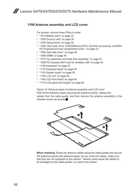
Figure 19. Removal steps of antenna assembly and LCD cover<br />
Peel off the adhesive tapes securing the antenna boards, release the<br />
cables from the cable guide, and then remove the antenna assembly in the<br />
direction shown by arrows 1.<br />
When installing: Route the antenna cables along the cable guides and secure<br />
the antenna boards with adhesive tapes. As you route the cables, make sure<br />
that they are not subjected to any tension. Tension could cause the cables to<br />
be damaged by the cable guides, or a wire to be broken.