Centrifugal Pumps Systems Characteristics - Peerless Pump
Centrifugal Pumps Systems Characteristics - Peerless Pump
Centrifugal Pumps Systems Characteristics - Peerless Pump

You also want an ePaper? Increase the reach of your titles
YUMPU automatically turns print PDFs into web optimized ePapers that Google loves.
Opening<br />
Slide
<strong>Centrifugal</strong> <strong><strong>Pump</strong>s</strong><br />
<strong>Systems</strong> <strong>Characteristics</strong>
Communication<br />
• Production<br />
• Engineering<br />
• Maintenance<br />
• Supplier
20 Year Life Cycle Costs<br />
+/-5% --Equipment Costs<br />
+/-15%-Installation<br />
+/-40%-Operation HP<br />
+/-40%-Parts & Labor
Matching the <strong>Pump</strong><br />
To the System Benefits<br />
• Energy savings- $400-1000/hp/yr<br />
• Extended <strong>Pump</strong> Life due to Reduced<br />
• Internal Wear<br />
• Minimal Radial Loads<br />
• Longer Valve Life<br />
• Stable Hydraulic Output
MTBF<br />
<strong>Centrifugal</strong> <strong><strong>Pump</strong>s</strong><br />
• Phase I- 6-8 months on average<br />
• Phase II- 12-16 months on average<br />
• Phase III- 2+ years
4 3<br />
Loose on Mountings<br />
Realign Belts<br />
Millwide Vibrations Problems<br />
# Workorders<br />
by Type<br />
45<br />
40<br />
35<br />
30<br />
25<br />
20<br />
15<br />
10<br />
5<br />
0<br />
41 38<br />
20<br />
12 11 11 10<br />
Alignment<br />
Bad Bearings<br />
Soft Feet<br />
Weak Base<br />
Clean Fan<br />
Balance Fan
External Considerations<br />
External Conditions<br />
Hydraulic<br />
Operating<br />
Conditions<br />
Installation<br />
Practices<br />
Drive Train<br />
Flow Rate<br />
Piping<br />
Base<br />
Coupling<br />
Driver<br />
Pressure<br />
Configuration<br />
Size and<br />
Style<br />
Size and<br />
Style<br />
Size<br />
Turbulent<br />
Flow<br />
Alignment<br />
Grouting<br />
Alignment<br />
Speed<br />
Support
Maintenance Cost Comparisons<br />
Maintenance<br />
Cost<br />
$/HP/Yr<br />
$18.0<br />
$16.0<br />
$14.0<br />
$12.0<br />
$10.0<br />
$8.0<br />
$6.0<br />
$4.0<br />
$2.0<br />
$0.0<br />
$17.5<br />
Run to<br />
Failure<br />
$12<br />
$8<br />
$4.5<br />
Preventive Predictive Precision
System Head Curve<br />
Total System Head<br />
• Static<br />
• Friction<br />
• Velocity<br />
• Pressure
Hydraulic Match<br />
Fit of <strong>Pump</strong> to System<br />
• To have a successful installation we must properly<br />
match the pump(s) to a system.<br />
• Therefore we must be able to create a system head<br />
curve on which we can plot the pump performance<br />
curve, showing, single, parallel and if applicable<br />
series pump operation<br />
• It is the intersection of the pump & system curve that<br />
determines where the pump actually operates on it’s<br />
performance curve
System Head Curves<br />
Critical Concerns<br />
• What will happen if the pump wears so head is down<br />
5%?<br />
• What will be the effect of a change in pressure in the<br />
tank into which the pump is pumping?<br />
• What will happen if deposits form in the piping?<br />
• What will happen at Max/Min levels in the suction<br />
tank?
System Head Curve<br />
Definition<br />
• By definition, the system head curve shows<br />
the head required by the system at various<br />
flow rates<br />
• The pump operates where its curve intersects<br />
the system head curve
System Head Curve<br />
Components<br />
• Static or pressure head (pumping up a hill,<br />
pumping into a boiler, etc) .<br />
• This head does not change with flow.<br />
• Friction Head. This head increases with the<br />
square of the flow. This head increases with<br />
the fifth power of the pipe diameter.
System/<strong>Pump</strong> Consideration<br />
Consider the Effect of:<br />
• Change in pump curve<br />
• Change in static or pressure head<br />
• Change in friction head<br />
Note: That the greater the angle of intersection<br />
between the pump and system head curve, the less<br />
the effect of a change in either curve.
System Head Variables (1)<br />
• Static Head will vary as a result of change in<br />
elevation of highest point of discharge of the<br />
system
System Head Variables (2)<br />
Friction Head at any specified flow will<br />
vary as a result of:<br />
• Change in viscosity resulting from a change in liquid<br />
temperature<br />
• Deterioration of the piping system<br />
• System differences between design and “as-built”<br />
• Accumulation of solids in the system<br />
• Load distribution<br />
• Friction losses tabulation procedures
Parallel <strong>Pump</strong> Operation<br />
Flow Additive<br />
• Draw a combined pump curve - add flows at constant head<br />
Factors in Parallel Operation<br />
• Shutoff Head<br />
• Curve Shape<br />
• Relative Sizes<br />
Advantages of Parallel Operation<br />
• Flexibility<br />
• Installed Cost<br />
• Operating Cost
Series <strong>Pump</strong> Operation<br />
Pressure Additive<br />
• Draw a combined pump curve- add the<br />
pressures(head) at constant flow<br />
Factors in Series Operation<br />
• Pressure Rating of the <strong>Pump</strong> Casing<br />
• Pressure Rating of the Piping & Components<br />
• Curve Shape<br />
Advantages of Series Operation<br />
• Installation/Equipment Cost<br />
• Flexibility in Design<br />
• Operating Cost
System Head Curves<br />
Classification of <strong>Systems</strong><br />
• Nonreturn <strong>Systems</strong>-<br />
Where all the liquid is discharged from the<br />
system<br />
• Return <strong>Systems</strong>-<br />
Where none of the liquid is discharged from<br />
the system<br />
Where some of the liquid is discharged from<br />
the system
System Classifications<br />
Thermal Exchange Applications (1)<br />
Thermal exchange, where some form of<br />
thermal exchange is conducted for the<br />
purpose of satisfying a design condition
System Classifications<br />
Thermal Exchange Applications (2)<br />
Chilled Water<br />
Cold Well<br />
Condenser Water<br />
Cooling Tower<br />
Heat Recovery<br />
Hot Well<br />
Mill Roll Cooling<br />
Plant Circulating Water<br />
Plant Cooling Water<br />
Spray Pond<br />
Strip Mill Quench
Removal/Delivery Applications (1)<br />
Removal/Delivery, where the system is<br />
designed to remove the liquid from or deliver<br />
it to some point to satisfy a specific design<br />
service
Removal/Delivery Applications<br />
(2)<br />
Ash Sluice<br />
Boiler Feed<br />
Condensate<br />
Domestic Water<br />
Effluent<br />
Filter Backwash<br />
Flood Irrigation<br />
High Service<br />
Low Service<br />
Municipal Booster<br />
Raw Water<br />
River Intake<br />
Sewage Ejector<br />
Sprinkler Irrigation<br />
Storm Water<br />
Charge
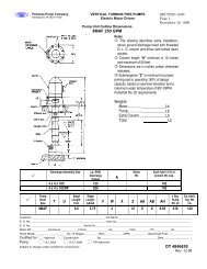
<strong>Pump</strong> Characteristic Performance Curve<br />
• Normally a constant speed plot<br />
• Axes- Flow (gpm), Head (feet)<br />
• Plot of efficiency, head capacity at constant diameter, BHP<br />
at 1.0 S.G., NPSHR<br />
• Note effects of specific gravity on head, pressure, BHP,<br />
suction pressure, viscosity on performance<br />
• Note the various head-capacity curve shapes based on<br />
different pump types:<br />
Axial Flow<br />
Mixed Flow<br />
Radial Flow
Oversized <strong>Pump</strong><br />
Retrofit Savings<br />
• Design is 1000 gpm at 315 ft tdh actual BHP is<br />
$48,000<br />
• Valved back to 650 gpm and operating at 420 ft tdh,<br />
actual BHP is $40,000<br />
• Resize pump for rating of 650 gpm at 230 ft tdh,<br />
actual BHP is $22,300<br />
• The actual cost of resizing pump is $4,560<br />
• The BHP $ savings of $40,000 – 22,300 = $17,700,<br />
or payback in 2.5 months!!!!!
<strong>Centrifugal</strong> <strong><strong>Pump</strong>s</strong><br />
Operating Zones (1)<br />
• Overcapcity Zone- The velocities within the pump<br />
are usually very high and recirculation occurs<br />
causing excessive wear in the presence of solids.<br />
The radial hydraulic loads on the impeller increase<br />
exponentially within a single volute casing<br />
• Recommended Operation Zone-The velocities<br />
within the pump are reduced. Recirculation is<br />
minimal and the flow in the suction nozzle should be<br />
axial( not induced vortex). The radial hydraulic loads<br />
are minimized.
<strong>Centrifugal</strong> <strong><strong>Pump</strong>s</strong><br />
Operating Zones (2)<br />
• Reduced Capacity Zone- The velocities within the pump are low,<br />
separation and recirculation occurs causing excessive wear in the<br />
presence of solids. Reducing the capacity should be limited because a<br />
certain minimum velocity must be maintained to avoid settling out of the<br />
solids; with the consequence of increased wear and clogging. The<br />
hydraulic radial loads will increase exponentially and the pump efficiency<br />
will decrease.<br />
• Shut Valve Zone- This is the point of zero flow, and pump should not be<br />
operated at this point for any length of time. Wear and tear will be rapid<br />
dud to separation and recirculation, the hydraulic forces will be at their<br />
highest, and settlement and plugging will occur. The pump will rapidly<br />
heat up, which is particularly serious in pumps, especially those of nonmetallic<br />
construction.
<strong>Centrifugal</strong> <strong><strong>Pump</strong>s</strong><br />
General Guidelines<br />
Selection & Application<br />
Types of <strong><strong>Pump</strong>s</strong>- Kinetic-<br />
<strong>Centrifugal</strong><br />
Materials of Construction-<br />
Temperatures & Concentrations<br />
Corrosion & Erosion<br />
Galling<br />
Minimum & Maximum Hydraulic<br />
Conditions<br />
Non-Overloading Motor<br />
Suction Conditions-Cavitation &<br />
Minimum Submergence<br />
Entrained Air<br />
Solids Handling<br />
Vibration Requirements<br />
Bearing B-10 life<br />
Shaft deflection Requirements<br />
Sealling Requirements<br />
Maintenance Requirements<br />
MTBF Requirements
<strong>Peerless</strong> <strong>Pump</strong> Company<br />
2005 Dr. M.L. King Jr. Street, P.O. Box 7026,<br />
Indianapolis, IN 46207-7026, USA<br />
Telephone: (317) 924-7378 Fax: (317) 924-7202<br />
www.peerlesspump.com<br />
LaBour <strong>Pump</strong> Company<br />
901 Ravenwood Drive, Selma, Alabama 36701<br />
Ph: (317) 924-7384 - Fax: (317) 920-6605<br />
www.labourtaber.com<br />
A Product of <strong>Peerless</strong> <strong>Pump</strong> Company<br />
Copyright © 2005 <strong>Peerless</strong> <strong>Pump</strong> Company