8MAF 250 GPM Weights - Peerless Pump
8MAF 250 GPM Weights - Peerless Pump
8MAF 250 GPM Weights - Peerless Pump

You also want an ePaper? Increase the reach of your titles
YUMPU automatically turns print PDFs into web optimized ePapers that Google loves.
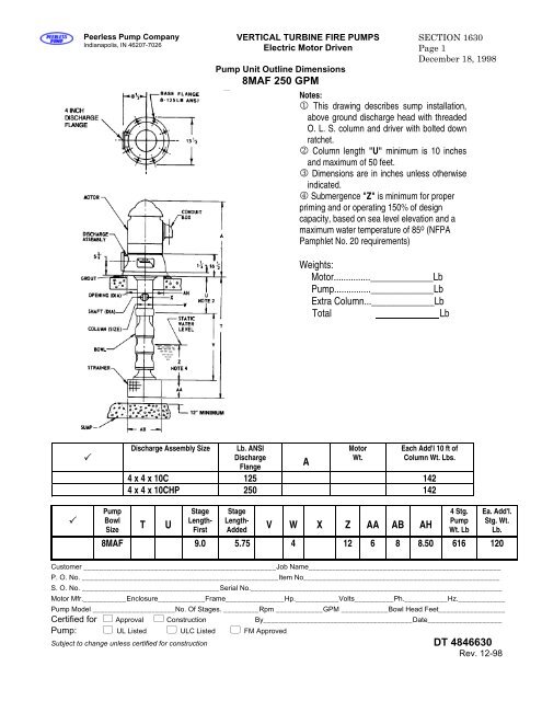
<strong>Peerless</strong> <strong>Pump</strong> CompanyIndianapolis, IN 46207-7026VERTICAL TURBINE FIRE PUMPSElectric Motor Driven<strong>Pump</strong> Unit Outline Dimensions<strong>8MAF</strong> <strong>250</strong> <strong>GPM</strong>SECTION 1630Page 1December 18, 1998Notes:1 This drawing describes sump installation,above ground discharge head with threadedO. L. S. column and driver with bolted downratchet.2 Column length "U" minimum is 10 inchesand maximum of 50 feet.3 Dimensions are in inches unless otherwiseindicated.4 Submergence "Z" is minimum for properpriming and or operating 150% of designcapacity, based on sea level elevation and amaximum water temperature of 85 o (NFPAPamphlet No. 20 requirements)<strong>Weights</strong>:Motor..............._____________Lb<strong>Pump</strong>..............._____________LbExtra Column..._____________LbTotalLbDischarge Assembly SizeLb. ANSIDischargeFlangeAMotorWt.Each Add'l 10 ft ofColumn Wt. Lbs.4 x 4 x 10C 125 1424 x 4 x 10CHP <strong>250</strong> 142<strong>Pump</strong>BowlSizeT UStageLength-FirstStageLength-AddedV W X Z AA AB AH4 Stg.<strong>Pump</strong>Wt. LbEa. Add'l.Stg. Wt.Lb.<strong>8MAF</strong> 9.0 5.75 4 12 6 8 8.50 616 120Customer _________________________________________________Job Name_________________________________________________P. O. No. __________________________________________________Item No__________________________________________________S. O. No. ___________________________________Serial No.________________________________________________________________Motor Mfr.___________Enclosure____________Frame_______________Hp.___________Volts__________Ph.___________Hz.____________<strong>Pump</strong> Model _____________________No. Of Stages. _________Rpm ____________<strong>GPM</strong> ____________Bowl Head Feet_________________Certified for Approval Construction By______________________________________Date___________________<strong>Pump</strong>: UL Listed ULC Listed FM ApprovedSubject to change unless certified for construction DT 4846630Rev. 12-98
SECTION 1630Page 2October 15, 2002VERTICAL TURBINE FIRE PUMPSElectric Motor Driven<strong>Peerless</strong> <strong>Pump</strong> CompanyIndianapolis, IN 46207-7026Note 1: This drawing describes a Vertical Turbine Fire <strong>Pump</strong>with Above Ground Discharge Head Casting, Threaded OpenLine Shaft Column, Motor having bolted down ratchet.Note 2: Column length U dimension is 10 Inches minimumand 50 feet maximum.Note 3: All dimensions are in inches unless otherwise noted.Note 4: Submergence Z is minimum for proper priming and/oroperation at 150% of design capacity, based on sea levelelevation and a maximum water temperature of 85 o F. perNFPA Pamphlet No. 20.<strong>Weights</strong>:Basic Two Stage <strong>Pump</strong>Electric MotorAdditional StagesAdditional ColumnFeetTotalDischargeAssembly SizeA B C E H (125 Lb Flg.)(-S Head)H (<strong>250</strong> Lb Flg.)(-SHP Head)J K N P Each Additional 10Feet of ColumnWeight Lb.2435270035504550455059736 x 6 x 12 13.69 0.75 6.50 8.00 NA 6 0.75 13.25 16 x 8 x 16-1/2 14.75 1.25 7.75 10.25 10.88 6 1.00 18.00 28 x 8 x 16-1/2 14.75 1.25 7.75 10.25 10.88 8 1.00 18.00 210 x 10 x 16-1/2 18.00 1.50 9.00 10.25 11.12 10 1.00 18.00 210 x 10 x 20 18.00 1.50 9.00 10.25 11.12 10 1.00 18.00 212 x 12 x 20 21.00 1.75 10.50 12.25 13.12 12 1.00 21.00 2<strong>Pump</strong>BowlSizeT U StageLength-FirstStageLength-AddedV W X Z AA AB AH 2 Stg.<strong>Pump</strong>Wt. Lb.Ea. Add’l.Stg. Wt. Lb.10MAF 16.81 7.50 6 10 8.63 10.25 12 919 7512MBF 19.50 9.50 8 19 10.00 12.00 14 1114 10614MCF 25.25 12.62 10 25 12.00 14.00 15 1531 16014MDF 31.25 13.25 10 25 15.38 15.50 17 1555 20016MCF 27.88 14.50 10 25 12.00 16.00 17 1824 27516HXBF 25.75 12.12 12 25 12.00 16.00 17 2210 27518HXBF 21.75 13.25 12 24 14.00 18.00 19 2655 500CustomerJob NameP. O. No. Item No.Invoice No.Serial NoMotor Mfr. Enclosure Frame Hp Volts Ph. Hz.<strong>Pump</strong> Model No. Of Stages Rpm <strong>GPM</strong> Bowl Head FeetCertified for By Date<strong>Pump</strong> UL Listed ULC Listed FM Approved DT 4853134Subject to change unless certified for construction by factory Rev. 08-02
<strong>Peerless</strong> <strong>Pump</strong> CompanyIndianapolis, IN 46207-7026VERTICAL TURBINE FIRE PUMPSTypes MAF, LDF, MBF, MCF, MDF, HXBFSECTION 1630Page 2.1October 15, 2002Note 1: This drawing describes a Vertical Turbine Fire <strong>Pump</strong>with Above Ground Discharge Head Casting, Treaded OpenLine Shaft Column, Right angle gear having bolted downratchet.Note 2: Column length U dimension is 10 Inches minimumand 50 feet maximum.Note 3: All dimensions are in inches unless otherwise noted.Note 4: Submergence Z is minimum for proper primingand/or operation at 150% of design capacity, based on sealevel elevation and a maximum water temperature of 85 o F.per NFPA Pamphlet No. 20.Note 5: Length R may be adjusted plus or minus 3/8 inch.Note 6: Tapped hole AD is to be connected by the customerto opening marked Raw Water Inlet on the engine outlinedrawing.<strong>Weights</strong>:Basic Two Stage <strong>Pump</strong>Right Angle GearAdditional StagesAdditional ColumnFeetTotalDischargeAssembly SizeA B C E H (125 LbFlg)(-S Head)H (<strong>250</strong> LbFlg)(-SHPHead)J K N P Q R S ADNPTEach Additional 10Feet of ColumnWeight Lb.6 x 6 x 12 13.69 0.75 6.50 8.00 NA 6 0.75 13.25 15 3/4 2436 x 8 x 16-1/2 14.75 1.25 7.75 10.25 10.88 6 1.00 18.00 20 3/4 2708 x 8 x 16-1/2 14.75 1.25 7.75 10.25 10.88 8 1.00 18.00 20 3/4 35510 x 10 x 16-1/2 18.00 1.50 9.00 10.25 11.12 10 1.00 18.00 20 3/4 45510 x 10 x 20 18.00 1.50 9.00 10.25 11.12 10 1.00 18.00 20 3/4 45512 x 12 x 20 21.00 1.75 10.50 12.25 13.12 12 1.00 21.00 23 1 597<strong>Pump</strong>BowlSizeT U StageLength-FirstStageLength-AddedV W X Z AA AB AH 2 Stage.<strong>Pump</strong>Wt. Lb.Ea. Add’l. Stage.Wt. Lb.10MAF 16.81 7.50 6 10 8.63 10.25 12 919 7512MBF 19.50 9.50 8 19 10.00 12.00 14 1114 10614MCF 25.25 12.62 10 25 12.00 14.00 15 1531 16014MDF 31.25 13.25 10 25 15.38 15.50 17 1555 20016MCF 27.88 14.50 10 25 12.00 16.00 17 1824 27516HXBF 25.75 12.12 12 25 12.00 16.00 17 2210 27518HXBF 21.75 13.25 12 24 14.00 18.00 19 2655 500CustomerJob NameP. O. No. Item No.Invoice No.Serial NoGear Mfr. Size Ratio<strong>Pump</strong> Model No. Of Stages Rpm Gpm Bowl Head FeetCertified for Approval Construction By Date<strong>Pump</strong> UL Listed ULC Listed FM Approved Right Angle FM Approved DT 4853135Subject to change unless certified for construction by factory Rev. 08-02
SECTION 1630Page 2.2December 18, 1998VERTICAL TURBINE FIRE PUMPSElectric Motor Driven<strong>Peerless</strong> <strong>Pump</strong> CompanyIndianapolis, IN 46207-7026Note 1: This drawing describes aVertical Turbine Fire <strong>Pump</strong> with AboveGround Discharge Head Casting,Threaded Open Line Shaft Column,Motor having bolted down ratchet.Note 2: Column length U dimension is10 Inches minimum and 50 feetmaximum.Note 3: All dimensions are in inchesunless otherwise noted.Note 4: Submergence Z is minimum forproper priming and/or operation at 150%of design capacity, based on sea levelelevation and a maximum watertemperature of 85 o F. per NFPAPamphlet No. 20.<strong>Weights</strong>:Basic Two Stage <strong>Pump</strong>Electric MotorAdditional StagesAdditional ColumnFeetTotalDischargeAssemblySize8 x 8 x 16-1/2x <strong>250</strong> LbANSI8 x 8 x 16-1/2x 300 LbANSIMaximumWorkingPressureA B C E H N P K T U X VEachAdditional10 Feet ofColumnWeight Lb.400 14.75 1.25 7.75 10.88 18.00 20 1.00 375600 31.12 1.75 9.75 15.00 21.00 24 1.12 375No. of Stages 8 9 10 11 12 13 14Dimension “V” 100.25 111.75 123.25 134.75 146.25 157.75 169.25Weight <strong>Pump</strong> Less Driver 10’ OLS Column 1542 1648 1754 2131 2237 2343 2449CustomerJob NameP. O. No. Item No.Invoice No.Serial NoMotor Mfr. Enclosure Frame Hp Volts Ph. Hz.<strong>Pump</strong> Model No. Of Stages Rpm <strong>GPM</strong> Bowl Head FeetCertified for Approval Construction By Date<strong>Pump</strong> UL Listed ULC Listed FM Approved DT 4851126Subject to change unless certified for construction by factory Rev. 12-98
<strong>Peerless</strong> <strong>Pump</strong> CompanyIndianapolis, IN 46207-7026VERTICAL TURBINE FIRE PUMPSDiesel Engine DrivenType 12LDF with Right Angle Gear DriveDimensional OutlineSECTION 1630Page 2.3August 28, 2000Note 1: This drawing describes a VerticalTurbine Fire <strong>Pump</strong> with Above GroundDischarge Head Casting, Flanged Open LineShaft Column, Right Angle Hollow Shaft Gearhaving bolted down ratchet.Note 2: Column length U dimension is 10Inches minimum and 50 feet maximum.Note 3: All dimensions are in inches unlessotherwise noted.Note 4: Submergence is minimum for properpriming and/or operation at 150% of designcapacity, based on sea level elevation and amaximum water temperature of 85 o F. perNFPA Pamphlet No. 20.Note 5: Length R may be adjusted plus orminus 3/8 inch.Note 6: Tapped hole is to be connected bythe customer to opening marked Raw WaterInlet on the engine outline drawing.<strong>Weights</strong>:Basic 8 Stage <strong>Pump</strong>1542 Lb.Add for Each AdditionalStage Add 106 LbLb.Right Angle GearLb.Additional ColumnLb.Feet Lb Lb.TotalLb.<strong>Pump</strong>ModelDischargeHead Size &DischargeFlange ANSIRating Lb8 x 8 x 16.5DischargeHeadMaximumWorkingPressurePSIA B C E H N P K Q R S T U V X AD AE12LDF <strong>250</strong> 400 14.75 1.25 7.75 10.88 18 20 1.00 3/4 -12LDF 300 600 31.12 1.75 9.75 15.00 21 24 1.12 - 1No of Stages 8 9 10 11 12 13 14Dimension V 100.25 111.75 123.25 134.75 146.25 157.75 169.25CustomerJob NameP. O. No. Item No.Invoice No.Serial NoGear Mfr. Size Ratio<strong>Pump</strong> Model No. Of Stages Rpm 1760 <strong>GPM</strong> Bowl Head FeetCertified for Approval Construction By Date<strong>Pump</strong> UL Listed ULC Listed FM Approved Right Angle Gear FM Approved DT 4851127Subject to change unless certified for construction by factory Rev. 8-00
SECTION 1630Page 2.4August 28, 2000VERTICAL TURBINE FIRE PUMPSElectric Motor DrivenType 20HXBFDimensional Outline<strong>Peerless</strong> <strong>Pump</strong> CompanyIndianapolis, IN 46207-7026Note 1: This drawing describes a VerticalTurbine Fire <strong>Pump</strong> with Above GroundDischarge Head Casting , Flanged Open LineShaft Column, Electric Vertical Hollow ShaftMotor having bolted down ratchet.Note 2: Column length U dimension is 10Inches minimum and 50 feet maximum.Note 3: All dimensions are in inches unlessotherwise noted.Note 4: Submergence is minimum for properpriming and/or operation at 150% of designcapacity, based on sea level elevation and amaximum water temperature of 85 o F. perNFPA Pamphlet No. 20.<strong>Weights</strong>:Basic Two Stage <strong>Pump</strong>Electric VHS MotorAdditional ColumnFeetTotal3570 Lb.Lb.Lb.Lb.Lb.<strong>Pump</strong>ModelDischargeFlangeANSIRating LbDischarge HeadMaximumWorkingPressure PSIVariable DimensionsDischarge Flange HolesA T U CF N BC H20HXBF 125 150 14.75 12 18.75 1-8 UNC20HXBF <strong>250</strong> <strong>250</strong> 15.62 20 20.25 1-1/8-7 UNCCustomerJob NameP. O. No. Item No.Invoice No.Serial NoMotor Mfg. Hp Volts Ph Hz Frame<strong>Pump</strong> Model No. Of Stages 2 Rpm 1760 <strong>GPM</strong> Bowl Head FeetCertified for Approval Construction By Date<strong>Pump</strong> UL Listed ULC Listed FM Approved Electric Motor UL Listed DT 4849200Subject to change unless certified for construction by factory Rev. 8-00
<strong>Peerless</strong> <strong>Pump</strong> CompanyIndianapolis, IN 46207-7026VERTICAL TURBINE FIRE PUMPSDiesel Engine DrivenType 20HXBF with Right Angle Gear DriveDimensional OutlineSECTION 1630Page 3August 28, 2000Note 1: This drawing describes a VerticalTurbine Fire <strong>Pump</strong> with Above GroundDischarge Head Casting, Flanged Open LineShaft Column, Right Angle Hollow Shaft Gearhaving bolted down ratchet.Note 2: Column length U dimension is 10Inches minimum and 50 feet maximum.Note 3: All dimensions are in inches unlessotherwise noted.Note 4: Submergence is minimum for properpriming and/or operation at 150% of designcapacity, based on sea level elevation and amaximum water temperature of 85 o F. perNFPA Pamphlet No. 20.Note 5: Length R may be adjusted plus orminus 3/8 inch.Note 6: Tapped hole is to be connected by thecustomer to opening marked Raw Water Inleton the engine outline drawing.<strong>Weights</strong>:Basic Two Stage <strong>Pump</strong> 3570 Lb.Right Angle GearLb.Additional ColumnLb.FeetLb.TotalLb.<strong>Pump</strong>ModelDischargeFlangeANSI RatingLbDischargeHeadMaximumVariable DimensionsDischarge Flange HolesWorkingPressure PSI A Q R S T U CF N BC H20HXBF 125 150 14.75 12 18.75 1-8 UNC20HXBF <strong>250</strong> <strong>250</strong> 15.62 20 20.25 1-1/8-7 UNCCustomerJob NameP. O. No. Item No.Invoice No.Serial NoGear Mfr. Size Ratio<strong>Pump</strong> Model No. Of Stages 2 Rpm 1760 <strong>GPM</strong> Bowl Head FeetCertified for Approval Construction By Date<strong>Pump</strong> UL Listed ULC Listed FM Approved Right Angle Gear FM Approved DT 4849199Subject to change unless certified for construction by factory Rev. 8-00
<strong>Peerless</strong> <strong>Pump</strong> CompanyIndianapolis, IN 46207-7026VERTICAL TURBINE FIRE PUMPSDiesel Engine DrivenCLARKE ENGINE OUTLINE(LAYOUT DIMENSIONS)SECTION 1630Page 4.1March 27, 1998ENGINE MANUFACTURER ENGINE MODELS MAXIMUM DIMENSIONS (in Inches)A B C D E F GCLARKE VMFP04HN, HT 57 31 53 12 62 32 74CLARKEVMFP06HT, T6HT, L6HT,L6HR,T6HR66 30 53 12 62 32 74Most controllers may be floor or base mounted.Base mounted controller, as shown with pump and engine is optional.All dimensions are approximate and may be used for general layout purposes only.Certified dimensional outline drawings will be submitted on job when entered at the factory for approval orconstruction.Subject to change without notice
Blank
SECTION 1630Page 6March 27 1998VERTICAL TURBINE FIRE PUMPSDiesel Engine DrivenType 12LDF with Suction Vessel MountingArrangement at Discharge Head AssemblyDimensional Outline<strong>Peerless</strong> <strong>Pump</strong> CompanyIndianapolis, IN 46207-7026Note 1: This drawing describes a Vertical Turbine Fire <strong>Pump</strong> with Suction Vessel Installation Discharge HeadAssembly, Flanged Open Line Shaft Column, Vertical Hollow Shaft Electric Motor having bolted down ratchet.Note 2: Maximum suction pressure is 100 PSINote 3: All dimensions are in inches unless otherwise noted.Note 4: <strong>Weights</strong> are for basic 3 stage pump unit and suction vessel less driver and weight of water (1.0 SG)contained in vesselNote 5: Installer to allow for grout between top of foundation and bottom of base. Grout thickness is to bedetermined by installing contractor.<strong>Weights</strong>:Basic 3 Stage <strong>Pump</strong> 1720 Lb. 782 Kgeach additional stage @247 Lb (112 Kg) per stageincluding weight of water stages Lb. KgVertical Hollow Shaft Motor Lb. KgTotal Lb. KgDischarge Head SizeDischarge FlangeANSI Rating Lb.Discharge HeadMaximumWorkingPressure PSIAWt HeadLb6x8x16.5T 150 235 6506x8x16.5T 300 600 6506x8x16.5T 400 825 6506x8x16.5T 600 1000 650No of Stages 3 4 5 6 7 8 9 10 11 12 13 14Dimension L 66 77.5 89 100.5 112 123.5 135 146.5 158 169.5 181 192.5Dimension X 1.5 1.5 1.5 1.5 1.5 1.5 1.5 1.5 1.69 1.69 1.69 1.69CustomerJob NameP. O. No. Item No.Invoice No.Serial NoMotor Mfr. Frame HP Volts Phase Hz<strong>Pump</strong> Model 12LDF No. Of Stages Rpm 1760 <strong>GPM</strong> Bowl Head FeetCertified for Approval Construction By Date<strong>Pump</strong> UL Listed Page 1 of 2DT 4852432Subject to change unless certified for construction by factory Rev. 3-98
<strong>Peerless</strong> <strong>Pump</strong> CompanyIndianapolis, IN 46207-7026VERTICAL TURBINE FIRE PUMPSElectric Motor DrivenMotor Drive Outline12LDFwith Suction VesselMounting Arrangement at Discharge HeadSECTION 1630Page 7June 22, 1990
SECTION 1630Page 8June 22, 1990VERTICAL TURBINE FIRE PUMPSElectric Motor DrivenMotor Drive Outline12LDF with Suction VesselMounting Arrangement at Discharge Head Assembly<strong>Peerless</strong> <strong>Pump</strong> CompanyIndianapolis, IN 46207-7026
<strong>Peerless</strong> <strong>Pump</strong> CompanyIndianapolis, IN 46207-7026VERTICAL TURBINE FIRE PUMPSElectric Motor DrivenMotor Drive Outline12LDFwith Suction VesselMounting Arrangement at Discharge HeadSECTION 1630Page 9June 22, 1990
SECTION 1630Page 10June 22, 1990VERTICAL TURBINE FIRE PUMPSElectric Motor DrivenMotor Drive Outline12LDF with Suction VesselMounting Arrangement at Discharge Head Assembly<strong>Peerless</strong> <strong>Pump</strong> CompanyIndianapolis, IN 46207-7026
<strong>Peerless</strong> <strong>Pump</strong> CompanyIndianapolis, IN 46207-7026VERTICAL TURBINE FIRE PUMPSElectric Motor DrivenMotor Drive Outline12LDFwith Suction Vessel (3- 10 Stages)Mounting Arrangement at Discharge HeadSECTION 1630Page 11June 22, 1990
SECTION 1630Page 12June 22, 1990VERTICAL TURBINE FIRE PUMPSElectric Motor DrivenMotor Drive Outline12LDF with Suction Vessel (11-14 Stages)Mounting Arrangement at Discharge Head Assembly<strong>Peerless</strong> <strong>Pump</strong> CompanyIndianapolis, IN 46207-7026
<strong>Peerless</strong> <strong>Pump</strong> CompanyIndianapolis, IN 46207-7026VERTICAL TURBINE FIRE PUMPSElectric Motor DrivenMotor Drive Outline12LDFwith Suction Vessel (11-14 Stages)Mounting Arrangement at Discharge HeadSECTION 1630Page 13June 22, 1990
SECTION 1630Page 14June 22, 1990VERTICAL TURBINE FIRE PUMPSElectric Motor DrivenMotor Drive Outline12LDF with Suction VesselMounting Arrangement at Discharge Head Assembly<strong>Peerless</strong> <strong>Pump</strong> CompanyIndianapolis, IN 46207-7026
<strong>Peerless</strong> <strong>Pump</strong> CompanyIndianapolis, IN 46207-7026VERTICAL TURBINE FIRE PUMPSType12LDFwith Suction Vessel Mounting Arrangement atDischarge Head Assembly and Right Angle GearDriveSECTION 1630Page 15March 27, 1998Page 2 of 24852519
SECTION 1630Page 16March 27, 1998VERTICAL TURBINE FIRE PUMPSElectric Motor or Diesel Engine Driven<strong>Peerless</strong> <strong>Pump</strong> CompanyIndianapolis, IN 46207-7026RIGHT ANGLE GEAR DIMENSIONS IN INCHESAMARILLO JOHNSON DE'RANMODEL AG BD D XA MODEL AG BD D XA MODEL AG BD D XASL30 16.25 10.00 6.75 10.88 H40(12) 24.75 12.00 9.00 16.00 G40-FM 26.62 16.50 11.43 18.00SL40A 21.75 12.00 8.50 15.62 H40 24.75 16.50 9.00 16.00 G60-FM 26.62 16.50 11.43 18.00SL40B 21.75 16.50 8.50 15.62 H60 24.75 16.50 9.00 16.00 G80-FM 26.62 16.50 11.43 18.00SL60A, 28.00 16.50 11.50 16.75 H80, H80HT 24.75 16.50 9.00 16.50 G100A-FM 26.62 16.50 11.43 17.93SHC60ASL80A, 29.25 16.50 11.50 16.75 H110, 29.50 16.50 11.38 17.50 G125A-FM 26.62 16.50 11.43 17.93SHC80AH110HTSL100A, 29.25 16.50 11.50 16.75 H125, 29.50 16.50 11.38 17.50 G150A-FM 33.88 20.00 13.75 20.87SHC100AH125HTSL125A, 29.25 16.50 11.50 16.75 H150, 34.50 20.00 13.25 20.50 G200B-FM 33.88 20.00 13.75 20.87SHC125AH150HTSL150A, 29.37 16.50 11.50 18.75 H200, 34.50 20.00 13.25 20.50 G<strong>250</strong>A-FM 33.88 20.00 13.75 21.75SHC150AH200HTSL200A, 34.68 20.00 13.75 20.75 HG<strong>250</strong>, 46.00 24.50 16.50 29.00 G300A-FM 35.62 20.00 13.75 21.75SHC200AHG<strong>250</strong>HTS<strong>250</strong> 34.68 20.00 13.75 22.38 HH350 46.00 24.50 16.50 30.00 G350A-FM 35.62 20.00 13.75 21.75S300 34.68 20.00 13.75 22.38 HH350HT 46.00 24.50 16.50 30.00 G400A-FM 35.62 20.00 13.75 21.75S350 34.68 20.00 13.75 22.38 HH425 46.00 24.50 16.50 31.00 G450A-FM 65.62 20.00 13.75 21.75SL450A, 43.25 24.50 16.00 25.50 HH425HT 46.00 24.50 16.50 31.00 F500A-FM 45.12 24.50 18.75 28.00SC450ASL500A, 43.25 24.50 16.00 25.50 HI500 51.00 24.50 16.50 33.00 F590A-FM 45.12 24.50 18.75 28.00SC500ASL600A, 43.25 24.50 16.00 25.50 HI500HT 51.00 24.50 16.50 33.00 F750A-FM 45.12 24.50 18.75 28.00SC600A 1:1 Ratio only, refer to the factory for other ratios.Universal Joint Drive Shaft Dimensions in InchesSHAFT SIZE SC1310 SC1350 SC1410 SC1480 SC1550 SC1610 SC1710 SC1810 SC1880R (LENGTH) 9.50 9.87 9.87 9.00 10.25 11.25 13.00 15.53 16.12LENGTHEN OR SHORTEN 0.62 0.37 0.37 0.50 0.50 0.37 0.37 0.56 0.50J (MINIMUM ANGLE) 1/2° 1/2° 1/2° 1/2° 1/2° 1/2° 1/2° 1/2° 1/2°J (MAXIMUM ANGLE) 3° 3° 3° 3° 3° 3° 3° 3° 3°APPROX. WT. LBS. 34 34 34 40 59 73 102 116 186REV. 3-98Dimensions are subject to change without notice DT 4852694
<strong>Peerless</strong> <strong>Pump</strong> CompanyIndianapolis, IN 46207-7026Vertical Turbine Fire <strong>Pump</strong>sElectric Motor or Diesel Engine DrivenFire <strong>Pump</strong> Fittings OutlineSECTION 1630Page 21March 27, 1998Notes:1. Only Items Marked will be furnished2. All Dimensions are in inches3. Hose Valve Threading _______________________-(Specify) Item No. <strong>GPM</strong> <strong>GPM</strong> <strong>GPM</strong> <strong>GPM</strong> <strong>GPM</strong> Description Maximum Working Pressure PSIG9A <strong>250</strong> - - - - - - - - Hose Valve Head 175 400 - - - -9B 500 750 1000 1<strong>250</strong> - - Hose Valve Head 175 200 400 6009B 1500 2000 <strong>250</strong>0 - - - - Hose Valve Head 175 200 400 6009C 3000 3500 4000 4500 5000 Hose Valve Head 150 175 300 6009D 500 - - - - - - - - Hose Valve Head 300 - - - - - -10 Angle Hose Valve Qty of Wt. Lbs. 300 - - - - - -12 Cap & Chain Qty of Wt. Lbs. - - - - - - -16 Drain Valve 400 600 - - - -Discharge Gauge Dial Graduations18 Gauge Set ( Type Outer Scale Inner ScaleFurnished with Gauge Discharge 0 PSI to 300 PSI 0 to 20 BARCock) Discharge 0 to 600 PSI 0 BAR to 41 BARANSI Std.Dimension FlangeDimen-sion <strong>250</strong><strong>Pump</strong> Rating <strong>GPM</strong>50 750 1000 1<strong>250</strong> 1500 2000 <strong>250</strong>0 3000 3500 4000 4500 50000125 W 3 6 8 8 10 10 10 12 - - - - -150 W 3 4 6 6 8 8 8 10 10 12 12 12 12150 W - - - - - - - - 12 14 14 14 14<strong>250</strong> W 3 6 8 8 10 10 10 12 - - - - -300 W 3 4 6 6 8 8 8 10 10 12 12 12 12300 W - - - - - - - - 12 14 14 14 14Quantity Q 1 2 3 4 6 6 6 8 12 12 16 16 20Weight Lbs. (Maximum) 25 50 84 84 150 150 150 255 360 360 360 360 360Item No. 9A 9B 9B 9B 9B 9B 9B 9B 9C 9C 9C 9C 9CDT4851091Subject to change without notice Rev 1-93
SECTION 1630Page 22March 13, 1998VERTICAL TURBINE FIRE PUMPSElectric Motor DrivenFire <strong>Pump</strong> Fitting Outline DimensionsStandard Pressure<strong>Peerless</strong> <strong>Pump</strong> CompanyIndianapolis, IN 46207-7026Notes:1. Only Items marked will be furnished.2. All dimensions are In Inches.3. <strong>Pump</strong> flanges must not be used to support weight of fittings.4A4. All fitting flanges will conform to ANSI Standard B16.1 and will be:a.} 125 Lb. on relief valve Inlet and relief valve elbow.b.} 150 Lb. on OCV, Cla-Val relief valve inlet and outlet.c.} 125 or 150 Lb. on tee.d.} 125 or 150 Lb. cone Inlet and outlet.5. All gaskets and bolting are to be supplied by others.6. All direct acting and pilot operated valves are suitable for a back pressure up to 100 psi. Item Description4 Discharge TeeRelief Valve Elbow5 Direct Acting Relief Valve6 Pilot Operated Relief Valve7 Overflow Cone15A Air Release Valve Assembly Manufacturer Model Listing /Approval Pressure Range Psi3 In 4 In 6 In 8 InKunkle 218CS164 UL/FM UL/FM UL/FM Not Available 70 to 170Watts 1116FM UL UL UL UL 20 to 175OCV OCV 108FCA UL UL UL UL 20 to 175Cla-Val 50BK4KG1 UL/FM UL/FM UL/FM UL/FM 20 to 200 Must be mounted with stem in vertical position, interchange elbow and relief valve.Rev 3-98Page 1 of 2DT4852885Subject to change without notice
<strong>Peerless</strong> <strong>Pump</strong> CompanyIndianapolis, IN 46206-7026VERTICAL TURBINE FIRE PUMPSDiesel Engine DrivenFire <strong>Pump</strong> Fitting Outline DimensionsStandard PressureSECTION 1630Page 23March 13, 1998Notes:1. Only Items marked will be furnished.2. All dimensions are In Inches. Item Description3. <strong>Pump</strong> flanges must not be used to support weight of fittings.4. All fitting flanges will conform to ANSI Standard B16.1 and4Awill be:a.} 125 Lb. on relief valve Inlet and relief valve elbow.b.} 150 Lb. on OCV, Cla-Val relief valve inlet and outlet.c.} 125 or 150 Lb. on tee.d.} 125 or 150 Lb. cone Inlet and outlet.5. All gaskets and bolting are to be supplied by others.6. All direct acting and pilot operated valves are suitable for a back pressure up to 100 psi.4 Discharge TeeRelief Valve Elbow5 Direct Acting Relief Valve6 Pilot Operated Relief Valve7 Overflow Cone15B Air Release Valve Assembly Manufacturer Model Listing /Approval Pressure Range Psi3 In 4 In 6 In 8 InKunkle 218CS164 UL/FM UL/FM UL/FM Not Available 70 to 170Watts 1116FM UL UL UL UL 20 to 175OCV OCV 108FCA UL UL UL UL 20 to 175Cla-Val 50BK4KG1 UL/FM UL/FM UL/FM UL/FM 20 to 200 Must be mounted with stem in vertical position extra fittings are required refer to factory Rev 3-98Page 1 of 2Subject to change without noticeDT4852886
SECTION 1630Page 24September 14, 2004VERTICAL TURBINE FIRE PUMPSElectric Motor or Diesel Engine DrivenFire <strong>Pump</strong> Fitting Outline DimensionsStandard Pressure<strong>Peerless</strong> <strong>Pump</strong> CompanyIndianapolis, IN 46207-7026DISCHARGE TEE ASSEMBLY WITH KUNKLE DIRECT ACTING RELIEF VALVEPUMP MAXIMUM TOTALRATED WORKING A B C E G H5 J K5 L R ASSEM<strong>GPM</strong> PRESSURE WTPSI lb500 170 6.0 3.0 5.0 8.0 5.5 6.12 12.38 5.88 8.5 1.5 279500 170 8.0 3.0 5.0 9.0 5.5 6.12 12.38 5.88 8.5 1.5 333750 170 6.0 4.0 8.0 8.0 6.5 6.62 17.00 6.44 10.5 1.5 444750 170 8.0 4.0 8.0 9.0 6.5 6.62 17.00 6.44 10.5 1.5 4441000 170 6.0 4.0 8.0 8.0 6.5 6.62 17.00 6.44 10.5 1.5 4441000 170 8.0 4.0 8.0 9.0 6.5 6.62 17.00 6.44 10.5 1.5 4441<strong>250</strong> 170 10.0 6.0 10.0 11.0 8.0 9.38 17.88 8.50 14.0 1.5 7141500 170 10.0 6.0 10.0 11.0 8.0 9.38 17.88 8.50 14.0 1.5 7142000 170 10.0 6.0 10.0 11.0 8.0 9.38 17.88 8.50 14.0 1.5 714<strong>250</strong>0 170 12.0 6.0 10.0 12.0 8.0 9.38 17.88 8.50 14.0 1.5 8143000ø 175 12.0 8.0 12.0 12.0 9.0 10.62 34.38 10.00 9.0 2.5 13253000* 150 14.0 8.0 12.0 14.0 9.0 10.62 34.38 10.00 9.0 2.5 13253500¤ 175 12.0 8.0 12.0 12.0 9.0 10.62 34.38 10.00 9.0 2.5 12074000 150 14.0 8.0 14.0 14.0 9.0 10.62 34.38 10.00 14.0 2.5 13254500 150 14.0 8.0 14.0 14.0 9.0 10.62 34.38 10.00 14.0 2.5 1325DISCHARGE TEE ASSEMBLY WITH PILOT OPERATED RELIEF VALVEPUMP MAXIMUM WATTS OCV CLA-VAL TOTALRATED WORKING A B C E G H6 J K6 H6 J K6 H6 J K6 L R ASSEM<strong>GPM</strong> PRESSURE WTPSI lb500 175 6.0 3.0 5.0 8.0 5.5 5.75 12.38 5.75 4.00 10.38 6.00 4.00 12.50 6.00 8.5 1.5 266500 175 8.0 3.0 5.0 9.0 5.5 5.75 12.38 5.75 4.00 10.38 6.00 4.00 12.50 6.00 8.5 1.5 320750 175 6.0 4.0 8.0 8.0 6.5 6.75 17.00 6.75 4.50 11.88 7.50 5.00 13.00 7.50 10.5 1.5 434750 175 8.0 4.0 8.0 9.0 6.5 6.75 17.00 6.75 4.50 11.88 7.50 5.00 13.00 7.50 10.5 1.5 4341000 175 6.0 4.0 8.0 8.0 6.5 6.75 17.00 6.75 4.50 11.88 7.50 5.00 13.00 7.50 10.5 1.5 4341000 175 8.0 4.0 8.0 9.0 6.5 6.75 17.00 6.75 4.50 11.88 7.50 5.00 13.00 7.50 10.5 1.5 4341<strong>250</strong> 175 10.0 6.0 10.0 11.0 8.0 8.50 17.88 8.50 6.00 13.88 10.00 6.00 14.31 10.00 14.0 1.5 7391500 175 10.0 6.0 10.0 11.0 8.0 8.50 17.88 8.50 6.00 13.88 10.00 6.00 14.31 10.00 14.0 1.5 7392000 175 10.0 6.0 10.0 11.0 8.0 8.50 17.88 8.50 6.00 13.88 10.00 6.00 14.31 10.00 14.0 1.5 739<strong>250</strong>0 175 12.0 6.0 10.0 12.0 8.0 8.50 17.88 8.50 6.00 13.88 10.00 60.00 14.31 10.00 14.0 1.5 8393000ø 175 12.0 8.0 12.0 12.0 9.0 11.00 34.38 11.00 8.00 18.25 12.69 8.00 16.31 12.75 9.0 2.5 12323000* 150 14.0 8.0 12.0 14.0 9.0 11.00 34.38 11.00 8.00 18.25 12.69 8.00 16.31 12.75 9.0 2.5 13503500¤ 175 12.0 8.0 12.0 12.0 9.0 11.00 34.38 11.00 8.00 18.25 12.69 8.00 16.31 12.75 9.0 2.5 12324000 150 14.0 8.0 14.0 14.0 9.0 11.00 34.38 11.00 8.00 18.25 12.69 8.00 16.31 12.75 14.0 2.5 13504500 150 14.0 8.0 14.0 14.0 9.0 11.00 34.38 11.00 8.00 18.25 12.69 8.00 16.31 12.75 14.0 2.5 1350ø APPLIES ONLY TO 16HXBF @ 3000 <strong>GPM</strong>* APPLIES ONLY TO 20HXBF @ 3000 <strong>GPM</strong>¤ APPLIES ONLY TO 18HXBF @ 3500 <strong>GPM</strong>Page 2 of 2DT 4852885DT 4852886Subject to change without notice Rev. 09-04
<strong>Peerless</strong> <strong>Pump</strong> CompanyIndianapolis, IN 46207-7026VERTICAL TURBINE FIRE PUMPSElectric Motor DrivenFire <strong>Pump</strong>s Fittings Outline DimensionsHigh PressureSECTION 1630Page 25March 13, 1998Notes:1. Only Items marked will be furnished.2. All dimensions are In Inches.3. <strong>Pump</strong> flanges must not be used to support weight of fittings.4A4. All fitting flanges will conform to ANSI Standard B16.1 and will be:a.} <strong>250</strong> Lb. on relief valve Inlet and relief valve elbow.b.} 300 Lb. on OCV, Cla-Val Valve inlet and outlet.c.} <strong>250</strong> or 300 Lb. on tee.d.} 125 or 150 Lb. cone Inlet and outlet.5. All gaskets and bolting are to be supplied by others.6. All direct acting and pilot operated valves are suitable for a back pressure up to 100 psi. Item Description4 Discharge TeeRelief Valve Elbow5 Direct Acting Relief Valve6 Pilot Operated Relief Valve7 Overflow Cone15A Air Release Valve Assembly Manufacturer Model Listing /Approval Pressure Range Psi3 In 4 In 6 In 8 InKunkle 218CS164 UL/FM UL/FM UL/FM Not Available 70 to 200Watts 1116FM UL UL UL Not Listed orApprovedOCV OCV 108FCA UL UL UL Not ULListed100 to 300100 to 300Cla-Val 50BK4KG1 UL UL UL Not UL Listed 100 to 300Cla-Val 50BK4KG1 FM FM FM FM 20 to 200 Must be mounted with stem in vertical position, refer to factory for required fittings to adapt.Rev 3-98Page 1 of 2DT4852887Subject to change without notice
SECTION 1630Page 26March 13, 1998VERTICAL TURBINE FIRE PUMPSDiesel Engine DrivenFire <strong>Pump</strong>s Fittings Outline DimensionsHigh Pressure<strong>Peerless</strong> <strong>Pump</strong> CompanyIndianapolis, IN 46207-7026Notes:1. Only Items marked will be furnished.2. All dimensions are In Inches.3. <strong>Pump</strong> flanges must not be used to support weight of fittings.4A4. All fitting flanges will conform to ANSI Standard B16.1 and will be:a.} <strong>250</strong> Lb. on relief valve Inlet and relief valve elbow.b.} 300 Lb. on OCV, Cla-Val Valve inlet and outlet.c.} <strong>250</strong> or 300 Lb. on tee.d.} 125 or 150 Lb. cone Inlet and outlet.5. All gaskets and bolting are to be supplied by others.6. All direct acting and pilot operated valves are suitable for a back pressure up to 100 psi. Item Description4 Discharge TeeRelief Valve Elbow5 Direct Acting Relief Valve6 Pilot Operated Relief Valve7 Overflow Cone15B Air Release Valve Assembly Manufacturer Model Listing /Approval Pressure Range Psi3 In 4 In 6 In 8 InKunkle 218CS164 UL/FM UL/FM UL/FM Not Available 70 to 200Watts 1116FM UL UL UL Not Listed orApproved100 to 300OCV OCV 108FCA UL UL UL Not UL Listed 100 to 300Cla-Val 50BK4KG1 UL UL UL Not UL Listed 100 to 300Cla-Val 50BK4KG1 FM FM FM FM 20 to 200 Must be mounted with stem in vertical position extra fittings are required refer to factoryRev 3-98Page 1 of 2DT4852888Subject to change without notice
<strong>Peerless</strong> <strong>Pump</strong> CompanyIndianapolis, IN 46207-7026VERTICAL TURBINE FIRE PUMPSElectric Motor or Diesel Engine DrivenFire <strong>Pump</strong> Fitting Outline DimensionsHigh PressureSECTION 1630Page 27September 14, 2004DISCHARGE TEE ASSEMBLY WITH KUNKLE DIRECT ACTING RELIEF VALVEPUMP MAXIMUM TOTALRATED WORKING A B C E G H5 J K5 L R ASSEM<strong>GPM</strong> PRESSURE WTPSI lb500 200 6.0 3.0 5.0 8.5 6.0 6.12 12.38 5.88 8.5 1.5 360500 200 8.0 3.0 5.0 10.0 6.0 6.12 12.38 5.88 8.5 1.5 422750 200 6.0 4.0 8.0 8.5 7.0 6.62 17.00 6.44 10.5 1.5 564750 200 8.0 4.0 8.0 10.0 7.0 6.62 17.00 6.44 10.5 1.5 5641000 200 6.0 4.0 8.0 8.5 7.0 6.62 17.00 6.44 10.5 1.5 5641000 200 8.0 4.0 8.0 10.0 7.0 6.62 17.00 6.44 10.5 1.5 5641<strong>250</strong> 200 10.0 6.0 10.0 11.5 8.5 9.38 17.88 8.50 14.0 1.5 9241500 200 10.0 6.0 10.0 11.5 8.5 9.38 17.88 8.50 14.0 1.5 9242000 200 10.0 6.0 10.0 11.5 8.5 9.38 17.88 8.50 14.0 1.5 924<strong>250</strong>0 200 12.0 6.0 10.0 13.0 8.5 9.38 17.88 8.50 14.0 1.5 1024DISCHARGE TEE ASSEMBLY WITH PILOT OPERATED RELIEF VALVEPUMP MAXIMUM Watts OCV CLA-VAL TOTALRATED WORKING A B C E G H6 J K6 H6 J K6 H6 J K6 L R ASSEM<strong>GPM</strong> PRESSURE WTPSI lb500 400 6.0 3.0 5.0 8.5 6.0 6.12 13.00 5.75 4.38 10.38 6.00 4.38 12.50 6.00 8.5 1.5 347500 400 8.0 3.0 5.0 10.0 6.0 6.12 13.00 5.75 4.38 10.38 6.00 4.38 12.50 6.00 8.5 1.5 409750 400 6.0 4.0 8.0 8.5 7.0 7.12 17.00 6.75 5.81 11.88 7.81 5.31 13.00 7.50 10.5 1.5 554750 400 8.0 4.0 8.0 10.0 7.0 7.12 17.00 6.75 5.81 11.88 7.81 5.31 13.00 7.50 10.5 1.5 5541000 400 6.0 4.0 8.0 8.5 7.0 7.12 17.00 6.75 5.81 11.88 7.81 5.31 13.00 7.50 10.5 1.5 5541000 400 8.0 4.0 8.0 10.0 7.0 7.12 17.00 6.75 5.81 11.88 7.81 5.31 13.00 7.50 10.5 1.5 5541<strong>250</strong> 300 10.0 6.0 10.0 11.5 8.5 9.00 18.00 8.50 6.50 13.88 10.00 6.50 14.31 10.00 14.0 1.5 9441500 300 10.0 6.0 10.0 11.5 8.5 9.00 18.00 8.50 6.50 13.88 10.00 6.50 14.31 10.00 14.0 1.5 9442000 300 10.0 6.0 10.0 11.5 8.5 9.00 18.00 8.50 6.50 13.88 10.00 6.50 14.31 10.00 14.0 1.5 944<strong>250</strong>0 300 12.0 6.0 10.0 13.0 8.5 9.00 18.00 8.50 6.50 13.88 10.00 6.50 14.31 10.00 14.0 1.5 10443000ø 300 12.0 8.0 12.0 13.0 10.0 11.50 20.00 11.00 8.50 18.25 12.69 8.50 16.31 12.75 9.0 2.5 14993000* 300 14.0 8.0 12.0 15.0 10.0 11.50 20.00 11.00 8.50 18.25 12.69 8.50 16.31 12.75 9.0 2.5 15403500¤ 300 12.0 8.0 12.0 13.0 10.0 11.50 20.00 11.00 8.50 18.25 12.69 8.50 16.31 12.75 9.0 2.5 14994000 300 14.0 8.0 14.0 15.0 10.0 11.50 20.00 11.00 8.50 18.25 12.69 8.50 16.31 12.75 14.0 2.5 15404500 300 14.0 8.0 14.0 15.0 10.0 11.50 20.00 11.00 8.50 18.25 12.69 8.50 16.31 12.75 14.0 2.5 1540ø APPLIES ONLY TO 16HXBF @ 3000 gpm* APPLIES ONLY TO 20HXBF @ 3000 gpm¤ APPLIES ONLY TO 18HXBF @ 3500 gpmPage 2 of 2DT 4852887DT 4852888Subject to change without notice Rev. 09-04
Blank