About Lubrication Systems - Peerless Pump
About Lubrication Systems - Peerless Pump
About Lubrication Systems - Peerless Pump

Create successful ePaper yourself
Turn your PDF publications into a flip-book with our unique Google optimized e-Paper software.
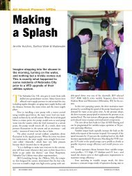
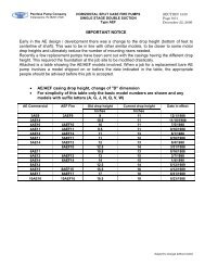
<strong>About</strong> <strong>Lubrication</strong> <strong>Systems</strong>“Getting the Most from Single-Point Lubricators”Luis F. Rizo, Elfer, Inc.
<strong>Lubrication</strong> systems and equipment are essential components of manufacturing and industrial machineryand technology. They are used to provide and apply controlled or metered amounts of lubricant to a partor piece of equipment. Companies that provide lubrication equipment are often capable of creating, andmay specialize in, custom units of lubrication technology. <strong>Lubrication</strong> systems are useful in manyindustries, including packaging, printing, water and sewage pumping, textiles, food processing, chemicalprocessing, mining, brewing and bottling, pellet mills and machinery production.Some of the equipment for which lubrication systems are used includes dies, chains, cables, rails, gears,pumps and any other moving and rotating parts commonly found on conveyer or assembly machinery. Toensure reliable and efficient operation of such equipment, these moving parts often need a constantsupply of lubricating fluids, and the lubrication system is able to provide this at the proper temperature,viscosity, flow rate and pressure. Other, more specific examples of machinery that uses lubricants includerock crushers, gearboxes, large blowers and fans, turbines and industrial centrifuges.The most important components of a lubricating system are the reservoir, pump and filter. The reservoir isthe area in which the lubricant is stored after coming back from the area it lubricates. The pump is used tomove the lubricant through the system and into areas that need to be lubricated. The filter is used toensure that the lubricant stays clean and free from contaminants so that the system is not disrupted.These systems often have instrumentation to provide readings of the flow rate, temperature and level ofthe lubricant. More elaborate systems contain alarm points to warn of improper balances.Both manual and automatic lubrication equipment is available. Often, automatic technology is part of apermanent or centralized lubrication system. These systems are usually a part of the machines theylubricate but require separate maintenance for themselves. Automatic systems are especially usefulbecause they reduce downtime and labor cost, since they do not require operators. Also, there is lesschance of failure due to human error, because these machines do exactly what they are programmed todo. Manual lubrication equipment is fully human-operated, as in spot lubrication guns, or only partially, asin the case of a chain lubricator, which requires the mounting of the machine to the chain and theprogramming of flow rate and length of chain into the device, which is then able to run automatically. Formanual lubricators, there is often a greater chance of missing an area or supplying too much lubrication toanother.<strong>Lubrication</strong> : Grease Automatic LubricatorsIn the petrochemical industry, bearing faults drive the majority of repair events for motors, pumps andcompressors. In a study performed at 12 petrochemical plants, the data showed that approximately 60percent of all motor repair events originated with bearing troubles.1 This number differs significantly forpumps and compressors because of the impact on equipment life due to the performance of mechanicalseals. Historical data gathered at these 12 facilities showed that bearing problems representapproximately 70 percent of all repair events for motors and 30 to 35 percent for pumps andcompressors. This climbs to 80 percent in equipment that is selected and supplied with lifetimelubrication.2When a bearing defect is allowed to progress to a catastrophic failure, the failure will be far more costly.This is because damage tends to grow exponentially with time. As equipment damage grows, so does thepotential for extended downtime. Under these circumstances where repeated bearing failures are presentdue to bearing distress caused by lubrication deficiencies, it should be simple to justify the use ofinnovative techniques to reduce the number of failures.The single-point lubricator is one method of extending bearing life. This technology was introduced intothe petrochemical industry about 30 years ago with mixed results. In recent years, manufacturers haveintroduced significant technological advances that have increased the life of bearings and the reliability ofsingle-point lubricators.
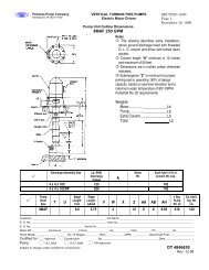
<strong>Lubrication</strong> by Automatic Single-Point LubricatorsSingle-point automatic grease lubricators are refinements of the old compression grease cup (Figure 1).Grease cups are small containers filled with grease that are fitted to the bearing.Click Here to See Figure 1.The principle of operation is to force the grease into the bearing by turning down the cap or pistoncovering the grease charge. The next development in this line of products is the spring-loaded grease cup.The spring-loaded lubricator, a simple refinement of the compression cup, is accomplished by replacingthe screw-down cap or piston with a spring-activated, leather-packed plunger. This plunger, whenengaged by the spring pressure, slowly forces grease into the bearing. Neither of the two types of greasecups is recommended for use under conditions of wide temperature variation, where the consistency ofthe grease may be affected.Single-point lubricators differ from the traditional grease cup by employing either a spring or an expandinggas pressure to exert a force on the cap, piston or diaphragm in contact with the grease volume. Thesecontinuous forced grease injection devices are screwed into the threaded grease port. They range in sizefrom 2 to 18 oz. (60 to 250 cc) of grease capacity and can develop pressures as high as 65 psi (4 bar).The original device, as shown in Figure 1, is spring-loaded. The flow of grease is adjusted by the use of ametering control principle. A piston O-ring seal, which creates a changing level of friction as it movesalong the tapered wall of the reservoir dome, adjusts the flow. The changing resistance is designed tocounterbalance the changing force of the compression spring as it gradually expands. Because thelubricators operate with a single universal spring (other sizes are available) at the lowest reliable pressure(under two psi), no grease is moved into the bearing until it is needed.Variations in discharge flow rate are achieved by inserting different size orifices into the discharge nippleof this field-refillable lubricator. In application, the design is highly affected by the ambient temperatureand the age of the grease in the canister. Tests performed by the author on the spring-loaded lubricatorshowed that in some applications the bearings would be overgreased, while in others, no grease wouldflow at all.Click Here to See Figure 2.
The device shown in Figure 2 is a significant improvement on the original concept of the grease cup.Further details in the operation of lubricators of the same design as Figure 2 show a cylinder containing apressure generator and a piston, which pushes the prepacked lubricant into the bearing in response to thepressure generator.The pressure generator is a rubber bladder containing an electrolytic solution and a sealed plastic tubecontaining a galvanic strip of specially treated metal. After the injector is installed, the activating screw isused to break the plastic tube. This exposes the galvanic strip to the electrolytic solution, resulting in anelectrochemical reaction within the bladder which produces a gas. As the bladder pushes against thepiston, the piston pushes the lubricant out of the injector and into the bearing. When all of the lubricanthas been expelled into the bearing, the unit expires and is thrown away, and a similar unit is installed.The rate of lubricant ejection is a function of the gas production, which in turn depends on time and rateof reaction. Consequently, the rate of lubricant discharge can be pre-designed into this device toaccommodate the user’s discharge rate specifications.Should the lubricant discharge flow be restricted due to viscosity increase, hardening of the grease ormechanical restriction in the supply line, the flow will be reduced or stopped. Under these conditions, thegas pressure will increase to a maximum of 136 psi until normal flow is restored.6 If resistance tolubricant flow is reduced, the lubricant flow will temporarily increase. This will continue until equilibriumbetween the amount of gas generated and the amount of lubricant discharged is reached.Similarly, as with the older devices, the discharge rates are affected by ambient temperature variationsbecause of the increase or decrease in the speed of the electrolytic action resulting from temperaturechanges within the bladder. As the temperature rises, the discharge rate increases and as the temperaturedrops, the rate decreases. A sudden large increase in temperature also causes the lubricant to expandwithin the unit, which will cause a temporary increase in discharge rate. Conversely, a sudden drop intemperature will cause the lubricant within the unit to contract. This results in a temporary decrease indischarge rate, until the gas production within the bladder compensates for the reduced volume within theunit, resulting from the sudden temperature drop.
For lubrication of electric motor bearings ranging from 25 to 400 horsepower, injector manufacturersrecommend a unit, which at an ambient temperature of 77ºF (25ºC) would discharge approximately 0.166cc per day and would be in service for 24 months. Elevation of the ambient temperature to 113ºF (45ºC)would increase the grease discharge rate by a factor of 4 to 0.66 cc per day, resulting in six months ofservice life for the device.Newer electromechanical devices are more sophisticated and capable of delivering lubricant to multiplemachine points. A typical cross-section of one such device is shown in Figure 3. These devices consist of areusable drive motor (battery or direct-wire powered), a refillable/replaceable lubrication canister and asmall pumping device. These units can be set for different discharge periods and be turned on and off witha switch. They are also temperature independent and have precise discharge periods. Additionally, someof these units can be connected to a PLC to monitor operating conditions.Newer units are available in capacities ranging from 60 to 500 cc (2 to 36 oz.). The choice of selectorswitch fixes the rate of gas generated in the electrochemical cell. The dispenser is adjusted to deliverlubricant at the specified rate against atmospheric pressures (14.7 psi absolute). Added backpressure willreduce the discharge rate. Depending on the manufacturer, selected units are capable of developingdischarge pressure that exceeds 350 psi (23 bar).Regardless of the type of device selected, questions remain on the appropriate method or technique thatshould be employed to lubricate bearings. Various user organizations employ different approaches of howto properly apply grease to different bearing configurations. A study of 12 petrochemical facilities showedthat lubrication practices for grease bearings of general-purpose equipment varied, from one extreme ofhaving no program for re-lubrication to the other extreme of employing continuous lubrication via oil mist.Four plants stated they had no lubrication program and ran equipment to failure. Correct greaseapplication is essential to assure that neither excessive nor insufficient grease conditions createcomponent failure. Match the manufacturer’s recommendations for grease volume requirement with unitoutput when using single-point lubricators. Also consider these conditions:
Area ClassificationMake sure that the lubricator you are considering is designed to meet the electrical area classification ofthe area of the plant where you plan to install it.Over <strong>Lubrication</strong> of BearingsToo much grease in a bearing or its housing causes churning, resulting in a sharp increase in temperatureand often, premature lubricant and/or bearing failure. On start-up, grease-lubricated bearings expelgrease into vacant spaces around the housing. To prevent churning, there must be sufficient empty spacein the housing to accommodate this grease. Re-lubrication volume is application-dependent, but acommon rule for grease application is to pack the bearing completely, but fill only one-third of the bearinghousing.Under <strong>Lubrication</strong> of BearingsEven with the correct grease in your single-point lubricators, under lubrication can occur. Theconsequences are excessive heat and eventually metal-to-metal contact between bearing components.Always take into account the changes in ambient temperature at your site. For example, a commonpractice at a plant using electrochemical devices was to purchase 24-month lubricators to be replacedyearly. This was done to compensate for high temperatures during the summer.Failure to Prevent Lubricant ContaminationLubricant contamination is a leading cause of bearing failure. Dirt particles, other contaminants and theapplication of incompatible grease are all factors that increase equipment failures. The use of twoincompatible lubricants will lead to deterioration in lubricating capability.Using the Wrong SealsThe use of the correct bearing design (seal and shields) supplemented with a bearing isolator can be thedifference between long-term reliable service and a “bad actor.” Review all your applications with thebearing manufacturer to assure an optimum fit.Failure to Re-Lubricate BearingsEven without exposure to contaminants, lubricant quality can deteriorate over time. Although single-pointlubricators will continue to operate, failure to keep track of lubricant condition and age can lead topremature equipment failures. Contact the bearing manufacturer for recommendations on optimumlubricant replacement intervals.Failure to Provide Re-<strong>Lubrication</strong> TrainingMaintenance technicians commonly receive training on bearing selection and installation, but notlubrication. Ensure that technicians are thoroughly trained in lubrication fundamentals as well.Recommendations<strong>Lubrication</strong> should not be left to chance. Optimized grease lubrication requires knowledge of bearingconfiguration, lubricant and operating conditions. Single-point lubricators should be selected and appliedjudiciously to obtain the desired extended equipment life. These lubricators have their place, but cannotbe applied indiscriminately. They are quite useful in keeping bearing housing grease cavities full, keepingin mind the importance of bearing design and shield application. It is important to remember that thisadvantage can become a disadvantage if an over greasing situation is created. Single-point lubricators areattractive in inaccessible locations. However, inaccessible should not mean forgotten. Climatic conditionsand age can lead to changes in grease quality, and eventually to separation problems, which arefrequently observed in many plants.It is the responsibility of maintenance professionals to consider the cost of using single-point lubricatorsfor every lubrication point in the plant. One must be cautious of grease compatibility issues when applyingsingle-point lubricators with the refillable feature. The wrong grease or the mixture of incompatiblegreases can create as much trouble as improper lubrication does.Depending on the application, single-point lubricators can extend the life of rotating equipment andincrease reliability while significantly reducing the cost of applying the lubricant. In these days of reduced
udgets and staffs, these devices can provide increased long-term service for the general-purposeequipment of the plant.References1. Bloch, H., (2000). “Practical <strong>Lubrication</strong> for Industrial Facilities.” Chapter 13, Fairmont Press, Inc.2. Bloch, H. and Rizo, L. (1984). “<strong>Lubrication</strong> Strategies for Electric Motor Bearings in thePetrochemical and Refining Industry.” NPRA.3. Bloch, H. (April 1978). “Optimized <strong>Lubrication</strong> of Antifriction Bearings for Centrifugal <strong>Pump</strong>s.” ASLEPaper No. 78-AM- ID-2.4. Booser, E. (Aug. 21, 1975). “When To Grease Bearings.” Machine Design, p. 70-73.5. Digilube <strong>Systems</strong>. Electrolube Automatic Electronic Lube Dispensing <strong>Systems</strong>. “Technical BulletinA.T.S.” Springboro, OH. www.info@digilube.com/.6. Permalube. “Technical Data Bulletin 10473-2-2.” Quincy, IL. http://www.permausa.com/.7. Lubesite <strong>Systems</strong>, Inc. Kingston, NC. www.lubesite.com/products/product_200.html.PLI, LLC. Racine, WI www.memolub.com.LaBour <strong>Pump</strong> Company – 901 Ravenwood Drive, Selma, Alabama 36701Ph: (317) 925-9661 - Fax: (317) 920-6605 - www.labourtaber.comA Product of <strong>Peerless</strong> <strong>Pump</strong> CompanyCopyright © 2005 <strong>Peerless</strong> <strong>Pump</strong> Company