
Create successful ePaper yourself
Turn your PDF publications into a flip-book with our unique Google optimized e-Paper software.
<strong>Pump</strong> <strong>Wear</strong>
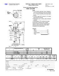
Avoiding <strong>Pump</strong> <strong>Wear</strong> in Centrifugal <strong>Pump</strong>sIntroduction:In the moment of starting a new pump, that pump is headed for a day when it will need repair even if the designand operation is correct. One factor that determines the repair is internal wear. Imagine and ideal applicationwhere the pump is operating at its BEP and the system is stable. Does this condition ever exist? If you answeryes, you are one of the fortunate few. However at some point, even if it does not break, the pump will go to theshop because of internal wear. This article presents different sources of internal wear and suggestions to extendthe useful running time of a pump.Erosion:Erosion is the wear and tear of the pump internal parts by suspended solid particles contained in the fluid beingpumped. The most affected parts are: wear rings, shaft sleeves, packing, mechanical seal faces, lip seals, thepump casting, and the impeller.Erosion can be caused by small particles not visible to the human eye, like dissolved minerals in “hard water.”Larger solids like sand, boiler scale, and rust can also cause serious erosion inside the pump.The fluid being pumped is often not well defined. Terminology like well water, industrial effluent, raw water,boiler feed water, condensate water, etc., is usually the only definition we have of the fluid being pumped. Anyof these fluids can contain several concentrations of solids that cause erosion and wear inside a pump.When the liquid being pumped is known to have a large concentration of solids, the materials inside the pumpshould be changed to more resistant materials. Materials such as carbon steel, high chrome iron, hardenstainless steel, or hard coatings like ceramic or tungsten alloy are some of the most used.Corrosion:Corrosion is caused by a chemical or electrochemical attack on the surface of the metals. It is increased whenthere is an increase in temperature and/or presence of oxygen in the fluid or the surface of the fluid.We can aggravate the corrosion effect if misaligned parts have relative movement, such as loose fit bearings or rrapid changes in the system. Cavitation, erosion, and high fluid velocity advance the corrosion process.Cast Iron is a widely used material for centrifugal pump housings. It is used when the fluid pH id six or higher(not acid). Cast Iron corrodes and forms a protective coating on the surface of the metal. This graphitizedsurface protects the metal from further corrosion as long as the coating is intact. High velocity fluids, cavitation,metal to metal contact and erosion can affect this protective coating.If corrosion exists, the pump-wet parts can be changed for other materials such as stainless steel or compositematerial. Impellers can be replaced by bronze cast impellers or other materials.<strong>Wear</strong> Rings:<strong>Wear</strong> rings provide for a close running, renewable clearance, which reduces the amount of liquid leaking fromthe high pressure zones to the low pressure zones in the pump. They are commonly fitted in the pump case andon the impeller (Figure 16-1).
StrictToleranceStrictToleranceImpellerFigure 16-1These wear rings are lubricated with the fluid being pumped. Eventually they will wear. Tolerances open andmore liquid passes from the discharge end back to the suction end of the pump. The rate of wear is a function ofthe pumped liquid’s lubricity. When the wear is excessive, the pump suffers degradation in its performance.This is particularly true with small pumps running at high speed. The strict tolerance in the replaceable wearrings governs the efficiency of the pump. When the pump goes to shop, these wear rings should be changed.You can expect the pump to loose 1.5 to 2 percent efficiency points for each on e thousandths (0.001 inch) wearin a wear ring beyond the original factory setting. This setting is based on the operating temperature of theapplication. Let’s consider how much money the lost efficiency costs. We sill use some formulas on usefulwork and efficiency.Cost Per Year= 0.000189 x GPM x TDH x $Kwh x sp.gr. x 8,760Eff. <strong>Pump</strong> x Eff. MotorWhere:0.000189= Conversion FactorGPM= Gallons per MinuteTDH= Total Dynamic Head$Kwh= Cost per Kilowatt-hoursp.gr.= specific gravityEff. <strong>Pump</strong>= <strong>Pump</strong> EfficiencyEff. Motor= Motor EfficiencyTo show cost increase, consider this newly installed pump in a properly designed system. We have thefollowing values:GPM= 2,00 gpmTDH= 120 ft.$Kwh= $0.10sp.gr.= 1 (water)Eff. <strong>Pump</strong>= 77%Eff. Motor= 93%The electricity cost to run this pump for a year is $55,450.80.After being in line for six months, this pump is disassembled and it is noted that the tolerance in the wear bandshas opened 0.004 inch from the original factory setting. This wear represents and 8% decrease in efficiency.
Now the pump is 69% efficient. Let’s do the math with all the other factors constant. This reduction in theefficiency represents an annual electricity costs of $61,845.60. The additional electricity is $6,394.80. Fourthousandths wear (0.004 inch) has cost the company almost $6,500.00 per year for just one pump. Just tomention, a new wear ring may cost up to $60.00 plus the labor to change it (this will never add up to the$6,500.00).Effective and well planned maintenance can reduce the operating cost of your pumps and other equipment asthis example demonstrates. With differential pressure gauges on the pump, an amp meter, and flow meter youcan determine if strict tolerance parts are worn. This indicates the need to take the pump into the shop forcorrective procedures. If you don’t do it, you are wasting your annual operating budget. The wear rings shouldbe called efficiency rings.Fluid Velocity Accelerates <strong>Wear</strong>:Small impellers with high motor speeds may produce the necessary pump pressure. This type of combinationproduces high fluid velocities that will wear pump parts much faster than desirable. This is in the Affinity Laws.In addition the impeller suffers rapid wear due to high tip velocities. When a pump is disassembled andexcessive wear is found, 95% of the time velocity fluid is to blame.Turbulence:Uneven wear in parts is often due to turbulence. Bad piping designs or poorly sized valves can cause turbulenceor uneven wear in pumps. Whenever possible, use straight pipe sections before and after the pump. Unevenflow creates turbulent flow and excessive wear occurs.It is not recommended to place an elbow at the suction of any pump (Figure 16-2). This will cause a turbulentflow into the pump. If elbows are needed on both sides of the pump, you should use long radius elbows withflow straighteners. You should have 10 pipes diameters before the first elbow on the suction piping (Example:If the pump has a 4 inch suction nozzle, you should respect 40 inch of straight pipe before the first elbow).Short radius elbows cause vibrations and pressure imbalances that lead to wear and maintenance on the pump.Figure 16-2
A pipe size increase can be used in the discharge piping. This will reduce the fluid velocity and friction losses.An isolation valve with a low loss characteristic such as a gate valve should be placed after the increaser andcheck valve.Throttling:A centrifugal pump should never be operated continuously at or near the shut off head. This normally happenswhen a tank or vessel is near the maximum capacity and an operator or level sensor starts closing the dischargevalve while the pump is running. This is similar to activating your car brakes while the gas petal is to the metal.All this wasted energy is transferred to the fluid being pumped. This type of operation shortens the life of thepump and increases the downtime. This energy is converted into heat and vibration raising the fluidtemperature. Some pump casings can dissipate the heat. Other casings contain heat switches that will trip-outand “shut off” the pump.An intensive radial load is created when operating near the shut-off head and the shaft deflects about 60° fromthe cut-water. This concept is called shaft deflection. The pump will be noisy, will vibrate, and maintenance onseals, bearings, and shaft sleeves is expected.<strong>Pump</strong>s are usually over-designed. From the initial specification stages, future needs are taken intoconsideration, maximum flow is overrated, and operating conditions are uncertain. Design engineers followinga financial guide to lower future capital investment do this. With this in mind, no wonder we have toextensively throttle the discharge in order to achieve our necessary flow rate. Yes, this saves future capitalinvestments, but creates present problems with the daily maintenance budget. Excessive throttling if thedischarge valve results in severe punishment to the pump.Consider Figure 16-3. The pump is draining a tank and discharging into the process stream. If a control valveshould be strangled to a certain predetermined pressure (resistance), the pressure relief valve automaticallyopens and the excess discharge pressure recirculates back to the suction tank. The pump never knows that thedischarge control valve is throttled. If this situation exists in your plant or if the operators regulate the flow bymanipulating control valves, this will be the proper design to extend the useful life of your pump.Figure 16-3
LaBour <strong>Pump</strong> Company – 901 Ravenwood Drive, Selma, Alabama 36701Ph: (317) 925-9661 - Fax: (317) 920-6605 - www.labourtaber.comA Product of <strong>Peerless</strong> <strong>Pump</strong> CompanyCopyright © 2005 <strong>Peerless</strong> <strong>Pump</strong> Company