TEST SWITCHES TEST SWITCHES - Brooks Utility
TEST SWITCHES TEST SWITCHES - Brooks Utility
TEST SWITCHES TEST SWITCHES - Brooks Utility

Create successful ePaper yourself
Turn your PDF publications into a flip-book with our unique Google optimized e-Paper software.
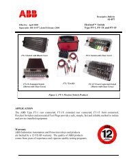
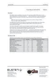
<strong>TEST</strong><br />
<strong>SWITCHES</strong><br />
• Standard<br />
• Compact<br />
• Mini-Compact<br />
• Specials<br />
• Roto-Test
<strong>TEST</strong><br />
<strong>SWITCHES</strong><br />
Contents<br />
Design & Construction Features .................................2<br />
Connection Suggestions for Test Switches...................4<br />
Single-Phase..........................................................4<br />
Network or Three-Phase ........................................4<br />
Three-Phase, Four Wire .........................................5<br />
Special Switches ........................................................6<br />
Back-Connected Switches ..........................................8<br />
Flush-Mounted Switches ............................................8<br />
Test Switch Covers......................................................9<br />
Instructions For Ordering Special Switches...............10<br />
Standard Switch Assemblies .....................................11<br />
2, 3, 4 and 6 Poles ..............................................12<br />
7, 8 and 9 Poles ..................................................13<br />
10 and 11 Poles ..................................................14<br />
Compact and Mini-Compact Test Switches...............15<br />
Compact Design & Construction Features ...........16<br />
Standard Compact Switch Assemblies .................17<br />
Semi-Flush Mounted Type ................................18<br />
Front-Connected Type .....................................20<br />
Mini-Compact Design & Construction Features ...22<br />
Standard Mini-Compact Switch Assemblies.........23<br />
Semi-Flush Mounted Type ................................24<br />
Front-Connected Type .....................................26<br />
Roto-Test Switch.......................................................28<br />
Roto-Test Switch Design and Construction ...............29<br />
Roto-Test Switch Catalog Numbers...........................32<br />
METER DEVICES COMPANY<br />
A Subsidiary of the E. J. BROOKS Company<br />
3359 Bruening Avenue S.W.<br />
P.O. Box 6382, Station B<br />
Canton, Ohio 44706<br />
Phone: (330) 455-0301<br />
Fax: (330) 455-1461<br />
Toll Free - 1 888 FOR-METER<br />
www.meter-devices.com<br />
MD-TS99-20M<br />
© 1999 Meter Devices Company<br />
Printed in U.S.A
Meter Devices Test Switches<br />
Meter Devices Company, founded in<br />
1918, has been a member of the E.J.<br />
<strong>Brooks</strong> family of companies since<br />
1981. The company has earned an<br />
enviable reputation among the<br />
world’s electric utilities as the<br />
premier supplier of knife type test<br />
switches.<br />
Meter Devices Company designs and<br />
manufacturers the finest quality and<br />
most complete line of test switches in<br />
the industry. Applications include<br />
meter, relay, instrument transducer<br />
and control system calibration,<br />
disconnecting, troubleshooting and<br />
testing.<br />
Meter Devices test switches<br />
incorporate many features for safety,<br />
durability, reliability and<br />
dependability. Test switches are rated<br />
at 30 amperes, 600 volts, A.C. and<br />
meet all applicable l.E.E.E., E.E.I.,<br />
A.N.S.I. C12.9, and Underwriters<br />
Laboratories standards.<br />
All test switches are completely nonferrous,<br />
manufactured from high-conductivity<br />
copper and phosphor<br />
bronze. Test switches are furnished<br />
unplated as standard; however, tin or<br />
nickel plating for corrosion protection<br />
are available upon request.<br />
1
Meter Devices Test Switches<br />
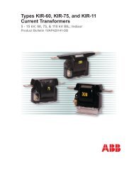
Design & Construction Features<br />
Meter Devices exclusive<br />
double spring, phosphor<br />
bronze contact jaw<br />
assures positive contact<br />
and long life<br />
A serrated or<br />
corrugated test ear<br />
designed to positively<br />
prevent test clips from<br />
coming off<br />
Molded black<br />
Plaslok ® or specialsized<br />
black<br />
Resiten ® bases<br />
provide excellent<br />
insulating, tracking<br />
and dielectric<br />
properties<br />
Molded plastic handles<br />
available in 12 solid<br />
colors, or 2-piece colored,<br />
have provision for wire<br />
i.d. Iabel<br />
Hinge jaw assembly<br />
has brass rivet in<br />
combination with a<br />
compression Belleville<br />
spring washer which<br />
maintains correctly<br />
adjusted jaw tension<br />
Wire saddle traps the wire or<br />
crimp connector to insure<br />
positive location; the terminal<br />
stud is long enough to accept<br />
multiple connections<br />
Bases<br />
Insulating bases are molded from<br />
tough, time-tested materials with<br />
excellent insulating, tracking and<br />
dielectric properties. Select from<br />
four sizes of molded-base test<br />
switches – 4-1/2 “, 7-1/2 “, 9-1/2 “<br />
and 11-1/2” for either frontconnect,<br />
semi-flush, or flush<br />
mounting. Special Resiten ® base<br />
test switches complement and<br />
satisfy still other special<br />
requirements which cannot be met<br />
with molded-base switches.<br />
Handles<br />
Test switches are supplied as<br />
standard with red potential and<br />
black current handles. Other<br />
colors available: blue, brown,<br />
green, orange, white, yellow, red<br />
w/white tracer, green w/white<br />
tracer black w/white tracer, white<br />
w/black tracer. Handles include<br />
provisions for a wire i.d. Iabel.<br />
Optional Handles<br />
Two-Piece Colored Handles -<br />
Meter Devices offers ultrasonically<br />
welded two-piece handles as an<br />
option for customers who desire<br />
full-color mulitcolor handles on<br />
their switches.<br />
The Hinge Jaw<br />
Assembly assures a constant,<br />
uniform smooth pressure against<br />
the switch blade by use of a brass<br />
rivet that can’t come off, in<br />
combination with a compression<br />
Belleville spring washer which<br />
maintains correctly adjusted jaw<br />
tension.<br />
Double-Spring<br />
Reinforced Contacts<br />
Designed and developed by Meter<br />
Devices exclusively for Meter<br />
Devices products and considered,<br />
by far, the best contacts yet<br />
designed; contact jaws made of<br />
high conductivity phosphor bronze<br />
and reinforced with high<br />
conductivity bronze clips. The jaw<br />
is a spring in itself and will not<br />
spread, assuring perfect-contact,<br />
low resistance, no overheating and<br />
easy operation at all times. Added<br />
reinforcement of the phosphor<br />
bronze clips is positive assurance<br />
of long life and perfect action.<br />
2
Meter Devices Test Switches<br />
The Short Circuit Clip<br />
Developed by Meter Devices, the<br />
short circuit clip eliminates the<br />
weakest, most troublesome part of<br />
most present<br />
day test<br />
switches.<br />
It is a make<br />
before-break<br />
type, made<br />
from one piece of<br />
phosphor bronze. It cannot get out<br />
of alignment; projections on the<br />
knife blade prevent raising the<br />
blade to a point where it is out of<br />
contact with the clip. A return<br />
strap completes the circuit to the<br />
spring jack.<br />
Test Jack<br />
Eliminates the possibility of<br />
accidentally opening CT<br />
secondaries and permits safe, easy<br />
measurements to be made in<br />
current circuits without disturbing<br />
permanent wiring. A dual-circuit<br />
test plug, such as Meter<br />
Devices Cat. #903-1116, is<br />
inserted into the test jack,<br />
putting the measuring<br />
instrument in<br />
series with the<br />
current circuit.<br />
Barriers<br />
Barriers of flame-resistant nylon<br />
are normally supplied between<br />
potential elements of all switches<br />
where center-to center spacing is<br />
less than one inch. Meter Devices’<br />
barriers are higher than<br />
competitive brands to provide an<br />
extra measure of safety.<br />
Optional Channel Barriers<br />
Meter Devices<br />
can now supply<br />
channel barriers<br />
as an option<br />
replacing the<br />
standard snap-in<br />
barriers. The<br />
channel barriers<br />
are made of the<br />
same flame-resistant material as<br />
the standard snap-in barriers. The<br />
channel barriers also provide<br />
the mechanical and electrical<br />
advantages as the standard<br />
snap-in barriers.<br />
Wire Saddle & Terminal<br />
Studs<br />
Provided as standard for wiring test<br />
switches, wire saddle traps the<br />
wire or crimp connector to insure<br />
positive location and protect<br />
against rotation. The terminal stud<br />
is long enough to accept multiple<br />
connections at one point. For ease<br />
of wiring, solderless terminals are<br />
an option (in place of the wire<br />
terminal stud).<br />
Hexagon Nuts<br />
Of 3/8 “ heavy brass for fastening<br />
wire.<br />
Test Ears - Provided<br />
A serrated or corrugated test ear of<br />
ample size is designed to positively<br />
prevent test clips from coming off<br />
unless the spring tension is<br />
released.<br />
3
Meter Devices Test Switches<br />
Connection Suggestions for Test Switches<br />
Single-Phase Connections<br />
1Ø3W with 1 C.T.<br />
Single Stator (2W1ø) - Form 3S Meter<br />
Cat. No. 104-5401<br />
1Ø2W with 1 P.T. & 1 C.T.<br />
Single Stator (2W1Ø) - Form 3S Meter<br />
Cat. No. 104-5401<br />
1Ø3W with 2 C.T.’s<br />
Single Stator (3W1Ø) - Form 4S Meter<br />
Cat. No. 106-2434<br />
Network or Three-Phase Connections<br />
4<br />
1Ø3W or 3W Network with 2 C.T.’s<br />
2 Stator Meter - Form 5S<br />
Cat. No. 107-1266<br />
3Ø3W “ ∆ “ with 2 P.T.’s & 2 C.T.’s<br />
2 Stator Meter - Form 5S<br />
Cat. No. 107-1266<br />
3Ø3W “ ∆ “ with 2 C.T.’s<br />
2 Stator Meter - Form 5S<br />
Cat. No. 107-1266
Meter Devices Test Switches<br />
Three-Phase,<br />
Four-Wire Connections<br />
3Ø4W “Y” with 3 C.T.’s<br />
2-1/2 Stator Meter - Form 6S<br />
Cat. No. 109-4456<br />
3Ø4W “Y” with 2 P.T.’s & 3 C.T.’s<br />
2-1/2 Stator Meter - Form 6S<br />
Cat. No. 109-4456<br />
WIDE CT<br />
LINE<br />
WIDE CT<br />
WIDE CT<br />
LOAD<br />
3Ø4W “Y” or “ ∆ “ with 3 C.T.’s<br />
“Y” 3 Stator Meter - Form 9S<br />
“ ∆ “ 2 Stator Meter - Form 8S<br />
Cat. No. 110-54583<br />
3Ø4W “Y” with 3 P.T.’s & 3 C.T.’s<br />
3 Stator Meter - Form 9S<br />
Cat. No. 110-54583<br />
3Ø4W “Y” with 3 C.T.’s<br />
3 Stator Meter - Form (ALT) IOS<br />
Cat. No. 110-54583<br />
5
Meter Devices Test Switches<br />
Special Switches<br />
Plated Meter<br />
Test Switches<br />
Meter Test Switches –<br />
Colored Handles<br />
Meter Test Switches<br />
Screw Terminals<br />
Meter Devices Company test<br />
switches are completely nonferrous<br />
being manufactured of<br />
copper and phosphor bronze. As<br />
such, they are furnished as<br />
standard unplated. If plating is<br />
required, tin or nickel, are<br />
available. To order, please suffix<br />
catalog number: TP - tin, NP -<br />
nickel, i.e., #110-54580-TP.<br />
Plating is a slight additional cost.<br />
High Voltage Test Switch<br />
Meter Devices test switches are<br />
furnished as standard with red<br />
potentials and black current<br />
handles. Other colors available<br />
are: blue, brown, green, orange,<br />
white, yellow, purple, red w/white<br />
tracer, green w/white tracer, black<br />
w/white tracer, and white w/black<br />
tracer. Two-piece color handles<br />
optional. Please specify handle<br />
colors from left to right when<br />
ordering. Red and Black are<br />
standard. Other color handles are<br />
a slight additional cost.<br />
Screw type terminals with a<br />
captive pressure pad are available<br />
on all front connected switches.<br />
No looping of wires is necessary,<br />
no loose parts to become<br />
misplaced. Simply insert the<br />
stripped wire beneath the pressure<br />
pad and tighten the terminal screw<br />
with a screwdriver. To order this<br />
type of terminal add suffix “ST” to<br />
the switch catalog number, i.e.<br />
#110-54521-ST. Price is slightly<br />
higher than standard terminal stud<br />
and nut.<br />
Reversed Potential<br />
Switches<br />
Meter Devices type HV High Voltage<br />
test switch provides a maximum<br />
amount of safety on services where<br />
2 5/8”<br />
277/480 volts are used. The test<br />
switch is made on a Resiten ® base<br />
material which has excellent<br />
4 1/4”<br />
insulating properties. Potentials are<br />
spaced further apart and are<br />
protected by barriers that are higher and thicker for added safety. Other<br />
usual utility safety procedures should continue to be followed.<br />
Reversed potentials are available<br />
on any of our standard test<br />
switches. They are popular with<br />
utilities that are seeking an added<br />
margin of safety for their personnel.<br />
Potential switch handles are<br />
mounted in reverse so that when<br />
the switch is open, the potential<br />
blades are not energized as would<br />
be the case if mounted in the conventional<br />
way.<br />
6
Meter Devices Test Switches<br />
Small Base Test Switches<br />
Reactive Volt-Ampere Metering<br />
Switches<br />
Small base test switches are made on Resiten ® bases.<br />
They are available in any combination of currents or<br />
potentials, front or back connected, with handle<br />
ganging for single throw capability as an option.<br />
Switch elements are the same as on large base test<br />
switches. These switches are used where physical<br />
space is at a premium.<br />
Single or Double Throw<br />
Test Switches<br />
Reactive volt-ampere metering switches are a doublethrow<br />
type that permits testing reactive meters as<br />
KWH meters by shifting the potential. Commonly<br />
known as “heel-and-toe switches”, they are available<br />
in two types: “make-after-break” in which the switch<br />
blade has a neutral position and leaves the first jaw<br />
before it enters the second jaw; and “make-before<br />
break” in which the blade enters the second jaw<br />
before it leaves the first jaw. All Meter Devices heel<br />
and toe switches are furnished “make-after-break”<br />
unless specified otherwise.<br />
Single or double throw switches of<br />
any number of poles are available<br />
in front or back-connected styles.<br />
Fusing provisions for a 30 or 60<br />
ampere fuse is also available.<br />
Fused Potential<br />
Switches<br />
Potential switches are available in<br />
single or multiple pole arrangements<br />
with provisions for<br />
mounting a 30 or 60 ampere fuse.<br />
Test switches are available in a<br />
front or back connected style, as<br />
shown above.<br />
Fuse Blocks<br />
Some utilities specify that where<br />
potential coils, telemetering<br />
circuits, or communication circuits<br />
are connected directly to a service<br />
without potential transformers,<br />
fuses must be used in the leads.<br />
Equipment protection and the<br />
presence of relaying devices may<br />
make the use of fuses advisable.<br />
The Catalog No. 101-1375 single<br />
pole Fuseholder Block here<br />
illustrated is for mounting on the<br />
primary bar of 600 volt current<br />
transformers.<br />
Unmounted Test<br />
Switches<br />
Meter Devices Unmounted<br />
Potential Test Switches can be<br />
supplied to meet your special<br />
requirements. These switches are<br />
available in single pole or ganged<br />
as two up to six poles, single<br />
throw, or double throw, front or<br />
back-connected. Illustrations are<br />
back connected.<br />
7
Meter Devices Test Switches<br />
Back-Connected Switches<br />
Any Meter Devices test switch can<br />
be supplied in a back-connected<br />
version whereby the switch is<br />
mounted on one side of a panel<br />
and the wiring connections are<br />
made on the opposite side. Backconnected<br />
switches are designated<br />
by the catalog number prefix and<br />
the suffix "B", i.e., #130-54580B.<br />
Back-connected switches are<br />
furnished as standard with<br />
insulated bushings for steel panel<br />
mounting. Switches may also be<br />
supplied without bushings for<br />
panels that are insulated. Please<br />
specify without bushings when<br />
required.<br />
Flush-Mounted Switches<br />
Meter Devices Switches can be<br />
supplied mounted in our Flush<br />
Mounting Cases with cover. These<br />
cases are especially suitable for<br />
steel panel mounting so as to<br />
conform to other flush mounted instruments<br />
such as meter relays, etc.<br />
The assembly consists of an<br />
insulated case and a semi-flush<br />
sealable cover of cast metal and<br />
Lexan ® insert. Covers are finished<br />
in dull-lustre black to match the<br />
switch board panel.<br />
SIMPLE INSTALLATION<br />
For installing Flush Mounting<br />
Cases and Covers, all one needs to<br />
do is cut a hole in the panel<br />
[dimensions as shown here]. Insert<br />
the case from the front of panel<br />
and attach with four screws. The<br />
cover fits over the opening and is<br />
then secured by means of two<br />
sealable cover studs.<br />
8<br />
DRILLING DIMENSIONS FOR<br />
FLUSH MOUNTING <strong>TEST</strong><br />
SWITCH CASES<br />
Flush-Mounted Switches<br />
3/8” DIA. HOLE - C’SK. 3/16” DEEP<br />
2 REQD.<br />
4-13/16”<br />
Cat. # Width of Base A B<br />
115-204FM 4-1/2 5-1/16 5-5/8<br />
115-207FM 7-1/2 8-3/16 8-3/4<br />
115-209FM 9-1/2 10-1/2 11-1/16<br />
115-211FM 11-1/2 13-9/16 14-1/8<br />
B<br />
A<br />
3/16” DIA<br />
HOLE<br />
4 REQD.<br />
1-1/2”<br />
1-1/2”
Meter Devices Test Switches<br />
Test Switch Covers<br />
All Meter Devices test switches can be supplied with either a clear or black<br />
opaque plastic cover. Plastic covers are injection molded of Lexan ® which<br />
is a flame-resistant, unbreakable UL-listed material. Slotted covers for front<br />
connect or solid covers for back connect test switches are available. To<br />
prevent loss of registration, Meter Devices covers are made so that all<br />
switch blades must be in a closed position before covers can be sealed.<br />
Optional Cover - Captive Hardware<br />
All test switch covers are available with<br />
the optional feature of captive hardware.<br />
This hardware prevents the loss of the<br />
cover stud nuts during testing and saves<br />
the time and expense of looking<br />
for lost cover nuts or the expense of<br />
replacement nuts.<br />
Slotted Covers for Front Connected Test Switches<br />
CLEAR w/ Optional Captive BLACK w/ Optional Captive Dimensions<br />
Cat. # Hardware Cat. # Hardware A B C<br />
115-204LF 115-204LFCH 115-204PF 115-204PFCH 4-5/8 3-1/2 3-1/4<br />
115-207LF 115-207LFCH 115-207PF 115-207PFCH 7-5/8 6-1/2 6-1/4<br />
115-209LF 115-209LFCH 115-209PF 115-209PFCH 9-5/8 8-1/2 8-1/4<br />
115-211LF 115-211LFCH 115-211PF 115-211PFCH 11-5/8 10-1/2 10-1/4<br />
1/4” HOLE<br />
1/2”<br />
4 1/4”<br />
A<br />
B<br />
3 1/16”<br />
Solid Covers for Back Connected Test Switches<br />
C<br />
CLEAR w/ Optional Captive BLACK w/ Optional Captive Dimensions<br />
Cat. # Hardware Cat. # Hardware A B<br />
115-204LB 115-204LBCH 115-204PB 115-204PBCH 4-5/8 3-1/2 -------<br />
115-207LB 115-207LBCH 115-207PB 115-207PBCH 7-5/8 6-1/2 -------<br />
115-209LB 115-209LBCH 115-209PB 115-209PBCH 9-5/8 8-1/2 -------<br />
115-211LB 115-211LBCH 115-211PB 115-211PBCH 11-5/8 10-1/2 -------<br />
9
Meter Devices Test Switches<br />
Instructions For Ordering Special Switches<br />
Assembly #1 Assembly #26 Assembly #27<br />
Assembly Number<br />
EXAMPLE<br />
Test switch No. 107-54502 is made up of<br />
assemblies 1-1-1-26-27, these assemblies,<br />
found on following page, may be ordered<br />
to fit your requirements.<br />
METER DEVICES can supply test<br />
switches to meet practically any<br />
meter or relay testing requirement.<br />
Those standard switches which<br />
meet the majority of requirements<br />
are listed in the catalog. But if you<br />
need a special test switch you may<br />
design one to meet your own<br />
particular use by application of the<br />
information outlined below:<br />
1. STANDARD ASSEMBLIES: You<br />
may design a switch made up of<br />
any number, or combinations,<br />
of potential or current elements<br />
by selecting any of the<br />
combinations possible from the<br />
standard assemblies illustrated<br />
on page 11. These assembly<br />
numbers are not the catalog<br />
numbers but are for convenience<br />
of switch layout.<br />
2. DIMENSIONS: The minimum<br />
center-to-center horizontal<br />
dimensions between studs of<br />
adjoining elements is 13/16”. A<br />
minimum of 2-1/4” is required<br />
in addition to the sum of the<br />
dimensions between elements<br />
selected, as it requires 1-1/8” at<br />
each end of the base from<br />
center line to end elements, for<br />
mounting holes and cover<br />
sealing stud clearance. Barriers,<br />
Assembly No. 19, are provided<br />
on all switches where center-tocenter<br />
distances between<br />
potential and other assemblies<br />
are less than one inch. Barriers<br />
require no additional spacing.<br />
3. SWITCH BASES: All standard<br />
bases are 3-1/2” in height .<br />
Standard base widths are 4-1/2”,<br />
7-1/2”, 9-1/2” and 11-1/2”<br />
inches. The available working<br />
space is the base width less<br />
2-1/4”.<br />
Base Working Maximum No.<br />
Length Space of Poles<br />
4-5/8” 2-7/16” 4<br />
7-1/2” 5-5/16” 7<br />
9-1/2” 7-5/16” 10<br />
11-1/2” 9-5/16” 12<br />
4. SPECIAL RESITEN ® BASES: Are<br />
available for special spacing of<br />
elements or switches with more<br />
than twelve poles.<br />
10
STANDARD Test Switches<br />
Standard Switch Assemblies<br />
Assembly #1<br />
Single pole potential<br />
Assembly #4<br />
Solid thru bar<br />
Assembly #12<br />
Single pole current<br />
element right<br />
Assembly #13<br />
Single pole current<br />
element left<br />
Assembly #14<br />
Double pole<br />
current element<br />
Assembly #16<br />
Double pole potential<br />
Assembly #17<br />
Three pole potential<br />
Assembly #18<br />
Three pole current elemtent<br />
Assembly #19<br />
Barrier<br />
Assembly #20<br />
Single pole double throw<br />
break before make<br />
Assembly #21<br />
#20 & 21 are double throw switches that break before<br />
make. Can be supplied with make before break<br />
Assembly #26<br />
Load test jack double pole<br />
current element right hand<br />
Assembly #27<br />
Load test jack double pole<br />
current element left hand<br />
Assembly #28<br />
Load test jack single<br />
pole current element<br />
Assembly #29<br />
Load test jack single pole<br />
current element right<br />
Assembly #30<br />
Load test jack single pole<br />
current element left<br />
Assembly #31<br />
30 Amp fuse clip<br />
Assembly #32<br />
60 Amp fuse clip<br />
Assembly #40<br />
Channel Barrier<br />
11
STANDARD Test Switches<br />
Standard Switch Assemblies - 2, 3, 4 and 6 poles<br />
Cat. No. 102-687<br />
Cat. No. 103-54539<br />
Cat. No. 104-5401<br />
Cat. No. 104-5402<br />
Cat. No. 104-5403<br />
Cat. No. 104-54504<br />
Cat. No. 104-54505<br />
Cat. No. 106-5405<br />
Cat. No. 104-525<br />
Cat. No. 106-1345<br />
Cat. No. 106-54518<br />
Cat. No. 106-527<br />
12<br />
2,3,4 and 6 poles -All heights 3 1/2”<br />
Catalog No. Number of Poles Base Width (Inches) Arrangement of Assemblies<br />
102-687 2 4-1/2 16 (with #19 center barrier)<br />
103-54539 3 4-1/2 28-28-28<br />
104-5401 4 4-1/2 1-19-1-19-26<br />
104-5402 4 4-1/2 1-19-26-19-1<br />
104-5403 4 4-1/2 1-19-1-19-27<br />
104-54504 4 4-1/2 1-19-27-19-1<br />
104-54505 4 7-1/2 1-1-27<br />
104-525 4 7-1/2 21-21 all handles ganged<br />
106-5405 6 7-1/2 1-1-12-12-29-28<br />
106--1345 6 7-1/2 27-27-27<br />
106-54518 6 7-1/2 28-13-30-13-30-13<br />
106-527 6 9 -1/2 21-21-21 all ganged handles
STANDARD Test Switches<br />
Standard Switch Assemblies - 7, 8 and 9 poles<br />
Cat. No. 107-54915<br />
Cat. No. 107-54900<br />
Cat. No. 107-54515<br />
Cat. No. 107-54502<br />
Cat. No. 107-54547<br />
Cat. No. 107-54942<br />
Cat. No. 107-620<br />
Cat. No. 107-1280<br />
Cat. No. 108-54931<br />
Cat. No. 108-1278<br />
Cat. No. 109-54516<br />
Cat. No. 109-54517<br />
7, 8 and 9 poles<br />
Catalog No. Number of Poles Base Width (Inches) Arrangement of Assemblies<br />
107-54915 7 7-1/2 1-19-26-19-1-19-27-19-1<br />
107-54900 7 9-1/2 1-19-26-19-1-19-26-19-1<br />
107-54515 7 9-1/2 1-26-1-27-1<br />
107-54502 7 9 1/2 1-1-1-26-27<br />
107-54547 7 7-1/2 1-19-1-19-1-19-26-27<br />
107-54942 7 9-1/2 1-19-1-19-1-26-26<br />
107-620 7 9-1/2 1-14-1-14-1<br />
107-1280 7 9-1/2 19-1-19-1-19-1-26-26 (reversed potential handles)<br />
108-54931 8 9-1/2 1-1-1-26-27<br />
108-1278 8 9-1/2 1-19-12-19-1-19-12-29-19-1-19-28-19-1<br />
109-54516 9 9-1/2 1-19-26-19-1-19-26-19-1-19-26<br />
109-54517 9 9-1/2 1-19-1-19-1-19-27-27-27<br />
13
STANDARD Test Switches<br />
Standard Switch Assemblies - 10 and 11 poles<br />
Cat. No. 110-54580<br />
Cat. No. 110-54583<br />
Cat. No. 110-54522<br />
Cat. No. 110-54943<br />
Cat. No. 110-54941<br />
Cat. No. 110-54895<br />
Cat. No. 110-54523<br />
Cat. No. 110-54924<br />
Cat. No. 110-1268<br />
Cat. No. 110-1385<br />
Cat. No. 110-671<br />
Cat. No. 111-54541<br />
14<br />
10 and 11 poles<br />
Catalog No. Number of Poles Base Width (Inches) Arrangement of Assemblies<br />
110-54580 10 9-1/2 1-19-26-19-1-19-26-19-1-19-26-19-1<br />
110-54583 10 9-1/2 1-19-1-19-1-19-1-19-26-26-26<br />
110-54522 10 9-1/2 1-19-1-19-1-19-4-19-27-30-13-30-13<br />
110-54943 10 9-1/2 1-19-1-19-1-19-4-26-26-26<br />
110-54941 10 9-1/2 1-19-1-19-1-19-1-19-27-30-13-30-13<br />
110-54895 10 9-1/2 12-19-1-19-12-19-1-19-12-19-1-19-1-19-29-29-28<br />
110-54523 10 9-1/2 1-19-26-19-1-19-26-19-1-19-26-19-4<br />
110-54924 10 9-1/2 1-19-1-19-1-19-1-27-27-27<br />
110-1268 10 9-1/2 1-19-1-19-1-19-4-26-26-26<br />
(reversed potential handles)<br />
110-1385 10 11-1/2 1-14-1-14-1-14-1<br />
110-671 10 9-1/2 1-19-1-19-1-19-4-19-14-14-14<br />
111-54541 11 11-1/2 1-1-1-26-27-26-27
COMPACT & MINI-COMPACT Test Switches<br />
Compact and Mini-Compact Test Switches<br />
• Compact and Versatile<br />
• Front and Semi-Flush<br />
Connected Styles<br />
• Safe, Durable, Rugged<br />
and Reliable<br />
• Class 1E Qualified per<br />
IEEE Standard 3213-1974<br />
Compact Test<br />
Switch<br />
Mini-Compact<br />
Test Switch<br />
Meter Devices compact and minicompact<br />
test switches provide<br />
quick and easy multicircuit testing<br />
of switchboard relays, meters and<br />
instruments by any conventional<br />
system. Meter Devices compact<br />
and mini-compact switches are<br />
designed for both front and back<br />
connected configurations.<br />
The rugged construction, huskiness<br />
and capacity of the Meter Devices<br />
"standard" larger size has been<br />
retained. Without sacrificing these<br />
features, the compact and minicompact<br />
switch is appreciably<br />
shorter in length to conserve and<br />
utilize panel space on switchboard<br />
installations. The mini-compact<br />
switch is also narrower.<br />
The compact test switch and the<br />
mini compact test switch are<br />
extremely flexible to the extent<br />
that one can be furnished to fit the<br />
exact need. If only a two pole<br />
switch is needed, then a two pole<br />
switch can be furnished in a two<br />
pole case. This same two pole<br />
switch can be furnished in a larger<br />
case, if desired. If a 24 pole switch<br />
is needed, it can be furnished in a<br />
24 pole case, or any combination<br />
in between.<br />
Any arrangement of switch<br />
elements can be made available.<br />
Standard handle color is black.<br />
Color coding of the handles can be<br />
provided as an option. Individual<br />
switches can be operated<br />
independently, replaced or<br />
rearranged in the field. Ganging of<br />
the test switch handles is also<br />
available.<br />
15
COMPACT Test Switches<br />
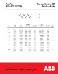
Compact Semi-Flush Mounted Test Switches<br />
Switch Handle<br />
Short Circuit Clip<br />
Switch Blade<br />
Inner Spring<br />
Contact Jaw<br />
Outer Spring<br />
Clip Contact Jaw<br />
Test Jack<br />
Phenolic Barrier<br />
Brass Rivet<br />
Molded<br />
Plastic Base<br />
Test Ear<br />
One Piece Hinge Jaw<br />
Screw Type Terminal<br />
Base<br />
Molded plastic which has<br />
excellent insulating qualities and<br />
non-tracking characteristics.<br />
Switch Blade<br />
Standard size special tempered<br />
copper.<br />
Switch Handle<br />
Standard color unless specified is<br />
black. Other colors available are:<br />
red, yellow, orange, brown, green,<br />
blue, white, red with white tracer,<br />
green with white tracer, black with<br />
white tracer and white with black<br />
tracer.<br />
The design of all handles will<br />
permit multiple ganging if desired<br />
and will hold identification cards.<br />
The handle has deep serrations for<br />
utmost safety and convenience,<br />
offering a secure grip when<br />
operating the blade.<br />
16<br />
Contact Jaw<br />
Double spring reinforced contacts<br />
designed and developed by Meter<br />
Devices Company are considered<br />
by far the best contacts available.<br />
Contact jaws are made of high<br />
conductivity spring bronze and are<br />
reinforced with high conductivity<br />
spring bronze clips. The jaw is a<br />
spring in itself and will not spread,<br />
thus assuring perfect contact, low<br />
resistance, no over-heating and<br />
easy operation at all times. The<br />
added reinforcement of the clip is<br />
positive assurance at long life and<br />
perfect action.<br />
Hinge Jaw<br />
Constant and uniform smooth<br />
pressure against the switch blade is<br />
assured by the use of a spring<br />
washer under the head of the<br />
hinge rivet, which maintains the<br />
correctly adjusted jaw tension.<br />
Short Circuit Clip<br />
This clip developed by Meter<br />
Devices Company eliminates the<br />
weakest and most troublesome<br />
part of present day test switches. It<br />
is a ‘make-before-break’ type,<br />
made from one piece of high<br />
conductivity spring bronze. It<br />
cannot get out of alignment, while<br />
projections on the knife-blade<br />
prevent raising the blade to a point<br />
where it is out of contact with the<br />
clip. A return strap completes the<br />
circuit to the spring test jack.<br />
Test Jack<br />
A pair of high conductivity bronze<br />
springs are built into the return<br />
circuit of a pair of current elements<br />
of a Meter Devices’ test switch.<br />
The test jack keeps the secondary<br />
circuit of the transformer closed.<br />
When it is desired to isolate the<br />
current coil, Cat. #903-1116 test<br />
plug is used. The plug also<br />
provides a quick and easy method<br />
of connecting indicating or graphic<br />
meters into the circuit. A switch<br />
blade is also included in the<br />
assembly.
COMPACT Test Switches<br />
Test Ear<br />
Allows testing from front of<br />
switchboard by use of clips and<br />
test plugs. Designed to positively<br />
prevent clips coming off unless<br />
spring tension is released.<br />
Stud<br />
Screw type terminal for back<br />
connection with screw and cup<br />
washer furnished for each stud<br />
connection. In front connected<br />
applications, terminal connections<br />
are made with screw stud and hex<br />
nut. These parts are furnished with<br />
each switch.<br />
Case and Cover<br />
Semi-Flush case is insulated for<br />
use with steel panel switchboards<br />
and is fastened by means of four<br />
screws furnished with the case. The<br />
screws are hidden by the cover<br />
and walls. Lucite cover is held in<br />
place with knurled cover stud nuts.<br />
Cover studs have wire sealing<br />
holes. Covers for front connected<br />
switches are optional and are<br />
made of Lucite.<br />
Barrier<br />
Phenolic barriers are provided<br />
between all poles.<br />
Meter Devices can supply test<br />
switches to meet practically any<br />
meter or relay testing requirement.<br />
Those standard switches are listed on<br />
pages 18 and 20. But if you need a<br />
special test switch you may design<br />
one to meet you own special use by<br />
application of the information<br />
outlined below. These assembly<br />
numbers are not the catalog numbers<br />
but are for convenience of switch<br />
layout.<br />
Standard Compact Switch Assemblies –<br />
for ordering test switches not cataloged<br />
For those desiring to<br />
use an oversize case<br />
with the test switch<br />
Assembly #1c<br />
Single pole potential<br />
Assembly #4c<br />
Solid thru bar<br />
Assembly #12c<br />
Single pole current<br />
element - right<br />
Assembly #13c<br />
Single pole current<br />
element - left<br />
Assembly #14c<br />
Double pole<br />
current element<br />
Assembly #15c<br />
Spacing Base<br />
Supplied between<br />
all poles<br />
Assembly #16c<br />
Double pole potential<br />
Assembly #17c<br />
Three pole potential<br />
Assembly #19c<br />
Barrier<br />
Assembly #26c<br />
Load test jack double<br />
pole current element<br />
right hand<br />
Assembly #27c<br />
Load test jack double<br />
pole current element<br />
left hand<br />
Assembly #28c<br />
Load test jack<br />
Single pole potential<br />
current element<br />
17
COMPACT Test Switches<br />
Semi-Flush Mounted Type Compact Test Switches<br />
202-1512C 203-1513C 204-1514C 205-1515C 206-1516C<br />
207-1517C 208-1518C 209-1519C 210-1520C 202-1521C<br />
203-1522C 204-1523C 205-1524C 205-1525C 206-1526C<br />
207-1527C 207-1528C 207-1529C 208-1530C 209-1531C<br />
208-1532C 204-1533C 205-1534C 206-1535C 208-1536C<br />
208-1537C 208-1538C 210-1539C 210-1540C 210-1541C<br />
207-1542C 208-1543C 210-1544C 206-1545C 208-1546C<br />
208-1547C 209-1548C 210-1549C 210-1550C 208-1551C<br />
210-1552C 210-1553C 209-2403C 204-1748C 207-1575C<br />
18<br />
Symbol Identification<br />
#1 – Potential Element<br />
#26 – Double pole current element (Short Circuit & Jack)<br />
#12 – Current Element (Short Circuit)<br />
#28 – Current Element (Load Test Jack)<br />
Notes:<br />
1. All arrangements are front view.<br />
2. Standard handle color is black.<br />
3. Special handle color coding can be furnished.<br />
Customer should specify colors, left to right,<br />
following switch part number.<br />
4. Handle ties can be provided. Customer should<br />
specify poles that are to be tied together. Pole<br />
numbering left to right.
COMPACT Test Switches<br />
1 15/16”<br />
“B”<br />
C L – C L<br />
COVER STUDS<br />
1/8”<br />
PANEL<br />
4 1/8”<br />
1 3/8”<br />
3/8”<br />
“C”<br />
2 1/4”<br />
4 1/4”<br />
1 27/32”<br />
1 27/32”<br />
Notes:<br />
5/32”<br />
REF<br />
1 1/8”<br />
1 1/8”<br />
“B”<br />
C L – C L<br />
“A” CUTOUT<br />
CUTOUT<br />
1/4”<br />
6–REQ’D<br />
1. Switch furnished complete with case and cover<br />
2. Case is fastened in place on the panel with four (4)<br />
screws that are furnished.<br />
5/32”<br />
REF<br />
3 11/16”<br />
CUTOUT<br />
Semi-Flush Mounted Type<br />
Compact Test Switch<br />
Poles Dim “A” Dim “B” Dim “C”<br />
2 1-5/16 1-5/8 2-1/16<br />
3 1-15/16 2-1/4 2-11/16<br />
4 2-17/32 2-27/32 3-9/32<br />
5 3-5/32 3-15/32 3-29/32<br />
6 3-3/4 4-1/16 4-1/2<br />
7 4-3/8 4-11/16 5-1/8<br />
8 4-31/32 5-9/32 5-23/32<br />
9 5-19/32 5-29/32 6-11/32<br />
10 6-3/16 6-1/2 6-15/16<br />
11 6-13/16 7-1/8 7-9/16<br />
12 7-13/32 7-23/32 8-5/32<br />
13 8-1/32 8-11/32 8-25/32<br />
14 8-5/8 8-15/16 9-3/8<br />
15 9-1/4 9-9/16 10<br />
16 9-27/32 10-5/32 10-19/32<br />
17 10-15/32 10-25/32 11-7/32<br />
18 11-1/16 11-3/8 11-13/16<br />
19
COMPACT Test Switches<br />
Front-Connected Type Compact Test Switches<br />
222-452 223-1453 224-1454 225-1455 226-1456<br />
227-1457 228-1458 229-1459 230-1460 222-1554<br />
222-1555 223-1556 223-1557 224-1558 224-1559<br />
224-1560 224-1561 224-1562 225-1563 225-1564<br />
226-1565 226-1566 227-1567 227-1568 227-1569<br />
228-1570 229-1571 230-1572 230-1573 230-1574<br />
232-2206<br />
Symbol Identification<br />
#1 – Potential Element<br />
#26 – Double pole current element (Short Circuit & Jack)<br />
#14 – Ganged pair (Short Circuit Elements)<br />
Notes:<br />
1. All arrangements are front view.<br />
2. Standard handle color is black.<br />
3. Special handle color coding can be furnished.<br />
Customer should specify colors, left to right,<br />
following switch part number.<br />
4. Handle ties can be provided. Customer should<br />
specify poles that are to be tied together. Pole<br />
numbering left to right.<br />
20
COMPACT Test Switches<br />
D L C L C COVER STUDS<br />
Front Connected Switch<br />
(with optional cover)<br />
4-1/8”<br />
1-5/16”<br />
1-5/16”<br />
C<br />
OVERALL WITH COVER<br />
3-3/8”<br />
1/4 DIA”<br />
3/8” C’ BORE<br />
MTG HOLES<br />
MTG HOLES<br />
B<br />
OVERALL NO COVER<br />
A<br />
3-1/2”<br />
Front Connected Switch<br />
(w/o cover)<br />
2-3/4”<br />
Front-Connected Type<br />
Compact Test Switches<br />
Poles Dim “A” Dim “B” Dim “C” Dim “D”<br />
2 1-1/2 -5/8 1-7/8 1-5/16<br />
3 2-3/32 1-7/32 2-15/32 1-7/8<br />
4 2-23/32 1-27/32 3-3/32 2-27/32<br />
5 3-5/16 2-7/16 3-11/16 3-1/8<br />
6 3-15/16 3-1/16 4-5/16 3-3/4<br />
7 4-17/32 3-21/32 4-29/32 4-11/32<br />
8 5-5/32 4-9/32 5-17/32 4-31/32<br />
9 5-3/4 4-7/8 6-1/8 5-9/16<br />
10 6-3/8 5-1/2 6-3/4 6-3/16<br />
11 6-31/32 6-3/32 7-11/32 6-25/32<br />
12 7-19/32 6-21/32 7-31/32 7-13/32<br />
13 8-3/16 7-5/16 8-9/16 7-31/32<br />
14 8-13/16 7-15/16 9-3/16 8-17/32<br />
Notes:<br />
1. Covers are optional on front-connected compact<br />
switches. Switch with cover designated by “C” suffix<br />
following the catalog No. of the switch.<br />
2. Bagged test ears and trim nuts are furnished with each<br />
test switch.<br />
3. If switch arrangement calls for current elements in<br />
either of the end positions, add one pole to base for<br />
mounting hole on that end.<br />
4. If switch arrangement calls for current elements in<br />
both ends, add two poles to the base size for mounting<br />
holes.<br />
5. Switches without covers use overall dimension ”A”.<br />
6. Switches with covers use overall dimension “C”.<br />
21
MINI-COMPACT Test Switches<br />
Mini-Compact Test Switches<br />
Switch Handle<br />
Inner Spring<br />
Contact Jaw<br />
Short Circuit Clip<br />
Switch Blade<br />
Outer Spring<br />
Clip Contact Jaw<br />
Test Jack<br />
Phenolic Barrier<br />
Molded<br />
Plastic Base<br />
Brass Rivet<br />
One Piece Hinge Jaw<br />
Test Ear<br />
Screw Type Terminal<br />
Base<br />
Molded plastic which has<br />
excellent insulating qualities and<br />
non-tracking characteristics.<br />
Switch Blade<br />
Standard size special tempered<br />
copper.<br />
Switch Handle<br />
Standard color unless specified is<br />
black. Other colors available are:<br />
red, yellow, orange, brown, green,<br />
blue, white, red with white tracer,<br />
green with white tracer, black with<br />
white tracer and white with black<br />
tracer. The design of all handles<br />
will permit multiple ganging if<br />
desired and will hold identification<br />
cards. The handle has deep<br />
serrations for utmost safety and<br />
convenience, offering a secure grip<br />
when operating the blade. Blank<br />
identification stickers are available<br />
from stock.<br />
Contact Jaw<br />
Double spring reinforced contacts<br />
designed and developed by Meter<br />
Devices Company are considered<br />
by far the best contacts available.<br />
Contact jaws are made of high<br />
conductivity spring bronze and are<br />
reinforced with high conductivity<br />
spring bronze clips. The jaw is a<br />
spring in itself and will not spread,<br />
thus assuring perfect contact, low<br />
resistance, no overheating and<br />
easy operation at all times. The<br />
added reinforcement of the clip is<br />
positive assurance of long life and<br />
perfect action.<br />
Hinge Jaw<br />
Constant and uniform smooth<br />
pressure against the switch blade is<br />
assured by the use of a spring<br />
washer under the head of the<br />
hinge rivet, which maintains the<br />
correctly adjusted jaw tension.<br />
Barrier<br />
Phenolic barriers are provided<br />
between all poles of a switch.<br />
Short Circuit Clip<br />
This clip developed by Meter<br />
Devices Company eliminates the<br />
weakest and most troublesome<br />
part of present day test switches. It<br />
is a 'make-before-break' type,<br />
made from one piece of high<br />
conductivity spring bronze. It<br />
cannot get out of alignment, while<br />
projections on the knife-blade<br />
prevent raising the blade to a point<br />
where it is out of contact with the<br />
clip. A return strap completes the<br />
circuit to the spring test jack.<br />
22
MINI-COMPACT Test Switches<br />
Test Jack<br />
A pair of high conductivity bronze<br />
springs are built into the return<br />
circuit of a pair of current elements<br />
of a Meter Devices test switch. The<br />
test jack keeps the secondary<br />
circuit of the transformer closed.<br />
When it is desired to isolate the<br />
current coil, Cat. #903-1116 test<br />
plug is used. The plug also<br />
provides a quick and easy method<br />
of connecting indicating or graphic<br />
meters into the circuit. A switch<br />
blade is also included in the<br />
assembly.<br />
Test Ear<br />
Allows testing from front of<br />
switchboard by use of clips and<br />
test plugs. Designed to positively<br />
prevent clips coming off unless<br />
spring tension is released.<br />
STUD<br />
Screw type terminal for back<br />
connection with screw and lock<br />
washer furnished for each stud<br />
connection.<br />
Solderless Type<br />
Terminals<br />
Will accept #14 - #10 wire. Test<br />
clip connections are made on the<br />
head of the screw. Used on Front<br />
Connected switches Only.<br />
Case and Cover<br />
Semi-flush case is insulated for use<br />
with steel panel switchboards and<br />
is fastened by means of four screws<br />
furnished with the case. The screws<br />
are hidden by the cover end walls.<br />
Lucite cover is held in place with<br />
rubber friction tabs. Covers for<br />
front connected switches are also<br />
Lucite.<br />
Standard Mini-Compact Switch Assemblies –<br />
for ordering test switches not cataloged<br />
For those desiring to<br />
use an oversize case<br />
with the test switch<br />
Assembly #1m<br />
Single pole potential<br />
Assembly #4m<br />
Solid thru bar<br />
Assembly #12m<br />
Single pole current<br />
element - right<br />
Assembly #13m<br />
Single pole current<br />
element - left<br />
Assembly #14m<br />
Double pole<br />
current element<br />
Assembly #15m<br />
Spacing Base<br />
Supplied between<br />
all poles<br />
Assembly #16m<br />
Double pole potential<br />
Assembly #17m<br />
Three pole potential<br />
Assembly #19m<br />
Barrier<br />
Notes:<br />
1. All arrangements are front view.<br />
2. Standard handle color is black.<br />
3. Special handle color coding can be furnished. Customer should<br />
specify colors, left to right, following switch part number.<br />
4. Handle ties can be provided. Customer should specify poles that are<br />
to be tied together. Pole numbering left to right.<br />
Assembly #26m<br />
Load test jack double<br />
pole current element<br />
right hand<br />
Assembly #27m<br />
Load test jack double<br />
pole current element<br />
left hand<br />
Assembly #28m<br />
Load test jack<br />
Single pole potential<br />
current element<br />
23
MINI-COMPACT Test Switches<br />
Semi-Flush Mounted Mini-Compact Test Switches<br />
302-2070C 302-2071C 302-2072C 302-2073C 303-2074C<br />
303-2075C 303-2076C 304-2077C 304-2078C 304-2079C<br />
304-2080C 304-2081C 304-2082C 305-2083C 305-2084C<br />
305-2085C 305-2086C 305-2087C 306-2088C 306-2089C<br />
306-2090C 306-2091C 306-2092C 306-2093C 307-2094C<br />
307-2095C 307-2096C 307-2097C 307-2098C 307-2099C<br />
307-2100C 307-2101C 308-2102C 308-2103C 308-2104C<br />
308-2105C 308-2106C 308-2107C 308-2108C 308-2109C<br />
308-2110C 308-2111C 308-2112C 308-2113C 308-2114C<br />
309-2115C 309-2116C 309-2117C 309-2118C 309-2119C<br />
24<br />
Note:<br />
For symbol<br />
identification,<br />
ordering information,<br />
special notes etc.,<br />
refer to page 26.<br />
309-2120C 309-2121C 310-2122C 310-2123C
MINI-COMPACT Test Switches<br />
“B” CL<br />
PANEL<br />
SHIELD<br />
(EACH SIDE)<br />
PANEL<br />
3 7/16”<br />
OVERALL<br />
PANEL<br />
SHEILD<br />
COVER<br />
3”<br />
1 3/8”<br />
3/8”<br />
1 5/16”<br />
2 1/4”<br />
C<br />
1/8” PANEL<br />
1/4”<br />
DIA<br />
6 REQ’D<br />
1 5/16”<br />
1 1/8”<br />
2 5/8”<br />
CUTOUT<br />
1 1/8”<br />
1 5/16”<br />
Notes:<br />
5/32”<br />
REF<br />
“A” CUTOUT<br />
CUTOUT<br />
PANEL DRILLING PLAN<br />
1. Switch furnished complete with case and cover.<br />
2. Case is fastened in place on back of panel with four (4)<br />
screws that are furnished.<br />
3. Cover is friction fit.<br />
“B” C L<br />
3 11/16”<br />
5/32”<br />
REF<br />
Semi-Flush Mounted<br />
Mini-Compact Test Switches<br />
Poles Dim “A” Dim “B” Dim “C”<br />
2 1-7/32 1-17/32 1-31/32<br />
3 1-25/32 2-3/32 2-17/32<br />
4 2-11/32 2-21/32 3-3/32<br />
5 2-29/32 3-7/32 3-21/32<br />
6 3-15/32 3-25/32 4-7/32<br />
7 4-1/32 4-11/32 4-25/32<br />
8 4-5/8 4-15/16 5-3/8<br />
9 5-3/16 5-1/2 5-15/16<br />
10 5-3/4 6-1/16 6-1/2<br />
11 6-5/16 6-5/8 7-1/16<br />
12 6-7/8 7-3/16 7-5/8<br />
310-2124C 310-2125C 310-2126C 310-2127C 310-2128C<br />
310-2129C 310-2130C 310-2131C 310-2132C 310-2133C<br />
310-2134C 310-2135C 310-2136C 310-2137C 311-2138C<br />
312-2139C 312-2140C 312-2147C 312-2148C<br />
Note:<br />
For symbol<br />
identification,<br />
ordering information,<br />
special notes etc.,<br />
refer to page 26.<br />
25
MINI-COMPACT Test Switches<br />
Front-Connected Type Mini-Compact Test Switches<br />
322-2159 323-2160 324-2161 325-2162 326-2163<br />
327-2164 328-2165 329-2166 330-2167 322-2168<br />
322-2169 323-2170 323-2171 324-2172 324-2173<br />
324-2174 324-2175 324-2176 325-2177 325-2178<br />
326-2179 326-2180 327-2181 327-2182 327-2183<br />
328-2184 329-2185 330-2186 330-2187 330-2188<br />
331-2189 331-2190 332-2191<br />
Symbol Identification<br />
#1m – Potential Element<br />
#12m – Current Element (Short circuit)<br />
#14m – Double pole current element (Pair short circuits, handles tied)<br />
#26m – Double pole current element (Short circuit & jack pair)<br />
Notes:<br />
1. All arrangements are front view.<br />
2. Standard handle color is black.<br />
3. Special handle color coding can be furnished.<br />
Customer should specify colors, left to right,<br />
following switch part number.<br />
4. Handle ties can be provided. Customer should<br />
specify poles that are to be tied together. Pole<br />
numbering left to right.<br />
#27m– Double pole current element (Jack & short circuit pair)<br />
#28m – Current element (Load test jack)<br />
26
MINI-COMPACT Test Switches<br />
FRONT CONNECTED SWITCH<br />
(with optional cover)<br />
3”<br />
“B”<br />
MTG<br />
HOLES<br />
C<br />
OVERALL WITH COVER<br />
1 11/32” 1 19/32”<br />
2 5/8”<br />
1/4” DIA<br />
3/8” C’T<br />
BORE<br />
MTG<br />
HOLES<br />
2 3/4”<br />
FRONT CONNECTED SWITCH<br />
WITH NO COVER<br />
OVERALL<br />
NO COVER<br />
“A” 2 3/4”<br />
Notes:<br />
1. Covers are optional on front-connected mini-compact<br />
switches. Switch “WITH COVER” designated by “C”<br />
suffix following the part no. of the switch.<br />
2. If terminal connectors are solderless screw-type, wire<br />
range 14-10.<br />
3. If switch arrangement calls for current elements in<br />
either of the end positions, add one pole to base size<br />
for mounting hole that end.<br />
4. If switch arrangement calls for current elements in<br />
both of the end positions, add two poles to the base<br />
size for mounting holes.<br />
5. Switches without covers use overall dimensions “A”.<br />
6. Switches with covers use overall dimensions “C”.<br />
Front-Connected Type<br />
Mini-Compact Test Switches<br />
Poles Dim “A” Dim “B” Dim “C”<br />
2 1-13/32 -9/16 1-31/32<br />
3 1-31/32 1-1/8 2-9/16<br />
4 2-17/32 1-11/16 3-1/8<br />
5 3-1/8 2-1/4 3-11/16<br />
6 3-11/16 2-27/32 4-1/4<br />
7 4-1/4 3-13/32 4-13/16<br />
8 4-13/16 3-31/32 5-3/8<br />
9 5-3/8 4-17/32 5-15/16<br />
10 5-15/16 5-3/32 6-1/2<br />
11 6-1/2 5-21/32 7-3/32<br />
12 7-1/16 6-7/32 7-21/32<br />
27
ROTO-<strong>TEST</strong> Switches<br />
Roto-Test Switches<br />
The Roto-Test Switch is the result<br />
of years of experience and<br />
research in the manufacture of<br />
testing devices for instruments,<br />
relays and meters, and it achieves<br />
a mechanical and electrical<br />
perfection never before attained in<br />
a device for this purpose.<br />
It combines safety and efficiency,<br />
saves time and space and<br />
embodies all the desired features<br />
for safe, speedy and dependable<br />
relay and meter testing.<br />
With the Roto-Test Switch, relays<br />
and meters may be tested at the<br />
turn of a key without<br />
disconnecting for service. Overcurrent<br />
relays may be tested in any<br />
one phase without disturbing the<br />
others, thereby providing partial<br />
protection during the testing<br />
period. The switch can be used for<br />
transfer of relays and meter<br />
circuits for quick testing without<br />
removing any wiring.<br />
28<br />
RATING-30 AMPERES 600 VOLTS<br />
MULTIPLE<br />
COMBINATIONS<br />
These switches are available in<br />
four, six, ten, twelve, fourteen,<br />
sixteen, eighteen and twenty pole<br />
combinations. Switches mount on<br />
the rear of the switchboard and the<br />
face plate appears on the front of<br />
the board. This highly efficient and<br />
effective installation, not only<br />
conserves space on the<br />
switchboard and matches other<br />
instruments and installations.<br />
DIVERSIFIED<br />
APPLICATIONS<br />
The Roto-Test switch can be<br />
applied to any type of switchboard<br />
and used with all standard makes<br />
of instruments, relays and meters.<br />
ABSOLUTELY SAFE<br />
The Roto-Test switch is the safest<br />
device of its kind on the market.<br />
Its mechanical construction is such<br />
that it is practically impossible for<br />
any parts to loosen up in operation<br />
and cause trouble. Perfect contact<br />
is maintained between blades<br />
and clips.<br />
No live parts are exposed–only the<br />
face plate appears on the front of<br />
the board.<br />
Heavy Textolite (Bakelite) case and<br />
Rotor provide positive insulation.<br />
Test of relays and meters is made<br />
from front of board on test studs<br />
without any connection or<br />
disconnection and without<br />
interruption of service.<br />
It is impossible to trip the circuit<br />
breakers when testing. However,<br />
any relay may be cut out by the<br />
operator should emergency<br />
demand it.
ROTO-<strong>TEST</strong> Switches<br />
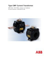
Roto-Test Switch – Design and Construction<br />
Heavy brass terminals with<br />
wire holders.<br />
Drawn copper<br />
contact blades and<br />
blade assembly.<br />
Die cast rotor flange<br />
and bearing.<br />
One piece Textolite<br />
(Bakelite) case with<br />
removable top and<br />
bottom covers.<br />
Specially designed<br />
phosphor bronze<br />
contact clips. Potential<br />
jaws are shorter than<br />
current jaws so<br />
potential contact is<br />
broken before current<br />
contact is made.<br />
Textolite rotor mounted<br />
on square steel shaft.<br />
Extra strong mounting<br />
inserts molded in case.<br />
Design & Construction Features<br />
SIMPLE AND<br />
EFFICIENT<br />
Meter Devices Roto-Test Switch is<br />
extremely simple and efficient in<br />
design and compact in<br />
construction. Mechanically and<br />
electrically, its construction is as<br />
close to perfect as humanly<br />
possible.<br />
SAVES SPACE<br />
With numerous instruments now<br />
used on a single panel, space is at<br />
a premium. The Roto-Test Switch<br />
saves space, requiring only a 4"x4"<br />
area on the board. The Roto-Test<br />
Switch can be applied to any type<br />
of switchboard for use with any<br />
standard make of instruments,<br />
meters, relays, etc.<br />
SAVES TIME IN<br />
<strong>TEST</strong>ING<br />
The Roto-Test Switch reduces<br />
testing time to a minimum. A turn<br />
of the key throws the switch into<br />
the testing position without<br />
disconnecting the instruments or<br />
meters from service. Testing is<br />
completed in as little as 60<br />
seconds. Compared to other<br />
methods, Meter Devices Roto-Test<br />
Switch operates in a fraction of the<br />
time.<br />
Operators can test many more<br />
applications per day. The number<br />
of testers required is materially<br />
reduced. Substantial savings in<br />
maintenance costs are realized.<br />
CASE<br />
One piece Textolite (Bakelite) case<br />
with removable top and bottom<br />
covers. Extra strong brass inserts<br />
and reinforcing ribs are molded<br />
into the case. Die cast rotor flange<br />
and bearing provide years of<br />
trouble free operation. Heavy brass<br />
terminals and wire holders are<br />
standard.<br />
CONTACT JAWS &<br />
BLADES<br />
The contact jaws are a Meter<br />
Devices exclusive! The doublespring,<br />
phosphor-bronze jaws are<br />
fortified with high conductivity<br />
phosphor bronze reinforcing clips.<br />
The jaw is a spring in itself and will<br />
not spread, assuring perfect<br />
contact, low resistance and no<br />
overheating.<br />
29
Meter Devices Test Switches<br />
Roto-Test Switch<br />
PHOSPHOR BRONZE<br />
CONTACT JAWS<br />
The jaw is press-formed around the<br />
head of the stud, making it rigid,<br />
permanent and impossible to<br />
detach. Spring bronze clip is<br />
inserted over all. The phosphor<br />
bronze jaw is a spring in itself and<br />
will not spread, insuring perfect<br />
contact at all times. An extra heavy<br />
stud bolt is used. The design of the<br />
contact jaws is exclusive to Meter<br />
Devices.<br />
BLADE ASSEMBLY<br />
The hinge jaw is formed around<br />
the heavy stud bolt, locking it<br />
permanently in place. The blade<br />
pivots in the jaw on a brass rivet. A<br />
Belleville spring washer secures<br />
the blade. This method of assembly<br />
provides a free turning, nonbinding<br />
joint between blade and<br />
jaws. Contact blades are made of<br />
hard-drawn copper. Contact edges<br />
are chamfered, assuring perfect<br />
contact.<br />
ROTOR AND SHAFT<br />
Rotor is unusually tough and<br />
durable, made of Textolite<br />
(Bakelite). It is mounted on a<br />
square shaft to prevent any<br />
possibility of misalignment.<br />
Contains no pins to shear off and<br />
allow rotor to turn on the shaft.<br />
Rotor is mounted meshing<br />
perfectly with the teeth of the<br />
contact blade, preventing any<br />
possibility of working out of<br />
alignment. Shaft does not extend<br />
through rear of case, since the<br />
rear hub is cast in the case.<br />
BAKELITE OVAL<br />
HANDLE<br />
BAKELITE PISTOL-<br />
GRIP HANDLE<br />
STEEL <strong>TEST</strong> KEY<br />
with interlocking pin<br />
Catalog No. Description Type of Handle<br />
30<br />
400-400 Steel, Cadmium Plated Removable<br />
400-401 Bakelite, Pistol Grip Removable<br />
400-402 Bakelite, Oval Non-removable<br />
400-405 Bakelite, Pistol Grip Non-removable<br />
400-406 Bakelite, Oval Removable
Meter Devices Test Switches<br />
ESCUTCHEON PLATE<br />
The Escutcheon Plate is of standard<br />
switchboard design and readily<br />
aligns with instrument plates of<br />
leading instrument manufacturers.<br />
Constructed of heavy pressed<br />
metal with counter-sunk holes to<br />
mount screws in a neat<br />
appearance. A slot in the plate<br />
interlocks and secures the key. It is<br />
impossible to remove the key until<br />
the switch has been restored to the<br />
operating position.<br />
5 5/8”<br />
4”<br />
END<br />
3 3/4”<br />
9/32” DIA<br />
4 HOLES<br />
1 7/8”<br />
CASE<br />
2 3/8”<br />
1 3/16”<br />
DRILLING TEMPLATE<br />
4 1/4” 6 1/4”<br />
Case is molded in one piece using<br />
Textolite (Bakelite). All-brass inserts<br />
are molded in place for optimum<br />
strength, both electrically and<br />
mechanically. Removable top and<br />
bottom dust-proof covers are<br />
interchangeable. Four-point<br />
suspension is provided for<br />
mounting with heavy brass inserts<br />
molded in position. No nuts are<br />
necessary in the switch case.<br />
4”<br />
2”<br />
2 3/8”<br />
1 3/16”<br />
7/8”<br />
MOUNTING & <strong>TEST</strong>ING<br />
The Roto-Test Switch is<br />
permanently mounted on the rear<br />
of the board by means of heavy<br />
brass inserts molded into the case.<br />
Only five holes are required.<br />
All operations and tests are made<br />
in front of the board; there is no<br />
need for the tester to go to the rear<br />
of the board.<br />
Testing is made by interlocking<br />
key. When the switch is in the<br />
"Test" position, the key cannot be<br />
removed.<br />
Thus there is no possible danger<br />
to operator or equipment since<br />
there are:<br />
No live parts exposed<br />
No wrong connections<br />
No current transformers open<br />
No trip circuits open<br />
No loose connections<br />
All hazards to which an operator<br />
or tester is exposed when testing<br />
instruments or relays at the rear of<br />
the board are entirely eliminated.<br />
3 3/4”<br />
4 AND 6 POLE 8 AND 10 POLE<br />
115º<br />
90º<br />
25º<br />
OPERATING POSITION<br />
IN.<br />
.307 +0 .003 DIA OF SHAFT<br />
31
Meter Devices Test Switches<br />
Roto-Test Switch<br />
32<br />
POTENTIAL CURRENT Approx.<br />
Meter Devices No. of Poles CONTACTS CONTACTS Shipping<br />
Catalog No.* each S.P.D.T. (Break before (Make before Weight<br />
make)<br />
break)<br />
401-404 4 0 4 5lbs.<br />
401-422 4 2 2<br />
401-440 4 4 0<br />
402-606 6 0 6 5 lbs.<br />
402-624 6 2 4<br />
402-633 6 3 3<br />
402-642 6 4 2<br />
402-660 6 6 0<br />
403-808 8 0 8 6 lbs.<br />
403-826 8 2 6<br />
403-844 8 4 4<br />
403-862 8 6 2<br />
403-880 8 8 0<br />
404-10010 10 0 10 7 lbs.<br />
404-1028 10 2 8<br />
404-1046 10 4 6<br />
404-1064 10 6 4<br />
404-1082 10 8 2<br />
404-10100 10 10 0<br />
405-12012 12 0 12 7 lbs.<br />
405-12210 12 2 10<br />
405-1248 12 4 8<br />
405-1266 12 6 6<br />
405-1284 12 8 4<br />
405-12102 12 10 2<br />
405-12120 12 12 0<br />
405-14014 14 0 14 8 lbs.<br />
405-14212 14 2 12<br />
405-14410 14 4 10<br />
405-1468 14 6 8<br />
405-1486 14 8 6<br />
405-14104 14 10 4<br />
405-14122 14 12 2<br />
405-14140 14 14 0<br />
405-16016 16 0 16 10lbs.<br />
405-16214 16 2 14<br />
405-16412 16 4 12<br />
405-16610 16 6 10<br />
405-1688 16 8 8<br />
405-16106 16 10 6<br />
405-16124 16 12 4<br />
405-16142 16 14 2<br />
405-16160 16 16 0<br />
405-18018 18 0 18 13 lbs.<br />
405-18216 18 2 16<br />
405-18414 18 4 14<br />
405-18612 18 6 12<br />
405-18810 18 8 10<br />
405-18108 18 10 8<br />
405-18126 18 12 6<br />
405-18144 18 14 4<br />
405-18162 18 16 2<br />
405-18180 18 18 0<br />
405-20020 20 0 20 15 lbs.<br />
405-20218 20 2 18<br />
405-20416 20 4 16<br />
405-20614 20 6 14<br />
405-20812 20 8 12<br />
405-201010 20 10 10<br />
405-20128 20 12 8<br />
405-20146 20 14 6<br />
405-20164 20 16 4<br />
405-20182 20 18 2<br />
405-20200 20 20 0
Meter Devices Test Switches<br />
BROOKS UTILITY PRODUCTS GROUP<br />
METER DEVICES COMPANY<br />
A Subsidiary of E.J. BROOKS Company<br />
P.O. Box 6382, Station B<br />
Canton, Ohio 44706<br />
Phone: (330) 455-0301<br />
Fax: (330) 455-1461<br />
Toll Free – 1 888 FOR-METER<br />
www.meter-devices.com<br />
E.J. BROOKS COMPANY<br />
8 Microlab Road<br />
Livingston N.J. 07039<br />
Phone: (973) 597-2900<br />
Fax: (973) 597-2919<br />
Toll Free: 1 800 458-SEAL<br />
www.ejbrooks.com<br />
EKSTROM INDUSTRIES, INC.<br />
A Subsidiary of E.J. BROOKS Company<br />
23847 Industrial Park Drive<br />
Farmington Hills, MI 48335<br />
Phone: (248) 477-0250<br />
Fax: (248) 477-2583<br />
Toll Free: 1 800 532-IDEA<br />
www.ekstrom-metering.com<br />
e-mail: marketing@ekstrom-metering.com<br />
OTHER BROOKS OPERATING UNITS<br />
In 1998, the E. J. <strong>Brooks</strong> Company celebrated its 125th<br />
anniversary. Originally staffed by a small handful of<br />
employees, our company now employs over 600<br />
people. E. J. <strong>Brooks</strong> has grown into a manufacturing<br />
enterprise with 12 operating units worldwide serving<br />
customers in more than 60 countries.<br />
E.J. BROOKS<br />
INDUSTRIES, LTD.<br />
412 High Street, East<br />
Strathroy, Ontario N7G 1H5<br />
Canada<br />
Phone: (519) 245-5369<br />
Fax: (519) 245-5352<br />
E.J. BROOKS (EUROPE)<br />
LIMITED<br />
6, The Metro Centre,<br />
Bridge Road<br />
Orpington, Kent BR5 2BE,<br />
England<br />
Phone: (0) 1689 83 63 31<br />
Fax: (0) 1689 83 62 94<br />
BROOKS SELOS DE<br />
SEGURANCA DO BRASIL<br />
LTDA.<br />
Rua Timoteo, 80 - Bairro:<br />
Santa Ines<br />
CEP: 31080-040, Belo<br />
Horizonte<br />
Minas Gerais, Brasil<br />
Phone: 31-463-1839<br />
Fax: 31-463-4724<br />
BROOKS/TODO Seguridad<br />
En Espana S.A.<br />
C/VIC No. 26-28,<br />
08120 La Llagosta<br />
Barcelona, Spain<br />
Phone: 3-560-5500<br />
Fax: 3-560-5701<br />
R A N S<br />
U A R D<br />
TRANS-GUARD<br />
INDUSTRIES, INC.<br />
903 S. Wayne<br />
P.O. Box 367<br />
Angola, Indiana 46703<br />
Phone: (219) 665-9402<br />
Fax: (219) 665-5814<br />
ZAPPA PLASTICS. INC.<br />
165 Howard Street<br />
Phillipsburg, N.J. 08865<br />
Phone: (908) 454-4500<br />
Fax: (908) 454-4507<br />
WALING TOOL & DIE<br />
COMPANY<br />
23850 Freeway Park Drive<br />
Farmington Hills, MI 48335<br />
Phone: (248) 476-6680<br />
Fax: (248) 476-7964<br />
ACROMARK INDUSTRIES<br />
60 Locust Avenue<br />
P.O. Box 236<br />
Berkeley Heights, N.J. 07922<br />
Phone: (908) 464-6474<br />
Fax: (908) 464-0673
METER DEVICES COMPANY<br />
A Subsidiary of the E. J. BROOKS Company<br />
3359 Bruening Avenue S.W.<br />
P.O. Box 6382, Station B<br />
Canton, Ohio 44706<br />
Phone: (330) 455-0301<br />
Fax: (330) 455-1461<br />
Toll Free - 1 888 FOR-METER<br />
www.meter-devices.com