Modular Lube® Lubrication Systems Divider Valves - Dean Industrial
Modular Lube® Lubrication Systems Divider Valves - Dean Industrial
Modular Lube® Lubrication Systems Divider Valves - Dean Industrial

You also want an ePaper? Increase the reach of your titles
YUMPU automatically turns print PDFs into web optimized ePapers that Google loves.
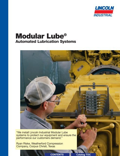
People, Capabilities and <strong>Systems</strong> toSave Money and Increase ProductivityWe’re the largest and mostsuccessful company in our fieldbecause we continually satisfy ourcustomers with the world’s bestlubrication and pumping systems.For almost 90 years, companieshave relied on our technical andquality leadership, our world-classmanufacturing and customerservice, and our vast network ofdistributors and support facilities.Lincoln <strong>Industrial</strong> develops newproducts and systems at researchand development facilities in theU.S., Germany and India thatprovide global and regionalapplication solutions.We have solutions for largeprocessing plants, automotivemanufacturing, pulp and papermills, and food and beveragefacilities. Virtually every industrialprofessional involved in operations andmaintenance can benefit from Lincoln<strong>Industrial</strong> systems.<strong>Industrial</strong>SolutionsWorldwide SupportQualityManufacturingOn the road or in the field, Lincoln <strong>Industrial</strong>protects heavy equipment used in mining,construction, agriculture and over-the-roadtrucking. The world’s leading manufacturersoffer our systems as standard equipment orfactory options.Lincoln <strong>Industrial</strong> builds precisionmetal components, state-of-the-artelectronic controls, and the industry’stop-performing pump systems.Our quality systems in the UnitedStates and Germany areISO 9001 registered.With five technical supportcenters on three continents, anda network of system houses anddistributors supported by regionalsales and service offices, ourcustomers can always draw onour worldwide resources.Customer ServiceResearch &Development BearingSaver ®To make sure your investmentresults in significant savings,Lincoln <strong>Industrial</strong> developeda unique program calledBearingSaver ® . You not only geta complete audit of your facility,you also receive an analysis ofyour return on investment.Mobile Equipment
<strong>Modular</strong> Lube ® <strong>Lubrication</strong> <strong>Systems</strong>Introduction to <strong>Modular</strong> LubeBuilt-in design optionsWhen new technology calls for design alterations, the system designer can add or delete lubrication points withoutdisturbing existing piping.It’s an economical systemLincoln <strong>Industrial</strong>’s <strong>Modular</strong> Lube single-line progressive system requires less piping and lower tubing costs atinstallation—and costs less to maintain or change when the need arises.Patented by-pass blockThis unique feature enables design engineers to extend any Lincoln <strong>Industrial</strong> <strong>Modular</strong> Lube system simply byremoving the by-pass block and replacing it with a metering valve. When new machine accessories are added,<strong>Modular</strong> Lube stands ready to service any bearing point requirements.Central SignalingIf a malfunction should occur due to a broken air line, low lubricant level, high pressure or line blockage, Lincoln<strong>Industrial</strong>’s <strong>Modular</strong> Lube automatic lube system controls can be configured to signal the operator with a visual oraudible alarm, and interlock contacts activate a machine shut-down circuit.Plug-in conceptThe Lincoln <strong>Industrial</strong> modular concept allows faster and easier changing of metering valve sizes. <strong>Modular</strong> pumps,reservoirs and timers make up a compact easy-to-mount lube system, simplifying the work of system designers andmaintenance engineers.Versatile interchangeable components<strong>Divider</strong> valves, pumps reservoirs and controls can be used to tailor a Lincoln <strong>Industrial</strong> <strong>Modular</strong> Lube system to suitindividual needs and/or requirements. Inventory costs are reduced to a minimum by purchasing modular components.You’re assured of positive stallIf a lubricating line plugs, any progressive lube system should shut down entirely - that’s what it’s designed to do.However, when a feed line becomes plugged on some systems, system pressure can cause lubrication to graduallyslip by a valve piston, allowing the system to resume functioning -- with one or more lubricating lines out of operation.Machinery bearings could run dry with disastrous results. <strong>Modular</strong> Lube has the closest piston-to-valve tolerances inthe industry, virtually assuring you a positive stall every time.UV, MM, XL SeriesDesigned for standard industrial applications. UV,MM, XL <strong>Modular</strong> Lube systems are fully automatic,centralized lubrication systems for use on all typesof industrial machinery.Type UV, MM and XL are available in several divider valvesizes and outputs, and provides maximum flexibility inapplication. This is the most versatile of the <strong>Modular</strong> Lubesystems. It can be installed on all machine tools (metalcutting,metal forming), foundry machinery, wood-workingand wood processing equipment, printing machinery,mining equipment and material handling machinery.MC SeriesDesigned for gas engine and compressor lubricationsystems. MC series systems are designed for the gastransmission industry and are available with Viton seals.The divider valves are compatible with either syntheticor petroleum-based lubricants depending upon the typeof gasket plate installed. High-pressure capability toovercome back pressure with CSA-approved monitoringcomponents available.2
<strong>Modular</strong> Lube ® <strong>Lubrication</strong> <strong>Systems</strong>Introduction to <strong>Modular</strong> Lube<strong>Modular</strong> Lube <strong>Divider</strong> <strong>Valves</strong>Lincoln <strong>Industrial</strong> divider valve assemblies are comprised of three or more metering valves mounted to a segmentedbaseplate. The metering valves are available with single or twin outlets and may be externally singled or cross-ported.Extremely close tolerances between piston and valve body allow metering valves to deliver precise volumes of lubricantat high operating pressures.414125253636414125253636Illustration 1The inlet passageway is connected to all piston chambers at all times with only one piston free to move at any onetime. With all the pistons at the far right, lubricant from the inlet flows against the right end of piston 1 (top).Illustration 2Lubricant flow shifts piston 1 from right to left, dispensing lube from outlet 1. The shifting piston 1 directs thelubricant flow against the right side of piston 2 (center).Illustration 3Lubricant flow shifts piston 2 from right to left, dispensing lube through valve ports of piston 1 and through outlet 2.The shift of piston 2 directs lubricant flow against the right side of piston 3.Illustration 4Lubricant flow shifts piston 3 (bottom) from right to left, dispensing lube through the valve ports of piston 2 andthrough outlet 3. The shift of piston 3 directs lubricant through a connecting passage to the left side of piston 1.Lubricant flow against the left side of piston 1 begins the second half-cycle, which shifts pistons from left to right,dispensing lubricant through outlets 4, 5 and 6 of the divider valve.ApplicationsLincoln <strong>Industrial</strong> <strong>Modular</strong> Lube systems are popular in metal cutting and machiningapplications and for lubricating large compressors and other equipment in theoil and gas market.Many machine makers specify that <strong>Modular</strong> Lube be installed right at their factory.Customers who have purchased machines without automatic lubrication can have<strong>Modular</strong> Lube systems retro-fitted in the field.3
<strong>Modular</strong> Lube ® <strong>Lubrication</strong> <strong>Systems</strong><strong>Divider</strong> <strong>Valves</strong>MC <strong>Divider</strong> <strong>Valves</strong>1/8" NPSF (F)LubricantOutlets1/4" NPSF (F)Lubricant InletInlet SectionIntermediateSection<strong>Divider</strong>ValveTie Rod5/16"-24 UNF (F)AlternateOutlet/IndicatorPortsEnd SectionMC <strong>Divider</strong> <strong>Valves</strong> are designed to dispense either petroleum based or synthetic lubricants in gas engine and compressorlubrication systems. Baseplate components are available with a Viton gasket plate for petroleum based or syntheticlubricants.Segmented baseplate assembly contains all inlet and outlet connections. Alternate outlet ports are located on the faceof the divider valve which may be used for installation of performance indicators.Specifications:Maximum Maximum Lube Lube Performance Material of SealLube Points/ Operating Press. Inlet Outlet Indicator Port Construction ConstructionAssembly psig / bar16 6000 / 410 ¹⁄₄" NPTF(F) ¹⁄₈" NPSF(F) ¹⁵⁄₁₆" - 24 UNF Zinc plated steel Viton* Can also be used as an alternate outlet port.MC Baseplate and Tie Rod Specifications:Maximum Number Inlet End Tie Intermediate DimensionsNumber of of <strong>Divider</strong> Section Section Rod Section (Qty) AOutlets <strong>Valves</strong> in. mm6 3 236640 87914 (3) 5.09 1298 4 236641 87914 (4) 6.00 15210 5 87912 87913 236642 87914 (5) 6.91 17612 6 236643 87914 (6) 7.81 19814 7 236644 87914 (7) 8.72 22116 8 236645 87914 (8) 9.63 245.Note: Use 68645 closure plug ( 1 ⁄8" NPT) to plug non-working outlets.MC <strong>Divider</strong> Valve Specifications:Single OutletTwin OutletModel NumberLubricantModel NumberLubricantW/RightOutputW/RightOutputDesignation Standard Side Cycle per OutletDesignation Standard Side Cycle per OutletModel Indicator* cu. in. ccIndicator* cu. in. cc06S 874061 — .012 .19606T 874062 — .006 .09809S 874091 — .018 .29509T 874092 — .009 .14712S 874121 874123 .024 .39312T 874122 874124 .012 .19718S 874181 874183 .036 .59018T 874182 874184 .018 .29524S 874241 874243 .048 .78724T 874242 874244 .024 .393* Cycle indicator pin can be moved to left side. * Cycle indicator can be moved to left side.Model 874000 MC Bypass Block Optional by-pass block permits addition or deletion of lubrication points withoutdisturbing existing installations. Includes mounting screws and Viton gasket plate.5
<strong>Modular</strong> Lube ® <strong>Lubrication</strong> <strong>Systems</strong><strong>Divider</strong> <strong>Valves</strong>MM <strong>Divider</strong> <strong>Valves</strong>MM <strong>Divider</strong> <strong>Valves</strong> are designed to meter oil or grease in automatic or manual systems installed on all types of industrialmachinery. Physically smaller than the UV series, MM divider valve assemblies are used in complete MM systems or assecondary assemblies with UV and XL divider valves.Segmented baseplate assembly contains all inlet and outlet connections. Alternate outlet ports are located on the face ofthe divider valve which may be used for installation of performance indicators.Specifications:Maximum Maximum Lube Lube Performance Material of SealLube Points/ Operating Press. Inlet Outlet Indicator Port* Construction ConstructionAssembly psig / bar16 2500 / 170 ¹⁄₈" NPTF(F) ¹⁄₈" NPTF(F) ¹⁵⁄₁₆" - 24 UNF Zinc plated steel Buna-N* Can also be used as an alternate outlet port.MM Baseplate and Tie Rod Specifications:Maximum Number Inlet End Tie Intermediate DimensionsNumber of of <strong>Divider</strong> Section Section Rod Section AOutlets <strong>Valves</strong>* (Qty. rq’d.) (Qty. rq’d.) (Qty. rq’d.) (Qty. rq’d.) in. mm6 3 236646 (3) 87907 (3) 4.47 1148 4 236647 (3) 87907 (4) 5.25 13310 5 87906 (1) 87908 (1) 236648 (3) 87907 (5) 6.03 15312 6 236649 (3) 87907 (6) 6.81 17314 7 236650 (3) 87907 (7) 7.59 19316 8 236651 (3) 87907 (8) 8.38 213* Use No. 68645 closure plug (¹⁄₈" NPT) to plug non-working outlets.MM <strong>Divider</strong> Valve Specifications:Single OutletCycle Indicator Model LubricantStandardOutput perDesignation Model Left Right Outletcu. in. cc5S 871051 — — .010 .16410S 871101 — — .020 .32815S 871151 871155 871153 .030 .492Twin OutletCycle Indicator ModelLubricantOutput perDesignation Basic Model Left Right Outletcu. in. cc5T 871052 — — .005 .08210T 871102 — — .010 .16415T 871152 871156 871154 .015 .246Model 871000 Bypass Block Optional by-pass block permits addition or deletion of lubrication points withoutdisturbing existing installations. Includes mounting screws and Buna-N Gasket plate.6
<strong>Modular</strong> Lube ® <strong>Lubrication</strong> <strong>Systems</strong><strong>Divider</strong> <strong>Valves</strong>XL <strong>Divider</strong> <strong>Valves</strong>XL <strong>Divider</strong> <strong>Valves</strong> are designed to meter large volumes of oil or grease in manual or automatic lubrication systems for alltypes of industrial machinery. These units can be used in complete XL systems or integrated as a primary divider valveassembly in systems using UV or MM divider valves as secondaries.Solid one piece baseplate contains all inlet and outlet connections. Convenient front located ports on the divider valveare provided for installation of any desired performance indicators.Specifications:Maximum Maximum Lube Lube Performance Material of SealLube Points/ Operating Press. Inlet Outlet Indicator Port* Construction ConstructionAssembly psig / bar16 2500 / 172 ³⁄₈" NPTF(F) ¹⁄₄" NPTF(F) ¹⁄₈" NPTF(F) Zinc plated steel Buna-N* Can also be used as an alternate outlet port.XL Baseplate Specifications:Maximum No. DimensionsModel Number of of <strong>Divider</strong> ANo. Outlets <strong>Valves</strong>* in. mm87030-3 6 3 5.34 13687030-4 8 4 6.69 17087030-6 12 6 9.38 238* Use No. 67359 closure plug (¹⁄₄" NPT) to plug non-working outlets.XL <strong>Divider</strong> Valve Specifications:Single OutletTotalStandard With Right LubricantDesignation Model Side Cycle OutputIndicator cu. in. cc30S 87026-03S — .060 .98350S 87026-05S — .100 1.6480S 87026-08S — .160 2.62100S 87026-10S — .200 3.28120S 87026-12S 87066-12S .240 3.93150S 87026-15S 87066-15S .300 4.92Twin OutletTotalStandard With Right LubricantDesignation Model Side Cycle OutputIndicator cu. in. cc30T 87026-03T — .030 .49250T 87026-05T — .050 .82080T 87026-08T — .080 1.31100T 87026-10T — .100 1.64120T 87026-12T 87066-12T .120 1.97150T 87026-15T 87066-15T .150 2.46Model 87028 XL Bypass Block Optional by-pass block permits addition or deletion of lubrication points withoutdisturbing existing installations. Includes mounting screws and Buna-N O-ring seals.7
<strong>Modular</strong> Lube ® <strong>Lubrication</strong> <strong>Systems</strong>UV, XL <strong>Divider</strong> Valve AccessoriesPin Type Performance IndicatorsHigh pressure ruptures internal disc and extends indicator.PressureReplacementUV, XLRatingDiscDisc ModelModel psig barColor(10/pkg)87930 1450 99 Yellow 69813-1087931 1750 119 Red 69813-1287932 2650 180 Pink 25031187933 3250 221 Purple 250312Note: O-rings are VitonConnector¹⁄₈" NPTF(M)Atmospheric Type Performance IndicatorsHigh pressure ruptures disc, pressure and lubricant vents to the atmosphere.PressureReplacementUV, XLRatingDiscDisc ModelModel psig barColor(10/pkg)87934 1450 99 Yellow 69813-1087935 1750 119 Red 69813-1287936 3250 221 Purple 25031287937 3700 252 Yel/Nat 250313Reset Type Performance IndicatorsUV, XL ModelNote: O-rings are VitonPressure RatingConnector¹⁄₈" NPTF(M)High pressure extends indicator. Reset the indicator after pressure is relieved.AdapterpsigbarConnector87938 500 3487939 1000 6887940 1500 102 ¹⁄₈" NPTF(M)87941 2000 13687942 3000 204Adapter connects UV, XL style performance indicators to MC, MM style dividervalves and old style ML. Includes Viton o-ring.ModelThreads87915 ⁵⁄₁₆" -24 Male x ¹⁄₈" NPTF(F)8
<strong>Modular</strong> Lube ® <strong>Lubrication</strong> <strong>Systems</strong>MC, MM <strong>Divider</strong> Valve AccessoriesPin Type Performance IndicatorsHigh pressure ruptures internal disc and extends indicator.MM, MCModelPressureReplacementRatingDiscDisc Modelpsig barColor(10/pkg)Connector87895 1450 100 Yellow 69813-1087896 1750 120 Red 69813-1287897 2050 140 Orange 69813-14 ⁵⁄₁₆"-24 Male87898 2350 160 Aluminum 69813-1687899 3250 220 Purple 69813-22Note: O-rings are VitonAtmospheric Type Performance IndicatorsHigh pressure ruptures disc, pressure and lubricant vents to the atmosphere.MM, MCModelPressureReplacementRatingDiscDisc Modelpsig barColor(10/pkg)87890 1450 100 Yellow 69813-1087891 2050 140 Orange 69813-1487892 3250 220 Purple 69813-2287893 3700 250 Yellow 69813-10Reset Type Performance IndicatorsModelpsigPressure RatingSpring/TagColor87885 1000 70 Green87886 1500 100 Yellow87887 2000 135 Red87888 2500 170 Orange87889 3000 200 BlueNote: O-rings are VitonbarConnector⁵⁄₁₆"-24 MaleHigh pressure extends indicator. Reset the indicator after pressure is relieved.AdapterModelThreads87915 ⁵⁄₁₆" -24 Male x ¹⁄₈" NPTF(F)Connector⁵⁄₁₆"-24 MaleAdapter connects UV, XL style performance indicators to MC, MM style dividervalves and old style ML. Includes Viton o-ring.9
<strong>Modular</strong> Lube ® <strong>Lubrication</strong> <strong>Systems</strong><strong>Divider</strong> Valve AccessoriesCycle SwitchCycle Switch attaches to valve with cycle indicator pin, sends electrical signal tocontroller.Model87070 SPDTCycle CounterModelSwitch Switch ConduitType Capacity Connector15 Amps @ 125/250 VAC0.5 Amps @ 125 VDCMaximum Counts87828 99,999¹⁄₂" - 14 NPSMCycle Counter attaches to valve with cycle indicator pin, counts and records cycles.Proximity SwitchProximity Switch is a magnetic reed switch that attaches to divider valve for use inhazardous environments.ModelBlockStyleSwitch Switch CSAType Capacity CertificationConduitConnector85617 UV87617 MC10 Watts Class I, Group A, B, C & DSPST 200 VDC Class II, Group E, F & G ¹⁄₂" NPT(F)87618 XL Size03 thru120.5 Amp Hazardous LocationsExternal Singling/Cross Port KitExternal Cross Port Kit connects alternate outlet ports to combine the volume oftwo divider valves through a single outlet.Model Block Type Application/Usage87943 UV Crossport87905 MC Single and Crossport87903 MM Single and Crossport87824 XL SinglingBalancing ValveModel 87865 Balancing Valve is used when back pressure differential betweendivider valve outlets exceeds 1000 psi (68 bar).Pressure AdjustmentModel Min Maxpsig bar psig barInlet/OutletSealMaterial87865 250 17 6000 408 ¹⁄₈" NPTF(F) VitonMounting BracketModel 250286 (UV) and Model 360675 (MC, MM) Mounting Brackets—mount divider valve assembly off the face of vertical surfaces. Use two bracketsper divider valve assembly.10
<strong>Modular</strong> Lube ® <strong>Lubrication</strong> <strong>Systems</strong><strong>Divider</strong> Valve AccessoriesCheck valves maintain prime in feed lines and check back pressure frompressurized lubrication points.Double Ball, StraightPressureHex Hex Hex LengthModelInlet OutletMax Opening Material Inlet-in. Outlet-in. in./mm880511 8000 145 ¹⁄₄" ¹⁄₄" Carbon Steel 3.72/94.5880518-9 psig psig NPTF(F) NPTF(M) 316 S.S. 3.75/95.3880517 550 10 ¹⁄₈" ¹⁄₈" Carbon Steel 13 /16"3.31880519-9 bar bar NPTF(F) NPTF(M) 316 S.S. 3 84.1/4"5000 80psig psig 9/16-18 7/16-20 Stainless3 /4"880015-9UNF UNF Steel2.75/70340 6bar barBall & Poppet, StraightModel880513880514PressureHex Hex Hex LengthInlet OutletMax Opening Material Inlet-in. Outlet-in. in. / mm2000 50 ¹⁄₈" ¹⁄₈" 2.75psig psig NPTF(F) NPTF(M) Carbon 3 70.0/4"13 /16"140 3.5 ¹⁄₄" ¹⁄₄" Steel 3.06bar bar NPTF(F) NPTF(M) 77.7Ball Type, StraightPressureHex Hex LengthModelInlet OutletMax Opening Material in. in. / mm87817 7500 psig 20-70 psig ¹⁄₄" NPTF(M) ¹⁄₄" NPSF(F)11 /16" 1.38/35.1Carbon87818 500 bar 1.5-5 bar ¹⁄₈" NPTF(M) ¹⁄₈" NPTF(F) 9 /16" 1.19/30.2Steel6000 psig 31-70 psig130021-3400 bar 2-5 bar¹⁄₈" NPTF(F) ¹⁄₈" NPTF(M)1 /2" 1.06/27.0Ball & Poppet, 90°ModelPressureHex Hex DimensionsHexInlet Outlet Inlet Outlet in. / mmMax Opening Materialin. in. A B8805152000psig 50 psig ¹⁄₈" ¹⁄₈" Carbon 3.38 1.25140 bar 3.5 bar NPTF(F) NPTF(M) Steel /4"/16"86 31.811
<strong>Modular</strong> Lube ® <strong>Lubrication</strong> <strong>Systems</strong>Installation ComponentsLubricant flows through Supply Lines between the pump and divider valves, then through Feed Lines between thedivider valve and the bearing. Tubing and/or pipe sizes are determined after considering both the length of the line andthe specific lubricant intended for use in the system.Your Lincoln <strong>Industrial</strong> representative can assist you in the proper selection of supply and feed line material to optimizeyour application.Listed below is a simplified outline of the installation components offered. For a complete listing of products, pleaserefer to the Installation Components catalog.TUBINGHydraulic, Steel, Stainless Steeland NylonSingle and Multiple TubeClampsHeavy Duty, Standard Duty,Threaded Sleeve and Snap-OnCoupler Tube FittingsQuicklinc ® Tubing AdapterZerk-Lock Grease FittingAdaptersPIPINGNon-MetallicSeamlessContinuous WeldedForged FittingsMalleable Iron Fittings316 Stainless Steel Pipeand FittingsStainless Steel FittingsGalvanized Pipe, Threaded Plugand FittingsACCESSORIESSupply, Feed and Bulk FeedLine HoseAir HoseKits for Hose RepairHeavy-Duty Air Line QuickDisconnectsAIR CONTROLAND ACCESSORIESManual Shut-Off <strong>Valves</strong>Pressure GaugesLubricant Filters and StrainersAIRCARE AIRPREPARATION SYSTEMS<strong>Modular</strong> Air Line Filters,Regulators and LubricatorsIntegrated/<strong>Modular</strong>Filter/Regulator with Gauge<strong>Modular</strong> Air LineCombination UnitsHigh Capacity Air Line Filters,Regulators and LubricatorsHigh Capacity Air LineCombination UnitsMiniature Air LineComponents—Air Line Filter,Regulator and LubricatorMiniature Air LineCombination Units<strong>Modular</strong> Air Line EquipmentAccessories:Lockout Valve, Quick Clamp,Quick Clamp Wall MountingBracket, Porting Block, QuickMount Pipe Adaptors, ManifoldBlock, Pressure Switch, PanelNut, Wall Mount Bracket,Tamper Resistant Cover& Seal WireAir Line Equipment Accessories:Wall Mount Bracket, HighCapacity; Mounting Bracketand Nut, Miniature; PressureGaugesPIPE FITTINGSReducing BushingsNipplesCouplingsReducing CouplingsStreet EllsTeesCrossesAdapter UnionsElbowsPipe Fitting AdaptersSupply Line SwivelsFeed Line SwivelsAnchor and Junction Blocks12
<strong>Modular</strong> Lube ® <strong>Lubrication</strong> <strong>Systems</strong>Introduction to Pumps<strong>Modular</strong> PumpsLincoln <strong>Industrial</strong>’s modular pumps are designed to efficiently supply either greaseor oil in automatic systems using divider valve metering devices. Air, hydraulic andmechanically operated units are available. These units are then matched with anappropriate intermediate baseplate, and an appropriate reservoir to make up apump assembly.If required, the reservoir can be remote mounted for ease of filling, utilizing amachine mounted baseplate and pump.Baseplates contain all of the inlet and outlet connections for the pump and lubesystem. Intermediate baseplates mounted between the pump and reservoir allowfor quick pump removal without disturbing any existing piping. Removal of thepump does not require draining of the reservoir due to an integral check-valvein the baseplate.All modular reservoirs are compatible with all pumps, offering extreme flexibility insystem design.13
<strong>Modular</strong> Lube ® <strong>Lubrication</strong> <strong>Systems</strong>Air Operated <strong>Modular</strong> PumpsModel 87200Model: 87200Ratio: 25:1Displacement: Min. .025 cu. in. .410 ccMax. .100 cu. in. 1.639 ccAir Pressure: Min. 65 psig 4.5 barMax. 150 psig 10 barDimensions (HxWxL): 2.75" x 9.88"x 2.75" 69.8 x 250.9 x 69.8 mmCylinder Type:Single acting, spring returnAir Valve Requirement:3-WayModel 87216Model: 87216Ratio: 50:1Displacement: Min. .010 cu. in. .164 ccMax. .050 cu. in. .820 ccAir Pressure: Min. 35 psig 2.5 barMax. 150 psig 10 barDimensions (HxWxL): 2.75" x 9.88"x 2.75" 69.8 x 250.9 x 69.8 mmCylinder Type:Single acting, spring returnAir Valve Requirement:3-WayModel 130280Model: 130280Ratio: 25:1Displacement: Min. .025 cu. in. .410 ccMax. .100 cu. in. 1.639 ccAir Pressure: Min. 65 psig 4.5 barMax. 150 psig 10 barDimensions (HxWxL): 2.75" x 9.88"x 2.75" 69.8 x 251 x 69.8 mmCylinder Type:Double actingAir Valve Requirement:4-WayModel 130179Model: 130179Ratio: 25:1Displacement: Min. .25 cu. in. 1.0 ccMax. 1.0 cu. in. 16.39 ccAir Pressure: Min. 65 psig 4.5 barMax. 150 psig 10 barDimensions (HxWxL): 5.50" x 15.38"x 4.50" 139.7 x 290.6 x 114.3 mmCylinder Type:Single acting, spring returnAir Valve Requirement:3-WayNotes:Model 87200, 87216, 130280 pumps do not have valved pistons. Use <strong>Modular</strong> Lube reservoirs only.Model 130179 pump with valved piston uses <strong>Modular</strong> Lube reservoir or pressurized(max. 2000 psig/140 bar) lube supply.All pumps include Viton o-rings for standard or synthetic lubricant.14
<strong>Modular</strong> Lube ® <strong>Lubrication</strong> <strong>Systems</strong>Mechanically Operated <strong>Modular</strong> PumpsModel 87235Model: 87235Displacement: Min. .020 cu. in. .328 ccMax. .050 cu. in. .820 ccActuator Type:RollerNote:For 87235, an approx. force of 110 lbs. is required to generate 1,000 PSI lube pressure.Model 87243Model: 87243Displacement: Min. .005 cu. in. .082 ccMax. .015 cu. in. .246 ccActuator Type:ArmNote:For 87243, a 4" height on the rod w/6 lbs. of force will generate approx. 1,000 PSI lube pressure.Hydraulic Operated <strong>Modular</strong> PumpsModel 87202Model: 87202Ratio: 7:1Displacement: Min. .025 cu. in. .100 ccMax. .10 cu. in. 1.639 ccHydraulic Pressure: Min. 275 psig 20 barMax. 2000 psig 138 barDimensions (HxWxL): 2.13" x 9.50"x 1.88" 54.1 x 241.3 x 47.7 mmCylinder Type:Double actingDirectional Valve Requirement: 4-WayModel 87220Model: 87220Ratio: 6:1Displacement: Min. .025 cu. in. .100 ccMax. .10 cu. in. 1.639 ccHydraulic Pressure: Min. 275 psig 20 barMax. 2000 psig 138 barDimensions (HxWxL): 2.13" x 11.75"x 1.88" 54.1 x 298.5 x 47.7 mmCylinder Type:Single acting, spring returnDirectional Valve Requirement: 3-WayNotes:Pumps include Viton o-rings for standard or synthetic lubricants.Pumps do not have valved pistons. Use <strong>Modular</strong> Lube reservoirs only.15
<strong>Modular</strong> Lube ® <strong>Lubrication</strong> <strong>Systems</strong>Baseplates & Reservoirs<strong>Modular</strong> Pump BaseplatesMount pump directly to a modular reservoir with intermediate baseplate.Use machine mounted baseplates with remote reservoirs.Use with Air/ Lube Lube Dimensions - in. / mm Atmos.Model Descrip. Pump Hydraulic Inlet OutletHeight Width Depth IndicatorModel Inlet psi / bar872188720487234Inter- 87200, 87202, ¹⁄₈"3.25 3.25mediate 87216, 87220, NPTF(F)—82.6 82.6130280 ¹⁄₄" 3.19 4.69 1.00NPTF(F) ¹⁄₄" 78.7 119.1 25.4 1450Machine 87235,³⁄₈" NPTF(F) 3.00 3.25 99Mount 87243 N/A NPTF(F) 76.2 82.6130095 130179¹⁄₄" 4.00 4.50 150NPTF(F) 101.6 114.3 38.1Note:Baseplates include Viton o-rings for standard or synthetic lubricants.<strong>Modular</strong> Reservoirs for Oil <strong>Systems</strong>Type Capacity Dimensions - in. / mmModel Style Outlet Gal. Liter cu. in. cc Material Height Width Depth87400 .625 2.4 144 235015.69 6.00 5.31399 152.6 135.087413Cylin- ¹⁄₂"17.69drical NPTF(F)1.25 4.7 289 4750Acrylic 450 7.31 7.4787414 1.875 7.1 433 710025.19 186.0 189.7640.887417 5 18.9 1155 1890017.50 12.56445.2 319.087418Tank ³⁄₈"10.12 13.50 11.56NPTF(F) 3 11.3 693 11350 Steel 257.4 343.4 294.187419 1.5 5.7 346 567510.50 7.56267.1 192.3Note:All reservoirs will accept 87218 Intermediate Baseplates.<strong>Modular</strong> Reservoirs for Grease <strong>Systems</strong>CapacityDimensions - in. / mmModel lbs. Kg. cu. in. cc Material Height Width Depth87406 10 4.54 300 490017.69 7.31 7.47450 186.0 189.787407 5 2.27 150 2450Acrylic 15.69 6 5.94399 152.6 150.987416 15 6.82 450 735025.19 7.47640.8 189.717.69 7.3187421* 10 4.54 300 4900450 186.0 7.41Steel25.19 188.287423* 15 6.82 450 7350640.8* Includes visual level indicator rod.Note:All reservoirs accept Model 87218 Intermediate Baseplates. Reservoirs include standard ¹⁄₂" NPTF(F) outlet.16
<strong>Modular</strong> Lube ® <strong>Lubrication</strong> <strong>Systems</strong><strong>Modular</strong> Pump AccessoriesLow-Level SwitchesLow level switches for modular design reservoirs.Model Use with Reservoir # Switch Type Electrical Rating84235 87417, 87418, 8741984250 84700 SPDT7 Amps125/250 VAC84251 8741384252 8741484466 87420, 87421, 8742315 Amps87852 874102, 87403, 87406, 87407, 87416 SPDT125/250 VAC87881 87417, 87418, 87419Low-Level Switch Assembly Kits for pneumatic and electric reciprocating pumpswith self-contained reservoirs.Model Use with Pump Model Switch Type Electrical Rating83671 87240, 87228 15 Amps; 125, 250, 480 VAC83696 87239SPDT.5 Amp 125 VDC.25 Amp 250 VDCHigh Pressure SwitchHigh pressure switch signals blockage and returns pump output to reservoir.Model Pressure Rating - psig / bar Switch Type Electrical Rating87851 1450 / 99 SPDT 15 Amps, 125/250 VAC17
<strong>Modular</strong> Lube ® <strong>Lubrication</strong> <strong>Systems</strong><strong>Modular</strong> LP PumpsModel 87212Model: 87212Type:HydraulicRatio: 5:1Hydraulic Pressure: Min. 200 psi 14 barMax. 1000 psi 68 barLubricant Output/Cycle: Min. .010 cu. in. .164 ccMax. .060 cu. in. .983 ccCylinder Type:Double actingDirectional Valve Requirements: 4-WayModel 87214Model: 87214Type:AirRatio: 18:1Air Pressure: Min. 60 psi 4 barMax. 200 psi 14 barLubricant Output/Cycle: Min. .010 cu. in. .164 ccMax. .060 cu. in. .983 ccCylinder Type:Single actingDirectional Valve Requirements: 3-WayNote:Pumps include Buna-N o-rings.<strong>Modular</strong> LP Style ReservoirsMount directly to LP pumps. Includes 3000 psig (200 bar) gauge and 900 psig(60 bar) atmospheric indicator. Transparent, polycarbonate construction.Lubricant Capacity Air Lube Dimensions - in. / mmModelType lb/pint kg liter cu. in. cc Hydraulic Outlet Height Width Depth87402 3 lb 1.36 — 90 1475 13.375Grease874035 lb 2.27 — 150 2450 ¹⁄₈" ¹⁄₈" 340.0 6.78 7.06874043 pint — 1.42 86 1420 NPSM(F) NPSM(F) 10.312 172.2 179.6Oil87405 5 pint — 2.36 144 2365 262.318
<strong>Modular</strong> Lube ® <strong>Lubrication</strong> <strong>Systems</strong>Reciprocating PumpsModel 87240 Air-Operated Reciprocating PumpModel: 87240Lubricant Type:GreaseLubricant/Air Ratio: 40:1Output/Min. @ 100 psig Air: 12 cu. in. 197 ccReservoir Capacity:* 12 lbs. 5.45 kg360 cu. in. 5900 ccAir Inlet:¹⁄₈" NPTF(F)Lube Outlet:¹⁄₄" NPTF(F)Dimensions (HxWxD): 20.5" x 9" x 16.25" 521.3 x 229 x 413 mm* Transparent Acrylic ReservoirModel 87239 Air-Operated Reciprocating PumpModel: 87239Lubricant Type:OilLubricant/Air Ratio: 40:1Output/Min. @ 100 psig Air: 12 cu. in. 197 ccReservoir Capacity: * 15 pints 7.1 liter433 cu. in. 7100 ccAir Inlet:¹⁄₈" NPTF(F)Lube Outlet:¹⁄₄" NPTF(F)Dimensions (HxWxD): 20.5" x 9" x 16.25" 521.3 x 229 x 413 mm* Transparent Acrylic ReservoirNote:Both models require a 3-way air valve.Atmospheric Indicator Pressure:Model 87240—2650 psi/180 barModel 87239—1450 psi/98 barModel 87228 Electric-Operated Reciprocating PumpModel: 87228Lubricant Type:GreaseElectrical Requirement: 220/440, 60 Hz 3 phOutput/Minute: 18 cu. in. 295 ccReservoir Capacity: * 12 lbs 5.45 kg360 cu. in. 5900 ccLube Outlet:¹⁄₄" NPTF(F)Dimensions (HxWxD): 25.38" x 9.94" x 18.06" 645 x 253 x 459 mmRelief Valve: 3700 psig 238 bar* Transparent Acrylic Reservoir19
<strong>Modular</strong> Lube ® <strong>Lubrication</strong> <strong>Systems</strong>MCLP PumpsMCLP PumpsFor natural gas engine/compressor lubrication systems.Model 130201BCCMCLP Pump complete with pump heads.Model:130201BCCType Drive:RotaryShaft Description:Left hand end, long shaftGear Ratio: 2:1Decimal Gear Ratio: .5Cam:Single lobePump Heads: (Model 130335) 10 mm (2 each)Performance Indicator: 7300 psig 500 barModel 130200DEEMCLP Pumps without pump heads.Model:130200DEEType Drive:RotaryShaft Description:Left hand endGear Ratio: 4:1Decimal Gear Ratio: .250Cam:Single lobePump Heads (Max of 2): Order separatelyPerformance Indicator: Dependent on pump headModel 130200GEEModel:130200GEEType Drive:RotaryShaft Description:Left hand endGear Ratio: 8:1Decimal Gear Ratio: .125Cam:Single lobePump Heads (Max of 2): Order separatelyPerformance Indicator: Dependent on pump headModel 130200KEEModel:130200KEEType Drive:RotaryShaft Description:Left hand endGear Ratio: 21.5:1Decimal Gear Ratio: .047Cam:Single lobePump Heads (Max of 2): Order separatelyPerformance Indicator: Dependent on pump head20
<strong>Modular</strong> Lube ® <strong>Lubrication</strong> <strong>Systems</strong>MCLP PumpsModel 130253KEEModel:130253KEEType Drive:RotaryShaft Description:Right hand end, long shaftGear Ratio: 21.5:1Decimal Gear Ratio: .047Cam:Single lobePump Heads (Max of 2): Order separatelyPerformance Indicator: Dependent on pump headModel 130300GEEModel:130300GEEType Drive:RotaryShaft Description:Right hand endGear Ratio: 8:1Decimal Gear Ratio: .125Cam:Single lobePump Heads (Max of 2): Order separatelyPerformance Indicator: Dependent on pump headModel 130300KEEModel:130300KEEType Drive:RotaryShaft Description:Right hand endGear Ratio: 21.5:1Decimal Gear Ratio: .047Cam:Single lobePump Heads (Max of 2): Order separatelyPerformance Indicator: Dependent on pump headModel 130150LEEModel:130150LEEType Drive:RatchetShaft Description:Right hand end, clockwise rotationGear Ratio: 1:2Decimal Gear Ratio: 2Cam:Single lobePump Heads (Max of 2): Order separatelyPerformance Indicator: Dependent on pump headModel 130500GEEModel:130500GEEType Drive:Right angle rotaryShaft Description:Left hand end, long shaftGear Ratio: 8:1Decimal Gear Ratio: .125Cam:Single lobePump Heads (Max of 2): Order separatelyPerformance Indicator: Dependent on pump headNotes:1. Recommended camshaft speed (RPM) for all pumps is: 12 to 75 rpm.2. MCLP output (per pump) = Input speed x decimal ratio x pump output factor* = pints per day* See MCLP pump head chart for pump output factor21
<strong>Modular</strong> Lube ® <strong>Lubrication</strong> <strong>Systems</strong>Pump AccessoriesMCLP Pump HeadsModelMax. Pump Output Max.Piston Working Factor Inlet Pump Pump PerformanceDiameter Pressure Pressure Inlet Outlet Indicatorpsig/bar Min 1 Turn Max 5 Turns psig/bar psi/bar130332 7mm 8000/544 .197 .852 50 ³⁄₈" ¹⁄₄" 5500/374130335 10mm 3500/238 .213 1.491 3.4 NPTF(F) NPTF(F) 3250/221Flow RestrictorFlow restrictor for LP Pumps with high air or hydraulic supply pressure.For Pressure Exceeding - psig / barModel Pneumatic Hydraulic Connections15104 100 / 6.8 500 / 34 ¹⁄₈" NPTF(F) x ¹⁄₈" NPTF(M)MCLP Pump Inlet FiltersPump HeadsFilterMax. Inlet PressureModelInletServed Size psig / bar130067 210 Micron 1" NPTF(F) 50 / 3.4130078 1Filler PumpManual pump for system purging and troubleshooting.ModelMax. Pressure Gauge Reading Reservoir Outletpsig / bar Capacity Adapters130117 3000 / 204 16 oz.⁵⁄₁₆" - 24 UNF(M), ⁷⁄₁₆" - 20 UNF(M),¹⁄₈" NPTF(M), ¹⁄₄" NPTF(M)No-Flow <strong>Valves</strong>MCL pump no-flow valves shut down engine or signal fault if oil flow is interrupted.Max. Oil Inlet/OutletModel Signal Operating Viscosity Air Electrical 3rd PartyType Pressure RangeSupply Rating ApprovalsAir Oilpsig / bar87862 Pneum.87601 Electric6000 60 SSU- ¹⁄₈" ¹⁄₄"408 3000 SSU NPTF(F) NPTF(F)150 psi max — —1 amp, 115 VAC CSA Class I, Group D— .5 amp, 32 VDC Class II,Group E, F & GNotes:1. Minimum flow rate .060 cu. in./minute with time delay setting of 90 seconds.2. Includes Viton oil seals.22
<strong>Modular</strong> Lube ® <strong>Lubrication</strong> <strong>Systems</strong>Pump AccessoriesFlow MeterFlow meter measures and records oil flow to the system.Model Register Oil Inlet/OutletMax. Pressure Ratingpsig / bar87806 200 counts per pint ¹⁄₄" NPTF(F) 6000 / 408MCLP Cycle MonitorsMCLP Cycle Monitors monitor and record oil flow volume delivered to lube pointsand signal fault if flow stops or diminishes significantly.Max.System(s) Electrical Power Display Alarm Time 3rd PartyModelMonitored Requirements Record Approvalspints Min. Max.87610 1 115 VAC, 50-60 Hz37.5 10 CSA Class I, Group D999,99987611 2 24 VDC Sec. Min. Class II, Group E, F & G23
<strong>Modular</strong> Lube ® <strong>Lubrication</strong> <strong>Systems</strong>Pump to Point LubricatorsModel 55i Lubricator PumpUniversal lubricator pump fits most major manufacturers’ lubricator boxes. Onepiece pump body eliminates leak points.PistonMax. Operating Max. Oil Max. OutputModel Type Dia. Inlet Sight Pressure Viscosity Per Strokein. / mm Glass psi / bar (SUS) Drops (in 3 / cc)880550 Vacuum ¹⁄₄" / 6.4 Suction 6000 / 400 9 (.0184 / .302)880560 Feed ³⁄₈" / 9.5 Tube 3500 / 240 21 (.0415 / .680)880551 Press. ¹⁄₄" / 6.4 Yes 6000 / 400 8000 9 (.0184 / .302)Inlet ¹⁄₈" 540880561 (Manifold) ³⁄₈" / 9.5 NPTM 3500 / 240 21 (.0415 / .680)Feed880552DirectFeed¹⁄₄" / 6.4¹⁄₈"NPTFNo 6000 / 400 9 (.0184 / .302)Notes: Standard Viton seals.Sight glass is Polysulfone – check for compatability with synthetic oils.End Rotary Drive LubricatorsInternal Gear and RatchetDrive Data: Type—End rotary with internal gear and ratchet. 37.5:1 ratio.Rotation— Either clockwise or counterclockwise.Power Source—Machine drive; not recommended for motor drive.Maximum Input Speed 700 RPM.Note: Number following dash in the part number indicates quantity of pumpsincluded.ModelReservoir Max. No. Drive Service SheetCapacity of Pumps Location Number800037-1,2,3,4 4 pint / 1.9L 5 RH M2-26800028-3,4 4 pint / 1.9L 5 LH M2-43800131-5 8 Pint / 3.8L 7 RH M2-25800019-5 8 Pint / 3.8L 7 LH M2-40*800015-3 4 Pint / 1.9L 4 RH M2-6*800051-5 8 Pint / 3.8L 6 RH M2-7Model800037-1,2,3,4800028-3,4800131-5800019-5Dimensions—in. / mmShaftA B C D E Dia.5¹⁄₂ / 140 10⁵⁄₈ / 2703 / 76 6⁹⁄₁₆ / 167 10³⁄₈ / 2648³⁄₄ / 222 14¹⁄₈ / 359 ⁵⁄₈ / 16*800015-312⁷⁄₁₆ / 316NA*800051-5 15¹⁵⁄₁₆ / 405* Special drive shaft and direct compressor mount.11³⁄₁₆ / 284 NA 10¹⁄₈ / 25724
<strong>Modular</strong> Lube ® <strong>Lubrication</strong> <strong>Systems</strong>Pump to Point LubricatorsEnd Rotary Drive LubricatorsSpur GearDrive Data: Type—End rotary with spur gear. 112.5:1 ratio.Rotation— Either clockwise or counterclockwise.Power Source—Machine drive; not recommended for motor drive.Note: Number following dash in the part number indicates quantity of pumpsincluded.ModelReservoir Max. No. Drive Service SheetCapacity of Pumps Location Number800066-2,3 4 pint / 1.9L 5 RH M2-20800143-3,4 4 pint / 1.9L 5 LH M2-136800289-4,5,6 8 Pint / 3.8L 7 RH M3-21ModelDimensions—in. / mmShaftA B C D E Dia.800066-2,35¹⁄₂ / 140 10⁵⁄₈ / 270800143-3,4 4 / 102 6⁹⁄₁₆ / 167 10³⁄₄ / 273 ⁵⁄₈ / 16800289-4,5,6 8³⁄₄ / 222 14¹⁄₈ / 359Internal Ratchet Drive LubricatorsDrive Data: Type—Internal 75 tooth ratchet gear.Rotation—See chart for power stroke direction.Power Source—Machine drive.Note: Number following dash in the part number indicates quantity of pumpsincluded.ModelReservoir Max. No. Drive Power Service SheetCapacity of Pumps Location Stroke Number800065-1 2 pint / .95L 2 LH CW M3-31800376-2 3 pint / 1.4L 3 RH CW M3-31800118-2,3 4 Pint / 1.9L 5 RH CW M2-164800100-2 4 Pint / 1.9L 5 LH CW M3-31800031-3,5 8 Pint / 3.8L 5 RH CW M3-31Oscillating Drive 120° Stroke800070-3 4 Pint / 1.9L 5 RH CCW M2-116ModelDimensions—in. / mmShaftA B C D E Dia.800065-1 3³⁄₄ / 95 5³⁄₈ / 137 10¹⁄₂ / 269800376-2 5¹⁄₂ / 140 7¹⁄₈ / 181 10³⁄₄ / 273800118-2,3 5¹⁄₂ / 140 10⁵⁄₈ / 270 3 / 76 6⁹⁄₁₆ / 167 10³⁄₈ / 264 ⁵⁄₈ / 16800100-2 5¹⁄₂ / 140 10⁵⁄₈ / 270 10³⁄₄ / 273800031-3,5 8³⁄₄ / 222 14¹⁄₈ / 359 10³⁄₄ / 273Oscillating Drive 120° Stroke800070-3 5¹⁄₂ / 140 10⁵⁄₈ / 270 5¹⁄₄ / 133 6⁹⁄₁₆ / 167 10³⁄₈ / 264 ⁵⁄₈ / 1625
<strong>Modular</strong> Lube ® <strong>Lubrication</strong> <strong>Systems</strong>Pump to Point LubricatorsRight Hand Bottom Vertical Drive LubricatorsFilter DriveNote: Number following dash in the part number indicates quantity of pumpsincluded.Model Reservoir Max. No. Ratio Service SheetCapacity of Pumps Number800192-3 4 pint / 1.9L 3M2-3730:1800090-4 8 pint / 3.8L 4 M2-179ModelDimensions—in. / mShaftA B C D Dia.800192-3 9³⁄₄ / 248 2 / 51800090-4 13³⁄₈ / 340 2¹⁄₂ / 63.55 / 127 10³⁄₄ / 273 ¹⁄₂ / 13Rear Rotary Drive LubricatorsNote: Number following dash in the part number indicates quantity of pumpsincluded.Model Reservoir Max. No. Drive Ratio Service SheetCapacity of Pumps Location Number800698-0,1 2 pint / .95L 1 RH 56:1 M2-151800469-1,2 3 pint / 1.4L 2 LH 80:1 M2-48800062-4 4 Pint / 1.9L 4 Center 250:1 M2-49800621-4 8 Pint / 3.8L 6 LH 60:1 M2-42800784-2 8 Pint / 3.8L 6 LH 137.5:1 M3-18Model Dimensions—in. / mm ShaftA B C Dia.800698-0,1 6³⁄₁₆ / 157 5³⁄₁₆ / 132 2¹⁄₂ / 63.5 ¹⁄₂ / 13800469-1,2 7¹⁄₈ / 181 5³⁄₁₆ / 132 2⁹⁄₃₂ / 71 ⁵⁄₈ / 16800062-4 10⁵⁄₈ / 270 5³⁄₁₆ / 132 1⁷⁄₈ / 48 ⁵⁄₈ / 16800621-4 14¹⁄₈ / 359 5¹⁄₈ / 130 2 / 51 ¹⁄₂ / 13800784-2 14¹⁄₈ / 359 5³⁄₁₆ / 132 2¹⁄₄ / 57 ¹⁄₂ / 1326
<strong>Modular</strong> Lube ® <strong>Lubrication</strong> <strong>Systems</strong>Pump to Point LubricatorsLeft Hand Rear Gearhead Drive LubricatorsNote: Number following dash in the part number indicates quantity of pumpsincluded.Model Reservoir Max. No. Ratio Service SheetCapacity of Pumps Number800059-1,2 4 pint / 1.9L 5 60:1 M2-19Dimensions—in. / mmShaftModelA B C D E Dia.800059-1,2 5¹⁄₂ / 140 10⁵⁄₈ / 270 3¹³⁄₁₆ / 97 6⁹⁄₁₆ / 167 10⁷⁄₈ / 276 ⁵⁄₈ / 16End Rotary Drive Tandem LubricatorsDrive Data: Type—End rotary all gear.Rotation— Either clockwise or counterclockwise.Power Source—Machine drive; also suitable for motor drive.Note: Pumps and slot covers must be purchased separately.Model Reservoir Max. No. Drive Ratio Service SheetCapacity of Pumps Location Number820400 7 1:1 M2-217835400100:18 pint / 3.8L847400300:16 RH842400 400:1M2-218820300 4 Pint / 1.9L820600 16 Pint / 7.6L 151:1 M2-217ModelDimensions—in. / mmShaftA B C D E Dia.820400 1²³⁄₃₂ / 448354008³⁄₄ / 222 16⁵⁄₁₆ / 414847400 2⁵⁄₈ / 67842400820300 5¹⁄₂ / 140 11 / 279820600 20 / 508 26³⁄₄ / 6791²³⁄₃₂ / 444¹⁄₄ / 108 5⁷⁄₁₆ / 138 ⁵⁄₈ / 1627
<strong>Modular</strong> Lube ® <strong>Lubrication</strong> <strong>Systems</strong>Pump to Point LubricatorsModel 250095 Tandem Lubricator Mounting KitIncludes two mounting rails and the hardware necessary to attach an 8 pintprimary lubricator. The rails provide for the addition of a secondary lubricator andan electric driving motor.Model 250093 Motor Mounting KitRecommended if an electric motor is used. The primary lubricator may also bedriven by other suitable inputs such as direct connection, chains, belts, or gearreducer. The primary lubricator contains the drive reduction, if any.May be used with 835400, 842400 and 847400 lubricators only. Not intended foruse with 820400 lubricators in the primary lubricator position.Model 250097 Secondary Lubricator Mounting KitUsed when a secondary lubricator is added to the primary lubricator assembly.The secondary lubricator incorporates a direct connecting cam shaft, (no drivereduction) which is coupled to the primary lubricator.The secondary lubricator may be of 4, 8 or 16 pint capacity. No more than onesecondary lubricator should be driven by the primary lubricator unit.Note: See service sheet M3-40 for additional information.28
<strong>Modular</strong> Lube ® <strong>Lubrication</strong> <strong>Systems</strong>Pump to Point Lubricator AccessoriesModel 250176 Armored Sight Glass KitWith pyrex sight tube.Model 880555 Lube SentryMonitors camshaft rotation and reservoir level.Model 880556 Lube SentrySame as Model 880555 except suction tube is 1/2" shorter.Model 880496 Oil Level RegulatorAutomatically fills lubricator reservoir.Model 880463* Lubricator Flow SwitchMonitors Model 55i lubricant flow.Model 880466* <strong>Lubrication</strong> Flow SwitchSame as Model 880463 except includes terminal for series wiring.*Use with non-conductive fluids only. Lubricator must be properly grounded.29
<strong>Modular</strong> Lube ® <strong>Lubrication</strong> <strong>Systems</strong>System ControlsModel 84501 Program Timer—Solid StateDesigned to control the lubrication cycle frequency of air operated single strokepumps. Timer turns pump on/off at programmed intervals via a 3-way or 4-wayair solenoid valve (not included) installed in the air line to pump.Off TimeOn Time(Cycle Time) (Pumping Time) PowerApprovals SwitchRequirementsCapacityMin Max Min Max1 Min. 120/230 VAC120 VAC, 5 Amps20 Sec. 24 Hrs. 10 Sec.24 Sec. 50/60 HzUL, CSA230 VAC, 1.5 AmpsBuilt-In Program OptionsEnclosure3 Hr. Program PrelubeDimensions-in./mmRatingMemory Function Height Width DepthYes No Yes No NEMA #1Ambient OperatingTemperature RangeMinimumMaximum8¹⁄₄ 6¹³⁄₁₆ 4¹⁵⁄₁₆ 0°F 130°F210 173 125 -18°C 54°CNote:Refer to Technical Manual for a full explanation of available program options.Model 84511 Economy Timer forSingle Stroke PumpsUses a timing motor, cam and Micro-Switch to turn pump off and on. NEMA 1enclosure, UL and CSA listed. Switch capacity 10 amps non-inductive.Off TimeOn Time(Cycle Time) (Pumping Time) PowerApprovals SwitchRequirementsCapacityMin Max Min Max5 Min. 1 Hr. 30 Sec. 90 Sec. 120 VAC, 60 Hz UL, CSA 10 AmpsNote: Off-time selectable in 5 minute intervals.RatingEnclosureDimensions - in. / mmHeight Width DepthNEMA 1 5 / 127 3¹⁄₄ / 82.5 3¹⁄₂ / 8930
<strong>Modular</strong> Lube ® <strong>Lubrication</strong> <strong>Systems</strong>System ControlsModel 84015 Timer—12-24V DCSolid-state microprocessor-based controller for automated lubrication systems onmobile equipment or where AC power is not available. Rugged construction withliquid and dust-tight enclosure. Includes manual push button for remote initiation ofa lube cycle.Off Time**(Cycle Time)Min.Max.2.5 Min. 80 Min. 75 Sec.* Less load.** Available selections are 2.5, 5, 10, 20, 40 or 80 minutes.Fixed On Time Power Switch(Pumping Time) Requirements Capacity10-30 VDC25 MA*5 AmpsRatingNEMA 12EnclosureAmbient Operating Temperature RangeDimensions-in. / mmMinimumMaximumHeight Width Depth5¹⁄₄ / 133 3¹⁄₈ / 79 3 / 76 0°F / -18°C 131°F / 55°CModel 85530 <strong>Lubrication</strong> System ControllerControls lubrication frequency, master divider valve cycle and monitors supply linepressure. The LCD displays operating status.Lube CycleTimer ModeCounter ModeOff TimeOff CountsMin. Max. Min. Max.1 . 9,900 1 99,000Minute Minutes Count Counts* Minimum duration of count signal is 33 milliseconds.Max.CountRate*30/Sec.@ 50%Duty CyclePumping TimeBefore AlarmMin. Max.1 99Minute MinutesPower Requirements (less load) Pump, Ambient EnclosureSolenoid, Temperature Dimensions-in. / mmVoltage Current or Alarm Range RatingHeight Width DepthCapacity120 VAC, 50/60 Hz 85 MA230 VAC, 50/60 HZ 45 MA360 VA 32° to 122°F NEMA 9¹⁄₂ 8¹⁵⁄₁₆ 4¹⁄₈-0° to +50° C 12 241 227 10524 VDC 250 MA 5 AmpsNotes: Model 85530 is CSA/NRTL approved.31
<strong>Modular</strong> Lube ® <strong>Lubrication</strong> <strong>Systems</strong>System ControlsModel 85500 System Sentry IISolid-state controller with optional flow sensing capability. LCD status display and16-button keypad for system programming. Controls a maximum of two pumpswith up to two lube zones per pump. Programmable monitoring and alarm functions.Some functions require optional accessories. See chart on page 34.Use a maximum of 48 sensors and three accessory Sensor Boards (16 sensorsper board) to monitor lube points. For more than 48 sensors, use Model 85510Satellite plus additional Sensor Boards for a maximum of 1536 lube points.Lube CycleMax. Pumping TimeTimer ModeCounter ModeOff Time Off CountsCount Before AlarmNetMin. Max. Min. Max.Rate*Min. Max. Wt.1 9,900 1 99,00030/Sec.1 99 18 lbs.Second Minutes Count Counts@ 50% Second Minutes 8.1 kgDuty Cycle* Minimum duration of count signal is 33 milliseconds.Power Requirements (less load) Pump, Ambient EnclosureSolenoid, Temperature Dimensions-in. / mmVoltage Current or Alarm Range RatingHeight Width DepthCapacity120 VAC, 50/60 Hz 250 MA*230 VAC, 50/60 HZ 125 MA*360 VA 32° to 122°F NEMA 9¹⁄₂ 8¹⁵⁄₁₆ 4¹⁄₈0° to 50° C 12 241 227 10524 VDC 600 MA* 5 AmpsNote: Model 85500 is CSA/NRTL approved.* No external load, no sensors.Model 85510 Satellite MonitorAdd-on unit to be used with Model 85500 System Sentry II when monitoring morethan 48 lube points. Includes one 250365 Sensor Board capable of monitoring upto 16 lubrication points. Accepts up to two more optional Sensor Boards.Has external power-on light and jack for four contact modular phone cord toconnect Satellite to System Sentry II and additional Satellite units in “daisy chain”configuration. Maximum length of four contact flat phone cord is 4000 feet. Samesize and appearance as Model 85500, except without keypad and display.InputVoltageCurrentConsumption(48 Sensors)Note: Model 85510 is CSA/NRTL approved.Model 243100 Sensor WireDimensions-in. / mmController NetTemp. Weight Enclosure H W D120 VAC, 50/60 Hz 400 MA @ 120 VAC0° to 130° F 18 lbs. NEMA 9¹⁄₂ 8¹⁵⁄₁₆ 4¹⁄₈230 VAC, 50/60 HZ 200 MA @ 230 VDC -18° to 54° C 8.1 kg 12 241 227 10524 VDC 1.5 AMP @ 24 VDC100 foot (30.5 meters) coil of 2 conductor 22 gauge wire for connecting sensorsto monitor. Maximum length of wire between sensor and monitor is 500 feet(152 meters).32
<strong>Modular</strong> Lube ® <strong>Lubrication</strong> <strong>Systems</strong>System ControlsModel 247333 Pressure TransducerPressure Transducer signals actual system pressure via LCD display of SystemSentry II. Comes with 72 inch (1.8m) shielded 24-gauge connecting wire.Maximum length of wire between transducer and monitor is 30 (9.1m) feet.Range Accuracy ProofPressure Ambient VoltageConnection Temp. Input Output OffsetEnclosureNEMA 4X0 to7500 psig ¹⁄₄" NPT -20° to 180° F 10 to 1-6 1 Rating4000 psi±1%517 bar Male Thread -29° to 82° C 30 VDC VDC 300 Series276 bar VDC StainlessSteelModel 250365 Sensor BoardPlug-in accessory board used with Model 85500 and Model 85510 that allows theattachment of up to 16 lube flow sensors. (Model 85500 comes without boardsinstalled and can hold up to a total of three. Model 85510 comes with one boardinstalled and can hold up to two more for a total of three.)Sensor AssembliesSensor assemblies consist of a check body and lube sensor with attached 30'cable. Cables are epoxy potted into the sensors for a watertight seal. Sensorshave a ³⁄₈" pipe thread for conduit connection and a Viton o-ring seal. Check bodiesterminate in a ¹⁄₈" NPTF male thread for attachment to a bearing or other lubricantinlet. Maximum working pressure 6,000 psi (414 bar). Maximum wire run fromsensor to monitor is 500 feet (152m).Min. IntervalLubricant Min. FlowModel Description Construction Between LubeTemp. Range Per EventFlow Event250400250490250500250590Straight SensorAssembly90° SensorAssemblyStraight SensorAssemblyBrass Sensor& Plated SteelCheck BodySensor &Check Body90° Sensor 316Assembly Stainless Steel32° to 145° F0° to 63° C.004 cu. in./.066 cc@ 32°F /0°C to125°F/52°C.008 cu. in./.131 cc@ 126°F to 145°F(53°C to 63°C)30 Seconds33
<strong>Modular</strong> Lube ® <strong>Lubrication</strong> <strong>Systems</strong>System ControlsUse this guide to select accessories forModel 85500 System Sentry IIPressure Sensor Sensor WireFunction Switch Board Sensors #243100 (100')#69630 #250365 Note 2 Note 3SatelliteMonitor#85510Note 4Lube Controller1 Pump, 1 Zone Optional 1 — — — —Note 1Lube Controller,1 Pump, Optional 1 — — — —Up to 3 ZonesLube Controller,2 Pumps, 1 Zone Optional 1 — — — —Per PumpLube Controller,2 Pumps, Up to 2 Optional 1 — — — —Zones Per PumpLube Point Required Required RequiredMonitoring — 1 per each 1 per Quantity —≤ 48 Points 16 Sensors Lube Point As NeededLube Point Required Required Required RequiredMonitoring — 1 per each 1 per Quantity Quantity> 48 ≤ 1536 Points 16 Sensors Lube Point As Needed As NeededNote 1: Controller may be operated without a pressure switch. Pressure switch may be used tomonitor supply line pressure.Note 2: Sensors include 30' (9.1m) cable pigtail. Select brass/plated steel or stainless steel sensors instraight or 90° configuration as required.Note 3: Maximum distance between monitor and sensor is 500' (152 meters).Note 4: Satellite monitor includes one 250365 sensor board and accepts two additional boards(optional) for connection of up to 48 sensors per satellite. Maximum 31 satellites per system.34
<strong>Modular</strong> Lube ® <strong>Lubrication</strong> <strong>Systems</strong>System ControlsElectric Solenoid Operated Air <strong>Valves</strong>Electrical CharacteristicsModel TypePower Inrush Holding Air Ambient Cv Max. ConduitRequirements Current Current Inlet/ Temperature Factor Pressure ConnectionAmps Amps Outlet Range psi / bar110 VAC, 50 Hz350244 120 VAC, 60 Hz .11 .074-Way8.4 VA 0° to 120°F220 VAC, 50 Hz -18° to 49°C1.2350245 240 VAC, 60 Hz .055 .0358.4 VA ¹⁄₄" ¹⁄₂" NPS(F)110 VAC, 50 Hz NPTF(F)350241 120 VAC, 60 Hz .11 .078.4 VA 150220 VAC, 50 Hz 10.3350242 240 VAC, 60 Hz .055 .035 1.83-Way 8.4 VA 0° to 140°F12 VDC -18° to 60°C3502826 Watts¹⁄₈"N/A N/A24 VDC NPTF(F)3502836 WattsN/A68586 2-Way120V, 60 Hz³⁄₈"12 VA .2 .1 NPT(F)2.4 ¹⁄₂" NPT(F)Model 83354 Signal MonitorDesigned to provide visual and audible indication of system operation and failure.Utilizes signal from system controller. Includes model 69606 Alarm Horn mountedon enclosure door.Indicator LampsPowerRequirementPower Lube SystemOn System On Failure115 VAC50/60 Hz Green Amber Red35 VAAudibleDimensions - in / mmAlarm Height Width Depth69606 Horn 10 8 6(included) 254 203 152Model 69606 Alarm HornUse with controllers or System Alarm Model 84360 for audible failure signal.Model Power Requirement69606 120 VAC, 50/60 Hz, 15 VANote: Lamps and horn are U.L. listed.35
<strong>Modular</strong> Lube ® <strong>Lubrication</strong> <strong>Systems</strong>AirCare Air Preparation <strong>Systems</strong><strong>Modular</strong> Air Line FiltersModelMax. Air Operating Material of ElementSupply Temperature ConstructionNo.Material Particlepsig / bar Range - F / C Body Bowl Size602104 0 to 150Zinc Zinc*602106 250 -18 to 65Sintered 40602108 17Polypro-0 to 175Aluminum Aluminum* pylene602109 -18 to 79* Transparent nylon liquid level indicator lens.ModelNo.DrainTypePortDimensions - in. / mmWeightSize lbs. /PTF A B C Dia. kg602104 ¹⁄₄ 5.27 0.75 1.98 1.91 1.1602106 Manual ³⁄₈ 134 19 50 48 0.56021086.95 / 177 1.00 3.15 2.89 1.8602109 Automatic¹⁄₂6.35 / 161 25 80 74 0.8<strong>Modular</strong> Air Line RegulatorsModelNo.602004Max. Air Operating Material of Construction SecondarySupply TemperatureBody Bonnet Valve Bottom (Gauge)psig / bar Range - F / C Seals Plug Connections (in.)602005 0 to 150Zinc Acetal ¹⁄₈ NPT (F)602006 300 -18 to 65 BrassAcetal602007 20 Nitrile602008 0 to 175602009 -18 to 79Aluminum Aluminum¹⁄₄ NPT (F)Outlet Press. Connections Dimensions - in. / mm WeightModel Adj. Range NPT-Female Adjuster lbs. /No. psig / bar (in.) A B C D kg6020044.0 / 102 T-Handle¹⁄₄602005 5 to 150 2.88 / 73 1.31 2.0 3.2 Knob 0.8602006 0.3 to 44.0 / 102 33 50 83 T-Handle 0.4³⁄₈602007 2.88 / 73 Knob10 to 250 5.95602008T-Handle0.7 to 16151 1.69 3.15 5.1 1.775 to 150¹⁄₂5.0 43 80 1300.80602009Knob0.3 to 4 12736
<strong>Modular</strong> Lube ® <strong>Lubrication</strong> <strong>Systems</strong>AirCare Air Preparation <strong>Systems</strong><strong>Modular</strong> Air Line LubricatorsModelMax. Air Operating Material of ConstructionSupply Temperature Sight feed RecommendedNo.psig / bar Range - F / CBody BowlDome Lubricants602204 0 to 150. Misting type oilZinc Zinc*602206 250 -18 to 65 Transp 50 to 200 SSU17.2 0 to 175Nylon (ISO Grade 7 to 46)602208Aluminum Aluminum*-18 to 79 at 100°F (38°C)* Transparent nylon liquid level indicator lens.ModelNo.ConnectionsNPT-FemaleBowlDimensions - in. / mmWeightCapacity lbs. /ozs. / ml A B C D kg602204 ¹⁄₄ 2.0 5.27 1.63 1.98 1.91 1.1602206 ³⁄₈ 58 134 41 50 48 0.5602208 ¹⁄₂7.0 6.95 2.12 3.15 2.89 1.6207 177 53 80 74 0.7Integrated/<strong>Modular</strong> Filter/Regulator with GaugeCan be used with other AirCare <strong>Modular</strong> Components.Model Max. Air Operating Element Outlet PressureNo. Supply Temperature Particle Adj. Rangepsig / bar Range - F / C Size psig / bar602134 0 to 150602136 250 -18 to 6540 5 to 150602138 17 0.3 to 10 0.3 to 10602142 -18 to 79ModelNo.DrainTypePortDimensions - in. / mmWeightSize lbs. /PTF A B C D kg602134 ¹⁄₄ 5.27 2.89 1.98 3.29 1.2602136 Manual ³⁄₈ 134 73 50 83 0.5602138 ¹⁄₂ 6.95 4.98 3.15 5.10 2.6602142 ³⁄₄ 177 127 80 130 1.2<strong>Modular</strong> Air Line Combination UnitsFilter-Regulator with Gauge-LubricatorMax. Air Operating Element Outlet Pressure LubricatorModel Supply Temperature Particle Adj. Range Bowl CapacityNo. psig / bar Range - F / C Size psig / bar ozs. / ml85387-40 to 1502.02505 to 15085387-6-18 to 651740 580.3 to 1085387-8 0 to 175 / -18 to 797.0 / 207* Transparent nylon liquid level indicator lens.ModelNo.DrainTypePortDimensions - in. / mmWeightSize lbs. /PTF A B C kg85387-4 ¹⁄₄ 5.27 1.63 6.46 3.385387-6 Manual ³⁄₈ 134 41 164 1.585387-8 ¹⁄₂ 6.95 / 177 2.12 / 53 10.52 / 267 6.2 / 2.837
<strong>Modular</strong> Lube ® <strong>Lubrication</strong> <strong>Systems</strong>AirCare Air Preparation <strong>Systems</strong><strong>Modular</strong> Air Line Combination UnitsFilter-Regulator with GaugeMax. Air Operating Element Outlet PressureModel Supply Temperature Particle Adj. RangeNo. psig / bar Range - F / C Size psig / bar85388-40 to 1502505 to 15085388-6 -18 to 65 40170.3 to 1085388-80 to 175 / -18 to 79* Transparent nylon liquid level indicator lens.ModelNo.DrainTypePortDimensions - in. / mmWeightSize lbs. /PTF A B C kg85388-4 ¹⁄₄ 5.27 1.31 4.22 2.185388-6 Manual ³⁄₈ 134 33 108 1.085388-8 ¹⁄₂ 6.95 / 177 1.69 / 43 6.84 / 174 4.2 / 2.0<strong>Modular</strong> Air Line Combination UnitsFilter-LubricatorMax. Air Operating Element LubricatorModel Supply Temperature Particle Bowl CapacityNo. psig / bar Range - F / C Size ozs. / ml85389-40 to 150 2.025085389-6 -18 to 65 40 581785389-80 to 175 / -18 to 79 7.0 / 207* Transparent nylon liquid level indicator lens.ModelNo.DrainTypePortDimensions - in. / mmWeightSize lbs. /PTF A B C kg85389-4 ¹⁄₄ 5.27 1.63 4.22 2.185389-6 Manual ³⁄₈ 134 41 50 1.085389-8 ¹⁄₂ 6.95 / 177 2.12 / 53 6.84 / 174 3.8 / 1.7High Capacity Air Line FiltersModelNo.602112Max. Air Operating Material of ElementSupply Temperature ConstructionMaterial Particlepsig / bar Range - F / C Body Bowl Size602113 250 0 to 175602116 17.2 -18 to 79602117* Pyrex liquid level indicator.Aluminum* SinteredAluminum w/ Pyrex bronze 50sight glassPortModel DrainDimensions - in. / mmWeightSize lbs. /No. TypePTF A B C Dia. kg602112 Manual10.44 / 265³⁄₄602113 Automatic 10.06 / 256 1.25 4.75 5.52 4.1602116 Manual10.44 / 265 32 121 140 1.91602117 Automatic 10.06 / 25638
<strong>Modular</strong> Lube ® <strong>Lubrication</strong> <strong>Systems</strong>AirCare Air Preparation <strong>Systems</strong>High Capacity Air Line RegulatorsModelNo.602012Max. Air Operating Material of Construction SecondarySupply TemperatureBody Bonnet Valve Bottom (Gauge)psig / bar Range - F / C Seals Plug Connections (in.)602013 300 0 to 175Aluminum Aluminum Aluminum Aluminum602016 20 -18 to 79 Nitrile602017¹⁄₄ NPT (F)Outlet Press. Connections Dimensions - in. / mm WeightModel Adj. Range NPT-Female Adjuster lbs. /No. psig / bar in. A B C D kg602012 10 to 250 / 0.7 to 165.69 / 145 T-Handle³⁄₄602013 5 to 150 / 0.3 to 10 4.71 / 120 2.38 4.25 2.38 Knob 2.5602016 10 to 250 / 0.7 to 165.69 / 145 60 108 60 T-Handle 1.11602017 5 to 150 / 0.3 to 10 4.71 / 120 KnobHigh Capacity Air Line LubricatorsModelNo.602212602216* Pyrex liquid level indicator.ModelNo.Max. Air Operating Material of ConstructionSupply Temperature Sight feed Recommendedpsig / bar Range - F / CBody BowlDome LubricantsMisting type oil250 0 to 175 Aluminum Aluminum* Transp. 50 to 200 SSU17.2 -18 to 79 Nylon (ISO Grade 7 to 46)at 100°F (38°C)ConnectionsNPT-FemaleBowlDimensions - in. / mmWeightCapacity lbs. /ozs. / ml A B C Dia. kg602212 ³⁄₄ 32 10.24 2.22 4.50 5.52 3.6602216 1 946 260 56 114 140 1.6High Capacity Air Line Combination UnitsHigh Capacity Filter-Regulator with Gauge-LubricatorMax. Air Operating Element Outlet Pressure LubricatorModel Supply Temperature Particle Adj. Range Bowl CapacityNo. psig / bar Range - F / C Size psig / bar ozs. / ml85387-12 250 0 to 175 5 to 125 325085387-16 17 -18 to 790.3 to 8.6 946* Pyrex liquid level indicator.PortModelDrainDimensions - in. / mmWeightSize lbs. /No.TypePTF A B C kg85387-12³⁄₄ 10.44 2.22 14.75 10.6Manual85387-16 1 265 56 375 4.839
<strong>Modular</strong> Lube ® <strong>Lubrication</strong> <strong>Systems</strong>AirCare Air Preparation <strong>Systems</strong>High Capacity Air Line Combination UnitsFilter-Regulator with GaugeMax. Air Operating Element Outlet PressureModel Supply Temperature Particle Adj. RangeNo. psig / bar Range - F / C Size psig / bar85388-12 250 0 to 1755 to 1255085388-16 17 -18 to 79 0.3 to 8.6* Pyrex liquid level indicator.PortModel DrainDimensions - in. / mmWeightSize lbs. /No. TypePTF A B C Dia. kg85388-12³⁄₄Manual10.44 2.38 10 5.52 6.985388-16 1 265 60 254 140 3.1High Capacity Air Line Combination UnitsFilter-LubricatorMax. Air Operating Element LubricatorModel Supply Temperature Particle Bowl CapacityNo. psig / bar Range - F / C Size ozs. / ml85389-12 250 0 to 175325085389-16 17 -18 to 79 946* Pyrex liquid level indicator.PortModel DrainDimensions - in. / mmWeightSizelbs.No. TypePTF A B C Dia. kg85389-12³⁄₄Manual10.44 2.22 10.25 5.52 7.885389-16 1 265 56 260 140 3.5Miniature Air Line Components—Air Line FilterModelNo.602103Max. Air Operating Material of ElementSupply Temperature ConstructionMaterial Particlepsig / bar Range - F / C Body Bowl Size150 0 to 125Polycar- Porous10.3 -18 to 52 Zinc bonate Polypropylene 50PortModel DrainDimensions - in. / mmWeightSize lbs. /No. TypePTF A B C Dia. kg602103 Manual ¹⁄₄ 3.25 / 83 0.38 / 10 1.63 / 42 1.45 / 37 0.3 / 0.1240
<strong>Modular</strong> Lube ® <strong>Lubrication</strong> <strong>Systems</strong>AirCare Air Preparation <strong>Systems</strong>Miniature Air Line Components—Air Line RegulatorMax. Air Operating Material of Construction SecondaryModelSupply TemperatureNo.Body Bonnet Valve Bottom (Gauge)psig / bar Range - F / C Seals Plug Connections-in.0 to 150Brass/602003 300 / 20Zinc AcetalAcetal ¹⁄₈ NPT (F)-18 to 65 NitrileModelNo.602003Outlet Press. Connections Dimensions - in. / mm WeightAdj. Range NPT-Female Adjuster lbs. /psig / bar in. A B C D kg5 to 100¹⁄₄2.52 0.39 1.63 1.45Knob0.30.3 to 6.9 64 10 41 37 0.13Miniature Air Line Components—Air Line LubricatorModelNo.602203Max. Air Operating Material of ConstructionSupply Temperature Sight feed Recommendedpsig / bar Range - F / CBody BowlDome LubricantsMisting type oil150 0 to 125Poly- Transp. 50 to 200 SSUAluminum10.3 -18 to 52 carbonate Nylon (ISO Grade 7 to 46)at 100°F / 38°CConnections BowlModelDimensions - in. / mmWeightNPT-Female Capacity lbs. /No.in. ozs. / ml A B C Dia. kg602203 ¹⁄₄ 1.0 / 30 3.25 / 83 1.98 / 50 1.63 / 41 1.45 / 37 0.3 / 0.13Miniature Air Line Combination UnitsFilter-Regulator with Gauge-LubricatorMax. Air Operating Element Outlet Pressure LubricatorModel Supply Temperature Particle Adj. Range Bowl CapacityNo. psig / bar Range - F / C Size psig / bar ozs. / ml85672 150 / 10.3 0 to 150 / -18 to 65 50 5 to 100 / 0.3 to 6.9 1.0 / 30PortModel DrainDimensions - in. / mmWeightSize lbs. /No. TypePTF A B C Dia. kg85672 Manual ¹⁄₄ 3.25 / 83 1.98 / 50 5.61 / 143 1.45 / 37 1.3 / 0.6Miniature Air Line Combination UnitsFilter-Regulator with GaugeMax. Air Operating Element Outlet PressureModel Supply Temperature Particle Adj. RangeNo. psig / bar Range - F / C Size psig / bar85673 150 / 10.3 0 to 125 / -18 to 52 5 5 to 100 / 0.3 to 6.9PortModel DrainDimensions - in. / mmWeightSize lbs. /No. TypePTF A B C Dia. kg85673 Manual ¹⁄₄ 3.25 / 83 0.38 / 10 3.66 / 93 1.45 / 37 0.9 / 0.441
<strong>Modular</strong> Lube ® <strong>Lubrication</strong> <strong>Systems</strong>AirCare Air Preparation <strong>Systems</strong>Miniature Air Line Combination UnitsFilter-LubricatorMax. Air Operating Element LubricatorModel Supply Temperature Particle Bowl CapacityNo. psig / bar Range - F / C Size ozs. / ml85674 150 / 10.3 0 to 125 / -18 to 52 5 1.0 / 30PortModel DrainDimensions - in. / mmWeightSize lbs. /No. TypePTF A B C Dia. kg85674 Manual ¹⁄₄ 3.25 / 83 1.98 / 50 3.66 / 93 1.45 / 37 0.9 / 0.4<strong>Modular</strong> Air Line Equipment Accessories—Lockout ValveInstall in-line or modular with other AirCare products to help conform to OSHALockout Regulations. In the closed position, valves block inlet air flow and exhaustdownstream air.ModelNo.For For Max. Operating<strong>Modular</strong> In-Line Air Supply Temperatureuse with use with psig / bar Range-F / C247770 ¹⁄₄" <strong>Modular</strong> ¹⁄₄"247771 ³⁄₈" <strong>Modular</strong> ³⁄₈" 250 0 to 150247772 ¹⁄₂" <strong>Modular</strong> ¹⁄₂" 17 -20 to 65247773 ³⁄₄" <strong>Modular</strong> ³⁄₄"<strong>Modular</strong> Air Line Equipment Accessories—Quick ClampUse with <strong>Modular</strong> Air Line Components to provide modular installation capability.Flanges on the products slide into “V” grooves in the quick clamp. Two face-sealingo-rings in the quick clamp provide an air tight connection when the clamp isclosed.ModelNo.For <strong>Modular</strong>SizesDimensionsin. / mm247782 ¹⁄₄" and ³⁄₈" 1.50 / 38247783 ¹⁄₂" and ³⁄₄" 2.00 / 51<strong>Modular</strong> Air Line Equipment Accessories—Quick Clamp Wall Mounting BracketUse with quick clamp to provide secure mounting to a wall, machine panel, orother flat surface.Model For <strong>Modular</strong> Dimensions in. / mmNo. Sizes A B C247792 ¹⁄₄" and ³⁄₈" 2.32 / 59 0.55 / 14 2.91 / 74247793 ¹⁄₂" and ³⁄₄" 3.25 / 83 0.95 / 24 4.0 / 10242
<strong>Modular</strong> Lube ® <strong>Lubrication</strong> <strong>Systems</strong>AirCare Air Preparation <strong>Systems</strong><strong>Modular</strong> Air Line Equipment Accessories—Porting BlockInstalls between the quick clamps to provide three additional ¹⁄₄" outlets forauxiliary air.ModelNo.For <strong>Modular</strong>Sizes247784 ¹⁄₄" and ³⁄₈"247785 ¹⁄₂" and ³⁄₄"<strong>Modular</strong> Air Line Equipment Accessories—Quick Mount Pipe AdaptorsUse with quick clamp to provide threaded connections to the system piping.Model No. For <strong>Modular</strong> use with Port Size - in.247786¹⁄₄¹⁄₄" and ³⁄₈" <strong>Modular</strong>247787 ³⁄₈247788 ¹⁄₄247789³⁄₈¹⁄₂" and ³⁄₄" <strong>Modular</strong>247790 ¹⁄₂247791 ³⁄₄<strong>Modular</strong> Air Line Equipment Accessories—Manifold BlockInstalls with quick clamps. Ports are threaded pipe to provide manifolding capabilityfor up to three components.Model Port For <strong>Modular</strong> Dimensions-in. / mmNo. Size-in. Sizes A B247794 ³⁄₈ ¹⁄₄" and ³⁄₈" 1.76 / 44.6 1.98 / 50.3247795 ³⁄₄ ¹⁄₂" and ³⁄₄" 2.27 / 57.8 3.15 / 80<strong>Modular</strong> Air Line Equipment Accessories—Pressure SwitchMonitors air pressure and provides an electrical signal when the pressure dropsbelow or exceeds the preset pressure. Installs between two quick clamps. Alsoprovides three additional ¹⁄₄" auxiliary outlets.ModelNo.For Maximum Operating<strong>Modular</strong> Inlet Pressure TemperatureSizes psig / bar Range-F / CAdjustmentRange247796 ¹⁄₄" and ³⁄₈" 250 0 to 150 30 to 150247797 ¹⁄₂" and ³⁄₄" 17 -20 to 65 2 to 1043
<strong>Modular</strong> Lube ® <strong>Lubrication</strong> <strong>Systems</strong>AirCare Air Preparation <strong>Systems</strong><strong>Modular</strong> Air Line Equipment Accessories—Panel NutUse to panel mount Regulators and Filter/Regulators.ModelNo.For <strong>Modular</strong>Sizes247780 ¹⁄₄" and ³⁄₈"247781 ¹⁄₂" and ³⁄₄"<strong>Modular</strong> Air Line Equipment Accessories—Tamper Resistant Cover & Seal WireInstall on the adjusting knob of regulators to help prevent unauthorized adjustmentof the pressure setting.ModelNo.For <strong>Modular</strong>Sizes247777 ¹⁄₄" and ³⁄₈"247778 ¹⁄₂" and ³⁄₄"<strong>Modular</strong> Air Line Equipment Accessories—Wall Mount BracketUse to secure <strong>Modular</strong> Air Line components to a wall, machine panel, or other flatsurface.ModelNo.For <strong>Modular</strong>Sizes247775 ¹⁄₄" and ³⁄₈"247776 ¹⁄₂" and ³⁄₄"44
<strong>Modular</strong> Lube ® <strong>Lubrication</strong> <strong>Systems</strong>AirCare Air Preparation <strong>Systems</strong>Air Line Equipment Accessories—Wall Mount Bracket-High CapacityUse to secure High Capacity Air Line components to a wall, machine panel, orother flat surface.Model No.Component247798 All Regulators247799 All Filters and LubricatorsAir Line Equipment Accessories—Mounting Bracket and Nut-MiniatureUse to secure Miniature Air Line components to a wall, machine panel, or otherflat surface.Model No.Component247774 All Regulators and LubricatorsAir Line Equipment Accessories—Pressure GaugesAvailable in ¹⁄₈" NPT and ¹⁄₄" NPT back connection.Model For Regulator GaugeConnectionPressureNo. Sizes Dia. Range-psi / bar247843 ¹⁄₄" and ³⁄₈" 1¹⁄₂" ¹⁄₈" NPT0 to 160 / 0 to 11247844247863 ¹⁄₂", ³⁄₄" and 1" 2" ¹⁄₄" NPT0 to 300 / 0 to 2045
<strong>Modular</strong> Lube ® <strong>Lubrication</strong> <strong>Systems</strong>Numerical IndexPart No.Page No.15104 .............................................2268586 .............................................3569606 .............................................3569630 .............................................3469813-22..........................................969813-16..........................................969813-14..........................................969813-12 .....................................8, 969813-10 .....................................8, 983354 .............................................3583671 .............................................1783696 .............................................1784015 .............................................3184235 .............................................1784250 .............................................1784251 .............................................1784252 .............................................1784360 .............................................3584466 .............................................1784501 .............................................3084511 .............................................3084700 .............................................1785387-16........................................3985387-12........................................3985387-8..........................................3785387-6..........................................3785387-4..........................................3785388-16........................................4085388-12........................................4085388-8..........................................3885388-6..........................................3885388-4..........................................3885389-16........................................4085389-12........................................4085389-8..........................................3885389-6..........................................3885389-4..........................................3885500.................................32, 33, 3485510.................................32, 33, 3485530 .............................................3185617 .............................................1085672 .............................................4185673 .............................................4185674 .............................................4287026-15S .......................................7Part No.Page No.87026-15T........................................787026-12S .......................................787026-12T........................................787026-10S .......................................787026-10T........................................787026-08S .......................................787026-08T........................................787026-05S .......................................787026-05T........................................787026-03S .......................................787026-03T........................................787028 ...............................................787030-3............................................787030-4............................................787030-6............................................787066-15S .......................................787066-15T........................................787066-12S .......................................787066-12T........................................787066-10S .......................................787066-10T........................................787066-08S .......................................787066-08T........................................787066-05S .......................................787066-05T........................................787066-03S .......................................787066-03T........................................787070 .............................................1087075-15S .......................................787075-15T........................................787075-12S .......................................787075-12T........................................787075-10S .......................................787075-10T........................................787075-08S .......................................787075-08T........................................787075-05S .......................................787075-05T........................................787075-03S .......................................787075-03T........................................787200.......................................14, 1687202.......................................15, 1687204 .............................................1687212 .............................................1887214 .............................................18Part No.Page No.87216.......................................14, 1687218 .............................................1687220.......................................15, 1687228.......................................17, 1987234 .............................................1687235.......................................15, 1687239.......................................17, 1987240.......................................17, 1987243.......................................15, 1687400 .............................................1687402 .............................................1887403.......................................17, 1887404 .............................................1887405 .............................................1887406.......................................16, 1787407.......................................16, 1787413.......................................16, 1787414.......................................16, 1787416.......................................16, 1787417.......................................16, 1787418.......................................16, 1787419.......................................16, 1787420 .............................................1787421.......................................16, 1787423.......................................16, 1787601 .............................................2287610 .............................................2387611 .............................................2387617 .............................................1087618 .............................................1087806 .............................................2387828 .............................................1087851 .............................................1787852 .............................................1787862 .............................................2287865 .............................................1087881 .............................................1787885 ...............................................987886 ...............................................987887 ...............................................987888 ...............................................987889 ...............................................987890 ...............................................987891 ...............................................987892 ...............................................946
<strong>Modular</strong> Lube ® <strong>Lubrication</strong> <strong>Systems</strong>Numerical IndexPart No.Page No.87893 ...............................................987895 ...............................................987896 ...............................................987898 ...............................................987899 ...............................................987905 .............................................1087906 ...............................................687907 ...............................................687908 ...............................................687912 ...............................................587913 ...............................................587914 ...............................................587915 ...........................................8, 987918 ...............................................487919 ...............................................487920 ...............................................487930 ...............................................887931 ...............................................887932 ...............................................887933 ...............................................887934 ...............................................887935 ...............................................887936 ...............................................887937 ...............................................887938 ...............................................887939 ...............................................887940 ...............................................887941 ...............................................887942 ...............................................887943 .............................................10130021-3........................................11130067 ...........................................22130078 ...........................................22130095 ...........................................16130117 ...........................................22130150LEE ....................................21130179.....................................14, 16130200DEE....................................20130200GEE....................................20130200KEE ....................................20130201BCC ...................................20130253KEE ....................................21130280.....................................14, 16130300GEE....................................21130300KEE ....................................21Part No.Page No.130332 ...........................................22130335 ...........................................22130500GEE....................................21236640 .............................................5236641 .............................................5236642 .............................................5236643 .............................................5236644 .............................................5236645 .............................................5236646 .............................................6236647 .............................................6236648 .............................................6236649 .............................................6236650 .............................................6236651 .............................................6243100.....................................32, 34247333 ...........................................33247770 ...........................................42247771 ...........................................42247772 ...........................................42247773 ...........................................42247774 ...........................................45247775 ...........................................44247776 ...........................................44247777 ...........................................44247778 ...........................................44247780 ...........................................44247781 ...........................................44247782 ...........................................42247783 ...........................................42247784 ...........................................43247785 ...........................................43247786 ...........................................43247787 ...........................................43247788 ...........................................43247789 ...........................................43247790 ...........................................43247791 ...........................................43247792 ...........................................42247793 ...........................................42247794 ...........................................43247795 ...........................................43247796 ...........................................43247797 ...........................................43247798 ...........................................45Part No.Page No.247799 ...........................................45247843 ...........................................45247844 ...........................................45247863 ...........................................45250093 ...........................................28250095 ...........................................28250097 ...........................................28250176 ...........................................29250286 ...........................................10250290 .............................................4250291 .............................................4250292 .............................................4250293 .............................................4250294 .............................................4250295 .............................................4250311 .............................................8250312 .............................................8250313 .............................................8250365...............................32, 33, 34250400 ...........................................33250490 ...........................................33250500 ...........................................33250590 ...........................................33350241 ...........................................35350242 ...........................................35350244 ...........................................35350245 ...........................................35350282 ...........................................35350283 ...........................................35360675 ...........................................10602003 ...........................................41602004 ...........................................36602005 ...........................................36602006 ...........................................36602007 ...........................................36602008 ...........................................36602009 ...........................................36602012 ...........................................39602013 ...........................................39602016 ...........................................39602017 ...........................................39602103 ...........................................40602104 ...........................................36602106 ...........................................36602108 ...........................................3647
<strong>Modular</strong> Lube ® <strong>Lubrication</strong> <strong>Systems</strong>Numerical IndexPart No.Page No.602109 ...........................................36602112 ...........................................38602113 ...........................................38602116 ...........................................3802117 .............................................38602134 ...........................................37602136 ...........................................37602138 ...........................................37602142 ...........................................37602203 ...........................................41602204 ...........................................37602206 ...........................................37602208 ...........................................37602212 ...........................................39602216 ...........................................39800015-3........................................24800019-5........................................24800028-3,4.....................................24800031-3,5.....................................25800037-1,2,3,4 ..............................24800051-5........................................24800059-1,2.....................................27800062-4........................................26800065-1........................................25800066-2,3.....................................25800070-3........................................25800090-4........................................26800100-2........................................25800118-2,3.....................................25800131-5........................................24800143-3,4.....................................25800192-3........................................26800289-4,5,6 .................................25800376-2........................................25800469-1,2.....................................26800621-4........................................26800698-0,1.....................................26800784-2........................................26820300 ...........................................27820400.....................................27, 28820600 ...........................................27835400.....................................27, 28842400.....................................27, 28847400.....................................27, 28871000 .............................................6Part No.Page No.871051 .............................................6871052 .............................................6871101 .............................................6871102 .............................................6871151 .............................................6871152 .............................................6871153 .............................................6871154 .............................................6871155 .............................................6871156 .............................................6874000 .............................................5874061 .............................................5874062 .............................................5874091 .............................................5874092 .............................................5874102 ...........................................17874121 .............................................5874122 .............................................5874123 .............................................5874124 .............................................5874181 .............................................5874182 .............................................5874183 .............................................5874184 .............................................5874241 .............................................5874242 .............................................5874243 .............................................5874244 .............................................587817 .............................................1187818 .............................................11880015-9........................................11880463 ...........................................29880466 ...........................................29880496 ...........................................29880511 ...........................................11880513 ...........................................11880514 ...........................................11880515 ...........................................11880517 ...........................................11880518-9........................................11880519-9........................................11880550 ...........................................24880551 ...........................................24880552 ...........................................24880555 ...........................................29Part No.Page No.880556 ...........................................29880560 ...........................................24880561 ...........................................24882000 .............................................4882051 .............................................4882052 .............................................4882101 .............................................4882102 .............................................4882151 .............................................4882152 .............................................4882201 .............................................4882202 .............................................4882203 .............................................4882204 .............................................4882251 .............................................4882252 .............................................4882253 .............................................4882254 .............................................4882301 .............................................4882302 .............................................4882303 .............................................4882304 .............................................4882351 .............................................4882352 .............................................4882353 .............................................4882354 .............................................4882401 .............................................4882402 .............................................4882403 .............................................4882404 .............................................448
A Complete Line of <strong>Lubrication</strong> Solutionsand <strong>Industrial</strong> Pumping ProductsAutomated <strong>Lubrication</strong>Our automated systems dispense measuredamounts of lubricant at predetermined intervals.<strong>Systems</strong> include Helios ® and Duo-Matic two-linesystems, Centro-Matic ® , <strong>Modular</strong> Lube ® andQuicklub ® as well as ORSCO precision oil lubrication.With our BearingSaver ® program, we find thebest automated solution for you from our widerange of systems for grease, fluid grease and oil.Lincoln <strong>Industrial</strong> hasdeveloped specialized pumpsand pumping stations tohandle the difficult job oftransferring thick fluids. Fromthe industry-best PileDriver III ®and PowerMaster III ® pumpsand air motors to specialtypumps, controls and mountingaccessories, Lincoln <strong>Industrial</strong>is the preferred pumpingsystem for many toughapplications.<strong>Industrial</strong> PumpingGeneral <strong>Lubrication</strong>Sometimes a simpleapproach is the bestsolution. Our wide rangeof products includes smaller,self-contained automatedlubricators and generallubrication equipment.
Lincoln <strong>Industrial</strong>’sglobal distribution networkis the best in the industry.Whatever the service—evaluating your lubrication methods, installinga custom-engineered system, or supplying top-quality manual lubricationproducts—your Lincoln <strong>Industrial</strong> distributor makes certain youalways get the very best value.<strong>Systems</strong> House DistributorsOur systems house distributors offer the highest level of expertiseavailable in the industry. They can custom design a system with theexact combination of Lincoln <strong>Industrial</strong> components you need. Then,they install the system in your plant with their knowledgeable techniciansor work with your personnel to make sure the job is donecorrectly. Each distributor stocks a full inventory of pumps, meteringdevices, controllers, monitors and accessories. Each continues tomeet our stringent requirements for product, systems and serviceknowledge. From Los Angeles to London, Boston to Bangkok, Lincoln<strong>Industrial</strong>’s top-of-the-industry systems house distributors will be therewhen and where you need them.For the nearest authorized Lincoln <strong>Industrial</strong> sales and servicerepresentative, call:Americas:St. Louis, Missouri314-679-4200Fax: 800-424-5359Europe/Africa:Walldorf, Germany49-6227-33-0Fax: 49-6227-33-259Asia/Pacific:Singapore65-5627960Fax: 65-5629967One Lincoln WaySt. Louis, MO 63120-1578(314) 679-4200www.lincolnindustrial.comLincoln <strong>Industrial</strong> is a registered trademarkof Lincoln <strong>Industrial</strong> (USA) Company© Copyright 1998 by Lincoln <strong>Industrial</strong>Form 442834Printed in U.S.A. (6/98)