english
english
english

You also want an ePaper? Increase the reach of your titles
YUMPU automatically turns print PDFs into web optimized ePapers that Google loves.
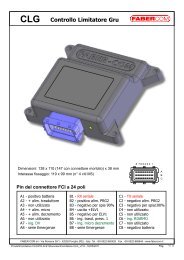
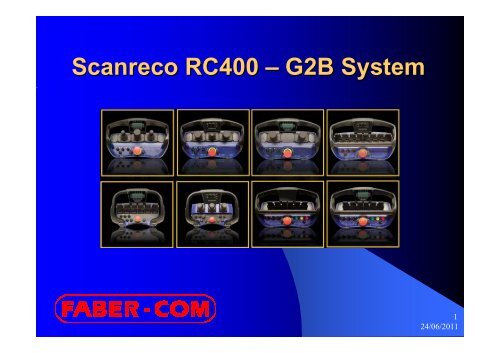
Scanreco RC400 – G2B System124/06/2011
Topics covered in this document:Scanreco RC400 G2B radio controls1. G2B / 1-way and 2-way (can-bus)2. Main differences compared to G2A3. Similarities with G2A4. New opportunities offered by the 2-way displays5. Information required to define the radio control6. Diagnostic mode224/06/2011
G2B: 1-way 1and 2-way2Communication between the transmitter (PCU) and the receiver (CU)Communication can be:- in one direction only (one-way or simplex)- in two directions (two-way or duplex)- EU (433 MHz) and NAFTA (900 MHz) transmission frequencies- Automatic frequency hopping on 50 of the 67 channels available324/06/2011
The two types of PCU, mini and maxi, are the same interms of simplex or duplex transmission.PCU: POSSIBLE CONFIGURATIONS - MAXI: with linear levers (up to 8) - MAXI: with two- and three-axis joystick (e.g. 2-2-2, 3-2-3) - MINI: with linear levers (up to 6) - MINI: with two-axis joystick (e.g. 2-2-2). Three axis not available.10 positions for switches, buttons or potentiometers (5 on the left and 5 on the right)424/06/2011
Commands on the PCUType of ON/OFF operators:- with 2 stable positions ON–OFF (e.g. switch 5-6 / 7-8)- with 3 stable positions ON–OFF–ON (e.g. RPM+/OFF/AutoRPM)- with 3 instable positions (ON)-OFF-(ON) (e.g. RPM+/RPM-)- with 2 instable positions (ON)-OFF (e.g. start button)Special:- with 3 stable + instable positions ON-OFF-(ON)- with 3 positions (3 instable outputs) (ON)-ON-(ON)- with 3 positions (3 stable outputs) ON-ON-ON- with 2 stable positions with mechanical lockButtons with coloured caps (green, red, yellow)Switch with black cap only524/06/2011
Potentiometers on the PCUOne-way potentiometer commands (e.g. concrete pump)side A only or side B only. Adjustment from 0 to MAXTwo-way potentiometer commands (e.g. railway carriage traction)Off in the middle, MAX side A on the left, MAX side B on the rightEach potentiometer uses a proportional function (as if it was a lever)624/06/2011
Number of ON/OFF channels availableON/OFF inputs available on the PCU(20 ON/OFF inputs available on the PCU for switches and buttons + 8 more on the membrane keypad panel)– G1 had 10 inputs – G2 had 13 inputsON/OFF outputs available on the CU(only 14 ON/OFF outputs) – G1 had 10+1, G2 had 13+1 (one permanently reserved for the horn)Number of proportional channels availableProportional inputs available on the PCU(8 linear levers but also 8 analogue inputs in the switch-plate connections,to be used as an alternative)Proportional outputs available on the CU(only 8 proportional channels + one analogue output 0-10V, in the version for concrete pumps724/06/2011
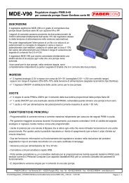
Central Unit (CU)Two basic types of CU:With PWM outputs (Hawe, MOD09, MV99)With DANFOSS outputs (with ratiometric voltage i.e. thevoltage is referred to as a percentage of the supply voltage)…special versions…With PWM outputs + 0-10V analogue outputin the G2s box (for concrete pumps)With 1.5V-5.0V-8.5V fixed voltage outputs(derived from the Danfoss v. with special configuration)for FABER-COM modules (replaces 313)or to interface with PLCs with voltage inputs824/06/2011
Inputs under the switch-plates- mini and maxi G2B have type L2linear levers only- The connectors are duplicatedin the maxi PCU- The removable switch-platesaid processing- G1 and G2 had only 2 analogueinputs in connector 1924/06/2011
ON/OFF outputs and ON/OFF inputs on the CUCAN1024/06/2011
EX1EX2what G2were like1224/06/2011
PROPORTIONAL OUTPUT MAPPINGWhile the G1 and G2 models had various possible configurations for fnumbering the maxi PCU manoeuvres (LEV6 or LEV8)....with G2B models, the levers are always mapped in the same way, , as LEV 8.As with the ON/OFF manoeuvres, there is no longer a direct correspondencewith the outputs for the proportional levers. The levers can be associated asrequired with the proportional outputs using the special WINSCI instructions.N.B. While with the G1 and G2 model, programming took place on the tPCU toremove auto switch-off, with G2B models, this programming must take placeon the CU which then transfers the parameter to the PCU when pairing takesplace.1324/06/2011
Types of panels for DUPLEX versionsSpecial versions with 15 LEDsThe buzzer and display backlighting can also be controlled.1424/06/2011
Graphic display 128 x 64 pixelSplash screen (initial screen)Examples of different-sizedFONTSUse as text with standardFONT (type of character)Various types of bar graph(vertical/horizontal)1524/06/2011
More screen to alternateExample of customer layout1624/06/2011
Special PAIRING for duplex (two-way) way) systemsThe display configuration is memorised in the CU.The pairing procedure for duplex systems requires that after the PCU hasbeen switched off (as with normal pairing), it must be switched back on for asecond pairing phase.In the second phase of pairing, the following are transferred from the CU to thePCU: the ICONS, FONTS, TEXTS, FRAMES to contain the numbers andtexts.During this phase, the display inside the CU continues to revolve e and thedisplay shows the following messages:A transfer is only carried out if necessary.1724/06/2011
Speeds (and SETs) ) availablePARAMETERS: Start – Stop - Micro1824/06/2011
G2B Programming steps (1 of 2)SPEED LEVELSThe G2B has up to three speed SETsFor each SET the following parameters can be programmed:Step Description acoustic signal Level 1 Inversion of the working direction •SET1 Level 2 Normal mode START (minimum) • • Level 3 Normal mode MAX (end stroke) • • • HARE Level 4 Normal mode MICRO (end stroke) • • • • TURTLE Level 5 Acceleration ramps⎯ • Level 6 Deceleration ramps⎯ • •continue ...1924/06/2011
G2B Programming steps (2 of 2)Step Description acoustic signal Level 7 Normal mode START (minimum) ⎯ • • •SET2 Level 8 Normal mode MAX (end stroke) ⎯ • • • • HARE Level 9 Normal mode MICRO (end stroke) ⎯ ⎯ • TURTLE Level 10 Acceleration ramps ⎯ ⎯ • • Level 11 Deceleration ramps ⎯ ⎯ • • •SET3 Level 12 Normal mode START (minimum) ⎯ ⎯ • • • • Level 13 Normal mode MAX (end stroke) ⎯ ⎯ ⎯ • HARE Level 14 Normal mode MICRO (end stroke) ⎯ ⎯ ⎯ • • TURTLELevel 15 Dump Valve (DV) switch off delay⎯ ⎯ ⎯ • • •N.B. the steps for calibrating the RAMPS of SET3 are missing, and are only accessible withWINSCICAUTION: when in programming mode, the radio control operates in the SETbeing programmed (identified by the current programming step).2024/06/2011
Limits to programming via cableWhile with the G1 and G2 models, it was not possible to limit access cess toprogramming via cable (it was enough to know the number of theprogramming step to go to)…with G2B models, it is possible to use a WINSCI instruction to specify sindividually for each programming step whether it is possible to modifythat step or not.When a step is disabled, the parameter value is displayed but cannot bemodified.N.B. from WINSCI there are no limits (it is not currently possible tomanage access using a password and a log record).2124/06/2011
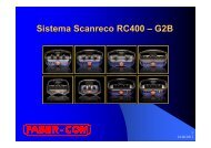
CAN-BUS on all receiversAll the central units have the CAN-BUS interface as standard.The CAN interface is used to:- read the proportional and ON/OFF manoeuvres that the operatorperforms on the PCU- send the information to be shown on the PCU, with the LEDs, with h thebuzzer, with the display- send the CU set change and slowdown commands (and therefore alsomanoeuvre lock commands)- The free Scanreco “GraphicConfigurator” program allows to customers to designand test its proper display layout.An electronic control unit is needed by the client that then processes thedata gathered on the machine and sends the messages to the radiocontrol.Protocol available: CanOpen only (no CanKingdom, , no J1939, noProfibus)2224/06/2011
CANBUS data packetsProportional manoeuvre values- ON/OFF function values- Switches and buttons- PCU on or off- MICRO level active- PCU battery level- Radio signal quality2324/06/2011
Example of application with CANBUSIf the application is very simple, i.e. you just want to display:- a weight attached to the hookor- a pressure in a jack- the length or the angle of an arm- the oil temperatureWe can supply the electronic card that reads the transducer,normally with a 4-204mA output signal, and transmits the messageto be displayed to the radio control, via CANBUS.The Faber-Com MDC420U card do just this...2424/06/2011
2524/06/2011
Other differences between G1/G2 and G2BWith the G1 and G2 models, only the CU memorised the PCU code (andmultiple CUs could be commanded at the same time by simply making thesame PCU recognise them).In G2B systems, this system of communication between the PCU and the CUno longer works.The PCU memorises the CU code and then transmits it in the telegram. Theother CUs, with which pairing took place previously, no longer recognise it.A single PCU for multiple CUs (multi operation mode)It is still possible to control multiple CUs using the same PCU, but the systemmust be especially configure for this (with special WINSCI instructions).Multiple PCUs for a single CU (multi transmitter mode)In order to have multiple PCUs already paired with the receiver and ready touse, without having to perform pairing every time.2624/06/2011
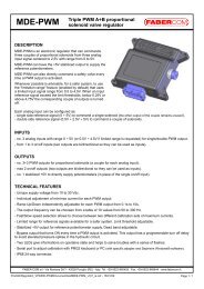
MOP = Multi Operation ModeUC1 UC2 UC3One PCU for multiple receivers (CU)While with G1 models, it was automatically possible to control multiple receivers with asingle PCU (it was enough ensure each receiver recognised it), with G2B models, thisoperating mode is considered to be special.It is necessary to configure each receiver (using special WINSCI instructions) and thenensure each receiver recognises the PCU.With MOP_ACT, it is necessary to activate this working mode. All the CUs that thePCU is programmed to recognise must have MOP_ACT set, otherwise the pairing iscleared.With MOP n , a number is assigned to each receiver, which can then be activated withthe DF n, possibly inverted.With MOP_ALL n , all the receivers can be activated at the same time.2724/06/2011
Multi Transmitter ModePCU1Multiple PCU for a single CUWhen Multi Transmitter mode is activated (MULTI_PCU)parameter) on the receiver, up to 4 different PCU codescan be memorised, to be used as an alternative, withouthaving to perform pairing every time.Simply perform pairing on the various PCUs.It is necessary to reboot the CU or wait 3 minutes in orderto use another PCU.PCU2This mode is not compatible with the Multi Operation Modedescribed earlier.PCU3The first PCU that is switched onexcludes all the others.2824/06/2011
Spare PCUIf a spare PCU has to be sent to an end user, there is no need toworry about the PCU software configuration (LEV, OFFT, FNAIN …).All the operation parameters reside on the CU and aredownloaded onto the PCU when pairing takes place.The radio modules and type of display must obviously be thesame type.A one-way PCU can be used instead of a two-way model tocontrol the machine, although it will obviously not be possible tosee the information on the display.2924/06/2011
Questions to identify which version to supply- Type of output (Danfoss, PWM, ON/OFF, CAN-BUS only…)Caution: there are Danfoss PWM (PVHC) models with Deutsch or AMP JPT connectors.- Operating voltage: 12V or 24V (for Danfoss models, the voltage is not important)- Type of output connector (or with terminal connectors – without cable)- Type of PCU (mini, maxi, linear lever, joystick)- number and position of the levers/joysticks- Switch-plate configuration (standard or special?)If there are additional switches, it is important to know:- the type (stable/detent or instable/spring-return)- the direction (standard horizontal or vertical?)- Transmission frequency (Europe CE 433 MHz / Nafta 900 MHz)- Any antenna extension3024/06/2011
Diagnostic modeThis is a special operating mode in which it is possible to access certaininformation regarding the system status.How to enter diagnostic modeIt is possible to enter during normal operation, via radio, by movingthe MICRO switch 15 times to the left (it is then necessary to push it to theright ones, to return to HARE mode - given that the last MICRO speed hasbeen reached). Nothing is shown on the PCU.OperationIn Diagnostic mode, the radio operates as normal.It is important to be able to see the display in the CU (through the window).If we are guiding the crane operator and we ask him what he can see onthe display, we can obtain a lot of information about the problem he is reporting.It is necessary to explain ourselves well and interpret what the operator isreading.3124/06/2011
Diagnostic modeThere are 8 diagnostic steps. Move on to the next step by pressing theON button once (as in programming mode).Information contained in the various steps0 - the current SET (step zero)1 - calibration (the actual output value) of all the proportional outputs2 - the activation status of the 14 ON/OFF outputs on the CU3 - the activation status of the 4 inputs on the CU4 - the last five error codes that occurredDi 00 (SET1) / Di 00. (SET2) / Di 0.0. (SET3)Di 01 1A 35Di 02 On 01 00 On 02 00 On 03 01 … up to On 14 00Di 03 In 01 00 In 02 00 In 03 01 In 04 00Di 04 15 1A …Save current calibrationReload original calibration(dir, start, stop, micro and ramps)(if saved beforehand)3224/06/2011
PCU diagnosticsThe test mode remains the same as for G1 and G2On PCUs with display when test mode is entered:- the LEDs come on in sequence- two bar graph that display the proportionalmanoeuvre in progress (0-127)- the numbers of the digital functions of the activated switches are shownIn the event of an error with a lever: sequence of beeps, the number of beepsindicating the number of the faulty channel.The two LEDS on the PCU are both dual-colour (green/red).3324/06/2011
Types of CU available3424/06/2011
FABER-COM G2B standard – direct manoeuvre mapping3524/06/2011
FABER-COM G2B standard – manoeuvre mapping shiftedOutput cablesOutput cables3624/06/2011