Operator's Maintenance Manual - BlueMoment
Operator's Maintenance Manual - BlueMoment
Operator's Maintenance Manual - BlueMoment

You also want an ePaper? Increase the reach of your titles
YUMPU automatically turns print PDFs into web optimized ePapers that Google loves.
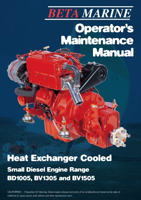
Operator’s<strong>Maintenance</strong><strong>Manual</strong>Heat Exchanger CooledSmall Diesel Engine RangeBD1005, BV1305 and BV1505CALIFORNIA – Proposition 65 Warning: Diesel engine exhaust and some of its constituents are known to the state ofCalifornia to cause cancer, birth defects and other reproductive harm.
Engine DetailsIMPORTANT – Please fill in details at moment of purchase – it really willhelp you! (and it will really help us specify the correct spare parts for you).Engine Type: Power: bhp Speed: rpmBETA WOC NO: K Engine Serial No:Gearbox Type: Serial No: Ratio :1Purchased from:Invoice No:Date:Date Commissioned:Specification / Special Details
ContentsINTRODUCTION 2Engine identification 2Initial receipt of the engine 2Engine storage 2SAFETY PRECAUTIONS 3TECHNICAL SPECIFICATIONS 4SECTION 1: GUIDELINES FOR OPERATION OF ENGINEImportant checks prior to initial use 5Initial start-up and bleeding the fuel system 5Starting/stopping 6SECTION 2: MAINTENANCE AND SERVICE GUIDELINES<strong>Maintenance</strong> schedule: 7Lubrication – checking and changing oil 8Fuel system - pumps, filter, fuel/water separator 9Cooling - fresh water system, keel cooling, heat exchanger 11Sea water pump, heat exchanger 11Belt tensioning 12Air filter 13Electrical 13Laying up - winterising 13Troubleshooting 15Torque settings 25SECTION 3: INSTALLATION GUIDELINESEngine mounting 26Alignment - drives, flanges, flexible drives 26Exhausts & mounting exhausts 27Fuel supply 28Cooling - sea water inlet system 29Calorifier system 30Electrical and installations 31Appendices –wiring diagrams and general arrangements 32Component identification at rear of manual. 62<strong>Maintenance</strong> record 651
OPERATION AND MAINTENANCE MANUAL FOR THE FOLLOWINGBETA MARINE ENGINES BASED ON KUBOTA SUPER 5 SERIESBD1005, BV1305, BV1505This manual has been compiled toprovide the user with importantinformation and recommendationsto ensure a trouble free andeconomical operation of theengine.For further advice or technicalassistance, application should bemade to BETA MARINE LIMITEDor its distributors.All information andrecommendations given in thispublication are based on the latestinformation available at the time ofpublication, and are subject toalteration at any time. Theinformation given is subject to thecompany’s current conditions ofTender and Sale, is for theassistance of users, and is basedupon results obtained from testscarried out at the place ofmanufacture and in vessels usedfor development purposes. We donot guarantee the same results willbe obtained elsewhere underdifferent conditions.ENGINE IDENTIFICATIONNOTE: In all communications withthe distributor or Beta Marine, theengine number, type, and W.O.C.number must be quoted.SAMPLEBD1005, BV1305,BV1505The engine serial number is stampedabove starter motor on the port sideof the engine, and is shown on therocker cover label.INITIAL RECEIPTOF THE ENGINEA full inspection of the engine mustbe made immediately on delivery toconfirm that there is no damage. Ifthere is any damage then write thisclearly on the delivery note andinform your dealer or Beta Marinewithin 24 hours.ENGINE STORAGEThe engine must be stored in a dry,frost free area and this is best done inits packing case. If storage is to bemore than six months then theengine must be inhibited (contactyour dealer or Beta Marine). Failureto inhibit the engine may result in theformation of rust in the injectionsystem and the engine bores, thiscould invalidate the warranty.2
SAFETY PRECAUTIONS!A Keep the engine, gearboxand surrounding area clean,including the area immediatelybelow the engineB DRIVES - Power Take OffAreasi) Gearbox Output Flangeii)The purpose of a marine dieselpropulsion engine is to providemotive power to propel a vessel.Accordingly the gearbox outputshaft rotates at between 280 and2400 rev/min. This flange isdesigned to be coupled to apropeller shaft by the installerand steps must be taken toensure adequate guarding.Forward End DriveEngines are supplied withunguarded vee belt drives topower the fresh water pump andbattery charging alternator. Theinstaller must ensure that it is notpossible for injury to occur byallowing accessibility to this areaof the engine. The three pulleysrun at high speed and can causeinjury if personnel or clothingcome in contact with the belts orpulleys, when the engine isrunning.iii) Power Take Off Shaft(Engine Mounted Option)CShaft extensions are available asan option and rotate at between850 and 3600 rev/min. Ifcontact is made with this shaftwhen the engine is running,injury can occur.EXHAUST OUTLETDiesel marine propulsion enginesemit exhaust gases at very hightemperatures - around 400-500°C. Engines are supplied witheither wet exhaust outlet (waterinjection bend) or dry outlet (dryexhaust stub) - see option list. AtDthe outlet next to the heatexchanger/header tank, theexhaust outlet can become veryhot and if touched, can injure.This must be lagged or avoided byensuring adequate guarding. It isthe responsibility of the installer tolag the exhaust system if a drysystem is used. Exhaust gasesare harmful if ingested, theinstaller must therefore ensure thatexhaust lines are lead overboardand that leakage in the vesseldoes not occur.FUELi) Fuel Linesii)EFDiesel engines are equipped withhigh pressure fuel injectionpumps, if leakages occur, or ifpipes fracture, fuel at a highpressure can harm personnel.Skin must be thoroughly cleanedin the event of contact with dieselfuel.Fuel Supply ConnectionsEngines are supplied with 8 mmcompression fittings. Theinstaller must ensure that whenconnections are made, they areclean and free of leaks.OILThe Beta propulsion is suppliedwith 2 dipsticks, one for theengine and one for the gearbox.Ensure dipsticks are returned andsecure after checking, if not oilleaks can cause infection whentouched. All oil must beremoved from the skin to preventinfection.SCALDINGAn engine running under load willhave a closed circuit fresh watertemperature of 85° to 95°C. Thepressure cap on the top of theheat exchanger must not beremoved when the engine isrunning. It can only be removedwhen the engine is stopped andhas cooled down.G TRANSPORTATION/LIFTINGEngines are supplied ontransportable pallets. Lifting eyeson engines are used for liftingengine and gearbox assemblyonly, not the pallet andassociated kit.GENERAL DECLARATIONThis machinery is not intended tobe put into service until it has beenincorporated into or with othermachinery. It is the responsibility ofthe purchaser/installer/owner, toensure that the machinery isproperly guarded and that allnecessary health and safetyrequirements, in accordance withthe laws of the relevant country, aremet before it is put into service.Signed:J A Growcoot, C.E.O,Beta Marine LimitedNOTE: Recreational CraftWhere applicable, thepurchaser/installer/owner and operatormust be responsible for making surethat the Recreational Craft Directive94/25/EC is complied with.3
TECHNICAL SPECIFICATIONSStandard Engines BD1005 BV1305 BV 1505Cylinder 3 4 4Bore (mm) 76 76 78Stroke (mm) 73.6 73.6 74.8Displacement (cc) 1001 1335 1498CombustionCoolingStarter voltage (V)Starter output (kW)Starter alternator output (Amps)Glow plug resistance (each)Engine speed (RPM)3,600 3,600 3,000Power output to ISO3046 (BHP) 28.0 35.0 37.5Declared power ISO8665 (kW) 19.2 25.7 27.1Compression RatioFuel timing BTDC3 VortexWater121.265 (standard)1ΩCapacity of standard sump approx (litres) 6 7.5 7.5Capacity of shallow sump approx (litres) 5 6.5 6.5Nett dry weight with gearbox (kg) 150 170 170FuelCoolantCoolant capacity approx (H/E litres) 5.5 Diesel fuel oil No.2D33%-50% maximum antifreeze / water7 7Min. recommended battery capacity12V 80Ah (400CCA Min)22:121°Maximum Angle of Installation: Trim 15°, Roll 30° (intermittent), 20° continuousRotation: ANTI CLOCK ON FLYWHEEL, CLOCKWISE ON OUTPUT GEARBOX FLANGE FOR USE WITH RIGHT HAND PROP IN AHEAD, on mechanical gearboxes. Hydraulic gearboxes canbe left or right handed.Diesel fuel must conform to BS2869-1970 class A1 or A2. The fuel must be a distillate and not a residual oil or blend.Lubricant: Engine - Engine oil must meet MIL-L-2104C (see section 2 for details)Gearbox - see operator’s manual for the gearbox oil type and capacityOil pressure – minimum (tickover) 0.5 barPower outputs: These comply with BS EN ISO 8665:1996 crankshaft powerNote: Declared Powers to ISO8665:19951. The declared powers are at the same engine speed as the ISO 3046 figures. This speed is the speed related to the outputs / powers shown.2. Declared powers are at the gearbox coupling (coupling to the propeller shaft) as per clause 3.2.1 with standard specifications as per our current price lists.Additional accessories or alternative gearboxes may affect the declared powers.3. Operation at parameters outside the test parameters may affect the outputs / powers which in any case are subject to the ISO tolerance bands.4
SECTION 1GUIDELINES FOR OPERATION OF ENGINEIMPORTANT CHECKS PRIORTO INITIAL USE1. Generally, a new engine has theoil and anti-freeze removed afterthe works test. Fill the enginewith the correct oil and antifreeze(see sections on ENGINEOIL and COOLING). Checkgearbox oil level - see separateoperator's hand book.2. Ensure the engine is free to turnwithout obstructions.3. Ensure battery is fully chargedand connected (the isolator is inthe 'ON' position).4. Ensure Morse speed and gearboxcables are fitted correctly and thatcable travel lengths are correct.Gear selection lever –allmechanical gearboxes: caremust be taken to ensure thatthe remote control cable isadjusted so that the selector leveron the gearbox moves FULLtravel and brought “hard up”against its end stop in bothdirections. Failure to achieve thecorrect adjustment will reduceefficiency of the clutch and maycause slippage at low revs.Warranty will not be acceptedon gearboxes returned in thewarranty period for failure dueto incorrect adjustment.5. Ensure engine is out of gear with1/3 throttle - see single levercontrol instruction manual.6. Open the fuel stopcock and bleedthe fuel water separator of air asshown in manufacturersliterature.7. Fuel should now be at the fuel liftpump, see diagram 1a. Open thesea cockINITIAL STARTUP ANDBLEEDING THE SYSTEM(a) Open fuel bleed screw on fuelfilter assembly by 1 1 /2 turns. Seediagrams 1a & 1b.(b) Move hand priming lever on fuellift pump up and down until fuelwith no bubbles comes out of thebleed screw.(c) Shut/tighten the bleed screw.Clean area thoroughly with tissuepaper.(d) Continue to hand prime for 30seconds to push fuel through thefuel pump.(e) Start engine (see normalstarting).Note the engine may have to beturned over with the starter for afew seconds before it fires. Donot run the starter for more than20 seconds. If the engine has notstarted after 20 seconds thendisengage the starter andcontinue to hand prime for afurther 30 seconds, then repeat.(f) If engine does not start after 3attempts then allow 5 minutesfor the starter to cool down beforerepeating (a) to (e).Note: The starter windings can beburnt out with continuous crankingDiagram 1aCAUTIONTo avoid personal injury:• Do not bleed a hot engine as thiscould cause fuel to spill onto a hotexhaust manifold creating a dangerof fire.• Do not mix gasoline or alcoholwith diesel fuel. This mixture cancause an explosion.• Do not get diesel on the flexiblemounts – they will deterioraterapidly if soaked in diesel.• All fuel must be removed from skinto prevent infection.Diagram 1b5
NORMAL STARTING (BETAPANELS WITH SILVER KEYSWITCH,FOR KEYLESS SEE PAGE 23)With the engine out of gear, set speedcontrol lever to 1/3 throttle. Turn key anticlockwiseto HEAT* (A) position and holdfor ten seconds, turn key clockwise toRUN (C) position. At this stage theinstrument panel should illuminate, analarm buzzer will sound and two (orthree*) red warning lights will illuminate:STARTER BATTERY CHARGEDOMESTIC BATTERY CHARGE (D inbattery symbol - AB & C Deluxepanels only)*(Note: this will only illuminate if2nd alternator is fitted)OIL PRESSUREand green POWER ON / RUN LIGHT(this will stay on)Turn to START (D) position and enginewill motor, hold in position untilengine fires (see initial start-up sectionfor maximumtime starter canbe used).Release key(when enginehas started) toRUN position.Ensure alarmAHEATBOFFCRUNDSTARTbuzzer is not sounding and thatwarning lights are extinguished. If oneor both of the alternator warning lightsare still on, then increase enginespeed to excite the alternator - thenreturn to idle. The battery chargelights should then go out. The runlight will remain on (green lamp).Check for sea water flow. If no flowthen SWITCH OFF IMMEDIATELYAND CHECK SEA WATER SYSTEM.Note: for some deluxe panel with theblack keyswitch, they operateclockwise as legend on panel (OFF –RUN – HEAT – START). Operation forengine start procedure is the same asstandard apart from this.STOPPINGEvery propulsion engine is fitted witha stop solenoid which is energised tostop. To stop engine simply pressstop push button, hold in until enginestops, then turn key from ‘RUN’ to‘OFF’ position.When leaving the boat for anextended period,• Turn off sea-cock (heat exchangercooled engines).• Turn off battery isolator.Do not turn the key to the offposition when the engine isrunning. This will damage thealternator.*WARNINGDo not leave the key in ‘HEAT’position for more than 15 seconds -this will damage the heater plugsand eventually lead to poor starting.Do not depress stop button for morethan 10 seconds as this will lead tooverheating and failure of thesolenoid.The Super 5 range of engines areequipped with a mechanical stoplever in the event of electrical systemfailure. This lever is located on thestarboard side of the engine abovethe speed control lever. See Fig 2e:Stop leverSpeed leverFig. 2e6
SECTION 2MAINTENANCE SCHEDULEDAILY OR EVERY 8 HOURSRUNNING• Check engine oil level.• Check gearbox oil level.• Check coolant level.• Check battery fluid.• Check drive belt tension• Ensure raw water inlet strainer isclear.• Check stern gland lubrication.• Drain off any water in fuel waterseparator.AFTER THE FIRST 25 HOURSRUNNING• Change gearbox lubricant (Seeseparate gearbox manual).• Check that all external nuts,bolts and fastenings are tight.See table for torque values.Special attention should be paidto the flexible mount lock nuts,these should be checked fortightness, starting with lower nutfirst in each case. If the lowernuts are found to be very loose,then the alignment of the shaftto the gearbox half couplingshould be re-checked. Pooralignment due to loose flexiblemount nuts will cause excessivevibration and knocking.• Check the belt tension on anysecond alternators fitted andadjust –see page 12.• Check ball joint nyloc nuts fortightness on both gearbox andspeed control levers. Greaseboth fittings all over.AFTER FIRST 50 HOURS• Change engine lubricating oil.• Change oil filter.• Check for leaks on header tanktubestack. Tighten end cap boltif required.• Drain off any water in fuel/waterseparator.EVERY 150 HOURS• If shallow sump (option) isfitted, change engine lubricatingoil and filter.EVERY YEAR – OR EVERY 250HOURS IF SOONER• Change engine lubricating oil(standard sump)• Change lubricating oil filter• Check air cleaner element• Check sea water pump impellerand change if worn.• Check wasting anode condition,replace when necessary. Insome environments this may be6 montly or less.• Remove heat exchanger tubestack, by undoing the bolt eachend of the tube stack. Removeend cover, pull out tube stackand clean. Replace rubber ‘O’rings and re-assemble.Immediately engine is startedcheck for leaks.• Spray the key switch withWD40 or equivalent to lubricatethe barrel.• Check that all external nuts,bolts and fastenings are tight.See table for torque values.• Check ball joint nyloc nuts fortightness on both gearbox andspeed control levers. Greaseboth fittings all over.EVERY 750 HOURS – As every250 hours plus the following:-• Change air cleaner element.• Change fuel filter.• Change antifreeze.• Change gearbox oil.• Check electrical equipment,condition of hoses and belts,replace as necessary.7
LUBRICATIONEngine oil: Engine oil should be MIL-L-2104C or have properties of APIclassification CC/CD/CE grades. Thefollowing table gives grades of oilrequired for various ambienttemperatures.Note: A good quality 15W/40mineral or multigrade oil as used inmost diesel car engines will meetthese requirements. Do not use‘Turbo Diesel Oil’ or additives.CHECKING ENGINE OILLEVELFor quantities of oil required seesection marked ‘TechnicalSpecification’, Page 4When checking the engine oil level,do so before starting, or more thanfive minutes after stopping.1. To check the oil level, draw outthe dipstick, wipe it clean, reinsertit, and draw it out again.Check to see that the oil level liesbetween the two notches.2. If the level is too low, add new oilto the specified level - Do notoverfill.IMPORTANTWhen using an oil of different makeor viscosity from the previous one,drain old oil. Never mix two differenttypes of oil. Engine oil should bechanged after first 50 hours runningtime and then every year or every250 hours if sooner. Oil filter is acartridge type mounted on the portside of the engine.AMBIENT TEMP SINGLE GRADE MULTI GRADE-30°C TO 0°C SAE 10W SAE 10W/30-15°C TO +15°C SAE 20W SAE 15W/400°C TO +30°C SAE 30 SAE 15W/4025°C AND ABOVE SAE 30 SAE 15W/40CHANGING ENGINE OIL(1) Run the engine for 10 minutes towarm up the oil.Oil goesin here(2) Your engine is provided with asump drain pump. Unscrew theend cap on the end of the pump,turn the tap to ‘on’. Use the handpump as shown to pump out theoil into a bucket. Turn the tap tooff position and replace end cap.See diagram 2c.(3) Unscrew the oil filter and replacewith a new one. See diagram 2d.Fig. 2aFig. 2b. Dip stickNote: It is best to have a plasticbag wrapped round the filter tocatch any oil left in the system.(Always keep your bilges clean!)Before screwing in the new filterspread a thin film of oil round therubber gasket to ensure a goodseal and screw in – hand tight.Sumppump(4) Fill the engine with new oil asdescribed above.End CapFig. 2cFig. 2dOil filter(5) Run the engine and check for oilleaks8
CHECKING GEARBOX OIL LEVEL(1) The gearbox is fitted with a dipstickand oil filler plug, see fig 2e.(2) Each engine is supplied with agearbox operators manual whichspecifies the type of lubricatingoil to be used, the capacity andfrequency of changing of the oil.(3) New engines are normallysupplied with the gearbox toppedup with lubricant but Check thelevel before starting the enginefor the first time.(4) The oil can be changed via thedrain plug at the bottom of thebox or sucked out with a handpump via the filler plug.(5) A guide to the type of oil to beused is as follows:Gearbox Lubricant Capacity (approx)TMC40M Use ATF Oil 0.2 litresTMC60M Use ATF Oil 0.8 litresPRM 80 Use Engine Oil 15W40 0.6 litresPRM 120 Use Engine Oil 15W40 0.8 litresPRM 150 Use Engine Oil 15W40 1.4 litresPRM 260 Use Engine Oil 15W40 1.5 litresZF10M Use ATF Oil 0.35 litresZF15M Use ATF Oil 0.55 litresTTMC 35A-2 Use Engine Oil 15W40 0.65 litresNote: ATF is Automatic Transmission FluidFig 2eDipstickOilfillerplugOil drainplugFUEL SYSTEM(see page 28 for a typical installation)IMPORTANT• Always fit a fuel/water separatorin the fuel supply system. Waterin the fuel can seriously damagethe injection system.• If a fuel supply shutoff valve isfitted do not use a taper tap, onlyuse a ball valve tap. The ballvalve type are more reliable andless likely to let air into the fuelsystem.• Be sure to use a strainer whenfilling the fuel tank. Dirt or sandin the fuel may cause trouble inthe fuel injection pump.• Always use diesel fuel.• Do not use kerosene, which isvery low in cetane rating, andadversely affects the engine.• Be careful not to let the fuel tankbecome empty, or air can enterthe fuel system, necessitatingbleeding before next engine start.• The fuel lift pump will only liftfuel through 0.25 metres. If thisis insufficient then an electric fuellift pump must be fitted. Drawing202-06421, illustrating thewiring of a typical electric fuel liftpump with ignition switchedrelay can be supplied uponrequest..FUEL FILTER REPLACEMENT1. The fuel filter is a spin on type.Remove by turning anti-clockwisewhen viewed from below.2. Replace the fuel filter cartridgeevery 750 hours. See fig. 2g.3. Apply fuel oil thinly over thegasket and tighten into position -hand tight.4. Bleed as detailed - see initialstart up.95. Check for leaks.6. Do not get fuel on the flexiblemounts.Fig. 2g
COOLINGBD1005, BV1305 and BV1505engines are normally fresh watercooled. This water circulates throughthe engine and on to a heatexchanger where it is cooled by seawater which is pumped through thecooling tubes. The sea water is theninjected into the exhaust system (seediagram).FILLING THE FRESHWATER SYSTEMNew engines are supplied with thefreshwater drained off. The followinginstructions must be followed to fillthe system.(a) Mix up in a clean bucket a 33 to50% antifreeze to fresh watersolution. For the volume requiredsee technical specificationpage 4.(b) Check that the drain tap or plugis turned off. (see fig 2l)(c) Fill engine with freshwater/antifreeze solution through the top ofthe heat exchanger or headertank with the filler cap removed.(see fig 2m).(d) Fill header tank to the top of thefiller neck and replace cap. Pressdown firmly on filler cap andhand tighten in a clockwisedirection.(e) Run the engine for 5 minutes onno load (out of gear) and checkcoolant level. Top up asnecessary.(f) Check system for leaks.(g) If a calorifier is fitted care mustbe taken to see that this is alsofull of coolant and all the air isexpelled. (See calorifier fittingnotes under Section 3).(h) Run the engine on one third loadfor 15 minutes, preferably withthe boat tied up. As the systemwarms up coolant may beexpelled from the overflow pipeinto the bilge. Stop the engineand allow the engine to cooldown before removing thepressure cap and top up thecoolant to one inch below thefiller neck.DrainTap orplugFig. 2lFig. 2m10
IMPORTANTRemoval of the pressure cap whenthe engine is hot can cause severeinjury from scalding hot water underpressure. Always allow the engine tocool and then use a large cloth whenturning the cap anti-clockwise to thestop. This allows the pressure to bereleased. Press firmly down on thecap and continue to turnanticlockwise to release the cap.(i) Repeat (h) if coolant level is morethan one inch below the base ofthe filler neck when the enginehas cooled down.(j) Run engine on 2 /3 full load for 20minutes, check for leaks andrepeat (i).(k) Anti-freeze solutions should bedrained off every 2 years andreplaced with a new solution.Note: When draining fresh watersystem, ensure the engine has cooledsufficiently to prevent scalding fromhot pressurised water. Prior todraining a cold engine, remove thefiller cap from the header tank andthen open the water drain tap. Thisallows the water to drain freely fromthe system.YACHTS AND LAUNCHES WITH HEAT EXCHANGER COOLINGIt is essential that a 33% to 50%anti-freeze/water mixture is used.This not only stops freezing up inwinter, but it prevents overheatingand corrosion.The warranty is invalid unless thecorrect ratio is used.Concentration of ethylene should notexceed 50%.The anti-freeze in the fresh watersystem enables the boiling point ofwater to rise to 124°C with a 13 psipressure cap fitted. The watertemperature alarm switch willhowever be activated at 95° to100°C. If no anti-freeze or a veryweak solution is used, then the watertemperature switch may not beactivated before coolant is lost.SEA WATER PUMP AND COOLING SYSTEM(HEAT EXCHANGER-COOLEDENGINES)CAUTIONBefore working on the sea watersystem ensure that the sea cock is inthe off position.(1) It is very important that thecorrect sea water flow ismaintained to cool the closedcircuit system of the engine. Thekey component in this system isthe sea water pump impeller.This should be checked everyyear by removing the circularplate (see fig. 2h).(2) Withdraw the rubber impellerfrom its drive shaft as shown.See diagram 2i.(3) Check impeller for cracks in therubber, excessive wear or lostvanes. Replace with a newimpeller as necessary.Note: If any pieces of rubberimpeller are missing then theymust be found as they are mostlikely to be trapped in theentrance to the heat exchangercooling stack. See ‘Cleaning TubeStack’.Fig. 2hFig. 2I11
CLEANING THE HEAT EXCHANGER TUBE STACK AND REPLACING WASTING ZINC ANODE(1) The wasting zinc anode shouldbe checked every six months andreplaced every year or asnecessary. The anode is attachedto the bolt inserted in the aft endcap of the heat exchanger. Seefig. 2j.(2) Unscrew the bolt and replace thecomplete unit with a new one.(3) Check for leaks.(4) It is possible for fine sea weedand other debris to get past theinlet filter and into the tube stack.This should be removed andcleaned. See fig. 2k.(5) Drain off coolant into a bucket.(6) Unscrew the 2 end cap retainingbolts (one each end of the tubestack). Remove the ‘O’ rings andpull out tube stack. Clean tubestack and end caps.(7) Re-assemble using new ‘O’ rings.Do not overtighten end cap boltsand make sure the tube stack isthe right way round.(8) Re-fill engine with water/antifreezesolution and run engine upto temperature to check for leaks.ZincAnodeFig. 2jFig. 2kBELT TENSION65 AMP ALTERNATOR (HEAT EXCHANGER COOLED)Link adjust boltWARNINGBelt tension must only be checkedwith the engine switched off.(1) On heat exchanger cooled enginesa single 65 amp is fitted asstandard. These alternators areadjusted as follows.(2) The belt tension is adjusted byswinging the alternator outboardas it pivots on its power supportbolt.(3) With the engine stopped, loosenthe support bolts and the linkadjusting bolt.100 AMP ALTERNATOR (OPTION)The same method, as outlined aboveapplies, but final tensioning must beby hand only. Over tensioning will(4) Push alternator outboard totension and tighten link bolt.Check that the depression of thebelt at position shown isapproximately 1 /2” or 12 mmwhen pushed down firmly bythumb. Tighten support bolts.(5) Belt tension should be regularlychecked especially during thefirst 20 hours of running in anew belt, as stretchingoccurs.Belt tension must only bechecked with the engineswitched off.cause premature failure ofcomponents.Support bolts12
AIR INTAKE FILTERThese engines are fitted with an air intake filter which should be checked every season and changed every 2 years orsooner if badly clogged. If badly clogged, check more often.1 23MAINTENANCE - ELECTRICALWARNINGUnder no circumstances should thebattery be disconnected or switchedoff when the engine is running. Thiswill seriously damage the alternatorPANELS AND WIRINGSee installation notes, page 31.GENERAL MAINTENANCE(1) The panel must be protected fromrain and sea water, see installation.Sea water entering the keyswitch will eventually causecorrosion and could result in thestarter motor being permanentlyenergised and burning out. Spraykey switch every month with WD40 or equivalent.(2) Check batteries for acid level andtop up if required. For lowmaintenance and ‘gel’ batteriessee manufacturers instructions.(3) Loose spade terminalconnections are the mostcommon cause for electricalfaults - check on a regular bases(see maintenance instructions).WINTERISING AND LAYING UPHEAT EXCHANGER COOLEDENGINES LEFT AFLOAT ANDASHORE(a) The engine oil and oil filtershould be changed at the end ofthe season rather than in thespring. See section 2.(b) The closed circuit system shouldcontain a 50/50 solution of antifreeze(this also applies to warmand tropical climates).(c) For cold climates where the air orwater temperatures can fallbelow 3°C, the sea water circuitmust be protected in addition tothe fresh water system. This isbest achieved as follows:LAYING UP ASHORE(i) Close the inlet seacock to theengine (engine stopped).(ii) Disconnect the sea waterinlet pipe and dip it into a smallbucket containing 50/50 antifreezesolution.(iii) Start the engine (out of gear)and run for 5 to 10 seconds untilthe anti-freeze is used up andcan be seen coming out of theexhaust outlet.(iv) Shut engine off andreconnect the inlet pipe to theseacock.The sea water or raw watercircuit is now protected by antifreeze.(d) Ensure instrument panel is wellprotected and give the key switcha spray of WD 40 or equivalent.(e) With the engine stopped,disconnect the battery (alwaysdisconnect the negative cable firstand re-connect the negativecable last) and take it ashore fortrickle charging and top up asnecessary. If AC power isavailable then this can be doneon the boat.(f) Fuel tanks should be kept fullduring the lay up period toeliminate water condensation inthe tank. Water entering the fuelinjection system can causeconsiderable damage.(a) Change the engine oil before theboat is taken out of the water.Warm engine oil is much easierto pump than cold!13(b) to (f) should be followed asabove.
TROUBLE SHOOTINGBeta diesels are very reliable if installed and serviced correctly, but problems can occur and the following list gives themost common ones and their solution.PROBLEM ENGINE DOES NOT START BUT STARTER MOTOR TURNS OVER OKPossible CauseNo fuel:Air in fuel system:Water in fuel:Blocked fuel pipe:Fuel filter clogged:Fuel lift pump blocked:Blocked injector:Fuel return not fed back to the tank:Heater plugs not working:Stop solenoid stuck in off position.SolutionTurn fuel cock on and fill tank.Vent air (see initial start-up)Change fuel filter and bleed system.Clean out and bleed system.Change filter and bleed system.Remove and replace.Remove and clean.Re-route fuel return pipe.Check wiring to the plugs, and replace plugs if they are burnt out.Check solenoid is free to return to run position.PROBLEM: STARTER MOTOR WILL NOT TURN OR TURNS OVER VERY SLOWLYPossible CauseBattery discharged:Starter motor flooded with sea water:Wiring disconnected or loose:Water in cylinders:Engine harness fuse blown:SolutionCharge battery or replace. Check alternator belt tension.Remove and clean or replace.Check circuit for loose connections.Incorrect installation. This is serious - check engine oil for signs of water(creamy-coloured oil). Ring your dealer.Replace fuse (located by starter motor or above flywheel housing) and checkfor wiring faultsFUSE (If located by starter motor, usually it is positioned above flywheelhousing at rear of engine)Note: For convenience, some engines are supplied with a spare fuse andholder attached onto the main engine fuse holder.14
PROBLEM: ERRATIC RUNNINGPossible CauseAir in fuel supply:Fuel lift pump faulty:Clogged fuel filter:Fuel return not fed back to the fueltank, or blocked pipe:Air filter blocked:Worn or blocked injector:Engine rpm in gear is too low, thismust be 850 min:Faulty stop solenoid:Broken fuel injection pump spring:SolutionCheck supply system for leaks and fix.Replace.Replace.Re-route pipe or clean.Replace.Service injectors.Increase engine tick over speed.Disconnect wiring to solenoid. If running improves check for a wiring fault.Replace.PROBLEM: WHITE OR BLUE EXHAUST GASPossible CauseEngine oil level too high:Blocked injector:Piston ring and bore worn, giving alow compression:Check that the breather pipe is clearand not obstructed:SolutionReduce the level.Service injectors.Get compression checked by your dealer or Kubota service agent. He willadvise action to be taken.Remove and clean out.PROBLEM: BLACK EXHAUST GASPossible CauseSolutionBlocked air filter element:Over pitched propeller - engine willnot reach its full rpm:Inspect and replaceGet the propellerre-pitched if necessary.Accumulated debris on hull:PROBLEM: LOW POWER OUTPUTInspect and clean if requiredPossible CausePropeller is too big:Check gearbox reduction ratiorelative to propeller size:SolutionChange or depitch.Change.15
PROBLEM: LOW POWER OUTPUTPossible CauseSolutionBlocked fuel filter:Blocked air filter:Air in fuel system:Governor spring incorrectly mounted:Single lever control not operatingcorrectly:The electrical load is too large on startup.Replace.Replace.Check system.Dealer to adjust.Disconnect speed control cable and move the lever by hand. Adjust cable.Disconnect or reduce the load.PROBLEM: HIGH OIL CONSUMPTIONPossible CauseSolutionOil leaks:Piston rings worn:Valve stem and guide worn:Piston rings gap facing the samedirection:Check for leaks.Overhaul required.Overhaul required.Shift ring gap position.PROBLEM: WATER IN LUBRICATING OIL - (Heat exchanger cooled)Possible CauseOil goes “milky” due to sea waterentering exhaust manifold:SolutionCheck installation - has anti-siphon valve been fitted? Change engine oil andrun engine for 10 minutes each time to eliminate any water. Get fuel injectionpump and compression checked by Service Agent.PROBLEM: WATER IN LUBRICATING OIL - (General)Possible CauseCore plug pushed out due to frozenblock:Water pump seal damaged:SolutionService Agent to check and replace.Service Agent to check and replace.PROBLEM: WATER IN LUBRICATING OIL - (Keel cooled)Possible CauseOil goes “milky” due to water enteringexhaust manifold and then into thesump:SolutionCheck installation – has dry exhaust system been fitted correctly, ensuring rainwater cannot enter the exhaust port and run back? (See DRY EXHAUSTSYSTEM) Change engine oil and run engine for 10 minutes each time toeliminate any water. Get fuel injection pump checked by Service Agent.16
PROBLEM: LOW OIL PRESSURE WARNING LIGHT COMES ON WHEN ENGINE SPEED REDUCED TO TICK OVER:Possible CauseFaulty switch sender:Engine running too hot:Oil relief valve stuck partially openwith dirt:Blocked oil filter:Wiring fault:Insufficient oil:SolutionReplace.Check cooling water flow (see section 2 Cooling).Remove and clean.Change.Check circuit.Top up and check for leaks.PROBLEM: PANEL REV COUNTER NOT WORKING (WHEN FITTEDPossible CauseNo W connection to alternator.Wiring fault:SolutionCheck power output from ‘W’ connection. Should be about 9V AC.Check circuit.PROBLEM: ENGINE OVERHEATSPossible CauseCheck coolant level:Insufficient sea water flow:Damaged or worn pump impeller:Blocked tube stack in heatexchanger:Zinc anode flakes blocking tube stack:Pressure cap loose:Switch sender faulty:Inlet sea cock is too small:High exhaust back pressure:Air locks in cooling pipe work to keelcooler:Keel cooler of insufficient size:SolutionTop up.Clear blocked intake or filter.Replace.Remove tube stack and clean - replace ‘O’ rings.Remove and clean tube stack as above.Replace.Replace.Replace (see heat exchanger cooled seawater inlet system in section 3).Must not exceed 3.1” of Hg.Vent the system and top up coolant.Contact boat builder.17
GENERAL -HEAT EXCHANGE ONLY:The most common cause ofoverheating is insufficient seawaterflow due to a blocked intake (weedor a plastic bag!). If this happensthen clear the blockage. If theproblem is not cured then check thesystem for sea water flow whichshould be 6.5 litres / minuteminimum at 1,000 rpm as follows:(a) With the boat tied up and out ofgear run the engine up to 1000 rpm.*Hold a plastic bucket over theexhaust outlet for 10 seconds andmeasure the amount of watercollected. Multiply this value by 6 togive the flow in litres/min. Repeattwice and take an average. If the flowrate is noticably less than the 6.5litre per minute minimum, then:(b) Check impeller in sea waterpump - if worn replace.(c) If impeller has a vane missingthen this will be lodged either in thepipe to the heat exchanger or in theend of the exchanger. This must beremoved.(d) Check flow again as in (a).*Note: This operation must only bedone in safe conditions, in port andwith two assistants.Working from a rubber dinghy isbest. The person holding the bucketshould take precautions againstbreathing in the exhaust gasses.PROBLEM: KNOCKING NOISEPossible CausePropshaft touching gearbox outputcoupling through split boss or Type 16coupling:Flexible mount stud touching enginebed:Drive plate broken:Engine touching engine bed:SolutionAdjust, giving correct clearance (10mm) between gearbox and propeller shaft.Adjust stud to clear.Replace / repair.Re-align engine / modify bed.PROBLEM: BATTERY QUICKLY DISCHARGESPossible CauseHigh load and insufficient running:Low electrolyte level:SolutionReduce load or increase charging time. Large domestic battery banks subjectto high electrical loads will take a considerable time to recharge from a singlealternator.Top up.Fan belt slipping - black dust inengine compartment: Enginecompartment temperature too high:Alternator defective:Battery defective:Poor wiring connection:Adjust tension / replace belt with a high temperature and/or improve enginecompartment ventilation.Check with Agent.Replace.Check wiring system.18
PROBLEM: TRANSMISSION NOISEPossible CauseCheck gearbox oil level:“Singing” propeller:Drive plate rattle at tickover:Worn drive plate:Propellor shaft hitting the gearboxhalf coupling:SolutionTop up.Check with supplier.Check engine rpm (must be 850 rpm minimum in gear).Change.Move shaft back to give at least 5mm clearance (type 12/16 couplings only)PROBLEM: VIBRATIONPossible CausePoor alignment to shaft:Flexible mounts not adjusted correctlyto take even weight:Flexible mount rubber perished:Loose securing nut on flexible mount:Insufficient clearance between thepropeller tip and the bottom of theboat:Loose zinc anode on the shaft:Worn cutless bearing or shaft:Weak engine support/bearers:SolutionThe alignment must be accurate even if a flexible coupling is used (see section3 ALIGNMENT).Check relative compression of each mount.Replace. (Diesel or oil will eventually perish most rubbers.)Check alignment and then tighten the nuts.There must be at least 10% tip clearance between propeller and bottom of theboat (ie 10% of the propeller diameter as clearance). Refer to boatbuilder.Tighten or replace.Replace.Check for cracked or broken feet.PROBLEM: MORSE CONTROL CABLE WILL NOT FITPossible CauseFitting incorrectlySolutionCables are being fitted the wrong way around, switch over and fit the oppositeway.19
ELECTRICAL FAULT FINDING & TROUBLE SHOOTING –ENGINES BUILT AFTER JULY 2005 ONLYThe following chart is compiled to aiddiagnosis of electrical faults, based onthe Beta 10-90hp range of engines. Ifyour engine was built before July2005, contact Beta Marine for therelevant electrical trouble shootingguide.Standard sea specification engines(heat exchanger cooled) are suppliedwith a single alternator, mounted portside, supplying power to starter batteryand control panel.Standard canal specification engines(keel cooled) are supplied with twinalternators:• 1st alternator, mounted port side,supplying power to starter batteryand control panel• 2nd alternator, the standardmounting position for this is abovethe engine on the starboard side(or below 1st alternator on 75 &90hp), supplying power to thedomestic battery system.Both of these alternators workindependently, if the domestic batterysystem is disconnected, the enginewill still run correctly but:• Domestic charge warning lampwill not function• Warning buzzer will remain on atall timesStandard control panels are suppliedwith four or five lamps:Four lamp panels:A, ABV, ABVW, B, these panels utilisebulbs inside sealed lamp holdersFive lamp panels:AB or Deluxe C, these panels alsoutilise bulbs inside sealed lampholders, having an additional lamp fordomestic battery chargeWith keyswitch* in run position &engine off:• Red lamp for no starter batterycharge should function• Red lamp for no domestic batterycharge should function (Note: thiswill only function if a secondalternator is fitted to the engineand connected to a chargedbattery)All Beta panels have the following warning lamps:Starter battery charge warning lamp• Red lamp for high enginetemperature should not function(when engine is cold / cool /warm). This lamp will only everfunction if the engine is overtemperature.• Red lamp for low oil pressureshould function• Green lamp for panel power onshould function• Buzzer should sound* For operation of engines controlledwith keyless panels refer to ‘correctoperation of keyless panels’ later inthis sectionWhen the engine is started, all the redwarning lamps should switch offleaving just the green power onindication lamp illuminated. The oilpressure lamp may take a fewseconds to switch off and the chargefail lamp may remain on until enginerpm is increased to approximately1,000rpm (if the engine was startedat tickover).Before investigating any specificelectrical problem, always check:• Connection between panelharness and panel loom. It mustbe clean, dry and secured with acable tie.• Check the start battery isconnected to the correct terminalon the starter motor.• Check the domestic battery is20(A, AB, ABV, ABVW,B and C Deluxe)Red• High engine temperature warning lamp Red• Low engine oil pressure warning lamp RedAll panels also have:• Panel power on (this is not a warning lamp) GreenIn addition to above the domestic AB, C Deluxe panels also have a:• Domestic battery charge warning lamp Redswitched on and connected to thecorrect terminals for the 2ndalternator.• Battery connections, inspectingcondition of cables from battery toengine. If in doubt measure thevoltage at the engine.• If alternator charge problem,measure battery voltage withengine off and again with enginerunning, if there is an increasealternator is functioning correctly, ifnot refer to check list.Note: The two way plug on panelloom will only have a correspondingsocket to connect into from the engineif a 2nd alternator is fitted whichrequires this connection. Engines withonly one alternator do not utilise thisconnection.Typical start battery positiveTypical start battery negative
ELECTRICAL FAULT FINDING – ALL LAMP PANELSPROBLEMNo warning lamps or buzzer functioning,engine will not start or stopPOSSIBLE CAUSE & SOLUTION• Battery isolation switch in off position –switch on• Starter battery discharged – charge• Engine fuse blown –check fuse (above starter motor or flywheel housing) &replace if necessary.• Check for wiring faults.Non function of warning lampTHE WATER TEMPERATURE LAMPWILL NOT FUNCTION UNLESSENGINE IS OVERHEATING OR THEREIS A WIRING FAULT• Disconnect switch wire to non-functioning lamp: green/blue –watertemperature, white/brown – oil pressure, brown/yellow –alternator charge.Reconnect wire temporarily to another warning lamp that is functioning; ifwire switches lamp on replace faulty lamp.• Disconnect positive feed to non-functioning lamp. Reconnect temporarilywith wire from another warning lamp that is functioning, if wire switcheslamp on rewire with new connection.• If none of the above, check continuity of connections from panel to engine.Water temperature warning lamp on whenengine is not over temperature(Not B or Deluxe C panel see table onfollowing page)Buzzer not functioningTHE BUZZER WILL NOT SOUND FORGREEN POWER ON LAMPStarter battery charge lamp not functioningIf engine is cold:• Faulty wiring, check connection & continuity (small green / blue) from switchto panel lamp. Ensure this connection is not shorting to earth (ground).• Faulty temperature switch –if lamp switches off on removal of connection toswitch unit, replace.If engine is warm:• Switch wire connected to large sender terminal of switch / sender unit.Remove and refit to smaller (switch) terminal• - If lamp is functioning but buzzer not sounding, check connection & continuityfrom illuminated warning lamp (red not green) to buzzer board.• - Faulty warning panel buzzer board –replace.If tacho not functioning:• Alternator not connected properly, check continuity of small brown wire fromrear of alternator to ‘AC’ position on keyswitch.• alternator connected properly, faulty alternator –replaceIf tacho functioning correctly:• Check continuity of small brown/yellow wire from rear of alternator to nocharge warning lamp on rear of panel.• If alternator connected properly, faulty panel warning lamp –replaceTacho not functioningDomestic charge lamp not functioning,buzzer remains on with engine runningDomestic charge lamp not functioning,buzzer switching off with engine runningTHIS LAMP WILL NOT FUNCTION IF ASINGLE ALTERNATOR IS FITTED• -Check connections on rear of tacho, especially black/blue wire, terminal ‘4’• -Check connection of black/blue wire on rear of 1st alternator (W connection,usually a bullet on flying lead, or lowest connection on alternators with 3 pincoupler)• -Check continuity of black/blue wire from alternator to tacho• -Measure voltage from alternator W connection to earth (ground), should beapprox. 7.5 – 9.0 volts AC• Domestic battery not connected• Domestic battery not connected correctly:B+ to domestic isolation block on starboard rail (port on 75 & 95hp)B- to engine earth (ground)• Domestic battery flat• Panel relay faulty / incorrectly wired:Check voltage at relay terminal 86, white wire is positive feed for warning lampfrom AC position of keyswitch.• No second alternator fitted to engine, domestic lamp not used• D+ (charge indication) lamp connection at rear of alternator not connected• Two way plug & socket disconnected between engine harness & panel loom21
ELECTRICAL FAULT FINDING – DELUXE C & WATER TEMPERATURE FUNCTIONON B PANELSIn addition to the fault finding detailed on the previous table, the following is specific for the C deluxe panel (Alsoapplicable for the B panel with Murphy water temperature gauge)PROBLEMOil pressure warning lamp not functioning,oil pressure gauge showing maximumdeflection. Engine off and keyswitch in runpositionOil pressure gauge showing no movement -even when engine is started. Warning lampfunctioning correctlyOil pressure showing no movement,Warning lamp not functioning correctlyOil pressure showing normal operatingpressure (0.75–5 bar). Buzzer sounding &lamp illuminated.Water temperature gauge showing120°C / 250°FTHIS ALSO APPLIES TO THE B PANELWITH MURPHY GAUGEWater temperature gauge showing normaloperating temperature (85°C). Buzzersounding & lamp illuminated.THIS ALSO APPLIES TO THE B PANELWITH MURPHY GAUGEPOSSIBLE CAUSE & SOLUTION• Faulty wiring –check wire connection & continuity (small white/brown) fromsender to panel lamp. Ensure this connection is not shorting to earth (ground).• Faulty wiring –check oil pressure sender wire (small white / brown) is connected.• Check connection to oil pressure gauge, if plug is not connected to socket on rear ofgauge reconnect.• If all connections are correctly made, possible faulty sender unit –check resistance toearth (ground) approx. 50Ω. Replace if no reading or short-circuited.• If adjusted correctly & buzzer still sounding, possible faulty switch gauge unit –replace.Engine warm:• Incorrectly calibrated switching point for warning lamp, adjust on rear of gauge to0.5 bar (minimum adjustment on gauge).• If adjusted correctly & buzzer still sounding, faulty switch gauge unit – replace.Engine cold / cool:• Faulty wiring, check water temperature sender wire is not shorting to earth(ground)• Faulty sender unit, –check resistance to earth, approx. 3.5kΩ (cold) – 0.5kΩ(warm). Replace if notably less.Engine warm:• Incorrectly calibrated switching point for warning lamp, adjust on rear of gauge to100°C/210°F.• If adjusted correctly & buzzer still sounding, faulty switch gauge unit – replace.Water temperature gauge showing nomovement, lamp not illuminated, enginewarm.THIS ALSO APPLIES TO THE B PANELWITH MURPHY GAUGE• Check connection to sender, if disconnected gauge will not function.• Check connection to temperature gauge, if plug is not connected to socket onrear of gauge reconnect.• If all connections are correctly made, faulty sender unit –check resistance toearth, approx. 3.5kΩ (cold) – 0.5kΩ (warm). Replace if no reading.22
ELECTRICAL – CORRECT OPERATION OF KEYLESS PANELSThese panels control the engine withthree water resistant push buttonsinstead of a keyswitch, which are lessprone to damage and corrosion fromsea water spray than a keyswitch.To operate the engine:1. Press and hold ‘HEAT’ button forten seconds maximum• Red lamp for no starter batterycharge should function• Red lamp for high enginetemperature should not function(when engine is cold / cool /warm). This lamp will only everfunction if the engine is overtemperature.• Red lamp for low oil pressureshould function• Green lamp for panel power onshould function• Buzzer should sound2. Press ‘START’ button and hold inposition until engine fires (seeinitial start-up section formaximum time starter can beoperated). Release button (whenengine has started)• All red warning lamps shouldextinguish and buzzer should stopsounding. The oil pressure lampmay take a few seconds to switchoff and the charge fail lamp mayremain on until engine rpm isincreased to approximately1,000rpm if the engine wasstarted at tickover.• Green lamp for panel power onshould still function3. To stop the engine press the‘STOP’ push button, hold in untilengine stops. This button alsoswitches the power off to thegauges, engine and power onlamp.4. To re-start the engine, simplyrepeat steps from ‘1’ above, thereis not need to switch batteryisolators off whilst remaining onboard.5. If leaving the boat, isolate startbattery from engine and panel, toprevent accidental start up ofengine.ELECTRICAL FAULT FINDING –NON BETA PANELSEngines can be supplied wired up tosuit VDO switch senders, usuallyfitted to a non-Beta control panel.If so refer to our wiring diagram 200-60971/01 (also part number forreplacement harness)• Loom is configured differently inthe 11-way plug toaccommodate the extra wiring.• Small brown wire (batterysensed alternator feed) fitted withbullet connection beside harnessplug.• Oil pressure & water temperatureswitch / senders fitted to engine,requiring individual connectionsfor driving gauges & warninglamps.Note: Water temperature switch / sender (Part number 200-01133)• large spade is sender connection(green / blue)• small spade is switch connection(blue / yellow)Oil pressure switch / sender (Part number 200-62680)• G Gauge wire (white / brown)• M Earth (black)• WK Warning lamp (green / yellow)ELECTRICAL FAULT FINDING –EXTENSION HARNESSESSome installations require one of thepanel extensions 11 way connectorsto be removed to allow the cable tobe passed through bulkheads etc. Ifany panel problems are experiencedafter this may have been carried out,visually check all 11 way connectionson engine harness to panel extension(and panel extension to panel onDeluxe C) to ensure wire colours toeach terminal match up to the correctcolour in its corresponding terminal.Extra attention must be given to black(ground) and black/blue (tacho), alsobrown (switched positive to alternator)and brown/yellow (charge fail) asthese connections are harder todistinguish between in poorly litareas. Whilst doing this checkintegrity of each connection to ensureterminals have not becomedamaged. Once checked, re-fit cabletie around each connection to keepthem secure.23
BETA P/N’S FOR REPLACEMENT ITEMS:DescriptionPart number40 amp blade fuse (all panels) 200-00959Alarm board –all panels from June 05 200-04655Oil pressure switch 1 /8” BSP (not C panels) 600-62670Oil pressure sender (C panels only) 200-94350Oil pressure switch gauge (C panels only) 200-96190Temperature switch with single terminal (on some BZ602 & BD902) 600-62820Temperature switch / sender 1/8”BSP (not B or C panels) 200-01133Temperature sender (B & C panels only) 200-94360Water temperature switch gauge (B & C panels only) 200-96200Voltmeter (C panels only) 200-9621028Ra relay 12V 40A (fitted to rear of domestic panels) 200-87020Keyswitch, silver bezel 600-00057Panel stop button (all panels) –Also heat and start on ABVW 200-00072Tacho, 0-4000rpm with digital hour counter (all panels but A) 200-02373Standard engine harness Mini Series 200-98380/01Standard engine harness S5 Series 200-60973/05Standard engine harness S3 series 200-05267Iskra 65 amp sub loom 200-011961m panel extension loom 200-04588/012m panel extension loom 200-04588/023m panel extension loom 200-04588/034m panel extension loom 200-04588/04Domestic charge engine sub loom (top mounted alternators) 200-01197Green power on indicator lamp & retaining clip 200-04656Red warning indicator lamp & retaining clip 200-04657Note: the above part numbers aresuitable for earth return installationsonly (where battery negative cable isconnected directly to engine ground).For insulated earth (where batterynegative cable is isolated from engineground) different harnesses,alternators, switches for oil pressureand engine temperature will berequired. If your application is wiredas insulated earth return and theengine will not operate correctly,always check starter battery negativeis connected to the correct terminalon the isolating solenoid. It should beconnected to the terminal which isalso used for all the small blackwires, NOT the terminal with thesingle black wire connecteddirectly to engine ground.24
Spanner torque settingsTightening Torques for general use bolts and nutsITEM Size x Pitch kgf . m ft . lbs N . mM6 (7T) : 6mm (0.24in) – 1.0~1.15 7.2~8.3 9.8~11.3M8 (7T) : 8mm (0.31) – 2.4~2.8 17.4~20.3 23.5~27.5M10 (7T) : 10mm (0.39in) _ 5.0~5.7 36.2~41.2 49.0~55.9M12 (7T) : 12mm (0.47in) _ 7.9~9.2 57.1~66.5 77.5~90.5Tightening Torques for special use bolts and nutsITEM Size x Pitch kgf.m ft.lbs N.mHead Bolts M10 x 1.25 6.5 ~7.0 47.0~50.6 63.7~68.6Bolts, Connecting Bolts M8 x 1.0 4.2~4.7 30.4~34.0 41.2~46.1Bolts, Flywheel M10 x 1.25 5.5~6.0 39.8~43.4 53.9~58.8Bolts 1, Bearing Case M8 x 1.0 3.0~3.5 21.7~25.3 29.4~34.3Bolts 2, Bearing Case M9 x 1.25 5.0~5.5 36.2~39.8 49.0~53.9Nozzle Holder Assembly M20 x 1.5 5.0~7.0 36.2~50.6 49.0~68.6Caps Nuts, Head Cover M7 x 1.0 0.7~0.9 5.1~6.5 6.9~8.8Glow Plugs M10~1.25 2.0~2.5 14.5~18.1 19.6~24.5Oil Switch PT 1/8 1.5~2.0 10.8~14.5 14.7~19.6Nuts, Rocker Arm Bracket M7 x 1.0 2.2~2.7 15.9~19.5 21.6~26.5Bolts, Idle Gear Shaft M6 x 1.0 1.0~1.15 7.2~8.3 9.8~11.325
Section 3INSTALLATION RECOMMENDATIONSThe installation details contained herewith are basic guidelines to assist installation, due to great diversity of marine craft itis impossible to give definitive instructions. Therefore Beta Marine can accept no responsibility for any damage or injuryincurred during the installation of a Beta Marine Engine whilst following these guidelines.• All engines shall be placed withinan enclosure separated fromliving quarters and installed so asto minimise the risk of fires orspread of fires as well as hazardsfrom toxic fumes, heat, noise orvibrations in the living quarters.• Unless the engine is protected bya cover or its own enclosure,exposed moving or hot parts ofthe engine that could causepersonal injury shall be effectivelyshielded.• Engine parts and accessories thatrequire frequent inspection and /or servicing must be readilyaccessible.• The insulating materials insideengine spaces shall be notcombustible.ENGINE MOUNTINGFlexible MountTo ensure vibration free operation, theengine must be installed on substantialbeds, extending as far forwardand aft as possible and well bracedto form an integral part of the hull.The engine must be installed as lowas possible on the flexible mountpillar stud. This will limit vibrationand extend the life of the flexiblemount. If necessary, fit spacer blocksbelow the mounts.A flexible coupling should be fitted.Flexible couplings do not accommodatebad alignment. The matingfaces of the gearbox and tailshaftmust be checked for alignment, theymust be parallel and concentric towithin 0.005” (0.127mm).WARNING1. Do not set the engine feet highup the flexible mount pillar stud.This will cause excessive enginemovement and vibration. Packunder the flexible mount withsteel shims securely bolted intothe engine bearer.2. The pillar stud on the flexiblemount is secured into position bythe lower locknut, do not forgetto tighten this. Also ensure thatthe stud is not screwed too farthrough the mounting body sothat it can touch the bearer.This will cause vibration andknocking noises which are veryhard to find!!ALIGNMENTAlignment must be checked forparallel (A) and concentric (B)misalignment using a set of feelergauges.To obtain accurate alignment theflexible mountings must be adjusteduntil alignment is attained, and themountings must be locked inposition.Once mounts are tightened,alignment must be re-checked.Coupling can now be fitted inaccordance with instructionssupplied with coupling.AB26
EXHAUSTS(a) A correctly installed engine asdescribed in this handbook will meetthe exhaust emission requirements ofDirective 2003/44/EC amending theRecreational Craft Directive94/25/EC.(b) For compliance with exhaustemissions requirements, enginesmust have correctly installed exhaustsystems. To ensure exhaustemissions are kept within permissiblelimits it is most important to reduceexhaust back pressure to aminimum, whilst ensuring exhaust isadequately muffled. Back pressureincreases as exhaust length increasesand from bends in the exhaustsystem. The exhaust back pressure,measured with the exhaust systemconnected and the engine running atfull speed, must not exceed 80mmHg(3.1 inches Hg / 42 inches WG).The correct measuring point is at theposition where the exhaust connectsto the exhaust manifold. That isBD1005 BV1305 BV1505Standard 50mm 50mm 50mmOption 1 5/8” is available in SS 1 5 /8” N/A N/AHigh rise water injection bend SS 50mm 50mm 50mmOption high rise water injection bend SS 1 5 /8” N/A N/ACross over injection bend SS 50mm 50mm 50mmto suit Volvo replacement engines.before the water injection elbow ordry exhaust bellows.Wet Exhaust hose should bematched to the injection bend sizes,see above.TYPICAL YACHT INSTALLATIONMaximum sea water level when healed(on the centre line of the boat)Anti syphon valveor T piece fitted hereNormal seawater levelSea water Level300mmminimumXaAllow at least10% of propellerdiameter for tipclearance to hullWaterlockSilencerIf a rope cutter is fitted, allowapproximately 1 /2” for movement of engine, seemanufacturer’s literatureWARNING:(1) One of the most commonproblems with engine installation iswater entering the exhaust manifoldfrom the exhaust system bysyphoning. This can occur when thepoint of water injection (X) on theengine is close to or below the waterline. Water entering the pistons cancause bent con rods, emulsifiedengine oil and a wrecked fuel pump!Its best avoided!(2) The diagram shows a typicalinstallation. It is essential that thesmall black rubber hose connectingthe heat exchanger with the injectionbend is removed and replaced by ahose marked ‘a’. This must be ofsufficient length tosupply either a T piece or an antisyphon valve sited at least 300mm(12 inches) above the water line andon the centre line of the boat. Thepipe then returns to the injectionbend and the sea water is pumpeddown the exhaust pipe.(3) The exhaust back pressure shouldnot exceed 3.1 inches of Hg.27
FUEL SUPPLY & LEAK OFF - A typical system is shown below1128 43261091175(1) Fuel tank(4) Injection pipe(7) Fuel water separator(10) Air vent(2) Injection pump(3) Injection nozzle(5) Mechanical fuel feedpump with priming lever(6) Fuel filter(8) Overflow/leak off(9) Drain plug(11) Stop cock(12) Fuel pipe loopNotes:1. The mechanical fuel lift pump isfitted to all engines as standard,but if a suction head of 0.25m isrequired then an electric fuel liftpump must be fitted (ask yourdealer or Beta Marine).2. It is very important that theexcess fuel from the injectors isfed back to the fuel tank and notback to any point on the supplyline. This will help prevent airgetting into the system.4. Any fuel leaks in the system arelikely to cause poor starting anderratic running and must becorrected immediately.5. A fuel/water separator must beinstalled.6. The fuel return (leak off) pipemust loop down to be level withthe bottom of the tank before itenters the top of the tank - see12. This prevents fuel ‘draindown’.3. Fuel pipe sizes are: Supply (mm) Leak off (mm)8 87. Fuel lines and hoses must besecured and separated orprotected from any source ofsignificant heat. The filling,storage, venting and fuel supplyarrangements and installationsmust be designed and installedso as to minimise the risk of fireand explosion. Flexible fuel hosesconnecting the engine to fueltank supply and return linesmust meet the requirements setin standard ISO7840:1995/A1:2000 and asrequired by your surveyor /authority.28
SEAWATER INLET SYSTEM (HEAT EXCHANGER COOLED ENGINES)Your engine is fitted with a geardriven sea water pump which sucksin seawater or raw water to cool theclosed circuit system via the heatexchanger.1. It is very important that theseawater inlet should have astrainer system either built intothe sea cock or a high levelsystem with visual inspectionglass, as shown, mounted justabove the water line.2. The inlet sea cock and pipe workto the sea water pump should be22mm ID or 3/4” minimum.3. Good access to the inlet seacockis essential so that plastic bags orsea weed trapped in the intakecan be poked out!4. All pipe work should haveapproved marine grade stainlesssteel hose clips. Any looseclamps or bad connections cancause flooding and sinking of thevessel.5. If water is required for stern tubelubrication then this should betaken from a ‘T’ piece in the pipegoing from the heat exchangeroutlet to the water injection bend.6. Scoop type water pickups shouldnever be used, as water will beforced through the pump andinto the exhaust system whilstWater Levelthe vessel is in motion. This isvery dangerous as the exhaustwill eventually fill and raw waterwill back up into the enginethrough the exhaust valve.Catastrophic failure will result assoon as the engine is restarted.Note: The maximum lift of the seawater pump is 2m29
CALORIFIER SYSTEMAll Beta engines can be fitted withthe engine tappings to allow the hotwater from the closed freshwater/antifreeze system to circulatethrough a calorifier tank which inturn heats up domestic water.Calorifier tappings on this range ofengine are shown.Calorifiersupply(BV1305 &BV1505)1. The big problem with a calorifieris to remove all the air from thesystem. If this is not achievedthen they don’t work!2. Try and keep the supply andreturn pipes either horizontal orsloping down in a continuous falltowards the calorifier. This avoidsair pockets being created.3. Extra care must be taken whenfirst filling the calorifier circuitsystem with 50% antifreeze towater solution as the engine mayappear to be full but it soondisappears into the calorifier pipework. Run the engine off load for10 minutes then check the levelas described in ‘Filling The FreshWater System’.Also check to see if the pipegoing to the calorifier is gettingwarm after 15 mins. Top up thewater level as required and runfor another 10 minutes thenrepeat.Calorifierreturn (heatexchangeonly)4. If the water level is steady but nowarm water is getting to thecalorifier then very carefully openthe calorifier bleed valve (seemanufacturers instructions) or ifnone is provided then verycarefully loosen the jubilee clipsecuring the supply pipe to thecalorifier . Air should escape.Refasten securely when nofurther bubbles are seen.CAUTIONDo not do this when the engine ishot as scalding hot water may beforced out of the pipe under pressure.Calorifiersupply(BD1005)30
ELECTRICAL INSTALLATIONSBeta has 6 panels: A -standardAB or ABVor ABVWBCThe engine harness is common to all.1. These panels must not beinstalled where sea water spraycan get at them. A suitable flap orcover must be fitted.2. Panels must be fitted in a locationwhere the helmsman can eithersee or hear the alarm system.3. For standard wiring diagrams seefollowing pages.4. Extension looms longer than 3m(10 feet): As an option, Beta canprovide various lengths ofextension looms for runs of over3m, but this kit includes a startrelay to overcome the voltagedrop. (See drawing 300-58520)5. All electrical equipment must beprotected from sea water. Seawater or rust in the starter willinvalidate the warranty.Care must be taken whenpushing the two halves of theplug together to ensure thatindividual pins do not fall out. Toprevent corrosion and assist inassembly we recommend that theplug is packed with petroleumjelly (Vaseline) and then carefullypushed together. The plastic bootsshould cover both halves andoverlap. A cable tie is then putaround to hold the two halves inposition and help prevent anyingression of water.6. All cables must be adequatelyclipped and protected fromabrasion.7. Electrical systems shall bedesigned and installed so as toensure paper operation of the craftunder normal conditions of useand shall be such as to minimiserisk of fire and electric shock.8. Attention shall be paid to theprovision of overload and shortcircuitprotection of all circuits,except engine starting circuits,supplied from batteries.9. Ventilation shall be provided toprevent the accumulation ofgases, which might be emittedfrom batteries. Batteries shall befirmly secured and protected fromingress of water31
APPENDICES –WIRING DIAGRAMS & GENERAL ARRANGEMENTS1. Typical starter motor ratings2. Suggested engine starter battery size Page 333. Keyswitch terminations Page 334. Standard harness (65 Amp) 200-05452 Page 345. Standard harness (100 Amp) 200-06077 Page 356. Diagram of A panel & cut-out 200-06516 Page 36 & 377. Diagram of AB panel & cut-out 200-06517 Page 38 & 398. Diagram of ABV panel & cut-out 200-06519 Page 40 & 419. Diagram of ABVW panel & cut-out 100-06333 Page 42 & 4310. Diagram of B panel & cut-out 200-06520 Page 44 & 4511. Diagram of C Deluxe panel & cut-out 200-06518 Page 46 & 4712. Split charge diagram –65 Amp alternator 300-62210 Page 4813. Starter booster relay 300-58520 Page 4914. GA of BD1005 H/E – PRM 80 100-99550 Page 5015. GA of BD1005 H/E – TMC 40 100-01939 Page 5116. GA of BD1005 H/E – PRM 80 Atomic 100-05009 Page 5217. GA of BV13/1505 H/E – PRM 120 100-98915 Page 5318. GA of BV13/1505 H/E – TTMC35A 100-06375 Page 5419. GA of BV13/1505 H/E – PRM 150 100-99660 Page 5520. 100 Amp alternator information 100-05471 Page 5621. Beta Controller information Page 57 & 5822. Wiring 100 Amp & Beta Controller 100-05475 Page 5923. Declaration of Conformity for Recreational Craft Page 60 & 6124. <strong>Maintenance</strong> record and service items Page 6532
TYPICAL STARTER MOTOR RATINGS:-Starters used in Kubota engines have the following standard capacitiesEngine Starter capacity (kW)1000cc to 1500cc 1.2SUGGESTED MINIMUM ENGINE STARTER BATTERY SIZE:Engine (cc) Typical Battery Capacity (AH) Typical C.C.A. (A)at a 20hr Rate Cold Cranking AmperageBD1005 65 ~ 75 450 ~ 540BV1305 70 ~ 75 450 ~ 540BV1505 70 ~ 75 450 ~ 540KEYSWITCH TERMINATIONSThe standard panel keyswitch can beused to tap off a switched positiveignition feed to power additionalgauges. In this way these gauges willonly be live whilst the engine isrunning, the engine is starting or theheaters are being used.For silver keyswitches, the terminalto achieve this ignition switchedpositive is marked ‘AC’.For black keyswitches, the terminalto achieve this ignition switchedpositive is marked ‘15/54’.For panels without any keyswitch,gauges can be driven from the 1mm 2brown wire which terminates at 11way connector terminal 4. This is alow power switched positive, anyadditional power required from thisconnection must be fed through arelay, as noted below.Note: these terminals are rated at 10amps maximum, since they arealready utilised for panel andalternator feeds Beta Marinerecommend any additionalrequirements from these terminalsmust be fed through a relay. Thisrelay should then be connected to it’sown fused positive supply directlyfrom the engine battery. Beta drawing202-06421 illustrating the wiring ofa typical electric fuel lift pump withignition switched relay can besupplied upon request.33
5.00150.0010.00 10.0080.00140.00REV DESCRIPTION DATE APP'D DRAWN NOTES01DIMENSIONS IN MM (INCH)DO NOT SCALEBETA MARINETEL: (01453) 835282 FAX: (01453) 835284MATL:10.0090.0010.005.0050.32 ADD 30mm FOR WIRES20.1236.68TITLE2A PANELBETA MARINE LTD,MERRETTS MILLS,BATH ROAD,SOUTH WOODCHESTER,STROUD, GLOS. GL5 5EUDRAWN BY:-CHECKED BY:-TWLTSIZEA4DWG NO.NTSSCALE PAGE200-063052 of 2DATEREV0015/11/200437
195.0010.00 10.00170.005.005.00 185.00REV DESCRIPTION DATE APP'D DRAWN NOTES01DIMENSIONS IN MM (INCH)DO NOT SCALEBETA MARINETEL: (01453) 835282 FAX: (01453) 835284MATL:10.00180.0010.00O 5.00 THRUBETA MARINE LTD,MERRETTS MILLS,BATH ROAD,SOUTH WOODCHESTER,STROUD, GLOS. GL5 5EU50.32 ADD 30mm FOR WIRES22.6236.68TITLE2AB PANELDRAWN BY:-CHECKED BY:-TWLTSIZEA4DWG NO.NTSSCALE PAGE200-063042 of 2DATEREV0115/11/200439
180.05.010.010.0130.020.020.05.0 170.0REV DESCRIPTION DATE APP'D DRAWN NOTES01DIMENSIONS IN MM (INCH)DO NOT SCALEBETA MARINETEL: (01453) 835282 FAX: (01453) 835284MATL:140.010.0O 5.0 THRU22.650.3 ALLOW 30mm FOR WIRES36.7TITLEABV PANELBETA MARINE LTD,MERRETTS MILLS,BATH ROAD,SOUTH WOODCHESTER,STROUD, GLOS. GL5 5EUDRAWN BY:-CHECKED BY:-TWLTSIZEA4DWG NO.NTSSCALE PAGE200-06320/012 of 2DATEREV0023/11/200441
5.00O 5.00 THRU140.00120.005.005.0020.005.00 20.0010.00160.0010.00180.0050.50 ALLOW 30mm FOR WIRESREV DESCRIPTION DATE APP'D DRAWN NOTES01AS USED ON K14744DIMENSIONS IN MM (INCH)DO NOT SCALEBETA MARINETEL: (01453) 835282 FAX: (01453) 835284MATL:BETA MARINE LTD,MERRETTS MILLS,BATH ROAD,SOUTH WOODCHESTER,STROUD, GLOS. GL5 5EU22.62TITLEDRAWN BY:-CHECKED BY:-TWLTABVW WATER PROOF PANELSIZEA4DWG NO.NTSSCALE PAGE200-063312 of 2DATEREV0001/12/200443
210.005.0010.00 10.00155.005.00 200.00REV DESCRIPTION DATE APP'D DRAWN NOTES01DIMENSIONS IN MM (INCH)DO NOT SCALEBETA MARINETEL: (01453) 835282 FAX: (01453) 835284MATL:165.0010.00BETA MARINE LTD,MERRETTS MILLS,BATH ROAD,SOUTH WOODCHESTER,STROUD, GLOS. GL5 5EU50.32 ALLOW 30mm FOR WIRES22.6236.68TITLE2B PANELDRAWN BY:-CHECKED BY:-TWLTSIZEA4DWG NO.NTSSCALE PAGE200-063032 of 2DATEREV0015/11/200445
298.0010.00 10.005.0010.00156.00166.0010.00288.005.0050.32 ADD 30mm FOR WIRES22.6236.68REV DESCRIPTION DATE APP'D DRAWN NOTES01TITLE2C PANELDELUXEDIMENSIONS IN MM (INCH)DO NOT SCALEBETA MARINETEL: (01453) 835282 FAX: (01453) 835284MATL:BETA MARINE LTD,MERRETTS MILLS,BATH ROAD,SOUTH WOODCHESTER,STROUD, GLOS. GL5 5EUDRAWN BY:-CHECKED BY:-TWLTSIZEA4DWG NO.NTSSCALE PAGE200-063062 of 2DATEREV0015/11/200447
Emission durability.IN RESPECT TO THE RECREATIONAL CRAFT DIRECTIVE 94/25/EC AND AMENDMENT2003/44/EC ANNEX 1, B3.The engine must be installed, maintained and operated within the parameters detailed in theOperator’s <strong>Maintenance</strong> <strong>Manual</strong>. <strong>Maintenance</strong> must use approved materials, parts andconsumables. Should the engine lie unused for a period in excess of 6 months it must beinhibited otherwise it will deteriorate with resulting decrease in performance. See also theWinterising and Laying Up procedures in the Operator’s <strong>Maintenance</strong> <strong>Manual</strong>.The fuel settings of the diesel injection system must not be tampered with otherwise theguarantee will be invalid and the performance may fall outside prescribed limit. Suchadjustment cannot be allowed under the terms of the emission certification.Performance of the engine depends upon the use of correct fuels, lubricants and inhibitors.These are fully detailed in the Operator’s <strong>Maintenance</strong> <strong>Manual</strong>.Particular attention must be paid to the installation with respect to the exhaust system. Thesystem must be designed so that water cannot back feed into the engine. The run must besuch that the back pressure at the engine manifold does not exceed the level detailed in theOperator’s <strong>Maintenance</strong> <strong>Manual</strong>. Wet, water injected, exhaust systems must be at least thebore mentioned in the Operator’s <strong>Maintenance</strong> <strong>Manual</strong> and should the run be excessive thisbore must be increased accordingly. Back pressure is measured at the outlet of the enginemanifold before the water injection bend or dry bellows.Our experience over 14 years has shown that properly installed and maintained engines holdtheir performance without major mishap even when running hours exceed those mentioned inthe Recreational Craft Directive. It is the owners / users responsibility to ensure that the enginecontinues to function properly and any malfunction must be immediately investigated. TheTrouble Shooting section as detailed in the Operator’s <strong>Maintenance</strong> <strong>Manual</strong> is particularlyhelpful in this respect. Engine performance, especially with respect to erratic running, exhaustcondition, low power output and high oil consumption are indications of engine conditionsthat may result in emissions outside the prescribed limits and must therefore be investigatedand rectified immediately.61
NOTES62
NOTES63
Quick Reference Parts ListingHEAT EXCHANGER COOLED BD1005, BV1305 AND BV1505In all cases please quote the Beta Marine WOC “K” number and engine number.Description Part Number Qty per EngineHeat Exchanger “O” Ring 209-80110 2Wasting Zinc Anode 209-61840 1Lubricating Oil Filter 211-60390 1Fuel Filter – Heat Exchanger cooling 211-60210 1Fuel Lift Pump 600-67830 1Fuel Lift Pump Gasket 600-00065 1Air Filter Element – BD1005 only 211-62950Air Filter Element – BV1305 & BV1505 only 211-618311Sea Water Pump Service Kit (includes *) 207-61470 1Sea Water Pump Impellor * 207-79630 1Sea Water Pump Cover Plate “O” Ring * 207-04206 1Sea Water Pump Cover Plate 207-05305 1Sea Water Pump Cover Plate Bolt 207-04207 3Sea Water Pump Seal * 207-02239 1Thermostat 600-72450 1Thermostat Gasket 600-80490 140 Amp Blade Fuse - engine wiring harness 200-00959 1Control Panel Key Switch 600-00057 1Control Panel standard Key 600-00058 1Water Temperature Switch (Panel A, ABV, ABVW) 200-01133 1Water Temperature Sender (Panel C & B) 200-94360 1Oil Pressure Switch (Panel A, ABV, ABVW) 600-62670 1Oil Pressure Sender (Panel C & B) 200-94350 1Vee Belt – standard 65 Amp alternator 214-63090/Q 1Optional Polyvee Belt – 100 Amp alternator 214-00493 164
Service RecordService Date Responsible1 Commissioned2 First 25 hours3 First 50 hours4 Every 150 hours with Shallow sump5 Every Year / Every 250 hours if sooner678910111213141565
Sail Drives 13.5 to 50bhpHeat Exchanger Cooled 10 to 90bhpKeel Cooled 10 to 90bhpBeta Marine Generating Sets3.7 to 40kVAwww.mono-studio.co.ukBeta Marine Limited, Davy Way, WaterwellsQuedgeley, Gloucester, GL2 2AD, United KingdomTel: +44 (0)1452 723492Fax: +44 (0)1452 883742email: sales@betamarine.co.ukwww.betamarine.co.ukBeta Marine Generating Sets30 to 900kVABM Doc Ref: 1640 28-37.5bhp H/E