DLK/ DLKT FKN/ FKNT UV/ UVT - Walter Roller GmbH & Co.
DLK/ DLKT FKN/ FKNT UV/ UVT - Walter Roller GmbH & Co.
DLK/ DLKT FKN/ FKNT UV/ UVT - Walter Roller GmbH & Co.

You also want an ePaper? Increase the reach of your titles
YUMPU automatically turns print PDFs into web optimized ePapers that Google loves.
Montageanleitung<br />
Mounting instructions<br />
Instrucciones de montaje<br />
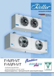
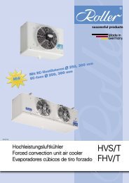
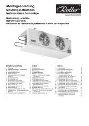
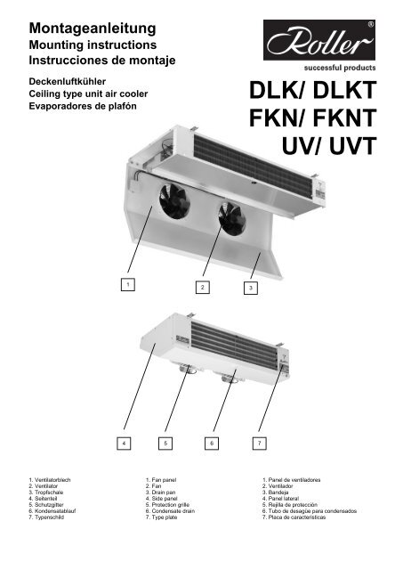
Deckenluftkühler<br />
Ceiling type unit air cooler<br />
Evaporadores de plafón<br />
1. Ventilatorblech<br />
2. Ventilator<br />
3. Tropfschale<br />
4. Seitenteil<br />
5. Schutzgitter<br />
6. Kondensatablauf<br />
7. Typenschild<br />
4<br />
1<br />
1. Fan panel<br />
2. Fan<br />
3. Drain pan<br />
4. Side panel<br />
5. Protection grille<br />
6. <strong>Co</strong>ndensate drain<br />
7. Type plate<br />
2 3<br />
5 6<br />
7<br />
<strong>DLK</strong>/ <strong>DLK</strong>T<br />
<strong>FKN</strong>/ <strong>FKN</strong>T<br />
<strong>UV</strong>/ <strong>UV</strong>T<br />
1. Panel de ventiladores<br />
2. Ventilador<br />
3. Bandeja<br />
4. Panel lateral<br />
5. Rejilla de protección<br />
6. Tubo de desagüe para condensados<br />
7. Placa de caracteristicas
1 Einbauerklärung 1 Declaration of<br />
incorporation<br />
2<br />
Einbauerklärung im Sinne der EG Maschinenrichtlinie 2006/42/EG, Anhang II B<br />
Translation of declaration of incorporation as defined by the EC machinery Directive 2006/42/EC, Annex II B<br />
Traducción de declaración del fabricante según la Directiva de maquinaria CE 2006/42/CE, Anexo II B<br />
Der Hersteller<br />
The manufacturer<br />
<strong>Walter</strong> <strong>Roller</strong> <strong>GmbH</strong> & <strong>Co</strong>.<br />
Lindenstrasse 27- 31<br />
erklärt hiermit, dass die Bauart der<br />
declares hereby that the construction of<br />
El fabricante 70839 Gerlingen, Germany<br />
declara que el modelo de los<br />
Ventilator-Luftkühler/ Forced convection unit air coolers/ Evaporadores de tiro forzado<br />
DHN, <strong>DLK</strong>/T, FHV/T, FHVI/T, <strong>FKN</strong>/T, HVS/T, HVIS/T, SV, <strong>UV</strong>/T, UWD, VW/VM/VD, RDVN, WPV<br />
Ventilatorbelüfteten Verflüssiger/ Forced convection air cooled refrigerant condensers/ <strong>Co</strong>ndensadores frigoríficos axiales<br />
KVN<br />
Ventilator-Konvektoren zur Raumklimatisierung/ Fan coil units for room airconditioning/ Ventilo-convectores para aire acondicionado/<br />
HKN/S/D, HKNI/L, HKNDI/L<br />
die grundlegenden Anforderungen der Maschinenrichtlinie 2006/42/EG erfüllen. Folgende Anforderungen nach<br />
Anhang I der Richtlinie sind angewandt und eingehalten:<br />
meet the basic requirements of the directive of machinery 2006/42/EG. The following requirements according to Annex I are applied and complied.<br />
se cumplen los requisitos fundamentales de la Directiva sobre Maquinaria 2006/42/CE. Los posteriores requisitos del Anexo I de la Directiva se han seguido y<br />
aplicado.<br />
General principe Nr.1.<br />
Nr. 1.3.4, 1.3.7.<br />
Die Inbetriebnahme ist solange untersagt, bis festgestellt wurde, dass die Maschine, in die dieses<br />
Maschinenteil eingebaut werden soll, gegebenenfalls den Bestimmungen der EG Maschinenrichtlinie<br />
2006/42/EG entspricht.<br />
The machine in which the part is incorporated mustn’t be put into service until the conformity of itself according to EC Machinery directive 2006/42/EC has been<br />
declared.<br />
La puesta en servicio está prohibida hasta que esté completamente montada en la parte de la instalación que le corresponde, no siendo declarada hasta entonces<br />
conforme a la Normativa sobre Maquinaria 2006/42/CE.<br />
Die verwendeten Einzelkomponenten sind konform mit den jeweiligen auf sie zutreffenden folgenden weiteren<br />
EG-Richtlinien: 2006/95/EG (Niederspannung), 2004/108/EG (EMV) und 97/23/EG (Druckgeräte).<br />
The incorporated component parts are in conformity with the following additional EC Directives: 2006/95/EC (Low Voltage), 2004/108/EC (EMC) and 97/23/EC<br />
(Pressure Equipment).<br />
Los componentes de construcción incorporados son conformes a las Directivas CE adicionales siguientes: 2006/95/CE (Baja Tensión), 2004/108/CE (CEM) y<br />
97/23/CE (Equipos bajo presión).<br />
Die speziellen technischen Unterlagen nach Anhang VII Teil B wurden vorbereitet.<br />
The special technical files according to annex VII section B have been prepared.<br />
Los datos técnicos especiales han sido establecidos de acuerdo al anexo VII, sección B.<br />
Die Montageanleitung nach Anhang VI wurde verfasst.<br />
The mounting instructions according to annex VI has been written.<br />
Las Instrucciones de montaje se han redactado de acuerdo con el anexo VI.<br />
Montageanleitung und Einbauerklärung sind der unvollständigen Maschine beigelegt.<br />
Mounting instructions and declaration of incorporation are attached to the machine.<br />
Las Instrucciones de montaje y la Declaración del Fabricante se adjuntan con cada aparato.<br />
Einzelstaatlichen Stellen werden auf begründeten Antrag, die speziellen Unterlagen zur unvollständigen<br />
Maschine, innerhalb einer angemessenen Frist übermittelt. Die Dokumente werden auf dem Postweg<br />
zugesandt.<br />
The technical special files will be transmitted to officials by founded claim within in an adequate time. The documents will be sent by mail.<br />
Particularmente para peticiones oficiales se pueden emplear otro tipo de soportes seguros para enviar la información en el caso de pérdida de una parte de la<br />
misma. La documentación puede ser enviada por correo electrónico.<br />
Dokumentationsverantwortlicher ist: Andreas Binder, Lindenstr. 27- 31, 70839 Gerlingen, Deutschland.<br />
Responsible for documentation is: Andreas Binder, Lindenstr. 27- 31, 70839 Gerlingen, Germany.<br />
El responsable de la presente documentación es: Sr. Andreas Binder, Lindenstr. 27- 31, 70839 Gerlingen, Alemania<br />
1 Declaración del<br />
fabricante
Inhaltsverzeichnis<br />
1 Einbauerklärung 2<br />
2 Einleitung 3<br />
3 Sicherheitssymbole 3<br />
4 Sicherheitsvorschriften 4<br />
5 Bestimmungsgemäße Verwendung 5<br />
6 Lagerung 5<br />
7 Transport 5<br />
8 Abmessungen, Rohrinhalte, Gewichte 6<br />
9 Montagevorbereitung <strong>FKN</strong>/T, <strong>UV</strong>/T 9<br />
10 Montage <strong>FKN</strong>/T, <strong>UV</strong>/T 10<br />
11 Montage <strong>DLK</strong>/T 11<br />
12 Anschluss Kältemittel 12<br />
13 Elektroanschluss 13<br />
14 El. Anschlusswerte 13<br />
15 Elektroanschluss Ventilatoren <strong>DLK</strong>/T 14<br />
16 Elektroanschluss Ventilatoren <strong>FKN</strong>/T,<br />
<strong>UV</strong>/T 15<br />
17 Elektroanschluss Heizstäbe <strong>DLK</strong>T und<br />
<strong>UV</strong>T 16<br />
18 Elektroanschluss Heizstäbe <strong>FKN</strong>/T 17<br />
19 Montage Abtausicherheitsthermostat<br />
(Zubehör) 18<br />
20 Anschluss Kondensatablauf 18<br />
21 Montage SI Heizkabel (Zubehör) 19<br />
22 Prüfung vor jeder Inbetriebnahme 20<br />
23 Probelauf, Inbetriebnahme 20<br />
24 Schalldaten 20<br />
25 Reinigung 21<br />
26 Wartungsintervalle 21<br />
27 Entsorgung 21<br />
28 Ersatzteillisten 22<br />
29 Fehlersuche 23<br />
2 Einleitung<br />
Die deutsche Fassung der Montageanleitung<br />
ist das Original.<br />
Alle Sicherheitstexte und Hinweise sind<br />
kursiv gesetzt.<br />
Bewahren Sie diese Montageanleitung auf,<br />
sie ist Teil der Dokumentation der Kälteanlage.<br />
Die jeweils aktuelle Fassung dieser<br />
Montageanleitung kann auf unserer Website<br />
http://www.walterroller.de heruntergeladen<br />
werden.<br />
3 Sicherheitssymbole<br />
Vorsicht!<br />
Bei Nichteinhaltung der Vorschriften<br />
droht Verletzung und Todesgefahr.<br />
Vorsicht!<br />
Bei Nichteinhaltung der Vorschriften<br />
droht durch Hochspannung<br />
Verletzungs- oder Todesgefahr.<br />
Achtung!<br />
Gesetze und Vorschriften müssen<br />
eingehalten werden.<br />
Hinweis<br />
auf sicherheitsgerechten Transport!<br />
Hinweis<br />
auf sicherheitsgerechte Wartung!<br />
Index<br />
1 Declaration of incorporation 2<br />
2 Introduction 3<br />
3 Safety signs 3<br />
4 Safety regulations 4<br />
5 Intended application 5<br />
6 Storage 5<br />
7 Transportation 5<br />
8 Dimensions, tube volumes, weights 6<br />
9 Mounting preparation <strong>FKN</strong>/T, <strong>UV</strong>/T 9<br />
10 Mounting <strong>FKN</strong>/T, <strong>UV</strong>/T 10<br />
11 Mounting <strong>DLK</strong>/T 11<br />
12 Refrigerant connection 12<br />
13 Electric connection 13<br />
14 Electrical loads 13<br />
15 Electric connection fans <strong>DLK</strong>/T 14<br />
16 Electric connection fans <strong>FKN</strong>/T, <strong>UV</strong>/T 15<br />
17 Electric connection heater rods<br />
<strong>DLK</strong>T and <strong>UV</strong>T 16<br />
18 Electric connection heater rods <strong>FKN</strong>T 17<br />
19 Mounting of the defrost safety thermostat<br />
(accessory) 18<br />
20 <strong>Co</strong>nnection condensate drain 18<br />
21 Mounting of the SI- flexible heater 230 V<br />
(accessory) 19<br />
22 Check- up before each start- up 20<br />
23 Test- run, start- up 20<br />
24 Sound pressure levels 20<br />
25 Cleaning 21<br />
26 Service interval 21<br />
27 Disposal 21<br />
28 Spare parts 22<br />
29 Trouble- shooting 23<br />
2 Introduction<br />
This mounting instruction is a translation of<br />
the german original Montageanleitung.<br />
All safety information and advice is printed<br />
in italics.<br />
Keep these instructions; they are part of the<br />
refrigerating plant.<br />
You can download the latest revision of<br />
these mounting instructions on our website<br />
http://www.walterroller.com.<br />
3 Safety signs<br />
Caution!<br />
Risk of injury or peril to life if<br />
instructions aren’t followed.<br />
Caution!<br />
Risk of injury or peril to life from<br />
high voltage if instructions aren’t<br />
followed.<br />
Attention!<br />
Laws and regulations have to be<br />
obeyed.<br />
Advice<br />
for safe transport!<br />
Advice<br />
for safe servicing!<br />
Ìndice<br />
1 Declaración del fabricante 2<br />
2 Introducción 3<br />
3 Símbolos de seguridad 3<br />
4 <strong>Co</strong>nsignas de seguridad 4<br />
5 Modos de empleo 5<br />
6 Almacenamiento 5<br />
7 Transporte 5<br />
8 Dimensiones, capacidad de los tubos y<br />
pesos 6<br />
9 Preparación montaje <strong>FKN</strong>/T, <strong>UV</strong>/T 9<br />
10 Montaje <strong>FKN</strong>/T, <strong>UV</strong>/T 10<br />
11 Montaje <strong>DLK</strong>/T 11<br />
12 <strong>Co</strong>nexiones de refrigerante 12<br />
13 <strong>Co</strong>nexión eléctrica 13<br />
14 Características eléctricas 13<br />
15 <strong>Co</strong>nexión el. de los ventiladores <strong>DLK</strong>/T 14<br />
16 ″ ″ ″ ″ ″ <strong>FKN</strong>/T, <strong>UV</strong>/T 15<br />
17 <strong>Co</strong>nexión eléctrica de las resistencias<br />
<strong>DLK</strong>T y <strong>UV</strong>T 16<br />
18 ″ ″ ″ ″ “ <strong>FKN</strong>T 17<br />
19 Montaje del termostato de seguridad de<br />
desescarche (accesorio) 18<br />
20 <strong>Co</strong>nexión desagüe para condensados 18<br />
21 Montaje de la resistencia SI 19<br />
22 Verificaciones antes de<br />
la puesta en marcha 20<br />
23 Primer arranque, puesta en marcha 20<br />
24 Presión sonora 20<br />
25 Limpieza 21<br />
26 Revisión técnica 21<br />
27 Fin del periodo útil del evaporador 21<br />
28 Piezas de repuesto 22<br />
29 Diagnóstico de fallos 23<br />
2 Introducción<br />
Estas Instrucciones de Montaje han sido<br />
traducidas del original en Alemán<br />
Montageanleitung.<br />
Las indicaciones e instrucciones de<br />
seguridad se han escrito en letra cursiva.<br />
<strong>Co</strong>nserve estas instrucciones, son parte<br />
de la información técnica de la instalación<br />
frigorífica.<br />
Puede Vd. descargar la última edición de<br />
estas instrucciones de montaje en nuestra<br />
página web: http://www.walterroller.com.<br />
3 Símbolos de seguridad<br />
¡Atención!<br />
No respetar las indicaciones de<br />
peligro puede causar lesiones o ser<br />
mortal.<br />
¡Atención!<br />
Alta tensión. No respetar las<br />
indicaciones de peligro puede<br />
causar lesiones o ser mortal.<br />
¡Atención!<br />
Las indicaciones y la legislación<br />
deben ser respetadas.<br />
Indicaciones<br />
¡Sobre las directivas de transporte<br />
conforme a las reglas de<br />
seguridad!<br />
Indicaciones<br />
¡Sobre las directivas de<br />
mantenmiento conforme a las<br />
reglas de seguridad!<br />
3
4 Sicherheitsvorschriften<br />
1.Vorschriften<br />
Bei der Montage und Inbetriebnahme sind<br />
alle Sicherheits- und Unfallverhütungsvorschriften<br />
sowie die Richtlinien und<br />
Normen im Einbauland zu beachten.<br />
2. Persönliche<br />
Voraussetzungen<br />
Die Anlage darf nur von autorisiertem und<br />
qualifiziertem Fachpersonal montiert und<br />
gewartet werden.<br />
Der Elektroanschluss darf nur von einer<br />
Elektrofachkraft gemäß den elektrotechnischen<br />
Regeln vorgenommen werden.<br />
Als qualifiziertes Fachpersonal gilt, wer mit<br />
dem beschriebenen Produkt vertraut ist und<br />
auf Grund seiner fachlichen Ausbildung,<br />
Kenntnisse und Erfahrungen sowie Kenntnis<br />
der einschlägigen Bestimmungen, die ihm<br />
übertragenen Arbeiten beurteilen und<br />
mögliche Gefahren erkennen kann.<br />
3. Persönliche<br />
Schutzausrüstung<br />
Die Schutzausrüstung bei Montage und<br />
Wartung muss den sicherheitstechnischen<br />
Vorschriften entsprechen. Lose oder<br />
herunterhängende Kleidungsstücke, oder<br />
lange Haare können sich bei Arbeiten im<br />
Gerät verfangen.<br />
4. Unfallschutz<br />
Bei Montage, Wartung und Reparatur<br />
muss der Gefahrenbereich für unbefugte<br />
Personen, insbesondere Kinder, weiträumig<br />
abgesichert werden.<br />
Vor allen Arbeiten an der Anlage Strom<br />
abschalten und gegen unbefugtes<br />
Einschalten sichern.<br />
Vorsicht an Wänden und Decken in denen<br />
Strom-, Gas- und Wasserleitungen verlegt<br />
sein könnten.<br />
5. Eigenmächtige Umbauten<br />
Umbauten und Veränderungen an der<br />
Anlage sind nicht gestattet.<br />
6. Sicherheit<br />
Nach dem Einbau in die Kälteanlage<br />
müssen die vom Gerät ausgehenden<br />
Sicherheitsrisiken nochmals bewertet<br />
werden.<br />
Achtung!<br />
Bei Nichteinhaltung der<br />
Vorschriften droht Gefahr für<br />
Leib und Leben.<br />
4<br />
4 Safety regulations<br />
1. Regulations<br />
During installation and start-up, all<br />
regulations for safety and accident<br />
prevention as well as rules and standards of<br />
the individual country have to be observed.<br />
2. Personal<br />
qualification<br />
The unit may only be mounted and<br />
serviced by authorized and skilled<br />
personnel.<br />
The electrical connection may only be<br />
made by a licensed electrician according to<br />
the electro technical regulations.<br />
Skilled personal is who is familiar with the<br />
described product and is able to recognize<br />
possible dangers at the assigned tasks<br />
because of his professional education,<br />
experience and knowledge of the relevant<br />
regulations.<br />
3. Personal protective<br />
equipment<br />
The protective equipment for mounting and<br />
servicing has to comply with the security<br />
regulations. Loose or down- hanging clothes<br />
or long hair can be caught up in the unit<br />
during works.<br />
4. Accident prevention<br />
During mounting, servicing and repairing<br />
the danger area has to be guarded safely<br />
from unauthorized persons, especially<br />
children.<br />
Prior to working on the unit, switch- off<br />
electricity and secure against unauthorized<br />
connecting.<br />
Be careful with walls and ceilings which<br />
could possibly contain electric wires or gas<br />
and water piping.<br />
5. Unauthorized<br />
modification<br />
Modifications and alterations on the unit<br />
are not allowed.<br />
6. Safety<br />
After the incorporation into the refrigeration<br />
plant the safety risks of the unit have to be<br />
rerated.<br />
Attention!<br />
Not observing regulations means<br />
danger for life and limb.<br />
4 <strong>Co</strong>nsignas de seguridad<br />
1. Prescripciones<br />
El montaje y la puesta en marcha están<br />
sometidos a las consignas de seguridad y a las<br />
prescripciones de prevención de accidentes, lo<br />
mismo que a las directivas del país donde se<br />
realice la puesta en marcha.<br />
2. Calificación<br />
del personal<br />
La unidad sólo debe ser instalada y<br />
mantenida por personal autorizado.<br />
El conexionado eléctrico sólo debe ser<br />
efectuado por un técnico cualificado conforme<br />
a las normas electrotécnicas.<br />
El personal técnico cualificado es quién está<br />
familiarizado con el producto descrito y es<br />
capaz de reconocer los posibles peligros de las<br />
tareas asignadas debido a su formación<br />
profesional, experiencia y conocimiento.<br />
3. Equipo de<br />
protección personal<br />
El equipo de protección durante el montaje y<br />
el mantenimiento debe ser conforme a las<br />
prescripciones de seguridad técnica. Ponga<br />
especial atención durante los trabajos con el<br />
evaporador en caso de utilizar ropas muy flojas<br />
o tiene el pelo largo y sin recoger.<br />
4. Prevención de<br />
accidentes<br />
Durante el montaje, mantenimiento o<br />
reparación, las personas no autorizadas, en<br />
particular los menores, deben mantenerse<br />
fuera del alcance de la zona de peligro.<br />
Desconecte la unidad antes de cada<br />
intervención, asegurándose que no se pueda<br />
conectar por personal no autorizado.<br />
Asegúrese que los muros y paredes no<br />
contengan conducciones eléctricas, de gas o<br />
de agua.<br />
5. Modificaciones<br />
arbitrarias<br />
Las modificaciones y cambios en la unidad<br />
no están autorizados.<br />
6. Seguridad<br />
Después del montaje en la instalación<br />
frigorífica se deberán volver a leer los capítulos<br />
de seguridad y riesgo.<br />
¡Atención!<br />
La no observancia de las<br />
instrucciones concernientes a la<br />
instalación amenaza su persona<br />
física y su vida.
5 Bestimmungsgemäße<br />
Verwendung<br />
Die bestimmungsgemäße Verwendung des<br />
Luftkühlers besteht im Abkühlen bzw. Erhitzen<br />
und Fördern von feuchter Luft. Ebenso<br />
umfasst die bestimmungsgemäße<br />
Verwendung des Luftkühlers das<br />
gegebenenfalls nötige Abtauen und das<br />
Ableiten des anfallenden Kondensates.<br />
Die Montage und der Anschluss müssen<br />
nach dieser Anleitung erfolgen.<br />
Die Deckenluftkühler <strong>DLK</strong>/ T, <strong>FKN</strong>/T und<br />
<strong>UV</strong>/T dürfen nur in technisch einwandfreiem<br />
Zustand, mit einer technisch einwandfreien<br />
Kälteanlage betrieben werden.<br />
Die Anlage ist für alle Kältemittel der<br />
Sicherheitsgruppe A1 nach EN 378-1<br />
geeignet. Diese Kältemittel sind in der<br />
Druckgeräterichtlinie der Gruppe 2<br />
zugeordnet.<br />
Zulässiger Betriebsdruck PS siehe<br />
Typenschild.<br />
Die auf dem Typenschild angegebenen<br />
Umgebungstemperaturbereiche sind<br />
einzuhalten.<br />
(Position des Typenschildes siehe Frontseite)<br />
Beachten Sie auch den gesonderten<br />
Temperatureinsatzbereich des Ventilators.<br />
Folgende Luftverunreinigungen sind zu<br />
meiden:<br />
o Abrasive (abtragende) Partikel.<br />
o Stark korrosiv wirkende Verunreinigungen<br />
z.B. Salznebel.<br />
o Hohe Staubbelastung z.B. Absaugung<br />
von Sägespänen.<br />
o Brennbare Gase/ Partikel.<br />
Der Kühler darf nicht in der Nähe von<br />
brennbaren Stoffen und Komponenten<br />
betrieben werden.<br />
Der Kühler darf nicht in explosiver<br />
Atmosphäre betrieben werden.<br />
Der Kühler darf keine sicherheitsrelevanten<br />
Aufgaben übernehmen.<br />
Alle nicht bestimmungsgemäßen<br />
Verwendungen sind verboten.<br />
6 Lagerung<br />
Anlage bis zur Montage trocken und<br />
wettergeschützt in der Originalverpackung<br />
lagern.<br />
7 Transport<br />
Zum Transport sollte die Original-<br />
verpackung verwendet werden.<br />
Nur an den vorgesehenen<br />
Transportvorrichtungen mit geeignetem<br />
Hebezeug transportieren.<br />
Gewichtangabe siehe Kapitel 8.<br />
Anlage vorsichtig transportieren, Schläge<br />
und Stöße vermeiden.<br />
5 Intended application<br />
The intended application of the air cooler is<br />
the cooling or heating and blowing of humid<br />
air. A defrost operation and the drain of the<br />
condensate is intended application, too.<br />
Mounting and connecting has to be done<br />
according to these instructions.<br />
The ceiling type unit air cooler <strong>DLK</strong>/T,<br />
<strong>FKN</strong>/T and <strong>UV</strong>/T may only be operated in<br />
excellent technical condition with a technical<br />
sound refrigerating plant.<br />
The unit is suitable for all refrigerants of<br />
safety group A1 according to EN 378-1.<br />
These refrigerants are assigned to group 2 in<br />
the Pressure Equipment Directive (PED).<br />
Allowable operating pressure PS see type<br />
plate.<br />
The ambient temperature ranges given on<br />
the type plate have to be maintained.<br />
(Position of the type plate see front page)<br />
<strong>Co</strong>nsider the different operating conditions<br />
of the fan.<br />
The following pollutions of the air have to be<br />
avoided:<br />
o Abrasive particles.<br />
o Strong corrosive pollutions e.g. salt spray<br />
mist.<br />
o High dust loading, e.g. exhaustion of saw<br />
dust.<br />
o Flammable gases/ particles.<br />
The cooler may not be run next to<br />
flammable materials or components.<br />
The cooler may not be run in explosive<br />
ambient.<br />
The cooler mustn’t take over security<br />
relevant duties.<br />
Use for purpose other than designed for is<br />
forbidden.<br />
6 Storage<br />
The unit has to be warehoused dry and<br />
weather protected in the original packing until<br />
installation.<br />
7 Shipping<br />
The original packing should be used for<br />
transport.<br />
Should only be moved with intended lifting<br />
device using appropriate fixtures. For weight<br />
specifications see chapter 8.<br />
Move the unit carefully avoiding jolts and<br />
impacts.<br />
5 Modos de empleo<br />
Este aparato está indicado para funciones<br />
de refrigeración ó calefacción y regulación<br />
de la humedad del aire. El sistema de<br />
desescarche y la bandeja de condensados<br />
complementan las tareas derivadas de las<br />
funciones descritas.<br />
El montaje y el conexionado se deben<br />
efectuar conforme a las instrucciones del<br />
manual de uso.<br />
El evaporador de plafón <strong>DLK</strong>/T, <strong>FKN</strong>/T y<br />
<strong>UV</strong>/T se debe de encontrar en un estado<br />
de funcionamiento irreprochable, con una<br />
instalación frigorífica que se encontrará<br />
igualmente en el mismo estado.<br />
La unidad se ha previsto para funcionar<br />
con fluidos frigoríficos del Grupo de<br />
Seguridad A1 según la EN 378-1. Estos<br />
refrigerantes están asignados al grupo 2 en<br />
el Reglamento de Aparatos a Presión<br />
(RAP).<br />
Máxima presión de servicio admisible PS<br />
ver en la placa de características.<br />
Los rangos de temperatura ambiente se<br />
indican en la placa de características.<br />
(Posición de la placa en la primera página).<br />
<strong>Co</strong>mprobar las condiciones de<br />
funcionamiento del ventilador.<br />
Se debe evitar aire conteniendo las<br />
siguientes sustancias contaminantes:<br />
o Partículas abrasivas.<br />
o Sustancias altamente corrosivas, por<br />
ejemplo ambientes salinos.<br />
o Altas concentraciones de polvo, por<br />
ejemplo serrín.<br />
o Gases o partículas inflamables,<br />
Este evaporador no está preparado para<br />
funcionar con materias o componentes<br />
inflamables.<br />
Este evaporador no está preparado para<br />
funcionar en ambientes explosivos.<br />
Este evaporador no puede asumir tareas<br />
en condiciones de seguridades relevantes.<br />
Todos los usos que no respeten los<br />
modos de empleo están prohibidas.<br />
6 Almacenamiento<br />
La unidad se debe almacenar en lugar<br />
seco y protegido de la intemperie, en su<br />
embalaje original hasta el momento del<br />
montaje.<br />
7 Transporte<br />
Para efectuar el transporte se debe utilizar<br />
el embalaje original.<br />
Transportar únicamente con los medios<br />
adecuados y en los puntos de transporte<br />
previstos para este efecto. Especificaciones<br />
de pesos: ver capítulo 8.<br />
Transporte la unidad con prudencia,<br />
evitando choques y golpes.<br />
5
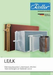
8 Abmessungen,<br />
Rohrinhalte, Gewichte<br />
6<br />
Typ<br />
Model<br />
Modelo<br />
8 Dimensions,<br />
tube volumes, weights<br />
Abmessungen in mm<br />
Dimension in mm<br />
Dimensiones en mm<br />
Rohrinhalte<br />
Tube volumes<br />
Volumen interno<br />
8 Dimensiones, capacidad<br />
de los tubos y pesos<br />
Gewichte<br />
Weights<br />
Pesos<br />
<strong>DLK</strong> <strong>DLK</strong>T<br />
<strong>DLK</strong> / <strong>DLK</strong>T 4.. 6../ 7.. 4.. 6../ 7..<br />
A B C D dm³ kg kg kg kg<br />
401 EC 601 EC 701 EC 660 420 - - 0,9 11 10 12 11<br />
411 EC 611 EC 711 EC 660 420 - - 1,2 12 11 13 12<br />
421 EC 621 EC 721 EC 860 620 - - 1,3 13 12 14 13<br />
431 EC 631 EC 731 EC 860 620 - - 1,9 14 13 15 14<br />
412 EC 612 EC 712 EC 1062 822 - - 2,4 20 18 22 20<br />
432 EC 632 EC 732 EC 1462 1222 - - 3,4 25 23 27 25<br />
413 EC 613 EC 713 EC 1462 1223 - - 3,6 28 25 31 28<br />
433 EC 633 EC 733 EC 2063 1823 - - 5,8 36 33 39 36<br />
414 EC 614 EC 714 EC 1865 1625 - - 4,8 36 32 40 36<br />
434 EC 634 EC 734 EC 2665 2426 1223 1202 7,7 47 43 51 47
Typ<br />
Model<br />
Modelo<br />
<strong>DLK</strong>/ <strong>DLK</strong>T<br />
Abmessungen in mm<br />
Dimension in mm<br />
Dimensiones en mm<br />
Rohrinhalte<br />
Tube volumes<br />
Volumen interno<br />
Gewichte<br />
Weights<br />
Pesos<br />
<strong>DLK</strong> <strong>DLK</strong>T<br />
4.. 7.. 10.. 4.. 7.. 10..<br />
A B C D dm³ kg kg kg kg kg kg<br />
441 EC 741 EC 1041 EC 915 620 - - 1,9 18 17 16 20 19 18<br />
461 EC 761 EC 1061 EC 915 620 - - 2,9 22 20 18 24 22 20<br />
442 EC 742 EC 1042 EC 1515 1222 - - 3,5 32 29 26 35 32 29<br />
462 EC 762 EC 1062 EC 1515 1222 - - 5,4 39 35 31 42 38 34<br />
443 EC 743 EC 1043 EC 2117 1823 620 1203 5,2 45 41 37 48 44 40<br />
463 EC 763 EC 1063 EC 2117 1823 620 1203 7,8 56 50 44 59 53 47<br />
444 EC 744 EC 1044 EC 2718 2425 1 222 1203 6,8 60 54 48 64 58 52<br />
464 EC 764 EC 1064 EC 2718 2425 1 222 1203 10,3 73 65 57 77 69 61<br />
7
<strong>FKN</strong>/T flatline <strong>FKN</strong>/T flatline <strong>FKN</strong>/T flatline<br />
<strong>UV</strong>/T Euroline <strong>UV</strong>/T Euroline <strong>UV</strong>/T Euroline<br />
8<br />
Typ<br />
Model<br />
Modelo<br />
Abmessungen in mm<br />
Dimensions in mm<br />
Dimensiones en mm<br />
Rohrinhalt<br />
Tube volume<br />
Volumen interno<br />
Gewicht<br />
Weight<br />
Pesos<br />
<strong>FKN</strong> <strong>FKN</strong>T <strong>FKN</strong> <strong>FKN</strong>T<br />
A B dm³ kg kg<br />
411 611 450 300 0,4 5 6<br />
412 612 450 300 0,6 6 7<br />
423 623 750 600 0,7 9 10<br />
424 624 750 600 1,0 10 11<br />
436 636 1050 900 1,4 14 15<br />
Typ Abmessungen in mm Rohrinhalte Gewichte<br />
Model Dimensions in mm Tube volumes Weights<br />
Modelo Dimensiones en mm Volumen interno Pesos<br />
<strong>UV</strong> 4.. EC <strong>UV</strong>T 4.. EC <strong>UV</strong> 6.. EC <strong>UV</strong>T 6.. EC<br />
<strong>UV</strong>/T A B C dm³ kg kg kg kg<br />
410 EC 610 EC 610 400 - 0,9 7 8 7 8<br />
415 EC 615 EC 1010 800 - 1,6 11 12 11 12<br />
420 EC 620 EC 1010 800 - 1,6 13 14 12 13<br />
425 EC 625 EC 1410 1200 - 2,6 17 19 16 18<br />
430 EC 630 EC 1410 1200 - 2,6 19 20 18 19<br />
440 EC 640 EC 1810 1600 B/2 3,4 24 26 23 25
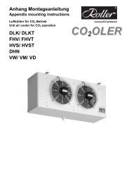
9 Montagevorbereitung<br />
<strong>FKN</strong>/T, <strong>UV</strong>/T<br />
Die Anlage darf nur von autorisiertem<br />
Fachpersonal montiert werden.<br />
1. Auspacken.<br />
2. Ventilatorblech abnehmen und<br />
Rohrverschlüsse entfernen.<br />
3. Der Lamellenblock ist zur Montage des<br />
Expansionsventils herausnehmbar (<strong>FKN</strong>/T).<br />
4. Expansionsventil nach dessen<br />
Montageanleitung montieren.<br />
Achten Sie auf ausreichenden<br />
Sicherheitsabstand zum Ventilator.<br />
Typ<br />
Model<br />
Modelo<br />
Eintritt<br />
Inlet<br />
Entrada<br />
Austritt<br />
Outlet<br />
Salida<br />
<strong>FKN</strong> <strong>FKN</strong>T Ø mm Ø mm<br />
411 611 10 10<br />
412 612 10 10<br />
423 623 10 10<br />
424 624 10 10<br />
436 636 12* 15<br />
<strong>UV</strong>/ <strong>UV</strong>T Euroline<br />
410 EC 610 EC 12 12<br />
415 EC 615 EC 12 12<br />
420 EC 620 EC 12 12<br />
425 EC 625 EC 12* 15<br />
430 EC 630 EC 12* 15<br />
440 EC 640 EC 12* 15<br />
9 Mounting preparation<br />
<strong>FKN</strong>/T, <strong>UV</strong>/T<br />
The unit may only be installed by<br />
authorized and skilled personnel.<br />
1. Unpack.<br />
2. Remove fan panel and remove the pipe<br />
plugs.<br />
3. The fin block can be unhinged to mount<br />
the expansion valve (<strong>FKN</strong>/T).<br />
4. Mount the expansion valve according to<br />
its mounting instructions.<br />
Keep in mind that there is enough security<br />
space to the fan.<br />
* Mehrfacheinspritzung mit Schraderventil am Austritt<br />
* Multiple injection with Schrader valve at the outlet<br />
* Inyección múltiple a la salida de la válvula<br />
9 Preparación para el<br />
montaje <strong>FKN</strong>/T, <strong>UV</strong>/T<br />
La unidad deberá ser instalada sólo por<br />
personal autorizado.<br />
1. Desembalar.<br />
2. Desmontar la bandeja del ventilador y<br />
quitar los capuchones de los tubos<br />
3. Se puede extraer la batería para<br />
proceder a montar la válvula de expansión<br />
(<strong>FKN</strong>/T).<br />
4. Instale la válvula de expansión tal como<br />
se indica en estas instrucciones.<br />
Deje espacio suficiente hasta el ventilador.<br />
9
10 Montage <strong>FKN</strong>/T, <strong>UV</strong>/T<br />
Die Anlage darf nur von autorisiertem<br />
Fachpersonal montiert werden.<br />
Stellen Sie sicher, dass das Bauwerk den<br />
durch den Luftkühler hervorgerufenen<br />
statischen und dynamischen Belastungen<br />
genügt.<br />
1. Deckenmontage.<br />
2. Wandanordnung mit zusätzlicher<br />
Tropfschale (Zubehör).<br />
Bohrschablone auf der Verpackung kann<br />
verwendet werden.<br />
3. Wandmontage mit Konsolen (Zubehör).<br />
10<br />
Maß B siehe S. 8.<br />
1.<br />
2.<br />
10 Mounting <strong>FKN</strong>/T, <strong>UV</strong>/T<br />
The unit may only be mounted by<br />
authorized and skilled personnel!<br />
Assure that the building fits the static and<br />
dynamic stresses caused by the air cooler.<br />
1. Ceiling mounting.<br />
2. Wall version with additional drip tray<br />
(accessory).<br />
Drill pattern on the packing can be used.<br />
3. Wall mounting with brackets (accessory).<br />
Dimension B, see page 8.<br />
3.<br />
10 Montaje <strong>FKN</strong>/T, <strong>UV</strong>/T<br />
La unidad deberá ser instalada solo por<br />
personal autorizado!<br />
Asegúrese de realizar el montaje del<br />
evaporador con elementos que eviten cargas<br />
estáticas ó dinámicas en el mismo.<br />
1. Montaje de plafón.<br />
2. Versión mural con una bandeja<br />
suplementaria (accesorio).<br />
Se puede utilizar la plantilla suministrada<br />
en el embalaje<br />
3. Montaje mural con soportes (accesorio).<br />
Para saber la cota B, ver pagina 8.
11 Montage <strong>DLK</strong>/T<br />
Die Anlage darf nur von autorisiertem<br />
Fachpersonal montiert werden.<br />
Stellen Sie sicher, dass das Bauwerk den<br />
durch den Luftkühler hervorgerufenen<br />
statischen und dynamischen Belastungen<br />
genügt.<br />
Bei der Montage alle<br />
Befestigungspunkte verwenden.<br />
1. Auspacken.<br />
2. Deckenmontage/<br />
Wandmontage mit zusätzlicher Tropfschale.<br />
Maße siehe Seite 6- 7. Bitte<br />
Mindestabstand A - 100 mm zum<br />
Austausch der Heizstäbe beachten.<br />
11 Mounting <strong>DLK</strong>/T<br />
The unit may only be installed by<br />
authorized and skilled personnel.<br />
Assure that the building fits the static and<br />
dynamic stresses caused by the air cooler.<br />
When installing, use all the provided<br />
mounting points.<br />
1. Unpack.<br />
2. Ceiling Mounting/<br />
Wall mounting with additional drip tray.<br />
Dimensions see page 6- 7.<br />
At <strong>DLK</strong>/T please bear in mind a minimum<br />
space A - 100 mm for replacing headers!<br />
11 Montaje <strong>DLK</strong>/T<br />
La unidad deberá ser instalada sólo por<br />
personal autorizado.<br />
Asegúrese de realizar el montaje del<br />
evaporador con elementos que eviten cargas<br />
estáticas ó dinámicas en el mismo.<br />
¡Para el montaje, utilizar todos los<br />
puntos de fijación!<br />
1. Desembalar.<br />
2. Montaje de plafón/<br />
Montaje mural con una bandeja<br />
suplementaria.<br />
Dimensiones ver página 6- 7.<br />
¡Para <strong>DLK</strong>/T asegúrese que la distancia<br />
A - 100 mm para sustituir las resistencias!<br />
11
12 Anschluss Kältemittel<br />
Die Anlage ist für alle Kältemittel der<br />
Sicherheitsgruppe A2 nach EN 378-1 geeignet.<br />
Diese Kältemittel sind in der<br />
Druckgeräterichtlinie der Gruppe 2 zugeordnet.<br />
Beachten Sie bei <strong>UV</strong>/T und <strong>FKN</strong>/T die Kapitel<br />
9 und 10 und fahren Sie nach Punkt 2. / 3. in<br />
diesem Kapitel fort.<br />
1. Seitenteil (<strong>DLK</strong>/T) abnehmen und<br />
Rohrverschlüsse abnehmen.<br />
2. / 3. Expansionsventil nach dessen<br />
Montageanleitung montieren.<br />
12<br />
Verteilerrohre nicht knicken.<br />
Kältemittelrohrleitung fachgerecht<br />
anschließen.<br />
Kältemittel- Rohrleitungen mit genügend<br />
Sicherheitsabstand zu den Heizstäben<br />
verlegen!<br />
Bei <strong>UV</strong>/T und <strong>FKN</strong>/T Kältemittel- Rohrleitung<br />
so legen, dass keine Berührung mit den<br />
Ventilatorflügeln entstehen kann.<br />
4. Seitenteil (<strong>DLK</strong>/T) bzw. Ventilatorblech<br />
(<strong>UV</strong>/T, <strong>FKN</strong>/T) montieren.<br />
Typ Eintritt Austritt<br />
Model Inlet Outlet<br />
Modelo Entrada Salida<br />
<strong>DLK</strong>/ <strong>DLK</strong>T Ø mm Ø mm<br />
401 EC 601 EC 701 EC 12 12<br />
411 EC 611 EC 711 EC 12 12<br />
421 EC 621 EC 721 EC 12 12<br />
431 EC 631 EC 731 EC 12 12<br />
412 EC 612 EC 712 EC 12* 18<br />
432 EC 632 EC 732 EC 12* 18<br />
413 EC 613 EC 713 EC 12* 18<br />
433 EC 633 EC 733 EC 12* 22<br />
414 EC 614 EC 714 EC 12* 22<br />
434 EC 634 EC 734 EC 12* 22<br />
<strong>DLK</strong> / <strong>DLK</strong>T<br />
441 EC 741 EC 1041 EC 12 15<br />
461 EC 761 EC 1061 EC 12 15<br />
442 EC 742 EC 1042 EC 12 15<br />
462 EC 762 EC 1062 EC 12* 22<br />
443 EC 743 EC 1043 EC 12* 22<br />
463 EC 763 EC 1063 EC 12* 22<br />
444 EC 744 EC 1044 EC 12* 22<br />
464 EC 764 EC 1064 EC 12* 28<br />
* Mehrfacheinspritzung mit Schraderventil am Austritt<br />
* Multiple injection with Schrader valve at the outlet<br />
* Inyección múltiple a la salida de la válvula<br />
12 Refrigerant connection<br />
The unit is suitable for all refrigerants of the<br />
safety group A1 according to EN 378-1.<br />
These refrigerants are assigned to group 2<br />
in Pressure Equipment Directive (PED).<br />
When mounting <strong>UV</strong>/T and <strong>FKN</strong>/T pay<br />
attention to the chapters 9 and 10 and<br />
continue after point of these 2. / 3. chapter.<br />
1. Remove side panel (<strong>DLK</strong>/T) and tube<br />
seals.<br />
2. / 3. Fit the expansion valve observing its<br />
mounting instruction.<br />
Don’t bend or buckle the distributor tubes.<br />
<strong>Co</strong>nnect the refrigerant piping properly.<br />
Mount the refrigerant piping with enough<br />
safety distance to the heater rods.<br />
At <strong>UV</strong>/T and <strong>FKN</strong>/T mount the refrigerant<br />
pipes in a way, that they don’t get into<br />
contact with the fan blades.<br />
4. Fit the side panel (<strong>DLK</strong>/T) resp. the fan<br />
sheet (<strong>UV</strong>/T, <strong>FKN</strong>/T)<br />
12 <strong>Co</strong>nexiones de<br />
refrigerante<br />
La unidad se ha previsto para funcionar con<br />
fluidos frigoríficos del Grupo de Seguridad A1<br />
según la EN 378-1. Estos refrigerantes están<br />
asignados al grupo 2 en el Reglamento de<br />
Aparatos a Presion (RAP).<br />
Para la instalación de los <strong>UV</strong>/T y <strong>FKN</strong>/T, lea<br />
primero los puntos 9 y 10, volviendo a<br />
continuación a los puntos 2./ 3. .<br />
1. Sacar la parte lateral (<strong>DLK</strong>/T) y quitar los<br />
capuchones de los tubos.<br />
2. / 3. Montar la válvula de expansión según<br />
las instrucciones de montaje.<br />
No deformar las tuberías del distribuidor.<br />
Abocardar la tubería correctamente.<br />
Monte la tubería de fluido frigorífico con una<br />
separación suficiente de las resistencias!<br />
Para <strong>UV</strong>/T y <strong>FKN</strong>/T monte las tuberías de<br />
fluido refrigerante de manera que nunca<br />
puedan ser alcanzadas por las hélices del<br />
ventilador.<br />
4. Montar nuevamente la tapa lateral (<strong>DLK</strong>/T)<br />
y el panel de ventil. (<strong>UV</strong>/T, <strong>FKN</strong>/T)<br />
respectivamente.
13 Elektroanschluss<br />
Zuleitung mit genügend Sicherheitsabstand<br />
zum rotierenden Ventilator verlegen!<br />
Bringen Sie immer einen Schutzleiter an.<br />
Schließen Sie den Kühler nur an<br />
Stromkreise an, die mit einem allpolig<br />
trennenden Schalter abschaltbar sind.<br />
Verwenden Sie nur Leitungen, die den<br />
vorgeschriebenen Installationsvorschriften<br />
hinsichtlich Spannung, Strom,<br />
Isolationsmaterial, Belastbarkeit etc.<br />
entsprechen.<br />
Lose Verbindungen und defekte Kabel sofort<br />
ersetzen.<br />
Das Gerät erst 5 Minuten nach dem<br />
allpoligen Abschalten der Spannung öffnen.<br />
Beim Arbeiten am Gerät auf eine<br />
Gummimatte stellen.<br />
13 Electric connection<br />
Mount supply wire with enough safety<br />
disctance to the fans.<br />
Always mount the protective earth<br />
conductor!<br />
Mount the unit only to circuits that are<br />
equipped with circuit breaker.<br />
Use only wires that are in conformity to<br />
installation rules in case of voltage, current,<br />
insulation materials, capacity, etc.<br />
Replace loose connections and defective<br />
cable immediately.<br />
Don’t open the unit till 5 minutes after<br />
switching off the power supply.<br />
If working on the unit stand on a rubber mat.<br />
13 <strong>Co</strong>nexión eléctrica<br />
¡Realice el cableado adicional manteniendo<br />
suficiente distancia de seguridad a los<br />
ventiladores!<br />
Instale siempre un cable conductor a tierra<br />
La unidad se alimentará con una línea<br />
exclusiva equipada con interruptor de corte<br />
Utilice solamente mangueras eléctricas que<br />
cumplan la normativa eléctrica de voltaje,<br />
intensidad, aislamiento, capacidad, etc.<br />
Reemplace inmediatamente las conexiones<br />
flojas ó cables defectuosos.<br />
No abra la unidad hasta que hayan<br />
transcurrido 5 minutos desde el corte del<br />
suministro eléctrico.<br />
Para trabajar en el aparato, aislarse del<br />
suelo mediante una alfombrilla de goma.<br />
14 El. Anschlusswerte 14 Electric loads 14 Características eléctricas<br />
Typ<br />
Model<br />
Modelo<br />
<strong>DLK</strong> / <strong>DLK</strong>T<br />
Anzahl x Ø<br />
Number x Ø<br />
Número x Ø<br />
Leistung<br />
Input cap.<br />
Potencia<br />
Nennleistung ~ 230 V 50/ 60 Hz<br />
Capacity rating ~ 230 V 50/ 60 Hz<br />
Potencia ~ 230 V 50/ 60 Hz<br />
Stromaufn.<br />
Curr. <strong>Co</strong>ns.<br />
Intensidad<br />
Drehzahl<br />
r.p.m.<br />
r.p.m.<br />
Block<br />
<strong>Co</strong>il<br />
Batería<br />
Elektrische Abtauheizung <strong>DLK</strong>T<br />
Electric defrost <strong>DLK</strong>T<br />
Desescarche eléctrico <strong>DLK</strong>T<br />
Schale<br />
Drain pan<br />
Bandeja<br />
mm W A min -1 W W W<br />
401 EC 601 EC 701 EC 1 x 250 31 0,24 1400 1 x 400 1 x 400 800<br />
411 EC 611 EC 711 EC 1 x 250 31 0,24 1400 1 x 400 1 x 400 800<br />
421 EC 621 EC 721 EC 1 x 250 31 0,24 1400 1 x 550 1 x 550 1100<br />
431 EC 631 EC 731 EC 1 x 250 31 0,24 1400 1 x 550 1 x 550 1100<br />
412 EC 612 EC 712 EC 2 x 250 31 0,24 1400 1 x 700 1 x 700 1400<br />
432 EC 632 EC 732 EC 2 x 250 31 0,24 1400 1 x 1000 1 x 1000 2000<br />
413 EC 613 EC 713 EC 3 x 250 31 0,24 1400 1 x 1000 1 x 1000 2000<br />
433 EC 633 EC 733 EC 3 x 250 31 0,24 1400 1 x 1450 1 x 1450 2900<br />
414 EC 614 EC 714 EC 4 x 250 31 0,24 1400 1 x 1300 1 x 1300 2600<br />
434 EC 634 EC 734 EC 4 x 250 31 0,24 1400 1 x 1900 1 x 1900 3800<br />
<strong>DLK</strong> / <strong>DLK</strong>T<br />
mm W A min -1 W W W<br />
441 EC 741 EC 1041 EC 1 x 300 40 0,38 1190 2 x 570 1 x 570 1710<br />
461 EC 761 EC 1061 EC 1 x 300 40 0,38 1190 2 x 570 1 x 570 1710<br />
442 EC 742 EC 1042 EC 2 x 300 40 0,38 1190 2 x 1030 1 x 1030 3090<br />
462 EC 762 EC 1062 EC 2 x 300 40 0,38 1190 2 x 1030 1 x 1030 3090<br />
443 EC 743 EC 1043 EC 3 x 300 40 0,38 1190 2 x 1500 1 x 1500 4500<br />
463 EC 763 EC 1063 EC 3 x 300 40 0,38 1190 2 x 1500 1 x 1500 4500<br />
444 EC 744 EC 1044 EC 4 x 300 40 0,38 1190 2 x 2000 1 x 2000 6000<br />
464 EC 764 EC 1064 EC 4 x 300 40 0,38 1190 2 x 2000 1 x 2000 6000<br />
<strong>FKN</strong>/T mm W A min -1 W W W<br />
411 611 1 x 200 30 / 27 0,21 / 0,19 1370 / 1580 1 x 270 - 270<br />
412 612 1 x 200 30 / 27 0,21 / 0,19 1370 / 1580 1 x 270 - 270<br />
423 623 2 x 200 30 / 27 0,21 / 0,19 1370 / 1580 1 x 460 - 460<br />
424 624 2 x 200 30 / 27 0,21 / 0,19 1370 / 1580 1 x 460 - 460<br />
436 636 3 x 200 30 / 27 0,21 / 0,19 1370 / 1580 1 x 660 - 660<br />
<strong>UV</strong>/ T mm W A min -1 W W W<br />
Gesamt<br />
Total<br />
Total<br />
410 EC 610 EC 1 x 254 31 0,24 1400 2 x 160 1 x 200 520<br />
415 EC 615 EC 1 x 254 31 0,24 1400 2 x 310 1 x 250 870<br />
420 EC 620 EC 2 x 254 31 0,24 1400 2 x 310 1 x 250 870<br />
425 EC 625 EC 2 x 254 31 0,24 1400 2 x 460 1 x 300 1 220<br />
430 EC 630 EC 3 x 254 31 0,24 1400 2 x 460 1 x 300 1 220<br />
440 EC 640 EC 4 x 254 31 0,24 1400 2 x 610 1 x 350 1 570<br />
13
15 Elektroanschluss<br />
Ventilatoren <strong>DLK</strong>/T<br />
Zuleitungen mit genügend<br />
Sicherheitsabstand zu den Heizstäben<br />
verlegen!<br />
EC- Ventilatoren beginnen erst nach einer<br />
gewissen Zeitspanne zu rotieren.<br />
Der EC- Ventilator verfügt über 2 Drehzahlen,<br />
die sich mittels eines Schalters S, ansteuern<br />
lassen.<br />
Der EC- Ventilator wird ab Werk ggf. mit einer<br />
Brücke auf seine jeweilige Nenndrehzahl<br />
eingestellt.<br />
1. Seitenteil abnehmen.<br />
2. Anschlussdose öffnen.<br />
3. Zuleitung nach Schaltplan anschließen.<br />
4. Anschlussdose schließen.<br />
5. Seitenteil montieren.<br />
14<br />
3.<br />
<strong>DLK</strong>/T EC EurolinePlus<br />
Thermokontakt intern verdrahtet.<br />
Thermal contact internally wired.<br />
Termo-contacto conexionado<br />
internamente.<br />
Drehzahl 1<br />
r.p.m. 1<br />
r.p.m. 1<br />
S offen<br />
S open<br />
S abierto<br />
15 Electric connection of<br />
fans <strong>DLK</strong>/T<br />
Mount supply wires with enough safety<br />
distance to the heater rods!<br />
EC- fans start rotating after a certain time<br />
interval.<br />
The EC- fan is equipped with two r.p.m. which<br />
can be changed by a switch S.<br />
The EC- fan is if necessary set up by means of<br />
a jumper ex factory to its rated r.p.m..<br />
1. Remove side panel.<br />
2. Open terminal box.<br />
3. <strong>Co</strong>nnect supply wire according to wiring<br />
diagram.<br />
4. Close terminal box.<br />
5. Fit side panel.<br />
Drehzahl 2<br />
r.p.m. 2<br />
r.p.m. 2<br />
S geschlossen<br />
S closed<br />
S cerrado<br />
40 W 60 W<br />
0,38 A 0,51 A<br />
1190 min -1 1410 min -1<br />
<strong>DLK</strong>/T EC flatline<br />
15 <strong>Co</strong>nexión eléctrica de<br />
los ventiladores <strong>DLK</strong>/T<br />
¡Realice la instalación con una separación<br />
suficiente de las resistencias!<br />
Los ventiladores EC comienzan a girar tras<br />
un breve periodo de tiempo.<br />
El ventilador EC viene preparado para girar<br />
a 2 velocidades, intercalando 1 contacto S.<br />
Se debrá instalar un puente, dado el caso,<br />
para que gire solamente en 1 velocidad.<br />
1. Sacar la tapa lateral.<br />
Schutzklasse 2, keine Erdung erforderlich<br />
protection class 2, no earthing necessary<br />
Protección clase II, no es necesaria<br />
conexión a tierra.<br />
Drehzahl 1<br />
r.p.m. 1<br />
r.p.m. 1<br />
S offen<br />
S open<br />
S abierto<br />
Drehzahl 2<br />
r.p.m. 2<br />
r.p.m. 2<br />
S geschlossen<br />
S closed<br />
S cerrado<br />
31 W 19 W<br />
0,24 A 0,15 A<br />
1400 min -1 1100 min -1<br />
2. Abrir la caja de conexiones.<br />
3. <strong>Co</strong>nexionar la alimentación según el<br />
esquema de cableado.<br />
4. Cerrar la caja de conexiones.<br />
5. Montar nuevamente la tapa lateral.<br />
200…240 V ~ 50/60 Hz 230 V ~ 50/ 60 Hz<br />
3.
16 Elektroanschluss<br />
Ventilatoren <strong>FKN</strong>/T, <strong>UV</strong>/T<br />
1. Ventilatorblech einhängen.<br />
2. Anschlussdose öffnen.<br />
3. Zuleitung einführen und nach Schaltplan<br />
anschließen.<br />
4. Anschlussdose und Ventilatorblech<br />
schließen.<br />
3.<br />
230 V ~ 50/ 60 Hz<br />
<strong>UV</strong>/T EC flatline<br />
Schutzklasse 2,<br />
keine Erdung erforderlich<br />
16 Electric connection of<br />
fans <strong>FKN</strong>/T, <strong>UV</strong>/T<br />
1. Hang in fan panel.<br />
2. Open junction box.<br />
3. Mount supply wire and connect it according<br />
to the wiring diagram.<br />
4. Close junction box and fan panel.<br />
protection class 2,<br />
no earthing necessary<br />
Protección clase II,<br />
no es necesaria conexión a tierra.<br />
Drehzahl 1<br />
r.p.m. 1<br />
r.p.m. 1<br />
S offen<br />
S open<br />
S abierto<br />
Drehzahl 2<br />
r.p.m. 2<br />
r.p.m. 2<br />
S geschlossen<br />
S closed<br />
S cerrado<br />
31 W 19 W<br />
0,24 A 0,15 A<br />
1400 min -1 1100 min -1<br />
3.<br />
230 V 50 / 60 Hz<br />
16 <strong>Co</strong>nexion eléctrica de los<br />
ventiladores <strong>FKN</strong>/T, <strong>UV</strong>/T<br />
1. Descolgar el panel de ventilador.<br />
2. Abrir la caja de conexiones.<br />
3. <strong>Co</strong>nexionar la alimentación según el<br />
esquema de cableado.<br />
4. Cierre la caja de conexiones y el panel de<br />
ventilador.<br />
<strong>FKN</strong>/T flatline<br />
Thermokontakt intern verdrahtet<br />
Thermo contac internally wired<br />
Termo- contacto conexionado<br />
internamnete<br />
15
17 Elektroanschluss<br />
Heizstäbe <strong>DLK</strong>T und <strong>UV</strong>T<br />
Zuleitungen mit genügend Sicherheitsabstand<br />
zu den Heizstäben verlegen!<br />
1. Seitenteil (<strong>DLK</strong>T) oder Ventilatorblech (<strong>UV</strong>T)<br />
abnehmen.<br />
2. Anschlussdose öffnen.<br />
3. Zuleitung nach Schaltplan anschließen.<br />
4. Anschlussdose schließen.<br />
5. Seitenteil (<strong>DLK</strong>T) bzw. Ventilatorblech (<strong>UV</strong>T)<br />
montieren.<br />
Nach EN 60204-1 benötigen elektrische<br />
Widerstandsheizungen einen<br />
Übertemperaturschutz. Im <strong>Roller</strong>- Zubehör ist<br />
ein Abtau- Sicherheitsthermostat erhältlich.<br />
16<br />
<strong>DLK</strong>T x01- x34 flatline<br />
<strong>UV</strong>T Euroline<br />
Alle Bauteilspannungen 230 V<br />
E1 Heizstab für Lamellenblock<br />
E2 Heizstab für Tropfschale (<strong>DLK</strong>T)/ für Lamellenblock (<strong>UV</strong>T)<br />
E3 Flex. Abtauheizung (Zubehör bei <strong>DLK</strong>T)<br />
Abtausicherheitsthermostat (Zubehör)<br />
Electric tension for all devices 230 V<br />
E1 Heater rod for finned coil block<br />
E2 Heater rod for drain pan (<strong>DLK</strong>T)/ for finned coilblock (<strong>UV</strong>T)<br />
E3 Flex. drain heater (accessory at <strong>DLK</strong>T)<br />
Defrost safety thermostat (accessory)<br />
Todas las conexiones son a 230 V<br />
E1 Resistencias de calor en batería<br />
E2 Resistencia de calor en bandeja (<strong>DLK</strong>T) o en bateria (<strong>UV</strong>T)<br />
E3 Resistencia de silicona para desagüe (accesorio para <strong>DLK</strong>T)<br />
Termostato de seguridad para desescarche (accesorio)<br />
<strong>DLK</strong>T x41- x63 EuroLinePlus<br />
Alle Bauteilspannungen 230 V<br />
E1- E2 Heizstab für Lamellenblock<br />
E3 Heizstab für Tropfschale<br />
E4 Flex. Abtauheizung (Zubehör)<br />
Abtausicherheitsthermostat (Zubehör)<br />
Electric tension for all devices 230 V<br />
E1- E2 Heater rod for finned coil block<br />
E3 Heater rod for drain pan<br />
E4 Flex. drain heater (accessory)<br />
Defrost safety thermostat (accessory)<br />
Todas las conexiones son a 230 V<br />
E1- E2 Resistencias de calor en batería<br />
E3 Resistencia de calor en bandeja<br />
E4 Resistencia de silicona para desagüe (accesorio)<br />
Termostato de seguridad para desescarche (accesorio)<br />
17 Electricity connection<br />
heaters <strong>DLK</strong>T and <strong>UV</strong>T<br />
Mount supply wires with enough safety<br />
distance to the heater rods!<br />
1. Remove side panel (<strong>DLK</strong>T) or fan sheet<br />
(<strong>UV</strong>T).<br />
2. Open terminal box.<br />
3. <strong>Co</strong>nnect supply wire according to wiring<br />
diagram.<br />
4. Close terminal box.<br />
5. Fit side panel (<strong>DLK</strong>T) resp. fan sheet (<strong>UV</strong>T).<br />
According to EN 60204-1 electric filament<br />
resistances require a high temperature<br />
protection. A defrost safety thermostat is<br />
offered as a <strong>Roller</strong> accessory.<br />
17 <strong>Co</strong>nexión eléctrica de las<br />
resistencias <strong>DLK</strong>T y <strong>UV</strong>T<br />
¡Realice la instalación con una separación<br />
suficiente de las resistencias!<br />
1. Sacar la tapa lateral (<strong>DLK</strong>T) o abatir el<br />
panel de ventiladores (<strong>UV</strong>T).<br />
2. Abrir la caja de conexiones.<br />
3. <strong>Co</strong>nexionar la alimentación según el<br />
esquema de cableado.<br />
4. Cerrar la caja de conexiones.<br />
5. Montar nuevamente la tapa lateral (<strong>DLK</strong>T)<br />
y el panel de ventil. (<strong>UV</strong>T) respectivamente.<br />
Según la EN 60204-1, es necesario un<br />
termostato eléctrico para las resistencias<br />
eléctricas. <strong>Roller</strong> dispone de un termostato de<br />
seguridad en su apartado de accesorios.
<strong>DLK</strong>T x44- x64 EurolinePlus<br />
Alle Bauteilspannungen 230 V<br />
E1- E2 Heizstab für Lamellenblock<br />
E3 Heizstab für Tropfschale<br />
E4 Flex. Abtauheizung (Zubehör)<br />
Abtausicherheitsthermostat (Zubehör)<br />
Electric tension for all devices 230 V<br />
E1- E2 Heater rod for finned coil block<br />
E3 Heater rod for drain pan<br />
E4 Flex. drain heater (accessory)<br />
Defrost safety thermostat (accessory)<br />
Todas las conexiones son a 230 V<br />
E1- E2 Resistencias de calor en batería<br />
E3 Resistencia de calor en bandeja<br />
E4 Resistencia de silicona para desagüe (accesorio)<br />
Termostato de seguridad para desescarche (accesorio)<br />
18 Elektroanschluss<br />
Heizstäbe <strong>FKN</strong>T<br />
Zuleitungen mit genügend Sicherheitsabstand<br />
zum Heizstab verlegen!<br />
1. Anschlussdose öffnen.<br />
2. Zuleitung einführen und nach Schaltplan<br />
anschließen.<br />
Nach EN 60204-1 benötigen elektrische<br />
Widerstandsheizungen einen<br />
Übertemperaturschutz.<br />
Im <strong>Roller</strong>- Zubehör ist ein Abtau-<br />
Sicherheitsthermostat erhältlich.<br />
3. Anschlussdose und Ventilatorblech<br />
schließen.<br />
18 Electricity connection<br />
heaters <strong>FKN</strong>T<br />
Mount supply wires with enough safety<br />
distance to the heater rods!<br />
1. Open junction box.<br />
2. <strong>Co</strong>nnect supply wire according to wiring<br />
diagram.<br />
According to EN 60204-1 electric filament<br />
resistances require a high temperature<br />
protection.<br />
A defrost safety thermostat is offered as a<br />
<strong>Roller</strong> accessory.<br />
3. Close junction box and fan panel.<br />
18 <strong>Co</strong>nexión eléctrica de las<br />
resistencias <strong>FKN</strong>T<br />
¡Realice la instalación con una separación<br />
suficiente de las resistencias!<br />
1. Abrir la caja de conexiones.<br />
Schaltplan <strong>FKN</strong>T<br />
Alle Bauteilspannungen 230 V<br />
E1 Heizstab für Lamellenblock und Tropfschale<br />
E2 Flex. Ablaufheizung (Zubehör)<br />
Abtau- Sicherheitsthermostat (Zubehör)<br />
Wiring diagram <strong>FKN</strong>T<br />
Electric tension for all devices 230 V<br />
E1 Heater rod for finned coilblock and drip tray<br />
E2 Flexible drain heater (accessory)<br />
Defrost safety thermostat (accessory)<br />
2. <strong>Co</strong>nexionar la alimentación según el<br />
esquema de cableado.<br />
Según la EN 60204-1, es necesario un<br />
termostato eléctrico para las resistencias<br />
eléctricas.<br />
<strong>Roller</strong> dispone de un termostato de seguridad<br />
en su apartado de accesorios.<br />
3. Cerrar la caja de conexiones y el panel de<br />
ventilador.<br />
Esquema de cableado <strong>FKN</strong>T<br />
Todas las conexiones son a 230 V<br />
E1 Resistencia en batería y bandeja<br />
E2 Resistencia de silicona para desagüe (accesorio)<br />
Termostato de seguridad para desescarche (accesorio)<br />
230 V 50/ 60 Hz<br />
17
19 Montage Abtau- Sicherheitsthermostat<br />
(Zubehör)<br />
Ausführung<br />
Thermostat mit fest eingestelltem<br />
Schaltpunkt, öffnend bei + 25 °C, schließend<br />
bei +3,5 °C.<br />
Schaltleistung bei ~ 230V, 50 Hz:<br />
ohmsch Imax = 25 A,<br />
induktiv Imax= 5 A,<br />
Schutzart IP 44.<br />
18<br />
Anschlusskabel 2- adrig 75 cm lang.<br />
Elektrische Ausführung entsprechend den<br />
VDE- Bestimmungen.<br />
Strom abschalten!<br />
1. Seitenteil (<strong>DLK</strong>/T) oder Ventilatorblech<br />
(<strong>UV</strong>/T, <strong>FKN</strong>/T) abnehmen.<br />
2. Anschlussdose öffnen.<br />
3. Sicherheitsthermostat an vorgestanzten<br />
Löchern im Endblech anschrauben.<br />
4. Zuleitung nach Schaltplan anschließen.<br />
Binden Sie das Abtausicherheitsthermostat in<br />
die Ansteuerung der Heizstäbe ein.<br />
5. Anschlussdose schließen und Seitenteil<br />
(<strong>DLK</strong>/T) bzw. Ventilatorblech (<strong>UV</strong>/T) montieren.<br />
20 Anschluss<br />
Kondensatablauf<br />
Kondesatablauf R 3/4 ″<br />
Der Kondensatablauf ist mit einem Gefälle<br />
und einem Siphon vorzusehen.<br />
Bei Kühlraumtemperaturen unter 0 °C ist das<br />
Siphon außerhalb des Kühlraumes zu<br />
realisieren, und der Kondensatablauf mit einer<br />
Begleitheizung sicherzustellen.<br />
Zur Beheizung des Kondensatablaufes ist<br />
ein SI- Heizkabel als <strong>Roller</strong> Zubehör erhältlich.<br />
Der Kondensatablauf ist aus Kunststoff, ein<br />
zu starkes anziehen des Gewindes kann zu<br />
Beschädigungen und Undichtheiten führen.<br />
19 Mounting the defrost<br />
safety thermostat<br />
(accessory)<br />
Design<br />
Thermostat with fixed break point,<br />
disconnects at +25 °C, connects at +3.5 °C.<br />
Switch capacity at ~ 230 V, 50 Hz:<br />
ohmic: Imax = 25 A,<br />
inductive Imax = 5 A,<br />
Protection class IP 44.<br />
<strong>Co</strong>nnection cable two cores, 75 cm long.<br />
Electrical design according to VDE<br />
regulations.<br />
Switch off electricity!<br />
1. Remove side panel (<strong>DLK</strong>/T) or fan sheet<br />
(<strong>UV</strong>/T, <strong>FKN</strong>/T).<br />
2. Open terminal box.<br />
3. Mount safety thermostat to prepared holes<br />
in the end panel.<br />
4. <strong>Co</strong>nnect supply wire according to wiring<br />
diagram.<br />
Incorporate the defrost safety thermostat into<br />
the control of the heaters.<br />
5. Close terminal box and mount side panel<br />
(<strong>DLK</strong>/T) resp. fan sheet (<strong>UV</strong>/T).<br />
20 <strong>Co</strong>nnection condensate<br />
drain<br />
<strong>Co</strong>ndensate drain R 3/4 ″<br />
The condensate drain has to be with a<br />
down-grade and a siphon.<br />
At cooling chambers below 0 °C the siphon<br />
has to be placed outside of the cooling<br />
chamber and the condensate drain has to be<br />
heated.<br />
For heating of the condensate drain a SI-<br />
heating cable is available as a <strong>Roller</strong><br />
accessory.<br />
The condensate drain is made of plastics a<br />
too strong tightening of the screw thread can<br />
lead to damage and leaks.<br />
19 Montaje del termostato de<br />
seguridad para<br />
desescarche (accesorio)<br />
<strong>Co</strong>nstrucción<br />
Punto de corte fijo +25 °C, <strong>Co</strong>nexión a<br />
+3,5 °C.<br />
Potencia de corte a ~ 230V, 50 Hz:<br />
ohmica Imax = 25 A,<br />
inductiva Imax= 5 A,<br />
tipo de protección: IP 44.<br />
Cable de 2 hilos conductores de 75 cm de<br />
longitud.<br />
<strong>Co</strong>nstrucción eléctrica según la normativa<br />
VDE.<br />
¡Desconectar el circuito!<br />
1. Sacar la tapa lateral (<strong>DLK</strong>/T) o abatir el<br />
panel de ventiladores (<strong>UV</strong>/T, <strong>FKN</strong>/T).<br />
2. Abrir la caja de conexiones.<br />
3. Instale el termostato de seguridad en los<br />
agujeros preparados en el panel lateral.<br />
4. <strong>Co</strong>necte la alimentación según el esquema<br />
de cableado.<br />
Incorpore el cableado del termostato de<br />
seguridad al control des resistencias.<br />
5. Montar nuevamente la tapa lateral (<strong>DLK</strong>/T)<br />
y el panel de ventil. (<strong>UV</strong>/T) respectivamente.<br />
20 <strong>Co</strong>nexión desagüe para<br />
condensados<br />
Desagüe de condensados R 3/4 ″<br />
El desagüe de condensados debe instalarse<br />
con desnivel y sifón.<br />
Para cámaras con temperaturas inferiores a<br />
0 ºC, se instalará el sifón en el exterior de la<br />
cámara y se calefactará el desagüe.<br />
<strong>Roller</strong> dispone de resistencias tipo SI para<br />
calefactar el desagüe, como accesorio<br />
opcional.<br />
La conexión de salida del desagüe está<br />
realizada en material plástico, por lo que si se<br />
aprieta demasiado fuerte pueden producirse<br />
daños y pérdidas de agua.
21 Montage SI Heizkabel<br />
(Zubehör)<br />
Beachten Sie die dem SI- Heizkabel<br />
beiliegende Montageanleitung.<br />
Strom abschalten!<br />
1. Seitenteil (<strong>DLK</strong>/T) oder Ventilatorblech<br />
(<strong>FKN</strong>/T, <strong>UV</strong>/T) abnehmen.<br />
2. Anschlussdose öffnen.<br />
3. Heizkabel durch vorgestanzte Öffnung im<br />
Endblech bis zur Markierung durch Ablauf<br />
führen und mit Clip fixieren.<br />
Achtung!<br />
Lamellen sind scharfkantig. Heizkabel nicht<br />
in die Nähe der Lamellen bringen!<br />
Heizkabel mit genügend Sicherheitsabstand<br />
zu den Heizstäben verlegen.<br />
4. Zuleitung nach Schaltplan anschließen<br />
(siehe Kapitel N)<br />
5. Heizkabel im Seitenraum fixieren.<br />
6. Anschlussdose schließen und Seitenteil<br />
(<strong>DLK</strong>/T) bzw. Ventilatorblech (<strong>FKN</strong>/T, <strong>UV</strong>/T)<br />
montieren.<br />
Typ<br />
Model<br />
Modelo<br />
Länge beheizt<br />
Heated length<br />
Longitud<br />
Heizleistung<br />
Wattage<br />
Potencia<br />
m W<br />
SI 1 1 50<br />
SI 2 2 100<br />
SI 3 3 150<br />
SI 4 4 200<br />
SI 5 5 250<br />
SI 6 6 300<br />
SI 7 7 350<br />
21 Mounting SI- flexible<br />
heater (accessory)<br />
Pay attention to the mounting instructions<br />
attached to the SI flexible heater.<br />
Switch off electricity!<br />
1. Remove side panel (<strong>DLK</strong>/T) or fan sheet<br />
(<strong>FKN</strong>/T, <strong>UV</strong>/T).<br />
2. Open terminal box.<br />
3. Push the flexible heater through the<br />
prepared opening in the end plate through the<br />
drain pipe till the marking and fix it with the<br />
clip.<br />
Attention!<br />
Fins are sharp edged. Don’t bring the flexible<br />
heater close to the fins!<br />
Mount the flexible heater with enough safety<br />
distance to the heater rods!<br />
4. <strong>Co</strong>nnect supply wire according to wiring<br />
diagram (see section N).<br />
5. Fix the flexible heater in the lateral space.<br />
6. Close terminal box and mount side panel<br />
(<strong>DLK</strong>/T) resp. fan sheet (<strong>FKN</strong>/T, <strong>UV</strong>/T).<br />
21 Montaje resistencia<br />
Modelo SI (accesorio)<br />
Preste atención a las instrucciones de<br />
montaje de las resistencia s de silicona<br />
modelo SI.<br />
¡Desconectar el circuito!<br />
1. Sacar la tapa lateral (<strong>DLK</strong>/T) o abatir el<br />
panel de ventiladores (<strong>FKN</strong>/T, <strong>UV</strong>/T).<br />
2. Abrir la caja de conexiones.<br />
3. Pasar la resistencia por la abertura<br />
preparada en el panel lateral hasta desagüe<br />
donde se indica.<br />
¡Atención!<br />
¡Aletas con cortes vivos. ¡No toque jamás las<br />
aletas con la resistencia de silicona!<br />
¡Instale la resistencia flexible con una<br />
separación suficiente de las resistencias<br />
eléctricas!<br />
4. <strong>Co</strong>necte la alimentación según el esquema<br />
de cableado (ver sección N).<br />
5. Fije la resistencia de silicona en el espacio<br />
lateral.<br />
6. Montar nuevamente la tapa lateral (<strong>DLK</strong>/T)<br />
y el panel de ventil. (<strong>FKN</strong>/T, <strong>UV</strong>/T)<br />
respectivamente.<br />
19
22 Prüfung vor jeder<br />
Inbetriebnahme<br />
Der Elektroanschluss muss fachgerecht<br />
abgeschlossen sein.<br />
Die Anschlussdaten müssen mit dem<br />
Typenschild übereinstimmen.<br />
Seitenteile und Deckel der<br />
Anschlussdosen müssen montiert sein.<br />
Achtung!<br />
Anlage darf nur in betriebssicheren Zustand<br />
in Betrieb genommen werden.<br />
23 Probelauf,<br />
Inbetriebnahme<br />
20<br />
Anlage einschalten.<br />
Ventilator Drehrichtung überprüfen.<br />
Stromaufnahme der Ventilatoren mit den<br />
Typenschilddaten vergleichen.<br />
Überprüfung der Überhitzung des<br />
Kältemittels am Austritt.<br />
Herstellerangaben des Expansionsventils<br />
beachten!<br />
Einstellung des Expansionsventils auf<br />
die Überhitzung:<br />
Δtsup = 0,5....................0,7 x DT1<br />
DT1 ≥ 12 K DT1 ≥ 6 K<br />
Δtsup Überhitzung des Kältemittels am<br />
Austritt.<br />
DT1 Eintrittstemperaturdifferenz =<br />
Lufteintrittstemperatur<br />
- Verdampfungstemperatur<br />
am Austritt<br />
(Sättigungstemperatur).<br />
24 Schalldaten<br />
Mittlerer Schalldruckpegel in 3 m Abstand im<br />
Freifeld (halbkugelförmige<br />
Schallausbreitung).<br />
Typ LpA<br />
Model<br />
Modelo<br />
<strong>DLK</strong>/ <strong>DLK</strong>T dB(A)<br />
401 EC 601 EC 701 EC 46<br />
411 EC 611 EC 711 EC 46<br />
421 EC 621 EC 721 EC 46<br />
431 EC 631 EC 731 EC 46<br />
412 EC 612 EC 712 EC 49<br />
432 EC 632 EC 732 EC 49<br />
413 EC 613 EC 713 EC 51<br />
433 EC 633 EC 733 EC 50<br />
414 EC 614 EC 714 EC 51<br />
434 EC 634 EC 734 EC 51<br />
22 Check-up before<br />
each start- up<br />
The electric connection has to be completed<br />
properly.<br />
The electrical load has to comply with the<br />
name plate.<br />
Side panels and junction box cover have to<br />
be in place.<br />
Attention!<br />
The plant may only be started if safe to<br />
operate.<br />
23 Test- run, Start- up<br />
Turn the unit on.<br />
Check rotating direction of fans.<br />
<strong>Co</strong>mpare current consumption of the fan<br />
motors with the type plate specification.<br />
Check superheat of the refrigerant at the<br />
outlet.<br />
Check manufacturer’s specification of<br />
expansion valve!<br />
Adjusting expansion valve to<br />
superheating:<br />
Δtsup = 0,5....................0,7 x DT1<br />
DT1 ≥ 12 K DT1 ≥ 6 K<br />
Δtsup Superheating of the refrigerant at the<br />
outlet.<br />
DT1 Inlet temperature difference =<br />
Air inlet temperature<br />
- evaporating temperature<br />
at the outlet<br />
(saturation temperature).<br />
24 Sound pressure level<br />
Mean sound pressure level at a distance of<br />
3 m semi- reverberant field.<br />
Typ LpA<br />
Model<br />
Modelo<br />
<strong>DLK</strong>/ <strong>DLK</strong>T dB(A)<br />
441 EC 741 EC 1041 EC 44<br />
461 EC 761 EC 1061 EC 44<br />
442 EC 742 EC 1042 EC 46<br />
462 EC 762 EC 1062 EC 46<br />
443 EC 743 EC 1043 EC 48<br />
463 EC 763 EC 1063 EC 48<br />
444 EC 744 EC 1044 EC 49<br />
464 EC 764 EC 1064 EC 49<br />
22 ¡Verificación antes de<br />
la puesta en marcha!<br />
El cableado eléctrico debe estar correctamente<br />
instalado.<br />
El tipo de tensión debe corresponder con el<br />
indicado en la placa de características.<br />
Los paneles laterales así como la junta de la caja<br />
de conexiones deben estar correctamente<br />
montados.<br />
¡Atención!<br />
La instalación no debe ser puesta en marcha sin<br />
encontrarse en un estado irreprochable.<br />
23 Primer arranque,<br />
puesta en marcha<br />
Alimentar con tensión la unidad.<br />
<strong>Co</strong>ntrolar el sentido de rotación de cada<br />
ventilador.<br />
<strong>Co</strong>mparar la corriente de alimentación con lo<br />
indicado en la placa de características.<br />
Verificar el recalentamiento del fluido frigorífico<br />
en la salida.<br />
¡Ajustar según las indicaciones del fabricante de<br />
la válvula!<br />
Ajuste del recalentamiento de la válvula de<br />
expansión:<br />
Δtsup = 0,5....................0,7 x DT1<br />
DT1 ≥ 12 K DT1 ≥ 6 K<br />
Δtsup Recalentamiento del fluido<br />
frigorífico en la salida.<br />
DT1 Diferencia de temperatura en la<br />
entrada= Temperatura de<br />
entrada de aire- temperatura de<br />
evaporación a la salida<br />
(Temperatura de saturación).<br />
24 Presión sonora<br />
Presión sonora medida a una distancia de 3 m<br />
en campo semi- reverberante.<br />
Typ LpA<br />
Model<br />
Modelo<br />
<strong>UV</strong>/ <strong>UV</strong>T dB(A)<br />
410 EC 610 EC 44<br />
415 EC 615 EC 44<br />
420 EC 620 EC 46<br />
425 EC 625 EC 47<br />
430 EC 630 EC 48<br />
440 EC 640 EC 48<br />
<strong>FKN</strong>/ <strong>FKN</strong>T<br />
411 611 45<br />
412 612 45<br />
423 623 47<br />
424 624 47<br />
436 636 49
25 Reinigung<br />
Anlage darf nur von autorisiertem<br />
Fachpersonal gewartet werden.<br />
Vor allen Arbeiten an der Anlage:<br />
Strom abschalten und gegen unbefugtes<br />
Einschalten sichern.<br />
Die Häufigkeit der Reinigung des Luftkühlers<br />
hängt vom Einsatzgebiet ab. Eine Reinigung<br />
sollte zumindest quartalsweise durchgeführt<br />
werden.<br />
Reinigung des Ventilators:<br />
Beschädigung des Ventilators bei Reinigung<br />
Fehlfunktion möglich.<br />
Reinigen Sie den Ventilator nicht mit einem<br />
Wasserstrahl oder Hochdruckreiniger.<br />
Verwenden Sie keine säure-, laugen- und<br />
lösungsmittelhaltigen Reinigungsmittel.<br />
Überprüfen Sie den Ventilator auf Unwucht.<br />
Reinigung des Lamellenblockes:<br />
Demontieren Sie den Ventilator zur<br />
Reinigung des Lamellenblockes.<br />
Reinigen Sie das Gerät mit Wasser oder<br />
speziell für Kupfer- Aluminium<br />
Wärmetauschern freigegebenen<br />
Reinigungsmitteln.<br />
Die Lamellen sind scharfkantig, achten Sie<br />
darauf, dass die Lamellen nicht verbogen<br />
werden.<br />
26 Wartungsintervalle<br />
Anlage darf nur von autorisiertem<br />
Fachpersonal gewartet und repariert werden.<br />
Mindestens halbjährlich sind folgende<br />
Wartungstätigkeiten durchzuführen:<br />
Befestigung der Anlage überprüfen.<br />
Befestigung des Ventilators überprüfen.<br />
Berührungsschutz überprüfen.<br />
Elektroanschlüsse überprüfen.<br />
Befestigung des Schutzleiters überprüfen.<br />
Kondenswasserbohrung des Ventilators<br />
überprüfen.<br />
Kondensatablauf des Kühlers überprüfen.<br />
Dichtigkeit der Anlage überprüfen.<br />
Überhitzungseinstellung überprüfen.<br />
27 Entsorgung<br />
Beachten Sie bei der Entsorgung des<br />
Gerätes alle relevanten, in ihrem Land<br />
geltenden Anforderungen und Bestimmungen.<br />
25 Cleaning<br />
Unit may only be serviced and repaired by<br />
authorized and skilled personnel.<br />
Prior to working on the unit, switch off the<br />
electricity and secure against unauthorized<br />
connecting.<br />
The frequency of cleaning of the air cooler<br />
depends on its application. A cleaning should<br />
be done at least every three months.<br />
Cleaning of the fan:<br />
Damage to the fan and malfunction afterwards<br />
is possible.<br />
Don’t clean the fan by means of a high<br />
pressure cleaner.<br />
Don’t use purifier that contains acid, base<br />
or dilution.<br />
Check the fan for unbalances.<br />
Cleaning of the coil block<br />
Disassemble the fan to clean the coil block.<br />
Clean the device by means of water or<br />
special copper aluminium heat exchanger<br />
purifier.<br />
The fins are sharp – edged. Pay attention<br />
that the fins don’t get deformed.<br />
26 Service interval<br />
The unit may only be serviced and repaired<br />
by authorized and skilled personnel.<br />
At least every 6 months the following services<br />
have to be done.<br />
Check the:<br />
Mounting of the unit.<br />
Mounting of the fans.<br />
Protection cover.<br />
Electric connections.<br />
Mounting of the protection conductor.<br />
<strong>Co</strong>ndensate draining hole of the fan.<br />
<strong>Co</strong>ndensate draining of the cooler<br />
For leaks in the unit.<br />
Adjustment of the superheat.<br />
27 Disposal<br />
When disposing the device, please comply<br />
with all relevant requirements and regulations<br />
applicable in your country.<br />
25 Limpieza<br />
La unidad no debe ser instalada más que<br />
por personal autorizado.<br />
Desconecte la unidad antes de cada<br />
intervención, asegurándose que no se pueda<br />
conectar por personal no autorizado.<br />
La frecuencia de limpieza dependerá de la<br />
aplicación. Se recomienda al menos 1 vez<br />
cada tres meses.<br />
Limpieza de los ventiladores:<br />
Es posible un fallo en los ventiladores<br />
después de haber efectuado la limpieza.<br />
No efectúe la limpieza de los ventiladores<br />
con agua o aire a presión.<br />
No utilice limpiadores agresivos, con<br />
ácidos, bases ó disoluciones.<br />
<strong>Co</strong>mpruebe su funcionamiento después de<br />
cada limpieza.<br />
Limpieza de las aletas de la batería:<br />
Desmontar cada ventilador para limpiar las<br />
aletas de la batería.<br />
Limpiar la carrocería del aparato con agua<br />
ó con productos específicos para el cobrealuminio.<br />
Las aletas tienen cantos afilados, ponga<br />
especial atención en esto y en no<br />
deformarlas.<br />
26 Revisión técnica<br />
La unidad no debe ser instalada ni<br />
reparada mas que por personal autorizado.<br />
Se deben realizar las siguientes revisiones al<br />
menos cada 6 meses:<br />
Fijación de la unidad<br />
Fijación de los ventiladores.<br />
Rejillas de protección.<br />
<strong>Co</strong>nexionado eléctrico.<br />
<strong>Co</strong>ntactores y protectores térmicos.<br />
<strong>Co</strong>ndensaciones en los ventiladores.<br />
Desagüe del evaporador<br />
Estanquidad del recinto.<br />
Ajuste del recalentamiento.<br />
27 Fin del periodo útil del<br />
evaporador<br />
Cuando el aparato se deba sustituir por<br />
este motivo, cumpla con la normativa y las<br />
regulaciones para eliminación de residuos<br />
vigente en su país.<br />
21
28 Ersatzteillisten 28 Spare parts 28 Piezas de repuesto<br />
Typ Ventilatoren Elektrische Abtauheizung Wandtropfschale<br />
Model Fans Electric defrost Wall drip tray<br />
Modelo Ventiladores Desescharche eléctrico Bandeja mural<br />
<strong>DLK</strong>/ <strong>DLK</strong>T Typ<br />
Typ<br />
Model<br />
Model<br />
Referencia<br />
Referencia<br />
401 EC 601 EC 701 EC S2 EC 250 55000106 ST 1200 U 70 54000540 0170073<br />
411 EC 611 EC 711 EC S2 EC 250 55000106 ST 1200 U 70 54000540 0170073<br />
421 EC 621 EC 721 EC S2 EC 250 55000106 ST 1590 U 70 54000541 0170074<br />
431 EC 631 EC 731 EC S2 EC 250 55000106 ST 1590 U 70 54000541 0170074<br />
412 EC 612 EC 712 EC S2 EC 250 55000106 ST 1991 U 70 54000542 0170075<br />
432 EC 632 EC 732 EC S2 EC 250 55000106 ST 2790 U 70 54000543 0170076<br />
413 EC 613 EC 713 EC S2 EC 250 55000106 ST 2790 U 70 54000543 0170076<br />
433 EC 633 EC 733 EC S2 EC 250 55000106 ST 3981 U 70 54000544 0170097<br />
414 EC 614 EC 714 EC S2 EC 250 55000106 ST 3570 U 70 54000545 0170098<br />
434 EC 634 EC<br />
<strong>DLK</strong>/ <strong>DLK</strong>T<br />
734 EC S2 EC 250 55000106 ST 5171 U 70 54000546 0170099<br />
441 EC 741 EC 1041 EC S3G EC 300 D 56000279 ST 1660 U 100 54000520 0170087<br />
461 EC 761 EC 1061 EC S3G EC 300 D 56000279 ST 1660 U 100 54000520 0170087<br />
442 EC 742 EC 1042 EC S3G EC 300 D 56000279 ST 2860 U 100 54000521 0170088<br />
462 EC 762 EC 1062 EC S3G EC 300 D 56000279 ST 2860 U 100 54000521 0170088<br />
443 EC 743 EC 1043 EC S3G EC 300 D 56000279 ST 4050 U 100 54000522 0170089<br />
463 EC 763 EC 1063 EC S3G EC 300 D 56000279 ST 4050 U 100 54000522 0170089<br />
444 EC 744 EC 1044 EC S3G EC 300 D 56000279 ST 5250 U 100 54000523 0170090<br />
464 EC 764 EC 1064 EC S3G EC 300 D 56000279 ST 5250 U 100 54000523 0170090<br />
Block Schale<br />
<strong>Co</strong>il Drain pan<br />
<strong>FKN</strong>/T Batería Bandeja<br />
22<br />
411 611 S4D 200 D 56000021 ST 0980 US 44 0400070 - - 0170049<br />
412 612 S4D 200 D 56000021 ST 0980 US 44 0400070 - - 0170049<br />
423 613 S4D 200 D 56000021 ST 1570 US 44 0400071 - - 0170053<br />
424 614 S4D 200 D 56000021 ST 1570 US 44 0400071 - - 0170053<br />
436 636 S4D 200 D 56000021 ST 2170 US 44 0400072 - - 0170057<br />
<strong>UV</strong>/ T<br />
410 EC 610 EC S2 EC 250 55000106 ST 0960 U 35 0400067 SI 4 53000004 0170037<br />
415 EC 615 EC S2 EC 250 55000106 ST 1750 U 35 0400068 SI 5 53000005 0170038<br />
420 EC 620 EC S2 EC 250 55000106 ST 1750 U 35 0400068 SI 5 53000005 0170038<br />
425 EC 625 EC S2 EC 250 55000106 ST 2540 U 35 0400069 SI 6 53000006 0170039<br />
430 EC 630 EC S2 EC 250 55000106 ST 2540 U 35 0400069 SI 6 53000006 0170039<br />
440 EC 640 EC S2 EC 250 55000106 ST 3340 U 35 0400073 SI 7 53000007 0170043<br />
S2 EC 250 nur Motor, only motor, solamente motor.<br />
Flügel, fan blade, hélice: F 250 34 D: 55100003<br />
Schutzgitter, protection grille, rejillas de proteccioón: G- 251: 0620025<br />
Konsole für <strong>UV</strong>/T und <strong>FKN</strong>: 0290006
29 Fehlersuche 29 Trouble- shooting 29 Diagnóstico de fallos<br />
Störung<br />
Failure<br />
Fallo<br />
Ventilator läuft nicht<br />
Fan doesn’t run.<br />
El ventilador no gira.<br />
Kühler ist ungewöhnlich laut oder vibriert.<br />
Air cooler is unusually loud or vibrates.<br />
El evaporador mete mucho ruido ó vibra<br />
mucho.<br />
Kälteleistung zu gering<br />
Too low capacity<br />
Poca capacidad frigorífica<br />
Wärmeaustauscher undicht<br />
Leak of heat exchanger<br />
Fugas en el evaporador<br />
Mögliche Ursache<br />
Possible source<br />
Causa posible<br />
Sanftanlauf von EC- Ventilatoren.<br />
Softstart of EC- fans.<br />
Ventilador EC gira muy despacio.<br />
Keine Spannungsversorgung<br />
No connection to electric source.<br />
No está conectada la tensión.<br />
Ventilatorflügel blockiert<br />
Blocked fan blade<br />
Hélice bloqueada.<br />
Ventilator defekt<br />
Defective fan.<br />
Ventilador defectuoso.<br />
Lager im Ventilator defect<br />
Bearing inside the fan defect<br />
Ventilador defectuoso.<br />
Flügel verschmutzt<br />
Dirty fan blade<br />
Hélices sucias.<br />
Flügel vereist<br />
Iced fan blade<br />
Hielo en las hélices.<br />
Ventilatorbefestigung lose.<br />
Loose fan fixation.<br />
Tornillos de fijación del ventilador<br />
flojos.<br />
Lamellenblock, verschmutzt, bereift,<br />
vereist.<br />
<strong>Co</strong>il block dirty, frosted, iced.<br />
Bloque aleteado sucio, bloqueado por<br />
hielo.<br />
Ventilatoren funktionieren nicht<br />
ordnungsgemäß.<br />
Fans don’t work properly.<br />
Los ventiladores no funcionan de<br />
manera estable.<br />
Parameter der Kälteanlage<br />
entsprechen nicht den<br />
Auslegungsbedingungen.<br />
Parameters of the refrigerating system<br />
do not correspond with the<br />
dimensioning.<br />
Los parámetros de la instalación<br />
frigorífica no se corresponden con los<br />
de diseño.<br />
Korrosion, Erosion, Beschädigung.<br />
<strong>Co</strong>rrosion, erosion, damage.<br />
<strong>Co</strong>rrosión, erosión, daños.<br />
Lösungsvorschlag<br />
Propsal for soltion<br />
Propuesta de solución<br />
Warten, max. eine Minute.<br />
Wait max. one minute.<br />
Esperar, máximo un minuto.<br />
Spannungsversorgung herstellen.<br />
<strong>Co</strong>nnect voltage.<br />
<strong>Co</strong>nectar a la tensión de alimentación.<br />
Spannung ausschalten, Ursache der Blockade<br />
beheben.<br />
Switch off electric connection, remove source of<br />
blockade.<br />
<strong>Co</strong>rtar la tensión de alimentación. Eliminar la fuente de<br />
bloqueo.<br />
Ventilator austauschen.<br />
Change fan.<br />
Sustituir el ventilador.<br />
Ventilator austauschen<br />
Change fan.<br />
Sustituir el ventilador.<br />
Ventilatorflügel vorsichtig Reinigen.<br />
Clean fan blade carefully.<br />
Limpiar las hélices.<br />
Flügel abtauen<br />
Defrost fan<br />
Quitar el hielo de las hélices.<br />
Befestigungsschrauben festziehen<br />
Tighten fastening screw.<br />
Apretar los tornillos.<br />
Lamellenblock reinigen, abtauen.<br />
Clean, defrost coil block.<br />
Limpiar el bloque, desescarchar.<br />
Verdrahtung nach Schaltplan kontrollieren.<br />
Check if wiring is acc. to wiring diagram.<br />
<strong>Co</strong>mprobar la conexiones con el esquema de<br />
conexiones.<br />
Auslegung beachten, Überhitzung, Unterkühlung<br />
kontrollieren.<br />
Pay attention to dimensioning sheet. <strong>Co</strong>ntrol<br />
superheating and subcooling.<br />
<strong>Co</strong>ntraste los datos de la instalación con los de diseño<br />
recalentamiento subenfriamiento.<br />
Wärmeaustauscher austauschen. Kleine<br />
Undichtigkeiten beheben.<br />
Exchange heat exchanger. Minor leaks can be fixed.<br />
Reparación de pequeñas fugas. Sustitución del<br />
evaporador.<br />
23
24<br />
Technische Änderungen und<br />
Verbesserungen vorbehalten.<br />
Subject to technical alterations and<br />
improvements.<br />
Reservado el derecho de cambio y de<br />
mejoras técnicas.<br />
<strong>Walter</strong> <strong>Roller</strong> <strong>GmbH</strong> & <strong>Co</strong>.<br />
Fabrik für Kälte- und Klimageräte<br />
Lindenstr. 27-31<br />
D- 70839 Gerlingen<br />
Postfach 10 03 30<br />
D- 70828 Gerlingen<br />
Telefon (0 71 56) 20 01- 0<br />
Telefax (0 71 56) 20 01- 26<br />
E-mail info@walterroller.de<br />
http://www.walterroller.de<br />
07.2012 88000164