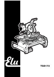
ENGLISH15 Dust extraction adapter16 Lock down pinA217 Operating handle18 Carrying handle19 Rail adjustment screws20 Rail lock knob21 Thumbscrew22 Grooving stop23 Fence adjustment knob24 Handhold25 Kerf plate26 Spindle lock buttonAssembly• Hold the guard up, press the spindle lock button (26) (fig. D2) andloosen the blade screw (31) by turning clockwise using the saw bladewrench (fig. D1).To use the spindle lock, press the button as shown and rotatethe spindle by hand until you feel the lock engage. Continue tohold the lock button in to keep the spindle from turning (fig. D2).• Remove the blade screw (31) and the outer flange (32) (fig. D1).• Install the saw blade (33) onto the inner flange making sure that theteeth at the bottom edge of the blade are pointing toward the back ofthe saw (away from the operator).• Replace the outer flange (32).• Tighten the blade locking screw (31) by turning counter-clockwise whileholding the lower guard up and the spindle lock engaged with yourother hand.Prior to assembly always unplug the tool.The motor and guards are already assembled onto the base.Stabilizer (fig. C)Your saw includes one base stabilizer (10).• Insert the stabilizer into the holes (27).• Move the stabilizer in or out until it contacts the work surface.• Tighten the screws (28).Never use your saw without the stabilizer.Bench mounting (fig. A2)• Holes (8) are provided in all four feet to facilitate bench mounting.Two different sized holes are provided to accommodate different sizesof bolts. Use either hole; it is not necessary to use both. Always mountyour saw firmly to prevent movement. To enhance the portability,the tool can be mounted to a piece of 12.5 mm or thicker plywoodwhich can then be clamped to your work support or moved to otherjob sites and reclamped.• When mounting your saw to a piece of plywood, make sure that themounting screws do not protrude from the bottom of the wood.The plywood must sit flush on the work support. When clamping thesaw to any work surface, clamp only on the clamping bosses wherethe mounting screw holes are located. Clamping at any other point willinterfere with the proper operation of the saw.• To prevent binding and inaccuracy, be sure the mounting surface is notwarped or otherwise uneven. If the saw rocks on the surface, place athin piece of material under one saw foot until the saw is firm on themounting surface.Mounting the saw blade (fig. A1, A2, D1 & D2)The teeth of a new blade are very sharp and can bedangerous.Lock the mitre lever (4), the rail lock knob (20) and the bevellever (11) (fig. A1 & A2).• Depress the head lock up release lever (50) to release the lower guard(2), then raise the lower guard as far as possible.• Loosen the upper guard cover screw (29) and pivot the upper guard (30) up.Never replace the screw (29) with a different screw!AdjustmentNever press the spindle lock while the blade is rotating.Prior to adjustment always unplug the tool.Your mitre saw was accurately adjusted at the factory. If readjustment dueto shipping and handling or any other reason is required, follow the stepsbelow to adjust your saw. Once made, these adjustments should remainaccurate.Checking and adjusting the blade to the fence (fig. E)• Loosen the mitre lever (4) and squeeze the mitre latch (5) upwards torelease the scale/mitre arm assembly (34).• Swing the mitre arm until the latch locates it at the 0° mitre position.Do not tighten the lever (4).• Pull down the head until the blade just enters the saw kerf (35).• Place a square (36) against the lower part (37) of the fence (7) andblade (33).Do not touch the tips of the blade teeth with the square.If adjustment is required, proceed as follows:• Loosen the four screws (38) and move the scale/mitre arm assembly (34)left or right until the blade is at 90° to the fence as measured withthe square.• Retighten the four screws (38). Pay no attention to the reading of themitre pointer at this point.Adjusting the mitre pointer (fig. F)• Loosen the mitre lever and squeeze the mitre latch to release thescale/mitre arm assembly (34).• Move the saw arm to set the mitre pointer (39) to the zero position.• With the mitre clamp knob loose, allow the mitre latch to snap intoplace as you rotate the mitre arm past zero.• Observe the pointer (39) and mitre scale (6). If the pointer does notindicate exactly zero, loosen the screw (40) and gently move thepointer left or right.• Retighten the screw (40).Mitre lock/detent rod adjustment (fig. G)If the base of the saw can be moved while the mitre lever (4) is locked,the mitre lock/detent rod (41) should be adjusted.• Unlock the mitre lever (4).en - 4 19
ENGLISH• Fully tighten the mitre lock/detent rod (41) by turning it clockwise usinga screwdriver (42). Turn counterclockwise 1/4 of a turn.• Check that the table will not rotate when the lever (4) is locked at arandom (not preset) angle.Bevel stop adjustment (fig. H1 - H4)Adjusting the bevel stop and pointer to 0° (fig. H1 & H2)• Place the saw in the 0° bevel position (fig. H1).• Push the head fully back and tighten the rail lock knob (20) (fig. H2).• Place a set square (36) on the table and up against the blade (33) (fig. H1).Do not touch the tips of the blade teeth with the square.If adjustment is required, proceed as follows:• Loosen the bevel lever (11) (fig. H2).• Press the mitre arm to the right, against the 0° bevel stop.• Adjust the screw (43) until the blade is perpendicular to the base.• Tighten the lever (11) securely.• Make sure the bevel pointer (44) indicates exactly 0°.• If not, loosen the screw (45), set the pointer to 0° and tighten the screw.Adjusting the bevel stop to 45° left or right (fig. H2 - H4)First, adjust the 0° bevel angle.- Left 45° bevel angle• Loosen the bevel lever (11) and tilt the head to the left (fig. H3).• If the pointer (44) does not indicate exactly 45°, turn the screw (12)on the left side until the pointer reads 45° (fig. H2).- Right 45° bevel angle• Depress the bevel stop override button (11A) and tilt the head tothe right (fig. H4).• If the pointer does not indicate exactly 45°, turn the screw (43A) onthe lower right side until the pointer reads 45° (fig. H3).Adjusting the fence (fig. A1 & J)The fences (3) and (7) can be adjusted to provide clearance, allowing thesaw to bevel to a full 48°.• Loosen the fence adjustment knob (23) and slide the fence to therequired position (fig. J).• Make a dry run with the saw turned OFF and check for clearance.Adjust the fence to be as close to the blade as practical to providemaximum workpiece support, without interfering with the up and downmovement of the arm.• Firmly tighten the fence adjustment knob (23).• Move the fences back after the cut has been accomplished.When bevelling to the right, it may be necessary to remove theright fence (3) (fig. A1)Rail guide adjustment (fig. K)• Regularly check the rails for clearance.• To reduce clearance, gradually rotate the set screws (19) clockwisewhile sliding the saw head back and forth.Instructions for useAlways observe the safety instructions and applicable regulations.The attention of UK users is drawn to the “woodworkingmachines regulations 1974” and any subsequent amendments.Prior to operation:• Make sure the guards have been mounted correctly. The saw bladeguard must be in closed position.• Make sure the saw blade rotates in the direction of the arrow on the blade.Switching ON and OFF (fig. L)• To run the tool, press the ON/OFF-switch (1).• To stop the tool, release the switch.• There is no provision for locking the switch ON, but a hole (47) isprovided for insertion of a padlock to lock the saw OFF.Basic saw cuts (fig. A1, A2, M1 - M3)Vertical straight cross cut (fig. A1 & A2)• Loosen the mitre lever (4) and squeeze the mitre latch (5) upwards.• Engage the mitre latch at the 0° position and tighten the lever (4).• Place the wood to be cut against the fences (3) and (7).• Take hold of the operating handle and depress the head lock uprelease lever (50) to release the head.• With the rail lock knob tightened, switch the saw ON.• Lower the head to allow the blade to cut through the workpiece andenter the kerf plate (25).• After completing the cut, release the switch, let the blade come to a fullstop and return the head to its upper rest position.Workpieces larger than 50 x 100 mm (fig. M1)The guide rail allows cutting larger workpieces using an out-down-back motion.• Release the rail lock knob (20).• Pull the saw towards you, lower the saw into the workpiece and push itback to complete the cut.• Proceed as described above.Vertical mitre cross-cut (fig. M2)• Loosen the fence clamping knobs and adjust the fences.• Loosen the mitre lever (4) and squeeze the mitre latch (5) upwards.Move the head left or right to the required angle.• Always ensure that the lever (4) is locked tightly before cutting.• Proceed as for a vertical straight cross-cut.Bevel cuts (fig. M3, H2 & H4)• Loosen the fence clamping knobs (23) and adjust the fences (3) and (7).Loosen the bevel lever (11) and set the required angle.• Tighten the lever (11) firmly.• To bevel to the right, depress the bevel stop override button (11A).Bevelling 48° to the left (fig. H2 & H3)To set a bevel angle greater than 45°, the bevel stop must be adjusted.• Loosen the bevel lever (11) and tilt the head to the left.• Turn the screw (12) until the pointer (44) indicates the desired bevelangle (up to 48°).Bevelling 48° to the right (fig. H2 - H4)To set a bevel angle greater than 45°, the bevel stop must be adjusted.• Depress the bevel stop override button (11A) and tilt the head to theright.• Turn the screw (43A) until the pointer (44) indicates the desired bevelangle (up to 48°).Quality of cutThe smoothness of any cut depends on a number of variables, e.g. thematerial being cut. When smoothest cuts are desired for moulding andother precision work, a sharp (60 tooth carbide) blade and a slower,even cutting rate will produce the desired results.20 en - 5