Manuale istruzione - Service après vente
Manuale istruzione - Service après vente
Manuale istruzione - Service après vente
Create successful ePaper yourself
Turn your PDF publications into a flip-book with our unique Google optimized e-Paper software.
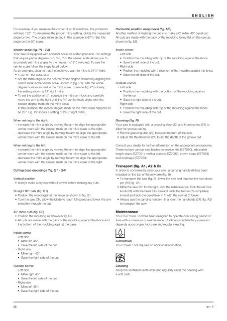
ENGLISHFor example, if you measure the corner of an 8 sided box, the protractorwill read 135°. To determine the proper mitre setting, divide the measuredangle by two. The proper mitre setting in this example is 67 1 /2. Set thisangle on the 90° scale.Vernier scale (fig. P1 - P3)Your saw is equipped with a vernier scale for added precision. For settingsthat require partial degrees ( 1 /4°, 1 /2°, 3 /4°), the vernier scale allows you toaccurately set mitre angles to the nearest 1 /2° (15 minutes). To use thevernier scale follow the steps listed below.As an example, assume that the angle you want to mitre is 24 1 /2° right.• Turn OFF the mitre saw.• Set the mitre angle to the nearest whole degree desired by aligning thecentre mark in the vernier scale, shown in (fig. P1), with the wholedegree number etched in the mitre scale. Examine (fig. P1) closely;the setting shown is 24° right mitre.• To set the additional 1 /2°, squeeze the mitre arm lock and carefullymove the arm to the right until the 1 /2° vernier mark aligns with theclosest degree mark on the mitre scale.In this example, the closest degree mark on the mitre scale happens tobe 25°. Fig. P2 shows a setting of 24 1 /2° right mitre.When mitring to the right:- increase the mitre angle by moving the arm to align the appropriatevernier mark with the closest mark on the mitre scale to the right.- decrease the mitre angle by moving the arm to align the appropriatevernier mark with the closest mark on the mitre scale to the left.When mitring to the left:- increase the mitre angle by moving the arm to align the appropriatevernier mark with the closest mark on the mitre scale to the left.- decrease the mitre angle by moving the arm to align the appropriatevernier mark with the closest mark on the mitre scale to the right.Cutting base mouldings (fig. Q1 - Q4)Vertical position• Always make a dry run without power before making any cuts.Straight 90° cuts (fig. Q1)• Position the wood against the fence as shown in fig. Q1.• Turn the saw ON, allow the blade to reach full speed and lower the armsmoothly through the cut.45° mitre cuts (fig. Q2)• Position the moulding as shown in fig. Q2.• All cuts are made with the back of the moulding against the fence andthe bottom of the moulding against the base.Inside corner- Left side• Mitre left 45°.• Save the left side of the cut.- Right side• Mitre right 45°.• Save the right side of the cut.Outside corner- Left side• Mitre right 45°.• Save the left side of the cut.- Right side• Mitre left 45°.• Save the right side of the cut.Horizontal position using bevel (fig. M3)Another method of making the cut is to make a 0° mitre, 45° bevel cut.All cuts are made with the back of the moulding laying flat on the saw asshown in fig. M3.Inside corner- Left side• Position the moulding with top of the moulding against the fence.• Save the left side of the cut.- Right side• Position the moulding with the bottom of the moulding against the fence.• Save the left side of the cut.Outside corner- Left side• Position the moulding with the bottom of the moulding againstthe fence.• Save the right side of the cut.- Right side• Position the moulding with top of the moulding against the fence.• Save the right side of the cut.Grooving (fig. R)Your saw is equipped with a grooving stop (22) and thumbscrew (21) toallow for groove cutting.• Flip the grooving stop (22) towards the front of the saw.• Adjust the thumbscrew (21) to set the depth of the groove cut.Consult your dealer for further information on the appropriate accessories.These include various saw blades, extension kits (EZ7080), adjustablelength stops (EZ7051), vertical clamps (EZ7082), crown stops (EZ7084)and dustbags (EZ7053).Transport (fig. A1, A2 & B)In order to conveniently carry your saw, a carrying handle (9) has beenincluded on the top of the saw arm (fig. B).• To transport the saw (fig. B), lower the arm and depress the lock downpin (16) (fig. A1).• Mitre the saw 60° to the right, lock the mitre lever (4), lock the rail lockknob (20) with the head fully forward, slide the fences (7) completelyinward and lock the bevel lever (11) with the saw at 0° bevel.• Always use the carrying handle (18) and/or the handholds (24) (fig. A2)to transport the saw.MaintenanceYour Elu Power Tool has been designed to operate over a long period oftime with a minimum of maintenance. Continuous satisfactory operationdepends upon proper tool care and regular cleaning.LubricationYour Power Tool requires no additional lubrication.CleaningKeep the ventilation slots clear and regularly clean the housing witha soft cloth.22 en - 7


