Prozessmessumformer RMA 422 - Endress+Hauser
Prozessmessumformer RMA 422 - Endress+Hauser
Prozessmessumformer RMA 422 - Endress+Hauser

Erfolgreiche ePaper selbst erstellen
Machen Sie aus Ihren PDF Publikationen ein blätterbares Flipbook mit unserer einzigartigen Google optimierten e-Paper Software.
Safety Manual<br />
SD 009R/09/de<br />
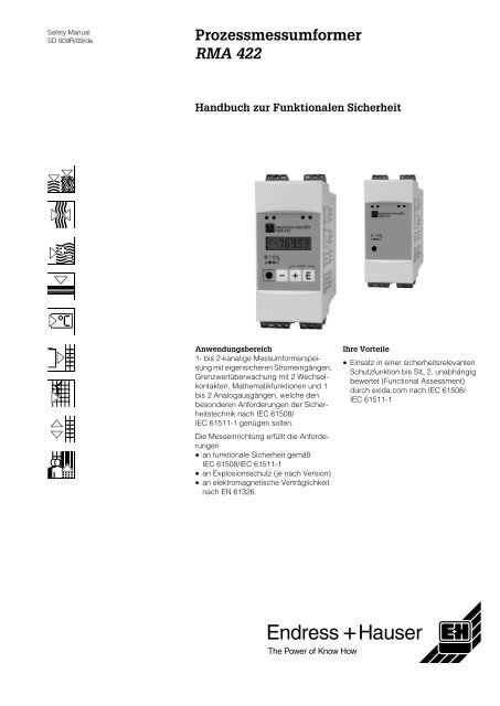
<strong>Prozessmessumformer</strong><br />
<strong>RMA</strong> <strong>422</strong><br />
Handbuch zur Funktionalen Sicherheit<br />
Anwendungsbereich<br />
1- bis 2-kanalige Messumformerspeisung<br />
mit eigensicheren Stromeingängen,<br />
Grenzwertüberwachung mit 2 Wechselkontakten,<br />
Mathematikfunktionen und 1<br />
bis 2 Analogausgängen, welche den<br />
besonderen Anforderungen der Sicherheitstechnik<br />
nach IEC 61508/<br />
IEC 61511-1 genügen sollen.<br />
Die Messeinrichtung erfüllt die Anforderungen<br />
• an funktionale Sicherheit gemäß<br />
IEC 61508/IEC 61511-1<br />
• an Explosionsschutz (je nach Version)<br />
• an elektromagnetische Verträglichkeit<br />
nach EN 61326.<br />
Ihre Vorteile<br />
• Einsatz in einer sicherheitsrelevanten<br />
Schutzfunktion bis SIL 2, unabhängig<br />
bewertet (Functional Assessment)<br />
durch exida.com nach IEC 61508/<br />
IEC 61511-1
Inhaltsverzeichnis<br />
SIL Konformitätserklärung . . . . . . . . . . . . . . . . . . . . 3<br />
Allgemeines . . . . . . . . . . . . . . . . . . . . . . . . . . . . . . . . 4<br />
Abkürzungen, Normen und Begriffe . . . . . . . . . . . . . . . . . . 4<br />
Bestimmung des Safety Integrity Level (SIL) . . . . . . . . . . . 4<br />
Sicherheitsfunktion mit <strong>RMA</strong> <strong>422</strong> . . . . . . . . . . . . . . 5<br />
Sicherheitsfunktion zur Grenztemperaturüberwachung . . . 5<br />
Angaben für die Sicherheitsfunktion . . . . . . . . . . . . . . . . . . 6<br />
Geräteversion . . . . . . . . . . . . . . . . . . . . . . . . . . . . . . . . . . . 6<br />
Mitgeltende Gerätedokumentationen <strong>RMA</strong> <strong>422</strong> . . . . . . . . . 6<br />
Inbetriebnahme und wiederkehrende Prüfungen. . 6<br />
Verwendung des <strong>RMA</strong> <strong>422</strong> für kontinuierliche<br />
Messungen . . . . . . . . . . . . . . . . . . . . . . . . . . . . . . . . . . . . . 6<br />
Einstellungen. . . . . . . . . . . . . . . . . . . . . . . . . . . . . . . 7<br />
Geräteeinstellungen . . . . . . . . . . . . . . . . . . . . . . . . . . . . . . 7<br />
Verriegelung . . . . . . . . . . . . . . . . . . . . . . . . . . . . . . . . . . . . 7<br />
Sicherheitstechnische Kenngrößen . . . . . . . . . . . . 7<br />
Spezifische sicherheitstechnische Kenngrößen für <strong>RMA</strong> <strong>422</strong><br />
. . . . . . . . . . . . . . . . . . . . . . . . . . . . . . . . . . . . . . . . . . . . . . . 7<br />
PFDAVG in Abhängigkeit vom gewählten<br />
Wartungsintervall . . . . . . . . . . . . . . . . . . . . . . . . . . . . . . . . . 8<br />
Exida.com management summary . . . . . . . . . . . . 10<br />
<strong>RMA</strong> <strong>422</strong><br />
2 <strong>Endress+Hauser</strong>
<strong>RMA</strong> <strong>422</strong><br />
SIL Konformitätserklärung<br />
Funktionale Sicherheit eines <strong>Prozessmessumformer</strong>s<br />
nach IEC 61508/IEC61511<br />
<strong>Endress+Hauser</strong> Wetzer GmbH+Co. KG, Obere Wank 1, 87484 Nesselwang<br />
erklärt als Hersteller, dass der <strong>Prozessmessumformer</strong><br />
<strong>RMA</strong> <strong>422</strong><br />
für den Einsatz in einer sicherheitsrelevanten Schutzfunktion entsprechend der IEC 61511-1<br />
geeignet ist, wenn zugehörige Sicherheitshinweise beachtet werden.<br />
Die FMEDA ergibt folgende Parameter:<br />
Produkt <strong>RMA</strong> <strong>422</strong> mit Analogausgang <strong>RMA</strong> <strong>422</strong> mit Relais<br />
Analogeingänge 1 2 1 2<br />
SIL 2<br />
Prüfintervall 1 Jahr<br />
Gerätetyp B<br />
HFT 1) 0 (einkanalige Verwendung)<br />
SFF > 86 % > 85 %<br />
2)<br />
PFDAVG<br />
-4<br />
3,90x10<br />
-4<br />
4,50x10<br />
-4<br />
3,86x10<br />
-4<br />
4,46x10<br />
MTBF 3) 160 Jahre 139 Jahre 154 Jahre 134 Jahre<br />
Sicherheitsfunktion 4)<br />
Überwachung min max Bereich min max Bereich<br />
λsd in FIT 245 55 291 283 69 343 9 9<br />
λsu in FIT 286 286 286 328 328 328 493 587<br />
λdd in FIT 60 250 14 74 289 14 14 14<br />
λdu in FIT 89 89 89 103 103 103 88 102<br />
1)<br />
gemäss Kapitel 11.4.4 der IEC 61511-1<br />
2)<br />
der Wert ist nach ISA S84.01 und IEC 61511-1 innerhalb des für SIL2 definierten Bereichs<br />
3)<br />
gemäss Siemens SN29500<br />
4)<br />
unter Annahme der Messumformereinstellung 4 bis 20 mA<br />
Im Rahmen des Nachweises der Betriebsbewährtheit wurde das Gerät einschließlich<br />
des Änderungswesens beurteilt.<br />
Nesselwang, 30. Januar 2004<br />
<strong>Endress+Hauser</strong> Wetzer GmbH+Co. KG<br />
Geschäftsführer<br />
+<br />
Endress<br />
The Power of Know How<br />
Hauser<br />
SIL-04001a/09/d<br />
<strong>Endress+Hauser</strong> 3
Abkürzungen, Normen und<br />
Begriffe<br />
Bestimmung des Safety<br />
Integrity Level (SIL)<br />
Allgemeines<br />
<strong>RMA</strong> <strong>422</strong><br />
Abkürzungen<br />
Erläuterungen der verwendeten Abkürzungen finden Sie in unserer SIL-Broschüre (SI002Z/11).<br />
Relevante Normen<br />
Norm Englisch Deutsch<br />
IEC 61508,<br />
Teil 1 – 7<br />
IEC 61511,<br />
Teil 1– 3 (FDIS)<br />
Begriffe<br />
Begriff Erklärung<br />
gefahrbringender<br />
Ausfall<br />
sicherheitsbezogenes<br />
System<br />
Functional safety of electrical/electronic/<br />
programmable electronic safety-related<br />
systems<br />
(Target group: Manufacturers and Suppliers<br />
of Devices)<br />
Functional safety – Safety Instrumented<br />
Systems for the process industry sector<br />
(Target group: Safety Instrumented Systems<br />
Designers, Integrators and Users)<br />
Funktionale Sicherheit sicherheitsbezogenerelektrischer/elektronischer/programmierbarer<br />
elektronischer Systeme<br />
(Zielgruppe: Hersteller und Lieferanten<br />
von Geräten)<br />
Funktionale Sicherheit – Sicherheitstechnische<br />
Systeme für die Prozessindustrie<br />
(Zielgruppe: Planer, Errichter und Nutzer)<br />
Ausfall mit dem Potenzial, das sicherheitsbezogene System in einen gefährlichen<br />
oder funktionsunfähigen Zustand zu versetzen.<br />
Ein sicherheitsbezogenes System führt die Sicherheitsfunktionen aus, die erforderlich<br />
sind, um einen sicheren Zustand z.B. in einer Anlage zu erreichen oder<br />
aufrechtzuerhalten. Beispiel: Temperaturmessgerät – Logikeinheit (z.B. Grenzsignalgeber)<br />
– Ventil bilden ein sicherheitsbezogenes System.<br />
Sicherheitsfunktion Definierte Funktion, die von einem sicherheitsbezogenen System ausgeführt<br />
wird, mit dem Ziel, unter Berücksichtigung eines festgelegten gefährlichen Vorfalls,<br />
einen sicheren Zustand für die Anlage zu erreichen oder aufrechtzuerhalten.<br />
Beispiel: Grenztemperaturüberwachung<br />
Der erreichbare Safety Integrity Level wird durch folgende sicherheitstechnischen Kenngrößen<br />
bestimmt:<br />
• mittlere Wahrscheinlichkeit gefahrbringender Ausfälle einer Sicherheitsfunktion im Anforderungsfall<br />
(PFDAVG) • Hardware Fehlertoleranz (HFT) und<br />
• Anteil ungefährlicher Ausfälle (SFF).<br />
Die spezifischen sicherheitstechnischen Kenngrößen für den <strong>RMA</strong> <strong>422</strong>, als Teil der Sicherheitsfunktion,<br />
sind im Kapitel "Sicherheitstechnische Kenngrößen" aufgeführt.<br />
Die folgende Tabelle zeigt die Abhängigkeit des "Safety Integrity Level" (SIL) von der "mittleren<br />
Wahrscheinlichkeit gefahrbringender Ausfälle einer Sicherheitsfunktion des gesamten sicherheitsbezogenen<br />
Systems" (PFDAVG ). Dabei wird der "Low demand mode" betrachtet, d.h. die<br />
Anforderungsrate an das sicherheitsbezogene System ist maximal einmal im Jahr.<br />
Safety Integrity Level (SIL) PFD AVG (Low demand mode)<br />
4 ≥ 10 –5 ...< 10 –4<br />
3 ≥ 10 –4 ...< 10 –3<br />
2 ≥ 10 –3 ...< 10 –2<br />
1 ≥ 10 –2 ...< 10 –1<br />
Sensor, <strong>Prozessmessumformer</strong>, Logikeinheit und Aktor bilden zusammen ein sicherheitsbezogenes<br />
System, das eine Sicherheitsfunktion ausführt. Die "mittlere Wahrscheinlichkeit gefahrbringender<br />
Ausfälle des gesamten sicherheitsbezogenen Systems" (PFD AVG ) teilt sich auf die Teilsysteme<br />
Sensor, <strong>Prozessmessumformer</strong>, Logikeinheit und Aktor üblicherweise gemäß Abbildung 1<br />
auf.<br />
4 <strong>Endress+Hauser</strong>
<strong>RMA</strong> <strong>422</strong><br />
Sicherheitsfunktion zur<br />
Grenztemperaturüberwachung<br />
Sensor<br />
(z.B. Temperaturmessgerät)<br />
Abb. 1: Anteil des <strong>Prozessmessumformer</strong>s an der "mittleren Wahrscheinlichkeit gefahrbringender Ausfälle<br />
einer Sicherheitsfunktion im Anforderungsfall" (PFD AVG )<br />
Hinweis!<br />
Diese Dokumentation behandelt den <strong>RMA</strong> <strong>422</strong> als Teil einer Sicherheitsfunktion.<br />
Safety Integrity Level <strong>RMA</strong> <strong>422</strong> (Typ B)<br />
Die folgende Tabelle zeigt den erreichbaren "Safety Integrity Level" (SIL) des gesamten sicherheitsbezogenen<br />
Systems für Systeme vom Typ B abhängig vom "Anteil ungefährlicher Ausfälle"<br />
(SFF) und der "Hardware Fehlertoleranz" (HFT). Systeme vom Typ B sind z.B. Sensoren mit komplexen<br />
Komponenten wie z.B. ASICs (→ siehe auch IEC 61508, Teil 2).<br />
Anteil ungefährlicher<br />
Ausfälle (SFF)<br />
Sicherheitsfunktion mit <strong>RMA</strong> <strong>422</strong><br />
Abb. 2: Sicherheitsfunktion mit <strong>RMA</strong> <strong>422</strong><br />
<strong>Prozessmessumformer</strong><br />
(z.B. <strong>RMA</strong> <strong>422</strong>)<br />
PFDAVG ≤ 10%<br />
Hardware Fehlertoleranz (HFT)<br />
0 1 (0) 1<br />
Logikeinheit<br />
(z.B. SPS)<br />
Aktor<br />
(z.B. Ventil)<br />
1) Nach IEC 61511-1, Abschnitt 11.4.3 kann bei Sensoren und Aktoren mit komplexen Komponenten die<br />
"Hardware Fehlertoleranz" (HFT) um eins reduziert werden (Werte in Klammern), wenn für das Gerät<br />
folgende Bedingungen zutreffen:<br />
- Das Gerät ist betriebsbewährt.<br />
- Der Anwender kann nur prozessbezogene Parameter konfigurieren, z.B. Messbereich, Signalrichtung<br />
im Fehlerfall usw.<br />
- Die Konfigurationsebene des Gerätes ist geschützt, z.B. über eine Brücke oder ein Passwort (hier:<br />
Zahlencode)<br />
- Die Funktion hat einen geforderten "Safety integrety Level" (SIL) von weniger als 4.<br />
Alle Bedingungen treffen für den <strong>RMA</strong> <strong>422</strong> zu.<br />
<strong>Endress+Hauser</strong> 5<br />
2 (1) 1<br />
< 60 % nicht erlaubt SIL 1 SIL 2<br />
60...< 90 % SIL 1 SIL 2 SIL 3<br />
90...< 99 % SIL 2 SIL 3 –<br />
≥ 99 % SIL 3 – –<br />
ENDRESS+HAUSER<br />
<strong>RMA</strong> <strong>422</strong><br />
Sensor z.B.<br />
Temperaturmessgerät<br />
<strong>Prozessmessumformer</strong><br />
<strong>RMA</strong> <strong>422</strong><br />
4…20 mA<br />
Logikeinheit<br />
e.g. SPS,<br />
Grenzsignalgeber<br />
usw.<br />
Aktor
<strong>RMA</strong> <strong>422</strong><br />
Die Sensoren, gespeist mit dem <strong>Prozessmessumformer</strong> <strong>RMA</strong> <strong>422</strong>, erzeugen ein dem Messwert<br />
proportionales analoges Signal (4 bis 20 mA). Mathematikfunktionen ermöglichen die Bildung<br />
einer neuen Prozessgröße. Der <strong>Prozessmessumformer</strong> gibt die zur neuen Prozessgröße proportionalen<br />
analogen Signale an eine nachgeschaltete Logikeinheit wie z.B. eine SPS weiter. Die<br />
Grenzwertüberwachung kann auch direkt mit dem <strong>RMA</strong> <strong>422</strong> über 2 Wechselkontakte erfolgen.<br />
Angaben für die Sicherheitsfunktion<br />
" Achtung!<br />
Angaben für die Sicherheitsfunktionen sind im Kapitel "Sicherheitstechnische Kenngrößen" aufgeführt.<br />
! Hinweis!<br />
MTTR wird mit 8 Stunden angesetzt.<br />
Sicherheitsbezogene Systeme ohne selbstverriegelnde Funktion müssen nach Ausführung der<br />
Sicherheitsfunktion innerhalb MTTR in einen überwachten oder anderweitig sicheren Zustand<br />
gebracht werden.<br />
Geräteversion SIL ab Serien-Nr. 5C00104114, Dezember 2002<br />
Mitgeltende Gerätedokumentationen<br />
<strong>RMA</strong> <strong>422</strong><br />
Verwendung des <strong>RMA</strong> <strong>422</strong><br />
für kontinuierliche<br />
Messungen<br />
Für den <strong>Prozessmessumformer</strong> <strong>RMA</strong> <strong>422</strong> müssen je nach Ausführung folgende Dokumentationen<br />
vorhanden sein:<br />
Zündschutzart/Zertifikat Betriebsanleitung weitere Ex-Dokumentation<br />
keine BA 103R keine<br />
ATEX II(1)GD [EEx ia] IIC BA 103R Sicherheitshinweise XA 003R<br />
" Achtung!<br />
• Die Installations- und Einstellhinweise sowie die technischen Grenzwerte sind gemäß der<br />
Betriebsanleitung (BA 103R) zu beachten.<br />
• Für Geräte, die im explosionsgefährdeten Bereich eingesetzt werden, sind zusätzlich die entsprechenden<br />
Sicherheitshinweise (XA) bzw. Control Drawings gemäß den obigen Tabellen zu<br />
beachten.<br />
Zusätzliche Dokumentation <strong>RMA</strong> <strong>422</strong><br />
Für weitere Informationen siehe Technische Information TI 072R.<br />
Inbetriebnahme und wiederkehrende Prüfungen<br />
Die Funktionsfähigkeit der Sicherheitseinrichtung ist in angemessenen Zeitabständen zu prüfen.<br />
Es liegt in der Verantwortung des Betreibers, die Art der Überprüfung und die Zeitabstände im<br />
genannten Zeitraum zu wählen. Die Prüfung ist so durchzuführen, dass die einwandfreie Funktion<br />
der Sicherheitseinrichtung im Zusammenwirken aller Komponenten nachgewiesen wird.<br />
6 <strong>Endress+Hauser</strong>
<strong>RMA</strong> <strong>422</strong><br />
Einstellungen<br />
Geräteeinstellungen Beim <strong>RMA</strong> <strong>422</strong> können Sie verschiedene Softwareeinstellungen vornehmen.<br />
Beim Einsatz als Teil einer Sicherheitsfunktion darf entweder ein Analogausgang oder ein Grenzwertrelais<br />
verwendet werden. Welche Einstellungen beim Einsatz des <strong>RMA</strong> <strong>422</strong> in einer sicherheitsrelevanten<br />
Applikation zulässig bzw. unzulässig sind zeigt die nachfolgende Tabelle:<br />
<strong>RMA</strong> <strong>422</strong> mit Stromausgang:<br />
<strong>RMA</strong> <strong>422</strong> mit Relais:<br />
Weitere Informationen entnehmen Sie der Betriebsanleitung BA 103R.<br />
" Achtung!<br />
Überprüfen Sie nach Eingabe aller Parameter die Sicherheitsfunktion.<br />
Verriegelung Zum Schutz der prozessrelevanten Parameter vor Änderung, muss die Gerätebedienung<br />
gesperrt werden. Dies geschieht mit Hilfe eines durch den Anwender wählbaren Codes.<br />
Spezifische sicherheitstechnische<br />
Kenngrößen für<br />
<strong>RMA</strong> <strong>422</strong><br />
Mit Analogeing. 4-20 mA<br />
und Analogausg. 4-20 mA<br />
Parameter Einstellmöglichkeiten Einstellung für Sicherheitsfunktion<br />
Ausgangsbereich 4-20 mA zulässig<br />
0-20 mA nicht zulässig<br />
0-10 V nicht zulässig<br />
Verhalten im Fehlerfall hold nicht zulässig<br />
min zulässig<br />
max zulässig<br />
Parameter Einstellmöglichkeiten Einstellung für Sicherheitsfunktion<br />
Betriebsart off nicht zulässig<br />
min zulässig<br />
max zulässig<br />
trd zulässig<br />
alarm zulässig<br />
min- nicht zulässig<br />
max- nicht zulässig<br />
trd- nicht zulässig<br />
Parameter Einstellmöglichkeit Einstellung für Sicherheitsfunktion<br />
Benutzer Code 0000 bis 9999 0001 bis 9999 (0000 ist nicht zulässig,<br />
da kein Benutzercode aktiv)<br />
Sicherheitstechnische Kenngrößen<br />
Die Tabelle zeigt die spezifischen sicherheitstechnischen Kenngrößen für den <strong>RMA</strong> <strong>422</strong>:<br />
Mit 2 Analogeing. 4-20 mA<br />
und Analogausg. 4-20 mA<br />
Mit Analogeingang 4-20 mA<br />
und Relais<br />
SIL SIL 2 SIL 2 SIL 2 SIL 2<br />
HFT 0 0 0 0<br />
Mit 2 Analogeing. 4-20 mA<br />
und Relais<br />
<strong>Endress+Hauser</strong> 7
Mit Analogeing. 4-20 mA<br />
und Analogausg. 4-20 mA<br />
SFF > 86% > 86% > 85% > 85%<br />
PFD AVG 3,90 x 10 –4 4,50 x 10 –4 3,86 x 10 –4 4,46 x 10 –4<br />
TI 1 jährlich jährlich jährlich jährlich<br />
1) vollständiger Funktionstest<br />
PFD AVG in Abhängigkeit<br />
vom gewählten<br />
Wartungsintervall<br />
Mit 2 Analogeing. 4-20 mA<br />
und Analogausg. 4-20 mA<br />
Mit Analogeingang 4-20 mA<br />
und Relais<br />
<strong>RMA</strong> <strong>422</strong><br />
Mit 2 Analogeing. 4-20 mA<br />
und Relais<br />
Das folgende Diagramm stellt die Abhängigkeit PFD AVG vom Wartungsintervall dar. PFD AVG steigt<br />
mit steigendem Wartungsintervall.<br />
Probability<br />
1oo1D structure<br />
4,50E-03<br />
4,00E-03<br />
3,50E-03<br />
3,00E-03<br />
2,50E-03<br />
2,00E-03<br />
1,50E-03<br />
1,00E-03<br />
5,00E-04<br />
0,00E+00<br />
0 1 2 3 4 5 6 7 8 9 10<br />
PFDavg<br />
Years<br />
Abb. 3: "Mittlere Wahrscheinlichkeit gefahrbringender Ausfälle des sicherheitsbezogenem Systems auf Anforderung"<br />
(PVD AVG) in Abhängigkeit vom gewählten Wartungsintervall beim <strong>RMA</strong> <strong>422</strong> mit Analogeingang<br />
4-20 mA und Analogausgang 4-20 mA.<br />
Probability<br />
5,00E-03<br />
4,50E-03<br />
4,00E-03<br />
3,50E-03<br />
3,00E-03<br />
2,50E-03<br />
2,00E-03<br />
1,50E-03<br />
1,00E-03<br />
5,00E-04<br />
0,00E+00<br />
1oo1D structure<br />
0 1 2 3 4 5 6 7 8 9 10<br />
PFDavg<br />
Years<br />
Abb. 4: "Mittlere Wahrscheinlichkeit gefahrbringender Ausfälle des sicherheitsbezogenem Systems auf Anforderung"<br />
(PVD AVG ) in Abhängigkeit vom gewählten Wartungsintervall beim <strong>RMA</strong> <strong>422</strong> mit 2 Analogeingängen<br />
4-20 mA und Analogausgang 4-20 mA.<br />
8 <strong>Endress+Hauser</strong>
<strong>RMA</strong> <strong>422</strong><br />
Probability<br />
1oo1D structure<br />
4,50E-03<br />
4,00E-03<br />
3,50E-03<br />
3,00E-03<br />
2,50E-03<br />
2,00E-03<br />
1,50E-03<br />
1,00E-03<br />
5,00E-04<br />
0,00E+00<br />
0 1 2 3 4 5 6 7 8 9 10<br />
PFDavg<br />
Years<br />
Abb. 5: "Mittlere Wahrscheinlichkeit gefahrbringender Ausfälle des sicherheitsbezogenem Systems auf Anforderung"<br />
(PVD AVG ) in Abhängigkeit vom gewählten Wartungsintervall beim <strong>RMA</strong> <strong>422</strong> mit Analogeingang<br />
4-20 mA und Relais.<br />
Probability<br />
5,00E-03<br />
4,50E-03<br />
4,00E-03<br />
3,50E-03<br />
3,00E-03<br />
2,50E-03<br />
2,00E-03<br />
1,50E-03<br />
1,00E-03<br />
5,00E-04<br />
0,00E+00<br />
1oo1D structure<br />
0 1 2 3 4 5 6 7 8 9 10<br />
PFDavg<br />
Years<br />
Abb. 6: "Mittlere Wahrscheinlichkeit gefahrbringender Ausfälle des sicherheitsbezogenem Systems auf Anforderung"<br />
(PVD AVG ) in Abhängigkeit vom gewählten Wartungsintervall beim <strong>RMA</strong> <strong>422</strong> mit 2 Analogeingängen<br />
4-20 mA und Relais.<br />
<strong>Endress+Hauser</strong> 9
Management summary<br />
This report summarizes the results of the hardware assessment with prior-use consideration<br />
according to IEC 61508 / IEC 61511 carried out on the Process Transmitter <strong>RMA</strong> <strong>422</strong> with<br />
software version V 1.12.<br />
Exida.com management summary<br />
The hardware assessment consists of a Failure Modes, Effects and Diagnostics Analysis<br />
(FMEDA). A FMEDA is one of the steps taken to achieve functional safety assessment of a<br />
device per IEC 61508. From the FMEDA, failure rates are determined and consequently the<br />
Safe Failure Fraction (SFF) is calculated for the device. For full assessment purposes all<br />
requirements of IEC 61508 must be considered.<br />
The failure rates used in this analysis are the basic failure rates from the Siemens standard<br />
SN 29500.<br />
FMEDA and Prior-use Assessment<br />
According to table 2 of IEC 61508-1 the average PFD for systems operating in low demand<br />
mode has to be ≥10 -3 to < 10 -2 for SIL 2 safety functions. However, as the module under<br />
consideration is only one part of an entire safety function it should not claim more than 10% of<br />
this range. For a SIL 2 application the total PFDAVG value of the SIF should be smaller than<br />
1,00E-02, hence the maximum allowable PFDAVG value for the process transmitter would then<br />
be 1,00E-03.<br />
Project:<br />
Process Transmitter <strong>RMA</strong> <strong>422</strong><br />
The Process Transmitter <strong>RMA</strong> <strong>422</strong> is considered to be a Type B 1 component with a hardware<br />
fault tolerance of 0.<br />
Type B components with a SFF of 60% to < 90% must have a hardware fault tolerance of 1<br />
according to table 3 of IEC 61508-2 for SIL 2 (sub-) systems.<br />
For safety applications only the current or relay output shall be used. All other possible output<br />
variants or electronics are not covered by this report.<br />
Customer:<br />
<strong>Endress+Hauser</strong> Wetzer GmbH + Co. KG<br />
Nesselwang<br />
Germany<br />
As the Process Transmitter <strong>RMA</strong> <strong>422</strong> is supposed to be a proven-in-use device, an assessment<br />
of the hardware with additional prior-use demonstration for the device was carried out. The<br />
prior-use investigation was based on field return data collected and analyzed by<br />
<strong>Endress+Hauser</strong> Wetzer GmbH + Co. KG.<br />
According to the requirements of IEC 61511-1 First Edition 2003-01 section 11.4.4 and the<br />
assessment described in section 5.2 the device is considered to be suitable for use in SIL 2<br />
safety functions. The decision on the usage of prior-use devices, however, is always with the<br />
end-user.<br />
Contract No.: E+H 03/02-17<br />
Report No.: E+H 03/02-17 R021<br />
Version V1, Revision R1.0, January 2004<br />
Stephan Aschenbrenner<br />
Assuming that a connected logic solver can detect both over-range (fail high) and under-range<br />
(fail low), high and low failures can be classified as safe detected failures or dangerous detected<br />
failures depending on whether the Process Transmitter <strong>RMA</strong> <strong>422</strong> is used in an application for<br />
“low level monitoring”, “high level monitoring” or “range monitoring”. For these applications the<br />
following tables show how the above stated requirements are fulfilled.<br />
<strong>RMA</strong> <strong>422</strong><br />
10 <strong>Endress+Hauser</strong><br />
Type B component: “Complex” component (using micro controllers or programmable logic); for details<br />
see 7.4.3.1.3 of IEC 61508-2.<br />
© exida.com GmbH e+h 03-02-17 r021 v1 r1.0, January 27, 2004<br />
Stephan Aschenbrenner Page 2 of 29<br />
The document was prepared using best effort. The authors make no warranty of any kind and shall not be liable in<br />
any event for incidental or consequential damages in connection with the application of the document.<br />
© All rights reserved.
<strong>RMA</strong> <strong>422</strong><br />
Table 5: Summary for <strong>RMA</strong> <strong>422</strong> with relay output and one input – PFDAVG values<br />
Table 1: Summary for <strong>RMA</strong> <strong>422</strong> with current output and one input – PFDAVG values<br />
T[Proof] = 1 year T[Proof] = 5 years T[Proof] = 10 years<br />
T[Proof] = 1 year T[Proof] = 5 years T[Proof] = 10 years<br />
PFDAVG = 3,86E-04 PFDAVG = 1,93E-03 PFDAVG = 3,85E-03<br />
PFDAVG = 3,90E-04 PFDAVG = 1,95E-03 PFDAVG = 3,89E-03<br />
Table 6: Summary for <strong>RMA</strong> <strong>422</strong> with relay output and one input – Failure rates<br />
Table 2: Summary for <strong>RMA</strong> <strong>422</strong> with current output and one input – Failure rates<br />
λsd λsu λdd λdu SFF DCS DCD<br />
9 FIT 493 FIT 14 FIT 88 FIT > 85% 2% 14%<br />
Failure Categories λsd λsu λdd λdu SFF DCS 2 DCD<br />
245 FIT 286 FIT 60 FIT 89 FIT > 86% 46% 40%<br />
λlow = λsd<br />
λhigh = λdd<br />
Table 7: Summary for <strong>RMA</strong> <strong>422</strong> with relay output and two inputs – PFDAVG values<br />
55 FIT 286 FIT 250 FIT 89 FIT > 86% 16% 74%<br />
λlow = λdd<br />
λhigh = λsd<br />
T[Proof] = 1 year T[Proof] = 5 years T[Proof] = 10 years<br />
PFDAVG = 4,46E-04 PFDAVG = 2,23E-03 PFDAVG = 4,45E-03<br />
291 FIT 286 FIT 14 FIT 89 FIT > 86% 50% 14%<br />
λlow = λsd<br />
λhigh = λsd<br />
Table 8: Summary for <strong>RMA</strong> <strong>422</strong> with relay output and two inputs – Failure rates<br />
λsd λsu λdd λdu SFF DCS DCD<br />
9 FIT 587 FIT 14 FIT 102 FIT > 85% 2% 12%<br />
Table 3: Summary for <strong>RMA</strong> <strong>422</strong> with current output and two inputs – PFDAVG values<br />
T[Proof] = 1 year T[Proof] = 5 years T[Proof] = 10 years<br />
The boxes marked in yellow ( ) mean that the calculated PFDAVG values are within the<br />
allowed range for SIL 2 according to table 2 of IEC 61508-1 but do not fulfill the requirement to<br />
not claim more than 10% of this range, i.e. to be better than or equal to 1,00E-03. The boxes<br />
marked in green ( ) mean that the calculated PFDAVG values are within the allowed range for<br />
SIL 2 according to table 2 of IEC 61508-1 and table 3.1 of ANSI/ISA–84.01–1996 and do fulfill<br />
the requirement to not claim more than 10% of this range, i.e. to be better than or equal to<br />
1,00E-03.<br />
PFDAVG = 4,50E-04 PFDAVG = 2,25E-03 PFDAVG = 4,49E-03<br />
The functional assessment has shown that the Process Transmitter <strong>RMA</strong> <strong>422</strong> has a<br />
PFDAVG within the allowed range for SIL 2 according to table 2 of IEC 61508-1 and<br />
table 3.1 of ANSI/ISA–84.01–1996 and a Safe Failure Fraction (SFF) of > 85%. Based on<br />
the verification of "prior use" it can be used as a single device for SIL2 Safety Functions<br />
in terms of IEC 61511-1 First Edition 2003-01.<br />
A user of the Process Transmitter <strong>RMA</strong> <strong>422</strong> can utilize these failure rates in a probabilistic<br />
model of a safety instrumented function (SIF) to determine suitability in part for safety<br />
instrumented system (SIS) usage in a particular safety integrity level (SIL). The complete list of<br />
failure rates is presented in section 5.1 to 5.4 along with all assumptions.<br />
The two inputs and the two outputs on each module shall not be used to increase the hardware<br />
fault tolerance, needed to achieve a higher SIL for a certain safety function, as they contain<br />
common components. The two inputs are only allowed to be used to combine two safety critical<br />
input signals using the basic mathematics modes of addition / subtraction / multiplication to<br />
calculate further process values.<br />
It is important to realize that the “don’t care” failures and the “annunciation” failures are<br />
classified as “safe undetected” failures according to IEC 61508. Note that these failures on its<br />
own will not affect system reliability or safety, and should not be included in spurious trip<br />
calculations.<br />
<strong>Endress+Hauser</strong> 11<br />
Table 4: Summary for <strong>RMA</strong> <strong>422</strong> with current output and two inputs – Failure rates<br />
Failure Categories λsd λsu λdd λdu SFF DCS DCD<br />
283 FIT 328 FIT 74 FIT 103 FIT > 86% 46% 42%<br />
λlow = λsd<br />
λhigh = λdd<br />
69 FIT 328 FIT 289 FIT 103 FIT > 86% 17% 74%<br />
λlow = λdd<br />
λhigh = λsd<br />
343 FIT 328 FIT 14 FIT 103 FIT > 86% 51% 12%<br />
λlow = λsd<br />
λhigh = λsd<br />
2 DC means the diagnostic coverage (safe or dangerous) of the safety logic solver for <strong>RMA</strong> <strong>422</strong>.<br />
© exida.com GmbH e+h 03-02-17 r021 v1 r1.0, January 27, 2004<br />
Stephan Aschenbrenner Page 4 of 29<br />
© exida.com GmbH e+h 03-02-17 r021 v1 r1.0, January 27, 2004<br />
Stephan Aschenbrenner Page 3 of 29
Zwei Telefonnummern - immer richtig verbunden!<br />
Bei Anwahl der gebührenfreien Telefonnummer<br />
0 800 3 48 37 87 (0 800 EHVERTRIEB) oder 0 800 3 47 37 84 (0 800 EHSERVICE)<br />
werden Sie über Ihre Vorwahl automatisch an das zuständige Technische Büro<br />
zu Ihrem Ansprechpartner vermittelt.<br />
Deutschland Österreich Schweiz<br />
Vertrieb: Service: <strong>Endress+Hauser</strong><br />
Beratung<br />
Information<br />
Auftrag<br />
Bestellung<br />
Help-Desk<br />
Feldservice<br />
Ersatzteile/Reparatur<br />
Kalibrierung<br />
Telefon: Telefon: Telefax:<br />
0 800 EHVERTRIEB<br />
0 800 3 48 37 87<br />
0 800 EHSERVICE<br />
0 800 3 47 37 84<br />
Messtechnik<br />
GmbH+Co. KG<br />
Colmarer Straße 6<br />
D-79576 Weil am Rhein<br />
0 800 EHFAXEN<br />
0 800 3 43 29 36<br />
<strong>Endress+Hauser</strong><br />
Messtechnik Ges.m.b.H.<br />
Lehnergasse 4<br />
A-1230 Wien<br />
Tel. (01) 8 80 56-0<br />
Fax (01) 8 80 56-335<br />
E-Mail:<br />
info@at.endress.com<br />
<strong>Endress+Hauser</strong><br />
Metso AG<br />
Sternenhofstraße 21<br />
<strong>RMA</strong> <strong>422</strong><br />
CH-4153 Reinach/BL1<br />
Tel. (0 61) 7 15 75 75<br />
Fax (0 61) 7 11 16 50<br />
E-Mail:<br />
info@ch.endress.com<br />
E-Mail: E-Mail: Internet: Internet:<br />
info@de.endress.com service@de.endress.com www.at.endress.com www.ch.endress.com<br />
Internet: www.de.endress.com<br />
Technische Büros in: Hamburg . Hannover . Ratingen . Frankfurt . Stuttgart . München . Teltow<br />
08.02<br />
SD 009R/09/de/02.04<br />
FM+SGML 6.0 ProMoDo