FS15R12YT3 - Infineon
FS15R12YT3 - Infineon
FS15R12YT3 - Infineon

Erfolgreiche ePaper selbst erstellen
Machen Sie aus Ihren PDF Publikationen ein blätterbares Flipbook mit unserer einzigartigen Google optimierten e-Paper Software.
TechnischeInformation/technicalinformation<br />
IGBT-Module<br />
IGBT-modules<br />
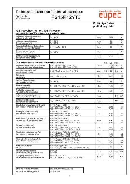
IGBT-Wechselrichter/IGBT-inverter<br />
HöchstzulässigeWerte/maximumratedvalues<br />
Kollektor-Emitter-Sperrspannung<br />
collector-emitter voltage<br />
Kollektor-Dauergleichstrom<br />
DC-collector current<br />
Periodischer Kollektor Spitzenstrom<br />
repetitive peak collector current<br />
Gesamt-Verlustleistung<br />
total power dissipation<br />
Gate-Emitter-Spitzenspannung<br />
gate-emitter peak voltage<br />
prepared by: Peter Kanschat<br />
approved by: Ralf Keggenhoff<br />
<strong>FS15R12YT3</strong><br />
date of publication: 2003-5-16<br />
revision: 2.0<br />
1<br />
VorläufigeDaten<br />
preliminarydata<br />
TÝÎ = 25°C V†Š» 1200 V<br />
T† = 80°C<br />
T† = 25°C<br />
I† ÒÓÑ<br />
I†<br />
t« = 1 ms, T† = 80°C I†ç¢ 30 A<br />
T† = 25°C PÚÓÚ 110 W<br />
15<br />
25<br />
A<br />
A<br />
V•Š» +/-20 V<br />
CharakteristischeWerte/characteristicvalues min. typ. max.<br />
Kollektor-Emitter Sättigungsspannung<br />
collector-emitter saturation voltage<br />
Gate-Schwellenspannung<br />
gate threshold voltage<br />
Gateladung<br />
gate charge<br />
Interner Gatewiderstand<br />
internal gate resistor<br />
Eingangskapazität<br />
input capacitance<br />
Rückwirkungskapazität<br />
reverse transfer capacitance<br />
Kollektor-Emitter Reststrom<br />
collector-emitter cut-off current<br />
Gate-Emitter Reststrom<br />
gate-emitter leakage current<br />
Einschaltverzögerungszeit (ind. Last)<br />
turn-on delay time (inductive load)<br />
Anstiegszeit (induktive Last)<br />
rise time (inductive load)<br />
Abschaltverzögerungszeit (ind. Last)<br />
turn-off delay time (inductive load)<br />
Fallzeit (induktive Last)<br />
fall time (inductive load)<br />
Einschaltverlustenergie pro Puls<br />
turn-on energy loss per pulse<br />
Abschaltverlustenergie pro Puls<br />
turn-off energy loss per pulse<br />
Kurzschlußverhalten<br />
SC data<br />
Innerer Wärmewiderstand<br />
thermal resistance, junction to case<br />
Übergangs-Wärmewiderstand<br />
thermal resistance, case to heatsink<br />
I† = 15 A, V•Š = 15 V, TÝÎ = 25°C<br />
I† = 15 A, V•Š = 15 V, TÝÎ = 125°C<br />
V†Š ÙÈÚ 1,70<br />
1,90<br />
2,15 V<br />
V<br />
I† = 0,60 mA, V†Š = V•Š, TÝÎ = 25°C V•ŠÚÌ 5,0 5,8 6,5 V<br />
V•Š = -15 V ... +15 V Q• 0,15 µC<br />
TÝÎ = 25°C R•ÍÒÚ 0,0 Â<br />
f = 1 MHz, TÝÎ = 25°C, V†Š = 25 V, V•Š = 0 V CÍþÙ 1,10 nF<br />
f = 1 MHz, TÝÎ = 25°C, V†Š = 25 V, V•Š = 0 V CØþÙ 0,04 nF<br />
V†Š = 1200 V, V•Š = 0 V, TÝÎ = 25°C I†Š» 5,0 mA<br />
V†Š = 0 V, V•Š = 20 V, TÝÎ = 25°C I•Š» 400 nA<br />
I† = 15 A, V†Š = 600 V<br />
V•Š = ±15 V, R•ÓÒ = 62 Â, TÝÎ = 25°C<br />
V•Š = ±15 V, R•ÓÒ = 62 Â, TÝÎ = 125°C<br />
I† = 15 A, V†Š = 600 V<br />
V•Š = ±15 V, R•ÓÒ = 62 Â, TÝÎ = 25°C<br />
V•Š = ±15 V, R•ÓÒ = 62 Â, TÝÎ = 125°C<br />
I† = 15 A, V†Š = 600 V<br />
V•Š = ±15 V, R•ÓËË = 62 Â, TÝÎ = 25°C<br />
V•Š = ±15 V, R•ÓËË = 62 Â, TÝÎ = 125°C<br />
I† = 15 A, V†Š = 600 V<br />
V•Š = ±15 V, R•ÓËË = 62 Â, TÝÎ = 25°C<br />
V•Š = ±15 V, R•ÓËË = 62 Â, TÝÎ = 125°C<br />
I† = 15 A, V†Š = 600 V, L» = 140 nH<br />
V•Š = ±15 V, R•ÓÒ = 62 Â, TÝÎ = 25°C<br />
V•Š = ±15 V, R•ÓÒ = 62 Â, TÝÎ = 125°C<br />
I† = 15 A, V†Š = 600 V, L» = 140 nH<br />
V•Š = ±15 V, R•ÓËË = 62 Â, TÝÎ = 25°C<br />
V•Š = ±15 V, R•ÓËË = 62 Â, TÝÎ = 125°C<br />
t« ù 10 µs, V•Š ù 15 V<br />
TÝÎù125°C, V†† = 900 V, V†ŠÑÈà = V†Š» -LÙ†Š ·di/dt<br />
pro IGBT<br />
per IGBT<br />
pro IGBT / per IGBT<br />
ð«ÈÙÚþ = 1 W/(m·K) / ðÃØþÈÙþ = 1 W/(m·K)<br />
tÁ ÓÒ 0,085<br />
0,09<br />
tØ 0,02<br />
0,03<br />
tÁ ÓËË 0,42<br />
0,52<br />
tË 0,075<br />
0,12<br />
EÓÒ 1,15<br />
1,50<br />
EÓËË 1,15<br />
1,75<br />
µs<br />
µs<br />
µs<br />
µs<br />
µs<br />
µs<br />
µs<br />
µs<br />
mJ<br />
mJ<br />
mJ<br />
mJ<br />
IȠ 60 A<br />
RÚÌœ† 1,15 1,30 K/W<br />
RÚ̆ 0,55 K/W
TechnischeInformation/technicalinformation<br />
IGBT-Module<br />
IGBT-modules<br />
Diode-Wechselrichter/diode-inverter<br />
HöchstzulässigeWerte/maximumratedvalues<br />
Periodische Spitzensperrspannung<br />
repetitive peak reverse voltage<br />
Dauergleichstrom<br />
DC forward current<br />
Periodischer Spitzenstrom<br />
repetitive peak forward current<br />
Grenzlastintegral<br />
I²t - value<br />
prepared by: Peter Kanschat<br />
approved by: Ralf Keggenhoff<br />
<strong>FS15R12YT3</strong><br />
date of publication: 2003-5-16<br />
revision: 2.0<br />
2<br />
VorläufigeDaten<br />
preliminarydata<br />
TÝÎ = 25°C Vçç¢ 1200 V<br />
IΠ15 A<br />
t« = 1 ms IŒç¢ 30 A<br />
Vç = 0 V, t« = 10 ms, TÝÎ = 125°C I²t 75,0 A²s<br />
CharakteristischeWerte/characteristicvalues min. typ. max.<br />
Durchlassspannung<br />
forward voltage<br />
Rückstromspitze<br />
peak reverse recovery current<br />
Sperrverzögerungsladung<br />
recovered charge<br />
Abschaltenergie pro Puls<br />
reverse recovery energy<br />
Innerer Wärmewiderstand<br />
thermal resistance, junction to case<br />
Übergangs-Wärmewiderstand<br />
thermal resistance, case to heatsink<br />
IŒ = 15 A, V•Š = 0 V, TÝÎ = 25°C<br />
IŒ = 15 A, V•Š = 0 V, TÝÎ = 125°C<br />
IŒ = 15 A, - diŒ/dt = 900 A/µs<br />
Vç = 600 V, V•Š = -15 V, TÝÎ = 25°C<br />
Vç = 600 V, V•Š = -15 V, TÝÎ = 125°C<br />
IŒ = 15 A, -diŒ/dt = 900 A/µs<br />
Vç = 600 V, V•Š = -15 V, TÝÎ = 25°C<br />
Vç = 600 V, V•Š = -15 V, TÝÎ = 125°C<br />
IŒ = 15 A, -diŒ/dt = 900 A/µs<br />
Vç = 600 V, V•Š = -15 V, TÝÎ = 25°C<br />
Vç = 600 V, V•Š = -15 V, TÝÎ = 125°C<br />
pro Diode<br />
per diode<br />
pro Diode / per diode<br />
ð«ÈÙÚþ = 1 W/(m·K) / ðÃØþÈÙþ = 1 W/(m·K)<br />
VΠ1,65<br />
1,65<br />
Iç¢ 28,0<br />
27,0<br />
QØ 1,60<br />
2,90<br />
EØþÊ 0,60<br />
1,15<br />
2,10 V<br />
V<br />
A<br />
A<br />
µC<br />
µC<br />
mJ<br />
mJ<br />
RÚÌœ† 1,70 1,90 K/W<br />
RÚ̆ 0,70 K/W<br />
NTC-Widerstand/NTC-thermistor<br />
CharakteristischeWerte/characteristicvalues min. typ. max.<br />
Nennwiderstand<br />
rated resistance<br />
T† = 25°C Rèë 5,00 kÂ<br />
Abweichung von Ræåå<br />
deviation of Ræåå<br />
Verlustleistung<br />
power dissipation<br />
B-Wert<br />
B-value<br />
T† = 100°C, Ræåå = 493 Â ÆR/R -5 5 %<br />
T† = 25°C Pèë 20,0 mW<br />
Rè = Rèë exp [Bèëõëå(1/Tè - 1/(298, 15K))] Bèëõëå 3375 K
TechnischeInformation/technicalinformation<br />
IGBT-Module<br />
IGBT-modules<br />
Modul/module<br />
Isolations-Prüfspannung<br />
insulation test voltage<br />
Material für innere Isolation<br />
material for internal insulation<br />
Kriechstrecke<br />
creepage distance<br />
Luftstrecke<br />
clearance distance<br />
Vergleichszahl der Kriechwegbildung<br />
comparative tracking index<br />
Modulinduktivität<br />
stray inductance module<br />
Modulleitungswiderstand,<br />
Anschlüsse - Chip<br />
module lead resistance,<br />
terminals - chip<br />
Höchstzulässige Sperrschichttemperatur<br />
maximum junction temperature<br />
Temperatur im Schaltbetrieb<br />
temperature under switching conditions<br />
Lagertemperatur<br />
storage temperature<br />
Anpreßkraft für mech. Bef. pro Feder<br />
mountig force per clamp<br />
Gewicht<br />
weight<br />
prepared by: Peter Kanschat<br />
approved by: Ralf Keggenhoff<br />
<strong>FS15R12YT3</strong><br />
date of publication: 2003-5-16<br />
revision: 2.0<br />
3<br />
VorläufigeDaten<br />
preliminarydata<br />
RMS, f = 50 Hz, t = 1 min Vš»¥¡ 2,5 kV<br />
Kontakt - Kühlkörper / terminal to heatsink<br />
Kontakt - Kontakt / terminal to terminal<br />
Kontakt - Kühlkörper / terminal to heatsink<br />
Kontakt - Kontakt / terminal to terminal<br />
AIè0é<br />
13,5<br />
7,50<br />
12,0<br />
7,50<br />
CTI > 225<br />
min. typ. max.<br />
mm<br />
mm<br />
LÙ†Š 35 nH<br />
T† = 25°C, pro Zweig / per arm R††óôŠŠó 4,00 mÂ<br />
TÝÎ ÑÈà 150 °C<br />
TÝÎ ÓÔ -40 125 °C<br />
TÙÚÃ -40 125 °C<br />
F 40 - 80 N<br />
G 36 g<br />
MitdiesertechnischenInformationwerdenHalbleiterbauelementespezifiziert,jedochkeine<br />
Eigenschaftenzugesichert.SiegiltinVerbindungmitdenzugehörigentechnischenErläuterungen.<br />
Thistechnicalinformationspecifiessemiconductordevicesbutguaranteesnocharacteristics.<br />
Itisvalidwiththeappropriatetechnicalexplanations.
TechnischeInformation/technicalinformation<br />
IGBT-Module<br />
IGBT-modules<br />
Ausgangskennlinie Ausgangskennlinie IGBT-Wechselr. IGBT-Wechselr. (typisch) (typisch)<br />
(typisch)<br />
output output characteristic characteristic IGBT-inverter IGBT-inverter (typical)<br />
(typical)<br />
I† I† = = f f (V†Š) (V†Š)<br />
(V†Š)<br />
V•Š V•Š = = 15 15 V<br />
V<br />
I† [A]<br />
30<br />
27<br />
24<br />
21<br />
18<br />
15<br />
12<br />
9<br />
6<br />
3<br />
TÝÎ = 25°C<br />
TÝÎ = 125°C<br />
prepared by: Peter Kanschat<br />
approved by: Ralf Keggenhoff<br />
<strong>FS15R12YT3</strong><br />
0<br />
0,0 0,3 0,6 0,9 1,2 1,5 1,8 2,1 2,4 2,7 3,0<br />
V†Š [V]<br />
Übertragungscharakteristik Übertragungscharakteristik IGBT-Wechselr. IGBT-Wechselr. (typisch)<br />
(typisch)<br />
transfer transfer characteristic characteristic IGBT-inverter IGBT-inverter (typical) (typical)<br />
(typical)<br />
I† I† = = f f (V•Š)<br />
(V•Š)<br />
V†Š V†Š = = = 20 20 V<br />
V<br />
I† [A]<br />
30<br />
27<br />
24<br />
21<br />
18<br />
15<br />
12<br />
9<br />
6<br />
3<br />
TÝÎ = 25°C<br />
TÝÎ = 125°C<br />
0<br />
5 6 7 8 9 10 11 12<br />
V•Š [V]<br />
date of publication: 2003-5-16<br />
revision: 2.0<br />
4<br />
VorläufigeDaten<br />
preliminarydata<br />
Ausgangskennlinienfeld Ausgangskennlinienfeld IGBT-Wechselr. IGBT-Wechselr. (typisch)<br />
(typisch)<br />
output output output characteristic characteristic characteristic IGBT-inverter IGBT-inverter (typical)<br />
(typical)<br />
I† I† = = f f (V†Š)<br />
(V†Š)<br />
TÝÎ TÝÎ = = 125°C<br />
125°C<br />
I† [A]<br />
30<br />
27<br />
24<br />
21<br />
18<br />
15<br />
12<br />
9<br />
6<br />
3<br />
V•Š = 19V<br />
V•Š = 17V<br />
V•Š = 15V<br />
V•Š = 13V<br />
V•Š = 11V<br />
V•Š = 9V<br />
0<br />
0,0 0,5 1,0 1,5 2,0 2,5 3,0 3,5 4,0 4,5 5,0<br />
V†Š [V]<br />
Schaltverluste Schaltverluste IGBT-Wechselr. IGBT-Wechselr. (typisch) (typisch)<br />
(typisch)<br />
switching switching losses losses IGBT-inverter IGBT-inverter (typical) (typical)<br />
(typical)<br />
EÓÒ EÓÒ EÓÒ = = f f (I†), (I†), EÓËË EÓËË = = = f f (I†)<br />
(I†)<br />
V•Š V•Š = = ±15 ±15 V, V, R•ÓÒ R•ÓÒ = = 62 62 62 Â, Â, Â, R•ÓËË R•ÓËË = = 62 62 Â, Â, Â, V†Š V†Š = = 600 600 V,<br />
V,<br />
TÝÎ TÝÎ = = 125°C<br />
125°C<br />
E [mJ]<br />
3,5<br />
3,0<br />
2,5<br />
2,0<br />
1,5<br />
1,0<br />
0,5<br />
EÓÒ<br />
EÓËË<br />
0,0<br />
0 5 10 15<br />
I† [A]<br />
20 25 30
TechnischeInformation/technicalinformation<br />
IGBT-Module<br />
IGBT-modules<br />
Schaltverluste Schaltverluste IGBT-Wechselr. IGBT-Wechselr. (typisch) (typisch)<br />
(typisch)<br />
switching switching losses losses IGBT-Inverter IGBT-Inverter (typical)<br />
(typical)<br />
EÓÒ EÓÒ EÓÒ = = f f (R•), (R•), (R•), EÓËË EÓËË EÓËË = = f f (R•)<br />
(R•)<br />
V•Š V•Š = = ±15 ±15 V, V, I† I† = = 15 15 A, A, V†Š V†Š = = 600 600 V, V, V, TÝÎ TÝÎ TÝÎ = = 125°C<br />
125°C<br />
E [mJ]<br />
6<br />
5<br />
5<br />
4<br />
4<br />
3<br />
2<br />
2<br />
1<br />
1<br />
EÓÒ<br />
EÓËË<br />
prepared by: Peter Kanschat<br />
approved by: Ralf Keggenhoff<br />
<strong>FS15R12YT3</strong><br />
0<br />
50 100 150 200<br />
R• [Â]<br />
250 300 350<br />
Sicherer Sicherer Sicherer Rückwärts-Arbeitsbereich Rückwärts-Arbeitsbereich IGBT-Wr. IGBT-Wr. (RBSOA)<br />
(RBSOA)<br />
reverse reverse bias bias safe safe safe operating operating area area IGBT-inv. IGBT-inv. (RBSOA)<br />
(RBSOA)<br />
I† I† = = f f (V†Š)<br />
(V†Š)<br />
V•Š V•Š = = ±15 ±15 V, V, R•ÓËË R•ÓËË = = 62 62 Â, Â, TÝÎ TÝÎ TÝÎ = = 125°C<br />
125°C<br />
I† [A]<br />
33<br />
30<br />
27<br />
24<br />
21<br />
18<br />
15<br />
12<br />
9<br />
6<br />
3<br />
I†, Modul<br />
I†, Chip<br />
0<br />
0 200 400 600 800 1000 1200 1400<br />
V†Š [V]<br />
date of publication: 2003-5-16<br />
revision: 2.0<br />
5<br />
VorläufigeDaten<br />
preliminarydata<br />
Transienter Transienter Transienter Wärmewiderstand Wärmewiderstand IGBT-Wechselr.<br />
IGBT-Wechselr.<br />
transient transient thermal thermal impedance impedance IGBT-inverter<br />
IGBT-inverter<br />
ZÚÌœ ZÚÌœ = = f f (t)<br />
(t)<br />
ZÚÌœ [K/W]<br />
10<br />
1<br />
0,1<br />
i:<br />
rÍ[K/W]:<br />
τÍ[s]:<br />
ZÚÌœ : IGBT<br />
1<br />
0,102<br />
0,0004493<br />
2<br />
0,34<br />
0,0100034<br />
3<br />
0,952<br />
0,1198125<br />
4<br />
0,306<br />
0,1781562<br />
0,01<br />
0,001 0,01 0,1<br />
t [s]<br />
1 10<br />
Durchlaßkennlinie Durchlaßkennlinie der der Diode-Wechselr. Diode-Wechselr. (typisch)<br />
(typisch)<br />
forward forward characteristic characteristic of of diode-inverter diode-inverter (typical)<br />
(typical)<br />
IŒ IŒ = = f f (VŒ)<br />
(VŒ)<br />
I† [A]<br />
30<br />
25<br />
20<br />
15<br />
10<br />
5<br />
TÝÎ = 25°C<br />
TÝÎ = 125°C<br />
0<br />
0,0 0,5 1,0 1,5<br />
VΠ[V]<br />
2,0 2,5
TechnischeInformation/technicalinformation<br />
IGBT-Module<br />
IGBT-modules<br />
Schaltverluste Schaltverluste Diode-Wechselr. Diode-Wechselr. (typisch) (typisch)<br />
(typisch)<br />
switching switching losses losses diode-inverter diode-inverter (typical)<br />
(typical)<br />
EØþÊ EØþÊ = = f f (IŒ)<br />
(IŒ)<br />
R•ÓÒ R•ÓÒ = = = 62 62 62 Â, Â, V†Š V†Š = = 600 600 V, V, TÝÎ TÝÎ = = 125°C<br />
125°C<br />
E [mJ]<br />
1,50<br />
1,25<br />
1,00<br />
0,75<br />
0,50<br />
0,25<br />
EØþÊ<br />
prepared by: Peter Kanschat<br />
approved by: Ralf Keggenhoff<br />
<strong>FS15R12YT3</strong><br />
0,00<br />
0 3 6 9 12 15<br />
IΠ[A]<br />
18 21 24 27 30<br />
Transienter Transienter Wärmewiderstand Wärmewiderstand Diode-Wechselr.<br />
Diode-Wechselr.<br />
transient transient thermal thermal impedance impedance impedance diode-inverter<br />
diode-inverter<br />
ZÚÌœ ZÚÌœ = = f f (t)<br />
(t)<br />
ZÚÌœ [K/W]<br />
10<br />
1<br />
0,1<br />
i:<br />
rÍ[K/W]:<br />
τÍ[s]:<br />
ZÚÌœ : Diode<br />
1<br />
0,144<br />
0,0002733<br />
2<br />
0,48<br />
0,0036366<br />
3<br />
1,344<br />
0,1033125<br />
4<br />
0,432<br />
0,1335842<br />
0,01<br />
0,001 0,01 0,1<br />
t [s]<br />
1 10<br />
date of publication: 2003-5-16<br />
revision: 2.0<br />
6<br />
VorläufigeDaten<br />
preliminarydata<br />
Schaltverluste Schaltverluste Diode-Wechselr. Diode-Wechselr. Diode-Wechselr. (typisch)<br />
(typisch)<br />
switching switching losses losses diode-inverter diode-inverter (typical)<br />
(typical)<br />
EØþÊ EØþÊ = = f f (R•)<br />
(R•)<br />
IŒ IŒ = = 15 15 A, A, V†Š V†Š = = 600 600 V, V, TÝÎ TÝÎ = = 125°C<br />
125°C<br />
E [mJ]<br />
1,50<br />
1,25<br />
1,00<br />
0,75<br />
0,50<br />
0,25<br />
EØþÊ<br />
0,00<br />
50 100 150 200<br />
R• [Â]<br />
250 300 350<br />
NTC-Temperaturkennlinie NTC-Temperaturkennlinie NTC-Temperaturkennlinie (typisch)<br />
(typisch)<br />
NTC-temperature NTC-temperature characteristic characteristic (typical)<br />
(typical)<br />
R R R = = f f (T)<br />
(T)<br />
R[Â]<br />
100000<br />
10000<br />
1000<br />
RÚáÔ<br />
100<br />
0 20 40 60 80<br />
T† [°C]<br />
100 120 140 160
TechnischeInformation/technicalinformation<br />
IGBT-Module<br />
IGBT-modules<br />
Schaltplan/circuitdiagram<br />
prepared by: Peter Kanschat<br />
approved by: Ralf Keggenhoff<br />
<strong>FS15R12YT3</strong><br />
Gehäuseabmessungen/packageoutlines<br />
ϑ<br />
date of publication: 2003-5-16<br />
revision: 2.0<br />
7<br />
VorläufigeDaten<br />
preliminarydata
Nutzungsbedingungen<br />
Die in diesem Produktdatenblatt enthaltenen Daten sind ausschließlich für technisch geschultes Fachpersonal bestimmt. Die<br />
Beurteilung der Geeignetheit dieses Produktes für die von Ihnen anvisierte Anwendung sowie die Beurteilung der Vollständigkeit der<br />
bereitgestellten Produktdaten für diese Anwendung obliegt Ihnen bzw. Ihren technischen Abteilungen.<br />
In diesem Produktdatenblatt werden diejenigen Merkmale beschrieben, für die wir eine liefervertragliche Gewährleistung<br />
übernehmen. Eine solche Gewährleistung richtet sich ausschließlich nach Maßgabe der im jeweiligen Liefervertrag enthaltenen<br />
Bestimmungen. Garantien jeglicher Art werden für das Produkt und dessen Eigenschaften keinesfalls übernommen.<br />
Sollten Sie von uns Produktinformationen benötigen, die über den Inhalt dieses Produktdatenblatts hinausgehen und insbesondere<br />
eine spezifische Verwendung und den Einsatz dieses Produktes betreffen, setzen Sie sich bitte mit dem für Sie zuständigen<br />
Vertriebsbüro in Verbindung (siehe www.eupec.com, Vertrieb&Kontakt). Für Interessenten halten wir Application Notes bereit.<br />
Aufgrund der technischen Anforderungen könnte unser Produkt gesundheitsgefährdende Substanzen enthalten. Bei Rückfragen zu<br />
den in diesem Produkt jeweils enthaltenen Substanzen setzen Sie sich bitte ebenfalls mit dem für Sie zuständigen Vertriebsbüro in<br />
Verbindung.<br />
Sollten Sie beabsichtigen, das Produkt in Anwendungen der Luftfahrt, in gesundheits- oder lebensgefährdenden oder<br />
lebenserhaltenden Anwendungsbereichen einzusetzen, bitten wir um Mitteilung. Wir weisen darauf hin, dass wir für diese Fälle<br />
- die gemeinsame Durchführung eines Risiko- und Qualitätsassessments;<br />
- den Abschluss von speziellen Qualitätssicherungsvereinbarungen;<br />
- die gemeinsame Einführung von Maßnahmen zu einer laufenden Produktbeobachtung dringend<br />
empfehlen und gegebenenfalls die Belieferung von der Umsetzung solcher Maßnahmen abhängig<br />
machen.<br />
Soweit erforderlich, bitten wir Sie, entsprechende Hinweise an Ihre Kunden zu geben.<br />
Inhaltliche Änderungen dieses Produktdatenblatts bleiben vorbehalten.<br />
Terms & Conditions of usage<br />
The data contained in this product data sheet is exclusively intended for technically trained staff. You and your technical departments<br />
will have to evaluate the suitability of the product for the intended application and the completeness of the product data with respect<br />
to such application.<br />
This product data sheet is describing the characteristics of this product for which a warranty is granted. Any such warranty is granted<br />
exclusively pursuant the terms and conditions of the supply agreement. There will be no guarantee of any kind for the product and its<br />
characteristics.<br />
Should you require product information in excess of the data given in this product data sheet or which concerns the specific<br />
application of our product, please contact the sales office, which is responsible for you (see www.eupec.com, sales&contact). For<br />
those that are specifically interested we may provide application notes.<br />
Due to technical requirements our product may contain dangerous substances. For information on the types in question please<br />
contact the sales office, which is responsible for you.<br />
Should you intend to use the Product in aviation applications, in health or live endangering or life support applications, please notify.<br />
Please note, that for any such applications we urgently recommend<br />
- to perform joint Risk and Quality Assessments;<br />
- the conclusion of Quality Agreements;<br />
- to establish joint measures of an ongoing product survey, and that we may make delivery depended on<br />
the realization of any such measures.<br />
If and to the extent necessary, please forward equivalent notices to your customers.<br />
Changes of this product data sheet are reserved.