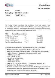
TC1765_ds_v12 (TC1765_ds_v12_1202.pdf) - Infineon
TC1765_ds_v12 (TC1765_ds_v12_1202.pdf) - Infineon
TC1765_ds_v12 (TC1765_ds_v12_1202.pdf) - Infineon
- TAGS
- infineon
- www.infineon.com

You also want an ePaper? Increase the reach of your titles
YUMPU automatically turns print PDFs into web optimized ePapers that Google loves.
<strong>TC1765</strong><br />
Microcontrollers<br />
Data Sheet, V1.2, Dec. 2002<br />
32-Bit Single-Chip Microcontroller<br />
Never stop thinking.
Edition 2002-12<br />
Published by <strong>Infineon</strong> Technologies AG,<br />
St.-Martin-Strasse 53,<br />
81669 München, Germany<br />
© <strong>Infineon</strong> Technologies AG 2002.<br />
All Rights Reserved.<br />
Attention please!<br />
The information herein is given to describe certain components and shall not be considered as warranted<br />
characteristics.<br />
Terms of delivery and rights to technical change reserved.<br />
We hereby disclaim any and all warranties, including but not limited to warranties of non-infringement, regarding<br />
circuits, descriptions and charts stated herein.<br />
<strong>Infineon</strong> Technologies is an approved CECC manufacturer.<br />
Information<br />
For further information on technology, delivery terms and conditions and prices please contact your nearest<br />
<strong>Infineon</strong> Technologies Office in Germany or our <strong>Infineon</strong> Technologies Representatives worldwide<br />
(www.infineon.com).<br />
Warnings<br />
Due to technical requirements components may contain dangerous substances. For information on the types in<br />
question please contact your nearest <strong>Infineon</strong> Technologies Office.<br />
<strong>Infineon</strong> Technologies Components may only be used in life-support devices or systems with the express written<br />
approval of <strong>Infineon</strong> Technologies, if a failure of such components can reasonably be expected to cause the failure<br />
of that life-support device or system, or to affect the safety or effectiveness of that device or system. Life support<br />
devices or systems are intended to be implanted in the human body, or to support and/or maintain and sustain<br />
and/or protect human life. If they fail, it is reasonable to assume that the health of the user or other persons may<br />
be endangered.
<strong>TC1765</strong><br />
Microcontrollers<br />
Data Sheet, V1.2, Dec. 2002<br />
32-Bit Single-Chip Microcontroller<br />
Never stop thinking.
<strong>TC1765</strong> Data Sheet<br />
Preliminary<br />
Revision History: 2002-12 V1.2<br />
Previous Version: V1.1, 2002-10, V1.0, 2002-05<br />
Page Subjects (major changes since last revision)<br />
Changes from V1.1 to V1.2<br />
58, 59 Overshoot conditions (notes 2) and 3) ) for digital supply voltages added<br />
60 Class A pins: input low voltage V ILmin (CMOS) improved; pull-up/pull-down<br />
current spec corrected and completed;<br />
61 Class A pins: pull-up/pull-down current spec corrected and completed;<br />
62 Note 7) inserted<br />
69 Note 3) added to “Sum of IDDS” 80 t30min corrected<br />
83 Package outlines updated (no more “Preliminary” in drawing)<br />
Changes from V1.0 to V1.1<br />
All In general: Data Sheet status changed from “Advance Information” to<br />
“Preliminary”<br />
22 The SSC RXFIFO and TXFIFO are 4-stage FIFOs (not 8-stage)<br />
61 Input hysteresis corrected<br />
62 Footnote 10) added<br />
66 Footnote 8) : word “numeric” added<br />
69 Missing power supply currents now specified<br />
74 Last paragraph modified because of Figure 29 correction<br />
75 Figure 29 corrected and improved<br />
81 t 55 added (min. value) and corrected (max. value)<br />
82 t 61min and t 62min corrected<br />
We Listen to Your Comments<br />
Any information within this document that you feel is wrong, unclear or missing at all?<br />
Your feedback will help us to continuously improve the quality of this document.<br />
Please send your proposal (including a reference to this document) to:<br />
mcdocu.comments@infineon.com
Preliminary<br />
32-Bit Single-Chip Microcontroller<br />
TriCore Family<br />
<strong>TC1765</strong><br />
High Performance 32-bit TriCore CPU with 4-Stage Pipeline<br />
– 25 ns Instruction Cycle Time at 40 MHz CPU/System Clock<br />
Dual Issue super-scalar implementation<br />
– Instruction triple issue<br />
Circular Buffer and bit-reverse addressing modes for DSP algorithms<br />
Flexible multi-master interrupt system<br />
Very fast interrupt response time<br />
Hardware controlled context switch for task switch and interrupts<br />
48 Kbytes of on-chip SRAM for data and time critical code<br />
8-channel DMA Controller for FPI Bus transactions<br />
Built-in calibration support<br />
On-chip Flexible Peripheral Interface Bus (FPI Bus) for interconnections of functional<br />
units<br />
External Bus Interface Unit (EBU) with dedicated pins used for<br />
– Communication with external data memories and peripheral units<br />
– Instruction fetches from external Burst Flash program memories<br />
On-Chip Peripheral Units<br />
– General Purpose Timer Array (GPTA) with a powerful set of digital signal filtering<br />
and timer functionality to realize autonomous and complex I/O management<br />
– Multifunctional General Purpose Timer Unit (GPTU) with three 32-bit timer/counters<br />
– Two Asynchronous/Synchronous Serial Channels (ASC0, ASC1) with baudrate<br />
generator, parity, framing and overrun error detection<br />
– Two High Speed Synchronous Serial Channels (SSC0, SSC1) with programmable<br />
data length and shift direction<br />
– TwinCAN Module with two interconnected CAN nodes for high efficiency data<br />
handling via FIFO buffering and gateway data transfer<br />
– Two Analog-to-Digital Converter Units (ADC0, ADC1) with 8-bit, 10-bit, or 12-bit<br />
resolution and 24 analog inputs<br />
– Watchdog Timer and System Timer<br />
77 digital general purpose I/O lines and one 24-bit analog port<br />
On-chip Debug Support<br />
Power Management System<br />
Clock Generation Unit with PLL<br />
Two derivatives with upward compatible pin configuration<br />
– <strong>TC1765</strong>N<br />
– <strong>TC1765</strong>T (with additional 16-bit OCDS Level 2 trace port)<br />
Ambient temperature under bias: -40 °C to +125 °C<br />
P-LBGA-260 package<br />
Data Sheet 1 V1.2, 2002-12
Preliminary<br />
<strong>TC1765</strong><br />
Ordering Information<br />
The ordering code for <strong>Infineon</strong> microcontrollers provides an exact reference to the<br />
required product. This ordering code identifies: the derivative itself, i.e. its function set,<br />
the temperature range, and the package and the type of delivery.<br />
The <strong>TC1765</strong> is available with the following ordering code:<br />
Type Ordering Code Package Description<br />
SAK-<strong>TC1765</strong>N-L40EB Q67121-C2326 P-LBGA-260 32-Bit Single-Chip<br />
Microcontroller<br />
40 MHz, -40 °C to +125 °C<br />
SAK-<strong>TC1765</strong>T-L40EB Q67121-C2348 P-LBGA-260 32-Bit Single-Chip<br />
Microcontroller<br />
40 MHz, -40 °C to +125 °C<br />
(with OCDS2 trace port)<br />
Data Sheet 2 V1.2, 2002-12
Preliminary<br />
Block Diagram<br />
PMU<br />
(Program Memory Unit)<br />
TriCore<br />
CPU<br />
128 64<br />
max. 40 MHz<br />
DMU<br />
(Data Memory Unit)<br />
V DDSBRAM<br />
V DDRAM<br />
8 KB Boot ROM<br />
16 KB Scratch Pad RAM<br />
1 KB Instruction Cache<br />
32 KB SRAM<br />
16<br />
TracePort<br />
Interrupt<br />
Trace &<br />
OCDS<br />
16<br />
TP<br />
V DDOSC<br />
V SSOSC<br />
32<br />
CPUCLK<br />
XTAL1<br />
XTAL2<br />
ECIN<br />
ECOUT<br />
OSC<br />
F<br />
P<br />
I<br />
JTAG &<br />
Cerberus<br />
(<strong>TC1765</strong>T only)<br />
OCDS 3<br />
Control<br />
Control<br />
5<br />
5<br />
JTAG IO<br />
Analog<br />
10<br />
Power<br />
Supply<br />
Figure 1 <strong>TC1765</strong> Block Diagram<br />
32<br />
STM BCU PLL<br />
Data<br />
[31:0]<br />
32<br />
SCU<br />
Power-<br />
Watchdog-<br />
Reset<br />
Sys. Cntrl.<br />
DMA<br />
Controller<br />
EBU<br />
(External<br />
Bus<br />
Unit)<br />
<strong>TC1765</strong><br />
Data Sheet 3 V1.2, 2002-12<br />
FPI Bus<br />
B<br />
u<br />
s<br />
16<br />
ADC1<br />
Address<br />
[23:0]<br />
24<br />
Twin<br />
CAN<br />
SSC0<br />
ASC1<br />
GPTA<br />
Analog Input Connection<br />
24<br />
AN<br />
[23:0]<br />
Chip<br />
Select<br />
5<br />
16<br />
SSC1<br />
ASC0<br />
GPTU<br />
ADC0<br />
EBU<br />
Control<br />
10<br />
8<br />
3<br />
Port 4<br />
8<br />
5<br />
V DDP<br />
10 23<br />
4<br />
3<br />
2<br />
5<br />
3<br />
2<br />
2<br />
7<br />
3<br />
2<br />
16<br />
16<br />
3<br />
2<br />
16<br />
V SS<br />
V DD<br />
Port 0<br />
Port 5<br />
Port 1<br />
Port 2<br />
Port 3<br />
16 5<br />
16<br />
16<br />
16<br />
MCB04989
Preliminary<br />
Logic Symbol<br />
General<br />
Control<br />
Oscillator<br />
JTAG / OCDS<br />
Digital Circuitry<br />
Power Supply<br />
ADC Analog<br />
Power Supply<br />
TESTMODE<br />
HDRST<br />
PORST<br />
NMI<br />
BYPASS<br />
XTAL1<br />
XTAL2<br />
V DDOSC<br />
V SSOSC<br />
CPUCLK<br />
TRST<br />
TCK<br />
TDI<br />
TDO<br />
TMS<br />
OCDSE<br />
BRKIN<br />
BRKOUT<br />
TP [15:0]<br />
(<strong>TC1765</strong>T only)<br />
V DDP<br />
V DD<br />
V SS<br />
V DDRAM<br />
V DDSBRAM<br />
V DDM<br />
V SSM<br />
Figure 2 <strong>TC1765</strong> Logic Symbol<br />
5<br />
10<br />
23<br />
<strong>TC1765</strong>T<br />
<strong>TC1765</strong>N<br />
D[31:0]<br />
A[23:0]<br />
Chip<br />
Select<br />
Port 0<br />
16-Bit<br />
Port 1<br />
16-Bit<br />
Port 2<br />
16-Bit<br />
Port 3<br />
16-Bit<br />
Port 4<br />
8-Bit<br />
Port 5<br />
5-Bit<br />
AN[23:0]<br />
V AREF0<br />
V AGND0<br />
V DDA0<br />
V SSA0<br />
V AREF1<br />
V AGND1<br />
V DDA1<br />
V SSA1<br />
External<br />
Bus Interface<br />
<strong>TC1765</strong><br />
Alternate Functions<br />
GPTU / ASC0 /<br />
SSC0 / CAN /<br />
ADC0 / ADC1<br />
GPTA<br />
GPTA /<br />
CFG<br />
ASC1<br />
SSC1<br />
ADC<br />
Analog Inputs<br />
ADC0 Analog<br />
Power Supply<br />
ADC1 Analog<br />
Power Supply<br />
MCA04973<br />
Data Sheet 4 V1.2, 2002-12<br />
5<br />
10<br />
Control<br />
ECIN<br />
ECOUT
Preliminary<br />
Pin Configuration<br />
A<br />
B<br />
C<br />
D<br />
E<br />
F<br />
G<br />
H<br />
J<br />
K<br />
L<br />
M<br />
N<br />
P<br />
R<br />
T<br />
U<br />
V<br />
1 2 3 4 5 6 7 8 9 10 11 12 13 14 15 16 17 18<br />
AN<br />
17<br />
AN<br />
19<br />
V AREF1<br />
V SSA1<br />
D29<br />
D28<br />
AN<br />
16<br />
AN<br />
18<br />
AN<br />
20<br />
AN<br />
23<br />
V AGND1<br />
D30<br />
D27 D26<br />
D23 D22<br />
D20<br />
D17<br />
D16<br />
D15<br />
EC<br />
IN<br />
EC<br />
OUT<br />
D4<br />
RD<br />
D21<br />
D18<br />
V DD<br />
D13<br />
D12<br />
V DD<br />
AN<br />
8<br />
AN<br />
11<br />
AN<br />
10<br />
AN<br />
12<br />
AN<br />
15<br />
AN<br />
22<br />
V DD<br />
RAM<br />
D25<br />
V DD<br />
D19<br />
D14<br />
D11<br />
D9<br />
AN<br />
9<br />
AN<br />
13<br />
AN<br />
14<br />
AN<br />
21<br />
V DDA1<br />
D31<br />
D24<br />
D10<br />
D8<br />
D3 D5 D1<br />
RD/<br />
WR<br />
ADV BC0<br />
BC1<br />
BC3<br />
D7<br />
D0<br />
BC2<br />
CODE<br />
V SSM<br />
V DDM<br />
V SS<br />
D6<br />
D2<br />
V DD<br />
BAA<br />
A1<br />
AN<br />
7<br />
AN<br />
5<br />
AN<br />
6<br />
AN<br />
3<br />
WAIT/<br />
IN D<br />
A0<br />
A2<br />
A4<br />
AN<br />
4<br />
AN<br />
2<br />
V AGND0<br />
AN<br />
1<br />
A3<br />
A6<br />
A7<br />
A9<br />
AN<br />
0<br />
V SSA0<br />
P0.3<br />
P0.1<br />
TP.0 TP.1<br />
TP.2<br />
V SS<br />
V SS<br />
TP.4<br />
TP.6<br />
A5<br />
A11<br />
A10<br />
V DD<br />
V AREF0<br />
1 2 3 4 5 6 7 8 9 10 11 12 13 14 15 16 17 18<br />
Figure 3 <strong>TC1765</strong> Pinning for P-LBGA-260 Package (top view)<br />
P0.2<br />
V DDP<br />
P0.6<br />
TP.3<br />
V SS<br />
V SS<br />
TP.5<br />
TP.7<br />
A8<br />
A15 A16<br />
A14 A18 A23 CS0<br />
A13<br />
A12<br />
V DDA0<br />
P0.7<br />
P0.11<br />
V SS<br />
V SS<br />
V SS<br />
V SS<br />
V SS<br />
V SS<br />
V SS<br />
A19<br />
CSEMU/<br />
V A22 CSOVL CS1 A20 A17 TMS<br />
TEST<br />
DD N.C. N.C.<br />
MODE<br />
<strong>TC1765</strong><br />
MCP05009<br />
Data Sheet 5 V1.2, 2002-12<br />
P0.0<br />
P0.9<br />
P0.12<br />
P0.13<br />
V SS<br />
V SS<br />
V SS<br />
V SS<br />
V SS<br />
V SS<br />
CS3<br />
CS2<br />
P0.4 P0.5<br />
P0.15<br />
P5.3<br />
V DD<br />
TP.14 TP.15<br />
TP.12<br />
V SS<br />
V SS<br />
TP.10<br />
TP.8<br />
OCD<br />
SE<br />
A21<br />
V DD<br />
V DDP<br />
P4.7<br />
P5.0<br />
TP.13<br />
V SS<br />
V SS<br />
TP.11<br />
TP.9<br />
TDO<br />
BRK<br />
OUT<br />
P0.8<br />
P5.1 P5.2<br />
P4.1<br />
P4.5<br />
CPU<br />
CLK<br />
TCK<br />
V DD<br />
The Trace port is only available in the <strong>TC1765</strong>T.<br />
P0.10<br />
P3.12<br />
P4.0<br />
TRST<br />
TDI<br />
P0.14<br />
P4.3<br />
P4.6<br />
P3.13<br />
P3.4 P3.3 P3.5<br />
P3.1<br />
P2.12 P2.14 P2.13<br />
P2.11<br />
P2.8<br />
V SS<br />
P1.14<br />
P2.7<br />
P2.2<br />
P1.5<br />
BRK<br />
IN<br />
P1.15<br />
P1.11<br />
P1.10<br />
P1.4<br />
P1.8<br />
P1.2 P1.1<br />
P2.1<br />
P5.4<br />
P3.15<br />
P4.4<br />
V DDP<br />
P3.0<br />
P2.9<br />
P2.5<br />
P2.6<br />
P1.9<br />
P4.2<br />
P3.14<br />
P3.9<br />
P3.7<br />
V DD<br />
V DDP<br />
P2.3<br />
P1.12<br />
V DDP<br />
P1.3<br />
BY<br />
PASS<br />
V DD<br />
SBRAM<br />
V SS<br />
OSC<br />
PO<br />
RST<br />
NMI<br />
P3.11<br />
P3.10<br />
P3.8<br />
P3.6<br />
P3.2<br />
P2.15<br />
P2.10<br />
P2.4<br />
P2.0<br />
P1.13<br />
P1.7<br />
P1.6<br />
P1.0<br />
HD<br />
RST<br />
V DD<br />
OSC<br />
XTAL<br />
2<br />
XTAL<br />
1<br />
A<br />
B<br />
C<br />
D<br />
E<br />
F<br />
G<br />
H<br />
J<br />
K<br />
L<br />
M<br />
N<br />
P<br />
R<br />
T<br />
U<br />
V
Preliminary<br />
<strong>TC1765</strong><br />
Table 1 Pin Definitions and Functions<br />
Symbol Pin In<br />
Out<br />
Functions<br />
D[31:0]<br />
EBU Data Bus Lines<br />
D0 T3 I/O<br />
D1 R4 I/O<br />
D2 P4 I/O<br />
D3 R2 I/O<br />
D4 R1 I/O<br />
D5 R3 I/O<br />
D6 N4 I/O<br />
D7 P3 I/O<br />
D8 M4 I/O<br />
D9 N3 I/O<br />
D10 L4 I/O<br />
D11 M3 I/O<br />
D12 N2 I/O<br />
D13 M2 I/O<br />
D14 L3 I/O<br />
D15 M1 I/O<br />
D16 L1 I/O<br />
D17 K1 I/O<br />
D18 K2 I/O<br />
D19 K3 I/O<br />
D20 J1 I/O<br />
D21 J2 I/O<br />
D22 H2 I/O<br />
D23 H1 I/O<br />
D24 J4 I/O<br />
D25 H3 I/O<br />
D26 G2 I/O<br />
D27 G1 I/O<br />
D28 F1 I/O<br />
D29 E1 I/O<br />
D30 F2 I/O<br />
D31 H4 I/O<br />
1)2)<br />
The EBU Data Bus Lines D[31:0] serve as external data bus.<br />
Data bus line 0<br />
Data bus line 1<br />
Data bus line 2<br />
Data bus line 3<br />
Data bus line 4<br />
Data bus line 5<br />
Data bus line 6<br />
Data bus line 7<br />
Data bus line 8<br />
Data bus line 9<br />
Data bus line 10<br />
Data bus line 11<br />
Data bus line 12<br />
Data bus line 13<br />
Data bus line 14<br />
Data bus line 15<br />
Data bus line 16<br />
Data bus line 17<br />
Data bus line 18<br />
Data bus line 19<br />
Data bus line 20<br />
Data bus line 21<br />
Data bus line 22<br />
Data bus line 23<br />
Data bus line 24<br />
Data bus line 25<br />
Data bus line 26<br />
Data bus line 27<br />
Data bus line 28<br />
Data bus line 29<br />
Data bus line 30<br />
Data bus line 31<br />
Data Sheet 6 V1.2, 2002-12
Preliminary<br />
Table 1 Pin Definitions and Functions (cont’d)<br />
Symbol Pin In<br />
Out<br />
Functions<br />
A[23:0]<br />
A0<br />
A1<br />
A2<br />
A3<br />
A4<br />
A5<br />
A6<br />
A7<br />
A8<br />
A9<br />
A10<br />
A11<br />
A12<br />
A13<br />
A14<br />
A15<br />
A16<br />
A17<br />
A18<br />
A19<br />
A20<br />
A21<br />
A22<br />
A23<br />
CS0<br />
CS1<br />
CS2<br />
CS3<br />
CSEMU/<br />
CSOVL<br />
T5<br />
V4<br />
U5<br />
R6<br />
V5<br />
R7<br />
T6<br />
U6<br />
R8<br />
V6<br />
U7<br />
T7<br />
V8<br />
U14<br />
U8<br />
T8<br />
T9<br />
V14<br />
U9<br />
R9<br />
V13<br />
T11<br />
V10<br />
U10<br />
U12<br />
V12<br />
T10<br />
R10<br />
O<br />
O<br />
O<br />
O<br />
O<br />
O<br />
O<br />
O<br />
O<br />
O<br />
O<br />
O<br />
O<br />
O<br />
O<br />
O<br />
O<br />
O<br />
O<br />
O<br />
O<br />
O<br />
O<br />
O<br />
O<br />
O<br />
O<br />
O<br />
<strong>TC1765</strong><br />
EBU Address Bus Lines 3)4)<br />
The EBU Address Bus Lines A[23:0] serve as address bus.<br />
Address bus line 0<br />
Address bus line 1<br />
Address bus line 2<br />
Address bus line 3<br />
Address bus line 4<br />
Address bus line 5<br />
Address bus line 6<br />
Address bus line 7<br />
Address bus line 8<br />
Address bus line 9<br />
Address bus line 10<br />
Address bus line 11<br />
Address bus line 12<br />
Address bus line 13<br />
Address bus line 14<br />
Address bus line 15<br />
Address bus line 16<br />
Address bus line 17<br />
Address bus line 18<br />
Address bus line 19<br />
Address bus line 20<br />
Address bus line 21<br />
Address bus line 22<br />
Address bus line 23<br />
Chip Select Lines 3)5)<br />
Chip select output line 0<br />
Chip select output line 1<br />
Chip select output line 2<br />
Chip select output line 3<br />
V11 O Chip Select for Emulator Region / Chip Select for<br />
Emulator Overlay Memory 3)5)<br />
Data Sheet 7 V1.2, 2002-12
Preliminary<br />
Table 1 Pin Definitions and Functions (cont’d)<br />
Symbol Pin In<br />
Out<br />
Functions<br />
BC0<br />
BC1<br />
BC2<br />
BC3<br />
RD<br />
RD/WR<br />
ADV<br />
WAIT/IND<br />
BAA<br />
CODE<br />
U2<br />
V1<br />
U3<br />
V2<br />
T1<br />
T2<br />
U1<br />
R5<br />
U4<br />
V3<br />
O<br />
O<br />
O<br />
O<br />
O<br />
O<br />
O<br />
I<br />
O<br />
O<br />
<strong>TC1765</strong><br />
EBU Control Lines 1)5)<br />
The EBU control lines are required for controlling external<br />
memory or peripheral devices.<br />
Byte control line 0<br />
Byte control line 1<br />
Byte control line 2<br />
Byte control line 3<br />
Read control line<br />
Write control line<br />
Address valid output<br />
Wait input / End of burst input<br />
Burst address advance output<br />
Code fetch status output<br />
The CODE signal has the same timing as the chip select<br />
signals.<br />
Data Sheet 8 V1.2, 2002-12
Preliminary<br />
Table 1 Pin Definitions and Functions (cont’d)<br />
Symbol Pin In<br />
Out<br />
Functions<br />
AN[23:0]<br />
AN0<br />
AN1<br />
AN2<br />
AN3<br />
AN4<br />
AN5<br />
AN6<br />
AN7<br />
AN8<br />
AN9<br />
AN10<br />
AN11<br />
AN12<br />
AN13<br />
AN14<br />
AN15<br />
AN16<br />
AN17<br />
AN18<br />
AN19<br />
AN20<br />
AN21<br />
AN22<br />
AN23<br />
A7<br />
D6<br />
B6<br />
D5<br />
A6<br />
B5<br />
C5<br />
A5<br />
A3<br />
C4<br />
C3<br />
B3<br />
D3<br />
D4<br />
E4<br />
E3<br />
A2<br />
A1<br />
B2<br />
B1<br />
C2<br />
F4<br />
F3<br />
D2<br />
I<br />
I<br />
I<br />
I<br />
I<br />
I<br />
I<br />
I<br />
I<br />
I<br />
I<br />
I<br />
I<br />
I<br />
I<br />
I<br />
I<br />
I<br />
I<br />
I<br />
I<br />
I<br />
I<br />
I<br />
<strong>TC1765</strong><br />
ADC Analog Input Port<br />
The ADC Analog Input Port provides 24 analog input lines for<br />
the A/D converters ADC0 and ADC1.<br />
Analog input 0<br />
Analog input 1<br />
Analog input 2<br />
Analog input 3<br />
Analog input 4<br />
Analog input 5<br />
Analog input 6<br />
Analog input 7<br />
Analog input 8<br />
Analog input 9<br />
Analog input 10<br />
Analog input 11<br />
Analog input 12<br />
Analog input 13<br />
Analog input 14<br />
Analog input 15<br />
Analog input 16<br />
Analog input 17<br />
Analog input 18<br />
Analog input 19<br />
Analog input 20<br />
Analog input 21<br />
Analog input 22<br />
Analog input 23<br />
Data Sheet 9 V1.2, 2002-12
Preliminary<br />
Table 1 Pin Definitions and Functions (cont’d)<br />
Symbol Pin In<br />
Out<br />
Functions<br />
P0<br />
P0.0<br />
P0.1<br />
P0.2<br />
P0.3<br />
P0.4<br />
P0.5<br />
P0.6<br />
P0.7<br />
P0.8<br />
P0.9<br />
P0.10<br />
P0.11<br />
P0.12<br />
P0.13<br />
P0.14<br />
P0.15<br />
A10<br />
D7<br />
B8<br />
C7<br />
A11<br />
A12<br />
D8<br />
B9<br />
A13<br />
B10<br />
A14<br />
C9<br />
C10<br />
D10<br />
A15<br />
B11<br />
I/O<br />
I/O<br />
I<br />
I/O<br />
I<br />
I<br />
I/O<br />
I<br />
I<br />
I/O<br />
I<br />
I/O<br />
O<br />
I/O<br />
O<br />
I/O<br />
O<br />
I/O<br />
O<br />
I/O<br />
I/O<br />
I/O<br />
I<br />
O<br />
I<br />
O<br />
<strong>TC1765</strong><br />
Port 0 6)<br />
Port 0 is a 16-bit bi-directional general purpose I/O port that<br />
is also used as input/output for ASC0, SSC0, CAN, GPTU,<br />
ADC0, ADC1, and the DMA Controller.<br />
GPT0 GPTU I/O line 0 /<br />
AD0EXTIN0 ADC0 external trigger input 0<br />
GPT1 GPTU I/O line 1<br />
AD0EXTIN1 ADC0 external trigger input 1<br />
DMREQ0A DMA request input 0A<br />
GPT2 GPTU I/O line 2<br />
AD1EXTIN0 ADC1 external trigger input 0<br />
DMREQ1A DMA request input 1A<br />
GPT3 GPTU I/O line 3<br />
AD1EXTIN1 ADC1 external trigger input 1<br />
GPT4 GPTU I/O line 4 /<br />
AD0EMUX0 ADC0 external multiplexer control 0<br />
GPT5 GPTU I/O line 5<br />
AD0EMUX1 ADC0 external multiplexer control 1<br />
GPT6 GPTU I/O line 6<br />
AD0EMUX2 ADC0 external multiplexer control 2<br />
RXD0 ASC0 receiver input/output<br />
TXD0 ASC0 transmitter output<br />
SCLK0 SSC0 clock input/output<br />
MRST0 SSC0 master receive input /<br />
SSC0 slave transmit output<br />
MTSR0 SSC0 master transmit output /<br />
SSC0 slave receive input<br />
RXDCAN0 CAN receiver input 0<br />
TXDCAN0 CAN transmitter output 0<br />
RXDCAN1 CAN receiver input 1<br />
TXDCAN1 CAN transmitter output 1<br />
Data Sheet 10 V1.2, 2002-12
Preliminary<br />
Table 1 Pin Definitions and Functions (cont’d)<br />
Symbol Pin In<br />
Out<br />
Functions<br />
P1<br />
P1.0<br />
P1.1<br />
P1.2<br />
P1.3<br />
P1.4<br />
P1.5<br />
P1.6<br />
P1.7<br />
P1.8<br />
P1.9<br />
P1.10<br />
P1.11<br />
P1.12<br />
P1.13<br />
P1.14<br />
P1.15<br />
P2<br />
P2.0<br />
P2.1<br />
P2.2<br />
P2.3<br />
P2.4<br />
P2.5<br />
P2.6<br />
P2.7<br />
P2.8<br />
P2.9<br />
P2.10<br />
P2.11<br />
P2.12<br />
P2.13<br />
P2.14<br />
P2.15<br />
N18<br />
R16<br />
R15<br />
M17<br />
N16<br />
P15<br />
M18<br />
L18<br />
P16<br />
U16<br />
M16<br />
L16<br />
K17<br />
K18<br />
L15<br />
K16<br />
J18<br />
T15<br />
N15<br />
J17<br />
H18<br />
J16<br />
T16<br />
M15<br />
J15<br />
H16<br />
G18<br />
H15<br />
G15<br />
G17<br />
G16<br />
F18<br />
I/O<br />
I/O<br />
I/O<br />
I/O<br />
I/O<br />
I/O<br />
I/O<br />
I/O<br />
I/O<br />
I/O<br />
I/O<br />
I/O<br />
I/O<br />
I/O<br />
I/O<br />
I/O<br />
I/O<br />
I/O<br />
I/O<br />
I/O<br />
I/O<br />
I/O<br />
I/O<br />
I/O<br />
I/O<br />
I/O<br />
I/O<br />
I/O<br />
I/O<br />
I/O<br />
I/O<br />
I/O<br />
I/O<br />
I/O<br />
<strong>TC1765</strong><br />
Port 1 6)<br />
Port 1 is a 16-bit bidirectional general purpose I/O port which<br />
also serves as input or output for the GPTA.<br />
IN0 / OUT0 line of GPTA<br />
IN1 / OUT1 line of GPTA<br />
IN2 / OUT2 line of GPTA<br />
IN3 / OUT3 line of GPTA<br />
IN4 / OUT4 line of GPTA<br />
IN5 / OUT5 line of GPTA<br />
IN6 / OUT6 line of GPTA<br />
IN7 / OUT7 line of GPTA<br />
IN8 / OUT8 line of GPTA<br />
IN09 / OUT9 line of GPTA<br />
IN10 / OUT10 line of GPTA<br />
IN11 / OUT11 line of GPTA<br />
IN12 / OUT12 line of GPTA<br />
IN13 / OUT13 line of GPTA<br />
IN14 / OUT14 line of GPTA<br />
IN15 / OUT15 line of GPTA<br />
Port 2 6)<br />
Port 2 is a 16-bit bidirectional general purpose I/O port which<br />
also serves as input or output for the GPTA.<br />
IN16 / OUT16 line of GPTA<br />
IN17 / OUT17 line of GPTA<br />
IN18 / OUT18 line of GPTA<br />
IN19 / OUT19 line of GPTA<br />
IN20 / OUT20 line of GPTA<br />
IN21 / OUT21 line of GPTA<br />
IN22 / OUT22 line of GPTA<br />
IN23 / OUT23 line of GPTA<br />
IN24 / OUT24 line of GPTA<br />
IN25 / OUT25 line of GPTA<br />
IN26 / OUT26 line of GPTA<br />
IN27 / OUT27 line of GPTA<br />
IN28 / OUT28 line of GPTA<br />
IN29 / OUT29 line of GPTA<br />
IN30 / OUT30 line of GPTA<br />
IN31 / OUT31 line of GPTA<br />
Data Sheet 11 V1.2, 2002-12
Preliminary<br />
Table 1 Pin Definitions and Functions (cont’d)<br />
Symbol Pin In<br />
Out<br />
Functions<br />
P3<br />
P3.0<br />
P3.1<br />
P3.2<br />
P3.3<br />
P3.4<br />
P3.5<br />
P3.6<br />
P3.7<br />
P3.8<br />
P3.9<br />
P3.10<br />
P3.11<br />
P3.12<br />
P3.13<br />
P3.14<br />
P3.15<br />
P4<br />
P4.0<br />
P4.1<br />
P4.2<br />
P4.3<br />
P4.4<br />
P4.5<br />
P4.6<br />
P4.7<br />
F16<br />
F15<br />
E18<br />
E16<br />
E15<br />
E17<br />
D18<br />
D17<br />
C18<br />
C17<br />
B18<br />
A18<br />
C14<br />
D15<br />
B17<br />
B16<br />
D14<br />
C13<br />
A17<br />
B15<br />
C16<br />
D13<br />
C15<br />
C12<br />
I/O<br />
I/O<br />
I/O<br />
I/O<br />
I/O<br />
I/O<br />
I/O<br />
I/O<br />
I/O<br />
I/O<br />
I/O<br />
I/O<br />
I/O<br />
I/O<br />
I/O<br />
I/O<br />
I/O<br />
I/O<br />
I/O<br />
I/O<br />
I<br />
I/O<br />
I<br />
I/O<br />
I/O<br />
I/O<br />
I/O<br />
I/O<br />
<strong>TC1765</strong><br />
Port 3 6)<br />
Port 3 is a 16-bit bidirectional general purpose I/O port which<br />
also serves as input or output for the GPTA.<br />
IN32 / OUT32 line of GPTA<br />
IN33 / OUT33 line of GPTA<br />
IN34 / OUT34 line of GPTA<br />
IN35 / OUT35 line of GPTA<br />
IN36 / OUT36 line of GPTA<br />
IN37 / OUT37 line of GPTA<br />
IN38 / OUT38 line of GPTA<br />
IN39 / OUT39 line of GPTA<br />
IN40 / OUT40 line of GPTA<br />
IN41 / OUT41 line of GPTA<br />
IN42 / OUT42 line of GPTA<br />
IN43 / OUT43 line of GPTA<br />
IN44 / OUT44 line of GPTA<br />
IN45 / OUT45 line of GPTA<br />
IN46 / OUT46 line of GPTA<br />
IN47 / OUT47 line of GPTA<br />
Port 4 6)<br />
Port 4 is an 8-bit bidirectional general purpose I/O port which<br />
also serves as input/output for the GPTA or external request<br />
input for the DMA controller. During hardware reset the port 4<br />
lines are also used as start-up configuration selection inputs<br />
and PLL clock selection inputs.<br />
IN48 / OUT48 line of GPTA<br />
IN49 / OUT49 line of GPTA /<br />
DMREQ0B DMA request input 0B<br />
IN50 / OUT50 line of GPTA /<br />
DMREQ1B DMA request input 1B<br />
IN51 / OUT51 line of GPTA<br />
IN52 / OUT52 line of GPTA / CFG[0]<br />
IN53 / OUT53 line of GPTA / CFG[1]<br />
IN54 / OUT54 line of GPTA / CFG[2]<br />
IN55 / OUT55 line of GPTA / GPTA emergency shut down<br />
CFG[2:0]: Start-up Configuration Selection Inputs<br />
These pins are sampled during power-on reset (PORST =0).<br />
The configuration inputs define the boot options of the<br />
<strong>TC1765</strong> after a hardware reset operation.<br />
Data Sheet 12 V1.2, 2002-12
Preliminary<br />
Table 1 Pin Definitions and Functions (cont’d)<br />
Symbol Pin In<br />
Out<br />
Functions<br />
P5<br />
P5.0<br />
P5.1<br />
P5.2<br />
P5.3<br />
P5.4<br />
TP<br />
TP.0<br />
TP.1<br />
TP.2<br />
TP.3<br />
TP.4<br />
TP.5<br />
TP.6<br />
TP.7<br />
TP.8<br />
TP.9<br />
TP.10<br />
TP.11<br />
TP.12<br />
TP.13<br />
TP.14<br />
TP.15<br />
TRST 7)<br />
TCK 7)<br />
TDI 8)<br />
D12<br />
B13<br />
B14<br />
C11<br />
A16<br />
G7<br />
G8<br />
H7<br />
H8<br />
L7<br />
L8<br />
M7<br />
M8<br />
M11<br />
M12<br />
L11<br />
L12<br />
H11<br />
H12<br />
G11<br />
G12<br />
I/O<br />
I/O<br />
I<br />
O<br />
I<br />
I/O<br />
I/O<br />
I/O<br />
O<br />
O<br />
O<br />
O<br />
O<br />
O<br />
O<br />
O<br />
O<br />
O<br />
O<br />
O<br />
O<br />
O<br />
O<br />
O<br />
O<br />
<strong>TC1765</strong><br />
Port 56) Port 5 is a 5-bit bidirectional general purpose I/O port which<br />
also serves as input or output for ASC1 and SSC1.<br />
RXD1 ASC1 receiver input/output<br />
DMREQ0C DMA request input 0C<br />
TXD1 ASC1 transmitter output<br />
DMREQ1C DMA request input 1C<br />
SCLK1 SSC1 clock input/output<br />
MRST1 SSC1 master receive input /<br />
SSC1 slave transmit output<br />
MTSR1 SSC1 master transmit output /<br />
SSC1 slave receive input<br />
OCDS-2 Trace Port 3)<br />
TP is the OCDS Level 2 Trace Port. The Trace port is only<br />
available in the <strong>TC1765</strong>T. The TP outputs are tristated during<br />
reset and deep sleep mode.<br />
Trace output 0<br />
Trace output 1<br />
Trace output 2<br />
Trace output 3<br />
Trace output 4<br />
Trace output 5<br />
Trace output 6<br />
Trace output 7<br />
Trace output 8<br />
Trace output 9<br />
Trace output 10<br />
Trace output 11<br />
Trace output 12<br />
Trace output 13<br />
Trace output 14<br />
Trace output 15<br />
R14 I JTAG Module Reset/Enable Input<br />
A low level at this pin resets and disables the JTAG module.<br />
A high level enables the JTAG module.<br />
T13 I JTAG Module Clock Input<br />
T14 I JTAG Module Serial Data Input<br />
Data Sheet 13 V1.2, 2002-12
Preliminary<br />
Table 1 Pin Definitions and Functions (cont’d)<br />
Symbol Pin In<br />
Out<br />
Functions<br />
TDO R12 O JTAG Module Serial Data Output 3)<br />
TMS 8)<br />
<strong>TC1765</strong><br />
V15 I JTAG Module State Machine Control Input<br />
OCDSE 8) R11 I OCDS Enable Input<br />
A low level on this pin during power-on reset (PORST =0)<br />
enables the on-chip debug support (OCDS). In addition, the<br />
level of this pin during power-on reset determines the boot<br />
configuration.<br />
BRKIN 8)<br />
U15 I OCDS Break Input<br />
A low level on this pin causes a break in the chip’s execution<br />
when the OCDS is enabled. In addition, the level of this pin<br />
during power-on reset determines the boot configuration.<br />
BRKOUT T12 O OCDS Break Output 3)<br />
A low level on this pin indicates that a programmable OCDS<br />
event has occurred.<br />
NMI 8)<br />
U17 I Non-Maskable Interrupt Input<br />
A high-to-low transition on this pin causes an NMI-Trap<br />
request to the CPU.<br />
HDRST 8)<br />
P18 I/O Hardware Reset Input / Reset Indication Output 6)<br />
Assertion of this open-drain bidirectional pin causes a<br />
synchronous reset of the chip through external circuitry.<br />
The internal reset circuitry drives this pin in response to a<br />
power-on, hardware, watchdog and power-down wake-up<br />
reset for a specific period of time. For a software reset, it is<br />
programmable whether this pin is activated or not.<br />
PORST T17 I Power-on Reset Input<br />
A low level on PORST causes an asynchronous reset of the<br />
entire chip. During power-up of the <strong>TC1765</strong>, this pin must be<br />
held active (low).<br />
BYPASS N17 I PLL Bypass Control Input<br />
This pin is sampled during power-on reset (PORST = 0). If<br />
BYPASS is at high level, direct drive mode operation of the<br />
clock circuitry is selected and the PLL is bypassed.<br />
Data Sheet 14 V1.2, 2002-12
Preliminary<br />
Table 1 Pin Definitions and Functions (cont’d)<br />
Symbol Pin In<br />
Out<br />
Functions<br />
XTAL1<br />
XTAL2<br />
U18<br />
T18<br />
I<br />
O<br />
ECOUT P1 O EBU Clock Output 3)<br />
<strong>TC1765</strong><br />
Oscillator/PLL/Clock Generator Input/Output Pins<br />
XTAL1 is the input to the oscillator amplifier and input to the<br />
internal clock generator. XTAL2 is the output of the oscillator<br />
amplifier circuit. For clocking the device from an external<br />
source, XTAL1 is driven with the clock signal while XTAL2 is<br />
left unconnected. For crystal oscillator operation XTAL1 and<br />
XTAL2 are connected to the crystal with the appropriate<br />
recommended oscillator circuitry.<br />
ECIN N1 – EBU Clock Input<br />
The ECIN pin is used to latch the data from external<br />
components into the EBU. This pin has to be connected to the<br />
ECOUT pin. Additional delay elements might be used to<br />
adapt to long delays at the address and data lines.<br />
CPUCLK R13 O CPU Clock Output3) General purpose clock output (can be disabled if not used). In<br />
addition, the OCDS-2 trace output data are synchronous to<br />
this clock.<br />
TEST<br />
MODE 8)<br />
V16 I Test Mode Select Input<br />
For normal operation of the <strong>TC1765</strong> this pin should be<br />
connected to V DD.<br />
V DDOSC R18 – Main Oscillator Power Supply (2.5 V) 9)<br />
V SSOSC R17 – Main Oscillator Ground<br />
V DD<br />
J3,<br />
P2,<br />
T4,<br />
V7,<br />
U11,<br />
U13,<br />
L2,<br />
F17,<br />
D11,<br />
V9<br />
– Core and EBU Power Supply (2.5 V) 9)<br />
Data Sheet 15 V1.2, 2002-12
Preliminary<br />
Table 1 Pin Definitions and Functions (cont’d)<br />
Symbol Pin In<br />
Out<br />
Functions<br />
V DDP<br />
L17,<br />
H17,<br />
D16,<br />
B12,<br />
C8<br />
<strong>TC1765</strong><br />
– Port 0 to 5 and Dedicated Pins Power Supply (3.3 - 5 V) 10)<br />
V DDRAM G3 – Power Supply for PMU Memories (2.5 V) 9)<br />
V DDSBRAM P17 – Power Supply for DMU Memory (2.5 V) 9)<br />
Used for normal and stand-by operating mode.<br />
V SS<br />
D9,<br />
K4,<br />
K15,<br />
G9,<br />
G10,<br />
H9,<br />
H10,<br />
J7,<br />
J8,<br />
J9,<br />
J10,<br />
J11,<br />
J12,<br />
K7,<br />
K8,<br />
K9,<br />
K10,<br />
K11,<br />
K12,<br />
L9,<br />
L10,<br />
M9,<br />
M10<br />
– Ground<br />
Data Sheet 16 V1.2, 2002-12
Preliminary<br />
Table 1 Pin Definitions and Functions (cont’d)<br />
Symbol Pin In<br />
Out<br />
Functions<br />
V DDM B4 – ADC Analog Part Power Supply (5 V) 10)<br />
V SSM A4 – ADC Analog Part Ground for V DDM<br />
V DDA0 A9 – ADC0 Analog Part Power Supply (2.5 V) 9)<br />
V SSA0 B7 – ADC0 Analog Part Ground for V DDA0<br />
V DDA1 G4 – ADC1 Analog Part Power Supply (2.5 V) 9)<br />
V SSA1 D1 – ADC1 Analog Part Ground for V DDA1<br />
V AREF0 A8 – ADC0 Reference Voltage 10)<br />
V AGND0 C6 – ADC0 Reference Ground<br />
V AREF1 C1 – ADC1 Reference Voltage 10)<br />
V AGND1 E2 – ADC1 Reference Ground 10)<br />
N.C. V17,<br />
V18<br />
– Not Connected; reserved for future expansions<br />
1) These pins have a drive capability of 600 µA when used as outputs.<br />
2) These pins can be connected with internal pull-up devices by setting bit SCU_CON.EBUDPEN.<br />
3) These outputs have a drive capability of 600 µA.<br />
4) These pins can be connected with internal pull-up devices by setting bit SCU_CON.EBUAPEN.<br />
5) These pins can be connected with internal pull-up devices by setting bit SCU_CON.EBUCPEN.<br />
6) These pins have a drive capability of 2.4 mA when used as outputs.<br />
7) These pins have an internal pull-down device connected.<br />
8) These pins have an internal pull-up device connected.<br />
<strong>TC1765</strong><br />
9) The voltage on power supply pins marked with 10) has to be raised earlier or at least at the same time (= time<br />
window of 1 µs) than on power supply pins marked with 9) (details see power supply section on Page 54).<br />
10) See note 9) .<br />
Data Sheet 17 V1.2, 2002-12
Preliminary<br />
<strong>TC1765</strong><br />
Parallel Ports<br />
The <strong>TC1765</strong> has 77 digital input/output port lines organized into four parallel 16-bit ports<br />
(Port 0 to Port 3), one 8-bit port (Port 4), and one 5-bit port (Port 5). Additionally,<br />
24 analog input port lines are available. The External Bus Unit (EBU) is provided with<br />
dedicated data, address, and control lines. A 16-bit Trace Port is available only in the<br />
<strong>TC1765</strong>T.<br />
The digital parallel ports Port 0 to Port 5 can be all used as general purpose I/O lines or<br />
they can perform input/output functions for the on-chip peripheral units. The on-chip<br />
External Bus Interface Unit allows to communicate with external memories, external<br />
peripherals, or external debugging devices. An overview on the port-to-peripheral unit<br />
assignment is shown in Figure 4.<br />
Note: For further details on the three pin classes of the <strong>TC1765</strong> I/O pins see also Table 8<br />
on Page 56):<br />
External Bus Interface<br />
Data Bus D[31:0]<br />
Address Bus A[23:0]<br />
Control Lines<br />
TP[15:0]<br />
OCDS Trace Port<br />
(<strong>TC1765</strong>T only)<br />
<strong>TC1765</strong>N<br />
<strong>TC1765</strong>T<br />
Parallel<br />
Ports<br />
AN[23:0]<br />
Figure 4 Parallel Ports of the <strong>TC1765</strong><br />
GPIO Alternate Functions<br />
Port 0 GPTU / ASC0 / SSC0 /<br />
CAN / ADC0 / ADC1<br />
Port 1<br />
Port 2<br />
Port 3<br />
Port 4<br />
Port 5<br />
GPTA<br />
GPTA<br />
GPTA<br />
GPTA / CFG<br />
ASC1 / SSC1<br />
MCA04981<br />
Data Sheet 18 V1.2, 2002-12
Preliminary<br />
Serial Interfaces<br />
The <strong>TC1765</strong> includes five serial peripheral interface units:<br />
– Two Asynchronous/Synchronous Serial Interfaces (ASC0 and ASC1)<br />
– Two High-Speed Synchronous Serial Interfaces (SSC0 and SSC1)<br />
– One TwinCAN Interface<br />
<strong>TC1765</strong><br />
Asynchronous/Synchronous Serial Interfaces<br />
Figure 5 shows a global view of the functional blocks of the two Asynchronous/<br />
Synchronous Serial interfaces ASC0 and ASC1.<br />
Clock<br />
Control<br />
Address<br />
Decoder<br />
Interrupt<br />
Control<br />
To DMA<br />
Clock<br />
Control<br />
Address<br />
Decoder<br />
Interrupt<br />
Control<br />
To DMA<br />
f ASC0<br />
EIR<br />
TBIR<br />
TIR<br />
RIR<br />
f ASC1<br />
EIR<br />
TBIR<br />
TIR<br />
RIR<br />
ASC0<br />
Module<br />
(Kernel)<br />
ASC1<br />
Module<br />
(Kernel)<br />
RXD0<br />
TXD0<br />
RXD1<br />
TXD1<br />
Port 0<br />
Control<br />
Port 5<br />
Control<br />
Figure 5 General Block Diagram of the ASC Interfaces<br />
P0.7 /<br />
RXD0<br />
P0.8 /<br />
TXD0<br />
P5.0 /<br />
RXD1<br />
P5.1 /<br />
TXD1<br />
MCB05050<br />
Data Sheet 19 V1.2, 2002-12
Preliminary<br />
<strong>TC1765</strong><br />
Each ASC module, ASC0 and ASC1, communicates with the external world via two I/O<br />
lines. The RXD line is the receive data input signal (in Synchronous Mode also output).<br />
TXD is the transmit output signal. Clock control, address decoding, and interrupt service<br />
request control are managed outside the ASC module kernel.<br />
The Asynchronous/Synchronous Serial Interfaces provide serial communication<br />
between the <strong>TC1765</strong> and other microcontrollers, microprocessors, or external<br />
peripherals.<br />
The ASC supports full-duplex asynchronous communication and half-duplex<br />
synchronous communication. In Synchronous Mode, data is transmitted or received<br />
synchronous to a shift clock which is generated by the ASC internally. In Asynchronous<br />
Mode, 8-bit or 9-bit data transfer, parity generation, and the number of stop bits can be<br />
selected. Parity, framing, and overrun error detection are provided to increase the<br />
reliability of data transfers. Transmission and reception of data are double-buffered. For<br />
multiprocessor communication, a mechanism is included to distinguish address bytes<br />
from data bytes. Testing is supported by a loop-back option. A 13-bit baud rate generator<br />
provides the ASC with a separate serial clock signal that can be very accurately adjusted<br />
by a prescaler implemented as a fractional divider.<br />
Features:<br />
Full-duplex asynchronous operating modes<br />
– 8-bit or 9-bit data frames, LSB first<br />
– Parity bit generation/checking<br />
– One or two stop bits<br />
– Baud rate from 2.5 Mbit/s to 0.6 Bit/s (@ 40 MHz clock)<br />
– Multiprocessor mode for automatic address/data byte detection<br />
– Loop-back capability<br />
Half-duplex 8-bit synchronous operating mode<br />
– Baud rate from 5 Mbit/s to 406.9 Bit/s (@ 40 MHz clock)<br />
Double buffered transmitter/receiver<br />
Interrupt generation<br />
– On a transmitter buffer empty condition<br />
– On a transmit last bit of a frame condition<br />
– On a receiver buffer full condition<br />
– On an error condition (frame, parity, overrun error)<br />
Data Sheet 20 V1.2, 2002-12
Preliminary<br />
<strong>TC1765</strong><br />
High-Speed Synchronous Serial Interfaces<br />
Figure 6 shows a global view of the functional blocks of the two High-Speed<br />
Synchronous Serial interfaces SSC0 and SSC1.<br />
Clock<br />
Control<br />
Address<br />
Decoder<br />
Interrupt<br />
Control<br />
To DMA<br />
Clock<br />
Control<br />
Address<br />
Decoder<br />
Interrupt<br />
Control<br />
To DMA<br />
f SSC0<br />
EIR<br />
TIR<br />
RIR<br />
f SSC1<br />
EIR<br />
TIR<br />
RIR<br />
SSC0<br />
Module<br />
(Kernel)<br />
SSC1<br />
Module<br />
(Kernel)<br />
Figure 6 General Block Diagram of the SSC Interfaces<br />
Master<br />
Slave<br />
SCLK<br />
Master<br />
Slave<br />
SCLK<br />
MCB05051<br />
Each of the SSC modules has three I/O lines, located at Port 0 and Port 5. Each of the<br />
SSC modules is further supplied by separate clock control, interrupt control, address<br />
decoding, and port control logic.<br />
The SSC supports full-duplex and half-duplex serial synchronous communication up to<br />
20 Mbit/s (@ 40 MHz module clock) with receive and transmit FIFO support. The serial<br />
clock signal can be generated by the SSC itself (master mode) or can be received from<br />
an external master (slave mode). Data width, shift direction, clock polarity, and phase are<br />
programmable. This allows communication with SPI-compatible devices. Transmission<br />
RXD<br />
TXD<br />
RXD<br />
TXD<br />
Slave<br />
Master<br />
RXD<br />
TXD<br />
RXD<br />
TXD<br />
Slave<br />
Master<br />
Port 0<br />
Control<br />
Port 5<br />
Control<br />
P0.11 /<br />
MTSR0<br />
P0.10 /<br />
MRST0<br />
P0.9 /<br />
SCLK0<br />
P5.4 /<br />
MTSR1<br />
P5.3 /<br />
MRST1<br />
P5.2 /<br />
SCLK1<br />
Data Sheet 21 V1.2, 2002-12
Preliminary<br />
<strong>TC1765</strong><br />
and reception of data are double-buffered. A 16-bit baud rate generator provides the<br />
SSC with a separate serial clock signal.<br />
Features:<br />
Master and slave mode operation<br />
– Full-duplex or half-duplex operation<br />
Flexible data format<br />
– Programmable number of data bits: 2-bit to 16 bit<br />
– Programmable shift direction: LSB or MSB shift first<br />
– Programmable clock polarity: idle low or high state for the shift clock<br />
– Programmable clock/data phase: data shift with leading or trailing edge of the shift<br />
clock<br />
Baud rate generation from 20 Mbit/s to 305.18 Bit/s (@ 40 MHz module clock)<br />
Interrupt generation<br />
– On a transmitter empty condition<br />
– On a receiver full condition<br />
– On an error condition (receive, phase, baud rate, transmit error)<br />
Three-pin interface<br />
– Flexible SSC pin configuration<br />
4-stage receive FIFO (RXFIFO) and 4-stage transmit FIFO (TXFIFO)<br />
– Independent control of RXFIFO and TXFIFO<br />
– 2 to 16 bit FIFO data width<br />
– Programmable receive/transmit interrupt trigger level<br />
– Receive and transmit FIFO filling level indication<br />
– Overrun error generation<br />
– Underflow error generation<br />
Data Sheet 22 V1.2, 2002-12
Preliminary<br />
TwinCAN Interface<br />
Figure 7 shows a global view of the functional blocks of the TwinCAN module.<br />
Clock<br />
Control<br />
Address<br />
Decoder<br />
Interrupt<br />
Control<br />
f CAN<br />
SR0<br />
SR1<br />
SR2<br />
SR3<br />
SR4<br />
SR5<br />
SR6<br />
SR7<br />
TwinCAN Module Kernel<br />
Interrupt<br />
Control<br />
Bitstream<br />
Processor<br />
Message<br />
Buffers<br />
Timing<br />
Control<br />
Error<br />
Handling<br />
Control<br />
TXDC0<br />
RXDC0<br />
TXDC1<br />
RXDC1<br />
Port<br />
Control<br />
Figure 7 General Block Diagram of the TwinCAN Module<br />
<strong>TC1765</strong><br />
P0.13 /<br />
TXDCAN0<br />
P0.12 /<br />
RXDCAN0<br />
P0.15 /<br />
TXDCAN1<br />
P0.14 /<br />
RXDCAN1<br />
MCB05059<br />
The TwinCAN module has four I/O lines located at Port 0. The TwinCAN module is<br />
further supplied by a clock control, interrupt control, address decoding, and port control<br />
logic.<br />
The TwinCAN module contains two Full-CAN nodes operating independently or<br />
exchanging data and remote frames via a gateway function. Transmission and reception<br />
of CAN frames are handled in accordance to CAN specification V2.0 part B (active).<br />
Each of the two Full-CAN nodes can receive and transmit standard frames with 11-bit<br />
identifiers as well as with extended frames with 29-bit identifiers.<br />
Both CAN nodes share the TwinCAN module’s resources to optimize the CAN bus traffic<br />
handling and to minimize the CPU load. The flexible combination of Full-CAN<br />
functionality and the FIFO architecture reduces the efforts to fulfill the real-time<br />
requirements of complex embedded control applications. Improved CAN bus monitoring<br />
functionality as well as the increased number of message objects permit precise and<br />
convenient CAN bus traffic handling.<br />
Depending on the application, each of the thirty-two message objects can be individually<br />
assigned to one of the two CAN nodes. Gateway functionality allows automatic data<br />
exchange between two separate CAN bus systems, which decreases CPU load and<br />
improves the real time behavior of the entire system.<br />
Data Sheet 23 V1.2, 2002-12
Preliminary<br />
<strong>TC1765</strong><br />
The bit timings for both CAN nodes are derived from the peripheral clock (f CAN) and are<br />
programmable up to a data rate of 1 Mbit/s. A pair of receive and transmit pins connect<br />
each CAN node to a bus transceiver.<br />
Features:<br />
CAN functionality conforms to CAN specification V2.0 B active.<br />
Dedicated control registers are provided for each CAN node.<br />
A data transfer rate up to 1 Mbit/s is supported.<br />
Flexible and powerful message transfer control and error handling capabilities are<br />
implemented.<br />
Full-CAN functionality: 32 message objects can be individually<br />
– Assigned to one of the two CAN nodes<br />
– Configured as transmit or receive object<br />
– Participate in a 2, 4, 8, 16 or 32 message buffer with FIFO algorithm<br />
– Set up to handle frames with 11-bit or 29-bit identifiers<br />
– Provided with programmable acceptance mask register for filtering<br />
– Monitored via a frame counter<br />
– Configured to Remote Monitoring Mode<br />
Up to eight individually programmable interrupt nodes can be used.<br />
CAN Analyzer Mode for bus monitoring is implemented.<br />
Data Sheet 24 V1.2, 2002-12
Preliminary<br />
Timer Units<br />
The <strong>TC1765</strong> includes two timer units:<br />
– General Purpose Timer Unit (GPTU)<br />
– General Purpose Timer Array (GPTA)<br />
General Purpose Timer Unit<br />
Figure 8 shows a global view of the General Purpose Timer Unit (GPTU) module.<br />
Clock<br />
Control<br />
Address<br />
Decoder<br />
Interrupt<br />
Control<br />
Figure 8 General Block Diagram of the GPTU Interface<br />
<strong>TC1765</strong><br />
The GPTU consists of three 32-bit timers designed to solve such application tasks as<br />
event timing, event counting, and event recording. The GPTU communicates with the<br />
external world via eight inputs and eight outputs located at Port 0.<br />
The I/O has three timers (T0, T1, and T2) can operate independently from each other,<br />
or can be combined.<br />
General Features:<br />
f GPTU<br />
SR0<br />
SR1<br />
SR2<br />
SR3<br />
SR4<br />
SR5<br />
SR6<br />
SR7<br />
GPTU<br />
Module<br />
(Kernel)<br />
IN0<br />
IN1<br />
IN2<br />
IN3<br />
IN4<br />
IN5<br />
IN6<br />
IN7<br />
OUT0<br />
OUT1<br />
OUT2<br />
OUT3<br />
OUT4<br />
OUT5<br />
OUT6<br />
OUT7<br />
Port<br />
Control<br />
P0.1 / GPT1<br />
MCB05052<br />
All timers are 32-bit precision timers with a maximum input frequency of f GPTU .<br />
Events generated in T0 or T1 can be used to trigger actions in T2.<br />
Timer overflow or underflow in T2 can be used to clock either T0 or T1.<br />
T0 and T1 can be concatenated to form one 64-bit timer.<br />
Data Sheet 25 V1.2, 2002-12<br />
IO0<br />
IO1<br />
IO2<br />
IO3<br />
IO4<br />
IO5<br />
IO6<br />
IO7<br />
P0.0 / GPT0<br />
P0.2 / GPT2<br />
P0.3 / GPT3<br />
P0.4 / GPT4<br />
P0.5 / GPT5<br />
P0.6 / GPT6<br />
Not Connected
Preliminary<br />
<strong>TC1765</strong><br />
Features of T0 and T1:<br />
Each timer has a dedicated 32-bit reload register with automatic reload on overflow.<br />
Timers can be split into individual 8-, 16-, or 24-bit timers with individual reload<br />
registers.<br />
Overflow signals can be selected to generate service requests, pin output signals, and<br />
T2 trigger events.<br />
Two input pins can define a count option.<br />
Features of T2:<br />
Count up or down is selectable<br />
Operating modes:<br />
– Timer<br />
– Counter<br />
– Quadrature counter (incremental/phase encoded counter interface)<br />
Options:<br />
– External start/stop, one-shot operation, timer clear on external event<br />
– Count direction control through software or an external event<br />
– Two 32-bit reload/capture registers<br />
Reload modes:<br />
– Reload on overflow or underflow<br />
– Reload on external event: positive transition, negative transition, or both transitions<br />
Capture modes:<br />
– Capture on external event: positive transition, negative transition, or both<br />
transitions<br />
– Capture and clear timer on external event: positive transition, negative transition, or<br />
both transitions<br />
Can be split into two 16-bit counter/timers<br />
Timer count, reload, capture, and trigger functions can be assigned to input pins. T0<br />
and T1 overflow events can also be assigned to these functions.<br />
Overflow and underflow signals can be used to trigger T0 and/or T1 and to toggle<br />
output pins.<br />
T2 events are freely assignable to the service request nodes.<br />
Data Sheet 26 V1.2, 2002-12
Preliminary<br />
<strong>TC1765</strong><br />
General Purpose Timer Array<br />
Figure 9 shows a global block diagram of the General Purpose Timer Array (GPTA).<br />
Clock<br />
Control<br />
Address<br />
Decoder<br />
Interrupt<br />
Control<br />
A/D<br />
Converter<br />
f GPTA<br />
SR00<br />
SR01<br />
SR52<br />
SR53<br />
GTC30<br />
To DMA LTC54<br />
PTIN00<br />
PTIN01<br />
PTIN10<br />
PTIN11<br />
GPTA Module Kernel<br />
Clock Generation Unit<br />
Filter &<br />
Prescaler<br />
Cells<br />
Duty Cycle<br />
Measurement<br />
Phase<br />
Discriminator<br />
Logic<br />
Digital Phase<br />
Locked Loop<br />
Signal Generation Unit<br />
Global Timer<br />
Cells<br />
Global<br />
Timers<br />
Local Timer<br />
Cells<br />
Interrupt Control Unit<br />
Figure 9 GPTA Module Block Diagram<br />
Port<br />
Control<br />
IO 54<br />
IO 55<br />
MCB05053<br />
The GPTA module has 56 input signals and 56 output signals which are connected with<br />
56 Port 1, Port 2, Port 3, and Port 4 pins.<br />
The General Purpose Timer Array (GPTA) provides important digital signal filtering and<br />
timer support whose combination enables autonomous and complex functionalities. This<br />
architecture allows easy implementation and easy validation of any kind of timer<br />
functions.<br />
Data Sheet 27 V1.2, 2002-12<br />
IO Sharing Unit with Emergency Shut-Off<br />
IN0<br />
IN1<br />
IN54<br />
IN55<br />
AS0<br />
AS1<br />
AS54<br />
AS55<br />
OUT0<br />
OUT1<br />
OUT54<br />
OUT55<br />
IO0<br />
IO1<br />
IO 14<br />
IO 15<br />
IO 16<br />
IO 17<br />
IO 30<br />
IO 31<br />
IO 32<br />
IO 33<br />
IO 46<br />
IO 47<br />
IO 48<br />
IO 49<br />
P1.0<br />
P1.1<br />
P1.14<br />
P1.15<br />
P2.0<br />
P2.1<br />
P2.14<br />
P2.15<br />
P3.0<br />
P3.1<br />
P3.14<br />
P3.15<br />
P4.0<br />
P4.1<br />
P4.6<br />
P4.7
Preliminary<br />
<strong>TC1765</strong><br />
The General Purpose Timer Array (GPTA) provides a set of hardware modules required<br />
for high speed digital signal processing:<br />
Filter and Prescaler Cells (FPC) support input noise filtering and prescaler operation.<br />
Phase Discrimination Logic units (PDL) decode the direction information output by a<br />
rotation tracking system.<br />
Duty Cycle Measurement Cells (DCM) provide pulse width measurement capabilities.<br />
A Digital Phase Locked Loop unit (PLL) generates a programmable number of GPTA<br />
module clock ticks during an input signal’s period.<br />
Global Timer units (GT) driven by various clock sources are implemented to operate<br />
as a time base for the associated “Global Timer Cells”.<br />
Global Timer Cells (GTC) can be programmed to capture the contents of a Global<br />
Timer on an event that occurred at an external port pin or at an internal FPC output.<br />
A GTC may be also used to control an external port pin with the result of an internal<br />
compare operation. GTCs can be logically concatenated to provide a common<br />
external port pin with a complex signal waveform.<br />
Local Timer Cells (LTC) operating in Timer, Capture, or Compare Mode may be also<br />
logically tied together to drive a common external port pin with a complex signal<br />
waveform. LTCs — enabled in Timer Mode or Capture Mode — can be clocked or<br />
triggered by<br />
– A prescaled GPTA module clock,<br />
– An FPC, PDL, DCM, PLL, or GTC output signal line,<br />
– An external port pin.<br />
Some input lines driven by processor I/O pa<strong>ds</strong> may be shared by a LTC and a GTC cell<br />
to trigger their programmed operation simultaneously.<br />
The following list summarizes all blocks supported:<br />
Clock Generation Unit:<br />
Filter and Prescaler Cell (FPC):<br />
– Six independent units<br />
– Three operating modes (Prescaler, Delayed Debounce Filter, Immediate Debounce<br />
Filter)<br />
– f GPTA down-scaling capability<br />
– f GPTA/2 maximum input signal frequency in Filter Mode<br />
Phase Discriminator Logic (PDL):<br />
– Two independent units<br />
– Two operating modes (2 and 3 sensor signals)<br />
– f GPTA /4 maximum input signal frequency in 2-sensor mode, f GPTA /6 maximum input<br />
signal frequency in 3-sensor mode<br />
Duty Cycle Measurement (DCM):<br />
– Four independent units<br />
– 0 - 100% margin and time-out handling<br />
Data Sheet 28 V1.2, 2002-12
Preliminary<br />
– f GPTA maximum resolution<br />
– f GPTA /2 maximum input signal frequency<br />
Digital Phase Locked Loop (PLL):<br />
– One unit<br />
– Arbitrary multiplication factor between 1 and 65535<br />
– f GPTA maximum resolution<br />
– f GPTA/2 maximum input signal frequency<br />
Signal Generation Unit:<br />
Global Timers (GT):<br />
– Two independent units<br />
– Two operating modes (Free Running Timer and Reload Timer)<br />
– 24-bit data width<br />
– fGPTA maximum resolution<br />
– fGPTA/2 maximum input signal frequency<br />
Global Timer Cell (GTC):<br />
– 32 independent units<br />
– Two operating modes (Capture, Compare and Capture after Compare)<br />
– 24-bit data width<br />
– fGPTA maximum resolution<br />
– fGPTA/2 maximum input signal frequency<br />
Local Timer Cell (LTC):<br />
– 64 independent units<br />
– Three operating modes (Timer, Capture and Compare)<br />
– 16-bit data width<br />
– fGPTA maximum resolution<br />
– fGPTA/2 maximum input signal frequency<br />
Interrupt Control Unit:<br />
111 interrupt sources generating 54 service requests<br />
I/O Sharing Unit:<br />
Interconnecting input and output lines from FPC, GTC, LTC and ports<br />
Emergency function<br />
<strong>TC1765</strong><br />
Data Sheet 29 V1.2, 2002-12
Preliminary<br />
<strong>TC1765</strong><br />
Analog-to-Digital Converters<br />
The two on-chip ADC modules of the <strong>TC1765</strong> are analog to digital converters with 8-bit,<br />
10-bit or 12-bit resolution including sample & hold functionality. The A/D converters<br />
operate by the method of the successive approximation. A multiplexer selects between<br />
up to 16 analog input channels for each ADC module. The 24 analog inputs are switched<br />
to the analog input channels of the ADC modules by a fixed scheme. Conversion<br />
requests are generated either under software control or by hardware (GPTA). An<br />
automatic self-calibration adjusts the ADC modules to changing temperatures or<br />
process variations.<br />
Features:<br />
8-bit, 10-bit, 12-bit A/D Conversion<br />
Successive approximation conversion method<br />
Fast conversion times: e.g. 10-bit conversion (without sample time): 2.05 µs<br />
Total Unadjusted Error (TUE) of ±2 LSB @ 10-bit resolution<br />
Integrated sample and hold functionality<br />
24 analog input pins / 16 analog input channels of each ADC module<br />
Fix assignment of 24 analog input pins to the 32 ADC0/ADC1 input channels<br />
Dedicated control and status registers for each analog channel<br />
Flexible conversion request mechanisms<br />
Selectable reference voltages for each channel<br />
Programmable sample and conversion timing schemes<br />
Limit checking<br />
Flexible ADC module service request control unit<br />
Synchronization of the two on-chip A/D Converters<br />
Automatic control of an external analog input multiplexer for ADC0<br />
Equidistant samples initiated by timer<br />
Two trigger inputs, connected with the General Purpose Timer Array (GPTA)<br />
Two external trigger input pins of each ADC for generating conversion requests<br />
Power reduction and clock control feature<br />
Figure 10 shows a global view of the ADC module kernel with the module specific<br />
interface connections.<br />
The ADC modules communicate with the external world via five (ADC0) or two (ADC0)<br />
digital I/O lines and sixteen analog inputs. Clock control, address decoding, digital I/O<br />
port control, and service request generation is managed outside the ADC module kernel.<br />
The end of a conversion is indicated for each channel n (n = 0-15) by a pulse on the<br />
output signals SRCHn. These signals can be used to trigger a DMA transfer to read the<br />
conversion result automatically. Two trigger inputs and a synchronization bridge are<br />
used for internal control purposes.<br />
Data Sheet 30 V1.2, 2002-12
Preliminary<br />
Clock<br />
Control<br />
Address<br />
Decoder<br />
Interrupt<br />
Control<br />
SRCH[15:0]<br />
To DMA<br />
GPTA<br />
Address<br />
Decoder<br />
Interrupt<br />
Control<br />
SRCH[15:0]<br />
To DMA<br />
f ADC<br />
SR[3:0]<br />
PTIN00<br />
PTIN01<br />
PTIN10<br />
PTIN11<br />
SR[3:0]<br />
V SSA1<br />
V AGND1 V DDA1<br />
V AGND1 V DDA1<br />
V SSA1<br />
ADC0<br />
Module<br />
Kernel<br />
Synchronization Bridge<br />
AIN0<br />
ADC1<br />
Module<br />
Kernel<br />
V DDM1<br />
V AREF1<br />
V SSM1<br />
V SSM1 V AREF1<br />
V DDM1<br />
AIN0<br />
AIN15<br />
Port 0<br />
Control<br />
Figure 10 General Block Diagram of the ADC Interface<br />
<strong>TC1765</strong><br />
P0.0 /<br />
AD0EXTIN0<br />
P0.1 /<br />
AD0EXTIN1<br />
P0.4 /<br />
AD0EMUX0<br />
P0.5 /<br />
AD0EMUX1<br />
P0.6 /<br />
AD0EMUX2<br />
MCB05054<br />
Data Sheet 31 V1.2, 2002-12<br />
AIN1<br />
AIN14<br />
AIN1<br />
AIN13<br />
AIN15<br />
Analog Pad to ADC0/ADC1 Input Channel<br />
Connection<br />
Port 0<br />
Control<br />
AN0<br />
AN1<br />
AN22<br />
AN23<br />
P0.2 /<br />
AD1EXTIN0<br />
P0.3 /<br />
AD1EXTIN1
Preliminary<br />
<strong>TC1765</strong><br />
On-Chip Memories<br />
The memory system of the <strong>TC1765</strong> provides the following memories:<br />
Program Memory Unit (PMU) with<br />
– 8 Kbytes Boot ROM (BROM)<br />
– 16 Kbytes Code Scratch-Pad RAM (SPRAM)<br />
– 1 Kbyte Instruction Cache (ICACHE)<br />
Data Memory Unit (DMU) with<br />
– 32 Kbytes Data Memory (SRAM)<br />
– Can be used for standby operation during power-down states using a separate<br />
power supply<br />
Data Sheet 32 V1.2, 2002-12
Preliminary<br />
<strong>TC1765</strong><br />
Address Map<br />
Table 2 defines the segment oriented address blocks of the <strong>TC1765</strong> with its address<br />
range, size, and PMU/DMU access view. Table 3 shows the block address map of<br />
segment 15 which includes the on-chip peripheral units.<br />
Table 2 <strong>TC1765</strong> Block Address Map<br />
Segment<br />
Address<br />
Range<br />
0 - 7 0000 0000H -<br />
7FFF FFFFH 8 8000 0000H -<br />
8FFF FFFFH 9 9000 0000H -<br />
9FFF FFFFH 10 A000 0000H -<br />
AFFF FFFFH 11 B000 0000 H -<br />
BDFF FFFF H<br />
BE00 0000H -<br />
BEFF FFFFH BF00 0000H -<br />
BFFF DFFFH BFFF E000H -<br />
BFFF FFFFH 12 C000 0000H -<br />
C000 3FFFH C000 4000H -<br />
C7FF FEFFH C7FF FF00H -<br />
C7FF FFFFH C800 0000H -<br />
CFFF FFFFH Size Description DMU<br />
Acc.<br />
2 GB Reserved – –<br />
256 MB Reserved via<br />
FPI<br />
256 MB Reserved DMU<br />
local<br />
256 MB External Memory Space via<br />
FPI<br />
224 MB External Memory Space<br />
mappable into Segment 10<br />
PMU<br />
Acc. 1)<br />
PMU<br />
local<br />
via FPI<br />
via<br />
EBU or<br />
FPI<br />
via<br />
EBU or<br />
FPI<br />
16 MB External Emulator Space via<br />
via FPI<br />
-16 MB Reserved<br />
FPI<br />
8 KB Boot ROM<br />
4 Kbytes general purpose<br />
4 Kbytes factory test support<br />
16 KB Local Code Scratch-Pad RAM<br />
(SPRAM)<br />
– Reserved<br />
256 B PMU Control Registers<br />
– Reserved<br />
PMU<br />
local<br />
Data Sheet 33 V1.2, 2002-12<br />
via<br />
FPI<br />
PMU<br />
local<br />
cached<br />
non-cached
Preliminary<br />
Table 2 <strong>TC1765</strong> Block Address Map (cont’d)<br />
Segment<br />
Address<br />
Range<br />
13 D000 0000H -<br />
D000 7FFFH D000 8000H -<br />
D7FF FEFFH D7FF FF00H -<br />
D7FF FFFFH D800 0000H -<br />
DFFF FFFFH 14 E000 0000H -<br />
EFFF FFFFH 15 F000 0000H -<br />
F000 3BFFH F000 3C00H -<br />
F000 3DFFH F000 3E00H -<br />
F00F FFFFH F010 0000H -<br />
F010 0BFFH F010 0C00H -<br />
FFFE FEFFH FFFE FF00H -<br />
FFFE FFFFH FFFF 0000H -<br />
FFFF FFFFH Size Description DMU<br />
Acc.<br />
32 KB Local Data Memory (SRAM)<br />
– Reserved<br />
256 B DMU Registers<br />
256 MB Reserved<br />
256 MB External Peripheral and<br />
Data Memory Space<br />
-16 KB On-Chip Peripherals & Ports<br />
512 B DMA Registers<br />
– Reserved<br />
12 × CAN Module<br />
256 B<br />
– Reserved<br />
256 B CPU Slave Interface Registers<br />
(CPS)<br />
64 KB Core SFRs + GPRs<br />
DMU<br />
local<br />
<strong>TC1765</strong><br />
via FPI<br />
Data Sheet 34 V1.2, 2002-12<br />
via<br />
FPI<br />
via<br />
FPI<br />
PMU<br />
Acc. 1)<br />
not<br />
possible<br />
not<br />
possible<br />
1) The PMU can access external memory directly (“via EBU”, only instruction accesses) or via the FPI Bus (“via<br />
FPI”). If both paths are possible as defined in this column, selection is done via SCU_CON.EXTIF.<br />
non-cached<br />
non-cached
Preliminary<br />
Table 3 Block Address Map of Segment 15<br />
Symbol Description Address Range Size<br />
SCU System Control Unit F000 0000H - F000 00FFH 256 Bytes<br />
– Reserved F000 0100H - F000 01FFH –<br />
BCU Bus Control Unit F000 0200H - F000 02FFH 256 Bytes<br />
STM System Timer F000 0300H - F000 03FFH 256 Bytes<br />
OCDS On-Chip Debug Support F000 0400H - F000 04FFH 256 Bytes<br />
EBU External Bus Unit F000 0500H - F000 05FFH 256 Bytes<br />
– Reserved F000 0600H - F000 06FFH –<br />
GPTU General Purpose Timer Unit F000 0700H - F000 07FFH 256 Bytes<br />
ASC0 Async./Sync. Serial Interface 0 F000 0800H - F000 08FFH 256 Bytes<br />
ASC1 Async./Sync. Serial Interface 1 F000 0900H - F000 09FFH 256 Bytes<br />
SSC0 High-Speed Synchronous<br />
Serial Interface 0<br />
F000 0A00H - F000-0AFFH 256 Bytes<br />
SSC1 High-Speed Synchronous<br />
Serial Interface 1<br />
F000 0B00H - F000-0BFFH 256 Bytes<br />
– Reserved F000 0C00H - F000 17FFH –<br />
<strong>TC1765</strong><br />
GPTA General Purpose Timer Array F000 1800 H - F000 1FFF H 8 × 256 Bytes<br />
– Reserved F000 2000 H - F000 21FF H –<br />
ADC0 Analog-to-Digital Converter 0 F000 2200H - F000 23FFH 2 × 256 Bytes<br />
ADC1 Analog-to-Digital Converter 1 F000 2400H - F000 25FFH 2 × 256 Bytes<br />
– Reserved F000 2600H - F000 27FFH –<br />
P0 Port 0 F000 2800H - F000 28FFH 256 Bytes<br />
P1 Port 1 F000 2900H - F000 29FFH 256 Bytes<br />
P2 Port 2 F000 2A00H - F000 2AFFH 256 Bytes<br />
P3 Port 3 F000 2B00H - F000 2BFFH 256 Bytes<br />
P4 Port 4 F000 2C00H - F000 2CFFH 256 Bytes<br />
P5 Port 5 F000 2D00H - F000 2DFFH 256 Bytes<br />
– Reserved F000 2E00H - F000 3BFFH –<br />
DMA DMA Controller F000 3C00 H - F000 3DFF H 2 × 256 Bytes<br />
– Reserved F000 3E00H - F00F FFFFH –<br />
CAN 1) Controller Area Network<br />
Module<br />
F010 0000H - F010 0BFFH 12 × 256 Bytes<br />
Data Sheet 35 V1.2, 2002-12
Preliminary<br />
Table 3 Block Address Map of Segment 15 (cont’d)<br />
Symbol Description Address Range Size<br />
– Reserved F010 0C00H - FFFE FEFFH –<br />
CPU Slave Interface Registers<br />
(CPS)<br />
FFFE FF00H - FFFE FFFFH 256 Bytes<br />
Reserved FFFF 0000H - FFFF BFFFH –<br />
Memory Protection Registers FFFF C000H - FFFF EFFFH 12 Kbytes<br />
Reserved FFFF F000H - FFFF FCFFH –<br />
Core Debug Registers (OCDS) FFFF FD00H - FFFF FDFFH 256 Bytes<br />
Core Special Function<br />
Registers (CSFRs)<br />
FFFF FE00H - FFFF FEFFH 256 Bytes<br />
General Purpose Registers<br />
(GPRs)<br />
FFFF FF00H - FFFF FFFFH 256 Bytes<br />
1) Access to unused address regions within this peripheral unit don’t generate a bus error.<br />
<strong>TC1765</strong><br />
Data Sheet 36 V1.2, 2002-12
Preliminary<br />
<strong>TC1765</strong><br />
Memory Protection System<br />
The <strong>TC1765</strong> memory protection system specifies the addressable range and read/write<br />
permissions of memory segments available to the currently executing task. The memory<br />
protection system controls the position and range of addressable segments in memory.<br />
It also controls the kin<strong>ds</strong> of read and write operations allowed within addressable<br />
memory segments. Any illegal memory access is detected by the memory protection<br />
hardware, which then invokes the appropriate Trap Service Routine (TSR) to handle the<br />
error. Thus, the memory protection system protects critical system functions against both<br />
software and hardware errors. The memory protection hardware can also generate<br />
signals to the Debug Unit to facilitate tracing illegal memory accesses.<br />
There are two Memory Protection Register Sets in the <strong>TC1765</strong>, numbered 0 and 1,<br />
which specify memory protection ranges and permissions for code and data. The<br />
PSW.PRS bit field determines which of these is the set currently in use by the CPU.<br />
Because the <strong>TC1765</strong> uses a Harvard-style memory architecture, each Memory<br />
Protection Register Set is broken down into a Data Protection Register Set and a Code<br />
Protection Register Set. Each Data Protection Register Set can specify up to four<br />
address ranges to receive particular protection modes. Each Code Protection Register<br />
Set can specify up to two address ranges to receive particular protection modes.<br />
Each of the Data Protection Register Sets and Code Protection Register Sets<br />
determines the range and protection modes for a separate memory area. Each contains<br />
register pairs which determine the address range (the Data Segment Protection<br />
Registers and Code Segment Protection Registers) and one register (Data Protection<br />
Mode Register) which determines the memory access modes which apply to the<br />
specified range.<br />
Data Sheet 37 V1.2, 2002-12
Preliminary<br />
<strong>TC1765</strong><br />
On-Chip FPI Bus<br />
The FPI Bus interconnects the functional units of the <strong>TC1765</strong>, such as the CPU and onchip<br />
peripheral components. The FPI Bus also interconnects the <strong>TC1765</strong> to external<br />
components by way of the External Bus Controller Unit (EBU). The FPI Bus is designed<br />
to be quick to acquire by on-chip functional units, and quick to transfer data. The low<br />
setup overhead of the FPI Bus access protocol guarantees fast FPI Bus acquisition,<br />
which is required for time-critical applications. The FPI Bus is designed to sustain high<br />
transfer rates. For example, a peak transfer rate of up to 160 Mbyte/s can be achieved<br />
with a 40 MHz bus clock and 32-bit data bus. Multiple data transfers per bus arbitration<br />
cycle allow the FPI Bus to operate at close to its peak bandwidth.<br />
Features:<br />
Supports multiple bus masters<br />
Supports demultiplexed address/data operation<br />
Address and data buses are 32 bits wide<br />
Data transfer types include 8-, 16-, and 32-bit sizes<br />
Single- and multiple-data transfers per bus acquisition cycle<br />
Designed to minimize EMI and power consumption<br />
Data Sheet 38 V1.2, 2002-12
Preliminary<br />
<strong>TC1765</strong><br />
External Bus Unit<br />
The External Bus Unit (EBU) of the <strong>TC1765</strong> is the interface between external memories<br />
and peripheral units and the internal memories and peripheral units. The basic structure<br />
of the EBU is shown in Figure 11.<br />
TriCore<br />
CPU<br />
PMU<br />
with on-chip<br />
Progam Memory<br />
DMU<br />
with on-chip<br />
Data Memory<br />
FPI Bus<br />
Burst Mode<br />
Instruction<br />
Fetches<br />
Figure 11 EBU Structure and Interfaces<br />
To Peripheral<br />
Units and DMA<br />
MCA04983<br />
The EBU consists of two parts and is used for the following two operations:<br />
FBU (FPI Bus Unit):<br />
– Communication with external memories or peripheral units via the FPI Bus<br />
– Non-burst instruction fetches<br />
BIFU (Burst Instruction Fetch Unit):<br />
– Instruction fetches from the PMU to external Burst Flash program memories with<br />
16-bit and 32-bit data width<br />
The EBU controls all transactions required for these two operations and in particular<br />
handles the arbitration between these two tasks.<br />
The types of external devices/Bus modes controlled by the FBU are:<br />
– INTEL style peripherals (separate RD and WR signals)<br />
– MOTOROLA style peripherals (OE and R/W)<br />
– ROMs, EPROMs<br />
– Static RAMs<br />
– Peripherals with demultiplexed A/D bus<br />
– Burst Mode Flash Memories<br />
– 8-, 16- and 32-bit data bus width<br />
Data Sheet 39 V1.2, 2002-12<br />
BIFU<br />
EBU<br />
FBU<br />
10<br />
5<br />
Control<br />
Lines<br />
Chip Select<br />
Lines<br />
A[23:0]<br />
D[31:0]<br />
ECIN<br />
ECOUT
Preliminary<br />
<strong>TC1765</strong><br />
DMA Controller<br />
The Direct Memory Access (DMA) Controller executes DMA transactions from a source<br />
address location to a destination address location, without intervention of the CPU. One<br />
DMA transaction is controlled by one DMA channel.<br />
Each of the two blocks in the DMA controller, block 0 and block 1 (see Figure 12),<br />
provides four DMA channels with sixteen DMA request inputs. The request assignment<br />
unit in each sub-block assigns one DMA request input to each DMA channel. The control<br />
unit includes a third request unit dedicated especially for request control through I/O<br />
pins. This unit connects two of eight request inputs with two request outputs which can<br />
be then wired externally of the DMA controller module to the request inputs of the two<br />
DMA controller blocks. Request assignment unit 2 evaluates pulses or levels by its edge<br />
detect and level select logic.<br />
Features:<br />
8 independent DMA channels (4 per DMA block)<br />
– 4 DMA selectable request inputs per DMA channel<br />
– Fixed priority of DMA channels within a DMA block<br />
– Software and hardware DMA request generation<br />
Support of FPI Bus to FPI Bus DMA transactions<br />
Individually programmable operation modes for each DMA channel<br />
– Single mode: stops and disables DMA channel after a predefined number of DMA<br />
transfers<br />
– Continuous mode: DMA channel remains enabled after a predefined number of<br />
DMA transfers; DMA transaction can be repeated<br />
Full 32-bit addressing capability of each DMA channel<br />
– 4 Gbyte address range<br />
– Source and destination transfer individually programmable in steps from 0 to<br />
255 bytes<br />
– Support of circular buffer addressing mode<br />
Programmable data width of a DMA transaction: 8-bit, 16-bit, or 32-bit<br />
Register set for each DMA channel<br />
– Source and destination start address register<br />
– Source and destination end address register<br />
– Channel control and status register<br />
– Offset and transfer count register<br />
Bus bandwidth allocation<br />
Flexible interrupt generation<br />
Figure 12 shows the <strong>TC1765</strong> specific implementation details and interconnections of<br />
the DMA module. The DMA module is further supplied by a separate clock control,<br />
address decoding, interrupt control, port control logic.<br />
Data Sheet 40 V1.2, 2002-12
Preliminary<br />
Clock<br />
Control<br />
Address<br />
Decoder<br />
Interrupt<br />
Control<br />
f DMA<br />
SR0<br />
SR1<br />
SR6<br />
SR7<br />
DMA Controller<br />
DMA<br />
Channels<br />
00-03<br />
Control<br />
Unit<br />
DMA<br />
Channels<br />
10-13<br />
Sub-Block 0<br />
Sub-Block 1<br />
Request<br />
Assign.<br />
Unit 0<br />
Request<br />
Assign.<br />
Unit 2<br />
Request<br />
Assign.<br />
Unit 1<br />
Figure 12 DMA Module Block Diagram with Interconnections<br />
<strong>TC1765</strong><br />
MCB04965<br />
Data Sheet 41 V1.2, 2002-12<br />
16<br />
4<br />
REQO0<br />
REQO1<br />
4<br />
16<br />
DMA<br />
Request<br />
Wiring<br />
Matrix<br />
GPTA3<br />
(GTC30)<br />
ASC0<br />
ASC1<br />
SSC0<br />
SSC1<br />
ADC0<br />
ADC1<br />
GPTA3<br />
(LTC54)<br />
P0.1 /<br />
DMREQ0A<br />
P4.1 /<br />
DMREQ0B<br />
P5.0 /<br />
DMREQ0C<br />
P0.2 /<br />
DMREQ1A<br />
P4.2 /<br />
DMREQ1B<br />
P5.1 /<br />
DMREQ1C
Preliminary<br />
<strong>TC1765</strong><br />
System Timer<br />
The <strong>TC1765</strong>’s System Timer (STM) is designed for global system timing applications<br />
requiring both high precision and long range. The STM has the following features:<br />
Free-running 56-bit counter<br />
All 56 bits can be read synchronously<br />
Different 32-bit portions of the 56-bit counter can be read synchronously<br />
Driven by clock fSTM (identical to the system clock fSYS) Counting starts automatically after a reset operation (except a hardware reset)<br />
The STM is an upward counter, running with the system clock frequency (fSTM = fSYS ).<br />
It is enabled per default after reset, and immediately starts counting up. Other than via<br />
reset, it is no possible to affect the contents of the timer during normal operation of the<br />
application, it can only be read, but not written to. Depending on the implementation of<br />
the clock control of the STM, the timer can optionally be disabled or suspended for<br />
power-saving and debugging purposes via a clock control register.<br />
The maximum clock period is 2 56 × 1 / f STM . At f STM = 40 MHz, for example, the STM<br />
counts 57.1 years before overflowing. Thus, it is capable of continuously timing the entire<br />
expected product life-time of a system without overflowing.<br />
f STM<br />
PORST<br />
Clock<br />
Control<br />
Address<br />
Decoder<br />
Enable /<br />
Disable<br />
00 H CAP<br />
00 H<br />
55 47 39 31 23 15 7<br />
56-Bit System Timer<br />
TIM5<br />
TIM4<br />
TIM3<br />
TIM2<br />
TIM1<br />
Figure 13 Block Diagram of the System Timer Module<br />
STM Module<br />
Data Sheet 42 V1.2, 2002-12<br />
TIM0<br />
TIM6<br />
MCA04795
Preliminary<br />
<strong>TC1765</strong><br />
Watchdog Timer<br />
The Watchdog Timer (WDT) provides a highly reliable and secure way to detect and<br />
recover from software or hardware failure. The WDT helps to abort an accidental<br />
malfunction of the <strong>TC1765</strong> in a user-specified time period. When enabled, the WDT will<br />
cause the <strong>TC1765</strong> system to be reset if the WDT is not serviced within a userprogrammable<br />
time period. The CPU must service the WDT within this time interval to<br />
prevent the WDT from causing a <strong>TC1765</strong> system reset. Hence, routine service of the<br />
WDT confirms that the system is functioning properly.<br />
In addition to this standard “Watchdog” function, the WDT incorporates the EndInit<br />
feature and monitors its modifications. A system-wide line is connected to the ENDINIT<br />
bit implemented in a WDT control register, serving as an additional write-protection for<br />
critical registers (besides Supervisor Mode protection).<br />
A further enhancement in the <strong>TC1765</strong>’s Watchdog Timer is its reset prewarning<br />
operation. Instead of immediately resetting the device on the detection of an error, as<br />
known from standard Watchdogs, the WDT first issues an Non-maskable Interrupt (NMI)<br />
to the CPU before finally resetting the device at a specified time period later. This gives<br />
the CPU a chance to save system state to memory for later examination of the cause of<br />
the malfunction, an important aid in debugging.<br />
Features:<br />
16-bit Watchdog counter<br />
Selectable input frequency: f SYS/256 or f SYS/16384<br />
16-bit user-definable reload value for normal Watchdog operation, fixed reload value<br />
for Time-Out and Prewarning Modes<br />
Incorporation of the ENDINIT bit and monitoring of its modifications<br />
Sophisticated password access mechanism with fixed and user-definable password<br />
fiel<strong>ds</strong><br />
Proper access always requires two write accesses. The time between the two<br />
accesses is monitored by the WDT and limited.<br />
Access Error Detection: Invalid password (during first access) or invalid guard bits<br />
(during second access) trigger the Watchdog reset generation.<br />
Overflow Error Detection: An overflow of the counter triggers the Watchdog reset<br />
generation.<br />
Watchdog function can be disabled; access protection and ENDINIT monitor function<br />
remain enabled.<br />
Double Reset Detection: If a Watchdog induced reset occurs twice without a proper<br />
access to its control register in between, a severe system malfunction is assumed and<br />
the <strong>TC1765</strong> is held in reset until a power-on reset. This prevents the device from being<br />
periodically reset if, for instance, connection to the external memory has been lost<br />
such that even system initialization could not be performed.<br />
Data Sheet 43 V1.2, 2002-12
Preliminary<br />
<strong>TC1765</strong><br />
Important debugging support is provided through the reset prewarning operation by<br />
first issuing an NMI to the CPU before finally resetting the device after a certain period<br />
of time.<br />
System Control Unit<br />
The System Control Unit (SCU) of the <strong>TC1765</strong> handles the system control tasks. All<br />
these system functions are tightly coupled, thus, they are conveniently handled by one<br />
unit, the SCU. The system tasks of the SCU are:<br />
Reset Control<br />
– Generation of all internal reset signals<br />
– Generation of external HDRST reset signal<br />
PLL Control<br />
– PLL_CLC Clock Control Register<br />
Power Management Control<br />
– Enabling of several power-down modes<br />
– Control of the PLL in power-down modes<br />
Watchdog Timer<br />
Trace Control and Trace Status indication<br />
Pull-up/pull-down I/O control<br />
Device Identification<br />
Data Sheet 44 V1.2, 2002-12
Preliminary<br />
<strong>TC1765</strong><br />
Interrupt System<br />
An interrupt request is serviced by the CPU. Interrupt requests are also called “Service<br />
Requests” because they are serviced by a “Service Provider”, the CPU.<br />
Each peripheral unit in the <strong>TC1765</strong> typically generates service requests. Additionally, the<br />
Bus Control Unit, the Debug Unit, the DMA controller, and even the CPU itself can<br />
generate service requests. Several peripheral units are able to generate in parallel to a<br />
service request DMA requests to the DMA Controller.<br />
As shown in Figure 14, each <strong>TC1765</strong> unit that can generate service requests is<br />
connected to one or multiple Service Request Nodes (SRN). Each SRN contains a<br />
Service Request Control Register mod_SRCx, where “mod” is the identifier of the<br />
service requesting unit and “x” an optional index. The Interrupt arbitration bus connects<br />
the SRNs with the Interrupt Control Unit, which handles interrupt arbitration among<br />
competing interrupt service requests.<br />
Units which can generate service requests are:<br />
– General Purpose Timer Unit (GPTU) with 8 SRNs<br />
– General Purpose Timer Array (GPTA) with 54 SRNs<br />
– Two High-Speed Synchronous Serial Interfaces (SSC0/SSC1) with 3 SRNs each<br />
– Two Asynchronous/Synchronous Serial Interfaces (ASC0/ASC1) with 4 SRNs each<br />
– TwinCAN controller with 8 SRNs<br />
– Two Analog/Digital Converters (ADC0/ADC1) with 4 SRNs each<br />
– Bus Control Unit (BCU) with 1 SRN<br />
– DMA Controller Processor (DMA) with 8 SRNs<br />
– Central Processing Unit (CPU) with 4 SRNs<br />
– Debug Unit (OCDS) with 1 SRN<br />
– Central Processing Unit (CPU) with 4 SRNs (software activated)<br />
External interrupt inputs in <strong>TC1765</strong> are available using the input pins connected to the<br />
General Purpose Timer Unit (GPTU). Each of the seven GPTU I/O pins can be used as<br />
an external interrupt input, using the Service Request Nodes of the GPTU module.<br />
Additionally, such an external interrupt input can also trigger a timer function.<br />
Data Sheet 45 V1.2, 2002-12
Preliminary<br />
DMA<br />
Request Bus<br />
1<br />
2<br />
2<br />
2<br />
2<br />
6<br />
6<br />
Service<br />
Requestors<br />
GPTU<br />
GPTA<br />
SSC0<br />
SSC1<br />
ASC0<br />
ASC1<br />
CAN<br />
DMA<br />
ADC0<br />
ADC1<br />
BCU<br />
Debug<br />
Unit<br />
8 SRNs<br />
54 SRNs<br />
Figure 14 Block Diagram of the <strong>TC1765</strong> Interrupt System<br />
8<br />
54<br />
3<br />
3<br />
4<br />
4<br />
8<br />
8<br />
4<br />
4<br />
1<br />
1<br />
Service<br />
Request<br />
Nodes<br />
3 SRNs<br />
3 SRNs<br />
4 SRNs<br />
4 SRNs<br />
8 SRNs<br />
8 SRNs<br />
4 SRNs<br />
4 SRNs<br />
1 SRN<br />
1 SRN<br />
<strong>TC1765</strong><br />
MCB04993<br />
Data Sheet 46 V1.2, 2002-12<br />
8<br />
54<br />
3<br />
3<br />
4<br />
4<br />
8<br />
8<br />
4<br />
4<br />
1<br />
1<br />
Interrupt<br />
Arbitration Bus<br />
4<br />
4 SRNs<br />
Interrupt<br />
Control<br />
Unit<br />
ICU<br />
Int. Req.<br />
PIPN<br />
4<br />
Software<br />
Interrupts<br />
CPU<br />
Int. Ack.<br />
CCPN
Preliminary<br />
<strong>TC1765</strong><br />
Boot Options<br />
The <strong>TC1765</strong> booting schemes provides a number of different boot options for the start<br />
of code execution. Table 4 shows the boot options available in the <strong>TC1765</strong>.<br />
Table 4 <strong>TC1765</strong> Boot Selections<br />
OCDSE BRKIN CFG[2:0] Type of Boot Boot Source PC Start<br />
Value<br />
1 1 000BStart from Boot ROM<br />
Entry Point 1<br />
Boot ROM BFFF FFFCH 001 B<br />
010 B<br />
011 B<br />
100 B<br />
101 B<br />
110B 111B 0 1 100B or<br />
101B all other<br />
combinations<br />
Start from Boot ROM<br />
Entry Point 2<br />
Start from Boot ROM<br />
Entry Point 3<br />
Start from Boot ROM<br />
Entry Point 4<br />
External memory as<br />
master directly<br />
PMU - EBU<br />
External<br />
Memory<br />
External memory via<br />
PMU - FPI Bus - EBU<br />
Reserved; don’t use these combinations.<br />
Go to halt with EBU<br />
enabled as master<br />
Go to halt with EBU<br />
disabled<br />
0 0 – Go to external emulator<br />
space<br />
1 0 – Tri-state chip<br />
(deep sleep)<br />
– –<br />
A000 0000 H<br />
– BE00 0000 H<br />
– –<br />
Data Sheet 47 V1.2, 2002-12
Preliminary<br />
<strong>TC1765</strong><br />
Power Management System<br />
The <strong>TC1765</strong> power management system allows software to configure the various<br />
processing units so that they automatically adjust to draw the minimum necessary power<br />
for the application.<br />
There are four power management modes:<br />
Run Mode<br />
Idle Mode<br />
Sleep Mode<br />
Deep Sleep Mode<br />
Table 5 describes the features of the power management modes.<br />
Table 5 Power Management Mode Summary<br />
Mode Description<br />
Run The system is fully operational. All clocks and peripherals are enabled,<br />
as determined by software.<br />
Idle The CPU clock is disabled, waiting for a condition to return it to Run<br />
Mode. Idle Mode can be entered by software when the processor has no<br />
active tasks to perform. All peripherals remain powered and clocked.<br />
Processor memory is accessible to peripherals. A reset, Watchdog Timer<br />
event, a falling edge on the NMI pin, or any enabled interrupt event will<br />
return the system to Run Mode.<br />
Sleep The system clock continues to be distributed only to those peripherals<br />
programmed to operate in Sleep Mode. Interrupts from operating<br />
peripherals, the Watchdog Timer, a falling edge on the NMI pin, or a reset<br />
event will return the system to Run Mode. Entering this state requires an<br />
orderly shut-down controlled by the Power Management State Machine.<br />
Deep Sleep The system clock is shut off; only an external signal will restart the<br />
system. Entering this state requires an orderly shut-down controlled by<br />
the Power Management State Machine (PMSM).<br />
Data Sheet 48 V1.2, 2002-12
Preliminary<br />
<strong>TC1765</strong><br />
On-Chip Debug Support<br />
The On-Chip Debug Support (OCDS) of the <strong>TC1765</strong> consists of four building blocks:<br />
OCDS module in the TriCore CPU<br />
– On-chip breakpoint hardware<br />
– Support of an external break signal<br />
Trace module<br />
– Outputs 16 bits each f SYS system clock cycle at TP[15:0] with pipeline status<br />
information, PC bus information, and breakpoint qualification information<br />
DMA Controller Trace<br />
– Indication of address counter updates<br />
Debugger Interface Cerberus<br />
– Provided for debug purposes of emulation tool vendors<br />
– Accessible through a JTAG standard interface with dedicated JTAG port pins<br />
Figure 15 shows a basic block diagram of the building blocks.<br />
.<br />
FPI Bus<br />
DMA<br />
Controller<br />
TriCore<br />
CPU<br />
Cerberus &<br />
JTAG<br />
Trace<br />
OCDS/TCU<br />
Figure 15 OCDS Basic Block Diagram<br />
16<br />
16<br />
Data Sheet 49 V1.2, 2002-12<br />
SCU<br />
Trace<br />
Control<br />
&<br />
Status<br />
16<br />
BRKOUT<br />
BRKIN<br />
TDI<br />
TDO<br />
TMS<br />
TCK<br />
TP[15:0]<br />
(<strong>TC1765</strong>T only)<br />
OCDSE<br />
TRST<br />
JTAG<br />
I/O Lines<br />
MCB04995
Preliminary<br />
<strong>TC1765</strong><br />
Clock Generation Unit<br />
The Clock Generation Unit (CGU) in the <strong>TC1765</strong>, shown in Figure 16, consists of an<br />
oscillator circuit and a Phase-Locked Loop (PLL). The PLL can convert a low-frequency<br />
external clock signal to a high-speed internal clock for maximum performance. The PLL<br />
also has fail-safe logic that detects degenerate external clock behavior such as abnormal<br />
frequency deviations or a total loss of the external clock. It can execute emergency<br />
actions if it looses its lock on the external clock.<br />
In general, the CGU is controlled through the System Control Unit (SCU) module of the<br />
<strong>TC1765</strong>.<br />
XTAL1<br />
XTAL2<br />
BYPASS<br />
Clock Generation Unit<br />
CGU<br />
Oscillator<br />
Circuit<br />
f OSC<br />
&<br />
Lock<br />
Detector<br />
Phase<br />
Detect.<br />
PLL<br />
OSC_OK Deep<br />
Sleep<br />
System Control Unit<br />
SCU<br />
VCO<br />
N<br />
Divider<br />
Figure 16 Clock Generation Unit Block Diagram<br />
1<br />
MUX<br />
0<br />
f VCO fSYS<br />
K<br />
Divider<br />
LOCK KDIV PLLBYP<br />
Register PLL_CLC<br />
System_<br />
CLK<br />
MCA04974<br />
Data Sheet 50 V1.2, 2002-12
Preliminary<br />
<strong>TC1765</strong><br />
PLL Operation<br />
The fVCO clock of the PLL has a frequency which is a multiple of the externally applied<br />
clock fOSC . The factor for this is controlled through the fix divider value N (N = 10) applied<br />
to the divider in the feedback path. The K-Divider is defined by bit field KDIV. Table 6<br />
lists the possible values for KDIV and the resulting division factor.<br />
The VCO output frequency and the resulting system clock is determined by:<br />
f VCO = 10 × f OSC<br />
f SYS = f VCO / K = × f OSC<br />
10<br />
K<br />
Table 6 Output Frequencies fSYS Derived from Various Output Factors<br />
K-Factor<br />
Selected KDIV<br />
Factor<br />
fVCO =<br />
150 MHz<br />
fSYS fVCO =<br />
160 MHz<br />
fVCO =<br />
200 MHz<br />
Duty<br />
Cycle<br />
[%]<br />
100 1)<br />
50<br />
2 000B 75 1)<br />
80 1)<br />
4 010B 37.5 40 50 1)<br />
50<br />
5 2)<br />
011B 30 32 40 40<br />
6 100B 24.5 26.67 33.33 50<br />
8 101B 18.75 20 25 50<br />
9 2)<br />
110B 16.67 17.78 22.22 44<br />
10 111B 15 16 20 50<br />
16 001B 9.38 10 12.5 50<br />
1) These combinations cannot be used because the maximum system clock of 40 MHz is exceeded.<br />
2) These odd K-Factors should not be used (not tested because of the unsymmetrical duty cycle).<br />
Data Sheet 51 V1.2, 2002-12
Preliminary<br />
<strong>TC1765</strong><br />
Recommended Oscillator Circuits<br />
The oscillator circuit, designed to work with both, an external crystal oscillator or an<br />
external stable clock source, basically consists of an inverting amplifier with XTAL1 as<br />
input and XTAL2 as output. When using a crystal, a proper external oscillator circuitry<br />
must be used, connected to both pins, XTAL1 and XTAL2. The on-chip oscillator<br />
frequency can be within the range of 4 MHz to 16 MHz. When using an external clock<br />
signal it must be connected to XTAL1. XTAL2 is left open (unconnected). For direct drive<br />
operation without PLL, the frequency of an external clock must not exceed 40 MHz.<br />
Figure 17 shows the recommended external oscillator circuitries for both operating<br />
modes, external crystal mode and external input clock mode.<br />
4-16<br />
MHz<br />
C 1<br />
C 2<br />
XTAL1<br />
V DDOSC<br />
<strong>TC1765</strong><br />
Oscillator<br />
XTAL2<br />
V SSOSC<br />
Figure 17 Oscillator Circuitries<br />
External<br />
Clock Signal<br />
XTAL1<br />
V DDOSC<br />
<strong>TC1765</strong><br />
Oscillator<br />
XTAL2<br />
V SSOSC<br />
MCB04996<br />
For the oscillator of the <strong>TC1765</strong> the following external passive components are<br />
recommended:<br />
– Crystal: max. 16 MHz<br />
– C1, C2: 10 pF<br />
A block capacitor between VDDOSC and VSSOSC is recommended, too.<br />
– C1, C2: 12 pF<br />
Note: For crystal operation, it is strongly recommended to measure the negative<br />
resistance in the final target system (layout) to determine the optimum parameters<br />
for the oscillator operation. Please refer to the minimum and maximum values of<br />
the negative resistance specified by the crystal supplier.<br />
Data Sheet 52 V1.2, 2002-12
Preliminary<br />
<strong>TC1765</strong><br />
Power Supply<br />
Figure 18 shows the <strong>TC1765</strong>’s power supply concept, where certain logic modules are<br />
individually supplied with power. This concept improves the EMI behavior by reduction<br />
of the noise cross coupling. Also the operation margin is improved in sensitive modules<br />
like the A/D converter by noise reduction.<br />
<strong>TC1765</strong><br />
DMU PMU<br />
V DDSBRAM<br />
(2.5 V)<br />
V SS<br />
V DDA0<br />
(2.5 V)<br />
V SSA0<br />
V DDRAM<br />
(2.5 V)<br />
V SS<br />
ADC0<br />
Control Logic<br />
GPIO Ports<br />
(P0-P5) &<br />
dedicated<br />
Pins<br />
V DDP<br />
(3.3 - 5 V)<br />
V SS<br />
Figure 18 <strong>TC1765</strong> Power Supply Concept<br />
V DDM<br />
(5 V)<br />
V SSM<br />
ADC1<br />
Control Logic<br />
CPU &<br />
Control &<br />
Peripherals<br />
EBU, TP<br />
V DD<br />
(2.5 V)<br />
V SS<br />
V DDA1<br />
(2.5 V)<br />
V SSA1<br />
OSC<br />
V DDOSC<br />
(2.5 V)<br />
V SSOSC<br />
MCD05227<br />
Data Sheet 53 V1.2, 2002-12
Preliminary<br />
Ports Power Supply<br />
<strong>TC1765</strong><br />
The <strong>TC1765</strong>’s port power supply concept is shown in Figure 19. The External Bus Unit<br />
(EBU) I/O lines are in the core and EBU V DD power supply group for 2.5 V nominal<br />
operating voltage. The general purpose input/outputs (GPIOs) provide 3.3 to 5 V nominal<br />
voltage input/output acceptance and drive characteristics.<br />
V DD<br />
(2.5 V)<br />
EBU I/O Lines<br />
(Pa<strong>ds</strong>)<br />
&<br />
Schmitt Trigger<br />
Port Logic<br />
Figure 19 Ports Power Supply Concept<br />
V DDP<br />
(3.3 - 5 V)<br />
Ports 0 to 5<br />
(Pa<strong>ds</strong>)<br />
&<br />
Schmitt Trigger<br />
MCA05226<br />
Power-up Sequence<br />
During Power-up the reset pin PORST has to be held active until both power supply<br />
voltages have reached at least their minimum values.<br />
During the Power-up time (rising of the supply voltages from 0 to their regular operating<br />
values) it has to be ensured, that the difference between VDDP and VDD never drops<br />
below -0.5 V.<br />
Power Loss<br />
If VDDP is dropping below VDD, external circuitry in the power supply has to ensure, that<br />
VDD is also limited to the same level.<br />
If VDDI is dropping below the operating range, VDDP may stay active.<br />
Powering Down<br />
During powering down (falling of the supply voltages from their regular operating values<br />
to zero), it has to be ensured, that the difference between VDDP and VDD never drops<br />
below -0.5 V.<br />
Data Sheet 54 V1.2, 2002-12<br />
V SS
Preliminary<br />
Identification Register Values<br />
Table 7 <strong>TC1765</strong> Identification Registers<br />
Short Name Address Value<br />
PMU_ID C7FF FF08H 0006 C003H DMU_ID D7FF FF08H 0007 C003H SCU_ID F000 0008H 0003 C003H MANID F000 0070H 0000 1820H CHIPID F000 0074H 0000 8601H RTID F000 0078H 0000 0000H BCU_ID F000 0208H 0000 6A05H STM_ID F000 0308H 0000 C002H JPD_ID F000 0408H 0000 6301H EBU_ID F000 0508H 0005 C004H GPTU_ID F000 0708H 0001 C002H ASC0_ID F000 0808H 0000 4401H ASC1_ID F000 0908H 0000 4401H SSC0_ID F000 0A08H 0000 4525H SSC1_ID F000 0B08H 0000 4525H GPTA_ID F000 1808H 0002 C002H ADC0_ID F000 2208H 0000 3103H DMA_ID F000 3F08H 0018 C001H CAN_ID F010 0008H 0000 4110H CPU_ID FFFE FF08H 0000 0202H <strong>TC1765</strong><br />
Data Sheet 55 V1.2, 2002-12
Preliminary<br />
<strong>TC1765</strong><br />
Parameter Interpretation<br />
The parameters listed on the following pages partly represent the characteristics of the<br />
<strong>TC1765</strong> and partly its deman<strong>ds</strong> on the system. To aid in interpreting the parameters<br />
right, when evaluating them for a design, they are marked in column “Symbol”:<br />
CC (Controller Characteristics):<br />
The logic of the <strong>TC1765</strong> will provide signals with the respective timing characteristics.<br />
SR (System Requirement):<br />
The external system must provide signals with the respective timing characteristics to<br />
the <strong>TC1765</strong>.<br />
Pin Classes<br />
The <strong>TC1765</strong> has three classes of digital I/O pins:<br />
– Class A pins, which are 3.0 to 5.25 V voltage pins<br />
– Class B pins, which are 2.5 V nominal voltage pins (input tolerant for 3.3 V)<br />
– Class C pins, which are 2.5 V nominal voltage pins only<br />
Table 8 shows the assignments of all digital I/O pins to pin classes and to V DD power<br />
supply pins.<br />
Table 8 Assignments of Digital Pins to Pin Classes and Power Supply Pins<br />
Pins Pin Classes Power Supply<br />
Port 0 to Port 5,<br />
BYPASS, HDRST<br />
Class A<br />
(3.0 to 5.25 V)<br />
VDDP VSS D[31:0], A[23:0], CS[3:0],<br />
CSEMU/CSOVL, BC[3:0],<br />
RD, RD/WR, ADV,<br />
WAIT/IND, BAA, CODE,<br />
TRST, TCK, TDI, TDO, TMS,<br />
ODCSE, BRKIN, BRKOUT,<br />
NMI, PORST,<br />
ECOUT, ECIN, CPUCLK,<br />
TESTMODE, TP[15:0]<br />
Class B<br />
(nominal 2.5 V)<br />
VDD XTAL1, XTAL2 Class C<br />
(nominal 2.5 V)<br />
VDDOSC VSSOSC No pins assigned (nominal 2.5 V) VDDRAM VDDSBRAM VSS Data Sheet 56 V1.2, 2002-12
Preliminary<br />
Absolute Maximum Ratings<br />
Parameter Symbol Limit Values Unit Notes<br />
min. max.<br />
<strong>TC1765</strong><br />
Ambient temperature TA -40 125 °C under bias<br />
Storage temperature TA -65 150 °C –<br />
Junction temperature TJ – 150 °C under bias<br />
VDD -0.5 6.2 V see Table 8<br />
Voltage on VDDP with respect to<br />
VSS Voltage on VDD , VDDOSC ,<br />
VDDRAM and VDDSBRAM with<br />
respect to VSS Voltage on any Class A input pin<br />
with respect to VSS Voltage on any Class B input pin<br />
with respect to VSS Voltage on any Class C input pin<br />
with respect to VSS Input current on any pin during<br />
overload condition<br />
Absolute sum of all input currents<br />
during overload condition<br />
V DD -0.5 3.25 V –<br />
V IN -0.5 V DD + 0.5 V –<br />
V IN -0.5 3.7 V –<br />
V IN -0.5 V DDOSC<br />
+ 0.5<br />
V –<br />
I IN -10 10 mA –<br />
ΣI IN – |100| mA –<br />
Note: Stresses above those listed under “Absolute Maximum Ratings” may cause<br />
permanent damage to the device. This is a stress rating only and functional<br />
operation of the device at these or any other conditions above those indicated in<br />
the operational sections of this specification is not implied. Exposure to absolute<br />
maximum rating conditions for extended perio<strong>ds</strong> may affect device reliability.<br />
During absolute maximum rating overload conditions (V IN > V DD or V IN < V SS ) the<br />
voltage on V DD pins with respect to ground (V SS) must not exceed the values<br />
defined by the absolute maximum ratings.<br />
Data Sheet 57 V1.2, 2002-12
Preliminary<br />
Package Parameters (P-LBGA-260)<br />
Parameter Symbol Limit Values Unit Notes<br />
min. max.<br />
<strong>TC1765</strong><br />
Power dissipation PDISS – 0.9 W –<br />
Thermal resistance RTHA – 24.8 K/W Chip to ambient<br />
Operating Conditions<br />
The following operating conditions must not be exceeded in order to ensure correct<br />
operation of the <strong>TC1765</strong>. All parameters specified in the following table refer to these<br />
operating conditions, unless otherwise noticed.<br />
Parameter Symbol Limit Values Unit Notes<br />
min. max.<br />
Digital supply voltage 1) VDDP 3.0 5.25 2)<br />
V Class A pins<br />
VDD VDDOSC VDDRAM 2.3 2.75 3)<br />
V Class B and<br />
Class C pins 4)<br />
VDDSBRAM 2.25 2.75 V<br />
4)5)<br />
Digital ground voltage VSS 0 V –<br />
TA -40 +125 °C –<br />
Ambient temperature under<br />
bias<br />
Analog supply voltages VDDA 2.25 2.75 V –<br />
VDDM 4.5 5.25 V –<br />
Analog reference voltage V AREF 4 V DDM +<br />
0.05<br />
Analog ground voltage V AGND V SSA -<br />
0.05<br />
V SSA +<br />
0.05<br />
Analog input voltage V AIN V AGND V AREF V –<br />
CPU clock fSYS – 40 MHz –<br />
Overload current IOV -10 10 mA 8)9)10)<br />
Short circuit current ISC -10 10 mA 5)6)11)<br />
Absolute sum of overload +<br />
short circuit currents<br />
Σ|I OV| +<br />
|I SC|<br />
Data Sheet 58 V1.2, 2002-12<br />
V<br />
V<br />
6)<br />
7)<br />
– |50| mA 9)<br />
External load capacitance C L – 50 pF –
Preliminary<br />
<strong>TC1765</strong><br />
1)<br />
Digital supply voltages applied to the <strong>TC1765</strong> must be static regulated voltages which allow a typical voltage<br />
swing of ±10%.<br />
2)<br />
Voltage overshoot to 6.5 V is permissible, provided that the pulse duration is less than 100 µs and the<br />
cumulated summary of the pulses does not exceed 1 hour.<br />
3)<br />
Voltage overshoot to 4 V is permissible, provided that the pulse duration is less than 100 µs and the cumulated<br />
summary of the pulses does not exceed 1 hour.<br />
4)<br />
In order to minimize the danger of latch-up conditions, these 2.5 V V DD power supply pins should be kept at<br />
the same voltage level during normal operating mode. This condition is typically achieved by generating the<br />
2.5 V power supplies from a single voltage source. The condition is also valid in normal operating mode if a<br />
separate stand-by power supply V DDSBRAM is used.<br />
5) The minimum voltage at pin VDDSBRAM during <strong>TC1765</strong> power down mode is 1.8 V in order to keep the contents<br />
of SBRAM valid. The core power supply V DD must be below the standby power supply V DD < V DDSBRAM +<br />
0.3 V.<br />
6) The value of VAREF is permitted to be within the range of V SSA - 0.05 V < V AREF < V DDM + 0.05 V. The value<br />
specified for the total unadjusted error (TUE) is not guaranteed while the V AREF is out of the specified range.<br />
7) The value of VAGND is permitted to be within the range of V SSA - 0.05 V < V AGND < V DDM + 0.05 V. The value<br />
specified for the total unadjusted error (TUE) is not guaranteed while the V AGND is out of the specified range.<br />
8) Overload conditions occur if the standard operating conditions are exceeded, i.e. the voltage on any pin<br />
excee<strong>ds</strong> the specified range (i.e. V OV > V DD + 0.5 V or V OV < V SS - 0.5 V). The absolute sum of input overload<br />
currents on all port pins may not exceed 50 mA. The supply voltage must remain within the specified limits.<br />
9) Not 100% tested, guaranteed by design and characterization.<br />
10) Applicable for analog inputs.<br />
11) Applicable for digital inputs.<br />
Data Sheet 59 V1.2, 2002-12
Preliminary<br />
DC Characteristics<br />
Input/Output DC-Characteristics<br />
VSS = 0 V; TA = -40 °C to +125 °C;<br />
Parameter1) Symbol Limit Values Unit Test Conditions<br />
min. max.<br />
Class A Pins (V DDP = 3.0 to 5.25 V)<br />
Output low voltage 2) V OL CC – 0.45 V I OL = 2.4 mA 3)<br />
Output high voltage 2) V OH CC 0.7 ×<br />
V DDP<br />
0.2 ×<br />
V DDP<br />
<strong>TC1765</strong><br />
IOL = 600 µA 4)<br />
VDDP = 4.5 to 5.25 V<br />
V IOL = 2.4 mA<br />
IOL = 600 µA 4)<br />
VDDP = 3.0 to 4.49 V<br />
– V IOH = -2.4 mA<br />
IOH = -600 µA 4)<br />
VDDP = 4.5 to 5.25 V<br />
V IOH = -2.4 mA<br />
IOH = -600 µA 4)<br />
VDDP = 3.0 to 4.49 V<br />
Input low voltage 5) V IL SR -0.5 0.8 V V DDP = 4.5 to 5.25 V<br />
(TTL)<br />
0.45 ×<br />
VDDP 0.2 ×<br />
VDDP Input high voltage 5) V IH SR 2.0 V DDP<br />
+0.5<br />
Pull-up current 6)7)<br />
Pull-down current 8)7)<br />
0.73 ×<br />
V DDP<br />
V VDDP = 4.5 to 5.25 V<br />
(CMOS)<br />
V VDDP = 3.0 to 4.49 V<br />
(CMOS)<br />
V VDDP = 4.5 to 5.25 V<br />
(TTL)<br />
V VDDP = 3.0 to 5.25 V<br />
(CMOS)<br />
|IPUH | CC – 10 µA VOUT = VDDP - 0.02 V<br />
|IPUL| CC 120 600 µA VOUT = 0.5 × VDDP |IPDL| CC – 10 µA VOUT = 0.02 V<br />
|IPDH| CC 120 700 µA VOUT = 0.5 × VDDP Data Sheet 60 V1.2, 2002-12
Preliminary<br />
Input/Output DC-Characteristics (cont’d)<br />
VSS = 0 V; TA = -40 °C to +125 °C;<br />
Parameter1) Symbol Limit Values Unit Test Conditions<br />
min. max.<br />
Class B Pins (V DDP05 = 2.30 to 2.75 V)<br />
<strong>TC1765</strong><br />
Output low voltage VOL CC – 0.2 ×<br />
VDD V IOL = 2.4 mA<br />
0.45 V IOL = 600 µA<br />
Output high voltage VOH CC 0.7 × VDD – V IOH = -2.4 mA<br />
0.9 × VDD – V IOH = -600 µA<br />
Input high voltage VIH SR 0.7 × VDD 3.7 V –<br />
Input low voltage VIL SR -0.5 0.2 ×<br />
VDD V –<br />
Pull-up current 6)7) |IPUH| CC – 10 µA VOUT = VDD - 0.02 V<br />
|IPUL| CC 50 250 µA VOUT = 0.5 × VDD Pull-down current 8)7) |IPDL| CC – 10 µA VOUT = 0.02 V<br />
|IPDH | CC 40 300 µA VOUT = 0.5 × VDD Class A and B Pins<br />
Input Hysteresis HYS CC 0.030 ×<br />
V DDx 9)<br />
Input leakage current<br />
(Digital I/O)<br />
Peak short-circuit<br />
current<br />
Peak back-drive<br />
current<br />
(per digital pin)<br />
Peak time & period<br />
time 12)13)<br />
Constant short-circuit<br />
current<br />
Constant back-drive<br />
current<br />
(per digital pin)<br />
– V CMOS only 10)<br />
V DDx limits see 11)<br />
I OZ2 CC – ±500 nA 0 V < V IN < V DDx 9)<br />
I SCBDpeak<br />
SR<br />
I SCBDcons<br />
SR<br />
– ±20 mA<br />
– ±10 mA<br />
14)10)<br />
14)10)<br />
Data Sheet 61 V1.2, 2002-12
Preliminary<br />
Input/Output DC-Characteristics (cont’d)<br />
VSS = 0 V; TA = -40 °C to +125 °C;<br />
Parameter1) Symbol Limit Values Unit Test Conditions<br />
min. max.<br />
Pin capacitance 10)<br />
(Digital I/O)<br />
C IO CC – 10 pF f = 1 MHz<br />
T A = 25 °C<br />
Class C Pins (V DDOSC = 2.30 to 2.75 V), see Page 68<br />
<strong>TC1765</strong><br />
1) All Class A pins of the <strong>TC1765</strong> are equipped with Low-Noise output drivers, which significantly improve the<br />
device’s EMI performance. These Low-Noise drivers deliver their maximum current only until the respective<br />
target output level is reached. After that the output current is reduced. This results in an increased impedance<br />
of the driver, which attenuates electrical noise from the connected PCB tracks. The current, which is specified<br />
in column “Test Conditions”, is delivered in any case.<br />
2) This specification is not valid for outputs of GPIO lines, which are switched to open drain mode. In open drain<br />
mode the output will float and the voltage results from the external circuitry.<br />
3) Output drivers in high current mode.<br />
4)<br />
Condition for output driver in dynamic current mode & low current mode – guaranteed by design<br />
characterization.<br />
5)<br />
Input characteristics can be switched between TTL and CMOS via register Px_PICON except for dedicated<br />
pins which have CMOS input characteristics.<br />
6) The maximum current can be drawn while the respective signal line remains inactive.<br />
7) The two pull-up/pull-down current test conditions for VOUT cover the curves as shown in Figure 20 and<br />
Figure 21. All pull-up/pull-down currents are given as absolute values.<br />
8) The minimum current must be drawn in order to drive the respective signal line active.<br />
9) In case of Class B pins V DDx = V DD . In case of Class A pins V DDx = V DDP .<br />
10) Guaranteed by design characterization.<br />
11) The test condition for Class A pins is: VDDP = 4.5 to 5.25 V; for Class B pins: V DD = 2.3 to 2.75 V;<br />
12) The max. peak-short-circuit current resp. max. peak-back-drive current is limited by max. 20 mA and the peak<br />
period equivalent of 10 mA constant-short-circuit current resp. 10 mA constant-back-drive current. The integral<br />
of I SCBDpeak over the peak period is thus limited to 10 mA (provided: I SCBDpeak ≤ 20 mA).<br />
13) To be defined for Class B pa<strong>ds</strong>.<br />
14) Short-circuit or back-drive conditions during operation occur if the voltage on the respective pin excee<strong>ds</strong> the<br />
specified operating range (i.e. V SCBD > V DDP + 0.5 V or V SCBD < V SS - 0.5 V) or a short circuit condition occurs<br />
on the respective pin. The absolute sum of input I SCBD and I OV currents on all port pins must not exceed<br />
100 mA at any time. The supply voltage (V DDP and V SS) must remain within the specified limits. Under shortcircuit<br />
conditions the corresponding pin is not ready for use. In case of Class B pins V DDx = V DD. In case of<br />
Class A pins V DDx = V DDP.<br />
Data Sheet 62 V1.2, 2002-12
Preliminary<br />
Pull-Up/Pull-Down Characteristics<br />
700<br />
µA<br />
I<br />
600<br />
500<br />
400<br />
300<br />
200<br />
100<br />
0<br />
0<br />
Best Case<br />
Nominal<br />
Worst Case<br />
Pull-up<br />
1 2 3 4 5<br />
V<br />
V 6<br />
700<br />
µA<br />
I<br />
600<br />
Figure 20 Pull-Up/Pull-Down Characteristics of Class A Pins<br />
MCD05139<br />
<strong>TC1765</strong><br />
Data Sheet 63 V1.2, 2002-12<br />
500<br />
400<br />
300<br />
200<br />
100<br />
0<br />
0<br />
Pull-down<br />
Best Case<br />
Nominal<br />
Worst Case<br />
1 2 3 4 5<br />
V<br />
V 6
Preliminary<br />
I<br />
250<br />
µA<br />
200<br />
150<br />
100<br />
50<br />
0<br />
0<br />
Best Case<br />
Nominal<br />
Worst Case<br />
Pull-up<br />
0.5 1 1.5 2 2.5 V 3<br />
V<br />
Figure 21 Pull-Up/Pull-Down Characteristics of Class B Pins<br />
MCD05140<br />
<strong>TC1765</strong><br />
Note: The pull-up/pull-down characteristics as shown in Figure 20 and Figure 21 are<br />
guaranteed by design characterization.<br />
Data Sheet 64 V1.2, 2002-12<br />
I<br />
250<br />
µA<br />
200<br />
150<br />
100<br />
50<br />
0<br />
0<br />
Pull-down<br />
Best Case<br />
Nominal<br />
Worst Case<br />
0.5 1 1.5 2 2.5 V 3<br />
V
Preliminary<br />
AD Converter Characteristics<br />
VSS = 0 V; TA = -40 °C to +125 °C;<br />
Parameter Symbol Limit Values Unit Test<br />
min. typ. max.<br />
Conditions<br />
Analog supply voltages VDDAx SR 2.25 2.5 2.75 V 1)<br />
VDDM SR 4.5 5 5.25 V –<br />
Analog ground voltage VSSAx SR -0.1 – 0.1 V 1)<br />
Analog reference<br />
voltage<br />
Analog reference<br />
ground<br />
Analog input voltage<br />
range<br />
V AREFx SR 4 – V DDM + 0.05 V<br />
VAGNDx SR VSSAx -<br />
0.05<br />
VAIN SR VAGNDx – VAREFx V 1)<br />
<strong>TC1765</strong><br />
Data Sheet 65 V1.2, 2002-12<br />
1)2)<br />
– V SSAx + 0.05 V 1)3)<br />
Internal ADC clock f ANA 0.5 – 5 MHz –<br />
Power-up calibration<br />
time<br />
t PUC CC – – 3328 × (3 +<br />
CON.CPS)<br />
× t BC<br />
Sample time t S CC (3 + CON.CPS) ×<br />
(CHCONn.STC + 2) × t BC<br />
µs –<br />
6 × tBC – – µs<br />
Conversion time tC CC tS + (30 + CON.CPS × 4)<br />
× tBC + 2 × tDIV µs for 8-bit conv. 4)<br />
tS + (36 + CON.CPS × 4)<br />
× tBC + 2 × tDIV µs for 10-bit conv. 4)<br />
ts + (42 + CON.CPS × 4)<br />
× tBC + 2 × tDIV µs for 12-bit conv. 4)<br />
Total unadjusted error TUE 5) CC – – ±1 LSB for 8-bit conv.<br />
– – ±2 LSB for 10-bit conv.<br />
– – ±6 LSB for 12-bit conv.<br />
Overload current6) I 7)<br />
AOV1 CC -2 – +5 mA –<br />
-2 0 mA kA =1.0 × 10 -3<br />
Overload coupling factor<br />
9)<br />
0 +5 mA k A =1.0 × 10 -4<br />
I 8)<br />
AOV2 CC -4 – +10 mA –<br />
-4 0 mA kA =1.0 × 10⁻³ 0 +10 mA k A =1.0 × 10 -4<br />
k A CC – – 1.0 × 10 -3 – see I AOV1 and<br />
I AOV2<br />
1.0 × 10 -4 –<br />
µs<br />
4)
Preliminary<br />
AD Converter Characteristics (cont’d)<br />
V SS = 0 V; T A = -40 °C to +125 °C;<br />
Parameter Symbol Limit Values Unit Test<br />
Conditions<br />
min. typ. max.<br />
Input leakage current at<br />
analog inputs<br />
Input leakage current at<br />
V AGND and V AREF<br />
Switched cap. at<br />
positive reference<br />
voltage input<br />
Switched cap. at<br />
negative reference<br />
voltage input<br />
Total capacitance at<br />
analog voltage input<br />
Switched cap. at analog<br />
voltage input<br />
ON resistance of the<br />
transmission gates in<br />
the analog voltage path<br />
<strong>TC1765</strong><br />
I OZ1 CC – – ±200 nA 0 V< V IN < V DDA 1)<br />
I OZ2 CC – – ±500 nA 0 V< V IN < V DDA 1)<br />
C AREFSW<br />
CC<br />
C AGNDSW<br />
CC<br />
– 15 20 pF<br />
Data Sheet 66 V1.2, 2002-12<br />
10)<br />
– 15 20 pF 10)<br />
CAINTOT – 12 15 pF –<br />
CC<br />
CAINSW CC – – 10 pF 11)<br />
R AIN CC – – 0.7 kΩ –<br />
1) Suffix x = 0 refers to ADC0 and suffix x = 1 refers to ADC1.<br />
2) The value of VAREF is permitted to be within the range of V SSA - 0.05 V < V AREF < V DDM + 0.05 V. The value<br />
specified for the total unadjusted error (TUE) is not guaranteed while the V AREF is out of the specified range.<br />
3) The value of VAGND is permitted to be within the range of V SSA - 0.05 V < V AGND < V DDM + 0.05 V. The value<br />
specified for the total unadjusted error (TUE) is not guaranteed while the V AGND is out of the specified range.<br />
4) Definitions for CPS, STC, tBC and t DIV see Figure 23.<br />
5) TUE is tested at VAREF = 5 V, V AGND = 0 V and V DDM = 4.9 V.<br />
6) Analog overload conditions during operation occur if the voltage on the respective ADC pin excee<strong>ds</strong> the<br />
specified operating range (i.e. V AOV > V DDM + 0.5 V or V AOV < V SSM - 0.5 V) or a short circuit condition occurs<br />
on the respective ADC pin. The absolute sum of input currents on all port pins must not exceed 10 mA at any<br />
time. The supply voltage (V DD, V DDA0, V DDA1 and V SS, V SSA0, V SSA1) must remain within the specified limits.<br />
Under short-circuit conditions the corresponding pin is not ready for use.<br />
7) Applies for one analog input pin.<br />
8) Applies for two numeric adjacent analog input pins.
Preliminary<br />
Figure 22 Equivalent Circuitry of Analog Input<br />
<strong>TC1765</strong><br />
9) The overload coupling factor (kA) defines the worst case relation of an overload condition (I OV) at one pin to<br />
the resulting leakage current (I leak) into an adjacent pin: |I leak| = k A × |I OV|.<br />
Thus under overload conditions an additional error leakage voltage (V AEL) will be induced onto an adjacent<br />
analog input pin due to the resistance of the analog input source (R AIN). That means V AEL = R AIN × |I leak|.<br />
See also section 7.1.6 “Error Through Overload Conditions” in the <strong>TC1765</strong> Peripheral Units User’s Manual for<br />
further explanations.<br />
10) This represents an equivalent switched capacitance. This capacitance is not switched to the reference voltage<br />
at once. Instead of this smaller capacitances are successively switched to the reference voltage. Alternatively,<br />
the redistributed charge could be specified.<br />
11) The switched capacitance at the analog voltage input must be charged within the sampling time. Alternatively,<br />
the redistributed charge could be specified.<br />
V AIN<br />
=<br />
R AIN, Source<br />
C AIN, Block<br />
R AIN, On<br />
C AINTOT - C AINSW<br />
A/D Converter<br />
C AINSW<br />
MCS04879<br />
Note: This equivalent circuitry for an analog input is also valid for the reference inputs<br />
V AREF and V AGND.<br />
Data Sheet 67 V1.2, 2002-12
Preliminary<br />
f ADC<br />
A/D Converter Module<br />
Peripheral<br />
Clock Divider<br />
(1:1) to (1:8)<br />
f DIV<br />
Figure 23 ADC Clock Circuit<br />
<strong>TC1765</strong><br />
Note: The frequency of f ADC is the system clock frequency (f SYS) divided by the value of<br />
bit field ADCx_CLC.RMC.<br />
Oscillator Pins (Class C Pins)<br />
TA = -40 °C to +125 °C; VDDOSC = 2.30 to 2.75 V; VSSOSC = 0 V;<br />
Parameter Symbol Limit values Unit Test Conditions<br />
min. max.<br />
Input low voltage at<br />
XTAL1<br />
VILX SR -0.5 0.3 ×<br />
VDDOSC V –<br />
Input high voltage at<br />
XTAL1<br />
VIHX RR 0.7 ×<br />
VDDOSC VDDOSC +0.5<br />
V –<br />
Input current at XTAL1 IIX1 CC – ±20 µA 0 V < VIN < VDDOSC Input leakage current<br />
XTAL1 1)<br />
IOZ CC – ±200 nA 0 V < VIN < VDDOSC 1) Only applicable in deep sleep mode.<br />
Programmable<br />
Clock Divider<br />
(1:1) to (1:128)<br />
MCA04657<br />
Data Sheet 68 V1.2, 2002-12<br />
f BC<br />
4:1<br />
3:1<br />
f ANA Programmable<br />
Counter<br />
CON.PCD CON.CTC CON.CPS CHCONn.STC<br />
Arbiter<br />
(1:20)<br />
f TIMER<br />
Control Unit<br />
(Timer)<br />
Control/Status Logic<br />
Interrupt Logic<br />
External Trigger Logic<br />
External Multiplexer Logic<br />
Request Generation Logic<br />
Sample<br />
Time t S
Preliminary<br />
Power Supply Current<br />
TA = -40 °C to +125 °C;<br />
<strong>TC1765</strong><br />
Parameter Symbol Limit Values Unit Test Conditions<br />
min. typ. 1)<br />
max.<br />
Active mode supply current IDD CC – – 200 mA<br />
2)3)<br />
PORST = VIL 1) Parameters in this column are tested at 25 °C, 40 MHz system clock (if applicable) and nominal VDD voltages.<br />
2) These parameters are tested at VDDmax and 40 MHz system clock (bypass mode) with all outputs<br />
disconnected and all inputs at V IL or V IH .<br />
3) These power supply currents are defined as the sum of all currents at the VDD power supply lines:<br />
V DD + V DDP + V DDRAM + V DDSBRAM + V DDOSC + V DDM + V DDA0 + V DDA1<br />
– 260 290 mA Sum of I DDS 4)3)<br />
– 7 10 mA I DD at V DDP 4)<br />
– 201 – mA I DD at V DD<br />
(Core and EBU) 4)<br />
– 31 – mA<br />
4)<br />
IDD at VDDRAM – 21 4)<br />
120 5)<br />
mA IDD at VDDSBRAM – 0.1 – mA<br />
4)<br />
IDD at VDDAx Idle mode supply current I ID CC – 123 – mA PORST = V IH 2)6)7)<br />
Sleep mode supply current I SL CC – 50 – mA PORST = V IH 2)7)<br />
Deep sleep mode supply<br />
current<br />
Stand-by pin power supply<br />
current<br />
4) These power consumption characteristics are measured while running a typical application pattern. The power<br />
consumption of modules can increase or decrease using other application programs. The PLL is inactive<br />
during this measurement.<br />
5)<br />
This parameter has been evaluated at design characterization using an atypical test pattern that makes<br />
extensive usage of the DMU memory.<br />
6) All peripherals are enabled and in idle state.<br />
7) Guaranteed by design characterization.<br />
8) This is the sum of all 2.5 V power supply currents.<br />
9) This is the sum of all 5 V power supply currents.<br />
10) <strong>TC1765</strong> in deep sleep mode.<br />
11) All other VDD pins are at 0 V; T J = 150 °C; V DDSBRAM = 2.0 V.<br />
I DS CC – 5 900 µA PORST = V IH 8)<br />
– 1 4.4 mA<br />
9)<br />
PORST = VIH ISB CC – 1 250 µA<br />
10)<br />
IDD at VDDSBRAM – 1 200 µA<br />
Data Sheet 69 V1.2, 2002-12<br />
11)
Preliminary<br />
AC Characteristics<br />
Output Rise/Fall Times<br />
Class A drivers (GPIO Ports 0 to 5): VDDP = 3.0 to 5.25 V; VSS = 0 V<br />
Class B drivers (Bus interface): VDD = 2.30 to 2.75 V; VSS = 0 V<br />
TA = -40 °C to +125 °C, unless otherwise noted; fSYS = 40 MHz<br />
Parameter Symbol Limit Values Unit Test Conditions<br />
min. typ. max.<br />
Class A Pins<br />
Nominal output rise/<br />
fall time 1)<br />
Maximal output rise/<br />
fall time 1)<br />
Slow output rise/fall<br />
time 1)<br />
Class B Pins<br />
t RFAnom<br />
CC<br />
t RFAmax<br />
CC<br />
t RFAslow<br />
CC<br />
Output rise/fall time 1) t RFBmax<br />
CC<br />
1) Measured from 10% output level to 90% output level and vice versa.<br />
<strong>TC1765</strong><br />
– 5 – ns T A = 25 °C, C L = 50 pF,<br />
V DDP = 5.0 V<br />
Px_POCON.PDCy = 0<br />
Px_POCON.PECy = 0<br />
– – 12 ns C L = 50 pF<br />
Px_POCON.PDCy = 0<br />
Px_POCON.PECy = 0<br />
– – 55 ns C L = 100 pF<br />
Px_POCON.PDCy = 0<br />
Px_POCON.PECy = 1<br />
– – 4 ns for ECOUT<br />
CL = 50 pF<br />
– – 7 ns for all Class B pins<br />
except ECOUT<br />
CL = 50 pF<br />
Data Sheet 70 V1.2, 2002-12
Preliminary<br />
Testing Waveforms<br />
TA = -40 °C to +125 °C; Frequency: max. 40 MHz;<br />
Class A Pins: VDDP813 = 3.0 to 5.25 V; VSS = 0 V;<br />
V IHmin<br />
V ILmax<br />
V OHmin<br />
V OLmax<br />
Test Points<br />
Figure 24 Testing Waveforms for Class A Pins<br />
Class B and Class C Pins: V DD = 2.30 to 2.75 V; V SS = 0 V;<br />
V DDOSC = 2.30 to 2.75 V; V SSOSC = 0 V;<br />
Figure 25 Testing Waveforms for Class B and Class C Pins<br />
Figure 26 Tri-State Testing Waveforms for Class B Pins<br />
V OHmin<br />
V OLmax<br />
MCT04880<br />
AC inputs during testing are driven with VIHmin for a logic 1 and VILmax for a logic 0.<br />
Timing measurements are made at VOHmin for a logic 1 and VOLmax for a logic 0.<br />
Input and Output Low/High max./min. voltages are defined at Page 60.<br />
V IHmin<br />
V ILmax<br />
V DD / 2 Test Points V DD / 2<br />
MCT04881<br />
AC inputs during testing are driven with V IHmin for a logic 1 and V ILmax for a logic 0.<br />
Timing measurements are made at V DD /2 for a logic 1 and for a logic 0.<br />
Input Low/High max./min. voltages are defined at Page 61 and Page 68.<br />
V Load + 0.1 V V OH - 0.1 V<br />
Timing<br />
Reference<br />
Points<br />
V Load - 0.1 V V OL - 0.1 V<br />
MCT05074<br />
For timing purposes a port pin is no longer floating when a 100 mV change from load<br />
voltage occurs, but begins to float when a 100 mV change from the loaded V OH/V OL<br />
level occurs (I OH/I OL = 15 mA).<br />
<strong>TC1765</strong><br />
Data Sheet 71 V1.2, 2002-12
Preliminary<br />
Input Clock Timing<br />
VDDOSC = 2.30 to 2.75 V; VSSOSC = 0 V; TA = -40 °C to +125 °C;<br />
Figure 27 Input Clock Timing<br />
<strong>TC1765</strong><br />
Parameter Symbol Limit Values Unit<br />
min. max.<br />
Oscillator clock frequency direct drive<br />
with PLL<br />
fOSC SR<br />
(= 1/tOSC) 4<br />
10<br />
16<br />
16<br />
MHz<br />
MHz<br />
Input clock frequency driving<br />
at XTAL1<br />
direct drive<br />
with PLL<br />
1/tOSCDD SR<br />
–<br />
10<br />
40<br />
30<br />
MHz<br />
MHz<br />
Input clock high time t1 SR 7 – ns<br />
Input clock low time t2 SR 7 – ns<br />
Input clock rise time t3 SR – 4 ns<br />
Input clock fall time t4 SR – 4 ns<br />
Input Clock<br />
at XTAL1<br />
0.5 V DDOSC<br />
t 1<br />
t OSC<br />
MCT04882<br />
Data Sheet 72 V1.2, 2002-12<br />
t 2<br />
t 4<br />
t 3<br />
V IHX<br />
V ILX
Preliminary<br />
ECOUT and CPUCLK Timing<br />
VSS = 0 V; VDD = 2.30 to 2.75 V; TA = -40 °C to +125 °C; CL = 50 pF;<br />
Figure 28 ECOUT/CPUCLK Output Clock Timing<br />
<strong>TC1765</strong><br />
Parameter Symbol Limit Values Unit<br />
min. typ. max.<br />
Clock period tCPUCLK tECOUT CC<br />
25 – – ns<br />
Clock high time t5 CC 7.5 – – ns<br />
Clock low time t6 CC 7.5 – – ns<br />
Clock rise time t7 CC – – 4 ns<br />
Clock fall time t8 CC – – 4 ns<br />
Clock duty cycle t5/(t5 + t6) DC CC 45 50 55 %<br />
ECOUT<br />
CPUCLK<br />
0.5 V DDP05<br />
t 5<br />
t CLKOUT<br />
t 6<br />
0.9 VDD 0.1 VDD MCT05228<br />
Data Sheet 73 V1.2, 2002-12<br />
t 8<br />
t 7
Preliminary<br />
<strong>TC1765</strong><br />
PLL Parameters<br />
Note: All PLL characteristics defined on this and the next page are guaranteed by design<br />
characterization.<br />
V SS = 0 V; V DD = 2.30 to 2.75 V; T A = -40 °C to +125 °C;<br />
Parameter Symbol Limit Values Unit<br />
min. max.<br />
Accumulated jitter DN see Figure 29 –<br />
VCO frequency range fVCO 150 200 MHz<br />
PLL base frequency fPLLBASE 40 130 MHz<br />
PLL lock-in time tL – 200 µs<br />
Phase Locked Loop Operation<br />
When PLL operation is enabled and configured (see Figure 16 and Page 51), the PLL<br />
clock fVCO (and with it the system clock fSYS ) is constantly adjusted to the selected<br />
frequency. The relation between fVCO and fSYS is defined by: fVCO =K× fSYS. The PLL<br />
causes a jitter of fSYS and CPUCLK/ECOUT, which is directly derived from fSYS and<br />
which has its frequency.<br />
The following two formulas define the (absolute) approximate maximum value of jitter DN in ns dependent on the K-factor, the system clock frequency fSYS in MHz, and the<br />
number P of consecutive fSYS perio<strong>ds</strong>.<br />
for P < 23.5<br />
K<br />
for P > 23.5<br />
K<br />
D N [ns] = ±<br />
D N [ns] = ±<br />
3.9<br />
f SYS [MHz] × P + 1.2<br />
With rising number P of clock cycles the maximum jitter increases linearly up to a value<br />
of P that is defined by the K-factor of the PLL. Beyond this value of P the maximum<br />
accumulated jitter remains at a constant value. Further, a lower system clock frequency<br />
fSYS results in a higher maximum jitter.<br />
Figure 29 gives an example for typical jitter curves with K =4@40MHz,<br />
K = 6 @33 MHz, and K = 8@20/25 MHz.<br />
91.7<br />
f SYS [MHz] × K<br />
+ 1.2<br />
Data Sheet 74 V1.2, 2002-12<br />
[1]<br />
[2]
Preliminary<br />
±2.0<br />
ns<br />
D N<br />
±1.8<br />
±1.6<br />
±1.4<br />
±1.2<br />
±1.0<br />
0<br />
D N<br />
P<br />
K<br />
f SYS = 20 MHz (K = 8)<br />
f SYS = 25 MHz (K = 8)<br />
f SYS = 33 MHz (K = 6)<br />
f SYS = 40 MHz (K = 4)<br />
1 2 3 4 5 6<br />
= M ax. jitter<br />
= Number of consecutive f SYS perio<strong>ds</strong><br />
= K-divider of PLL<br />
MCD05141_mod<br />
<strong>TC1765</strong><br />
Figure 29 Approximated Maximum Accumulated PLL Jitter for Typical System<br />
Clock Frequencies f SYS<br />
Note: For safe clock generation and PLL operation the definitions and restrictions as<br />
defined at pages 50, 51, and 72 must be regarded.<br />
Data Sheet 75 V1.2, 2002-12<br />
P<br />
7
Preliminary<br />
EBU Demultiplexed Timing<br />
VSS = 0 V; VDD = 2.30 to 2.75 V; TA = -40 °C to +125 °C; CL = 50 pF;<br />
<strong>TC1765</strong><br />
Parameter Symbol Limit Values Unit<br />
min. max.<br />
Output delay from ECOUT t10 CC 0 9 ns<br />
Output delay from ECOUT t11 CC -2 4 ns<br />
Data setup to ECOUT t12 SR 9 – ns<br />
Data hold from ECOUT<br />
1) t13 SR 1 – ns<br />
Data valid after ECOUT<br />
1) t15 CC 2 – ns<br />
Data setup to ECIN<br />
2)<br />
t31 SR see Page 80 – ns<br />
Data hold from ECIN<br />
2) t32 SR see Page 80 – ns<br />
1) Valid for EBU_BUSCONx.26 = 0.<br />
2) Valid for EBU_BUSCONx.26 = 1 (early sample feature).<br />
Data Sheet 76 V1.2, 2002-12
Preliminary<br />
ECOUT<br />
ECIN<br />
A[23:0]<br />
CODE<br />
SVM<br />
ADV<br />
CSx<br />
RD<br />
RD/WR<br />
D[31:0]<br />
Normal<br />
Sampling<br />
D[31:0]<br />
Early<br />
Sampling<br />
BC[3:0]<br />
t 10<br />
t 10<br />
Figure 30 EBU Demultiplexed Read Timing<br />
t 11<br />
t 11<br />
Note: WAIT timing see Figure 32.<br />
Address Valid<br />
Data Valid<br />
t 10 t 11 t 11 t 10<br />
<strong>TC1765</strong><br />
MCT05229<br />
Data Sheet 77 V1.2, 2002-12<br />
t 31<br />
t 32<br />
Data Valid<br />
t 12<br />
t 11<br />
t 11<br />
t 13<br />
t 10
Preliminary<br />
ECOUT<br />
A[23:0]<br />
CODE 1)<br />
SVM<br />
ADV<br />
CSx<br />
RD<br />
RD/WR<br />
D[31:0]<br />
BC[3:0]<br />
t 10<br />
t 10<br />
t 10<br />
Data Valid<br />
t 10 t 11 t 11 t 10<br />
Figure 31 EBU Demultiplexed Write Timing<br />
t 11<br />
t 11<br />
Address Valid<br />
1) CODE remains at high level during a demultiplexed write cycle<br />
<strong>TC1765</strong><br />
MCT05230<br />
Data Sheet 78 V1.2, 2002-12<br />
t 11<br />
t 11<br />
t 10<br />
t 15
Preliminary<br />
WAIT Timing (FPI Bus to External Memory)<br />
VSS = 0 V; VDD = 2.30 to 2.75 V; TA = -40 °C to +125 °C; CL = 50 pF;<br />
Figure 32 WAIT Timing (from FPI Bus to external Memory)<br />
<strong>TC1765</strong><br />
Parameter Symbol Limit Values Unit<br />
min. max.<br />
WAIT setup to ECOUT t50 SR 14 1)<br />
– ns<br />
WAIT hold from ECOUT t51 SR 14 1)<br />
– ns<br />
WAIT setup to ECOUT t52 SR 11 – ns<br />
WAIT hold from ECOUT t53 SR 2 – ns<br />
1) Guaranteed by design characterization.<br />
Synchronous Mode<br />
ECOUT<br />
WAIT<br />
Asynchronous Mode<br />
ECOUT<br />
WAIT<br />
t 50<br />
t 52<br />
MCT05231<br />
Data Sheet 79 V1.2, 2002-12<br />
t 51<br />
t 53<br />
t 50<br />
t 52<br />
t 51<br />
t 53
Preliminary<br />
EBU Burst Mode Timing<br />
VSS = 0 V, VDD = 2.30 to 2.75 V; TA = -40 °C to +125 °C; CL = 50 pF;<br />
Figure 33 Burst Mode Timing (Instruction Read)<br />
<strong>TC1765</strong><br />
Parameter Symbol Limit Values Unit<br />
min. max.<br />
Output delay from ECIN t30 CC 2 14 ns<br />
Data setup to ECIN t31 SR 4 1)<br />
– ns<br />
Data hold from ECIN t32 SR 1 1)<br />
– ns<br />
1) Guaranteed by design characterization.<br />
ECIN<br />
A[23:2]<br />
ADV<br />
CS0<br />
CODE<br />
RD<br />
BAA<br />
D[31:0]<br />
t 30<br />
t 30<br />
t 30<br />
Note: WAIT must be 1 during a Burst Mode Read Cycle.<br />
t 30<br />
t 30<br />
Address Valid<br />
Data Sheet 80 V1.2, 2002-12<br />
t 30<br />
t 31<br />
Valid<br />
t 30<br />
t 32<br />
t 31<br />
t 32<br />
Valid<br />
t 30<br />
t 30<br />
MCT05232
Preliminary<br />
<strong>TC1765</strong><br />
Trace Port Timing (<strong>TC1765</strong>T only)<br />
This timing is applicable for TP[15:0] when CPU or DMA trace mode is enabled<br />
(SCU_CON.ETEN = 1).<br />
VSS = 0 V; VDD = 2.30 to 2.75 V; TA = -40 °C to +125 °C; CL = 50 pF;<br />
Parameter Symbol Limit Values Unit<br />
min. max.<br />
TP[15:0] and BRKOUT high/low from<br />
CPUCLK<br />
t55 CC 0 8 ns<br />
CPUCLK<br />
TP[15:0]<br />
BRKOUT<br />
Figure 34 Trace Port Timing<br />
MCT05233<br />
Data Sheet 81 V1.2, 2002-12<br />
t 55<br />
Old State New State
Preliminary<br />
SSC Master Mode Timing<br />
VSS = 0 V; VDDP = 4.5 to 5.25 V; TA = -40 °C to +125 °C; CL = 50 pF;<br />
Figure 35 SSC Master Mode Timing<br />
<strong>TC1765</strong><br />
Parameter Symbol Limit Values Unit<br />
min. max.<br />
SCLK / MTSR low/high from ECOUT<br />
1) t60 CC – 7 ns<br />
MRST setup to SLCK rising/falling edge t61 SR 18 2)<br />
– ns<br />
MRST hold from SLCK rising/falling edge t62 SR 10 2)<br />
– ns<br />
1) This parameter is valid for high current mode output driver characteristic and normal timing edge characteristic<br />
(POCON.PECx = 0 and POCON.PDCx = 0) of the corresponding SSC output lines.<br />
2) Guaranteed by design characterization.<br />
ECOUT<br />
SCLK<br />
MTSR<br />
MRST<br />
t 60<br />
t ECOUT<br />
t 60<br />
State n-1 State n<br />
State n+1<br />
t 61<br />
MCT05234<br />
Data Sheet 82 V1.2, 2002-12<br />
t 62<br />
Data Valid<br />
Note: The timing diagram assumes the highest possible baudrate operation.<br />
(f SSC = f ECOUT , SSCx_CLC.RMC = 1, SSCx_BR.BR_VALUE = 0000 H )<br />
t 60
Preliminary<br />
Package Outlines<br />
P-LBGA-260-2<br />
Plastic Low Profile Pitch Ball Grid Array<br />
You can find all of our packages, sorts of packing and others in our<br />
<strong>Infineon</strong> Internet Page “Products”: http://www.infineon.com/products.<br />
SMD = Surface Mounted Device<br />
<strong>TC1765</strong><br />
GPA09421<br />
Dimensions in mm<br />
Data Sheet 83 V1.2, 2002-12
http://www.infineon.com<br />
Published by <strong>Infineon</strong> Technologies AG