D - Keb-privod.ru
D - Keb-privod.ru
D - Keb-privod.ru

Erfolgreiche ePaper selbst erstellen
Machen Sie aus Ihren PDF Publikationen ein blätterbares Flipbook mit unserer einzigartigen Google optimierten e-Paper Software.
0L.F2.200-KD09<br />
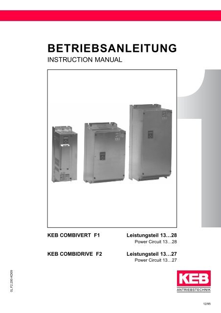
BETRIEBSANLEITUNG<br />
INSTRUCTION MANUAL<br />
KEB COMBIVERT F1 Leistungsteil 13…28<br />
Power Circuit 13…28<br />
KEB COMBIDRIVE F2 Leistungsteil 13…27<br />
Power Circuit 13…27<br />
ANTRIEBSTECHNIK<br />
12/95
Vor jeglichen Arbeiten muß sich der Anwender mit dem Gerät vertraut machen.<br />
Da<strong>ru</strong>nter fällt insbesondere die Kenntnis und Beachtung der Sicherheits- und<br />
Warnhinweise.<br />
Die in dieser Betriebsanleitung verwendeten Pictogramme entsprechen folgender<br />
Bedeutung:<br />
© KEB 0L.F2.200-KD09 12/95<br />
Gefahr<br />
Warnung<br />
Vorsicht<br />
Achtung<br />
Information<br />
Wird verwendet, wenn Leben oder Gesundheit des<br />
Benutzers gefährdet sind oder erheblicher Sachschaden<br />
auftreten kann.<br />
Unbedingt beachten! Besondere Hinweise<br />
für den sicheren und stö<strong>ru</strong>ngsfreien Betrieb.<br />
Hilfestellung, Tip
Diese Betriebsanleitung<br />
– ist gültig für KEB COMBIVERT F1–P Größe 14…28<br />
KEB COMBIVERT F1–K Größe 13…22<br />
KEB COMBIDRIVE F2 Größe 13…27<br />
– muß jedem Anwender zugänglich gemacht werden<br />
ANTRIEBSTECHNIK<br />
D 3<br />
D
D<br />
D 4<br />
Nur qualifiziertes<br />
Elektrofachpersonal<br />
Normen<br />
beachten<br />
Fehlerstrom-<br />
Schutzschalter<br />
Kondensatorentladezeit<br />
beachten<br />
Steuerleitungen<br />
Automatischer<br />
Wiederanlauf<br />
Spannungen<br />
gegen Erde<br />
Spannungsspitzen<br />
Isolationsmessungen<br />
Potentialunterschiede<br />
Betriebsanleitung<br />
lesen<br />
Sicherheitshinweise<br />
Der KEB COMBIVERT wird mit Spannungen betrieben, die bei Berüh<strong>ru</strong>ng einen<br />
lebensgefährlichen Schlag hervor<strong>ru</strong>fen können. Die Installation des Gerätes, sowie<br />
erhältliches Zubehör, ist deshalb nur durch qualifiziertes Elektrofachpersonal mit<br />
entsprechender Unterweisung zulässig.<br />
Stellen Sie sicher, daß die einschlägigen Normen zur Errichtung von elektrischen<br />
Anlagen VDE 0100, VDE 0160 (EN 50178), VDE 0113 (EN 60204) sowie die gültigen<br />
örtlichen Bestimmungen eingehalten werden.<br />
Ein Standard-Fehlerstromschutzschalter (puls-stromsensitiv) ist als alleinige<br />
Schutzmaßnahme bei Frequenzumrichterbetrieb nicht zulässig. (siehe<br />
Betriebsanleitung “Fehlerstromschutzschalter”)<br />
Nach dem Freischalten des Frequenzumrichters sind die Zwischenkreiskondensatoren<br />
noch kurzzeitig mit hoher Spannung geladen. Arbeiten am Gerät<br />
dürfen daher erst 5 Minuten nach dem Abschalten ausgeführt werden.<br />
Alle Steuerleitungen sind in weitere Schutzmaßnahmen (z.B. doppelt isoliert oder<br />
abgeschirmt, geerdet und isoliert) einzubeziehen, da es sich gemäß VDE 0100 um<br />
Spannungen handelt, die vom Versorgungskreis nicht sicher getrennt sind, weil<br />
Basisisolie<strong>ru</strong>ng verwendet wird.<br />
Der KEB COMBIVERT kann typenabhängig so eingestellt sein, daß er nach einem<br />
Spannungsausfall oder einem Unterspannungsfehler (UP) selbsttätig wieder anläuft.<br />
Für entsprechende Sicherheitsvorkeh<strong>ru</strong>ngen ist der Maschinenbauer verantwortlich.<br />
Allgemeine Hinweise zur Betriebssicherheit<br />
Der Anschluß der Umrichter ist nur an symmetrische Netze mit einer Spannung Phase<br />
(L1, L2, L3) gegen Nulleiter / Erde (N/PE) von max. 300V zulässig. Bei Versorgungsnetzen<br />
mit höheren Spannungen muß ein entsprechender Trenntransformator<br />
vorgeschaltet werden! Bei Nichtbeachtung kann der Umrichter zerstört werden.<br />
Beim Einsatz von IGBT-Umrichtern können Spannungsspitzen am Motor durch die<br />
Schaltvorgänge im Ausgang des FU entstehen, die das Isolationssystem des<br />
Motors gefährden. Dies ist besonders bei Motorleitungslängen größer 15m und<br />
beim Einsatz von Hochfrequenzmotoren zu beachten. Der Motor kann in diesem<br />
Fall mit Motordrosseln, du/dt-Filtern oder Sinusfiltern geschützt werden.<br />
Bei Durchfüh<strong>ru</strong>ng einer Isolationsmessung nach VDE 0100 / Teil 620 muß wegen<br />
Zerstö<strong>ru</strong>ngsgefahr der Leistungshalbleiter der KEB COMBIVERT abgeklemmt<br />
werden. Dies ist nach Norm zulässig, da alle Umrichter im Rahmen der Endkontrolle<br />
bei KEB einer Hochspannungsprüfung nach VDE 0160 (EN 50178) unterzogen werden.<br />
Bei Verwendung von Komponenten, die keine potentialgetrennten Ein-/Ausgänge<br />
verwenden ist es erforderlich, daß zwischen den zu verbindenen Komponenten<br />
Potentialgleichheit besteht (z.B. durch Ausgleichsleitung). Bei Mißachtung können<br />
die Komponenten durch Ausgleichströme zerstört werden.<br />
Bewahren Sie die Betriebsanleitung sorgfältig auf. Stellen Sie sicher, daß Sie von<br />
jedem Benutzer vollständig gelesen und konsequent beachtet wird. Dies gilt<br />
insbesondere für die darin aufgeführten Sicherheits-, Anschluß- und<br />
Betriebshinweise.
Inhaltsverzeichnis<br />
Inhaltsverzeichnis<br />
ANTRIEBSTECHNIK<br />
Einfüh<strong>ru</strong>ng .............................................................. D6<br />
KEB COMBIVERT / KEB COMBIDRIVE<br />
Verwendungszweck<br />
Sicherheitshinweise<br />
Auspacken<br />
Typenschlüssel<br />
Einbauhinweise ...................................................... D8<br />
Schaltschrankeinbau<br />
Verlustleistung<br />
Umweltbedingungen<br />
Gerätegröße 13…16 ............................................. D10<br />
Abmessungen<br />
Technische Daten<br />
Anschluß<br />
Beschreibung<br />
Gerätegröße 16…23 ............................................. D16<br />
Abmessungen<br />
Technische Daten<br />
Anschluß<br />
Beschreibung<br />
Gerätegröße 23…28 ............................................. D22<br />
Abmessungen<br />
Teschnische Daten<br />
Anschluß<br />
Betriebsbestimmungen ....................................... D26<br />
Anschlußhinweise<br />
Fehlerstromschutzschalter<br />
Störschutz<br />
Betriebshinweise<br />
Motorschutz<br />
Belastbarkeit des Motors<br />
Zubehör ................................................................. D30<br />
Bremswiderstand<br />
Netzdrossel<br />
Funkentstörfilter<br />
Kontrollmessungen.............................................. D36<br />
Gleichrichter<br />
Siche<strong>ru</strong>ngen<br />
Endstufe<br />
•<br />
D 5<br />
D
D<br />
Einfüh<strong>ru</strong>ng<br />
KEB COMBIVERT /<br />
KEB COMBIDRIVE<br />
Verwendungszweck<br />
Installations- und<br />
Sicherheitshinweise<br />
D 6<br />
qualifiziertes<br />
Elektrofachpersonal<br />
gefährliche<br />
spannungsführende<br />
Teile<br />
Mit dem KEB COMBIVERT / KEB COMBIDRIVE haben Sie einen Frequenzumrichter<br />
für hohe Ansprüche an Qualität und Dynamik erworben. Die in dieser<br />
Betriebsanleitung beschriebenen Leistungsteile werden wie folgt definiert:<br />
KEB COMBIVERT F1–P Frequenzumrichter mit hoher Motornennleistung,<br />
insbesondere für Pumpen- und Lüfterantriebe.<br />
Geräteg<strong>ru</strong>ppe F1-P ohne internem Bremstransistor!<br />
KEB COMBIVERT F1–K Standard Frequenzumrichter mit großen Überlastreserven<br />
( bis 200% I N ) und geräteinternem<br />
Bremstransistor.<br />
KEB COMBIDRIVE F2 Frequenzumrichter mit großen Überlastreserven<br />
(bis 200% I N ) und geräteinternem Bremstransistor<br />
(bis Größe 22). Der KEB COMBIDRIVE F2<br />
ist für den gesteuerten Betrieb, Drehzahl-/Stromregelung,<br />
Winkelsynchronregelung und als<br />
Einachspositioniersteue<strong>ru</strong>ng geeignet.<br />
Geräteg<strong>ru</strong>ppe Gerätegröße Bremsoption / Bremswiderstand<br />
F1-P 14…28 ❷ Anschluß einer externen Bremsoption<br />
F2 23…27 (Bremstransistor+Ansteue<strong>ru</strong>ng) und eines<br />
Bremswiderstandes möglich!<br />
Für Informationen über externe Bremsoption<br />
bitte Zusatzblatt anfordern!<br />
Art.Nr.: 20.F3.G70-K009<br />
Der KEB COMBIVERT/COMBIDRIVE dient ausschließlich zur stufenlosen<br />
Drehzahlverstellung von Drehstrommotoren. Er ist nicht zum Betreiben<br />
anderer elektrischer Verbraucher geeignet. Zuwiderhandlungen können zu<br />
Unfällen und Schäden führen, für die keine Haftung übernommen wird.<br />
Die Installation und Inbetriebnahme des KEB COMBIVERT/COMBIDRIVE,<br />
sowie erhältlichem Zubehör, ist nur durch qualifiziertes Elektrofachpersonal<br />
zulässig. Ein sicherer und stö<strong>ru</strong>ngsfreier Betrieb ist nur bei Einhaltung der jeweils<br />
gültigen Vorschriften gem. DIN VDE 0100, DIN VDE 0113, DIN VDE 0160, DIN<br />
VDE 0875 sowie einschlägiger örtlichen Bestimmungen gegeben.<br />
• Anschlußklemmen des Umrichters (Netzversorgung, Motoranschluß, Zwischenkreis)<br />
• Klemmen PA/PB (Bremswiderstand)<br />
• Anschlußklemmen des Motors<br />
Alle Anschluß- und Montagearbeiten nur im spannungslosen Zustand<br />
durchführen!
Auspacken<br />
• Bei äußerlichen Beschädigungen oder<br />
unvollständiger Liefe<strong>ru</strong>ng bitte Lieferant<br />
oder Spediteur informieren.<br />
• Originalverpackung nicht zerstören<br />
Typenschlüssel<br />
15. F1. P00 – 3449<br />
ANTRIEBSTECHNIK<br />
ANTRIEBSTECHNIK<br />
Standard V 1.3<br />
Schaltfrequenz 1 = 2 KHz<br />
2 = 4 KHz<br />
4 = 8 KHz<br />
8 = 16 KHz<br />
Anschlußspannung 4 = 400 V Klasse<br />
Anschlußphasen 3 = 3phasig<br />
Optionen 0 = Standard<br />
1 = digitale Option<br />
2 = analoge Option<br />
Einfüh<strong>ru</strong>ng<br />
ANTRIEBSTECHNIK<br />
für P-Leistungsteil 0 = Standard<br />
2 = Funkentstörfilter (bis Größe 23 intern)<br />
für K-Leistungsteil 1 = GTR7 (standard)<br />
3 = GTR7 + Funkentstörfilter (bis Größe 22 intern)<br />
Version Leistungsteil P (F1 P-Version Größe 14…28)<br />
R (F1 / F2 K-Version Größe 13…16)<br />
2 (F1 / F2 K-Version Größe 16…27)<br />
Typenbezeichnung F1 / F2<br />
Gerätegröße 13…28<br />
D 7<br />
D
D<br />
Einbauhinweise<br />
Schaltschrankeinbau<br />
D 8<br />
KEB<br />
COMBIVERT/<br />
COMBIDRIVE<br />
Schaltschrankoberfläche Berechnung der Schaltschrankoberfläche:<br />
A =<br />
PV [m2 ΔT • K<br />
]<br />
Eigenkühlung<br />
Kühllufteintritt<br />
Richtung der Kühlrippen<br />
A = Schaltschrankoberfläche [m 2 ]<br />
ΔT = Temperaturdifferenz [K]<br />
(Standardwert = 20 K)<br />
K = Wärmedurchgangszahl<br />
W<br />
(Standardwert = 5 m )<br />
2 • K<br />
Warmluftaustritt<br />
P V = Verlustleistung (siehe Tabelle Seite D9)<br />
V = Luftdurchsatz des Ventilators<br />
150<br />
KEB<br />
COMBIVERT /<br />
COMBIDRIVE<br />
100<br />
Luftdurchsatz mit Ventilatorkühlung:<br />
V =<br />
3,1 • PV [m3 ΔT<br />
/h]<br />
W<br />
[ ]<br />
m 2 • K<br />
Mindestabstände<br />
Nähere Angaben entnehmen Sie bitte den Katalogen der Schaltschrankhersteller.<br />
Gerätegröße 13…23 Bei einer Kühlkörpertemperatur von ca. 55 °C werden<br />
Innenraumlüfter und Kühlkörperlüfter des KEB COM-<br />
BIVERT/COMBIDRIVE selbsttätig eingeschaltet.<br />
Sinkt die Kühlkörpertemperatur anschließend unter<br />
50 °C, werden die Lüfter wieder ausgeschaltet.<br />
Gerätegröße 24…28 Unabhängig von der Kühlkörper- oder Umgebungstemperatur<br />
sind beide Lüfter ständig in Betrieb.
Verlustleistung<br />
Abhängigkeit von Verlustleistung<br />
und Schaltfrequenz<br />
PV16<br />
PV8<br />
PV4<br />
PV2<br />
Einbauhinweise<br />
2 kHz 4 kHz 8 kHz<br />
16 kHz<br />
ANTRIEBSTECHNIK<br />
Verlustleistung (P ) bei Nennlast<br />
V<br />
Größe P bei 2 kHz V P bei 4 kHz V P bei 8 kHz V P bei 16 kHz<br />
V<br />
13.F1/F2 170 W 210 W 280 W 420 W<br />
14.F1/F2 230 W 280 W 370 W 550 W<br />
15.F1/F2 350 W 430 W 570 W 850 W<br />
16.F1/F2 480 W 580 W 770 W 1150 W<br />
17.F1/F2 600 W 730 W 970 W 1450 W<br />
18.F1/F2 730 W 880 W 1170 W 1750 W<br />
19.F1/F2 880 W 1050 W 1400 W 2100 W<br />
20.F1/F2 1080 W 1300 W 1730 W –<br />
21.F1/F2 1300 W 1550 W 2070 W –<br />
22.F1/F2 1670 W 2000 W 2670 W –<br />
23.F1/F2 2190 W 2630 W – –<br />
24.F1/F2 2600 W 3130 W – –<br />
25.F1/F2 3020 W 3630 W – –<br />
26.F1/F2 3600 W 4330 W – –<br />
27.F1/F2 4330 W – – –<br />
28.F1 5330 W – – –<br />
Verlustleistung<br />
P V16 ♠ 2 • P V4<br />
Umweltbedingungen • Max. zulässige Grenzwerte<br />
– Kühlmitteleintritts-/Umgebungstemperatur im Betrieb:<br />
Geräteg<strong>ru</strong>ppe F1-K / F2: -10 °C…+45 °C<br />
Geräteg<strong>ru</strong>ppe F1-P : -10 °C…+40 °C<br />
– Lage<strong>ru</strong>ngstemperatur: -25 °C…+70 °C<br />
– Transporttemperatur: -25 °C…+70 °C<br />
Schaltfrequenz<br />
• Relative Luftfeuchtigkeit: max. 90 %, keine Betauung, Kennbuchstabe „F“ DIN 40040<br />
Es darf kein Nebel oder Wasser in den Frequenzumrichter eindringen.<br />
• Das Eindringen von Staub in den KEB COMBIVERT/COMBIDRIVE ist zu vermeiden.<br />
Bei Einbau in ein staubdichtes Gehäuse auf ausreichende Wärmeabfuhr achten.<br />
• Den KEB COMBIVERT/COMBIDRIVE gegen aggressive Gase und Flüssigkeiten<br />
schützen.<br />
• Bei Einbau in Ex-geschützten Räumen muß ein explosionsgeschütztes Gehäuse<br />
verwendet werden. Die geltenden Vorschriften sind zu beachten!<br />
Bei Aufstellhöhen über 1000 m bis max. 3000 m ist eine Leistungsreduzie<strong>ru</strong>ng von 1<br />
% pro 100 m zu berücksichtigen, d.h. 1500 m NN = 95 % P Nenn<br />
D 9<br />
D
D<br />
Abmessungen Größe 13…16<br />
Aufbauversion<br />
Durchsteckversion<br />
Geräte- Gewicht [kg]<br />
g<strong>ru</strong>ppe Größe A B C G H I J K L M N P R S ohne mit<br />
Funkentstörfilter<br />
F1-K / F2 13…16 200 570 355 140 270 9 45 43,5 475 545 393 170 110 83 21 27<br />
D 10<br />
max. 45<br />
Beim Einbau beachten!<br />
Steuerkarte<br />
Achtung !<br />
Attention !<br />
bis max. 445<br />
H<br />
I<br />
F1-P 14…16 200 570 355 140 270 9 45 43,5 475 545 393 170 110 83 21 27<br />
G<br />
A<br />
S<br />
Achtung !<br />
Attention !<br />
L<br />
M<br />
K<br />
J<br />
Steuerkabel<br />
I<br />
Schaltschrankausschnitt<br />
für Durchsteckversion<br />
N M B<br />
P<br />
G<br />
C<br />
R<br />
B
ANTRIEBSTECHNIK<br />
Technische Daten GRÖßE 13 14 15 16<br />
Belastbarkeit<br />
AUSGANG<br />
Nennleistung1) [kVA] 8,3 11,0 17,0 23,0<br />
Nennstrom [A] 12,0 16,5 24,0 33,0<br />
Max. zul. Motornennleistung[kW] 5,5 7,5 11,0 15,0<br />
Spannung [V] 3 x 0…UNetz Frequenz<br />
Max. Schaltfrequenz<br />
siehe Steuerkarte<br />
Geräteg<strong>ru</strong>ppe F1–K / F2 [kHz] 16 16 16 8<br />
Geräteg<strong>ru</strong>ppe F1-P [kHz] – 8 8 8<br />
NETZEINGANG<br />
Spannung [V] 305…500 ±0%<br />
Frequenz [Hz] 50/60 ± 2 Hz<br />
Phasen 3<br />
Schutzart IP20<br />
Max. zul. Netzsiche<strong>ru</strong>ng [A] 20 25 35 50<br />
Leitungsquerschnitt 2) [mm2 ] 2,5 4 6 10<br />
Zeit<br />
[sek.]<br />
300<br />
270<br />
240<br />
210<br />
180<br />
150<br />
120<br />
90<br />
60<br />
30<br />
Technische Daten Größe 13…16<br />
1) bezogen auf 400 V Nennspannung<br />
2) Empfohlener Mindestquerschnitt bei Nennleistung und Leitungslänge bis 100 m (Kupfer)<br />
Der KEB COMBIVERT/COMBIDRIVE muß so ausgelegt werden, daß die maximal zulässige<br />
Motornennleistung und der Umrichternennstrom nicht überschritten werden! Bei Spezial- oder<br />
Mittelfrequenzmotoren setzen Sie sich bitte mit KEB in Verbindung.<br />
1<br />
105 110 120 130 140 150 160 170 180 190 200<br />
LeistungsteilF1-K / F2 Größe 13…16<br />
LeistungsteilF1-P Größe 14…16<br />
max. Belastbarkeit abhängig<br />
1 von der Gerätegröße<br />
Auslastung [%]<br />
D 11<br />
D
D<br />
Anschluß Größe 13…16<br />
D 12<br />
Bremswiderstand feuerfest und<br />
berüh<strong>ru</strong>ngssicher einbauen!<br />
L1<br />
L2<br />
L3<br />
PE<br />
Für Frequenzumrichterbetrieb<br />
geeignete Schutzmaßnahmen<br />
verwenden!<br />
L1<br />
L2<br />
L3<br />
PE<br />
PA PB<br />
+<br />
Charge<br />
Steuerteil<br />
Option (nur für Geräteg<strong>ru</strong>ppe F1-K / F2)<br />
U<br />
V<br />
W<br />
PE<br />
Steuer- und Leistungsleitungen getrennt verlegen!<br />
Möglichst kurze verdrillte Leitungen verwenden!<br />
M<br />
3 ~<br />
Bei Funkstörschutzmaßnahmen<br />
den Schirm beidseitig auflegen!<br />
Bei niederfrequenten Stö<strong>ru</strong>ngen<br />
gem. VDE 0160 entstören!<br />
Standard-Fehlerstrom (FI)-Schutzschalter können nur bedingt in<br />
Verbindung mit Frequenzumrichtern eingesetzt werden.<br />
Nullung als Schutzmaßnahme ist am Umrichterausgang untersagt,<br />
siehe Betriebsbestimmungen Fehlerstrom-Schutzschalter!<br />
Der KEB COMBIVERT/COMBIDRIVE ist für einen festen Anschluß<br />
bestimmt, siehe Betriebsbestimmungen Anschlußhinweise!<br />
Maßnahmen zur Funkentstö<strong>ru</strong>ng und Störschutzmaßnahmen<br />
befinden sich unter Betriebsbestimmungen Störschutz!
Leistungsteil<br />
R<br />
PE L1 L2 L3 PE PA Ð PB PE U V W<br />
PE T 40 OH OH PE<br />
PE L L L<br />
1 2 3<br />
M<br />
3 ~<br />
LD1<br />
q<br />
Anschluß Größe 13…16<br />
LD1 Charge-LED zeigt Zwischenkreisladung an<br />
L1, L2, L3 Netzversorgung (3 Phasen)<br />
PA, PB Anschluß Bremswiderstand<br />
PA = Gleichspannungszwischenkreis +<br />
PB = Bremstransistor<br />
– Gleichspannungszwischenkreis –<br />
U, V, W Motor<br />
PE Schutzleiter<br />
T, R40 getrennte Versorgung Steuerkarte<br />
OH, OH externe Temperaturüberwachung (Anschluß und Funktion s.S. D28)<br />
Geräteg<strong>ru</strong>ppe Gerätegröße Anschlußklemmen<br />
L1 L2 L3<br />
M<br />
3 ~<br />
ANTRIEBSTECHNIK<br />
F1-P 14…16 ❷ Klemmen „PA“ und „PB“ entfallen; neu: Klemme „ + “ (Gleichspannungszwischenkreis<br />
+)<br />
Anschluß Standard<br />
Vor einem Eingriff<br />
das Gerät<br />
vom Netz trennen<br />
und ca. 5<br />
Minuten warten!<br />
Schirm großflächig am Motorgehäuse<br />
anschließen!<br />
Anschluß mit Funkentstörfilter (s.S. D35)<br />
R<br />
PE L1 L2 L3 PE PA Ð PB PE U V W<br />
PE T 40 OH OH PE<br />
PE<br />
PE L 1<br />
L<br />
2<br />
L<br />
3<br />
Vor einem Eingriff<br />
das Gerät<br />
vom Netz trennen<br />
und ca. 5<br />
Minuten warten!<br />
LD1<br />
Schirm beidseitig (Motorgehäuse,<br />
Verschraubung)<br />
großflächig anschließen!<br />
Funkentstörfilter<br />
nur für Schirmung nur für Schirmung<br />
q<br />
D 13<br />
D
D<br />
Getrennte Spannungsversorgung Größe 13…16<br />
Anschlußbedingungen<br />
Fehlermeldungen<br />
D 14<br />
Die Steuerkarte des KEB COMBIVERT/COMBIDRIVE arbeitet bei getrennter<br />
Spannungsversorgung unabhängig vom Leistungsteil. Die Anzeige der Statusund<br />
Fehlermeldungen sowie die Parametrie<strong>ru</strong>ng des Frequenzumrichters ist<br />
daher auch im spannungsfreien Zustand des Leistungsteils möglich.<br />
T3<br />
CN5A CN5B<br />
1<br />
CN8<br />
1<br />
A B<br />
S4<br />
F1<br />
Leiterplatte COMBIVERT/COMBIDRIVE Schaltnetzteil-Karte<br />
1<br />
Vor dem Anschluß der getrennten Spannungsversorgung sind flgd. Einstellungen<br />
auf der Schaltnetzteil-Karte (s. Abb.) durchzuführen.<br />
Einstellung bei<br />
Standardeinstellung getrennter Spannungsversorgung<br />
Steckverbinder CN6 (schwarz/rot) Steckplatz CN6 Steckplatz CN7<br />
Steckverbinder CN7 (schw./schw.) Steckplatz CN7 Steckplatz CN6<br />
Schalter S1 Position A Position A<br />
Schalter S2 Position A Position A<br />
Schalter S3 Position A Position A<br />
Der Anschluß der getrennten Spannungsversorgung, ca. 400 V ~, erfolgt an den<br />
Klemmen T, R40 (s.S. D13).<br />
Maximale Stromaufnahme der Steuerkarte: 250 mA<br />
• wird angezeigt, wenn bei eingeschaltetem KEB COMBIVERT/COMBIDRIVE<br />
die Versorgungsspannung des Leistungsteils entfällt.<br />
• wird kurzzeitig (bis die LED-Anzeige erlischt) angezeigt, wenn ein gleichzeitiger<br />
Spannungsausfall von Leistungsteil und Steuerkarte erfolgt.<br />
• wird kurzzeitig (bis die LED-Anzeige erlischt) angezeigt, wenn bei eingeschaltetem<br />
KEB COMBIVERT/COMBIDRIVE die Versorgungsspannung der<br />
Steuerkarte entfällt.<br />
• wird angezeigt, wenn bei ausgeschaltetem KEB COMBIVERT/COMBIDRIVE<br />
die Versorgungsspannung der Steuerkarte eingeschaltet wird.<br />
Um ein Wiederanlaufen des Frequenzumrichters sicherzustellen, die Funktionen<br />
„Automatik Reset UP“ und „Drehzahlsuche“ aktivieren (siehe Betriebsanleitung<br />
Teil 2 „Steuerteil“).<br />
CN11<br />
cn20<br />
CN6<br />
1<br />
CN4<br />
NET1<br />
1<br />
CN7<br />
NET2<br />
1<br />
20<br />
1<br />
CN10<br />
RH2<br />
LD1<br />
AA<br />
A S3 S2<br />
S1 BB<br />
B<br />
XX.F2.088-0019
Funktionsbedingungen<br />
1<br />
Netz-Aus-Funktion Größe 13…16<br />
ANTRIEBSTECHNIK<br />
Die Netz-Aus-Funktion hat die Aufgabe, bei Unterspannung (z.B. aufg<strong>ru</strong>nd eines<br />
Netzausfalls) für eine geführte Verzöge<strong>ru</strong>ng des Antriebs bis zum Stillstand zu<br />
sorgen.<br />
Nur bei KEB COMBIVERT F1 möglich! Bevor eine Ände<strong>ru</strong>ng im Leistungsteil<br />
erfolgt, muß die Netz-Aus-Funktion anhand der Steuerkarte aktiviert werden<br />
(siehe Betriebsanleitung Teil 2 „Steuerteil“).<br />
T3<br />
CN5A CN5B<br />
1<br />
CN8<br />
1<br />
A B<br />
S4<br />
Leiterplatte COMBIVERT Schaltnetzteil-Karte<br />
F1<br />
Zur Nutzung der Netz-Aus-Funktion sind flgd. Einstellungen auf der Schaltnetzteil-Karte<br />
(s. Abb.) durchzuführen.<br />
Standardeinstellung Einstellung für<br />
Netz-Aus-Funktion<br />
Steckverbinder CN6 (schwarz/rot) Steckplatz CN6 Steckplatz CN6<br />
Steckverbinder CN7 (schw./schw.) Steckplatz CN7 Steckplatz CN7<br />
Schalter S1 Position A Position B<br />
Schalter S2 Position A Position A<br />
Schalter S3 Position A Position B<br />
Parametereinstellungen der Netz-Aus-Funktion siehe Betriebsanleitung Teil 2<br />
„Steuerteil“!<br />
CN11<br />
cn20<br />
CN6<br />
1<br />
CN4<br />
NET1<br />
1<br />
CN7<br />
NET2<br />
1<br />
20<br />
1<br />
CN10<br />
RH2<br />
LD1<br />
A S3 S2<br />
S1 BB<br />
B<br />
AA<br />
XX.F2.088-0019<br />
D 15<br />
D
D<br />
Abmessungen Größe 16…23<br />
Aufbauversion<br />
Durchsteckversion<br />
D 16<br />
M<br />
I<br />
G<br />
A<br />
H S<br />
Geräte- Gewicht [kg]<br />
g<strong>ru</strong>ppe Größe A B B1 * C D E F G H I K M N P R S ohne mit<br />
Funkentstörfilter<br />
F1-K / F2 16…19 345 610 660 360 310 6 580 250 271 11 32,5 585 545 315 110 85,5 45 57<br />
20…22 345 800 876 360 310 6 770 250 271 11 32,5 775 735 315 110 85,5 65 80<br />
F1-P 17…20 345 610 660 360 310 6 580 250 271 11 32,5 585 545 315 110 85,5 45 57<br />
21…23 345 800 876 360 310 6 770 250 271 11 32,5 775 735 315 110 85,5 65 80<br />
* Maß mit Funkentstörfilter<br />
K<br />
N<br />
C<br />
Steuerkabel<br />
P<br />
D<br />
R<br />
Schaltschrankausschnitt<br />
für Durchsteckversion<br />
E<br />
B B1<br />
F B
Technische Daten<br />
Belastbarkeit<br />
ANTRIEBSTECHNIK<br />
GRÖßE 16 17 18 19 20 21 22 23<br />
AUSGANG<br />
Nennleistung 1) [kVA] 23 29 35 42 52 62 80 104<br />
Nennstrom [A] 33 42 50 60 75 90 115 150<br />
Max. zul. Motornennleistung[kW] 15 18,5 22 30 37 45 55 75<br />
Spannung [V] 3 x 0…UNetz Frequenz<br />
Max. Schaltfrequenz<br />
siehe Steuerkarte<br />
Geräteg<strong>ru</strong>ppe F1–K / F2[kHz] 16 16 16 16 8 8 8 –<br />
Geräteg<strong>ru</strong>ppe F1-P [kHz] – 8 8 8 8 8 8 4<br />
NETZEINGANG<br />
Technische Daten Größe 16…23<br />
Spannung [V] 305…500 ±0%<br />
Frequenz [Hz] 50/60 ± 2 Hz<br />
Phasen 3<br />
Schutzart IP20<br />
Max. zul. Netzsiche<strong>ru</strong>ng [A] 50 63 80 80 100 125 1602) 200<br />
Leitungsquerschnitt 3) [mm2 ] 10 16 25 25 35 50 50 95/504) 1) bezogen auf 400 V Nennspannung<br />
2) Netzsiche<strong>ru</strong>ng Typ aM ( IEC 269 )<br />
3) Empfohlener Mindestquerschnitt bei Nennleistung und Leitungslänge bis 100 m (Kupfer)<br />
4) siehe Anschlußbild Seite D18<br />
Der KEB COMBIVERT/COMBIDRIVE muß so ausgelegt werden, daß die max. zulässige<br />
Motornennleistung und der Umrichternennstrom nicht überschritten werden! Bei Spezial- oder<br />
Mittelfrequenzmotoren setzen Sie sich bitte mit KEB in Verbindung.<br />
Zeit<br />
[sek.]<br />
300<br />
270<br />
240<br />
210<br />
180<br />
150<br />
120<br />
90<br />
60<br />
30<br />
1<br />
105 110 120 130 140 150 160 170 180 190 200<br />
LeistungsteilF1-K / F2 Größe 16…22<br />
LeistungsteilF1-P Größe 17…23<br />
max. Belastbarkeit abhängig<br />
1 von der Gerätegröße<br />
Auslastung [%]<br />
D 17<br />
D
D<br />
Anschluß Größe 16…23<br />
Anschluß Größe 16…22<br />
D 18<br />
L1<br />
L2<br />
L3<br />
PE<br />
U1<br />
V1<br />
W1<br />
L1<br />
L2<br />
L3<br />
PE<br />
Für Frequenzumrichterbetrieb geeignete<br />
Schutzmaßnahmen verwenden!<br />
Anschluß Größe 23<br />
Leitung:<br />
95 mm 2<br />
Netzdrossel<br />
Bremswiderstand feuerfest und berüh<strong>ru</strong>ngssicher einbauen!<br />
U2<br />
V2<br />
W2<br />
L1<br />
L2<br />
L3<br />
PE<br />
L1<br />
L2<br />
L3<br />
PE<br />
PA PB<br />
+<br />
Charge<br />
Steuerteil<br />
+ Ð<br />
+<br />
Charge<br />
U<br />
V<br />
W<br />
PE<br />
Steuer- und Leistungsleitungen getrennt verlegen!<br />
Gerätegröße 23 nur mit Netzdrossel betreiben!<br />
Leitung:<br />
50 mm 2 /<br />
max. 3 m<br />
Steuerteil<br />
Option (nur für Geräteg<strong>ru</strong>ppe F1-K / F2)<br />
Möglichst kurze verdrillte<br />
Leitungen verwenden!<br />
U<br />
V<br />
W<br />
PE<br />
Steuer- und Leistungsleitungen getrennt verlegen!<br />
Der KEB COMBIVERT/COMBIDRIVE ist für einen festen Anschluß<br />
bestimmt, siehe Betriebsbestimmungen Anschlußhinweise!<br />
Maßnahmen zur Funkentstö<strong>ru</strong>ng und Störschutzmaßnahmen<br />
befinden sich unter Betriebsbestimmungen Störschutz!<br />
M<br />
3~<br />
Bei Funkstörschutzmaßnahmen<br />
den Schirm beidseitig auflegen!<br />
Bei niederfrequenten Stö<strong>ru</strong>ngen<br />
gem. VDE 0160 entstören!<br />
M<br />
3~<br />
Standard-Fehlerstrom (FI)-Schutzschalter können nur bedingt in<br />
Verbindung mit Frequenzumrichtern eingesetzt werden.<br />
Nullung als Schutzmaßnahme ist am Umrichterausgang untersagt,<br />
siehe Betriebsbestimmungen Fehlerstrom-Schutzschalter!<br />
Bei Funkstörschutzmaßnahmen<br />
den Schirm beidseitig auflegen!<br />
Bei niederfrequenten Stö<strong>ru</strong>ngen<br />
gem. VDE 0160 entstören!
Anschluß Größe 16…23<br />
Leistungsteil LD1 Charge-LED zeigt Zwischenkreisladung an<br />
L1, L2, L3 Netzversorgung (3 Phasen)<br />
PA, PB Bremswiderstand<br />
PA = Gleichspannungszwischenkreis +<br />
PB = Bremstransistor<br />
– Gleichspannungszwischenkreis –<br />
U, V, W Motor<br />
PE Schutzleiter<br />
T, R40 getrennte Versorgung Steuerkarte<br />
OH, OH externe Temperaturüberwachung (Anschluß und Funktion s.S. D28)<br />
LD1<br />
Geräteg<strong>ru</strong>ppe Gerätegröße Anschlußklemmen<br />
Anschluß Standard<br />
Schirm großflächig am<br />
Motorgehäuse anschließen!<br />
LD1<br />
ANTRIEBSTECHNIK<br />
F1-P 16…23 ❷ Klemmen „PA“ und „PB“ entfallen; neu: Klemme „ + “ (Gleichspannungszwischenkreis<br />
+)<br />
Vor einem Eingriff das<br />
Gerät vom Netz trennen<br />
und ca.5 Min. warten!<br />
R<br />
PE L1 L2 L3 PE PA Ð PB PE U V W<br />
PE T 40 OH OH PE<br />
PE L L L<br />
1 2 3<br />
M<br />
3 ~<br />
R<br />
PE L1 L2 L3 PE PA Ð PB PE U V W<br />
PE T 40 OH OH PE<br />
PE L L L<br />
1 2 3<br />
Anschluß mit Funkentstörfilter (s.S. D35)<br />
Vor einem Eingriff das<br />
Gerät vom Netz trennen<br />
und ca.5 Min. warten!<br />
nur für Schirmung nur für Schirmung<br />
q<br />
M<br />
3 ~<br />
Schirm beidseitig<br />
(Motorgehäuse, Verschraubung)<br />
großflächig anschließen!<br />
Gerätegröße 23 nur mit Netzdrossel betreiben! (siehe Anschlußbild Seite D18)<br />
q<br />
Funkentstörfilter<br />
D 19<br />
D
D<br />
Getrennte Spannungsversorgung Größe 16…23<br />
Anschlußbedingungen<br />
Fehlermeldungen<br />
D 20<br />
Die Steuerkarte des KEB COMBIVERT/COMBIDRIVE arbeitet bei getrennter<br />
Spannungsversorgung unabhängig vom Leistungsteil. Die Anzeige der Statusund<br />
Fehlermeldungen sowie die Parametrie<strong>ru</strong>ng des Frequenzumrichters ist daher<br />
auch im spannungsfreien Zustand des Leistungsteils möglich.<br />
CN1 CN2 CN3<br />
LD1<br />
+<br />
C74<br />
+<br />
C75<br />
NET6<br />
NET1<br />
CN21 CN22<br />
B A<br />
S2<br />
B A<br />
B A S3<br />
S1<br />
CN7<br />
NET7<br />
T1<br />
K1<br />
NET3<br />
NET8<br />
NET4<br />
NET5<br />
CN5 CN6<br />
Vor dem Anschluß der getrennten Spannungsversorgung sind flgd. Einstellungen<br />
auf der Treiberplatine (s.Abb.) durchzuführen:<br />
Einstellung bei getrennter<br />
Standardeinstellung Spannungsversorgung<br />
Steckverbinder CN21 (violett/violett) Steckplatz CN21 Steckplatz CN22<br />
Steckverbinder CN22 (rot/blau) Steckplatz CN22 Steckplatz CN21<br />
Schalter S1 Position A Position A<br />
Schalter S2 Position A Position A<br />
Schalter S3 Position A Position A<br />
Der Anschluß der getrennten Spannungsversorgung, ca. 400 V ~, erfolgt an den<br />
Klemmen T, R40 (s.S. D19).<br />
Maximale Stromaufnahme der Steuerkarte: 250 mA<br />
• wird angezeigt, wenn bei eingeschaltetem KEB COMBIVERT/COMBIDRIVE die<br />
Versorgungsspannung des Leistungsteils entfällt.<br />
• wird kurzzeitig (bis die LED-Anzeige erlischt) angezeigt , wenn ein gleichzeitiger<br />
Spannungsausfall von Leistungsteil und Steuerkarte erfolgt.<br />
• wird kurzzeitig (bis die LED-Anzeige erlischt) angezeigt, wenn bei eingeschaltetem<br />
KEB COMBIVERT/COMBIDRIVE die Versorgungsspannung der Steuerkarte<br />
entfällt.<br />
• wird angezeigt, wenn bei ausgeschaltetem KEB COMBIVERT/COMBIDRIVE die<br />
Versorgungsspannung der Steuerkarte eingeschaltet wird.<br />
Um ein Wiederanlaufen des Frequenzumrichters sicherzustellen, die Funktionen<br />
„Automatik Reset UP“ und „Drehzahlsuche“ aktivieren (s. Betriebsanleitung Teil 2<br />
„Steuerteil“).<br />
CN10<br />
CN14 CN15 CN16 CN17 CN18 CN19 CN20<br />
XX.F2.081-0009<br />
F1 T6 T7<br />
CN<br />
4<br />
Leiterplatte COMBIVERT/COMBIDRIVE Treiberplatine<br />
NET9<br />
UT1<br />
NET10<br />
NET11<br />
NET12<br />
CN11<br />
CN CN<br />
13 12<br />
B A<br />
S4
Funktionsbedingungen<br />
CN1 CN2 CN3<br />
LD1<br />
+<br />
C74<br />
+<br />
C75<br />
NET6<br />
CN21 CN22<br />
Netz-Aus-Funktion Größe 16…23<br />
NET1<br />
B A<br />
S2<br />
B A<br />
B A S3<br />
S1<br />
CN7<br />
NET7<br />
T1<br />
K1<br />
NET3<br />
NET8<br />
NET4<br />
NET5<br />
CN5 CN6<br />
CN10<br />
CN14 CN15 CN16 CN17 CN18 CN19 CN20<br />
XX.F2.081-0009<br />
F1 T6 T7<br />
NET9<br />
UT1<br />
NET10<br />
NET11<br />
NET12<br />
ANTRIEBSTECHNIK<br />
Die Netz-Aus-Funktion hat die Aufgabe, bei Unterspannung (z.B. aufg<strong>ru</strong>nd eines<br />
Netzausfalls) für eine geführte Verzöge<strong>ru</strong>ng des Antriebs bis zum Stillstand zu<br />
sorgen.<br />
Nur bei KEB COMBIVERT F1 möglich! Bevor eine Ände<strong>ru</strong>ng im Leistungsteil erfolgt,<br />
muß die Netz-Aus-Funktion anhand der Steuerkarte aktiviert werden (s. Betriebsanleitung<br />
Teil 2 „Steuerteil“).<br />
CN<br />
4<br />
Leiterplatte COMBIVERT Treiberplatine<br />
CN11<br />
CN CN<br />
13 12<br />
B A<br />
S4<br />
Zur Nutzung der Netz-Aus-Funktion sind flgd. Einstellungen auf der Treiberplatine<br />
(s.Abb.) durchzuführen:<br />
Standardeinstellung Einstellung für<br />
Netz-Aus-Funktion<br />
Steckverbinder CN21 (violett/violett) Steckplatz CN21 Steckplatz CN21<br />
Steckverbinder CN22 (rot/blau) Steckplatz CN22 Steckplatz CN22<br />
Schalter S1 Position A Position B<br />
Schalter S2 Position A Position A<br />
Schalter S3 Position A Position B<br />
Parametereinstellungen der Netz-Aus-Funktion siehe Betriebsanleitung Teil 2<br />
„Steuerteil“!<br />
D 21<br />
D
D<br />
Abmessungen Größe 23…28<br />
Abmessungen<br />
D 22<br />
A<br />
Befestigungsmaße<br />
Befestigungs-<br />
Geräteg<strong>ru</strong>ppe Größe A B C D E schrauben Gewicht [kg]<br />
F2 23 412 616 377 380 576 M8 60<br />
24…25 510 824 356 462 782 M8 105<br />
26…27 510 824 408 462 782 M8 110<br />
F1-P 24 412 616 377 380 576 M8 60<br />
25…26 510 824 356 462 782 M8 105<br />
27…28 510 824 408 462 782 M8 110<br />
B<br />
D<br />
E<br />
C
Technische Daten<br />
Belastbarkeit<br />
ANTRIEBSTECHNIK<br />
GRÖßE 23 24 25 26 27 28<br />
AUSGANG<br />
Nennleistung 1) [kVA] 104 125 145 173 208 256<br />
Nennstrom [A] 150 180 210 250 300 370<br />
Max. zul. Motornennleistung[kW] 75 90 110 132 160 200<br />
Spannung [V] 3 x 0…UNetz Frequenz<br />
Max. Schaltfrequenz<br />
siehe Steuerkarte<br />
Geräteg<strong>ru</strong>ppe F2 [kHz] 4 4 4 4 2 –<br />
Geräteg<strong>ru</strong>ppe F1-P [kHz] – 4 4 4 2 2<br />
NETZEINGANG<br />
Technische Daten Größe 23…28<br />
Spannung [V] 305…500 ±0%<br />
Frequenz [Hz] 50/60 ± 2 Hz<br />
Phasen 3<br />
Schutzart IP20<br />
Max. zul. Netzsiche<strong>ru</strong>ng [A] 200 315 315 400 450 550<br />
Leitungsquerschnitt 2) [mm2 ] 95 95 95 120 150 185<br />
1) bezogen auf 400 V Nennspannung<br />
2) Empfohlener Mindestquerschnitt bei Nennleistung und Leitungslänge bis 100 m (Kupfer)<br />
Der KEB COMBIVERT/COMBIDRIVE muß so ausgelegt werden, daß die max. zulässige<br />
Motornennleistung und der Umrichternennstrom nicht überschritten werden! Bei Spezial- oder<br />
Mittelfrequenzmotoren setzen Sie sich bitte mit KEB in Verbindung.<br />
Zeit<br />
[sek.]<br />
300<br />
270<br />
240<br />
210<br />
180<br />
150<br />
120<br />
90<br />
60<br />
30<br />
1<br />
105 110 120 130 140 150 160 170 180 190 200<br />
LeistungsteilF2 Größe 23…27<br />
LeistungsteilF1-P Größe 24…28<br />
max. Belastbarkeit abhängig<br />
1 von der Gerätegröße<br />
Auslastung [%]<br />
D 23<br />
D
D<br />
Anschluß Größe 23…28<br />
Hinweise zur<br />
Hardware<br />
L1<br />
L2<br />
L3<br />
PE<br />
D 24<br />
U1<br />
V1<br />
W1<br />
U2<br />
V2<br />
W2<br />
U1<br />
V1<br />
W1<br />
PE<br />
Netzdrossel Funkentstörfilter<br />
– Gerätegrößen 23…28 nur mit Netzdrossel betreiben (s. Zubehör Netzdrossel)!<br />
– Netz-Aus-Funktion und getrennte Spannungsversorgung von Steuerteil und<br />
Leistungsteil nicht möglich!<br />
Gerätegröße 23…28 ohne internen Bremstransistor!<br />
Anschluß einer externen Bremsoption (Bremstransistor+Ansteue<strong>ru</strong>ng) und eines<br />
Bremswiderstandes möglich! Für Informationen über externe Bremsoption bitte<br />
Zusatzblatt Art.Nr.: 20.F3.G70-K009 anfordern!<br />
U2<br />
V2<br />
W2<br />
L1<br />
L2<br />
L3<br />
PE<br />
ZK+ ZKÐ<br />
+<br />
Steuerteil<br />
Steuer- und Leistungsleitungen<br />
getrennt verlegen!<br />
U<br />
V<br />
W<br />
PE<br />
Standard-Fehlerstrom (FI)-Schutzschalter können nur bedingt in<br />
Verbindung mit Frequenzumrichtern eingesetzt werden.<br />
Nullung als Schutzmaßnahme ist am Umrichterausgang untersagt,<br />
siehe Betriebsbestimmungen Fehlerstrom-Schutzschalter!<br />
Der KEB COMBIVERT/COMBIDRIVE ist für einen festen Anschluß<br />
bestimmt, siehe Betriebsbestimmungen Anschlußhinweise!<br />
Maßnahmen zur Funkentstö<strong>ru</strong>ng und Störschutzmaßnahmen<br />
befinden sich unter Betriebsbestimmungen Störschutz!<br />
M<br />
3 ~<br />
Bei Funkstörschutzmaßnahmen<br />
den<br />
Schirm beidseitig auflegen!<br />
Bei niederfrequenten<br />
Stö<strong>ru</strong>ngen<br />
gem. VDE 0160<br />
entstören!
ZKÐ<br />
ZK+<br />
U V W<br />
L1 L2 L3<br />
Anschluß Größe 23…28<br />
Leistungsteil L1, L2, L3 Netzversorgung (3 Phasen)<br />
ZK+,ZK- Gleichspannungszwischenkreis<br />
Anschluß externe Bremsoption<br />
ZKÐ<br />
ANTRIEBSTECHNIK<br />
U, V, W Motor<br />
PE Schutzleiter<br />
OH, OH externe Temperaturüberwachung (Anschluß und Funktion s.S. D28)<br />
X901, X902 ! Netzspannungspotential !<br />
nicht belegen – Klemmen reserviert für optionale Anwendung<br />
nur für Schirmung<br />
Vor einem Eingriff das Gerät<br />
vom Netz trennen und ca.5 Min.<br />
warten!<br />
nur für Schirmung<br />
PE PE<br />
OH<br />
OH<br />
X 902<br />
X 901<br />
ZKÐ<br />
ZK+<br />
L1 L2 L3 PE<br />
L1 L2 L3 PE<br />
U V W<br />
M<br />
3 ~<br />
PE<br />
Schirm großflächig<br />
am Motorgehäuse<br />
anschließen!<br />
PE PE<br />
OH<br />
OH<br />
X 902<br />
X 901<br />
ZKÐ<br />
ZK+<br />
Vor einem Eingriff das Gerät vom Netz<br />
trennen und ca.5 Min. warten!<br />
L1 L2 L3 PE<br />
L1 L2 L3 PE<br />
ZK+<br />
U V W PE<br />
L1 L2 L3 PE<br />
U V W PE<br />
M<br />
3 ~<br />
Schirm großflächig<br />
am Motorgehäuse<br />
anschließen!<br />
D 25<br />
D
D<br />
Betriebsbestimmungen<br />
Anschlußhinweise<br />
Fehlerstrom-<br />
Schutzschalter (FI)<br />
D 26<br />
Ein stö<strong>ru</strong>ngsfreier und sicherer Betrieb des Frequenzumrichters ist nur unter Beachtung der unten<br />
aufgeführten Anschlußhinweise gewährleistet:<br />
Bei Abweichungen von diesen Vorgaben können im Einzelfall Fehlfunktionen und Schäden<br />
auftreten.<br />
– Einbau und Anschluß nur durch ausgebildetes Personal.<br />
– Allgemeine Installationsvorschriften für das Errichten und Betreiben elektrischer Betriebsanlagen<br />
beachten (VDE 0100 / VDE 0160).<br />
– Schutzmaßnahmen für Mensch und Maschine sind entsprechend den örtlichen Gegebenheiten<br />
und Vorschriften durchzuführen.<br />
– Der KEB COMBIVERT/COMBIDRIVE ist für einen festen Anschluß bestimmt.<br />
– Keine Messungen am Gerät während des Betriebes durchführen.<br />
– Netz- und Motorleitungen nicht vertauschen.<br />
– Netzspannung und Motornennspannung beachten.<br />
– Steuer- und Leistungsleitungen getrennt verlegen!<br />
– Anschluß der Steuerleitungen nur an Schalt- und Einstellelemente (Relais, Schalter, Potentiometer),<br />
die für Kleinspannungen geeignet sind.<br />
– Abgeschirmte/verdrillte Steuerleitungen verwenden. Schirm auf PE auflegen!<br />
– Abgeschirmte Motorleitungen verwenden. Schirm auf PE bzw. großflächig am Motorgehäuse<br />
auflegen.<br />
– Frequenzumrichter gut erden : sternförmig; Erdschleifen vermeiden; kürzeste Verbindung zur<br />
Haupterde. Schutzleiterquerschnitt mindestens 10mm 2 Cu oder Verlegung eines zweiten Leiters<br />
elektrisch parallel zum Schutzleiter über getrennte Klemmen (VDE 0160).<br />
– Anschluß von Bremsoption / Bremswiderstand mit verdrillten Leitungen durchführen.<br />
Alle Leitungen sind in eine weitere Schutzmaßnahme einzubeziehen, da es<br />
sich nach VDE 0160 um keine berührbaren Spannungen handelt.<br />
1.Einsatz von pulsstromsensitiven Fehlerstrom-Schutzschaltern<br />
Standard (pulsstromsensitive) Fehlerstrom-Schutzschalter können nur<br />
bedingt in Verbindung mit Frequenzumrichtern eingesetzt werden.<br />
– Bei Frequenzumrichtern mit 3phasiger Eingangsspannung kann bei Erdschluß ein Gleichanteil im<br />
Fehlerstrom die Auslösung eines Standard-FI-Schutzschalters verhindern. Gemäß VDE 0160 ist<br />
deshalb eine FI-Schutzschaltung mit einem Standard-FI-Schutzschalter als alleinige Schutzmaßnahme<br />
nicht zulässig. In Abhängigkeit der vorhandenen Netzformen (TN, IT, TT) sind weitere<br />
Schutzmaßnahmen gemäß VDE 0100 Teil 410 erforderlich. Z.B.: Schutz durch Überstromschutzeinrichtung<br />
(TN-Netz), Isolationsüberwachung mit Pulscode-Meßverfahren (IT-Netz).<br />
Bei allen Netzformen kann Schutztrennung verwendet werden, sofern die erforderliche Leistung<br />
und Leitungslänge dies zulassen.<br />
– Der Standard-FI-Schutzschalter muß der neuen Bauweise gemäß DIN VDE 0664 entsprechen.<br />
– Der Auslösestrom sollte 300 mA oder mehr betragen, um vorzeitiges Auslösen durch Ableitströme<br />
des Umrichters zu vermeiden.<br />
– Richtwert der Ableitströme des KEB COMBIVERT/COMBIDRIVE ca. 200 mA.<br />
Abhängig von der Belastung, der Länge der Motorleitung und dem Einsatz eines Funkentstörfilters<br />
ist eine erhebliche Vergröße<strong>ru</strong>ng der Ableitströme möglich.<br />
2.Einsatz von allstromsensitiven Fehlerstrom-Schutzschaltern<br />
Der Einsatz von allstromsensitiven Fehlerstrom-Schutzschaltern erfordert auch bei Frequenzumrichtern<br />
mit 3phasiger Eingangsspannung keine weiteren Schutzmaßnahmen. Es sind lediglich die<br />
Anschlußhinweise des Herstellers zu beachten.<br />
3.Ausnahme<br />
Bei Frequenzumrichtern mit 1phasiger Eingangsspannung (L, N) ist ein alleiniger Schutz durch<br />
Standard-FI-Schutzschalter zulässig, wenn dieser der neuen Bauweise gemäß DIN VDE 0664<br />
entspricht.
Betriebsbestimmungen<br />
ANTRIEBSTECHNIK<br />
Störschutz des Steuer- und Leistungseingänge des Frequenzumrichters sind gegen Störeinflüsse geschützt.<br />
Frequenzumrichters<br />
Eine höhere Betriebssicherheit des Gerätes und zusätzlicher Schutz vor<br />
Funktionsstö<strong>ru</strong>ngen wird durch folgende Maßnahmen erreicht.<br />
Störschutz<br />
elektrischer<br />
Anlagen<br />
Betriebshinweise<br />
– Einsatz von Netzdrosseln, wenn die Netzspannung durch das Zuschalten großer Verbraucher (Kompensationsanlagen,<br />
Schweißgeräte, HF-Öfen, elektromagn. Aufspannfutter usw.) beeinflußt wird.<br />
– Schutzbeschaltung von induktiven Verbrauchern (Magnetventile, Schütze, Elektromagnete) durch<br />
RC-Glied o.ä., um die durch das Abschalten freiwerdenden Energien zu absorbieren.<br />
Paarige Verdrillung schützt gegen induktiv eingekoppelte Störspannungen. Abschirmung schützt<br />
gegen kapazitiv eingekoppelte Störspannungen. Verdrillte und abgeschirmte Leitungen ergeben bei<br />
getrennter Verlegung von Signal- und Leistungsleitungen einen optimalen Schutz.<br />
Der Frequenzumrichter KEB COMBIVERT/COMBIDRIVE sendet elektromagnetische Wellen hoher<br />
Frequenz aus. Entstehende Störimpulse, die evtl. elektrische Anlagen in der Umgebung stören,<br />
können durch folgende Maßnahmen verringert werden:<br />
– Einbau des Frequenzumrichters in ein Metallgehäuse<br />
– abgeschirmte Motorleitungen: Der Schirm muß am Frequenzumrichter an PE und am Motor an<br />
das Gehäuse angeschlossen werden (großflächig auflegen). Die Abschirmung darf nicht als Schutzerdung<br />
benutzt werden. Die sichere Funktion der Abschirmung ist nur dann gegeben, wenn sie nicht<br />
unterbrochen ist und möglichst nahe am Frequenzumrichter bzw. Motor beginnt.<br />
– gute Erdung, mindestens 10 mm 2 Erdleitung oder zusätzliches Masseband<br />
– Einsatz von Funkentstörfiltern<br />
– Leistungstrennschalter zwischen Spannungsversorgung und Frequenzumrichter installieren, damit<br />
eine unabhängige Abschaltung des KEB COMBIVERT/COMBIDRIVE möglich ist.<br />
– Bei Einzelantrieben ist das Schalten zwischen Motor und KEB COMBIVERT/COMBIDRIVE während<br />
des Betriebes zu vermeiden, da es zum Ansprechen der Schutzeinrichtungen des Frequenzumrichters<br />
führen kann. Ist das Schalten nicht zu vermeiden, sind Schutzmaßnahmen mit KEB abzustimmen.<br />
Bei Mehrmotorenantrieben ist das Zu- und Abschalten zulässig, wenn mindestens 1 Motor<br />
während des Schaltvorganges läuft. Der Frequenzumrichter ist auf die aufretenden Anlaufströme zu<br />
dimensionieren.<br />
– Wenn der Motor bei einem Neustart (Netz ein) des KEB COMBIVERT/COMBIDRIVE noch läuft (z.B.<br />
durch große Schwungmassen), muß die Funktion Drehzahlsuche oder DC-Bremsung aktiviert sein.<br />
– Wenn zwischen Motor und Frequenzumrichter geschaltet wird, muß die Funktion Drehzahlsuche<br />
aktiviert sein. Erst nach dem Schließen des Motorschützes darf die Funktion eingeleitet werden.<br />
– Häufiges, kurz aufeinanderfolgendes Schalten zwischen Netz und Frequenzumrichter ist nicht<br />
zulässig: zwischen Aus- und Wiedereinschalten ca. 60 s warten.<br />
Um eine frühzeitige Alte<strong>ru</strong>ng bzw. Zerstö<strong>ru</strong>ng des KEB COMBIVERT/<br />
COMBIDRIVE zu vermeiden, beachten Sie die vorstehenden HInweise.<br />
Der KEB COMBIVERT/COMBIDRIVE ist bedingt kurzschlußfest (VDE 0160).<br />
Nach dem Wiedereinschalten der Schutzeinrichtungen ist die bestimmungsgemäße<br />
Funktion gewährleistet.<br />
Ausnahmen:<br />
❿ Treten am Ausgang des KEB COMBIVERT/COMBIDRIVE wiederholt Erdschlüsse oder Kurzschlüsse<br />
auf, kann dies zu einem Defekt am Gerät führen.<br />
❡ Tritt ein Kurzschluß während des generatorischen Betriebes (2. bzw. 4. Quadrant, Rückspeisung in<br />
den Zwischenkreis) auf, kann dies zu einem Defekt am Gerät führen.<br />
D 27<br />
D
D<br />
Betriebsbestimmungen<br />
Motorschutz<br />
Funktionsbeschreibung<br />
D 28<br />
Motorschutzschalter bzw. Motorschutzrelais bieten bei Umrichterbetrieb nur<br />
bedingten Schutz und können im Einzelfall Fehlauslösungen hervor<strong>ru</strong>fen. Einen<br />
umfassenden Schutz gegen Überbeansp<strong>ru</strong>chung eines Motors im Umrichterbetrieb<br />
bietet eine PTC-Auswertung bzw. ein Thermistor-Motorschutz. Eine dafür<br />
erforderliche Auswertelektronik ist im KEB COMBIVERT/COMBIDRIVE serienmäßig<br />
integriert.<br />
Vor dem Anschluß eines Kaltleiters oder Thermokontaktes muß die Drahtbrücke<br />
an den Klemmen OH/OH entfernt werden.<br />
Thermistor-Motorschutz mit Kaltleiter (PTC):<br />
Anschluß von 1…3 PTC-Fühler (Reihenschaltung)<br />
Kaltwiderstand (ϑ = 25 °C / U - 2,5 V) - 100 ý<br />
max. Kaltwiderstand der PTC-Fühlerkette<br />
Fehlerauslösebereich<br />
Fehlerrücksetzbereich<br />
400 ý<br />
• 1500 ý (= ^ 4,7 V)<br />
- 460 ý (= ^ 2,5 V)<br />
Meßspannung < 2,5 V<br />
Klemme OH/OH offen 8 V<br />
Thermistor-Motorschutz mit Thermokontakt:<br />
Als weitere Möglichkeit können die Klemmen OH/OH<br />
mit einem Thermokontakt (Kontaktart Öffner) belegt<br />
werden.<br />
OH OH PE<br />
q<br />
OH OH PE<br />
Erreicht der Widerstandswert des PTC-Fühlers den Fehlerauslösebereich oder<br />
öffnet der Thermokontakt, schaltet der Frequenzumrichter den Ausgang UVW mit<br />
der Fehlermeldung E.OH ab.<br />
Kühlt sich der Motor soweit ab, daß der Widerstandswert des PTC-Fühlers<br />
- 460 ý ist oder der Thermokontakt wieder schließt, kann der Fehler durch<br />
Betätigen des Resets oder durch Power-on-Reset zurückgesetzt werden.
Belastbarkeit des Motors<br />
P<br />
PN<br />
M<br />
MN<br />
1,6<br />
1,4<br />
1,2<br />
1,0<br />
0,8<br />
0,6<br />
0,4<br />
0,2<br />
a<br />
b<br />
Betriebsbestimmungen<br />
10 20 30 40 50 60 70 80 90 100 f [Hz]<br />
c<br />
1<br />
d<br />
M K<br />
Bedingung: > 1,3<br />
M<br />
MKN > 3<br />
MN<br />
MKN > 2<br />
MN<br />
MKN > 3<br />
MN<br />
MKN > 2<br />
MN<br />
300 600 900 1200 1500 1800 2100 2400 2700 3000 n(1/min)<br />
P Leistung<br />
P Nennleistung<br />
N<br />
n Drehzahl<br />
M zulässiges Drehmoment<br />
M Motorkippmoment<br />
K<br />
M Motornennmoment<br />
N<br />
Motornennkippmoment<br />
M KN<br />
Kennlinie 1<br />
Kennlinie a<br />
Kennlinie b<br />
Kennlinie c<br />
Kennlinie d<br />
ANTRIEBSTECHNIK<br />
Überlastbereich<br />
Motortypabhängig<br />
Dimensionie<strong>ru</strong>ng<br />
des Motors für<br />
f > 50 Hz<br />
Empfehlung:<br />
M K • 1,6<br />
M<br />
Die zulässige Belastbarkeit eines Drehstrommotors (Normmotor 50 Hz) bei<br />
Betrieb mit dem Frequenzumrichter KEB COMBIVERT/KEB COMBIDRIVE ist in<br />
dem Diagramm dargestellt.<br />
Eine höhere Erwärmung des Motors als bei Netzbetrieb ist zu berücksichtigen.<br />
Die abgegebene Leistung eines Drehstrommotors mit einem KEB COMBIVERT/<br />
COMBIDRIVE (hierzu gilt Drehmomentkennlinie c). Oberhalb der Motornennfrequenz<br />
liegt das zur Verfügung stehende Drehmoment und die Leistung im<br />
Bereich der dargestellten Kurven.<br />
Zulässige Drehmomentkennlinie bei Dauerbetrieb eines eigenbelüfteten 4poligen<br />
Motors.<br />
Aussetzbetrieb (S3 ED 25 %) eines eigenbelüfteten 4poligen Motors. Spieldauer<br />
10 min.<br />
Zulässige Belastung bei Einsatz eines ausreichend fremdbelüfteten Motors.<br />
Während des Betriebes und Anlaufens kann der Motor kurzzeitig mit seinem<br />
1,5fachen Nennmoment belastet werden. Der Frequenzumrichter ist auf den<br />
erhöhten Motorstrom auszulegen.<br />
D 29<br />
D
D<br />
Zubehör: Bremswiderstand<br />
Bremswiderstand Der mit einem externen Bremswiderstand oder einer externen Bremsoption<br />
ausgerüstete KEB COMBIVERT/COMBIDRIVE ist für einen eingeschränkten<br />
4-Quadrantenbetrieb geeignet. Die bei generatorischem Betrieb in den Zwischenkreis<br />
zurückgespeiste Bremsenergie wird über Bremstransistor, Ansteue<strong>ru</strong>ng<br />
und Bremswiderstand abgeführt.<br />
Die Geräteg<strong>ru</strong>ppen F1-K und F2 sind bis Gerätegröße 22 serienmäßig mit<br />
Bremstransistor und Ansteue<strong>ru</strong>ng ausgestattet.<br />
Einbauhinweis<br />
Auswahl des Bremswiderstandes<br />
D 30<br />
Für Informationen über externe Bremsoption und Bremswiderstand für die<br />
Geräteg<strong>ru</strong>ppe F1-P bitte Zusatzblatt Art.Nr.: 20.F3.G70-K009 anfordern!<br />
Der Bremswiderstand erwärmt sich während des Bremsvorganges. Wird er in<br />
einen Schaltschrank eingebaut, ist auf ausreichende Kühlung des Schaltschrankinnenraumes<br />
und ausreichenden Abstand zum KEB COMBIVERT/COMBIDRIVE<br />
zu achten.<br />
Externen Bremswiderstand nicht unterhalb des Frequenzumrichter anbringen.<br />
Für den KEB COMBIVERT/COMBIDRIVE stehen verschiedene Bremswiderstände<br />
zur Verfügung, die je nach Einsatzfall dem Frequenzumrichter zugeordnet<br />
werden. Die entsprechenden Formeln und Einschränkungen (Gültigkeitsbereich)<br />
entnehmen Sie bitte der folgenden Seite.<br />
1. Gewünschte Bremszeit vorgeben.<br />
2. Bremszeit ohne Bremswiderstand berechnen (t Bmin ).<br />
3. Wenn die gewünschte Bremszeit kleiner als die berechnete Bremszeit ist,<br />
dann ist ein Bremswiderstand erforderlich.<br />
t B < t Bmin<br />
4. Bremsmoment berechnen (M B ). Bei der Berechnung das Lastmoment berücksichtigen.<br />
5. Spitzenbremsleistung berechnen (P B ). Die Spitzenbremsleistung ist immer für<br />
den ungünstigsten Fall (n max ∅ Stillstand) zu berechnen.<br />
6. Auswahl des Bremswiderstandes:<br />
a) P R • P B<br />
b) P N ist entsprechend der Zykluszeit auszuwählen (ED).<br />
Die Bremswiderstände dürfen nur für die aufgeführten Gerätegrößen verwendet<br />
werden. Die maximale Einschaltdauer des Bremswiderstandes darf nicht<br />
überschritten werden.<br />
6 % ED = maximale Bremszeit 8 s<br />
25 % ED = maximale Bremszeit30 s<br />
40 % ED = maximale Bremszeit48 s<br />
Bei einer längeren Einschaltdauer sind speziell ausgelegte Bremswiderstände<br />
erforderlich. Die Dauerleistung des Bremstransistors ist zu berücksichtigen.<br />
7. Überprüfen Sie, ob die gewünschte Bremszeit mit dem Bremswiderstand<br />
erreicht wird (t Bmin ).<br />
Einschränkung: Das Bremsmoment darf, unter Berücksichtigung der Leistung<br />
des Bremswiderstandes und der Bremsleistung des Motors, das 1,5fache<br />
Nennmoment des Motors nicht überschreiten (siehe Formeln).<br />
Der Frequenzumrichter ist bei Ausnutzung des maximal möglichen Bremsmomentes<br />
auf den erhöhten Strom auszulegen.
Bremszeit DEC<br />
Formeln<br />
K = 0,25 für Motoren bis 1,5 kW<br />
0,20 für Motoren 2,2 bis 4 kW<br />
0,15 für Motoren 5,5 bis 11 kW<br />
0,08 für Motoren 15 bis 45 kW<br />
0,05 für Motoren 55 bis 75 kW<br />
Einschaltdauer ED<br />
(J M + J L ) • (n 1 - n 2 )<br />
t Bmin = 9,55 • (K • MN + M L )<br />
Zubehör: Bremswiderstand<br />
ANTRIEBSTECHNIK<br />
Die Bremszeit DEC wird am Frequenzumrichter eingestellt. Ist sie zu klein<br />
gewählt, schaltet sich der KEB COMBIVERT/COMBIDRIVE selbsttätig ab und die<br />
Fehlermeldung OP oder OC erscheint. Die ungefähre Bremszeit kann nach den<br />
folgenden Formeln ermittelt werden.<br />
1. Bremszeit ohne Bremswiderstand 2. Bremsmoment (erforderlich)<br />
Gültigkeitsbereich: n 1 > n N<br />
(Feldschwächbereich)<br />
3. Spitzen-Bremsleistung<br />
P B =<br />
M • n B 1<br />
9,55<br />
Bedingung: M B - 1.5 • M N<br />
f - 70 Hz<br />
4. Bremszeit mit Bremswiderstand<br />
(J + J ) • (n - n )<br />
M L 1 2<br />
t * = Bmin<br />
P • 9,55<br />
R<br />
9,55 • ( K• M + M + )<br />
N L<br />
(n1 - n ) 2<br />
Bedingung: P B - P R Gültigkeitsbereich: n 1 > n N<br />
J M = Massenträgheitsmoment Motor [kgm 2 ]<br />
J L = Massenträgheitsmoment Last [kgm 2 ]<br />
n 1 = Motordrehzahl vor der Verzöge<strong>ru</strong>ng [min -1 ]<br />
n 2 = Motordrehzahl nach der Verzöge<strong>ru</strong>ng [min -1 ]<br />
(Stillstand = 0 min -1 )<br />
n N = Motornenndrehzahl [min -1 ]<br />
M N = Motornennmoment [Nm]<br />
M B = Bremsmoment (erforderlich) [Nm]<br />
M L = Lastmoment [Nm]<br />
t B = Bremszeit (erforderlich) [s]<br />
t Bmin = minimale Bremszeit [s]<br />
t Z = Zykluszeit [s]<br />
P B = Spitzenbremsleistung [W]<br />
P R = Spitzenleistung des Bremswiderstandes [W]<br />
Einschaltdauer ED für Zykluszeit t Z - 120 s<br />
t B<br />
ED = • 100 %<br />
t Z<br />
f<br />
t Z<br />
(J M + J L ) • (n 1 - n 2 )<br />
M B = - M L<br />
9,55 • t B<br />
P R • 9,55<br />
Bedingung: - M N • (1,5 -K)<br />
(n 1 - n 2 )<br />
t B<br />
f - 70 Hz<br />
P B - P R<br />
Einschaltdauer ED für Zykluszeit t Z > 120 s<br />
t B<br />
ED = • 100 %<br />
120 s<br />
t<br />
D 31<br />
D
D<br />
Zubehör: Bremswiderstand<br />
Technische Daten<br />
Bremswiderstand<br />
Aufbau der Artikelnummer x x . 5 6 . 0 8 0 - 4 x x 8<br />
D 32<br />
Artikelnummer R B P R 2) COMBIVERT/ P N Nennleistung 1) [W]<br />
[OHM] [kW] COMBIDRIVE 6 % 25 % 40 %<br />
11.56.080-4xx8 180 3,2 13 300 1000 1200<br />
12.56.080-4xx8 150 3,9 13…14 430 1200 1700<br />
13.56.080-4xx8 100 5,8 13…15 600 1700 2700<br />
14.56.080-4xx8 82 7,0 13…15 800 2700 3700<br />
15.56.080-4xx8 56 10,3 13…16 1200 3700 5500<br />
16.56.080-4xx8 39 / 40 14,8 / 14,4 15…18 1700 5000 7500<br />
17.56.080-4xx8 27 / 28 21,4 / 20,6 15…20 3000 7500 11500<br />
18.56.080-4xx8 22 26,3 16…21 4000 9000 13500<br />
19.56.080-4xx8 16 36,1 18…22 5500 12000 17000<br />
20.56.080-4xx8 13 44,4 19…22 6500 16500 20000<br />
21.56.080-4xx8 11 52,5 19…22 8000 20500 25000<br />
22.56.080-4xx8 8,9 / 9,0 64,9 / 64,2 20…22 9500 25000 30000<br />
23.56.080-4xx8 6,1 / 6,2 94,7 / 93,2 22 14000 31000 45500<br />
1) Zu wählende Widerstandsnennleistung PN in Abhängigkeit von der Spitzenleistung<br />
und der Einschaltdauer ED [%].<br />
2) Kurzzeitig aufgenommene Spitzenleistung PR<br />
Dimensionie<strong>ru</strong>ng FU : Motor = 1 : 1<br />
Markierte Werte = Standardwiderstand (Alle anderen auf Anfrage!)<br />
00 = 6 % ED<br />
01 = 25 % ED<br />
02 = 40 % ED<br />
Bremswiderstand<br />
Größe<br />
Anschluß Das Anschlußbild ist nur für die Geräteg<strong>ru</strong>ppen F1-K und F2 bis Gerätegröße<br />
22 gültig!<br />
Der externe Bremswiderstand wird mit der kürzestmöglichen Leitung (verdrillt) an<br />
die Klemmen PA und PB angeschlossen.<br />
PA PB<br />
PA PB<br />
KEB COMBIVERT/<br />
KEB COMBIDRIVE
D<br />
Abmessungen<br />
D<br />
A<br />
E<br />
B<br />
C<br />
A<br />
E<br />
B<br />
C<br />
5,8x12<br />
¿ 10,5<br />
Zubehör: Bremswiderstand<br />
ANTRIEBSTECHNIK<br />
Artikelnummer R B P N A B C D E<br />
[Ohm] [W]<br />
11.56.080-4008 180 300 326 48 75 87 350<br />
11.56.080-4018 180 1000 626 64 92 120 650<br />
11.56.080-4028 180 1200 426 150 185 120 450<br />
12.56.080-4008 150 430 326 64 92 120 350<br />
12.56.080-4018 150 1200 426 150 185 120 450<br />
12.56.080-4028 150 1700 430 190 230 145 450<br />
13.56.080-4008 100 600 426 64 92 120 450<br />
13.56.080-4018 100 1700 430 190 230 145 450<br />
13.56.080-4028 100 2700 630 190 230 145 650<br />
14.56.080-4008 82 800 526 64 92 120 550<br />
14.56.080-4018 82 2700 630 190 230 145 650<br />
14.56.080-4028 82 3700 830 190 230 145 850<br />
15.56.080-4008 56 1200 426 150 185 120 450<br />
15.56.080-4018 56 3700 830 190 230 145 850<br />
15.56.080-4028 56 5500 830 300 340 145 850<br />
16.56.080-4008 39 1700 430 190 230 145 450<br />
16.56.080-4018 39 5000 380 370 430 260 490<br />
16.56.080-4028 40 7500 380 570 630 260 490<br />
17.56.080-4008 28 3000 380 270 330 260 490<br />
17.56.080-4018 27 7500 380 570 630 260 490<br />
17.56.080-4028 28 11500 380 770 830 260 490<br />
18.56.080-4008 22 4000 380 370 430 260 490<br />
18.56.080-4018 22 9000 380 570 630 260 490<br />
18.56.080-4028 22 13500 380 770 830 260 490<br />
19.56.080-4008 16 5500 380 370 430 260 490<br />
19.56.080-4018 16 12000 380 770 830 260 490<br />
19.56.080-4028 16 17000 380 970 1030 260 490<br />
20.56.080-4008 13 6500 380 570 630 260 490<br />
20.56.080-4018 13 16500 380 970 995 260 490<br />
20.56.080-4028 13 20000 380 970 995 260 490<br />
21.56.080-4008 11 8000 380 570 630 260 490<br />
21.56.080-4018 11 20500 380 970 995 260 490<br />
21.56.080-4028 11 25000 380 770 795 710 490<br />
22.56.080-4008 8,9 9500 380 570 630 260 490<br />
22.56.080-4018 9,0 25000 380 770 795 710 490<br />
22.56.080-4028 9,0 30000 380 770 795 710 490<br />
23.56.080-4008 6,1 14000 380 770 795 260 490<br />
23.56.080-4018 6,2 31000 380 770 795 710 490<br />
23.56.080-4028 6,2 45500 380 770 795 960 490<br />
D 33<br />
D
D<br />
Zubehör: Netzdrossel<br />
Netzdrossel Wird die Netzspannung durch das Zuschalten großer Verbraucher (Kompensationsanlagen ohne<br />
Netzdrossel, Schweißgeräte, HF-Öfen, elektromagnetische Aufspannfutter, etc.) beeinflußt, empfiehlt<br />
sich der Einsatz von Netzdrosseln, um den KEB COMBIVERT/COMBIDRIVE vor Funktionsstö<strong>ru</strong>ngen<br />
zu schützen. Durch den Einsatz von Netzdrosseln werden auch die vom Frequenzumrichter ve<strong>ru</strong>rsachten<br />
Netzrückwirkungen reduziert.<br />
Abmessungen<br />
Anschluß<br />
D 34<br />
Netzspannung max. 400 V<br />
Gerätegrößen 23…28 nur mit Netzdrosseln betreiben!<br />
Bei kleinen induktiven Verbrauchern (Magnetventile, Elektromagnete, Schütze, etc.) ist ein RC-Filter,<br />
Freilaufdiode oder Varistor parallel zu diesen Verbrauchern zu empfehlen, um die durch das<br />
Abschalten freiwerdende Energie zu absorbieren.<br />
B<br />
A<br />
Artikelnummer COMBIVERT/ P I A B C D E Gewicht<br />
COMBIDRIVE [kW] [A] [kg]<br />
00.90.292-1849 13 5,5 16 150 113 85 52 170 M6 3,8<br />
00.90.292-1449 14 7,5 20 150 113 85 52 170 M6 3,8<br />
00.90.293-1049 15 11 30 150 113 100 67 170 M8 4,8<br />
00.90.293-7359 16 15 40 180 136 94 60 190 M8 6,5<br />
00.90.293-5959 17 18,5 50 180 136 94 60 190 M8 6,5<br />
00.90.294-4959 18 22 60 180 136 115 70 230 M8 7,8<br />
00.90.294-3959 19 30 75 180 136 125 80 230 M8 9,7<br />
00.90.295-3359 20 37 90 228 176 120 74 272 M8 18,0<br />
00.90.296-2559 21 45 115 228 176 144 98 272 M8 21,0<br />
00.90.296-2059 22 55 150 263 200 135 75 325 M11 22,0<br />
00.90.297-1659 23 75 180 240 190 160 106 320 M11 22,0<br />
00.90.297-1659 24 90 180 240 190 160 106 320 M11 22,0<br />
00.90.299-1459 25 110 210 240 190 170 126 320 M11 28,0<br />
00.90.299-1259 26 132 250 240 190 170 126 320 M11 28,0<br />
00.90.299-1059 27 160 300 300 240 180 121 400 M11 40,0<br />
00.90.299-8069 28 200 370 300 240 190 134 415 M11 48,0<br />
L1<br />
U1<br />
U2<br />
L1<br />
U<br />
L2<br />
L3<br />
V1<br />
W1<br />
V2<br />
W2<br />
L2<br />
L3<br />
KEB COMBIVERT/<br />
KEB COMBIDRIVE<br />
V<br />
W<br />
PE PE<br />
PE<br />
D<br />
C<br />
E<br />
Befestig.-<br />
Schraube<br />
M<br />
3~
Funkentstörfilter<br />
Technische Daten<br />
externe Filter<br />
Abmessungen<br />
externe Filter<br />
Installation<br />
E<br />
Zubehör: Funkentstörfilter<br />
ANTRIEBSTECHNIK<br />
Der Frequenzumrichter KEB COMBIVERT/COMBIDRIVE überschreitet die in der EN 55011 festgelegten<br />
Funkstörgrenzwerte. Er ve<strong>ru</strong>rsacht netzgebundene Stö<strong>ru</strong>ngen und Stö<strong>ru</strong>ngen durch Abstrahlung<br />
aus dem Frequenzumrichter, dem Motor und aus den Leitungen.<br />
Alle Gerätegrößen des KEB COMBIVERT/COMBIDRIVE sind optional mit Funkentstörfilter lieferbar.<br />
Geräteg<strong>ru</strong>ppe Gerätegröße Funkentstörfilter<br />
F1-K / F2 13…22 ❷ Die Funkentstörfilter werden im Gehäuse des Frequenzum-<br />
F1-P 14…23 richters installiert und intern angeschlossen.<br />
Einbau und Anschluß der internen Funkentstörfilter<br />
erfolgt ausschließlich im Werk!<br />
F2 23…27 ❷ Die Funkentstörfilter werden extern im Schaltschrank<br />
F1-P 24…28 angebaut und verdrahtet!<br />
Artikelnummer Gerätegröße I N [A] U N<br />
00.90.415-4249 23 1) /24 180 3 x 400 V<br />
00.90.415-4259 25 210 3 x 400 V<br />
00.90.415-4269 26 250 3 x 400 V<br />
00.90.415-4279 27 300 3 x 400 V<br />
00.90.415-4289 28 370 3 x 400 V<br />
1) externe Filter nur für Geräteg<strong>ru</strong>ppe F2<br />
I N Nennstrom U N Nennspannung<br />
A<br />
D<br />
C<br />
B<br />
Artikelnummer A B C D E Befest.-<br />
Filter extern Boh<strong>ru</strong>ngen<br />
00.90.415-4249 758 203 173 660 160 8,5<br />
00.90.415-4259 758 203 173 660 160 8,5<br />
00.90.415-4269 775 203 195 660 160 8,5<br />
00.90.415-4279 775 203 195 660 160 8,5<br />
00.90.415-4289 1200 600 250 1060 400 11<br />
– Die Verwendung von abgeschirmten Steuer- und Motorkabeln sowie das Verdrillen der Leitungen von<br />
Bremsoption und Bremswiderstand verhindern Stö<strong>ru</strong>ngen durch Abstrahlung aus den Leitungen.<br />
Die Abschirmung der Kabel muß beidseitig, großflächig aufgelegt werden!<br />
– Ein Mindestabstand von 20 cm zwischen Steuerkabel und Leistungskabeln verhindert bei paralleler<br />
Verlegung eine Stö<strong>ru</strong>ngseinkopplung. Kreuzen sich Leistungs- und Steuerkabel, sollten sie in einem<br />
zueinanderliegenden Winkel von 90° verlegt werden.<br />
– Um Stö<strong>ru</strong>ngen durch Abstrahlung des Frequenzumrichters und zu vermeiden, KEB COMBIVERT/<br />
COMBIDRIVE und Filter in einen Stahlschrank installieren. Dabei ist auf eine großflächige Erdung zu<br />
achten (z.B. Montageplatte des Schaltschrankes). Entfernen von eventuell vorhandener Farbe<br />
zwischen den Komponenten stellt eine flächige Kontaktie<strong>ru</strong>ng sicher. Die Erdung ist sternförmig, von<br />
einem zentralen Erdungspunkt aus, an die entsprechenden Anschlüsse zu führen.<br />
Extern angebaute Filter mit minimal möglichem Abstand zum Umrichter plazieren.<br />
D 35<br />
D
D<br />
Kontrollmessungen<br />
Durchmessen des Leistungsteils<br />
Durchmessen des Gleichrichters<br />
Durchmessen der Siche<strong>ru</strong>ngen<br />
D 36<br />
Eingriffe durch nicht von KEB autorisiertes Personal führen zum Erlöschen des<br />
Garantieansp<strong>ru</strong>chs!<br />
Bei allen Messungen muß der Frequenzumrichter vom Netz getrennt werden. Die<br />
Verbindung zum Motor muß ebenfalls entfernt werden, da sonst Fehlmessungen<br />
möglich sind.<br />
Vor jedem Eingriff in das Leistungsteil ca. 15 Min. warten bis sich die Zwischenkreiskondensatoren<br />
entladen haben!<br />
Alle nachfolgenden Messungen werden mit einem Vielfachmeßinst<strong>ru</strong>ment<br />
(Meßstrom ca. 3 mA, Meßspannung min. 3 V) durchgeführt.<br />
Wird der Ausfall von Bauteilen festgestellt, ist eine Überprüfung des Frequenzumrichters<br />
bei KEB unbedingt erforderlich!<br />
Bei keiner Messung darf 0 Ohm angezeigt werden. Ergeben sich hierbei Abweichungen<br />
bei nur einer Messung, muß der Gleichrichter ausgetauscht werden. Der<br />
Zwischenkreiskondensator muß durchgemessen werden, da durch einen Kurzschluß<br />
des Gleichrichters der Kondensator zerstört werden kann.<br />
L<br />
L1 L2 N L3 U V W UZK + UZK Ð<br />
R = 50 kΩ<br />
∞<br />
+<br />
Ð<br />
L<br />
L1 L2 N L3 U V W U R < 500 Ω<br />
typ. 15É20 Ω<br />
ZK UZK ∞<br />
+ Ð<br />
0<br />
+<br />
Ð<br />
L1…W = Anschlußklemmen Leistungsteil<br />
+U ZK , -U ZK = Anschlußklemmen Zwischenkreiskondensator<br />
0<br />
L<br />
L1 L2 N L3 U V W UZK + U R < 500 Ω<br />
typ. 15É20 Ω<br />
ZK ∞<br />
Ð<br />
0<br />
L<br />
L1 L2 N L3 U V W UZK UZK + Ð<br />
+<br />
Ð<br />
R > 50 kΩ<br />
Die Siche<strong>ru</strong>ngen sind aus dem Frequenzumrichter auszubauen, bevor sie durchgemessen<br />
werden.<br />
Die Siche<strong>ru</strong>ngen sind auf Durchgang zu prüfen (niederohmiger Bereich des<br />
Meßgerätes; Anzeige 0 Ohm).<br />
Defekte Siche<strong>ru</strong>ngen nicht ersetzen ohne vorher die Endstufe durchzumessen!<br />
R = 0 Ω<br />
∞<br />
+<br />
Ð<br />
0<br />
∞<br />
+<br />
Ð<br />
0
Kontrollmessungen<br />
ANTRIEBSTECHNIK<br />
Durchmessen der Endstufen Bei keiner Messung darf 0 Ohm angezeigt werden. Ergeben sich hierbei Abweichungen<br />
bei nur einer Messung, dann muß die Endstufe ausgetauscht werden<br />
(nur von KEB durchzuführen).<br />
L<br />
L1 L2 N L3 U V W UZK + UZK Ð<br />
R > 50 kΩ<br />
∞<br />
+<br />
Ð<br />
L<br />
L1 L2 N L3 U V W UZK + U R < 500 Ω<br />
typ. 15É20 Ω<br />
ZK ∞<br />
Ð<br />
0<br />
+<br />
Ð<br />
L1…W = Anschlußklemmen Leistungsteil<br />
+U ZK , -U ZK = Anschlußklemmen Zwischenkreiskondensator<br />
Vor Ausliefe<strong>ru</strong>ng durchlaufen alle Produkte mehrfach eine Qualitäts- und Funktionskontrolle,<br />
so daß Fehler auszuschließen sind. Bei Beachtung unserer Betriebsanleitung<br />
sind keine Stö<strong>ru</strong>ngen zu erwarten.<br />
Sollte sich trotzdem ein G<strong>ru</strong>nd zur Reklamation ergeben, so ist das Gerät mit Angabe<br />
der Rechnungsnummer, des Lieferdatums, der Fehle<strong>ru</strong>rsache und der Einsatzbedingungen<br />
an uns zurückzusenden. Für Fehler, die aufg<strong>ru</strong>nd falscher Behandlung,<br />
falscher Lage<strong>ru</strong>ng oder sonstigen allgemeinen Irrtümern auftreten, übernehmen<br />
wir keine Verantwortung.<br />
Prospekte, Kataloge und Angebote enthalten nur Richtwerte.<br />
Technische Ände<strong>ru</strong>ngen jeder Art behalten wir uns vor.<br />
Alle Rechte vorbehalten.<br />
Nachd<strong>ru</strong>ck, Vervielfältigung und fotomechanische Wiedergabe sind<br />
-auch auszugsweise- verboten.<br />
0<br />
L<br />
L1 L2 N L3 U V W UZK + U R < 500 Ω<br />
typ. 15É20 Ω<br />
ZK ∞ 0<br />
Ð<br />
L<br />
L1 L2 N L3 U V W UZK + UZK Ð<br />
+<br />
Ð<br />
R > 50 kΩ<br />
∞<br />
+<br />
Ð<br />
0<br />
D 37<br />
D
This inst<strong>ru</strong>ction manual<br />
– is valid for KEB COMBIVERT F1–P Size 14…28<br />
KEB COMBIVERT F1–K Size 13…22<br />
KEB COMBIDRIVE F2 Size 13…27<br />
– must be made available to any user<br />
ANTRIEBSTECHNIK<br />
E 3<br />
GB
GB<br />
E 4<br />
Only qualified<br />
electropersonnel<br />
Follow<br />
Regulations<br />
Fault Current -<br />
Protective Switch<br />
Note capacitor<br />
discharge time<br />
Control lines<br />
Automatic<br />
restart<br />
Voltage against<br />
Ground<br />
Voltage peaks<br />
Isolation<br />
Measurement<br />
Potential<br />
differences<br />
Read inst<strong>ru</strong>ction<br />
manual<br />
Safety Inst<strong>ru</strong>ctions<br />
The KEB COMBIVERT is operated with voltage and when come into contact<br />
with it can cause an extremely dangerous electric shock. The installation of the<br />
unit and accessories may only be done by qualified electro-personnel who have<br />
received special inst<strong>ru</strong>ctions.<br />
A safe and trouble-free operation is only possible when the valid regulations<br />
according to VDE 0100, VDE 0160 (EN 50178), VDE 0113 (EN 60204) and the<br />
relevant regulations for your area are followed.<br />
A standard fault-current circuit breaker (pulse-current sensitive) may not be<br />
used as the sole protective measure for frequency inverter operation. (See<br />
inst<strong>ru</strong>ction manual ´fault-current circuit breaker´.<br />
After clearing the frequency inverter the intermediate circuit capacitors are still<br />
charged with high voltage for a short period of time. The unit can be worked on<br />
again after it has been switched off for 5 minutes.<br />
All control lines must be included in additional protective measures (e.g. double<br />
insulation or shielded; earthed and insulated), since voltage is being dealt with in<br />
accordance with VDE 0100, which is not securely separated from the supply<br />
circuit while basic insulation is used.<br />
KEB COMBIVERT can be adjusted so that it can restart alone after a power<br />
failure or low-voltage error (UP). The machine manufacturer is responsible for<br />
the corrresponding safety precautions.<br />
General Information for Operational Reliability<br />
Connection of the frequency inverter is only permissible on symmetrical<br />
networks with a maximum line voltage (L1, L2, L3) against earth (N/PE) of 300V.<br />
An isolating transformer must be used for supply networks which exceed this<br />
value! The unit may be damaged if this is not observed.<br />
When using IGBT - inverters voltage peaks may occur on the motor because of<br />
the switching operation at the output of the inverter, which endanger the<br />
insulation system of the motor. Take this into consideration when using motor<br />
lines longer than 15m and high frequency motors. In this case the motor can be<br />
protected with motor chokes, du/dt-filters or sine filters.<br />
When doing an insulation measurement in accordance with VDE 0100 / Part 620, the power<br />
semiconductor of KEB COMBIVERT must be disconnected because of the danger of<br />
dest<strong>ru</strong>ction. This is permissible in acccordance with the standard, since all inverters are<br />
given a high voltage test in the end control at KEB in accordance with VDE 0160 (EN 50178).<br />
When using components without isolated inputs/outputs, it is necessary that<br />
equipoential bonding exists between the components to be connected (e.g.<br />
through the equalizer). Disregard can cause desct<strong>ru</strong>ction of the components by<br />
the equalizing currents.<br />
Keep this manual handy. Ensure that each user reads and observes the<br />
inst<strong>ru</strong>ction manual. This is especially t<strong>ru</strong>e for the safety, connection and<br />
operating inst<strong>ru</strong>ctions.
Table of Contents<br />
Table of Contents<br />
ANTRIEBSTECHNIK<br />
Introduction ........................................................... E 6<br />
KEB COMBIVERT / KEB COMBIDRIVE<br />
Purpose<br />
Safety Directions<br />
Unpacking<br />
Part Code<br />
Installation Inst<strong>ru</strong>ctions ........................................ E 8<br />
Control Cabinet Installation<br />
Power Loss<br />
Ambient Conditions<br />
Unit Size 13…16 .................................................. E 10<br />
Dimensions<br />
Technical Data<br />
Connection<br />
Description<br />
Unit Size 16…23 .................................................. E 16<br />
Dimensions<br />
Technical Data<br />
Connection<br />
Description<br />
Unit Size 23…28 .................................................. E 22<br />
Dimensions<br />
Technical Data<br />
Connection<br />
Operating Specifications .................................... E 26<br />
Connection Inst<strong>ru</strong>ctions<br />
Fault Current Protective Switch<br />
Interference Suppression<br />
Operating Directions<br />
Motor Protection<br />
Motor Performance<br />
Accessories ......................................................... E 30<br />
Braking Resistor<br />
Mains Filter<br />
Radio Interference Suppression Filter<br />
Check Measurements ......................................... E 36<br />
Rectifier<br />
Fuses<br />
Power Modules<br />
E 5<br />
GB
GB<br />
KEB COMBIVERT /<br />
KEB COMBIDRIVE<br />
Use<br />
E 6<br />
Introduction<br />
Installation - and<br />
Safety Precautions<br />
Only qualified<br />
Electro-personnel<br />
Dangerous<br />
live parts<br />
With the selection of KEB COMBIVERT / KEB COMBIDRIVE you have chosen<br />
a frequency inverter with the highest demands on quality and dynamic.<br />
The power circuits described in this inst<strong>ru</strong>ction manual are defined as follows:<br />
KEB COMBIVERT F1–P Frequency inverter with higher motor rated<br />
power, especially for pumps and fan drives. Unit<br />
group F1-P without internal braking transistor!<br />
KEB COMBIVERT F1–K Standard frequency inverter with large overload<br />
reserves ( up to 200% I N ) and built-in<br />
braking transistor.<br />
KEB COMBIDRIVE F2 Frequency inverter with large overload reserves<br />
( up to 200% I N ) and internal braking transistor<br />
(up to size 22).The KEB COMBIDRIVE F2 is<br />
suited for controlled operation, speed-/current<br />
regulation, angle synchronous regulation and<br />
for uniaxial positioning control.<br />
Unit group Unit size braking option / braking resistor<br />
F1-P 14…28 ❷ Connection of an external braking option<br />
F2 23…27 (braking transistor + drive circuit) and a braking<br />
resistor is possible!<br />
For information about external braking<br />
options please ask for supplement<br />
Part No.: 20.F3.G70-K009 !<br />
The KEB COMBIVERT/COMBIDRIVE exclusively serves the purpose of<br />
stepless speed regulation of three-phase motors. It is not suited to operate<br />
other electrical users. If this is violated, accidents and damages may occur for<br />
which KEB does not accept responsibility.<br />
The installation and starting of KEB COMBIVERT/COMBIDRIVE, as well as the<br />
available accessories, may only be done by qualified electro-personnel. A safe<br />
and trouble-free operation is only possible when the valid specifications are<br />
followed according to DIN VDE 0100, DIN VDE 0113, DIN VDE 0160, DIN VDE<br />
0875 as well as the relevant regulations for your region.<br />
• Connecting terminals of the frequency inverters<br />
(Mains supply, motor connection, intermediate circuit)<br />
• Terminals PA/PB (braking resistance)<br />
• Connecting terminals of the motors<br />
Carry out all connections and installations in a off-circuit condition!
Unpacking<br />
• In the event of damage to the packing<br />
or incomplete delivery contact your<br />
supplier or forwarding agent.<br />
• Do not destroy the original packing.<br />
Part Code<br />
15. F1. P00 – 3449<br />
ANTRIEBSTECHNIK<br />
ANTRIEBSTECHNIK<br />
Standard V 1.3<br />
Switch Frequency 1 = 2 KHz<br />
2 = 4 KHz<br />
4 = 8 KHz<br />
8 = 16 KHz<br />
Connection Voltage 4 = 400 V class<br />
Connection Phases 3 = 3 phase<br />
Introduction<br />
Options 0 = standard<br />
1 = digital option<br />
2 = analog option<br />
for P-Power Circuit 0 = standard<br />
2 = interference suppression filter<br />
(to size 23 internally)<br />
ANTRIEBSTECHNIK<br />
for K-Power Circuit 1 = GTR7 (standard)<br />
3 = GTR7 + interference suppression filter<br />
(up to size 22 internally)<br />
Version Power Circuit P (F1 P-version size 14…28)<br />
R (F1 / F2 K-version size 13…16)<br />
2 (F1 / F2 K-version size 16…27)<br />
Type Code F1 / F2<br />
Unit Size 13…28<br />
E 7<br />
GB
GB<br />
Installation Inst<strong>ru</strong>ctions<br />
Control Cabinet Installation<br />
E 8<br />
Direction of cooling fins<br />
KEB<br />
COMBIVERT/<br />
COMBIDRIVE<br />
Control Cabinet Surface Calculation of control cabinet surface:<br />
Self-Ventilation<br />
Cool air inlet<br />
P V<br />
A = [m 2 ]<br />
ΔT • K<br />
A = Control cabinet surface [m 2 ]<br />
ΔT = Temperature difference [K]<br />
(Standard value = 20 K)<br />
K = Heat transfer coefficient<br />
W<br />
m2 • K<br />
(Standard value = 5 )<br />
Warm air outlet<br />
P V = Power loss (see table below page E9)<br />
V = Air flow rate of fan<br />
Rate of air flow with fan cooling:<br />
W<br />
[ ]<br />
m 2 • K<br />
3.1 • P V<br />
V = [m 3 /h]<br />
ΔT<br />
Refer to the catalogs of the control cabinet manufacturers for more detailed<br />
information.<br />
Unit size 13…23 At a heat sink temperature of approx. 55 °C the indoor fan and<br />
the heat sink fan of the KEB COMBIVERT/COMBIDIRVE are<br />
activated automatically. When the heat sink temperature has<br />
dropped below 50°C the fans are switched off!<br />
Unit size 24…28 Independent from the heat sink or room temperature, both<br />
fans are constantly in operation.<br />
150<br />
KEB<br />
COMBIVERT /<br />
COMBIDRIVE<br />
100<br />
Minimum distances
Power Loss<br />
Interdependence of Power Loss and<br />
Carrier Frequency<br />
Installation Inst<strong>ru</strong>ctions<br />
Power Loss (P V ) at Nominal Load<br />
ANTRIEBSTECHNIK<br />
Size P V at 2 kHz P V at 4 kHz P V at 8 kHz P V at 16 kHz<br />
13.F1/F2 170 W 210 W 280 W 420 W<br />
14.F1/F2 230 W 280 W 370 W 550 W<br />
15.F1/F2 350 W 430 W 570 W 850 W<br />
16.F1/F2 480 W 580 W 770 W 1150 W<br />
17.F1/F2 600 W 730 W 970 W 1450 W<br />
18.F1/F2 730 W 880 W 1170 W 1750 W<br />
19.F1/F2 880 W 1050 W 1400 W 2100 W<br />
20.F1/F2 1080 W 1300 W 1730 W –<br />
21.F1/F2 1300 W 1550 W 2070 W –<br />
22.F1/F2 1670 W 2000 W 2670 W –<br />
23.F1/F2 2190 W 2630 W – –<br />
24.F1/F2 2600 W 3130 W – –<br />
25.F1/F2 3020 W 3630 W – –<br />
26.F1/F2 3600 W 4330 W – –<br />
27.F1/F2 4330 W – – –<br />
28.F1 5330 W – – –<br />
Power Loss<br />
PV16<br />
PV8<br />
PV4<br />
PV2<br />
2 kHz 4 kHz 8 kHz<br />
16 kHz<br />
P V16 ♠ 2 • P V4<br />
Carrier Frequency<br />
Ambient Conditions • Max. permissible limit values:<br />
Coolant agent inlet temperature/ambient temperature during operation:<br />
Unit group F1-K / F2 -10 °C…+45 °C<br />
Unit group F1-P: -10 °C…+40 °C<br />
Storage temperature: -25 °C…+70 °C<br />
Transport temperature: -25 °C…+70 °C<br />
• Relative humidity: max. 90%, no moisture condensation, identification<br />
character “F” DIN 40040. No moisture or water is allowed to penetrate into KEB<br />
COMBIVERT/COMBIDRIVE.<br />
• The penetration of dust into the inverter must be avoided. Ensure sufficient<br />
heat dissipation when installing the unit in a dust-proof enclosure.<br />
• The KEB COMBIVERT/COMBIDRIVE must be protected against aggressive<br />
gases and liquids.<br />
• An explosion-proof housing must be used for the installation in explosion<br />
protected rooms! Note the valid regulations!<br />
A power reduction of 1 % per 100 m must be taken into account for site altitudes<br />
of 1000 m up to max. 3000 m, i.e. 1500 m N.N. = 95 % P Nominal<br />
E 9<br />
GB
GB<br />
Dimensions Size 13…16<br />
Rack Version<br />
Slide-in Version<br />
Unit Weight [kg]<br />
groups Size A B C G H I J K L M N P R S without with<br />
interf.supp.filter<br />
F1-K / F2 13…16 200 570 355 140 270 9 45 43,5 475 545 393 170 110 83 21 27<br />
E 10<br />
max. 45<br />
Observe at installation!<br />
Steuerkarte<br />
Control Board<br />
Achtung !<br />
Attention !<br />
up to max. 445<br />
H<br />
I<br />
F1-P 14…16 200 570 355 140 270 9 45 43,5 475 545 393 170 110 83 21 27<br />
G<br />
A<br />
S<br />
Achtung !<br />
Attention !<br />
L<br />
M<br />
K<br />
J<br />
Control cable<br />
I<br />
Control cabinet cutout<br />
for slide-in version<br />
N M B<br />
P<br />
G<br />
C<br />
R<br />
B
Technical Data<br />
Load Capacity<br />
ANTRIEBSTECHNIK<br />
SIZE 13 14 15 16<br />
OUTPUT<br />
Rated power1) [kVA] 8.3 11.0 17.0 23.0<br />
Rated current [A] 12.0 16.5 24.0 33.0<br />
Max. perm. motor rating [kW] 5.5 7.5 11.0 15.0<br />
Voltage [V] 3 x 0…UMains Frequency<br />
Max. carrier frequency<br />
see control board<br />
Unit group F1-K / F2 [kHz] 16 16 16 8<br />
Unit group F1-P [kHz] – 8 8 8<br />
MAINS INPUT<br />
Voltage [V] 305…500 ±0%<br />
Frequency [Hz] 50/60 ± 2 Hz<br />
Phases 3<br />
Type of protection IP20<br />
Max. perm. mains fuse [A] 20 25 35 50<br />
Wire cross section 2) [mm2 ] 2.5 4 6 10<br />
Time<br />
[sec.]<br />
300<br />
270<br />
240<br />
210<br />
180<br />
150<br />
120<br />
90<br />
60<br />
30<br />
Technical Data Size 13…16<br />
1) in relation to 400V nominal input voltage<br />
2) Recommended minimum cross section for rated power and a cable length of up to 100 m (copper).<br />
The KEB COMBIVERT/COMBIDRIVE must be dimensioned so that the maximal permissible rated<br />
motor power and the rated inverter current are not exceeded!<br />
Contact KEB concerning special-purpose or medium frequency motors.<br />
1<br />
110 120 130 140 150 160 170 180 190 200<br />
Power Circuit F1-K / F2 Size 13…16<br />
Power Circuit F1-P Size 14…16<br />
max. load capacity depends<br />
1<br />
on the unit size<br />
Rate of utilization [%]<br />
E 11<br />
GB
GB<br />
Connection Size 13…16<br />
E 12<br />
Install the braking resistor fireresistant<br />
and safe from touch!<br />
L1<br />
L2<br />
L3<br />
PE<br />
Provide suitable<br />
protective measures for<br />
the operation of the<br />
frequency inverter!<br />
L1<br />
L2<br />
L3<br />
PE<br />
PA PB<br />
+<br />
Charge<br />
Control Circuit<br />
Option (only for unit groups F1-K / F2)<br />
U<br />
V<br />
W<br />
PE<br />
Lay control and power lines separately!<br />
Use the shortest possible twisted cables!<br />
M<br />
3 ~<br />
For protective measures<br />
against radio interference<br />
connect the shield to both<br />
sides! In case of lowfrequency<br />
interferences<br />
suppress the interference<br />
according to VDE 0160!<br />
The combination with frequency inverters allows only restricted use of standard<br />
fault current (FI) - protective switches.<br />
Neutralization as protective measure is prohibited at the output of the inverter,<br />
see chapter Operating Specifications Fault Current Protective Switch!<br />
The KEB COMBIVERT/COMBIDRIVE is designed for fixed connection, refer to<br />
chapter Operating Specifications Connection Inst<strong>ru</strong>ctions!<br />
Measures for radio interference suppression and interference suppressions are<br />
listed in chapter Operating Specifications Interference Suppression!
Power Circuit<br />
LD1 Charge-LED indicates intermediate circuit load<br />
L1, L2, L3 Mains supply (3 phases)<br />
PA, PB Braking resistor<br />
PA = DC voltage intermediate circuit +<br />
PB = Braking transistor<br />
– DC voltage intermediate circuit –<br />
U, V, W Motor<br />
PE Protective earth conductor<br />
T, R40 separate power supply of control board<br />
OH, OH external temperature surveillance (see page E28 for connection and function)<br />
R<br />
PE L1 L2 L3 PE PA Ð PB PE U V W<br />
PE T 40 OH OH PE<br />
PE L L L<br />
1 2 3<br />
M<br />
3 ~<br />
LD1<br />
Connection Size 13…16<br />
Unit group Unit size Terminals<br />
L1 L2 L3<br />
M<br />
3 ~<br />
ANTRIEBSTECHNIK<br />
F1-P 14…16 ❷ terminals „PA“ and „PB“ do not exist; new: terminal „ + “ (DC<br />
voltage intermediate circiut +)<br />
Standard Connection<br />
Prior to working<br />
on the unit disconnect<br />
it from<br />
mains and wait<br />
for ca. 5 min.!<br />
Connect extensive shield<br />
Connection with Interference Suppression Filter<br />
(see page E35)<br />
R<br />
PE L1 L2 L3 PE PA Ð PB PE U V W<br />
PE T 40 OH OH PE<br />
to the motor housing! q<br />
Connect extensive shield<br />
PE<br />
PE L 1<br />
L<br />
2<br />
L<br />
3<br />
Prior to working<br />
on the unit disconnect<br />
it from<br />
mains and wait<br />
for ca. 5 min.!<br />
LD1<br />
to both sides (motor<br />
housing, threaded joint)!<br />
interference<br />
suppression filter<br />
only for shielding only for shielding<br />
q<br />
E 13<br />
GB
GB<br />
Separate Power Supply Size 13…16<br />
Terminal Conditions<br />
Error Messages<br />
E 14<br />
1<br />
With separate power supply the control board of the KEB COMBIVERT/<br />
COMBIDRIVE works independent of the power circuit. Consequently, the status<br />
and error messages are still indicated and the parameterizing of the inverter is still<br />
possible even if the power circuit is dead.<br />
T3<br />
CN5A CN5B<br />
1<br />
CN8<br />
1<br />
A B<br />
S4<br />
Printed Board COMBIVERT/COMBIDRIVE<br />
Switched-mode Power Supply Card<br />
F1<br />
CN11<br />
cn20<br />
CN6<br />
1<br />
CN4<br />
NET1<br />
1<br />
CN7<br />
NET2<br />
1<br />
20<br />
1<br />
CN10<br />
RH2<br />
LD1<br />
AA<br />
A S3 S2<br />
S1 BB<br />
B<br />
XX.F2.088-0019<br />
Before connecting the separate power supply the following adjustments are to be<br />
carried out on the switched-mode power supply card (see Fig.).<br />
Standard Setting Setting for separate<br />
Power Supply<br />
Plug-in Conn. CN6 (black/red) Receptacle CN6 Receptacle CN7<br />
Plug-in Conn. CN7 (black/black) Receptacle CN7 Receptacle CN6<br />
Switch S1 Position A Position A<br />
Switch S2 Position A Position A<br />
Swtich S3 Position A Position A<br />
The separate power supply, ca. 400 V ~, is connected to the terminals T, R40<br />
(see page E13).<br />
Maximal current input of the control card: 250 mA<br />
• is indicated when the power supply of the power circuit is inter<strong>ru</strong>pted while KEB<br />
COMBIVERT/COMBIDRIVE is switched on.<br />
• is indicated for a short time (till the LED display goes out) in the event of<br />
simultaneous power failure of power circuit and control board.<br />
• is indicated for a short time (till the LED display goes out) when the power<br />
supply of the control board is inter<strong>ru</strong>pted while KEB COMBIVERT/COMBIDRIVE<br />
is switched on.<br />
• is indicated when the power supply of the control board is connected while KEB<br />
COMBIVERT/COMBIDRIVE is switched off.<br />
To ensure a restart of the frequency inverter activate the functions “Automatic<br />
Retry UP“ and “Speed Search“ (refer to Inst<strong>ru</strong>ction Manual Part 2 ²Control<br />
Circuit²).
Function Conditions<br />
1<br />
Power-off Function Size 13…16<br />
ANTRIEBSTECHNIK<br />
The purpose of the power-off function is the controlled deceleration of the drive to<br />
standstill in the event of undervoltage (e.g due to power failure).<br />
Available only with KEB COMBIVERT F1! Before carrying out a change in the<br />
power circuit the power-off function must be activated by way of the control board<br />
(refer to Inst<strong>ru</strong>ction Manual Part 2 “Control Circuit“).<br />
T3<br />
CN5A CN5B<br />
1<br />
CN8<br />
1<br />
A B<br />
S4<br />
Control Board COMBIVERT Switched-mode<br />
Power Supply Card<br />
F1<br />
To use the power-off function carry out the following adjustments on the switchedmode<br />
power supply card (see Fig.).<br />
Standard Setting for<br />
Setting Power-off Function<br />
Plug-in Connector CN6 (black/red) Receptacle CN6 Receptacle CN6<br />
Plug-in Connector CN7 (black/black) Receptacle CN7 Receptacle CN7<br />
Switch S1 Position A Position B<br />
Switch S2 Position A Position A<br />
Switch S3 Position A Position B<br />
Concerning the parameter settings for the power-off function refer to the Inst<strong>ru</strong>ction<br />
Manual Part 2 “Control Circuit”!<br />
CN11<br />
cn20<br />
CN6<br />
1<br />
CN4<br />
NET1<br />
1<br />
CN7<br />
NET2<br />
1<br />
20<br />
1<br />
CN10<br />
RH2<br />
LD1<br />
A S3 S2<br />
S1 BB<br />
B<br />
AA<br />
XX.F2.088-0019<br />
E 15<br />
GB
GB<br />
Dimensions Size 16…23<br />
Rack Version<br />
Slide-in Version<br />
Unit Weight [kg]<br />
groups Size A B B1 * C D E F G H I K M N P R S w/out with<br />
inter. supp.<br />
filter<br />
F1-K / F2 16…19 345 610 660 360 310 6 580 250 271 11 32,5 585 545 315 110 85.5 45 57<br />
20…22 345 800 876 360 310 6 770 250 271 11 32,5 775 735 315 110 85.5 65 80<br />
E 16<br />
M<br />
F1-P 17…20 345 610 660 360 310 6 580 250 271 11 32,5 585 545 315 110 85.5 45 57<br />
21…23 345 800 876 360 310 6 770 250 271 11 32,5 775 735 315 110 85.5 65 80<br />
* Measure with interference suppression filter<br />
I<br />
G<br />
A<br />
H S<br />
K<br />
N<br />
C<br />
Control cable<br />
P<br />
D<br />
R<br />
Control cabinet<br />
cut-out<br />
for slide-in version<br />
E<br />
B B1<br />
F B
Technical Data<br />
Load Capacity<br />
Time<br />
[sec.]<br />
Technical Data Size 16…23<br />
Power Circuit F1-K / F2 Size 16…22<br />
Power Circuit F1-P Size 17…23<br />
1<br />
max. load capacity depends<br />
on the unit size<br />
ANTRIEBSTECHNIK<br />
SIZE<br />
OUTPUT<br />
16 17 18 19 20 21 22 23<br />
Rated power1) [kVA] 23 29 35 42 52 62 80 104<br />
Rated current [A] 33 42 50 60 75 90 115 150<br />
Max. perm. motor rating [kW] 15 18.5 22 30 37 45 55 75<br />
Voltage [V] 3 x 0…UMains Frequency<br />
Max. carrier frequency<br />
see control board<br />
Unit groups F1-K / F2 [kHz] 16 16 16 16 8 8 8 –<br />
Unit groups F1-P [kHz] – 8 8 8 8 8 8 4<br />
MAINS INPUT<br />
Voltage [V] 305…500 ±0%<br />
Frequency [Hz] 50/60 ± 2 Hz<br />
Phases 3<br />
Type of protection IP20<br />
Max. perm. mains fuse [A] 50 63 80 80 100 125 1602) 200<br />
Wire cross section 3) [mm2 ] 10 16 25 25 35 50 50 95/504) 1) in relation to 400V nominal input voltage<br />
2) Main Fuse Typ aM ( IEC 269 )<br />
3) Recommended minimum cross section for rated power and a cable length of up to 100 m (copper).<br />
4) see wiring diagram page E18<br />
The KEB COMBIVERT/COMBIDRIVE must be dimensioned so that the maximal permissible rated motor<br />
power and the rated inverter current are not exceeded!<br />
Contact KEB concerning special-purpose or medium frequency motors.<br />
300<br />
270<br />
240<br />
210<br />
180<br />
150<br />
120<br />
90<br />
60<br />
30<br />
1<br />
105 110 120 130 140 150 160 170 180 190 200<br />
Rate of utilization [%]<br />
E 17<br />
GB
GB<br />
Connection Size 16…23<br />
Connection Size 16…22<br />
E 18<br />
L1<br />
L2<br />
L3<br />
PE<br />
U1<br />
V1<br />
W1<br />
L1<br />
L2<br />
L3<br />
PE<br />
Provide suitable protective measures for<br />
the operation of the frequency inverter!<br />
Connection Size 23<br />
Line:<br />
95 mm 2<br />
Line Reactor<br />
Install the braking resistor fire-resistant and safe from touch!<br />
U2<br />
V2<br />
W2<br />
Line:<br />
50 mm 2 /<br />
max. 3 m<br />
L1<br />
L2<br />
L3<br />
PE<br />
L1<br />
L2<br />
L3<br />
PE<br />
PA PB<br />
+<br />
Charge<br />
Control Circuit<br />
Operate unit size 23 only with line reactor!<br />
+ Ð<br />
+<br />
Charge<br />
Option (only for unit groups F1-K / F2)<br />
Use the shortest possible<br />
twisted cables!<br />
U<br />
V<br />
W<br />
PE<br />
Lay control and power lines separately!<br />
Control Circuit<br />
U<br />
V<br />
W<br />
PE<br />
Lay control and power lines separately!<br />
M<br />
3~<br />
For protective measures against<br />
radio interference connect the<br />
shield to both sides! In case of<br />
low-frequency interferences<br />
suppress the interference<br />
according to VDE 0160!<br />
M<br />
3~<br />
For protective measures against<br />
radio interference connect the<br />
shield to both sides! In case of<br />
low-frequency interferences<br />
suppress the interference<br />
according to VDE 0160!<br />
The combination with frequency inverters allows only restricted use of standard<br />
fault current (FI) - protective switches.<br />
Neutralization as protective measure is prohibited at the output of the inverter,<br />
see chapter Operating Specifications Fault Current Protective Switch!<br />
The KEB COMBIVERT/COMBIDRIVE is designed for fixed connection, refer<br />
to chapter Operating Specifications Connection Inst<strong>ru</strong>ctions!<br />
Measures for radio interference suppression and interference suppressions<br />
are listed in chapter Operating Specifications Interference Suppression!
Power Circuit<br />
LD1<br />
R<br />
PE L1 L2 L3 PE PA Ð PB PE U V W<br />
PE T 40 OH OH PE<br />
PE L L L<br />
1 2 3<br />
M<br />
3 ~<br />
q<br />
Connection Size 16…23<br />
LD1 Charge-LED indicates intermediate circuit load<br />
L1, L2, L3 Mains supply (3 phases)<br />
PA, PB Braking resistor<br />
PA = DC voltage intermediate circuit +<br />
PB = Braking transistor<br />
– DC voltage intermediate circuit –<br />
U, V, W Motor<br />
PE Protective earth conductor<br />
T, R40 separate power supply of control board<br />
OH, OH external temperature surveillance (see page E28 for connection and function)<br />
Unit group Unit size Terminals<br />
LD1<br />
ANTRIEBSTECHNIK<br />
F1-P 16…23 ❷ terminals „PA“ and „PB“ do not exist; new: terminal „ + “ (DC<br />
voltage intermediate circiut +)<br />
Standard Connection<br />
Prior to working on the unit<br />
disconnect it from mains<br />
and wait for ca. 5 min.!<br />
Connect extensive shield<br />
to the motor housing!<br />
only for shielding<br />
R<br />
PE L1 L2 L3 PE PA Ð PB PE U V W<br />
PE T 40 OH OH PE<br />
PE L L L<br />
1 2 3<br />
Connection with Interference Suppression Filter<br />
(see page E35)<br />
M<br />
3 ~<br />
Connect extensive<br />
shield to both sides (motor<br />
housing, threaded joint)!<br />
Prior to working on the unit<br />
disconnect it from mains<br />
and wait for ca. 5 min.!<br />
only for shielding<br />
Operate unit size 23 only with line reactor! (see wiring diagram page E18)<br />
q<br />
Interference<br />
Suppression<br />
Filter<br />
E 19<br />
GB
GB<br />
Separate Power Supply Size 16…23<br />
Terminal Conditions<br />
Error Messages<br />
E 20<br />
With separate power supply the control board of the KEB COMBIVERT/<br />
COMBIDRIVE works independent of the power circuit. Consequently, the status<br />
and error messages are still indicated and the parameterizing of the inverter is still<br />
possible even if the power circuit is dead.<br />
CN1 CN2 CN3<br />
LD1<br />
+<br />
C74<br />
+<br />
C75<br />
NET6<br />
NET1<br />
CN21 CN22<br />
K1<br />
B A<br />
S2<br />
B A<br />
B A S3<br />
S1<br />
CN7<br />
NET7<br />
T1<br />
NET3<br />
NET8<br />
NET4<br />
NET5<br />
CN5 CN6<br />
CN10<br />
CN14 CN15 CN16 CN17 CN18 CN19 CN20<br />
XX.F2.081-0009<br />
F1 T6 T7<br />
CN<br />
4<br />
Printed Circuit Board COMBIVERT/COMBIDRIVE Driver Board<br />
NET9<br />
UT1<br />
NET10<br />
NET11<br />
NET12<br />
CN11<br />
CN CN<br />
13 12<br />
B A<br />
S4<br />
Before connecting the separate power supply the following adjustments are to be<br />
carried out on the switched-mode power supply card (see Fig.).<br />
Standard Setting for separate<br />
Setting Power Supply<br />
Plug-in Connector CN21 (violet/violet) Receptacle CN21 Receptacle CN22<br />
Plug-in Connector CN22 (red/blue) Receptacle CN22 Receptacle CN21<br />
Switch S1 Position A Position A<br />
Switch S2 Position A Position A<br />
Swtich S3 Position A Position A<br />
The separate power supply, ca. 400 V ~, is connected to the terminals T, R40<br />
(see page E19).<br />
Maximum current input of the control card: 250 mA<br />
• is indicated when the power supply of the power circuit is inter<strong>ru</strong>pted while<br />
KEBCOMBIVERT/COMBIDRIVE is switched on.<br />
• is indicated for a short time (till the LED display goes out) in the event of<br />
simultaneous power failure of power circuit and control board.<br />
• is indicated for a short time (till the LED display goes out) when the power<br />
supply of the control board is inter<strong>ru</strong>pted while KEB COMBIVERT/COMBIDRIVE<br />
is switched on.<br />
• is indicated when the power supply of the control board is connected while KEB<br />
COMBIVERT/COMBIDRIVE is switched off.<br />
To ensure a restart of the frequency inverter activate the functions “Automatic<br />
Retry UP“ and “Speed Search“ (refer to Inst<strong>ru</strong>ction Manual Part 2 “Control<br />
Circuit”).
Function Conditions<br />
CN1 CN2 CN3<br />
LD1<br />
+<br />
C74<br />
+<br />
C75<br />
CN21 CN22<br />
Power-off Function Size 16…23<br />
NET6<br />
NET1<br />
B A<br />
S2<br />
B A<br />
B A S3<br />
S1<br />
CN7<br />
NET7<br />
T1<br />
K1<br />
NET3<br />
NET8<br />
NET4<br />
NET5<br />
CN5 CN6<br />
CN10<br />
CN14 CN15 CN16 CN17 CN18 CN19 CN20<br />
NET9<br />
NET10<br />
NET11<br />
ANTRIEBSTECHNIK<br />
The purpose of the power-off function is the controlled deceleration of the drive to<br />
standstill in the event of undervoltage (e.g due to power failure).<br />
Available only with KEB COMBIVERT F1! Before carrying out a change in the<br />
power circuit the power-off function must be activated by way of the control board<br />
(refer to Inst<strong>ru</strong>ction Manual Part 2 “Control Circuit“).<br />
XX.F2.081-0009<br />
F1 T6 T7<br />
CN<br />
4<br />
Printed Circuit Board COMBIVERT/COMBIDRIVE Driver Board<br />
UT1<br />
NET12<br />
CN11<br />
CN CN<br />
13 12<br />
B A<br />
S4<br />
To use the power-off function carry out the following adjustments on the switchedmode<br />
power supply card (see Fig.).<br />
Standard Setting for<br />
Setting Power-off Function<br />
Plug-in Connector CN21 (violet/violet) Receptacle CN21 Receptacle CN21<br />
Plug-in Connector CN22 (red/blue) Receptacle CN22 Receptacle CN22<br />
Switch S1 Position A Position B<br />
Switch S2 Position A Position A<br />
Switch S3 Position A Position B<br />
Concerning the parameter settings for the power-off function refer to the Inst<strong>ru</strong>ction<br />
Manual Part 2 “Control Circuit”!<br />
E 21<br />
GB
GB<br />
Dimensions Size 23…28<br />
Dimensions<br />
E 22<br />
A<br />
Fixing Dimensions<br />
Fastening<br />
Unit Group Size A B C D E Screws Weight [kg]<br />
F2 23 412 616 377 380 576 M8 60<br />
24…25 510 824 356 462 782 M8 105<br />
26…27 510 824 408 462 782 M8 110<br />
F1-P 24 412 616 377 380 576 M8 60<br />
25…26 510 824 356 462 782 M8 105<br />
27…28 510 824 408 462 782 M8 110<br />
B<br />
D<br />
E<br />
C
Technical Data<br />
Load Capacity<br />
Technical Data Size 23…28<br />
ANTRIEBSTECHNIK<br />
SIZE 23 24 25 26 27 28<br />
OUTPUT<br />
Rated power1) [kVA] 104 125 145 173 208 256<br />
Rated current [A] 150 180 210 250 300 370<br />
Max.perm. motor rating [kW] 75 90 110 132 160 200<br />
Voltage [V] 3 x 0…UMain Frequency<br />
Max. carrier frequency<br />
see control card<br />
Unit group F2 [kHz] 4 4 4 4 2 –<br />
Unit group F1-P [kHz] – 4 4 4 2 2<br />
MAINS INPUT<br />
Voltage [V] 305…500 ±0%<br />
Frequency [Hz] 50/60 ± 2 Hz<br />
Phases 3<br />
Type of protection IP20<br />
Max. perm. mains fuse [A] 200 315 315 400 450 550<br />
Wire cross section 2) [mm2 ] 95 95 95 120 150 185<br />
1) in relation to 400V nominal input voltage<br />
2) Recommended minimum cross section for rated power and a cable length of up to 100 m (copper).<br />
The KEB COMBIVERT/COMBIDRIVE must be dimensioned so that the maximal permissible rated<br />
motor power and the rated inverter current are not exceeded!<br />
Contact KEB concerning special-purpose or medium frequency motors.<br />
Time<br />
[sec.]<br />
300<br />
270<br />
240<br />
210<br />
180<br />
150<br />
120<br />
90<br />
60<br />
30<br />
105 110 120 130 140 150 160 170 180 190 200<br />
Power Circuit F2 Size 23…27<br />
Power Circuit F1-P Size 24…28<br />
1<br />
max. load capacity depends<br />
on the unit size<br />
Rate of utilization [%]<br />
E 23<br />
GB
GB<br />
Connection Size 23…28<br />
Notes to<br />
Hardware<br />
L1<br />
L2<br />
L3<br />
PE<br />
E 24<br />
U1<br />
V1<br />
W1<br />
U2<br />
V2<br />
W2<br />
U1<br />
V1<br />
W1<br />
PE<br />
Line Reactor Radio interference<br />
suppression filter<br />
– Operate unit sizes 23…28 only with line reactor (s. accessories line reactor)!<br />
– Power-off function and separate voltage supply of the control circuit and power<br />
circuit are not possible!<br />
Unit sizes 23…28 without internal braking transistor!<br />
Connection of an external braking option (braking transistor + activation) and a<br />
braking resistor is possible! For information about external braking options<br />
please ask for supplement Part No.: 20.F3.G70-K009 !<br />
U2<br />
V2<br />
W2<br />
L1<br />
L2<br />
L3<br />
PE<br />
ZK+ ZKÐ<br />
+<br />
Control Circuit<br />
U<br />
V<br />
W<br />
PE<br />
Lay control and power lines<br />
separately!<br />
The combination with frequency inverters allows only restricted use of standard<br />
fault current (FI) - protective switches.<br />
Neutralization as protective measure is prohibited at the output of the inverter, see<br />
chapter Operating Specifications Fault Current Protective Switch!<br />
The KEB COMBIVERT/COMBIDRIVE is designed for fixed connection, refer to<br />
chapter Operating Specifications Connection Inst<strong>ru</strong>ctions!<br />
Measures for radio interference suppression and interference suppressions are<br />
listed in chapter Operating Specifications Interference Suppression!<br />
M<br />
3 ~<br />
For protective measures<br />
against radio interference<br />
connect the<br />
shield to both sides!<br />
In case of low frequency<br />
interferences suppress<br />
the interference<br />
according to<br />
VDE 0160!
Power Circuit<br />
ZKÐ<br />
Connection Size 23…28<br />
L1, L2, L3 Mains supply (3 phasea)<br />
ZK+,ZK- DC voltage intermediate circuit<br />
Connection external braking option<br />
ANTRIEBSTECHNIK<br />
U, V, W Motor<br />
PE Protective earth conductor<br />
OH, OH External temperature surveillance (see page E28 for connection and function)<br />
X901, X902 ! mains voltage potential !<br />
Do not assign – Terminals reserved for optional application<br />
only for shielding<br />
Prior to working on the unit<br />
disonnect it from the mains<br />
and wait for ca. 15 min!<br />
only for shielding<br />
PE PE<br />
OH<br />
OH<br />
X 902<br />
X 901<br />
ZKÐ<br />
ZK+<br />
ZK+<br />
L1 L2 L3 PE<br />
L1 L2 L3 PE<br />
U V W<br />
L1 L2 L3<br />
U V W<br />
M<br />
3 ~<br />
PE<br />
Connect extensive<br />
shield to the motor<br />
housing!<br />
PE PE<br />
OH<br />
OH<br />
X 902<br />
X 901<br />
ZKÐ<br />
ZK+<br />
Prior to working on the unit disonnect it<br />
from the mains and wait for ca. 15 min!<br />
ZKÐ<br />
L1 L2 L3 PE<br />
L1 L2 L3 PE<br />
ZK+<br />
U V W PE<br />
L1 L2 L3 PE<br />
U V W PE<br />
M<br />
3 ~<br />
Connect extensive<br />
shield to the motor<br />
housing!<br />
E 25<br />
GB
GB<br />
Operating Specifications<br />
Connection Inst<strong>ru</strong>ctions<br />
Fault Current<br />
Protective Switch (FI)<br />
E 26<br />
A safe and trouble-free operation of the inverter is warranted only when the connection<br />
inst<strong>ru</strong>ctions listed below are observed:<br />
In the event of deviations from these specifications it can lead in particular cases to<br />
malfunction and damages.<br />
• Installation and connection to be performed by trained specialists only.<br />
• Observe the general installation regulations for the set up and operation of electric plants<br />
(VDE 0100/ VDE 0160).<br />
• Protective measures for man and machine are to be provided and carried out in conformity<br />
with the local conditions and regulations.<br />
• The KEB COMBIVERT/COMBIDRIVE is designed for a fixed connection.<br />
• Do not perform any measurements on the unit during operation.<br />
• Do not interchange mains and motor cables.<br />
• Observe mains voltage and rated motor voltage.<br />
• Lay control and power lines separately !<br />
• Connect the control lines only to switching elements and setting devices (relay, switch,<br />
potentiometer) that are suitable for extra-low voltages.<br />
• Use shielded/twisted control lines. Connect the shield to PE!<br />
• Use shielded motor lines. Connect extensive shield to PE and motor housing.<br />
• Earth the frequency inverter well: star-shaped; avoid earth loops; shortest connection to<br />
main earthing terminal. Lay protective earth cross-section at least 10mm 2 Cu or lay a 2nd<br />
line electrically parallel to the protective conductor with separate terminals (VDE 0160).<br />
• Connect the braking option /resistor with twisted cables.<br />
All cables are to be included in additional protective measures as it concerns<br />
voltages not to be contacted according to VDE 0160.<br />
1. Use of pulse-current sensitive Fault Current Protective Switches.<br />
Only limited use of standard (pulse-current sensitive) Fault Current Protective<br />
Switches in combination with frequency inverters.<br />
• For frequency inverters with 3-phase input voltage the direct component in the fault current<br />
can prevent the triggering of the standard FI-protective switch. For that reason FI-protective<br />
wiring with a standard FI-protective switch is not permitted as sole protective measure<br />
according to VDE 0160. Interdependent from the available mains forms (TN, IT, TT) further<br />
protective measures are needed in conformity with VDE 0100 part 410. For example;<br />
protection by overcurrent protective equipment (TN-mains), insulation surveillance with<br />
pulse-code measuring method (IT-mains). All mains forms can use protective isolation, as<br />
long as the necessary power and line length allow this.<br />
• The standard FI-protective switch must correspond to the latest design in conformity with<br />
DIN VDE 0664.<br />
• The tripping current shall be 300 mA or more, to prevent premature tripping through<br />
discharge currents of the inverter.<br />
• Guide value of discharge currents for KEB COMBIVERT/COMBIDRIVE approx. 200 mA.<br />
Depending on the load, the length of the motor cable and the use of an interference<br />
suppression filter a substantial increase of the discharge currents is possible.<br />
2. Use of all-current sensitive Fault Current Protective Switches.<br />
The use of all-current sensitive FI-protective switches requires no additional safety<br />
measures for inverters with 3-phase input current. However the connection directions of the<br />
manufacturers must be observed.<br />
3. Exception<br />
For frequency inverters with 1-phase input voltage (L, N) it is permissible to use standard<br />
FI-protective switches as sole protection, provided the switch corresponds to the new<br />
design according to DIN VDE 0664.
Interference Suppression<br />
of Frequency Inverter<br />
Interference Suppression<br />
of Electric Plants<br />
Operating Directions<br />
Operating Specifications<br />
ANTRIEBSTECHNIK<br />
Control and power inputs of the inverter are protected against disturbance influences.<br />
Following measure provide a higher operational reliability of the unit and additional<br />
protection against malfunctions.<br />
• Use of line reactors when the mains voltage is affected by the connection of large consumers<br />
(reactive-power compensation equipment, welding equipment, HF furnaces, electromagnetic<br />
chucks, etc.)<br />
• Protective wiring of inductive consumers (solenoid valves, relays, electromagnets) with RC<br />
elements or similar devices to absorb the energy released at switch-off.<br />
Paired-twisted cables protect against inductive parasitic voltages, shielding provides protection<br />
against capacitive parasitic voltages. Optimal protection is achieved with twisted and shielded<br />
cables and the separate laying of signal and power lines.<br />
The inverter KEB COMBIVERT/COMBIDRIVE transmits electromagnetic waves of high<br />
frequency. Possible interference pulses, that affect electric plants in the vicinity of the inverter,<br />
can be reduced by the measures listed below,<br />
• installation of the inverter in a metal housing.<br />
• shielded motor cables: The shield must be extensively connected to PE of the inverter and<br />
to the motor housing. The shielding shall not be used as protective earthing. A safe function<br />
of the shielding is ensured only when it is not inter<strong>ru</strong>pted and when it begins as close as<br />
possible to the inverter and motor.<br />
• good earthing, at least 10 mm 2 earth lead or additional metal-powder tape<br />
• use of radio interference suppression filters.<br />
• Install a circuit inter<strong>ru</strong>pter between voltage supply and frequency inverter to enable the<br />
independent switch-off of KEB COMBIVERT/COMBIDRIVE.<br />
• With regard to single drives avoid the switching between motor and KEB COMBIVERT/<br />
COMBIDRIVE during operation as it can activate the protective devices of the frequency<br />
inverter. If it‘s not possible to avoid switching contact KEB to discuss protective measures<br />
For multimotor drives the connection or disconnection is permitted when at least 1 motor is<br />
<strong>ru</strong>nning during the switching process. The frequency inverter must be dimensioned for the<br />
arising starting currents.<br />
• If the motor is still <strong>ru</strong>nning at a restart (power on) of KEB COMBIVERT/COMBIDRIVE (e.g.<br />
due to large centrifugal masses) the function Speed Search or DC-Braking must be<br />
activated.<br />
• When switching between motor and frequency inverter the function Speed Search must be<br />
activated. Only after the motor relay is closed the function may be initiated.<br />
• Frequent switching in rapid succession between mains and frequency inverter is not<br />
permitted: wait ca. 60 sec. between switching off and on<br />
To prevent premature ageing or dest<strong>ru</strong>ction of the KEB COMBIVERT/KEB<br />
COMBIDRIVE observe the above directions.<br />
The KEB COMBIVERT/COMBIDRIVE is only conditionally short-circuit proof<br />
(VDE 0160). After reclosing the protective devices the functions, as directed, are<br />
warranted.<br />
Exceptions:<br />
❿ Repeated ground faults or short circuits at the output of the KEB COMBIVERT/COMBIDRIVE can<br />
cause permanent damage to the unit.<br />
❡ In the event that a short circuit occurs during generatoric operation (2. or 4. quadrant, energy feedback<br />
into intermediate circuit) it can result in a defect of the unit.<br />
E 27<br />
GB
GB<br />
Operating Specifications<br />
Motor Protection<br />
Function Description<br />
E 28<br />
Motor protective switches or motor protective relays provide only limited protection<br />
for inverter operation and in individual cases they can cause the triggering of<br />
errors. An extensive protection against overloading the motor during inverter<br />
operation offers the PTC-evaluation or a thermistor motor protection. The KEB<br />
COMBIVERT/COMBIDRIVE is fitted with the necessary evaluating electronic.<br />
Before connecting a cold resistance or a thermo contact the wire bridge between<br />
terminals OH/OH must be removed.<br />
Thermistor motor protection with cold resistance (PTC):<br />
Connection of 1…3 PTC detectors (series connection)<br />
Cold resistance (ϑ = 25 °C / U - 2.5 V) - 100 ý<br />
max. cold resistance of PTC detector chain 400 ý<br />
Error tripping range<br />
Error reset range<br />
• 1500 ý (= ^ 4.7 V)<br />
- 460 ý (= ^<br />
2.5 V)<br />
Measuring-circuit voltage < 2.5 V<br />
Terminal OH/OH open 8 V<br />
Thermistor motor protection with thermo contact:<br />
A further possibility is the assignment of a thermo<br />
contact (type of contact: break contact) to the<br />
terminals OH/OH.<br />
OH OH PE<br />
q<br />
OH OH PE<br />
If the resistance value of the PTC detector reaches the error tripping range or if<br />
the thermo contact breaks contact then the frequency inverter disconnects the<br />
output UVW with error message E.OH.<br />
If the motor has cooled off so much that the resistance value of the PTC detector<br />
is - 460 ý or if the thermo contact makes contact again, the error can be set back<br />
by making a reset or with power-on reset.
Motor Performance<br />
P<br />
PN<br />
M<br />
MN<br />
1,6<br />
1,4<br />
1,2<br />
1,0<br />
0,8<br />
0,6<br />
0,4<br />
0,2<br />
a<br />
b<br />
10 20 30 40 50 60 70 80 90 100 f<br />
[Hz]<br />
c<br />
1<br />
d<br />
Operating Specifications<br />
MKN > 3<br />
MN<br />
MKN > 2<br />
MN<br />
MKN > 3<br />
MN<br />
MKN > 2<br />
MN<br />
300 600 900 1200 1500 1800 2100 2400 2700 3000 n(rpm)<br />
Characteristic 1<br />
Characteristic a<br />
Characteristic b<br />
Characteristic c<br />
Characteristic d<br />
P Power<br />
P Rated power<br />
N<br />
n Speed<br />
M Permissible torque<br />
M Motor breakdown torque<br />
K<br />
M Rated motor torque<br />
N<br />
Rated motor breakdown torque<br />
M KN<br />
M K<br />
Condition: > 1.3<br />
M<br />
ANTRIEBSTECHNIK<br />
The output power of a three-phase motor with KEB COMBIVERT/KEB<br />
COMBIDRIVE (torque characteristic “c” applies to it). Above the rated motor<br />
frequency the available torque and the power lie within the range of the represented<br />
curves.<br />
Permissible torque characteristic for continuous operation of a self-ventilated 4pole<br />
motor.<br />
Intermittent operation (S3 c.d.f. 25 %) with self-ventilated 4-pole motor. Cycle time<br />
10 min.<br />
Permissible load for a motor with adequate forced cooling.<br />
Overrange<br />
Motor type<br />
dependent<br />
Dimensioning of<br />
motor for > 50 Hz<br />
Recommended:<br />
M K • 1.6<br />
M<br />
The diagram illustrates the permissible loading capacity of a three-phase standard<br />
motor (50 Hz) with KEB COMBIVERT/KEB COMBIDRIVE.<br />
Take into consideration an increased heating up of the motor as would be the case<br />
for mains operation.<br />
During starting and operation the load on the motor can reach for a short ime<br />
1.5times its rated torque. The frequency inverter must be layed out for the<br />
increased motor current.<br />
E 29<br />
GB
GB<br />
Accessories: Braking Resistor<br />
Braking Resistor KEB COMBIVERT/COMBIDRIVE is equipped with an external braking resistor<br />
and thus suitable for a limited 4-quadrant operation. The braking energy that is<br />
refed into the intermediate circuit during regenerative operation is dissipated by<br />
means of the braking transistor, the control and the braking resistor.<br />
Braking transistor and control are standard features up to unit size 22 of unit<br />
groups F1-K and F2.<br />
Installation Directions<br />
Selection of Braking Resistor<br />
E 30<br />
For information about external braking options and braking resistors for F1-<br />
P please request supplement art.no.:20.F3.G70-K009 !<br />
The braking resistor heats up during braking. If its installed inside a control cabinet<br />
sufficient cooling of the control cabinet interior must be provided and a sufficient<br />
distance to the KEB COMBIVERT/COMBIDRIVE must be kept.<br />
Do not mount the external braking resistor below the frequency inverter!<br />
Different braking resistors are available for KEB COMBIVERT/COMBIDRIVE.<br />
They are selected according to the application requirements. The corresponding<br />
formulas and restrictions (validity range) are listed on the opposite page.<br />
1. Preset the desired braking time.<br />
2. Calculate the braking time without braking resistor (t Bmin ).<br />
3. If the desired braking time is smaller than the calculated braking time, it will be<br />
necessary to use a braking resistor.<br />
t B < t Bmin<br />
4. Calculate the braking torque (M B ) and take into account the load torque.<br />
5. Calculate the peak braking power (P B ). The peak braking power shall always<br />
be calculated for the worst condition (n max ∅ stand still).<br />
6. Selection of braking resistor:<br />
a) P R • P B<br />
b) P N is to be selected in accordance to the cyclic duration factor (c.d.f.).<br />
The braking resistors are to be used only for the specified unit sizes. The<br />
maximum cyclic duration factor of the braking resistor must not be exceeded.<br />
6 % c.d.f. = maximum braking time8 s<br />
25 % c.d.f. = maximum braking time30 s<br />
40 % c.d.f. = maximum braking time48 s<br />
Longer ON periods require special-designed braking resistors. Take into<br />
account the continuous output of the braking transistor.<br />
7. Check, whether the desired braking time is attained with the braking resistor<br />
(t Bmin ).<br />
Restriction: Considering the capacity of the braking resistor and the<br />
braking capacity of the motor the braking torque shall not exceed the rated<br />
torque of the motor by more than 1.5times (see formula).<br />
To utilize the maximum possible braking torque the frequency inverter must be<br />
layed out for the increased current.
Braking Time DEC<br />
Formula<br />
K = 0.25 for motors up to 1.5 kW<br />
0.20 for motors 2.2 to 4.0 kW<br />
0.15 for motors 5.5 to11.0 kW<br />
0.08 for motors 15.0 to45.0 kW<br />
0.05 for motors 55.0 to75.0 kW<br />
Cyclic Duration Factor c.d.f.<br />
Accessories: Braking Resistor<br />
ANTRIEBSTECHNIK<br />
The braking time DEC is adjusted on the frequency inverter. If the selected time<br />
is too short the KEB COMBIVERT/COMBIDRIVE switches off automatically and<br />
displays the error message OP or OC. The following formulas allow the approximate<br />
determination of the braking time.<br />
1. Braking time without braking<br />
resistor<br />
(J M + J L ) • (n 1 - n 2 )<br />
t Bmin = 9.55 • (K • MN + M L )<br />
Validity range: n 1 > n N<br />
(Field weakening range)<br />
P B =<br />
M • n B 1<br />
9.55<br />
2. Braking torque (required)<br />
(J M + J L ) • (n 1 - n 2 )<br />
M B = - M L<br />
9.55 • t B<br />
Condition: M B - 1.5 • M N<br />
f - 70 Hz<br />
3. Peak braking power 4. Braking time with braking resistor<br />
Condition: P B - P R Validity range: n 1 > n N<br />
J M = inertia of motor [kgm 2 ]<br />
J L = inertia of load [kgm 2 ]<br />
n 1 = motor speed before deceleration [rpm]<br />
n 2 = motor speed after deceleration [rpm]<br />
(stand still = 0 rpm)<br />
n N = rated motor speed [rpm]<br />
M N = rated motor torque [Nm]<br />
M B = braking torque (required) [Nm]<br />
M L = load torque [Nm]<br />
t B = braking time (required) [s]<br />
t Bmin = minimum braking time [s]<br />
t Z = cycle time [s]<br />
P B = peak braking power [W]<br />
P R = peak power of braking resistor [W]<br />
Cyclic duration factor (c.d.f.) for cycle<br />
time t - 120 s<br />
Z<br />
tB c.d.f. = • 100 %<br />
tZ f<br />
t Z<br />
(J + J ) • (n - n )<br />
M L 1 2<br />
t * = Bmin<br />
P • 9.55<br />
R<br />
9.55 • ( K • M + M + N L ) (n1 - n ) 2<br />
P R • 9.55<br />
Condition: - M N • (1.5 -K)<br />
(n 1 - n 2 )<br />
f - 70 Hz<br />
P B - P R<br />
Cyclic duration factor (c.d.f.) for cycle<br />
time t Z > 120 s<br />
t B<br />
c.d.f. = • 100 %<br />
120 s<br />
t B<br />
t<br />
E 31<br />
GB
GB<br />
Accessories: Braking Resistor<br />
Technical Data of<br />
Braking Resistor<br />
St<strong>ru</strong>cture of Part Number x x . 5 6 . 0 8 0 - 4 x x 8<br />
E 32<br />
Part No. R B P R 2) COMBIVERT/ P N Rated Power 1) [W]<br />
[OHM] [kW] COMBIDRIVE 6 % 25 % 40 %<br />
11.56.080-4xx8 180 3.2 13 300 1000 1200<br />
12.56.080-4xx8 150 3.9 13…14 430 1200 1700<br />
13.56.080-4xx8 100 5.8 13…15 600 1700 2700<br />
14.56.080-4xx8 82 7.0 13…15 800 2700 3700<br />
15.56.080-4xx8 56 10.3 13…16 1200 3700 5500<br />
16.56.080-4xx8 39 / 40 14.8 / 14.4 15…18 1700 5000 7500<br />
17.56.080-4xx8 27 / 28 21.4 / 20.6 15…20 3000 7500 11500<br />
18.56.080-4xx8 22 26.3 16…21 4000 9000 13500<br />
19.56.080-4xx8 16 36.1 18…22 5500 12000 17000<br />
20.56.080-4xx8 13 44.4 19…22 6500 16500 20000<br />
21.56.080-4xx8 11 52.5 19…22 8000 20500 25000<br />
22.56.080-4xx8 8.9 / 9.0 64.9 / 64.2 20…22 9500 25000 30000<br />
23.56.080-4xx8 6.1 / 6.2 94.7 / 93.2 22 14000 31000 45500<br />
1) Rated resistor value PN to be selected interdependent on the peak braking power<br />
and the cyclic duration factor c.d.f. [%].<br />
2) Short-time taken up peak braking power PR<br />
Dimensioning Inverter : Motor = 1 : 1<br />
Marked value = Standard resistor (Other resistors on request!)<br />
00 = 6 % c.d.f.<br />
01 =25 % c.d.f.<br />
02 =40 % c.d.f.<br />
Braking resistor<br />
Connection The wiring diagram applies only to unit groups F1-K and F2 up to size 22.<br />
Size<br />
The external braking resistor is connected with the shortest possible line (twisted)<br />
to the terminals PA and PB.<br />
PA PB<br />
PA PB<br />
KEB COMBIVERT/<br />
KEB COMBIDRIVE
D<br />
D<br />
Dimensions<br />
A<br />
E<br />
A<br />
E<br />
B<br />
C<br />
B<br />
C<br />
5,8x12<br />
¿ 10,5<br />
Accessories: Braking Resistor<br />
ANTRIEBSTECHNIK<br />
Part No. R B P N A B C D E<br />
[Ohm] [W]<br />
11.56.080-4008 180 300 326 48 75 87 350<br />
11.56.080-4018 180 1000 626 64 92 120 650<br />
11.56.080-4028 180 1200 426 150 185 120 450<br />
12.56.080-4008 150 430 326 64 92 120 350<br />
12.56.080-4018 150 1200 426 150 185 120 450<br />
12.56.080-4028 150 1700 430 190 230 145 450<br />
13.56.080-4008 100 600 426 64 92 120 450<br />
13.56.080-4018 100 1700 430 190 230 145 450<br />
13.56.080-4028 100 2700 630 190 230 145 650<br />
14.56.080-4008 82 800 526 64 92 120 550<br />
14.56.080-4018 82 2700 630 190 230 145 650<br />
14.56.080-4028 82 3700 830 190 230 145 850<br />
15.56.080-4008 56 1200 426 150 185 120 450<br />
15.56.080-4018 56 3700 830 190 230 145 850<br />
15.56.080-4028 56 5500 830 300 340 145 850<br />
16.56.080-4008 39 1700 430 190 230 145 450<br />
16.56.080-4018 39 5000 380 370 430 260 490<br />
16.56.080-4028 40 7500 380 570 630 260 490<br />
17.56.080-4008 28 3000 380 270 330 260 490<br />
17.56.080-4018 27 7500 380 570 630 260 490<br />
17.56.080-4028 28 11500 380 770 830 260 490<br />
18.56.080-4008 22 4000 380 370 430 260 490<br />
18.56.080-4018 22 9000 380 570 630 260 490<br />
18.56.080-4028 22 13500 380 770 830 260 490<br />
19.56.080-4008 16 5500 380 370 430 260 490<br />
19.56.080-4018 16 12000 380 770 830 260 490<br />
19.56.080-4028 16 17000 380 970 1030 260 490<br />
20.56.080-4008 13 6500 380 570 630 260 490<br />
20.56.080-4018 13 16500 380 970 995 260 490<br />
20.56.080-4028 13 20000 380 970 995 260 490<br />
21.56.080-4008 11 8000 380 570 630 260 490<br />
21.56.080-4018 11 20500 380 970 995 260 490<br />
21.56.080-4028 11 25000 380 770 795 710 490<br />
22.56.080-4008 8.9 9500 380 570 630 260 490<br />
22.56.080-4018 9.0 25000 380 770 795 710 490<br />
22.56.080-4028 9.0 30000 380 770 795 710 490<br />
23.56.080-4008 6.1 14000 380 770 795 260 490<br />
23.56.080-4018 6.2 31000 380 770 795 710 490<br />
23.56.080-4028 6.2 45500 380 770 795 960 490<br />
E 33<br />
GB
GB<br />
Accessories: Line Reactor<br />
Line Reactor If the mains voltage is affected by the connection of large consumers (e.g. reactive-power compensation<br />
equipment without line reactor, welding equipment, HF furnaces, electromagnetic chucks, etc.), the use<br />
of mains filter is recommended to protect the KEB COMBIVERT/COMBIDRIVE against malfunctions. The<br />
use of line reactors also reduces the system perturbations caused by the frequency inverter.<br />
Dimensions<br />
Connection<br />
E 34<br />
Operate unit sizes 23…28 only with line reactor!<br />
For small inductive devices (e.g. solenoid valves, electromagnets, relays, etc.) it is advisable to use RC<br />
filter, free-wheeling diode or varistor in parallel to these devices to absorb the energy released at switchoff.<br />
Mains Voltage max. 400 V<br />
B<br />
A<br />
Part No. COMBIVERT/ P I A B C D E Weight<br />
COMBIDRIVE [kW] [A] [kg]<br />
00.90.292-1849 13 5,5 16 150 113 85 52 170 M6 3,8<br />
00.90.292-1449 14 7,5 20 150 113 85 52 170 M6 3,8<br />
00.90.293-1049 15 11 30 150 113 100 67 170 M8 4,8<br />
00.90.293-7359 16 15 40 180 136 94 60 190 M8 6,5<br />
00.90.293-5959 17 18,5 50 180 136 94 60 190 M8 6,5<br />
00.90.294-4959 18 22 60 180 136 115 70 230 M8 7,8<br />
00.90.294-3959 19 30 75 180 136 125 80 230 M8 9,7<br />
00.90.295-3359 20 37 90 228 176 120 74 272 M8 18,0<br />
00.90.296-2559 21 45 115 228 176 144 98 272 M8 21,0<br />
00.90.296-2059 22 55 150 263 200 135 75 325 M11 22,0<br />
00.90.297-1659 23 75 180 240 190 160 106 320 M11 22,0<br />
00.90.297-1659 24 90 180 240 190 160 106 320 M11 22,0<br />
00.90.299-1459 25 110 210 240 190 170 126 320 M11 28,0<br />
00.90.299-1259 26 132 250 240 190 170 126 320 M11 28,0<br />
00.90.299-1059 27 160 300 300 240 180 121 400 M11 40,0<br />
00.90.299-8069 28 200 370 300 240 190 134 415 M11 48,0<br />
L1<br />
U1<br />
U2<br />
L1<br />
U<br />
L2<br />
V1<br />
V2<br />
L2 KEB COMBIVERT/ V<br />
L3<br />
W1<br />
W2<br />
L3 KEB COMBIDRIVE W<br />
PE PE<br />
PE<br />
D<br />
C<br />
E<br />
Fixing<br />
screw<br />
M<br />
3~
Radio Interference<br />
Suppression Filter<br />
Accessories: Radio Interference Suppression Filter<br />
ANTRIEBSTECHNIK<br />
The frequency inverter KEB COMBIVERT/COMBIDRIVE exceeds the interference suppression<br />
limits set up in EN 55011. It causes mains-restricted interferences and malfunctions due to radiation<br />
from the frequency inverter, the motor and the lines. All unit sizes of KEB COMBIVERT/COMBIDRIVE<br />
can be supplied optionally with radio interference suppression filters.<br />
Unit group Unit size Radio interference suppression filter<br />
F1-K / F2 13…22 ❷ The radio interference suppression filters are installed in the<br />
F1-p 14…23 housing of the frequency inverter and internally connected.<br />
Installation and connection of the internal radio<br />
interference suppression filters is exclusively done<br />
in the factory.<br />
F2 23…27 ❷ The interference suppression filters are externally installed<br />
F1-P 24…28 in the switch cabinet<br />
Technical Data Part No. Unit size I N [A] U N<br />
00.90.415-4249 231) /24 180 3 x 400 V<br />
00.90.415-4259 25 210 3 x 400 V<br />
00.90.415-4269 26 250 3 x 400 V<br />
00.90.415-4279 27 300 3 x 400 V<br />
00.90.415-4289 28 370 3 x 400 V<br />
1) external radio interference suppression filter only for unit group F2<br />
IN Rated current U Rated voltage<br />
N<br />
Dimensions Part No. A B C D E Fixing<br />
C<br />
External Filter Bore<br />
Installation<br />
E<br />
A<br />
D<br />
B<br />
00.90.415-4249 758 203 173 660 160 8.5<br />
00.90.415-4259 758 203 173 660 160 8.5<br />
00.90.415-4269 775 203 195 660 160 8.5<br />
00.90.415-4279 775 203 195 660 160 8.5<br />
00.90.415-4289 1200 600 250 1060 400 11<br />
– The use of shielded control and motor cables and the twisting of the lines of the braking options prevents<br />
malfunctions caused by radiation from the lines. The shielding for the cables must be applied to both<br />
sides over a large contact surface!<br />
– Lay the cables parallel with a minimum distance of 20 cm between control cable and power cable to<br />
prevent any interference coupling. In the event power and control cables cross each other they should<br />
be layed in an angle of 90° to each other.<br />
– To prevent interferences due to radiation from the frequency inverter which affect adjacent devices<br />
install KEB COMBIVERT/COMBIDRIVE and the filter inside a steel cabinet. Place external filters as<br />
close as possible to the inverter.For the installation of KEB COMBIVERT/COMBIDRIVE and filter inside<br />
a steel cabinet connect the earthing over a large contact surface (e.g. mounting plate of control cabinet).<br />
Removing any existing paint between the components ensures an area contacting. The earthing shall<br />
be connected point-to-point starting at a central earthing point.<br />
E 35<br />
GB
GB<br />
Check Measurement<br />
Testing the Power Circuit Attempted repairs by unauthorized personnel leads to the termination of any claim<br />
under guarantee!<br />
Testing the Rectifier<br />
Testing the Fuses<br />
E 36<br />
For all measuring tests the frequency inverter must be disconnected from mains.<br />
The connection to the motor must also be removed, neglecting to do so may lead<br />
to wrong test results.<br />
Prior to carrying out any test wait for approx. 15 minutes until the intermediate<br />
circuit capacitors are discharged!<br />
All of the following measurements are performed with a multimeter (measuring<br />
current approx. 3 mA, measuring voltage minimum 3 V).<br />
If faulty components are detected, the frequency inverter must be checked at KEB.<br />
At none of the tests the reading should indicate 0 Ohm. If only one of the tests<br />
shows deviating readings the rectifier must be replaced. The intermediate circuit<br />
capacitor must be tested since a short circuit of the rectifier can cause the<br />
dest<strong>ru</strong>ction of the capacitor.<br />
L<br />
L1 L2<br />
L<br />
L1 L2<br />
N<br />
L3 U V W<br />
N<br />
L3 U V W<br />
U ZK<br />
+<br />
U ZK<br />
+<br />
U ZK<br />
Ð<br />
U ZK<br />
Ð<br />
R = 50 kΩ<br />
L1…W = Terminals of power circuit<br />
+U ZK , -U ZK = Terminals of intermediate circuit capacitor<br />
∞<br />
+<br />
Ð<br />
0<br />
R < 500 Ω<br />
typ. 15É20 Ω<br />
∞<br />
+<br />
Ð<br />
0<br />
L<br />
L1 L2<br />
L<br />
L1 L2<br />
N<br />
L3 U V W<br />
Before testing the fuses remove them from the frequency inverter.<br />
The fuses must be checked for passage (low-resistance range of measuring<br />
device; Display indication 0 Ohm).<br />
Do not replace defective fuses before you have checked the power module!<br />
R = 0 Ω<br />
∞<br />
+<br />
Ð<br />
N<br />
L3 U V W<br />
0<br />
U ZK<br />
+<br />
U ZK<br />
+<br />
U ZK<br />
Ð<br />
U ZK<br />
Ð<br />
R < 500 Ω<br />
typ. 15É20 Ω<br />
∞<br />
+<br />
Ð<br />
∞<br />
+<br />
Ð<br />
0<br />
R > 50 kΩ<br />
0
Check Measurement<br />
ANTRIEBSTECHNIK<br />
Testing the Power Modules At none of the tests the reading should indicate 0 Ohm. If only one of the tests<br />
shows deviating readings the power module must be replaced (the replacement<br />
is to be performed only by KEB).<br />
L<br />
L1 L2 N L3 U V W UZK + UZK Ð<br />
R > 50 kΩ<br />
L1…W = Terminals of power circuit<br />
+U ZK , -U ZK = Terminals of intermediate circuit capacitor<br />
∞<br />
+<br />
Ð<br />
L<br />
L1 L2 N L3 U V W UZK + U R < 500 Ω<br />
typ. 15É20 Ω<br />
ZK ∞<br />
Ð<br />
0<br />
+<br />
Ð<br />
0<br />
L<br />
L1 L2 N L3 U V W UZK + U R < 500 Ω<br />
typ. 15É20 Ω<br />
ZK ∞ 0<br />
Ð<br />
L<br />
L1 L2 N L3 U V W UZK + UZK Ð<br />
+<br />
Ð<br />
R > 50 kΩ<br />
Prior to delivery all products pass several quality and performance inspections so<br />
that malfunctions can be <strong>ru</strong>led out. When used in accordance with the operating<br />
inst<strong>ru</strong>ctions failure is most unlikely.<br />
However, if you have cause for complaint the unit should be returned stating<br />
invoice number, delivery date, cause of failure and field conditions. We do not<br />
accept the responsibility for failures due to misuse, wrong storage or similar<br />
causes.<br />
Leaflets, catalogues and quotations contain only standard values.<br />
We reserve the right to make technical changes without obligation.<br />
All rights reserved.<br />
Any piratic printing, mimeographing or photomechanical reproduction, even in<br />
extracts, is strictly prohibited.<br />
∞<br />
+<br />
Ð<br />
0<br />
E 37<br />
GB
ANTRIEBSTECHNIK
ANTRIEBSTECHNIK<br />
Karl E. Brinkmann GmbH<br />
Postfach 11 09 • Försterweg 36 - 38<br />
D - 32677 Barnt<strong>ru</strong>p • Telefon 0 52 63 / 4 01-0<br />
KEB<br />
Teletex 5 263 811 keb • Telefax 4 01 - 116 ©<br />
0L.F2.200-KD09 12/95-2000