2 x KD95 Solarmodule - udomi
2 x KD95 Solarmodule - udomi
2 x KD95 Solarmodule - udomi

Erfolgreiche ePaper selbst erstellen
Machen Sie aus Ihren PDF Publikationen ein blätterbares Flipbook mit unserer einzigartigen Google optimierten e-Paper Software.
Masthalter - Polefix L<br />
Montageanleitung<br />
Mounting instruction<br />
PoleFix - L<br />
2x <strong>KD95</strong> / 2x SW80 RNA / Schott Mono 190 / STP 190<br />
Stand 03/2012
1. Systemkomponenten, Werkzeuge und Hilfsmittel<br />
System components, tools and utilities<br />
PoleFix - L Montageanleitung - Mounting instruction • 03/2012<br />
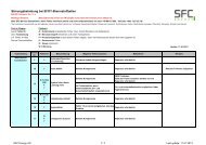
1.1<br />
Komponentenliste pro PoleFix<br />
List of components for each PoleFix<br />
3<br />
1x 1x<br />
1x 1x<br />
1x 1x<br />
5<br />
1 2 3 4 4 5 6<br />
SW 80 KD 95 SCHOTT Mono 190<br />
STP 190<br />
1<br />
9 10<br />
7 8 7 8 7<br />
8<br />
9 10<br />
5<br />
2<br />
4<br />
6 8 7<br />
4x 4x 4x 4x 2x 2x<br />
3x 3x<br />
2
1. Systemkomponenten, Werkzeuge und Hilfsmittel<br />
System components, tools and utilities<br />
PoleFix - L Montageanleitung - Mounting instruction • 03/2012<br />
Sechskantschraube<br />
Hexagon bolt<br />
M10x25<br />
26 x (SCHOTT Mono 190 / STP 190)<br />
34 x (KD 95 / SW 80)<br />
6 x Innensechskantschraube<br />
6 x Hexagon socket screw<br />
M10x35<br />
32 x (<strong>KD95</strong>)<br />
16 x (SW80)<br />
Scheibe M6<br />
Washer M6<br />
16 x (<strong>KD95</strong>)<br />
8 x (SW80)<br />
Sechskantmutter M6<br />
Hexagon nut M6<br />
Scheibe<br />
Washer<br />
M10<br />
32 x (SCHOTT Mono 190 / STP 190)<br />
40 x (KD 95 / SW 80)<br />
16 x (<strong>KD95</strong>)<br />
8 x (SW80)<br />
Innensechskantschraube<br />
Hexagon socket screw<br />
M6x20<br />
16 x (Schott Mono190)<br />
16 x (STP190)<br />
Scheibe M8<br />
Washer M8<br />
8 x (Schott Mono 190)<br />
8 x (STP190)<br />
Sechskantmutter M8<br />
Hexagon nut M8<br />
Mutter<br />
Hexagon nut<br />
M10<br />
32 x (SCHOTT Mono 190 / STP 190)<br />
40 x (KD 95 / SW 80)<br />
4 x (Schott Mono190)<br />
4 x (STP190)<br />
Innensechskantschraube<br />
Hexagon socket screw<br />
M8x20<br />
3
2. Montage des PoleFix<br />
Mounting of the PoleFix<br />
PoleFix - L Montageanleitung - Mounting instruction • 03/2012<br />
2.1 2.2<br />
1<br />
2.3<br />
5<br />
3<br />
10<br />
4<br />
6<br />
2<br />
4
2. Montage des PoleFix<br />
PoleFix - L Montageanleitung - Mounting instruction • 03/2012<br />
2.4<br />
2.5<br />
Mounting of the PoleFix<br />
9<br />
5<br />
8
2. Montage des PoleFix<br />
Mounting of the PoleFix<br />
PoleFix - L Montageanleitung - Mounting instruction • 03/2012<br />
2x KD 95<br />
2x SW 80<br />
6
2. Montage des PoleFix<br />
PoleFix - L Montageanleitung - Mounting instruction • 03/2012<br />
STP 190<br />
SCHOTT Mono 190<br />
7
2. Montage des PoleFix<br />
PoleFix - L Montageanleitung - Mounting instruction • 03/2012<br />
2.6<br />
2.7<br />
Mounting of the PoleFix<br />
KD 95 / SW 80 SCHOTT Mono 190 / STP 190<br />
7<br />
8
2. Montage des PoleFix<br />
PoleFix - L Montageanleitung - Mounting instruction • 03/2012<br />
2.8<br />
2.9<br />
Mounting of the PoleFix<br />
9
!<br />
3. Sicherheitshinweise<br />
PoleFix - L Montageanleitung - Mounting instruction • 03/2012<br />
In diesem Kapitel geben wir Ihnen einen Überblick über die wichtigsten Sicherheitsinformationen. Bitte befolgen<br />
Sie zu Ihrer eigenen Sicherheit und zum Schutz Dritter die folgenden Regeln zur Montage sowie die einschlägigen<br />
Richtlinien für sicheres und fachgerechtes Arbeiten.<br />
3.1 Allgemeine Sicherheitshinweise<br />
Lesen Sie bitte alle Sicherheitshinweise und beachten Sie die aufgeführten Montageanweisungen, bevor Sie den<br />
Masthalter PoleFix zum ersten Mal installieren. Ein Nichtbeachten der Montage- und Sicherheitshinweise kann zu<br />
Verletzungen und anderen Schäden führen. Bitte bewahren Sie die Montageanleitung stets griffbereit auf.<br />
Notwendigkeit fachgerechter Planung<br />
Stellen Sie vor der Montage des Bodengestells sicher, dass eine fachgerechte Planung der Photovoltaik-Anlage<br />
hinsichtlich Ausrichtung, Anordnung der Module, Auslegung des Montagesystems und Elektroplanung sowie die<br />
Klärung aller baulichen Gegebenheiten voraus geht.<br />
Installation nur durch qualifiziertes Fachpersonal<br />
Lassen Sie alle Installationsarbeiten ausschließlich von entsprechend qualifizierten Personen durchführen.<br />
Statische Prüfung der Modulträgerkonstruktion:<br />
Durch die Installation einer Photovoltaikanlage wird die Belastung auf die Mastkonstruktion verändert. Führen Sie<br />
deshalb auch für bestehende Masten eine statische Prüfung gemäß der gültigen DIN-Normen (DIN 1045-1<br />
Betonbau, DIN 1052 Holzbau, DIN 1053 Mauerwerksbau, DIN 1055 Lastannahmen, DIN 18800 Stahlbau etc.)<br />
unbedingt durch.<br />
Montageanleitung für Solarmodultragesystem und Modulmontage<br />
In dieser Montageanleitung finden Sie alle Beschreibungen, die Sie für die Montage des Bodengestells einschließlich<br />
Modulmontage benötigen. Es erfolgt ausdrücklich keine vollständige Darstellung der gesamten Anlageninstallation.<br />
Statiknachweis gilt nur für Deutschland<br />
Ermitteln Sie die Lastanforderungen für Wind und Schnee mittels der DIN 1055 Teil 4 und 5. Der Statiknachweis<br />
gilt somit nur für Anlagen, die Sie in Deutschland errichten. Sollten Sie in einem anderen Land eine Photovoltaikanlage<br />
errichten wollen, so bitten wir um Kontaktaufnahme mit Ihrem Energiebau Kundenbetreuer.<br />
Keine Zweckentfremdung der Bauteile<br />
Verwenden Sie alle Bauteile ausschließlich zur Befestigung von <strong>Solarmodule</strong>n. Das Anbringen anderer Bauelemente<br />
jedweder Art sowie das Bauen von Sicherheitseinrichtungen wie Gerüsten und ähnlichem sind mit bzw. an<br />
der Befestigung der <strong>Solarmodule</strong> ausdrücklich nicht erlaubt.<br />
Schutz vor scharfen Ecken und Kanten<br />
Entfernen Sie eventuelle Grate von den Schnittkanten, um das Verletzungsrisiko durch scharfe Ecken und Kante zu<br />
vermeiden.<br />
10
3. Sicherheitshinweise<br />
PoleFix - L Montageanleitung - Mounting instruction • 03/2012<br />
3.2 Beachtung von Normen und Vorschriften<br />
Beachten Sie insbesondere die Sicherheitshinweise der folgenden Regelwerke:<br />
VDE-Bestimmungen und DIN Normen:<br />
• DIN VDE 0100: Errichtung von Starkstromanlagen mit Nennspannungen bis 1000 V<br />
• DIN VDE 0100-712: Errichten von Niederspannungsanlagen (Photovoltaik-Stromversorgungssysteme)<br />
• VDI 6012 – Blatt 2: Dezentrale Energiesysteme im Gebäude – Photovoltaik<br />
• DIN EN 62305: Blitzschutz<br />
VDEW- und VDN-Richtlinien:<br />
• VDEW-Richtlinie: Eigenerzeugungsanlagen am Niederspannungsnetz<br />
• VDN-Richtlinie: Anhang zur VDEW-Richtlinien: Eigenerzeugungsanlagen am Niederspannungsnetz<br />
Unfallverhütungsvorschriften:<br />
• BGV A1: Unfallverhütungsvorschriften – Prävention<br />
• BGV A2 und A3: Elektrische Anlagen und Betriebsmittel<br />
• BGV C22: Bauarbeiten (Persönliche Schutzausrüstung gegen Absturz)<br />
• BGV D36: Unfallverhütungsvorschrift „Leitern und Tritte“<br />
ACHTUNG:<br />
Für alle Montagearbeiten gelten die Unfallverhütungsvorschriften der Berufsgenossenschaften der Bauwirtschaft.<br />
3.3 Montage der <strong>Solarmodule</strong><br />
ACHTUNG:<br />
Halten Sie die Montagehinweise der Modulhersteller in jedem Fall zur Wahrung etwaiger Gewährleistungsansprüche<br />
ein. Dies betrifft insbesondere die Positionen der Befestigungspunkte. Betreten oder belasten Sie<br />
die <strong>Solarmodule</strong> auf keinen Fall. Es besteht sonst Bruchgefahr.<br />
Das Anzugsmoment der Schrauben M8 beträgt 16 Nm. Bitte berücksichtigen Sie unbedingt die Stabilität des<br />
Modulrahmens, um Verformungen des Rahmens mit möglichen Modulschäden zu vermeiden.<br />
11
!<br />
!<br />
!<br />
!<br />
3. Sicherheitshinweise<br />
PoleFix - L Montageanleitung - Mounting instruction • 03/2012<br />
Elektrischer Modulanschluss<br />
Sicherheitshinweis:<br />
Bereits bei geringer Einstrahlung erzeugen die Module ihre volle Spannung. Je nach Anzahl der Module in einem<br />
Strang können Spannungen von mehreren hundert Volt erreicht werden. Hier besteht Lebensgefahr!<br />
Verbinden Sie die <strong>Solarmodule</strong> anhand der vorhandenen Modulanschlussleitungen während der Montage<br />
untereinander mit Hilfe der Steckverbinder. Achten Sie hierbei auf die richtige Polarität. Befestigen Sie die Leitungen<br />
entlang der Profile mittels UV-beständigen Kabelbindern so, dass die Leitungen nicht durchhängen.<br />
Achten Sie darauf, dass die Isolierung der Leitungen nicht durch scharfe Kanten beschädigt wird. Kontrollieren Sie<br />
zum Abschluss der Arbeiten bitte an den Strangleitungen die ordnungsgemäße Leerlaufspannung.<br />
Planung der Stringleitungen<br />
Planen Sie vor der Montage die Stringverlegung zwischen <strong>Solarmodule</strong>n und Wechselrichter bzw. Laderegler.<br />
Legen Sie Plus- und Minusleitungen möglichst nahe beieinander, um Einkopplungen von Überspannungen zu<br />
vermeiden. Achten Sie darauf, dass die zwischen den Leitungen gebildete Fläche möglichst klein ist. Um<br />
eine dauerhafte Fixierung am Montagegestell zu gewährleisten, liefert Ihnen die Energiebau Solarstromsysteme<br />
GmbH Kabelbinderblöcke und UV-beständige Kabelbinder.<br />
Stellen Sie sicher, dass alle Kabel und Kabelverbindungen gemäß DIN VDE 0100-712.522.8.1 ausgeführt<br />
werden (erd- und kurz-schlussfeste Verlegung).<br />
Statten Sie die Enden der Gleichstromleitungen mit Steckverbindern aus. Hierfür können wir Ihnen von diversen<br />
Herstellern Crimpzangen und Montagewerkzeuge oder entsprechende vorkonfektionierte Adapter-Sets liefern<br />
Planung von Blitzschutz und Erdung<br />
Führen Sie zur Ableitung von Überspannungen einen Potenzialausgleich des Solargenerators durch. Verbinden Sie<br />
dazu das Montagegestell mit der vorhandenen Blitzschutzvorrichtung. Zur Erdung des Solargenerators bieten wir<br />
Ihnen die benötigte Erdungsleitung (H07-VK 16 mm²) und einen Staberder an.<br />
Wenn in unmittelbarer Nähe eine Blitzschutzanlage vorhanden ist, müssen Sie zwingend die Solaranlage in das<br />
Blitzschutzkonzept mit einbeziehen. In diesem Fall empfehlen wir Ihnen die Zusammenarbeit mit einem Blitzschutzfachbetrieb.<br />
Bitte beachten Sie die europäische Norm DIN EN 62305 (VDE 0185).<br />
12
!<br />
3. Safety instructions<br />
PoleFix - L Montageanleitung - Mounting instruction • 03/2012<br />
This chapter provides an overview of the most important safety information. For your safety and the safety of<br />
others, please observe the following rules for installation and the pertinent regulations for safe and proper work<br />
3.1 General safety instructions<br />
Please read all the safety instructions and observe the listed installation instructions before installing the PoleFix<br />
mast bracket for the first time. Failure to observe the installation and safety instructions may result in injury or<br />
other damage. Always keep the installation instructions close at hand.<br />
Necessity for proper planning<br />
Before installing the solar module mounting system, ensure that professional planning of the photovoltaic system<br />
is carried out with regard to orientation, module alignment, construction of the installation system and electrical<br />
planning as well as clarification of all construction conditions.<br />
Installation by qualified professionals only<br />
All installation work is to be carried out exclusively by persons with appropriate qualifications.<br />
Structural inspection of the module mounting design<br />
The installation of a photovoltaic system changes the load on the mast construction. You must therefore undertake<br />
a structural inspection of existing masts in accordance with the applicable DIN standards (DIN 1045-1 concrete<br />
construction, DIN 1052 timber construction, DIN 1053 masonry construction, DIN 1055 load assumptions, DIN<br />
18800 steel construction, etc.).<br />
Installation instructions for solar module mounting systems and module installation<br />
In these installation instructions, you will find all the descriptions necessary for the installation of the solar module<br />
mounting system including module installation. This is expressly not a complete description of the entire system<br />
installation.<br />
Structural data verification applies only for Germany<br />
Determine the load requirements for wind and snow using DIN 1055 Parts 4 and 5. The structural data verification<br />
therefore applies only to systems which you erect in Germany. Should you wish to erect a photovoltaic system<br />
in another country, we ask that you contact your Energiebau customer adviser.<br />
No improper use of components<br />
Use all the components exclusively for fixing solar modules. The attachment of other components of any nature as<br />
well as the construction of safety measures such as scaffolding and similar on the solar module fixtures are<br />
expressly prohibited.<br />
Protection against sharp corners and edges<br />
Remove any burrs from leading edges to reduce the risk of injury due to sharp corners and edges.
3. Safety instructions<br />
PoleFix - L Montageanleitung - Mounting instruction • 03/2012<br />
3.2 Observance of regulations and standards<br />
Particular attention is to be paid to the safety instructions contained in the following regulations:<br />
VDE regulations and DIN standards:<br />
• DIN VDE 0100: Installation of high-voltage systems with rated voltages up to 1,000 V<br />
• DIN VDE 0100-712: Erection of low-voltage systems (photovoltaic power supply systems)<br />
• VDI 6012 – Sheet 2: Decentralised energy systems in buildings – photovoltaic<br />
• DIN EN 62305: Lightning protection<br />
VDEW and VDN regulations:<br />
• VDEW directive: Own generations systems on the low-voltage grid<br />
• VDN directive: Appendix to the VDEW directives: Own generation systems on the low-voltage grid<br />
Rules for the prevention of accidents:<br />
• BGV A1: Rules for the prevention of accidents – prevention<br />
• BGV A2 and A3: Electrical systems and equipment<br />
• BGV C22: Building work (personal safety equipment to prevent falling)<br />
• BGV D36: Accident prevention regulations ‘ladders and steps’<br />
NOTE:<br />
The accident preventions regulations stipulated by the German Accident Prevention & Insurance Association of the<br />
Building Industry apply to all installation work.<br />
3.3 Installation of solar modules<br />
NOTE:<br />
To ensure that possible warranty claims are not invalidated, the installation instructions provided by the<br />
module manufacturer are to be followed in all cases. This particularly applies to the positioning of the<br />
attachment points. Under no circumstances should you step on or place loads on the solar modules. There is<br />
a risk of breakage.<br />
The tightening torque of the M8 screws is 16 Nm. It is imperative that you take into consideration the stability<br />
of the module frame in order to avoid deformation of the frame with possible damage to the module.
!<br />
!<br />
!<br />
!<br />
3. Safety instructions<br />
PoleFix - L Montageanleitung - Mounting instruction • 03/2012<br />
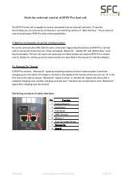
Electrical connection of modules<br />
Safety instruction<br />
The modules generate their full voltage even with low levels of irradiation. Depending on the number of modules<br />
in a row, it is possible to reach voltages of several hundred volts. There is a significant risk of fatal injury.<br />
During installation, connect the solar modules together using the existing module-connecting cables and sockets.<br />
Ensure the polarity is correct. Fix the cables along the profiles using UV-resistant cable binders so that the cables do<br />
not sag.<br />
Ensure that the cable insulation cannot be damaged by sharp edges. Check the proper open circuit voltage on the<br />
cabling after completing this work.<br />
Planning the cabling<br />
Before installation, plan the laying of cabling between the solar modules and inverters or charge controllers. Lay<br />
the plus and minus cables as close together as possible to avoid coupling of electrical surges. Ensure that the<br />
area formed between the cables is as small as possible. In order to guarantee long-lasting anchorage on the<br />
mounting frame, Energiebau Solarstromsysteme GmbH will supply you with cable binder housings and UV-resistant<br />
cable binders.<br />
Ensure that all cables and cable connections are made in accordance with DIN VDE 0100-712.522.8.1 (laying of<br />
cables for protection against accidental earthing and short-circuits).<br />
Fit the ends of the DC cables with plug connectors. For this, we can provide you with crimping tools and installation<br />
tools from various manufacturers or appropriate prefabricated adapter sets.<br />
Planning of lightning protection and potential equalisation<br />
Carry out potential equalisation of the solar generator to dissipate electrical surges. To do this, connect the<br />
mounting frame with the existing lightning arrester. We can supply you with the necessary earth conductor (H07-<br />
VK 16 mm²) and an earthing rod to earth the solar generator.<br />
If there is a lightning protection system nearby, it is essential that the solar power system is included in the lightning<br />
protection plan. In this case, we recommend that you consult a lightning protection specialist. European<br />
standard DIN EN 62305 (VDE 0185) is to be observed.
www.energiebau.de<br />
PoleFix - L Montageanleitung - Mounting instruction • 03/2012<br />
alle Bildrechte bei Energiebau - Copyright by Energiebau<br />
Energiebau<br />
Solarstromsysteme GmbH<br />
Heinrich-Rohlmann-Str. 17<br />
50829 Köln<br />
Tel.: +49(0)221 98966-0<br />
Fax: +49(0)221 98966-291<br />
e-mail: off-grid@energiebau.de<br />
16