Wall thickness 45 mm - HESSEL Ingenieurtechnik GmbH, Roetgen
Wall thickness 45 mm - HESSEL Ingenieurtechnik GmbH, Roetgen
Wall thickness 45 mm - HESSEL Ingenieurtechnik GmbH, Roetgen

Sie wollen auch ein ePaper? Erhöhen Sie die Reichweite Ihrer Titel.
YUMPU macht aus Druck-PDFs automatisch weboptimierte ePaper, die Google liebt.
spannungsbezogener Kerbfaktor fkó [-] /<br />
Stress-related notch factor fkó [-]<br />
Kerbfaktor/<br />
Notch factor<br />
Schweißfaktor/<br />
Welding factor<br />
Schweißfaktor/<br />
Welding factor<br />
Schweißfaktor/<br />
Welding factor<br />
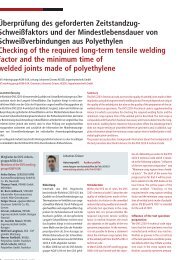
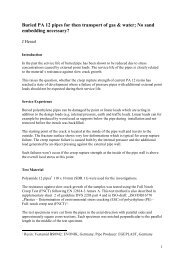
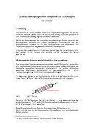
Bild 2: Vergleich des spannungsbezogenen Schweißfaktors und des spannungsbezogenen<br />
Kerbfaktors von Proben mit Außenkerben aus der PE 80 Platte<br />
Fig. 2: Comparision of the stress-related welding factor and the stress<br />
related notch factor for notched specimens from a PE 80 sheet<br />
verbindungen zeigt, dass bei fachgerecht<br />
ausgeführten Schweißverbindungen<br />
(z. B. Heizelementstumpfschweißungen<br />
nach Richtlinie DVS 2207-1) der<br />
Zeitstandbruch i<strong>mm</strong>er von der Kerbe<br />
zwischen dem Schweißwulst und der<br />
Oberfläche des Halbzeuges ausgeht und<br />
sich der Riss dann durch das ungeschweißte<br />
Material fortsetzt (Bild1).<br />
Dieses typische Bruchverhalten wurde<br />
bisher im Wanddickenbereich von 10<br />
<strong>mm</strong> bis 70 <strong>mm</strong> beobachtet.<br />
Obwohl der eigentliche Schweißvorgang<br />
in der Fügeebene in einer Tiefe<br />
von weniger als 0,1 µm stattfindet, ist<br />
das Langzeitbruchverhalten – beeinflusst<br />
durch den mittragenden Wulst –<br />
hier günstiger als das Langzeitbruchverhalten<br />
des ungeschweißten Materials<br />
unter dem Einfluss der Wulstkerbe.<br />
Demgemäß wird bei Schweißverbindungen<br />
nach DVS 2207-1 die Standzeit der<br />
Verbindung durch die „Schärfe“ der<br />
Wulstkerbe einerseits und den Widerstand<br />
des Grundmaterials gegenüber<br />
langsamem Rissfortschritt („Kerbempfindlichkeit“)<br />
andererseits besti<strong>mm</strong>t.<br />
Im Bild 2 sind einige Ergebnisse von<br />
Untersuchungen zur Quantifizierung der<br />
Wulstkerbe bei Heizelementstumpfschweißungen<br />
gezeigt. Es ergab sich für<br />
ein PE 80 (HD) ein wirksamer Radius im<br />
Kerbgrund von ca. 0,25 <strong>mm</strong> [3]. Bei diesen<br />
Untersuchungen wurde die sich beim<br />
Heizelementstumpfschweißen bildende<br />
Wulstkerbe durch definierte Außenkerben<br />
an ungeschweißten Proben (z. B.<br />
„spitze Kerbe“ oder „Rundkerbe“) simuliert.<br />
Der Schweißfaktor und der Kerbfaktor<br />
sind gleichsinnig definiert.<br />
Der Fügedruck nach DVS 2207-1 wur-<br />
162 JOINING PLASTICS 2/07<br />
Kerbradius [<strong>mm</strong>] / Notch radius [<strong>mm</strong>]<br />
Schweißfaktoren /<br />
Welding factors<br />
Kerbradius [<strong>mm</strong>] / Notch radius [<strong>mm</strong>]<br />
-- Licensed for Joachim Hessel --<br />
Prüfbedingungen: /<br />
Welding factors:<br />
Bezugsspannung: 4 N/<strong>mm</strong> 2<br />
Reference stress: 4 N/<strong>mm</strong> 2<br />
Prüftemperatur: 80 °C<br />
Test temperature: 80 °C<br />
Medium: 2 Gew. % Teepol NM3<br />
Medium: 2 by weight % Teepol<br />
NM3<br />
Proben mit Außenkerben und<br />
Schweißproben<br />
Specimens with external<br />
notches and welded specimens<br />
Restbreite 10 <strong>mm</strong><br />
Residual width 10 <strong>mm</strong><br />
de variiert. Dabei bedeutet „X“ im Bild<br />
2 das Vielfache des Fügedrucks nach<br />
DVS 2207-1.<br />
Es hat sich gezeigt, dass sich die Schärfe<br />
der Wulstkerbe bei den untersuchten<br />
Schweißungen nur in geringem (z. B.<br />
durch den Schweißdruck) Umfang<br />
beeinflussen lässt. Demzufolge ist die<br />
größte Einflussmöglichkeit auf die<br />
Standzeit der Schweißverbindung durch<br />
den Widerstand des Grundmaterials<br />
gegenüber langsamem Rissfortschritt<br />
(„Kerbempfindlichkeit“) gegeben.<br />
Die von NEUBER für metallische Werkstoffe<br />
gefundenen Gesetzmäßigkeiten<br />
zur Spannungsüberhöhung bei Werkstoffanhäufungen<br />
bzw. Kerben [4] können<br />
sinngemäß auch auf das Langzeitverhalten<br />
von PE-Schweißverbindungen<br />
übertragen werden, wenn der Bruch<br />
nicht in der Fügeebene stattfindet.<br />
Eine geeignete Methode zur Besti<strong>mm</strong>ung<br />
der Kerbempfindlichkeit von Polyethylen<br />
ist der Full Notch Creep Test (FNCT).<br />
Dieser ursprünglich in Japan zur Charakterisierung<br />
von Polyethylen-Werkstoffen<br />
entwickelte Versuch zeichnet<br />
sich bei entsprechend sorgfältiger<br />
Durchführung durch eine hohe Reproduzierbarkeit<br />
und Präzision aus.<br />
In der Europäischen Norm DIN EN<br />
12814-3 (10/2005) wird bei der Prüfung<br />
von Schweißverbindungen auf den<br />
Zusa<strong>mm</strong>enhang zwischen Kerbempfindlichkeit<br />
des Grundmaterials und Langzeitbruchverhalten<br />
von Schweißverbindungen<br />
wie folgt hingewiesen:<br />
„Das Bruchverhalten der Schweißverbindungen,<br />
bei denen der Bruch im<br />
Grundwerkstoff auftritt und von der<br />
Kerbstelle zwischen Grundwerkstoff und<br />
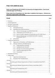
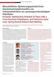
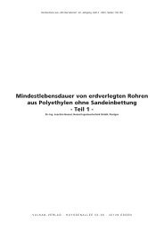
Standzeit in Stunden / Service life in hours<br />
Prüfmethode: /<br />
Test method:<br />
ACT-Verfahren /<br />
ACT procedure<br />
Bild 3: Zusa<strong>mm</strong>enhang zwischen Kerbempfindlichkeit und Langzeitbruchverhalten<br />
von Schweißverbindungen im ACT-Verfahren<br />
Fig. 3: Relation between notch sensitivity and long term creep rupture<br />
behaviour of welded joints in the ACT-test procedure (RCplus = PE 100-RC)<br />
propagates through the parent material<br />
(Fig. 1).<br />
This typical failure behaviour has been<br />
observed for wall <strong>thickness</strong>es from 10<br />
<strong>mm</strong> to 70 <strong>mm</strong>.<br />
Although the welding in the fusion<br />
plane occurs to a depth of less than 0.1<br />
Ìm, the creep rupture time in this area<br />
is better – due to the larger cross section<br />
because of the beads – than the<br />
creep rupture time of the unwelded<br />
material under the influence of the<br />
notch between the bead and the surface<br />
of the parent material.<br />
For this reason the time-to-rupture of<br />
welded joints produced according to<br />
DVS 2207-1 depends on a combination<br />
of the “sharpness” of the notch at the<br />
bead and the resistance to slow crack<br />
growth (“stress crack resistance”) of<br />
the parent material.<br />
Some results of an investigation to<br />
quantify the sharpness of the notch<br />
between the bead and the surface of<br />
the parent material of heated tool butt<br />
welded joints are given in fig. 2. The<br />
effective notch tip radius at butt welded<br />
PE 80 joints was found to be approx.<br />
0.25 <strong>mm</strong> [3].The notch at the bead was<br />
simulated by different notch tip radii in<br />
unwelded specimens (e. g. „sharp<br />
notch“ or „circular notch”). The longterm<br />
welding factor is defined as the<br />
ratio of the stress value of the weld and<br />
of the parent material at identical failure<br />
times.The long-term notch factor is<br />
defined as the ratio of the stress value<br />
of the notched specimen and of the parent<br />
material at identical failure times.<br />
In order to produce different notch tip<br />
radii at the beads the welding pressure<br />
FNCT / FNCT Schweißung / Welding<br />
according to DVS 2207-1 was varied.<br />
The “X” in fig. 2 represents the factor<br />
that was used to multiply the „normal“<br />
welding pressure according to DVS<br />
2207-1.<br />
In this investigation it was observed that<br />
the welding pressure has only a limited<br />
influence on the sharpness of the<br />
notch at the bead.Therefore the resistance<br />
to slow crack growth of the parent<br />
material is the most important factor<br />
in determining the creep rupture<br />
time of welded joints.<br />
The formulas established by NEUBER<br />
for metallic materials to describe the<br />
stress peak at material accumulation or<br />
notches [4] can be transferred to the<br />
long-term behaviour of welded joints<br />
made from PE as long as the failure does<br />
not occur in the fusion plane.<br />
A suitable method to determine the<br />
notch sensitivity of polyethylene is the<br />
Full Notch Creep Test (FNCT).<br />
The FNCT - originally developed in Japan<br />
in order to characterize polyethylene<br />
resins - provides high reproducability<br />
and precision as long as the test is performed<br />
carefully.<br />
In the European Standard EN 12814-3<br />
(10/2005) where the long-term testing<br />
of welded joints is described the following<br />
information about the relation<br />
between the notch sensitivity of the parent<br />
material and the creep rupture<br />
behaviour of welded joint is given:<br />
„The fracture behaviour of welded joints,<br />
where fracture occurs in the parent material<br />
and is initiated from notch between<br />
the parent material and the weld bead<br />
is closely related to the resistance to slow<br />
crack growth of the parent material.