Buried PA 12 pipes for then transport of gas & water; No sand ...
Buried PA 12 pipes for then transport of gas & water; No sand ...
Buried PA 12 pipes for then transport of gas & water; No sand ...

Create successful ePaper yourself
Turn your PDF publications into a flip-book with our unique Google optimized e-Paper software.
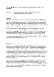
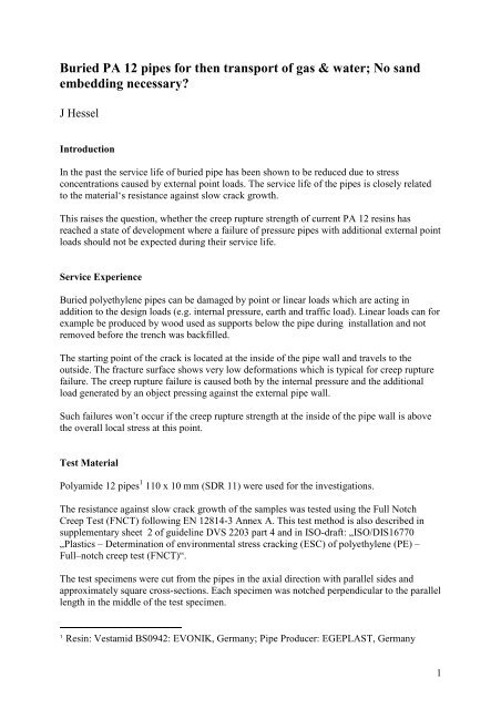
<strong>Buried</strong> <strong>PA</strong> <strong>12</strong> <strong>pipes</strong> <strong>for</strong> <strong>then</strong> <strong>transport</strong> <strong>of</strong> <strong>gas</strong> & <strong>water</strong>; <strong>No</strong> <strong>sand</strong><br />
embedding necessary?<br />
J Hessel<br />
Introduction<br />
In the past the service life <strong>of</strong> buried pipe has been shown to be reduced due to stress<br />
concentrations caused by external point loads. The service life <strong>of</strong> the <strong>pipes</strong> is closely related<br />
to the material‘s resistance against slow crack growth.<br />
This raises the question, whether the creep rupture strength <strong>of</strong> current <strong>PA</strong> <strong>12</strong> resins has<br />
reached a state <strong>of</strong> development where a failure <strong>of</strong> pressure <strong>pipes</strong> with additional external point<br />
loads should not be expected during their service life.<br />
Service Experience<br />
<strong>Buried</strong> polyethylene <strong>pipes</strong> can be damaged by point or linear loads which are acting in<br />
addition to the design loads (e.g. internal pressure, earth and traffic load). Linear loads can <strong>for</strong><br />
example be produced by wood used as supports below the pipe during installation and not<br />
removed be<strong>for</strong>e the trench was backfilled.<br />
The starting point <strong>of</strong> the crack is located at the inside <strong>of</strong> the pipe wall and travels to the<br />
outside. The fracture surface shows very low de<strong>for</strong>mations which is typical <strong>for</strong> creep rupture<br />
failure. The creep rupture failure is caused both by the internal pressure and the additional<br />
load generated by an object pressing against the external pipe wall.<br />
Such failures won’t occur if the creep rupture strength at the inside <strong>of</strong> the pipe wall is above<br />
the overall local stress at this point.<br />
Test Material<br />
Polyamide <strong>12</strong> <strong>pipes</strong> 1 110 x 10 mm (SDR 11) were used <strong>for</strong> the investigations.<br />
The resistance against slow crack growth <strong>of</strong> the samples was tested using the Full <strong>No</strong>tch<br />
Creep Test (FNCT) following EN <strong>12</strong>814-3 Annex A. This test method is also described in<br />
supplementary sheet 2 <strong>of</strong> guideline DVS 2203 part 4 and in ISO-draft: „ISO/DIS16770<br />
„Plastics – Determination <strong>of</strong> environmental stress cracking (ESC) <strong>of</strong> polyethylene (PE) –<br />
Full–notch creep test (FNCT)“.<br />
The test specimens were cut from the <strong>pipes</strong> in the axial direction with parallel sides and<br />
approximately square cross-sections. Each specimen was notched perpendicular to the parallel<br />
length in the middle <strong>of</strong> the test specimen.<br />
1 Resin: Vestamid BS0942: EVONIK, Germany; Pipe Producer: EGEPLAST, Germany<br />
1
The specimens were loaded by a constant tensile stress between 14 and 8 ± 0,05 N/mm²<br />
relating to the remaining unnotched cross-sections. The deviation from the nominal test<br />
temperature was ± 0.2 K.<br />
The tensile creep tests were per<strong>for</strong>med on 3 test specimens per temperature using an aqueous<br />
solutions <strong>of</strong> NM 5 (mixture <strong>of</strong> anionic and kationic tensides) in demineralised <strong>water</strong> (2/100,<br />
w/w).<br />
Principle and Limiting Conditions <strong>of</strong> the Tests<br />
External Point Load<br />
The maximum stress that the pipe material will experience from a point load is the yield<br />
stress. There<strong>for</strong>e in this test it was ensured that the displacement <strong>of</strong> the point load into the<br />
pipe wall was sufficient to cause yielding <strong>of</strong> the material at the inside <strong>of</strong> the pipe.<br />
Since the additional stress in the pipe wall far from the point <strong>of</strong> load will be zero all possible<br />
stresses that might occur in the field due to a pint load are represented in this test.<br />
There are two scenario which are not covered: One the penetration <strong>of</strong> a sharp object - e.g. a<br />
nail – through the pipe wall and two the complete crushing <strong>of</strong> the pipe, e.g. by a large rock. In<br />
the last case the pipe is no longer functioning, but the <strong>for</strong>ce on the pipe is comparable to the<br />
test load in the point loading test.<br />
The required surface elongation at the inner pipe wall (i.e. the above yield elongation) was<br />
produced by the displacement <strong>of</strong> a tool along the radius <strong>of</strong> the pipe with a tool tip radius <strong>of</strong> 5<br />
mm. The tool loading was carried out at room temperature with no internal pressure in the<br />
pipe. The tool was loaded until a cord with a length <strong>of</strong> 5 mm was measured at the inside<br />
surface <strong>of</strong> the pipe (fig. 1).<br />
Pipe Wall<br />
10<br />
5<br />
Chord<br />
Constant<br />
Displacement<br />
Fig. 1: Loading by an external point load be<strong>for</strong>e starting the internal pressure test<br />
The elongation at the inside surface can be calculated using the following equation:<br />
ε = [0,318 * F * R] / [b‘ * s * E(t)]<br />
2
where:<br />
ε Elongation at the inner surface <strong>of</strong> the pipe wall<br />
F Radial acting <strong>for</strong>ce (single load)<br />
R Mean pipe radius<br />
s Wall thickness<br />
E(t) E-modulus<br />
b‘ Supporting width<br />
The supporting width <strong>of</strong> the load (b') can be determined experimentally by measuring the<br />
<strong>for</strong>ce on the tool with the pipe under internal pressure.<br />
Finite element calculations (fig. 2) confirm that the tool loading with a pipe under internal<br />
pressure <strong>of</strong> 8 bar exceeds the yield elongation <strong>of</strong> <strong>PA</strong> <strong>12</strong> which is at 6 %.<br />
-1,2<br />
1,6<br />
4,4<br />
21,2<br />
7,2<br />
15,6<br />
10 mmm<br />
Fig. 2: Edge fiber expansion in % at the inside wall <strong>of</strong> the pipe due to an external point load<br />
and an internal pressure <strong>of</strong> 8 bar<br />
The internal pressure <strong>of</strong> the <strong>pipes</strong> was chosen to produce a hoop stress <strong>of</strong> 10 N/mm² at 80 °C<br />
during the testing (ISO 1167).<br />
Test Temperatures and Medium<br />
ε ε<br />
The tests were per<strong>for</strong>med at 80 °C, 60 °C and 40 °C.<br />
To accelerate the tests they were per<strong>for</strong>med using an aqueous solution <strong>of</strong> 2 % detergent and<br />
demineralised <strong>water</strong>. The test fluid was continuously mixed in the <strong>pipes</strong> to prevent separation.<br />
3
Failure Mechanism<br />
Assuming that the process <strong>of</strong> slow crack growth (stress cracking) is the relevant long term<br />
failure mode at <strong>pipes</strong> under additional external point load the resistance against stress<br />
cracking is tested in FNCT.<br />
Results<br />
FNCT<br />
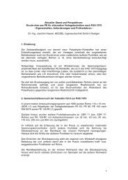
The FNCT’s were per<strong>for</strong>med in the range between 16 and 8 N/mm². There are obviously two<br />
parts <strong>of</strong> the creep rupture curve (fig. 3). In the flat part (between 16 and 14 N/mm²) the ductile<br />
failure mode dominates (fig. 4).<br />
At a test stress <strong>of</strong> 8 N/mm² typical brittle failure mode can be observed (fig. 5).<br />
Tensile Stress in N/mm²<br />
17,0<br />
15,0<br />
14,0<br />
13,0<br />
11,0<br />
9,0<br />
Water; 80 °C<br />
NM 5; 80 °C<br />
Acelleration Factor: 34,2<br />
NMH<br />
Water<br />
7,0<br />
10 30 100 300 1000 3000 10000<br />
Rupture time in Hours<br />
Fig. 3: Creep rupture <strong>of</strong> <strong>PA</strong> <strong>12</strong> in the FNCT at 80 °C<br />
Fig. 4: Fracture surface <strong>of</strong> a FNCT-specimen taken from a <strong>PA</strong> <strong>12</strong>-pipe (16 N/mm²)<br />
4
Fig. 5: Fracture surface <strong>of</strong> a FNCT-specimen taken from a <strong>PA</strong> <strong>12</strong>-pipe (8 N/mm²)<br />
Point loading tests<br />
The specimens tested in the point loading tests did not fail up to the end <strong>of</strong> July 2008 and<br />
have a testing time <strong>of</strong> 4500 hours at 80 °C.<br />
The final results should be available at the date <strong>of</strong> the presentation.<br />
Conclusion<br />
The installation <strong>of</strong> <strong>PA</strong> <strong>12</strong>-<strong>pipes</strong> <strong>for</strong> the <strong>transport</strong> <strong>of</strong> <strong>gas</strong> or <strong>water</strong> without <strong>sand</strong><br />
embedding should be possible if the internal pressure is limited. The critical pressure<br />
will be discussed after all test results are available (at the date <strong>of</strong> the conference).<br />
5