

SERIE DER HYDRAULISCHEN - Adler Maschinen Gmbh
SERIE DER HYDRAULISCHEN - Adler Maschinen Gmbh
SERIE DER HYDRAULISCHEN - Adler Maschinen Gmbh

Erfolgreiche ePaper selbst erstellen
Machen Sie aus Ihren PDF Publikationen ein blätterbares Flipbook mit unserer einzigartigen Google optimierten e-Paper Software.
4<br />
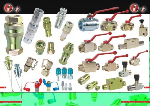
Unsere Produktpalette<br />
Fer-ro / product range<br />
5<br />
Fer-ro / Unsere Produktpalette<br />
Fer-ro / product range
6<br />
<strong>SERIE</strong> <strong>DER</strong> <strong>HYDRAULISCHEN</strong> SCHNELLKUPPLUNGEN<br />
Diese Serie wird aus Stahl hergestellt und galvanisiert. Die männlichen<br />
Verbindungsenden werden außerdem jeweils thermisch behandelt. Bei den<br />
Ausmaßen der Verschraubungen handelt es sich um BSP – Maße. Sie können<br />
unter Nulldruck verbunden und getrennt werden. Als Dichtmaterial werden O-<br />
Ringe aus Nitrilkautschuk (NBR) verwendet, die einem Wärmespektrum von -30°C<br />
bis +110°C standhalten. Wir können auch Viton-Produkte, die für ein<br />
Wärmespektrum von -30°C bis +225°C gebraucht werden, oder aber spezielle<br />
Produkte mit Federausstattung anbieten, welche bei sehr hohen Temperaturen<br />
zweckmäßig sind. Bei Sonderfällen sind Dichtmaterialien aus Silikon (MVQ) u. ä.<br />
angesagt. Im Falle von Aufträgen mit hoher Stückzahl fertigen wir auch im<br />
Rahmen der NPT – Maße bzw. dem metrischen System entsprechend.<br />
Unsere Serie der hydraulischen Schnellverschlusskupplungen wird vor allem in<br />
der Landwirtschaft, in der Automobilbranche, in der Luftfahrt, der Bautechnik und<br />
auf dem Gebiet der militärischen Verteidigung verwendet. Hier findet sie bei<br />
industriellen und mobilen Verfahren, wie z. B. bei den hydraulischen Systemen<br />
von <strong>Maschinen</strong>, Ausrüstungen und Fahrzeugen Anwendung. Besonders als<br />
jeweils schnell hergestellte hydraulische Verbindung zwischen Zugmaschinen<br />
und Anhängern ist diese Serie sehr gefragt.<br />
HYDRAULIC QUICK COUPLING <strong>SERIE</strong>S<br />
Hydraulic Quick Coupling Series made of carbon steel is zinc plated and male<br />
nipples are hardened by applying the heat treatment. The thread size is BSP and<br />
shut-off system is poppet valve. They can be connected and disconnected at<br />
zero pressure. Standard seal material O-Ring is Nitrile Rubber (NBR) suitable for<br />
temperature range from -30 °C to +110 °C. Also Viton, which is ideal for the<br />
temperatures from -30 °C to +225 °C, and special springs resistant to high<br />
temperatures are available on hand. For special cases, upon request Silicone<br />
(MVQ) and other seal elements are also available. NPT and Metric thread sizes<br />
are also available in case of adequate order amount.<br />
Hydraulic Quick Coupling Series is used in many industries mainly in agriculture,<br />
automobile, aviation, construction and defence industries for a wide range of<br />
industrial and mobile hydraulic applications such as vehicles like semitrucks,<br />
Wichtiger Hinweis:<br />
hydraulic systems of machines and equipments.<br />
“ Das NPT – Gewinde darf nicht angezogen<br />
Bei Sonderfällen - Viton<br />
werden, damit keine Risse entstehen, da es sich<br />
bei den Verschraubungsmaßen um BSP handelt<br />
und weil die männlichen Verbindungsenden<br />
wärmebehandelt sind. “<br />
Important Note:<br />
“Screwing NPT thread is not recommended in<br />
order not to be faced with cracking problems<br />
because of male nipples are heat-treaded and<br />
are in BSP thread size.”<br />
FER-RO / DIE <strong>SERIE</strong> <strong>DER</strong> <strong>HYDRAULISCHEN</strong> SCHNELLVERSCHLUSSKUPPLUNGEN<br />
Fer-ro / hydraulıc quıck couplıng serıes<br />
Druckveränderung (bar)<br />
Pressure Drop (Bar)<br />
6<br />
1/4” 3/8” 1/2”<br />
5<br />
4<br />
3<br />
2<br />
1<br />
Kode<br />
(Code)<br />
003000<br />
003004<br />
003008<br />
003015<br />
003019<br />
003023<br />
003026<br />
003029<br />
Kode<br />
(Code)<br />
003000<br />
003004<br />
003008<br />
003015<br />
003019<br />
003023<br />
003026<br />
003029<br />
Verschraubungsmaß<br />
(Thread Size)<br />
1/4” BSP<br />
3/8” BSP<br />
1/2” BSP<br />
3/4” BSP<br />
1” BSP<br />
1 1/4” BSP<br />
1 1/2” BSP<br />
2” BSP<br />
3/4”<br />
0<br />
0 50 100 150 200 250 300 350 400<br />
Diagramm „Durchfluss / Druckveränderung“<br />
Flow Rate / Pressure Drop Table<br />
1/4” BSP<br />
3/8” BSP<br />
1/2” BSP<br />
3/4” BSP<br />
1” BSP<br />
1 1/4” BSP<br />
1 1/2” BSP<br />
2” BSP<br />
Technische Eigenschaften<br />
Technical Specifications<br />
Arbeitsdruck<br />
(Working Pressure)<br />
Bar<br />
350<br />
330<br />
320<br />
280<br />
250<br />
230<br />
220<br />
200<br />
Verschraubungsmaß<br />
(Thread Size) 1 Bar<br />
15<br />
25<br />
50<br />
110<br />
156<br />
240<br />
340<br />
750<br />
Abmessungen - mm<br />
(Dimensions) - mm<br />
A B C D E1 E2<br />
75 55 20 30 19 22<br />
81 61 20 35 22 27<br />
92 68 25 38 27 30<br />
110 82 29 48 36 38<br />
133 100 33 56 41 46<br />
150 117 34 70 50 55<br />
169 134 35 82 60 70<br />
194 156 38 102 75 80<br />
Druckveränderung – ? p (Pressure Drop) - p<br />
6<br />
5<br />
4<br />
3<br />
2<br />
1<br />
2 Bar 5 Bar<br />
22<br />
38<br />
70<br />
165<br />
250<br />
365<br />
475<br />
1025<br />
35<br />
70<br />
135<br />
300<br />
430<br />
650<br />
800<br />
1680<br />
1” 1 1/4” 1 1/2”<br />
0<br />
0 200 400 600 800 1000 1200 1400 1600 1800<br />
Durchfluss (L/min) / Flow Rate (l/mn) Durchfluss (L/min) / Flow Rate (l/mn)<br />
Druckveränderung (bar)<br />
Pressure Drop (Bar)<br />
FER-RO / DIE <strong>SERIE</strong> <strong>DER</strong> <strong>HYDRAULISCHEN</strong> SCHNELLVERSCHLUSSKUPPLUNGEN<br />
Fer-ro / hydraulıc quıck couplıng serıes<br />
2”<br />
7
Wichtiger Hinweis:<br />
“ Das NPT – Gewinde darf nicht angezogen<br />
werden, damit keine Risse entstehen, da es sich<br />
bei den Verschraubungsmaßen um BSP handelt<br />
und weil die männlichen Verbindungsenden<br />
wärmebehandelt sind. “<br />
Important Note:<br />
“Screwing NPT thread is not recommended in<br />
order not to be faced with cracking problems<br />
because of male nipples are heat-treaded and<br />
are in BSP thread size.”<br />
8<br />
<strong>SERIE</strong> <strong>DER</strong> <strong>HYDRAULISCHEN</strong> SCHNELLKUPPLUNGEN MIT FLACHFRONT<br />
Diese Serie wird aus ISO 16028 konformem Stahl hergestellt und galvanisiert. Die Kugellager<br />
werden außerdem jeweils thermisch gehärtet. Bei den Ausmaßen der Verschraubungen<br />
handelt es sich um BSP – Maße. Als Dichtmaterial werden O-Ringe aus Nitrilkautschuk (NBR)<br />
verwendet, die einem Wärmespektrum von -30°C bis +110°C standhalten. Wir können auch<br />
Viton-Produkte, die für ein Wärmespektrum von -30°C bis +225°C gebraucht werden, oder aber<br />
spezielle Produkte mit Federausstattung anbieten, welche bei sehr hohen Temperaturen<br />
zweckmäßig sind. Die automatischen Verschlusskupplungen mit Flachfront können leicht<br />
gereinigt werden. Außerdem haben sie ein Design, dass ein Eindringen von Schmutzpartikeln in<br />
den hydraulischen Kreislauft verhindert. Dieses spezielle Design ermöglicht auch das Verbinden<br />
und Trennen unter Druckverhältnissen und schließt somit beim Verbinden / Trennen das Austreten<br />
von Öl bzw. das Eintreten von Luft und anderen Stoffen ins System aus. Ein spezielles<br />
„Drücksystem“ ermöglicht ein Verbinden / Trennen mit einer Hand und dient der schnellen<br />
Herstellung von Verbindungen. Der manuelle Verschlussmechanismus auf dem Ring dagegen,<br />
sorgt für die Vermeidung von ungewolltem Verbinden / Trennen.<br />
Unsere Serie der automatischen Verschlusskupplungen mit Flachfront wird vor allem bei<br />
<strong>Maschinen</strong> und hydraulischen Fahrzeugen verwendet, die in sensiblen Umfeldern betrieben<br />
werden. Sie weist eine hervorragende Beständigkeit gegen solche Schäden auf, die durch<br />
Fluide mit hoher Durchflussrate und Hydraulikschocks hervorgerufen werden können. Deshalb ist<br />
sie besonders bei mobilen Strukturen, landwirtschaftlichen Ausrüstungen und<br />
Industrieeinrichtungen gefragt, wo sie bei Verfahren mit Vibrationen und hohem Druck<br />
Anwendung findet.<br />
HYDRAULIC FLAT FACE QUICK COUPLING <strong>SERIE</strong>S<br />
ISO 16028 interchange Hydraulic Flat Face Quick Couplings made of solid barstock are zinc plated<br />
and ball racing areas are induction hardened by applying heat treatment. The thread size is BSP and<br />
standard seal material O-ring is Nitrile (NBR) suitable for temperature range from -30 ºC and +110 ºC.<br />
Also Viton, which is ideal for the temperatures from -30 °C to +225 °C, and special springs resistant to<br />
high temperatures are available on hand. Flat Faced Quick Couplings are specially designed for easy<br />
cleaning and preventing the penetration of contamination to the hydraulic circuits. Special desing<br />
which allows connection and disconnection under pressure provides no-spillage of oil and no<br />
inclusion of air or external media during operation. “Push system” requiring only one hand for<br />
operation makes connection and disconnection easy and fast. Manual sleeve locking mechanism<br />
prevents accidental and involuntary connection and disconnection.<br />
The main field of application for Flat Face Quick Couplings is machinery in environment-sensitive<br />
areas and hydraulic tools. Great resistance to pressure peaks preventing damage from high velocity<br />
fluid and hydraulic shock allows applications involving high pressure impulses in mobile construction<br />
and agricultural equipments and general industrial plants.<br />
Fer-ro / DIE <strong>SERIE</strong> <strong>DER</strong> SCHNELLKUPPLUNGEN MıT FLACHFRONT<br />
Fer-ro / hydraulıc flat face quıck couplıng serıes<br />
Kode<br />
(Code)<br />
003200<br />
003210<br />
003220<br />
003230<br />
003240<br />
Kode<br />
(Code)<br />
003200<br />
003210<br />
003220<br />
003230<br />
003240<br />
Verschraubungsmaß<br />
(Thread Size)<br />
1/4” BSP<br />
3/8” BSP<br />
1/2” BSP<br />
3/4” BSP<br />
1” BSP<br />
Diagramm „Durchfluss / Druckveränderung“<br />
Flow Rate / Pressure Drop Table<br />
Verschraubungsmaß<br />
(Thread Size) 1 Bar<br />
1/4” BSP<br />
3/8” BSP<br />
1/2” BSP<br />
3/4” BSP<br />
1” BSP<br />
Technische Eigenschaften<br />
Technical Specifications<br />
Arbeitsdruck<br />
(Working Pressure)<br />
Abmessungen - mm<br />
(Dimensions) - mm<br />
Bar C C1 C2 L L1 P P1<br />
400 27 24,50 28 59 95 24 22<br />
370 30 30 30 75 125 27 27<br />
370 30 30 30 75 125 27 27<br />
350 38 40 40 84 150 36 36<br />
330 48 46 46 101 183 41 41<br />
14<br />
28<br />
55<br />
120<br />
145<br />
Druckveränderung (bar)<br />
Pressure Drop (Bar)<br />
Druckveränderung (Pressure Drop) - p<br />
2 Bar 5 Bar<br />
20<br />
45<br />
75<br />
160<br />
200<br />
40<br />
75<br />
135<br />
250<br />
350<br />
1/4” 3/8” 1/2” 3/4” 1”<br />
Durchfluss (L/min) / Flow Rate (l/mn)<br />
Fer-ro / DIE <strong>SERIE</strong> <strong>DER</strong> SCHNELLKUPPLUNGEN MıT FLACHFRONT<br />
Fer-ro / hydraulıc flat face quıck couplıng serıes<br />
9
<strong>SERIE</strong> <strong>DER</strong> <strong>HYDRAULISCHEN</strong> AUTOMATIKVERSCHLUSSKUPPLUNGEN MIT KUGELVERSCHLUSS<br />
Diese Serie wird aus Stahl hergestellt und galvanisiert. Die männlichen<br />
Verbindungsenden werden außerdem jeweils thermisch behandelt. Bei den<br />
Ausmaßen der Verschraubungen handelt es sich um BSP – Maße, wobei das<br />
Ventilsystem jeweils ein Kugelsystem ist. Sie können unter Nulldruck verbunden<br />
und getrennt werden. Als Dichtmaterial werden O-Ringe aus Nitrilkautschuk<br />
(NBR) verwendet, die einem Wärmespektrum von -30°C bis +110°C<br />
standhalten. Bei Sonderfällen sind Dichtmaterialien aus Viton, Silikon (MVQ) u.<br />
ä. angesagt.<br />
Unsere Serie der hydraulischen Automatikverschlusskupplungen mit<br />
Kugelverschluss wird vor allem in der Landwirtschaft, in der Automobilbranche,<br />
in der Luftfahrt, der Bautechnik und auf dem Gebiet der militärischen<br />
Verteidigung verwendet. Hier findet sie bei industriellen und mobilen Verfahren,<br />
wie z. B. bei den hydraulischen Systemen von <strong>Maschinen</strong>, Ausrüstungen und<br />
Fahrzeugen Anwendung.<br />
HYDRAULIC BALL SHUT-OFF VALVE TYPE QUICK COUPLING <strong>SERIE</strong>S<br />
Hydraulic Ball Shut-off Valve Type Quick Coupling Series made of carbon steel is<br />
zinc plated and male nipples are hardened by applying the heat treatment. The<br />
thread size is BSP and shut off system is ball valve. It can be connected and<br />
disconnected at zero. Standard seal material O-Ring is Nitrile Rubber suitable for<br />
temperature range from -30 °C to +110 °C, upon request Viton, Silicone (MVQ) and<br />
other seal elements are also available.<br />
Hydraulic Ball Shut-off Valve Type Quick Coupling Series is used for a wide range of<br />
industrial and mobile hydraulic applications such as hydraulic systems of machines,<br />
equipments and vehicles in many industries mainly in agriculture, automobile,<br />
aviation, construction and defence industries.<br />
Kode<br />
(Code)<br />
003250<br />
003260<br />
003270<br />
003280<br />
003290<br />
Kode<br />
(Code)<br />
003250<br />
003260<br />
003270<br />
003280<br />
003290<br />
Verschraubungsmaß<br />
(Thread Size)<br />
1/4” BSP<br />
3/8” BSP<br />
1/2” BSP<br />
3/4” BSP<br />
1” BSP<br />
6<br />
5<br />
4<br />
3<br />
2<br />
1<br />
Technische Eigenschaften<br />
Technical Specifications<br />
Arbeitsdruck<br />
(Working Pressure)<br />
Bar<br />
1/4” 3/8” 1/2”<br />
3/4”<br />
Abmessungen - mm<br />
(Dimensions) - mm<br />
A B C D E1 E2<br />
350 75 55 20 30 19 22<br />
330<br />
81 61 20 35 22 27<br />
320<br />
92 68 25 38 27 30<br />
280<br />
110 82 29 48 36 38<br />
250<br />
133 100 33 56 41 46<br />
Diagramm „Durchfluss / Druckveränderung“<br />
Flow Rate / Pressure Drop Table<br />
Verschraubungsmaß<br />
(Thread Size)<br />
1/4” BSP<br />
3/8” BSP<br />
1/2” BSP<br />
3/4” BSP<br />
1” BSP<br />
Druckveränderung (Pressure Drop) - p<br />
1 Bar 2 Bar<br />
10 11<br />
Fer-ro / <strong>SERIE</strong> <strong>DER</strong> <strong>HYDRAULISCHEN</strong> SCHNELLKUPPLUNGEN MIT KUGELVERSCHLUSS<br />
Fer-ro / hydraulıc ball shut-off valve type quıck couplıng serıes<br />
Druckveränderung (bar)<br />
Pressure Drop (Bar)<br />
12<br />
19<br />
38<br />
83<br />
117<br />
17<br />
29<br />
53<br />
124<br />
188<br />
0<br />
0 50 100 150 200 250 300 350 400<br />
1”<br />
Durchfluss (L/min) / Flow Rate (l/mn)<br />
5 Bar<br />
26<br />
53<br />
100<br />
255<br />
323<br />
Fer-ro / <strong>SERIE</strong> <strong>DER</strong> <strong>HYDRAULISCHEN</strong> SCHNELLKUPPLUNGEN MIT KUGELVERSCHLUSS<br />
Fer-ro<br />
/ hydraulıc ball shut-off valve type quıck couplıng serıes
<strong>SERIE</strong> <strong>DER</strong> <strong>HYDRAULISCHEN</strong> HOCHDRUCKVERSCHLUSSKUPPLUNGEN MIT GEWINDE<br />
Bei den Ausmaßen der Verschraubungen dieser Serie handelt es sich um BSP<br />
– Maße. Die Serie wird aus Stahl hergestellt und galvanisiert. Die<br />
Verbindungsenden können unter Nulldruck verbunden und getrennt<br />
werden. Als Dichtmaterial werden O-Ringe aus Nitrilkautschuk (NBR)<br />
verwendet, die einem Wärmespektrum von -30°C bis +110°C standhalten.<br />
Bei Sonderfällen sind Dichtmaterialien aus Viton, Silikon (MVQ) u. ä.<br />
angesagt.<br />
Die starke und beständige Struktur führt zur Verwendung bei Maßnahmen<br />
mit Hochdruck und bei hydraulischen Pressen, Pumpen, schweren<br />
mechanischen Belastungen, Arbeitsmaschinen, beim Zerkleinern und<br />
Schlagbohren.<br />
SCREW TYPE HYDRAULIC HIGH PRESSURE COUPLING <strong>SERIE</strong>S<br />
BSP Hydraulic Screw Type High Pressure Coupling Series is made of carbon<br />
steel and zinc plated. The thread size is BSP and shut off system is poppet valve<br />
with screw latching system. Connection and disconnection at pressure is<br />
allowed. Standard seal material O-Ring is Nitrile Rubber (NBR) suitable for<br />
temperature range from -30 °C to +110 °C, upon request Viton, Silicone (MVQ)<br />
and other seal elements are available.<br />
Thanks to its great resistance to vibrations and pressure peaks due to its rugged<br />
and strong structure, it can be used in high pressure applications, hydraulic<br />
rams, pumps, heavy mechanical loads, construction equipments and machines,<br />
crushers and impulse applications.<br />
Der jeweilige Arbeitsdruck unserer<br />
Produkte wird werksseitig getestet.<br />
Working pressures of our products are<br />
tested in our factory.<br />
Kode<br />
(Code)<br />
003500<br />
003510<br />
003520<br />
003530<br />
003540<br />
Kode<br />
(Code)<br />
003500<br />
003510<br />
003520<br />
003530<br />
003540<br />
Verschraubungsmaß<br />
(Thread Size)<br />
1/4” BSP<br />
3/8” BSP<br />
1/2” BSP<br />
3/4” BSP<br />
1” BSP<br />
6<br />
5<br />
4<br />
3<br />
2<br />
1<br />
Technische Eigenschaften<br />
Technical Specifications<br />
Arbeitsdruck<br />
(Working Pressure)<br />
Bar<br />
Abmessungen - mm<br />
(Dimensions) - mm<br />
A B C F1 F2 F3<br />
600 78 62 16 16 27 32<br />
580<br />
86 69 17 20 30 36<br />
570<br />
94 77 17 25 36 41<br />
550<br />
110 92 18 30 41 50<br />
480<br />
134 112 22 40 50 60<br />
Diagramm „Durchfluss / Druckveränderung“<br />
Flow Rate / Pressure Drop Table<br />
Verschraubungsmaß<br />
(Thread Size)<br />
1/4” BSP<br />
3/8” BSP<br />
1/2” BSP<br />
3/4” BSP<br />
1” BSP<br />
15<br />
25<br />
50<br />
110<br />
156<br />
1/4” 3/8” 1/2”<br />
Druckveränderung (Pressure Drop) - p<br />
1 Bar 2 Bar<br />
12 13<br />
22<br />
38<br />
70<br />
165<br />
250<br />
3/4”<br />
0<br />
0 50 100 150 200 250 300 350 400 450<br />
Die Serie der -rostfreien AISI 316- hydraulischen Automatikverschlusskupplungen<br />
FER-RO / DIE <strong>SERIE</strong> <strong>DER</strong> <strong>HYDRAULISCHEN</strong> HOCHDRUCKVERSCHLUSSKUPPLUNGEN MIT GEWINDE<br />
Fer-ro / Screw type hydraulıc hıgh pressure couplıng serıes Fer-ro / Screw type hydraulıc hıgh pressure couplıng serıes<br />
Druckveränderung (bar)<br />
Pressure Drop (Bar)<br />
Durchfluss (L/min) / Flow Rate (l/mn)<br />
1”<br />
5 Bar<br />
35<br />
70<br />
135<br />
300<br />
430
FER-RO / DIE <strong>SERIE</strong> <strong>DER</strong> -ROSTFREIEN AISI 316- <strong>HYDRAULISCHEN</strong> AUTOMATIKVERSCHLUSSKUPPLUNGEN<br />
DIE <strong>SERIE</strong> <strong>DER</strong> -ROSTFREIEN AISI 316- <strong>HYDRAULISCHEN</strong> AUTOMATIKVERSCHLUSSKUPPLUNGEN<br />
Bei den Ausmaßen der Verschraubungen dieser Serie handelt es sich um BSP –<br />
Maße. Die Serie wird aus Stahl hergestellt und galvanisiert. Die<br />
Verbindungsenden können unter Nulldruck verbunden und getrennt werden. Als<br />
Dichtmaterial werden O-Ringe aus Nitrilkautschuk (NBR) verwendet, die einem<br />
Wärmespektrum von -30°C bis +110°C standhalten. Bei Sonderfällen sind<br />
Dichtmaterialien aus Viton, Silikon (MVQ) u. ä. angesagt.<br />
Die starke und beständige Struktur führt zur Verwendung bei Maßnahmen mit<br />
Hochdruck und bei hydraulischen Pressen, Pumpen, schweren mechanischen<br />
Belastungen, Arbeitsmaschinen, beim Zerkleinern und Schlagbohren.<br />
Kode<br />
(Code)<br />
Verschraubungsmaß<br />
(Thread Size)<br />
Arbeitsdruck<br />
(Working Pressure)<br />
Bar<br />
Abmessungen - mm<br />
(Dimensions) - mm<br />
A B C D E1 E2<br />
Diagramm „Durchfluss / Druckveränderung“<br />
Flow Rate / Pressure Drop Table<br />
Kode Verschraubungsmaß<br />
Druckveränderung (Pressure Drop) - p<br />
(Code) (Thread Size)<br />
1 Bar 2 Bar 5 Bar<br />
Druckveränderung (bar)<br />
Pressure Drop (Bar)<br />
Technische Eigenschaften<br />
Technical Specifications<br />
Durchfluss (L/min) / Flow Rate (l/mn)<br />
FER-RO / DIE <strong>SERIE</strong> <strong>DER</strong> -ROSTFREIEN AISI 316- <strong>HYDRAULISCHEN</strong> AUTOMATIKVERSCHLUSSKUPPLUNGEN
Wichtiger Hinweis:<br />
“ Das NPT – Gewinde darf nicht angezogen<br />
werden, damit keine Risse entstehen, da es sich<br />
bei den Verschraubungsmaßen um BSP handelt<br />
und weil die männlichen Verbindungsenden<br />
wärmebehandelt sind. “<br />
Important Note:<br />
“Screwing NPT thread is not recommended in<br />
order not to be faced with cracking problems<br />
because of male nipples are heat-treaded and<br />
are in BSP thread size.”<br />
DIE <strong>SERIE</strong> <strong>DER</strong> <strong>HYDRAULISCHEN</strong> SCHNELLKUPPLUNGEN „FER-RO IMAGE“<br />
“<br />
ISO 7241-A<br />
“<br />
Diese Serie wird –dem Standard ISO 7241-A entsprechend- aus Stahl hergestellt<br />
und galvanisiert. Die männlichen Verbindungsenden werden außerdem jeweils<br />
thermisch behandelt. Bei den Ausmaßen der Verschraubungen handelt es sich<br />
um BSP – Maße. Sie können unter Nulldruck verbunden und getrennt werden. Als<br />
Dichtmaterial werden O-Ringe aus Nitrilkautschuk (NBR) verwendet, die einem<br />
Wärmespektrum von -30°C bis +110°C standhalten. Wir können auch Viton-<br />
Produkte, die für ein Wärmespektrum von -30°C bis +225°C gebraucht werden,<br />
anbieten. Bei Sonderfällen sind Dichtmaterialien aus Silikon (MVQ) u. ä.<br />
angesagt.<br />
Unsere Serie der hydraulischen Automatikverschlusskupplungen „FER-RO Image“<br />
wird vor allem in der Landwirtschaft, in der Automobilbranche, in der Bautechnik<br />
und auf dem Gebiet der militärischen Verteidigung verwendet. Hier findet sie bei<br />
industriellen und mobilen Verfahren, wie z. B. bei den hydraulischen Systemen<br />
von <strong>Maschinen</strong>, Ausrüstungen und Fahrzeugen Anwendung.<br />
FER-RO IMAGE HYDRAULIC QUICK COUPLING <strong>SERIE</strong>S<br />
FER-RO IMAGE Series Hydraulic Quick Couplings which are interchangeable with<br />
ISO 7241-A standart couplings, made of carbon steel is zinc plated and male nipple<br />
is hardened by applying the heat treatment. The thread size is BSP and shut off<br />
system is poppet valve. Standard seal material O-Ring is Nitrile Rubber (NBR)<br />
suitable for temperature range from -30 °C to +110 °C. Also Viton, which is ideal for<br />
the temperatures from -30 °C to +225 °C, is available on hand. For special cases,<br />
upon request Silicone (MVQ) and other seal elements are also available.<br />
FER-RO IMAGE Series Hydraulic Quick Couplings are used for a wide range of<br />
industrial and mobile hydraulic applications such as hydraulic systems of machines,<br />
equipments and vehicles in all industries mainly in agriculture, automobile,<br />
construction and defence industries.<br />
Diagramm „Durchfluss / Druckveränderung“<br />
Flow Rate / Pressure Drop Table<br />
0<br />
0 200 400 600 800 1000 1200 1400 1600 1800<br />
Fer-ro / DIE <strong>SERIE</strong> <strong>DER</strong> <strong>HYDRAULISCHEN</strong> SCHNELLKUPPLUNGEN „FER-RO IMAGE“<br />
Fer-ro / DIE <strong>SERIE</strong> <strong>DER</strong> <strong>HYDRAULISCHEN</strong> SCHNELLKUPPLUNGEN „FER-RO IMAGE“<br />
Fer-ro / ımage ıso 7241-a hydraulıc quıck couplıng serıes Fer-ro / ımage ıso 7241-a hydraulıc quıck couplıng serıes<br />
Kode<br />
(Code)<br />
003100<br />
003110<br />
003120<br />
003130<br />
003140<br />
003150<br />
003160<br />
003170<br />
Kode<br />
(Code)<br />
003100<br />
003110<br />
003120<br />
003130<br />
003140<br />
003150<br />
003160<br />
003170<br />
Verschraubungsmaß<br />
(Thread Size)<br />
1/4” BSP<br />
3/8” BSP<br />
1/2” BSP<br />
3/4” BSP<br />
1” BSP<br />
1 1/4” BSP<br />
1 1/2” BSP<br />
2” BSP<br />
Verschraubungsmaß<br />
(Thread Size)<br />
1/4” BSP<br />
3/8” BSP<br />
1/2” BSP<br />
3/4” BSP<br />
1” BSP<br />
1 1/4” BSP<br />
1 1/2” BSP<br />
2” BSP<br />
Arbeitsdruck<br />
(Working Pressure)<br />
Bar<br />
350<br />
330<br />
320<br />
280<br />
250<br />
230<br />
220<br />
200<br />
1 Bar<br />
15<br />
25<br />
50<br />
110<br />
156<br />
240<br />
340<br />
750<br />
Abmessungen - mm<br />
(Dimensions) - mm<br />
A B C D F1 F2<br />
75 55 20 30 19 22<br />
81 61 20 35 22 27<br />
92 68 25 38 27 30<br />
110 82 29 48 36 38<br />
133 100 33 56 41 46<br />
150 117 34 70 50 55<br />
169 134 35 82 60 70<br />
194 156 38 102 75 80<br />
Druckveränderung (Pressure Drop) - p<br />
6<br />
5<br />
4<br />
3<br />
2<br />
1<br />
2 Bar 5 Bar<br />
22<br />
38<br />
70<br />
165<br />
250<br />
365<br />
475<br />
1025<br />
35<br />
70<br />
135<br />
300<br />
430<br />
650<br />
800<br />
1680<br />
1” 1 1/4” 1 1/2”<br />
16 17<br />
Druckveränderung (bar)<br />
Pressure Drop (Bar)<br />
6<br />
1/4” 3/8” 1/2”<br />
5<br />
4<br />
3<br />
2<br />
1<br />
3/4”<br />
0<br />
0 50 100 150 200 250 300 350 400<br />
Durchfluss (L/min) / Flow Rate (l/mn)<br />
Technische Eigenschaften<br />
Technical Specifications<br />
Druckveränderung (bar)<br />
Pressure Drop (Bar)<br />
2”<br />
Durchfluss (L/min) / Flow Rate (l/mn)
Wichtiger Hinweis:<br />
“ Das NPT – Gewinde darf nicht angezogen<br />
werden, damit keine Risse entstehen, da es sich<br />
bei den Verschraubungsmaßen um BSP handelt<br />
und weil die männlichen Verbindungsenden<br />
wärmebehandelt sind. “<br />
Important Note:<br />
“Screwing NPT thread is not recommended in<br />
order not to be faced with cracking problems<br />
because of male nipples are heat-treaded and<br />
are in BSP thread size.”<br />
18<br />
FER-RO / DIE <strong>SERIE</strong> <strong>DER</strong> <strong>HYDRAULISCHEN</strong> SCHNELLKUPPLUNGEN MIT FE<strong>DER</strong>DECKEL<br />
Fer-ro / hydraulıc quıck couplıng wıth sprıng-cover<br />
DIE <strong>SERIE</strong> <strong>DER</strong> <strong>HYDRAULISCHEN</strong> SCHNELLKUPPLUNGEN MIT FE<strong>DER</strong>DECKEL<br />
Bei den Ausmaßen der Verschraubungen handelt es sich um 1/2" BSP –<br />
Maße. Der Arbeitsdruck beträgt 320 bar. Die männlichen Verbindungsenden<br />
werden jeweils thermisch behandelt. Die wichtigste Eigenschaft ist, dass<br />
der Staubdeckel einen Federmechanismus hat. Der Deckel wird auf den<br />
Ring montiert und ist gegen jede Art von Stößen resistent. Es ist praktisch<br />
nicht möglich, dass er aus seiner Lage springt. Der Deckel ist in blauer,<br />
roter, gelber, grüner und schwarzer Farbe erhältlich.<br />
Vorteile gegenüber anderen Produkten: Leichte Benutzung durch leichtes<br />
Öffnen und Schließen, Schutz des inneren Teils der Kupplung gegen<br />
Schmutz und Staub, was die Nutzdauer verlängert, verwendbar bei den<br />
Belüftungssystemen von Anhängern, Traktoren, sowie bei allen<br />
industriellen und landwirtschaftlichen Verfahren.<br />
HYDRAULIC QUICK COUPLING WITH SPRING-COVER<br />
Thread size is 1/2” BSP and working pressure is 320 Bar. Male nipples are<br />
hardened by heat treatment. Main feature is that dust protection system is<br />
provided by a spring-cover. The cover is assemblied on the ring, resistants to all<br />
kinds of stroke, and it is not possible to leave from its place. Blue, red, yellow,<br />
green and black colors are available.<br />
Comparing to other products, it provides usage comfort by protecting the<br />
coupling from damage and lengthens life of it. It can be used for air systems of<br />
semi-trucks, tractors and all kind of industrial and agricultural applications in dirty<br />
environments.<br />
„Das Patent dieses nützlichen Modells<br />
gehört unserer Firma.“<br />
“Utility model patented.”<br />
DIE <strong>SERIE</strong> <strong>DER</strong> <strong>HYDRAULISCHEN</strong> ULTRAHOCHDRUCK – ANSCHLUSSKUPPLUNGEN<br />
MIT 1000 BAR – VERSCHRAUBUNG (ENERPAC–KOMPATIBEL )<br />
Diese Serie wurde speziell für Anwendungen mit sehr hohen Druckwerten<br />
entworfen. Bei den Ausmaßen der Verschraubungen handelt es sich um 1/4"<br />
NPT und 3/8“ NPT Maße. Der Mechanismus des Gewinderings gewährt die<br />
Möglichkeit, unter Druck zu verbinden und zu trennen.<br />
Als Dichtmaterial werden O-Ringe aus Nitrilkautschuk (NBR) verwendet, die<br />
einem Wärmespektrum von -30°C bis +110°C standhalten.<br />
HYDRAULIC 1000 BAR SCREW TYPE ULTRA HIGH PRESSURE QUICK COUPLING<br />
(Enerpac Interchange)<br />
Enerpac Interchange Couplings are specially designed for extreme high pressure<br />
applications. 1/4" NPT and 3/8" NPT thread sizes are available. Threaded sleeve<br />
locking mechanism allows connection and disconnection under pressure. Standart<br />
seal material O-ring is Nitrile Rubber (NBR) suitable for temperature range from -30<br />
to +110 ºC.<br />
Tempered steel poppet valve provides a perfect durability for high pressure<br />
hydraulic applications such as hydraulic rams, lifting and emergency rescue<br />
equipments and clamping systems.<br />
Kod<br />
(Code)<br />
003600<br />
003610<br />
Kod<br />
(Code)<br />
003600<br />
003610<br />
ØA<br />
Verschraubungsmaß<br />
(Thread Size)<br />
1/4” NPT<br />
3/8” NPT<br />
P1<br />
Arbeitsdruck<br />
(Working Pressure)<br />
Bar<br />
1000<br />
1000<br />
Verschraubungsmaß<br />
(Thread Size)<br />
( ØA)<br />
1/4” BSP<br />
3/8” BSP<br />
L<br />
30<br />
36<br />
Druckveränderung (Pressure Drop) - p<br />
1 Bar 2 Bar<br />
12<br />
17<br />
L1<br />
Technische Eigenschaften<br />
Technical Specifications<br />
Abmessungen - mm<br />
(Dimensions) - mm<br />
C L L1 P P1<br />
53<br />
75<br />
75<br />
97<br />
17<br />
26<br />
FER-RO ----" NPT 1000 BAR HIGH PRESSURE<br />
30<br />
32<br />
Diagramm „Durchfluss / Druckveränderung“<br />
Flow Rate / Pressure Drop Table<br />
FER-RO ----" NPT 1000 BAR HIGH PRESSURE<br />
5 Bar<br />
26<br />
39<br />
22<br />
24<br />
P<br />
ØA<br />
Druckveränderung (bar)<br />
Pressure Drop (Bar)<br />
c<br />
1/4” 3/8”<br />
Durchfluss (L/min) / Flow Rate (l/mn)<br />
Fer-ro / DIE <strong>SERIE</strong> <strong>DER</strong> <strong>HYDRAULISCHEN</strong> ULTRAHOCHDRUCK – ANSCHLUSSKUPPLUNGEN MIT 1000 BAR – VERSCHRAUBUNG<br />
Fer-ro / hydraulıc 1000 bar screw type ultra hıgh pressure quıck couplıngs<br />
19
20<br />
DIE <strong>SERIE</strong> <strong>DER</strong> AUTOMATISCHEN BELÜFTUNGS -/ BREMSKUPPLUNGEN<br />
ZWISCHEN ZUGMASCHINEN UND ANHÄNGERN<br />
Diese Serie hat die Eigenschaften des metrischen Systems und wird in zwei<br />
verschiedenen Ausführungen, aus galvanisiertem Stahl bzw. Aluminium<br />
angefertigt. Als Dichtmaterial werden O-Ringe aus Nitrilkautschuk (NBR)<br />
verwendet, die einem Wärmespektrum von -30°C bis +110°C standhalten.<br />
Mit dieser Serie werden die Belüftungs- / Bremsanlagen von Zugmaschinen<br />
und Anhängern gekoppelt. Durch das schicke Design und die leichte<br />
Handhabe wird eine einfache Anwendung unter jeglichen<br />
Wetterverhältnissen gewährleistet. Die starke und robuste Bauform weist<br />
eine hervorragende Beständigkeit auf. Auch unter schwierigen<br />
Einsatzbedingungen ist kein Zerbrechen oder abspringen möglich.<br />
Technische Eigenschaften (Stahlkorpus)<br />
Technical Specifications (Steel Body)<br />
Farbe<br />
(Color)<br />
SARI(YELLOW)<br />
KIRMIZI(RED)<br />
SARI(YELLOW)<br />
KIRMIZI(RED)<br />
Fer-ro / DIE <strong>SERIE</strong> <strong>DER</strong> AUTOMATISCHEN BELÜFTUNGS- / BREMSKUPPLUNGEN<br />
Fer-ro / semı-truck aır brake lıne quıck couplıng serıes<br />
Kode<br />
(Code)<br />
007000<br />
007010<br />
007500<br />
007510<br />
Verschraubungsmaß<br />
(Thread Size)<br />
M22x1,5<br />
M22x1,5<br />
M16x1,5<br />
M16x1,5<br />
Arbeitsdruck<br />
(Working Pressure)<br />
Bar<br />
300<br />
300<br />
300<br />
300<br />
SEMI-TRUCK AIR BRAKE LINE QUICK COUPLING <strong>SERIE</strong>S<br />
For Semi-Truck Air Brake Line Quick Coupling Series is of metric thread size, two<br />
different type are available as made of zinc plated carbon steel or as aluminium .<br />
Standard seal material O-Ring is Nitrile Rubber suitable for temperature range<br />
from -30 °C to +110 °C.<br />
Semi-Truck Air Brake Line Quick Couplings are used in air brake lines of semi-<br />
trucks bearing TIR plate. It is easy to use at all conditions and temperatures<br />
thanks to its smart design and comfortable work style. Sound and strong<br />
structure provides excellent resistance and not to disconnect or not to be broken<br />
at difficult conditions.<br />
Technische Eigenschaften (Aluminiumkorpus)<br />
Technical Specifications (Aluminium Body)<br />
Farbe<br />
(Color)<br />
SARI(YELLOW)<br />
KIRMIZI(RED)<br />
SARI(YELLOW)<br />
KIRMIZI(RED)<br />
Kode<br />
(Code)<br />
007000-1<br />
007010-1<br />
007500-1<br />
007510-1<br />
Verschraubungsmaß<br />
(Thread Size)<br />
M22x1,5<br />
M22x1,5<br />
M16x1,5<br />
M16x1,5<br />
Arbeitsdruck<br />
(Working Pressure)<br />
Bar<br />
250<br />
250<br />
250<br />
250<br />
SCHLUSS MIT DEN VERALTETEN VERFAHRENSWEISEN!<br />
NO MORE OLD TECHNIQUES!<br />
NO MORE OLD TECHNIQUES!<br />
“ Nützliches Modell Patentiert “<br />
“Utility model patented.”<br />
Fer-ro /<br />
DIE <strong>SERIE</strong> <strong>DER</strong> AUTOMATISCHEN BELÜFTUNGS- / BREMSKUPPLUNGEN<br />
Fer-ro / semı-truck aır brake lıne quıck couplıng serıes<br />
21
006060 / 320 Bar<br />
1/2" mit Federdeckel<br />
1/2” Automatic Spring Cover<br />
006000 / 320 Bar<br />
1/2” Fer-ro<br />
1/2” Fer-ro<br />
DIE <strong>SERIE</strong> FÜR DIE LANDWIRTSCHAFT UND FÜR TRAKTOREN<br />
Die hydraulischen 1/2" BSP Automatikverschlusskupplungen dieser Serie<br />
werden aus Stahl angefertigt und die Korpusse galvanisiert. Die<br />
männlichen Verbindungsenden werden wärmebehandelt.<br />
Bei einer Auftragserteilung in hoher Menge kann auch eine Anfertigung<br />
unter Berücksichtigung des metrischen Systems eingeleitet werden.<br />
AGRICULTURAL AND TRACTOR <strong>SERIE</strong>S<br />
Tractor and Agricultural Series hydraulic quick couplings are made of zinc plated<br />
carbon steel.Male nipples are hardened by applying the heat treatment. NPT<br />
and Metric thread sizes are also available in case of adequate order amount.<br />
These quick couplings are widely used for many agricultural applications mainly<br />
in tractors and agricultural vehicles.<br />
006010 / 300 Bar<br />
1/2” First Class<br />
1/2” First Class<br />
006041 / 320 Bar<br />
1/2" Fatih männliche Verbindung<br />
1/2” Fatih Male Nipple<br />
Die männlichen Verbindungen passen auf alle weiblichen Korpusse<br />
Male nipples are interchangeable with all female couplers.<br />
006025 / 300 Bar<br />
M22x1.5 Gold Serie<br />
M22x1.5 Gold Series<br />
006070 / 320 Bar<br />
1/2” Styer<br />
1/2” Styer<br />
006020-1 / 320 Bar<br />
1/2” Massey Ferguson<br />
1/2” Massey Ferguson<br />
006030 / 300 Bar<br />
1/2” Tümosan<br />
1/2” Tümosan<br />
006040 / 280 Bar<br />
1/2” Fatih<br />
1/2” Fatih<br />
006050 / 260 Bar<br />
1/2” Rox<br />
1/2” Rox<br />
006051 / 320 Bar<br />
1/2” Rox männliche Verbindung<br />
1/2” Rox Male Nipple<br />
006023 / 320 Bar<br />
M.F. Einzelschlauchset<br />
M.F. Hose Kit with Single Quick Coupling<br />
006024 / 320 Bar<br />
M.F. Doppelschlauchset<br />
M.F. Hose Kit with Double Quick Coupling<br />
22 23<br />
FER-RO / DIE <strong>SERIE</strong> FÜR DIE LANDWIRTSCHAFT UND FÜR TRAKTOREN<br />
Fer-ro / agricultural and tractor serıes<br />
H<br />
Wichtiger Hinweis:<br />
“ Das NPT – Gewinde darf nicht angezogen<br />
werden, damit keine Risse entstehen, da es sich<br />
bei den Verschraubungsmaßen um BSP handelt<br />
und weil die männlichen Verbindungsenden<br />
wärmebehandelt sind. “<br />
Important Note:<br />
“Screwing NPT thread is not recommended in<br />
order not to be faced with cracking problems<br />
because of male nipples are heat-treaded and<br />
are in BSP thread size.”<br />
FER-RO / DIE <strong>SERIE</strong> FÜR DIE LANDWIRTSCHAFT UND FÜR TRAKTOREN<br />
Fer-ro / agricultural and tractor serıes
DIE <strong>SERIE</strong> <strong>DER</strong> <strong>HYDRAULISCHEN</strong> RÜCKSCHLAGVENTILE<br />
Diese Serie wird aus Stahl hergestellt und galvanisiert. Die männlichen<br />
Verbindungsenden werden außerdem jeweils thermisch behandelt. Bei den<br />
Ausmaßen der Verschraubungen handelt es sich um BSP – Maße, wobei das<br />
Ventilsystem jeweils ein Kugelsystem ist. Sie können unter Nulldruck verbunden und<br />
getrennt werden. Als Dichtmaterial werden O-Ringe aus Nitrilkautschuk (NBR)<br />
verwendet, die einem Wärmespektrum von -30°C bis +110°C standhalten. Bei<br />
Sonderfällen sind Dichtmaterialien aus Viton, Silikon (MVQ) u. ä. angesagt.<br />
Unsere Serie der hydraulischen Automatikverschlusskupplungen mit<br />
Kugelverschluss wird vor allem in der Landwirtschaft, in der Automobilbranche, in<br />
der Luftfahrt, der Bautechnik und auf dem Gebiet der militärischen Verteidigung<br />
verwendet. Hier findet sie bei industriellen und mobilen Verfahren, wie z. B. bei den<br />
hydraulischen Systemen von <strong>Maschinen</strong>, Ausrüstungen und Fahrzeugen<br />
Anwendung.<br />
Technische Eigenschaften<br />
Technical Specifications<br />
Diagramm „Durchfluss / Druckveränderung“<br />
Flow Rate / Pressure Drop Table<br />
FER-RO / DIE <strong>SERIE</strong> <strong>DER</strong> <strong>HYDRAULISCHEN</strong> RÜCKSCHLAGVENTILE FER-RO FER-RO / DIE <strong>SERIE</strong> / DIE <strong>SERIE</strong> <strong>DER</strong> <strong>DER</strong> <strong>HYDRAULISCHEN</strong> RÜCKSCHLAGVENTILE<br />
Druckveränderung (bar)<br />
Pressure Drop (Bar)<br />
Kode<br />
(Code)<br />
Ausmaß d. Verschraubung<br />
(Thread Size)<br />
Öffnungsdruck<br />
(Crack Pressure)<br />
Bar<br />
Arbeitsdruck<br />
(Working Pressure)<br />
Bar<br />
Abmessungen - mm<br />
(Dimensions) - mm<br />
A B C D E<br />
Kode Verschraubungsmaß<br />
Druckveränderung (Pressure Drop) - p<br />
(Code) (Thread Size)<br />
1 Bar 2 Bar 5 Bar<br />
Durchfluss (L/min) / Flow Rate (l/mn) Durchfluss (L/min) / Flow Rate (l/mn)<br />
Druckveränderung (bar)<br />
Pressure Drop (Bar)
26<br />
FER-RO / DIE <strong>SERIE</strong> <strong>DER</strong> ROHRBRUCH-SICHERUNGEN<br />
Fer-ro / hydraulıc hose break valve serıes<br />
DIE <strong>SERIE</strong> <strong>DER</strong> ROHRBRUCH-SICHERUNGEN<br />
Sie werden zur Verhinderung von Hebungen und Senkungen der Belastung<br />
verwendet, die bei einem Zerreißen der hydraulischen Leitung entstehen können.<br />
Kernventile werden direkt in den zylindrischen Eingang montiert. Leitungsventile<br />
dagegen werden direkt an den Zylinder befestigt.<br />
Normalerweise sind Rohrbruch-Sicherungen bei Betrieb geöffnet. Sollte aber das<br />
Fluidum in die verkehrte Richtung fließen und die Durchflussrate den Normwert<br />
des Ventils überschreiten, schließt die Verschlusskupplung das Ventil und somit<br />
den Durchfluss.<br />
Rohrbruch-Sicherungen werden vor allem bei Gabelstaplern, Kränen und<br />
Hebebühnen, also bei Ausrüstungen und Geräten zum Heben verwendet.<br />
HYDRAULIC HOSE BREAK VALVE <strong>SERIE</strong>S<br />
Hydraulic Hose Break Valves are used to prevent the uncontrolled descent of a<br />
load in case of a hose break. Cartridge valves are mounted directly into the port<br />
of the cylinder and inline valves are mounted directly into the cylinder.<br />
Hose Break Valves are normally open during operation. If fluid flows in the<br />
reverse direction and flow exceeds setting value of the valve, the closing disk will<br />
close the flow by pushing valve seat.<br />
Hose Break Valves are especially used for lifting equipments such as fork lifts,<br />
cranes and elevating platforms.<br />
Kode<br />
(Code)<br />
003900<br />
003910<br />
003920<br />
003930<br />
003940<br />
Kode<br />
(Code)<br />
003900<br />
003910<br />
003920<br />
003930<br />
003940<br />
Verschraubungsmaß<br />
(Thread Size)<br />
H<br />
1/4” BSP<br />
3/8” BSP<br />
1/2” BSP<br />
3/4” BSP<br />
1” BSP<br />
1/4” BSP<br />
3/8” BSP<br />
1/2” BSP<br />
3/4” BSP<br />
1” BSP<br />
Technische Eigenschaften<br />
Technical Specifications<br />
Arbeitsdruck<br />
(Working Pressure)<br />
Bar<br />
420<br />
420<br />
400<br />
380<br />
350<br />
1 Bar<br />
8<br />
18<br />
25<br />
42<br />
70<br />
Abmessungen - mm<br />
(Dimensions) - mm<br />
A B C D F<br />
58 24 10 19 46<br />
58 24 10 22 46<br />
65 25 10 27 51<br />
78 32 13 36 62<br />
84 32 15 41 65<br />
Diagramm „Durchfluss / Druckveränderung“<br />
Flow Rate / Pressure Drop Table<br />
Verschraubungsmaß<br />
(Thread Size)<br />
Druckveränderung (bar)<br />
Pressure Drop (Bar)<br />
6<br />
5<br />
4<br />
3<br />
2<br />
1<br />
1/4” 3/8” 1/2”<br />
Druckveränderung (Pressure Drop) - p<br />
3/4”<br />
2 Bar 5 Bar<br />
13<br />
28<br />
48<br />
75<br />
100<br />
0<br />
0 20 40 60 80 100 120 140 160 180<br />
1”<br />
Durchfluss (L/min) / Flow Rate (l/mn)<br />
Ölçüler - mm<br />
(Dimensions) - mm<br />
20<br />
45<br />
65<br />
120<br />
170<br />
FER-RO / DIE <strong>SERIE</strong> <strong>DER</strong> ROHRBRUCH-SICHERUNGEN<br />
Fer-ro / hydraulıc hose break valve serıes<br />
27
DIE <strong>SERIE</strong> <strong>DER</strong> <strong>HYDRAULISCHEN</strong> ZWILLINGSVERSCHLUSSVENTILE<br />
Obwohl sie derselben Klasse angehören, weisen Zwillingsverschlussventile<br />
Unterschiede zu Kernrückschlagventilen auf, da sie normalerweise den<br />
Durchfluss in die gesperrte Richtung erlauben oder vermittels eines besonderen<br />
Pilotdrucks bewirken, dass das Ventil in der normalerweise erlaubten Richtung<br />
sich öffnet. Das Fluidum erreicht eines der Eingangsventile und tritt ungehindert<br />
durch das Ventil, dessen Gegenstück sofort daneben befindlich ist. Derweil<br />
bewegt sich das Pilotventil wegen dem Druck und das Rückschlagventil in der<br />
gegengesetzten Richtung wird geöffnet. Somit bewegt sich das Fluidum zurück.<br />
Diese Ventile weisen eine hervorragende Dichtigkeit auf, da ihre inneren<br />
Elemente wärmebehandelt sind.<br />
Zwillingsverschlussventile werden bei der Aufrechterhaltung von<br />
doppelwirkenden Zylindern, bei der Aufrechterhaltung und Arretierung der unter<br />
Druck stehenden Anlagenteile während eines Rohr- / Leitungsbruches bzw.<br />
während einer Explosion und bei der Verhinderung von (aus Lecken<br />
herrührenden) Bewegungen in arretierten Systemen verwendet.<br />
HYDRAULIC DOUBLE PILOT OPERATED CHECK VALVE <strong>SERIE</strong>S<br />
Although they are in the same range with in-line check valves, Double Pilot<br />
Operated Check Valves are different in that they permit the valve to open<br />
normally closed direction or they provide a positive shut-off by means of a<br />
specific pilot pressure signal. Fluid is directed towards to one of the valve ports<br />
and free flow to the corresponding port. Then by moving the pilot piston the<br />
pressure opens opposite check valve and provides a return passage of fluid<br />
through the opposite check valve. Pilot Operated Check Valves have excellent<br />
seal thanks to the heat treatment applied to internal components.<br />
Double Pilot Operated Check Valves are commonly used with double acting<br />
cylinders to block position, to hold and lock work circuits under pressure in case<br />
of pipe or line breaking, or to prevent movements on locked systems arising from<br />
leakages.<br />
Die Härte von wärmebehandelten Stoffen wird<br />
werkseitig kontrolliert.<br />
Hardness grades of heat treated materials are controlled<br />
in our factory.<br />
Druckveränderung (bar)<br />
Pressure Drop (Bar)<br />
Kode<br />
(Code)<br />
008500<br />
008510<br />
008520<br />
008530<br />
6<br />
6<br />
5<br />
5<br />
4<br />
4<br />
3<br />
3<br />
2<br />
2<br />
1<br />
1<br />
Verschraubungsmaß<br />
(Thread Size)<br />
A<br />
1/4” BSP<br />
3/8” BSP<br />
1/2” BSP<br />
3/4” BSP<br />
V1 C1<br />
V2 C2<br />
Çalışma Basıncı<br />
(Working Pressure)<br />
380<br />
380<br />
360<br />
320<br />
0<br />
0<br />
0 0 10 10 20 20 30 30 40 40 50 50 60 60 70 70 80 80 90 90 100 100<br />
Durchfluss (L/min) / Flow Rate (l/mn)<br />
Technische Eigenschaften<br />
Technical Specifications<br />
Bar<br />
Abmessungen - mm<br />
(Dimensions) - mm<br />
B D E F L R T<br />
30 13 7 65 128 33 40<br />
30 13 7 65 128 33 40<br />
30 15 8.5 80 163 40 50<br />
40 20 10.5 100 200 55 60<br />
Diagramm „Durchfluss / Druckveränderung“<br />
Flow Rate / Pressure Drop Table<br />
28 29<br />
Fer-ro / DIE <strong>SERIE</strong> <strong>DER</strong> <strong>HYDRAULISCHEN</strong> ZWILLINGSVERSCHLUSSVENTILE<br />
Fer-ro / hydraulıc double pılot operated check valve serıes<br />
Kode<br />
(Code)<br />
008500<br />
008510<br />
008520<br />
008530<br />
Kode<br />
(Code)<br />
008500<br />
008510<br />
008520<br />
008530<br />
V1 C1<br />
V2 C2<br />
Verschraubungsmaß<br />
(Thread Size)<br />
C1 V1<br />
C2 V2<br />
1/4” BSP<br />
3/8” BSP<br />
1/2” BSP<br />
3/4” BSP<br />
Verschraubungsmaß<br />
(Thread Size)<br />
1/4” BSP<br />
3/8” BSP<br />
1/2” BSP<br />
3/4” BSP<br />
1/4” 3/8” 1/2”<br />
3/4”<br />
15<br />
18<br />
25<br />
52<br />
1 Bar 2 Bar<br />
8<br />
13<br />
20<br />
28<br />
Druckveränderung (Pressure Drop) - p<br />
3 Bar 4 Bar<br />
18<br />
25<br />
38<br />
68<br />
Druckveränderung (Pressure Drop) - p<br />
12<br />
24<br />
30<br />
48<br />
Druckveränderung (bar)<br />
Pressure Drop (Bar)<br />
6 66<br />
5 55<br />
4 44<br />
3 33<br />
2 22<br />
1 11<br />
5 Bar<br />
23<br />
32<br />
44<br />
85<br />
5 Bar<br />
20<br />
44<br />
48<br />
88<br />
C1 V1<br />
C2 V2<br />
1/4” 3/8” 1/2”<br />
3/4”<br />
0 00<br />
0 00 10 10 20 20 30 30 40 40 50 50 60 60 70 70 80 80 90 90 100 100<br />
Durchfluss (L/min) / Flow Rate (l/mn)<br />
Fer-ro /<br />
DIE <strong>SERIE</strong> <strong>DER</strong> <strong>HYDRAULISCHEN</strong> ZWILLINGSVERSCHLUSSVENTILE<br />
Fer-ro / hydraulıc double pılot operated check valve serıes
DIE <strong>SERIE</strong> <strong>DER</strong> <strong>HYDRAULISCHEN</strong> BREMSKRAFTREGELVENTILE<br />
Hierbei handelt es sich um Ventile, bei denen zwei verschiedene Eingänge<br />
vorhanden sind, durch welche zwei unterschiedliche Drucke fließen. Der stärkere<br />
Druck wird in die Ausgangsrichtung dirigiert. Die Struktur dieser Ventile besteht<br />
aus einem Korpus und einer –mit Chrom bedeckter- Stahlkugel, die zwischen<br />
zwei Rückschlagventilen positioniert ist. Sobald das Fluidum an einen der<br />
Eingänge angelangt ist, übt die Kugel im Innern einen Druck auf den Eingang auf<br />
der anderen Seite aus und verschließt ihn. Somit wird das angelangte Fluidum<br />
zum Ausgang geleitet.<br />
Hydraulische Bremskraftregelventile werden im Allgemeinen bei hydraulischen<br />
Bremsanwendungen und sensiblen Belastungskreislaufen verwendet, wobei ein<br />
Fluidum aus der Hochdruckseite eines zweiseitigen Hydraulikmotors zu der Seite<br />
geleitet wird, wo der Druck abfällt und wo die hydraulische Bremse befindlich ist.<br />
HYDRAULIC LOAD SHUTTLE VALVE <strong>SERIE</strong>S<br />
Shuttle Valves direct the higher input pressure from two different ports toward<br />
the one single output port. They consist of a body and a chrome coated single<br />
steel ball placed between two opposite check valves. When fluid comes from<br />
one of inlet ports, the internal ball blocks the opposite seat by pressurizing it and<br />
provides a flow passage to the outlet port.<br />
Shuttle Valves are generally used in load sense circuits and hydraulic brake<br />
applications in order to route fluid from the pressure side of a bidirectional<br />
hydraulic motor to a pressure decreased hydraulic brake.<br />
Kode<br />
(Code)<br />
Kode<br />
(Code)<br />
008700<br />
008710<br />
008720<br />
008730<br />
Verschraubungsmaß<br />
(Thread Size)<br />
A<br />
Diagramm „Durchfluss / Druckveränderung“<br />
Flow Rate / Pressure Drop Table<br />
Verschraubungsmaß<br />
(Thread Size)<br />
1/4” BSP<br />
3/8” BSP<br />
1/2” BSP<br />
3/4” BSP<br />
Arbeitsdruck<br />
(Working Pressure)<br />
Druckveränderung (bar)<br />
Pressure Drop (Bar)<br />
Technische Eigenschaften<br />
Technical Specifications<br />
Bar<br />
1 Bar<br />
Abmessungen - mm<br />
(Dimensions) - mm<br />
B C D L L1 L2 M<br />
30 40 22 60 104 22 8.5<br />
30 40 22 60 104 22 8.5<br />
30 50 27 75 131 28 8.5<br />
40 60 36 90 160 35 8.5<br />
15<br />
28<br />
55<br />
130<br />
Druckveränderung (Pressure Drop) - p<br />
23<br />
40<br />
75<br />
170<br />
Durchfluss (L/min) / Flow Rate (l/mn)<br />
2 Bar 5 Bar<br />
30 31<br />
Fer-ro /<br />
Fer-ro /<br />
DIE <strong>SERIE</strong> <strong>DER</strong> <strong>HYDRAULISCHEN</strong> BREMSKRAFTREGELVENTILE<br />
hydraulıc load shuttle valve serıes<br />
008700<br />
008710<br />
008720<br />
008730<br />
1/4” BSP<br />
3/8” BSP<br />
1/2” BSP<br />
3/4” BSP<br />
380<br />
380<br />
360<br />
340<br />
6<br />
1/4” 3/8” 1/2”<br />
5<br />
4<br />
3<br />
2<br />
1<br />
0<br />
0 50 100 150 200 250 300 350 400<br />
Fer-ro /<br />
Fer-ro /<br />
3/4”<br />
40<br />
80<br />
140<br />
330<br />
DIE <strong>SERIE</strong> <strong>DER</strong> <strong>HYDRAULISCHEN</strong> BREMSKRAFTREGELVENTILE<br />
hydraulıc load shuttle valve serıes
DIE <strong>SERIE</strong> <strong>DER</strong> <strong>HYDRAULISCHEN</strong> DRUCKSICHERHEITSVENTILE<br />
Diese Ventile werden bei der Druckbegrenzung in hydraulischen<br />
Kreislaufen verwendet und spielen bei hydraulischen Systemen eine Rolle<br />
als Teil des Kontrollsystems.<br />
Sofern das System überfordert wird, öffnet sich das Drucksicherheitsventil<br />
und der Zufluss aus der Pumpe wird direkt in den Öltank geleitet. Der Druck<br />
des hydraulischen Systems bleibt auf dem Pegel, der vermittels der Feder<br />
des Drucksicherheitsventils eingestellt wurde.<br />
HYDRAULIC PRESSURE RELIEF VALVE <strong>SERIE</strong>S<br />
Hydraulic Pressure Relief Valves are used to limit the pressure inside the hydraulic<br />
circuits. In hydraulic systems Pressure Relief Valves act as part of the control<br />
systems.<br />
When the system gets ove loaded, the Pressure Relief Valve opens and the flow<br />
comes from the pump is leaded directly into the hydraulic reservoir.The pressure<br />
in the hydraulic system remains on the value determined by the spring on the<br />
Pressure Relief Valve.<br />
Technische Eigenschaften<br />
Technical Specifications<br />
Abmessungen - mm<br />
(Dimensions) - mm<br />
C1 C2 C3 B D X L L1 H<br />
43 40 1/4" BSP 70 132 60<br />
32 33<br />
Kode<br />
(Code)<br />
9510<br />
9520<br />
9530<br />
Verschraubungsmaß<br />
(Thread Size)<br />
3/8” BSP<br />
1/2” BSP<br />
3/4” BSP<br />
Arbeitsdruck<br />
(Working Pressure)<br />
Bar<br />
450 17.50 17.50<br />
Eine 1/2" hydraulische Automatikverschlusskupplung bei einem Test mit 1200 bar Druck.<br />
Test operation of 1/2" Hydraulic Quick Coupling at 1200 Bar...<br />
Fer-ro / DIE <strong>SERIE</strong> <strong>DER</strong> <strong>HYDRAULISCHEN</strong> DRUCKSICHERHEITSVENTILE<br />
Fer-ro Fer-ro /<br />
DIE / <strong>SERIE</strong> Hidrolik <strong>DER</strong> <strong>HYDRAULISCHEN</strong> basınç emniyet DRUCKSICHERHEITSVENTILE valfi serisi<br />
Fer-ro / hydraulıc pressure relıef valve serıes<br />
Fer-ro / hydraulıc pressure relıef valve serıes<br />
20
DIE <strong>SERIE</strong> <strong>DER</strong> <strong>HYDRAULISCHEN</strong> DROSSELRÜCKSCHLAGVENTILE<br />
FÜR DIE REGELUNG <strong>DER</strong> FLUSSGESCHWINDIGKEIT<br />
iese Serie sorgt für die Regulierung der Flussgeschwindigkeit des Fluidums in der<br />
einen Richtung, während in der anderen Richtung die Rückschlagsicherung<br />
geöffnet und ein bequemer Durchfluss ermöglicht wird. Das Ventil besteht hier<br />
aus einem Stahlkorpus, einem Kontrollstift, der Feder, dem Verschlusskonus, der<br />
wärmebehandelt und gehärtet und dann geschliffen wurde, sowie aus dem<br />
Kontrolldeckel. Diese Serie der Ventile bewirkt vermittels des Kontrolldeckels, der<br />
zur Regulierung eingesetzt wird, eine sichere und schnelle Kontrolle des<br />
Fluidums. Der Regulierungsdeckel weist eine Regulierungsschraube auf, die den<br />
Deckel verriegelt und Schwankungen bzw. Änderungen verhindert, die aus<br />
Vibrationen entstehen.<br />
Regulationsventile behalten die Kraft des Fluidums in sehr subtiler Weise<br />
aufrecht und kontrollieren diese Kraft. Sie gewähren eine makellose<br />
Geschwindigkeitsregulierung. Sie werden in sämtlichen Industriezweigen weit<br />
HYDRAULIC FLOW CONTROL VALVE WITH CHECK <strong>SERIE</strong>S<br />
Flow Control Valves allow shut-off and the adjustment of the flow in one direction<br />
and free flow passage in the opposite direction via the built-in check valve. Flow<br />
Control Valves consist of a steel valve body with built-in valve seat, a control<br />
spindle, a spring, a hardened closing cone and a control knob. They provide<br />
reliable and easy control of fluid by means of the control knob allows adjustment.<br />
On the control knob there is a setscrew to allow the knob to be locked by,<br />
preventing movements and changes due to vibration.<br />
Flow Control Valves are widely used in industry especially in mobile and<br />
industrial hydraulic units and elevating platforms by controlling and protecting of<br />
fluid power precisely, and providing accurate settings for fluid speed.<br />
Kode<br />
(Code)<br />
008000<br />
008010<br />
008020<br />
008030<br />
008040<br />
Kode<br />
(Code)<br />
008000<br />
008010<br />
008020<br />
008030<br />
008040<br />
Verschraubungsmaß<br />
(Thread Size)<br />
1/4” BSP<br />
3/8” BSP<br />
1/2” BSP<br />
3/4” BSP<br />
1” BSP<br />
1/4” BSP<br />
3/8” BSP<br />
1/2” BSP<br />
3/4” BSP<br />
1” BSP<br />
Technische Eigenschaften<br />
Technical Specifications<br />
Çalışma Basıncı<br />
Arbeitsdruck<br />
(Working Pressure)<br />
(Working Pressure Bar)<br />
Bar<br />
550<br />
530<br />
500<br />
480<br />
450<br />
7,5<br />
13<br />
25<br />
46<br />
80<br />
Abmessungen - mm<br />
(Dimensions) - mm<br />
A B C D E<br />
25 70 30 M20x1,5 78<br />
25 80 30 M20x1,5 78<br />
30 90 34 M22x1,5 85<br />
40 115 42 M30x1,5 115<br />
45 130 42 M30x1,5 120<br />
Diagramm „Durchfluss / Druckveränderung“<br />
Flow Rate / Pressure Drop Table<br />
Verschraubungsmaß<br />
(Thread Size)<br />
Kontrollü<br />
(Controlled)<br />
2,2<br />
8<br />
14<br />
22<br />
40<br />
1 Bar<br />
Kontrolsüz<br />
(Uncontrolled)<br />
Druckveränderung (Pressure Drop) - p<br />
Kontrollü<br />
(Controlled)<br />
5<br />
17<br />
22<br />
46<br />
120<br />
2 Bar 5 Bar<br />
34 35<br />
Fer-ro /<br />
Fer-ro /<br />
DIE <strong>SERIE</strong> <strong>DER</strong> <strong>HYDRAULISCHEN</strong> DROSSELRÜCKSCHLAGVENTILE<br />
hydraulıc flow control valve wıth check serıes<br />
Druckveränderung (bar)<br />
Pressure Drop (Bar)<br />
6<br />
5<br />
4<br />
3<br />
2<br />
1<br />
1/4”3/8” 1/2”<br />
Kontrolliert<br />
Controlled<br />
3/4”<br />
0<br />
0 25 50 75 100 125 150 175 200<br />
1”<br />
Durchfluss (L/min) / Flow Rate (l/mn)<br />
Fer-ro /<br />
Fer-ro /<br />
Druckveränderung (bar)<br />
Pressure Drop (Bar)<br />
6<br />
4<br />
3<br />
2<br />
1<br />
Kontrolsüz<br />
(Uncontrolled)<br />
15<br />
22<br />
55<br />
83<br />
150<br />
1/4” 3/8” 1/2”<br />
5<br />
Kontrollü<br />
(Controlled)<br />
11<br />
26<br />
38<br />
85<br />
160<br />
Unkontroliert<br />
Uncontrolled<br />
Kontrolsüz<br />
(Uncontrolled)<br />
28<br />
40<br />
105<br />
140<br />
270<br />
0<br />
0 25 50 75 100 125 150 175 200 225 250 275 300<br />
Durchfluss (L/min) / Flow Rate (l/mn)<br />
5 Bar<br />
DIE <strong>SERIE</strong> <strong>DER</strong> <strong>HYDRAULISCHEN</strong> DROSSELRÜCKSCHLAGVENTILE<br />
hydraulıc flow control valve wıth check serıes<br />
3/4”<br />
1”<br />
Kode<br />
(Code)
DIE <strong>SERIE</strong> <strong>DER</strong> <strong>HYDRAULISCHEN</strong> STROMVENTILE<br />
Diese Serie sorgt für die Regulierung der Flussgeschwindigkeit des Fluidums in<br />
beide Richtungen. Das Ventil besteht hier aus einem Stahlkorpus, einem<br />
Kontrollstift, sowie aus dem Kontrolldeckel. Diese Serie der Ventile bewirkt<br />
vermittels des Kontrolldeckels, der zur Regulierung eingesetzt wird, eine sichere<br />
und schnelle Kontrolle des Fluidums. Der Regulierungsdeckel weist eine<br />
Regulierungsschraube auf, die den Deckel verriegelt und Schwankungen bzw.<br />
Änderungen verhindert, die aus Vibrationen entstehen.<br />
Regulationsventile behalten die Kraft des Fluidums in sehr subtiler Weise<br />
aufrecht und kontrollieren diese Kraft. Sie gewähren eine makellose<br />
Geschwindigkeitsregulierung. Sie werden in sämtlichen Industriezweigen weit<br />
verbreitet benutzt, wobei vor allem mobile und industrielle hydraulische Einheiten<br />
und Hebebühnen in dieser Hinsicht in Frage kommen.<br />
HYDRAULIC FLOW CONTROL VALVE <strong>SERIE</strong>S<br />
Flow Control Valves allow shut-off and the adjustment of the flow in both<br />
directions. Flow Control Valves consist of a steel body, a control spindle and a<br />
control knob. They provide reliable and easy control of fluid by means of the<br />
control knob allows adjustment. On the control knob there is a setscrew to allow<br />
the knob to be locked, preventing movements and changes due to vibration.<br />
Flow Control Valves are widely used in industry especially in mobile and<br />
industrial hydraulic units and elevating platforms by controlling and protecting of<br />
fluid power precisely, and providing accurate settings for fluid speed.<br />
Kode<br />
(Code)<br />
008100<br />
008110<br />
008120<br />
008130<br />
008140<br />
Kode<br />
(Code)<br />
008100<br />
008110<br />
008120<br />
008130<br />
008140<br />
Verschraubungsmaß<br />
(Thread Size)<br />
1/4” BSP<br />
3/8” BSP<br />
1/2” BSP<br />
3/4” BSP<br />
1” BSP<br />
1/4” BSP<br />
3/8” BSP<br />
1/2” BSP<br />
3/4” BSP<br />
1” BSP<br />
Druckveränderung (bar)<br />
Pressure Drop (Bar)<br />
Technische Eigenschaften<br />
Technical Specifications<br />
Arbeitsdruck<br />
(Working Pressure)<br />
Bar<br />
550<br />
530<br />
500<br />
480<br />
450<br />
6<br />
4<br />
3<br />
2<br />
1<br />
1 Bar<br />
7,5<br />
13<br />
25<br />
46<br />
80<br />
0<br />
0 25 50 75 100 125 150 175 200 225 250 275 300<br />
Durchfluss (L/min) / Flow Rate (l/mn)<br />
Ausmaße - mm<br />
(Dimensions) - mm<br />
A B C D E<br />
25 59 30 M20x1,5 78<br />
25 50 30 M20x1,5 78<br />
30 66 34 M22x1,5 85<br />
40 88 42 M30x1,5 115<br />
45 100 42 M30x1,5 120<br />
Diagramm „Durchfluss / Druckveränderung“<br />
Flow Rate / Pressure Drop Table<br />
Verschraubungsmaß<br />
(Thread Size)<br />
Druckveränderung (Pressure Drop) - p<br />
2 Bar 5 Bar<br />
36 37<br />
Fer-ro / DIE <strong>SERIE</strong> <strong>DER</strong> <strong>HYDRAULISCHEN</strong> STROMVENTILE<br />
Fer-ro / hydraulıc flow control valve serıes<br />
1/4” 3/8” 1/2”<br />
5<br />
3/4”<br />
15<br />
22<br />
55<br />
83<br />
150<br />
1”<br />
28<br />
40<br />
105<br />
140<br />
270<br />
Fer-ro / DIE <strong>SERIE</strong> <strong>DER</strong> <strong>HYDRAULISCHEN</strong> STROMVENTILE<br />
Fer-ro / hydraulıc flow control valve serıes
Fer-ro / DIE <strong>SERIE</strong> <strong>DER</strong> <strong>HYDRAULISCHEN</strong> ZWEI-WEGE-KUGELHÄHNE<br />
Fer-ro / hydraulıc 2-way ball valve serıes<br />
DIE <strong>SERIE</strong> <strong>DER</strong> <strong>HYDRAULISCHEN</strong> ZWEI-WEGE-KUGELHÄHNE<br />
Diese BSP – Serie wird aus Stahl angefertigt und der Korpus wird dann<br />
galvanisiert. Die Betriebstemperatur liegt zwischen -30ºC und +110ºC. Die Kugel<br />
im Korpus ist ebenfalls aus Stahl hergestellt. Sie wird auβerdem mit hartem<br />
Chrom legiert und auf Delrin gelagert. Sie kann nach Wunsch in offener oder<br />
geschlossener Position verriegelt werden. Dazu dient die Verriegelungsscheibe<br />
auf dem Vierkantstift.<br />
Kugelventile werden bei der Offnung oder Begrenzung des Durchflusses in<br />
Rohrleitungen verwendet. Da sie sehr leicht betatigt werden konnen, gewahren<br />
sie einen problemlosen Durchfluss des Fluidums. Diese Ventile werden bei<br />
hydraulischen Olen und auch bei anderen industriellen Olen, sowie bei<br />
Kraftstoffen und LPG – Durchflussen verwendet. Die volumetrische Struktur<br />
bewirkt eine zugige und produktive Funktionsweise. Kavitationen im Fluidum<br />
werden so vermieden. Diese Ventile werden in allen Industriezweigen und vor<br />
allem bei Exkavationsmaschinen, Injektionswerkzeugen zur Herstellung von<br />
Kunststofferzeugnissen, Chemiefabriken, Kranen, Tankfahrzeugen und LKWs<br />
benutzt.<br />
HYDRAULIC 2 WAY BALL VALVE <strong>SERIE</strong>S<br />
BSP Hydraulic 2 Way Ball Valve Series is made of zinc plated carbon steel.<br />
Working temperature is from -30 °C to +110 °C. Internal ball is hard chrome<br />
coated steel and delrin sealed. It can be locked as in open or closed position<br />
through locking washer on the circle pin.<br />
Hydraulic Ball Valves are used to either shut-off or open of flow passage and its<br />
easy operation provides unrestricted flow. Ball Valves are suitable for LPG and<br />
other liquid fluids applications, as well as hydraulic and other industrial fluids.<br />
Due to its volumetric structure, works rapidly and efficiently, and prevents<br />
cavitation. Widely used for all industries mainly in excavators, plastic injection<br />
mould machines, chemical processing plants, cranes, tankers and dump trucks.<br />
Technische Eigenschaften<br />
Technical Specifications<br />
38 39<br />
G<br />
F<br />
Kode<br />
(Code) Verschraubungsmaß<br />
(Thread Size)<br />
004500<br />
004510<br />
004520<br />
004530<br />
004540<br />
004550<br />
004560<br />
1/4” BSP<br />
3/8” BSP<br />
1/2” BSP<br />
3/4” BSP<br />
1” BSP<br />
1 1/4” BSP<br />
1 1/2” BSP<br />
A<br />
L<br />
Arbeitsdruck<br />
(Working Pressure)<br />
Bar<br />
500<br />
500<br />
500<br />
400<br />
400<br />
400<br />
380<br />
E<br />
B<br />
D<br />
Ausmaße - mm<br />
(Dimensions) - mm<br />
M A B C D E F G L<br />
DN 10 45 35 30 75 150 24 48 75<br />
DN 10 45 35 30 75 150 24 48 75<br />
DN 13 50 40 35 80 150 30 53 84<br />
DN 20 60 55 45 118 240 38 73 96<br />
DN 25 70 60 55 120 250 46 78 118<br />
DN 25 70 60 55 120 260 50 78 133<br />
DN 25 70 60 55 120 260 55 78 140<br />
Im Rahmen der Serie der Zwei-Wege-Kugelventile<br />
bieten wir auch solche Modelle an, welche jeweils<br />
mit einem Flansch verbunden werden.<br />
For 2-Way Ball Valve Series flange connection models<br />
are also available in stock.<br />
Fer-ro Fer-ro / DIE <strong>SERIE</strong> / hidrolik <strong>DER</strong> <strong>HYDRAULISCHEN</strong> 2 yollu küresel ZWEI-WEGE-KUGELHÄHNE<br />
vana serisi<br />
Fer-ro / hydraulıc 2-way ball valve serıes
DIE METRISCHE <strong>SERIE</strong> <strong>DER</strong> <strong>HYDRAULISCHEN</strong> ZWEI-WEGE-KUGELHÄHNE<br />
Diese Serie wird aus Stahl angefertigt und der Korpus wird dann galvanisiert. Die<br />
Betriebstemperatur liegt zwischen -30ºC und +110ºC. Die Kugel im Korpus ist<br />
ebenfalls aus Stahl hergestellt. Sie wird auβerdem mit hartem Chrom legiert und auf<br />
Delrin gelagert. Sie kann nach Wunsch in offener oder geschlossener Position<br />
verriegelt werden. Dazu dient die Verriegelungsscheibe auf dem Vierkantstift.<br />
Metrische Kugelventile werden bei der Offnung oder Begrenzung des Durchflusses in<br />
Rohrleitungen verwendet. Da sie sehr leicht betatigt werden konnen, gewahren sie<br />
einen problemlosen Durchfluss des Fluidums. Diese Ventile werden bei<br />
hydraulischen Olen und auch bei anderen industriellen Olen, sowie bei Kraftstoffen<br />
und LPG – Durchflussen verwendet. Die volumetrische Struktur bewirkt eine zugige<br />
und produktive Funktionsweise. Kavitationen im Fluidum werden so vermieden.<br />
Diese Ventile werden in allen Industriezweigen und vor allem bei<br />
Exkavationsmaschinen, Injektionswerkzeugen zur Herstellung von<br />
Kunststofferzeugnissen, Chemiefabriken, Kranen, Tankfahrzeugen und LKWs<br />
benutzt.<br />
Fer-ro / DIE METRISCHE <strong>SERIE</strong> <strong>DER</strong> <strong>HYDRAULISCHEN</strong> ZWEI-WEGE-KUGELHÄHNE<br />
Fer-ro / hydraulıc 2-way metrıc ball valve serıes<br />
HYDRAULIC 2 WAY METRIC BALL VALVE <strong>SERIE</strong>S<br />
Hydraulic 2 Way Metric Ball Valve Series is made of zinc plated carbon steel.<br />
Working temperature is from -30 °C to +110 °C. Internal ball is hard chrome<br />
coated steel and delrin sealed. It can be locked as in open or closed position<br />
through locking washer on the circle pin.<br />
Hydraulic Metric Ball Valves are used to either shut-off or open of flow passage<br />
and its easy operation provides unrestricted flow. Ball Valves are suitable for LPG<br />
and other liquid fluids applications, as well as hydraulic and other industrial<br />
fluids. Due to its volumetric structure, works rapidly and efficiently, and prevents<br />
cavitation. Widely used for all industries mainly in excavators, plastic injection<br />
mould machines, chemical processing plants, cranes, tankers and dump trucks.<br />
Technische Eigenschaften<br />
Technical Specifications<br />
40<br />
For 2-Way Metric Ball Valve Series flange connection<br />
models are also available in stock.<br />
41<br />
G<br />
RA<br />
d<br />
F<br />
Kode<br />
(Code)<br />
004600<br />
004610<br />
004620<br />
004630<br />
004640<br />
004650<br />
Verschraubungsmaß<br />
(Thread Size)<br />
M16 x 1,5<br />
M18 x 1,5<br />
M24 x 1,5<br />
M36 x 2<br />
M42 x 2<br />
M52 x 2<br />
A<br />
L<br />
E<br />
Arbeitsdruck<br />
(Working Pressure)<br />
Bar<br />
500<br />
500<br />
500<br />
400<br />
400<br />
400<br />
B<br />
D<br />
Ausmaße - mm<br />
(Dimensions) - mm<br />
M A B C D E F G L RA<br />
DN 10 45 35 30 75 152 24 48 79 10<br />
DN 10 45 35 30 75 152 24 48 79 12<br />
DN 13 50 40 35 80 154 30 53 90 16<br />
DN 20 60 55 45 118 248 38 73 112 25<br />
DN 25 70 60 55 120 256 46 78 130 30<br />
DN 25 70 60 55 120 260 55 78 133 38<br />
Im Rahmen der Serie der Zwei-Wege-Kugelventile<br />
bieten wir auch solche Modelle an, welche jeweils<br />
mit einem Flansch verbunden werden.<br />
Fer-ro / DIE METRISCHE <strong>SERIE</strong> <strong>DER</strong> <strong>HYDRAULISCHEN</strong> ZWEI-WEGE-KUGELHÄHNE<br />
Fer-ro / hydraulıc 2-way metrıc ball valve serıes
DIE VOLL DURCHGÄNGIGE <strong>SERIE</strong> <strong>DER</strong><br />
<strong>HYDRAULISCHEN</strong> ZWEI-WEGE-KUGELVENTILE<br />
Diese BSP - Serie wird aus Stahl angefertigt und der Korpus wird dann galvanisiert.<br />
Die Betriebstemperatur liegt zwischen -30ºC und +110ºC. Die Kugel im Korpus ist<br />
ebenfalls aus Stahl hergestellt. Sie wird auβerdem mit hartem Chrom legiert und auf<br />
Delrin gelagert. Sie kann nach Wunsch in offener oder geschlossener Position<br />
verriegelt werden. Dazu dient die Verriegelungsscheibe auf dem Vierkantstift.<br />
Kugelventile werden bei der Offnung oder Begrenzung des Durchflusses in<br />
Rohrleitungen verwendet. Da sie sehr leicht betatigt werden konnen, gewahren sie<br />
einen problemlosen Durchfluss des Fluidums. Diese Ventile werden bei<br />
hydraulischen Olen und auch bei anderen industriellen Olen, sowie bei Kraftstoffen<br />
und LPG – Durchflussen verwendet. Die volumetrische Struktur bewirkt eine zugige<br />
und produktive Funktionsweise. Kavitationen im Fluidum werden so vermieden.<br />
Diese Ventile werden in allen Industriezweigen und vor allem bei<br />
Exkavationsmaschinen, Injektionswerkzeugen zur Herstellung von<br />
Kunststofferzeugnissen, Chemiefabriken, Kranen, Tankfahrzeugen und LKWs<br />
benutzt.<br />
HYDRAULIC 2 WAY FULL-BORE BALL VALVE <strong>SERIE</strong>S<br />
BSP Hydraulic 2 Way Full-Bore Ball Valve Series is made of zinc plated carbon<br />
steel. Working temperature is from -30 °C to +110 °C. Internal ball is hard chrome<br />
coated steel and delrin sealed. It can be locked as in open or closed position<br />
through locking washer on the circle pin.<br />
Hydraulic Ball Valves are used to either shut-off or open of flow passage and its<br />
easy operation provides unrestricted flow. Ball Valves are suitable for LPG and<br />
other liquid fluids applications, as well as hydraulic and other industrial fluids.<br />
Due to its volumetric structure, works rapidly and efficiently, and prevents<br />
cavitation. Widely used for all industries mainly in excavators, plastic injection<br />
mould machines, chemical processing plants, cranes, tankers and dump trucks.<br />
Technische Eigenschaften<br />
Technical Specifications<br />
Ausmaße - mm<br />
(Dimensions) - mm<br />
M C C1 H H1 L L1 L2 P<br />
DN 32 36,50 73 147 110 95 110 315 60<br />
DN 38 41,50 83 157 120 97 114 320 75<br />
DN 48 49 98 172 135 113 134 330 75<br />
42 43<br />
Kode<br />
(Code)<br />
Verschraubungsmaß<br />
(Thread Size)<br />
1 1/4” BSP<br />
1 1/2” BSP<br />
2” BSP<br />
Arbeitsdruck<br />
(Working Pressure)<br />
Fer-ro / DIE VOLL DURCHGÄNGIGE <strong>SERIE</strong> <strong>DER</strong> <strong>HYDRAULISCHEN</strong> ZWEI-WEGE-KUGELVENTILE<br />
Fer-ro / DIE VOLL DURCHGÄNGIGE <strong>SERIE</strong> <strong>DER</strong> <strong>HYDRAULISCHEN</strong> ZWEI-WEGE-KUGELVENTILE<br />
Fer-ro / hydraulıc 2-way full-bore ball valve serıes Fer-ro / hydraulıc 2-way full-bore ball valve serıes<br />
004850<br />
004860<br />
004870<br />
Bar<br />
500<br />
500<br />
500
DIE <strong>SERIE</strong> <strong>DER</strong> <strong>HYDRAULISCHEN</strong> DREI-WEGE-KUGELVENTILE<br />
Diese BSP – Serie wird aus Stahl angefertigt und der Korpus wird dann<br />
galvanisiert. Die Betriebstemperatur liegt zwischen -30ºC und +110ºC. Die Kugel<br />
im Korpus ist ebenfalls aus Stahl hergestellt. Sie wird auβerdem mit hartem<br />
Chrom legiert und auf Delrin gelagert. Sie kann nach Wunsch verriegelt werden.<br />
Dazu dient die Verriegelungsscheibe auf dem Vierkantstift. Wir fuhren zwei<br />
verschiedene Typen: L – Ventile und T – Ventile.<br />
Diese Ventile werden beim Zufluss eines Fluidums, das aus einer Richtung<br />
kommt, in die anderen beiden Richtungen verwendet. Da sie sehr leicht betatigt<br />
werden konnen, gewahren sie einen problemlosen Durchfluss des Fluidums.<br />
Diese Ventile werden bei hydraulischen Olen und auch bei anderen industriellen<br />
Olen, sowie bei Kraftstoffen und LPG – Durchflussen verwendet. Die<br />
volumetrische Struktur bewirkt eine zugige und produktive Funktionsweise.<br />
Kavitationen im Fluidum werden so vermieden. Diese Ventile werden in allen<br />
Industriezweigen und vor allem bei Exkavationsmaschinen,<br />
Injektionswerkzeugen zur Herstellung von Kunststofferzeugnissen,<br />
Chemiefabriken, Kranen, Tankfahrzeugen und LKWs benutzt.<br />
HYDRAULIC 3 WAY BALL VALVE <strong>SERIE</strong>S<br />
BSP Hydraulic 3 Way Ball Valve Series is made of zinc plated carbon steel.<br />
Working temperature is from -30 °C to +110 °C. Internal ball is hard chrome<br />
coated steel and delrin sealed. It can be locked through locking washer on the<br />
circle pin. L-Bore and T-Bore are available in stock.<br />
Hydraulic 3 Way Ball Valves are used for applications where one input is directed<br />
to one of two other outputs, and its easy operation provides unrestricted flow.<br />
No shut-off position for third port possible. 3 Way Ball Valves are suitable for LPG<br />
and other liquid fluids applications, as well as hydraulic and other industrial<br />
fluids. Due to its volumetric structure, works rapidly and efficiently, and prevents<br />
cavitations. Widely used for all industries mainly in excavators, plastic injection<br />
mould machines, chemical processing plants, cranes, tankers and dump trucks.<br />
G<br />
F<br />
Kode<br />
(Code)<br />
004700<br />
004710<br />
004720<br />
004730<br />
004740<br />
004750<br />
004760<br />
A<br />
L<br />
Typ L - Ventil<br />
(L-BORE 3 WAY BALL VALVE)<br />
E<br />
B<br />
D<br />
Technische Eigenschaften<br />
Technical Specifications<br />
Arbeitsdruck<br />
Verschraubungsmaß<br />
(Thread Size)<br />
(Working Pressure)<br />
Bar<br />
Ausmaße - mm<br />
(Dimensions) - mm<br />
M A B C D E F F1 G L T<br />
1/4” BSP 500 DN 10 45 35 30 75 150 24 27 48 75 45<br />
3/8” BSP 500 DN 10 45 35 30 75 150 24 27 48 75 45<br />
1/2” BSP 500 DN 13 50 40 35 80 150 30 30 53 84 52<br />
3/4” BSP 400 DN 20 60 55 45 118 240 38 41 73 96 66<br />
1” BSP 400 DN 25 70 60 55 120 250 46 50 78 118 78<br />
1 1/4” BSP 400 DN 25 70 60 55 120 260 50 50 78 133 86<br />
1 1/2” BSP 380 DN 25 70 60 55 120 260 55 55 78 140 89<br />
44<br />
Im Rahmen der metrischen Serie der Zwei-<br />
Wege-Kugelventile bieten wir auch solche<br />
Modelle an, welche jeweils mit einem<br />
Flansch verbunden werden.<br />
For 3-Way Ball Valve Series flange<br />
connection models are also available in<br />
stock.<br />
Typ T - Ventil<br />
(T-BORE 3 WAY BALL VALVE)<br />
Kode<br />
Arbeitsdruck<br />
Verschraubungsmaß<br />
Ausmaße-<br />
mm<br />
(Code) (Thread Size)<br />
(Working Pressure)<br />
(Dimensions) - mm<br />
Bar M A B C D E F F1 G L T<br />
004900 1/4” BSP 500 DN 10 45 35 30 75 150 24 27 48 75 45<br />
004910 3/8” BSP 500 DN 10 45 35 30 75 150 24 27 48 75 45<br />
004920 1/2” BSP 500 DN 13 50 40 35 80 150 30 30 53 84 52<br />
004930 3/4” BSP 400 DN 20 60 55 45 118 240 38 41 73 96 66<br />
004940 1” BSP 400 DN 25 70 60 55 120 250 46 50 78 118 78<br />
45<br />
004950 1 1/4” BSP 400 DN 25 70 60 55 120 260 50 50 78 133 86<br />
004960 1 1/2” BSP 380 DN 25 70 60 55 120 260 55 55 78 140 89<br />
Fer-ro / DIE <strong>SERIE</strong> <strong>DER</strong> <strong>HYDRAULISCHEN</strong> DREI-WEGE-KUGELVENTILE<br />
Fer-ro / DIE <strong>SERIE</strong> <strong>DER</strong> <strong>HYDRAULISCHEN</strong> DREI-WEGE-KUGELVENTILE<br />
Fer-ro / hydraulıc 3-way ball valve serıes Fer-ro / hydraulıc 3-way ball valve serıes<br />
T<br />
F1<br />
M<br />
C
DIE <strong>SERIE</strong> <strong>DER</strong> PASSSTÜCKE FÜR TESTS MIT <strong>HYDRAULISCHEN</strong> MANOMETERN HYDRAULIC TEST COUPLING <strong>SERIE</strong>S<br />
Diese Passstücke haben eine jeweils enge Bohrung und innen ein<br />
sphärisches Rückschlagventil aus Stahl. Sobald das Passstück<br />
angeschlossen wird, öffnet sich das Rückschlagventil und es wird<br />
eine direkte Verbindung zum Fluidum hergestellt. Durch das<br />
Gewindedesign kann das Testpassstück auch während des Betriebes<br />
des Systems bzw. unter Druck ans System angeschlossen werden.<br />
Der Staubdeckel aus Metall hat innen ein Gewinde und schützt das<br />
Testpassstück vor Verschmutzung und Beschädigung.<br />
Diese Passstücke werden bei Systemen, in denen Fluida<br />
durchflieβen, zur Durchfuhrung von Druckkontrollen und -<br />
beobachtungen in jenen Situationen angewendet, wo -zwecks<br />
Wartung und Tests- Druckmessungen erforderlich sind. Bei allen<br />
Verfahren zur Messung des hydraulischen Drucks werden diese<br />
Passstucke weit verbreitet benutzt.<br />
Technische Eigenschaften<br />
Technical Specifications<br />
Kode<br />
(Code)<br />
009000<br />
009001<br />
009002<br />
009003<br />
009004<br />
009005<br />
009006<br />
009007<br />
009008<br />
009009<br />
009010<br />
Verschraubungsmaß<br />
(Thread Size)<br />
1/8” BSP<br />
1/4” BSP<br />
3/8” BSP<br />
5/16” UNF<br />
7/16” UNF<br />
1/2” UNF<br />
9/16” UNF<br />
M10x1<br />
M12x1,5<br />
M14x1,5<br />
M16x1,5<br />
Ausmaße<br />
(Working Pressure)<br />
Bar<br />
400<br />
630<br />
630<br />
400<br />
630<br />
630<br />
630<br />
400<br />
630<br />
630<br />
630<br />
Hydraulic Test Couplings have a very small nominal bore and<br />
an inside ball check valve. The check valve opens and<br />
provides a direct contact to the fluid, when the Test Coupling<br />
is connected. Screw-in design allows the Test Couplings to<br />
be connected even when the system is in operation and the<br />
Test Couplings are under pressure. Internal threaded metal<br />
dust cap protects the Test Couplings from contamination<br />
and damage.<br />
Hydraulic Test Couplings are used for monitoring and<br />
control of pressure in a fluid system at locations where<br />
pressure measurements are required for maintenance and<br />
testing. Test Couplings are widely used for all hydraulic<br />
pressure measuring applications.<br />
Technische Eigenschaften<br />
Technical Specifications<br />
Kode<br />
(Code) Verschraubungsmaß<br />
(Thread Size)<br />
46 47<br />
10L-PK<br />
12L-PK<br />
15L-PK<br />
18L-PK<br />
12S-PK<br />
16S-PK<br />
20S-PK<br />
25S-PK<br />
30S-PK<br />
Ausmaße<br />
(Working Pressure)<br />
Bar<br />
Fer-ro / DIE <strong>SERIE</strong> <strong>DER</strong> PASSSTÜCKE FÜR TESTS MIT <strong>HYDRAULISCHEN</strong> MANOMETERN<br />
Fer-ro / DIE <strong>SERIE</strong> <strong>DER</strong> PASSSTÜCKE FÜR TESTS MIT <strong>HYDRAULISCHEN</strong> MANOMETERN<br />
Fer-ro / hydraulıc test couplıng serıes Fer-ro / hydraulıc test couplıng serıes<br />
009100<br />
009101<br />
009102<br />
009103<br />
009104<br />
009105<br />
009106<br />
009107<br />
009108<br />
315<br />
315<br />
315<br />
315<br />
630<br />
400<br />
400<br />
400<br />
400
001999<br />
6 mm Schlauchverbindung<br />
6 mm Hose Connection<br />
002003<br />
1/4” männliche Verbindung<br />
1/4” Male Thread Coupling<br />
002006<br />
1/4” weibliche Verbindung<br />
1/4” Female Thread Coupling<br />
002000<br />
8 mm Schlauchverbindung<br />
8 mm Hose Connection<br />
002004<br />
3/8” männliche Verbindung<br />
3/8” Male Thread Coupling<br />
002001<br />
10 mm Schlauchverbindung<br />
10 mm Hose Connection<br />
002007<br />
3/8” weibliche Verbindung<br />
3/8” Female Thread Coupling<br />
002005<br />
1/2” männliche Verbindung<br />
1/2” Male Thread Coupling<br />
002002<br />
13 mm Schlauchverbindung<br />
13 mm Hose Connection<br />
002008<br />
1/2” weibliche Verbindung<br />
1/2” Female Thread Coupling<br />
Fer-ro / DIE <strong>SERIE</strong> <strong>DER</strong> PNEUMATISCHEN AUTOMATIKVERSCHLUSSKUPPLUNGEN<br />
Fer-ro / pneumatıc quıck couplıng serıes<br />
DIE <strong>SERIE</strong> <strong>DER</strong> PNEUMATISCHEN<br />
AUTOMATIKVERSCHLUSSKUPPLUNGEN<br />
Diese Verschlusskupplungen können sogar unter<br />
Druck mit nur einer Hand angebracht und<br />
abgenommen werden. Der Korpus der Kupplungen<br />
ist jeweils derart angefertigt, dass eine<br />
hervorragende Beständigkeit gegen Korrosion<br />
erreicht wird. Die Federn sind aus Chrom-Nickel<br />
und die O-Ringe bestehen gegen Luft und Wasser.<br />
Die Eigenschaft, mit nur einer Hand angebracht<br />
und abgenommen werden zu können, gewährt<br />
einen leichten und zügigen Gebrauch.<br />
Die robuste und widerstandsfähige Struktur, die<br />
hohe Kapazität für den Luftdurchfluss, sowie der<br />
leichte Gebrauch u. ä. Eigenschaften dieser<br />
Kupplungen, führt dazu, dass sie bei<br />
Druckluftleitungen in allen Industriezweigen und<br />
vor allem in den Textil-, Farben-, Automobil-, Möbel-<br />
und Bauindustrien sicher eingesetzt werden.<br />
PNEUMATIC QUICK COUPLING <strong>SERIE</strong>S<br />
Easy-to- handle Pneumatic Quick Coupling Series<br />
is produced for excellent corrosion resistance. Orings<br />
are air and water-resistant, springs are<br />
stainless steel. One-hand operation provides easy<br />
and quick connection and disconnection.<br />
Due to their many important features such as<br />
strong and durable structure, high flow capacity<br />
and user-friendliness; widely used confidently for<br />
compressed air lines in whole industries entirely,<br />
mainly in textile, painting, automotive, chemical<br />
processing, furniture and construction industries.<br />
002009<br />
6 mm Schlauchende<br />
6 mm Hose Connection Nipple<br />
002013<br />
1/4” männliches Ende<br />
1/4” Male Thread Nipple<br />
002016<br />
1/4” weibliches Ende<br />
1/4” Female Thread Nipple<br />
002010<br />
8 mm Schlauchende<br />
8 mm Hose Connection Nipple<br />
002014<br />
3/8” männliches Ende<br />
3/8” Male Thread Nipple<br />
002017<br />
3/8” weibliches Ende<br />
3/8” Female Thread Nipple<br />
002011<br />
10 mm Schlauchende<br />
10 mm Hose Connection Nipple<br />
002015<br />
1/2” männliches Ende<br />
1/2” Male Thread Nipple<br />
002018<br />
1/2” weibliches Ende<br />
1/2” Female Thread Nipple<br />
002012<br />
13 mm Schlauchende<br />
13 mm Hose Connection Nipple<br />
Die pneumatischen Enden werden<br />
aus Stahl angefertigt und durch<br />
Wärmebehandlung gehärtet. Somit<br />
wird ein Verbiegen der Enden<br />
vermieden und eine langfristige und<br />
hohe Tragkraft erwirkt.<br />
Alle Enden werden den Standards<br />
entsprechend in hochwertiger Weise<br />
hergestellt.<br />
Pneumatic nipples are made of steel,<br />
hardened by applying the heat<br />
treatment to prevent damages and to<br />
obtain perfect strength bearing strength.<br />
All nipples have been manufactured in<br />
accordance with international standarts.<br />
48 49<br />
Fer-ro / DIE <strong>SERIE</strong> <strong>DER</strong> PNEUMATISCHEN AUTOMATIKVERSCHLUSSKUPPLUNGEN<br />
Fer-ro / pneumatıc quıck couplıng serıes
50<br />
003015-1<br />
003015-2<br />
Kode<br />
(Code)<br />
003015-1<br />
003015-2<br />
SICHERHEITSKUPPLUNGEN FÜR LPG<br />
Sie werden beim Tanken von Fahrzeugen an LPG – Zapfsäulen als<br />
Sicherheitselement verwendet. Sollte ein Fahrzeug sich fortbewegen, während<br />
es noch an den LPG – Schlauch verbunden ist, werden somit Unfälle vermieden.<br />
In solch einem Fall bewirkt die übermäβige Zugkraft, dass sich das mannliche und<br />
das weibliche Teil der Kupplung voneinander trennen, weswegen die im Innern<br />
befindlichen Ruckdruckventile sich schlieβen. Das wiederum unterbricht den<br />
Gasdurchfluss.<br />
Beim Modell 003015-1 kann der Verbindungsring der mannlichen und weiblichen<br />
Verbindung lediglich nach hinten bewegt werden. Beim Modell 003015-2<br />
dagegen geht’s in beide Richtungen. Beide Modelle weisen die<br />
LPG BREAKAWAY COUPLING<br />
The LPG Breakaway Coupling provides breakaway protection for LP-Gas transfer<br />
operations. If the vehicle drives away with the nozzle connected, LPG Breakaway<br />
Coupling protects against separation and provides efficiency and safety for<br />
accidents. In the event of pull-away, an excessive tension causes the coupling to<br />
separate automatically, closing both two internal back pressure checks.<br />
003015-1 model has a pull featurer for the connection of male and female<br />
couplers, while 003015-2 model has a push-pull mechanism. Both two models<br />
are in NPT thread size.<br />
Verschraubungsmaß<br />
(Thread Size)<br />
3/4” NPT<br />
3/4” NPT<br />
Fer-ro / SICHERHEITSKUPPLUNGEN FÜR LPG<br />
Fer-ro / lpg breakaway couplıng<br />
Technische Eigenschaften<br />
Technical Specifications<br />
Arbeitsdruck<br />
(Working Pressure)<br />
Bar<br />
300<br />
300<br />
Ausmaße - mm<br />
(Dimensions) - mm<br />
A B C D E1 E2<br />
97 70 27 55 32 32<br />
100 75 26 57 32 32<br />
Fer-ro / QUALITÄTS-ZERTIFIKATE<br />
Fer-ro / QUALITY CERTIFICATES