meibes Pumpengruppen, Technische Infos

Erfolgreiche ePaper selbst erstellen
Machen Sie aus Ihren PDF Publikationen ein blätterbares Flipbook mit unserer einzigartigen Google optimierten e-Paper Software.
Meibes System-Technik GmbH<br />
Ringstraße 18 · D - 04827 Gerichshain · Tel. + 49(0) 3 42 92 7 13-0 · Fax 7 13-50<br />
Internet: www.<strong>meibes</strong>.de · E-Mail: info@<strong>meibes</strong>.de<br />
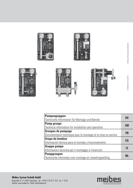
<strong>Pumpengruppen</strong><br />
<strong>Technische</strong> Information für Montage und Betrieb<br />
Pump groups<br />
Technical information for installation and operation<br />
Groupes de pompage<br />
Documentation technique pour le montage et la mise en service<br />
Grupo de bombas<br />
Información técnica para el montaje y funcionamiento<br />
Gruppo pompa<br />
Informazioni tecniche per il montaggio e l‘esercizio<br />
Pompgroepen<br />
<strong>Technische</strong> informatie voor montage en inwerkingstelling<br />
PR 24002.142 07-02-2013 <strong>Technische</strong> Änderungen vorbehalten<br />
DE<br />
GB<br />
FR<br />
ES<br />
IT<br />
NL
Abb./Fig. 1<br />
Abb./Fig. 2<br />
Abb./Fig. 3<br />
Abb./Fig. 4 A<br />
Abb./Fig. 4.1<br />
2<br />
1<br />
B C<br />
A B<br />
Abb./Fig. 4.2<br />
Abb./Fig. 5<br />
Abb./Fig. 5.1<br />
Abb./Fig. 5.2<br />
Abb./Fig. 6<br />
A<br />
A<br />
M<br />
~<br />
1 2 3<br />
B<br />
C<br />
D<br />
A B<br />
B<br />
G<br />
E<br />
F<br />
HxBxT 93x82x92,5<br />
C<br />
L1 N L1
Abb./Fig. 7<br />
Abb./Fig. 7.1<br />
Abb./Fig. 7.2<br />
Abb./Fig. 8<br />
Abb./Fig. 9<br />
Abb./Fig. 10<br />
Abb./Fig. 11.1<br />
Abb./Fig. 11.2<br />
Abb./Fig. 12<br />
Abb./Fig. 12.1<br />
Abb./Fig. 13<br />
Abb./Fig. 11<br />
93<br />
A<br />
39,50<br />
79<br />
B<br />
C<br />
76<br />
83<br />
D
Abb./Fig. 14<br />
Abb./Fig. 14.1<br />
Abb./Fig. D1<br />
B<br />
Abb./Fig. D2<br />
B<br />
A<br />
C<br />
A<br />
C<br />
3/4 "<br />
1 "<br />
1 1/4 "<br />
3/4 "<br />
1 "<br />
1 1/4 "<br />
Abb./Fig. D3<br />
B<br />
Abb./Fig. D3.1<br />
B<br />
Abb./Fig. D4<br />
B<br />
Abb./Fig. D5<br />
B<br />
A<br />
C<br />
A<br />
C<br />
A<br />
C<br />
A<br />
C<br />
Wü-Plattenzahl 20<br />
Wü-Plattenzahl 30<br />
Wü-Plattenzahl 36<br />
Wü-Plattenzahl 20<br />
Wü-Plattenzahl 30<br />
Wü-Plattenzahl 36
Inhalt<br />
1. <strong>Pumpengruppen</strong> UK (ungemischter Kreis) 2<br />
2. <strong>Pumpengruppen</strong> MK (gemischter Kreis) 2<br />
3. Montage 2<br />
3.1 Zählereinbau 2<br />
4. Einsatz von Hocheffizienzpumpen 3<br />
5. Mischer 3<br />
6. Stellmotor 3<br />
7. Thermometerwechsel 4<br />
8. Schwerkraftbremse 4<br />
9. Service-Hinweise zur sach- und 4<br />
funktionsgerechten<br />
Inbetriebnahme der Heizanlage<br />
10. Trennsysteme 5<br />
(für Anschluss am geregelten Heizkreis)<br />
11. Konstantwertregelset 5<br />
11.1 Konstantwertregelset 5<br />
(thermostatisch geregelt)<br />
11.1.1 Konstantwertregelset <strong>Technische</strong> Daten 6<br />
11.1.2 Einsatzbeispiel 6<br />
11.1.3 Thermostatkopf-Montage 6<br />
11.1.4 Einstellen der Temperatur des 6<br />
geregelten Heizkreises<br />
11.1.5 Sicherheitstemperaturbegrenzung 7<br />
(Anlegethermostat)<br />
11.2 Konstantwertregelset 7<br />
(elektronisch geregelt)<br />
11.2.1 Stellantrieb mit intergrierter 7<br />
Temperaturregelung<br />
12. Rücklaufanhebung 8<br />
12.1 Rücklaufanhebung DN 25 (1”) 8<br />
(thermostatisch geregelt)<br />
12.1.1 Rücklaufanhebung <strong>Technische</strong> Daten 8<br />
12.1.2 Einsatzbeispiel 8<br />
12.1.3 Einstellen der Rücklauftemperatur 8<br />
12.2 Rücklaufanhebung MK DN 25 (1”) 8<br />
(elektronisch geregelt)<br />
Sicherheitshinweise<br />
Sicherheitshinweise<br />
Bitte befolgen Sie diese Sicherheitshinweise genau,<br />
um Gefahren und Schäden für Menschen und Sachwerte<br />
auszuschließen. Die Montage, Erstinbetriebnahme,<br />
Inspektion, Wartung und Istandsetzung müssen<br />
von einer zugelassenen Fachfirma ausgeführt werden. Machen<br />
Sie sich vor Arbeitsbeginn mit allen Teilen und deren Handhabung<br />
vertraut. Beachten Sie die gültigen Unfallverhütungsvorschriften,<br />
Umweltvorschriften und gesetzlichen Regeln für die Montage, Installation<br />
und den Betrieb. Des weiteren die relevanten einschlägigen<br />
Richtlinien der DIN, EN, DVGW, VDI und VDE sowie alle aktuellen<br />
relevanten länderspezifischen Normen, Gesetze und Richtlinien.<br />
Arbeiten an der Anlage:<br />
Anlage spannungsfrei schalten und auf Spannungsfreiheit kontrollieren<br />
(z.B. an der seperaten Sicherung oder einem Hauptschalter).<br />
Anlage gegen Wiedereinschalten sichern.<br />
(Bei Brennstoff Gas dem Gasabsperrhahn schließen und gegen unbeabsichtigtes<br />
Öffnen sichern). Instandsetzungsarbeiten an Bauteilen<br />
mit Sicherheitstechnischer Funktion sind unzulässig.<br />
Der Montageort muss trocken und frostsicher sein. Gefährdungen<br />
durch angrenzende Bauteile sind zu vermeiden. Der freie Zugang<br />
muss sichergestellt sein.<br />
Die in der nachfolgenden Anleitung benannten Bauteile sind für den Einsatz in<br />
Heizungsanalagen nach DIN EN 12828 bestimmt.<br />
- Vor Gebrauch Monteageanleitung lesen<br />
- Schnittgefahr<br />
- Quetschgefahr<br />
- Gefahr erhöhter Temperatur<br />
- Gefahr elektrischer Spannung<br />
- Sturzgefahr bei der Montage<br />
1<br />
DE
2<br />
1. <strong>Pumpengruppen</strong> UK (ungemischter Kreis)<br />
<strong>Technische</strong> Daten<br />
DN: 20 25 32<br />
Oberer Anschluss: G 3/4“ IG G 1“ IG G 1 1/4“ IG<br />
Unterer Anschluss: G 1 1/2“ AG (flachdichtend)<br />
Pumpe: siehe Artikelnummer<br />
Achsabstand: 125 mm<br />
Bauteile aus: Stahl, Messing, EPP-Isolierung<br />
Abmessung: ca. H 420 x B 250 x T 255 mm<br />
Dichtmaterialien: PTFE, asbestfreie Faserdichtung, EPDM<br />
Temperaturanzeige: 0 bis 120°C<br />
Einsatztemperatur: bis 110°C<br />
Betriebsdruck: PN 6<br />
kVs – Wert: 8,5 9,7 11<br />
2. <strong>Pumpengruppen</strong> MK (gemischter Kreis)<br />
<strong>Technische</strong> Daten<br />
DN: 20 25 32<br />
Oberer Anschluss: G 3/4“ IG G 1“ IG G 1 1/4“ IG<br />
Unterer Anschluss: G 1 1/2“ AG (flachdichtend)<br />
Pumpe: siehe Artikelnummer<br />
Achsabstand: 125 mm<br />
Bauteile aus: Stahl, Messing, EPP-Isolierung<br />
Abmessung: ca. H 420 x B 250 x T 255 mm<br />
Dichtmaterialien: PTFE, asbestfreie Faserdichtung, EPDM<br />
Temperaturanzeige: 0 bis 120°C<br />
Einsatztemperatur: bis 110°C<br />
Betriebsdruck: PN 6<br />
kVs – Wert: 6 6,2 6,4<br />
3. Montage<br />
1. Pumpengruppe mit Isolierung an vorhandene Verrohrung anbringen.<br />
2. Befestigung handfest anziehen.<br />
3. Untere Seiten und Mitte anzeichnen. Anschließend Kompaktverteiler mit ISO wieder entfernen.<br />
4. Wand nach Markierung bohren und Dübel einsetzen.<br />
5. Unterschale der Isolierung mit mitgelieferten Schrauben an der Wand befestigen. siehe Abb. 3<br />
3.1 Zählereinbau<br />
<strong>Pumpengruppen</strong> UK, MK sind auch als Variante mit Zählereinbaustrecke (UK-Z, MK-Z) verfügbar.<br />
Für Zählermontage das Teloskopstück tauschen und Fühlermuffe 1/2“ verwenden. Bitte Einbauanleitung des Zählers beachten.<br />
Passmaß: 3/4“ 90-110 mm<br />
1“ 90-130 mm siehe Abb. 8<br />
siehe Abb. 1 und Diagramm Abb. D1<br />
Abb. D1 A Volumenstrom-Druckverlust-Diagramm<br />
<strong>Pumpengruppen</strong> UK<br />
B Druckverlust (bar)<br />
C Volumenstrom (l/h)<br />
siehe Abb. 2 und Diagramm Abb. D2<br />
Abb. D2 A Volumenstrom-Druckverlust-Diagramm<br />
<strong>Pumpengruppen</strong> MK mit<br />
3-Wege-T-Mischer<br />
B Druckverlust (bar)<br />
C Volumenstrom (l/h)
4. Einsatz von Hocheffizienzpumpen<br />
Meibes <strong>Pumpengruppen</strong> werden innerhalb der EU mit Hocheffizienzpumpen ausgestattet. Für deren Einsatz gelten die vom Pumpenhersteller<br />
geforderten Montage- und Betriebsrichtlinien.<br />
Fabrikat WILO:<br />
Typ: Yonos PICO, Stratos PICO/ Stratos PARA<br />
Max. Vorlauf-/Medientemperatur: 85°C<br />
Max. Umgebungs-/Raumtemperatur: 30°C<br />
5. Mischer<br />
Die Lage des Bypasses geht aus der Abbildung hervor. Am Bypass lässt sich die Vorlauf-Temperatur durch Beimengung von Rücklaufwasser<br />
absenken. Die Einstellung des Bypasses ist stufenlos möglich. Dazu muss die Sicherheitsschraube (1) ca. 1 mm gelöst werden. Bei geöffnetem<br />
Bypass steht der Schlitz der Einstellschraube (2) parallel zur Kante des Bypasskanals. Bei geschlossenem Bypass steht der Schlitz im rechten<br />
Winkel zur Kante des Bypasskanals.<br />
Bypass-Einstellung siehe Abb. 4, 4.1 und 4.2<br />
Abb. 4 A Kante Bypasskanal<br />
B Bypass in Stellung ZU<br />
C Bypass in Stellung AUF<br />
6. Stellmotor<br />
Stellmotor inkl. Anbausatz<br />
mit 2 m Kabel verdrahtet für direkten Aufbau auf den Mischer mit Not-Handbetrieb und sichtbarer Stellungsanzeige.<br />
Für T-Mischer (Auf-Zu-Antrieb)<br />
3 Punkt Ansteuerung<br />
Drehwinkel elektrisch auf 90° begrenzt<br />
Hinweis: Der Stellmotor muss ausgerichtet auf den Mischer gesteckt und die Verschraubung handfest angezogen werden.<br />
Ausschreibungstext/Artikelbeschreibung<br />
Abb. 4.1 A Vorlauf links<br />
B Vorlauf rechts<br />
Stellmotor mit Not-Handbetriebmöglichkeit inkl. 2 m Anschlusskabel und Anbausatz für Mischer der <strong>Pumpengruppen</strong>.<br />
Hinweis: Bitte beachten Sie die Montageanleitung, die dem Stellbetrieb beiliegt.<br />
Fabrikat GRUNDFOS:<br />
Typ: Alpha 2, Alpha 2L<br />
Max. Vorlauf-/Medientemperatur: 80°C<br />
Max. Umgebungs-/Raumtemperatur: 27°C<br />
Besonderheiten: Pumpenstecker in Winkelform verwenden<br />
Abb. 4.2 A Mischer „offen“ voller Zulauf kesselseitig kein Beimischung rücklaufseitig<br />
B Bypass (in Stellung geschlossen)<br />
C Klemmschraube für Bypass<br />
D Abflachung am Wellenende in dieser Position<br />
E Schließelement<br />
F Zugehörige Griffstellung<br />
G Mischer „geschlossen“ voller Zulauf rücklaufseitig kein Zulauf kesselseitig<br />
3<br />
DE
4<br />
6. Stellmotor<br />
<strong>Technische</strong> Daten<br />
Elektrischer Anschluß: ~50 Hz/230 V<br />
Leistungsaufnahme: 2,5 W<br />
Drehmoment: 6 Nm<br />
Laufzeit: 140 s/90°<br />
Anschlußleitung: 3 x 0,5 mm 2<br />
siehe Abb. 5<br />
Elektr. Anschlussbild siehe Abb. 5.1 A braun B blau C weiß<br />
Not-Handbetrieb<br />
Handbetrieb Umschaltung mittels Drehknopf am Gehäuse<br />
siehe Abb. 5.2 A Handbetrieb B Automatikbetrieb<br />
Hinweis: Bitte die Bedienungsanleitung des Stellmotors beachten.<br />
7. Thermometerwechsel<br />
Die Thermometer sind nur eingesteckt und lassen sich einfach durch Herausziehen tauschen.<br />
Es sollte beachtet werden, dass ein entnommenes Thermometer durch ein gleichartiges ersetzt wird.<br />
Bitte auf die farbliche Kennzeichnung achten. (rote Schrift = VL; blaue Schrift = RL)<br />
siehe Abb. 6<br />
8. Schwerkraftbremse<br />
Die in unserem System verwendeten Schwerkraftbremsen (SB) oder/und Rückflussverhinderer (RV) sind extra gekennzeichnet. Sie sind in den<br />
Kugelhähnen integriert. Am Drehgriff ist die Kennzeichnung „SB” angebracht. Durch Verstellen des Drehgriffes um ca. 45° zur „Anschlagstellung”<br />
kann die SB manuell geöffnet werden.<br />
siehe Abb. 7, 7.1 und 7.2<br />
9. Service-Hinweise zur sach- und funktionsgerechten<br />
Inbetriebnahme der Heizanlage<br />
Achtung!<br />
Nach dem Befüllen und der anschließenden Druck- und Dichtheitsprüfung des Kessels bzw. Speichers darf die Verbindung zum nachfolgenden<br />
Rohrsystem nur durch die Betätigung (Öffnen) des Kugelhahns im Rücklauf erfolgen, da durch den Überdruck (Prüfdruck) im Kessel/Speicher<br />
ein Druckstoß entstehen kann. Würde der Kugelhahn im Vorlauf zuerst geöffnet werden, könnte dieser Druckstoß eine Beschädigung der<br />
Schwerkraftbremse im Rücklauf zur Folge haben.<br />
siehe Abb. 8<br />
Artikel-Nr.: 66341<br />
Schutzklasse: II<br />
Schutzart: IP40<br />
Umgebungstemperatur: -10 bis +50° C<br />
Gewicht: 0,4 kg
10. Trennsystem (für Anschluß am geregelten Heizkreis)<br />
Eine Übertemperaturabschaltung für Fußbodenheizung ist in der Baugruppe nicht integriert. Sie sollte bauseits angebracht werden. Sicherheitsgruppe<br />
ist integriert mit Sicherheitsventil 3 bar.<br />
<strong>Technische</strong> Daten<br />
Trennsystem:<br />
Max. Leistung<br />
45811.21 45811.31 45811.37<br />
(bei Sekundär 35°C/45°C und<br />
Primär 70°C/50°C):<br />
22 kW 25 kW 30 kW<br />
Max. Druck: 3 bar 3 bar 3 bar<br />
Maximale Temperatur: 110°C 110°C 110°C<br />
Bauhöhe mit Isolierung: 420 mm 420 mm 420 mm<br />
Breite mit Isolierung: 250 mm 250 mm 250 mm<br />
Tiefe mit Isolierung: 255 mm 255 mm 255 mm<br />
Werkstoff der Isolierung: EPP EPP EPP<br />
Achsabstand: 125 mm 125 mm 125 mm<br />
Oberer und unterer Anschluss: 1“ IG 1“ IG 1“ IG<br />
Wärmetauscher Plattenanzahl: 20 30 36<br />
Max. Druckverlust: 20 kPa 20 kPa 20 kPa<br />
Wärmetauscher: Plattenmaterial W-Nr. 1-4401Lötmaterial<br />
Kupfer (99,9%)<br />
11. Konstantwertregelset<br />
11.1 Konstantwertregelset thermostatisch geregelt<br />
Das Konstantwertregelset ist ein Heizkreis mit einem elektrisch geregelten Mischer für die Fußbodenheizung. Die Vorlauftemperatur lässt sich<br />
durch ein Thermostatventil am 3-Wege-T-Mischer einstellen. Durch den einstellbaren Bypass wird Wasser aus dem Rücklauf in den Vorlauf<br />
beigemischt und hierdurch die umlaufende Wassermenge im Heizkreis erhöht. Zur Verbesserung bzw. Glättung des Regelverhaltes kann der<br />
Mischerbypass (speziell bei Solltemperaturen von 35...45°C und Vorlauftemperaturen von ca. 75°C) geöffnet werden. Bei Bedarf bzw. bei<br />
Anbindung eines Flächenheizkreises ist der beigelegte Temperaturregler zur Maximaltemperaturbegrenzung min. 1m hinter dem Mischer und<br />
der Heizkreispumpe in Fließrichtung an einem gut wärmeleitenden Rohrstück fachgerecht anzubringen und elektrisch anzuklemmen. Durch ein<br />
Anlegethermostat wird eine Sicherheitstemperaturbegrenzung ermöglicht. Bei Übersteigen der Vorlauftemperatur wird die Pumpe abgeschaltet.<br />
Seitenwechsel von Vor- und Rücklauf ist nicht möglich! Der Einbau des Konstantwertregelsets in einem System mit kesselseitigem<br />
Vordruck wird nicht empfohlen.<br />
siehe Abb. 10<br />
siehe Abb. 9 und Diagramm Abb. D3 und D3.1<br />
Abb. D3 A Volumenstrom-Druckverlust-Diagramm<br />
Trennsystem Sekundärseite<br />
B Druckverlust (bar)<br />
C Volumenstrom (l/h)<br />
Abb. D3.1 A Volumenstrom-Druckverlust-Diagramm<br />
Trennsystem Primärseite<br />
(Wärmeübertrager)<br />
B Druckverlust (bar)<br />
C Volumenstrom (l/h)<br />
5<br />
DE
6<br />
11. Konstantwertregelset<br />
11.1.1 Konstantwertregelset <strong>Technische</strong> Daten<br />
<strong>Technische</strong> Daten<br />
DN: 25<br />
Oberer Anschluss: 1“ IG<br />
Unterer Anschluss: G 1 1/2“ AG (flachdichtend)<br />
Pumpe: siehe Artikelnummer<br />
Achsabstand: 125 mm<br />
Bauteile aus: Messing, EPP-Isolierung<br />
Abmessung: ca. H 500 x B 250 x T 255 mm<br />
Dichtmaterialien: PTFE, asbestfreie Faserdichtung, EPDM<br />
Temperaturanzeige: 0 bis 120°C<br />
Einsatztemperatur: 110°C/ im Mischkreis nur 60°C !<br />
Betriebsdruck: PN 6<br />
Art.-Nr.: 45890<br />
siehe Diagramm Abb. D4<br />
A Volumenstrom-Druckverlust-Diagramm Konstantwertregelset<br />
B Druckverlust (bar)<br />
C Volumenstrom (l/h)<br />
11.1.2 Einsatzbeispiel<br />
siehe Abb. 11 A Fußbodenheizung B Sekundärkreis C Primärkreis D Kessel/Therme<br />
11.1.3 Thermostatkopf-Montage<br />
Thermostatkopf bzw. Baugruppe vor Montage auf Raumtemperatur (ca.18°C) temperieren.<br />
Montage des Thermostatkopfes auf das Ventil<br />
1. Zur besseren Montage des Thermostatkopfes die Thermostatkopfeinstellung auf Stufe 5 stellen.<br />
2. Beim Aufstecken des Kopfes auf das Unterteil die Position des seitlichen Arretierungsstiftes beachten.<br />
3. Überwurfmutter des Kopfes handfest anziehen.<br />
4. Darauf achten, dass sich der Thermostatkopf nach der Montage leichtgängig verstellen lässt.<br />
siehe Abb. 11.1<br />
11.1.4 Einstellen der Temperatur des geregelten Heizkreises<br />
Thermostatkopfeinstellung<br />
Der Temperatureinstellbereich beträgt 20°C - 50°C. Die gewünschte Temperatur des geregelten Heizkreises ist am Thermostatkopf der Baugruppe<br />
einzustellen und am Thermometer im Vorlauf (rot) abzulesen.<br />
Hinweis: Die Temperatur im geregelten Heizkreis stellt sich nicht sofort nach Verstellen des Thermostatkopfes ein, so dass die Temperatur<br />
nach angemessener Laufzeit des geregelten Heizkreises abzulesen ist.<br />
Der Thermostatkopf ist mit einer Stellungsarretierung für eine zusätzliche Temperaturbegrenzung versehen.<br />
Vorlauftemperatur des<br />
gemischten Heizkreises<br />
in °C<br />
* ca. 25°<br />
1 ca. 30°<br />
2 ca. 35°<br />
3 ca. 40°<br />
4 ca. 45°<br />
5 ca. 50°
11. Konstantwertregelset<br />
11.1.5 Sicherheitstemperaturbegrenzung (Anlegethermostat)<br />
1. Anlegethermostat mit Hilfe des Spannbandes am Rohr befestigen,<br />
so dass ein Kontakt für Wärmeübergang gewährleistet ist.<br />
2. Nach dem Lösen der Schrauben den Deckel abnehmen.<br />
3. Elektrischen Anschluss gemäß Schaltschema vornehmen.<br />
4. Kabel an der Zugentlastung fixieren.<br />
5. Deckel anbringen und mit Schrauben befestigen.<br />
siehe Abb. 11.2<br />
11.2 Konstantwertregelset (elektronisch geregelt)<br />
<strong>Technische</strong> Daten<br />
DN: 25<br />
Oberer Anschluss: 1“ IG<br />
Unterer Anschluss: G 1 1/2“ AG (flachdichtend)<br />
Pumpe: siehe Artikelnummer<br />
Achsabstand: 125 mm<br />
Bauteile aus: Messing, EPP-Isolierung<br />
Abmessung: ca. H 500 x B 250 x T 255 mm<br />
Dichtmaterialien: PTFE, asbestfreie Faserdichtung, EPDM<br />
Temperaturanzeige: 0° bis 120°C<br />
Einsatzbereich (max.): 110°C / im Mischkreis 60°C<br />
Betriebsdruck: PN 6<br />
11.2.1 Stellantrieb mit integrierter Temperaturreglung<br />
<strong>Technische</strong> Daten<br />
Nennspannung: AC 230 V 50 Hz<br />
Leistungsverbrauch: ca. 3,3 W<br />
Drehsinn: wählbar über interne Verdrahtung<br />
Handbetrieb: Drehknopf am Gehäuse<br />
Drehmoment: 10 Nm<br />
Drehwinkel: 90°<br />
Laufzeit: 150 s<br />
Stellungsanzeige: LED’s<br />
Schutzklasse: II (schutzisoliert, ohne Schutzleiter)<br />
Schutzart: IP 50<br />
Bitte beachten Sie die Montage- und Bedienungsanleitung des Stellantriebes.<br />
<strong>Technische</strong> Daten<br />
Einstellbereich: 30–90°C<br />
Schaltleistung: 16 (3) A, 250 V<br />
Schaltdifferenz: 5–10 k, einstellbar<br />
Schutzart: IP 30<br />
Abmessung: 114 x 46,5 x 46,5 mm<br />
Prüfklasse: II (100.000) VDE-geprüft<br />
Pumpe siehe Art.-Nr.<br />
siehe Abb. 12<br />
Art.-Nr. 66341.32 (Regelbereich 20°C - 80°C)<br />
Für T-Mischer<br />
Auf-Stop-Zu-Antrieb (AC 230 V)<br />
3-Punkt-Ansteuerung<br />
Anwendung:<br />
Der Antrieb wird zur Motorisierung und Regelung der Meibes-<br />
Mischer in HLK-Systemen eingesetzt.<br />
Wirkungsweise:<br />
Die Ansteuerung erfolgt durch den integrierten<br />
Temperaturregler.<br />
siehe Abb. 12.1<br />
7<br />
DE
8<br />
12. Rücklaufanhebung<br />
12.1 Rücklaufanhebung DN 25 (1”) thermostatisch geregelt<br />
Die Rücklauftemperaturanhebung wird direkt nach dem Wärmeerzeuger montiert. In Abhängigkeit der Temperatur des Rücklaufs am Kesseleintritt<br />
wird über einen Mischervorlauf Wasser beigemischt. Der Wärmeerzeuger erreicht schneller seine Betriebstemperatur. Eine Taupunktunterschreitung<br />
bzw. Kondensation im Brennraum kann somit vermieden werden. Die Solltemperatur lässt sich über den Thermostat- bzw.<br />
elektrischen Regler am 3-Wege-T-Mischer einstellen. Die Höhe der minimalen Rücklauftemperatur ist abhängig vom Kesseltyp.<br />
siehe Abb. 13<br />
12.1.1 Rücklaufanhebung <strong>Technische</strong> Daten<br />
<strong>Technische</strong> Daten<br />
DN: 25<br />
Oberer Anschluss: HK-Anschluss 1 1/2“ IG<br />
Unterer Anschluss: Kessel-Anschl. 1“ IG (flachdichtend)<br />
Pumpe: siehe Artikelnummer<br />
Achsabstand: 125 mm<br />
Bauteile aus: Stahl, Messing, EPP-Isolierung<br />
Abmessung: ca. H 420 x B 250 x T 255 mm<br />
Dichtmaterialien: PTFE, asbestfreie Faserdichtung/ EPDM<br />
Temperaturanzeige: 0° bis 120°C<br />
Einsatztemperatur: max. 110°C<br />
Betriebsdruck: PN 6<br />
Art.-Nr.: 45841<br />
12.1.3 Einstellen der Rücklauftemperatur<br />
siehe Diagramm Abb. D5<br />
Abb. D5 A Volumenstrom-Druckverlust-Diagramm<br />
Rücklaufanhebung<br />
B Druckverlust (bar)<br />
C Volumenstrom (l/h)<br />
12.1.2 Einsatzbeispiel<br />
siehe Abb. 14 A Kessel/Therme<br />
Der Temperatureinstellbereich beträgt 40°C - 70°C. Die gewünschte Rücklauftemperatur ist am Thermostatkopf der Baugruppe einzustellen<br />
und am Thermometer im Rücklauf (blau) abzulesen.<br />
Hinweis: Die Rücklauftemperatur stellt sich nicht sofort nach Verstellen des Thermostatkopfes ein, so dass die Temperatur nach angemessener<br />
Laufzeit abzulesen ist.<br />
12.2 Rücklaufanhebung MK DN 25 (1”) (elektronisch geregelt)<br />
<strong>Technische</strong> Daten<br />
DN:<br />
25<br />
Oberer Anschluss/HK-Anschluss:<br />
Anschluss/HK-Anschluss: 1 1/2“ IG (flachdichtend)<br />
Unterer Unterer Anschluss/Kesselanschluss:<br />
Anschluss/Kesselanschluss:<br />
1“ IG<br />
Pumpe:<br />
siehe Artikelnummer<br />
Achsabstand:<br />
125 mm<br />
Bauteile aus:<br />
Stahl, Messing, EPP-Isolierung<br />
Abmessung:<br />
ca. H 420 x B 250 x T 255 mm<br />
Dichtmaterialien:<br />
PTFE, asbestfreie Faserdichtung/ EPDM<br />
Temperaturanzeige:<br />
0° bis 120°C<br />
Einsatzbereich:<br />
max. 110°C<br />
Betriebsdruck:<br />
PN 6<br />
Pumpe siehe Art.-Nr.<br />
siehe Abb. 14.1
Table of contents<br />
1. Pump groups UC (unmixed circuit) 10<br />
2. Pump groups MC (mixed circuit) 10<br />
3. Installation 10<br />
3.1 Installation of flowmeter 10<br />
4. Application of high-efficiency pumps 11<br />
5. Mixer 11<br />
6. Actuator 11<br />
7. Replacing the thermometer 12<br />
8. Gravity brake 12<br />
9. Instructions for the proper 12<br />
and functional operation of<br />
the heating system<br />
10. Split system 13<br />
(for connection to regulated heating circuits)<br />
11. Constant heat regulation set 13<br />
11.1 Constant heat regulation set 13<br />
(thermostatically controlled)<br />
11.1.1 Constant heat regulation set - technical data 14<br />
11.1.2 Example of use 14<br />
11.1.3 Assembly of the thermostatic head 14<br />
11.1.4 Setting the regulated heating 14<br />
circuit temperature<br />
11.1.5 High temperature limiting 15<br />
(clip-on thermostat)<br />
11.2 Constant heat regulation set 15<br />
(electronically controlled)<br />
11.2.1 Actuator with integrated 15<br />
temperature control<br />
12. Return flow heat regulation system 16<br />
12.1 Return flow heat regulation DN 25 (1”) 16<br />
(thermostatically controlled)<br />
12.1.1 Return flow heat regulation - technical data 16<br />
12.1.2 Example of use 16<br />
12.1.3 Setting the return flow temperature 16<br />
12.2 Return flow heat regulation MC DN 25 (1”) 16<br />
(electronically controlled)<br />
Safety guidelines<br />
Safety guidelines<br />
Please follow these safety guidelines carefully in order<br />
to prevent danger or damage to persons or property.<br />
Assembling, commissioning, inspection, maintenance<br />
and repair must be carried out by a registered specialist<br />
company.<br />
Before starting work make yourself familiar yourself with all components<br />
and their functions. Follow the current accident prevention<br />
directives, environmental directives and legal regulations for<br />
assembly, installation and operation. Furthermore, make also sure<br />
you know the relevant applicable DIN, EN, DVGW, VDI and VDE<br />
standards as well as all current relevant country-specific standards,<br />
laws and guidelines..<br />
Operating the System:<br />
Disconnect the system from the power supply and ensure that it is<br />
safely isolated from the power supply (e.g. at the separate fuse or a<br />
master switch).<br />
Secure the system against being switched back on.<br />
(In the case of fuel gas, close the gas isolating valve and secure<br />
against accidental opening). Repair work on components with safetyrelated<br />
functions are not permitted.<br />
The place of installation must be dry and frost-free. Avoid danger due<br />
to adjacent components. Provide for free access.<br />
The components listed in the following instructions are intended for use<br />
in heating systems in accordance with DIN EN 12828.<br />
- Read the assembly instructions before<br />
use<br />
- Risk of being cut<br />
- Risk of being crushed<br />
- High temperature hazard<br />
- Electric voltage hazard<br />
- Risk of falling during installation<br />
9<br />
GB
10<br />
1. Pump groups UC (unmixed circuit)<br />
Technichal data<br />
DN: 20 25 32<br />
Top connection: 3/4“ FI 1“ FI 1 1/4“ FI<br />
Bottom connection: 1 1/2“ MI (flat-sealing)<br />
Pump: see ref. number<br />
Axial separation: 125 mm<br />
Components of: Steel, Brass, EPP insulation<br />
Dimensions: ca. H 420 x W 250 x D 255 mm<br />
Sealing materials: PTFE asbestos-free fibre washer<br />
Temperature range: 0° up to 120°C<br />
Operating temperature: up to 110°C<br />
Operating pressure: PN 6<br />
kVs values: 8.5 9.7 11<br />
2. Pump groups MC (mixed circuit)<br />
Technichal data<br />
DN: 20 25 32<br />
Top connection: 3/4“ FI 1“ FI 1 1/4“ FI<br />
Bottom connection: 1 1/2“ MI (flat-sealing)<br />
Pump: see ref. number<br />
Axial separation: 125 mm<br />
Components of: Steel, Brass, EPP insulation<br />
Dimensions: ca. H 420 x W 250 x D 255 mm<br />
Sealing materials: PTFE asbestos-free fibre washer<br />
Temperature display: 0° up to 120°C<br />
Operating temperature: up to 110°C<br />
Operating Pressure: PN 6<br />
kVs values: 6 6.2 6.4<br />
3. Installation<br />
1. Connect the pump group, including the insulation, to the existing pipe installation.<br />
2. Tighten the fixations by hand.<br />
3. Mark the bottom and the middle of the case. Subsequently remove the compact distributor again, according to ISO.<br />
4. Drill holes into the wall according to the markings and insert wall plugs.<br />
5. Mount the bottom case by using the screws and washers supplied. see Fig. 3<br />
3.1 Installation of flowmeter<br />
The pump groups UK, MK are also available as variants with flow meter inserts (UK-Z, MK-Z).To install the flowmeter, replace the telescope<br />
piece and use the probe sleeve 1/2“. Please follow the installation instructions for the flowmeter.<br />
Dimension: 3/4“ 90-110 mm<br />
1“ 90-130 mm See Fig. 8<br />
see Fig. 1 and Diagram Fig. D1<br />
Fig. D1 A Volumetric flow - pressure loss<br />
diagram Pump group UC<br />
B Pressure loss (bar)<br />
C Volumetric flow (l/h)<br />
see Fig. 2 and Diagram Fig. D2<br />
Fig. D2 A Volumetric flow - pressure loss<br />
diagram Pump group MC<br />
with 3-way T-mixer<br />
B Pressure loss (bar)<br />
C Volumetric flow (l/h)
4. Application of high-efficiency pumps<br />
Within the EU, Meibes pump groups are equipped with high-efficiency pumps. To use them observe the assembly and operating instructions<br />
issued by the pump manufacturer.<br />
WILO brand:<br />
Type: Yonos PICO, Stratos PICO/ Stratos PARA<br />
Max. flow/process temperature: 85°C<br />
Max. ambient/room temperature: 30°C<br />
5. Mixer<br />
The position of the bypass is shown in the illustration. The bypass can be used to reduce the flow temperature through the addition of return<br />
flow water. The bypass adjustment is continuously variable. To adjust the temperature loosen the securing screw (1) by approx. 1mm. and turn<br />
the screw. The bypass is fully opened when the slot of the screw (2) is parallel to the edge of the bypass duct. When fully closed, the slot is at a<br />
right angle to the bypass duct.<br />
Bypass adjustment - see Fig. 4, 4.1 and 4.2<br />
Fig. 4 A Edge of the bypass duct<br />
B Bypass in closed position<br />
C Bypass in open position<br />
6. Actuator<br />
Fig. 4.1 A FLow left<br />
B Flow right<br />
Actuator incl. mounting set<br />
with 2 m cable wired for direct installation on the mixer with manual emergency operation and visible position indicator.<br />
For T-type mixer (Open-Close drive mechanism)<br />
3-point control<br />
Rotary angle electrically limited to 90°<br />
Note: Plug the actuator on the mixer in an aligned way and hand-tighten the screwed connection.<br />
Text of tender specification/Item description<br />
Actuator with manual operation possibility in an emergency incl. 2 m connecting cable and mounting set for the mixing unit of the pump<br />
groups.<br />
Note: Please observe the installation instructions attached to the actuator.<br />
GRUNDFOS brand:<br />
Type: Alpha 2, Alpha 2L<br />
Max. flow/operating temperature: 80°C<br />
Max. ambient/room temperature: 27°C<br />
Special features: Use an angle pump connector.<br />
Fig. 4.2 A Mixer closed (full flow on the boiler side; no mixing on return side)<br />
B Bypass (closed in position)<br />
C Clamp screw for bypass<br />
D Flattening of the shaft end in this position<br />
E Closing element<br />
F Matching handle position<br />
G Mixer opened (full flow on return flow side; no flow on boiler side)<br />
11<br />
GB
12<br />
6. Actuator<br />
Technical Data<br />
Electrical connection: ~50 Hz/230 V<br />
Power consumption: 2,5 W<br />
Torque: 6 Nm<br />
Run time: 140 s/90°<br />
Connection cable: 3 x 0,5 mm 2<br />
see Fig. 5<br />
Wiring diagram see Fig. 5.1 A brown B blue C white<br />
Manual emergency operation<br />
Manual operation Change-over by rotary knob on housing<br />
see Fig. 5.2 A Manual operation B Automatic operation<br />
Note: Please observe the Operating Instructions of the actuator.<br />
7. Replacing the thermometer<br />
The thermometer is pushed into a pocket and can easily be pulled out for replacement.<br />
Ensure that the thermometer is replaced by a similar thermometer with the same colour coding.<br />
(Red dial = flow; Blue dial = Return)<br />
see Fig. 6<br />
8. Gravity brake<br />
The gravity brake and/or check valves used in our systems are specifically marked. They are integrated into the ball valve. The handle is<br />
labelled with „SB”. The gravity brake can be de-activated by turning the handle approx. 45° to the stop position - “Anschlagstellung”.<br />
see Fig. 7. and 7.2<br />
9. Instructions for the proper and functional operation of the<br />
heating system<br />
Note!<br />
After filling and following pressure and leak test of the vessel or the accumulator, the connection to the subsequent piping system may only be<br />
established by the actuation (opening) of the ball valve in the return circuit because the overpressure (test pressure) in the vessel/acculumator<br />
can cause a pressure surge. If the ball valve in the forward flow is opened first, this pressure surge could damage the gravity brake in the<br />
return circuit.<br />
see Fig. 8<br />
Item-No: 66341<br />
Protection rating: II<br />
Protection class: IP40<br />
Ambient temperature: -10 to +50° C<br />
Weight: 0,4 kg
10. Split system (for connection to regulated heating circuits)<br />
A high-temperature switch-off function for under-floor heating is not integrated into the unit. This has to be fitted by a specialist installer<br />
when the system is being installed. A safety group with a 3 bar safety valve is integrated.<br />
Technical data<br />
Split system type:<br />
Max. capacity<br />
45811.21 45811.31 45811.37<br />
(secondary circuit 35°C/45°C<br />
and primary circuit 70°C/50°C):<br />
22 kW 25 kW 30 kW<br />
Maximum pressure: 3 bar 3 bar 3 bar<br />
Maximum temperature: 110°C 110°C 110°C<br />
Installation height with insulation:<br />
420 mm 420 mm 420 mm<br />
Width with insulation: 250 mm 250 mm 250 mm<br />
Depth with insulation: 255 mm 255 mm 255 mm<br />
Insulation material: EPP EPP EPP<br />
Axial separation: 125 mm 125 mm 125 mm<br />
Top and bottom connection: 1“ IG 1“ IG 1“ IG<br />
No. of heat exchanger plates: 20 30 36<br />
Max. pressure loss: 20 kPa 20 kPa 20 kPa<br />
Heat exchanger: Plate material W-No. 14401, copper<br />
soldering material (99,9%)<br />
11. Constant heat regulation set<br />
11.1 Thermostatically controlled heat regulation set<br />
The constant heat regulation set is an electrically controlled mixing valve for under floor heating. The flow temperature can be adjusted at<br />
the 3-way T-mixer. Water from the return is mixed into the flow through the adjustable bypass, and the quantity of water circulating in the<br />
heating circuit is increased as a result. A clip-on thermostat allows for a temperature delimitation safeguard to be implemented. In the event<br />
of the flow temperature being exceeded the pump is switched off. Constant temperature control set, regulated by thermostat Complete with<br />
circulating pump (EL 180 mm) with 2 m connection cable, two 3-way ball valves (one with manually-positioned gravity brake), two contact<br />
thermometers, 3- way T-mixer, thermostat head with remote sensor (adjustment range 25-50 ºC), clip-on thermostat, wall mount, return pipe,<br />
EPP insulation, all completely assembled.<br />
see Fig. 10<br />
see Fig. 9 and Diagram Fig. D3 and D3.1<br />
Fig. D3 A Volumetric flow - pressure loss diagram<br />
Split system secondary side<br />
B Pressure loss (bar)<br />
C Volumetric flow (l/h)<br />
Fig. D3.1 A Volumetric flow - pressure loss diagram<br />
Split system primary side<br />
B Pressure loss (bar)<br />
C Volumetric flow (l/h)<br />
13<br />
GB
14<br />
11. Constant heat regulation set<br />
11.1.1 Constant heat regulation set - technical data<br />
Technical data<br />
DN: 25<br />
Top connection: 1“ FI<br />
Bottom connection: 1 1/2“ MI (flat-sealing)<br />
Pump: see ref. number<br />
Axial separation: 125 mm<br />
Components of: Steel, Brass, EPP insulation<br />
Dimensions: ca. H 500 x W 250 x D 255 mm<br />
Sealing materials: PTFE, asbestos-free fibre washer<br />
Temperature display: 0° up to 120°C<br />
Operating temperature: 110°C/ in mixer circuit only 60 °C!<br />
Operating pressure: PN 6<br />
Ref. number: 45890<br />
see Diagram Fig. D4<br />
A Volumetric flow - pressure loss diagram - constant heat regulation set<br />
B Pressure loss (bar)<br />
C Volumetric flow (l/h)<br />
11.1.2 Example of use<br />
see Fig. 11 A Under-floor heating B Secondary circuit C Primary circuit D Boiler/Heat source<br />
11.1.3 Assembly of the thermostatic head<br />
Allow the temperature of the thermostatic head or the component to stabilize to room temperature (approx. 18 °C).<br />
Assembly of the thermostatic head to the valve<br />
1. To ease installation of the thermostatic head set the thermostat setting at level 5.<br />
2. When plugging of the head on the lower part note the position of the lateral locking pin.<br />
3. Nut of the head hand tighten.<br />
4. Make sure that the thermostatic head can be adjusted easily after assembly.<br />
see Fig. 11.1<br />
11.1.4 Setting the temperature of the controlled heating circuit<br />
The temperature range is 20°C - 45°C. To adjust the temperature to the required temperature turn the thermostatic head of the component: a<br />
reading can be taken at the thermometer in flow (red). The changes can be taken from the thermometer in the flow (red).<br />
Note: The temperature does not change immediately after the thermostatic head has been adjusted, i.e. the temperature can be read on the<br />
regulated heating circuit after an appropriate runtime.<br />
The thermostatic head is equipped with an arrestor for an additonal temperature limitation.<br />
Setting of thermostatic<br />
head<br />
Flow temperature of the<br />
mixed heating circuit<br />
* ca. 25°<br />
1 ca. 30°<br />
2 ca. 35°<br />
3 ca. 40°<br />
4 ca. 45°<br />
5 ca. 50°
11. Constant heat regulation set<br />
11.1.5 High temperature limiter (clip-on thermostat)<br />
1. Use the strap to fit the clip-on thermostat to the pipe, to ensure a<br />
contact for heat conduction.<br />
2. Loosen the screws and remove the cover.<br />
3. Make the electrical connections according to the wiring diagram.<br />
4. Secure the cable with the cord grip.<br />
5. Cover and secure it with screws.<br />
see Fig. 11.2<br />
11.2 Constant heat regulation set (electronically controlled)<br />
Technical data<br />
DN: 25<br />
Top connection: 1“ FI<br />
Bottom connection: 1 1/2“ MI (flat face)<br />
Pump: see ref. number<br />
Axial separation: 125 mm<br />
Components of: Brass, EPP insulation<br />
Dimensions: ca. H 500 x W 250 x D 255 mm<br />
Sealing materials: PTFE, asbestos-free fibre sealing, EPDM<br />
Temperature display: 0° up to 120°C<br />
Usage range (max.): 110°C<br />
Operating pressure: PN 6<br />
11.2.1 Actuator with integrated temperature regulator<br />
Technical data<br />
Nominal voltage: AC 230 V 50 Hz<br />
Power consumption: ca. 3.3 W<br />
Direction of rotation: Selectable via internal wiring<br />
Manual operation: Rotary knob on housing<br />
Torque: 10 Nm<br />
Angle of rotation: 90°<br />
Run time: 150 s<br />
Position indicator: LED’s<br />
Protection rating: II (insulated, without conductor)<br />
Protection class: IP 50<br />
see Fig. 12<br />
ref. number 66341.32 (control range 20°C - 80°C)<br />
For T-mixer<br />
On stop-closed drive (AC 230 V)<br />
3-point control<br />
Application:<br />
The drive is used for the motorization and control of the<br />
Meibes mixers in HVAC systems.<br />
Mode of operation:<br />
Controlled by an integrated temperature controller.<br />
see Fig. 12.1<br />
Please pay attention to the installation and operating instructions of the actuator.<br />
Technical data<br />
Setting range: 30–90°C<br />
Switching capacity: 16 (3) A, 250 V<br />
Switching difference: 5–10 k, adjustable<br />
Protection category: IP 30<br />
Dimensions: 114 x 46.5 x 46.5 mm<br />
Test category: II (100.000) VDE-inspected<br />
Pump see item No.<br />
15<br />
GB
16<br />
12. Return temperature limiter system<br />
12.1 Return flow heat regulation system DN 25 (1”) thermostatically controlled<br />
The return flow heat regulation system is mounted beneath the manifold joint. Depending on the return temperature, the flow is mixed to the<br />
return. The result is a shorter heating-up time and it prevents the combustion chamber from condensation. The required return temperature<br />
can be set via the thermostat or the electrical regulator on the 3-way T- mixer. The minimum return temperature dependents on the type of<br />
boiler used.<br />
see Fig. 13<br />
12.1.1 Return temperature limiter system – technical data<br />
Technical data<br />
DN: 25<br />
Top connection: manifold connection 1 1/2“ FI<br />
Bottom connection: Boiler connection 1“ FI (flat-sealing)<br />
Pump: see ref. number<br />
Axial separation: 125 mm<br />
Components of: Steel, Brass, EPP insulation<br />
Dimensions: ca. H 420 x W 250 x D 255 mm<br />
Sealing materials: PTFE, fiber joint free of astbestos, EPDM<br />
Temperature display: 0° up to 120°C<br />
Operating temperature: up to 110°C<br />
Operating pressure: PN 6<br />
Ref. number: 45841<br />
12.1.3 Adjusting the return temperature<br />
The temperature range is 40°C - 70°C. The required temperature of the mixed circuit can be set at the top of the component’s thermostat and<br />
can be read from the thermometer in the return flow (blue).<br />
Note: The temperature does not change immediately after the thermostatic head has been adjusted, i.e. the temperature can be read on the<br />
regulated heating circuit after an appropriate runtime.<br />
12.2 Return flow heat regulator DN 25 (1”) (electronically controlled)<br />
Technical data<br />
DN:<br />
Upper/Hot Top/hot boiler boiler connection:<br />
Lower/boiler Bottom boiler connection:<br />
Pump:<br />
Axial separation:<br />
Components of:<br />
Dimensions:<br />
Sealing materials:<br />
Temperature display:<br />
Usage range:<br />
Operational pressure:<br />
25<br />
1 1/2“ FI (flat-sealing)<br />
1“ FI<br />
see ref. number<br />
125 mm<br />
Steel, Brass, EPP insulation<br />
ca. H 500 x W 250 x D 255 mm<br />
PTFE, asbestos-free fibre sealing, EPDM<br />
0° up to 120°C<br />
up to 110°C<br />
PN 6<br />
see Diagram Fig. D5<br />
Fig. D5 A Volumetric flow - pressure loss<br />
diagram – return flow heat<br />
regulation<br />
B Pressure loss (bar)<br />
C Volumetric flow (l/h)<br />
12.1.2 Example of use<br />
see Fig. 14 A Boiler/Heat source<br />
Pump see item No.<br />
see Fig. 14.1
Table des matières<br />
1. Groupes de pompage UK (circuit non mélangé) 18<br />
2. Groupes de pompage MK (circuit mélangé) 18<br />
3. Montage mural 18<br />
3.1 Compteur 18<br />
4. Utilisation de pompes à haute efficacité 19<br />
5. Mélangeur 19<br />
6. Servomoteur 19<br />
7. Changement de thermomètre 20<br />
8. Clapet anti-retour 20<br />
9. Consignes de service –pour une mise en 20<br />
service de l’installation de chauffage<br />
approprié et professionnelle<br />
10. Systèmes de séparation 21<br />
(pour raccordement à un circuit de<br />
chauffage régulé)<br />
11. Système de régulation constante de 21<br />
la température<br />
11.1 Système de régulation constante de 21<br />
la température (réglé par thermostat)<br />
11.1.1 Système de régulation constante de 22<br />
la température - Données techniques<br />
11.1.2 Exemple d’utilisation 22<br />
11.1.3 Montage tête thermostatique 22<br />
11.1.4 Réglage de la température du circuit 22<br />
de chauffage régulé<br />
11.1.5 Limitation de la température de 23<br />
sécurité (thermostat à poser)<br />
11.2 Système de régulation constante de 23<br />
la température (Avec réglage électronique)<br />
11.2.1 Actionneur avec réglage de 23<br />
température intégré<br />
12. Groupe de maintien de température de retour 24<br />
12.1 Groupe de maintien de température 24<br />
de retour DN 25 (1”) (régulé par thermostat)<br />
12.1.1 Groupe de maintien de température de retour 24<br />
Données techniques<br />
12.1.2 Exemple d’utilisation 24<br />
12.1.3 Exemple d’utilisation 24<br />
12.2 Groupe de maintien de température de retour MK 24<br />
DN 25 (1”) (Avec réglage électronique)<br />
Consignes de sécurité<br />
Consignes de sécurité<br />
Prière de bien observer ces consignes de sécurité afin<br />
d‘exclure les dangers et dommages corporels et<br />
matériels. Le montage, la première mise en service,<br />
l‘inspection, la maintenance et l‘entretien doivent être<br />
effectués par une entreprise spécialisée agréée. Avant de commencer<br />
à travailler, familiarisez-vous avec tous les éléments et leur<br />
maniement. Observez les règlements concernant la sécurité des travailleurs,<br />
prescriptions écologiques en vigueur, les règles prévues par<br />
la loi pour le montage, l‘installation et le fonctionnement ainsi que<br />
les principales directives en vigueur DIN, EN, DVGW, VDI et VDE<br />
ainsi que les normes, lois et directives actuellement pertinentes qui<br />
sont spécifiques au pays.<br />
Pour travailler sur l‘installation:<br />
Mettre l‘installation hors tension et contrôler l‘absence de tension<br />
(par ex. au fusible séparé ou à un commutateur principal). Bloquer<br />
l‘installation pour empêcher toute remise en marche.<br />
(Si elle marche au gaz, fermer le robinet principal et le bloquer pour<br />
empêcher une réouverture inopinée). Il est interdit d‘effectuer soimême<br />
des travaux de réparation sur les éléments avec une fonction<br />
technique de sécurité.<br />
Le système doit être installé dans un endroit sec et protégé du gel.<br />
Merci de prévenir les risques liés aux composants et équipements<br />
attenants. L’accès devra impérativement rester libre.<br />
Les éléments mentionnés dans les instructions suivantes sont conçus pour<br />
une utilisation dans des installations de chauffage selon DIN EN 12828.<br />
- Avant l‘utilisation, lire les instructions<br />
de montage<br />
- Risque de se couper<br />
- Risque de se coincer<br />
- Risque de haute température<br />
- Danger dû à la tension électrique<br />
- Risque de tomber lors du montage<br />
17<br />
FR
18<br />
1. Groupes de pompage UK (circuit non mélangé)<br />
Données techniques<br />
DN: 20 25 32<br />
Raccordement par le haut: 3/4“ F 1“ F 1 1/4“ F<br />
Raccordement par le bas: 1 1/2” M (à joint plat)<br />
Circulateur: voir n° d’article<br />
Entraxe: 125 mm<br />
Construction: Acier, laiton, isolation EPP<br />
Dimensions: env. H 420 x L 250 x P 255 mm<br />
Joints: PTFE, fibre exempt d’amiante, EPDM<br />
Plage de température: 0 à 120°C<br />
Température de travail: jusqu’à 110°C<br />
Pression de travail: PN 6<br />
Valeur Kvs: 8,5 9,7 11<br />
2. Groupes de pompage MK (circuit mélangé)<br />
Données techniques<br />
DN: 20 25 32<br />
Raccordement par le haut: 3/4“ F 1“ F 1 1/4“ F<br />
Raccordement par le bas: 1 1/2” M (à joint plat)<br />
Circulateur: Voir n° d’article<br />
Entraxe: 125 mm<br />
Construction: Acier, laiton, isolation EPP<br />
Dimensions: env. H 420 x L 250 x P 255 mm<br />
Joints: PTFE, fibre exempt d’amiante, EPDM<br />
Plage de température: 0 à 120°C<br />
Température de travail: jusqu’à 110°C<br />
Pression de travail: PN 6<br />
Valeur Kvs: 6 6,2 6,4<br />
3. Montage mural<br />
1. Placer le groupe de pompage avec isolation sur la tuyauterie existante.<br />
2. Serrer la fixation à fond.<br />
3. Marquer les faces infèrieures et le milieu. Ensuite, retirer de nouveau le groupe de pompage et l´ísolation.<br />
4. Pratiquer les forages sur le mur selon le marquage et introduire les chevilles.<br />
5. Fixer la coquille inférieure de l`isolation au mur à l`aide des vis faisant partie de la livraison. Branchez le groupe de pompage. voir Fig. 3<br />
3.1 Compteur<br />
Les groupes de pompage UK, MK sont disponibles en tant que variantes équipées d’un raccordement pour compteur (UK-Z, MK-Z). Pour installer<br />
le compteur, permuter la pièce télescopique et utiliser le manchon fileté ½’’. Merci de respecter les consignes d’installation du compteur.<br />
Dimensions: 3/4“ 90-110 mm<br />
1“ 90-130 mm voir Fig. 8<br />
voir Fig. 1 et Diagramme Fig. D1<br />
Fig. D1 A Diagramme du débit et de la perte de<br />
pression Groupes de pompe CNM<br />
B Perte de pression (bar)<br />
C Débit (l/h)<br />
voir Fig. 2 et Diagramme Fig. D2<br />
Fig. D2 A Diagramme du débit et de la perte de<br />
pression Groupes de pompe CM avec<br />
vanne à 3 voies<br />
B Perte de pression (bar)<br />
C Débit (l/h)
4. Utilisation de pompes à haute efficacité<br />
Les groupes de pompage Meibes sont équipés, en UE, de pompes à haute performance. Merci de respecter les consignes d’installation et<br />
d’utilisation du fabricant de pompe.<br />
Marque WILO:<br />
Type : Yonos, Stratos PICO/Stratos PARA<br />
Température maxi. d’arrivée/de l’agent:: 85°C<br />
Température maxi. ambiante/de la salle: 30°C<br />
5. Mélangeur<br />
L’illustration représente la position du by-pass. Au niveau du by-pass, il est possible de réduire la température de départ par le mélange de<br />
l’eau de retour. Afin de modifier progressivement le réglage du by-pass, desserrer la vis de sécurité (1) d’environ 1 mm. Lorsque le by-pass<br />
est ouvert, la fente de la vis de réglage se trouve dans le sens de l’écoulement (vertical). Lorsque le by-pass est fermé, la fente se trouve à la<br />
transversale du sens de l’écoulement (horizontal).<br />
Réglage du by-pass voir Fig. 4, 4.1 et 4.2<br />
Fig. 4 A Bord du canal by-pass<br />
B Dérivation en position<br />
FERMÉE<br />
C Dérivation en position<br />
OUVERTE<br />
6. Servomoteur<br />
Servomoteur fourni avec raccord<br />
et 2 mètres de câble destiné à l’installation sur le mélangeur avec mode arrêt d’urgence et affichage des réglages.<br />
Pour le mélangeur T (avec entraînement)<br />
Commande 3 points<br />
Angle de rotation limité électriquement à 90°<br />
Attention: le servomoteur doit être intégré au mélangeur et les vis bien serrées.<br />
Texte de l’offre/Description du produit<br />
Fig. 4.1 A Aller gauche<br />
B Aller droit<br />
Servomoteur doté d’un mode arrêt d’urgence fourni avec 2 mètres de câble et raccord pour l’installation au niveau du mélangeur des groupes<br />
de pompage.<br />
Attention: merci de respecter les consignes d’installation du servomoteur.<br />
Marque GRUNDFOS:<br />
Type : Alpha 2, Alpha 2L<br />
Température maxi. d’arrivée/de l’agent: 80°C<br />
Température maxi. ambiante/de la salle: 27°C<br />
Eléments requis en plus/particularités: Utiliser un connecteur de<br />
pompe de forme angulaire<br />
Fig. 4.2 A Mélangeur „ouvert“ Alimentation intégrale côté chaudière Pas d‘adjonction<br />
dans la conduite de retour<br />
B By-pass (en position fermée)<br />
C Vis de blocage pour le by-pass<br />
D Aplatissement sur le bout d‘arbre dans cette position<br />
E Elément de fermeture<br />
F Position de poignée appartenante<br />
G Mélanger „fermé“ Alimentation intégrale dans la conduite de retour<br />
Pas d‘adjonction du côté<br />
19<br />
FR
20<br />
6. Servomoteur<br />
Données techniques<br />
Alimentation électrique: ~50 Hz/230 V<br />
Puissance absorbée: 2,5 W<br />
Couple: 6 Nm<br />
Durée de fonctionnement: 140 s/90°<br />
Ligne: 3 x 0,5 mm 2<br />
voir Fig. 5<br />
Schéma de raccordement électrique voir Fig. 5.1 A marron B bleu C blanc<br />
Mode arrêt d’urgence<br />
Utiliser le bouton de réglage sur le boîtier pour passer en mode arrêt d’urgence<br />
voir Fig. 5.2 A Mode manuel B Mode automatique<br />
Attention: merci de respecter les consignes d’installation du servomoteur<br />
7. Changement de thermomètre<br />
Le thermomètre est Clipsé et se laisse facilement remplacer. Veillez à remplacer le thermométre retiré par un thermomètre équivalent.<br />
Respecter le marquage par couleurs.<br />
(Anneau rouge = départ ; Anneau bleu = retour)<br />
voir Fig. 6<br />
8. Clapet anti-retour<br />
Les clapets anti-retour utilisés dans nos systèmes portent des marquages spéciaux. La poignée pivotante porte le marguage „SB“. Le clapet<br />
anti-retour étant intégré dans la vanne d’arrêt, on peut l´ouvrir manuellement en tournant la poignée d’environ 45° vers la „position de butée“<br />
vers la gauche.<br />
voir Fig. 7, 7.1 et 7.2<br />
9. Consignes de service – pour une mise en service de l’installation de<br />
chauffage appropriée et professionnelle<br />
Attention!<br />
Après le remplissage et le contrôle de la pression ainsi que de l’étanchéité de la cuve et de la mémoire, vous pourrez effectuer les raccordements<br />
au système de tube suivant en appuyant (ouvrant) vers l’arrière sur le robinet à rotule car la surpression (pression d’épreuve) produira<br />
un coup de bélier dans la cuve/mémoire. Si le robinet à rotule a tout d’abord été ouvert vers l’avant, ce coup de bélier pourra endommager en<br />
retour le frein à commande par gravité.<br />
voir Fig. 8<br />
N° de produit: 66341<br />
Classe de protection: II<br />
Type de protection: IP40<br />
Température opérationnelle: -10 à +50° C<br />
Poids: 0,4 kg
10. Systèmes de séparation<br />
(pour raccordement à un circuit de chauffage régulé)<br />
Un arrêt automatique en cas d’élévation de température pour le plancher chauffant n’est pas intégré au module. Il devrait être procuré sur les<br />
lieux. Circuit de sécurité à soupape de sécurité 3 bars.<br />
Données techniques<br />
Type de système de séparation:<br />
Puissance max.<br />
45811.21 45811.31 45811.37<br />
(secondaire 35°C/45°C)<br />
(primaire 70°C/50°C):<br />
22 kW 25 kW 30 kW<br />
Pression maximale: 3 bar 3 bar 3 bar<br />
Température maximale: 110°C 110°C 110°C<br />
Hauteur avec isolation: 420 mm 420 mm 420 mm<br />
Largeur avec isolation: 250 mm 250 mm 250 mm<br />
Profondeur avec isolation: 255 mm 255 mm 255 mm<br />
Matériau d’isolation: EPP EPP EPP<br />
Entraxe: 125 mm 125 mm 125 mm<br />
Raccordement<br />
par le haut et par le bas:<br />
1“ IG 1“ IG 1“ IG<br />
Nombre de plaques<br />
de l’échangeur à plaques:<br />
20 30 36<br />
Échangeur à plaques N° de la matière des plaques 14401 Matériau de soudage<br />
cuivre (99,9 %)<br />
11. Système de régulation constante de la température<br />
11.1 Système de régulation constante de la température (régulé par thermostat)<br />
Le système de régulation constante de la température est un circuit thermique avec un mélangeur régulé thermostatiquement pour les installations<br />
de plancher chauffant. La température d’entrée se laisse régler par une vanne thermostatique sur un mélangeur 3 voies en T. Par le<br />
by-pass réglable, l’eau de retour est mélangée au départ et la quantité d’eau circulant est augmentée dans le circuit thermique. Le by-pass du<br />
mélangeur peut être ouvert (spécialement pour des températures de maintien de 35°C...45°C et des températures d’entrée d’env. 75°C) pour<br />
améliorer et régularisé le comportement de la régulation. En cas de besoin et de raccordement d’un circuit de chauffage, le régulateur de température<br />
fourni pour une limitation de la température maximale est à poser conformément aux règles de l’art 1mètre en dessous du mélangeur<br />
et de la pompe de chauffage dans la direction d’écoulement sur un tronçon de tube conducteur de chaleur et à connecter électriquement. Une<br />
limitation de la température de sécurité est rendue possible par la pose d’un thermostat. En cas de dépassement de la température d’entrée,<br />
la pompe s’éteint. Changement de côté du circuit de départ et de retour impossible! L’intégration du kit de réglage dans un système fonctionnant<br />
avec une prépression côté chaudière est déconseillée.<br />
voir Fig. 10<br />
voir Fig. 9 et Diagramme Fig. D3 et D3.1<br />
Fig. D3 A Diagramme du débit et de la perte de<br />
pression Côté secondaire du système<br />
de séparation<br />
B Perte de pression (bar)<br />
C Débit (l/h)<br />
Fig. D3.1 A Diagramme du débit et de la perte de<br />
pression Côté primaire du système<br />
de séparation (échangeur à plaques)<br />
B Perte de pression (bar)<br />
C Débit(l/h)<br />
21<br />
FR
22<br />
11. Système de régulation constante de la température<br />
11.1.1 Système de régulation constante de la température - Données techniques<br />
Données techniques<br />
DN: 25<br />
Raccordement par le haut: 1“ F<br />
Raccordement par le bas: 1 1/2” M (à joint plat)<br />
Circulateur: Voir n° d’article<br />
Entraxe: 125 mm<br />
Construction: Laiton, isolation en polypropylène expansé<br />
Dimensions: env. H 500 x L 250 x P 255 mm<br />
Joints: PTFE, fibre exempt d’amiante, EPDM<br />
Plage de température: 0 à 120°C<br />
Température de travail: 110°C/60°C seulement en circuit mixte !<br />
Pression de travail: PN 6<br />
voir Diagramme Fig. D4<br />
A Diagramme du débit et de la perte de pression Kit de réglage pour température constante<br />
B Perte de pression (bar)<br />
C Débit (l/h)<br />
11.1.2 Exemple d´utilisation<br />
voir Fig. 11 A Chauffage par le sol B Circuit secondaire C Circuit primaire D Chaudière<br />
11.1.3 Montage tête thermostatique<br />
Mettre la tête thermostatique et le module à température ambiante (18°C environ) avant l’installation.<br />
L‘assemblage de la tête thermostatique sur la vanne<br />
1. Pour faciliter l‘installation de la tête de thermostat réglé la tête de réglage du thermostat au niveau 5.<br />
2. Lors du branchement de la note de tête sur la partie inférieure de la position de la broche de verrouillage latéral.<br />
3. Écrou de la main la tête serrée.<br />
4. Merci de vérifier que la tête thermostatique reste facile d’accès pour le réglage une fois le montage terminé.<br />
voir Fig. 11.1<br />
11.1.4 Réglage de la température du circuit de chauffage régulé<br />
Réglage de la tête<br />
thermostatique<br />
La gamme de réglage de température s’élève à 20°C - 45°C. La température souhaitée du circuit régulier est à régler à la tête du thermostat<br />
du groupe de pompage et à relever au thermomètre de couleur rouge (départ).<br />
Indication: La température ne s’indique pas immédiatement après le réglage de la tête du thermostat, elle est à relever après une durée<br />
appropriée du circuit.<br />
La tête thermostatique est équipée d’un dispositif de blocage pour assurer une limite supplémentaire des températures.<br />
Température en °C dans la<br />
ligne aller du circuit de<br />
chauffage mélangé<br />
* env. 25°<br />
1 env. 30°<br />
2 env. 35°<br />
3 env. 40°<br />
4 env. 45°<br />
5 env. 50°
11. Système de régulation constante de la température<br />
11.1.5 Limitation de la température de sécurité (thermostat à poser)<br />
1. Fixer le thermostat à la tuyauterie à l’aide du collier de fixation afin,<br />
d’obtenir un contact pour la transmission de chaleur.<br />
2. Après le desserrage des vis, retirer le couvercle.<br />
3. Effectuer les raccords élèctriques (voir schéma).<br />
4. Fixer les câbles à la dècharge de traction.<br />
5. Remettre le couvercle et serrer les vis.<br />
voir Fig. 11.1<br />
11.2 Système de régulation constante de la température (Avec réglage électronique)<br />
Données techniques<br />
DN: 25<br />
Raccordement par le haut: 1“ F<br />
Raccordement par le bas: 1 1/2“ M (à joints plats)<br />
Circulateur: Voir n° d’article<br />
Entraxe: 125 mm<br />
Construction: laiton, manchettes d’isolation EPP<br />
Dimensions: env. H 500 x L 250 x P 255 mm<br />
Joints:<br />
PTFE, joints en fibres sans amiante,<br />
EPDM<br />
Plage de température: 0° à 120°C<br />
Plage d’application (max.): 110°C / dans le circuit mitigeur 60°C<br />
Pression de travail: PN 6<br />
11.2.1 Actionneur avec réglage de température intégré<br />
Données techniques<br />
Tension nominale: AC 230 V 50 Hz<br />
Consommation: env. 3,3 W<br />
Sens de la rotation: à sélectionner via un câblage interne<br />
Service manuel: Bouton sur le boîtier<br />
Couple: 10 Nm<br />
Angle de rotation: 90°<br />
Période de fonctionnement: 150 s<br />
Affichage de positions: LED’s<br />
Classe de protection: II (isolation, sans mise à la terre)<br />
Indice de protection: IP 50<br />
Respectez le mode d’emploi et les consignes de montage de l’actionneur.<br />
Données techniques<br />
Plage de réglage: 30 à 90°C<br />
Capacité de coupure: 16 (3) A, 250 V<br />
Hystérèse: 5 à 10 k, réglable<br />
Degré de protection: IP 30<br />
Dimensions: 114 x 46,5 x 46,5 mm<br />
Classe de contrôle: II (100.000), homologation VDE<br />
Pompe voir N° de produit<br />
voir Fig. 12<br />
Actionneur avec réglage de température intégré Réf. 66341.32<br />
(Secteur re’glementaire 20°C - 80°C)<br />
Pour mitigeur T Entraînement avec mode ouvert/ arrêt/ fermé<br />
(AC 230 V) Sélection 3 points<br />
Application:<br />
L’entraînement sert à faire tourner le moteur et le régulateur<br />
du mitigeur Meibes dans les systèmes HLK.<br />
Effet:<br />
La sélection se fait par un régulateur de température intégré.<br />
voir Fig. 12.1<br />
23<br />
FR
24<br />
12. Groupe de maintien de température de retour<br />
12.1 Groupe de maintien de température de retour DN 25 (1”) (réglé par thermostat)<br />
Le groupe de maintien de la température de sortie est monté directement après le générateur de chaleur. En relation avec la température de<br />
sortie à l’entrée de la chaudière, l’eau est mélangée par un processus mélangeur. Le générateur de chaleur atteint rapidement sa température<br />
de fonctionnement. Une dépréciation du point de condensation dans le foyer peut ainsi être évitée. La température de maintien se laisse<br />
régler par un thermostat et un régulateur électrique sur le mélangeur trois voies en T. Le niveau de la température de sortie minimum dépend<br />
du type de la chaudière. voir Fig. 13<br />
12.1.1 Groupe de maintien de température de retour - Données techniques<br />
Données techniques<br />
DN: 25<br />
Raccordement par le haut: Raccordement du circuit de chauffage 1 1/2 ” M<br />
Raccordement par le bas: Raccordement de chaudière 1” F (à joint plat)<br />
Circulateur: Voir n° d’article<br />
Entraxe: 125 mm<br />
Construction: Acier, laiton, isolation EPP<br />
Dimensions: env. H 420 x l 250 x P 255 mm<br />
Joints: PTFE, fibre exempt d’amiante, EPDM<br />
Plage de température: 0 à 120°C<br />
Température de travail: max.110°C<br />
Pression de travail: PN 6<br />
Référence 45841<br />
12.1.3 Réglage de la température de sortie<br />
La plage de réglage de température est de 40°C à 70°C. La température de reflux souhaitée est à régler à la tête du thermostat du groupe de<br />
pompage et à relever au thermomètre de couleur bleu (retour).<br />
Indication: La température de reflux ne s’indique pas immédiatement aprés le réglage du thermostat. La température est à relever après une<br />
durée appropriée de fonctionnement du circuit.<br />
12.2 Groupe de maintien de température de retour MK DN 25 (1”) (Avec réglage électronique)<br />
Données techniques<br />
DN:<br />
25<br />
Raccord supérieur/circuit de chauffage: 1 1/2“ F (à joints plats)<br />
Raccord inférieur/à la chaudière:<br />
1“ F<br />
Circulateur:<br />
Voir n° d’article<br />
Entraxe:<br />
125 mm<br />
Construction:<br />
Acier, laiton, isolation EPP<br />
Dimensions:<br />
env. H 500 x L 250 x P 255 mm<br />
Joints:<br />
PTFE, joint en fibres sans amiante, EPDM<br />
Plage de température:<br />
0° à 120°C<br />
Plage d’application:<br />
max. 110°C<br />
Pression de travail:<br />
PN 6<br />
voir Diagramme Fig. D5<br />
Fig. D5 A Diagramme du débit et de la perte de<br />
pression limiteur de retour<br />
B Perte de pression (bar)<br />
C Débit (l/h)<br />
12.1.2 Exemple d´utilisation<br />
voir Fig. 14 A Chaudière<br />
Pompe voir N° de produit<br />
voir Fig. 14.1
Contenido<br />
1. Grupos de bombas UK (circuito no mixto) 26<br />
2. Grupos de bombas MK (circuito mixto) 26<br />
3. Montaje mural 26<br />
3.1 Instalación del contador 26<br />
4. Uso de bombas de alta eficiencia 27<br />
5. Mezclador 27<br />
6. Servomotor 27<br />
7. Cambio del termómetro 28<br />
8. Freno por gravedad 28<br />
9. Advertencias de servicio para la puesta en 28<br />
marcha apropiada y profesional del sistema<br />
de calefacción<br />
10. Sistema de separación 29<br />
(para empalme al circuito calefactor controlado)<br />
11. Set de regulación de la temperatura constante 29<br />
11.1 Set de regulación de la temperatura constante 29<br />
(regulado por termostato)<br />
11.1.1 Set de regulación de la temperatura constante – 30<br />
Características técnicas<br />
11.1.2 Ejemplo de uso 30<br />
11.1.3 Conjunto del cabezal termostático 30<br />
11.1.4 Regulación de la temperatura del circuito 30<br />
calefactor regulado<br />
11.1.5 Limitación de la temperatura de seguridad 31<br />
(termostato de fijación directa)<br />
11.2 Set de regulación de la temperatura 31<br />
(regulado electrónicamente)<br />
11.2.1 Accionamiento regulador con regulación 31<br />
integrada de la temperatura<br />
12. Sistema de aumento de la temperatura 32<br />
de reflujo<br />
12.1 Aumento de la temperatura de reflujo 32<br />
(regulado por termostato)<br />
12.1.1 Sistema de aumento de la temperatura de reflujo 32<br />
(regulado por termostato) Características técnicas<br />
12.1.2 Ejemplo de uso 32<br />
12.1.3 Regulación de la temperatura de reflujo 32<br />
12.2 Aumento de la temperatura de reflujo 32<br />
MK DN 25 (1”) (regulado electrónicamente)<br />
Advertencias sobre la seguridad<br />
Advertencias sobre la seguridad<br />
Siga exactamente estas Advertencias sobre la seguridad,<br />
para excluir los peligros y daños para personas y<br />
objetos. El montaje, la primera puesta en marcha, la<br />
inspección, el mantenimiento y reparación deben ser<br />
llevados a cabo por una empresa especializada y autorizada para<br />
estos trabajos. Antes de iniciar el trabajo, familiarícese con todas<br />
las partes y la manipulación. Tenga en cuenta las prescripciones<br />
preventivas de accidentes, asi como las prescripciones medioambientales<br />
en vigor, y las reglas previstas por la ley para el montaje,<br />
la instalación y el funcionamiento. Por lo demás, las directivas<br />
relevantes y correspondientes de las normas DIN, EN, DVGW, VDI y<br />
VDE, así como las normas, leyes y reglamentos actuales, relevantes<br />
y específicos del país.<br />
Trabajos en la instalación:<br />
Dejar la instalación sin tensión y controlar si está exenta de tensión<br />
(p.ej., en el fusible aparte o en un interruptor principal). Asegurar la<br />
instalación de forma que no pueda volverse a reconectar.<br />
(Si se trabaja con el combustible gas, cerrar el grifo del gas y asegurarlo<br />
de modo que no pueda abrirse involuntariamente). No están<br />
permitidos trabajos de reparaciones en componentes que tengan una<br />
función técnica de seguridad.<br />
El lugar de montaje debe estar seco y a salvo de las heladas. Se<br />
deben evitar los riesgos provocados por componentes colindantes.<br />
Debe asegurarse el libre acceso.<br />
Los componentes mencionados en las instrucciones siguientes están revistos<br />
para ser incorporados en instalaciones de calefacción conforme a la norma<br />
DIN EN 12828.<br />
- Léa las instrucciones para el montaje<br />
antes del uso<br />
- Peligro de cortarse<br />
- Peligro de magullarse<br />
- Peligro de temperatura alta<br />
- Peligro de tensión eléctrica<br />
- Peligro de caída al efectuar el montaje<br />
25<br />
ES
26<br />
1. Grupos de bombas UK (circuito sin mezcla)<br />
Características técnicas<br />
DN: 20 25 32<br />
Empalme superior: R 3/4“ RI R 1“ RI R 1 1/4“ RI<br />
Empalme inferior: R 1 1/2“ RE (obturante plano)<br />
Bomba: véase Art° N°<br />
Distancia entre ejes: 125 mm<br />
Componente en: acero, latón, aislamiento EPP<br />
Dimensiones: aprox. AL 420 x AN 250 x PROF 255 mm<br />
Materiales obturantes: PTFE, junta de fibra sin amianto, EPDM<br />
Indicación de la<br />
temperatura:<br />
de 0 a 120°C<br />
Temperatura operativa: hasta 110°C<br />
Presión de servicio: PN 6<br />
Valor kVs: 8,5 9,7 11<br />
2. Grupos de bombas MK (circuito mezclado)<br />
Características técnicas<br />
DN: 20 25 32<br />
Empalme superior: R 3/4“ RI R 1“ RI R 1 1/4“ RI<br />
Empalme inferior: R 1 1/2“ RE (obturante plano)<br />
Bomba: véase Art° N°<br />
Distancia entre ejes: 125 mm<br />
Componente en: acero, latón, aislamiento EPP<br />
Dimensiones: aprox. AL 420 x AN 250 x PROF 255 mm<br />
Materiales obturantes: PTFE, junta de fibra sin amianto, EPDM<br />
Indicación de la<br />
temperatura:<br />
de 0 a 120°C<br />
Temperatura operativa: hasta 110°C<br />
Presión de servicio: PN 6<br />
Valor kVs: 6 6,2 6,4<br />
3. Montaje<br />
1. Montar el grupo de bombas con aislamiento en la tubería existente.<br />
2. Apretar la sujeción con la mano.<br />
3. Marcar los lados inferiores y el centro. Luego volver a quitar el distribuidor compacto con ISO.<br />
4. Taladrar la pared conforme a la marcación y colocar los tacos.<br />
5. Sujetar a la pared el casco inferior del aislamiento usando los tornillos que se suministran adjuntos. véase fig. 3<br />
3.1 Instalación del contador<br />
Grupo de bombas UK, MK (de circuito mixto, de circuito no mixto) están también disponibles con tramo prefabricado para la instalación del<br />
contador (UK-Z, MK-Z). Para el montaje del contador cambiar la pieza telescópica y utilizar un manguito del sensor 1/2“.Por favor, siga las<br />
instrucciones de instalación del contador.<br />
Medida de ajuste: 3/4“ 90-110 mm<br />
1“ 90-130 mm véase fig. 8<br />
véase fig. 1 y diagrama fig. D1<br />
fig. D1 A Diagrama caudal-pérdida de presión<br />
Grupos de bombas UK<br />
B Pérdida de presión<br />
C Caudal (l/h)<br />
véase fig. 2 y diagrama fig. D2<br />
fig. D2 A Diagrama caudal-pérdida de presión<br />
Grupos de bombas MK con<br />
mezclador T de 3 vias<br />
B Pérdida de presión (bar)<br />
C Caudal (l/h)
4. Uso de bombas de alta eficiencia<br />
Los grupos de bombas de Meibes están equipados dentro de la UE con bombas de alta eficiencia. Para su utilización son válidas las directivas<br />
de montaje y funcionamiento exigidas por el fabricante de bombas.<br />
Artículo WILO:<br />
Tipo: Yonos PICO, Stratos PICO/Stratos PARA<br />
Temperatura de salida/del medio: 85°C<br />
Temperatura ambiente máx.: 30°C<br />
5. Mezclador<br />
La posición de la desviación puede verse en la figura. En la desviación puede reducirse la temperatura de salida mezclando con el agua de<br />
reflujo. Es posible ajustar la desviación sin escalones. Para ello tiene que aflojarse en aprox. 1 mm el tornillo de seguridad (1). Si está abierta<br />
la desviación, la ranura del tornillo de ajuste (2) se encuentra en paralelo al canto del canal de desviación. Si la desviación está cerrada, la<br />
ranura se encuentra en un ángulo recto al canto del canal de desviación.<br />
Cómo ajustar la desviación véase fig.4, 4.1 y 4.2<br />
Fig. 4 A Canto canal de desviación<br />
B Desviación en posición<br />
CERRADA<br />
C Desviación en posición<br />
ABIERTA<br />
6. Servomotor<br />
Servomotor incluido kit de montaje<br />
con 2 m de cable para el montaje directo en el mezclador con accionamiento manual de emergencia e indicador de posición<br />
visible.<br />
Para el mezclador T (accionamiento de apertura, accionamiento de cierre)<br />
Mando de control con 3 puntos<br />
Angulo de giro eléctrico, limitado a 90º<br />
Indicación: el servomotor debe colocarse en dirección al mezclador y el atornillamiento debe apretarse con fuerza<br />
Texto del concurso/Descripción del artículo<br />
Fig. 4.1 A Salida izquierda<br />
B Salida derecha<br />
Servomotor con posibilidad de accionamiento manual de emergencia, incluidos el cable de conexión y la pieza de montaje para el mezclador<br />
del grupo de bombas.<br />
Indicación: por favor, siga las instrucciones de montaje incluidas con el servomotor<br />
Artículo GRUNDFOS:<br />
Tipo: Alpha 2, Alpha 2L<br />
Temperatura de salida/del medio: 80°C<br />
Temperatura ambiente máx.: 27°C<br />
Particularidades: usar el enchufe de la bomba en forma angular<br />
Fig. 4.2 A Mezclador „abierto“ entrada completa lado de la caldera ninguna mezcla<br />
por el lado de reflujo<br />
B Desviación (en posición cerrada)<br />
C Tornillo de apriete<br />
D Aplanamiento en el extremo del árbol en esa posición<br />
E Elemento de cierre<br />
F Posición del mango pertinente<br />
G Mischer „geschlossen“ voller Zulauf rücklaufseitig kein Zulauf kesselseitig<br />
27<br />
ES
28<br />
6. Servomotor<br />
Datos técnicos<br />
Conexión eléctrica: ~50 Hz/230 V<br />
Consumo de potencia: 2,5 W<br />
Par de apriete: 6 Nm<br />
Tiempo de funcionamiento: 140 s/90°<br />
Cable de conexión: 3 x 0,5 mm 2<br />
véase fig. 5<br />
Imagen de las conexiones eléctricas véase fig. 5.1 A marrón B azul C blanco<br />
Accionamiento manual de emergencia<br />
Conmutación del funcionamiento manual mediante el botón giratorio de la carcasa<br />
véase fig. 5.2 A Funcionamiento manual B Funcionamiento automático<br />
Indicación: Por favor, siga las instrucciones de uso del servomotor<br />
7. Cambio del termómetro<br />
Los termómetros están sólo insertados y pueden cambiarse fácilmente sacándolos.<br />
Se debe tener en cuenta que el termómetro que se saque sea sustituido por otro igual.<br />
Rogamos se tenga e cuenta el marcado en color. (rótulo rojo = VL; rótulo azul = RL)<br />
véase fig. 6<br />
8. Freno por gravedad<br />
Los frenos por gravedad (SB) usados en nuestro sistema o/y el dispositivo antirreflujo (RV) están marcados extra. Están integrados en los<br />
grifos esféricos. En el mango giratorio se encuentra el marcado “SB”. Regulando el mango giratorio en aprox. 45° respecto a la “posición de<br />
tope”, el SB puede abrirse a mano.<br />
véase fig. 7, 7.1 y 7.2<br />
9. Advertencias de servicio para la puesta en marcha apropiada<br />
y profesional del sistema de calefacción<br />
¡Atención!<br />
Tras el llenado y examen final de la presión y estanquidad de la caldera o depósito puede procederse a realizar la conexión al siguiente<br />
sistema de tuberías únicamente accionando (abriendo) el grifo esférico en posición de retorno, ya que puede surgir un golpe de ariete debido<br />
al exceso de presión (presión de prueba) en la caldera/depósito. Si se abriera primero el grifo esférico en posición de avance, este golpe de<br />
ariete podría provocar daños a los frenos de gravedad en el retorno.<br />
véase fig. 8<br />
Artículo Nº: 66341<br />
Clase de protección: II<br />
Tipo de protección: IP40<br />
Temperatura ambiente: -10 a +50° C<br />
Peso: 0,4 kg
10. Sistema de separación (para empalme al circuito<br />
calefactor controlado)<br />
En el grupo de construcción no se ha integrado ninguna parada por sobretemperatura para la calefacción de suelo. Esta debe ser instalada por<br />
el cliente. Está integrado el grupo de seguridad con la válvula de seguridad de 3 bar.<br />
Características técnicas<br />
Sistema separador:<br />
Potencia máx.<br />
45811.21 45811.31 45811.37<br />
(circuito secundario 35°C/45°C y<br />
primario 70°C/50°C):<br />
22 kW 25 kW 30 kW<br />
Presión máx.: 3 bar 3 bar 3 bar<br />
Temperatura máx.: 110°C 110°C 110°C<br />
Altura constrc. con aislamiento: 420 mm 420 mm 420 mm<br />
Anchura con aislamiento: 250 mm 250 mm 250 mm<br />
Profundidad con aislamiento: 255 mm 255 mm 255 mm<br />
Material del aislamiento: EPP EPP EPP<br />
Distancia entre ejes: 125 mm 125 mm 125 mm<br />
Empalme superior e inferior: 1“ IG 1“ IG 1“ IG<br />
Cantidad de placas: 20 30 36<br />
Pérdida máx. de presión: 20 kPa 20 kPa 20 kPa<br />
Intercambiador de calor: material de placas W-N° 14401 Material de<br />
soldadura cobre (99,9%)<br />
11. Set de regulación de la temperatura constante<br />
11.1 Set de regulación de la temperatura constante (regulado por termostato)<br />
El set de la regulación de la temperatura constante es un circuito de caldeo con un mezclador de regulación eléctrica para la calefacción del<br />
suelo. La temperatura de salida puede ajustarse mediante una válvula termostática ubicada en el mezclador T de 3 vías. Con la desviación<br />
ajustable, el agua procedente del reflujo se mezcla en la salida, por lo que se aumenta la cantidad de agua circulante en el circuito de caldeo.<br />
Para mejorar o bien aplanar el comportamiento regulador se puede abrir la desviación del mezclador (particularmente con temperaturas nominales<br />
de 35 a 45 °C y temperaturas de salida de aprox. 75 °C). En caso de necesidad o bien al empalmar un circuito de caldeo de calefacción<br />
de superficie, se instalará el regulador de la temperatura adjunto para la limitación de la temperatura máxima, como mínimo 1 m detrás del<br />
mezclador y de la bomba del circuito de caldeo en la dirección de flujo en un trozo de tubo que conduzca bien el calor y se conecta de un modo<br />
eléctrico. Con un termostato de fijación directa se hace posible limitar la temperatura de seguridad. Al excederse la temperatura de salida<br />
se para la bomba. ¡Es imposible cambiar del lado de salida al de reflujo! No se recomienda montar un set de regulación de la temperatura<br />
constante en un sistema con presión previa por el lado de la caldera.<br />
véase fig. 10<br />
véase fig. 9 y diagrama fig. D3 y D3.1<br />
fig. D3 A Diagrama caudal - pérdida de presión<br />
Sistema de separación del<br />
lado secundario<br />
B Pérdida de presión (bar)<br />
C Caudal (l/H)<br />
fig. D3.1 A Diagrama caudal - pérdida de presión<br />
Sistema separador del lado primario<br />
(termotransmisor)<br />
B Pérdida de presión (bar)<br />
C Caudal (l/H)<br />
29<br />
ES
30<br />
11. Set de regulación de la temperatura constante<br />
11.1.1 Set de regulación de la temperatura constante – Características técnicas<br />
Características técnicas<br />
DN: 25<br />
Empalme superior: 1“ RI<br />
Empalme inferior: 1 1/2“ RE (obturante plano)<br />
Bomba: véase Art° N°<br />
Distancia entre ejes: 125 mm<br />
Componentes en: latón, aislamiento EPP<br />
Dimensiones: aprox. AL 500 x AB 250 x PROF 255 mm<br />
Materiales obturantes: PTFE, junta de fibras sin amianto EPDM<br />
Indicación de la<br />
temperatura:<br />
de 0 a 120°C<br />
Temperatura operativa: 110ºC/ en circuito mixto sólo 60ºC<br />
Presión de servicio: PN 6<br />
Art° N°: 45890<br />
véase diagrama fig. D4<br />
A Diagrama caudal-pérdida de presión Set de regulación de la temperatura constante<br />
B Pérdida de presión (bar)<br />
C Caudal (l/h)<br />
11.1.2 Ejemplo de uso<br />
véase fig. 11 A Calefacción de suelo B Circuito secundario C Circuito primario D Caldera/Terma<br />
11.1.3 Conjunto del cabezal termostático<br />
Templar la temperatura del cabezal del termostato o módulo antes del montaje a la temperatura ambiente (aprox. 18º C)<br />
Asamblea de la cabeza de la válvula termostática<br />
1. Para facilitar la instalación de la cabeza del termostato de la cabeza del termostato en el nivel 5.<br />
2. Cuando enchufe de la nota de cabeza en la parte inferior de la posición del pasador de bloqueo lateral.<br />
3. Tuerca de la mano la cabeza apretada.<br />
4. Asegurarse de que el cabezal del termostato tras el montaje se pueda cambiar suavemente de posición.<br />
véase fig. 11.1<br />
11.1.4 Regulación de la temperatura del circuito calefactor regulado<br />
Cómo ajustar el cabezal<br />
del termostato<br />
La gama para ajustar la temperatura es de 20 a 45°C. La temperatura deseada del circuito de caldeo regulado se ajusta en el cabezal termostático<br />
del grupo de construcción y se lee en el termómetro a la salida (rojo).<br />
Advertencia: La temperatura en el circuito de caldeo regulado no se indica inmediatamente después de regular la cabeza termostática, de<br />
modo que debe leerse la temperatura del circuito de caldeo regulado transcurrido un tiempo razonable.<br />
El cabezal del termostato está provisto de un inmovilizador de posición para una limitación adicional de la temperatura.<br />
Temperatura de salida del<br />
circuito de caldeo<br />
mezclado en °C<br />
* aprox. 25°<br />
1 aprox. 30°<br />
2 aprox. 35°<br />
3 aprox. 40°<br />
4 aprox. 45°<br />
5 aprox. 50°
11. Set de regulación de la temperatura constante<br />
11.1.5 Regulación de la temperatura del circuito calefactor regulado<br />
1. Sujetar al tubo el termostato de fijación directa ayudándos de la<br />
cinta de sujeción, de modo que se garantice un contacto para<br />
la termotransmisión.<br />
2. Tras aflojar los tornillos, quitar la tapa.<br />
3. Conectar de modo eléctrico conforme al esquema de conexiones.<br />
4. Fijar el cable al aliviador de la tracción.<br />
5. Poner la tapa y sujetarla con los tornillos.<br />
véase fig. 11.1<br />
11.2 Limitación de la temperatura de seguridad (regulado electrónicamente)<br />
Características técnicas<br />
DN: 25<br />
Empalme superior: 1” RI<br />
Empalme inferior: 1 1/2” RE (obturante plano)<br />
Bomba: véase Art° N<br />
Distancia entre ejes: 125 mm<br />
Componentes en: latón, aislamiento EPP<br />
Dimensiones: aprox. AL 500 x AN 250 x PROF 255 mm<br />
Materiales obturantes: PTFE, junta de fibras sin amianto, EPDM<br />
Indicación de la<br />
temperatura:<br />
de 0 a 120°C<br />
Gama operativa máx.): 110 °C/en circuito de mezcla 60°C<br />
Presión de servicio: PN 6<br />
11.2.1 Accionamiento regulador con regulación integrada de la temperatura<br />
Características técnicas<br />
Tensión nominal: AC 230 V 50 Hz<br />
Consumo de energía: aprox. 3,3 W<br />
Sentido de giro: a elección vía cableado interno<br />
Servicio manual: botón giratorio en la carcasa<br />
Par de giro: 10 Nm<br />
Ángulo de giro: 90°<br />
Duración de ejecución: 150 s<br />
Indicación de la<br />
posición:<br />
LEDs<br />
Clase de protección:<br />
II (aislamiento protector,<br />
sin conductor protector)<br />
Clase de protección: IP 50<br />
véase fig. 12<br />
Art° N° 66341.32 (gama de regulación de 20°C a 80°C)<br />
Para mezclador T<br />
Accionamiento Abierto-Paro-Cerrado: (CA 230 V) 50 Hz<br />
Selección de 3 puntos<br />
Aplicación:<br />
El accionamiento se usa para la motorización y regulación del<br />
mezclado Meibes en el sistema HLK.<br />
Modo de funcionar:<br />
La selección tiene lugar mediante el regulador de la<br />
temperatura integrado.<br />
véase fig. 12.1<br />
Rogamos observe las instrucciones de montaje y funcionamiento del accionamiento de ajuste.<br />
Características técnicas<br />
Gama de ajuste: de 30 a 90°C<br />
Potencia operativa: 16 (3) A, 250 V<br />
Diferencia operativa: de 5 a 10 k, ajustable<br />
Clase de protección: IP 30<br />
Dimensiones: 114 x 46,5 x 46,5 mm<br />
Clase de homologación: II (100.000) VDE-probado<br />
Bomba véase Art. Nº<br />
31<br />
ES
32<br />
12. Sistema de aumento de la temperatura de reflujo<br />
12.1 Sistema de aumento de la temperatura de reflujo (regulado por termostato)<br />
El sistema de aumento de la temperatura de reflujo se monta directamente detrás del termogenerador. En dependencia de la temperatura del<br />
reflujo en la entrada de la caldera, se mezcla agua a través de una salida de un mezclador. El termogenerador alcanza con más rapidez su temperatura<br />
de servicio. De este modo puede evitarse el que no se alcance el punto de rocío o bien la condensación en la cámara de combustión.<br />
La temperatura nominal puede regularse a través del regulador termostático o bien del eléctrico en el mezclador T de 3 vías. El valor de la<br />
temperatura mínima de reflujo depende del tipo de caldera. véase fig. 13<br />
12.1.1 Sistema de aumento de la temperatura de reflujo (regulado por termostato) Características técnicas<br />
Características técnicas<br />
DN: 25<br />
Empalme superior: empalme HK 1 1/2“ RI<br />
Empalme inferior: empalme caldera 1” RI (obturante plano)<br />
Bomba: véase Art° N°<br />
Distancia entre ejes: 125 mm<br />
Componentes en: Acero, latón, EPP de aislamiento<br />
Dimensiones: aprox. AL 420 x AN 250 x PROF 255 mm<br />
Materiales obturantes: PTFE, junta de fibra de vidrio libre de asbesto/EPDM<br />
Indicación de la<br />
temperatura:<br />
de 0 a 120 °C<br />
Temperatura operativa: max. 110°C<br />
Presión de servicio: PN 6<br />
Art° N°: 45841<br />
12.1.3 Regulación de la temperatura de reflujo<br />
véase diagrama fig. D5<br />
La gama de ajuste de la temperatura es de 40 a 70 °C. La temperatura de reflujo deseada se ajuste en el cabezal termostático del grupo de<br />
construcción y se lee en el termómetro en el reflujo (azul).<br />
Advertencia: La temperatura de reflujo no se indica inmediatamente después de regular la cabeza termostática, de modo que debe leerse la<br />
temperatura transcurrido un tiempo razonable.<br />
12.2 Sistema de aumento de la temperatura de reflujo MK DN 25 (1”) (regulado electrónicamente)<br />
Données techniques<br />
DN:<br />
25<br />
Empalme superior/Empalme HK:<br />
1 1/2“ RI (obturante plano)<br />
Empalme inferior/Empalme caldera:<br />
1“ RI<br />
Bomba:<br />
véase Art° N°<br />
Distancia entre ejes:<br />
125 mm<br />
Componentes en:<br />
Acero, latón, EPP de aislamiento<br />
Dimensiones:<br />
aprox. AL 500 x AN 250 y PROF 255 mm<br />
Materiales obturantes: PTFE, junta de fibra de vidrio libre de asbesto/EPDM<br />
TIndicación de la temperatura:<br />
de 0 a 120°C<br />
Gama operativa:<br />
max. 110°C<br />
Presión de servicio:<br />
PN 6<br />
Fig. D5 A Diagrama caudal-pérdida de presión<br />
Aumento de la temperatura de reflujo<br />
B Pérdida de presión (bar)<br />
C Caudal (l/h)<br />
12.1.2 Ejemplo operativo<br />
véase fig. 14 A Caldera/Terma<br />
Bomba véase Art. Nº<br />
véase fig. 14.1
Contenuto<br />
1. Gruppi pompa UK (circuito diretto) 34<br />
2. Gruppi pompa MK (circuito miscelato) 34<br />
3. Montaggio alla parete 34<br />
3.1 Montaggio contatore 34<br />
4. Impiego di pompe ad alto grado di efficenza 35<br />
5. Miscelatore 35<br />
6. Servomotore 35<br />
7. Cambio dei termometri 36<br />
8. Freno di gravità 36<br />
9. Avvisi per la messa in servizio 36<br />
corretta e funzionale dell’impianto<br />
di riscaldamento<br />
10. Sistemi di separazione (per il collegamento 37<br />
al circuito di riscaldamento regolato)<br />
11. Kit di regolazione per temperatura costante 37<br />
11.1 Kit di regolazione termostatica per 37<br />
temperatura costante<br />
11.1.1 Kit di regolazione per temperatura costante - 38<br />
Caratteristiche tecniche<br />
11.1.2 Esempio di applicazione 38<br />
11.1.3 Gruppo testa termostatica 38<br />
11.1.4 Regolazione della temperatura del circuito 38<br />
di riscaldamento regolato<br />
11.1.5 Limitazione della temperatura di sicurezza 39<br />
(termostato a contatto)<br />
11.2 Kit di regolazione per temperatura costante 39<br />
(regolato elettronicamente)<br />
11.2.1 Attuatore con regolazione integrata 39<br />
della temperatura<br />
12. Sistema di innalzamento della 40<br />
temperatura di ritorno<br />
12.1 Sistema di innalzamento della temperatura 40<br />
di ritorno DN 25 (1”) (regolazione termostatica)<br />
12.1.1 Sistema di innalzamento della temperatura 40<br />
di ritorno Caratteristiche tecniche<br />
12.1.2 Esempio di applicazione 40<br />
12.1.3 Regolazione della temperatura di ritorno 40<br />
12.2 Innalzamento della temperatura di ritorno 40<br />
(regolato elettronicamente)<br />
Avvisi di sicurezza<br />
Avvisi di sicurezza<br />
Seguire scrupolosamente gli avvisi di sicurezza onde<br />
escludere rischi e danni alle persone e al materiale.<br />
Il montaggio, la prima messa in servizio, l’ispezione, la<br />
manutenzione e le riparazioni devono essere eseguiti<br />
da un’azienda specialistica autorizzata. Prima di iniziare i lavori, familiarizzarsi<br />
con tutte le componenti e con il loro maneggio. Osservare<br />
attentamente le prescrizioni di sicurezza, le prescrizioni ambientali<br />
e le disposizioni di legge in merito al montaggio, l’installazione e<br />
l’esercizio nonché le direttive delle norme DIN, EN, DVGW, VDI e VDE<br />
e tutte le norme, leggi e direttive nazionali vigenti in materia.<br />
Lavori sull’impianto:<br />
Mettere l’impianto fuori tensione e verificare l’assenza di tensione<br />
(p.es. sul fusibile separato o su un interruttore principale). Assicurare<br />
l’impianto contro la riaccensione.<br />
(Se funziona a gas, chiudere il rubinetto del gas principale e assicurarlo<br />
contro l’apertura accidentale). E’ vietato effettuare dei lavori<br />
di manutenzione su componenti con funzione di sicurezza tecnica.<br />
Il luogo di montaggio deve essere asciutto e riparato dal gelo. Evitare<br />
pericoli causati da componenti vicini. Deve essere assicurata la<br />
possibilità di accedere liberamente al gruppo pompa.<br />
Le componenti menzionate nelle presenti istruzioni sono progettate per<br />
l’impiego in impianti di riscaldamento secondo la norma DIN EN 12828.<br />
- Leggere le istruzioni di montaggio<br />
prima dell’utilizzo<br />
- Pericolo di taglio<br />
- Pericolo di schiacciamento<br />
- Pericolo di alta temperatura<br />
- Pericolo di tensione elettrica<br />
- Pericolo di cadere durante il montaggio<br />
33<br />
IT
34<br />
1. Gruppi pompa UK (circuito diretto)<br />
Caratteristiche tecniche<br />
DN: 20 25 32<br />
Raccordo superiore: F 3/4“ Fil. int F 1“ Fil. int F 1 1/4“ Fil. int<br />
Raccordo inferiore: F 1 1/2“ Fil. est. (guarnizione piatta)<br />
Pompa: vedi n. dell’articolo<br />
Distanza interassiale: 125 mm<br />
Materiale componenti: acciaio, ottone, isolamento in EPP<br />
Dimensioni: ca. H 420 x L 250 x P 255 mm<br />
Materiali di tenuta: PTFE, guarnizione senza amianto, EPDM<br />
Indicatore di temperatura: da 0 a 120°C<br />
Temperatura d’impiego: fino a 110°C<br />
Pressione d’esercizio: PN 6<br />
Valore kVs: 8,5 9,7 11<br />
2. Gruppi pompa MK (circuito miscelato)<br />
Caratteristiche tecniche<br />
DN: 20 25 32<br />
Raccordo superiore: F 3/4“ Fil. int F 1“ Fil. int F 1 1/4“ Fil. int<br />
Raccordo inferiore: F 1 1/2“ Fil. est. (guarnizione piatta)<br />
Pompa: vedi n. dell’articolo<br />
Distanza interassiale: 125 mm<br />
Materiale componenti: acciaio, ottone, isolamento in EPP<br />
Dimensioni: ca. H 420 x L 250 x P 255 mm<br />
Materiali di tenuta: PTFE, guarnizione senza amianto, EPDM<br />
Indicatore di temperatura: da 0 a 120°C<br />
Temperatura d’impiego: fino a 110°C<br />
Pressione d’esercizio: PN 6<br />
Valore kVs: 6 6,2 6,4<br />
3. Montaggio alla parete<br />
1. Collegare il gruppo pompa con l’isolamento alla tubazione esistente.<br />
2. Stringere i raccordi manualmente.<br />
3. Marcare i lati inferiori e il centro. Dopodiché rimuovere il collettore di distribuzione con l’isolamento<br />
4. Praticare dei fori sulla parete nei punti segnati e inserire i tasselli.<br />
5. Fissare il telaio dell’isolamento alla parete con le viti in donazione. vedi ill. 3<br />
3.1 Montaggio contatore<br />
I gruppi pompa UK, MK sono disponibili anche come variante con tubo per montaggio contatore (UK-Z, MK-Z). Per il montaggio del contatore<br />
sostituire il pezzo telescopico e utilizzare il raccordo 1/2“ della sonda. Osservare le istruzioni di montaggio del contatore.<br />
Dimensione di raccordo: 3/4“ 90-110 mm<br />
1“ 90-130 mm vedi ill. 8<br />
vedi ill. 1 e diagramma ill. D1<br />
ill. D1 A Diagramma portata<br />
volumetrica-perdita di pressione<br />
Gruppi pompa (circuito diretto)<br />
B Perdita di pressione (bar)<br />
C Portata volumetrica (l/h)<br />
vedi ill. 2 e diagramma ill. D2<br />
ill. D2 A Diagramma portata volumetrica-<br />
perdita di pressione Gruppi pompa<br />
(circuito miscelato) con miscelatore<br />
a T a 3 vie<br />
B Perdita di pressione (bar)<br />
C Portata volumetrica (l/h)
4. Impiego di pompe ad alto grado di efficienza<br />
All‘interno dell‘UE i gruppi pompa Meibes sono dotati di pompe ad alta efficienza. Per il loro utilizzo osservare le istruzioni per il montaggio e il<br />
funzionamento indicate dal costruttore delle pompe.<br />
Marchio WILO:<br />
Tipo: Yonos PICO, Stratos PICO/ Stratos PARA<br />
Temperatura max dell’acqua di mandata/del liquido: 85°C<br />
Temperatura max dell’ambiente: 30°C<br />
5. Miscelatore<br />
La posizione del bypass è evidente nella figura. E’ possibile abbassare la temperatura di mandata sul bypass aggiungendo acqua di ritorno. La<br />
regolazione del bypass avviene in modo progressivo. A tale scopo, allentare la vite di sicurezza (1) di 1 mm circa. Quando il bypass è aperto,<br />
l’intaglio della vite di regolazione (2) deve essere parallelo al bordo del canale bypass. Quando il bypass è chiuso, l’intaglio si trova ad angolo<br />
retto rispetto al bordo del canale bypass.<br />
Regolazione del bypass vedi ill. 4, 4.1 e 4.2<br />
ill. 4 A Bordo del canale bypass<br />
B Bypass in posizione CHIUSO<br />
C Bypass in posizione APERTO<br />
6. Servomotore<br />
Servomotore comprensivo di kit di installazione<br />
cablato con cavo di 2 m per l‘installazione diretta sul miscelatore con esercizio manuale d‘emergenza e indicatore di<br />
posizione visibile.<br />
Per miscelatore a T (comando apertura/chiusura)<br />
Comando a 3 punti<br />
Angolo di rotazione elettrico limitato a 90°<br />
Nota: Il servomotore deve essere inserito in linea sul miscelatore e i collegamenti a vite devono essere serrati a mano.<br />
Testo specifica/Descrizione articolo<br />
ill. 4.1 A Mandata sinistra<br />
B Mandata destra<br />
Servomotore con possibilità di esercizio manuale d‘emergenza incl. cavo di collegamento di 2 metri e kit di montaggio per miscelatore<br />
dei gruppi pompa.<br />
Hinweis: Osservare le istruzioni per il montaggio allegate all‘attuatore.<br />
GRUNDFOS brand:<br />
Tipo: Alpha 2, Alpha 2L<br />
Temperatura max dell’acqua di mandata/del liquido: 80°C<br />
Temperatura max dell’ambiente: 27°C<br />
Particolarità: utilizzare un connettore della pompa<br />
a forma angolare<br />
ill. 4.2 A Miscelatore „aperto“ Mandata piena sul lato caldaia Nessuna aggiunta sul lato ritorno<br />
B Bypass (posizione chiusa)<br />
C Vite di bloccaggio<br />
D Appiattimento all’estremità dell’albero in questa posizione<br />
E Elemento di chiusura<br />
F Posizione dell’impugnatura appropriata<br />
G Miscelatore „chiuso“ Mandata piena sul lato ritorno Nessuna mandata sul lato caldaia<br />
35<br />
IT
36<br />
6. Servomotore<br />
Dati tecnici<br />
Collegamento elettrico: ~50 Hz/230 V<br />
Potenza assorbita: 2,5 W<br />
Coppia: 6 Nm<br />
Durata d‘esercizio: 140 s/90°<br />
Cavo di collegamento: 3 x 0,5 mm 2<br />
vedi. ill. 5<br />
Schema elettrico vedi. ill. 5.1 A marrone B azzurro C bianco<br />
Esercizio manuale d‘emergenza<br />
Commutazione a esercizio manuale mediante manopola su custodia<br />
vedi. ill. 5.2 A Esercizio manuale B Esercizio automatico<br />
Nota: Osservare le istruzioni di comando del servomotore.<br />
7. Cambio dei termometri<br />
I termometri sono solo infilati e possono essere sfilati per il cambio.<br />
Avere cura che il termometro sfilato sia sostituito con un termometro dello stesso tipo. Prestare attenzione alla marcatura a colori.<br />
(scritta rossa = mandata; scritta blu = ritorno)<br />
vedi. ill. 6<br />
8. Freno di gravità<br />
I freni di gravità o/e dispositivi antiriflusso usati nel nostro sistema portano delle marcature speciali. Sono integrati nelle valvole a sfera. La<br />
manopola girevole è marcata con “SB”. Rotando la manopola girevole di 45° circa fino alla “posizione di arresto” è possibile aprire manualmente<br />
il freno di gravità.<br />
vedi. ill. 7, 7.1 e 7.2<br />
9. Avvisi per la messa in servizio corretta e funzionale<br />
dell’impianto di riscaldamento<br />
Attenzione!<br />
Dopo il riempimento e il successivo controllo della pressione e dell‘ermeticità della caldaia e dell‘accumulatore, il collegamento al sistema di<br />
tubazioni può essere effettuato unicamente tramite comando (apertura) della valvola a sfera nel ritorno, poiché a causa della sovrapressione<br />
(pressione di prova) si può verificare un colpo d‘ariete nella caldaia/nell‘accumulatore. Se è stata aperta prima la valvola a sfera della mandata,<br />
questo colpo d‘ariete potrebbe causare un danno del freno per gravità nel ritorno.<br />
vedi. ill. 8<br />
N. articolo: 66341<br />
Classe di protezione: II<br />
Tipo di protezione: IP40<br />
Temperatura ambiente: -10 a +50° C<br />
Peso: 0,4 kg
10. Sistema di separazione<br />
(per il collegamento al circuito di riscaldamento regolato)<br />
Un arresto automatico in caso di surriscaldamento per riscaldamento a pavimento non è integrato nella componente. Dovrebbe essere installato<br />
dal cliente. Il gruppo di sicurezza è integrato con valvola di sicurezza 3 bar.<br />
Caratteristiche tecniche<br />
Sistema di separazione:<br />
Capacità max<br />
45811.21 45811.31 45811.37<br />
(secondario 35°C/45°C e<br />
primario 70°C/50°C):<br />
22 kW 25 kW 30 kW<br />
Pressione max: 3 bar 3 bar 3 bar<br />
Temperatura max: 110°C 110°C 110°C<br />
Altezza d’installaz. con isolamento:<br />
420 mm 420 mm 420 mm<br />
Larghezza con isolamento: 250 mm 250 mm 250 mm<br />
Profondità con isolamento: 255 mm 255 mm 255 mm<br />
Materiale di isolamento: EPP EPP EPP<br />
Distanza assiale: 125 mm 125 mm 125 mm<br />
Raccordo superiore e inferiore: 1“ IG 1“ IG 1“ IG<br />
Scambiatore di calore n. piastre: 20 30 36<br />
Perdita max di pressione: 20 kPa 20 kPa 20 kPa<br />
Scambiatore di calore: materiale piastre n. 14401, materiale di<br />
saldatura rame (99.9%)<br />
11. Kit di regolazione per temperatura costante<br />
11.1 Kit di regolazione termostatica per temperatura costante<br />
Il kit di regolazione per la temperatura costante è un circuito di riscaldamento con un miscelatore a controllo elettrico per il riscaldamento del<br />
pavimento. La temperatura di mandata può essere regolata con una valvola termostatica sul miscelatore a T a 3 vie. Attraverso il bypass regolabile,<br />
l’acqua di ritorno viene aggiunta alla mandata; in questo modo la quantità di acqua circolante nel circuito di riscaldamento aumenta.<br />
Aprire il bypass di miscelazione (soprattutto per le temperature nominali di 35…45°C e temperature di mandata di circa 75°C) per migliorare<br />
l’azione di regolazione. Se necessario o in caso di collegamento di un circuito di riscaldamento di superficie, il regolatore di temperatura in<br />
dotazione per la limitazione della temperatura max deve essere fissato correttamente e collegato elettricamente come minimo 1 metro dietro<br />
il miscelatore e la pompa del circuito di riscaldamento, in direzione di flusso, su un pezzo di tubo con una buona conduzione termica. Un termostato<br />
di superficie consente una limitazione della temperatura di sicurezza. In caso di superamento della temperatura di mandata la pompa si<br />
spegne. Non è possibile cambiare il lato di mandata e di ritorno. Non è consigliabile montare il set di regolazione per temperatura costante in<br />
un sistema con pressione preliminare sul lato caldaia.<br />
vedi. ill. 10<br />
vedi ill. 9 e diagramma ill. D3 e D3.1<br />
ill. D3 A Diagramma portata volumetrica-perdita<br />
di pressione Sistema di separazione<br />
lato secondario<br />
B Perdita di pressione (bar)<br />
C Portata volumetrica (l/h)<br />
ill. D3.1 A Diagramma portata volumetrica-perdita<br />
di pressione Sistema di separazione<br />
lato primario (scambiatore di calore)<br />
B Perdita di pressione (bar)<br />
C Portata volumetrica (l/h)<br />
37<br />
IT
38<br />
11. Kit di regolazione per temperatura costante<br />
11.1.1 Kit di regolazione termostatica per temperatura costante<br />
Caratteristiche tecniche<br />
DN: 25<br />
Raccordo superiore: 1“ Fil. int.<br />
Raccordo inferiore: 1 1/2” Fil. est. (guarnizione piatta)<br />
Pompa: vedi n. dell’articolo<br />
Distanza interassiale: 125 mm<br />
Materiale componenti: ottone, isolamento in EPP<br />
Dimensioni: ca. H 500 x L 250 x P 255 mm<br />
Materiali di tenuta: PTFE, guarnizione senza amianto, EPDM<br />
Indicatore di temperatura: da 0 a 120°C<br />
Temperatura d’impiego: 110 °C/nel circuito misto solo 60° C<br />
Pressione d’esercizio: PN 6<br />
Articolo n.: 45890<br />
vedi diagramma ill. D4<br />
A Diagramma portata volumetrica-perdita di pressione Kit di regolazione per temperatura costante<br />
B Perdita di pressione (bar)<br />
C Portata volumetrica (l/h)<br />
11.1.2 Esempio di applicazione<br />
vedi ill. 11 A Riscaldamento a pavimento B Circuito secondario C Circuito primario D Caldaia/Boiler<br />
11.1.3 Gruppo testa termostatica<br />
Prima del montaggio portare la temperatura della testa termostato o del gruppo costruttivo a temperatura ambiente (ca. 18 °C).<br />
Montaggio della testa termostatica alla valvola<br />
1. Per facilitare l‘installazione della testa termostato impostare la testa regolazione del termostato al livello 5.<br />
2. Quando si inserisce la testa nota nella parte inferiore la posizione del perno di bloccaggio laterale.<br />
3. Dado della mano testa stretta.<br />
4. Verificare che la testa termostato possa essere regolata facilmente dopo il montaggio<br />
vedi ill. 11.1<br />
11.1.4 Regolazione della temperatura del circuito di riscaldamento regolato<br />
Regolazione della<br />
testa termostatica<br />
Il campo di regolazione della temperatura va da 20°C a 45°C. La temperatura desiderata del circuito di riscaldamento regolato va impostata<br />
sulla testa termostatica del gruppo e può essere rilevata sul termometro nella mandata (rosso).<br />
Nota: La temperatura del circuito di riscaldamento regolato non si regola immediatamente dopo aver spostato la testa termostatica; pertanto<br />
la temperatura deve essere rilevata dopo una durata appropriata del circuito di riscaldamento regolato.<br />
Dotare la testa termostatica di un elemento di delimitazione della posizione per limitare ulteriormente la temperatura.<br />
Temperatura di<br />
mandata del circuito di<br />
riscaldamento miscelato<br />
in °C<br />
* ca. 25°<br />
1 ca. 30°<br />
2 ca. 35°<br />
3 ca. 40°<br />
4 ca. 45°<br />
5 ca. 50°
11. Kit di regolazione per temperatura costante<br />
11.1.5 Limitazione della temperatura di sicurezza (termostato a contatto)<br />
1. Fissare il termostato a contatto al tubo a mezzo di un collare<br />
di tensione in modo che sia assicurato il contatto per il<br />
passaggio del calore.<br />
2. Allentare le viti e togliere il coperchio.<br />
3. Realizzare il collegamento elettrico secondo lo schema elettrico.<br />
4. Fissare il cavo allo scarico della trazione.<br />
5. Rimettere il coperchio e stringere le viti.<br />
vedi ill. 11.1<br />
11.2 Kit di regolazione per temperatura costante (regolato elettronicamente)<br />
Caratteristiche tecniche<br />
DN: 25<br />
Raccordo superiore: 1“ Fil. int.<br />
Raccordo inferiore: 1 1/2“ Fil. est. (guarnizione piatta)<br />
Pompa: vedi n. dell’articolo<br />
Distanza interassiale: 125 mm<br />
Materiale componenti: ottone, isolamento in EPP<br />
Dimensioni: ca. H 500 x L 250 x P 255 mm<br />
Materiali di tenuta: PTFE, guarnizione senza amianto, EPDM<br />
Indicatore di temperatura: da 0 a 120°C<br />
Temperatura d’impiego:<br />
fino a 110°C / nel circuito di<br />
miscelazione 60°C<br />
Pressione d’esercizio: PN 6<br />
11.2.1 Attuatore con regolazione integrata della temperatura<br />
Caratteristiche tecniche<br />
Tensione nominale: AC 230 V 50 Hz<br />
Consumo: ca. 3,3 W<br />
Senso di rotazione: Selezionabile attraverso cablaggio interno<br />
Servizio manuale: Manopola sul contenitore<br />
Coppia: 10 Nm<br />
Angolo di rotazione: 90°<br />
Durata di funzionamento: 150 s<br />
Indicatore di posizione: LEDs<br />
Grado di protezione: II (isolato, senza messa a terra)<br />
Tipo di protezione: IP 50<br />
Osservare le istruzioni di montaggio e di servizio dell’attuatore.<br />
Caratteristiche tecniche<br />
Campo di regolazione: 30–90°C<br />
Capacità di interruzione: 16 (3) A, 250 V<br />
Differenziale contatto: 5-10 k, regolabile<br />
Grado di protezione: IP 30<br />
Dimensioni: 114 x 46,5 x 46,5 mm<br />
Classe di protezione: II (100.000), secondo VDE<br />
Pompa vedi n. articolo<br />
vedi ill. 12<br />
Articolo n. 66341.32 (campo di regolazione 20°C – 80°C)<br />
Per miscelatore a T<br />
Comando aperto-stop-chiuso (AC 230 V)<br />
Comando a 3 punti<br />
Applicazione:<br />
Il comando viene impiegato per far girare il motore e<br />
per la regolazione del miscelatore Meibes in sistemi RVC.<br />
Funzionamento:<br />
Il comando avviene attraverso il regolatore integrato<br />
della temperatura.<br />
vedi ill. 12.1<br />
39<br />
IT
40<br />
12. Sistema di innalzamento della temperatura di ritorno<br />
12.1 Sistema di innalzamento della temperatura di ritorno DN 25 (1”)<br />
L’innalzamento della temperatura di ritorno viene montat direttamente dopo il generatore di calore. A seconda della temperatura del ritorno<br />
all’ingresso della caldaia, viene aggiunta dell’acqua attraverso una mandata del miscelatore. Il generatore di calore raggiunge la sua temperatura<br />
d’esercizio più velocemente. In questo modo si evita di scendere sotto il punto di rugiada e si evita la condensa nella camera di combustione.<br />
La temperatura nominale può essere regolata attraverso il regolarore termostatico o elettrico sul miscelatore a T a 3 vie. La temperatura<br />
minima di ritorno dipende dal tipo di caldaia. vedi ill. 13<br />
12.1.1 Sistema di innalzamento della temperatura di ritorno Caratteristiche tecniche<br />
Caratteristiche tecniche<br />
DN: 25<br />
Raccordo superiore: Raccordo CR 1 1/2” Fil. int.<br />
Raccordo inferiore: Raccordo caldaia 1” Fil.int. (guarnizione piatta)<br />
Pompa: vedi n. dell’articolo<br />
Distanza interassiale: 125 mm<br />
Materiale componenti: acciaio, ottone, materiale isolante in EPP<br />
Dimensioni: ca. H 420 x L 250 x P 255 mm<br />
Materiali di tenuta: PTFE, guarnizione esente da fibre d‘amianto/EPDM<br />
Indicatore di temperatura: da 0 a 120°C<br />
Temperatura d’impiego: fino a 110°C<br />
Pressione d’esercizio: PN 6<br />
Articolo n.: 45841<br />
12.1.3 Regolazione della temperatura di ritorno<br />
vedi diagramma ill. D5<br />
Il campo di regolazione della temperatura va da 40°C a 70°C. La temperatura desiderata del ritorno va regolata sulla testa termostatica del<br />
gruppo e può essere rilevata sul termometro nel ritorno (blu).<br />
Nota: La temperatura di ritorno non si regola immediatamente dopo aver spostato la testa termostatica; pertanto la temperatura deve essere<br />
rilevata dopo una durata appropriata.<br />
12.2 Innalzamento della temperatura di ritorno MK DN 25 (1”) (controllo elettrico) (regolato elettronicamente)<br />
Caratteristiche tecniche<br />
DN:<br />
25<br />
Raccordo superiore/CR: 1 1/2” Fil. int. (guarnizione piatta)<br />
Raccordo inferiore/caldaia:<br />
1” Fil. int.<br />
Pompa:<br />
vedi n. dell’articolo<br />
Distanza Distanza interassiale:<br />
125 mm<br />
Materiale componenti: acciaio, ottone, materiale isolante in EPP<br />
Dimensioni:<br />
ca. H 500 x L 250 x P 255 mm<br />
Materiali di tenuta: tenuta: PTFE, guarnizione esente da fibre d‘amianto/EPDM<br />
Indicatore di temperatura:<br />
da 0 a 120°C<br />
Temperatura Temperatura d’impiego d’impiego:<br />
fino a 110°C<br />
Pressione d’esercizio:<br />
PN 6<br />
ill. D5 A Diagramma portata<br />
volumetrica-perdita di pressione<br />
Innalzamento temperatura di ritorno<br />
B Perdita di pressione (bar)<br />
C Portata volumetrica (l/h)<br />
12.1.2 Esempio di applicazione<br />
vedi ill. 14 A Caldaia/Boiler<br />
Pompa vedi n. articolo<br />
vedi ill. 14.1
Inhoudsopgave<br />
1. Pompengroepen UK (direct circuit) 42<br />
2. Pompengroepen MK (gemengd circuit) 42<br />
3. Wandmontage 42<br />
3.1 Meter inbouwen 42<br />
4. Gebruik van hoge-efficiëntie-pompen 43<br />
5. Menger 43<br />
6. Stelmotor 43<br />
7. Vervangen van de thermometer 44<br />
8. Terugslagklep 44<br />
9. Service – aanwijzingen voor de juiste 44<br />
professionele installatie en functionele<br />
inwerkingstelling van de verwarmingsinstallatie<br />
10. Scheidingssystemen (voor aansluiting aan 45<br />
een geregeld verwarmingssysteem)<br />
11. Constante-waarde-regelset 45<br />
11.1 Constante-waarde-regelset 45<br />
(thermostatisch geregeld)<br />
11.1.1 Constante-waarde-regelset – technische gegevens 46<br />
11.1.2 Gebruiksvoorbeeld 46<br />
11.1.3 Thermostaatkop montage 46<br />
11.1.4 Instellen van de temperatuur van het 46<br />
geregelde verwarmingscircuit<br />
11.1.5 Veiligheidstemperatuurbegrenzing 47<br />
(aanlegthermostaat)<br />
11.2 Constante-waarde-regelset 47<br />
(elektronisch geregeld)<br />
11.2.1 Stelaandrijving met geïntegreerde 47<br />
temperatuurregeling<br />
12. Retourleidingverhoging 48<br />
12.1 Retourleidingverhoging DN 25 (1“) 48<br />
(thermostatisch geregeld)<br />
12.1.1 Retourleidingverhoging – technische gegevens 48<br />
12.1.2 Gebruiksvoorbeeld 48<br />
12.1.3 Instellen van de retourleidingtemperatuur 48<br />
12.2 Retourleidingverhoging MK DN 25 (1“)) 48<br />
(elektronisch geregeld)<br />
Veiligheidsaanwijzingen<br />
Veiligheidsaanwijzingen<br />
Neem deze veiligheidsaanwijzigingen a.u.b. strikt<br />
in acht, om gevaren voor mensen en eigendommen<br />
uit te sluiten. De montage/intallatie, eerste ingebruikname,<br />
inspectie, onderhoud en reparatie dienen<br />
door een erkend vakbedrijf te worden uitgevoerd. Stel u voor uw<br />
installatiewerkzaamheden op de hoogte van alle onderdelen en hun<br />
handhaving m.b.t. installatie resp. montage. Let op de geldige ongevallenpreventie<br />
voorschriften, milieureglementering en wettelijke<br />
regels voor de montage, installatie en inbedrijfname. Bovendien de<br />
relevante richtlijnen volgens DIN, EN, DVGW, VDI en VDE evenals<br />
alle actuele relevante landspecifieke normen, wetten en richtlijnen.<br />
Werkzaamheden aan de installatie:<br />
Installatie van alle spanning vrijschakelen en op spanningsvrijheid<br />
controlleren (bijv. aan de separate zekering of een hoofdschakelaar).<br />
Installatie tegen het opnieuw inschakelen van de spanning beveiligen.<br />
(Bij gasinstallatie de gasafsluitkraan sluiten en tegen onbedoeld<br />
openen beveiligen). Reparatiewerkzaamheden aan onderdelen met<br />
veiligheidstechnische functie zijn verboden.<br />
De montageplaats moet droog en vorstbestendig zijn. Gevaren<br />
door aangrenzende onderdelen moeten worden vermeden. De vrije<br />
toegang moet gewaarborgd zijn.<br />
De in de volgende gebruiksaanwijzing genoemde onderdelen zijn voor het<br />
gebruik in verwarmingsinstallaties ovlgens DIN EN 12828 bedoeld.<br />
- Voor gebruik<br />
montagegebruiksaanwijzing lezen<br />
- Gevaar voor snijverwondingen<br />
- Gevaar voor klemverwondingen<br />
- Gevaar voor hoge temperatuur<br />
- Gevaar voor elektische spanning<br />
- Gevaar voor vallen tijdens montage<br />
41<br />
NL
42<br />
1. Pompengroepen UK (direct circuit)<br />
<strong>Technische</strong> gegevens<br />
DN: 20 25 32<br />
Bovenste aansluiting: S 3/4“ SBi S 1“ SBi S 1 1/4“ SBi<br />
Onderste aansluiting: S 1 1/2“ SBu (vlakdichtend)<br />
Pomp: zie artikelnummer<br />
As-afstand: 125 mm<br />
Onderdelen uit: staal, messing, EPP-isolatie<br />
Afmetingen: ca. h 420 x b 250 x d 255 mm<br />
Afdichtingsmaterialen: PFTE, asbestvrije vezelafdichting, EPDM<br />
Temperatuur display: 0 tot 120°C<br />
Gebruikstemperatuur: tot 110°C<br />
Installatiedruk: PN 6<br />
kVs-waarde: 8,5 9,7 11<br />
2. Pompengroepen MK (gemengd circuit)<br />
<strong>Technische</strong> gegevens<br />
DN: 20 25 32<br />
Bovenste aansluiting: S 3/4“ SBi S 1“ SBi S 1 1/4“ SBi<br />
Onderste aansluiting: S 1 1/2“ SBu (vlakdichtend)<br />
Pomp: zie artikelnummer<br />
As-afstand: 125 mm<br />
Onderdelen uit: staal, messing, EPP-isolatie<br />
Afmetingen: ca. h 420 x b 250 x d 255 mm<br />
Afdichtingsmaterialen: PFTE, asbestvrije vezelafdichting, EPDM<br />
Temperatuur display: 0 tot 120°C<br />
Gebruikstemperatuur: tot 110°C<br />
Installatiedruk: PN 6<br />
kVs-waarde: 6 6,2 6,4<br />
3. Montage<br />
1. Pompengroep met isolatie aan de aanwezige leidingen aansluiten.<br />
2. Verbinding handvast aandraaien.<br />
3. Onderkanten en midden aftekenen/markeren. Vervolgens compactverdeler met isolatie weer verwijderen.<br />
4. Gaten volgens de markering boren en pluggen invoeren.<br />
5. Onderkant van de behuizing met isolatie en bijgeleverde schroeven aan de wand bevestigen. zie afb. 3<br />
3.1 Meter inbouwen<br />
Pompengroepen UK, MK zijn ook beschikbaar als variant met een meterinbouwtraject (UK-Z,MK-Z). Om de meter te monteren, moet het<br />
telescoopstuk worden vervangen en een voelermof 1/2“ worden gebruikt. Neem de inbouwhandleiding van de meter in acht.<br />
Pasmaat: 3/4“ 90-110 mm<br />
1“ 90-130 mm zie afb. 8<br />
zie afb. 1 en diagram afb. D1<br />
Fig. D1 A Volumestroom–drukverlies–diagram<br />
Pompengroepen UK<br />
B Drukverlies (bar)<br />
C Volumestroom (l/h)<br />
zie afb. 2 en diagram afb. D2<br />
Abb. D2 A Volumestroom–drukverlies–diagram<br />
Pompengroepen MK met<br />
3-weg-T-menger<br />
B Drukverlies (bar)<br />
C Volumestroom (l/h)
4. Gebruik van hoge-efficiëntie-pompen<br />
Pompgroepen van Meibes worden binnen de EU uitgerust met hoog efficiënte pompen. Voor het gebruik hiervan gelden de door de pompfabrikant<br />
vereiste montage- en gebruiksrichtlijnen.<br />
Merk WILO:<br />
Type: Yonos PICO, Stratos PICO/ Stratos PARA<br />
Max. toevoer-/mediatemperatuur: 85°C<br />
Max. omgevings-/kamertemperatuur: 30°C<br />
5. Menger<br />
De stand van de bypass blijkt uit de afbeelding. Aan de bypass kan de toevoertemperatuur door bijmengen van retourwater worden<br />
verlaagd. De instelling van de bypass is traploos mogelijk. Hiertoe wordt de veiligheidsschroef (1) ca. 1 mm losgedraaid. Bij geopende<br />
bypass staat de kerf van de instelschroef (2) parallel met de kant van het bypasskanaal. Bij gesloten bypass staat de kerf haaks op de<br />
kant van het bypasskanaal.<br />
Bypass-instelling zie afb. 4, 4.1 en 4.2<br />
Afb. 4 A Kant bypasskanaal<br />
B Bypass in stand DICHT<br />
C Bypass in stand OPEN<br />
6. Stelmotor<br />
Stelmotor incl. aanbouwset<br />
bedraad met 2 m kabel voor directe opbouw op de menger met nood-handbediening en zichtbare standaanwijzer.<br />
Voor T-menger (open-dicht-aandrijving)<br />
3-punts aansturing<br />
draaiingshoek elektrisch begrensd tot 90°<br />
Aanwijzing: De stelmotor moet uitgelijnd op de menger worden gestoken en de schroefverbinding moet handvast worden aangedraaid.<br />
Tekst voluit/artikelbeschrijving<br />
Afb. 4.1 A Aanvoer links<br />
B Aanvoer rechts<br />
Stelmotor met nood-handbedieningsmogelijkheid incl. 2 m aansluitkabel en aanbouwset voor menger van de pompgroepen.<br />
Aanwijzing: Neem de montagehandleiding die bij de stelmodus is gevoegd in acht.<br />
Merk GRUNDFOS:<br />
Type: Alpha 2, Alpha 2L<br />
Max. toevoer-/mediatemperatuur: 80°C<br />
Max. omgevings-/kamertemperatuur: 27°C<br />
Bijzonderheden: pompenstekker met haakse vorm gebruiken<br />
Afb. 4.2 A Menger „open“ volledige toevoer ketelzijde geen bijmengen retourzijde<br />
B Bypass (in gesloten toestand)<br />
C Klemschroef voor bypass<br />
D Afvlakking aan as-einde in deze positie<br />
E Sluitelement<br />
F Betreffende hendelstand<br />
G Menger „gesloten“ volledige toevoer retourzijde geen toevoer ketelzijde<br />
43<br />
NL
44<br />
6. Stelmotor<br />
<strong>Technische</strong> gegevens<br />
Elektrische aansluiting: ~50 Hz/230 V<br />
Opgenomen vermogen: 2,5 W<br />
Draaimoment: 6 Nm<br />
Looptijd: 140 s/90°<br />
Aansluitsnoer: 3 x 0,5 mm 2<br />
zie afb. 5<br />
Elektr. aansluitschema zie afb. 5.1 A bruin B blauw C wit<br />
Nood-handbediening<br />
Handbediening omschakeling d.m.v. draaiknop op de behuizing<br />
zie afb. 5.2 A Handbediening B Automatische modus<br />
Aanwijzing: Neem de bedieningshandleiding van de stelmotor in acht.<br />
7. Vervangen van de thermometer<br />
De thermometers zijn slechts ingezet en kunnen door eenvoudigweg eruittrekken worden vervangen.<br />
Er moet worden opgelet, dat een verwijderde thermometer door eenzelfde dient te worden vervangen.<br />
Op de door kleur gekenmerkte letters letten a.u.b. (rode letters = toevoerleiding; blauwe letters = retourleiding)<br />
zie afb. 6<br />
8. Terugslagklep<br />
De in ons systeem gebruikte terugslagkleppen (SB) of/en terugloopverhinderers zijn extra gekenmerkt. Ze zijn in de kogelkranen geïntegreerd.<br />
Aan de draaihendel is het kenmerk „SB“ aangebracht. Door het verstellen van de draaihendel om ca. 45° tot „aanslagstand“ kan de<br />
terugslagklep manueel worden geopend.<br />
zie afb. 7, 7.1 en 7.2<br />
9. Service – aanwijzingen voor de juiste professionele installatie en<br />
functionele inwerkingstelling van de verwarmingsinstallatie<br />
Opgepast!<br />
Na het vullen en de aansluitende druk- en dichtheidscontrole van de ketel resp. het reservoir mag de verbinding met het volgende buizenstelsel<br />
(openen) alleen plaatsvinden door de kogelkraan in de retourleiding te bedienen, omdat er een drukgolf kan ontstaan door de overdruk<br />
(controledruk) in de ketel/het reservoir. Zou de kogelkraan in de aanvoerleiding als eerste worden geopend, dan zou deze drukgolf een<br />
beschadiging van de zwaartekrachtrem in de retourleiding tot gevolg kunnen hebben.<br />
zie afb. 8<br />
Artikelnr.: 66341<br />
Beschermingsklasse: II<br />
Beschermklasse: IP40<br />
Omgevingstemperatuur: -10 tot +50° C<br />
Gewicht: 0,4 kg
10. Scheidingssystemen (voor aansluiting aan een<br />
geregeld verwarmingssysteem)<br />
Een zekerheidsschakelaar voor te hoge temperaturen bij vloerverwarming is in het systeem niet geïntegreerd. Deze dient bij de installatie te<br />
worden aangebracht. Veiligheidsgroep is geïntegreerd met veiligheidsventiel 3 bar.<br />
<strong>Technische</strong> gegevens<br />
Scheidingssysteem<br />
Max. Vermogen<br />
45811.21 45811.31 45811.37<br />
(bij secundair 35°C/45°C en<br />
primair 70° C/50° C):<br />
22 kW 25 kW 30 kW<br />
Maximale druk: 3 bar 3 bar 3 bar<br />
Maximale temperatuur: 110°C 110°C 110°C<br />
Bouwhoogte met isolatie: 420 mm 420 mm 420 mm<br />
Breedte met isolatie: 250 mm 250 mm 250 mm<br />
Diepte met isolatie: 255 mm 255 mm 255 mm<br />
Isolatiemateriaal: EPP EPP EPP<br />
As-afstand: 125 mm 125 mm 125 mm<br />
Bovenste en onderste aansluiting:<br />
1“ SBi 1“ SBi 1“ SBi<br />
Warmtewisselaar platenaantal: 20 30 36<br />
Max. drukverlies: 20 kPa 20 kPa 20 kPa<br />
Warmtewisselaar: plaatmateriaal W-Nr. 14401<br />
soldeermateriaal koper (99,9%)<br />
11. Constante-waarde-regelset<br />
11.1 Constante-waarde-regelset (thermostatisch geregeld)<br />
Het constante-waarde-regelset is een verwarmingscircuit met een elektrisch geregelde menger voor de vloerverwarming. De toevoertemperatuur<br />
kan door een thermostaatventiel aan de 3-weg-T-menger worden ingesteld. Door een instelbare bypass wordt water uit de retourleiding<br />
in de toevoerleiding bijgemengd en hierdoor wordt de omlopende waterhoeveelheid in het verwarmingscircuit verhoogd. Ter verbetering resp.<br />
afvlakking van het regelgedrag kan de mengerbypass (in het bijzonder bij gewenste waarde temperaturen van 35...45° C en toelooptemperaturen<br />
van ca. 75° C) geopend worden. Bij behoefte resp. in verbinding met een oppervlakte-verwarmingscircuit dient de bijgevoegde temperatuurregelaar<br />
voor de maximale temperatuurbegrenzing minimaal 1 m achter de menger en de verwarmingscircuitpomp in looprichting aan<br />
een goed warmtegeleidend leidingstuk vakkundig te worden gemonteerd en elektrisch aan te sluiten. Door een aanlegthermostaat word een<br />
veiligheidstemperatuur begrenzing mogelijk. Bij het te boven gaan van de toelooptemperatuur word de pomp uitgeschakeld. Zijdeverwisseling<br />
van toevoer- en retoerleiding is niet mogelijk! Het inbouwen van een constante-waarde-regelset in een systeem met voordruk vanuit de ketel<br />
kan niet aangeraden worden.<br />
zie afb. 10<br />
zie afb. 9 en diagram afb. D3 en D3.1<br />
Afb. D3 A Volumestroom–drukverlies–diagram<br />
Scheidingssysteem secundairzijde<br />
B Drukverlies (bar)<br />
C Volumestroom (l/h)<br />
Afb. D3.1 A Volumestroom–drukverlies–diagram<br />
Scheidingssysteem primairzijde<br />
(warmteoverdrager)<br />
B Drukverlies (bar)<br />
C Volumestroom (l/h)<br />
45<br />
NL
46<br />
11. Constante-waarde-regelset<br />
11.1.1 Constante-waarde-regelset – technische gegevens<br />
<strong>Technische</strong> gegevens<br />
DN: 25<br />
Bovenste aansluiting: 1“ SBi<br />
Onderste aansluiting: 1 1/2“ SBu (vlakdichtend)<br />
Pomp: zie artikelnummer<br />
As-afstand: 125 mm<br />
Afmetingen: messing, EPP-isolatie<br />
Abmessung: ca. h 500 x b 250 x d 255 mm<br />
Afdichtingsmaterialen: PFTE, asbestvrije vezelafdichting, EPDM<br />
Temperatuur display: 0 tot 120°C<br />
Gebruikstemperatuur: 110 °C/ in het mengcircuit slechts 60 °C!<br />
Installatiedruk: PN 6<br />
Artikelnummer: 45890<br />
zie diagram afb. D4<br />
A Volumestroom–drukverlies–diagram Constante-waarde-regelset<br />
B Drukverlies (bar)<br />
C Volumestroom (l/h)<br />
11.1.2 Gebruiksvoorbeeld<br />
zie afb. 11 A Vloerverwarming B Secundaircircuit C Primaircircuit D Ketel/combiketel<br />
11.1.3 Thermostaatkop montage<br />
Thermostaatkop resp. module vóór montage op kamertemperatuur (ca. 18 °C) brengen.<br />
Vergadering van de thermostaatkop op de klep<br />
1.Om de installatie van de thermostaat hoofd te verlichten zet de thermostaat kop op niveau 5.<br />
2. Bij het aansluiten van de topnoot van het onderste deel de positie van de laterale borgpen.<br />
3. Nut van het hoofd handvast.<br />
4. Let erop, dat de thermostaatkop na montage soepel kan worden versteld.<br />
zie afb. 11.1<br />
11.1.4 Instellen van de temperatuur van het geregelde verwarmingscircuit<br />
Thermostaatkopinstelling<br />
Het temperatuurinstelbereik bedraagt 20°C - 45°C. De gewenste temperatuur van het geregelde verwarmingscircuit dient aan de thermostaatknop<br />
van de bouwgroep te worden ingesteld en is bij de thermometer in de toevoerleiding (rood) af te lezen.<br />
Aanwijzing: De temperatuur in het geregelde verwarmingscircuit regelt zich niet meteen na het verstellen van de thermostaatknop op de<br />
ingestelde waarde, zodoende is de temperatuur pas na een aangepaste doorlooptijd van het geregelde verwarmingscircuit af te lezen.<br />
De thermostaatkop is voorzien van een standvergrendeling voor een extra temperatuurbegrenzing.<br />
Toelooptemperatuur van<br />
het gemengde<br />
verwarmingscircuit in °C<br />
* ca. 25°<br />
1 ca. 30°<br />
2 ca. 35°<br />
3 ca. 40°<br />
4 ca. 45°<br />
5 ca. 50°
11. Constante-waarde-regelset<br />
11.1.5 Veiligheidstemperatuurbegrenzing (aanlegthermostaat)<br />
1. Aanlegthermostaat m.b.v. spanband aan buis bevestigen,<br />
zodat een contact voor warmteoverdracht gegarandeerd is.<br />
2. Na het losdraaien van de schroeven het deksel afnemen.<br />
3. Elektrische verbinding volgens schakelschema aanleggen.<br />
4. Kabel met de kabelklem fixeren.<br />
5. Deksel terugplaatsen en met schroeven bevestigen.<br />
zie afb. 11.1<br />
11.2 Constante-waarde-regelset (elektronisch geregeld)<br />
<strong>Technische</strong> gegevens<br />
DN: 25<br />
Bovenste aansluiting: 1“ SBi<br />
Onderste aansluiting: 1 1/2“ SBu (vlakdichtend)<br />
Pomp: zie artikelnummer<br />
As-afstand: 125 mm<br />
Onderdelen uit: messing, EPP-isolatie<br />
Afmetingen: h 500 x b 250 x d 255 mm<br />
Afdichtingsmaterialen: PPFTE, asbestvrije vezelafdichting, EPDM<br />
Temperatuur display: 0° tot 120°C<br />
Gebruiksbereik (max.): 110°C/ in mengcircuit 60°C<br />
Installatiedruk: PN 6<br />
11.2.1 Stelaandrijving met geïntegreerde temperatuurregeling<br />
<strong>Technische</strong> gegevens<br />
Nominale spanning: AC 230 V 50 Hz<br />
Vermogenverbruik: ca. 3,3 W<br />
Rotatierichting: verkiesbaar door interne verkabeling<br />
Manuele bediening: draaiknop aan behuizing<br />
Draaimoment: 10 Nm<br />
Draaihoek: 90°<br />
Looptijd: 150 s<br />
Standindicatie: LEDs<br />
Beveiligingsklasse: II (beveiligingsisolatie, zonder aarde)<br />
Beveiligingstype: IP 50<br />
zie afb. 12<br />
Let u a.u.b. op de montage- en bedieningshandleiding van zie afb. 12.1<br />
de stelaandrijving.<br />
<strong>Technische</strong> gegevens<br />
Instelbereik: 30–90°C<br />
Schakelvermogen: 16 (3) A, 250 V<br />
Schakelverschil: 5-10 k, instelbaar<br />
Beveilingstype: IP 30<br />
Afmetingen: 114 x 46,5 x 46,5 mm<br />
Testklasse: II (100.000) VDE-getest<br />
Pomp zie art.nr.<br />
Stelaandrijving met geïntegreerde temperatuurregeling<br />
Artikelnummer 66341.32 (regelbereik 20°C – 80°C)<br />
Voor t-menger<br />
Op stop-toe-aandrijving (AC 230 V)<br />
3-punts-aansturing<br />
Toepassing:<br />
De aandrijving wordt voor de motorisering en regeling van de<br />
Meibes-menger in HLK-systemen ingezet.<br />
Werkwijze:<br />
De aandrijving geschiedt door een geïntegreerde<br />
temperatuurregelaar.<br />
47<br />
NL
48<br />
12. Retourleidingverhoging<br />
12.1 Retourleidingverhoging – technische gegevens<br />
De retourleidingtemperatuurverhoging wordt direct achter de warmtebron gemonteerd. Afhankelijk van de temperatuur van de retourleiding<br />
bij de ketelingang wordt m.b.v. een mengerleiding water bijgemengd. De warmtebron bereikt sneller zijn werkstemperatuur. Een temperatuur<br />
onder het dooipunt resp. condensatie in de verbrandingskamer kan hiermee vermeden worden. De gewenste temperatuurwaarde kan m.b.v. de<br />
thermostatische resp. elektrische regeling aan de 3-weg-t-menger worden ingesteld. De hoogte van de minimale retourleidingtemperatuur is<br />
afhankelijk van het keteltype. zie afb. 13<br />
12.1.1 Retourleidingverhoging – technische gegevens<br />
<strong>Technische</strong> gegevens<br />
DN: 25<br />
Bovenste aansluiting Spruitstuk 1 1/2“ SBi<br />
Onderste aansluiting: Ketelaansluiting 1“ SBi (vlakdichtend)<br />
Pomp: zie artikelnummer<br />
As-afstand: 125 mm<br />
Onderdelen uit: staal, messing, EPP-isolatie<br />
Afmetingen: ca. h 420 x b 250 x d 255 mm<br />
Afdichtingsmaterialen: PTFE, asbestvrije vezelafdichting / EPDM<br />
Temperatuur display: 0° tot 120°C<br />
Gebruikstemperatuur: max. 110°C<br />
Installatiedruk: PN 6<br />
Artikelnummer: 45841<br />
12.1.3 Instellen van de retourleidingtemperatuur<br />
Het temperatuurinstelbereik bedraagt 40°C – 70°C. De gewenste retourleidingtemperatuur kan aan de thermostaatkop van de bouwgroep ingesteld<br />
worden en kan aan de thermometer in de retourleiding (blauw) worden afgelezen.<br />
Aanwijzing: De retourleidingtemperatuur regelt zich niet meteen na het verstellen van de thermostaatknop op de ingestelde waarde, zodoende is de<br />
temperatuur pas na een aangepaste doorlooptijd af te lezen.<br />
12.2 Retourleidingverhoging MK DN 25 (1“) (elektronisch geregeld)<br />
Caratteristiche tecniche<br />
DN:<br />
25<br />
Bovenste aansluiting/spruitstuk: 1 1/2“ SBi (vlakdichtend)<br />
Onderste aansluiting/ketelaansluiting:<br />
aansluiting/ketelaansluiting: 1“ SBi<br />
Pomp:<br />
zie artikelnummer<br />
As-afstand:<br />
125 mm<br />
Onderdelen uit:<br />
staal, messing, EPP-isolatie<br />
Afmetingen:<br />
ca. h 500 x b 250 x d 255 mm<br />
Afdichtingsmaterialen: PTFE, asbestvrije vezelafdichting / EPDM<br />
Temperatuur display:<br />
0° bis 120°C<br />
Gebruiksbereik Gebruiksbereik: (max.):<br />
max. 110°C<br />
Installatiedruk:<br />
PN 6<br />
zie diagram afb. D5<br />
afb. D5 A Volumestroom–drukverlies–diagram<br />
Retourleidingverhoging<br />
B Drukverlies (bar)<br />
C Volumestroom (l/h)<br />
12.1.2 Gebruiksvoorbeeld<br />
zie afb. 14 A Combiketel<br />
Pomp zie art.nr.<br />
zie afb. 14.1
Kontaktdaten / contact details:<br />
Polen<br />
P.U.Z. Meibes Leszno<br />
UI. Gronovska 8<br />
64100 Leszno<br />
www.<strong>meibes</strong>.pl<br />
Slovakei<br />
Meibes SK s.r.o.<br />
Gastanova 2<br />
979 01 Rimavska Sobota<br />
www.<strong>meibes</strong>.sk<br />
Tschechien<br />
Meibes s.r.o.<br />
Bohnická 5/28<br />
18100 PRAHA 8<br />
www.<strong>meibes</strong>.cz<br />
Russland<br />
Meibes RUS GmbH<br />
8-ya Tekstilshchikov st.11/2<br />
109129 Moskau<br />
www.<strong>meibes</strong>.ru<br />
Deutschland<br />
Meibes System-Technik GmbH<br />
Ringstraße 18<br />
D-04827 Gerichshain<br />
www.<strong>meibes</strong>.de<br />
49