Bedienungsanleitung RolloTube I-line-ILIS-ILIM - Rademacher
Bedienungsanleitung RolloTube I-line-ILIS-ILIM - Rademacher
Bedienungsanleitung RolloTube I-line-ILIS-ILIM - Rademacher

Erfolgreiche ePaper selbst erstellen
Machen Sie aus Ihren PDF Publikationen ein blätterbares Flipbook mit unserer einzigartigen Google optimierten e-Paper Software.
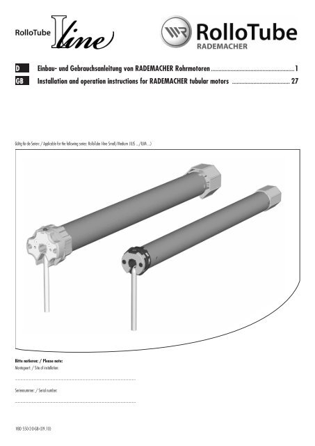
D Einbau- und Gebrauchsanleitung von RADEMACHER Rohrmotoren .......................................................1<br />
GB Installation and operation instructions for RADEMACHER tubular motors ...................................... 27<br />
Gültig für die Serien: / Applicable for the following series: <strong>RolloTube</strong> I-<strong>line</strong> Small/Medium (<strong>ILIS</strong> .../<strong>ILIM</strong> ...)<br />
Bitte notieren: / Please note:<br />
Montageort: / Site of installation:<br />
.................................................................................................................................<br />
Seriennummer: / Serial number:<br />
.................................................................................................................................<br />
VBD 550-2-D-GB-(09.10)
2<br />
i<br />
i<br />
i<br />
Sehr geehrte Kunden...<br />
...mit dem Kauf dieses Rohrmotors haben Sie sich für ein Qualitätsprodukt aus dem<br />
Hause RADEMACHER entschieden. Wir danken Ihnen für Ihr Vertrauen.<br />
Die RADEMACHER Rohrmotoren sind unter Aspekten des größten Komforts<br />
entstanden. Mit einem kompromisslosen Qualitätsanspruch und nach langen<br />
Versuchsreihen sind wir stolz, Ihnen dieses innovative Produkt zu präsentieren.<br />
Dahinter stehen alle hochqualifizierten<br />
Mitarbeiterinnen und Mitarbeiter aus<br />
dem Hause RADEMACHER.<br />
Diese Anleitung...<br />
...beschreibt Ihnen die Montage, den elektrischen Anschluss und die Bedienung von<br />
RADEMACHER Rohrmotoren der Serien <strong>ILIS</strong> ... und <strong>ILIM</strong> ...<br />
Bitte lesen Sie diese Anleitung vollständig durch und beachten Sie alle Sicherheitshinweise,<br />
bevor Sie mit den Arbeiten beginnen.<br />
Bitte bewahren Sie diese Anleitung auf und übergeben Sie die Anleitung bei einem<br />
Besitzerwechsel auch dem Nachbesitzer.<br />
Bei Schäden, die durch Nichtbeachtung dieser Anleitung und der Sicherheitshinweise<br />
entstehen, erlischt die Garantie. Für Folgeschäden, die daraus resultieren, übernehmen<br />
wir keine Haftung.<br />
Zeichenerklärung<br />
Lebensgefahr durch Stromschlag<br />
Dieses Zeichen weist Sie auf Gefahren bei Arbeiten an elektrischen Anschlüssen, Bauteilen<br />
etc. hin. Es fordert Sicherheitsmaßnahmen zum Schutz von Gesundheit und Leben der<br />
betroffenen Person.<br />
Hier geht es um Ihre Sicherheit.<br />
Beachten und befolgen Sie bitte alle so gekennzeichneten Hinweise.<br />
STOP<br />
CE-Zeichen und Konformität<br />
Das vorliegende Produkt erfüllt die Anforderungen der geltenden europäischen<br />
und nationalen Richtlinien.<br />
Die Konformität wurde nachgewiesen. Die entsprechenden Erklärungen und Unterlagen<br />
sind beim Hersteller hinterlegt.<br />
So warnen wir vor Fehlverhalten, das zu Personen- oder Sachschäden<br />
führen kann.<br />
HINWEIS/WICHtIG/ACHtuNG<br />
Auf diese Weise machen wir Sie auf weitere für die einwandfreie Funktion wichtige<br />
Inhalte aufmerksam.<br />
D
1<br />
5<br />
6<br />
3<br />
i Abbildungen/Illustrations<br />
(1) (2) (3) (4) (5) (6) (7) (8) (9) (10) (11) (12) (13) (14)<br />
2 3<br />
= (D/2)<br />
(5)<br />
(8)<br />
(11) (12) (13) (14)<br />
(9)<br />
(1)<br />
(10)<br />
(2)<br />
(4)<br />
L<br />
B C<br />
A<br />
L = A - (B + C)<br />
(5)<br />
(5)<br />
4<br />
7<br />
(17)<br />
(2) (3)<br />
(5) (6)<br />
(10)<br />
(4)<br />
8<br />
(16)<br />
(18) (8) (7) (19)<br />
(20)<br />
SW 40<br />
(20)<br />
(6)<br />
(5)<br />
D<br />
GB<br />
(15)
4<br />
Gesamtansicht (Abbildung )<br />
(1) Gegenlager<br />
(2) Kugellager<br />
(3) Achsstift der Walzenkapsel<br />
(4) Walzenkapsel<br />
(5) Wickelwelle<br />
(6) Befestigungsfeder<br />
(7) Rastbügel<br />
(8) Mitnehmer<br />
(9) Rohrmotor<br />
(10) Adapter<br />
(11) Setztaste<br />
(12) Antriebskopf<br />
(13) Antriebslager<br />
(14) Halteklammer<br />
(15) Motorkabel<br />
(16) Steuerung (z.B. Troll Comfort)<br />
(17) Rollladenpanzer<br />
(18) Limitring<br />
(19) Abtriebsadapter<br />
(20) Einhängeklammerm<br />
Bitte beachten:<br />
Kundenspezifischer Lieferumfang<br />
Vergleichen Sie nach dem Auspacken:<br />
◆ den Packungsinhalt mit den Angaben zum Lieferumfang auf der Verpackung.<br />
◆ den Motortyp mit den entsprechenden Angaben auf dem Typenschild.<br />
D
i<br />
Inhalt<br />
Einleitung / Zeichenerklärung ............................................................................2<br />
Gesamtansicht/Abbildungen ..............................................................................3<br />
Allgemeine Sicherheitshinweise ........................................................................6<br />
Richtige Verwendung /Einsatzbedingungen .........................................................6<br />
Falsche Verwendung ........................................................................................6<br />
Funktionsbeschreibung .....................................................................................7<br />
Funktion der Blockiererkennung .........................................................................7<br />
Funktion der Hinderniserkennung .......................................................................7<br />
Funktion des Behanglängenausgleichs.................................................................7<br />
Wichtige Montagehinweise ................................................................................8<br />
Einbau des Rohrmotors .....................................................................................8<br />
Montieren der Lager .........................................................................................8<br />
Länge der Wickelwelle ermitteln.........................................................................8<br />
Montage/Demontage des Adapters ....................................................................9<br />
Montage des Mitnehmers mit Freilauf .................................................................9<br />
Montage des Mitnehmers ohne Freilauf ...............................................................9<br />
Demontage des Mitnehmers ..............................................................................9<br />
Rohrmotor in die Wickelwelle schieben..............................................................10<br />
Vorbereitungen bei Verwendung von Präzisionsrohren ..........................................10<br />
Einstecken der Walzenkapsel ...........................................................................11<br />
Einbau des Motors in die Lager ........................................................................12<br />
Montage des Rollladenpanzers .........................................................................12<br />
Montage der Rollladenstopper oder einer Endschiene ...........................................12<br />
Sicherheitshinweise zum elektrischen Anschluss ..................................................13<br />
Das Motorkabel .............................................................................................13<br />
Elektrischer Anschluss des Rohrmotors /<br />
Steuerung eines Antriebs von einer Stelle mit 1poligem Schalter/Taster .................14<br />
Parallelschaltung von mehreren Motoren ...........................................................14<br />
Anschluss eines externen Tasters<br />
zur nachträglichen Einstellung der Endpunkte mit der Setzleitung .........................15<br />
Verwendung der Setzleitung zur manuellen Endpunkteinstellung ...........................15<br />
Anschluss eines Schnurschaltersetzgerätes .........................................................15<br />
Endpunkte einstellen ......................................................................................16<br />
Automatische Einstellung der Endpunkte ............................................................16<br />
Manuelle Einstellung der Endpunkte ..................................................................17<br />
Den oberen Endpunkt manuell setzen und den unteren automatisch einstellen ........17<br />
Den oberen Endpunkt automatisch einstellen und den unteren manuell setzen ........18<br />
Oberen und unteren Endpunkt manuell einstellen ................................................19<br />
Probelauf / Verändern der Endpunkte ...............................................................19<br />
Den Rohrmotor konfigurieren ...........................................................................20<br />
Die Werkseinstellungen bei der Inbetriebnahme laden .........................................20<br />
Das Reversieren nach der Hinderniserkennung ein-/ausschalten ............................21<br />
Den automatischen Behanglängenausgleich ein-/ausschalten .............................. 21<br />
Was tun, wenn ? ......................................................................................... 22<br />
Technische Daten ...........................................................................................24<br />
Parametrierung von KNX/EIB-Jalousie-Aktoren für RADEMACHER Rohrmotoren ........24<br />
Garantiebedingungen......................................................................................25<br />
D<br />
5
6<br />
i<br />
i<br />
Allgemeine Sicherheitshinweise<br />
Bei allen Arbeiten an elektrischen Anlagen besteht Lebensgefahr<br />
durch Stromschlag.<br />
◆ Der Netzanschluss des Rohrmotors und alle Arbeiten an elektrischen Anlagen<br />
dürfen nur durch eine zugelassene Elektrofachkraft nach den Anschlussplänen<br />
in dieser Anleitung erfolgen (s. Seite 13/14/15).<br />
◆ Führen Sie alle Montage- und Anschlussarbeiten im spannungslosen Zustand<br />
aus.<br />
Bei Nichtbeachtung besteht Lebensgefahr!<br />
Vorschriften bei Installation in Feuchträumen beachten.<br />
Beachten Sie besonders beim Einsatz in Feuchträumen die DIN VDE 0100, Teil 701<br />
und 702. Diese Vorschriften enthalten zwingende Schutzmaßnahmen.<br />
Der Einsatz defekter Geräte kann zur Gefährdung von Personen und<br />
zu Sachschäden führen (Stromschlag, Kurzschluss).<br />
◆ Verwenden Sie niemals defekte oder beschädigte Geräte.<br />
◆ Prüfen Sie Antrieb und Netzkabel auf Unversehrtheit.<br />
◆ Wenden Sie sich bitte an unseren Kundendienst (s. Seite 26) falls Sie Schäden<br />
am Gerät feststellen.<br />
Nach der Norm DIN EN 13659 muss dafür Sorge getragen werden,<br />
dass die für die Behänge festgelegten Verschiebebedingungen nach<br />
EN 12045 eingehalten werden.<br />
In ausgerollter Stellung muss bei einer Kraft von 150 N in Aufwärtsrichtung an der Unterkante<br />
die Verschiebung mindestens 40 mm betragen.<br />
Dabei ist besonders darauf zu achten, dass die Ausfahrgeschwindigkeit des Behanges<br />
auf den letzten 0,4 m kleiner als 0,2 m/s sein muss.<br />
Richtige Verwendung / Einsatzbedingungen<br />
Verwenden Sie die Rohrmotoren nur zum Öffnen und Schließen von<br />
Rollläden und Markisen.<br />
WICHtIG<br />
◆ Das Motorkabel muss innenliegend im Leerrohr unter Beachtung der örtlichen<br />
Elektrovorschriften bis zur Abzweigdose verlegt werden.<br />
◆ Verwenden Sie nur Original-Bauteile und -Zubehör des Herstellers.<br />
Verwenden Sie nur Rohrmotoren die in Ihrer Leistung den örtlichen<br />
Anforderungen entsprechen. Falsch dimensionierte Rohrmotoren können<br />
Schäden verursachen:<br />
◆ Ein unterdimensionierter Rohrmotor kann durch Überlastung<br />
beschädigt werden.<br />
◆ Ein überdimensionierter Rohrmotor kann zum Beispiel bei der automatischen<br />
Endpunkteinstellung den Rollladen bzw. den Rollladenkasten<br />
beschädigen.<br />
Lassen Sie sich bei der Auswahl eines Rohrmotors von einem Fachhändler beraten<br />
und beachten Sie die entsprechenden Zugkraftangaben auf unserer Homepage:<br />
www.rademacher.de<br />
Falsche Verwendung<br />
Verwenden Sie den Rohrmotor nie...<br />
...in Anlagen mit erhöhten sicherheitstechnischen Anforderungen od. erhöhter Unfallgefahr.<br />
Dies bedarf zusätzlicher Sicherheitseinrichtungen. Beachten Sie die jeweiligen gesetzlichen<br />
Regelungen zum Errichten solcher Anlagen.<br />
Bei unsachgemäßem Gebrauch besteht erhöhte Verletzungsgefahr.<br />
◆ Unterweisen Sie alle Personen im sicheren Gebrauch des Rohrmotors.<br />
◆ Verbieten Sie Kindern mit ortsfesten Steuerungen zu spielen.<br />
◆ Verhindern Sie, dass Personen mit eingeschränkten Fähigkeiten sowie Kinder mit<br />
ortsfesten Steuerungen oder mit der Fernsteuerung spielen.<br />
Bei Rollläden:<br />
◆ Beobachten Sie den sich bewegenden Rollladen und halten Sie Personen fern, bis die<br />
Bewegung beendet ist.<br />
◆ Führen Sie alle Reinigungsarbeiten am Rollladen im spannungslosen Zustand aus.<br />
Bei Markisenanlagen, die außerhalb der Sichtweite betrieben werden<br />
können:<br />
◆ Die Markise nicht betreiben, wenn Arbeiten in der Nähe ausgeführt werden<br />
(z. B. Fenster putzen).<br />
Bei automatisch betriebenen Markisen:<br />
◆ Die Markise vom Versorgungsnetz trennen, wenn Arbeiten in der Nähe durchgeführt<br />
werden.<br />
Regelmäßige Wartung von Markisen erhöht die Betriebssicherheit.<br />
◆ Kontrollieren Sie die Markise regelmäßig auf mangelhafte Balance oder beschädigte<br />
Leitungen und Federn.<br />
◆ Lassen Sie beschädigte Markisen von einem Fachbetrieb instand setzen.<br />
Einsatzbedingungen<br />
◆ Für den elektrischen Anschluss muss am Einbauort ständig ein 230 V /50 Hz<br />
Stromanschluss mit bauseitiger Freischaltvorrichtung (Sicherung) vorhanden<br />
sein.<br />
D
i<br />
i<br />
i<br />
i<br />
Funktionsbeschreibung<br />
Die RADEMACHER Rohrmotoren <strong>RolloTube</strong> I-<strong>line</strong> (<strong>ILIS</strong>.../<strong>ILIM</strong>...) dienen zum Öffnen und<br />
Schließen von Rollläden und Markisen.<br />
Die <strong>RolloTube</strong> I-<strong>line</strong> Rohrmotoren sind mit dem neuen Safe-Drive-Verfahren zur Positionserfassung,<br />
Drehmomentüberwachung und Hinderniserkennung ausgestattet. Die kompakte<br />
Bauweise und eine vollautomatische Endpunkteinstellung des Antriebs sorgen für eine<br />
einfache, komfortable Montage.<br />
Im täglichen Betrieb überzeugt der <strong>RolloTube</strong> I-<strong>line</strong> durch den automatischen Behanglängenausgleich,<br />
die Blockier- und Hinderniserkennung (mit Reversierung) für höchste Sicherheit<br />
und einen behangschonenden Lauf.<br />
Funktion der Blockiererkennung<br />
Der Rohrmotor stoppt und fährt automatisch kurz in die Gegenrichtung<br />
(reversiert), wenn der Rollladen im Hochlauf durch ein Hindernis<br />
(z. B. durch einen vereisten Rollladen blockiert wird).<br />
HINWEIS<br />
Vereisten Rollladen nicht bewegen und die Störung bzw. das Hindernis beseitigen.<br />
Funktion der Hinderniserkennung<br />
Der Rohrmotor stoppt und fährt automatisch kurz in die Gegenrichtung<br />
(reversiert), wenn der Rollladen beim tieflauf auf ein Hindernis<br />
stößt.<br />
HINWEIS<br />
Bei Bedarf kann das Reversieren nach der Hinderniserkennung ein- oder<br />
ausgeschaltet werden, s. Seite 21.<br />
Funktion des Behanglängenausgleichs<br />
Nach jedem automatischen Erlernen des oberen Endpunktes ist der<br />
Behanglängenausgleich aktiv. Danach fährt der Rohrmotor nicht mehr<br />
voll gegen den oberen Endpunkt, um den Rollladen und die Endpunkte<br />
zu schonen.<br />
Durch z. B. festgefrorene Rollläden können sich die automatisch erlernten<br />
Endpunkte und Laufwege mit der Zeit wieder verstellen. Zum Ausgleich<br />
fährt der Rohrmotor in regelmäßigen Zeitabständen (der Zyklus wird ab<br />
Werk entsprechend eingestellt) einmal automatisch gegen den oberen<br />
und unteren Endpunkt.<br />
Funktionsübersicht:<br />
◆ Inbetriebnahme mit einem Fahrbefehl. Selbstlernender Motor mit vollautomatischer<br />
Endpunkteinstellung.<br />
◆ Safe-Drive-Verfahren zur exakten Positionserfassung, Drehmomentüberwachung und<br />
Hinderniserkennung.<br />
◆ Blockier- und Hinderniserkennung inklusive Reversierung.<br />
◆ Durch das neue rastende FlexiClick-Prinzip ist die Hinderniserkennung frei wählbar.<br />
◆ Wartungsfreie Endpunkte dank automatischem Behanglängenausgleich.<br />
◆ Einfacher und schneller Einbau durch die kurze Bauform.<br />
◆ Optional erhältlich: Universelles RT ConfigTool zur individuellen Anpassung der<br />
Motorparameter.<br />
Bedingungen für die korrekte Funktion der Hinderniserkennung:<br />
◆ Der Mitnehmer muss mit Freilauf montiert sein (s. Abb. 4.a; Seite 9).<br />
◆ Der Rollladen muss mit Befestigungsfedern oder mit starren Wellenverbindern an der<br />
Wickelwelle montiert sein.<br />
◆ Der Rollladen muss immer senkrecht in die Führungsschiene des Fensters einlaufen.<br />
HINWEIS<br />
◆ Der Behanglängenausgleich erfolgt automatisch während des normalen Betriebs,<br />
sodass Sie ihn in der Regel gar nicht wahrnehmen.<br />
◆ Wird der obere Endpunkt manuell eingestellt, ist der Behanglängenausgleich nicht<br />
aktiv.<br />
D<br />
7
8<br />
Wichtige Montagehinweise<br />
WICHtIG<br />
◆ Vergleichen Sie vor der Montage die Angaben zur Spannung/Frequenz auf dem<br />
Typenschild mit denen des örtlichen Netzes.<br />
◆ Vor dem Einbau des Rohrmotors alle nicht zum Betrieb benötigten Leitungen<br />
und Einrichtungen abbauen bzw. außer Betrieb setzen.<br />
◆ Bewegliche Teile von Antrieben, die unter einer Höhe von 2,5 m vom Boden<br />
betrieben werden, müssen geschützt werden.<br />
◆ Wird der Rohrmotor mit einem Schalter mit AUS-Voreinstellung gesteuert, ist<br />
dieser Schalter in Sichtweite des Rohrmotors von sich bewegenden Teilen entfernt<br />
in mindestens 1,5 m Höhe anzubringen.<br />
◆ Die Wickelwelle unbedingt waagerecht montieren!<br />
Bei schiefer Aufwicklung des Rollladens können Schäden am Motor oder am<br />
Rollladen entstehen.<br />
◆ Der Deckel des Rollladenkastens muss leicht zugänglich und abnehmbar sein.<br />
◆ Demontieren Sie auf keinen Fall die Stopper der letzten Rollladenlamelle.<br />
Der Rollladen kann sonst eventuell bis in den Rollladenkasten durchrutschen und<br />
beschädigt werden.<br />
Einbau des Rohrmotors<br />
HINWEIS<br />
Die folgenden Einbauhinweise gelten für Standardeinbausituationen in Verbindung<br />
mit RADEMACHER-Rohrmotoren und -Zubehör.<br />
Der Antriebskopf (12) des Motors kann auf der rechten oder der linken Seite des<br />
Rollladenkastens eingebaut werden. In dieser Anleitung ist der Einbau für die rechte<br />
Seite dargestellt.<br />
Montieren der Lager (Abbildung )<br />
1. Bestimmen Sie zuerst die Position von Antriebs (13) - und Gegenlager<br />
(1) im Rollladenkasten.<br />
Wickeln Sie den Rollladenpanzer vollständig auf die Wickelwelle und messen Sie den<br />
Durchmesser D. Siehe Abbildung zur Bestimmung der Position der Lagermitte<br />
zur Führungsschiene.<br />
WICHtIG<br />
Im eingebauten Zustand muss der aufgewickelte Rollladen senkrecht in die Führungsschiene<br />
des Fensters einlaufen.<br />
Länge der Wickelwelle ermitteln (Abbildung )<br />
B<br />
B = Gegenlager/Walzenkapsel<br />
C = Antriebslager/Motor<br />
C<br />
2.<br />
1.<br />
2.<br />
3.<br />
Bei automatisch betriebenen Markisen:<br />
◆ Bei Markisen ist der Mindestabstand von 0,4 m zu den Teilen in der Umgebung<br />
bei voll ausgerollter Markise zu beachten.<br />
◆ Bei Einsatz in Markisenanlagen darf der unterste Punkt der Markise 1,8 m<br />
nicht unterschreiten.<br />
Notwendige Mindestbreite des Rollladenkastens:<br />
Rohrmotortyp: <strong>ILIS</strong> ... <strong>ILIM</strong> ...<br />
Mindestbreite ca.: 56 cm 67 cm<br />
Befestigen Sie die Lager je nach Lagertyp und bauseitigen Gegebenheiten.<br />
Montieren Sie das Antriebslager (13) so, dass die Setztaste (11) später gut zugänglich<br />
ist und das Motorkabel ohne Knick verlegt werden kann.<br />
Achten Sie auf den waagerechten Einbau der Lager. Ein schief aufgewickelter<br />
Rollladen kann den Antrieb blockieren und zerstören.<br />
Messen Sie den Wandabstand von Antriebs (13) - und Gegenlager (1)<br />
wie dargestellt.<br />
Messen Sie den Rollladenkasten aus und ermitteln Sie die nötige<br />
Wellenlänge (L).<br />
Länge der Wickelwelle: L = A - (B + C)<br />
Die Wickelwelle (5) auf das nötige Maß kürzen.<br />
Sägen Sie die Welle mit einer Eisensäge rechtwinklig auf Maß. Entgraten Sie die Welle<br />
innen und außen mit einer Feile.<br />
D
4.a (19)<br />
4.b<br />
4.c<br />
Montage/Demontage des Adapters (Abbildung )<br />
1. Montage des Adapters (10)<br />
Schieben Sie den Adapter (10) über den Limitring (18) am Antriebskopf<br />
bis er einrastet. Achten Sie dabei auf die richtige Lage der Nut im<br />
Adapter (10).<br />
Montage des Mitnehmers mit Freilauf (Abbildung ) *<br />
* = Auslieferungszustand<br />
(7)<br />
(8)<br />
(8)<br />
(8)<br />
(7)<br />
Montage des Mitnehmers ohne Freilauf (Abbildung )<br />
(19)<br />
Demontage des Mitnehmers (Abbildung )<br />
(19)<br />
2. Demontage des Adapters (10)<br />
Drücken Sie beide Haltefedern am Limitring (18) nach unten und<br />
ziehen Sie den Adapter (10) vom Limitring (18) ab.<br />
1.<br />
1.<br />
WICHtIG<br />
Soll der Rohrmotor mit der automatischen Endpunkteinstellung und mit<br />
der Hinderniserkennung arbeiten, müssen Sie den Mitnehmer (8) mit<br />
ausreichendem Freilauf montieren.<br />
Schieben Sie den Mitnehmer (8) so auf den Abtriebsadapter (19), dass<br />
er ausreichend Freilauf hat und hinter dem Rastbügel (7) einrastet.<br />
Bei ausreichendem Freilauf lässt sich der Mitnehmer (8) leicht hin- und<br />
herdrehen.<br />
1. Schieben Sie den Mitnehmer (8) so auf den Abtriebsadapter (19), dass<br />
er keinen Freilauf hat und hinter dem Rastbügel (7) einrastet.<br />
HINWEIS<br />
◆ Wird der Mitnehmer (8) ohne Freilauf montiert, arbeitet der Rohrmotor<br />
ohne Hinderniserkennung und ohne automatische Endpunkterkennung.<br />
◆ Das Montieren des Mitnehmers (8) ohne Freilauf kann notwendig sein,<br />
um bei Rollläden mit sehr geringem Eigengewicht oder bei schlecht<br />
fallenden Rollläden ein vorzeitiges Abschalten zu vermeiden.<br />
Drücken Sie die Seitenteile des Rastbügels (7) zusammen und ziehen<br />
die den Mitnehmer (8) vom Abtriebsadapter (19) ab.<br />
D<br />
9
1.<br />
10<br />
STOP<br />
5.a<br />
5.b<br />
5.c<br />
Rohrmotor in die Wickelwelle schieben (Abbildung )<br />
1<br />
1<br />
Schlagen Sie nie den Motor (9) mit<br />
Gewalt in die Wickelwelle (5) ein.<br />
Das führt zu seiner Zerstörung.<br />
Schieben Sie zuerst den Mitnehmer (8) in die Wickelwelle (5).<br />
WICHtIG<br />
Bei Wickelwellen mit innenliegender Falz muss der Motor (9) ausreichend Freiraum haben.<br />
<br />
<br />
2. Drücken Sie danach die Wickelwelle (5) vollständig auf den Adapter (10).<br />
WICHtIG<br />
Achten Sie darauf, dass der Adapter (10) während der Montage nicht vom Limitring<br />
(18) am Antriebskopf (12) abrutscht. Es kommt sonst zu Fehlfunktionen, s. Seite 22.<br />
Vorbereitungen bei Verwendung von Präzisionsrohren (Abbildungen - )<br />
WICHtIG<br />
◆ Bitte verwenden Sie ausschließlich Präzisionsrohre aus Aluminium.<br />
◆ Bei Verwendung von Achtkant-Stahlwellen entfallen die folgenden Schritte.<br />
ALuMINIuM<br />
Rollotube I-<strong>line</strong> Small (<strong>ILIS</strong>...)<br />
Rollotube I-<strong>line</strong> Medium (<strong>ILIM</strong>...)<br />
1. Messen Sie den Abstand zwischen Adapter (10) und dem hinteren<br />
Drittel des Mitnehmers (8) und zeichnen Sie diesen Abstand auf das<br />
Präzisionsrohr.<br />
2. Sägen Sie am Ende des Präzisionsrohrs eine Nut 1 aus, damit der Nocken<br />
des Adapters (10) ganz in das Rohr geschoben werden kann.<br />
HINWEIS<br />
◆ Zwischen der Nut 1 und dem Nocken darf kein Spiel vorhanden sein.<br />
◆ Die Abmessungen für die Nut 1 sind vom jeweiligen Rohrmotortyp abhängig,<br />
s. Abbildungen.<br />
D
5.d<br />
5.e<br />
5.f<br />
Vorbereitungen bei Verwendung von Präzisionsrohren (Abbildungen - )<br />
STOP<br />
Einstecken der Walzenkapsel (Abbildung )<br />
1. Schieben Sie die Walzenkapsel (4) in die Wickelwelle (5) und<br />
stecken Sie anschließend das Kugellager (2) auf den Achsstift (3).<br />
3. Den Rohrmotor in das Präzisionsrohr schieben.<br />
4.<br />
5.<br />
Markieren Sie vier Befestigungslöcher und bohren Sie diese anschließend<br />
durch das Präzisionsrohr in den Mitnehmer (8).<br />
ACHtuNG<br />
◆ Bohren Sie nie tiefer als 10 mm in den Mitnehmer (8).<br />
◆ Nie im Bereich des Antriebs bohren. Das führt zu seiner Zerstörung.<br />
Das Präzisionsrohr am Mitnehmer (8) festschrauben oder vernieten.<br />
Verwenden Sie vier selbstschneidende Blechschrauben oder vier Blindnieten.<br />
D<br />
11
1.<br />
12<br />
STOP<br />
9<br />
Einbau des Motors in die Lager (Abbildung )<br />
Antriebslager (als Clicklager)/(13)<br />
Drücken Sie den Antriebskopf (12) leicht in das Antriebslager (13),<br />
bis er eingerastet ist.<br />
HINWEIS<br />
Die Setztaste (11) muss gut zugänglich sein.<br />
Die Rohrmotoren können in 4 Stellungen in das Clicklager (13) eingebaut werden.<br />
Durch Spreizen der Halteklammer (14) können Sie die Motoren jederzeit wieder aus<br />
dem Clicklager (13) lösen.<br />
Antriebslager (alle anderen Lagervarianten)<br />
Hängen Sie den Antriebskopf (12) in das jeweilige Antriebslager und sichern Sie ihn<br />
entsprechend, z.B. mit einem Splint.<br />
Montage des Rollladenpanzers (Abbildung /)<br />
Montieren Sie den Rollladenpanzer (17) mit Befestigungsfedern (6) (Zubehör) an<br />
der Wickelwelle (5).<br />
Nie im Bereich des Antriebs bohren<br />
oder schrauben um den Rollladen zu<br />
befestigen.<br />
WICHtIG<br />
◆ Bei einem Betrieb ohne Stopper kann der Rollladen in den Rollladenkasten<br />
fahren und dort beschädigt werden.<br />
Der Rollladen muss immer über Stopper oder über eine Endschiene verfügen.<br />
(21)<br />
2.<br />
3.<br />
1.<br />
2.<br />
2.a<br />
Gegenlager (1)<br />
Stecken Sie das andere Ende der Wickelwelle (5) mit dem Kugellager<br />
(2) in das Gegenlager (1).<br />
Falls Sie ein anderes Antriebslager als das RADEMACHER-Clicklager<br />
verwenden, müssen Sie jetzt ggf. den Antrieb mit einem zweiten<br />
Splint sichern.<br />
Korrigieren Sie leichte Maßungenauigkeiten durch Einschieben oder<br />
Herausziehen der Walzenkapsel (4).<br />
WICHtIG<br />
◆ Sichern Sie die Walzenkapsel (4) zum Schluss mit einer Schraube.<br />
◆ Die Walzenkapsel (4) muss mindestens mit 2/3 ihrer Länge in der<br />
Wickelwelle (5) stecken.<br />
Schieben Sie die Befestigungsfedern (6) auf die oberste Lamelle des<br />
Rollladenpanzers (17).<br />
Setzen Sie alle 40 cm eine Befestigungsfeder (6) in die rechteckigen<br />
Löcher der Wickelwelle (5).<br />
Verwenden Sie bei Wickelwellen SW 40 (mit Außenfalz) Einhängeklammern<br />
(20) zur Montage der Befestigungsfedern (6); siehe Abbildung .<br />
Montage der Rollladenstopper oder einer Endschiene (Abbildung 9)<br />
Die Abbildung zeigt einen Rollladen mit außenliegenden Stoppern (21), die an den<br />
Schienen installiert werden.<br />
WICHtIG<br />
◆ Bei der automatischen Einstellung der Endanschläge ohne Stopper (21),<br />
oder beim Betrieb ohne Stopper (21) kann der Rollladen in den Rollladenkasten<br />
fahren und dort beschädigt werden.<br />
Der Rollladen (17) muss über Stopper (21) oder über eine Endschiene verfügen.<br />
Montieren Sie daher noch vor der Inbetriebnahme das entsprechende Bauteil<br />
(s. Beispiel in Abbildung 9).<br />
D
Sicherheitshinweise zum Elektrischen Anschluss<br />
Bei allen Arbeiten an elektrischen Anlagen besteht Lebensgefahr<br />
durch Stromschlag.<br />
◆ Der Netzanschluss des Rohrmotors und alle Arbeiten an elektrischen Anlagen<br />
dürfen nur durch eine zugelassene Elektrofachkraft nach den Anschlussplänen<br />
in dieser Anleitung erfolgen.<br />
◆ Trennen Sie die Zuleitung allpolig vom Netz und sichern Sie sie gegen unbeabsichtigtes<br />
Einschalten.<br />
◆ Prüfen Sie die Anlage auf Spannungsfreiheit.<br />
◆ Führen Sie alle Montage- und Anschlussarbeiten nur im spannungslosen<br />
Zustand aus.<br />
Kurzschlussgefahr durch beschädigte Kabel.<br />
◆ Verlegen Sie alle Kabel im Rollladenkasten so, dass diese nicht durch bewegliche<br />
Teile beschädigt werden können.<br />
◆ Die Netzanschlussleitung dieses Antriebs darf nur durch den gleichen Leitungstyp<br />
angeschlossen werden. Wenden Sie sich ggf. an den Kundendienst.<br />
10<br />
Das Motorkabel (Abbildung j)<br />
(11)<br />
(15)<br />
L1<br />
L1<br />
N<br />
PE<br />
Bei festinstallierten Geräten...<br />
...muss gemäß DIN VDE 0700 installationsseitig eine Trennvorrichtung für jede Phase<br />
vorhanden sein. Als Trennvorrichtung gelten Schalter mit einer Kontaktöffnungsweite von<br />
min. 3 mm (z. B. LS-Schalter, Sicherungen od. FI-Schalter).<br />
Kurzschlussgefahr durch Wasser bei falscher Kabelführung.<br />
Verlegen Sie das Motorkabel (15) nie direkt senkrecht nach oben, sonst kann evtl.<br />
Wasser über das Kabel in den Motor laufen und diesen zerstören. Verlegen Sie das Kabel<br />
in einer Schlaufe. Die Schlaufe bewirkt, dass am Kabel ablaufendes Wasser am tiefsten<br />
Punkt der Schlaufe gesammelt wird und dort abtropft.<br />
STOP<br />
1. Führen Sie das Motorkabel (15) nach dem Einhängen des Motors in<br />
die dafür vorgesehene Abzweig- oder Schalterdose.<br />
Farbskala der Motorleitung (15)<br />
= Setzleitung (weiß)<br />
L1 = (schwarz) *<br />
L1 = (braun) *<br />
N = Neutralleiter (blau)<br />
PE = Erdung (grün/gelb)<br />
(11) = Setztaste am Rohrmotor<br />
* HINWEIS Die tatsächliche Laufrichtung des Rohrmotors und des Behangs hängen<br />
von der Einbaurichtung und von der Verdrahtung des Rohrmotors ab.<br />
D<br />
13
14<br />
Elektrischer Anschluss des Rohrmotors (Abbildung k)<br />
11 (a)<br />
12<br />
Steuerung eines Antriebs von einer Stelle mit 1poligem Schalter / taster<br />
(b)<br />
(c)<br />
(b)<br />
(c)<br />
(d)<br />
(h) (i)<br />
(e) (f) (g)<br />
(j)<br />
Legende<br />
(a) = Setztaste (11)<br />
(b) = Steuergerät (z. B. 1poliger Schalter/ Taster)<br />
(c) = Netz 230V/50Hz<br />
(d) = Schalterdose<br />
Anschlussbelegung<br />
(e) = PE grün/gelb<br />
(f) = N blau<br />
(g) = L1 schwarz<br />
(h) = (▲) schwarz<br />
(i) = (▼) braun<br />
(j) = weiß (Setzleitung)<br />
Parallelschaltung von mehreren Motoren (Abbildung l)<br />
Legende<br />
(a) = Abzweigdose<br />
(b) = Steuergerät z. B. 1poliger Schalter/ Taster<br />
(c) = Netz 230V/50Hz<br />
WICHtIG<br />
◆ Die Setzleitung (j) muss nach Einstellung der Endpunkte am Neutralleiter (f) angeschlossen<br />
werden.<br />
Installationsbeispiel Die Parallelschaltung mehrerer RADEMACHER Rohrmotoren ist möglich. Die Anzahl der parallel zu<br />
schaltenden Motoren ist von der Belastbarkeit der Schaltstelle und der Sicherung abhängig.<br />
HINWEIS<br />
Im Falle der Parallelschaltung ist jedoch keine individuelle Steuerung des einzelnen Motors mehr möglich.<br />
Endpunkte einstellen<br />
Bei der Parallelschaltung mehrerer Rohrmotoren müssen Sie für jeden einzelnen Rohrmotor ebenfalls<br />
beide Endpunkte automatisch oder manuell einstellen, s. Seite 16. Dazu muss die Setzleitung jedes<br />
Rohrmotors zugänglich sein.<br />
WICHtIG<br />
(a)<br />
Verlegen Sie deshalb die Setzleitung (j) jedes einzelnen Rohrmotors bis in die jeweilige Abzweigdose,<br />
dadurch ist auch eine nachträgliche manuelle Einstellung der Endpunkte jederzeit möglich.<br />
Parallelschaltung mit Jalousieschaltern oder Jalousietastern<br />
Mit Jalousieschaltern oder Jalousietastern von RADEMACHER (Art.-Nr.: 2780 - 2787) lassen sich bis<br />
zu 5 Motoren parallel schalten.<br />
Parallelschaltung mit RADEMACHER Steuerungen (z. B. troll Comfort)<br />
Anzahl der jeweils parallel schaltbaren Rohrmotoren, s. Technische Daten.<br />
D
13<br />
Anschluss eines externen tasters (230V/50Hz) (Abbildung m) ...<br />
...zur nachträglichen Einstellung der Endpunkte mit der Setzleitung<br />
(22)<br />
(a)<br />
(b)<br />
(c)<br />
(d)<br />
(h) (i)<br />
(e) (f) (g)<br />
(j)<br />
(k)<br />
WICHtIG<br />
Nach Einstellung der Endpunkte den externen Taster wieder abklemmen und die Setzleitung (j) am Neutralleiter<br />
(f) anschließen, siehe Abbildung k.<br />
Verwendung der Setzleitung zur manuellen Endpunkteinstellung<br />
Über die Setzleitung (j) wird die Funktion der Motorsetztaste (11) nach außen<br />
geführt. Wenn Sie die Setzleitung (j) an einen externen Taster anschließen (s. oben),<br />
können Sie diesen externen Taster als Setztaste zur Einstellung der Endpunkte nutzen.<br />
Führen Sie die Setzleitung (j) des Motorkabels (15) bis zur jeweiligen Schaltstelle<br />
(z. B. bis in die Schalterdose).<br />
Anschluss eines Schnurschaltersetzgerätes<br />
Lebensgefahr durch Abreißen des Motorkabels (15).<br />
Achten Sie darauf, dass das Motorkabel (15) während der Einstellungen nicht durch<br />
die Wickelwelle (5) erfasst bzw. abgerissen wird.<br />
Legende<br />
(a) = Setztaste (11)<br />
(b) = Steuergerät (z. B. 1poliger Schalter/ Taster)<br />
(c) = Netz 230V/50Hz<br />
(d) = Schalterdose<br />
Anschlussbelegung<br />
(e) = PE grün/gelb<br />
(f) = N blau<br />
(g) = L1 schwarz<br />
(h) = (▲) schwarz<br />
(i) = (▼) braun<br />
(j) = weiß (Setzleitung)<br />
(k) = externer Taster<br />
Verwendung der Setzleitung (j) bei Erstinstallation<br />
Bei einer Erstinstallation kann der Rollladenmonteur das Motorkabel (15) vollständig<br />
an ein im Fachhandel erhältliches Schnurschaltersetzgerät (22) (Art. Nr. 4090)<br />
anschließen, um damit die Endpunkte Ihres Rohrmotors einzustellen.<br />
HINWEIS<br />
Beachten Sie die verschiedenen Einstellmöglichkeiten für die Endpunkte auf Seite 16.<br />
Verwendung der Setzleitung (j) zum nachträglichen Verändern der<br />
Endpunkte:<br />
Wollen Sie nachträglich die Endpunkte einer bestehenden Rollladeninstallation ändern,<br />
müssen Sie einen Elektriker beauftragen, die Setzleitung (j) gemäß dem Anschlussplan<br />
m an einen handelsüblichen, externen Taster (230 V/50 Hz) anzuschließen. Sie können<br />
dann mit diesem Taster und Ihrer Rollladensteuerung die Endpunkte verändern.<br />
Verwendung der Setzleitung (j) nach Einstellung der Endpunkte:<br />
Nach Einstellung der Endpunkte müssen Sie das jeweilige externe Schaltgerät wieder<br />
abklemmen und den Motoranschluss gemäß dem Anschlussplan k vornehmen.<br />
WICHtIG<br />
Die Setzleitung (j) muss nach Einstellung der Endpunkte am Neutralleiter<br />
(f) angeschlossen werden.<br />
1. Öffnen Sie die Klemmkontakte durch Drücken der Stößel und klemmen<br />
Sie alle Adern des Motorkabels (15) entsprechend Ihren Funktionen an,<br />
s. Abbildung j.<br />
D<br />
15
1.<br />
2.<br />
3.<br />
4.<br />
5.<br />
16<br />
Endpunkte einstellen<br />
Sie haben verschiedene Möglichkeiten zur Einstellung der Endpunkte,<br />
die wir Ihnen im Folgenden beschreiben:<br />
◆ Automatische Einstellung der Endpunkte.<br />
◆ Manuelle Einstellung der Endpunkte:<br />
- Den oberen Endpunkt manuell setzen und den unteren Endpunkt<br />
per Hindernisserkennung einstellen.<br />
- Den oberen Endpunkt mit Hilfe der Blockiererkennung einstellen und den<br />
unteren Endpunkt manuell setzen.<br />
- Den oberen/unteren Endpunkt manuell einstellen.<br />
Wichtiger Zusammenhang zwischen der Einstellung des unteren<br />
Endpunktes und der Montage des Mitnehmers.<br />
◆ Wird der Mitnehmer ohne Freilauf montiert, schaltet der Rohrmotor nicht automatisch<br />
ab, da er kein Hindernis bzw. den unteren Endpunkt nicht erkennt.<br />
◆ Wird der Mitnehmer mit Freilauf montiert, schaltet der Rohrmotor erst dann automatisch<br />
ab, sobald der Mitnehmer den Freilauf überwunden hat und die Rollladenlamellen<br />
geschlossen sind.<br />
Automatische Einstellung der Endpunkte<br />
Mit Hilfe dieser Werkseinstellung kann der Rohrmotor die Endpunkte automatisch suchen<br />
und einstellen.<br />
HINWEIS<br />
Falls die automatische Einstellung der Endpunkte fehlschlägt, müssen Sie den Rohrmotor<br />
auf die Werkseinstellungen zurücksetzen (s. Seite 20), um den Vorgang zu wiederholen.<br />
▲ ▼<br />
WICHtIG<br />
◆ Bei einem Betrieb ohne Stopper (21) kann der Rollladen in den Rollladenkasten<br />
fahren und dort beschädigt werden.<br />
Der Rollladen muss über Stopper (21) oder über eine Endschiene verfügen.<br />
◆ Für beide Laufrichtungen, Auf (▲)/Ab (▼), müssen Endpunkte gesetzt werden,<br />
bei deren Erreichen der Motor abschaltet.<br />
◆ Der Rohrmotor muss vollständig eingebaut sein.<br />
◆ Im Bereich des unteren Endpunktes muss eine ausreichend feste Begrenzung (z. B.<br />
eine Fensterbank) montiert sein, falls die Einstellung des Endpunktes automatisch<br />
erfolgen soll.<br />
Bedingungen für die automatische Einstellung der Endpunkte:<br />
◆ Der Mitnehmer (8) muss mit Freilauf montiert sein (s. Abb. 4.a; Seite 9).<br />
WICHtIG<br />
◆ Während der automatischen Endpunkteinstellung darf der Rohrmotor nie ohne<br />
Netzspannung sein. Der Netzanschluss muss durchgängig gewährleistet sein.<br />
Den Rollladen zuerst aufwärts fahren.<br />
Drücken Sie dazu je nach Einbausituation des Rohrmotors die Auf-(▲)-Taste oder die Ab-(▼)-Taste.<br />
Der Rollladen fährt gegen den oberen Anschlag und schaltet kurz ab.<br />
Anschließend kehrt der Rohrmotor die Drehrichtung um und fährt den Rollladen nach unten.<br />
Sobald der Rollladen vollständig geschlossen ist, schaltet der Rohrmotor automatisch ab. Die Position des Rollladens<br />
wird als unterer Endpunkt gespeichert.<br />
Im Anschluss fährt der Rollladen erneut nach oben und schaltet ab. Er speichert diese Position als oberen Endpunkt.<br />
HINWEIS<br />
Im laufenden Betrieb wird der Rollladen entlastet, indem er nicht ständig durch das Anschlagen der Stopper unter Zugspannung steht.<br />
6. Schalten Sie zum Schluss den Rohrmotor für einige Sekunden stromlos. Danach ist der Rohrmotor betriebsbereit.<br />
D
1.<br />
2.<br />
SEt<br />
oder<br />
3.<br />
SEt oder<br />
4.<br />
Manuelle Einstellung der Endpunkte<br />
Erstinstallation<br />
Bei einer Erstinstallation kann der Rollladenmonteur die Einstellung der Endpunkte<br />
mit Hilfe der Setztaste (11) am Motor oder mit einem im Fachhandel erhältlichen<br />
Schnurschaltersetzgerät (22) vornehmen.<br />
Nähere Angaben finden Sie in der <strong>Bedienungsanleitung</strong> zum Schnurschaltersetzgerät.<br />
Nachträgliche Änderung der Endpunkte mit externen Steuerungen<br />
Wollen Sie nachträglich die Endpunkte Ihres Rohrmotors verändern, können Sie, wie<br />
zuvor gezeigt, mit einem externen taster als Setztaste oder Ihrer Rollladensteuerung<br />
(z.B. Troll Comfort) die Endpunkte neu einstellen.<br />
tastenbelegung am Schnurschaltersetzgerät (22)<br />
SEt<br />
Den oberen Endpunkt manuell setzen und den unteren automatisch einstellen<br />
SEt<br />
Setztaste<br />
Laufrichtung (▲/▼)<br />
umschalten<br />
oder<br />
STOP<br />
Den Rollladen zuerst aufwärts fahren.<br />
WICHtIG<br />
◆ Bei einem Betrieb ohne Stopper (21) kann der Rollladen in den Rollladenkasten<br />
fahren und dort beschädigt werden.<br />
Der Rollladen muss über Stopper (21) oder über eine Endschiene verfügen.<br />
◆ Sie müssen für beide Laufrichtungen, Auf (▲)/Ab (▼), Endpunkte setzen, bei<br />
deren Erreichen der Motor abschaltet.<br />
◆ Dazu muss der Rohrmotor vollständig eingebaut sein.<br />
◆ Demontieren Sie auf keinen Fall die mechanischen Stopper der letzten<br />
Rollladenlamelle.<br />
◆ Der Rollladenkasten muss geöffnet sein und die Setztaste (11) am Rohrmotor<br />
muss frei zugänglich sein.<br />
◆ Fahren Sie nicht gegen die mechanischen Anschläge und halten Sie einen<br />
Sicherheitsabstand von 2-3 cm ein.<br />
Bei geöffnetem Rollladenkasten besteht Verletzungsgefahr durch<br />
Quetschen der Hand.<br />
Greifen Sie nie bei laufendem Motor in den Bereich der Wickelwelle.<br />
Die entsprechende Setztaste* drücken und festhalten, bis der obere Endpunkt erreicht ist.<br />
* am Motor, dem Schnurschaltersetzgerät (22) oder dem externen Taster.<br />
Die Setztaste sofort loslassen, wenn der Rollladen die gewünschte Position erreicht hat.<br />
Der Motor stoppt und der obere Endpunkt ist gespeichert.<br />
Durch kurzes tippen der Setztaste können Sie den Endpunkt in kleinen Schritten korrigieren.<br />
WICHtIG<br />
Kommt es während der Einstellungen zu einer Fehlfunktion, läuft z.B. der Rohrmotor nur eine Umdrehung lang auch beim Drücken der<br />
Setztaste, ist Ihr Rohrmotor wahrscheinlich nicht defekt, eventuell ist der Adapter (10) vom Motorkopf abgerutscht.<br />
Prüfen und korrigieren Sie ggf. den richtigen Sitz des Adapters (10), (s. Seite 22).<br />
5.<br />
▼<br />
Fahren Sie zum Schluss den Rollladen nach unten. Sobald der Rollladen vollständig geschlossen ist, schaltet der<br />
Rohrmotor automatisch ab. Die Position des Rollladens wird als unterer Endpunkt gespeichert.<br />
HINWEIS<br />
Falls diese Einstellung der Endpunkte fehlschlägt, müssen Sie den Rohrmotor auf die Werkseinstellungen zurücksetzen<br />
(s. Seite 20), um den Vorgang zu wiederholen.<br />
6.<br />
▲ ▼<br />
Schalten Sie zum Schluss den Rohrmotor für einige Sekunden stromlos. Danach ist der Rohrmotor betriebsbereit.<br />
D<br />
17
1.<br />
2.<br />
3.<br />
SEt<br />
oder<br />
4.<br />
SEt oder<br />
5.<br />
6.<br />
18<br />
Den oberen Endpunkt automatisch einstellen und den unteren manuell setzen<br />
▲ ▼<br />
SEt<br />
oder<br />
Den Rollladen aufwärts gegen den oberen Anschlag fahren, bis der Rohrmotor automatisch stoppt.<br />
WICHtIG<br />
Greifen Sie während der Fahrt nicht in den Ablauf ein. Der Rollladen muss ohne Unterbrechung nach oben fahren.<br />
Anschließend kehrt der Rohrmotor die Drehrichtung um und fährt den Rollladen nach unten.<br />
Die entsprechende Setztaste* drücken und festhalten, bis der untere Endpunkt erreicht ist.<br />
* am Motor, dem Schnurschaltersetzgerät (22) oder dem externen Taster.<br />
Die Setztaste sofort loslassen, wenn der Rollladen die gewünschte Position erreicht hat.<br />
Der Motor stoppt und beide Endpunkte sind gespeichert.<br />
HINWEIS<br />
Diese Methode bietet sich an, falls Sie Lüftungsschlitze zwischen den Rollladenlamellen geöffnet lassen wollen.<br />
Durch kurzes tippen der Setztaste können Sie den unteren Endpunkt in kleinen Schritten korrigieren.<br />
WICHtIG<br />
Kommt es während der Einstellungen zu einer Fehlfunktion, läuft z. B. der Rohrmotor nur eine Umdrehung lang, auch beim Drücken<br />
der Setztaste, ist Ihr Rohrmotor wahrscheinlich nicht defekt, eventuell ist der Adapter (10) vom Motorkopf abgerutscht.<br />
Prüfen und korrigieren Sie ggf. den richtigen Sitz des Adapters (10), (s. Seite 22).<br />
HINWEIS<br />
Falls diese Einstellung der Endpunkte fehlschlägt, müssen Sie den Rohrmotor auf die Werkseinstellungen zurücksetzen (s. Seite 20), um den<br />
Vorgang zu wiederholen.<br />
Schalten Sie zum Schluss den Rohrmotor für einige Sekunden stromlos. Danach ist der Rohrmotor betriebsbereit.<br />
D
1.<br />
2.<br />
SEt<br />
oder<br />
3. oder<br />
SEt<br />
4.<br />
Oberen / unteren Endpunkt manuell einstellen<br />
▲ ▼<br />
SEt<br />
oder<br />
Probelauf / Verändern der Endpunkte<br />
Kontrollieren Sie Ihre Einstellungen und lassen Sie den Rollladen in<br />
beide Richtungen laufen, bis die Endpunkte den Motor ausschalten.<br />
thermoschutz<br />
Die Rohrmotoren sind für den Kurzzeitbetrieb (ca. 4 Min.) ausgelegt.<br />
Das Überschreiten dieser Zeit oder häufiges Umschalten führen zur Erwärmung des<br />
Motors und zur Abschaltung durch den Thermoschutz.<br />
Lassen Sie den Motor in diesem Fall 20 Minuten abkühlen.<br />
Schalter/Steuerung zuerst in den Hochlauf (▲) / tieflauf (▼) schalten.<br />
HINWEIS<br />
Trennen Sie bei falscher Drehrichtung die Zuleitung vom Netz und vertauschen Sie die beiden Adern L1 und L1 .<br />
Die entsprechende Setztaste* drücken und festhalten, bis der gewün schte Endpunkt erreicht ist.<br />
Der Rollladen läuft hoch / runter<br />
* am Motor, dem Schnurschaltersetzgerät (22) oder dem externen Taster.<br />
Die Setztaste sofort loslassen, wenn der Rollladen die gewünschte Position erreicht hat.<br />
Der Motor stoppt und der obere/untere Endpunkt ist gespeichert.<br />
Durch kurzes tippen der Setztaste, können Sie den Endpunkt in kleinen Schritten korrigieren.<br />
WICHtIG<br />
Kommt es während der Einstellungen zu einer Fehlfunktion, läuft z.B. der Rohrmotor nur eine Umdrehung lang, auch beim Drücken der<br />
Setztaste, ist Ihr Rohrmotor wahrscheinlich nicht defekt, eventuell ist der Adapter (10) vom Motorkopf abgerutscht.<br />
Prüfen und korrigieren Sie ggf. den richtigen Sitz des Adapters (10), (s. Seite 22).<br />
HINWEIS<br />
Auch bei einem Stromausfall bleiben die Endpunkte dauerhaft erhalten.<br />
Verändern der Endpunkte<br />
Fahren Sie den Rollladen in die Mittelstellung zurück und beginnen Sie von vorn.<br />
D<br />
19
1.<br />
2.<br />
20<br />
Den Rohrmotor konfigurieren<br />
Mit Hilfe eines Schnurschaltersetzgerätes (22) können Sie bei der Erstinstallation den<br />
Rohrmotor individuell konfigurieren.<br />
Folgende Einstellungen sind möglich.<br />
◆ Die Werkseinstellungen laden.<br />
◆ Das Reversieren nach der Hinderniserkennung ein-/ausschalten.<br />
◆ Den Behanglängenausgleich ein-/ausschalten.<br />
Die Werkseinstellungen bei der Inbetriebnahme laden<br />
Nach dem Laden der Werkseinstellungen ist die automatische Endpunkteinstellung<br />
wieder möglich.<br />
HINWEIS<br />
Wir empfehlen diese Einstellung eventuell mit zwei Personen durchzuführen.<br />
WICHtIG<br />
Der Rohrmotor darf nicht in Betrieb sein.<br />
1. + 2.<br />
SEt<br />
30 s<br />
Den Rohrmotor einschalten (▲/▼).<br />
HINWEIS<br />
Weitere Einstellungen können Sie mit dem optional erhältlichen RT ConfigTool durchführen.<br />
Bitte beachten Sie dazu die Angaben auf unserer Internetseite (www.rademacher.de).<br />
Werkseinstellungen:<br />
Endpunkte: keine Endpunkte gespeichert<br />
Automatische Einstellung der Endpunkte: aktiviert<br />
Reversieren nach Hinderniserkennung: aktiviert<br />
Reversieren nach Blockiererkennung: aktiviert<br />
Behanglängeausgleich: aktiviert<br />
Zuerst die Setztaste (11) am Rohrmotor und anschließend die SEt-taste am Schnurschaltersetzgerät (22) (eventuell<br />
durch eine zweite Person) drücken. Beide tasten für ca. 30 Sekunden gedrückt halten.<br />
3. 30 s Nach ca. 30 Sekunden quittiert der Rohrmotor das Laden der Werkseinstellungen durch kurzes Auf- und Abfahren.<br />
D
1.<br />
1.<br />
Das Reversieren nach der Hinderniserkennung ein-/ausschalten<br />
1. 2.<br />
SEt +<br />
10 s<br />
Zuerst die SEt-taste am Schurschaltersetzgerät (22) drücken und gedrückt halten und anschließend die Auf- oder<br />
Ab-taste 10 Sekunden lang drücken und halten.<br />
Nach 10 Sekunden ist die Funktion Reversieren ein/bzw. ausgeschaltet.<br />
Werkseinstellung = Reversieren ist eingeschaltet<br />
2. Nach ca. 10 Sekunden quittiert der Rohrmotor das Ein- bzw. Ausschalten der Reversierung durch ein kurzes Anfahren.<br />
10 s<br />
Den automatischen Behanglängengausgleich ein-/ausschalten<br />
1. 2.<br />
SEt +<br />
20 s<br />
Zuerst die SEt-taste am Schnurschaltersetzgerät (22) drücken und gedrückt halten und anschließend die<br />
Auf (▲)- oder Ab (▼)-taste 20 Sekunden lang drücken und halten.<br />
◆ Nach 10 Sekunden ist die Funktion Reversieren ein- bzw. ausgeschaltet.<br />
◆ Nach 20 Sekunden ist die Funktion Behanglängenausgleich ein- bzw. ausgeschaltet.<br />
Werkseinstellung = Der Behanglängenausgleich ist eingeschaltet<br />
2. Beachten Sie die Reaktionen des Rohrmotors.<br />
10 s<br />
Nach ca. 10 Sekunden quittiert der Rohrmotor das Verstreichen der Reversiereinstellung.<br />
Halten Sie die tasten weiterhin gedrückt:<br />
20 s<br />
Nach ca. 20 Sekunden quittiert der Rohrmotor das Ein-/Ausschalten des Behanglängenausgleichs jeweils mit einem<br />
kurzen Anfahren.<br />
D<br />
21
22<br />
i<br />
Was tun, wenn... ?<br />
...der Motor nicht läuft?<br />
Mögliche ursache:<br />
◆ Die Netzspannung fehlt.<br />
Lösung:<br />
◆ Prüfen Sie mit einem Spannungsmessgerät, ob die Versorgungsspannung<br />
(230 V) anliegt und überprüfen Sie die Verdrahtung.<br />
◆ Beachten Sie besonders die Angaben zu den unzulässigen Anschlussarten.<br />
...die Drehrichtung falsch ist?<br />
Mögliche ursache:<br />
◆ Die Steuerleitungen sind vertauscht.<br />
Lösung:<br />
◆ Trennen Sie die Zuleitung vom Netz und vertauschen Sie die Adern für<br />
L1 und L1 .<br />
...der Rohrmotor bei Einstellarbeiten und Probelauf nach kurzem<br />
Lauf stehen bleibt?<br />
Mögliche ursache:<br />
◆ Der Adapter (10) ist möglicherweise vom Limitring (18) am Antriebskopf (12)<br />
abgerutscht.<br />
Lösung:<br />
◆ Prüfen Sie, ob der Adapter (10) bündig vor dem Antriebskopf (12) sitzt<br />
und vollständig in der Wickelwelle (5) steckt.<br />
Schieben Sie den Adapter (10) wieder bündig vor den Antriebskopf (12) und<br />
schieben Sie die Wickelwelle (5) vollständig auf den Adapter (10), s. Abbildung<br />
. Stellen Sie ggf. die Endpunkte neu ein, s. Seite 16.<br />
...die automatische Einstellung des unteren Endpunktes nicht funktioniert.<br />
Mögliche ursache:<br />
◆ Der Mitnehmer (8) ist ohne Freilauf montiert.<br />
Lösung:<br />
◆ Stellen Sie den untern Endpunkt manuell ein (s. Seite 19)<br />
...der Rohrmotor im Normalbetrieb zwischen beiden Endpunkten<br />
stehen bleibt?<br />
Mögliche ursache 1:<br />
◆ Eventuell ist die Walzenkapsel (4) nicht mit einer Schraube in der Wickelwelle<br />
(5) gesichert (s. Abbildung ), dadurch kann die Wickelwelle (5) vom<br />
Motor rutschen und so den Adapter (10) vom Limitring (18) am Antriebskopf<br />
(12) abziehen.<br />
Lösung 1:<br />
◆ Prüfen Sie den richtigen Sitz der Walzenkapsel (4) und des Adapters (10).<br />
Schrauben Sie ggf. die Walzenkapsel (4) mit einer Sicherungsschraube in der<br />
Wickelwelle (5) fest und montieren Sie den Motor nach den Angaben auf den<br />
Seiten 8 - 12 neu.<br />
Mögliche ursache 2:<br />
◆ Der Thermoschutz hat angesprochen.<br />
Lösung 2:<br />
◆ Den Motor ca. 20 Minuten abkühlen lassen.<br />
...der Rollladen im Hochlauf bzw. tieflauf stehen bleibt?<br />
Mögliche ursache:<br />
◆ Vereister Rollladen bzw. Hindernis in der Laufschiene.<br />
Lösung:<br />
◆ Fahren Sie den Rollladen manuell noch ein Stück in die jeweilige Gegenrichtung frei.<br />
◆ Vereisung bzw. Hindernis beseitigen.<br />
1.<br />
2.<br />
...die Setzleitung vor Ort nicht verfügbar und die SEt-taste des Rohrmotors<br />
nicht zugänglich ist, die Endpunkte aber manuell eingestellt<br />
werden sollen.<br />
Lösung<br />
◆ Zur Durchführung dieser Einstellung müssen die beiden Steuerleitungen für Auf (▲)<br />
und Ab (▼) jeweils separat an die Phase (L) angeschlossen werden.<br />
◆ Verwenden Sie dazu entweder einen externen Taster mit zwei Schaltkontakten oder<br />
das im Fachhandel erhältliche Schnurschaltersetzgerät (22).<br />
◆ Lassen die die Anschlussarbeiten unbedingt von einer Elektrofachkraft<br />
durchführen und beachten Sie die Sicherheitshinweise zum elektrischen<br />
Anschluss auf Seite 13.<br />
HINWEIS<br />
Näher Angaben dazu finden sie auf unserer Internetseite www.rademacher.de.<br />
▲ ▼<br />
▲ ▼<br />
Stellen Sie nach dem elektrischen Anschluss die<br />
Laufrichtung durch kurzes tippen der tasten fest.<br />
Die Auf (▲)-taste drücken und gedrückt halten.<br />
Steht der Rollladen noch nicht im oberen Endpunkt fährt er an<br />
dieser Stelle nach oben.<br />
HINWEIS<br />
Steht der Rollladen schon im oberen Endpunkt, müssen Sie den<br />
Rollladen zuerst noch nach unten fahren.<br />
3. ▲ ▼ 1. 1 x 0,5 s<br />
Zusätzlich die Ab (▼)taste<br />
2 mal für jeweils<br />
0,5 Sekunden kurz<br />
▼ 2. 1 x 0,5 s tippen und beim 3ten<br />
mal ebenfalls gedrückt<br />
halten.<br />
3.<br />
gedrückt halten<br />
4.<br />
5.<br />
Kurzbeschreibung zu Einstellung des oberen Endpunktes.<br />
▼<br />
▲ ▼<br />
Beide tasten sofort loslassen, sobald der gewünschte<br />
obere Endpunkt erreicht ist. Der Endpunkt ist damit<br />
gespeichert.<br />
Bei Bedarf den unteren Endpunkt einstellen.<br />
HINWEIS<br />
Die Einstellung des unteren Endpunktes erfolgt analog zur Einstellung<br />
des oberen Endpunktes. Beachten Sie dass Sie jetzt aber<br />
zuerst die Ab (▼)-Taste drücken und dann mit der Auf (▲)-Taste<br />
tippen müssen.<br />
6. Schalten Sie die Netzversorgung aus und stellen Sie<br />
den ursprünglichen Anschluss gemäß dem Anschlussplan<br />
k auf Seite 14 wieder her.<br />
D
i<br />
1.<br />
2.<br />
Was tun, wenn... ?<br />
...die Setzleitung vor Ort nicht verfügbar und die SEt-taste des<br />
Rohrmotors nicht zugänglich ist, die Werkseinstellungen aber geladen<br />
werden sollen.<br />
Lösung<br />
◆ Zur Durchführung dieser Einstellung müssen die beiden Steuerleitungen für Auf (▲)<br />
und Ab (▼) jeweils separat an die Phase (L) angeschlossen werden.<br />
◆ Verwenden Sie dazu entweder einen externen Taster mit zwei Schaltkontakten oder<br />
das im Fachhandel erhältliche Schnurschaltersetzgerät (22).<br />
◆ Lassen die die Anschlussarbeiten unbedingt von einer Elektrofachkraft<br />
durchführen und beachten Sie die Sicherheitshinweise zum elektrischen<br />
Anschluss auf Seite 13.<br />
HINWEIS<br />
Näher Angaben dazu finden sie auf unserer Internetseite www.rademacher.de.<br />
▲ ▼<br />
▲ ▼<br />
Stellen Sie nach dem elektrischen Anschluss die<br />
Laufrichtung durch kurzes tippen der tasten fest.<br />
Die Ab (▼)-taste drücken und halten und den Rollladen<br />
bis zum unteren Endpunkt fahren.<br />
WICHtIG<br />
Die Ab (▼)-taste auch nach dem Erreichen des<br />
unteren Endpunktes weiter gedrückt halten.<br />
3. 1. 1 x 0,5 s Zusätzlich die Auf-<br />
▲<br />
2. 1 x 0,5 s (▲)-taste 5 mal für<br />
jeweils 0,5 Sekun-<br />
.<br />
3. 1 x 0,5 s<br />
den kurz tippen und<br />
.<br />
4. 1 x 0,5 s beim 6ten Mal ebenfalls<br />
.<br />
5. 1 x 0,5 s gedrückt halten.<br />
4.<br />
Kurzbeschreibung zum Laden der Werkseinstellungen.<br />
▲ ▼<br />
▲ ▼<br />
5. ▲ ▼<br />
6. ▲ ▼<br />
6.<br />
gedrückt halten<br />
Nach kurzer Zeit quittiert der Rohrmotor durch ein<br />
kurzes Auf- und Abfahren.<br />
Die Werkseinstellungen sind jetzt geladen.<br />
Beide tasten jetzt loslassen.<br />
Automatische Endpunkteinstellung vornehmen<br />
(s. auch Seite 16).<br />
WICHtIG<br />
Halten Sie die Auf (▲)-taste bis zum Ende der automatischen<br />
Endpunkteinstellung gedrückt.<br />
7. Schalten Sie die Netzversorgung aus und stellen Sie<br />
den ursprünglichen Anschluss gemäß dem Anschlussplan<br />
k auf Seite 14 wieder her.<br />
D<br />
23
24<br />
i<br />
i<br />
technische Daten<br />
Motorserie<br />
6/28Z<br />
6<br />
28<br />
230<br />
50<br />
121<br />
0,53<br />
4<br />
5<br />
0,75<br />
3<br />
32<br />
H<br />
I<br />
IP 44<br />
*<br />
485<br />
35<br />
3<br />
typ: 10/16Z<br />
<strong>ILIS</strong> ... <strong>ILIM</strong> ...<br />
10<br />
16<br />
230<br />
50<br />
121<br />
0,53<br />
4<br />
5<br />
0,75<br />
3<br />
32<br />
H<br />
I<br />
IP 44<br />
*<br />
485<br />
35<br />
3<br />
15/16Z<br />
15<br />
16<br />
230<br />
50<br />
145<br />
0,64<br />
4<br />
5<br />
0,75<br />
3<br />
32<br />
H<br />
I<br />
IP 44<br />
*<br />
487<br />
45<br />
2<br />
25/16Z<br />
25<br />
16<br />
230<br />
50<br />
191<br />
0,83<br />
4<br />
5<br />
0,75<br />
3<br />
32<br />
H<br />
I<br />
IP 44<br />
*<br />
546<br />
45<br />
2<br />
Parametrierung von KNX/EIB-Jalousie-Aktoren für RADEMACHER Rohrmotoren<br />
Zur Sicherstellung eines problemlosen Betriebs von RADEMACHER Rohrmotoren<br />
mit KNX/EIB-Jalousie-Aktoren müssen vor der Inbetriebnahme folgende Parameter<br />
eingestellt werden:<br />
Kurzzeitbetrieb<br />
Wenn möglich, muss der Kurzzeitbetrieb (Lamellenverstellung) abgeschaltet werden.<br />
z. B. Modus für Kurzzeitbetrieb<br />
Zeit: = 0 ms<br />
35/16Z<br />
35<br />
16<br />
230<br />
50<br />
198<br />
0,86<br />
4<br />
5<br />
0,75<br />
3<br />
32<br />
H<br />
I<br />
IP 44<br />
*<br />
546<br />
45<br />
2<br />
45/12Z<br />
45<br />
16<br />
230<br />
50<br />
205<br />
0,89<br />
4<br />
5<br />
0,75<br />
3<br />
32<br />
H<br />
I<br />
IP 44<br />
*<br />
546<br />
45<br />
2<br />
[Nm]<br />
[U/min]<br />
[V]<br />
[Hz]<br />
[W]<br />
[A]<br />
[Min.]<br />
[mm 2 ]<br />
[m]<br />
[U]<br />
[mm]<br />
[mm]<br />
Nenndrehmoment:<br />
Leerlaufdrehzahl:<br />
Nennspannung:<br />
Frequenz:<br />
Nennleistung:<br />
Stromaufnahme:<br />
Einschaltdauer (KB):<br />
Anzahl der Adern:<br />
Aderquerschnitt:<br />
Kabellänge (Standard):<br />
Endschalterbereich: (Anzahl d. Umdreh.)<br />
Isolationsklasse:<br />
Schutzklasse:<br />
Schutzart n. VDE 700:<br />
Leitungsart: (* = Gummi)<br />
Motorlänge ohne Lager:<br />
Rohrdurchmesser:<br />
Anzahl parallel schaltbarer Rohrmotoren<br />
(Bei Verwendung der RADEMACHER Steuerung, z.B. Troll Comfort)<br />
Wenn der Kurzzeitbetrieb in der verwendeten<br />
Softwareapplikation nicht abschaltbar ist,...<br />
..müssen Sie sicherstellen, dass die Zeit zwischen Kurzzeit- und Langzeitbetrieb im<br />
Tastsensor kleiner ist als die Zeit zwischen Kurzzeit- und Langzeitbetrieb im Aktor.<br />
Dadurch wird das kurzzeitige Abschalten des Aktors beim Halten der Sensortaste<br />
verhindert.<br />
Langzeitbetrieb<br />
Der Motor muss nach spätestens 180 Sekunden spannungslos geschaltet werden.<br />
z. B. Basis für Langzeitbetrieb<br />
Basis: = 2,1 s<br />
Faktor: = 86<br />
= (2,1 s x 86 = 180,6 s)<br />
D
i Garantiebedingungen<br />
RADEMACHER Geräte-Elektronik GmbH gibt 5 Jahre Garantie für Neugeräte, die entsprechend<br />
der Einbauanleitung montiert wurden. Von der Garantie abgedeckt sind alle<br />
Konstruktionsfehler, Materialfehler und Fabrikationsfehler.<br />
Ausgenommen von der Garantie sind:<br />
◆ Fehlerhafter Einbau oder Installation<br />
◆ Nichtbeachtung der Einbau- und <strong>Bedienungsanleitung</strong><br />
◆ Unsachgemäße Bedienung oder Beanspruchung<br />
◆ Äußere Einwirkungen wie Stöße, Schläge oder Witterung<br />
◆ Reparaturen und Abänderungen von dritten, nicht autorisierten Stellen<br />
◆ Verwendung ungeeigneter Zubehörteile<br />
◆ Schäden durch unzulässige Überspannungen ( z.B. Blitzeinschlag )<br />
◆ Funktionsstörungen durch Funkfrequenzüberlagerungen und sonstige<br />
Funkstörungen<br />
Innerhalb der Garantiezeit auftretende Mängel beseitigt RADEMACHER kostenlos<br />
entweder durch Reparatur oder durch Ersatz der betreffenden Teile oder durch Lieferung<br />
eines gleichwertigen oder neuen Ersatzgerätes. Durch Ersatzlieferung oder Reparatur aus<br />
Garantiegründen tritt keine generelle Verlängerung der ursprünglichen Garantiezeit ein.<br />
D<br />
25
RADEMACHER<br />
Geräte-Elektronik GmbH & Co. KG<br />
Buschkamp 7<br />
46414 Rhede (Germany)<br />
info@rademacher.de<br />
www.rademacher.de<br />
Service:<br />
Hot<strong>line</strong> 01805 933-171*<br />
Telefax +49 2872 933-253<br />
service@rademacher.de<br />
* 14 ct/Minute aus dem deutschen Festnetz der DT AG/<br />
Mobilfunktarif abweichend<br />
Technische Änderungen, Druckfehler und Irrtümer vorbehalten. Abbildungen unverbindlich.
D Einbau- und Gebrauchsanleitung von RADEMACHER Rohrmotoren........................................................1<br />
GB Installation and operating instructions for RADEMACHER tubular motors ....................................... 27<br />
Applicable for the following series: <strong>RolloTube</strong> I-<strong>line</strong> Small/Medium (<strong>ILIS</strong> .../<strong>ILIM</strong> ...)<br />
Please note:<br />
Site of installation:<br />
.................................................................................................................................<br />
Serial number:<br />
.................................................................................................................................<br />
VBD 550-2-D-GB-(09.10)
28<br />
i<br />
i<br />
i<br />
Dear Customers,<br />
With your purchase of this tubular motor, you have decided in favour of a quality product<br />
manufactured by RADEMACHER. We would like to thank you for your confidence.<br />
RADEMACHER tubular motors have been developed with the greatest possible convenience<br />
in mind. Having applied uncompromising quality standards, and carried out thorough<br />
testing, we are proud to be able to present you with this innovative product.<br />
It is brought to you by all the highly-qualified personnel<br />
here at RADEMACHER.<br />
These instructions...<br />
... serve to describe the installation, electrical connection and operation of RADEMACHER<br />
tubular motors of series <strong>ILIS</strong> ... and <strong>ILIM</strong> ...<br />
Before you begin work, please read these instructions through completely and follow all<br />
the safety instructions.<br />
Please store these instructions in a safe place and pass them on to any future owners.<br />
Damage resulting from non-compliance with these instructions and safety instructions will<br />
void the guarantee. We assume no liability for any consequential damage.<br />
Key to symbols<br />
Danger of fatal electric shock<br />
This sign warns of danger when working on electrical connections, components, etc.<br />
It requires that safety precautions be taken to protect the life and health of the person<br />
concerned.<br />
This concerns your safety.<br />
Please pay particular attention and carefully follow all instructions marked with this<br />
symbol.<br />
STOP<br />
GB<br />
CE Mark and Conformity<br />
This product fulfils the requirements of all applicable European and national directives.<br />
Conformity has been verified. The corresponding declarations and documentation are<br />
available on file at the manufacturer’s premises.<br />
This symbol warns of malpractices that can result in personal injury<br />
or property damage.<br />
NOTE/IMPORTANT/CAUTION<br />
In this way, we wish to make you aware of the following content in order to ensure<br />
optimal functionality.
i Contents<br />
Overall view / Illustrations .........................................................................3/30<br />
Introduction / Signs and symbols .....................................................................28<br />
General safety information ..............................................................................31<br />
Proper use / Operational conditions..................................................................31<br />
Incorrect use .................................................................................................31<br />
Functional description .....................................................................................32<br />
Function of the blockage detection system .........................................................32<br />
Function of the obstacle detection system ..........................................................32<br />
Function of the shutter length compensation system ...........................................32<br />
Important assembly instructions .......................................................................33<br />
Installation of the tubular motor .......................................................................33<br />
Mounting the bearing .....................................................................................33<br />
Determine the length of the rotating union ........................................................33<br />
Mounting / dismounting the adapter ................................................................34<br />
Mounting the catch with freewheel mechanism ..................................................34<br />
Mounting the catch without freewheel mechanism ..............................................34<br />
Dismounting the catch ....................................................................................34<br />
Sliding the tubular motor into the rotating union .................................................35<br />
Preparation for use of the precision tubes ..........................................................35<br />
Inserting the bearing capsule ...........................................................................36<br />
Mounting the motor into the bearing ................................................................37<br />
Mounting the roller shutter casing.....................................................................37<br />
Mounting the roller shutter stopper or an end-rail ................................................37<br />
Safety information regarding the electrical connection .........................................38<br />
The motor cable.............................................................................................38<br />
Electrical connection of the tubular motor /<br />
Drive control from a fixed point with a 1-pole switch / button ..............................39<br />
Parallel connection of several motors ................................................................39<br />
Connection of an external switch for subsequent<br />
adjusting the end point with the set <strong>line</strong> ...........................................................40<br />
Use of the set <strong>line</strong> for manual end point adjustment ............................................40<br />
Connection of a cord circuit setting unit .............................................................40<br />
End point adjustment......................................................................................41<br />
Automatic adjustment of the end points ............................................................41<br />
Manual adjustment of the end points ................................................................42<br />
Manually setting the upper end point and<br />
automatically setting the lower end point ..........................................................42<br />
Automatically setting the upper end point and<br />
manually setting the lower end point ................................................................43<br />
Manually setting the upper and lower endpoints .................................................44<br />
Test run / modifying the end points..................................................................44<br />
Configuring the tubular motors .........................................................................45<br />
Loading factory settings during the commissioning process ...................................45<br />
Switching the reversing mechanism on / off after obstacle detection .....................46<br />
Switching the automatic roller shutter compensation mechanism on / off ..............46<br />
What to do if...? ...........................................................................................47<br />
Technical data ...............................................................................................49<br />
Configuration of KNX/EIB blinds actuators for RADEMACHER tubular motors ...........49<br />
Warranty conditions .......................................................................................50<br />
GB<br />
29
30<br />
Overall view (Figure )<br />
(1) Counter bearing<br />
(2) Ball bearings<br />
(3) Axle pin on bearing capsule<br />
(4) Bearing capsule<br />
(5) Rotating union<br />
(6) Mounting spring<br />
(7) Retaining clip<br />
(8) Catch<br />
(9) Tubular motor<br />
(10) Adapter<br />
(11) Set button<br />
(12) Drive head<br />
(13) Drive end bearing<br />
(14) Retainer<br />
(15) Motor cable<br />
(16) Controller (e.g. Troll Comfort)<br />
(17) Roller shutter casing<br />
(18) Limit ring<br />
(19) Drive adapter<br />
(20) Hook-in brackets<br />
Please note:<br />
Customer-specific scope of delivery<br />
After unpacking please check the following:<br />
GB<br />
◆ Check that the package contents matches the scope of delivery listed on the package.<br />
◆ Check that the motor type corresponds to the specifications on the type plate.
i<br />
i<br />
General safety instructions<br />
Danger due to electric shock when working on all electrical systems.<br />
◆ The electrical connection for the tubular motor and all work on the electrical systems<br />
may only be undertaken by an authorised qualified electrician and in accordance with<br />
the connection diagrams in these instructions (see pages 38/39/40).<br />
◆ Always undertake mounting and connection work with the equipment disconnected<br />
from the mains power.<br />
Mortal danger in the event of failure to observe these instructions!<br />
Observe the regulations regarding installation in damp rooms.<br />
Especially observe DIN VDE 0100, parts 701 and 702 when installing in damp rooms.<br />
These regulations contain mandatory protective measures.<br />
The use of defective equipment can lead to personal injury and damage<br />
to property (electric shocks, short circuiting).<br />
◆ Never use defective or damaged equipment.<br />
◆ Check the drive and mains cable beforehand for damage.<br />
◆ Consult our customer service department (see page 50) in the event that you discover<br />
damage on the equipment.<br />
According DIN EN 13659, it is necessary to determine that the movement<br />
conditions for the shutters are maintained in accordance with EN 12045.<br />
The displacement must amount to at least 40 mm on the lower edge in the rolled-out<br />
position with a force of 150 N in the upwards direction.<br />
In doing so, it must be ensured that the extending speed of the shutters for the final<br />
0.4m is less than 0.2 m/s.<br />
Proper use / operational conditions<br />
Only use the tubular motors for opening and closing roller shutters<br />
and awnings.<br />
IMPORTANT<br />
◆ The motor cable must be laid on the inside of the empty tube up to the junction box<br />
under observation of local electrical regulations.<br />
◆ Only use the manufacturer's original components and accessories.<br />
Only use tubular motors which correspond to the local conditions in<br />
terms of their output. Incorrectly dimensioned tubular motors can<br />
lead to damage:<br />
◆ An insufficiently dimensioned tubular motor can be damaged due<br />
to overloading.<br />
◆ An excessively dimensioned tubular motor can cause damage, for<br />
example, to the roller shutters and roller shutter casing when<br />
configuring the automatic end-point setting.<br />
Consult a specialist dealer when selecting the tubular motor and observe our tractive<br />
force specifications on our Website: www.rademacher.de<br />
Incorrect use<br />
Never use the tubular motor:<br />
For systems with increased safety-relevant requirements or where there is an increased risk<br />
of accidents. Such use would require additional safety equipment. Observe the respective<br />
statutory regulations for the installation of such systems.<br />
GB<br />
Incorrect use leads to an increased risk of injury.<br />
◆ Train all personnel to safely use the tubular motor.<br />
◆ Do not allow children to play with the fixed control units.<br />
◆ Do not allow children or persons with limited capabilities to use the fixed control units<br />
or remote control systems.<br />
For roller shutters:<br />
◆ Watch the moving roller shutters and keep other people away from the area until<br />
the movement has completed.<br />
◆ Undertake all cleaning work on the roller shutters with the equipment disconnected<br />
from the mains power.<br />
For awning systems which can be operated out of sight of the operator:<br />
◆ Awnings may not be operated if work is being carried out nearby (e. g. windows<br />
being cleaned).<br />
◆ For automatically actuated awnings:<br />
◆ Awnings must be disconnected from the power supply if work is being carried out<br />
nearby.<br />
Regular maintenance of awnings increases operational reliability.<br />
◆ Regularly check the awnings for poor balance as well as damaged leads and springs.<br />
◆ Have damaged awnings repaired by a specialist firm.<br />
Operating conditions<br />
◆ A continuous 230 V /50 Hz mains supply must be available at the site of installation<br />
for the electrical connection in combination with on-site switchgear (fusing).<br />
31
32<br />
i<br />
i<br />
i<br />
i<br />
Functional description<br />
The RADEMACHER I-<strong>line</strong> (<strong>ILIS</strong>.../<strong>ILIM</strong>...) series of tubular motors are designed for opening<br />
and closing roller shutters and awnings.<br />
<strong>RolloTube</strong> I-<strong>line</strong> tubular motors are equipped with the new Safe-Drive system for position<br />
detection, torque monitoring and obstacle detection. The drive's compact design and fully<br />
automatic end point configuration ensures for straightforward and convenient installation.<br />
The <strong>RolloTube</strong> I-<strong>line</strong> impresses in daily operation with automatic roller shutter compensation<br />
as well as the blockage and obstacle detection system (with reversing function), ensuring<br />
maximum safety and gentle operation.<br />
Overview of functions:<br />
Blockage detection function<br />
The tubular motor stops and automatically shifts into the opposite<br />
direction (reversing) in the event that an obstacle is detected while<br />
opening (e.g. if a roller shutter is iced-up).<br />
NOTE<br />
Do not move iced-up roller shutters and rectify the fault or remove the obstacle.<br />
Obstacle detection function<br />
The tubular motor stops and automatically shifts briefly in the opposite<br />
direction (reversing) in the event that the roller shutter hits an obstacle<br />
while closing.<br />
NOTE<br />
The reversing mechanism after obstacle detection can be switched<br />
on / off if necessary, please refer to page 46.<br />
Function of the shutter length compensation system<br />
The shutter length compensation system is active subsequent to every<br />
automatic learning process for the upper end point. Afterwards, the<br />
tubular motor no longer runs fully against the upper end point in order<br />
to protect the roller shutters and the end points.<br />
For example, seized roller shutters can cause the automatically learned<br />
end points and runs to be changed over a period of time. In order to<br />
compensate for this, the tubular motor periodically runs automatically<br />
to the upper and lower end points (the cycle for this is configured at<br />
the factory).<br />
GB<br />
◆ Commissioning with a single run command. Self-learning motor with fully automatic<br />
end point configuration.<br />
◆ Safe-Drive method for precise positioning, torque monitoring and obstacle detection.<br />
◆ Blockage and obstacle detection including reversing function<br />
◆ Obstacle detection can be arbitrarily configured thanks to the new snap-in FlexiClick<br />
system.<br />
◆ Maintenance free end point thanks to automatic roller shutter compensation.<br />
◆ Quick and easy installation thanks to the new shorter design.<br />
◆ Optionally available: Universal RT ConfigTool for individual configuration of the<br />
motor parameters.<br />
Requirements for correct obstacle detection:<br />
◆ The catch with freewheel mechanism must be mounted (see Fig. 4.a; page 34).<br />
◆ The roller shutter must be mounted to the rotating union with the fastening springs<br />
or with the fixed shaft connector.<br />
◆ Roller shutters must always run vertically in the guide rails of the window.<br />
NOTE<br />
◆ The roller shutter compensation system operates automatically during normal operation,<br />
so that generally you will not notice it.<br />
◆ If the upper end point is manually configured, then the roller shutter compensation<br />
system is inactive.
1.<br />
Important assembly instructions<br />
IMPORTANT<br />
◆ Check that the voltage / frequency on the type plate corresponds to local mains<br />
conditions prior to installation.<br />
◆ All cables and equipment not required for operation of the equipment is to be removed<br />
or deactivated prior to installation of the tubular motor.<br />
◆ Moving drive parts to be operated at a height under 2.5 m from the floor must be<br />
protected.<br />
◆ If the tubular motor is to be controlled with a switch with a default OFF setting, then<br />
the switch is to be positioned in the <strong>line</strong> of sight of the tubular motor and at a height<br />
of at least 1.5 m.<br />
◆ The rotating union must be mounted horizontally!<br />
There is a risk of motor damage or roller shutter damage in the event that the shutters<br />
are wound at an angle.<br />
◆ The cover of the roller shutter box must be freely accessible and removable.<br />
◆ Never dismantle the stopper from the final roller shutter lamella.<br />
Otherwise the roller shutters may slip through into the roller shutter box and be<br />
damaged.<br />
Installation of the tubular motor<br />
NOTE<br />
The following installation instructions apply to standard installation situations in combination<br />
with RADEMACHER tubular motors and accessories.<br />
The drive head (12) of the motor can be installed on either the right or left sides of<br />
the roller shutter box. These instructions depict the installation on the right-hand side.<br />
Mounting the bearing (Figure )<br />
First determine the position of the drive (13) and counter bearing (1)<br />
in the roller shutter box.<br />
Wind the roller shutter casing fully onto the rotating union and measure diameter D. See<br />
figure in order to determine the position of the centre of the bearing to the guide rail.<br />
IMPORTANT<br />
When installed, the wound roller shutter must run vertically in the guide rails on the window.<br />
Determine the length of the rotating union (Figure )<br />
B<br />
B = Counter bearing / Bearing capsule<br />
C = Drive end bearing / motor<br />
C<br />
2.<br />
1.<br />
2.<br />
3.<br />
For automatically actuated awnings:<br />
GB<br />
◆ A minimum gap of 0.4 m to other parts in the area must be maintained when the<br />
awning is fully extended.<br />
◆ Awnings used in an awning system must maintain a minimum height of 1.8 m.<br />
Required minimum width for the roller shutter box:<br />
Tubular motor type: <strong>ILIS</strong> ... <strong>ILIM</strong> ...<br />
Minimum width approx.: 56 cm 67 cm<br />
Fasten the bearing in accordance with the bearing type and on-site<br />
conditions.<br />
Mount the drive bearing (13) so that the set button (11) will be easily accessible and<br />
the motor cable can be laid without kinking.<br />
Check that the bearing is installed horizontally. Roller shutters wound<br />
at an angle can block the drive and cause damage.<br />
Measure the wall gap of the drive bearing (13) and counter bearing<br />
(1) as shown.<br />
Measure the roller shutter box and calculate the required shaft<br />
length (L).<br />
Length of the rotating union: L = A - (B + C)<br />
Shorten the rotating union (5) to the required size.<br />
Cut the shaft to size with a hacksaw at a right-angle. Remove the burrs from the shaft<br />
internally and externally with a file.<br />
33
34<br />
4.a (19)<br />
4.b<br />
4.c<br />
Mounting / dismounting the adapter (Figure )<br />
1. Mounting the adapter (10)<br />
Slide the adapter (10) over the limit ring (18) on the drive head until<br />
it engages. In doing so, check the correct positioning of the groove in<br />
the adapter (10).<br />
2.<br />
Mounting the catch with freewheel mechanism (Figure ) *<br />
* = supplied state<br />
(7)<br />
(8)<br />
(8)<br />
(8)<br />
(7)<br />
Mounting the catch without freewheel mechanism (Figure )<br />
(19)<br />
Dismounting the catch (Figure )<br />
(19)<br />
1.<br />
1.<br />
1.<br />
GB<br />
Dismantling the adapter (10)<br />
Press the two retaining springs on the limit ring (18) downwards and<br />
pull the adapter (10) off of the limit ring (18).<br />
IMPORTANT<br />
If the tubular motor is to be operated with automatic end point configuration<br />
and obstacle detection, then the catch (8) must be mounted<br />
with sufficient free-wheeling action.<br />
Slide the catch (8) onto the limit ring (19) so that it can free-wheel<br />
sufficiently and so that it engages behind the retaining clip (7).<br />
Sufficient wheel-wheeling is given if the catch (8) can be easily turned<br />
back and forth.<br />
Slide the catch (8) onto the limit ring (19) so that it cannot free-wheel<br />
and so that it engages behind the retaining clip (7).<br />
NOTE<br />
◆ If the catch (8) is mounted without the freewheel mechanism, then<br />
the tubular motor will work without obstacle detection and without<br />
automatic end point configuration.<br />
◆ It may be necessary to mount the catch (8) without the freewheel<br />
mechanism for very lightweight roller shutters or for roller shutters<br />
which do not drop easily, in order to avoid premature switch-off.<br />
Press the side parts of the retaining clip (7) together and pull the catch<br />
(8) off of the drive adapter (19).
STOP<br />
1. First slide the catch (8) into the rotating union (5).<br />
IMPORTANT<br />
The motor (9) must have sufficient free space for rotating unions with internal felt.<br />
2.<br />
5.a<br />
5.b<br />
5.c<br />
Sliding the tubular motor into the rotating union (Figure )<br />
<strong>RolloTube</strong> I-<strong>line</strong> Small (<strong>ILIS</strong> ...)<br />
1<br />
1<br />
ALUMINIUM<br />
<br />
<strong>RolloTube</strong> I-<strong>line</strong> Medium (<strong>ILIM</strong> ...)<br />
Never knock the motor (9) with force<br />
into the rotating union (5).<br />
Doing so will cause serious damage.<br />
Preparation for use of precision tubes (Figures - )<br />
IMPORTANT<br />
◆ Please only use precision tubes made from aluminium.<br />
◆ The following steps can be left out when using octagonal steel shafts.<br />
<br />
1.<br />
2.<br />
GB<br />
Subsequently, press the rotating union (5) fully onto the adapter (10).<br />
IMPORTANT<br />
In doing so, ensure that the adapter (10) does not slip off of the limit ring (18) on<br />
the drive head (12) during the assembly process. Otherwise malfunctions may occur,<br />
see page 47.<br />
Measure the distance between the adapter (10) and the rear third of<br />
the catch (8) and mark this distance on the precision tube.<br />
Saw a groove in the end of the precision tube 1 in order that the cam<br />
of the adapter (10) can be completely pressed into the tube.<br />
NOTE<br />
◆ There may not be any play between the groove 1 and the cam .<br />
◆ The dimensions for groove 1 are dependent on the tubular motor type used, see<br />
illustrations.<br />
35
1.<br />
36<br />
5.d<br />
5.e<br />
5.f<br />
Preparation for use of precision tubes (Figures - )<br />
STOP<br />
Inserting the bearing capsule (Figure )<br />
Slide the bearing capsule (4) into the rotating union (5) and subsequently<br />
place the ball bearing (2) onto the axle pin (3).<br />
3.<br />
4.<br />
5.<br />
Slide the tubular motor into the precision tube.<br />
GB<br />
Mark the four fastening holes and subsequently drill them through the<br />
precision tube in the catch (8).<br />
ATTENTION<br />
◆ Never drill deeper than 10 mm into the catch (8).<br />
◆ Never drill in the area of the drive. Doing so will cause serious<br />
damage.<br />
Screw or rivet the precision tube to the catch (8).<br />
Use four self-tapping sheet metal screws or four pop rivets.
1. Drive bearing (as click bearing)/(13)<br />
2.<br />
STOP<br />
9<br />
Mounting the motor into the bearing (Figure )<br />
Press the drive head (12) lightly onto the drive bearing (13) until it<br />
engages.<br />
NOTE<br />
The set button (11) must be easily accessible.<br />
The tubular motors can be fitted into the click bearing (13) in 4 positions. The motors<br />
can be released from the click bearing (13) at any time by means of expanding the<br />
retaining clips (14).<br />
Drive bearing (all other bearing types)<br />
Hook the drive head (12) into the corresponding drive bearing and secure, for<br />
example, with a cotter pin.<br />
Mounting the roller shutter casing (Figure /)<br />
Mount the roller shutter casing (17) with fastening springs (6) (accessory) onto the<br />
rotating union (5).<br />
Never drill in the area of the drive or<br />
insert screws in order to secure the<br />
roller shutters.<br />
IMPORTANT<br />
◆ Operating the equipment without a stopper may cause the roller<br />
shutters to run into the roller shutter box and be damaged.<br />
The roller shutters must always be fitted with a stopper or end-rail.<br />
(21)<br />
3.<br />
1.<br />
2.<br />
2.a<br />
Counter bearing (1)<br />
Mounting the roller shutter stopper or an end-rail (Figure 9)<br />
The illustration shows a roller shutter with external stoppers (21), which are installed<br />
on the rails.<br />
GB<br />
Insert the other end of the rotating union (5) with the ball bearing (2)<br />
into the counter bearing (1).<br />
In the event that you are using a different bearing to the RADEMACHER<br />
click bearing, you may need to secure the drive with a secondary<br />
cotter pin.<br />
Correct any slight inaccuracies in size by means of sliding the bearing<br />
capsule (4) in or out.<br />
IMPORTANT<br />
◆ Finally, secure the bearing capsule (4) with a screw.<br />
◆ The bearing capsule (4) must be inserted at least 2/3 of its length into the rotating<br />
union (5).<br />
Slide the fastening springs (6) onto the upper-most lamella of the roller<br />
shutter casing (17).<br />
Place a fastening spring (6) every 40 cm into the rectangular holes of<br />
the rotating union (5).<br />
For SW 40 rotating unions (with external groove) use hook-in brackets<br />
(20) in order to mount the fastening springs (6); see figure .<br />
IMPORTANT<br />
◆ Automatically setting the end points without a stopper (21) or<br />
operating the equipment without a stopper (21) may cause the roller<br />
shutters to run into the roller shutter box and be damaged.<br />
◆ The roller shutters (17) must always be fitted with a stopper (21) or end-rail. For this<br />
reason, always mount the respective part before commissioning (see example in figure<br />
9).<br />
37
38<br />
10<br />
Safety information regarding the electrical connection<br />
Danger due to electric shock when working on all electrical systems.<br />
◆ The electrical connection for the tubular motor and all work on the electrical systems<br />
may only be undertaken by an authorised qualified electrician and in accordance with<br />
the connection diagrams in these instructions.<br />
◆ Disconnect all poles from the mains and secure them against unintentional reconnection.<br />
◆ Check that the system is dead.<br />
◆ Always undertake mounting and connection work with the equipment disconnected<br />
from the mains power.<br />
Risk of short-circuit resulting from damaged cable.<br />
◆ Lay all cables in the roller shutter box so that they cannot be damaged by moving<br />
machinery.<br />
◆ The mains connection for the drive may only be connected with the same conduction<br />
type. Consult customer services if necessary.<br />
The motor cable (Figure j)<br />
(11)<br />
(15)<br />
L1<br />
L1<br />
N<br />
PE<br />
1.<br />
STOP<br />
GB<br />
Fixed-installation devices...<br />
...must be equipped on the installation side with a circuit-breaker for each phase in<br />
accordance with DIN VDE 0700. Switches with a contact opening width of min. 3 mm<br />
can be used as circuit-breakers (e.g. power switch, power circuit breaker or residualcurrent-operated<br />
circuit-breaker).<br />
Risk of short-circuit resulting from water in the event of improper cabling.<br />
Never lay the motor cable (15) vertically upwards, as otherwise water may collect on the<br />
cable and run into the motor, leading to damage. Lay the cable in a loop. The loop will<br />
cause any water on the cable to collect at the lowest point, from where it can drain off.<br />
Feed the motor cable (15) into the designated junction box or terminal<br />
box after hooking the motor in place.<br />
Colour scale for the motor leads (15)<br />
= set lead (white)<br />
L1 = (black) *<br />
L1 = (brown) *<br />
N = neutral (blue)<br />
PE = earth (green / yellow)<br />
(11) = Set button on tubular motor<br />
* NOTE The actual direction of rotation for the tubular motor and the roller shutter<br />
depends on the direction of installation and the wiring of the tubular<br />
motor.
11 (a)<br />
12<br />
Electrical connection of the tubular motor (Figure k)<br />
Control of a drive from a single point with a 1-pole switch / button<br />
(c)<br />
(b)<br />
(c)<br />
(d)<br />
(h) (i)<br />
(e) (f) (g)<br />
(j)<br />
Legend<br />
(a) = set button (11)<br />
(b) = Controller (e.g. 1-pole switch / button)<br />
(c) = Mains 230V/50Hz<br />
(d) = Socket box<br />
Pin assignment<br />
(e) = PE green / yellow<br />
(f) = N blue<br />
(g) = L1 black<br />
(h) = (s) black<br />
(i) = (t) brown<br />
(j) = white (set lead)<br />
Parallel connection of several motors (Figure l)<br />
IMPORTANT<br />
◆ The set lead (j) must be connected to neutral (f) after configuration of the end points.<br />
Installation example It is possible to connect numerous RADEMACHER tubular motors in parallel. The number of motors to be<br />
connected in parallel is dependent on the capacity of the switchgear and circuit-breakers.<br />
NOTE<br />
It is not possible to control individual motors if the equipment is connected in parallel.<br />
End point adjustment<br />
If several motors are connected in parallel, it is still necessary to set both end points for each tubular motor,<br />
either automatically or manually, see page 41. In order to do so, the set button for each tubular motor must<br />
be accessible.<br />
IMPORTANT<br />
(a)<br />
For this reason, the set lead (j) for each individual tubular motor must be laid up to the respective junction<br />
box, enabling subsequent manual configuration of the end points at any time.<br />
Parallel connection with blinds switches or blinds buttons<br />
RADEMACHER blinds switches or blinds buttons (type no: 2780 - 2787) enable up to 5 motors to be switched<br />
(b)<br />
in parallel.<br />
Parallel connection with RADEMACHER controllers (e.g. Troll Comfort)<br />
Please refer to the technical data for the respective number of motors that can be connected in parallel.<br />
Legend<br />
(a) = Junction box<br />
(b) = Switchgear e.g. 1-pole switch / button<br />
(c) = Mains 230V/50Hz<br />
GB<br />
39
40<br />
13<br />
Connection of an external button (230V/50Hz) (Figure m) ...<br />
...for subsequent adjusting the end point with the set <strong>line</strong><br />
(22)<br />
(a)<br />
(b)<br />
(c)<br />
(d)<br />
(h) (i)<br />
(e) (f) (g)<br />
(j)<br />
(k)<br />
Legend<br />
(a) = set button (11)<br />
(b) = Controller (e.g. 1-pole switch / button)<br />
(c) = Mains 230V/50Hz<br />
(d) = Socket box<br />
Pin assignment<br />
(e) = PE green / yellow<br />
(f) = N blue<br />
(g) = L1 black<br />
(h) = (s) black<br />
(i) = (t) brown<br />
(j) = white (set lead)<br />
(k) = external button<br />
Use of the set <strong>line</strong> for manual end point adjustment<br />
The set lead (j) enables the function of the motor set button (11) to be externally<br />
positioned. If the set lead (j) is connected to an external button (see above), you will be<br />
able to use this button as a set button for configuring the end points.<br />
Feed the set <strong>line</strong> (j) for the motor cable (15) to the designated switching point (e.g.<br />
up to the switch socket).<br />
Connection of a cord circuit setting unit<br />
Mortal danger due to tearing off the motor cable (15).<br />
Ensure that the motor cable (15) is not taken up by the rotating union (5) or torn off<br />
during the configuration process.<br />
1.<br />
GB<br />
IMPORTANT<br />
The set lead (j) must be connected to neutral (f) after configuration of the end points, see figure k.<br />
Use of the set <strong>line</strong> (j) for initial installation<br />
For initial installation, the roller shutter engineer can connect the motor cable (15) to a<br />
commercially available cord switch device (22) (type no. 4090) in order to configure<br />
the end points for the tubular motors.<br />
NOTE<br />
Observe the various configuration options for the end points on page 41.<br />
Use of the set <strong>line</strong> (j) for subsequent modification of the end points:<br />
If you want to subsequently modify the end points for an existing roller shutter installation,<br />
then you must commission an electrician to connect the set lead (j) in accordance with<br />
the connection diagram m to a commercially available button (230V/50 Hz). You will<br />
then be able to use this button and your roller shutter controller to modify the end points.<br />
Use of the set <strong>line</strong> (j) after configuration of the end points:<br />
The respective external switch must be disconnected again after the end points are<br />
configured and the motor connection must be configured in accordance with connection<br />
diagram k.<br />
IMPORTANT<br />
The set lead (j) must be connected to neutral (f) after configuration of<br />
the end points.<br />
Open the terminal contacts by pressing the plungers and connect all<br />
of the wires of the motor cable (15) corresponding to their functions,<br />
see figure j.
1.<br />
2.<br />
3.<br />
4.<br />
5.<br />
6.<br />
End point adjustment<br />
You have various options for configuring the end points, which are<br />
described in the following section:<br />
◆ Automatic configuration of the end points.<br />
◆ Manual configuration of the end points:<br />
- Manually setting the upper end point and setting the lower end point by means<br />
of obstacle detection.<br />
- Setting the upper end point by means of blockage detection and manually setting<br />
the lower end point.<br />
- Manually setting the upper end point and lower end point.<br />
Important relationship between the configuration of the lower end<br />
point and installation of the catch.<br />
◆ If the catch is mounted without the freewheel mechanism, then the tubular motor<br />
will not switch off automatically, as it will not detect an obstacle and the lower end<br />
point will not be detected.<br />
◆ If the catch is mounted with the freewheel mechanism, then the tubular motor<br />
will switch off automatically as soon as the freewheel travel is overcome and the<br />
roller shutter lamella are closed.<br />
Automatic configuration of the end points<br />
This factory setting can be used in order to automatically search for and configure the<br />
end points for the tubular motor.<br />
NOTE<br />
In the event that the end point configuration fails, you must reset the tubular motor to<br />
the factory setting (see page 45), in order to repeat the process.<br />
s t<br />
GB<br />
IMPORTANT<br />
◆ Operating the equipment without a stopper (21) may cause the roller<br />
shutters to run into the roller shutter box and be damaged.<br />
The roller shutters must always be fitted with a stopper (21) or end-rail.<br />
◆ End points must be set in order to switch off the motor when they are reached for<br />
both directions of travel up (s) /down (t).<br />
◆ The tubular motor must be fully installed.<br />
◆ There must be a suitably fixed limit (e.g. window sill) in the area of the lower end<br />
point if the end point is to be configured automatically.<br />
Requirements for automatic configuration of the end points:<br />
◆ The catch (8) must be mounted with the freewheel mechanism activated (see<br />
Figure 4.a; page 34).<br />
IMPORTANT<br />
◆ The tubular motor may not be disconnected from the mains during the automatic<br />
end point configuration process. The mains connection must be ensured continuously.<br />
First move the roller shutters upwards.<br />
In order to do so, depending on the tubular motor installation situation, press the up (s) button or down (t) button for the tubular motor.<br />
The roller shutters will travel to the upper limit point and switch off briefly.<br />
Afterwards, the tubular motor will reverse and the roller shutters will move downwards.<br />
As soon as the roller shutters are fully closed, the tubular motor switches off automatically. The position of the<br />
roller shutters will be stored as the lower end point.<br />
Subsequently, the roller shutters will travel up again and then switch off. This position will be stored as the<br />
upper end point.<br />
NOTE<br />
The roller shutters will be protected during standard operations, due to the fact that they will not be tensioned by knocking against the stopper.<br />
Finally, disconnect the tubular motor from the mains for a few seconds. Subsequently, the tubular motor is ready<br />
for operation.<br />
41
1.<br />
2.<br />
3.<br />
4.<br />
5.<br />
6.<br />
42<br />
Manual adjustment of end points<br />
Initial installation<br />
For initial installation, the roller shutter engineer can carry out the end point configuration<br />
with the help of the set button (11) on the motor or with a commercially available<br />
cord switch device (22).<br />
Further information can be obtained from the cord switch device operating instructions.<br />
Subsequent modification of the end points with external controllers<br />
If you want to subsequently modify the end points for your tubular motor, you can use<br />
an external switch as set button, as previously shown, or you can use your roller<br />
shutter controller (e.g. Troll Comfort) in order to readjust the endpoints.<br />
Key assignment on cord switch device (22)<br />
SET<br />
s t<br />
SET<br />
SET<br />
SET<br />
t<br />
Set button<br />
Change direction of<br />
travel (s/t)<br />
STOP<br />
GB<br />
IMPORTANT<br />
◆ Operating the equipment without a stopper (21) may cause the roller<br />
shutters to run into the roller shutter box and be damaged.<br />
The roller shutters must always be fitted with a stopper (21) or end-rail.<br />
◆ End points must be set in order to switch off the motor when they are reached for<br />
both directions of travel up (s) / down (t).<br />
◆ In order to do so, the tubular motor must be fully installed.<br />
◆ Never dismantle the stopper from the final roller shutter lamella.<br />
◆ The roller shutter box must be opened and the set button (11) on the tubular motor<br />
must be freely accessible.<br />
◆ Do not allow the shutters to knock against the mechanical stops and maintain a<br />
safety gap of 2 - 3 cm.<br />
◆ Risk of crushing injuries to the hand when working with the roller shutter box open.<br />
Never reach into the area of the rotating union when the motor is<br />
running.<br />
Manually setting the upper end point and automatically setting the lower end point<br />
or<br />
or<br />
or<br />
First move the roller shutters upwards.<br />
Press and hold the corresponding set button* until the upper end point is reached.<br />
* on the motor, the cord switch device (22) or the external switch.<br />
Release the set button as soon as the roller shutters have reached the desired end point.<br />
The motor stops and the upper end point is stored.<br />
You can correct the end point in small steps by briefly pressing the set button.<br />
IMPORTANT<br />
In the event that a malfunction occurs during configuration, e.g. in the event that the tubular motor only runs for a single rotation even when<br />
the set button is pressed, it is unlikely that the tubular motor is faulty. Possibly the adapter (10) has slipped off of the motor head.<br />
Check and, if necessary, correct the positioning of the adapter (10), (see page 47).<br />
Finally, move the roller shutters down. As soon as the roller shutters are fully closed, the tubular motor switches<br />
off automatically. The position of the roller shutters will be stored as the lower end point.<br />
NOTE<br />
In the event that the end point configuration fails, you must reset the tubular motor to the factory setting (see page 45), in order to repeat<br />
the process.<br />
Finally, disconnect the tubular motor from the mains for a few seconds. Subsequently, the tubular motor is ready<br />
for operation.
1.<br />
2.<br />
3.<br />
SET<br />
or<br />
4.<br />
SET or<br />
5.<br />
6.<br />
Automatically setting the upper end point and manually setting the lower end point<br />
s t<br />
SET<br />
or<br />
The roller shutters will travel to the upper stop until the tubular motor switches off automatically.<br />
IMPORTANT<br />
Never interrupt the sequence while the process is running. The roller shutters must be allowed to travel up without interruption.<br />
Afterwards, the tubular motor will reverse and the roller shutters will move downwards.<br />
Press and hold the corresponding set button* until the lower end point is reached.<br />
* on the motor, the cord switch device (22) or the external switch.<br />
Release the set button as soon as the roller shutters have reached the desired end point.<br />
The motor stops and the lower end point is stored.<br />
NOTE<br />
These methods are useful if you want to leave the ventilation slats between the roller shutter lamella open.<br />
You can correct the lower end point in small steps by briefly pressing the set button.<br />
IMPORTANT<br />
In the event that a malfunction occurs during configuration, e.g. in the event that the tubular motor only runs for a single rotation even when<br />
the set button is pressed, it is unlikely that the tubular motor is faulty. Possibly the adapter (10) has slipped off of the motor head.<br />
Check and, if necessary, correct the positioning of the adapter (10), (see page 47).<br />
NOTE<br />
In the event that the end point configuration fails, you must reset the tubular motor to the factory setting (see page 45), in order to repeat<br />
the process.<br />
Finally, disconnect the tubular motor from the mains for a few seconds. Subsequently, the tubular motor is ready<br />
for operation.<br />
GB<br />
43
1.<br />
2.<br />
SET<br />
or<br />
3. or<br />
SET<br />
4.<br />
44<br />
Manually setting the upper / lower endpoints<br />
s t<br />
SET<br />
or<br />
Test run / modifying the end points<br />
Check the configuration and allow the roller shutters to run in both<br />
directions, until the end points switch off the motor.<br />
Thermal protection<br />
The tubular motors are designed for brief operation (approx. 4 mins).<br />
If this period is exceeded, or if the equipment is switched over frequently, then the motor<br />
may heat up and the thermal protection system will shut it off.<br />
In this case, allow the motor to cool down for 20 minutes.<br />
First set the switch / controller to upward travel (s) / downwards travel (t).<br />
NOTE<br />
In the event of incorrect direction of rotation, disconnect the lead from the mains and exchange wires L1 and L1 .<br />
Press and hold the corresponding set button* until the desired end point is reached.<br />
The roller shutters travel up / down.<br />
* on the motor, the cord switch device (22) or the external switch.<br />
Release the set button as soon as the roller shutters have reached the desired end point.<br />
The motor stops and the upper / lower end point is stored.<br />
You can correct the end point in small steps by briefly pressing the set button.<br />
IMPORTANT<br />
In the event that a malfunction occurs during configuration, e.g. in the event that the tubular motor only runs for a single rotation even when<br />
the set button is pressed, it is unlikely that the tubular motor is faulty. Possibly the adapter (10) has slipped off of the motor head.<br />
Check and, if necessary, correct the positioning of the adapter (10), (see page 47).<br />
NOTE<br />
The end points are maintained permanently even in the event of power failure.<br />
Modifying the end points<br />
Move the roller shutters back to the centre position and begin the process again.<br />
GB
1.<br />
2.<br />
Configuring tubular motors<br />
The tubular motors can be individually configured with the help of a cord circuit setting<br />
unit (22).<br />
The following configurations are possible.<br />
◆ Reload the factory settings.<br />
◆ Switching the reversing mechanism after obstacle detection on / off.<br />
◆ Switching shutter compensation on / off<br />
Loading factory settings during the commissioning process<br />
Automatic end point configuration is available again once the factory settings have<br />
been loaded.<br />
NOTE<br />
We recommend undertaking these settings with two persons.<br />
IMPORTANT<br />
The tubular motor may not be in operation.<br />
1. + 2.<br />
SET<br />
30 s<br />
3. 30 s<br />
GB<br />
NOTE<br />
Further settings can be undertaken with the help of the optionally available RT ConfigTool.<br />
Please refer to the information on our Website in relation to this (www.rademacher.de).<br />
Factory settings:<br />
End points: No end points stored<br />
Automatic adjustment of the end points: activated<br />
Reversing after obstacle detection: activated<br />
Reversing after blockage detection: activated<br />
Shutter compensation: activated<br />
First press the set button (11) on the tubular motor and subsequently press the SET button on the cord circuit setting<br />
device (22) (possibly a second person carries this out). Press and hold both buttons for approx. 30 seconds.<br />
Switch on the tubular motor (s/ t).<br />
After approx. 30 seconds the tubular motor acknowledges loading of the factory settings by briefly running up<br />
and down.<br />
45
1.<br />
2. 10 s<br />
1.<br />
2.<br />
46<br />
Switching the reversing mechanism on / off after obstacle detection<br />
1. 2.<br />
SET +<br />
10 s<br />
1. 2.<br />
SET +<br />
20 s<br />
10 s<br />
20 s<br />
First press and hold the SET button on the cord circuit setting device (22) and subsequently press and hold the up<br />
or down button for 10 seconds.<br />
After 10 seconds the reversing function will be switched on or off.<br />
Factory setting = reversing is switched on.<br />
After approx. 10 seconds the tubular motor acknowledges switching on / off of the reversing function by briefly<br />
starting up.<br />
Switching the automatic roller shutter compensation mechanism on / off<br />
First press and hold the SET button on the cord circuit setting device (22) and subsequently press and hold the up<br />
(s) or down (t) button for 20 seconds.<br />
◆ After 10 seconds, the reversing function will be switched on or off.<br />
◆ After 20 seconds, the shutter compensation function will be switched on or off.<br />
Factory setting = shutter compensation is switched on.<br />
Take note of the tubular motor's reactions.<br />
After approx. 10 seconds the tubular motor acknowledges deactivation of the reversing settings.<br />
Continue to hold down the button:<br />
After approx. 20 seconds the tubular motor acknowledges switching on / off of the shutter length compensation<br />
function by briefly starting up.<br />
GB
i<br />
What to do if... ?<br />
...the motor fails to start?<br />
Possible cause:<br />
◆ Mains power not available.<br />
Solution:<br />
◆ Check the power with a meter to ensure that the supply voltage (230 V) is available<br />
and check the wiring.<br />
◆ Observe especially the information relating to impermissible connection types.<br />
...the wiring is incorrect?<br />
Possible cause:<br />
◆ The control <strong>line</strong>s are mixed up.<br />
Solution:<br />
◆ Disconnect the lead from the mains and exchange wires for L1 and<br />
L1 .<br />
...The tubular motor stops after a short period of time during the<br />
configuration and test procedures?<br />
Possible cause:<br />
◆ The adapter (10) may have slipped off of the limit ring (18) on the drive head (12).<br />
Solution:<br />
◆ Check that the adapter (10) sits flush with the drive head (12) and is fully inserted<br />
into the rotating union (5).<br />
◆ Slide the adapter (10) back so that it is flush with the drive head (12) and slide<br />
the rotating union (5) fully onto the adapter (10), see Figure . Re-adjust the end<br />
points if necessary, see page 41.<br />
...Automatic adjustment of the lower end point does not work.<br />
Possible cause:<br />
◆ The catch (8) is mounted without the freewheel mechanism.<br />
Solution:<br />
◆ Configure the lower end point manually (see page 44).<br />
...The tubular motor stops between the two end points during normal<br />
operation?<br />
Possible cause 1:<br />
◆ The bearing capsule (4) may not be secured with a screw to the rotating union (5)<br />
(see Figure ), causing the rotating union (5) to slip from the motor and the adapter<br />
(10) to come away from the limit ring (18) on the drive head (12).<br />
Solution 1:<br />
◆ Check for correct fitting of the bearing capsule (4) and the adapter (10). Use a<br />
self-locking bolt to secure the bearing capsule (4) to the rotating union (5) and<br />
remount the motor in accordance with the information on pages 33 - 37.<br />
Possible cause 2:<br />
◆ The thermal protection system has triggered.<br />
Solution 2:<br />
◆ Wait approx. 20 minutes until the motor has cooled down.<br />
...The roller shutters stop during upward or downward travel?<br />
Possible cause:<br />
◆ Iced-up roller shutters or obstacle on the guide rail.<br />
Solution:<br />
◆ Move the roller shutters a short distance in the respective opposite direction.<br />
◆ Rectify iced-up roller shutters or obstacle.<br />
1.<br />
2.<br />
3.<br />
4.<br />
5.<br />
6.<br />
s t<br />
s t<br />
s<br />
t<br />
t<br />
t<br />
s t<br />
1.<br />
2.<br />
3.<br />
1 x 0,5 s<br />
1 x 0,5 s<br />
GB<br />
...The set <strong>line</strong> is not available locally and the SET button on the tubular<br />
motor is not accessible, however, the end points should be manually<br />
configured.<br />
Solution<br />
◆ In order to carry out this configuration, it is necessary to connect both control <strong>line</strong>s<br />
for up (s) and down (t) separately to the phase (L).<br />
◆ Either use an external button with two switching contacts or the commercially available<br />
cord circuit set device (22).<br />
◆ Always have the connection work carried out by a specialist electrician<br />
and observe the safety information relating to the electrical<br />
connection on page 38.<br />
NOTE<br />
Further information can be obtained from our Website at www.rademacher.de.<br />
Brief instructions for configuring the upper end point.<br />
Once the electrical connection is made, determine<br />
the direction of rotation by means of briefly pressing<br />
the button.<br />
Press and hold the up (s) button.<br />
If the roller shutters are not yet at the upper end point, then they<br />
will now travel up to this position.<br />
NOTE<br />
If the roller shutters are at the upper end point, then you must<br />
first move the roller shutters down.<br />
hold down<br />
Additionally, briefly press<br />
the down (t) button 2<br />
times for 0.5 seconds<br />
each time and on the<br />
third press, hold the<br />
button down.<br />
Release both buttons immediately as soon as the<br />
desired upper end point has been achieved. The end<br />
point is thereby stored.<br />
Set the lower end point if necessary.<br />
NOTE<br />
Configuration for the lower end point is undertaken in the same<br />
way as for the upper end point. In order to do so, ensure that<br />
you first press the down (t) button and then press the up<br />
(s) button.<br />
Switch off the mains power supply and re-configure<br />
the original connection in accordance with connection<br />
diagram k on page 39.<br />
47
48<br />
i<br />
1.<br />
2.<br />
3.<br />
4.<br />
s t<br />
s t<br />
s<br />
s t<br />
s t<br />
5. s t<br />
6. s t<br />
7.<br />
What to do if... ?<br />
...The set <strong>line</strong> is not available locally and the SET button on the tubular<br />
motor is not accessible, however, the factory settings are to be loaded.<br />
Solution<br />
◆ In order to carry out this configuration, it is necessary to connect both control <strong>line</strong>s<br />
for up (s) and down (t) separately to the phase (L).<br />
◆ Either use an external button with two switching contacts or the commercially available<br />
cord circuit set device (22).<br />
◆ Always have the connection work carried out by a specialist electrician<br />
and observe the safety information relating to the electrical<br />
connection on page 38.<br />
NOTE<br />
Further information can be obtained from our Website at www.rademacher.de.<br />
Brief description for loading the factory settings.<br />
.<br />
.<br />
.<br />
Once the electrical connection is made, determine<br />
the direction of rotation by means of briefly pressing<br />
the button.<br />
Press the down (t) button and wait until the roller<br />
shutters have travelled to the lower end point.<br />
IMPORTANT<br />
Keep holding down the down (t) button even after<br />
the lower end point has been reached.<br />
1.<br />
2.<br />
3.<br />
4.<br />
5.<br />
6.<br />
1 x 0,5 s<br />
1 x 0,5 s<br />
1 x 0,5 s<br />
1 x 0,5 s<br />
1 x 0,5 s<br />
hold down<br />
Additionally, briefly press<br />
the up (s) button 5<br />
times for 0.5 seconds<br />
each time and on the<br />
sixth press, hold the<br />
button down.<br />
After a short time, the tubular motor acknowledges<br />
by briefly running up and down.<br />
The factory settings are now loaded.<br />
Now release both buttons.<br />
Carry out automatic end point configuration (also<br />
refer to page 41).<br />
IMPORTANT<br />
Hold down the up (s) button until the automatic end<br />
point configuration process is complete.<br />
Switch off the mains power supply and re-configure<br />
the original connection in accordance with connection<br />
diagram k on page 39.<br />
GB
i<br />
i<br />
Technical specifications<br />
Motor series<br />
Type:<br />
6/28Z<br />
6<br />
28<br />
230<br />
50<br />
121<br />
0.53<br />
4<br />
5<br />
0.75<br />
3<br />
32<br />
H<br />
I<br />
IP 44<br />
*<br />
485<br />
35<br />
3<br />
<strong>ILIS</strong> ... <strong>ILIM</strong> ...<br />
10/16Z<br />
10<br />
16<br />
230<br />
50<br />
121<br />
0.53<br />
4<br />
5<br />
0.75<br />
3<br />
32<br />
H<br />
I<br />
IP 44<br />
*<br />
485<br />
35<br />
3<br />
15/16Z<br />
15<br />
16<br />
230<br />
50<br />
145<br />
0.64<br />
4<br />
5<br />
0.75<br />
3<br />
32<br />
H<br />
I<br />
IP 44<br />
*<br />
487<br />
45<br />
2<br />
25/16Z<br />
25<br />
16<br />
230<br />
50<br />
191<br />
0.83<br />
4<br />
5<br />
0.75<br />
3<br />
32<br />
H<br />
I<br />
IP 44<br />
*<br />
546<br />
45<br />
2<br />
35/16Z<br />
35<br />
16<br />
230<br />
50<br />
198<br />
0.86<br />
4<br />
5<br />
0.75<br />
3<br />
32<br />
H<br />
I<br />
IP 44<br />
*<br />
546<br />
45<br />
2<br />
45/12<br />
45<br />
16<br />
230<br />
50<br />
205<br />
0.89<br />
4<br />
5<br />
0.75<br />
3<br />
32<br />
H<br />
I<br />
IP 44<br />
*<br />
546<br />
45<br />
2<br />
[Nm] Rated torque:<br />
[RPM] No-load speed:<br />
[V] Rated voltage:<br />
[Hz] Frequency:<br />
[W] Rated output:<br />
[A] Power consumption:<br />
[Min.] Cyclic duration factor (KB):<br />
Number of wires:<br />
[mm 2 ] Core cross section:<br />
[m] Cable length (standard):<br />
[U] Limit switch range: (number of revolutions)<br />
Insulation class:<br />
Protection class:<br />
Protection class in accordance with VDE 700:<br />
Conduction class: (* = rubber)<br />
[mm] Motor length without bearing:<br />
[mm] Tube diameter:<br />
Number of parallel tubular motors connectible (when using<br />
RADEMACHER controllers, e.g. Troll Comfort)<br />
Configuration of KNX/EIB blinds actuators for RADEMACHER tubular motors<br />
in order to ensure trouble-free operation of RADEMACHER tubular motors with KNX/EIB<br />
blinds actuators, the following parameters must be configured prior to commissioning:<br />
Transient operation<br />
If possible, transient operation (lamella adjustment) should be switched off.<br />
e.g. Mode for transient operation<br />
Time: = 0 ms<br />
GB<br />
If transient operation cannot be deactivated from within the software<br />
application...<br />
...then you must ensure that the time between transient operation and long-term operation<br />
on the key sensor is less that the time between transient operation and long-term<br />
operation on the actuator.<br />
This will ensure that transient switch-off of the actuator is prevented when holding the<br />
sensor key down.<br />
Long-term operation<br />
The motor must be switched off at the latest after 180 seconds.<br />
e.g. Basis for long-term operation<br />
Basis: = 2.1 s<br />
Factor: = 86<br />
= (2.1 s x 86 = 180.6 s)<br />
49
50<br />
i Warranty conditions<br />
RADEMACHER Geräte-Elektronik GmbH provides a 5 year guarantee for new equipment<br />
installed in accordance with the installation instructions. All construction faults, material<br />
defects and manufacturing defects are covered by the warranty.<br />
The following are not covered by the warranty:<br />
◆ Improper mounting or installation<br />
◆ Failure to observe the mounting and operating instructions<br />
◆ Improper operation or loading<br />
◆ External influences such as impacts, knocks or weather influences<br />
◆ Repairs and modifications carried out by third-party, unauthorised persons<br />
◆ The use of improper accessories<br />
◆ Damage caused by impermissible power surges (e.g. lightening).<br />
◆ Malfunctions caused by frequency overlapping and other radio disturbances.<br />
RADEMACHER shall remedy any defects, which occur within the warranty period free of<br />
charge either by repair or by replacement of the affected parts or by supply of a new<br />
replacement unit or one to the same value. There is no general extension of the original<br />
warranty period by delivery of a replacement or by repair as per the terms of the warranty.<br />
RADEMACHER<br />
Geräte-Elektronik GmbH & Co. KG<br />
Buschkamp 7<br />
46414 Rhede (Germany)<br />
info@rademacher.de<br />
www.rademacher.de<br />
Service:<br />
Hot<strong>line</strong> 01805 933-171*<br />
Fax +49 2872 933-253<br />
service@rademacher.de<br />
* 14 ct/minute on a German land<strong>line</strong> operated by DT AG/<br />
Mobile charges may vary<br />
GB<br />
Subject to technical changes, printing errors and mistakes. Illustrations not binding.