Bedienungsanleitung RolloTube I-line Sun Funk - Rademacher
Bedienungsanleitung RolloTube I-line Sun Funk - Rademacher
Bedienungsanleitung RolloTube I-line Sun Funk - Rademacher

Sie wollen auch ein ePaper? Erhöhen Sie die Reichweite Ihrer Titel.
YUMPU macht aus Druck-PDFs automatisch weboptimierte ePaper, die Google liebt.
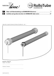
D Einbau- und Gebrauchsanleitung von RADEMACHER DuoFern-Rohrmotoren .......................................1<br />
EN Installation and operation instructions for RADEMACHER DuoFern tubular motors ...................... 27<br />
Gültig für die Serien: / Applicable for the following series: <strong>RolloTube</strong> I-<strong>line</strong> <strong>Sun</strong> <strong>Funk</strong> Medium / <strong>RolloTube</strong> I-<strong>line</strong> <strong>Sun</strong> Radio Medium (ILSFM ...)<br />
Bitte notieren: / Please note:<br />
Montageort: / Site of installation:<br />
.................................................................................................................................<br />
Seriennummer: / Serial number:<br />
.................................................................................................................................<br />
VBD 560-4-D-EN (06.11)
2<br />
i<br />
i<br />
i<br />
Sehr geehrte Kunden...<br />
...mit dem Kauf dieses Rohrmotors haben Sie sich für ein Qualitätsprodukt aus dem<br />
Hause RADEMACHER entschieden. Wir danken Ihnen für Ihr Vertrauen.<br />
Die RADEMACHER Rohrmotoren sind unter Aspekten des größten Komforts<br />
entstanden. Mit einem kompromisslosen Qualitätsanspruch und nach langen<br />
Versuchsreihen sind wir stolz, Ihnen dieses innovative Produkt zu präsentieren.<br />
Dahinter stehen alle hochqualifizierten<br />
Mitarbeiterinnen und Mitarbeiter aus<br />
dem Hause RADEMACHER.<br />
Diese Anleitung...<br />
...beschreibt Ihnen die Montage, den elektrischen Anschluss und die Bedienung<br />
von RADEMACHER DuoFern Rohrmotoren der Serie <strong>RolloTube</strong> I-<strong>line</strong> <strong>Sun</strong> <strong>Funk</strong><br />
Medium (ILSFM...).<br />
Bitte lesen Sie diese Anleitung vollständig durch und beachten Sie alle Sicherheitshinweise,<br />
bevor Sie mit den Arbeiten beginnen.<br />
Bitte bewahren Sie diese Anleitung auf und übergeben Sie die Anleitung bei einem<br />
Besitzerwechsel auch dem Nachbesitzer.<br />
Bei Schäden, die durch Nichtbeachtung dieser Anleitung und der Sicherheitshinweise<br />
entstehen, erlischt die Garantie. Für Folgeschäden, die daraus resultieren, übernehmen<br />
wir keine Haftung.<br />
Zeichenerklärung<br />
Lebensgefahr durch Stromschlag<br />
Dieses Zeichen weist Sie auf Gefahren bei Arbeiten an elektrischen Anschlüssen, Bauteilen<br />
etc. hin. Es fordert Sicherheitsmaßnahmen zum Schutz von Gesundheit und Leben der<br />
betroffenen Person.<br />
Hier geht es um Ihre Sicherheit.<br />
Beachten und befolgen Sie bitte alle so gekennzeichneten Hinweise.<br />
STOP<br />
D<br />
CE-Zeichen und Konformität<br />
Das vorliegende Produkt erfüllt die Anforderungen der geltenden europäischen und<br />
nationalen Richtlinien.<br />
Die Konformität wurde nachgewiesen. Die entsprechenden Erklärungen und Unterlagen<br />
sind beim Hersteller hinterlegt.<br />
So warnen wir vor Fehlverhalten, das zu Personen- oder Sachschäden<br />
führen kann.<br />
HINWEIS/WICHtIG/ACHtuNG<br />
Auf diese Weise machen wir Sie auf weitere für die einwandfreie <strong>Funk</strong>tion wichtige<br />
Inhalte aufmerksam.
1<br />
2 (8) (14) 3 (10) (16) 4<br />
5<br />
7<br />
3<br />
i Abbildungen<br />
(1)<br />
(2) (3) (4) (5) (6) (7) (8) (9) (10) (11) (12)<br />
(2) (3)<br />
(4)<br />
(3)<br />
(18)<br />
(2) (4) (5) (6) (7) (8) (9) (10)<br />
(13)<br />
(15) (10) (11) (6) (8) (11)<br />
(8) (7)<br />
(7) (1) (3)<br />
6<br />
8<br />
(4)<br />
(10)<br />
(17) (2)<br />
(19)<br />
D<br />
EN
4<br />
Legende der Gesamtansicht (Abbildung )<br />
(1) Seitenabdeckung<br />
(2) Montageschrauben<br />
(3) Lagerbock<br />
(4) Antriebslager (Click-Lager, Art.-Nr. 4015K-09)<br />
(5) Halteklammer<br />
(6) Antriebskopf<br />
(7) Setztaste<br />
(8) Adapter<br />
(9) Rohrmotor<br />
(10) Mitnehmer<br />
(11) Markisenwelle<br />
(12) Markisentuch<br />
(13) Motorkabel<br />
(14) Limitring<br />
(15) Rastbügel<br />
(16) Abtriebsadapter<br />
(17) Grundplatte des Antriebslagers<br />
(18) Quertraverse der Markise<br />
(19) Gelenkarme der Markise<br />
Vergleichen Sie nach dem Auspacken:<br />
◆ den Packungsinhalt mit den Angaben zum Lieferumfang auf der Verpackung.<br />
◆ den Motortyp mit den entsprechenden Angaben auf dem Typenschild.<br />
D
i<br />
Inhalt<br />
Sehr geehrte Kunden... .....................................................................................2<br />
Diese Anleitung... ............................................................................................2<br />
Zeichenerklärung .............................................................................................2<br />
Abbildungen ....................................................................................................3<br />
Legende der Gesamtansicht (Abbildung ) .....................................................4<br />
Allgemeine Sicherheitshinweise ..........................................................................6<br />
Richtige Verwendung / Einsatzbedingungen ........................................................6<br />
Falsche Verwendung ........................................................................................6<br />
<strong>Funk</strong>tion des <strong>Funk</strong>codes ....................................................................................6<br />
<strong>Funk</strong>tionsbeschreibung .....................................................................................7<br />
<strong>Funk</strong>tion der Tuchentlastung und der Blockiererkennung .........................................7<br />
<strong>Funk</strong>tion der Tuchstraffung und der Hinderniserkennung .........................................7<br />
Wichtige Montagehinweise ................................................................................8<br />
Vorbereitung der Markisenanlage .......................................................................8<br />
Montage/Demontage des Adapters (Abbildung 2) * ..........................................8<br />
Montage des Mitnehmers mit Freilauf (Abbildungen 3 und .a) * ........................9<br />
Montage des Mitnehmers ohne Freilauf (Abbildung .b ) ........................................9<br />
Demontage des Mitnehmers (Abbildung .c ) .......................................................9<br />
Den Rohrmotor in die Markisenwelle schieben (Abbildung 4) .............................10<br />
Vorbereitungen bei Verwendung von Präzisionsrohren (Abbildungen .a - .e ) ........10<br />
Montieren des Antriebslagers (Abbildung 5 - 7) ............................................12<br />
Die Markise für den elektrischen Anschluss und<br />
für die Inbetriebnahmen vorbereiten (Abbildung 8) ..........................................12<br />
Sicherheitshinweise zum elektrischen Anschluss ..................................................13<br />
Das Motorkabel (Abbildung i) ......................................................................13<br />
Elektrischer Anschluss des Rohrmotors (Abbildung j) ........................................14<br />
Steuerung mit 1poligem Taster (Schließer) (Abbildung k) .................................14<br />
Anschluss und Verwendung des Schnurschaltersetzgerätes<br />
zur Endpunkteinstellung (Abbildung l/m) ...................................................15<br />
Endpunkte einstellen ......................................................................................16<br />
Manuelle Einstellung der Endpunkte ..................................................................16<br />
Den oberen Endpunkt automatisch einstellen und den unteren manuell setzen ........17<br />
Oberen / unteren Endpunkt mit einem Schnurschaltersetzgerät oder<br />
mit einem externen Taster manuell einstellen .....................................................18<br />
Oberen / unteren Endpunkt mit Hilfe der<br />
Setztaste am Rohrmotor manuell einstellen .......................................................19<br />
Oberen / unteren Endpunkt mit DuoFern-Sendern einstellen ................................19<br />
Probelauf / Verändern der Endpunkte ...............................................................19<br />
Den Rohrmotor konfigurieren ...........................................................................20<br />
Die Werkseinstellungen bei der Inbetriebnahme laden .........................................20<br />
Was tun, wenn... ? ........................................................................................21<br />
Technische Daten ...........................................................................................22<br />
Verbinden/Trennen von DuoFern-Sendern ..........................................................23<br />
Einen DuoFern-Sender mit Hilfe der Setztaste verbinden/trennen ..........................23<br />
Die DuoFern-Handzentrale via <strong>Funk</strong>code verbinden/trennen .................................24<br />
EG-Konformitätserklärung ................................................................................26<br />
Garantiebedingungen......................................................................................26<br />
D<br />
5
6<br />
i<br />
i<br />
Allgemeine Sicherheitshinweise<br />
Bei allen Arbeiten an elektrischen Anlagen besteht Lebensgefahr durch<br />
Stromschlag.<br />
◆ Der Netzanschluss des Rohrmotors und alle Arbeiten an elektrischen Anlagen<br />
dürfen nur durch eine zugelassene Elektrofachkraft nach den Anschlussplänen<br />
in dieser Anleitung erfolgen (s. Seite 38/39/40).<br />
◆ Führen Sie alle Montage- und Anschlussarbeiten nur im spannungslosen Zustand<br />
aus.<br />
Der Einsatz defekter Geräte kann zur Gefährdung von Personen und<br />
zu Sachschäden führen (Stromschlag, Kurzschluss).<br />
◆ Verwenden Sie niemals defekte oder beschädigte Geräte.<br />
◆ Prüfen Sie Antrieb und Netzkabel auf Unversehrtheit.<br />
◆ Wenden Sie sich bitte an unseren Kundendienst (s. Seite 28), falls Sie Schäden<br />
am Gerät feststellen.<br />
Richtige Verwendung / Einsatzbedingungen<br />
Verwenden Sie die Rohrmotoren nur zum elektrischen Betrieb von<br />
von Markisen.<br />
WICHtIG<br />
◆ Das Motorkabel muss geschützt im Leerrohr unter Beachtung der örtlichen Elektrovorschriften<br />
bis zur Abzweigdose verlegt werden.<br />
◆ Verwenden Sie nur Original-Bauteile und -Zubehör des Herstellers.<br />
Verwenden Sie nur Rohrmotoren die in Ihrer Leistung den örtlichen<br />
Anforderungen entsprechen. Falsch dimensionierte Rohrmotoren können<br />
Schäden verursachen.<br />
◆ Lassen Sie sich bei der Auswahl eines Rohrmotors von einem Fachhändler beraten<br />
und beachten Sie die entsprechenden Zugkraftangaben auf unserer Homepage:<br />
www.rademacher.de<br />
Falsche Verwendung<br />
Die Verwendung des Rohrmotors zu anderen als den oben genannten<br />
Zwecken gilt als nicht bestimmungsgemäß.<br />
i <strong>Funk</strong>tion des <strong>Funk</strong>codes<br />
Mit Hilfe des <strong>Funk</strong>codes können Sie den <strong>Funk</strong>-Rohrmotor direkt ansteuern, um zum Beispiel<br />
auch nach der Installation weitere DuoFern-Geräte mit dem <strong>Funk</strong>-Rohrmotor zu verbinden.<br />
Nach einer erfolgreichen Verbindung können Sie zum Beispiel die Endanschläge eines<br />
<strong>Funk</strong>-Rohrmotors einstellen.<br />
Den <strong>Funk</strong>code finden Sie auf dem beiliegenden Etikett:<br />
Beispiel:<br />
D<br />
Bei unsachgemäßem Gebrauch besteht erhöhte Verletzungsgefahr.<br />
◆ Unterweisen Sie alle Personen im sicheren Gebrauch des Rohrmotors.<br />
◆ Verhindern Sie, dass Personen mit eingeschränkten Fähigkeiten sowie Kinder mit<br />
ortsfesten Steuerungen oder mit der Fernsteuerung spielen.<br />
◆ Beobachten Sie die sich bewegende Markise und halten Sie Personen fern, bis die<br />
Bewegung beendet ist.<br />
Bei Markisenanlagen, die außerhalb der Sichtweite betrieben werden<br />
können:<br />
◆ Die Markise nicht betreiben, wenn Arbeiten in der Nähe ausgeführt werden<br />
(z. B. Fenster putzen).<br />
Bei automatisch betriebenen Markisen:<br />
◆ Die Markise vom Versorgungsnetz trennen, wenn Arbeiten in der Nähe durchgeführt<br />
werden.<br />
Regelmäßige Wartung von Markisen erhöht die Betriebssicherheit.<br />
◆ Kontrollieren Sie die Markise regelmäßig auf mangelhafte Balance oder<br />
beschädigte Leitungen und Federn.<br />
◆ Lassen Sie beschädigte Markisen von einem Fachbetrieb instand setzen.<br />
Einsatzbedingungen<br />
◆ Für den elektrischen Anschluss muss am Einbauort ständig ein 230 V /50 Hz<br />
Stromanschluss mit bauseitiger Freischaltvorrichtung (Sicherung) vorhanden<br />
sein.<br />
◆ Der Einbau und der Betrieb des DuoFern-<strong>Funk</strong>systems und seiner Komponenten ist<br />
nur für solche Anlagen und Geräte zulässig, bei denen eine <strong>Funk</strong>tionsstörung im<br />
Sender oder Empfänger keine Gefahr für Personen oder Sachen ergibt oder bei denen<br />
dieses Risiko durch andere Sicherheitseinrichtungen abgedeckt wird.<br />
Verwenden Sie das DuoFern <strong>Funk</strong>system und seine Komponenten nie...<br />
...zur Fernsteuerung von Geräten und Anlagen mit erhöhten sicherheitstechnischen Anforderungen oder erhöhter<br />
Unfallgefahr. Dies bedarf zusätzlicher Sicherheitseinrichtungen. Beachten Sie die jeweiligen gesetzlichen<br />
Regelungen zum Errichten solcher Anlagen.<br />
HINWEIS<br />
Zeitfenster zur Aktivierung via <strong>Funk</strong>code.<br />
Nach dem Einschalten der Stromzufuhr ist der <strong>Funk</strong>code max. 2 Stunden lang aktiv.<br />
Nach Ablauf dieser Zeit ist eine Aktivierung mittels <strong>Funk</strong>code nicht mehr möglich. Trennen<br />
Sie den <strong>Funk</strong>-Rohrmotor kurzzeitig vom Netz, um das Zeitfenster erneut zu aktivieren.
i<br />
i<br />
i<br />
<strong>Funk</strong>tionsbeschreibung<br />
Die RADEMACHER DuoFern Rohrmotoren <strong>RolloTube</strong> I-<strong>line</strong> <strong>Sun</strong> <strong>Funk</strong> (ILSFM...) dienen zum<br />
elektrischen Betrieb (Ein-/Ausfahren) von Markisen.<br />
Durch die interne DuoFern-Schnittstelle können Sie den Motor in ein DuoFern-<strong>Funk</strong>netzwerk<br />
integrieren und so viele Automatikfunktionen mit Hilfe eines DuoFern-Senders (z.B. mit<br />
der DuoFern-Handzentrale) einstellen und fernsteueren.<br />
Zur manuellen Bedienung vor Ort können Sie zusätzlich einen externen Taster an den<br />
Rohrmotor anschließen.<br />
Die <strong>RolloTube</strong> I-<strong>line</strong> <strong>Sun</strong> <strong>Funk</strong> Rohrmotoren sind mit dem neuen Safe-Drive-Verfahren zur<br />
Positionserfassung, Drehmomentüberwachung und Hinderniserkennung ausgestattet. Die<br />
kompakte Bauweise und eine Endpunkteinstellung des Antriebs sorgen für eine einfache,<br />
komfortable Montage.<br />
Im täglichen Betrieb überzeugt der <strong>RolloTube</strong> I-<strong>line</strong> <strong>Sun</strong> <strong>Funk</strong> durch die automatische<br />
Tuchentlastung und Tuchstraffung (mit Reversierung) für höchste Sicherheit und einen<br />
tuchschonenden Lauf.<br />
<strong>Funk</strong>tionsübersicht:<br />
Allgemeine Rohrmotor-<strong>Funk</strong>tionen:<br />
◆ Inbetriebnahme mit einem Fahrbefehl. Selbstlernender Motor mit automatischer<br />
Endpunkteinstellung des oberen Endpunktes.<br />
◆ Safe-Drive-Verfahren zur exakten Positionserfassung, Drehmomentüberwachung und<br />
Hinderniserkennung.<br />
◆ Blockier- und Hinderniserkennung sowie eine integrierte Tuchentlastung und Tuchstraffung,<br />
inklusive Reversierung.<br />
◆ Durch das neue rastende FlexiClick-Prinzip ist die Hinderniserkennung frei wählbar.<br />
◆ Einfacher und schneller Einbau durch die kurze Bauform.<br />
◆ Optional erhältlich: Universelles RT ConfigTool zur individuellen Anpassung der<br />
Motorparameter.<br />
Kurzbeschreibung des DuoFern <strong>Funk</strong>systems<br />
Mit dem DuoFern <strong>Funk</strong>system ist ein bi-direktionaler Datenaustausch zwischen den<br />
verschiedenen Teilnehmern eines DuoFern-<strong>Funk</strong>netzwerks möglich. Alle Schaltbefehle eines<br />
DuoFern-Senders (z. B. DuoFern Handzentrale) werden von den DuoFern-Komponenten<br />
(Aktoren/Sensoren) empfangen und bestätigt, sofern beide miteinander verbunden sind.<br />
<strong>Funk</strong>tion der tuchentlastung und der Blockiererkennung<br />
<strong>Funk</strong>tion bei Störung bzw. bei Blockierung der Markise:<br />
Der Rohrmotor stoppt und entlastet automatisch das Markisentuch durch ein kurzes Anfahren<br />
in die Gegenrichtung (Reversieren), falls die Markise beim Einfahren durch ein Hindernis<br />
blockiert wird.<br />
HINWEIS<br />
Eine blockierte Markise darf nicht bewegt werden, bevor die Störung bzw. das Hindernis<br />
beseitigt wurde.<br />
<strong>Funk</strong>tion der tuchstraffung und der Hinderniserkennung<br />
<strong>Funk</strong>tion der Hinderniserkennung beim Ausfahren der Markise:<br />
Der Rohrmotor stoppt und fährt automatisch kurz in die Gegenrichtung, falls die Markise<br />
beim Ausfahren auf ein Hindernis stößt.<br />
Bedingungen für die korrekte <strong>Funk</strong>tion der Hinderniserkennung:<br />
◆ Der Mitnehmer (10) muss mit Freilauf montiert sein (s. Abb. .a; Seite 34).<br />
Rohrmotorfunktionen in Verbindung mit DuoFern-Sendern<br />
Automatische tuchentlastung während des Normalbetriebs:<br />
D<br />
DuoFern umweltsensor Art.-Nr. 9475<br />
DuoFern Handzentrale Art.-Nr. 9493<br />
Rollotron Pro Comfort DuoFern Art.-Nr. 980x<br />
DuoFern Handsender Standard Art.-Nr. 9491-x<br />
DuoFern Wandtaster Art.-Nr. 9494-xx<br />
Manuelle Bedienung (auf/stopp/ab) ● ● ● ●<br />
Zufallsfunktion ● ●<br />
Manuellbetrieb (ein/aus) ● ●<br />
Zeitautomatik (ein/aus) ● ●<br />
Sonnenautomatik (ein/aus) ● ●<br />
Sonnenprogramm ● ●<br />
Morgendämmerungsautomatik (ein/aus) ● ●<br />
Morgendämmerungsfunktion ● ●<br />
Abenddämmerungsautomatik (ein/aus) ● ●<br />
Abenddämmerungsfunktion ● ● ●<br />
Windautomatik (ein/aus)<br />
●<br />
Windfunktion<br />
●<br />
Drehrichtung Wind<br />
●<br />
Regenautomatik (ein/aus)<br />
●<br />
Regenfunktion<br />
●<br />
Drehrichtung Regen<br />
●<br />
Lüftungsposition<br />
●<br />
Drehrichtungsumkehr ● ● ●<br />
Verbindungstest ● ●<br />
Endpunkteinstellung per <strong>Funk</strong> ● ●<br />
<strong>Funk</strong>code<br />
●<br />
Während des Normalbetriebs fährt die Markise gegen den oberen Endpunkt und<br />
anschließend kurz in die Gegenrichtung (Reversieren) um das Markisentuch automatisch<br />
zu entlasten.<br />
HINWEIS<br />
Diese <strong>Funk</strong>tion ist nur aktiv wenn der obere Endpunkt automatisch eingestellt wurde,<br />
s. Seite 42.<br />
Automatische tuchstraffung während des Normalbetriebs:<br />
Während des Normalbetriebs fährt die Markise gegen den unteren Endpunkt und anschließend<br />
kurz in die Gegenrichtung (Reversieren), um das Markisentuch automatisch<br />
zu straffen.<br />
HINWEIS<br />
Diese <strong>Funk</strong>tion ist nur aktiv, wenn der obere Endpunkt automatisch eingestellt wurde,<br />
s. Seite 42.<br />
7
8<br />
STOP<br />
Wichtige Montagehinweise<br />
Durch die falsche Montage der Markise besteht eine hohe Verletzungsgefahr.<br />
Lassen Sie alle Montage- und Reparaturarbeiten an der Markisenanlage<br />
nur durch einen Fachbetrieb ausführen.<br />
Prüfen Sie, ... :<br />
◆ ... ob die Markise für den Einbau des Rohrmotors geeignet ist.<br />
◆ ... ob der Rohrmotor ausreichend dimensioniert ist.<br />
◆ ... ob der bauliche Untergrund für den Betrieb einer elektrisch angetriebenen<br />
Markise ausreichend stabil ist.<br />
WICHtIG<br />
◆ Vergleichen Sie vor der Montage die Angaben zur Spannung/Frequenz auf dem<br />
Typenschild mit denen des örtlichen Netzes.<br />
◆ Vor dem Einbau des Rohrmotors alle nicht zum Betrieb benötigten Leitungen<br />
und Einrichtungen abbauen bzw. außer Betrieb setzen.<br />
◆ Bewegliche Teile von Antrieben, die unter einer Höhe von 2,5 m vom Boden<br />
betrieben werden, müssen geschützt werden.<br />
◆ Wird der Rohrmotor mit einem Schalter mit AUS-Voreinstellung gesteuert, ist<br />
dieser Schalter in Sichtweite des Rohrmotors von sich bewegenden Teilen entfernt<br />
in mindestens 1,5 m Höhe anzubringen.<br />
◆ Die Setztaste (7) des Rohrmotors muss später leicht zugänglich sein und das Motorkabel<br />
(13) muss ohne Knick verlegt werden.<br />
Bei automatisch betriebenen Markisen:<br />
◆ Bei Markisen ist der Mindestabstand von 0,4 m zu den Teilen in der Umgebung<br />
bei voll ausgerollter Markise zu beachten.<br />
◆ Bei Einsatz in Markisenanlagen darf der unterste Punkt der Markise 1,8 m<br />
nicht unterschreiten.<br />
Vorbereitung der Markisenanlage<br />
Durch herabfallende Gelenkarme (19) besteht Verletzungsgefahr. Die<br />
Gelenkarme (19) sitzen unter hoher Federspannung und können beim<br />
Lösen des Markisengetriebes plötzlich herunterfallen.<br />
◆ Fahren Sie die Markise vollständig ein und sichern Sie die Gelenkarme (19) vor dem<br />
Einbau des Rohrmotors mit zwei Spanngurten gegen plötzliches Herunterfallen.<br />
HINWEIS<br />
Auf Grund der verschiedenen Markisenmodelle müssen Sie die Vorbereitungen auf die am<br />
Einbauort vorhandene Markisenanlage abstimmen. Im Folgenden beschreiben wir Ihnen<br />
daher allgemein die wichtigsten Schritte für die Vorbereitung einer Markisenanlage zur<br />
Montage des <strong>RolloTube</strong> I-<strong>line</strong> <strong>Sun</strong> <strong>Funk</strong> Rohrmotors.<br />
STOP<br />
Montage/Demontage des Adapters (Abbildung 2) *<br />
* = Im Auslieferungszustand ist der Adapter schon ab Werk vormontiert.<br />
1. Montage des Adapters (8)<br />
Schieben Sie den Adapter (8) über den Limitring (14) am Antriebskopf<br />
bis er einrastet. Achten Sie dabei auf die richtige Lage der Nut im<br />
Adapter (8).<br />
1.<br />
2.<br />
3.<br />
D<br />
Durch direkten Wettereinfluss auf den ungeschützten Rohrmotor besteht<br />
Kurzschluss- und Brandgefahr.<br />
Der montierte Rohrmotor darf niemals direktem Regen oder Schneefall<br />
ausgesetzt sein, das kann zu lebensgefährlichen Situationen durch<br />
Kurzschlüsse und zu seiner Zerstörung führen.<br />
◆ Montieren Sie den Rohrmotor nur in Markisenanlagen, in denen ein baulicher Schutz<br />
vor direktem Regen oder Schneefall für den Motor besteht.<br />
◆ Montieren Sie, falls erforderlich, eine entsprechende Schutzhaube für den Rohrmotor<br />
Bei Arbeiten in größeren Höhen besteht Verletzungsgefahr durch<br />
Absturz.<br />
◆ Treffen Sie geeignete Maßnamen zum sicheren Arbeiten in größeren Höhen.<br />
◆ Achten Sie auf einen sicheren Stand von Leitern oder Gerüsten.<br />
Fahren Sie die Markise vollständig ein.<br />
Nie im Bereich des Antriebs bohren<br />
oder schrauben. Das führt zur Zerstörung<br />
des Rohrmotors.<br />
Sichern Sie die Gelenkarme (19) mit Spanngurten gegen plötzliches<br />
Herunterfallen.<br />
Bauen Sie das Markisengetriebe aus.<br />
2. Demontage des Adapters (8)<br />
Drücken Sie beide Haltefedern am Limitring (14) nach unten und ziehen<br />
Sie den Adapter (8) vom Limitring (14) ab.
Montage des Mitnehmers mit Freilauf (Abbildungen 3 und .a) *<br />
* = Im Auslieferungszustand ist der Mitnehmer schon ab Werk vormontiert.<br />
3.a (10)<br />
(16)<br />
3.b<br />
3.c<br />
(10)<br />
(15)<br />
(10)<br />
(15)<br />
Montage des Mitnehmers ohne Freilauf (Abbildung .b )<br />
(16)<br />
Demontage des Mitnehmers (Abbildung .c )<br />
(16)<br />
1.<br />
1.<br />
1.<br />
D<br />
WICHtIG<br />
Soll der Rohrmotor mit der Hinderniserkennung arbeiten, müssen Sie<br />
den Mitnehmer (10) mit Freilauf montieren.<br />
Schieben Sie den Mitnehmer (10) so auf den Abtriebsadapter (16), dass<br />
er Freilauf hat und hinter dem Rastbügel (15) einrastet.<br />
Im Freilauf lässt sich der Mitnehmer (10) leicht hin- und herdrehen.<br />
WICHtIG<br />
Das Montieren des Mitnehmers (10) ohne Freilauf kann notwendig<br />
sein, um bei Markisen mit sehr geringem Eigengewicht oder bei schlecht<br />
laufenden Markisen ein vorzeitiges Abschalten zu vermeiden.<br />
Schieben Sie den Mitnehmer (10) so auf den Abtriebsadapter (16),<br />
dass er keinen Freilauf hat und hinter dem Rastbügel (15) einrastet.<br />
HINWEIS<br />
◆ Wird der Mitnehmer (10) ohne Freilauf montiert, arbeitet der Rohrmotor<br />
ohne Hinderniserkennung.<br />
Drücken Sie die Seitenteile des Rastbügels (15) zusammen und ziehen<br />
die den Mitnehmer (10) vom Abtriebsadapter (16) ab.<br />
9
1.<br />
10<br />
STOP<br />
Den Rohrmotor in die Markisenwelle schieben (Abbildung 4)<br />
4.a<br />
4.b<br />
1<br />
Schlagen Sie nie den Motor (9) mit<br />
Gewalt in die Markisenwelle (11) ein.<br />
Das führt zu seiner Zerstörung.<br />
Schieben Sie zuerst den Mitnehmer (10) in die Markisenwelle (11). 2. Drücken Sie anschließend den Rohrmotor so in die Markisenwelle (11),<br />
dass der Adapter (8) vollständig in der Markisenwelle (11) steckt.<br />
WICHtIG<br />
Achten Sie darauf, dass der Adapter (8) während der Montage nicht vom Limitring (14)<br />
am Antriebskopf (6) abrutscht. Es kommt sonst zu Fehlfunktionen, s. Seite 46.<br />
Vorbereitungen bei Verwendung von Präzisionsrohren (Abbildungen .a - .e )<br />
WICHtIG<br />
◆ Bitte verwenden Sie ausschließlich Präzisionsrohre aus Aluminium.<br />
4.c<br />
ALuMINIuM<br />
Rollotube I-<strong>line</strong> <strong>Sun</strong> <strong>Funk</strong> Medium (ILSFM...)<br />
<br />
1. Messen Sie den Abstand zwischen Adapter (8) und dem hinteren<br />
Drittel des Mitnehmers (10) und zeichnen Sie diesen Abstand auf das<br />
Präzisionsrohr.<br />
2. Sägen Sie am Ende des Präzisionsrohrs eine Nut 1 aus, damit der Nocken<br />
des Adapters (8) ganz in das Rohr geschoben werden kann.<br />
HINWEIS<br />
◆ Zwischen der Nut 1 und dem Nocken darf kein Spiel vorhanden sein.<br />
3. Den Rohrmotor (9) in das Präzisionsrohr schieben.<br />
D<br />
WICHtIG<br />
Die Setztaste (7) des Rohrmotors muss später leicht zugänglich sein und das Motorkabel<br />
(13) muss ohne Knick verlegt werden.
Vorbereitungen bei Verwendung von Präzisionsrohren (Abbildungen .a - .e )<br />
4.d<br />
4.e<br />
STOP<br />
4. Markieren Sie vier Befestigungslöcher und bohren Sie diese anschließend<br />
durch das Präzisionsrohr in den Mitnehmer (10).<br />
ACHtuNG<br />
◆ Bohren Sie nie tiefer als 10 mm in den Mitnehmer (10).<br />
◆ Nie im Bereich des Antriebs bohren. Das führt zu seiner Zerstörung.<br />
5.<br />
D<br />
Das Präzisionsrohr am Mitnehmer (10) festschrauben oder vernieten.<br />
Verwenden Sie vier selbstschneidende Blechschrauben, Kunststoffschrauben oder vier<br />
Blindnieten.<br />
11
1.<br />
12<br />
Montieren des Antriebslagers (Abbildung 5 - 7)<br />
Schrauben Sie das Antriebslager (4) am zuvor ausgebauten Lagerbock<br />
(3) fest (s. Abbildung 5).<br />
WICHtIG<br />
Montieren Sie das Antriebslager (4) so auf dem Lagerbock (3), dass die Setztaste (7)<br />
des Rohrmotors (9) immer gut zugänglich ist.<br />
Bei Verwendung zu langer Montageschrauben kann das Antriebslager<br />
(4) verbogen bzw. zerstört werden (s. Abbildung 6) und unten.<br />
Die Montageschrauben (2) müssen bündig mit der Grundplatte (17) abschließen, sonst<br />
kann das Antriebslager (4) verbogen und von der Grundplatte (17) abgedrückt werden.<br />
Das gilt besonders bei Verwendung der inneren Montagelöcher auf der Grundplatte (17).<br />
(17) (2)<br />
Die Markise für den elektrischen Anschluss und<br />
für die Inbetriebnahmen vorbereiten (Abbildung 8)<br />
1. Setzen Sie zum Schluss die Seitenabdeckung (1) (falls vorhanden) wieder<br />
auf den Lagerbock (3), (s. Abbildung 8).<br />
2. Lösen Sie die Spanngurte wieder von den Gelenkarmen.<br />
3.<br />
Antriebslager (als Clicklager)<br />
Überprüfen Sie abschließend noch einmal die Montagearbeiten auf ihre<br />
korrekte Ausführung.<br />
2.<br />
3.<br />
4.<br />
Antriebslager (alle anderen Lagervarianten)<br />
D<br />
Schieben Sie anschließend den Lagerbock (3) wieder auf die Quertraverse<br />
(18) der Markise bis das Antriebslager (4) vollständig am<br />
Antriebskopf (6) einrastet (s. Abbildung 7).<br />
Prüfen Sie, ob die Setztaste (7) des Motors (9) frei zugänglich ist.<br />
Korrigieren Sie gegebenenfalls die Position des Antriebslagers (4) am<br />
Lagerbock (3).<br />
HINWEIS<br />
Der Rohrmotor kann in vier Stellungen in das Clicklager (4) eingebaut werden.<br />
Durch Spreizen der Halteklammer (5) können Sie den Motor jederzeit wieder aus dem<br />
Clicklager (4) lösen.<br />
Schrauben Sie zum Schluss den Lagerbock (3) wieder an der Quertraverse<br />
(18) der Markise fest.<br />
Die Montage mit anderen Lagervarianten erfolgt analog zu der vorangegangenen Beschreibung.<br />
Beachten Sie dabei jeweils die Besonderheiten des jeweiligen Lagertyps, z. B. die<br />
Verbindung zwischen Antriebskopf und Antriebslager mit einem Splint .
Sicherheitshinweise zum elektrischen Anschluss<br />
Bei allen Arbeiten an elektrischen Anlagen besteht Lebensgefahr durch<br />
Stromschlag.<br />
◆ Der Netzanschluss des Rohrmotors und alle Arbeiten an elektrischen Anlagen<br />
dürfen nur durch eine zugelassene Elektrofachkraft nach den Anschlussplänen<br />
in dieser Anleitung erfolgen.<br />
◆ Trennen Sie die Zuleitung allpolig vom Netz und sichern Sie sie gegen unbeabsichtigtes<br />
Einschalten.<br />
◆ Prüfen Sie die Anlage auf Spannungsfreiheit.<br />
◆ Führen Sie alle Montage- und Anschlussarbeiten nur im spannungslosen Zustand aus<br />
Kurzschlussgefahr durch beschädigte Kabel.<br />
◆ Verlegen Sie alle Motorkabel (13) so, dass diese nicht durch bewegliche Teile der<br />
Markise beschädigt werden können.<br />
◆ Verlegen Sie das Motorkabel (13) im Leerrohr bis zur Wanddurchführung.<br />
◆ Dichten Sie die Wanddurchführung nach dem Verlegen des Motorkabels (13) gegen<br />
das Eindringen von Wasser ab.<br />
◆ Die Netzanschlussleitung dieses Antriebs darf nur durch den gleichen Leitungstyp<br />
angeschlossen werden. Wenden Sie sich ggf. an den Kundendienst.<br />
Das Motorkabel (Abbildung i)<br />
9<br />
(7)<br />
(13)<br />
ext. taster<br />
L<br />
N<br />
PE<br />
STOP<br />
D<br />
Bei festinstallierten Geräten...<br />
...muss gemäß DIN VDE 0700 installationsseitig eine Trennvorrichtung für jede Phase<br />
vorhanden sein. Als Trennvorrichtung gelten Schalter mit einer Kontaktöffnungsweite von<br />
min. 3 mm (z. B. LS-Schalter, Sicherungen od. FI-Schalter).<br />
Kurzschlussgefahr durch Wasser bei falscher Kabelführung.<br />
Verlegen Sie das Motorkabel (13) nie direkt senkrecht nach oben, sonst kann evtl.<br />
Wasser über das Kabel in den Motor laufen und diesen zerstören. Verlegen Sie das Kabel<br />
in einer Schlaufe. Die Schlaufe bewirkt, dass am Kabel ablaufendes Wasser am tiefsten<br />
Punkt der Schlaufe gesammelt wird und dort abtropft.<br />
1. Führen Sie das Motorkabel (13) nach der Montage des Motors in<br />
die dafür vorgesehene Abzweig- oder Schalterdose.<br />
Farbskala des Motorkabels (13)<br />
◆ = externer Taster (weiß)<br />
L = Phase (schwarz)<br />
N = Neutralleiter (blau)<br />
PE = Erdung (grün/gelb)<br />
◆ = Antenne (violett)<br />
(7) =<br />
Die Antenne befindet sich bündig im Kabel.<br />
Setztaste am Rohrmotor<br />
13
14<br />
Elektrischer Anschluss des Rohrmotors (Abbildung j)<br />
10<br />
(a)<br />
(b)<br />
(c)<br />
11 (a)<br />
(b)<br />
(c)<br />
(d)<br />
(d)<br />
(e) (f) (g) (h) (i)<br />
(e) (f) (g) (h) (i)<br />
Legende<br />
(a) = Setztaste (7)<br />
(b/d) = Schalterdose<br />
(c) = Netz 230 V/50 Hz<br />
Steuerung mit 1poligem taster (Schließer) (Abbildung k)<br />
Durch den Anschluss eines 1poligen Tasters (Schließer) an die Leitung „externer<br />
taster“, kann der <strong>Funk</strong>-Rohrmotor vor Ort manuell gesteuert werden.<br />
Die Schaltreihenfolge ist dabei wie folgt:<br />
Einfahren/Stopp/Ausfahren/Stopp/...<br />
Anschlussbelegung<br />
(e) = PE grün/gelb<br />
(f) = N blau<br />
(g) = L schwarz<br />
(h) = externer taster weiß (wird in diesem Beispiel nicht verwendet)<br />
(i) = Antenne violett<br />
D<br />
WICHtIG<br />
◆ Falls die Leitung „externer taster“ (h) nicht verwendet wird, muss sie am<br />
Neutralleiter (f) angeschlossen werden (s. Abbildung j).<br />
Legende<br />
(a) = Setztaste (7)<br />
(b) = 1poliger Taster<br />
(c) = Netz 230 V/50 Hz<br />
(d) = Schalterdose<br />
Anschlussbelegung<br />
(e) = PE grün/gelb<br />
(f) = N blau<br />
(g) = L schwarz<br />
(h) = externer taster weiß *<br />
(i) = Antenne violett<br />
* maximale Kabellänge zwischen Rohrmotor und externem Taster = 10 m<br />
WICHtIG<br />
◆ Falls die Leitung „externer taster“ (h) nicht verwendet wird, muss sie am<br />
Neutralleiter (f) angeschlossen werden (s. Abbildung j).
Anschluss und Verwendung des Schnurschaltersetzgerätes<br />
zur Endpunkteinstellung (Abbildung l/m)<br />
12<br />
13<br />
(20)<br />
Hebel<br />
ON<br />
ON<br />
SEt<br />
D<br />
Bei einer Erstinstallation kann der Monteur das Motorkabel (13) an ein im Fachhandel<br />
erhältliches Schnurschaltersetzgerät (20) (Art. Nr. 4090) anschließen, um damit die<br />
Endpunkte Ihres Rohrmotors einzustellen.<br />
Führen Sie dazu nach der Montage die Leitungen (e - h) des Motorkabels (13) bis<br />
zur jeweiligen Schaltstelle (z. B. bis in die Schalterdose).<br />
Verwendung der Leitung „externer taster“ (h).<br />
Wenn Sie die Leitung „externer taster“ (h) des Motorkabels (13) an die „SEttaste“<br />
des Schurschaltersetzgerätes (20) anschließen, können Sie diese als Setztaste<br />
zur Einstellung der Endpunkte nutzen.<br />
HINWEIS<br />
Beachten Sie die verschiedenen Einstellmöglichkeiten für die Endpunkte im Kapitel<br />
„Endpunkte einstellen“ (s. unten) und auf den folgenden Seiten.<br />
Öffnen Sie die Klemmkontakte durch Drücken der Hebel und klemmen<br />
Sie alle Adern des Motorkabels (13) wie folgt an:<br />
Motorkabel > Schnurschaltersetzgerät<br />
<strong>Funk</strong>tion > <strong>Funk</strong>tion<br />
L > L1 (Drehrichtung 1)<br />
Externer taster > Setzleitung<br />
N > N<br />
PE > PE<br />
Nach dem Anschluss haben die tasten des Schnurschaltersetzgerätes<br />
(20) folgende <strong>Funk</strong>tionen:<br />
Schaltwippe in Mittelstellung = Motorspannung aus<br />
Schaltwippe in Auf (s)-Stellung = Motorspannung ein<br />
SEt-taste = Setztaste = Markise Einfahren/Stopp/Ausfahren/<br />
Stopp/...<br />
WICHtIG<br />
Die Leitung „externer taster“ (h) muss nach Einstellung der Endpunkte<br />
am Neutralleiter (f) angeschlossen werden (s. Abbildung j).<br />
15
16<br />
Endpunkte einstellen<br />
Lebensgefahr durch Abreißen des Motorkabels (13).<br />
Achten Sie darauf, dass das Motorkabel (13) während der Einstellungen nicht durch<br />
die Markisenwelle (11) erfasst bzw. abgerissen wird.<br />
Sie haben verschiedene Möglichkeiten zur Einstellung der Endpunkte,<br />
die wir Ihnen im Folgenden beschreiben:<br />
◆ Den oberen Endpunkt automatisch (mit Hilfe der Blockiererkennung) einstellen und<br />
den unteren Endpunkt manuell setzen.<br />
◆ Den oberen/unteren Endpunkt manuell einstellen.<br />
Wichtiger Zusammenhang zwischen der Hinderniserkennung und der<br />
Montage des Mitnehmers mit oder ohne Freilauf.<br />
◆ Wird der Mitnehmer ohne Freilauf montiert, schaltet der Rohrmotor nicht automatisch<br />
ab, da er kein Hindernis erkennt.<br />
◆ Wird der Mitnehmer mit Freilauf montiert, schaltet der Rohrmotor beim Ausfahren<br />
der Markise erst dann automatisch ab, sobald der Mitnehmer den Freilauf überwunden<br />
hat.<br />
Manuelle Einstellung der Endpunkte<br />
Erstinstallation<br />
Bei einer Erstinstallation kann der Monteur die Einstellung der Endpunkte mit<br />
Hilfe der Setztaste (7) am Motor (9) oder mit einem im Fachhandel erhältlichen<br />
Schnurschaltersetzgerät (20) vornehmen. Bitte beachten Sie die Sicherheitshinweise<br />
in der <strong>Bedienungsanleitung</strong> des Schnurschaltersetzgerätes.<br />
Nachträgliche Änderung der Endpunkte mit externen Steuerungen<br />
Wollen Sie nachträglich die Endpunkte Ihres Rohrmotors verändern, können Sie,<br />
wie zuvor gezeigt, mit einem externen taster als Setztaste oder mit Ihrer<br />
Rohrmotorsteuerung die Endpunkte neu einstellen.<br />
STOP<br />
D<br />
WICHtIG<br />
◆ Sie müssen für beide Laufrichtungen, Auf (s)/Ab (▼), Endpunkte setzen, bei<br />
deren Erreichen der Motor abschaltet.<br />
◆ Der Rohrmotor muss vollständig eingebaut sein.<br />
◆ Die Setztaste (7) am Rohrmotor muss frei zugänglich sein.<br />
◆ Klemmen Sie das Schnurschaltersetzgerät (20) nach den Endpunkteinstellungen<br />
wieder ab und schließen Sie den Rohrmotor gemäß dem<br />
Anschlussplan j an.<br />
◆ Die Leitung „externer taster“ (h) muss nach Einstellung der Endpunkte<br />
am Neutralleiter (f) angeschlossen werden (s. Abbildung j).<br />
Während der Einstellungen besteht Verletzungsgefahr durch Quetschen<br />
der Hand an der sich bewegenden Markise.<br />
Greifen Sie nie bei laufendem Motor in den Bereich der Markisenwelle bzw. in die<br />
Gelenkarme.
2.<br />
4.<br />
5.<br />
6.<br />
Den oberen Endpunkt automatisch einstellen und den unteren manuell setzen<br />
1. ON<br />
Die Netzspannung einschalten.<br />
oder<br />
EIN<br />
3.<br />
7.<br />
SEt oder<br />
oder AuS<br />
Symbole und Handlungen bei Anschluss eines Schnurschaltersetzgerätes (20)<br />
oder<br />
bei Anschluss eines externen tasters.<br />
Die Markise vollständig einfahren und gegen den oberen Anschlag fahren, bis der Rohrmotor automatisch stoppt.<br />
Falls der Rohrmotor schon im DuoFern-Netzwerk angemeldet wurde, kann die Fahrtrichtung auch mit DuoFern-Sendern vorgegeben werden.<br />
WICHtIG<br />
◆ Greifen Sie während der Fahrt nicht in den Ablauf ein. Die Markise muss ohne Unterbrechung einfahren.<br />
◆ Die Markise muss zuerst einfahren. Falls die Markise zuerst ausfährt, müssen Sie durch mehrfaches Drücken der<br />
SEt-taste oder des externen tasters die Markise stoppen und die Fahrtrichtung umkehren.<br />
◆ Die Schaltreihenfolge der SEt-taste oder des externen tasters ist: Einfahren/Stopp/Ausfahren/Stopp...<br />
Anschließend fährt der Rohrmotor die Markise automatisch in die Gegenrichtung.<br />
Die Setztaste (7) am Rohrmotor drücken und festhalten, bis der untere Endpunkt erreicht ist.<br />
Die Setztaste (7) sofort loslassen, wenn die Markise die gewünschte Position erreicht hat.<br />
Der Motor stoppt und beide Endpunkte sind gespeichert.<br />
Durch kurzes tippen der Setztaste (7) können Sie den unteren Endpunkt in kleinen Schritten korrigieren.<br />
WICHtIG<br />
◆ Kommt es während der Einstellungen zu einer Fehlfunktion, läuft z. B. der Rohrmotor nur eine Umdrehung lang, auch beim Drücken<br />
der Setztaste, ist Ihr Rohrmotor wahrscheinlich nicht defekt, eventuell ist der Adapter (8) vom Antriebskopf (6) abgerutscht.<br />
◆ Prüfen und korrigieren Sie ggf. den richtigen Sitz des Adapters (8), (s. Seite 46).<br />
HINWEIS<br />
Falls diese Einstellung der Endpunkte fehlschlägt, müssen Sie den Rohrmotor auf die Werkseinstellungen zurücksetzen (s. Seite 45), um den<br />
Vorgang zu wiederholen.<br />
Schalten Sie zum Schluss den Rohrmotor für einige Sekunden stromlos. Danach ist der Rohrmotor betriebsbereit<br />
HINWEIS<br />
Nur wenn die Endpunkte wie oben beschrieben eingestellt wurden, sind die Tuchentlastung und die Tuchspannung aktiv.<br />
WICHtIG<br />
◆ Die Leitung „externer taster“ (h) muss nach Einstellung der Endpunkte am Neutralleiter (f) angeschlossen werden .<br />
D<br />
17
1.<br />
2.<br />
3.<br />
4.<br />
5.<br />
6.<br />
7.<br />
18<br />
Oberen / unteren Endpunkt mit einem Schnurschaltersetzgerät oder<br />
mit einem externen taster manuell einstellen<br />
SEt<br />
SEt +<br />
SEt<br />
SEt<br />
ON<br />
oder<br />
oder<br />
oder +<br />
oder<br />
oder<br />
oder<br />
AuS<br />
AuS<br />
EIN<br />
Symbole und Handlungen bei Anschluss eines Schnurschaltersetzgerätes (20)<br />
oder<br />
bei Anschluss eines externen tasters.<br />
Die Netzspannung ausschalten.<br />
Bei Verwendung eines Schnurschaltersetzgerätes (20) muss dazu die Schaltwippe in der Mittelstellung stehen.<br />
SEt-taste oder externen taster drücken und gedrückt halten.<br />
Zusätzlich die Netzspannung einschalten.<br />
Nach ca. 6 Sekunden läuft der Rohrmotor an und die Markise fährt ein oder aus.<br />
Die SEt-taste sofort loslassen, wenn die Markise die gewünschte Position erreicht hat.<br />
Der Motor stoppt und der erste Endpunkt ist gespeichert.<br />
Durch kurzes tippen der SEt-taste, können Sie den Endpunkt in kleinen Schritten korrigieren.<br />
WICHtIG<br />
Kommt es während der Einstellungen zu einer Fehlfunktion, läuft z.B. der Rohrmotor nur eine Umdrehung lang, auch beim Drücken der<br />
SET-Taste, ist Ihr Rohrmotor wahrscheinlich nicht defekt, eventuell ist der Adapter (8) vom Motorkopf abgerutscht.<br />
Prüfen und korrigieren Sie ggf. den richtigen Sitz des Adapters (8), (s. Seite 46).<br />
HINWEIS<br />
Auch bei einem Stromausfall bleiben die Endpunkte dauerhaft erhalten.<br />
Die Netzspannung wieder ausschalten.<br />
Wiederholen Sie die Punkte 2. bis 5. für den zweiten Endpunkt.<br />
WICHtIG<br />
◆ Die Leitung „externer taster“ (h) muss nach Einstellung der Endpunkte am Neutralleiter (f) angeschlossen werden .<br />
◆ Nach einer manuellen Einstellung der Endpunkte ist die <strong>Funk</strong>tion „tuchstraffung“ deaktiviert.<br />
D
1.<br />
2.<br />
3.<br />
4.<br />
5.<br />
Oberen / unteren Endpunkt mit Hilfe der<br />
Setztaste am Rohrmotor manuell einstellen<br />
ON<br />
oder<br />
SEt oder<br />
EIN<br />
Probelauf / Verändern der Endpunkte<br />
Kontrollieren Sie Ihre Einstellungen und lassen Sie die Markise in<br />
beide Richtungen laufen, bis die Endpunkte den Motor ausschalten.<br />
thermoschutz<br />
Die Rohrmotoren sind für den Kurzzeitbetrieb (ca. 4 Min.) ausgelegt.<br />
Das Überschreiten dieser Zeit oder häufiges Umschalten führen zur Erwärmung<br />
des Motors und zur Abschaltung durch den Thermoschutz.<br />
Lassen Sie den Motor in diesem Fall 20 Minuten abkühlen.<br />
Symbole und Handlungen bei Anschluss eines Schnurschaltersetzgerätes (20)<br />
oder<br />
bei Anschluss eines externen tasters.<br />
Die Netzspannung einschalten.<br />
Die Markise in die gewünschte Laufrichtung schalten, beachten Sie dabei die Schaltreihenfolge.<br />
HINWEIS<br />
◆ Die Schaltreihenfolge der SEt-taste oder des externen tasters ist: Einfahren/Stopp/Ausfahren/Stopp...<br />
◆ Falls der Rohrmotor schon im DuoFern-Netzwerk angemeldet wurde, kann die Fahrtrichtung auch mit DuoFern-Sendern vorgegeben werden.<br />
Die Setztaste (7) am Rohrmotor drücken und festhalten, bis der gewün schte Endpunkt erreicht ist.<br />
Die Markise fährt ein / aus.<br />
Die Setztaste (7) sofort loslassen, wenn die Markise die gewünschte Position erreicht hat.<br />
Der Motor stoppt und der erste Endpunkt ist gespeichert.<br />
Durch kurzes tippen der Setztaste (7) können Sie den Endpunkt in kleinen Schritten korrigieren.<br />
WICHtIG<br />
Kommt es während der Einstellungen zu einer Fehlfunktion, läuft z.B. der Rohrmotor nur eine Umdrehung lang, auch beim Drücken der<br />
Setztaste, ist Ihr Rohrmotor wahrscheinlich nicht defekt, eventuell ist der Adapter (8) vom Antriebskopf (6) abgerutscht.<br />
Prüfen und korrigieren Sie ggf. den richtigen Sitz des Adapters (8), (s. Seite 46).<br />
HINWEIS<br />
Auch bei einem Stromausfall bleiben die Endpunkte dauerhaft erhalten.<br />
6. Wiederholen Sie die Punkte 2. bis 4. für den zweiten Endpunkt.<br />
WICHtIG<br />
◆ Die Leitung „externer taster“ (h) muss nach Einstellung der Endpunkte am Neutralleiter (f) angeschlossen werden .<br />
◆ Nach einer manuellen Einstellung der Endpunkte ist die <strong>Funk</strong>tion tuchstraffung deaktiviert.<br />
Oberen / unteren Endpunkt mit DuoFern-Sendern einstellen<br />
HINWEIS<br />
Die Endpunkte können auch über DuoFern Handsender wie 9491-x oder die DuoFern<br />
Handzentrale 9493 eingestellt werden.<br />
Bitte lesen Sie hierzu die BA Ihres jeweiligen DuoFern Senders.<br />
Verändern der Endpunkte<br />
Fahren Sie die Markise in die Mittelstellung zurück und beginnen Sie von vorn.<br />
D<br />
Erfolgt die Einstellung der Endpunkte mit DuoFern-Sendern und ohne<br />
Sichtkontakt zur Markise, kann das zur Verletzung unbeteiligter Personen<br />
bzw. zu Sachschäden führen.<br />
◆ Beobachten Sie die sich bewegende Markise und halten Sie Personen fern, bis die<br />
Bewegung beendet ist.<br />
19
1.<br />
2.<br />
20<br />
Den Rohrmotor konfigurieren<br />
Mit Hilfe eines Schnurschaltersetzgerätes (20) können Sie bei der Erstinstallation den<br />
Rohrmotor individuell konfigurieren.<br />
Folgende Einstellungen sind möglich.<br />
◆ Die Werkseinstellungen laden.<br />
Die Werkseinstellungen bei der Inbetriebnahme laden<br />
Nach dem Laden der Werkseinstellungen ist die automatische Einstellung des oberen<br />
Endpunktes wieder möglich.<br />
HINWEIS<br />
Wir empfehlen diese Einstellung eventuell mit zwei Personen durchzuführen.<br />
WICHtIG<br />
Der Rohrmotor darf nicht in Betrieb sein.<br />
3. 10 s<br />
4.<br />
5.<br />
A. + B.<br />
SEt<br />
oder<br />
oder<br />
ON<br />
oder<br />
SEt<br />
oder<br />
oder<br />
AuS<br />
EIN<br />
AuS<br />
Symbole und Handlungen bei Anschluss eines Schnurschaltersetzgerätes (20)<br />
oder<br />
bei Anschluss eines externen tasters.<br />
D<br />
HINWEIS<br />
Weitere Einstellungen können Sie mit dem optional erhältlichen RT ConfigTool durchführen.<br />
Bitte beachten Sie dazu die Angaben auf unserer Internetseite (www.rademacher.de).<br />
Werkseinstellungen:<br />
Endpunkte: keine Endpunkte gespeichert<br />
Tuchstraffung (Reversieren) nach<br />
Erreichen des Endpunktes oder nach<br />
einer Hinderniserkennung: aktiviert<br />
Die Netzspannung ausschalten.<br />
Bei Verwendung eines Schnurschaltersetzgerätes (20) muss dazu die Schaltwippe in der Mittelstellung stehen.<br />
Zuerst die Setztaste (7) am Rohrmotor (9) und anschließend die SEt-taste am Schnurschaltersetzgerät (20)<br />
(eventuell durch eine zweite Person) drücken und gedrückt halten.<br />
Zusätzlich die Netzspannung einschalten. Alle drei tasten müssen gleichzeitig gehalten werden.<br />
Nach ca. 10 Sekunden quittiert der Rohrmotor das Laden der Werkseinstellungen durch kurzes Ein- und Ausfahren.<br />
Die Setztaste (7) am Rohrmotor (9) und die SEt-taste (oder den externen taster, falls angeschlossen) wieder<br />
loslassen.<br />
Die Netzspannung wieder ausschalten.
i<br />
Was tun, wenn... ?<br />
...der Motor nicht läuft?<br />
Mögliche ursache:<br />
◆ Die Netzspannung fehlt.<br />
◆ Der Thermoschutz hat angesprochen.<br />
Lösung:<br />
◆ Prüfen Sie mit einem Spannungsmessgerät, ob die Versorgungsspannung (230 V/50 Hz)<br />
anliegt und überprüfen Sie die Verdrahtung.<br />
◆ Den Motor ca. 20 Minuten abkühlen lassen.<br />
...der Rohrmotor bei Einstellarbeiten und Probelauf nach kurzem Lauf<br />
stehen bleibt?<br />
Mögliche ursache:<br />
◆ Der Adapter (8) ist möglicherweise vom Limitring (14) am Antriebskopf (6)<br />
abgerutscht.<br />
Lösung:<br />
◆ Prüfen Sie, ob der Adapter (8) bündig vor dem Antriebskopf (6) sitzt<br />
und vollständig in der Markisenwelle (11) steckt.<br />
◆ Schieben Sie den Adapter (8) wieder bündig vor den Antriebskopf (6) und<br />
drücken Sie anschließend den Rohrmotor so in die Markisenwelle (11)<br />
dass der Adapter (8) vollständig in der Markisenwelle (11) steckt, s. Abbildungen<br />
2 und 4. Stellen Sie ggf. die Endpunkte neu ein, s. Seite 41.<br />
D<br />
...der Rohrmotor im Normalbetrieb zwischen beiden Endpunkten<br />
stehen bleibt?<br />
Mögliche ursache:<br />
◆ Der Thermoschutz hat angesprochen.<br />
Lösung:<br />
◆ Den Motor ca. 20 Minuten abkühlen lassen.<br />
...wenn der Rohrmotor beim Ausfahren der Markise stoppt?<br />
Mögliche ursache:<br />
◆ Der Motor muss das Markisentuch rausschieben, da die Welle schlecht läuft oder<br />
korrodiert ist.<br />
Lösung:<br />
◆ Montieren Sie den Mitnehmer ohne Freilauf (s. Seite 34)<br />
21
22<br />
i<br />
technische Daten<br />
Motorserie<br />
typ: 15/16<br />
15<br />
16<br />
230<br />
50<br />
145<br />
0,64<br />
4<br />
4<br />
0,75<br />
3<br />
32<br />
H<br />
I<br />
IP 44<br />
*<br />
487<br />
45<br />
2<br />
25/16<br />
25<br />
16<br />
230<br />
50<br />
191<br />
0,83<br />
4<br />
4<br />
0,75<br />
3<br />
32<br />
H<br />
I<br />
IP 44<br />
*<br />
546<br />
45<br />
2<br />
ILSFM ...<br />
35/16<br />
35<br />
16<br />
230<br />
50<br />
198<br />
0,86<br />
4<br />
4<br />
0,75<br />
3<br />
32<br />
H<br />
I<br />
IP 44<br />
*<br />
546<br />
45<br />
2<br />
45/12<br />
45<br />
12<br />
230<br />
50<br />
205<br />
0,89<br />
4<br />
4<br />
0,75<br />
3<br />
32<br />
H<br />
I<br />
IP 44<br />
*<br />
546<br />
45<br />
2<br />
[Nm]<br />
[U/min]<br />
[V]<br />
[Hz]<br />
[W]<br />
[A]<br />
[Min.]<br />
[mm 2 ]<br />
[m]<br />
[U]<br />
[mm]<br />
[mm]<br />
Nenndrehmoment:<br />
Leerlaufdrehzahl:<br />
Nennspannung:<br />
Frequenz:<br />
Nennleistung:<br />
Stromaufnahme:<br />
Einschaltdauer (KB):<br />
Anzahl der Adern:<br />
Aderquerschnitt:<br />
Kabellänge (Standard):<br />
Endschalterbereich: (Anzahl d. Umdreh.)<br />
Isolationsklasse:<br />
Schutzklasse:<br />
Schutzart n. VDE 700:<br />
Leitungsart: (* = Gummi)<br />
Motorlänge ohne Lager:<br />
Rohrdurchmesser:<br />
Anzahl parallel schaltbarer Rohrmotoren<br />
(Bei Verwendung der RADEMACHER Steuerung, z.B. Troll Comfort<br />
D
1.<br />
2.<br />
3.<br />
Verbinden/trennen von DuoFern-Sendern<br />
Damit Sie den <strong>Funk</strong>-Rohrmotor mit einem DuoFern-Sender steuern können, müssen Sie<br />
jeden gewünschten DuoFern-Sender mit dem <strong>Funk</strong>-Rohrmotor verbinden.<br />
Sie können max. 20 DuoFern-Sender, z. B. DuoFern-Handzentrale (Art.-Nr. 9493);<br />
DuoFern- Handsender Standard (Art.-Nr. 9491) etc. mit dem <strong>Funk</strong>-Rohrmotor verbinden.<br />
Einen DuoFern-Sender mit Hilfe der Setztaste verbinden/trennen<br />
ON<br />
oder<br />
EIN<br />
10 s<br />
Symbole und Handlungen bei Anschluss eines Schnurschaltersetzgerätes (20)<br />
oder<br />
bei Anschluss eines externen tasters.<br />
Die Netzspannung einschalten.<br />
Den Verbinden-/trennen-Modus des <strong>Funk</strong>-Rohrmotors aktivieren.<br />
Drücken Sie dazu mindestens 10 Sekunden lang die Setztaste (7).<br />
Zur Quittierung leuchtet die LED in der Setztaste (7) orange.<br />
4. Aktivieren Sie anschließend den Verbinden-/trennen-Modus des gewünschten DuoFern-Senders.<br />
Lesen Sie dazu die <strong>Bedienungsanleitung</strong> des jeweiligen DuoFern-Senders oder beachten Sie die „Anmeldematrix<br />
DuoFern“ auf unserer Internetseite: www.rademacher.de<br />
D<br />
Es gibt verschiedene Möglichkeiten einen DuoFern-Sender mit dem<br />
<strong>Funk</strong>-Rohrmotor zu verbinden oder vom <strong>Funk</strong>-Rohrmotor zu trennen:<br />
1. Einen DuoFern-Sender durch drücken der Setztaste am Rohrmotor<br />
verbinden/trennen.<br />
2. Einen DuoFern-Sender mit Hilfe des <strong>Funk</strong>codes verbinden/trennen.<br />
3. Einen DuoFern-Sender mit Hilfe der DuoFern Handzentrale fern an-/abmelden<br />
(s. <strong>Bedienungsanleitung</strong> der DuoFern Handzentrale).<br />
5. Der <strong>Funk</strong>-Rohrmotor quittiert eine erfolgreiche Verbindung/trennung durch ein kurzes Anfahren und die LED in<br />
der Setztaste leuchtet grün.<br />
6.<br />
Punkte 1. bis 4.<br />
Setztaste (7) mit LED<br />
Beachten Sie zusätzlich die verbleibende Zeit in der Sie einen DuoFern-Sender mit <strong>Funk</strong>-Rohrmotor verbinden<br />
bzw. vom <strong>Funk</strong>-Rohrmotor trennen können.<br />
HINWEIS<br />
Die LED leuchtet rot, wenn das Verbinden/trennen fehlschlug, zum Beispiel wenn... :<br />
... schon 20 DuoFern-Sender angemeldet sind.<br />
... ein ungeeignetes Gerät (z. B. anderer DuoFern-Aktor) angemeldet wird.<br />
... versucht wird, einen DuoFern-Sender abzumelden, der gar nicht angemeldet ist.<br />
Bei Bedarf können Sie anschließend den nächsten DuoFern-Sender verbinden/trennen, wiederholen Sie dazu die<br />
Punkte 1. bis 4.<br />
23
1.<br />
2.<br />
3.a<br />
3.b<br />
4.<br />
5.<br />
6.<br />
7.<br />
8.<br />
24<br />
Die DuoFern-Handzentrale via <strong>Funk</strong>code verbinden/trennen<br />
tasten Anzeige<br />
M<br />
OK<br />
OK<br />
M<br />
OK<br />
OK<br />
OK<br />
OK<br />
Damit Sie den <strong>Funk</strong>-Rohrmotor mit einem DuoFern-Sender steuern können, müssen Sie jeden gewünschten DuoFern-Sender mit dem <strong>Funk</strong>-<br />
Rohrmotor verbinden.<br />
Wählen Sie in der DuoFern-Handzentrale das Menü „<strong>Funk</strong>code“ aus:<br />
M Hauptmenü<br />
Systemeinstellungen<br />
2 <strong>Funk</strong>-Einstellungen<br />
2.2 <strong>Funk</strong>code<br />
Die Auswahl bestätigen.<br />
Den sechsstelligen <strong>Funk</strong>code des <strong>Funk</strong>-Rohrmotors eingeben und jede Ziffer einzeln bestätigen<br />
(s. beiliegenden Aufkleber).<br />
Bei Bedarf können Sie zur vorherigen Ziffer zurückspringen und diese korrigieren.<br />
Nach Bestätigung der letzten Ziffer können Sie ...<br />
... den Verbinden- Modus<br />
oder<br />
den trennen-Modus des <strong>Funk</strong>-Rohrmotors aktivieren.<br />
Das Menü verlassen.<br />
Das Menü „2.,1 Verbinden/trennen“ der Handzentrale wählen.<br />
Die <strong>Funk</strong>tion „2.,1 Verbinden/trennen“ der Handzentrale aktivieren.<br />
Im Display wird die Anzahl der angemeldeten Aktoren angezeigt (z. B. 0 bei Erstinstallation).<br />
D
9.<br />
10.<br />
OK<br />
OK<br />
M<br />
Den „Verbinden“ Modus oder den „trennen“-Modus der Handzentrale aktivieren.<br />
= Verbinden-Modus<br />
= trennen-Modus<br />
HINWEIS<br />
Bei einer Trennung wird der <strong>Funk</strong>-Rohrmotor aus allen Gruppen gelöscht, in denen er zuvor platziert war.<br />
Wählen Sie nach dem Verbinden für den neuen Aktor:<br />
a) eine Gruppennummer<br />
b) eine Mitgliedernummer<br />
11. Die Mitglieder- und die Gruppennummer bestätigen.<br />
12.<br />
13.<br />
14.<br />
Die DuoFern-Handzentrale via <strong>Funk</strong>code verbinden/trennen<br />
tasten Anzeige<br />
Vergeben Sie anschließend einen Namen für den <strong>Funk</strong>-Rohrmotor.<br />
Bestätigen Sie den Namen.<br />
Im Display wird erneut die Anzahl der angemeldeten Geräte angezeigt. Der <strong>Funk</strong>-Rohrmotor und die DuoFern-Handzentrale sind jetzt<br />
miteinander verbunden oder getrennt.<br />
Zurück zur Normalansicht der DuoFern-Handzentrale<br />
Taste mehrfach drücken.<br />
HINWEIS<br />
Der <strong>Funk</strong>-Rohrmotor kann jetzt über die DuoFern-Handzentrale konfiguriert werden.<br />
D<br />
25
26<br />
i<br />
EG-Konformitätserklärung<br />
Die Rohrmotoren der Serie Rollotube I-<strong>line</strong> <strong>Sun</strong> <strong>Funk</strong> Medium (Art.-Nr. ILSFM..)<br />
erfüllen die Anforderungen der folgenden Richtlinien und Normen:<br />
2006/95/EG<br />
Niederspannungsrichtlinie<br />
- EN 60335-1:2007-02<br />
- EN 60335-2-97:2009-10<br />
1999/5/EG<br />
R&ttE Richtlinie<br />
- EN 300 220-1: V2.3.1 (2010-02)<br />
- EN 300 220-2: V2.3.1 (2010-02)<br />
- EN 301 489-1: V1.6.1 (2004-12)<br />
- EN 301 489-3: V1.4.1 (2002-08)<br />
- EN 50371:2002<br />
Die Konformität wurde nachgewiesen, die entsprechenden Erklärungen und Unterlagen<br />
sind beim Hersteller hinterlegt.<br />
i Garantiebedingungen<br />
RADEMACHER Geräte-Elektronik GmbH gibt 5 Jahre Garantie für Neugeräte, die entsprechend<br />
der Einbauanleitung montiert wurden. Von der Garantie abgedeckt sind alle<br />
Konstruktionsfehler, Materialfehler und Fabrikationsfehler.<br />
Ausgenommen von der Garantie sind:<br />
◆ Fehlerhafter Einbau oder Installation<br />
◆ Nichtbeachtung der Einbau- und <strong>Bedienungsanleitung</strong><br />
◆ Unsachgemäße Bedienung oder Beanspruchung<br />
◆ Äußere Einwirkungen wie Stöße, Schläge oder Witterung<br />
◆ Reparaturen und Abänderungen von dritten, nicht autorisierten Stellen<br />
◆ Verwendung ungeeigneter Zubehörteile<br />
◆ Schäden durch unzulässige Überspannungen ( z.B. Blitzeinschlag )<br />
◆ <strong>Funk</strong>tionsstörungen durch <strong>Funk</strong>frequenzüberlagerungen und sonstige<br />
<strong>Funk</strong>störungen<br />
RADEMACHER<br />
Geräte-Elektronik GmbH & Co. KG<br />
Buschkamp 7<br />
46414 Rhede (Germany)<br />
info@rademacher.de<br />
www.rademacher.de<br />
Service:<br />
Hot<strong>line</strong> 01805 933-171*<br />
Telefax +49 2872 933-253<br />
service@rademacher.de<br />
* 14 ct/Minute aus dem deutschen Festnetz der DT AG/<br />
Mobilfunk max. 42 ct/Minute (gilt nur für Deutschland)<br />
D<br />
Innerhalb der Garantiezeit auftretende Mängel beseitigt RADEMACHER kostenlos<br />
entweder durch Reparatur oder durch Ersatz der betreffenden Teile oder durch Lieferung<br />
eines gleichwertigen oder neuen Ersatzgerätes. Durch Ersatzlieferung oder Reparatur aus<br />
Garantiegründen tritt keine generelle Verlängerung der ursprünglichen Garantiezeit ein.<br />
Technische Änderungen, Druckfehler und Irrtümer vorbehalten. Abbildungen unverbindlich.
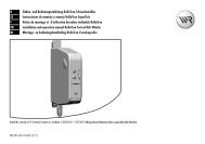
D Einbau- und Gebrauchsanleitung von RADEMACHER DuoFern-Rohrmotoren........................................1<br />
EN Installation and operating instructions for RADEMACHER DuoFern tubular motors ........................ 27<br />
Applicable for the following series: <strong>RolloTube</strong> I-<strong>line</strong> <strong>Sun</strong> Radio Medium (ILSFM ...)<br />
Please note:<br />
Site of installation:<br />
.................................................................................................................................<br />
Serial number:<br />
.................................................................................................................................<br />
VBD 560-4-D (06.11)
28<br />
i<br />
i<br />
i<br />
Dear Customer,<br />
With your purchase of this tubular motor, you have decided in favour of a quality product<br />
manufactured by RADEMACHER. We would like to thank you for your confidence.<br />
RADEMACHER tubular motors have been developed with the greatest possible<br />
convenience in mind. Having applied uncompromising quality standards, and carried out<br />
thorough testing, we are proud to be able to present you with this innovative product.<br />
It is brought to you by all the highly-qualified personnel<br />
here at RADEMACHER.<br />
These instructions...<br />
... serve to describe the installation, electrical connection and operation of RADEMACHER<br />
DuoFern tubular motors of series <strong>RolloTube</strong> I-<strong>line</strong> <strong>Sun</strong> Radio Medium (ILSFM...).<br />
Before you begin work, please read these instructions through completely and follow all<br />
the safety instructions.<br />
Please store these instructions in a safe place and pass them on to any future owners.<br />
Damage resulting from non-compliance with these instructions and safety instructions will<br />
void the guarantee. We assume no liability for any consequential damage.<br />
Key to symbols<br />
Danger of fatal electric shock.<br />
This sign warns of danger when working on electrical connections, components, etc.<br />
It requires that safety precautions be taken to protect the life and health of the person<br />
concerned.<br />
This concerns your safety.<br />
Please pay particular attention and carefully follow all instructions marked with this symbol.<br />
STOP<br />
EN<br />
CE Mark and Conformity<br />
The present product complies with the requirements of the current European and<br />
national directives.<br />
Conformity has been verified. The corresponding declarations and documentation are<br />
available on file at the manufacturer’s premises.<br />
This symbol warns of malpractices that can result in personal injury<br />
or property damage.<br />
NOTE/IMPORTANT/CAUTION<br />
In this way, we wish to make you aware of the following content in order to ensure<br />
optimal functionality.
i<br />
Contents<br />
Figures ...........................................................................................................3<br />
Dear Customer,... /These instructions... ............................................................28<br />
Key to symbols ..............................................................................................28<br />
Key to the overall view (Figure 1) ................................................................30<br />
General safety instructions...............................................................................31<br />
Proper use / operational conditions ..................................................................31<br />
Incorrect use .................................................................................................31<br />
Function of radio code ....................................................................................31<br />
Functional description .....................................................................................32<br />
Function of the fabric relief and blockage detection system ..................................32<br />
Function of the fabric tensioning and obstacle detection system ............................32<br />
Important assembly instructions .......................................................................33<br />
Preparing the awning system ...........................................................................33<br />
Mounting / dismounting the adapter (Fig. 2) * ..............................................33<br />
Mounting the catch with freewheel mechanism (Figures 3 and .a) * ................34<br />
Mounting the catch without freewheel mechanism (Fig. .b ) ...............................34<br />
Dismounting the catch (Fig. .c ) .....................................................................34<br />
Slide the tubular motor into the awning shaft (Fig. 4) ......................................35<br />
Preparation for use of precision tubes (Figures .a - .e ) .....................................35<br />
Mounting the roller shutter casing (Fig. 5 - 7) ..............................................37<br />
Preparing the awning for the electrical connection<br />
and commissioning (Figure 8) ......................................................................37<br />
Safety instructions for electrical connection ........................................................38<br />
The motor cable (Figure i) ..........................................................................38<br />
Electrical connection of the tubular motor (Fig. j) ............................................39<br />
Control with 1-pole switch (closer) (Figure k) .................................................39<br />
Connection and use of the cord circuit setting unit<br />
for end point setting (Figures l/m) ............................................................... 40<br />
End point adjustment......................................................................................41<br />
Manual adjustment of end points .....................................................................41<br />
Automatically setting the upper end point and manually setting the lower end point .42<br />
Manual setting of upper / lower endpoint with a cord circuit setting unit or<br />
with an external switch ...................................................................................43<br />
Manually setting of upper / lower endpoint with help of the<br />
set button on the tubular motor .......................................................................44<br />
Manually setting the upper / lower endpoints with DuoFern transmitters ..............44<br />
Test run / modifying the end points..................................................................44<br />
Configuring tubular motors ..............................................................................45<br />
Loading factory settings during the commissioning process ...................................45<br />
What to do if... ? ..........................................................................................46<br />
Technical specifications ...................................................................................47<br />
Connecting / disconnecting DuoFern transmitters ...............................................48<br />
Connecting / disconnecting a DuoFern transmitter with the help of a set button ......48<br />
Connect / disconnect the DuoFern central operating unit with the radio code ..........49<br />
EC declaration of conformity ............................................................................51<br />
Warranty conditions .......................................................................................51<br />
EN<br />
29
30<br />
Key to the overall view (Figure 1)<br />
(1) Side cover<br />
(2) Assembly screws<br />
(3) Bearing block<br />
(4) Drive bearing (click-bearing, item no. 4015K-09)<br />
(5) Retainer<br />
(6) Drive head<br />
(7) Set button<br />
(8) Adapter<br />
(9) Tubular motor<br />
(10) Catch<br />
(11) Awning shaft<br />
(12) Awning fabric<br />
(13) Motor cable<br />
(14) Limit ring<br />
(15) Retaining clip<br />
(16) Drive adapter<br />
(17) Base plate for drive bearing<br />
(18) Traverse member for awning<br />
(19) Joint arms of the awning<br />
After unpacking please check the following:<br />
EN<br />
◆ Check that the package contents matches the scope of delivery listed on the package.<br />
◆ Check that the motor type corresponds to the specifications on the type plate.
i<br />
i<br />
General safety instructions<br />
Danger due to electric shock when working on all electrical systems.<br />
◆ The electrical connection for the tubular motor and all work on the electrical systems<br />
may only be undertaken by an authorised qualified electrician and in accordance with<br />
the connection diagrams in these instructions (see pages 40/40/42).<br />
◆ Always undertake mounting and connection work with the equipment disconnected<br />
from the mains power.<br />
The use of defective equipment can lead to personal injury and damage<br />
to property (electric shocks, short circuiting).<br />
◆ Never use defective or damaged equipment.<br />
◆ Check the drive and mains cable beforehand for damage.<br />
◆ Consult our customer service department (see page ) in the event that you discover<br />
damage on the equipment.<br />
Proper use / operational conditions<br />
Only use the tubular motors for the electrical operation of awnings.<br />
IMPORTANT<br />
◆ The motor cable must be protected on the inside of the empty tube up to the junction<br />
box under observation of local electrical regulations.<br />
◆ Only use the manufacturer‘s original components and accessories.<br />
Only use tubular motors which correspond to the local conditions in<br />
terms of their output. Incorrectly dimensioned tubular motors can lead<br />
to damage.<br />
◆ Consult a specialist dealer when selecting the tubular motor and observe our tractive<br />
force specifications on our Website: www.rademacher.de<br />
Incorrect use<br />
Using the tubular motor for purposes other than those stated above is<br />
considered incorrect use.<br />
i Function of radio code<br />
You can control the radio tubular motor directly using the radio code in order, for example, to<br />
be also able to subsequently connect further DuoFern devices to the radio tubular motor<br />
after installation. Once the connection has been successfully established, you can carry<br />
out actions such as setting the limit stops for a radio tubular motor.<br />
The radio code can be found on the enclosed label:<br />
Example:<br />
Incorrect use leads to an increased risk of injury.<br />
◆ Train all personnel to safely use the tubular motor.<br />
Operating conditions<br />
EN<br />
◆ Do not allow children or persons with limited capabilities to use the fixed control units<br />
or remote control systems.<br />
◆ Watch the moving awning and keep other people away from the area until the<br />
movement has completed.<br />
For awning systems which can be operated out of sight of the operator:<br />
◆ Awnings may not be operated if work is being carried out nearby (e.g. windows<br />
being cleaned).<br />
For automatically actuated awnings:<br />
◆ Awnings must be disconnected from the power supply if work is being carried out<br />
nearby.<br />
Regular maintenance of awnings increases operational reliability.<br />
◆ Check the awnings regularly for poor balance or damaged <strong>line</strong>s and springs.<br />
◆ Have damaged awnings repaired by a specialist firm.<br />
◆ A continuous 230 V / 50 Hz mains supply must be available at the site of installation<br />
for the electrical connection in combination with on-site switchgear (fusing<br />
◆ The installation and operation of the DuoFern radio system and its components is<br />
only permitted for those systems and devices where a malfunction in the transmitter<br />
or receiver would not cause a danger to personnel or property or where this risk is<br />
already covered by other safety equipment.<br />
Never use the DuoFern radio system or its components for:<br />
systems with increased safety-relevant requirements or where there is an increased risk<br />
of accidents. Such use would require additional safety equipment. Observe the respective<br />
statutory regulations for the installation of such systems.<br />
NOTE<br />
Time window for activation via the radio code.<br />
After switching on the power supply, the radio code is active for a maximum 2 hours. Once this<br />
time has elapsed, activation using the radio code is no longer possible. Briefly disconnect<br />
the environmental sensor from the mains to reactivate the time window.<br />
31
32<br />
i<br />
i<br />
i<br />
Functional description<br />
The RADEMACHER DuoFern <strong>RolloTube</strong> I-<strong>line</strong> <strong>Sun</strong> Radio (RSFM...) series of tubular motors<br />
are designed for the electrical operation of awnings (extending / retracting).<br />
The internal DuoFern interface enables the motor to be integrated into a DuoFern radio<br />
network, making it possible to configure and control many automatic functions remotely<br />
with the help of a DuoFern transmitter (e.g. the DuoFern central operating unit).<br />
An additional switch can be connected to the tubular motor locally in order to enable<br />
manual operation.<br />
<strong>RolloTube</strong> I-<strong>line</strong> <strong>Sun</strong> Radio tubular motors are equipped with the new Safe-Drive system for<br />
position detection, torque monitoring and obstacle detection. The drive‘s compact design<br />
and the end point configuration ensures for straightforward and convenient installation.<br />
The <strong>RolloTube</strong> I-<strong>line</strong> <strong>Sun</strong> Radio impresses in daily operation with automatic fabric relief and<br />
tensioning (with reversing), ensuring optimal safety and gentle operation.<br />
Overview of functions:<br />
General tubular motor functions:<br />
◆ Commissioning with a single run command. Self-learning motor with automatic<br />
end point configuration for the upper end point.<br />
◆ Safe-Drive method for precise positioning, torque monitoring and obstacle detection.<br />
◆ Blockage and obstacle detection as well as an integrated fabric relief and tensioning<br />
system, including reversing function.<br />
◆ Obstacle detection can be arbitrarily configured thanks to the new snap-in FlexiClick<br />
system.<br />
◆ Quick and easy installation thanks to the new shorter design.<br />
◆ Optionally available: Universal RT ConfigTool for individual configuration of the<br />
motor parameters.<br />
Short description of the DuoFern radio system<br />
The DuoFern radio system enables bidirectional data exchange between the various<br />
participants of a DuoFern radio network. All of the switching commands from the DuoFern<br />
transmitter (e.g. DuoFern central operating unit) are received and acknowledged by the<br />
DuoFern components (actuators / sensors), insofar as both devices are interconnected.<br />
Function in the event of a fault or awning blockage:<br />
The tubular motor stops and automatically relieves the awning by shifting briefly in the<br />
opposite direction (reversing) in the event that the awning is blocked by an obstacle<br />
when retracting.<br />
NOTE<br />
Blocked awnings may not be moved until the fault or obstacle has been dealt with.<br />
Tubular motor functions in combination with DuoFern transmitters<br />
EN<br />
DuoFern environmental sensor Item no 9475<br />
DuoFern manual central operating unit Item no 9493<br />
RolloTron Pro Comfort DuoFern Item no 980x<br />
DuoFern manual transmitter standard Item no 9491-x<br />
DuoFern wall controller Item no 9494-xx<br />
Manual control (up/stop/down) ● ● ● ●<br />
Random function ● ●<br />
Manual operation (on/off) ● ●<br />
Timer (on/off) ● ●<br />
Automatic solar function (on/off) ● ●<br />
Solar program ● ●<br />
Automatic dawn function (on/off) ● ●<br />
Automatic dawn function ● ●<br />
Automatic dusk function (on/off) ● ●<br />
Automatic dusk function ● ● ●<br />
Automatic wind function (on/off)<br />
Wind function<br />
Direction of rotation for wind<br />
Automatic rain function (on/off)<br />
Rain function<br />
Direction of rotation for rain<br />
Ventilating position<br />
Reversal of rotational direction ● ● ●<br />
Connection test ● ●<br />
End point adjustment radio controlled ● ●<br />
Radio code<br />
Function of the fabric relief and blockage detection system<br />
Function of the fabric tensioning and obstacle detection system<br />
Function of the obstacle detection system when extending the awning:<br />
The tubular motor stops and automatically shifts briefly in the opposite direction in the<br />
event that the awning hits an obstacle while opening.<br />
Requirements for correct obstacle detection:<br />
◆ The catch (10) must be mounted with the freewheel mechanism activated (see<br />
Fig. .a; page 34).<br />
Automatic fabric relief during normal operation:<br />
During normal operation, the awning runs up to the upper end point and subsequently<br />
shifts briefly in the opposite direction (reversing), in order to automatically relieve the<br />
awning fabric.<br />
NOTE<br />
This function is only active if the upper end point is configured automatically, see page 44.<br />
Automatic fabric tensioning during normal operation:<br />
During normal operation, the awning runs up to the lower end point and subsequently<br />
shifts briefly in the opposite direction (reversing), in order to automatically tension the<br />
awning fabric.<br />
NOTE<br />
This function is only active if the upper end point is configured automatically, see page44.<br />
●<br />
●<br />
●<br />
●<br />
●<br />
●<br />
●<br />
●
STOP<br />
Important assembly instructions<br />
Incorrect assembly of the awning may lead to an increased risk of injury.<br />
For this reason, arrange to have all installation and repair work carried<br />
out by a specialist firm.<br />
Check:... :<br />
◆ ... that the awning is suitable for installation of the tubular motor.<br />
◆ ... that the tubular motor is a suitable size.<br />
◆ ... that the structural base is sufficiently stable for the operation of an electrically<br />
powered awning.<br />
IMPORTANT<br />
◆ Check that the voltage / frequency on the type plate corresponds to local mains<br />
conditions prior to installation.<br />
◆ All cables and equipment not required for operation of the equipment is to be removed<br />
or deactivated prior to installation of the tubular motor.<br />
◆ Moving drive parts to be operated at a height under 2.5 m from the floor must be<br />
protected.<br />
◆ If the tubular motor is to be controlled with a switch with a default OFF setting, then<br />
the switch is to be positioned in the <strong>line</strong> of sight of the tubular motor and at a height<br />
of at least 1.5 m.<br />
◆ The set button (7) for the tubular motor must be easily accessible and the motor<br />
cable (13) must be laid without kinking.<br />
For automatically actuated awnings:<br />
◆ A minimum gap of 0.4 m to other parts in the area must be maintained when the<br />
awning is fully extended.<br />
◆ Awnings used in an awning system must maintain a minimum height of 1.8 m.<br />
Preparing the awning system<br />
Risk of injury due to joint arms falling down (19). The joint arms (19)<br />
are under high spring tension and may fall down suddenly when the<br />
awning drive is released.<br />
◆ Retract the awning fully and secure the joint arms (19) with two ratchet straps prior<br />
to mounting the tubular motor in order to avoid sudden dropping.<br />
NOTE<br />
The preparation measures must be adapted to the existing awning system on site, due<br />
to the various models of awning available. The following describes the most important<br />
general steps for preparing the awning system for the installation of the <strong>RolloTube</strong> I-<strong>line</strong><br />
<strong>Sun</strong> Radio tubular motor.<br />
STOP<br />
Mounting / dismounting the adapter (Fig. 2) *<br />
* = The adapter is supplied pre-installed by the factory.<br />
1. Mounting the adapter (8)<br />
Slide the adapter (8) over the limit ring (14) on the drive head until<br />
it engages. In doing so, check the correct positioning of the groove in<br />
the adapter (8).<br />
1.<br />
2.<br />
3.<br />
EN<br />
There is a risk of short-circuits and fire in the event of direct weather<br />
influences to the unprotected tubular motor.<br />
The mounted tubular motor may never be subjected to direct rain or<br />
snow, as this may lead to life-threatening situations due to short-circuits<br />
and damage to the motor.<br />
◆ Only install the tubular motor in awning systems where the motor is structurally<br />
protected from the direct influences of rain and snow.<br />
◆ Install a suitable protective hood for the tubular motor, if necessary.<br />
Risk of injury when working at heights due to falling.<br />
◆ Take suitable measures to ensure safe working at heights.<br />
◆ Ensure that ladders and scaffolding stand securely.<br />
Fully retract the awning.<br />
Never drill or insert screws in the area<br />
of the drive. Doing so may damage the<br />
tubular motor.<br />
Secure the joint arms (19) with ratchet straps in order to avoid<br />
sudden dropping.<br />
Remove the awning gear mechanism.<br />
2. Dismantling the adapter (8)<br />
Press the two retaining springs on the limit ring (14) downwards and<br />
pull the adapter (8) off of the limit ring (14).<br />
33
34<br />
Mounting the catch with freewheel mechanism (Figures 3 and .a) *<br />
* = The catch is supplied pre-installed by the factory.<br />
3.a (10)<br />
(16)<br />
3.b<br />
3.c<br />
(10)<br />
(15)<br />
(10)<br />
(15)<br />
Mounting the catch without freewheel mechanism (Fig. .b )<br />
(16)<br />
Dismounting the catch (Fig. .c )<br />
(16)<br />
1.<br />
1.<br />
1.<br />
Press the side parts of the retaining clip (15) together and pull the<br />
catch (10) off of the drive adapter (16).<br />
EN<br />
IMPORTANT<br />
If the tubular motor is to be operated with obstacle detection, then the<br />
catch (10) must be mounted with free-wheeling action.<br />
Slide the adapter (10) onto the drive adapter (16) so that it can freewheel<br />
and so that it engages behind the retaining clip (15).<br />
Free-wheeling is given if the catch (10) can be easily turned back and<br />
forth.<br />
IMPORTANT<br />
It may be necessary to mount the catch (10) without the freewheel<br />
mechanism for very lightweight awnings or for awnings which do not<br />
run easily, in order to avoid premature switch-off.<br />
Slide the adapter (10) onto the drive adapter (16) so that it cannot<br />
free-wheel and so that it engages behind the retaining clip (15).<br />
NOTE<br />
◆ If the catch (10) is mounted without the freewheel mechanism, then<br />
the tubular motor will work without obstacle detection.
1.<br />
STOP<br />
Slide the tubular motor into the awning shaft (Fig. 4)<br />
4.a<br />
4.b<br />
1<br />
Never knock the motor (9) with force<br />
into the awning shaft (11).<br />
Doing so will cause serious damage.<br />
First slide the catch (10) into the awning shaft (11). 2. Subsequently press the tubular motor into the awning shaft (11) so that<br />
the adapter (8) is fully inserted into the awning shaft (11).<br />
Preparation for use of precision tubes (Figures .a - .e )<br />
IMPORTANT<br />
◆ Please only use precision tubes made from aluminium.<br />
4.c<br />
ALUMINIUM<br />
<strong>RolloTube</strong> I-<strong>line</strong> <strong>Sun</strong> Radio Medium (ILSFM...)<br />
<br />
EN<br />
IMPORTANT<br />
The set button (7) for the tubular motor must be easily accessible and the motor cable<br />
(13) must be laid without kinking.<br />
IMPORTANT<br />
In doing so, ensure that the adapter (8) does not slip off of the limit ring (14) on the<br />
drive head (6) during the assembly process. Otherwise malfunctions may occur, see page 49.<br />
1. Measure the distance between the adapter (8) and the rear third of the<br />
catch (10) and mark this distance on the precision tube.<br />
2. Saw a groove in the end of the precision tube 1 in order that the cam<br />
of the adapter (8) can be completely pressed into the tube.<br />
NOTE<br />
◆ There may not be any play between the groove 1 and the cam .<br />
3. Slide the tubular motor (9) into the precision tube.<br />
35
36<br />
Preparation for use of precision tubes (Figures .a - .e )<br />
4.d<br />
4.e<br />
STOP<br />
5.<br />
EN<br />
4. Mark the four fastening holes and subsequently drill them through the<br />
precision tube in the catch (10).<br />
ATTENTION<br />
◆ Never drill deeper than 10 mm into the catch (10).<br />
◆ Never drill in the area of the drive. Doing so will cause serious<br />
damage.<br />
Screw or rivet the precision tube to the catch (10).<br />
Use four self-tapping sheet metal screws, plastic screws or pop rivets.
1.<br />
Mounting the roller shutter casing (Fig. 5 - 7)<br />
Screw the drive bearing (4) to the previously removed bearing block<br />
(3) (see Fig. 5).<br />
IMPORTANT<br />
Mount the drive bearing (4) so that the bearing block (3) enables easy access to the<br />
set button (7) on the tubular motor (9) at all times.<br />
If excessively long assembly screws are used , the drive bearing (4)<br />
may be bent or damaged (see Fig. 6) and below.<br />
The assembly screws (2) must sit flush with the base plate (17) as otherwise the drive<br />
bearing (4) may be bent and be pressed up in front of the base plate (17).<br />
This applies particularly if the inner assembly holes are used on the base plate (17).<br />
(17) (2)<br />
Preparing the awning for the electrical connection<br />
and commissioning (Figure 8)<br />
1. Place the side cover (1) (if available) back onto the bearing block (3),<br />
(see Fig. 8).<br />
2. Release the ratchet straps from the joint arms.<br />
3.<br />
Drive bearing (as click bearing)<br />
Finally, check that the installation work has been carried out properly.<br />
2.<br />
3.<br />
4.<br />
Drive bearing (all other bearing types)<br />
EN<br />
Subsequently slide the bearing block (3) back onto the cross member<br />
(18) of the awning until the drive bearing (4) fully engages on the<br />
drive head (6) (see Fig. 7).<br />
Check that the set button (7) on the motor (9) is easily accessible. Correct<br />
the position of the drive bearing (4) on the bearing block (3) if necessary.<br />
NOTE<br />
The tubular motor can be fitted into the click bearing (4) in 4 positions. The motor can<br />
be released from the click bearing (4) at any time by means of expanding the retaining<br />
clips (5).<br />
Finally screw the bearing block (3) back onto the cross member (18)<br />
of the awning.<br />
The assembly of other bearing types is undertaken in the same way as in the previous<br />
description. In doing so, pay attention to the special characteristics of the respective bearing<br />
type, e.g. the connection between the drive head and the drive bearing with a cotter pin.<br />
37
38<br />
Safety instructions for electrical connection<br />
Danger due to electric shock when working on all electrical systems.<br />
◆ The electrical connection for the tubular motor and all work on the electrical systems<br />
may only be undertaken by an authorised qualified electrician and in accordance with<br />
the connection diagrams in these instructions.<br />
◆ Disconnect all poles from the mains and secure them against unintentional reconnection.<br />
◆ Check that the system is dead.<br />
◆ Always undertake mounting and connection work with the equipment disconnected<br />
from the mains power<br />
Risk of short-circuit resulting from damaged cable.<br />
◆ Lay all motor cables (13) so that they cannot be damaged by moving parts of the<br />
awning.<br />
◆ Lay the motor cable (13) in the empty tube up to the wall duct.<br />
◆ Seal the wall duct after laying the motor cable (13) in order to prevent water<br />
penetration.<br />
◆ The mains connection for the drive may only be connected with the same conduction<br />
type. Consult customer services if necessary.<br />
The motor cable (Figure i)<br />
9<br />
(7)<br />
(13)<br />
external switch<br />
L<br />
N<br />
PE<br />
Fixed-installation devices...<br />
STOP<br />
EN<br />
...must be equipped on the installation side with a circuit-breaker for each phase in<br />
accordance with DIN VDE 0700. Switches with a contact opening width of min. 3 mm<br />
can be used as circuit-breakers (e.g. power switch, power circuit breaker or residualcurrent-operated<br />
circuit-breaker).<br />
Risk of short-circuit resulting from water in the event of improper<br />
cabling.<br />
Never lay the motor cable (13) vertically upwards, as otherwise water may collect on the<br />
cable and run into the motor, leading to damage. Lay the cable in a loop. The loop will<br />
cause any water on the cable to collect at the lowest point, from where it can drain off.<br />
1. Feed the motor cable (13) into the designated junction box or terminal<br />
box after mounting the motor in place.<br />
Colour scale for the motor leads (13)<br />
◆ = external switch (white)<br />
L = phase (black)<br />
N = neutral (blue)<br />
PE = earth (green / yellow)<br />
= Antenna (violet)<br />
The antenna is integrated flush with the cable.<br />
(7) = Set button on tubular motor
Electrical connection of the tubular motor (Fig. j)<br />
10<br />
(a)<br />
(b)<br />
(c)<br />
11 (a)<br />
(b)<br />
(c)<br />
(d)<br />
(d)<br />
(e) (f) (g) (h) (i)<br />
Control with 1-pole switch (closer) (Figure k)<br />
The radio tubular motor can be controlled locally by means of connecting a 1-pole switch<br />
(closer) to the “external switch” conductor.<br />
In doing so, the switching sequence is as follows:<br />
Retract/stop/extend/stop, and so on.<br />
(e) (f) (g) (h) (i)<br />
Legend<br />
(a) = set button (7)<br />
(b/d) = socket box<br />
(c) = Mains 230 V/50 Hz<br />
Pin assignment<br />
(e) = PE green/yellow<br />
(f) = N blue<br />
(g) = L black<br />
(h) = external switch white (not used in this example)<br />
(i) = Antenna violet<br />
EN<br />
IMPORTANT<br />
◆ If the “external switch” (h) lead is not used, then it must be connected to the<br />
neutral conductor (f), (see fig. j).<br />
Legend<br />
(a). = set button (7)<br />
(b) = 1-pole switch<br />
(c) = Mains 230 V/50 Hz<br />
(d). = Socket box<br />
Pin assignment<br />
(e). = PE green/yellow<br />
(f). = N blue<br />
(g). = L black<br />
(h). = external switch white *<br />
(i). = Antenna violet<br />
* maximum cable length between tubular motor and external switch = 10 m<br />
IMPORTANT<br />
◆ If the “external switch” (h) lead is not used, then it must be connected to the<br />
neutral conductor (f) (see fig. j).<br />
39
40<br />
Connection and use of the cord circuit setting unit<br />
for end point setting (Figures l/m)<br />
12<br />
13<br />
(20)<br />
Plunger<br />
ON<br />
ON<br />
SET<br />
EN<br />
For initial installation, the roller shutter engineer can connect the motor cable (13) to a<br />
commercially available cord switch device (20) (type no. 4090) in order to configure<br />
the end points for the tubular motors.<br />
After mounting, feed cables (e - h) for the motor cable (13) to the designated switching<br />
point (e.g. up to the switch socket).<br />
Use the “external switch” conductor (h).<br />
If the conductor “external switch” (h) of motor cable (13) is connected to the “SET<br />
button” of the cord circuit setting device (20), then you can use this set button to<br />
configure the end points.<br />
NOTE<br />
Observe the various configuration options for the end points detailed in the “End point<br />
adjustment” chapter (see below) and on the following pages.<br />
Open the terminal contacts by pressing the plungers and connect all of<br />
the wires of the motor cable (13) as follows:<br />
Motor cable > cord circuit setting device<br />
Function > Function<br />
L > L1 (direction of rotation 1)<br />
External switch > set <strong>line</strong><br />
N > N<br />
PE > PE<br />
After connection is completed, the buttons of the cord circuit setting<br />
unit (20) will have the following functions:<br />
Rocker switch in central position = motor voltage off<br />
Rocker switch up (s)-position = motor voltage on<br />
SET-button = set button = retract awning/stop/extend/stop/etc.<br />
IMPORTANT<br />
The external switch lead (h) must be connected to neutral conductor (f)<br />
after configuration of the end points (see fig. j).
End point adjustment<br />
Mortal danger due to tearing off the motor cable (13).<br />
Ensure that the motor cable (13) is not taken up by the awning shaft (11) or torn off<br />
during the configuration process.<br />
You have various options for configuring the end points, which are<br />
described in the following section:<br />
◆ Setting the upper end point automatically (by means of blockage detection) and<br />
manually setting the lower end point.<br />
◆ Manually setting the upper end point and lower end point.<br />
Important relationship between the obstacle detection system and<br />
installation of the catch.<br />
◆ If the catch is mounted without the freewheel mechanism, then the tubular motor<br />
will not switch off automatically, as it will not detect obstacles.<br />
◆ If the catch is mounted with the freewheel mechanism, then the tubular motor will<br />
switch off automatically when extending the awning as soon as the freewheel travel<br />
is overcome.<br />
Manual adjustment of end points<br />
Initial installation<br />
For initial installation, the engineer can carry out the end point configuration with the help<br />
of the set button (7) on the motor (9) or with a commercially available cord switch<br />
device (20). Please observe the safety instructions in the cord circuit setting unit manual.<br />
Subsequent modification of the end points with external controllers<br />
If you want to subsequently modify the end points for your tubular motor, you can use<br />
an external switch as set button, as previously shown, or you can use your tubular motor<br />
controller in order to readjust the endpoints.<br />
STOP<br />
EN<br />
IMPORTANT<br />
◆ End points must be set in order to switch off the motor when they are reached for<br />
both directions of travel up (s)/ down (t).<br />
◆ The tubular motor must be fully installed.<br />
◆ The set button (7) must be easily accessible.<br />
◆ Disconnect the cord circuit setting unit (20) after undertaking the<br />
end point configuration and connect the tubular motor in accordance<br />
with connection diagrams (j).<br />
◆ The external switch lead (h) must be connected to neutral conductor (f)<br />
after configuration of the end points (see fig. j).<br />
Risk of injury when adjusting the awning due to crushing of the hands<br />
by the moving awning.<br />
Never reach into the area of the awning shaft and joint arms when the motor is running.<br />
41
1.<br />
2.<br />
3.<br />
4.<br />
5.<br />
6.<br />
7.<br />
42<br />
Automatically setting the upper end point and manually setting the lower end point<br />
ON<br />
or<br />
SET or<br />
ON<br />
or OFF<br />
Symbols and actions when connecting a cord circuit setting unit (20)<br />
or<br />
when connecting an external switch.<br />
Switch on the mains power.<br />
Subsequently the drive shifts the awning in the opposite direction.<br />
Press and hold the set button (7) on the motor until the lower end point is reached.<br />
Release the set button (7) as soon as the awning has reached the desired position.<br />
The motor stops and the lower end point is stored.<br />
EN<br />
The awning will first retract to the upper stop until the tubular motor switches off automatically.<br />
If the tubular motor is already logged on to the DuoFern network, then the direction of travel can also be specified with DuoFern transmitters.<br />
IMPORTANT<br />
◆ Never interrupt the sequence while the process is running. The awning must retract without interruption.<br />
◆ The awning must retract first. If the awning first extends, then the direction of travel must first be reversed by pressing the SET button<br />
several times or by using the external switch.<br />
◆ The switching sequence for the SET button or the external switch is: Retract/stop/extend/stop, and so on.<br />
You can correct the lower end point in small steps by briefly pressing the set button (7).<br />
IMPORTANT<br />
◆ In the event that a malfunction occurs during configuration, e. g. in the event that the tubular motor only runs for a single rotation even<br />
when the set button is pressed, it is unlikely that the tubular motor is faulty. Possibly the adapter (8) has slipped off of the drive head (6).<br />
◆ Check and, if necessary, correct the positioning of the adapter (8), (see page 49).<br />
NOTE<br />
In the event that the end point configuration fails, you must reset the tubular motor to the factory setting (see page 48), in order to repeat the process.<br />
Finally, disconnect the tubular motor from the mains for a few seconds. Subsequently, the tubular motor is ready<br />
for operation.<br />
NOTE<br />
The fabric relief and tensioning systems are only active if the end points have been configured as described above.<br />
IMPORTANT<br />
◆ The external switch lead (h) must be connected to neutral conductor (f) after configuration of the end points.
1.<br />
2.<br />
3.<br />
4.<br />
5.<br />
6.<br />
7.<br />
Manual setting of upper / lower endpoint with a cord circuit setting unit or<br />
with an external switch<br />
SET<br />
SET +<br />
SET<br />
SET<br />
ON<br />
or<br />
or<br />
or +<br />
or<br />
or<br />
or<br />
OFF<br />
OFF<br />
ON<br />
Symbols and actions when connecting a cord circuit setting unit (20)<br />
or<br />
when connecting an external switch.<br />
Switch off the mains power.<br />
If a cord circuit setting unit (20) is being used, then the rocker switch must be positioned to the centre position.<br />
Press and hold the SET button or the external switch.<br />
Additionally switch on the mains power.<br />
After approx. 6 seconds the tubular motor starts and the awning moves up or down.<br />
Release the SET button as soon as the awning have reached the desired position.<br />
The motor stops and the first end point is stored.<br />
You can correct the end point in small steps by briefly pressing the SET button.<br />
EN<br />
IMPORTANT<br />
In the event that a malfunction occurs during configuration, e.g. in the event that the tubular motor only runs for a single rotation even when<br />
the SET button is pressed, it is unlikely that the tubular motor is faulty. Possibly the adapter (8) has slipped off of the motor head.<br />
Check and, if necessary, correct the positioning of the adapter (8), (see page 49).<br />
NOTE<br />
The end points are maintained permanently even in the event of power failure.<br />
Switch off the mains power again.<br />
Repeat points 2. to 5. for the second end point.<br />
IMPORTANT<br />
◆ The external switch lead (h) must be connected to neutral conductor (f) after configuration of the end points.<br />
◆ If the end points have been set manually, the “fabric tensioning” function will be deactivated.<br />
43
1.<br />
2.<br />
3.<br />
4.<br />
5.<br />
6.<br />
44<br />
Manually setting of upper / lower endpoint with help of the<br />
set button on the tubular motor<br />
ON<br />
or<br />
SET or<br />
ON<br />
Symbols and actions when connecting a cord circuit setting unit (20)<br />
or<br />
when connecting an external switch.<br />
Switch off the mains power.<br />
Press and hold the set button (7) on the tubular motor until the desired end point is reached.<br />
The awning retracts / extends.<br />
Test run / modifying the end points<br />
Check the configuration and allow the roller shutters to run in both<br />
directions, until the end points switch off the motor.<br />
Thermal protection<br />
The tubular motors are designed for brief operation (approx. 4 mins).<br />
If this period is exceeded, or if the equipment is switched over frequently, then the motor<br />
may heat up and the thermal protection system will shut it off.<br />
In this case, allow the motor to cool down for 20 minutes.<br />
You can correct the end point in small steps by briefly pressing the set button (7).<br />
IMPORTANT<br />
In the event that a malfunction occurs during configuration, e. g. in the event that the tubular motor only runs for a single rotation even when<br />
the set button is pressed, it is unlikely that the tubular motor is faulty. Possibly the adapter (8) has slipped off of the drive head (6).<br />
Check and, if necessary, correct the positioning of the adapter (8), (see page 49).<br />
NOTE<br />
The end points are maintained permanently even in the event of power failure.<br />
EN<br />
Move the awning in the desired direction of travel. In doing so, observe the switching sequence.<br />
◆ The switching sequence for the SET button or the external switch is: Retract/stop/extend/stop, and so on.<br />
◆ If the tubular motor is already logged on to the DuoFern network, then the direction of travel can also be specified with DuoFern transmitters.<br />
Release the set button (7) as soon as the awning has reached the desired position.<br />
The motor stops and the first end point is stored.<br />
Repeat points 2. to 4. for the second end point.<br />
IMPORTANT<br />
◆ The external switch lead (h) must be connected to neutral conductor (f) after configuration of the end points.<br />
◆ If the end points have been set manually, the “fabric tensioning” function will be deactivated.<br />
Manually setting the upper / lower endpoints with DuoFern transmitters<br />
NOTE<br />
The end points can also be set with DuoFern manual transmitters such as the 9491-x or<br />
DuoFern central operating unit 9493.<br />
In order to do so, please read the operating instructions for the corresponding DuoFern<br />
transmitter.<br />
Persons can be injured or property damaged if end points are configured<br />
using DuoFern transmitters without a direct <strong>line</strong> of sight to the awning.<br />
◆ Watch the moving awning and keep other people away from the area until<br />
the movement has completed.<br />
Modifying the end points<br />
Move the awning back to the centre position and begin the process again.
1.<br />
2.<br />
Configuring tubular motors<br />
The tubular motors can be individually configured with the help of a cord circuit setting<br />
unit (20).<br />
The following configurations are possible.<br />
◆ Reload the factory settings.<br />
Loading factory settings during the commissioning process<br />
Automatic configuration of the upper end point is available again once the factory settings<br />
have been loaded.<br />
NOTE<br />
We recommend undertaking these settings with two persons.<br />
IMPORTANT<br />
The tubular motor may not be in operation.<br />
3. 10 s<br />
4.<br />
5.<br />
A. + B.<br />
SET<br />
ON<br />
SET<br />
or<br />
or<br />
or<br />
or<br />
or<br />
OFF<br />
ON<br />
OFF<br />
EN<br />
NOTE<br />
Additional settings can be undertaken with the optionally available RT ConfigTool. Please<br />
refer to the information on our Website www.rademacher.de.<br />
Factory settings:<br />
End points: No end points stored<br />
Fabric tensioning (reversing) after the<br />
end point has been reached or switching<br />
on / off after obstacle detection: activated<br />
Symbols and actions when connecting a cord circuit setting unit (20)<br />
or<br />
when connecting an external switch.<br />
Switch off the mains power.<br />
If a cord circuit setting unit (20) is being used, then the rocker switch must be positioned to the centre position.<br />
First press and hold the set button (7) on the tubular motor (9) and subsequently press and hold the SET button<br />
on the cord circuit setting device (20) (possibly a second person carries this out).<br />
Additionally switch on the mains power. Hold all buttons.<br />
After approx. 10 seconds the tubular motor acknowledges loading of the factory settings by briefly running up<br />
and down.<br />
Release the set button (7) on the tubular motor (9) and the SET button (or the external switch, if connected).<br />
Switch off the mains power again.<br />
45
46<br />
i<br />
What to do if... ?<br />
...the motor fails to start?<br />
Possible cause:<br />
◆ Mains power not available.<br />
◆ The thermal protection system has triggered.<br />
Solution:<br />
◆ Check the power with a meter to ensure that the supply voltage (230 V / 50 Hz)<br />
is available and check the wiring.<br />
◆ Wait approx. 20 minutes until the motor has cooled down.<br />
...The tubular motor stops after a short period of time during the<br />
configuration and test procedures?<br />
Possible cause:<br />
◆ The adapter (8) may have slipped off of the limit ring (14) on the drive head (6).<br />
Solution:<br />
◆ Check that the adapter (8) sits flush with the drive head (6) and is fully inserted<br />
into the awning shaft (11).<br />
Slide the adapter (8) back so that it is flush with the drive head (6) and slide the<br />
tubular motor into the awning shaft (11) until the adapter (8) is flush with the awning<br />
shaft (11), see Fig. 2 and 4. Re-adjust the end points if necessary, see<br />
page 43.<br />
EN<br />
...The tubular motor stops between the two end points during normal<br />
operation?<br />
Possible cause:<br />
◆ The thermal protection system has triggered.<br />
Solution:<br />
◆ Wait approx. 20 minutes until the motor has cooled down.<br />
The tubular motor stops whilst extending the awning?<br />
Possible cause:<br />
◆ The motor must push the awning fabric out, because the shaft is not running smoothly<br />
or it is corroded.<br />
Solution:<br />
◆ Mount the catch (10) without the freewheel mechanism (see page ).
i<br />
Technical specifications<br />
Motor series<br />
Type: 15/16<br />
15<br />
16<br />
230<br />
50<br />
145<br />
0.64<br />
4<br />
4<br />
0.75<br />
3<br />
32<br />
H<br />
I<br />
IP 44<br />
*<br />
487<br />
45<br />
2<br />
25/16<br />
25<br />
16<br />
230<br />
50<br />
191<br />
0.83<br />
4<br />
4<br />
0.75<br />
3<br />
32<br />
H<br />
I<br />
IP 44<br />
*<br />
546<br />
45<br />
2<br />
ILSFM ...<br />
35/16<br />
35<br />
16<br />
230<br />
50<br />
198<br />
0.86<br />
4<br />
4<br />
0.75<br />
3<br />
32<br />
H<br />
I<br />
IP 44<br />
*<br />
546<br />
45<br />
2<br />
45/12<br />
45<br />
12<br />
230<br />
50<br />
205<br />
0.89<br />
4<br />
4<br />
0.75<br />
3<br />
32<br />
H<br />
I<br />
IP 44<br />
*<br />
546<br />
45<br />
2<br />
[Nm]<br />
[RPM]<br />
[V]<br />
[Hz]<br />
[W]<br />
[A]<br />
[Min.]<br />
[mm 2 ]<br />
[m]<br />
[R]<br />
[mm]<br />
[mm]<br />
Nominal torque:<br />
Idling speed:<br />
Nominal voltage:<br />
Frequency:<br />
Nominal power:<br />
Power consumption:<br />
Cyclic duration factor (KB):<br />
Number of wires:<br />
Core cross section:<br />
Cable length (standard):<br />
End switching range: (number of revolutions)<br />
Insulation class:<br />
Protection class:<br />
Protection class in accordance with VDE 700:<br />
Conduction class: (* = rubber)<br />
Motor length without bearing:<br />
Tube diameter:<br />
Number of parallel tubular motors connectible (when using<br />
RADEMACHER controllers, e. g. Troll Comfort)<br />
EN<br />
47
1.<br />
2.<br />
3.<br />
4.<br />
5.<br />
6.<br />
48<br />
Connecting / disconnecting DuoFern transmitters<br />
Every DuoFern transmitter that is required for operation has to be assigned to the tubular<br />
motor in order that the radio tubular motor can be controlled with a DuoFern transmitter.<br />
You can assign a maximum of 20 DuoFern transmitters, e.g. DuoFern manual central<br />
operating unit (type no. 9493); DuoFern standard manual transmitter (type no. 9491)<br />
etc. to the radio tubular motor.<br />
ON<br />
or<br />
ON<br />
10 s<br />
EN<br />
There are various ways to connect the DuoFern transmitter to the<br />
radio tubular motor or to disconnect the radio tubular motor:<br />
1. Connect / disconnect a DuoFern transmitter with the help of a set button on the<br />
tubular motor.<br />
2. Connect / disconnect a DuoFern transmitter with the help of the radio code.<br />
3. Remotely log on / log off a DuoFern transmitter with the help of the DuoFern central<br />
operating unit (please refer to the DuoFern central operating unit’s operating<br />
manual).<br />
Connecting / disconnecting a DuoFern transmitter with the help of a set button<br />
Points 1 to 4.<br />
Set button (7) with LED<br />
Symbols and actions when connecting a cord circuit setting unit (20)<br />
or<br />
when connecting an external switch.<br />
Switch on the mains power.<br />
Activate connect / disconnect mode on the radio tubular motor.<br />
Press and hold the set button (7) for at least 10 seconds.<br />
The set button (7) lights up orange by way of acknowledgement.<br />
Subsequently activate connect / disconnect mode on the desired DuoFern transmitter. In order to do so, please<br />
refer to the operating manual for the corresponding DuoFern transmitter or refer to the “Login matrix DuoFern”<br />
information on our website (www.rademacher.de).<br />
In addition, please observe the remaining time window in which you are able to connect or disconnect the DuoFern<br />
transmitter to/from the radio tubular motor.<br />
The radio tubular motor acknowledges successful connection / disconnection by starting up briefly and the set<br />
button LED turns green.<br />
NOTE<br />
The status LED lights up red if the connect / disconnect process fails, for example if :<br />
◆ 20 DuoFern transmitters have already been registered.<br />
◆ an unsuitable device (e.g. other DuoFern actuator) is registered.<br />
◆ an attempt is made to log-off a DuoFern transmitter that is not logged-on.<br />
If necessary, you can subsequently connect / disconnect the next DuoFern transmitter. In order to do so, repeat<br />
points 1 to 4.
1.<br />
2.<br />
3.a<br />
3.b<br />
4.<br />
5.<br />
6.<br />
7.<br />
8.<br />
Connect / disconnect the DuoFern central operating unit with the radio code<br />
Button<br />
M<br />
OK<br />
OK<br />
M<br />
OK<br />
OK<br />
OK<br />
OK<br />
Display<br />
EN<br />
Each DuoFern transmitter that is required for operation has to be assigned to the tubular motor in order that the radio tubular motor can be<br />
controlled with a DuoFern transmitter.<br />
Select the “Radio Code” menu on the DuoFern central operating unit:<br />
M Main menu<br />
System settings<br />
2 Radio settings<br />
2 . 2 Radio code<br />
Confirm selection.<br />
Enter the six-character radio code of the DuoFern tubular motor and confirm each figure (see enclosed sticker).<br />
If necessary you can jump back to the previous figure to correct it.<br />
Upon confirmation of the last figure you can activate ...<br />
... connect mode<br />
or<br />
disconnect mode on the radio tubular motor.<br />
Exit the menu.<br />
Select menu “2.,1 Connect/disconnect” on the central operating unit.<br />
Activate function “2.,1 Connect/disconnect” on the central operating unit.<br />
The number of logged on actuators is indicated on the display (e. g. 0 in the event of initial installation).<br />
49
9.<br />
10.<br />
11.<br />
12.<br />
13.<br />
14.<br />
50<br />
Connect / disconnect the DuoFern central operating unit with the radio code<br />
Button<br />
OK<br />
OK<br />
M<br />
Display<br />
Activate the central operating unit’s “connect” or “disconnect” mode.<br />
= connect mode<br />
= disconnect mode<br />
NOTE<br />
If disconnected, the radio tubular motor will be deleted from all of the groups in which it was previously positioned.<br />
After the connection, select the following for the new actuator:<br />
a) a group number<br />
b) a member number<br />
Confirm the member and group numbers.<br />
Then enter a name for the radio tubular motor.<br />
Confirm the name.<br />
The number of logged on devices is again indicated on the display. The radio tubular motor and the DuoFern central operating unit are now<br />
either connected or disconnected.<br />
Back to the DuoFern central operating unit’s normal view<br />
Press the key repeatedly.<br />
NOTE<br />
The radio tubular motor can now be configured via the DuoFern central operating unit.<br />
EN
i EC declaration of conformity<br />
Tubular motors of series <strong>RolloTube</strong> I-<strong>line</strong> <strong>Sun</strong> Radio Medium (Art. no. ILSFM..)<br />
fulfil the requirements of the following guide<strong>line</strong>s and standards:<br />
2006/95/EC<br />
Low-voltage directive<br />
- EN 60335-1:2007-02<br />
- EN 60335-2-97:2009-10<br />
1999/5/EG<br />
R&TTE directive<br />
- EN 300 220-1: V2.3.1 (2010-02)<br />
- EN 300 220-2: V2.3.1 (2010-02)<br />
- EN 301 489-1: V1.6.1 (2004-12)<br />
- EN 301 489-3: V1.4.1 (2002-08)<br />
- EN 50371:2002<br />
The conformity has been verified and the corresponding declarations and documentation<br />
are available on file at the manufacturer’s premises.<br />
i Warranty conditions<br />
RADEMACHER Geräte-Elektronik GmbH provides a 5 year guarantee for new equipment<br />
installed in accordance with the installation instructions. All construction faults, material<br />
defects and manufacturing defects are covered by the warranty.<br />
The following are not covered by the warranty:<br />
◆ Improper mounting or installation<br />
◆ Failure to observe the mounting and operating instructions<br />
◆ Improper operation or loading<br />
◆ External influences such as impacts, knocks or weather influences<br />
◆ Repairs and modifications carried out by third-party, unauthorised persons<br />
◆ The use of improper accessories<br />
◆ Damage caused by impermissible power surges (e.g. lightening).<br />
◆ Malfunctions caused by frequency overlapping and other radio disturbances.<br />
EN<br />
RADEMACHER shall remedy any defects, which occur within the warranty period free of<br />
charge either by repair or by replacement of the affected parts or by supply of a new<br />
replacement unit or one to the same value. There is no general extension of the original<br />
warranty period by delivery of a replacement or by repair as per the terms of the warranty.<br />
51
RADEMACHER<br />
Geräte-Elektronik GmbH & Co. KG<br />
Buschkamp 7<br />
46414 Rhede (Germany)<br />
info@rademacher.de<br />
www.rademacher.de<br />
Service:<br />
Hot<strong>line</strong> 01805 933-171*<br />
Fax +49 2872 933-253<br />
service@rademacher.de<br />
* 14 cents / minute from a German fixed <strong>line</strong> network operated by DT AG/<br />
Mobile charges max. 42 cents / minute (applies to Germany only)<br />
Subject to technical modifications, misprints and errors excepted. Illustrations not binding.