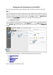
Bedienungsanleitung RolloTube I-line Sun Funk - Rademacher
Bedienungsanleitung RolloTube I-line Sun Funk - Rademacher
Bedienungsanleitung RolloTube I-line Sun Funk - Rademacher

Sie wollen auch ein ePaper? Erhöhen Sie die Reichweite Ihrer Titel.
YUMPU macht aus Druck-PDFs automatisch weboptimierte ePaper, die Google liebt.
40<br />
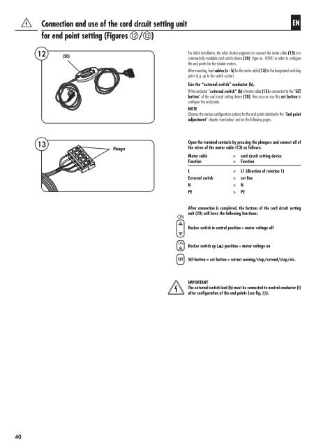
Connection and use of the cord circuit setting unit<br />
for end point setting (Figures l/m)<br />
12<br />
13<br />
(20)<br />
Plunger<br />
ON<br />
ON<br />
SET<br />
EN<br />
For initial installation, the roller shutter engineer can connect the motor cable (13) to a<br />
commercially available cord switch device (20) (type no. 4090) in order to configure<br />
the end points for the tubular motors.<br />
After mounting, feed cables (e - h) for the motor cable (13) to the designated switching<br />
point (e.g. up to the switch socket).<br />
Use the “external switch” conductor (h).<br />
If the conductor “external switch” (h) of motor cable (13) is connected to the “SET<br />
button” of the cord circuit setting device (20), then you can use this set button to<br />
configure the end points.<br />
NOTE<br />
Observe the various configuration options for the end points detailed in the “End point<br />
adjustment” chapter (see below) and on the following pages.<br />
Open the terminal contacts by pressing the plungers and connect all of<br />
the wires of the motor cable (13) as follows:<br />
Motor cable > cord circuit setting device<br />
Function > Function<br />
L > L1 (direction of rotation 1)<br />
External switch > set <strong>line</strong><br />
N > N<br />
PE > PE<br />
After connection is completed, the buttons of the cord circuit setting<br />
unit (20) will have the following functions:<br />
Rocker switch in central position = motor voltage off<br />
Rocker switch up (s)-position = motor voltage on<br />
SET-button = set button = retract awning/stop/extend/stop/etc.<br />
IMPORTANT<br />
The external switch lead (h) must be connected to neutral conductor (f)<br />
after configuration of the end points (see fig. j).