Blue Reef 1000 _502 D + GB - Aquawebkatalog
Blue Reef 1000 _502 D + GB - Aquawebkatalog
Blue Reef 1000 _502 D + GB - Aquawebkatalog

Erfolgreiche ePaper selbst erstellen
Machen Sie aus Ihren PDF Publikationen ein blätterbares Flipbook mit unserer einzigartigen Google optimierten e-Paper Software.
<strong>Blue</strong> <strong>Reef</strong> <strong>1000</strong><br />
Unterschrankfiltersystem<br />
Bedienungsanleitung D<br />
Mit dem Kauf dieses Filters haben Sie sich für ein Qualitätsprodukt entschieden. Er ist speziell für<br />
den aquaristischen Gebrauch entwickelt worden und von Fachleuten erprobt. Mit diesem Gerät sind<br />
Sie bei richtiger Anwendung in der Lage, die organischen Verunreinigungen Ihres<br />
Meerwasseraquariums einfach und wirksam zu entfernen.<br />
GmbH<br />
Gewerbepark 24, D- 49143 Bissendorf, Germany<br />
______________________________________________________________________________<br />
1
1. Lieferumfang<br />
Das Filtersystem <strong>Blue</strong> <strong>Reef</strong> <strong>1000</strong> besteht aus:<br />
- dem Filterbehälter aus Acrylglas mit Deckel und Schiebetüren<br />
- dem patentierten Vorfiltermodul mit Schubladen<br />
- dem Rieselfilter mit Verrieselungsplatte, gefüllt mit AB Aqua Medic Bactoballs<br />
- dem Abschäumer Turboflotor <strong>Blue</strong> 3000 mit Schaumtopf und Deckel<br />
- der Dispergatorpume incl. AB Aqua Medic Nadelrad<br />
- der Förderpumpe Ocean Runner 3500<br />
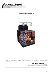
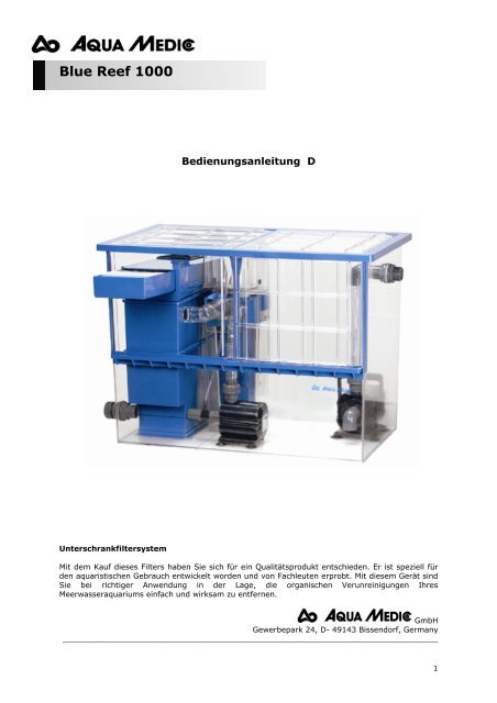
Abb. 1: <strong>Blue</strong> <strong>Reef</strong> <strong>1000</strong><br />
2. Allgemeine Beschreibung des Systems<br />
1. Zulaufdurchführung<br />
(auf der Rückseite)<br />
2. Vorfilter<br />
(Schublade)<br />
3. Rieselfilter mit<br />
Bactoballs<br />
4. Verschraubung für<br />
Umwälzpumpe oder<br />
Erweiterung<br />
5. Dispergatorpumpe<br />
OR 2500<br />
6. Turboflotor <strong>Blue</strong><br />
3000<br />
7. Förderpumpe OR<br />
3500<br />
8. Durchführung für<br />
Druckleitung<br />
Das Wasser fließt aus dem Aquarium über den Überlaufschacht - oder eine andere<br />
Überlaufeinrichtung (z. B. ein AB Aqua Medic Überlaufkasten) auf den Vorfilter mit der Schublade.<br />
Hier wird es mechanisch gereinigt. Die Schublade ist mit blauem Filterschwamm gefüllt, der durch<br />
ein Filtervlies abgedeckt wird. Unterhalb des Filterschwammes befinden sich zwei Filterbehälter mit<br />
Bactoballs als Biofilter.<br />
Aus dem unteren Filterbehälter saugt der Turboflotor <strong>Blue</strong> 3000 Wasser an. Die Vorfilterkammer<br />
besitzt in einer Höhe von 15 cm einen Überlauf in den Filtersumpf. Diese Einrichtung bewirkt, dass<br />
der Turboflotor an der Saugseite der Pumpe immer einen konstanten Wasserstand hat. Dieses ist<br />
der optimale Wasserstand für seine Funktion. Das Verhältnis von eingesaugter Luft zu gepumptem<br />
Wasser ist dann ideal. Vom Abschäumer fließt das Wasser zurück in den Biofilter und dann in den<br />
Filtersumpf.<br />
Die Rückförderpumpe Ocean Runner OR 3500 wird neben dem Abschäumer im Filterbecken<br />
aufgestellt und über einen Schlauch mit der Durchführung am Filterbecken verbunden. Diese<br />
flexible Verbindung reduziert die Übertragung von Laufgeräuschen der Pumpe auf die Verrohrung.<br />
Die Pumpe kann aber auch außerhalb des Filterbeckens aufgestellt werden und fest mit PVC-<br />
Rohren an das Aquarium angeschlossen werden.<br />
Neben dem Eiweißabschäumer verbleibt genügend Raum im Filterbecken, um einen Kalkreaktor<br />
(KR <strong>1000</strong>) oder einen Nitratreduktor (NR <strong>1000</strong>) aufzustellen.<br />
2
3. Montage des Filters<br />
Das Unterschrankfiltersystem <strong>Blue</strong> <strong>Reef</strong> <strong>1000</strong> wird betriebsfertig in einem Filterbehälter aus<br />
Acrylglas geliefert. Dieser Behälter hat die Abmessungen 82 x 47,5 x 59,5 cm. Er kann im<br />
Unterschrank handelsüblicher Aquarien aufgestellt werden. Durch die Abdeckplatten und<br />
Schiebetüren wird das Filterbecken weitgehend verschlossen, so dass die Verdunstung<br />
eingeschränkt wird.<br />
Zusammenbau:<br />
Abb. 2<br />
Abb. 4<br />
In den oberen Filterbehälter für den Rieselfilter<br />
wird der Ablaufstutzen für den Abschäumer<br />
eingesteckt.<br />
An der Innenseite wird das geschlitzte Rohr<br />
aufgesteckt, damit der Ablauf nicht durch<br />
Bactoballs verstopft werden kann.<br />
Abb. 3<br />
Deckel und Schiebetüren werden demontiert und<br />
die Verschraubungen (2) und (3) eingesetzt. Wenn<br />
(3) nicht benutzt wird, wird sie mit dem<br />
beiliegenden Blindstopfen verschlossen.<br />
Abb. 5<br />
Der untere Filterturm wird jetzt in den<br />
Filterbehälter des <strong>Blue</strong> <strong>Reef</strong> <strong>1000</strong> hineingestellt.<br />
Zuvor wurden die beiden Gitter unten in den<br />
Behälter gelegt und die Bactoballs eingefüllt.<br />
3
Abb. 6<br />
Dabei ist darauf zu achten, dass der<br />
Filterbehälter an den Markierungen am Boden<br />
anliegt.<br />
Der obere Filterturm wird jetzt auf den unteren<br />
gestellt.<br />
Abb. 8<br />
Der Schubladenaufsatz wird auf den Rieselfilter<br />
geschoben und mit je einer Lage Filterschwamm<br />
und Filtervlies gefüllt.<br />
Abb. 7<br />
Der Rieselfilter wird mit Bactoballs gefüllt.<br />
Abb. 9<br />
Am hinteren Zulauf wird die Gummimanschette<br />
aufgesteckt, um Spritzer zu vermeiden und das<br />
Zulauffitting aufgesteckt<br />
4
Abb. 10<br />
Jetzt wird der Eiweißabschäumer montiert. Dazu<br />
wird die Druckverrohrung zur Pumpe auf das<br />
rechte Fitting des Abschäumers aufgesteckt.<br />
Abb. 12<br />
Die Druckleitung des Abschäumers wird an die<br />
Dispergatorpumpe (OR 2500) angeschlossen.<br />
Die Saugseite der Pumpe wird mit dem unteren<br />
Anschluss am Rieselfilter verbunden. Hier<br />
befindet sich auch der Luftanschlussstutzen. Auf<br />
diesen wird ein 6 mm Luftschlauch aufgesteckt,<br />
der am besten frische Luft außerhalb des Filter-<br />
Abb. 11<br />
Der Ablauf des Abschäumers wird auf den<br />
vorbereiteten Anschluss am Rieselfilter (Abb. 4)<br />
aufgesteckt.<br />
Abb. 13<br />
Jetzt können der Schaumtopf und der Deckel<br />
auf den Abschäumer aufgesteckt werden.<br />
5
ehälters ansaugt.<br />
Abb. 14<br />
Als letztes wird die Umwälzpumpe montiert.<br />
Sie wird neben dem Abschäumer auf den Boden<br />
gesetzt und mit dem beiliegenden Schlauch wird<br />
eine Verbindung zur Ablaufverschraubung im<br />
Filterbecken hergestellt.<br />
Abb. 15<br />
Der Filter ist jetzt komplett montiert. Es müssen nur noch die Deckel oben aufgelegt und die<br />
Schiebetüren eingesetzt werden.<br />
Verrohrung<br />
Zulauf zum Filter:<br />
Die Zulaufverrohrung vom Aquarium zum Filter sollte mit PVC-Rohr oder mit einem flexiblen<br />
Schlauch von 40 mm Durchmesser hergestellt werden. Den Anschluss zum Filtersystem bildet dann<br />
eine Verschraubung für 40 mm Rohr (im Lieferumfang enthalten). An dieser Verschraubung kann<br />
das Filtersystem später leicht vom Aquarium getrennt werden. Zweckmäßig ist es auch, einen<br />
Kugelhahn zwischen Becken und Filter zu installieren, weil dann beim Abbau der Verschraubung<br />
das vom Becken nachtropfende Wasser gestoppt wird.<br />
Druckleitung zum Aquarium:<br />
Die Druckleitung der Pumpe wird bis zur Durchführung durch die Wand des Filterbeckens mit<br />
flexiblem Schlauch ausgeführt. Vom Filterbecken zum Aquarium kann die Leitung mit<br />
Kunststoffrohren aus PVC fest verrohrt werden. Es kann aber auch einfach ein flexibler Schlauch<br />
(1“) verlegt werden.<br />
4. Wasserreservoir - Wasserstand im Filter<br />
Alle offenen Unterschrankfiltersysteme müssen so ausgelegt sein, dass sie bei Ausfall der<br />
Umwälzpumpe das aus dem Aquarium noch zurückfließende Wasser aufnehmen können, ohne dass<br />
es zu einer Überschwemmung kommt. Dieses Wasservolumen ist von der Art der<br />
Überlaufeinrichtung, der Pumpleistung, der Umwälzpumpe und der Aquarienoberfläche abhängig.<br />
Das Volumen kann berechnet werden aus der Oberfläche des Aquariums (Länge x Breite) und dem<br />
Anstau über der Ablaufkante bzw. dem Überlaufkamm. Der Anstau beträgt meistens 2 - 3 cm.<br />
6
Der Unterschrankfilter darf im Normalbetrieb daher maximal nur soweit gefüllt werden, dass er<br />
dieses Volumen im Notfall noch aufnehmen kann. Der minimale Wasserstand im Filter ergibt sich<br />
aus der Höhe der Pumpenansaugöffnung. Die Pumpe darf keine Luft ansaugen. Es entstehen dann<br />
starke Schlürfgeräusche und es werden feine Luftblasen ins Wasser eingeblasen. Läuft die Pumpe<br />
trocken, wird sie evtl. unwiderruflich beschädigt. Das Wasser, das im Aquarium verdunstet, fehlt<br />
nur in der Filterkammer - im Aquarium wird der Wasserstand konstant gehalten. Aus diesem Grund<br />
ist der Wasserstand im Filter regelmäßig zu kontrollieren und aufzufüllen. Durch die Verwendung<br />
des AB Aqua Medic Reservoir mit Niveaumat wird diese Nachfüllung erleichtert, d. h. der<br />
Wasserstand wird im Filter konstant auf einem Niveau gehalten. Am besten ist es, wenn man sich<br />
für das Aquarium entsprechende Minimum- und Maximum-Markierungen am Filter anbringt.<br />
Wir empfehlen, zum Nachfüllen nur aufbereitetes Leitungswasser (Umkehrosmose) zu verwenden.<br />
Große Aquarien-Ausgleichsbecken:<br />
Wenn bei Aquarien mit großer Oberfläche oder hohem Anstau das Reservevolumen des<br />
Filterbeckens nicht ausreicht, um bei Pumpenausfall das Wasser aufzunehmen, muss ein<br />
Ausgleichsbehälter dazugeschaltet werden. Dazu kann entweder ein Aqua Medic Reservoir oder ein<br />
zweites <strong>Blue</strong> <strong>Reef</strong> Filterbecken genutzt werden. Das Ausgleichsbecken wird mit einer<br />
Tankverschraubung fest an das Filterbecken angeschlossen. Die Umwälzpumpe saugt dann das<br />
aufbereitete Wasser aus dem Ausgleichsbecken ab und bringt es ins Aquarium zurück.<br />
Abb. 16: Aufbau des Ocean Runner 2500 mit Nadelrad<br />
1. Motorblock<br />
2.<br />
3. -<br />
4. Bodenplatte mit 4 Gummisaugern<br />
5. Schraubmuffe<br />
6. Luftansaugdüse<br />
7. Bajonettverschluss<br />
8. Pumpenverschluss<br />
9. O-Ring für Pumpenverschluss<br />
10. Gummilager<br />
11. Unterlegscheibe<br />
12. Rotor mit Nadelrad<br />
13. Keramikachse<br />
14. Einschraubverschraubung<br />
15. O-Ring für Einschraub-<br />
Verschraubung<br />
16. Ansaugrohr*<br />
17. Ansaugrohr mit Reduzierung*<br />
* Bei hoher organischer Belastung (frisches Lebendgestein) Ansaugrohr mit Reduzierung (17)<br />
verwenden, bei normaler Belastung Ansaugrohr (16) verwenden.<br />
7
5. Aufbau des Abschäumers<br />
Abb. 17: Turboflotor <strong>Blue</strong> 3000<br />
1. Schaumtopfdeckel<br />
2. Schaumtopf<br />
3. O-Ring 12,5 x 1,5 (2 Stck.)<br />
4. Verschlussstopfen<br />
5. Durchflussregler<br />
6. Stopfen f. Druckleitung<br />
7. O-Ring f. Durchflussregler 24 x 3 (1x)<br />
8. O-Ring f. Stopfen 22 x 2 (1x)<br />
9. Verlängerung (optional)<br />
10. Abdeckplatte<br />
11. O-Ring Auslauf 39 x 2 (1 x)<br />
12. Ablaufwinkel 90°<br />
13. Abschäumerkörper<br />
14. Druckstutzen 45°<br />
15. O-Ring Zulauf 20 x 1,3<br />
16. Ablaufrohr<br />
17. Druckschlauch<br />
18. Druckstutzen gerade<br />
19. Distanzschrauben (3 x)<br />
20. Silikonsauger<br />
21. Dispergatorpumpe<br />
22. Schalldämpfer<br />
23. Halteklammer für Nr. 22<br />
24. Halteplatte mit Silikonsaugern für Nr. 22<br />
25. Filterkorb für Pumpe (3-teilig)<br />
26. Bodenplatte für Pumpe mit<br />
4 Gummisaugern<br />
27. Rotor mit Nadelrad<br />
28. O-Ring f. Pumpenverschluss<br />
29. Pumpenverschluss<br />
30. Luftansaugdüse<br />
31. O-Ring 8 x 2<br />
32. Schlauchschellen<br />
33. Reduzierung (2 Größen)<br />
34. Schraubmuffe<br />
8
5.1 Grundlagen<br />
Bei der Eiweißabschäumung werden organische Verschmutzungen des Aquarienwassers, z. B.<br />
Eiweißverbindungen aus den Ausscheidungen der Tiere, als monomolekularer Film an feine<br />
Luftblasen angelagert. Diese Luftblasen werden so in das Reaktionsrohr eingeblasen, dass sie,<br />
möglichst im Gegenstrom, eine lange Verweilzeit im Wasser haben. Mit organischen Verbindungen<br />
angereichert, steigen sie nun nach oben und bilden einen festen Schaum, der im Schaumrohr<br />
entwässert wird und schließlich in den Schaumtopf hinein befördert wird. Auf diese Weise lassen<br />
sich wirksam organische Verunreinigungen aus dem Aquarienwasser entfernen, ohne dass sie in<br />
den biologischen Reinigungszyklus einbezogen werden.<br />
Die Dispergatorpumpe des Turboflotors <strong>Blue</strong> 3000 saugt das Wasser direkt aus der Filterkammer<br />
selbsttätig an, vermischt es im Kreiselgehäuse mit Luft, die durch den dort entstandenen<br />
Unterdruck angesogen und vom AB Aqua Medic Nadelrad in feinste Luftblasen zerschlagen wird.<br />
Dieses Wasser-Luft-Gemisch wird dann in das Reaktionsrohr des Eiweißabschäumers<br />
hineingepumpt, wo sich die organischen Inhaltsstoffe an die Blasen anlagern und ein Schaum<br />
entsteht, der schließlich in den Schaumbecher hineingedrückt wird. Das gereinigte Wasser fließt<br />
oben aus dem Abschäumer heraus und wird über den Ablaufwinkel (Abb. 1 Nr. 12) in den Biofilter<br />
geleitet.<br />
5.2 Inbetriebnahme/Betrieb<br />
Ist der Abschäumer richtig montiert, kann er in Betrieb genommen werden. Nach Einschalten der<br />
Pumpe wird automatisch Luft eingezogen. Zur Verminderung der Geräuschentwicklung kann der<br />
Luftansaugschlauch auf den blauen Anschlussstutzen des im Lieferumfang enthaltenen<br />
Schalldämpfers gesteckt werden. Den Schalldämpfer befestigt man mit Hilfe der Halteplatte am<br />
Aquarium oder Filterbecken immer oberhalb des Wasserspiegels.<br />
Die Luft wird durch die rotierenden Nadelscheiben in feinste Luftblasen zerschlagen. Darüber<br />
hinaus wird durch diese Konstruktion die ansonsten starke Geräuschentwicklung vermieden. Nach<br />
der ersten Inbetriebnahme dauert es einige Stunden bis sich ein erster Schaum im Schaumrohr des<br />
Schaumtopfes bildet. Dies liegt an einer chemischen Reaktion des Plexiglases mit dem<br />
Aquarienwasser. Es muss dort erst ein Ladungsausgleich stattfinden. Nach spätestens 24 Std. sollte<br />
langsam, aber gleichmäßig Schaum in den Schaumbecher hineingeschoben werden. Die<br />
abgeschäumte Menge sowohl an Flüssigkeit sowie organischen Substanzen ist natürlich von der<br />
Belastung des Aquariums abhängig.<br />
Reduzierung: Beim Neustart eines Aquarium kann es zu erhöhter Schaumproduktion<br />
kommen. Der Schaumtopf läuft über. In diesem Fall kann der Ansaugstutzen der Pumpe<br />
verkleinert werden. Von diesem Stutzen liegen 2 Größen bei. Der größere Stutzen ist für<br />
den Normalbetrieb, der kleinere bei erhöhter Schaumproduktion zu verwenden.<br />
6. Störungen<br />
Regulierung: Der Abschäumer kann mit dem Durchflussregler (5) auf optimale Funktion<br />
eingestellt werden. Dabei wird der Wasserstand im Abschäumer an die Schaumproduktion<br />
angepasst. Ist der Schaum trotz voll geöffnetem Durchflussregler noch zu nass, kann die<br />
mitgelieferte Verlängerung (9) auf den Abschäumer gesetzt werden.<br />
Luftblasen im Auslauf: Länge des Verbindungsschlauches zwischen Abschäumer und Pumpe<br />
reduzieren. Die Pumpe sollte möglichst dicht unter der Wasseroberfläche hängen. Andernfalls wird<br />
durch den höheren Wasserdruck mehr Wasser und weniger Luft angesaugt. Ergebnis: Viele<br />
Luftblasen im Auslauf, feuchter Schaum, der Schaumtopf läuft über.<br />
Wird der Abschäumer bei einem bestehenden Aquarium nachgerüstet kann es sein, dass im Wasser<br />
hohe Mengen organische Stoffe gelöst sind. Dies führt zu extrem kleinen Luftblasen im<br />
Abschäumer. Diese kleinen Luftblasen entfernen die organischen Stoffe zwar zuverlässig, es kommt<br />
jedoch vor, dass einige mit in den Ablauf gerissen werden. Dies stört im Aquarium. Spätestens<br />
nach einigen Tagen hat sich die Konzentration der organischen Stoffe im Becken auf so niedrige<br />
Werte vermindert, dass sich dieser Effekt einstellt.<br />
Einige Frostfuttersorten können den gleichen Effekt hervorrufen, wenn das Futter vor dem<br />
Verfüttern nicht aufgetaut und gespült wird. Die Luftblasen verschwinden dann aber kurze Zeit<br />
nach der Fütterung von selbst wieder.<br />
9
Feuchter Schaum: Bei frisch angesetztem Meerwasser, bei Zusatz schaumbildender<br />
Aufbereitungsmittel und bei hoher Belastung kann es vorkommen, dass zu viel zu nasser Schaum<br />
in den Schaumbecher gedrückt wird. Leeren Sie den Schaumbecher in kurzen Abständen. Nach<br />
einem Tag ist die Belastung meist abgebaut und die Schaumproduktion regelt sich.<br />
Tritt keine Besserung ein, zunächst Wasserstand im Abschäumer durch Öffnen des Regulierstutzens<br />
absenken. Ferner Schlauchlänge verkürzen (siehe Luftblasen), Halsverlängerung benutzen.<br />
Trockener Schaum/Keine Luftblasen: Zu wenig bzw. zu trockener Schaum hat meist ein<br />
verschmutztes Nadelrad bzw. eine verschmutzte Lufteinzugsdüse als Ursache. Beides sorgfältig<br />
reinigen. Druckstutzen an Pumpe abschrauben. Falls kein Reinigungsproblem, mit Regulierstutzen<br />
Wasserstand im Abschäumer erhöhen, Halsverlängerung entfernen.<br />
7. Wartung<br />
Der Schaumbecher soll bei Bedarf, dieses bedeutet je nach Belastung, täglich bis ein mal<br />
wöchentlich gereinigt werden. Das eigentliche Reaktionsrohr des Abschäumers braucht nur<br />
gelegentlich, d. h. höchstens ein bis zwei mal im Jahr gereinigt zu werden. In regelmäßigen<br />
Intervallen sollte auch die Dispergatorpumpe ausgebaut und gereinigt werden, damit die<br />
Luftleistung nicht beeinträchtigt wird. Dazu wird die Pumpe ausgebaut und das gesamte<br />
Kreiselgehäuse und das Nadelrad mit sauberem Wasser ausgespült. Auch die Lufteinzugsdüse<br />
sollten dann gereinigt und mit frischem Wasser gespült werden.<br />
8. Garantie<br />
AB Aqua Medic GmbH gewährt eine 12-monatige Garantie ab Kaufdatum auf alle Material- und<br />
Verarbeitungsfehler des Gerätes. Als Garantienachweis gilt der Original-Kaufbeleg. Während dieser<br />
Zeit werden wir das Produkt kostenlos durch Einbau neuer oder erneuerter Teile instandsetzen<br />
(ausgenommen Frachtkosten). Im Fall, dass während oder nach Ablauf der Garantiezeit Probleme<br />
mit Ihrem Gerät auftreten, wenden Sie sich bitte an Ihren Fachhändler.<br />
Diese Garantie gilt nur für den Erstkäufer. Sie deckt nur Material- und Verarbeitungsfehler, die bei<br />
bestimmungsgemäßem Gebrauch auftreten. Sie gilt nicht bei Schäden durch Transporte oder<br />
unsachgemäße Behandlung, Fahrlässigkeit, falschen Einbau sowie Eingriffen und Veränderungen,<br />
die von nicht-autorisierten Stellen vorgenommen wurden.<br />
AB Aqua Medic GmbH haftet nicht für Folgeschäden, die durch den Gebrauch des Gerätes<br />
entstehen.<br />
AB AQUA MEDIC GmbH - Gewerbepark 24 - 49143 Bissendorf/Germany<br />
- Technische Änderungen vorbehalten-<br />
10
<strong>Blue</strong> <strong>Reef</strong> <strong>1000</strong><br />
Operation Manual <strong>GB</strong><br />
With the purchase of this filtration system, you have selected a top quality product. It has been<br />
specifically designed for aquaristic purposes and has been tested by professionals.<br />
With this unit - if used correctly - you are able to reduce organic substances and other pollutants of<br />
your aquarium water to non-toxic levels. The filtration system consists of a mechanic pre-filter and<br />
motor driven protein skimmer with post-switched trickling filters. The filtration system <strong>Blue</strong> <strong>Reef</strong><br />
<strong>1000</strong> convinces by its compact and functional design and its clear arrangement.<br />
GmbH<br />
Gewerbepark 24, D- 49143 Bissendorf, Germany<br />
11
1. Product description<br />
The outside filtration system <strong>Blue</strong> <strong>Reef</strong> <strong>1000</strong> is placed in a separate acrylic tank. The system<br />
consists of the following components:<br />
- acrylic filter sump with lids and sliding doors<br />
- patented pre-filter module with drawer<br />
- wet dry filter with trickle plate, filled with AB Aqua Medic Bactoballs<br />
- protein skimmer <strong>Blue</strong> 3000 with lid and foam cup<br />
- venturi pump Ocean Runner 2500 with needle wheel<br />
- circulation pump Or 3500 (3,500 l/h)<br />
Fig. 1: <strong>Blue</strong> <strong>Reef</strong> <strong>1000</strong><br />
2. General description of the system<br />
1. Inlet bulkhead (at<br />
the back side)<br />
2. Pre-filter (drawer)<br />
3. Trickle filter with<br />
Bactoballs<br />
4. Bulkhead for<br />
circulation pump or<br />
enlargement<br />
5. Venturi pump OR<br />
2500<br />
6. Turboflotor <strong>Blue</strong><br />
3000<br />
7. Circulation pump OR<br />
3500<br />
8. Bulkhead for<br />
pressure line, back<br />
to aquarium<br />
The water flows out of the aquarium via the overflow chamber - or another overflow device (e. g.<br />
an AB Aqua Medic Overflow Box) into the pre-filter with the drawer. There, the water is cleaned<br />
mechanically. The drawer is filled with a blue filter sponge, covered by white filter floss. Below the<br />
drawer, 2 containers filled with Bactoballs work as wet dry bio filter. From the lower filter chamber,<br />
the Turboflotor <strong>Blue</strong> 3000 sucks the water. The filter chamber has an overflow in the height of<br />
approx. 15 cm into the sump. This ensures that the Turboflotor always has a constant water level<br />
of 15 cm at the suction side of the pump. This is the optimum water level for its function because<br />
the relation between sucked air and pumped water is ideal.<br />
From the skimmer, the water flows back into the bio filter and then into the sump. The circulation<br />
pump OR 3500 is placed inside the filter sump, next to the skimmer. It is connected to the<br />
bulkhead in the filter sump with a flexible hose. However, the pump may as well be set up besides<br />
the sump and connected to the aquarium with hard PCV pipes. During the installation of the pumps<br />
and the plumbing, it has to be ensured that no resonance bodies are created because these may<br />
cause - depending on the type of pumps used - nasty noises. Beside the skimmer, enough room is<br />
left for the installation of a Nitratereductor NR <strong>1000</strong> or a Calcium reactor KR <strong>1000</strong>.<br />
12
3. Set-up of the filter<br />
The under-counter filtration system <strong>Blue</strong> <strong>Reef</strong> <strong>1000</strong> is delivered ready to use in a filter sump made<br />
from acrylic glass. The dimensions are 82 x 47,5 x 59,5 cm (l x w x h). It can be placed inside of the<br />
cabinet of most standard aquariums. The lids on the sump and the sliding doors close the filter<br />
sump so the evaporation is reduced.<br />
Mounting<br />
Fig. 2<br />
Fig. 4<br />
The inlet nozzle for the skimmer is mounted into the<br />
filter sump.<br />
At the inside, the strainer is fastened to the<br />
nozzle to prevent Bactoballs to be sucked in.<br />
Fig. 3<br />
Lids and sliding doors are removed and the<br />
bulkheads(2 and 3) are mounted into the<br />
filter sump. If the bulkhead (2) is not used<br />
it is closed by the included cap.<br />
Fig. 5<br />
The filter tower is now placed into the filter<br />
sump of the <strong>Blue</strong> <strong>Reef</strong> <strong>1000</strong>.<br />
13<br />
.
Fig. 6<br />
Take care that the filter tower is placed exactly<br />
towards the marks on the bottom of the sump.<br />
Fig. 8<br />
The pre-filter with the drawer is placed on top of<br />
the filter tower and filled with the filter sponge<br />
and the filter floss.<br />
.<br />
.<br />
Fig. 7<br />
The filter tower is filled with Bactoballs.<br />
Fig. 9<br />
The inlet at the backside is supplied with<br />
the rubber protection to avoid splashes.<br />
The inlet fitting is placed on the protection<br />
piece.<br />
14
Fig. 10<br />
Now, the protein skimmer is added. The<br />
pressure pipe to the pump is mounted to the<br />
skimmer (right fitting).<br />
Fig. 12<br />
The pressure pipe of the skimmer is connected<br />
to the outlet of the venturi pump (OR 2500).<br />
The suction side of the pump is connected to the<br />
lower connection of the trickle filter. Here, the<br />
venturi nozzle and the air intake are placed. A<br />
Fig. 11<br />
The outlet of the skimmer (left side) is<br />
connected to the trickle filter with the<br />
transparent elbow.<br />
Fig. 13<br />
Now, the foam cup and the lid can be<br />
placed on top of the protein skimmer.<br />
15
6 mm air tube is connected to the air inlet<br />
fitting. This hose is directed outside of the filter<br />
sump, so always fresh air is sucked in.<br />
Fig. 14<br />
The circulation pump OR 3500 is mounted at<br />
last. It is placed on the bottom, besides the<br />
protein skimmer. The pump is connected to the<br />
bulkhead using the included flexible hose.<br />
Fig. 15<br />
The filter is now ready mounted. Just place the lids on the top and mount the sliding doors.<br />
Piping<br />
The piping from the aquarium to the filter and back is not included.<br />
Backflow from aquarium to the filter:<br />
The aquarium should be connected to the inlet bulkhead of the filter sump with a PVC pipe or a<br />
flexible hose (not included). The connection is a bulkhead of 40 mm diameter. With this bulkhead,<br />
the piping can easily be separated, if necessary. We recommend mounting a ball valve between the<br />
filter and the aquarium to prevent water from dripping when the filter is disconnected.<br />
Pressure line back to the aquarium:<br />
The pressure line of the pump is connected to the bulkhead in the filter sump with the included<br />
flexible hose. From the bulkhead to the aquarium, the connection can be made by PVC pipe or<br />
flexible hose (1”).<br />
4. Water reservoir - Water level in the filter tank<br />
All open filter systems have to be planned in a way that in case of a circulation pump failure they<br />
can take up water flowing back from the aquarium without creating an overflow. The volume of<br />
water is depending on the construction of the overflow device, the pump capacity and the aquarium<br />
surface. The water volume can be calculated by taking the aquarium surface (length x width) and<br />
the build-up above the overflow level resp. the overflow comb. In most cases, the build-up is 2 - 3<br />
cm.<br />
16
During normal operation, the filter tank can only be filled to a height that this water volume is<br />
taken up in case of emergency. The minimum water level is determined through the height of the<br />
pump suction opening. It has to be made sure that the pump does not suck any air. Otherwise, fine<br />
air bubbles are blown into the water which creates a lot of slurp noises. If the pump runs dry, it<br />
may get damaged irreversibly. The water which evaporates within the aquarium is only missed in<br />
the filter chamber - in the aquarium itself, the water level will be maintained. For this reason, the<br />
water level has be controlled and replenished regularly. The refilling can be made easier by using<br />
the AB Aqua Medic Niveaumat and a reservoir in order to keep the water level constant.<br />
Nevertheless, it is suitable to mark the minimum and maximum levels directly at the tank.<br />
We recommend to use only pre-treated tap water (reverse osmosis) for the refilling.<br />
Large aquaria - equilibration tank:<br />
If aquaria with a big surface or build-up the reserve volume of the filter tank is not sufficient to<br />
take up the water during a pump failure, an equilibrium tank has to be added. You can get an<br />
appropriate tank from your local aquarium manufacturer. This tank has to be fixed at the filter tank<br />
with a pipe connection. The circulation pump sucks the water from the equilibration tank and<br />
pumps it into the aquarium.<br />
Fig. 16: Venturi pump Ocean Runner OR 2500 with needle wheel<br />
1. Motor housing<br />
2. –<br />
3. -<br />
4. Bottom plate with rubber sucker<br />
5. Screw fitting<br />
6. Air injector<br />
7. Bayonet closing<br />
8. Pump lock<br />
9. O-ring for pump lock<br />
10. Rubber bearing<br />
11. Washer<br />
12. Rotor with needle wheel<br />
13. Ceramic axle<br />
14. Pressure connection<br />
15. O-ring for pressure for connection<br />
16. Suction pipe*<br />
17. Suction pipe with reduction<br />
* Use the suction pipe incl. reduction (17) for high organic load (live rock). For normal load, use<br />
suction pipe (16).<br />
17
5. Turboflotor <strong>Blue</strong> 3000<br />
Fig. 17: Parts of the Turboflotor <strong>Blue</strong> 3000<br />
1. Lid for foam cup<br />
2. Foam cup<br />
3. O-ring 12,5 x 1,5 (2 x)<br />
4. Plug<br />
5. Flow regulator<br />
6. Plug for pressure line<br />
7. O-ring for flow regulator 24 x 3 (1 x)<br />
8. O-ring for plug 22 x 2 (1 x)<br />
9. Neck extension (optional)<br />
10. Lid<br />
11. O-ring run 39 x 2 (1 x)<br />
12. Elbow for outlet pipe 90°<br />
13. Skimmer body<br />
14. Elbow (45°) for pressure pipe<br />
15. O-ring draw 20 x 1,3<br />
16. Outlet pipe<br />
17. Pressure hose<br />
18. Pressure fitting, straight<br />
19. Adjustion screws (3 x)<br />
20. Silicone sucker<br />
21. Venturi pump<br />
22. Sound absorber<br />
23. Clip for No. 22<br />
24. Holding plate with silicone sucker for<br />
No. 22<br />
25. Filter basket for pump (3 parts)<br />
26. Bottom plate for pump with rubber<br />
suckers<br />
27. Rotor with needle wheel<br />
28. O-ring for pum housing<br />
29. Pump lock<br />
30. Air injector<br />
31. O-ring 8 x 2<br />
32. Tube clips<br />
33. Reduction fitting<br />
34. Screw fitting<br />
5.1 Theory<br />
Protein skimming is a method of physical water treatment. It uses a phenomenon known from our<br />
daily experience: the adhesion of surface active substances to air water layers. If we add a drop of<br />
oil to a water surface, a thin film is produced with a thickness of only one molecule. Surface active<br />
compounds like proteins behave in the same way. The Turboflotor <strong>Blue</strong> 3000 uses its air bubbles to<br />
create a large water surface for the waste substances to attach themselves to. These air bubbles are<br />
forced into the reactor-pipe in a such a way that they undergo a long contact time within the<br />
counter-current. Enriched with organic substances, they rise to the top and form a firm foam that is<br />
dehydrated and pushed into the collection cup. This method removes organic wastes from the<br />
aquarium water before they become part of the biological waste treatment cycle.<br />
The Ocean Runner OR 2500 venturi pump draws the water out of the aquarium or the filter<br />
chamber, mixes it in the pump housing with air which is then cut into small air bubbles by the AB<br />
Aqua Medic mesh wheel. This water/air mixture is pumped into the reaction pipe where the organic<br />
substances are taken up by air bubbles. Foam is formed and pushed into the foam cup. The purified<br />
water leaves the skimmer via the elbow (Fig. 16 No. 12) and is directed into the bio filter.<br />
18
5.2 Starting/Performance<br />
The system can be started when the Turboflotor is correctly installed. After switching the pump on,<br />
air is automatically drawn into the skimmer. To minimize the noise level, connect the air inlet tube<br />
with the blue connecting piece of the silencer supplied. Fix the silencer with the holding device on<br />
the aquarium or the filter system.<br />
The needle wheel breaks the air into small bubbles. This method eliminates the greater proportion<br />
of the noise. After the initial start, some hours may pass before the first foam is pushed into the<br />
collection cup. This is due to a reaction between the surface of the acrylic glass and the aquarium<br />
water. Equilibrium of electrical charges takes place. After a maximum of 24 hours, the foam should<br />
be pushed evenly into the collection cup. The quantity of liquid and organic substances is<br />
dependent on the pollution of the aquarium.<br />
Reduction: The start of a new aquarium may result in a high foam production. The foam<br />
cup will overflow. To solve this, the diameter of the suction fitting of the skimmer pump<br />
may be decreased. Two versions of the fittings are supplied. The larger diameter is for<br />
standard use, the smaller diameter for use with high foam production.<br />
6. Problems<br />
Adjustments: The skimmer is adjusted using the flow control tap (5) so it works in the optimum.<br />
This adjusts the water level in the reaction chamber. If the foam is too wet, even when the flow<br />
control tap is fully open, the neck extension (9) can be mounted to adjust the foam production.<br />
Air bubbles: Reduce the length of the hose between pump and skimmer. The pump should be<br />
placed close to the surface otherwise more air or less water will be sucked in because of the<br />
increasing water pressure. Result: Many air bubbles are leaving the skimmer, wet foam will fill the<br />
foam cup in a very short time.<br />
If the skimmer is added to an existing aquarium, there may be a high concentration of organic<br />
substances already dissolved in the water. This results in very tiny bubbles in the skimmer. These<br />
tiny bubbles remove the organic substances effectively; however, it may be that some of these<br />
bubbles are drawn back into the aquarium. After a few days, the concentration of organic<br />
substances will have decreased to such low levels that this effect will have gone and the water flow<br />
is free of air bubbles.<br />
Some types of frozen food may have the same effects. It is best to thaw and wash the food prior to<br />
feeding it to the fish. The air bubbles will stop after a short period by themselves.<br />
Wet foam: With freshly prepared sea water, after using water conditioners or at extremely high<br />
loading, excessive wet foam may be produced. This wet foam is forced into the cup, requiring more<br />
frequent emptying than normal. After approx. one day, the aquarium load will be normal and the<br />
skimmer will produce the correct foam.<br />
Dry foam: Not enough foam or too dry foam could be an indication that the needle wheel is dirty<br />
or the venturi is obstructed. A thorough cleaning is recommended. Remove the hose connection<br />
from the pressure side of the pump.<br />
Increase the water level inside the skimmer by the flow control tap. Remove the neck extension.<br />
7. Maintenance<br />
The collection cup should be cleaned regularly (daily or weekly, depending on the organic load).<br />
The reaction pipe of the skimmer needs to be cleaned only once or twice a year. The venturi pump<br />
should also be cleaned from time to time. The pump has to be removed and the complete pump<br />
housing and needle wheel flushed with clean water. The same procedure should be undertaken<br />
with the air injection nozzle.<br />
19
8. Warranty<br />
Should any defect in material or workmanship be found within twelve months of the date of<br />
purchase AB Aqua Medic GmbH undertakes to repair or, at our option, replace the defective part<br />
free of charge – always provided the product has been installed correctly, is used for the purpose<br />
that was intended by us, is used in accordance with the operating instructions and is returned to us<br />
carriage paid. The warranty term is not applicable on the all consumable products.<br />
Proof of Purchase is required by presentation of an original invoice or receipt indicating the dealer’s<br />
name, the model number and date of purchase, or a Guarantee Card if appropriate. This warranty<br />
may not apply if any model or production number has been altered, deleted or removed,<br />
unauthorised persons or organisations have executed repairs, modifications or alterations, or<br />
damage is caused by accident, misuse or neglect.<br />
We regret we are unable to accept any liability for any consequential loss.<br />
Please note that the product is not defective under the terms of this warranty where the product,<br />
or any of its component parts, was not originally designed and / or manufactured for the market in<br />
which it is used. These statements do not affect your statutory rights as a customer.<br />
If your AB Aqua Medic GmbH product does not appear to be working correctly or appears to be<br />
defective please contact your dealer in the first instance. Before calling your dealer please ensure<br />
you have read and understood the operating instructions. If you have any questions your dealer<br />
cannot answer please contact us.<br />
Our policy is one of continual technical improvement and we reserve the right to modify and adjust<br />
the specification of our products without prior notification.<br />
AB AQUA MEDIC GmbH - Gewerbepark 24 - 49143 Bissendorf/Germany<br />
- Technical changes reserved -<br />
20
![Katalog 2013 D [High 25 MB] .pdf - Aqua Medic](https://img.yumpu.com/21885102/1/184x260/katalog-2013-d-high-25-mb-pdf-aqua-medic.jpg?quality=85)