Inkremental-Drehgeber RI 30 - Hengstler GmbH
Inkremental-Drehgeber RI 30 - Hengstler GmbH
Inkremental-Drehgeber RI 30 - Hengstler GmbH

Erfolgreiche ePaper selbst erstellen
Machen Sie aus Ihren PDF Publikationen ein blätterbares Flipbook mit unserer einzigartigen Google optimierten e-Paper Software.
Installationsanleitung<br />
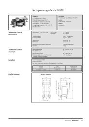
<strong>Inkremental</strong>-<strong>Drehgeber</strong> <strong>RI</strong> <strong>30</strong><br />
Vorwort<br />
Diese Installationsanleitung soll Ihnen den Anschluß und die Inbetriebnahme<br />
des <strong>Drehgeber</strong>s ermöglichen.<br />
Weitere Informationen finden Sie im <strong>Drehgeber</strong>katalog.<br />
Sicherheits- und Betriebshinweise<br />
• Die inkrementalen <strong>Drehgeber</strong> der Modellreihe <strong>RI</strong> <strong>30</strong> sind nach den anerkannten<br />
Regeln der Elektrotechnik hergestellte Qualitätsprodukte.<br />
Die Geräte haben das Herstellerwerk in sicherheitstechnisch einwandfreiem<br />
Zustand verlassen.<br />
Um diesen Zustand zu erhalten und um einen störungsfreien Betrieb sicherberücksichtigen.<br />
• Einbau und Montage elektrischer Geräte dürfen nur durch eine Elektrofachkraft<br />
erfolgen!<br />
• Die Geräte dürfen nur innerhalb der Grenzwerte betrieben werden, wie sie in<br />
den technischen Daten vorgegeben sind.<br />
• Die maximalen Betriebsspannungen dürfen nicht überschritten werden!<br />
Die Geräte sind nach VDE 0160, Schutzklasse III gebaut.<br />
Sie müssen zur Verhinderung von gefährlichen Körperströmen mit Sicherheitskleinspannung<br />
(SELV) betrieben werden und sich in einem Bereich mit<br />
Mechanische Daten<br />
<strong>Hengstler</strong> <strong>GmbH</strong><br />
Postfach 11 5 1 Tel. 07424 – 890<br />
D-78554 Aldinge n Fax 07424 – 89370<br />
Befestigung Synchroflansch 1) , Rundflansch 1)<br />
Wellendurchmesser<br />
5 mm<br />
Wellenbelastung<br />
radial 10 N, axial 5 N<br />
Drehzahl max. 10000 min -1<br />
Drehmoment ≤ 1 Ncm (IP 64)<br />
Schutzart Welle/Gehäuse IP 40/65, IP 64 2) /65<br />
Betriebstemperatur –10 … +70 °C<br />
Lagertemperatur –25 … +85 °C<br />
Schwingfestigkeit (IEC 68-2-6) 100 m/s 2 (10 … 2000 Hz)<br />
Schockfestigkeit (IEC 68-2-27) 1000 m/s 2 (6 ms)<br />
Anschlußart<br />
Kabel axial/radial, Binder axial<br />
Gehäuse<br />
Masse<br />
Aluminium<br />
ca. 60 g<br />
1)<br />
Befestigung mit M3-Schrauben<br />
2)<br />
stehendes Wasser am Welleneingang oder Kugellager nicht zulässig<br />
• Anwendungsbereich: industrielle Prozesse und Steuerungen.<br />
Überspannungen an den Anschlußklemmen müssen auf Werte der Überspannungskategorie<br />
II begrenzt werden.<br />
• Vermeiden Sie die Einwirkung von Schocks auf das Gehäuse – vor allem auf<br />
die Geberwelle – sowie axiale und radiale Überlastungen der Geberwelle.<br />
• Die maximale Genauigkeit und Lebensdauer der Geber wird nur bei Verwendung<br />
einer geeigneten Kupplung garantiert.<br />
• Die guten EMV-Werte gelten nur in Verbindung mit den serienmäßig gelieferten<br />
Kabeln und Steckern. Bei geschirmten Kabeln ist der Schirm beidseitig<br />
versorgung sollten vollständig geschirmt sein. Ist dies nicht möglich, so sind<br />
entsprechende Filtermaßnahmen zu ergreifen.<br />
•<br />
EMV des Gebers, so daß vom Installateur die EMV der gesamten Anlage<br />
(Gerät) sicherzustellen ist.<br />
• Nach Norm EN 61326-1:2006(Tabelle 2) werden Gleichspannungsverbindungen<br />
wie Eingangs-/ Ausgangssignalleitungen behandelt.<br />
Bei Kabellängen größer <strong>30</strong> m oder Anwendungen außerhalb von Gebäuden<br />
sind zusätzliche Maßnahmen zur Einhaltung der EMV erforderlich.<br />
• In elektrostatisch gefährdeten Bereichen ist bei der Installation auf einen<br />
guten ESD-Schutz für Stecker und anzuschließendes Kabel zu achten.<br />
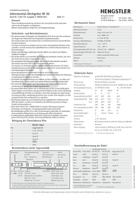
Belegung der Flanschdosen-Pins<br />
Binder 6pol.<br />
Pin<br />
Gegentakt (K)<br />
1 5 /10…<strong>30</strong> V DC<br />
2 Kanal A<br />
3 Kanal N<br />
4 Kanal B<br />
5 Alarm<br />
6 GND<br />
Bestellschlüssel (siehe Typenschild)<br />
O Standard<br />
Versorgungsspannung<br />
A 5 VDC<br />
E 10 … <strong>30</strong> VDC (nur<br />
Gegentakt)<br />
Flanschart<br />
S Synchroflansch<br />
R Rundflansch<br />
R I 3 0 – 0 / · 4<br />
Strichzahl<br />
5 … 1500<br />
Schutzart<br />
1 IP 50<br />
3 IP 64<br />
Ausgang<br />
T RS 422 + Sense<br />
K Gegentakt kurzschlußfest<br />
R RS 422 + Alarm<br />
D Gegentakt 5 V, <strong>30</strong> mA<br />
Wellendurchmesser<br />
4 5 mm<br />
Anschlußart A PVC-Kabel, axial<br />
B PVC-Kabel, radial<br />
E TPE-Kabel, axial<br />
F TPE-Kabel, radial<br />
N Binder, 6pol. axial<br />
* Sonderausführungen sind im Bestellschlüssel zusätzlich mit -S gekennzeichnet.<br />
In diesem Fall gelten kundenspezifische Daten. Sollten Ihnen diese nicht bekannt sein, so fordern Sie die<br />
Daten bitte unter Angabe der Geber-Sachnummer bei uns an.<br />
*<br />
Elektrische Daten<br />
Allgemeine Auslegung<br />
Abschirmung<br />
Stromaufnahme<br />
Anschlußbenennung der Kabel<br />
gemäß DIN VDE 0160, Schutzklasse III,<br />
Ausgangsschaltung<br />
Farbe (TPE) Farbe (PVC) RS 422 (T) RS 422 (R) Gegentakt (K, D)<br />
braun weiß Kanal A Kanal A Kanal A<br />
grün weiß/braun Kanal A Kanal A<br />
grau grün Kanal B Kanal B Kanal B<br />
rosa grün/braun Kanal B Kanal B<br />
rot gelb Kanal N Kanal N Kanal N<br />
schwarz gelb/braun Kanal N Kanal N<br />
violett (weiß) 2) gelb/schwarz Sense GND Alarm Alarm<br />
blau gelb/rot Sense V CC<br />
Sense V CC<br />
braun/grün rot<br />
3)<br />
5 V DC<br />
3)<br />
5/10…<strong>30</strong> V DC<br />
3)<br />
5/10…<strong>30</strong> V DC<br />
weiß/grün schwarz GND GND GND<br />
Kabelschirm 1) Kabelschirm 1) Kabelschirm 1) Kabelschirm 1) Kabelschirm 1)<br />
1)<br />
mit dem Gebergehäuse verbunden<br />
2)<br />
weiß bei Ausführung Sense (T)<br />
3)<br />
bei DC 5V max. Kabellänge <strong>30</strong>m<br />
Technische Änderungen und Verbesserungen, die dem Fortschritt unserer Geräte dienen, behalten wir uns vor.<br />
Verschmutzungsgrad 2, Überspannungskategorie II<br />
Mit dem Gehäuse verbunden<br />
5V/40 mA, 24V/<strong>30</strong> mA (10...<strong>30</strong> V), 10V/60 mA (10...<strong>30</strong>V)<br />
Versorgungsspannung U B<br />
2)<br />
5 V DC (SELV) ±10% 10 ... <strong>30</strong> V DC (SELV)<br />
Ausgang 1) GT GT RS422 GT<br />
Kennbuchstabe K D R, T K<br />
Ausgangsbelastung [mA] ±10 ±<strong>30</strong> ±<strong>30</strong> ±<strong>30</strong><br />
Ausgangspegel [V] High ≥2,5 ≥2,5 ≥2,5 U B<br />
-3<br />
Low ≤0,5 ≤0,5 ≤0,5 ≤2<br />
Schaltzeiten [ns] 250 100 100 2000<br />
max. Impulsfrequenz [kHz] <strong>30</strong>0 <strong>30</strong>0 <strong>30</strong>0 200<br />
Verpolschutz ja nein nein ja<br />
Kurzschlußfestigkeit ja 1 Kanal 1 Kanal ja<br />
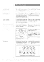
Tastverhältnis 1 : 1<br />
Toleranz<br />
Phasenversatz<br />
Impulsform<br />
± 25° elektrisch<br />
90° (zwischen Kanal A und B min. 0,45 µs, bei <strong>30</strong>0 kHz)<br />
Rechteck<br />
Alarm-Ausgang offener Kollektor, NPN (bei U B<br />
=5 VDC: max. 5 mA, 24 V;<br />
1)<br />
GT=Gegentakt; RS422=Line driver<br />
bei U B<br />
=10...<strong>30</strong> VDC: max. 5 mA, 32 V)<br />
2) bei DC 5V max. Kabellänge <strong>30</strong>m<br />
Sach-Nr. 2 520 124, 3 200709HOR
Installation instructions<br />
Incremental Shaft Encoder <strong>RI</strong> <strong>30</strong><br />
Introduction<br />
These installation instructions are provided for the connection and starting<br />
procedure of your shaft encoder.<br />
For further informations see our Shaft Encoders Catalogue.<br />
Safety and Operating Instructions<br />
• The incremental shaft encoders of the type <strong>RI</strong> <strong>30</strong> model series are quality<br />
products manufactured in accordance with established electrical engineering<br />
standards.<br />
The units have been delivered from the factory in perfect conformance to<br />
safety regulations.<br />
To maintain this condition and to ensure trouble-free operation, please ob-<br />
• Installation and mounting may only be performed by an electrotechnical<br />
expert!<br />
•<br />
data.<br />
• Maximum operating voltages must not be exceeded!<br />
The units are designed complying with VDE 0160, protection class III.<br />
To prevent dangerous structure-borne currents, the equipment has to be run<br />
on safety extra-low voltage (SELV) and must be in an area of equipotential<br />
bonding.<br />
• Application: Industrial processes and control systems.<br />
Overvoltage at the connecting terminals must be limited to the values within<br />
overvoltage category II.<br />
• Please avoid shocks to the housing – especially to the encoder shaft – and<br />
axial or radial overload to the encoder shaft.<br />
• Maximum accuracy and durability of our shaft encoders is only granted<br />
when using suitable couplings.<br />
•<br />
type cables and plugs. When using screened cables, the screen must broadly<br />
be connected with ground on both ends. Likewise, the voltage-supply cables<br />
should entirely be screened. If this is not possible you will have to take<br />
•<br />
Thus the installer must secure EMC of the whole facility (device).<br />
• According to Norm EN 61326-1: 2006 (chart 2) DC supply connections to<br />
the encoder are treated as input/ output signal lines. For cable lengths<br />
greater than <strong>30</strong> m and outdoor applications additional measures must be<br />
implemented in order to comply with CE<br />
• In electrostaticly threatened areas please take care for neat ESD-protection<br />
of plug and connecting cable during installation work.<br />
Pinout of connector<br />
Binder 6 poles<br />
Pin<br />
Push-pull (K)<br />
1 5 /10…<strong>30</strong> V DC<br />
2 Channel A<br />
3 Channel N<br />
4 Channel B<br />
5 Alarm<br />
6 GND<br />
Ordering data (see identification plate)<br />
O Standard<br />
Supply voltage<br />
A 5 VDC<br />
E 10 … <strong>30</strong> VDC (Push-pull<br />
only)<br />
Type of flange<br />
S synchro flange<br />
R round flange<br />
R I 3 0 – 0 / · 4<br />
Resolution<br />
5 … 1,500<br />
Protection class<br />
1 IP 50<br />
3 IP 64<br />
Output<br />
T RS 422 + Sense<br />
K Push-pull short circuit proof<br />
R RS 422 + Alarm<br />
D Push-pull 5 V, <strong>30</strong> mA<br />
Shaft<br />
diameter<br />
4 5 mm<br />
Type of connectionA cable PVC, axial<br />
B cable PVC, radial<br />
E cable TPE, axial<br />
F cable TPE, radial<br />
N Binder, 6 poles, axial<br />
* Special types are additionally marked by an ordering code -S.<br />
In this case customer specifications are to be applied. If you don’t know these please call us for the<br />
specifications, indicating the encoder ordering code.<br />
*<br />
Mechanical data<br />
Technical specifications subject to change without notice.<br />
<strong>Hengstler</strong> <strong>GmbH</strong><br />
Postfach 11 5 1 Tel. 07424 – 890<br />
D-78554 Aldinge n Fax 07424 – 89370<br />
Mounting synchro flange 1) , round flange 1)<br />
Shaft diameter<br />
5 mm<br />
Absolute max. shaft load radial <strong>30</strong> N (6.5 lbs), axial 15 N (3.3 lbs)<br />
Maximum speed<br />
max. 10,000 RPM<br />
Torque ≤ 1 Ncm (IP 64)<br />
Protection class (EN 60529) IP 40/65, IP 64 2) /65<br />
Operating temperature –10 … +70 °C<br />
Storage temperature –25 … +85 °C<br />
Vibration performance (IEC 68-2-6)100 m/s 2 (10 … 2,000 Hz)<br />
Shock resistance (IEC 68-2-27) 1,000 m/s 2 (6 ms)<br />
Connection<br />
cable axial/radial, Binder axial<br />
Housing<br />
aluminium<br />
Weight<br />
60 g approx.<br />
Bearing life 1 x 10 10 revolutions (typ.) at 35% of full rated shaft load<br />
1 x 10 9 revolutions (typ.) at 75% of full rated shaft load<br />
1 x 10 8 revolutions (typ.) at 100% of full rated shaft load<br />
For example <strong>30</strong>,000 h at 6,000 RPM with a 2 lb radial load<br />
1)<br />
use threads M3 for fastening<br />
2)<br />
no standing water allowed at he shaft entrance or at the ball bearing<br />
Electrical data<br />
General design<br />
as per DIN VDE 0160, protection class III,<br />
contamination level 2, overvoltage class II<br />
Screening<br />
connected to housing<br />
Power consumption 5V/40 mA, 24V/<strong>30</strong> mA (10...<strong>30</strong> V), 10V/60 mA (10...<strong>30</strong>V)<br />
Supply voltage U B<br />
(SELV)<br />
2)<br />
5 V DC ±10% 10...<strong>30</strong> VDC<br />
Output circuit 1) PP PP RS422 PP<br />
Code letter K D R, T K<br />
Output load [mA] ±10 ±<strong>30</strong> ±<strong>30</strong> ±<strong>30</strong><br />
Output voltage [V] High ≥2.5 ≥2.5 ≥2.5 U B<br />
-3<br />
Low ≤0.5 ≤0.5 ≤0.5 ≤2<br />
Pulse rise time [ns] 250 100 100 2000<br />
Max. pulse frequency [kHz] <strong>30</strong>0 <strong>30</strong>0 <strong>30</strong>0 200<br />
Reverse polarity protection yes no no yes<br />
Short-circuit protection yes 1 channel 1 channel yes<br />
Pulse duty factor 1 : 1<br />
Pulse width error ± 25° electrical<br />
Phase shift<br />
90° (distance from Channel A to B is at least<br />
0.45 µs, at <strong>30</strong>0 kHz)<br />
Pulse shape<br />
rectangular<br />
Alarm output Open Collector, NPN (with U B<br />
=5 VDC: max. 5 mA, 24 V;<br />
with U B<br />
=10...<strong>30</strong> VDC: max. 5 mA, 32 V)<br />
1)<br />
PP=Push-pull; RS422=Line driver<br />
2)<br />
at DC 5V cable length max. <strong>30</strong>m<br />
Connection diagram cable<br />
Output<br />
Colour (TPE) Colour (PVC) RS 422 (T) RS 422 (R) Push-pull (K, D)<br />
brown white Channel A Channel A Channel A<br />
green white/brown Channel A Channel A<br />
grey green Channel B Channel B Channel B<br />
pink green/brown Channel B Channel B<br />
red yellow Channel N Channel N Channel N<br />
black yellow/brownChannel N Channel N<br />
violet (white) 2) yellow/black Sense GND Alarm Alarm<br />
blue yellow/red Sense V CC<br />
Sense V CC<br />
brown/green red<br />
3)<br />
5 V DC<br />
3)<br />
5/10…<strong>30</strong> V DC<br />
3)<br />
5/10…<strong>30</strong> V DC<br />
white/green black GND GND GND<br />
Screen 1) Screen 1) Screen 1) Screen 1) Screen 1)<br />
1)<br />
connected to encoder housing<br />
3)<br />
at DC 5V cable length <strong>30</strong>m max.<br />
2)<br />
white for Sense (T)<br />
Item No. 2 520 124, 3 200709HOR