
Create successful ePaper yourself
Turn your PDF publications into a flip-book with our unique Google optimized e-Paper software.
SINGLE-CHANNEL<br />
SHAFT ENCODERS<br />
TWO-CHANNEL<br />
SHAFT ENCODERS<br />
THREE-CHANNEL<br />
SHAFT ENCODERS<br />
HENGSTLER SHAFT ENCODERS<br />
OUTPUT SIGNALS<br />
EVALUATION<br />
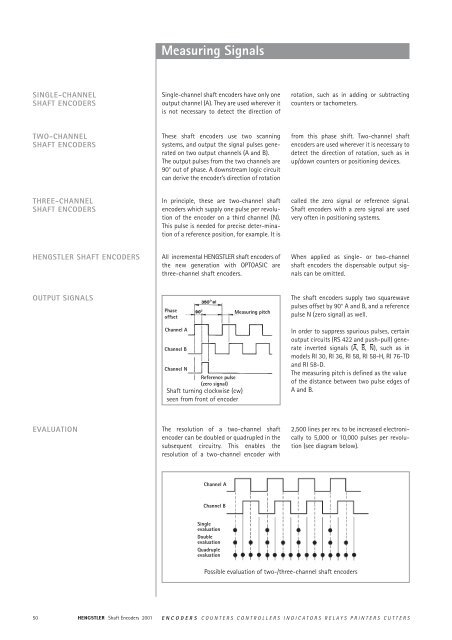
Measuring Signals<br />
Single-channel shaft encoders have only one<br />
output channel (A). They are used wherever it<br />
is not necessary to detect the direction of<br />
These shaft encoders use two scanning<br />
systems, and output the signal pulses generated<br />
on two output channels (A and B).<br />
The output pulses from the two channels are<br />
90° out of phase. A downstream logic circuit<br />
can derive the encoder’s direction of rotation<br />
In principle, these are two-channel shaft<br />
encoders which supply one pulse per revolution<br />
of the encoder on a third channel (N).<br />
This pulse is needed for precise deter-mination<br />
of a reference position, for example. It is<br />
All incremental HENGSTLER shaft encoders of<br />
the new generation with OPTOASIC are<br />
three-channel shaft encoders.<br />
Phase<br />
offset<br />
Channel A<br />
Channel B<br />
Channel N<br />
Reference pulse<br />
(zero signal)<br />
Shaft turning clockwise (cw)<br />
seen from front of encoder<br />
The resolution of a two-channel shaft<br />
encoder can be doubled or quadrupled in the<br />
subsequent circuitry. This enables the<br />
resolution of a two-channel encoder with<br />
Channel A<br />
Channel B<br />
Single<br />
evaluation<br />
Double<br />
evaluation<br />
Quadruple<br />
evaluation<br />
Measuring pitch<br />
rotation, such as in adding or subtracting<br />
counters or tachometers.<br />
from this phase shift. Two-channel shaft<br />
encoders are used wherever it is necessary to<br />
detect the direction of rotation, such as in<br />
up/down counters or positioning devices.<br />
called the zero signal or reference signal.<br />
Shaft encoders with a zero signal are used<br />
very often in positioning systems.<br />
When applied as single- or two-channel<br />
shaft encoders the dispensable output signals<br />
can be omitted.<br />
The shaft encoders supply two squarewave<br />
pulses offset by 90° A and B, and a reference<br />
pulse N (zero signal) as well.<br />
In order to suppress spurious pulses, certain<br />
output circuits (RS 422 and push-<strong>pull</strong>) generate<br />
inverted signals (A, B, N), such as in<br />
models RI 30, RI 36, RI 58, RI 58-H, RI 76-TD<br />
and RI 58-D.<br />
The measuring pitch is defined as the value<br />
of the distance between two pulse edges of<br />
A and B.<br />
2,500 lines per rev. to be increased electronically<br />
to 5,000 or 10,000 pulses per revolution<br />
(see diagram below).<br />
Possible evaluation of two-/three-channel shaft encoders<br />
50 Shaft Encoders 2001 ENCODERS COUNTERS CONTROLLERS INDICATORS RELAYS PRINTERS CUTTERS
Maximum Speed, Protection Class<br />
SPEED The maximum permissible speed of a shaft<br />
encoder is derived from:<br />
PROTECTION CLASS<br />
• the mechanically permissible r.p.m,<br />
• the minimum permissible pulse-edge<br />
spacing of the square-wave output signals<br />
of the shaft encoder for the subsequent<br />
circuitry, which depends on the<br />
tolerance of the phase offset,<br />
• the functional speed, which is limited by<br />
the pulse frequency.<br />
The mechanically permissible r.p.m. is specified<br />
for each shaft encoder among the<br />
mechanical characteristics.<br />
In general, the control circuitry does not permit<br />
less than a certain minimum edge spacing<br />
between the square-wave output signal<br />
pulses. The minimum pulse-edge spacing is<br />
specified for each model of shaft encoder<br />
among the electrical characteristics.<br />
All encoders of the industrial types RI 30,<br />
RI 36, RI 58, RI 58-H, RI 58-D, RX 70-I as<br />
well as the absolute encoders RA 58, comply<br />
with protection class IP 65 according to EN<br />
60529 and IEC 529, unless otherwise stated.<br />
These specifications are valid for the housing<br />
and the cable output and also for plugged in<br />
socket connectors.<br />
The shaft input complies with protection<br />
class IP 64. If however the encoder is mounted<br />
vertically, there must be no standing<br />
water present at the shaft input and the ball<br />
bearings.<br />
The functional speed of an encoder is obtained<br />
by the equation:<br />
n max =f max · 10 3 · 60 / Z<br />
nmax = maximum functional speed [r.p.m.]<br />
f max = maximum pulse frequency of shaft<br />
encoder, or input frequency of downstream<br />
circuitry [kHz]<br />
z = number of pulses of shaft encoder<br />
ENCODERS COUNTERS CONTROLLERS INDICATORS RELAYS PRINTERS CUTTERS Shaft Encoders 2001<br />
RPM<br />
Number<br />
of<br />
pulses<br />
Maximum permissible speed as a function of number of<br />
pulses and signal frequency of shaft encoder<br />
In case the standard protection class IP 64 is<br />
not sufficient for the shaft input, e.g. with<br />
vertical mounting of the encoder, the encoders<br />
must be protected by additional labyrinth<br />
or pot-type seals. On request our encoders<br />
are also available with protection class<br />
IP 67 for the shaft input and for the housing.<br />
51
FLANGE TYPE OVERVIEW<br />
SHAFT ENCODERS<br />
WITH CLAMPING FLANGE<br />
Examples of Flange Mounting<br />
S = Synchro flange<br />
Q = Square flange<br />
K =Clamping flange<br />
R = Round flange<br />
The shaft encoders with a clamping flange can be installed in following ways:<br />
• by means of various flange adapters (see “Accessories”),<br />
• by means of the clamping flange itself,<br />
• by means of the fastening threads provided on the face,<br />
• by means of an angle bracket (see Accessories”).<br />
The encoder housing is centered by means of the clamping flange.<br />
Flange adapter Clamping flange<br />
Mounting by fastening threads Mounting by angle bracket<br />
52 Shaft Encoders 2001 ENCODERS COUNTERS CONTROLLERS INDICATORS RELAYS PRINTERS CUTTERS
SHAFT ENCODERS<br />
WITH SYNCHRO FLANGE<br />
SHAFT ENCODERS<br />
WITH SQUARE FLANGE<br />
SHAFT ENCODERS<br />
WITH ROUND FLANGE<br />
Examples of Flange Mounting<br />
The shaft encoders with synchro flange can be installed in two ways:<br />
• by means of the synchro flange and three clamping eccentrics (see “Accessories”),<br />
• by means of the fastening threads provided on the face.<br />
The encoder is centered by means of the centering collar on the flange.<br />
Clamping eccentric<br />
Mounting bell<br />
The shaft encoders with square flange can be installed in two ways:<br />
• by means of the fastening threads provided on the face,<br />
• by means of an angle bracket.<br />
The encoder is centered by means of the centering collar on the flange.<br />
Mounting by fastening threads<br />
The shaft encoders with round flange can be installed in two ways:<br />
• by means of the fastening threads provided on the face,<br />
• by means of an angle bracket.<br />
The encoder is centered by means of the centering collar on the flange.<br />
Angle bracket<br />
Mounting by fastening threads Angle bracket<br />
ENCODERS COUNTERS CONTROLLERS INDICATORS RELAYS PRINTERS CUTTERS Shaft Encoders 2001<br />
53
SHAFT ENCODERS<br />
WITH HOLLOW SHAFT<br />
(RI 58-H)<br />
SHAFT ENCODERS<br />
WITH HOLLOW SHAFT<br />
(RI 58-D/G)<br />
SHAFT ENCODERS WITH<br />
SOLID SHAFT<br />
Examples of Flange Mounting<br />
a) Mounting by screws<br />
1 Hollow-shaft encoder<br />
2 “B”-side of drive shaft<br />
3 Fastening screws (M4)<br />
Mounting of version F, D (Clamping shaft)<br />
1 Torque spring<br />
2 Clamping ring with cross-recess screw<br />
3 Straight pin<br />
4 Actuating shaft<br />
b) Mounting by clamping eccentrics<br />
1 Hollow-shaft encoder<br />
2 “B”-side of drive shaft<br />
3 Clamping eccentrics<br />
4 Fastening screws<br />
Mounting of version E (Blind shaft)<br />
1 Torque spring<br />
2 O-ring<br />
3 Straight pin<br />
4 Actuating shaft with threaded bore<br />
5 M4-screw with spring washer<br />
6 Cap<br />
Connection of solid-shaft encoders to the shaft is by means of a coupling.<br />
The coupling compensates for axial movements and lack of alignment between the shaft<br />
encoder and the drive shaft, thus preventing excessive bearing loads on the encoder shaft.<br />
For further details please refer to heading “Accessories”.<br />
54 Shaft Encoders 2001 ENCODERS COUNTERS CONTROLLERS INDICATORS RELAYS PRINTERS CUTTERS
OUTPUT CIRCUIT<br />
TECHNICAL DATA<br />
<strong>Output</strong><br />
RS 422<br />
Code Letter R = RS 422 + Alarm 3) (with UB = 5/10...30 VDC)<br />
T = RS 422 + Sense 4) (only with U B = 5 VDC)<br />
<strong>Output</strong> signals shaft<br />
turning clockwise (cw)<br />
seen from front<br />
of encoder<br />
Delay times<br />
at 1.5 m cable<br />
<strong>Output</strong> Recommended input circuitry<br />
1) Cable screen:<br />
- not existing for RI 32, 38, 42<br />
- connected to encoders housing for RI 30, 36, 58, 59, 76 and RX 70<br />
≤ 100 ns ≤ 100 ns<br />
Pulse shape<br />
Pulse duty factor 1:1<br />
Pulse width error 1) ± 25° electrical<br />
Max. pulse frequency 300 kHz<br />
<strong>Output</strong> voltage 0... + 5 VDC 2)<br />
<strong>Output</strong> level H ≥ 2.5 VDC/L ≤ 0.5 VDC (TTL-level)<br />
<strong>Output</strong> load max. ± 30 mA<br />
Short circuit protection with UB = 5 VDC: only 1 channel at a time for max. 1 s<br />
(standard RS 422-driver)<br />
with UB = 10...30 VDC: short circuit proof for all channels<br />
due to integrated controller<br />
Pole protection of UB with UB = 5 VDC: no<br />
with UB = 10...30 VDC: yes<br />
1) distance from A to B is at least 0.45 µs (at 300 kHz)<br />
2) also for UB = 10...30 VDC<br />
CABLE LENGTH depending on voltage and frequency (at 25°C) 1):<br />
length RS 422<br />
10 m 5 VDC, 300 kHz<br />
50 m 5 VDC, 300 kHz<br />
100 m 5 VDC, 300 kHz<br />
1) with respect to <strong>Hengstler</strong> own cables<br />
Square wave pulses<br />
(TTL) for channels A, B, N<br />
and their inverted<br />
signals A, B, N<br />
3) Description - see <strong>Output</strong>s-Alarm<br />
4) Description - see <strong>Output</strong>s-Sense<br />
ENCODERS COUNTERS CONTROLLERS INDICATORS RELAYS PRINTERS CUTTERS Shaft Encoders 2001<br />
55
OUTPUT CIRCUIT<br />
TECHNICAL DATA<br />
<strong>Output</strong><br />
<strong>Push</strong>-<strong>pull</strong><br />
Code Letter K = push-<strong>pull</strong>, 10 mA with U B = 5 VDC<br />
or push-<strong>pull</strong>, 30 mA with U B = 10...30 VDC<br />
D = push-<strong>pull</strong>, 30 mA with U B = 5 VDC<br />
<strong>Output</strong> signals shaft<br />
turning clockwise (cw)<br />
seen from front<br />
of encoder<br />
<strong>Output</strong> Recommended input circuitry<br />
1) Cable screen:<br />
- not existing for RI 32, 38, 42<br />
- RI 41, not connected to encoder housing<br />
- connected to encoders housing for RI 30, 36, 58, 59, 76 and RX 70<br />
Squarewave pulses<br />
(TTL or HTL) for<br />
channels A, B, N<br />
Delay times<br />
with 1.5 m Cable<br />
≤ 250 ns ≤ 250 ns<br />
Pulse shape<br />
Pulse duty factor 1:1<br />
Pulse width error 1) ± 25° electrical<br />
Max. pulse frequency 300 kHz (see cable length)<br />
<strong>Output</strong> voltage 0... + UB <strong>Output</strong> level K K D<br />
push-<strong>pull</strong> (10...30 V) push-<strong>pull</strong> (5 V) push-<strong>pull</strong> (5 V)<br />
H ≥ UB -3V H ≥ 2,5 V H ≥ 2,5 V<br />
L ≤ 2 V L ≤ 0,5 V L ≤ 0,5 V<br />
<strong>Output</strong> load max. ± 30 mA ± 10 mA ± 30 mA<br />
Short circuit protection all channels all channels 1 channel 2)<br />
Pole protection of UB with UB = 5 VDC: output K yes, output D no<br />
with UB = 10...30 VDC: yes<br />
1) Distance A to B min. 0.45 µs (at 300 kHz)<br />
2) only 1 channel at a time for max. 1 s<br />
CABLE LENGTH depending on voltage and frequency (at 25°C) 1):<br />
length push-<strong>pull</strong> (K) push-<strong>pull</strong> (D) push-<strong>pull</strong> (K)<br />
5 VDC, 10 mA 5 VDC, 30 mA 10...30 VDC, 30 mA<br />
10 m 300 kHz 300 kHz 12 VDC, 200 kHz<br />
24 VDC, 200 kHz<br />
30 VDC, 200 kHz<br />
50 m 300 kHz 12 VDC, 200 kHz<br />
24 VDC, 200 kHz<br />
30 VDC, 100 kHz<br />
100 m 300 kHz 12 VDC, 200 kHz<br />
24 VDC, 100 kHz<br />
30 VDC, 50 kHz<br />
1) with respect to <strong>Hengstler</strong> own cables<br />
56 Shaft Encoders 2001 ENCODERS COUNTERS CONTROLLERS INDICATORS RELAYS PRINTERS CUTTERS
TECHNICAL DATA<br />
CABLE LENGTH<br />
<strong>Output</strong><br />
<strong>Push</strong>-<strong>pull</strong> complementary<br />
Code Letter I = push-<strong>pull</strong> complementary (with U B = 10...30 V)<br />
<strong>Output</strong> signals shaft<br />
turning clockwise (cw)<br />
seen from front<br />
of encoder<br />
Delay times<br />
at 1.5 m cable<br />
output Recommended input circuitry<br />
1) Cable screen connected with encoder housing<br />
≤ 250 ns ≤ 250 ns<br />
Pulse shape<br />
Pulse duty factor 1:1<br />
Pulse width error 1) ± 25° electrical<br />
Max. pulse frequency 200 kHz (see cable length)<br />
<strong>Output</strong> voltage 0... + UB <strong>Output</strong> level H ≥ UB -3 V/L ≤ 2 V<br />
<strong>Output</strong> load max. ± 30 mA<br />
Short circuit protection short circuit proof for all channels<br />
due to integrated controller<br />
Pole protection of UB: yes<br />
1) distance from A to B is at least 0.7 µs (at 200 kHz)<br />
depending on voltage and frequency (at 25°C) 1):<br />
length push-<strong>pull</strong> complementary<br />
10 m 12 VDC, 200 kHz<br />
24 VDC, 200 kHz<br />
30 VDC, 200 kHz<br />
50 m 12 VDC, 200 kHz<br />
24 VDC, 50 kHz<br />
30 VDC, 25 kHz<br />
100 m 12 VDC, 150 kHz<br />
24 VDC, 25 kHz<br />
30 VDC, 12 kHz<br />
1) with respect to <strong>Hengstler</strong> own cables<br />
ENCODERS COUNTERS CONTROLLERS INDICATORS RELAYS PRINTERS CUTTERS Shaft Encoders 2001<br />
Square wave pulses<br />
(HTL) for channels A, B, N<br />
and their inverted<br />
signals A, B, N<br />
57
OUTPUT CIRCUIT<br />
TECHNICAL DATA<br />
FUNCTION<br />
<strong>Output</strong><br />
Alarm<br />
Encoder<br />
<strong>Output</strong> NPN - open collector<br />
<strong>Output</strong> load max. 5 mA/24 V at U B = 5 VDC<br />
5mA/32 V at U B = 10...30 VDC<br />
<strong>Output</strong> Level <strong>Output</strong> active (failure condition): L ≤ 0.7 VDC<br />
<strong>Output</strong> inactive: highohmic (if necessary: get H-level by<br />
an external <strong>pull</strong>-up resistor)<br />
Malfunction indication time ≥ 20 ms<br />
The rotary encoders are equipped with an electronic monitoring system which reports<br />
malfunctions via a separate alarm output.<br />
The alarm output can be used for selecting an optical display (LED; for circuit, see above) or<br />
the control system (SPC or similar).<br />
Moreover, the alarm outputs of several encoders can be interconnected to a common<br />
“systems alarm” by means of a parallel connection. The following malfunctions are indicated:<br />
Category I Category II Category III<br />
- damaged disks - overtemperature - voltage range<br />
1 VDC < U < 4 VDC<br />
- defective LED - overload (e. g. - voltage drop on the<br />
due to short circuit) supply lines<br />
- contamination<br />
Category I malfunctions cannot be corrected; the encoder must be replaced.<br />
Category II malfunctions are detected by means of a thermal monitoring unit in the electronic<br />
system. The alarm message is cleared after the cause of temperature increase has been<br />
removed.<br />
Category III malfunctions indicate insufficient supply voltage. Also included in this category<br />
are transients in the supply voltage, e.g. due to electrostatic discharge, which may distort the<br />
output signals.<br />
This is corrected by<br />
- readjustment to the correct voltage<br />
- eliminating the cause of disturbance, i.e. by careful arrangement of the cables.<br />
58 Shaft Encoders 2001 ENCODERS COUNTERS CONTROLLERS INDICATORS RELAYS PRINTERS CUTTERS
OUTPUT CIRCUIT<br />
FUNCTION<br />
<strong>Output</strong><br />
Sense at RS 422 (T)<br />
Encoder power pack<br />
1) Voltage drop due to long cable lengths<br />
2) Automatic readjustment of the output voltage<br />
(only for power packs with sense input)<br />
ENCODERS COUNTERS CONTROLLERS INDICATORS RELAYS PRINTERS CUTTERS Shaft Encoders 2001<br />
Senseinput<br />
The sense cables enable the measuring of the actual sensor voltage (no corruption due to voltage<br />
drop resulting from supply current and cable resistance).<br />
Due to the voltage drop in the cables and the voltage supply, the encoder input voltage U in is<br />
less than the power pack output voltage U out.<br />
The present input voltage U in is now output to the Sense V CC and Sense GND cables and<br />
returns as data to the power pack.<br />
The input resistance R i on the power pack should amount to at least 22 MOhm so that no voltage<br />
drop occurs on these cables.<br />
In case of power packs with sense input, it is now possible to readjust the output voltage U out<br />
automatically.<br />
59
Type<br />
RI 30, 32, 36, 38, 41, 42, 58, 59,<br />
RX 70, RI 76 4)<br />
Version<br />
D direct hollow shaft<br />
H hollow shaft with integrated coupling<br />
O standard<br />
T high temperature<br />
I incremental (only for RX 70)<br />
Number of pulses<br />
Supply voltage<br />
A 5 VDC<br />
E 10 …30 VDC<br />
Type of flange<br />
A synchro flange adapter<br />
C square flange adapter; 58 x 58 mm<br />
D synchro flange with continuous shaft, front clamping ring<br />
E synchro flange with blind shaft<br />
F synchro flange with clamping shaft<br />
G square flange adapter; 80 x 80 mm<br />
H synchro flange with continuous shaft, rear clamping ring<br />
K clamping flange (M3 fastening thread)<br />
L clamping flange (M4 fastening thread)<br />
M synchro clamping flange; Ø 63.5 mm<br />
Q square flange; 63.5 x 63.5 mm<br />
R round flange<br />
S synchro flange<br />
X special version<br />
Code Table<br />
for Incremental Shaft Encoders<br />
- / . - -<br />
<strong>Output</strong> D push-<strong>pull</strong> 5 V DC=, 30 mA<br />
I push-<strong>pull</strong>, complementary + Alarm<br />
K push-<strong>pull</strong>, short circuit proof + Alarm<br />
R RS 422 + Alarm<br />
T RS 422 + Sense<br />
X special version<br />
Shaft 0 4 mm<br />
1 6 mm<br />
2 10 mm<br />
3 7 mm<br />
4 5 mm<br />
5 6,35 mm<br />
6 9,52 mm<br />
7 12 mm<br />
Cable length 3) (unnecessary for standard: 1.5 m)<br />
D Ø = 3 m<br />
F Ø = 5 m<br />
K Ø = 10 m<br />
Connection<br />
A PVC cable, axial<br />
B PVC cable, radial<br />
C CONIN 1) 12 pole, axial, clockwise<br />
D CONIN 1) 12 pole, radial, clockwise<br />
E TPE cable, axial<br />
F TPE cable, radial<br />
G CONIN 1) 12 pole, axial, counter clockwise<br />
H CONIN 1) 12 pole, radial, counter clockwise<br />
J BINDER 1) – 6 pole radial<br />
K MIL 1) – 10 pole radial<br />
L MIL 1) 7 pole, radial<br />
M MIL 1) 6 pole, axial<br />
N BINDER 1) 6 pole, axial<br />
O MIL 1) 10 pole, axial<br />
P MIL 1) 7 pole, axial<br />
Q MIL 1) 6 pole, radial<br />
R MIL 1) 10 pole, US axial<br />
T MIL 1) 10 pole, US radial<br />
1 KPT 1) 12-8P, axial<br />
2 KPT 1) 12-8P, radial<br />
X special version<br />
Protection class 1 IP 40 (housing IP 50) 7 IP 67 (housing IP 67)<br />
3 IP 64 (housing IP 64) X special version<br />
4 IP 64 (housing IP 65)<br />
1) CONIN, BINDER, MIL and KPT indicate the connectors with pins on the encoder housing<br />
2) only for connection of TPE cable (E, F)<br />
3) only with connection cable (A, B, E, F) and differing from standard (1.5 m resp. 1.0 m + plug)<br />
special lengths for larger quantities on request.<br />
4) e.g. RI 76 see section RI 76<br />
Example: RI 58-H/5000ES.37KB-D0<br />
Type: RI 58-H<br />
Number of pulses: 5,000<br />
E: Supply voltage: 10...30 VDC=<br />
S: Type of flange: Synchro flange<br />
3: Protection class: IP 64<br />
7: Shaft diameter: 12 mm<br />
K: <strong>Output</strong> circuit: push-<strong>pull</strong> short circuit proof + Alarm<br />
B: Type of connection: PVC cabel, radial<br />
D0: Cable length: 3.0 m<br />
Connector 2)<br />
(unnecessary for standard: cable with tinned lead)<br />
A Souriau coupling, socket<br />
B VDW connector, right-turning, pins<br />
C CONIN connector, right-turning, pins<br />
D CONIN coupling, left-turning, pins<br />
E VDW coupling, left-turning, pins<br />
S special version<br />
8 6 x 19,5 mm<br />
9 14 mm<br />
A = 10 mm x 25 mm<br />
B = 9,52 mm x 25 mm<br />
C = 8 mm<br />
D = 15 mm<br />
X special version<br />
60 Shaft Encoders 2001 ENCODERS COUNTERS CONTROLLERS INDICATORS RELAYS PRINTERS CUTTERS