XPM 200HR™ v1 - Hengstler GmbH
XPM 200HR™ v1 - Hengstler GmbH
XPM 200HR™ v1 - Hengstler GmbH

Create successful ePaper yourself
Turn your PDF publications into a flip-book with our unique Google optimized e-Paper software.
®<br />
Operating Manual<br />
<strong>XPM</strong> 200HR <strong>v1</strong><br />
Thermal Printer Family<br />
E<br />
Part No. D 690 074 Version 1.02 Mod. No. 4 300113 LEV
<strong>XPM</strong> 200HR Thermal Printer Family HENGSTLER ®<br />
© 2013 by HENGSTLER <strong>GmbH</strong><br />
<strong>Hengstler</strong> <strong>GmbH</strong> has created the text and diagrams contained in this document with care. However,<br />
we cannot accept responsibility for any errors or omissions. Notification regarding any errors and<br />
suggestions for improvement are welcome. We reserve the right to make technical and other<br />
changes at any time in the interest of continual product development.<br />
All information contained in this manual is provided without regard to any possible patent protection.<br />
All rights reserved. Reproduction, translation and/or distribution of this document, or extracts thereof,<br />
are permitted only by express authorization from <strong>Hengstler</strong> <strong>GmbH</strong>. The <strong>Hengstler</strong> name and the<br />
<strong>Hengstler</strong> logo are registered trademarks of <strong>Hengstler</strong> <strong>GmbH</strong>. “Windows” and “Microsoft” are<br />
registered trademarks of Microsoft Corporation. Other brand and product names are trademarks or<br />
registered trademarks of their respective companies.<br />
HENGSTLER <strong>GmbH</strong><br />
Uhlandstrasse 49<br />
78554 Aldingen / Germany<br />
Tel. +49 (0) 7424-89 0<br />
Fax +49 (0) 7424-89 500<br />
eMail: info@hengstler.com<br />
www.hengstler.com<br />
Part No. D 690 074 Mod. No. 4 300113 LEV page 2 of 32
<strong>XPM</strong> 200HR Thermal Printer Family HENGSTLER ®<br />
Document History<br />
Revision Date Initials Status Description<br />
1.00 2012 May 10 CBL Closed Initial version<br />
1.01 2013 Jan 28 CBL Closed Reduced paper weight to 80 g/m²<br />
1.02 2013 Jan 30 CBL Closed Revised paper weight to 80-100 g/m²; cleaned up<br />
other unfinished areas.<br />
Part No. D 690 074 Mod. No. 4 300113 LEV page 3 of 32
<strong>XPM</strong> 200HR Thermal Printer Family HENGSTLER ®<br />
Table of Contents<br />
1. Introduction ................................................................................................................................ 6<br />
1.1. Scope ................................................................................................................................ 6<br />
1.2. Additional Documentation ................................................................................................... 6<br />
2. Important Information and Safety Instructions ............................................................................. 7<br />
2.1. General Information ............................................................................................................ 7<br />
2.2. Systems Specific Safety Instructions and Symbols ............................................................. 8<br />
3. Overview .................................................................................................................................... 8<br />
3.1. Overview of Thermal Printing Technology ........................................................................... 8<br />
3.2. Functional View .................................................................................................................. 9<br />
3.3. Description of Components and Operation ....................................................................... 10<br />
3.4. Location of Controls and Connectors ................................................................................ 12<br />
3.5. Operation of Controls, Sensors and LEDs ........................................................................ 13<br />
3.5.1. Printer Access Control .............................................................................................. 13<br />
3.5.2. Paper Guides ........................................................................................................... 14<br />
3.5.3. Paper Entrance / Black Mark Sensor ........................................................................ 14<br />
3.5.4. “Printhead Raised” Sensor ........................................................................................ 15<br />
3.5.5. Cutter Sensors ......................................................................................................... 15<br />
3.5.6. Paper Exit Sensor ..................................................................................................... 15<br />
3.5.7. Paper Pre-End (Paper Low) Sensors ........................................................................ 15<br />
3.5.8. LED Indicators .......................................................................................................... 17<br />
3.6. Graphic Printing vs. Printing with Printer’s Fonts ............................................................... 17<br />
4. Unpacking ................................................................................................................................ 18<br />
5. Major Options ........................................................................................................................... 18<br />
5.1. Presenter ......................................................................................................................... 18<br />
6. Installation ................................................................................................................................ 19<br />
6.1. Function ........................................................................................................................... 19<br />
6.2. Mounting Printer ............................................................................................................... 19<br />
6.3. Mounting Controller .......................................................................................................... 20<br />
6.4. Wiring .............................................................................................................................. 21<br />
6.4.1. Power ....................................................................................................................... 21<br />
6.4.2. Interfacing ................................................................................................................ 22<br />
6.5. Paper Supply ................................................................................................................... 22<br />
6.5.1. Paper Roll Holder ..................................................................................................... 22<br />
6.6. Power Supply Specifications ............................................................................................ 23<br />
7. Operation ................................................................................................................................. 23<br />
7.1. Loading Paper .................................................................................................................. 23<br />
7.2. Print Speed ...................................................................................................................... 24<br />
7.3. Cutter Operation ............................................................................................................... 24<br />
7.4. Print Density ..................................................................................................................... 24<br />
7.5. Invalidation ....................................................................................................................... 24<br />
7.6. <strong>XPM</strong> 200HR Digital Tools ............................................................................................. 25<br />
8. Low Current Operation.............................................................................................................. 25<br />
8.1. Print Speed ...................................................................................................................... 25<br />
8.2. Graphics/Bar Codes ......................................................................................................... 26<br />
8.3. Reverse Printing ............................................................................................................... 26<br />
8.4. Dot History Factor ............................................................................................................ 26<br />
8.5. Burn Time Correction ....................................................................................................... 26<br />
8.6. Multi-Strobe Factor ........................................................................................................... 26<br />
8.7. Print Density Adjustment .................................................................................................. 26<br />
9. Troubleshooting ........................................................................................................................ 27<br />
10. Maintenance ........................................................................................................................ 27<br />
11. Repair .................................................................................................................................. 28<br />
12. Buying Paper ....................................................................................................................... 28<br />
12.1. Sourcing Paper ................................................................................................................ 28<br />
12.2. Converting Paper ............................................................................................................. 28<br />
12.3. Black Mark Sensor Location ............................................................................................. 28<br />
13. Technical Specifications ....................................................................................................... 31<br />
13.1. Electromagnetic Compatibility........................................................................................... 32<br />
Part No. D 690 074 Mod. No. 4 300113 LEV page 4 of 32
<strong>XPM</strong> 200HR Thermal Printer Family HENGSTLER ®<br />
13.1.1. FCC Part 15 Class B Device ..................................................................................... 32<br />
13.1.2. EN55022 – Emissions .............................................................................................. 32<br />
13.1.3. EN55024 – Electromagnetic Susceptibility ................................................................ 32<br />
13.2. Printer Drawings ............................................................................................................... 32<br />
Part No. D 690 074 Mod. No. 4 300113 LEV page 5 of 32
<strong>XPM</strong> 200HR Thermal Printer Family HENGSTLER ®<br />
1. Introduction<br />
Thank you for selecting the <strong>Hengstler</strong> <strong>XPM</strong> 200HR thermal printer! We are proud of this feature-rich<br />
product, which was designed using all our expertise and experience, and we are confident that you<br />
will be pleased with the advanced features and outstanding performance.<br />
This Operator Manual is designed to help you with the proper installation, connection to your host<br />
computer system and start-up of the <strong>XPM</strong> 200HR thermal printer system. All necessary details will<br />
be explained in the following sections. Please read this manual carefully before using the printer. If<br />
you have any further questions, please do not hesitate to contact us.<br />
The <strong>XPM</strong> 200HR thermal printer family does not require any servicing and is intended primarily for<br />
printing and cutting documents and receipts from continuous or fanfold thermal paper. The <strong>XPM</strong><br />
200HR handles paper with a width of 210 to 220 mm. A cutter is standard and is integrated into<br />
every <strong>XPM</strong> 200HR print mechanism. Powerful motors allow the use of large paper rolls to<br />
maximize time between paper replenishment. 'Black Mark' control is available for when documents<br />
are to be printed on preprinted forms or with a predetermined length. The <strong>XPM</strong> 200HR has a print<br />
resolution of 300 dpi to ensure that graphics, such as logos etc. can be printed with excellent quality.<br />
The printer is available with or without a presenter.<br />
The <strong>XPM</strong> 200HR printer family has been designed for use primarily in kiosks and similar information<br />
or ticket printing applications. Its robust design makes it a natural choice for such heavy-usage<br />
applications.<br />
Equipped with either USB or Serial (RS-232) interfaces, the <strong>XPM</strong> 200HR printer family is versatile<br />
and flexible! Driver software is available that supports Windows 7, Windows XP and Linux operating<br />
systems. In addition, these printers can also be activated directly through ESC sequences; a detailed<br />
description of the different native commands is contained in the <strong>XPM</strong> 200HR Emulation Command<br />
Set Reference.<br />
We’re glad you chose the <strong>XPM</strong> 200HR thermal printer family. Once you’ve used it, we’re sure you<br />
will be, too!<br />
1.1. Scope<br />
This manual covers the <strong>XPM</strong> 200HR thermal print mechanism, with or without presenter, and<br />
the related printer controller.<br />
1.2. Additional Documentation<br />
Document No.<br />
D 690 004<br />
D 690 005<br />
Description<br />
<strong>XPM</strong> 200HR Emulation Command Set<br />
Reference<br />
<strong>XPM</strong> 200HR Windows ® XP/7 Driver Manual<br />
D 690 008<br />
D 690 xxx<br />
D 690 075<br />
<strong>XPM</strong> 200HR Linux Driver Manual<br />
<strong>XPM</strong> 200HR Paper Specification<br />
<strong>XPM</strong> 200HR Dimensional Drawing<br />
Part No. D 690 074 Mod. No. 4 300113 LEV page 6 of 32
<strong>XPM</strong> 200HR Thermal Printer Family HENGSTLER ®<br />
2. Important Information and Safety Instructions<br />
<strong>Hengstler</strong> <strong>GmbH</strong> accepts no liability for any damages, direct, indirect or consequential, arising from<br />
improper use of this thermal printer, and, in particular, due to non-compliance with this operating<br />
manual or any other available documentation or due to improper handling or maintenance. Should<br />
<strong>Hengstler</strong> <strong>GmbH</strong> choose to make technical documentation available, this does not imply any<br />
authorization, implied or stated, for the making additions, repairs or modifications to this printer.<br />
This documentation may not be copied, nor shall its contents be disclosed or used commercially<br />
unless such use has otherwise been explicitly agreed to by a duly authorized <strong>Hengstler</strong> representative<br />
in writing.<br />
The user is responsible for proper handling and installation of this printer. The printer should only be<br />
shipped in its original packing.<br />
2.1. General Information<br />
<strong>Hengstler</strong> <strong>GmbH</strong> accepts no liability for the safe operation of the <strong>XPM</strong> 200HR thermal<br />
printer family unless <strong>Hengstler</strong> original products are used exclusively and the following<br />
instructions and recommendations are heeded.<br />
<br />
<br />
<br />
<br />
<br />
<br />
<br />
If unauthorized persons perform any repairs or modifications to the printer and/or<br />
controller and/or related subassemblies (such as presenters, dual-feed units,<br />
bundlers, paper roll holders, chassis’, etc.), HENGSTLER accepts no liability and the<br />
guarantee shall be void.<br />
Printing without paper can result in damage to the platen or thermal printhead.<br />
Never use paper that might contain staples, paper clips or other metal objects.<br />
If the printer will be stored, or will not print, for a long period of time, it is important<br />
that a length of thermal paper be kept between the thermal printhead and the platen.<br />
Unapproved types of thermal paper may dramatically reduce the life of the printhead<br />
and may void the warranty. For pre-printed thermal paper make sure that only<br />
appropriate inks are used. Detailed can be found in the <strong>Hengstler</strong> Paper<br />
Specifications document D 690 xxx.<br />
The DC power connector must not be connected or disconnected under load in order<br />
to avoid damage to the electrical components and the thermal printhead.<br />
Avoid strong vibration, shock and impact since they may damage or destroy sensitive<br />
electronic and mechanical components. Do not touch the surface of the printer control<br />
board in order to prevent static electricity from damaging sensitive components.<br />
This thermal printer must not be used near high-frequency devices or strong<br />
magnetic fields in order to prevent magnetic interference.<br />
Do not make any attempts to service this printer (e.g. change paper) while the printer<br />
is printing.<br />
<br />
Installing or uninstalling the printer must only be done while using adequate ESD<br />
protection.<br />
Part No. D 690 074 Mod. No. 4 300113 LEV page 7 of 32
<strong>XPM</strong> 200HR Thermal Printer Family HENGSTLER ®<br />
2.2. Systems Specific Safety Instructions and Symbols<br />
The following symbols on the system and in the manual remind you to follow the<br />
relevant safety instructions:<br />
<br />
3. Overview<br />
General warning for cases where the user or a service person may be in danger.<br />
General notes and hints for operating the system safely.<br />
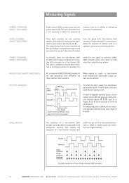
3.1. Overview of Thermal Printing Technology<br />
A brief overview of thermal printer technology might be helpful to understand how the <strong>XPM</strong><br />
200HR thermal printer family works. In most direct thermal printers, paper is fed over a<br />
soft, rotating platen and under the thermal printhead. The platen acts as a roller to advance<br />
the paper, and at the same time acts as a surface against which the spring-loaded printhead<br />
presses the paper to insure good thermal conductivity. Circuitry in the printer determines<br />
which heating elements to activate (“fire” or “burn”) to form the next row of dots on the paper.<br />
The thermal paper is coated with several compounds. At room temperature, these<br />
compounds are white in color and do not react with each other. The heat from the thermal<br />
printhead acts as a catalyst in the areas where the small printhead dots are fired, causing<br />
these compounds to react with each other and form a new compound which is a contrasting<br />
color, usually black. The platen then advances the paper to the position of the next dot row,<br />
and the process is repeated.<br />
You may note immediately several of the advantages of thermal printing. First, since the<br />
printing is done with heat, there is no noise from the printing process itself. Thermal printing<br />
is inherently quiet compared to most other technologies, such as impact dot matrix. Also,<br />
there is only one moving element in the thermal printer: the platen. This provides increased<br />
reliability and life when compared to other technologies. Since the chemistry of the thermal<br />
paper itself is what causes the printing to appear, there is no replenishment of ink ribbon, ink<br />
cartridges or toner. This makes thermal printing the least maintenance-intensive of all<br />
common printer technologies.<br />
Part No. D 690 074 Mod. No. 4 300113 LEV page 8 of 32
<strong>XPM</strong> 200HR Thermal Printer Family HENGSTLER ®<br />
3.2. Functional View<br />
Figure 1<br />
Figure 2<br />
Part No. D 690 074 Mod. No. 4 300113 LEV page 9 of 32
<strong>XPM</strong> 200HR Thermal Printer Family HENGSTLER ®<br />
Figure 3<br />
Figure 4<br />
3.3. Description of Components and Operation<br />
The key components or modules to the <strong>XPM</strong> 200HR family of thermal printers are the print<br />
mechanism, controller and optional presenter. Please refer to Figures 1, 2, 3 and 4.<br />
The thermal printhead is positioned above the platen. With the print mechanism closed, the<br />
platen acts as a roller to advance the paper at the same time as it acts as a surface against<br />
which the spring-loaded printhead presses the paper to insure good thermal conductivity.<br />
The interface, stepper motor used to turn the platen, sensors, printhead, optional presenter<br />
motors and paper cutter are all connected to the controller, which sends commands and<br />
causes these components to function at the proper time. The cutter separates the paper from<br />
the paper supply when commanded to do so by the controller. The cutter is a “pizza cutter”<br />
type which uses a disk-shaped blade that travels along the edge of a fixed cutter blade to<br />
sever the paper. Sensors monitor progress as the printed document is created. All these<br />
items are mounted to electrically-conductive mounts to discharge any static and to provide<br />
electrical noise shielding.<br />
Part No. D 690 074 Mod. No. 4 300113 LEV page 10 of 32
<strong>XPM</strong> 200HR Thermal Printer Family HENGSTLER ®<br />
Figure 5<br />
When paper (red line in figure 5) is inserted into the printer, the entrance sensor L1 detects<br />
the paper edge and starts the platen motor. The platen rotates and grasps the paper as it is<br />
manually fed. The paper advances until it reaches sensor L2, which signifies to the printer<br />
the location of the paper leading edge. The printer then reverses the paper to the<br />
programmable park position.<br />
When data is sent to the printer and printing begins, the paper is advanced by the printer<br />
platen as the individual heating elements of the thermal printhead heat as necessary to form<br />
the printout. The paper continues to advance and enters the paper cutter area, where it<br />
passes over the fixed cutting blade (lower blue element in figure 5) and out the front. Once<br />
printing is completed, the paper is advanced and a command sent to the cutter to cut off the<br />
paper. The “pizza cutter” blade (upper blue element in figure 5) cycles from one side to the<br />
other, and sensors L3 or L4 detect when the cutter has reached one of the two home<br />
positions. The paper can then be retracted to a park position to avoid wasting the paper<br />
between the printhead and cutter, ready for the next printout.<br />
When the printer runs out of paper, the printer entrance sensor L1 detects the fact and stops<br />
printing immediately to avoid possible damage to the thermal printhead from printing with no<br />
paper underneath it. How the printer reacts next depends upon the printer’s settings. One<br />
common selection is for the partial printout to be invalidated (printed over to make it illegible)<br />
as it is retracted out the back of the printer. Another is to simply eject the partial printout out<br />
the rear of the printer.<br />
If the <strong>XPM</strong> 200HR is equipped with a presenter, paper loading is as described above. When<br />
a printout is generated, it exits the printer mechanism and activates a sensor at the entrance<br />
to the presenter. The presenter motor pulls the paper in until it is pinched between a pair of<br />
roller, then stops. As the printer continues to print, a paper loop is formed in an area of the<br />
presenter between the presenter rollers and the print mechanism. (It is from this loop that the<br />
term “loop presenter” is derived.) When printing is completed, the print mechanism severs<br />
the paper from the paper supply. The presenter then advances the cut paper and presents it<br />
to the user, holding on to the last few millimeters so the printout doesn’t fall. The user can<br />
then take the printout.<br />
The presenter also includes a retract feature. With this feature, the presenter printout can be<br />
retracted back into the presenter, either by command, or if it is not taken after a certain period<br />
of time, depending upon the settings. If a retract is commanded by the controller, a flap in the<br />
presenter moves to redirect the paper downward, and the presenter feed rollers reverse. The<br />
printout is routed downward and out of the bottom of the presenter to fall into a customersupplied<br />
“reject” bin.<br />
All other user-adjustable functions and settings in the <strong>XPM</strong> 200HR are controlled by the<br />
supplied software tools.<br />
Part No. D 690 074 Mod. No. 4 300113 LEV page 11 of 32
<strong>XPM</strong> 200HR Thermal Printer Family HENGSTLER ®<br />
3.4. Location of Controls and Connectors<br />
Please see Figures 1, 3, 4 and 6 for the location of connectors, indicators and controls on the<br />
<strong>XPM</strong> 200HR series.<br />
Caution! Care must be taken to avoid injury due to the sharp cutter components<br />
when the print mechanism is open.<br />
Caution! The printhead may be hot from printing that took place shortly before<br />
opening the print mechanism and may represent a burn hazard. Care must be<br />
taken to avoid touching any hot surfaces.<br />
Pulling forward and lifting the Presenter Access Control will provide access to the presenter<br />
paper path. Press lightly on the non-moving portion of the presenter top section, to the<br />
outside of the rollers, to close the presenter again.<br />
There are several versions of the <strong>XPM</strong> 200HR controller, depending upon the features<br />
ordered. One significant difference between them is the additional connector for controlling<br />
the optional loop presenter. Figure 6 shows the <strong>XPM</strong> 200HR controller with the connectors<br />
labeled. These consist of the USB interface, the power connection, the thermal printhead<br />
connection, the paper pre-end sensor inputs (including weekend sensors), the print<br />
mechanism connections (all the sensors, switches, etc. from the print mechanism except for<br />
the thermal printhead), and the presenter connector.<br />
Figure 3 shows the rear of the print mechanism and the two paper guides.<br />
Figure 6<br />
Part No. D 690 074 Mod. No. 4 300113 LEV page 12 of 32
<strong>XPM</strong> 200HR Thermal Printer Family HENGSTLER ®<br />
3.5. Operation of Controls, Sensors and LEDs<br />
3.5.1. Printer Access Control<br />
Figure 1 shows a view of the print mechanism and identifies the Printer Access<br />
Control. By pressing the Printer Access Control downward, the upper print<br />
mechanism will be released and it can be lifted into the position shown in figure 7.<br />
Once there, it will snap into a detent position. Do not attempt to open the upper print<br />
mechanism (top cover) further than this detent position, or damage may occur to the<br />
printer. Access can now be gained to the paper path, printhead, platen and cutter as<br />
shown in figures 2 and 7 to remove paper scraps and clean paper dust.<br />
CAUTION! While the top cover is open, there is a serious risk of injury from the<br />
sharp cutter blades! Exercise care at all times to avoid injury.<br />
CAUTION! The thermal printhead heats up significantly during operation and<br />
may be hot! Avoid burns by not touching the thermal printhead directly.<br />
Avoid touching the thermal printhead at all times. Fingerprints or skin oils left<br />
on the thermal printhead may cause premature printhead failure.<br />
To close the upper print mechanism, press down on the black tab shown below<br />
Printer Access Control in figure 3 until the upper print mechanism snaps closed.<br />
Make certain that the printhead cover release lever (see figure 8) on both sides is<br />
fully engaged when closed. If not, the “printhead raised” microswitch will signal the<br />
controller that the printer is not ready and will prevent printing from taking place.<br />
Figure 7<br />
Part No. D 690 074 Mod. No. 4 300113 LEV page 13 of 32
<strong>XPM</strong> 200HR Thermal Printer Family HENGSTLER ®<br />
3.5.2. Paper Guides<br />
Figure 8<br />
Figure 3 shows the two paper guides (one left and one right) at the rear of the print<br />
mechanism. These should be adjusted to properly guide the paper into the printer.<br />
Please note that it is important at all times for the paper path to be straight. Care<br />
must be taken that the paper guides cause the paper to line up properly with the<br />
paper roll holders or the fanfold source. A crooked paper path will increase the<br />
likelihood of paper jams. The paper path should also be centered in the printer to<br />
ensure the most reliable, jam-free operation.<br />
To adjust the paper guides, simply slide them to the desired location.<br />
3.5.3. Paper Entrance / Black Mark Sensor<br />
There is a sensor in the paper entrance area of the print mechanism that serves<br />
several functions. First, it detects paper entering the print mechanism and signals the<br />
controller to activate the paper advance system. Similarly, when the printer is out of<br />
paper, this sensor detects the fact and signals the printer accordingly.<br />
The same sensor is also used to detect Black Marks. Black Marks are blackened<br />
areas placed on the paper during the converting process. They are generally used, in<br />
conjunction with appropriate printer commands, to advance the paper to a specific<br />
position after each print job. One common reason for this is to so that preprinted<br />
information is properly located with respect to information printed by the printer itself,<br />
for example, printing a date inside a preprinted box. Black marks must be located on<br />
the back (non-coated) side of the thermal paper.<br />
The <strong>XPM</strong> 200HR printer is designed to allow for numerous Paper Entrance/Black<br />
Mark sensor locations during manufacturing. (The location of this sensor cannot be<br />
changed once the printer is built.) Also, two different sensor types can be used. The<br />
most common is the reflex or reflective sensor, where the light source and detector<br />
are located on a single chip. Basically, the light strikes the white paper surface and<br />
reflects back into the sensor. If enough light reflects to activate the sensor, the printer<br />
reports that paper is present. If there is not enough light reflected, the printer<br />
assumes that this area is black, meaning the printer is on a black mark or the printer<br />
is out of paper. There are 19 different possible positions for this sensor. The<br />
possible positions of these sensors are detailed in Figure 13.<br />
The <strong>XPM</strong> 200HR can also use a through-beam sensor. This type of sensor has a<br />
separate light source and detector. The light is transmitted across the paper path into<br />
a prism, which redirects it back across the paper path into the detector. When the<br />
light is blocked and cannot reach the detector, the printer reports that paper is<br />
present. When the light does reach the sensor, the printer concludes that there is no<br />
paper present.<br />
Part No. D 690 074 Mod. No. 4 300113 LEV page 14 of 32
<strong>XPM</strong> 200HR Thermal Printer Family HENGSTLER ®<br />
The through-beam sensor can also be used in a manner similar to a Black Mark<br />
sensor. Instead of a Black Mark, a hole is used in the paper. The through-beam<br />
sensor is located in one of 19 different possible locations. The positions of these<br />
sensors are detailed in the Figure 14.<br />
3.5.4. “Printhead Raised” Sensor<br />
Two additional “Printhead Raised” microswitches are used to determine whether the<br />
printhead is in the up (do not print) or down (ready to print position). (Please note<br />
that these microswitches are wired in series, and so will only report “ready to print” if<br />
both are closed.) Normally, most of the heat generated by thermal printing is<br />
transferred to the paper being printed and is removed from the printer as the paper<br />
advances. When the printhead is up, no heat is being transferred to the paper and<br />
the heat remains in the individual dots, allowing them to overheat if activated<br />
repeatedly. Because this may cause permanent damage to the printer, the<br />
<strong>XPM</strong> 200HR firmware will prevent printing or paper loading if the head is up.<br />
The output of this microswitch pair is also available via the Query function. See the<br />
<strong>XPM</strong> 200HR Emulation Command Set Reference D 690 004 for details on<br />
determining the printhead position and the printhead temperature.<br />
3.5.5. Cutter Sensors<br />
The <strong>XPM</strong> 200HR uses a “pizza-cutter” style paper cutter. A cutting disk moves<br />
from one side to the other to sever the paper from the roll against a stationary blade.<br />
Sensors are located at the end of travel for this cutter so the controller can detect<br />
where the cutter blade is and determine in which direction it should be moved to cut<br />
the paper. Printer throughput time is improved by cutting in both directions,<br />
eliminating the need for the cutter to make a non-cutting movement to an arbitrary<br />
“home” position.<br />
3.5.6. Paper Exit Sensor<br />
A sensor on the exit side of the print mechanism detects when paper has passed<br />
through the cutter assembly and reached the paper exit.<br />
3.5.7. Paper Pre-End (Paper Low) Sensors<br />
The <strong>XPM</strong> 200HR has inputs for two pair of sensors indicating Paper Pre-End<br />
(Paper Low). (Pairs of inputs are used to allow connection, in other applications, to a<br />
dual-feed unit, which can handle two paper sources. In that case, one Paper Pre-End<br />
input is used for each paper source.) One sensor pair is used to detect standard<br />
Paper Pre-End (PPE). Connected to appropriately selected sensor, and positioned<br />
the desired distance from the end of the paper supply, it will signal via a query<br />
through the interface when paper has become low enough to activate this signal.<br />
This is normally used to allow time to change an almost empty paper roll before it is<br />
exhausted. This is an analog sensor input that is converted to a digital signal via<br />
analog to digital (A/D) conversion. Therefore, it is possible to read their analog<br />
values and use this information as a measure of sensor obstruction.<br />
The second sensor pair is also for Paper Pre-End, but is intended for use as what is<br />
commonly called a “weekend sensor” (PWE). While the standard PPE sensors<br />
detect when paper has reached some user-defined point where a paper change will<br />
be required shortly, PWE sensors are usually set to signal whether there is enough<br />
paper remaining to make it through the weekend without replenishing the paper. This<br />
is especially useful for installations where there is no staff available to change the<br />
paper over the weekends. The PWE input is a direct digital input. Since no supply is<br />
provided to power an LED-style sensor, these inputs are best used with a<br />
microswitch.<br />
Part No. D 690 074 Mod. No. 4 300113 LEV page 15 of 32
<strong>XPM</strong> 200HR Thermal Printer Family HENGSTLER ®<br />
Figure 9 shows the input circuit for these sensor connectors. The characters in<br />
parenthesis show the input as it is labeled in the <strong>XPM</strong> 200HR Diagnostic Tool.<br />
There is also an auxiliary input available on this connector. The wiring is the same as<br />
the PPE inputs. The status of this input is reported by the printer when queried.<br />
Please note that the Auxiliary input may not be available if the printer is equipped with<br />
a presenter. The pinout of the Paper Pre-End Sensors connector is as follows.<br />
PPE Sensors Connector<br />
Pin 6 – 5 VDC (to be used as a voltage source for pull-ups, etc. for PWE, AUX<br />
sensors)<br />
Pin 7 – Common (Ground)<br />
Pin 8 – PPE Sensor Signal 1 (A1)<br />
Pin 9 – PPE Sensor Power Output 1 (A1)<br />
Pin 10 – PPE Sensor Power Output 2 (A2)<br />
Pin 11 – PPE Sensor Signal 2 (A2)<br />
Pin 12 – Auxiliary (AUX) Input<br />
Pin 19 – PWE Sensor Signal 1 (B1)<br />
Pin 20 – PWE Sensor Signal 2 (B2)<br />
Figure 9<br />
Please note that the <strong>XPM</strong> 200HR does nothing more with the PPE, PWE and AUX<br />
signals than report their status through the interface. For this reason, these inputs<br />
are not limited to being used for PPE or PWE. Any one of them may be used to<br />
detect the status of a door, for example, or any other status that can be sensed via a<br />
microswitch or (in the case of the PPE inputs) an appropriate optical sensor.<br />
Part No. D 690 074 Mod. No. 4 300113 LEV page 16 of 32
<strong>XPM</strong> 200HR Thermal Printer Family HENGSTLER ®<br />
3.5.8. LED Indicators<br />
There are two LED indicators in the <strong>XPM</strong> 200HR series printers, located on the<br />
opposite side of the controller board near the USB connector. These LEDs are used<br />
to signal some status information concerning the <strong>XPM</strong> 200HR printer. The<br />
following is a partial listing of the information supplied.<br />
There are several flashing speeds used in the <strong>XPM</strong> 200HR printer LEDs. These<br />
are:<br />
Slow: 0.5 Hertz (LED is “on” for one second and “off” for one second)<br />
Medium: 1 Hz (“on” for .5 seconds and “off” for .5 seconds)<br />
Flicker: 10 Hz (“on” for 50 ms and “off” for 50 ms)<br />
Off<br />
On<br />
Red LED Green LED Meaning<br />
Printer operational, paper<br />
available, not printing<br />
Printer operational, paper<br />
available, printing<br />
Printer operational, out of paper<br />
Exchanging data (firmware, fonts,<br />
logos, etc; writing to flash<br />
Printer not operational due to<br />
printhead open, wrong<br />
configuration , wrong voltage or<br />
hard reset<br />
Print mechanism jammed<br />
Cutter jammed<br />
Feed unit jammed<br />
Presenter jammed<br />
Fatal error; SDRAM defective<br />
Fatal error; Board type cannot be<br />
identified<br />
Probable system stall during<br />
initialization phase<br />
Probable system stall during boot<br />
phase<br />
Please note that much more detailed information concerning the printer’s current<br />
state can be obtained by requesting the printer’s status via the interface. Please refer<br />
to the <strong>XPM</strong> 200HR Emulation Command Set Reference D 690 004 for details.<br />
3.6. Graphic Printing vs. Printing with Printer’s Fonts<br />
One area that causes frequent confusion with regard to printers in general is that of graphic<br />
printing versus printing using the printer’s internal fonts. An explanation here may help clarify<br />
this and make application of the <strong>XPM</strong> 200HR easier for you.<br />
All printers contain a set of commands that will cause the printer to perform different<br />
functions. (For the <strong>XPM</strong> 200HR family of thermal printers, these commands are<br />
documented in the <strong>XPM</strong> 200HR Emulation Command Set Reference, P/N D 690 004.) The<br />
functions are very diverse and there are no standards for what these functions may be. This<br />
allows printer manufacturers to innovate and build unique features into their products. These<br />
commands are often referred to as the printer’s “Native Commands”.<br />
A printer’s Native Commands are of many different types, but a few are of particular interest<br />
to us here. One is the family of commands for printing graphics. It is these commands that<br />
allow pictures and other graphic images of any type to be printed.<br />
Part No. D 690 074 Mod. No. 4 300113 LEV page 17 of 32
<strong>XPM</strong> 200HR Thermal Printer Family HENGSTLER ®<br />
Another family of commands of interest to us here is the text commands. These commands<br />
involve printing text in response to ASCII data sent to the printer. The printer itself contains<br />
one or more character sets. In these character sets, one printable character corresponds to<br />
one ASCII character. There are also commands for positioning and modifying the printout<br />
from these character sets, such as tab and indent commands and commands to enlarge the<br />
internal character set by some factor.<br />
When printing from the internal character sets (we’ll call that “ASCII printing” here for<br />
convenience), characters are sent to the printer and the corresponding characters from the<br />
character set are printed. This has both advantages and disadvantages. The biggest<br />
advantage is that the host need only send one character per printed character. So if 40<br />
characters are being printed on a line, for example, only 40 bytes of data (plus any overhead<br />
for formatting, indenting, etc.) need be transmitted over the interface. In other words, you can<br />
print a lot of text and need send only a little data. The downside is a lack of flexibility. In<br />
today’s Windows ® world, we are all used to printing exactly what we see on our computer<br />
screens, in the same font, size, etc. as we see it. But with ASCII printing, what will be printed<br />
will be based on the printer’s internal character set.<br />
The other type of printing we’ll call “Graphic printing”. This is what happens when you print to<br />
an ink jet or laser printer from your PC. The information displayed on the screen is sent to a<br />
print driver. This print driver, which is unique for each printer, translates what is on the screen<br />
as a graphic into graphic Native Commands to be sent to the printer. Everything printed<br />
through a print driver prints as graphics. It takes a lot more data to transmit graphics than<br />
to transmit ASCII. In our 40 character example, assuming a 12 x 20 pixel character, the<br />
<strong>Hengstler</strong> <strong>XPM</strong> 200HR printer would require 1,600 bytes to print one line. (Please note that<br />
these are estimates, and that various compression routines also impact the print speed.)<br />
The advantage of Graphic printing, then, is the ability to print anything; pictures, text, photos,<br />
etc. exactly as you see it on your screen. The disadvantage is that to do so, much more data<br />
(40 times as much data in our example) must be sent over the interface.<br />
As a practical matter, then, it comes down to this. If you are doing ASCII printing, you can<br />
use USB or a serial interface. Both are fast enough to handle the smaller amount of data<br />
being sent. But if you are doing Graphic printing, USB is a far better choice due to its higher<br />
speed, and serial may increase the time to complete a printout to an unacceptably long<br />
period.<br />
4. Unpacking<br />
Care should be taken when unpacking your <strong>XPM</strong> 200HR printer to preserve the packing<br />
material for possible future use. <strong>XPM</strong> 200HR packing is specifically designed to protect the<br />
printer from damage in the harsh environment of trucks and aircraft. Please be sure to use<br />
this packing if it ever becomes necessary to reship your <strong>XPM</strong> 200HR unit.<br />
5. Major Options<br />
5.1. Presenter<br />
<strong>XPM</strong> 200HR printers can be supplied with an presenter. There are generally three reasons<br />
to use a presenter. One is to prevent vandalism of the printer paper; a presenter prevent a<br />
user from touching their printout until after it has been severed from the paper roll, eliminating<br />
the opportunity for vandals to try to pull all the paper from the roll through the printer. The<br />
second reason is to protect confidential information. If confidential information is included in a<br />
printout that is presented, but the printout is not taken, the presenter can be configured to<br />
automatically retract the printout and store it in an internal reject bin. The third reason is to<br />
keep the floor around the device or kiosk in which the printer is mounted clean. If several<br />
users didn’t take their receipts, they might well end up in a big pile on the floor, representing a<br />
slip hazard. By using the presenter with retract, untaken receipts will be safely stored in the<br />
reject bin.<br />
Part No. D 690 074 Mod. No. 4 300113 LEV page 18 of 32
<strong>XPM</strong> 200HR Thermal Printer Family HENGSTLER ®<br />
6. Installation<br />
6.1. Function<br />
Please note that the <strong>XPM</strong> 200HR printer is a module designed to be integrated into a<br />
system and to be operated only as a part of that system, for example, in a kiosk. All technical<br />
specifications and instructions contained in this manual and related documentation must be<br />
considered and complied with in order to achieve successful operation in the completed<br />
system.<br />
6.2. Mounting Printer<br />
The <strong>XPM</strong> 200HR printer is designed to be mounted horizontally, (with the paper exit parallel<br />
to the floor), and separately from its controller. See figure 10 and drawing D690075 for<br />
detailed dimensions, mounting screw sizes, etc. If no presenter is being used, the printer may<br />
be angled downward by 90°. It may also be angled upward, as long as the design of the<br />
system into which it mounts is such that a printout cannot slide back into the printer after it is<br />
cut.<br />
<br />
<br />
Please note that the printer itself mounts via two M4 anchor nuts built into the print<br />
mechanism. An M3 screw with lock washer (not supplied) are used for mounting.<br />
Note: It is critical that the length of the mounting screw conform to the “thread length”<br />
dimensions shown in the drawing below. (Specifically, a minimum of 7.4 mm and a maximum<br />
of 8.5 mm above the mounting surface.) A longer screw may damage the printer, while a<br />
shorter one may not grip it properly.<br />
If a presenter is used, the printer must be mounted parallel to the floor with the paper exiting<br />
to parallel to the floor. An angled orientation will interfere with the loop presenter function.<br />
Care must be taken during installation to ensure that cables are not pinched or cut at any<br />
time, including when any doors or hatches are closed or moving parts of the device moved.<br />
Figure 10<br />
Part No. D 690 074 Mod. No. 4 300113 LEV page 19 of 32
<strong>XPM</strong> 200HR Thermal Printer Family HENGSTLER ®<br />
<br />
<br />
<br />
<br />
<br />
<br />
<br />
<br />
<br />
<br />
6.3. Mounting Controller<br />
Proper ESD protection should be used at all times when handling and/or connecting the<br />
controller.<br />
Static electricity can damage sensitive electronic components. Discharge your body's static<br />
electric charge by touching a grounded surface before performing any hardware procedure.<br />
Never remove the controller circuit board from its antistatic bag until you are ready to install it<br />
to prevent electrostatic damage.<br />
The <strong>XPM</strong> 200HR controller board must be correctly grounded using the main ground, as<br />
described below.<br />
The driver components of the <strong>XPM</strong> 200HR controller board, as well as thermal printhead and<br />
the motors, can become hot during operation, causing a risk of burn injuries. Care should be<br />
taken to ensure adequate cooling ventilation to the system, and to avoid contact with these<br />
components!<br />
Connection or disconnection of power cables, and/or of the components, should only<br />
performed while power is off to avoid damaging or destroying electrical components.<br />
Use only a power supply with the specified capacity. Incorrect voltage can damage <strong>XPM</strong><br />
200HR controller circuitry as well as the thermal printhead of the <strong>XPM</strong> 200HR print<br />
mechanism.<br />
Penetrating liquids, dust or paper scraps may cause faults or short circuits.<br />
The <strong>XPM</strong> 200HR controller, as well as the complete system, should not be installed near high<br />
frequency devices or strong magnetic fields.<br />
The <strong>XPM</strong> 200HR controller, as well as the complete system, contains sensitive mechanical<br />
and electronic components which could be damaged or destroyed by extreme vibration or<br />
shock, such as that caused by impact or dropping.<br />
The <strong>XPM</strong> 200HR Controller board must be attached to a grounded base which is made of<br />
sheet steel. Use screws and nylon standoffs to mount the Controller board to this base. It is<br />
recommended that flat washers and internal tooth lock washers be used to secure the<br />
controller.<br />
Ensure that the main ground is correctly connected to the sheet metal base!<br />
Be sure to maintain the required open space above and below the controller board for<br />
cooling, as follows:<br />
Min. space below = 5 mm<br />
Min. space above = 26 mm<br />
1. After mounting the <strong>XPM</strong> 200HR controller board, install the power and interface<br />
cables to the <strong>XPM</strong> 200HR printer mechanism and other optional devices, but do not<br />
connect the USB interface cable to the printer. Check the correct positioning of all<br />
connectors; please refer to the layout shown in figure 6.<br />
2. Switch Power ON and insert paper into the <strong>XPM</strong> 200HR. An info printout should<br />
automatically be generated.<br />
3. Leave power on and install the USB interface cable to your host system.<br />
4. Install the necessary <strong>XPM</strong> 200HR printer driver software as a local printer.<br />
Mount the controller as shown in Figure 10A. Take care that the controller is mounted as<br />
close as possible to the print mechanism, within reach of the cable assemblies. Check that<br />
the controller is not subject to damage when paper is loaded, doors are opened, etc.<br />
Part No. D 690 074 Mod. No. 4 300113 LEV page 20 of 32
<strong>XPM</strong> 200HR Thermal Printer Family HENGSTLER ®<br />
Consideration should be given to EMI/EMC; a sheet metal cover may provide both<br />
mechanical protection for the controller and additional EMI/EMC shielding.<br />
6.4. Wiring<br />
6.4.1. Power<br />
Figure 10A<br />
Power is connected to the <strong>XPM</strong> 200HR thermal printer via a JST connector. The<br />
connector consists of a JST VHR-4N shell and two SVH-21T-P1.1 contacts. Wiring is<br />
as follows:<br />
Pin Function<br />
1 Ground (0 VDC)<br />
2 Ground (0 VDC)<br />
3 +24 VDC<br />
4 +24 VDC<br />
Part No. D 690 074 Mod. No. 4 300113 LEV page 21 of 32
<strong>XPM</strong> 200HR Thermal Printer Family HENGSTLER ®<br />
6.4.2. Interfacing<br />
USB<br />
The USB versions of the <strong>XPM</strong> 200HR printer employ a standard USB interface<br />
cable (5 pin Mini-B connector on the printer end) to communicate from the host to the<br />
printer. Be sure that the Mini-B connector is fully engaged with the mating connector<br />
on the printer. The other end of the cable plugs into the USB port on the host. The<br />
cable length must be limited to under 3 meters.<br />
Once the printer is connected with the host and the driver is installed, be sure to set<br />
the Port in the driver to the appropriate USB port to match the physical host-side<br />
interface cable port.<br />
USB Pinout<br />
Pin<br />
Number Signal name I/O Function<br />
1 NC no connection<br />
2 D- I/O Data -<br />
3 D+ I/O Data +<br />
4 NC no connection<br />
5 SGND I/O Signal Ground<br />
6.5. Paper Supply<br />
6.5.1. Paper Roll Holder<br />
Based on our extensive experience in designing printers, we would urge you to<br />
consider the following topics and implement your paper roll holder design with care.<br />
Large Diameter Rolls: When using paper rolls over 100 mm in diameter, a spring<br />
buffer, or “dancer bar”, should be considered. This usually takes the form of a springloaded<br />
arm under which the paper is placed before feeding it into the printer. As the<br />
printer starts to print, slack is taken up from the paper roll. This starts to lift the arm<br />
against the spring, which puts force on the paper roll and starts it moving slowly. As<br />
more printing takes place the roll gradually accelerates until it’s up to printing speed.<br />
Without the dancer bar, slack paper would be taken up until it was suddenly no longer<br />
slack. Now the printer must accelerate a large, heavy paper roll from zero speed to<br />
full print speed in essentially no time. This can cause the paper advance motor to<br />
stall or the paper to slip against the platen, causing shortened characters until the<br />
paper roll is up to speed.<br />
Spindle Friction: Another important consideration is spindle friction. As a paper roll<br />
rotates, it slides against the spindle that holds it, assuming a fixed spindle. This<br />
friction will tend to impede the paper roll’s free motion, and is dependent upon the<br />
weight of the roll, the smoothness and material of the spindle, and the smoothness<br />
and material of the paper core. When possible, especially with paper rolls over 100<br />
mm in diameter, design the spindle so that it can rotate, greatly decreasing friction<br />
and drag.<br />
Catch Points: More paper jams and transport problems are caused by catch points<br />
than any other issue. Make sure that the paper path is free of anything that can<br />
interfere with free paper flow, especially any sharp edges or “pinch points” into which<br />
the paper may stray and become caught.<br />
Alignment: Any paper roll holder design must hold the paper square to the printer in<br />
all planes. If the paper is angled in any way, it will enter the printer at an angle and<br />
will be more likely to cause paper jams.<br />
Part No. D 690 074 Mod. No. 4 300113 LEV page 22 of 32
<strong>XPM</strong> 200HR Thermal Printer Family HENGSTLER ®<br />
Rigidity: It is important that the paper roll holder support the paper firmly and not<br />
move. This is especially true in high-speed printing applications and in large diameter<br />
paper roll applications. Many paper roll holders are made from metal too thin to<br />
support the heavy paper rolls they are expected to handle. This results in twisting<br />
and warpage while printing, which binds the paper and causes paper jams. Vibration<br />
during printing may also cause undesired movement of the paper roll.<br />
Shipment: Do not ship your product with a paper roll mounted in the paper roll<br />
holder. The heavy weight of the paper roll can easily bend or otherwise damage the<br />
paper roll holder, as witnessed numerous times.<br />
6.6. Power Supply Specifications<br />
Selection of a power supply for thermal printers depends upon the printer’s application, what<br />
percentage of the printout is black, frequency with which printouts are generated, and more.<br />
In particular, thermal printers draw very high currents for very short time periods (usually<br />
under one millisecond). The most important issue is not peak current, but the length of time<br />
that the power supply is able to deliver instantaneous current over its rated maximum, and for<br />
how long the print job prints high black percentages, thereby drawing high current. It is<br />
important that the power supply’s over-current system does not shut down the power supply<br />
when these brief, high current surges occur.<br />
With that said, we recommend the following power supply specifications for most applications.<br />
Please see the “Technical Specifications” section near the end of this document for full<br />
details.<br />
DC Output Voltage: 24 volts ± 5%<br />
DC Output Current (nominal): 5.5 to 8.0 amperes<br />
Hold Up Time: 20 ms minimum<br />
Current Limitations: 16 amperes minimum current limit<br />
7. Operation<br />
7.1. Loading Paper<br />
Before loading the printer, make sure that the printhead is in the “closed” position; see figure<br />
4 for details.<br />
Insert the paper, thermosensitive side up, between the paper guides. You will hear the platen<br />
motor start to run as soon as the paper detection sensor is reached. Continue to feed the<br />
paper until the printer platen grasps it and pulls it forward into the printer.<br />
The <strong>XPM</strong> 200HR thermal printer family is designed to use paper with the thermosensitive<br />
side on the outside of the paper roll. This is important as the printer is optimized to deal with<br />
paper curl angling the paper end downward.<br />
Please note that the <strong>XPM</strong> 200HR thermal printer family will, unless specifically configured<br />
not to do so, print an Information Report immediately when paper is loaded. This short report<br />
is extremely helpful during setup and configuration of the <strong>XPM</strong> 200HR printer. This report<br />
contains detailed information concerning the printer itself and its features, the firmware<br />
installed, the status of information in the flash memory, status of the A/D converter outputs,<br />
and the many settings that configure the printer itself. For example, this report will show all<br />
the current serial communication settings.<br />
Please note that many of the software tools supplied with the <strong>XPM</strong> 200HR driver also allow<br />
this report to be printed by simply clicking on the “Print Info” button.<br />
Part No. D 690 074 Mod. No. 4 300113 LEV page 23 of 32
<strong>XPM</strong> 200HR Thermal Printer Family HENGSTLER ®<br />
7.2. Print Speed<br />
Print speed is affected by many factors. Significant factors affecting print speed include:<br />
• Type of interface (USB fastest)<br />
• ASCII printing vs. Graphics printing (ASCII fastest)<br />
• Data transmission rate (serial) (faster is better)<br />
• Default print density settings (smaller impact, but lower density is faster)<br />
• Dot history factor (smaller impact, but “off” is faster)<br />
• Dot history levels (smaller impact, but “off” is faster)<br />
• Burn time correction setting (smaller impact, but the most negative numbers are faster)<br />
• Multi-strobe factor (“off” is faster)<br />
• Available current (higher is faster)<br />
• Default print speed setting in configuration (higher is faster)<br />
7.3. Cutter Operation<br />
The <strong>XPM</strong> 200HR uses a “pizza-cutter” style paper cutter. A cutting disk moves from one<br />
side to the other to sever the paper from the roll against a stationary, fixed blade. A separate<br />
motor is used to control a helical cam that moves the “sled” holding the cutting disk. See<br />
Figure 2.<br />
The cutter components can be accessed by opening the print mechanism. See “Printer<br />
Access Control” above for cautions, details and instructions.<br />
The <strong>XPM</strong> 200HR configuration tool allows the specification of the weight of the paper being<br />
printed. This information is used by the printer to determine how fast the cutter should move<br />
while cutting the paper. With thinner paper, cutting can be faster. Thicker paper requires<br />
greater cutting torque from the cutter motor, which is achieved by cutting more slowly. This is<br />
automatic and transparent to the application.<br />
In the event of a paper jam, the <strong>XPM</strong> 200HR can be configured to make several repeat<br />
attempts to cut the paper. The number of attempts can be specified by using the <strong>XPM</strong><br />
200HR Configuration Tool. If these attempts are unsuccessful, the printer will report a<br />
paper jam through the status system.<br />
Note: Please be sure to remove power from the printer before opening the print mechanism<br />
and accessing the cutter blades! Always keep your fingers clear of the sharp blades<br />
themselves!<br />
7.4. Print Density<br />
The darkness of the printout can be adjusted to match the paper and your application by<br />
using the appropriate printer command (see <strong>XPM</strong> 200HR Command Set Manual P/N D 690<br />
005) or by use of the “Print Density” settings in the Windows XP/7 driver. Increasing print<br />
density increases the “burn time”, (the length of time that the thermal printhead elements are<br />
heated) and may decrease print speed.<br />
<br />
Note: Excessively long burn times may adversely affect printer life!<br />
7.5. Invalidation<br />
The <strong>XPM</strong> 200HR printer includes the ability to invalidate printouts (render them unreadable<br />
by overprinting them with a random pattern) under certain conditions. These conditions<br />
include after loading paper; at the end of paper; when data has been lost; and on initialization.<br />
In all cases, the purpose of the feature is to prevent printouts that might be partially valid from<br />
being misused. For example, if a ticket had been in the process of printing and the power<br />
failed, the printer would stop printing. Upon restoration of power, it would be preferable to<br />
invalidate the partially printed ticket and, if appropriate, have the host send a new one to be<br />
printed. By enabling “Invalidate paper on initialization”, this can be accomplished.<br />
Part No. D 690 074 Mod. No. 4 300113 LEV page 24 of 32
<strong>XPM</strong> 200HR Thermal Printer Family HENGSTLER ®<br />
7.6. <strong>XPM</strong> 200HR Digital Tools<br />
The <strong>XPM</strong> 200HR family of thermal printers includes with the Windows XP/7 driver a series<br />
of very useful tools. These can be run directly from the Tools folder of the driver package<br />
once the driver has been installed. A brief summary of these tools is shown below.<br />
<br />
Note: It is important to note that the behavior of the <strong>XPM</strong> 200HR is heavily<br />
dependent upon the settings determined by the Configuration Tool.<br />
<strong>XPM</strong> 200HR Command Tool: Tool for sending Native Commands to the printer. Very<br />
useful while developing code for your application.<br />
<strong>XPM</strong> 200HR Configuration Tool: A very important tool that allows you to change virtually<br />
any variable setting or performance characteristic of your <strong>XPM</strong> 200HR printer.<br />
<strong>XPM</strong> 200HR Diagnostic Tool: A powerful tool for identifying possible issues with your<br />
printer, its peripherals and firmware by examining the details of its operation.<br />
<strong>XPM</strong> 200HR Font Tool: Used for uploading and assigning different fonts within the <strong>XPM</strong><br />
200HR printer.<br />
<strong>XPM</strong> 200HR Image Tool: This very helpful tool creates <strong>XPM</strong> 200HR format graphic files<br />
from standard format graphic files so they can be uploaded as stored images.<br />
<strong>XPM</strong> 200HR Print Terminal: The Print Terminal has six sets of 24 buttons each, many of<br />
them preprogrammed to transmit commands to your <strong>XPM</strong> 200HR printer. All buttons are<br />
programmable to make them transmit whatever is needed. This tool is very popular with<br />
software developers who are integrating the <strong>XPM</strong> 200HR into their products as a tool that<br />
they use to verify command sequences and responses.<br />
<strong>XPM</strong> 200HR Uninstaller Tool: Use this tool to uninstall single or all versions of the <strong>XPM</strong><br />
200HR driver.<br />
<strong>XPM</strong> 200HR Upload Tool: Used to upload new firmware, specific data files, etc. to the<br />
flash area of your <strong>XPM</strong> 200HR printer.<br />
<strong>XPM</strong> 200HR Wide Font Tool: Used for uploading Wide Font formats (such as Chinese or<br />
Korean) from standard graphic files.<br />
8. Low Current Operation<br />
There are numerous factors that affect thermal printer current. It is possible to manipulate these<br />
factors consciously to reduce current draw for situations where this is important, such as operating<br />
from batteries. If battery operation only occurs when power has failed, the host software can be<br />
programmed to print at a faster, higher current rate during normal operation and then switch the<br />
<strong>XPM</strong> 200HR to a lower current mode when the system switches to battery operation. The following<br />
are some considerations to aid in reducing current draw.<br />
8.1. Print Speed<br />
With thermal printers, average current is proportional to print speed. Since the burn time for<br />
each dot row is fixed, when printing slower there is more pause between burns and therefore<br />
a lower average current. (The peak current is determined by the number of dots burned at<br />
once, and so is unaffected by print speed.) The <strong>XPM</strong> 200HR target print speed (called the<br />
“target speed” because other settings may cause the actual print speed to be lower than this)<br />
can be set via the interface; please refer to the <strong>XPM</strong> 200HR Emulation Command Set<br />
Reference for the specific command sequence. The slower this print speed is, the lower the<br />
average current draw will be. Note that when using the <strong>XPM</strong> 200HR Windows XP/7 driver,<br />
the driver will override settings sent to the printer directly via the interface.<br />
Part No. D 690 074 Mod. No. 4 300113 LEV page 25 of 32
<strong>XPM</strong> 200HR Thermal Printer Family HENGSTLER ®<br />
8.2. Graphics/Bar Codes<br />
Printing graphics rather than text consumes more current than printing only text. Typical textonly<br />
printing is considered to be 12.5% coverage on average, while graphic printing varies<br />
from 25% to 50% average, consuming 2X to 4X the average current. Printing bar codes is in<br />
the same category, and draws about 4X the current of text. Both should be avoided or<br />
minimized to reduce current draw. In terms of current draw, it does not matter whether<br />
printing is done using the printer’s internal character set or the via the driver.<br />
8.3. Reverse Printing<br />
Reverse printing should be avoided, since everything that’s normally black becomes white,<br />
and vice-versa, drawing (in average text) about 8 times the current.<br />
8.4. Dot History Factor<br />
Dot history monitors previously burned dots and reheats them for a shorter time to prevent<br />
blooming and excessively black areas, thereby decreasing total current consumption. Using<br />
dot history and minimizing the main burn time will reduce average current draw. Please refer<br />
to the <strong>XPM</strong> 200HR Emulation Command Set Reference for the specific command<br />
sequence.<br />
8.5. Burn Time Correction<br />
The <strong>XPM</strong> 200HR family of printers include a feature that will adjust burn time automatically<br />
depending upon ambient temperature. Burn Time Correction allows the adjustment of these<br />
burn times to “tune” the printer to maximum performance for any given paper, thereby<br />
improving print quality but having little effect on current consumption. If current draw is truly<br />
critical, reducing these values will reduce current slightly at the cost of lower contrast in the<br />
printout. Please refer to the <strong>XPM</strong> 200HR Emulation Command Set Reference for the<br />
specific command sequence.<br />
8.6. Multi-Strobe Factor<br />
This feature is the only <strong>XPM</strong> 200HR software feature that will reduce peak current. When<br />
this features is turned on, only one side of the printhead is fired at a time, reducing the peak<br />
current by a factor of two, but having virtually no effect on average current. This is very useful<br />
if your power supply has a restrictive maximum current, but slows printing. Please refer to the<br />
<strong>XPM</strong> 200HR Emulation Command Set Reference for the specific command sequence.<br />
8.7. Print Density Adjustment<br />
Increasing print density will improve print quality, but at the same time will increase average<br />
current. Therefore Print Density is always a trade-off between these two characteristics. Use<br />
the lowest print density that is visually acceptable to minimize current draw. Please refer to<br />
the <strong>XPM</strong> 200HR Emulation Command Set Reference for the specific command sequence.<br />
Part No. D 690 074 Mod. No. 4 300113 LEV page 26 of 32
<strong>XPM</strong> 200HR Thermal Printer Family HENGSTLER ®<br />
9. Troubleshooting<br />
Symptom Possible Cause Corrective Action<br />
No LEDs light on printer 1. Power not connected<br />
2. PCB mounted fuse blown<br />
1. Check line cord and outlet<br />
2. Return printer for fuse<br />
replacement; not field<br />
replaceable<br />
LEDs flashing See Section “LED Indicators” See Section “LED Indicators”<br />
Printer prints blank paper 1. Paper inserted upside-down<br />
2. Wrong side of roll coated<br />
Print quality poor<br />
Baud rate, other configuration<br />
setting changes not<br />
implemented after use of<br />
Configuration Tool<br />
3. Printout positioned outside<br />
printable area by “set”<br />
command<br />
1. Print density set too low<br />
2. Printhead not fully lowered<br />
3. Incorrect paper type for<br />
<strong>XPM</strong> 200HR printhead<br />
1. Printer was not reset after<br />
changes made with<br />
Configuration Tool.<br />
10. Maintenance<br />
The <strong>XPM</strong> 200HR printers require very little maintenance.<br />
<br />
<br />
1. Invert paper roll<br />
2. Invert roll as test, have<br />
paper made properly<br />
3. Change “set” command<br />
settings to relocate printout<br />
1. Adjust print density, other<br />
burn time adjustments.<br />
2. Lower printhead.<br />
3. Procure and use correct<br />
paper.<br />
1. Reset printer. Consider<br />
enabling “Automatically<br />
reset printer” option on<br />
“Tool Settings” tab of <strong>XPM</strong><br />
200HR Configuration<br />
Tool.<br />
Note: Discharge your body’s static electric charge by touching a grounded surface before<br />
performing any maintenance procedure. Do not touch the connector pins of the printhead<br />
cable with your bare hands.<br />
Note: Do not touch the surface of the thermal printhead. Mechanical stress or shock<br />
(including foreign contamination) to the surface of the printhead substrate should be avoided<br />
to prevent printhead damage.<br />
Clean the <strong>XPM</strong> 200HR whenever it becomes dusty, as paper dust will reduce the friction of the<br />
platen and cause the print quality to deteriorate.<br />
<br />
• Open the print mechanism by using the Printer Access Control. Remove any paper, if<br />
necessary.<br />
• Clean the platen with a special platen cleaning agent and a lint-free cloth. DO NOT use<br />
alcohol to clean the platen because alcohol hardens the platen material.<br />
• Gently wipe the surface of the thermal printhead using a cotton pad soaked in<br />
METHANOL to remove dust on the heating elements. DO NOT use sandpaper or other<br />
abrasives.<br />
• Dry the <strong>XPM</strong> 200HR mechanism completely and reload the paper.<br />
Note: Condensation should be avoided. If condensation occurs, do not power the printer until<br />
all condensation has dissipated.<br />
Part No. D 690 074 Mod. No. 4 300113 LEV page 27 of 32
<strong>XPM</strong> 200HR Thermal Printer Family HENGSTLER ®<br />
11. Repair<br />
All <strong>Hengstler</strong> printers are repaired at our facility in Aldingen, Germany. For details, and to arrange for<br />
the return of a printer for repair, please contact us at:<br />
12. Buying Paper<br />
HENGSTLER <strong>GmbH</strong><br />
Uhlandstrasse 49<br />
78554 Aldingen / Germany<br />
Tel. +49 (0) 7424-89 0<br />
Fax +49 (0) 7424-89 500<br />
eMail: info@hengstler.com<br />
www.hengstler.com<br />
12.1. Sourcing Paper<br />
In order to maintain your warranty, use only paper that conforms with <strong>XPM</strong> 200HR Paper<br />
Specification D 689 xxx. Use of paper that does not conform with this specification may<br />
adversely affect the performance of your <strong>XPM</strong> 200HR printer and/or damage your printer.<br />
Please note that the <strong>XPM</strong> 200HR can use either roll or fanfold paper. When using fanfold<br />
paper, care must be taken to configure the printer, black mark, and positioning so that the cut<br />
always occurs after the fanfold bend, not on it or before it. Failure to do so will cause cutting<br />
problems and will likely increase paper jams.<br />
12.2. Converting Paper<br />
Thermal paper is usually purchased through paper converters. These companies buy large,<br />
jumbo rolls of specific paper types from the few true paper manufacturers in the world and<br />
then cut it and roll it to your specifications. You may elect to have preprinting or black marks<br />
added at this time, as well. Please make sure that any paper a converter wishes to supply<br />
you for use with your <strong>XPM</strong> 200HR printer conforms with <strong>XPM</strong> 200HR Paper Specification<br />
D 689 112.<br />
12.3. Black Mark Sensor Location<br />
The Black Mark sensor (which also functions as a “paper present” sensor) on the <strong>XPM</strong><br />
200HR printers can be located in numerous positions during manufacturing. Figure 13<br />
shows where the black marks should be located in order to be detected when a reflex sensor<br />
is used. The default (standard) sensor positions are so marked.<br />
The <strong>XPM</strong> 200HR printer is designed to allow for numerous Paper Entrance/Black Mark<br />
sensor locations during manufacturing. (The location of this sensor cannot be changed once<br />
the printer is built.) Also, two different sensor types can be used. One is the reflex or<br />
reflective sensor, where the light source and detector are located on a single chip. Basically,<br />
the light strikes the white paper surface and reflects back into the sensor. If enough light<br />
reflects to activate the sensor, the printer reports that paper is present. If there is not enough<br />
light reflected, the printer assumes that this area is black, meaning the printer is on a black<br />
mark or the printer is out of paper. Black marks must be located on the back (non-coated)<br />
side of the thermal paper. There are 19 different possible positions for this sensor. The<br />
positions of these sensors are detailed in Figure 13. (Please note that sensor positions 1, 7<br />
and 16 are not usable due to a lack of an open position to their left.) The default (standard)<br />
positions are so marked. Paper suppression guides are small inserts with mushroom-shaped<br />
heads that are used to ensure that the paper is at the correct distance to be detected properly<br />
by the sensor. Please also note that sensor locations other than the default location are<br />
intended for OEM applications.<br />
Part No. D 690 074 Mod. No. 4 300113 LEV page 28 of 32
<strong>XPM</strong> 200HR Thermal Printer Family HENGSTLER ®<br />
Figure 13<br />
The <strong>XPM</strong> 200HR can also use a through-beam sensor. This type of sensor has a separate<br />
light source and detector. The light is transmitted across the paper path into a prism, which<br />
redirects it back across the paper path into the detector. When the light is blocked and<br />
cannot reach the detector, the printer reports that paper is present. When the light does<br />
reach the sensor, the printer concludes that there is no paper present.<br />
The through-beam sensor can also be used in a manner similar to a Black Mark sensor.<br />
Instead of a Black Mark, a hole is used in the paper. The through-beam sensor is located in<br />
one of 19 different possible locations; the centerline location of the paper path is the default.<br />
The possible positions of these sensors are detailed in the Figure 14.<br />
Part No. D 690 074 Mod. No. 4 300113 LEV page 29 of 32
<strong>XPM</strong> 200HR Thermal Printer Family HENGSTLER ®<br />
Figure 14<br />
Part No. D 690 074 Mod. No. 4 300113 LEV page 30 of 32
<strong>XPM</strong> 200HR Thermal Printer Family HENGSTLER ®<br />
13. Technical Specifications<br />
Technology:<br />
Direct Thermal<br />
Print Speed:<br />
Up to 100 mm/sec<br />
Resolution:<br />
300 dpi<br />
Printhead Life<br />
Abrasion (based<br />
on 12.5% print density)<br />
Electrical:<br />
Graphic Driver:<br />
Bar Codes:<br />
Internally Generated:<br />
Externally Generated:<br />
Paper Width:<br />
Printable Width:<br />
Paper Weight:<br />
Paper Capacity:<br />
100 km of paper<br />
100 million dot pulses<br />
Windows ® XP/7, Linux (CUPS)<br />
UPC-A, UPC-E, EAN-13, EAN-8,<br />
Code 39, Interleaved 2 of 5,<br />
Code 128, Codabar, PDF 417<br />
Any, generated by<br />
Windows ® standard GDI file<br />
by host<br />
210-220 mm (narrower widths may be possible in certain OEM<br />
applications. Contact <strong>Hengstler</strong> for details.)<br />
216 mm<br />
80-100 g/m² (Other paper weights may be possible in certain<br />
OEM applications. Contact <strong>Hengstler</strong> for details.)<br />
6 inch (150 mm) roll diameter<br />
12 inch (300 mm) (reduced performance)<br />
Interface Type: USB 1.1<br />
(Cable length
<strong>XPM</strong> 200HR Thermal Printer Family HENGSTLER ®<br />
13.1. Electromagnetic Compatibility<br />
13.1.1. FCC Part 15 Class B Device<br />
NOTE: This equipment has been tested and found to comply with the limits for a<br />
Class B digital device, pursuant to Part 15 of the FCC Rules. These limits are<br />
designed to provide reasonable protection against harmful interference in a<br />
residential installation. This equipment generates, uses and can radiate radio<br />
frequency energy and, if not installed and used in accordance with the instructions,<br />
may cause harmful interference to radio communications. However, there is no<br />
guarantee that interference will not occur in a particular installation. If this equipment<br />
does cause harmful interference to radio or television reception, which can be<br />
determined by turning the equipment off and on, the user is encouraged to try to<br />
correct the interference by one or more of the following measures:<br />
• Reorient or relocate the receiving antenna.<br />
• Increase the separation between the equipment and receiver.<br />
• Connect the equipment into an outlet on a circuit different from that to which<br />
the receiver is connected.<br />
• Consult the dealer or an experienced radio/TV technician for help.<br />
<br />
<br />
13.1.2. EN55022 – Emissions<br />
The <strong>XPM</strong> 200HR family of thermal printers are class “B” appliances.<br />
When operating the printer from a DC building power supply, or when the DC power<br />
cable exceeds 3 meters in length, appropriate EMI filters must be used.<br />
13.1.3. EN55024 – Electromagnetic Susceptibility<br />
Electrostatic discharges and burst effects may cause short printing interruptions, but<br />
the automatic recovery function of the printer will restore it to its original state.<br />
Additional action regarding lightning and overvoltage protection will be needed if<br />
cables and wires are installed outside of a building.<br />
<br />
However, this standard can be met only if original units, components, and cables are<br />
used and the installation instructions are respected and followed completely.<br />
External interference caused by ESD or EMI can temporarily cause corrupted printing<br />
or data loss.<br />
13.2. Printer Drawings<br />
Please refer to the appropriate drawing listed in section 1.1 of this document for dimensions<br />
and mounting information.<br />
Part No. D 690 074 Mod. No. 4 300113 LEV page 32 of 32