
Sie wollen auch ein ePaper? Erhöhen Sie die Reichweite Ihrer Titel.
YUMPU macht aus Druck-PDFs automatisch weboptimierte ePaper, die Google liebt.
Processing guidelines<br />
<strong>LARA</strong><br />
Lara GF<br />
General information about mounting inner gaskets<br />
It is generally recommended to mount the gasket onto the<br />
prepared components while still in the factory to facilitate<br />
handling later. The gaskets are pressed into the reception<br />
grooves of the basic profile by hand or with a rolling tool (set<br />
to the respective gasket width). Due to possible color rub-off,<br />
it is recommended to wear gloves and avoid contact with the<br />
wood surface.<br />
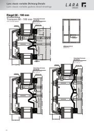
Sealing system<br />
The standard mullion is usually constructed in level 3 [E3],<br />
while the standard transom is constructed in level 2 [E2]. If a<br />
curtain wall area needs to be divided again, the gasket on<br />
level 1 [E1] may be connected to the gasket on level 2 in an<br />
overlapping manner. If condensate from the glass rebate<br />
cannot be drained via the mullion rebate, a so called “transom<br />
drainage" may be created in the transom with the gasket on<br />
level 4 [E4]. The “Lara GF” system thus allows for 4 different<br />
gasket levels in the 50 mm and 60 mm construction widths<br />
and for 3 different gasket levels in the 80 mm construction<br />
width.<br />
standard<br />
construction<br />
sealing system<br />
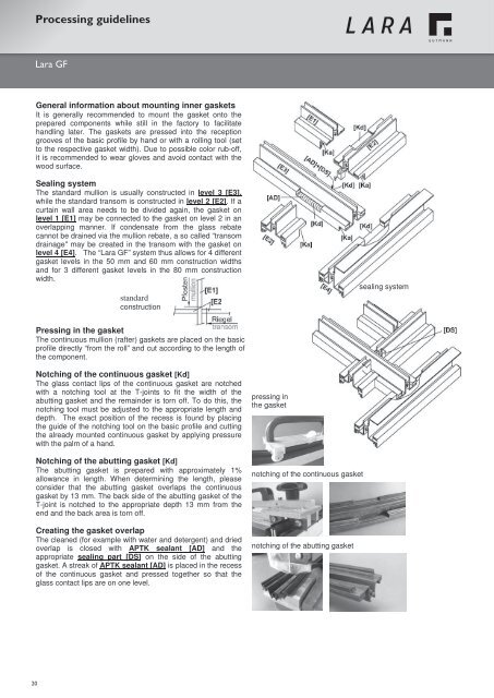
Pressing in the gasket<br />
The continuous mullion (rafter) gaskets are placed on the basic<br />
profile directly “from the roll” and cut according to the length of<br />
the component.<br />
Notching of the continuous gasket [Kd]<br />
The glass contact lips of the continuous gasket are notched<br />
with a notching tool at the T-joints to fit the width of the<br />
abutting gasket and the remainder is torn off. To do this, the<br />
notching tool must be adjusted to the appropriate length and<br />
depth. The exact position of the recess is found by placing<br />
the guide of the notching tool on the basic profile and cutting<br />
the already mounted continuous gasket by applying pressure<br />
with the palm of a hand.<br />
Notching of the abutting gasket [Kd]<br />
The abutting gasket is prepared with approximately 1%<br />
allowance in length. When determining the length, please<br />
consider that the abutting gasket overlaps the continuous<br />
gasket by 13 mm. The back side of the abutting gasket of the<br />
T-joint is notched to the appropriate depth 13 mm from the<br />
end and the back area is torn off.<br />
Creating the gasket overlap<br />
The cleaned (for example with water and detergent) and dried<br />
overlap is closed with APTK sealant [AD] and the<br />
appropriate sealing part [DS] on the side of the abutting<br />
gasket. A streak of APTK sealant [AD] is placed in the recess<br />
of the continuous gasket and pressed together so that the<br />
glass contact lips are on one level.<br />
pressing in<br />
the gasket<br />
notching of the continuous gasket<br />
notching of the abutting gasket<br />
20