Bedienungsanleitungen
Bedienungsanleitungen
Bedienungsanleitungen

Sie wollen auch ein ePaper? Erhöhen Sie die Reichweite Ihrer Titel.
YUMPU macht aus Druck-PDFs automatisch weboptimierte ePaper, die Google liebt.
Bedienungsanleitung<br />
Instruction Manual<br />
K 35/4<br />
Version 1.a ©6/04<br />
JCS<br />
WE.3402<br />
Bedienungsanleitung<br />
Instruction Manual<br />
K 35/4<br />
Version 1.a ©6/04<br />
JCS<br />
WE.3402
Bedienungsanleitung K 35/4 Seite 2<br />
______________________________________________________________________________________________________________________<br />
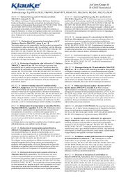
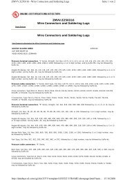
Abb. 1<br />
Lasche Bügel Rändelschrauben Teleskopgriffe<br />
Latch Holder Knurled screw Telescopic handles<br />
Pos. 5 Pos. 3 Pos. 2 Pos. 1<br />
Presseinsätze Preßkopf<br />
Dies<br />
Crimping head<br />
Pos. 6 Pos. 4<br />
Abb. 2<br />
Bedienungsanleitung K 35/4 Seite 2<br />
________________________________________________________________________________________________________________<br />
Abb. 1<br />
Lasche Bügel Rändelschrauben Teleskopgriffe<br />
Latch Holder Knurled screw Telescopic handles<br />
Pos. 5 Pos. 3 Pos. 2 Pos. 1<br />
Presseinsätze Preßkopf<br />
Dies<br />
Crimping head<br />
Pos. 6 Pos. 4<br />
Abb. 2
Bedienungsanleitung K 35/4 Seite 3<br />
______________________________________________________________________________________________________________________<br />
Inhaltsangabe<br />
1. Einleitung<br />
2. Gewährleistung<br />
3. Hinweise zum bestimmungsgemäßen Gebrauch<br />
3.1. Bedienung des Preßwerkzeuges<br />
3.2. Erläuterung des Anwendungsbereiches<br />
3.3. Wartungshinweise<br />
3.4. Aufbewahrung und Transport des Preßwerkzeuges<br />
3.5. Hinweis, welche (Ersatz-) Teile vom Kunden selber ausgewechselt werden dürfen.<br />
4. Technische Daten<br />
Symbole<br />
Sicherheitstechnische Hinweise<br />
Bitte unbedingt beachten, um Personenund<br />
Umweltschäden zu vermeiden.<br />
Anwendungstechnische Hinweise<br />
Bitte unbedingt beachten, um Schäden am<br />
Gerät zu vermeiden.<br />
Bedienungsanleitung K 35/4 Seite 3<br />
________________________________________________________________________________________________________________<br />
Inhaltsangabe<br />
1. Einleitung<br />
2. Gewährleistung<br />
3. Hinweise zum bestimmungsgemäßen Gebrauch<br />
3.1. Bedienung des Preßwerkzeuges<br />
3.2. Erläuterung des Anwendungsbereiches<br />
3.3. Wartungshinweise<br />
3.4. Aufbewahrung und Transport des Preßwerkzeuges<br />
3.5. Hinweis, welche (Ersatz-) Teile vom Kunden selber ausgewechselt werden dürfen.<br />
4. Technische Daten<br />
Symbole<br />
Sicherheitstechnische Hinweise<br />
Bitte unbedingt beachten, um Personenund<br />
Umweltschäden zu vermeiden.<br />
Anwendungstechnische Hinweise<br />
Bitte unbedingt beachten, um Schäden am<br />
Gerät zu vermeiden.
Bedienungsanleitung K 35/4 Seite 4<br />
______________________________________________________________________________________________________________________<br />
Kurzinspektion vor Inbetriebnahme<br />
Bitte prüfen Sie als erstes, ob Sie alle im Lieferumfang angeführten Teile erhalten haben.<br />
Lieferumfang:<br />
1 mechanisches Preßgerät Typ K 35/4<br />
1 Bedienungsanleitung<br />
Bedienungsanleitung<br />
für das mechanische Preßwerkzeug Typ K 35/4, Seriennummer ............................<br />
1. Einleitung<br />
Vor Benutzung Ihres Preßwerkzeuges lesen Sie sich die Bedienungsanleitung<br />
sorgfältig durch.<br />
Benutzen Sie dieses Werkzeug ausschließlich für den bestimmungsgemäßen Gebrauch.<br />
2. Gewährleistung<br />
Die Gewährleistung bei sachgemäßer Bedienung beträgt 12 Monate ab Lieferdatum.<br />
Bedienungsanleitung K 35/4 Seite 4<br />
____________________________________________________________________________________________________________________<br />
Kurzinspektion vor Inbetriebnahme<br />
Bitte prüfen Sie als erstes, ob Sie alle im Lieferumfang angeführten Teile erhalten haben.<br />
Lieferumfang:<br />
1 mechanisches Preßgerät Typ K 35/4<br />
1 Bedienungsanleitung<br />
Bedienungsanleitung<br />
für das mechanische Preßwerkzeug Typ K 35/4, Seriennummer ............................<br />
1. Einleitung<br />
Vor Benutzung Ihres Preßwerkzeuges lesen Sie sich die Bedienungsanleitung<br />
sorgfältig durch.<br />
Benutzen Sie dieses Werkzeug ausschließlich für den bestimmungsgemäßen Gebrauch.<br />
2. Gewährleistung<br />
Die Gewährleistung bei sachgemäßer Bedienung beträgt 12 Monate ab Lieferdatum.
Bedienungsanleitung K 35/4 Seite 5<br />
______________________________________________________________________________________________________________________<br />
3. Hinweise zum bestimmungsgemäßen Gebrauch<br />
Bei der K 35/4 handelt es sich um ein mechanisches Preßwerkzeug für auswechselbare<br />
Einsätze.<br />
3.1. Bedienung des Preßwerkzeuges<br />
Als erstes wird für die gewünschte Anwendung der geeignete Preßeinsatz (Pos.-Nr. 6) bereitgelegt.<br />
Anschließend wird die Lasche (Pos.-Nr. 5) ausgerastet und der Preßkopf (Pos.-Nr. 4)<br />
geöffnet. Die Preßeinsätze werden nacheinander (Pos.-Nr. 5) in den geöffneten Kopf bis zum<br />
Einrasten eingeschoben. Anschließend wird das Verbindungsmaterial eingelegt und der<br />
Preßkopf geschlossen.<br />
Die für die Verpressung notwendige Handkraft kann durch Verstellen der Teleskophandgriffe<br />
(Pos.-Nr. 1) angepaßt werden. Hierzu müssen die Rändelschrauben (Pos.-Nr. 2) gelöst , die<br />
Teleskopgriffe herausgezogen und anschließend die Rändelschrauben wieder festgeschraubt<br />
werden.<br />
Achtung<br />
Die Zangengriffe dürfen nicht über den Anschlag hinaus mit Kraft geöffnet werden.<br />
Der Preßvorgang wird gekennzeichnet durch das Schließen der Preßeinsätze. Dabei befindet<br />
sich das auf das Kabel aufgeschobene Verbindungsmaterial bei geschlossenem Preßkopf (Pos.-<br />
Nr. 4) in dem Preßprofil der stationären Hälfte des Preßeinsatzes. Der auf der Kolbenstange<br />
sitzende bewegliche Teil des Preßeinsatzes bewegt sich dabei auf die Preßstelle zu.<br />
Bedienungsanleitung K 35/4 Seite 5<br />
____________________________________________________________________________________________________________________<br />
3. Hinweise zum bestimmungsgemäßen Gebrauch<br />
Bei der K 35/4 handelt es sich um ein mechanisches Preßwerkzeug für auswechselbare<br />
Einsätze.<br />
3.1. Bedienung des Preßwerkzeuges<br />
Als erstes wird für die gewünschte Anwendung der geeignete Preßeinsatz (Pos.-Nr. 6) bereitgelegt.<br />
Anschließend wird der Riegel (Pos.-Nr. 3) ausgerastet und der Preßkopf (Pos.-Nr. 4)<br />
geöffnet. Die Preßeinsätze werden nacheinander seitlich unter Betätigung der Druckstücke<br />
(Pos.-Nr. 5) in den geöffneten Kopf eingeschoben. Anschließend wird das Verbindungsmaterial<br />
eingelegt und der Preßkopf geschlossen.<br />
Die für die Verpressung notwendige Handkraft kann durch Verstellen der Teleskophandgriffe<br />
(Pos.-Nr. 1) angepaßt werden. Hierzu müssen die Rändelschrauben (Pos.-Nr. 2) gelöst , die<br />
Teleskopgriffe herausgezogen und anschließend die Rändelschrauben wieder festgeschraubt<br />
werden.<br />
Achtung<br />
Die Zangengriffe dürfen nicht über den Anschlag hinaus mit Kraft geöffnet werden.<br />
Der Preßvorgang wird gekennzeichnet durch das Schließen der Preßeinsätze. Dabei befindet<br />
sich das auf das Kabel aufgeschobene Verbindungsmaterial bei geschlossenem Preßkopf (Pos.-<br />
Nr. 4) in dem Preßprofil der stationären Hälfte des Preßeinsatzes. Der auf der Kolbenstange<br />
sitzende bewegliche Teil des Preßeinsatzes bewegt sich dabei auf die Preßstelle zu.
Bedienungsanleitung K 35/4 Seite 6<br />
______________________________________________________________________________________________________________________<br />
Eine Preßvorgang ist abgeschlossen, wenn die Presseinsätze (Pos.-Nr. 6) vollständig<br />
zusammengefahren sind.<br />
Die Preßeinsätze (Pos.-Nr. 6) werden unter Drücken der Druckstücke (Pos.-Nr. 5) seitlich aus<br />
dem Werkzeug herausgenommen.<br />
Anschließend kann entweder ein weiterer Preßvorgang vorgenommen werden oder das<br />
Verbindungsmaterial aus dem Preßkopf (Pos.-Nr. 4) herausgenommen werden.<br />
3.2. Erläuterung des Anwendungsbereiches<br />
Unser mechanisches Preßwerkzeug vom Typ K 35/4 verfügt über eine große Anzahl<br />
verschiedener Preßeinsätze (Pos.-Nr. 6) zum Verpressen von isoliertem und unisoliertem<br />
Verbindungsmaterial aus Cu und Al.<br />
Tabelle 1<br />
Preßbereich Verbindungsmaterial<br />
_______________________________________________________________________________________________________________<br />
a 6-150 mm² Rohrkabelschuhe und Verbinder „Normalausführung“<br />
___________________________________________________________________________________________________________<br />
b 6-95 mm² Preßkabelschuhe und Verbinder DIN 46235/DIN 46267<br />
_______________________________________________________________________________________________________________<br />
c 10-70 mm² Aluminium Kabelschuhe und Verbinder<br />
___________________________________________________________________________________________________________<br />
Bedienungsanleitung K 35/4 Seite 6<br />
________________________________________________________________________________________________________________<br />
Eine Preßvorgang ist abgeschlossen, wenn die Preßeinsätze (Pos.-Nr. 6) vollständig<br />
zusammengefahren sind.<br />
Die Preßeinsätze (Pos.-Nr. 6) werden unter Drücken der Druckstücke (Pos.-Nr. 5) seitlich aus<br />
dem Werkzeug herausgenommen.<br />
Anschließend kann entweder ein weiterer Preßvorgang vorgenommen werden oder das<br />
Verbindungsmaterial aus dem Preßkopf (Pos.-Nr. 4) herausgenommen werden.<br />
3.2. Erläuterung des Anwendungsbereiches<br />
Unser mechanisches Preßwerkzeug vom Typ K 35/4 verfügt über eine große Anzahl<br />
verschiedener Preßeinsätze (Pos.-Nr. 6) zum Verpressen von isoliertem und unisoliertem<br />
Verbindungsmaterial aus Cu und Al.<br />
Tabelle 1<br />
Preßbereich Verbindungsmaterial<br />
_______________________________________________________________________________________________________________<br />
a 6-150 mm² Rohrkabelschuhe und Verbinder „Normalausführung“<br />
___________________________________________________________________________________________________________<br />
b 6-95 mm² Preßkabelschuhe und Verbinder DIN 46235/DIN 46267<br />
_______________________________________________________________________________________________________________<br />
c 10-70 mm² Aluminium Kabelschuhe und Verbinder<br />
___________________________________________________________________________________________________________
Bedienungsanleitung K 35/4 Seite 7<br />
______________________________________________________________________________________________________________________<br />
Fortsetzung Tabelle 1<br />
Preßbereich Verbindungsmaterial<br />
_______________________________________________________________________________________________________________<br />
d 25-50 mm² Preßverbinder für zugfeste Verbindungen von Aldrey-Seilen<br />
nach DIN 48201, Blatt 6<br />
___________________________________________________________________________________________________________<br />
e 10-120 sm mm² Runddrückeinsätze für Al- und Cu-Sektorleiter<br />
35-150 se mm²<br />
_______________________________________________________________________________________________________________<br />
f 10-16 mm² Quetschkabelschuhe DIN 46234,<br />
Stiftkabelschuhe DIN 46230<br />
___________________________________________________________________________________________________________<br />
g 10-16 mm² Isolierte Quetschkabelschuhe<br />
_______________________________________________________________________________________________________________<br />
h 10-25 mm² Rohrkabelschuhe für feindrähtige Leiter<br />
_______________________________________________________________________________________________________________<br />
i 4-35 mm² C-Abzweigklemmen<br />
_______________________________________________________________________________________________________________<br />
j 10-70 mm² isolierte Rohrkabelschuhe und Verbinder sowie isolierte<br />
Stiftkabelschuhe<br />
_______________________________________________________________________________________________________________<br />
k 0,5-16 mm² Kabelschuhe und Verbinder aus Nickel und Edelstahl<br />
_______________________________________________________________________________________________________________<br />
l 10-50 mm² Aderendhülsen<br />
_______________________________________________________________________________________________________________<br />
m 2x4-2x16 mm² Zwillingsaderendhülsen<br />
_______________________________________________________________________________________________________________<br />
Bedienungsanleitung K 35/4 Seite 7<br />
____________________________________________________________________________________________________________________<br />
Fortsetzung Tabelle 1<br />
Preßbereich Verbindungsmaterial<br />
_______________________________________________________________________________________________________________<br />
d 25-50 mm² Preßverbinder für zugfeste Verbindungen von Aldrey-Seilen<br />
nach DIN 48201, Blatt 6<br />
___________________________________________________________________________________________________________<br />
e 10-120 sm mm² Runddrückeinsätze für Al- und Cu-Sektorleiter<br />
35-150 se mm²<br />
_______________________________________________________________________________________________________________<br />
f 10-16 mm² Quetschkabelschuhe DIN 46234,<br />
Stiftkabelschuhe DIN 46230<br />
___________________________________________________________________________________________________________<br />
g 10-16 mm² Isolierte Quetschkabelschuhe<br />
_______________________________________________________________________________________________________________<br />
h 10-25 mm² Rohrkabelschuhe für feindrähtige Leiter<br />
_______________________________________________________________________________________________________________<br />
i 4-35 mm² C-Abzweigklemmen<br />
_______________________________________________________________________________________________________________<br />
j 10-70 mm² isolierte Rohrkabelschuhe und Verbinder sowie isolierte<br />
Stiftkabelschuhe<br />
_______________________________________________________________________________________________________________<br />
k 0,5-16 mm² Kabelschuhe und Verbinder aus Nickel und Edelstahl<br />
_______________________________________________________________________________________________________________<br />
l 10-50 mm² Aderendhülsen<br />
_______________________________________________________________________________________________________________<br />
m 2x4-2x16 mm² Zwillingsaderendhülsen<br />
_______________________________________________________________________________________________________________
Bedienungsanleitung K 35/4 Seite 8<br />
______________________________________________________________________________________________________________________<br />
Tabelle 2 (Fortsetzung)<br />
Preßbereich Verbindungsmaterial<br />
_______________________________________________________________________________________________________________<br />
n 10-50 mm² Aderendhülsen für verdichtete feindrähtige Leiter<br />
_______________________________________________________________________________________________________________<br />
o 2x4-2x16 mm² Zwillingsaderendhülsen für verdichtete feindrähtige Leiter<br />
Sollten andere Verbindungsmaterialien verpreßt werden müssen, ist eine Rücksprache mit dem<br />
Werk zwingend erforderlich.<br />
Achtung<br />
Es dürfen keine unter Spannung stehenden Teile verpreßt werden.<br />
Vor Arbeitsbeginn ist ein spannungsfreier Zustand der zu verpressenden Verbindung<br />
sicherzustellen.<br />
Achtung<br />
Es dürfen nur die für das Material vorgesehenen Preßeinsätze verwendet werden.<br />
3.3. Wartungshinweise<br />
Das mechanische Preßwerkzeug ist nach jedem Gebrauch zu reinigen und ein trockener<br />
Zustand ist vor Einlagerung sicherzustellen. Das Werkzeug ist im Prinzip wartungsfrei,<br />
lediglich die Bolzenverbindungen sind regelmäßig leicht einzuölen.<br />
Bedienungsanleitung K 35/4 Seite 8<br />
________________________________________________________________________________________________________________<br />
Tabelle 2 (Fortsetzung)<br />
Preßbereich Verbindungsmaterial<br />
_______________________________________________________________________________________________________________<br />
n 10-50 mm² Aderendhülsen für verdichtete feindrähtige Leiter<br />
_______________________________________________________________________________________________________________<br />
o 2x4-2x16 mm² Zwillingsaderendhülsen für verdichtete feindrähtige Leiter<br />
Sollten andere Verbindungsmaterialien verpreßt werden müssen, ist eine Rücksprache mit dem<br />
Werk zwingend erforderlich.<br />
Achtung<br />
Es dürfen keine unter Spannung stehenden Teile verpreßt werden.<br />
Vor Arbeitsbeginn ist ein spannungsfreier Zustand der zu verpressenden Verbindung<br />
sicherzustellen.<br />
Achtung<br />
Es dürfen nur die für das Material vorgesehenen Preßeinsätze verwendet werden.<br />
3.3. Wartungshinweise<br />
Das mechanische Preßwerkzeug ist nach jedem Gebrauch zu reinigen und ein trockener<br />
Zustand ist vor Einlagerung sicherzustellen. Das Werkzeug ist im Prinzip wartungsfrei,<br />
lediglich die Bolzenverbindungen sind regelmäßig leicht einzuölen.
Bedienungsanleitung K 35/4 Seite 9<br />
______________________________________________________________________________________________________________________<br />
3.4. Aufbewahrung und Transport des Preßwerkzeuges<br />
Um das Preßwerkzeug einschließlich der Einsätze vor Beschädigungen zu schützen, sollte das<br />
Preßwerkzeug nach Gebrauch und nachdem es gesäubert worden ist, in den Transportkoffer<br />
gelegt werden, der dann anschließend sicher zu verschließen ist.<br />
3.5. Hinweis welche (Ersatz-) Teile vom Kunden selber ausgetauscht werden dürfen.<br />
Im Rahmen des bestimmungsgemäßen Gebrauchs dürfen vom Kunden nur die<br />
Werkzeugeinsätze gewechselt werden.<br />
4. Technische Daten<br />
Gewicht des kompl. Werkzeuges:<br />
Länge des Werkzeuges:<br />
Preßkopf:<br />
ca. 1,900 kg<br />
ca. 420-590 mm<br />
360° drehbar<br />
Bedienungsanleitung K 35/4 Seite 9<br />
________________________________________________________________________________________________________________<br />
3.4. Aufbewahrung und Transport des Preßwerkzeuges<br />
Um das Preßwerkzeug einschließlich der Einsätze vor Beschädigungen zu schützen, sollte das<br />
Preßwerkzeug nach Gebrauch und nachdem es gesäubert worden ist, in den Transportkoffer<br />
gelegt werden, der dann anschließend sicher zu verschließen ist.<br />
3.5. Hinweis welche (Ersatz-) Teile vom Kunden selber ausgetauscht werden dürfen.<br />
Im Rahmen des bestimmungsgemäßen Gebrauchs dürfen vom Kunden nur die<br />
Werkzeugeinsätze gewechselt werden.<br />
4. Technische Daten<br />
Gewicht des kompl. Werkzeuges:<br />
Länge des Werkzeuges:<br />
Preßkopf:<br />
ca. 1,900 kg<br />
ca. 420-590 mm<br />
360° drehbar
Instruction manual K 35/4 page 10<br />
________________________________________________________________________________________________________________<br />
Instruction Manual<br />
K 35/4<br />
Index<br />
1. Introduction<br />
2. Warranty<br />
3. Remarks in respect of the determined use<br />
3.1. Operation of the units<br />
3.2. Explanation of the application range<br />
3.3. Service and maintenance Instructions<br />
3.4. Storage and transport of the crimping unit.<br />
3.5. Reference as to which (spare-) parts can be exchanged by the customer.<br />
4. Technical data<br />
Symbols<br />
Safety Warnings<br />
Please do not disregard to avoid injuries and environmental damage.<br />
Application Warnings<br />
Please do not disregard to avoid damaging the tool.<br />
Instruction manual K 35/4 page 10<br />
________________________________________________________________________________________________________________<br />
Instruction Manual<br />
K 35/4<br />
Index<br />
1. Introduction<br />
2. Warranty<br />
3. Remarks in respect of the determined use<br />
3.1. Operation of the units<br />
3.2. Explanation of the application range<br />
3.3. Service and maintenance Instructions<br />
3.4. Storage and transport of the crimping unit.<br />
3.5. Reference as to which (spare-) parts can be exchanged by the customer.<br />
4. Technical data<br />
Symbols<br />
Safety Warnings<br />
Please do not disregard to avoid injuries and environmental damage.<br />
Application Warnings<br />
Please do not disregard to avoid damaging the tool.
Instruction Manual K 35/4 page 11<br />
________________________________________________________________________________________________________________<br />
Instruction Manual<br />
for the hand-hydraulic crimping tool Type K 35/4, Serial-No. ............................<br />
1. Introduction<br />
Attention<br />
Before starting to use the tool please read the instruction manual carefully.<br />
Use this tool exclusively for its determined use.<br />
2. Warranty<br />
If correct operation is guaranteed our warranty is 12 months from the time of delivery.<br />
3. Remarks in respect of the determined use<br />
The K 35/4 is a mechanical crimping tool for interchangeable dies.<br />
3.1. Operation of the unit<br />
First you have to select the right dies (Pos.-No. 6) for the intended application.<br />
The crimping head has to be opened by unhooking the latch (Pos.-No. 5). Afterwards dies<br />
will be inserted consecutively into the crimping head.<br />
Instruction manual K 35/4 page 11<br />
________________________________________________________________________________________________________________<br />
Instruction Manual<br />
for the hand-hydraulic crimping tool Type K 35/4, Serial-No. ............................<br />
1. Introduction<br />
Attention<br />
Before starting to use the tool please read the instruction manual carefully.<br />
Use this tool exclusively for its determined use.<br />
2. Warranty<br />
If correct operation is guaranteed our warranty is 12 months from the time of delivery.<br />
3. Remarks in respect of the determined use<br />
The K 35/4 is a mechanical crimping tool for interchangeable dies.<br />
3.1. Operation of the unit<br />
First you have to select the right dies (Pos.-No. 6) for the intended application.<br />
The crimping head has to be opened by unhooking the latch (Pos.-No. 5). Afterwards dies<br />
will be inserted consecutively into the crimping head.
Instruction Manual K 35/4 page 12<br />
________________________________________________________________________________________________________________<br />
Then the connecting material must be positioned in the crimping head and the crimping<br />
head must be closed again.<br />
The necessary hand forces can be adjusted with the telescope handles. To do that you have<br />
to loosen the screws (Pos.-No. 2), pull them out and fix them again.<br />
The crimping process is defined by the closing motion of the dies. During that process the<br />
connecting material is positioned in the stationary half of the die whereas the moving part<br />
of the die is approaching the compression point. A crimping process is terminated when<br />
the dies contacted. After the crimping process has been finished the latch (Pos.-No. 3) has<br />
to be opened again and the connecting material has to be removed.<br />
3.2. Explanation of the application range<br />
Our mechanical crimping tool type K 35/4 has a large number of various dies (Pos.-No. 6)<br />
available to crimp copper, aluminium and other connecting material according to the<br />
determined use.<br />
Table 1<br />
Crimping range Connecting material<br />
___________________________________________________________________________________________________________<br />
a 6-150 mm² Tubular cable lugs and connectors „Standard type“<br />
________________________________________________________________________________________________________<br />
b 6-95 mm² Compression cable lugs and joints DIN 46235/DIN 46267<br />
___________________________________________________________________________________________________________<br />
Instruction manual K 35/4 page 12<br />
________________________________________________________________________________________________________________<br />
Then the connecting material must be positioned in the crimping head and the crimping<br />
head must be closed again.<br />
The necessary hand forces can be adjusted with the telescope handles. To do that you have<br />
to loosen the screws (Pos.-No. 2), pull them out and fix them again.<br />
The crimping process is defined by the closing motion of the dies. During that process the<br />
connecting material is positioned in the stationary half of the die whereas the moving part<br />
of the die is approaching the compression point. A crimping process is terminated when<br />
the dies contacted. After the crimping process has been finished the latch (Pos.-No. 3) has<br />
to be opened again and the connecting material has to be removed.<br />
3.2. Explanation of the application range<br />
Our mechanical crimping tool type K 35/4 has a large number of various dies (Pos.-No. 6)<br />
available to crimp copper, aluminium and other connecting material according to the<br />
determined use.<br />
Table 1<br />
Crimping range Connecting material<br />
___________________________________________________________________________________________________________<br />
a 6-150 mm² Tubular cable lugs and connectors „Standard type“<br />
________________________________________________________________________________________________________<br />
b 6-95 mm² Compression cable lugs and joints DIN 46235/DIN 46267<br />
___________________________________________________________________________________________________________
Instruction Manual K 35/4 page 13<br />
________________________________________________________________________________________________________________<br />
Crimping range Connecting material<br />
___________________________________________________________________________________________________________<br />
c 10-70 mm² Aluminium cable lugs and connectors<br />
________________________________________________________________________________________________________<br />
d 25-50 mm² Compression joints for full-tension connections for Aldrey<br />
conductors acc. to DIN 48201, sheet 6<br />
________________________________________________________________________________________________________<br />
e 10-120 sm mm² Pre-rounding dies for Al- and Cu-Sector-conductors<br />
35-150 se mm²<br />
___________________________________________________________________________________________________________<br />
f 10-16 mm² Solderless Terminals DIN 46234, Pin terminals DIN 46230<br />
________________________________________________________________________________________________________<br />
g 10-16 mm² Insulated solderless terminals<br />
___________________________________________________________________________________________________________<br />
h 10-25 mm² Tubular cable lugs for fine-stranded conductors<br />
___________________________________________________________________________________________________________<br />
i 4-35 mm² C-clamps<br />
___________________________________________________________________________________________________________<br />
j 10-70 mm² Pre-insulated tubular cable lugs and connectors,<br />
insulated pin cable lugs<br />
___________________________________________________________________________________________________________<br />
k 0,5-16 mm² Tubular nickel and stainless steel cable lugs and connectors<br />
___________________________________________________________________________________________________________<br />
l 10-70 mm² oval shape compression joints acc. to DIN 48217 and<br />
compression dead ends<br />
___________________________________________________________________________________________________________<br />
m 10-50 mm² Cable end-sleeves<br />
___________________________________________________________________________________________________________<br />
Instruction manual K 35/4 page 13<br />
________________________________________________________________________________________________________________<br />
Crimping range Connecting material<br />
___________________________________________________________________________________________________________<br />
c 10-70 mm² Aluminium cable lugs and connectors<br />
________________________________________________________________________________________________________<br />
d 25-50 mm² Compression joints for full-tension connections for Aldrey<br />
conductors acc. to DIN 48201, sheet 6<br />
________________________________________________________________________________________________________<br />
e 10-120 sm mm² Pre-rounding dies for Al- and Cu-Sector-conductors<br />
35-150 se mm²<br />
___________________________________________________________________________________________________________<br />
f 10-16 mm² Solderless Terminals DIN 46234, Pin terminals DIN 46230<br />
________________________________________________________________________________________________________<br />
g 10-16 mm² Insulated solderless terminals<br />
___________________________________________________________________________________________________________<br />
h 10-25 mm² Tubular cable lugs for fine-stranded conductors<br />
___________________________________________________________________________________________________________<br />
i 4-35 mm² C-clamps<br />
___________________________________________________________________________________________________________<br />
j 10-70 mm² Pre-insulated tubular cable lugs and connectors,<br />
insulated pin cable lugs<br />
___________________________________________________________________________________________________________<br />
k 0,5-16 mm² Tubular nickel and stainless steel cable lugs and connectors<br />
___________________________________________________________________________________________________________<br />
l 10-70 mm² oval shape compression joints acc. to DIN 48217 and<br />
compression dead ends<br />
___________________________________________________________________________________________________________<br />
m 10-50 mm² Cable end-sleeves<br />
___________________________________________________________________________________________________________
Instruction Manual K 35/4 page 14<br />
________________________________________________________________________________________________________________<br />
Crimping range Connecting material<br />
___________________________________________________________________________________________________________<br />
n 2x4-2x16 mm² Twin cable end-sleeves<br />
___________________________________________________________________________________________________________<br />
o 10-50 mm² Cable end-sleeves for compacted fine stranded conductors<br />
___________________________________________________________________________________________________________<br />
p 2x4-2x16 mm² Twin cable end-sleeves for compacted fine stranded conductors<br />
Attention<br />
Do only crimp copper and Al conducting material or special connecting<br />
material mentioned in table 2.<br />
If different conducting materials have to be crimped, please contact the manufacturer.<br />
Attention<br />
Do not crimp on or use near live circuits. This tool is not insulated.<br />
Before starting to crimp please make sure that all parts involved in the crimping process<br />
are not energised.<br />
3.3. Service and maintenance instruction<br />
This mechanical crimping unit has to be cleaned and dried after use. The unit is basically<br />
maintenance-free, only the bolt joints have to be oiled regularly.<br />
Instruction manual K 35/4 page 14<br />
________________________________________________________________________________________________________________<br />
Crimping range Connecting material<br />
___________________________________________________________________________________________________________<br />
n 2x4-2x16 mm² Twin cable end-sleeves<br />
___________________________________________________________________________________________________________<br />
o 10-50 mm² Cable end-sleeves for compacted fine stranded conductors<br />
___________________________________________________________________________________________________________<br />
p 2x4-2x16 mm² Twin cable end-sleeves for compacted fine stranded conductors<br />
Attention<br />
Do only crimp copper and Al conducting material or special connecting<br />
material mentioned in table 2.<br />
If different conducting materials have to be crimped, please contact the manufacturer.<br />
Attention<br />
Do not crimp on or use near live circuits. This tool is not insulated.<br />
Before starting to crimp please make sure that all parts involved in the crimping process<br />
are not energised.<br />
3.3. Service and maintenance instruction<br />
This mechanical crimping unit has to be cleaned and dried after use. The unit is basically<br />
maintenance-free, only the bolt joints have to be oiled regularly.
Instruction Manual K 35/4 page 15<br />
________________________________________________________________________________________________________________<br />
3.4. Storage and transport of the crimping tool<br />
In order to protect the tool against damages it has to be cleaned carefully after every use<br />
and be put into the transportation case which has to be closed safely. Into this case you can<br />
put 17 dies and the instruction manual.<br />
4. Troubleshooting<br />
There is yet no information about problems in respect of the performance of the tool.<br />
5. Technical Data<br />
Crimping head can be turned 360° in a pressure-free state.<br />
Weight of the tool:<br />
ca. 1,9 kg<br />
Length of the entire tool: 420-590 mm (infinitely variable adjustment)<br />
Instruction manual K 35/4 page 15<br />
________________________________________________________________________________________________________________<br />
3.4. Storage and transport of the crimping tool<br />
In order to protect the tool against damages it has to be cleaned carefully after every use<br />
and be put into the transportation case which has to be closed safely. Into this case you can<br />
put 17 dies and the instruction manual.<br />
4. Troubleshooting<br />
There is yet no information about problems in respect of the performance of the tool.<br />
5. Technical Data<br />
Crimping head can be turned 360° in a pressure-free state.<br />
Weight of the tool:<br />
ca. 1,9 kg<br />
Length of the entire tool: 420-590 mm (infinitely variable adjustment)
Service HK60/18 Seite/page 16<br />
__________________________________________________________________________________________________________________<br />
DEUTSCHLAND:<br />
FRANKREICH:<br />
GROSSBRITTANIEN:<br />
POLEN/UKRAINE:<br />
Klauke Remscheid<br />
Herr Radtke<br />
Auf dem Knapp 46<br />
42855 Remscheid<br />
Tel.: ++49 (0)2191/907-168<br />
Fax: ++49 (0)2191/907-242<br />
e-mail: service@klauke.textron.com<br />
KLAUKE FRANCE<br />
Mr. Weiten<br />
16, Rue Saint-Louis<br />
Z.I. Actisud<br />
57150 Creutzwald (France)<br />
Tel.: ++33-3-87298470<br />
Fax: ++33-3-87298479<br />
E-MAIL: klauke.france@free.fr<br />
Norwich Instrument Services<br />
Mr. Norman Cockburn<br />
32 Hellesdon Park Road<br />
Drayton High Road<br />
Norwich NR6 5DR (UK)<br />
Tel.: 0044-1603-416900<br />
Fax: 0044-1603-416902<br />
E-Mail: norman@nisltd.co.uk<br />
RB Brexim S.A.<br />
Marynin 7a<br />
05-825 Grodzisk Mazowiecki (Polen)<br />
Tel.: ++48-22-7920273 oder 75<br />
Fax: ++48-22-7923055<br />
E-MAIL: RB.office@brexim.pl<br />
PORTUGAL:<br />
NIEDERLANDE:<br />
ÖSTERREICH:<br />
SPANIEN/ANDORRA:<br />
ITALIEN:<br />
Palissy Galvani Electricidade Lda.<br />
Mr. Ana Pereira<br />
Rua Serpa Pinto, 15-A/P<br />
1200 Lisboa (Portugal)<br />
Tel.: ++351-21-3223400<br />
Fax: ++351-21-3223410<br />
H.K. Electric B.V.<br />
Mr. Kleijn<br />
De Steegen 7<br />
5321 JZ Hedel (Niederlande)<br />
Tel.: ++31-73-5997599<br />
Fax: ++31-73-5997590<br />
E-Mail: m.kleijn@hkelectric.nl<br />
KLAUKE Handelsgesellschaft mbH<br />
Mr. Acham<br />
Kaiser-Franz-Josef-Str. 9<br />
1230 Wien (Österreich)<br />
Tel.: ++43-1-8893436<br />
Fax: ++43-1-8893433<br />
E-MAIL: office@klauke.at<br />
Gave Electro S.A.<br />
Mr. Fernando Carvalho<br />
Paratge Coll-Blanc, S/N<br />
Aptdo. 12<br />
08430 La Roca del Valles,<br />
Barcelona (Spanien)<br />
Tel.: ++34-93-8422212<br />
Fax: ++34-93-8422227<br />
E-MAIL: gave@gave.com<br />
F.B. Spa<br />
Mr. Victor Drozdowski<br />
Via Buonarroti, 11<br />
61030 Borgaccio di Soltara (PU) (Italy)<br />
Tel.: ++39-0721-892168<br />
Fax: ++39-0721-879602<br />
E-MAIL: produzione@fb-avvolgitori.it<br />
Service Seite/page 16<br />
__________________________________________________________________________________________________________________<br />
DEUTSCHLAND:<br />
FRANKREICH:<br />
GROSSBRITTANIEN:<br />
POLEN/UKRAINE:<br />
Klauke Remscheid<br />
Herr Radtke<br />
Auf dem Knapp 46<br />
42855 Remscheid<br />
Tel.: ++49 (0)2191/907-168<br />
Fax: ++49 (0)2191/907-242<br />
e-mail: service@klauke.textron.com<br />
KLAUKE FRANCE<br />
Mr. Weiten<br />
16, Rue Saint-Louis<br />
Z.I. Actisud<br />
57150 Creutzwald (France)<br />
Tel.: ++33-3-87298470<br />
Fax: ++33-3-87298479<br />
E-MAIL: klauke.france@free.fr<br />
Norwich Instrument Services<br />
Mr. Norman Cockburn<br />
32 Hellesdon Park Road<br />
Drayton High Road<br />
Norwich NR6 5DR (UK)<br />
Tel.: 0044-1603-416900<br />
Fax: 0044-1603-416902<br />
E-Mail: norman@nisltd.co.uk<br />
RB Brexim S.A.<br />
Marynin 7a<br />
05-825 Grodzisk Mazowiecki (Polen)<br />
Tel.: ++48-22-7920273 oder 75<br />
Fax: ++48-22-7923055<br />
E-MAIL: RB.office@brexim.pl<br />
PORTUGAL:<br />
NIEDERLANDE:<br />
ÖSTERREICH:<br />
SPANIEN/ANDORRA:<br />
ITALIEN:<br />
Palissy Galvani Electricidade Lda.<br />
Mr. Ana Pereira<br />
Rua Serpa Pinto, 15-A/P<br />
1200 Lisboa (Portugal)<br />
Tel.: ++351-21-3223400<br />
Fax: ++351-21-3223410<br />
H.K. Electric B.V.<br />
Mr. Kleijn<br />
De Steegen 7<br />
5321 JZ Hedel (Niederlande)<br />
Tel.: ++31-73-5997599<br />
Fax: ++31-73-5997590<br />
E-Mail: m.kleijn@hkelectric.nl<br />
KLAUKE Handelsgesellschaft mbH<br />
Mr. Acham<br />
Kaiser-Franz-Josef-Str. 9<br />
1230 Wien (Österreich)<br />
Tel.: ++43-1-8893436<br />
Fax: ++43-1-8893433<br />
E-MAIL: office@klauke.at<br />
Gave Electro S.A.<br />
Mr. Fernando Carvalho<br />
Paratge Coll-Blanc, S/N<br />
Aptdo. 12<br />
08430 La Roca del Valles,<br />
Barcelona (Spanien)<br />
Tel.: ++34-93-8422212<br />
Fax: ++34-93-8422227<br />
E-MAIL: gave@gave.com<br />
F.B. Spa<br />
Mr. Victor Drozdowski<br />
Via Buonarroti, 11<br />
61030 Borgaccio di Soltara (PU) (Italy)<br />
Tel.: ++39-0721-892168<br />
Fax: ++39-0721-879602<br />
E-MAIL: produzione@fb-avvolgitori.it
Service HK60/18 Seite/page 17<br />
__________________________________________________________________________________________________________________<br />
SLOWENIEN:<br />
SCHWEDEN:<br />
NORWEGEN:<br />
UNGARN:<br />
Isaria d. o.o.<br />
Mrs. Zorz<br />
Proizvdnja in trgovina<br />
Cece 2a<br />
1420 Trovlje (Slowenien)<br />
Tel.: ++386-356-31800<br />
Fax: ++386-356-3180<br />
Miltronic AB<br />
Mr. Thomas Fred<br />
Kungshagsvägen 7<br />
S-611 29 Nyköping (Schweden)<br />
Tel.: 0046-155-77700<br />
Fax: 0046-155-77702<br />
E-Mail: thomas.fred@miltronic.se<br />
Miltronic AS<br />
Mr. Hans Petter Selbo<br />
Dolasletta 5, 4308 Transby<br />
N-3421 Lierskogen (Norwegen)<br />
Tel.: 0047-32226610<br />
Fax: 0047-32226656<br />
E-Mail:<br />
hans.petter.selbo@miltronic.no<br />
Trend Elektro<br />
Mr. Istvan Imrik<br />
H-1117 Budapest<br />
Dombovari ut 5-7 (Ungarn)<br />
Tel.: 0036-1-464-3118<br />
Fax: 0036-1-464-3119<br />
E-Mail: trendelektro@freemail.hu<br />
RUSSLAND:<br />
KOREA:<br />
TÜRKEI:<br />
Schweden<br />
Bulgarien<br />
TSCHECHISCHE<br />
REPUBLIK/<br />
SLOVAKEI:<br />
Unit Mark Pro<br />
Mr. Alexander Naichouller<br />
119147 Moscow<br />
Marksistskaya 34 bldg 10 (Russland)<br />
Tel.: 007-095-7480907<br />
Fax: 007-095-7480909<br />
E-Mail: mark@unit.ru<br />
Taehyung Hydraulic Tool<br />
Mr. Kim<br />
140-5, Gamjeun-Dong, Sasang-Gu<br />
Busan 17-060 (Korea)<br />
Tel.: ++82-51-3171507<br />
Fax: ++82-51-3171507<br />
E-Mail: thhyd@hanmail.net<br />
Ünal Kardes<br />
Mr. Servet Diricanli<br />
Eski Londra Asfalti No. 6<br />
34630 Desyol-Sefaköy-<br />
Istanbul (Türkei)<br />
Tel.: 0090-212-6249204<br />
Fax: 0090-212-5924810<br />
E-Mail: sdiricanli@unalkardes.com.tr<br />
Klauke z. Nitsch s.r.o. Jiri Nitsch<br />
Jiri Nitsch<br />
M. Pujmanove 1220/31<br />
14000 Praha 4 – Prankrac<br />
(Tschechische Republik)<br />
Tel.: ++42-2-61213220<br />
Fax: ++42-2-61213218<br />
Service Seite/page 17<br />
__________________________________________________________________________________________________________________<br />
SLOWENIEN:<br />
SCHWEDEN:<br />
NORWEGEN:<br />
UNGARN:<br />
Isaria d. o.o.<br />
Mrs. Zorz<br />
Proizvdnja in trgovina<br />
Cece 2a<br />
1420 Trovlje (Slowenien)<br />
Tel.: ++386-356-31800<br />
Fax: ++386-356-3180<br />
Miltronic AB<br />
Mr. Thomas Fred<br />
Kungshagsvägen 7<br />
S-611 29 Nyköping (Schweden)<br />
Tel.: 0046-155-77700<br />
Fax: 0046-155-77702<br />
E-Mail: thomas.fred@miltronic.se<br />
Miltronic AS<br />
Mr. Hans Petter Selbo<br />
Dolasletta 5, 4308 Transby<br />
N-3421 Lierskogen (Norwegen)<br />
Tel.: 0047-32226610<br />
Fax: 0047-32226656<br />
E-Mail:<br />
hans.petter.selbo@miltronic.no<br />
Trend Elektro<br />
Mr. Istvan Imrik<br />
H-1117 Budapest<br />
Dombovari ut 5-7 (Ungarn)<br />
Tel.: 0036-1-464-3118<br />
Fax: 0036-1-464-3119<br />
E-Mail: trendelektro@freemail.hu<br />
RUSSLAND:<br />
KOREA:<br />
TÜRKEI:<br />
Schweden<br />
Bulgarien<br />
TSCHECHISCHE<br />
REPUBLIK/<br />
SLOVAKEI:<br />
Unit Mark Pro<br />
Mr. Alexander Naichouller<br />
119147 Moscow<br />
Marksistskaya 34 bldg 10 (Russland)<br />
Tel.: 007-095-7480907<br />
Fax: 007-095-7480909<br />
E-Mail: mark@unit.ru<br />
Taehyung Hydraulic Tool<br />
Mr. Kim<br />
140-5, Gamjeun-Dong, Sasang-Gu<br />
Busan 17-060 (Korea)<br />
Tel.: ++82-51-3171507<br />
Fax: ++82-51-3171507<br />
E-Mail: thhyd@hanmail.net<br />
Ünal Kardes<br />
Mr. Servet Diricanli<br />
Eski Londra Asfalti No. 6<br />
34630 Desyol-Sefaköy-<br />
Istanbul (Türkei)<br />
Tel.: 0090-212-6249204<br />
Fax: 0090-212-5924810<br />
E-Mail: sdiricanli@unalkardes.com.tr<br />
Klauke z. Nitsch s.r.o. Jiri Nitsch<br />
Jiri Nitsch<br />
M. Pujmanove 1220/31<br />
14000 Praha 4 – Prankrac<br />
(Tschechische Republik)<br />
Tel.: ++42-2-61213220<br />
Fax: ++42-2-61213218
Service HK60/18 Seite/page 18<br />
__________________________________________________________________________________________________________________<br />
ISRAEL:<br />
VOLKSREPUBLIK<br />
CHINA:<br />
(lokaler Partner)<br />
VOLKSREPUBLIK<br />
CHINA:<br />
(lokaler Partner)<br />
VOLKSREPUBLIK<br />
CHINA:<br />
(Service<br />
Ansprechpartner)<br />
Shay A.U., Ltd.<br />
Mr. Shay<br />
Ind. Zone Kiriat Arieh<br />
Embar Street 23/25<br />
P.O. BOX 10049<br />
49222 Petach Tikva (Israel)<br />
Tel.: ++972-3-9233601<br />
Fax: ++972-3-9234601<br />
E-MAIL: a_u-shay@nezvision.net.il<br />
Excellence Eng. & Trade Co,<br />
Mr. Paul Wu<br />
Rm 1207B, T.P Plaza<br />
9/109, LiuHua Road<br />
5100010 Guagzhou (P.R. China)<br />
Tel.: ++86-20-86671150<br />
Fax: ++86-20-86671141<br />
E-MAIL: excellence@21cn.com<br />
Beijing Tian Ze Electric Power<br />
Equipment Co.Ltd.<br />
Mr. Yu Yong<br />
Room 223-225 Juan Plaza<br />
No. 18 Bai Zi Wan Road<br />
Chaoyang District<br />
100022 Beijing (P.R. China)<br />
Tel.: ++86-10-67706841<br />
Fax: ++86-10-67718723<br />
E-MAIL: yuyong@tze.com.cn<br />
Shanghai PuHuiFeng<br />
Machinery Equipment Maintenance<br />
Co.Ltd.<br />
Mr. Zhang Yulian<br />
No.7, 234 Changning Road<br />
200042 Shanghai (China ZIP)<br />
Tel.: ++86-21-62254404<br />
Fax: ++86-21-62254404<br />
RUMÄNIEN:<br />
KROATIEN:<br />
SCHWEIZ:<br />
Gerkon S.R.L.<br />
Mr. Heim<br />
Miercurea Ciuc<br />
Str. Eminescu Nr. 1<br />
4100 Miercurea Ciuc (Rumänien)<br />
Tel.: 0040-266-372108<br />
Fax: 0040-266-112238<br />
e-Mail:<br />
gerkonelectro@kabelkon.ro<br />
Konekt d.o.o.<br />
Mr. Dubravko Salkovic<br />
Cerinina<br />
HR-10000 Zagreb (Kroatien)<br />
Tel.: 00385-12361890<br />
Fax: 00385-12361882<br />
E-Mail: konekt@zg.tel.hr<br />
Ferratec<br />
Mr. Bürgisser<br />
Großmattstr. 19<br />
CH-8964 Rudolfstetten<br />
Tel.: 0041-56-6492121<br />
Fax: 0041-56-6492141<br />
E-Mail: info@ferratec.ch<br />
Service Seite/page 18<br />
__________________________________________________________________________________________________________________<br />
ISRAEL:<br />
VOLKSREPUBLIK<br />
CHINA:<br />
(lokaler Partner)<br />
VOLKSREPUBLIK<br />
CHINA:<br />
(lokaler Partner)<br />
VOLKSREPUBLIK<br />
CHINA:<br />
(Service<br />
Ansprechpartner)<br />
Shay A.U., Ltd.<br />
Mr. Shay<br />
Ind. Zone Kiriat Arieh<br />
Embar Street 23/25<br />
P.O. BOX 10049<br />
49222 Petach Tikva (Israel)<br />
Tel.: ++972-3-9233601<br />
Fax: ++972-3-9234601<br />
E-MAIL: a_u-shay@nezvision.net.il<br />
Excellence Eng. & Trade Co,<br />
Mr. Paul Wu<br />
Rm 1207B, T.P Plaza<br />
9/109, LiuHua Road<br />
5100010 Guagzhou (P.R. China)<br />
Tel.: ++86-20-86671150<br />
Fax: ++86-20-86671141<br />
E-MAIL: excellence@21cn.com<br />
Beijing Tian Ze Electric Power<br />
Equipment Co.Ltd.<br />
Mr. Yu Yong<br />
Room 223-225 Juan Plaza<br />
No. 18 Bai Zi Wan Road<br />
Chaoyang District<br />
100022 Beijing (P.R. China)<br />
Tel.: ++86-10-67706841<br />
Fax: ++86-10-67718723<br />
E-MAIL: yuyong@tze.com.cn<br />
Shanghai PuHuiFeng<br />
Machinery Equipment Maintenance<br />
Co.Ltd.<br />
Mr. Zhang Yulian<br />
No.7, 234 Changning Road<br />
200042 Shanghai (China ZIP)<br />
Tel.: ++86-21-62254404<br />
Fax: ++86-21-62254404<br />
RUMÄNIEN:<br />
KROATIEN:<br />
SCHWEIZ:<br />
Gerkon S.R.L.<br />
Mr. Heim<br />
Miercurea Ciuc<br />
Str. Eminescu Nr. 1<br />
4100 Miercurea Ciuc (Rumänien)<br />
Tel.: 0040-266-372108<br />
Fax: 0040-266-112238<br />
e-Mail:<br />
gerkonelectro@kabelkon.ro<br />
Konekt d.o.o.<br />
Mr. Dubravko Salkovic<br />
Cerinina<br />
HR-10000 Zagreb (Kroatien)<br />
Tel.: 00385-12361890<br />
Fax: 00385-12361882<br />
E-Mail: konekt@zg.tel.hr<br />
Ferratec<br />
Mr. Bürgisser<br />
Großmattstr. 19<br />
CH-8964 Rudolfstetten<br />
Tel.: 0041-56-6492121<br />
Fax: 0041-56-6492141<br />
E-Mail: info@ferratec.ch
Service HK60/18 Seite/page 19<br />
__________________________________________________________________________________________________________________<br />
Geplante (planned) Service-Center in 2004:<br />
IRLAND:<br />
LIBANON:<br />
FINNLAND<br />
Mangan Wholesale Ltd.<br />
Chapelizod<br />
39/40, Main Street<br />
Dublin 20 (Irland)<br />
Tel.: 00353-1-6267611<br />
Fax: 00353-1-6267613<br />
E-Mail: jpmangan@tinet.ie<br />
Georges Khoury & Co<br />
Mr. Alec Kouladjian<br />
p.o. box 11-8251 Bauchrieh<br />
Beirut-Lebanon (Libanon)<br />
Tel.: 00961-1-873872<br />
Fax: 00961-1-894642<br />
E-Mail: aleck@gkhoury.com<br />
Mr. Reijo Karlsosson<br />
Kärsämäentie 23,<br />
20360 Turku (Finnland)<br />
Tel.: 00358-2-4100200<br />
Fax: 00358-2-4100229<br />
E-Mail: info@elteo.fi<br />
DÄNEMARK<br />
SÜDARFIKA<br />
Wexoe A/S<br />
Skaettekaeret 11<br />
DK-3840 Holte (Dänemark)<br />
Tel.: 0045-45465800<br />
Fax: 0045-45465801<br />
E-Mail: wexoe@wexoe-as.dk<br />
Eberhardt Martin CC<br />
Mr. Roger Martin<br />
55 Evelyn Street<br />
Newland Johannesburg<br />
Post point Delarey 2114<br />
Tel.: 0027-11-6732043<br />
Fax: 0027-11-6732036<br />
E-Mail: ebm@mweb.co.za<br />
Service Seite/page 19<br />
__________________________________________________________________________________________________________________<br />
Geplante (planned) Service-Center in 2004:<br />
IRLAND:<br />
LIBANON:<br />
FINNLAND<br />
Mangan Wholesale Ltd.<br />
Chapelizod<br />
39/40, Main Street<br />
Dublin 20 (Irland)<br />
Tel.: 00353-1-6267611<br />
Fax: 00353-1-6267613<br />
E-Mail: jpmangan@tinet.ie<br />
Georges Khoury & Co<br />
Mr. Alec Kouladjian<br />
p.o. box 11-8251 Bauchrieh<br />
Beirut-Lebanon (Libanon)<br />
Tel.: 00961-1-873872<br />
Fax: 00961-1-894642<br />
E-Mail: aleck@gkhoury.com<br />
Mr. Reijo Karlsosson<br />
Kärsämäentie 23,<br />
20360 Turku (Finnland)<br />
Tel.: 00358-2-4100200<br />
Fax: 00358-2-4100229<br />
E-Mail: info@elteo.fi<br />
DÄNEMARK<br />
SÜDARFIKA<br />
Wexoe A/S<br />
Skaettekaeret 11<br />
DK-3840 Holte (Dänemark)<br />
Tel.: 0045-45465800<br />
Fax: 0045-45465801<br />
E-Mail: wexoe@wexoe-as.dk<br />
Eberhardt Martin CC<br />
Mr. Roger Martin<br />
55 Evelyn Street<br />
Newland Johannesburg<br />
Post point Delarey 2114<br />
Tel.: 0027-11-6732043<br />
Fax: 0027-11-6732036<br />
E-Mail: ebm@mweb.co.za