Stellungsregler TZID-C TZID-C Positioner - Klinger Danmark A/S
Stellungsregler TZID-C TZID-C Positioner - Klinger Danmark A/S
Stellungsregler TZID-C TZID-C Positioner - Klinger Danmark A/S

Erfolgreiche ePaper selbst erstellen
Machen Sie aus Ihren PDF Publikationen ein blätterbares Flipbook mit unserer einzigartigen Google optimierten e-Paper Software.
Process Automation<br />
Betriebsanleitung<br />
Operating Instructions<br />
<strong>Stellungsregler</strong> <strong>TZID</strong>-C<br />
<strong>TZID</strong>-C <strong>Positioner</strong><br />
%<br />
Elsag Bailey<br />
Hartmann & Braun<br />
SENSYCON<br />
42/18-64 -2XA
1.<br />
4.<br />
2.<br />
3.<br />
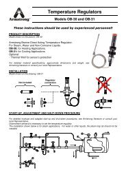
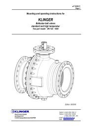
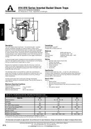
Anbau an Linearantrieb<br />
Mounting to linear actuator
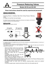
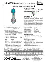
1. 3.<br />
4.<br />
2.<br />
Schrauben M5<br />
M5 screws<br />
Schrauben M6<br />
M6 screws<br />
Anbau an Schwenkantrieb<br />
Mounting to rotary actuator
Kurzanleitung<br />
Mechanischer Anbau<br />
siehe Klappseite<br />
Pneumatischer Anschluß<br />
• Hilfsenergie (Zuluft) im zulässigen Druckbereich<br />
(1,4...6 bar bzw. 20...90 psi) anschließen<br />
Achtung: max. Stelldruck des Stellantriebs beachten!<br />
• Antriebsversorgung an OUT1 (und OUT2 für doppeltwirkende<br />
Antriebe) anschließen<br />
Elektrische Anschlüsse<br />
• elektrische Anschlüsse wie folgt auflegen:<br />
+11/-12 Analogeingang, Sollwertstrom 4...20 mA<br />
+31/-32 Analogausgang, Stellungsrückmeldung 4...20 mA *<br />
+41/-42 Digitale Rückmeldung, unterer Schaltpunkt *<br />
+51/-52 Digitale Rückmeldung, oberer Schaltpunkt *<br />
+81/-82 Digitaler Schalteingang<br />
+83/-84 Digitaler Ausgang, Alarmkontakt<br />
+41/-42 Bausatz für digit. Rückmeldung, unterer Schaltpunkt *<br />
+51/-52 Bausatz für digit. Rückmeldung, oberer Schaltpunkt *<br />
* Option<br />
Lesen und beachten Sie die Sicherheitshinweise<br />
in Kapitel 1 dieser Betriebsanleitung.<br />
Brief operating instructions<br />
Mechanical mounting<br />
see fold-out drawing<br />
Pneumatic connection<br />
• Connect the air supply to the in port. Air supply range must<br />
be between 1.4 and 6 bar (20 to 90 psi). Caution: Do not<br />
exceed the max. pressure of the actuator!<br />
• Connect the actuator supply to the OUT1 port (and OUT2<br />
port for double acting actuators).<br />
Electrical connection<br />
• Make the electrical connections according to the following<br />
terminal designation:<br />
* Option<br />
Read and observe the safety instructions in<br />
chapter 1 of these operating instructions.<br />
+11/-12 Analog input, 4...20 mA signal<br />
+31/-32 Analog output, position feedback, 4...20 mA signal*<br />
+41/-42 Digital position feedback, low alarm output*<br />
+51/-52 Digital position feedback, high alarm output*<br />
+81/-82 Digital input<br />
+83/-84 Digital output, alarm contact<br />
+41/-42 Kit for digital position feedback, low alarm output*<br />
+51/-52 Kit for digital feedback, high alarm output*<br />
a
Inbetriebnahme<br />
1. pneumatische Hilfsenergie einspeisen<br />
2. Sollwertstrom 4...20 mA am Analogeingang einspeisen<br />
3. Anbau kontrollieren, hierzu<br />
- MODE drücken und halten<br />
- zusätzlich so lange oder drücken, bis Betriebsart<br />
1.3 (Handverstellung im Sensorbereich) angezeigt wird<br />
- MODE loslassen<br />
- oder drücken, um den Antrieb in die mechanischen<br />
Endlagen zu fahren, und Endlagen prüfen;<br />
angezeigt wird der Drehwinkel in Grad.<br />
Empfohlene Werte für die Endlagen:<br />
> -28° und < +28° für Linearantriebe<br />
> -57° und < +57° für Schwenkantriebe<br />
4. in die Konfigurationsebene wechseln, hierzu<br />
- und gleichzeitig drücken und halten<br />
- zusätzlich kurz ENTER drücken<br />
- Countdown von 3 auf 0 abwarten<br />
- und loslassen<br />
Parameter 1.0 in Parametergruppe P1._ wird automatisch<br />
aufgerufen.<br />
5. Antriebsart festlegen (Parameter 1.0), hierzu mit oder<br />
ROTARY oder LINEAR auswählen<br />
Diesen Schritt unbedingt vor dem Selbstabgleich<br />
(Schritt 6) durchführen.<br />
Commissioning<br />
1. Turn on the air supply to the positioner.<br />
2. Apply the 4...20 mA analog input signal to the positioner.<br />
3. Check for proper mounting:<br />
- Press and hold MODE.<br />
- Additionally briefly press or until mode 1.3<br />
(manual adjustment within the sensor range) is displayed.<br />
- Release MODE.<br />
- Press or to move the actuator to its mechanical<br />
limit stops in both directions, and note the values. The<br />
angle of rotation is indicated in degrees.<br />
Recommended positions of limit stops:<br />
> -28° and < +28° for linear actuators<br />
> -57° and < +57° for rotary actuators<br />
4. Switch to the configuration level:<br />
- Press and hold and simultaneously<br />
- Additionally briefly press ENTER<br />
- Wait until the countdown from 3 to 0 is completed.<br />
- Release and .<br />
The device will automatically go to parameter group P1._<br />
5. Select the actuator type (parameter P1); select ROTARY<br />
or LINEAR using or .<br />
This step must be performed prior to<br />
Autoadjust (step 6)<br />
b
6. Selbstabgleich starten, hierzu<br />
- MODE drücken und halten<br />
- zusätzlich kurz drücken, bis die Anzeige "P1.1"<br />
erscheint<br />
- MODE loslassen<br />
- ENTER drücken und bis zum Ablauf des Countdowns<br />
halten<br />
- ENTER loslassen<br />
Selbstabgleich wird gestartet.<br />
- Wenn mit "COMPLETE" ein erfolgreicher Selbstabgleich<br />
angezeigt wird, kurz mit ENTER bestätigen.<br />
Der Selbstabgleich kann auch mit einer Fehlermeldung<br />
abgebrochen werden. Siehe "P1.1 Selbstabgleich" auf<br />
Seite 64.<br />
7. Bei kritischen (z.B. sehr kleinen) Antrieben ggf. Toleranzband<br />
einstellen. Siehe hierzu "P1.2 Toleranzband" auf<br />
Seite 68. Normalerweise ist dieser Schritt nicht nötig.<br />
8. Ggf. die Einstellungen testen. Siehe hierzu "P1.3 Test" auf<br />
Seite 69.<br />
9. Einstellungen speichern, hierzu:<br />
- MODE drücken und halten<br />
- zusätzlich kurz drücken, bis "P1.4" erscheint<br />
- MODE loslassen<br />
- mit oder den Parameter auf NV-SAVE setzen<br />
- ENTER drücken und bis zum Ablauf des Countdowns<br />
halten, dann ENTER loslassen<br />
Die Einstellungen werden netzausfallsicher gespeichert.<br />
Das Gerät kehrt in die Arbeitsebene zurück. Die letzte<br />
aktive Betriebsart wird wieder aktiviert.<br />
6. Start Autoadjust:<br />
- Press and hold MODE.<br />
- Additionally briefly press ; until "P1.1" is indicated.<br />
- Release MODE.<br />
- Press ENTER and keep it pressed until the countdown<br />
is finished.<br />
- Release ENTER.<br />
Autoadjust is started.<br />
- If the message "COMPLETE" is displayed to indicate<br />
successful Autoadjust, briefly press ENTER to<br />
acknowledge.<br />
It is also possible that Autoadjust is automatically cancelled<br />
due to troubles, and an error message is displayed.<br />
See “P 1.1 Autoadjust” on page 64 for details.<br />
7. Adjust the tolerance band (only necessary for critical actuators,<br />
e.g. especially small ones). See “P1.2 Tolerance<br />
band” on page 68. Usually, this step is not required.<br />
8. If required test the settings. See “P1.3 Test” on page 69 for<br />
details.<br />
9. Save the settings:<br />
- Press and hold MODE<br />
- In addition, briefly press until P1.4 is indicated<br />
- Release MODE.<br />
- Select NV-SAVE using or .<br />
- Press and hold ENTER until the countdown is<br />
completed, then release ENTER.<br />
The settings are saved in the non-volatile memory, and the<br />
positioner returns to the operating level. The last previous<br />
operating mode is activated again.<br />
c
Betriebsart wählen<br />
Betriebsart 1.0: Regelung mit Adaption<br />
• MODE drücken und halten<br />
• zusätzlich so oft wie nötig kurz drücken<br />
• wird angezeigt<br />
conf<br />
% ° C<br />
mA<br />
• MODE loslassen<br />
• erscheint, Regelung mit Adaption läuft<br />
conf<br />
% ° C<br />
mA<br />
Betriebsart 1.1: Regelung ohne Adaption<br />
• MODE drücken und halten<br />
• zusätzlich so oft wie nötig kurz drücken<br />
• wird angezeigt<br />
conf<br />
% ° C<br />
mA<br />
• MODE loslassen<br />
Selecting operating mode<br />
Mode 1.0: Adaptive control<br />
• Press and hold MODE.<br />
% ° C<br />
mA<br />
conf<br />
• Release MODE.<br />
% ° C<br />
mA<br />
conf<br />
Mode 1.0: Fixed control<br />
• Press and hold MODE.<br />
% ° C<br />
mA<br />
conf<br />
• Release MODE.<br />
°<br />
% C<br />
mA<br />
• erscheint, Regelung ohne Adaption läuft<br />
• Additionally briefly press as often as required.<br />
• is displayed<br />
• is displayed, adaptive control is running.<br />
• Additionally briefly press as often as required.<br />
• is displayed<br />
% ° C<br />
mA<br />
• is displayed, fixed control is running.<br />
conf<br />
conf<br />
d
Mode 1.2: Manual adjustment within the stroke range<br />
Betriebsart 1.2: Handverstellung im Hubbereich<br />
•<br />
% C<br />
% C<br />
mA<br />
mA<br />
erscheint<br />
• is displayed.<br />
• MODE drücken und halten<br />
• Press and hold MODE.<br />
• zusätzlich so oft wie nötig kurz drücken<br />
• Additionally briefly press as often as required.<br />
•<br />
% C<br />
% C<br />
mA<br />
mA<br />
wird angezeigt<br />
• is displayed<br />
conf<br />
conf<br />
• MODE loslassen<br />
• Release MODE.<br />
•<br />
% C<br />
% C<br />
mA<br />
mA<br />
erscheint<br />
• is displayed.<br />
conf<br />
conf<br />
• Mit und Position im Hubbereich einstellen<br />
• Press or to adjust the position within the stroke range.<br />
Betriebsart 1.3: Handverstellung im Sensorbereich<br />
Mode 1.3: Manual adjustment within the sensor range<br />
• MODE drücken und halten<br />
• Press and hold MODE.<br />
• zusätzlich so oft wie nötig kurz drücken<br />
• Additionally briefly press as often as required.<br />
•<br />
% C<br />
% C<br />
mA<br />
mA<br />
wird angezeigt<br />
• is displayed<br />
conf<br />
conf<br />
• MODE loslassen<br />
• Release MODE.<br />
conf<br />
• Mit und Position im Sensorbereich einstellen<br />
Siehe Appendix A für Überblick über Konfigurationsebene.<br />
conf<br />
• Press or to adjust the position within the sensor<br />
range.<br />
See Appendix A for an overview on the configuration level.<br />
e
Beispiel für Parametereinstellung:<br />
"Kennlinienverlauf von steigend auf fallend ändern"<br />
Ausgangssituation: der <strong>TZID</strong>-C befindet sich in der Arbeitsebene<br />
in einer beliebigen Betriebsart.<br />
1. in die Konfigurationsebene wechseln, hierzu<br />
- und gleichzeitig drücken und halten<br />
- zusätzlich kurz ENTER drücken<br />
- Countdown von 3 auf 0 abwarten<br />
- ENTER loslassen<br />
- erscheint<br />
conf<br />
% ° C<br />
mA<br />
2. In Parametergruppe 2._ (siehe "Parametergruppe 2: Sollwert"<br />
auf Seite 71) wechseln, hierzu<br />
- MODE und ENTER gleichzeitig drücken und halten<br />
- zusätzlich einmal kurz drücken<br />
- erscheint<br />
conf<br />
% ° C<br />
mA<br />
- MODE und ENTER loslassen<br />
% C<br />
mA<br />
- erscheint<br />
"Changing valve action from direct to reverse"<br />
Starting situation: the <strong>TZID</strong>-C is operating on the operating<br />
level in an arbitrary mode<br />
1. Change over to the configuration level:<br />
- Simultaneously press and hold and .<br />
- In addition, briefly press ENTER.<br />
- Wait until countdown from 3 to 0 has run down.<br />
Parameter setting example:<br />
- Release ENTER.<br />
% ° C<br />
mA<br />
conf<br />
% ° C<br />
mA<br />
conf<br />
°<br />
- is displayed.<br />
2. Change over to parameter group 2._ (See “Parameter<br />
group 2: Setpoint” on page 71):<br />
- Simultaneously press and hold MODE and ENTER.<br />
- In addition briefly press once.<br />
- is displayed.<br />
- Release MODE and ENTER.<br />
% ° C<br />
mA<br />
- is displayed.<br />
conf<br />
conf<br />
f
3. Select parameter 2.3 "Valve action":<br />
3. Parameter 2.3 "Kennlinienverlauf" auswählen, hierzu<br />
-<br />
% C<br />
% C<br />
mA<br />
mA<br />
erscheint<br />
- is displayed.<br />
- MODE drücken und halten<br />
- Press and hold MODE.<br />
- zusätzlich 3 x kurz drücken<br />
- In addition, 3 x briefly press .<br />
-<br />
% C<br />
% C<br />
mA<br />
mA<br />
erscheint<br />
- is displayed.<br />
conf<br />
conf<br />
- MODE loslassen<br />
- Release MODE.<br />
4. Parametereinstellung ändern<br />
4. Change parameter setting:<br />
- Kurz drücken, um "REVERSE" (fallend)<br />
- Briefly press to select "REVERSE"<br />
auszuwählen.<br />
5. zu Parameter 2.7 "EXIT" wechseln und die Einstellungen<br />
speichern, hierzu:<br />
5. Change over to parameter 2.7 "EXIT" and save the new<br />
setting:<br />
- MODE drücken und halten<br />
- Press and hold MODE.<br />
- zusätzlich 4 x kurz drücken<br />
- In addition, 4 x briefly press .<br />
conf<br />
- MODE loslassen<br />
- Kurz drücken, um "NV_SAVE" (netzausfallsicher<br />
speichern) auszuwählen.<br />
- ENTER drücken und halten, bis der angezeigte<br />
Countdown von 3 auf 0 abgelaufen ist<br />
Das Gerät speichert die neue Einstellung und kehrt automatisch<br />
zurück in die Arbeitsebene.<br />
conf<br />
- Release MODE.<br />
- Briefly press to select "NV_SAVE"<br />
- Press and hold ENTER until the displayed countdown<br />
from 3 to 0 has run down.<br />
The positioner saves the new setting and automatically returns<br />
to the operating level.<br />
g
Inhaltsverzeichnis<br />
Table of Contents<br />
Kurzanleitung ........................................................ a<br />
1 Hinweise zu Ihrer Sicherheit ........................... 1<br />
1.1 Allgemeines .......................................................... 1<br />
1.2 Symbol- und Hinweiserklärung ........................... 2<br />
1.3 Hinweise zur elektrischen und<br />
pneumatischen Sicherheit .................................. 3<br />
1.4 Bestimmungsgemäßer Gebrauch ....................... 3<br />
1.5 Qualifiziertes Personal.......................................... 4<br />
2 Herstellerangaben ............................................ 5<br />
2.1 Lieferung ............................................................... 5<br />
2.2 Konformitätserklärung......................................... 5<br />
3 Anwendung und Kurzbeschreibung .............. 6<br />
4 Installieren und Inbetriebnehmen ................ 12<br />
4.1 Mechanischer Anbau ......................................... 12<br />
4.1.1 Allgemeines.............................................. 12<br />
4.1.2 Betriebsbedingungen am Installationsort 13<br />
Brief operating instructions ..................................... a<br />
1 Safety and precautions ........................................ 1<br />
1.1 General .................................................................. 1<br />
1.2 Explanation of warning signs and notes ............ 2<br />
1.3 Notes on electrical and<br />
pneumatic safety .................................................. 3<br />
1.4 Proper use.............................................................. 3<br />
1.5 Qualified personnel .............................................. 4<br />
2 Manufacturer’s information ................................. 5<br />
2.1 Delivery .................................................................. 5<br />
2.2 CE compliance information ................................. 5<br />
3 Application and brief description ....................... 6<br />
4 Installing and commissioning ........................... 12<br />
4.1 Mechanical mounting ......................................... 12<br />
4.1.1 General...................................................... 12<br />
4.1.2 Operating conditions at the installation site13<br />
i
4.1.3 Anbau an Linearantrieb ............................ 14<br />
4.1.4 Anbau an Schwenkantrieb ........................ 20<br />
4.1.5 Anbau an Regelventile 23/24, 23/25<br />
und 23/26 .................................................. 23<br />
4.2 Pneumatischer Anschluß .................................. 25<br />
4.3 Elektrischer Anschluß........................................ 27<br />
4.4 Inbetriebnahme ................................................... 30<br />
4.4.1 Anbau kontrollieren ................................... 30<br />
4.4.2 Antriebsart festlegen................................. 32<br />
4.4.3 Selbstabgleich durchführen...................... 32<br />
4.4.4 Toleranzband einstellen ........................... 33<br />
4.4.5 Einstellungen testen ................................. 34<br />
4.4.6 Einstellungen speichern ........................... 34<br />
5 Nachträglicher Einbau von Optionen ........... 35<br />
5.1 Mechanische Stellungsanzeige ......................... 35<br />
5.2 Steckmodul für analoge Rückmeldung ............ 36<br />
5.3 Steckmodul für digitale Rückmeldung............. 38<br />
5.4 Mechanischer Bausatz für digitale<br />
Rückmeldung ..................................................... 40<br />
5.5 Manometerblock und Filterregler...................... 43<br />
4.1.3 Mounting to linear actuator ....................... 14<br />
4.1.4 Mounting to rotary actuator ....................... 20<br />
4.1.5 Mounting to control valves 23/24,<br />
23/25 and 23/26 ........................................ 23<br />
4.2 Pneumatic connection ....................................... 25<br />
4.3 Electrical connection ......................................... 27<br />
4.4 Commissioning ................................................... 30<br />
4.4.1 Checking the mounting............................. 30<br />
4.4.2 Determining the actuator type .................. 32<br />
4.4.3 Running Autoadjust .................................. 32<br />
4.4.4 Setting the tolerance band ........................ 33<br />
4.4.5 Testing the settings .................................. 34<br />
4.4.6 Saving the settings ................................... 34<br />
5 Installation of option cards ................................35<br />
5.1 Mechanical position indicator ........................... 35<br />
5.2 Plug-in module for analog position feedback... 36<br />
5.3 Plug-in module for digital position feedback .. 38<br />
5.4 Mechanical kit for digital position feedback ... 40<br />
5.5 Pressure gage block and filter regulator .......... 43<br />
ii
5.6 Auswechseln des I/P-Moduls ............................ 44<br />
6 Lokale Bedienung .......................................... 49<br />
6.1 Allgemeines ........................................................ 49<br />
6.2 Bedienelemente .................................................. 50<br />
6.2.1 Beschreibung ............................................ 50<br />
6.2.2 Arbeiten mit den Bedienelementen .......... 53<br />
6.3 Bediensperre ....................................................... 58<br />
6.4 Betrieb in der Arbeitsebene ............................... 59<br />
6.5 Parametrierung ................................................... 63<br />
7 Wartung ........................................................ 111<br />
7.1 Luftfilter im <strong>Stellungsregler</strong> kontrollieren ...... 112<br />
7.2 Filterregler überprüfen ..................................... 113<br />
7.3 Funktionsprüfung/Nachjustierung .................. 113<br />
8 Technische Daten ........................................ 114<br />
8.1 Grundgerät ........................................................ 114<br />
8.2 Optionen ............................................................ 118<br />
8.3 Zubehör ............................................................. 119<br />
9 Maßbilder ..................................................... 121<br />
5.6 Replacing the I/P module ................................... 44<br />
6 Local operation .................................................. 49<br />
6.1 General ................................................................ 49<br />
6.2 Operating elements ............................................ 50<br />
6.2.1 Description ................................................ 50<br />
6.2.2 Using the operating elements ................... 53<br />
6.3 Inhibiting operation ............................................ 58<br />
6.4 Operation on the operating level ...................... 59<br />
6.5 Setting parameters ............................................. 63<br />
7 Maintenance ..................................................... 111<br />
7.1 Checking the air filter in the positioner .......... 112<br />
7.2 Checking the filter regulator ............................ 113<br />
7.3 Functional test/re-adjustment ......................... 113<br />
8 Technical data .................................................. 114<br />
8.1 Basic model ...................................................... 114<br />
8.2 Options .............................................................. 118<br />
8.3 Accessories ...................................................... 119<br />
9 Dimensional drawings ..................................... 121<br />
iii
10 Fehlercodes, Alarme, Meldungen ............... 125<br />
10.1 Fehlercodes ...................................................... 125<br />
10.2 Alarme ............................................................... 129<br />
10.3 Meldungen ......................................................... 132<br />
Appendix<br />
10 Error codes, alarms, messages ......................125<br />
10.1 Error codes ....................................................... 125<br />
10.2 Alarms ............................................................... 129<br />
10.3 Messages .......................................................... 132<br />
Appendix<br />
iv
1 Hinweise zu Ihrer Sicherheit<br />
1.1 Allgemeines<br />
Dieses Kapitel enthält wichtige Hinweise zu<br />
Ihrer Sicherheit. Lesen Sie diese Hinweise<br />
sorgfältig und beachten Sie sie.<br />
Der einwandfreie und sichere Betrieb des <strong>Stellungsregler</strong>s<br />
<strong>TZID</strong>-C setzt folgendes voraus:<br />
• sachgemäße(n) Transport und Lagerung<br />
• fachgerechte Installation und Inbetriebnahme<br />
• Bedienung gemäß der in dieser Betriebsanleitung<br />
gegebenen Anweisungen<br />
• bestimmungsgemäßen Gebrauch (siehe Kapitel 1.4,<br />
Seite 3)<br />
• sorgfältige Instandhaltung<br />
An dem Gerät darf nur qualifiziertes Personal arbeiten<br />
(siehe Kapitel 1.5, Seite 4).<br />
Beachten Sie<br />
• den Inhalt dieser Betriebsanleitung<br />
• die einschlägigen Sicherheitsvorschriften für die<br />
Errichtung und den Betrieb elektrischer Anlagen<br />
• die Verordnungen und Richtlinien über den Explosionsschutz,<br />
sofern explosionsgeschützte Geräte<br />
zum Einsatz kommen<br />
Die in dieser Betriebsanleitung genannten Verordnungen,<br />
Normen und Richtlinien gelten in Deutschland. Bei<br />
Einsatz des <strong>Stellungsregler</strong>s <strong>TZID</strong>-C in anderen Ländern<br />
sind die einschlägigen nationalen Regeln zu<br />
beachten.<br />
1 Safety and precautions<br />
1.1 General<br />
Proper and safe operation of the <strong>TZID</strong>-C positioner<br />
requires<br />
• proper transportation and storage<br />
• installation and commissioning by qualified<br />
personnel<br />
• correct operation according to the instructions in this<br />
manual<br />
• proper use (see chapter 1.4 on page 3)<br />
• careful maintenance<br />
Only qualified personnel are allowed to work on the<br />
device (see chapter 1.5 on page 4).<br />
Observe<br />
Important instructions for your safety!<br />
Read and observe!<br />
• the present operating instructions<br />
• the relevant safety regulations and standards for the<br />
installation and operation of electrical systems<br />
• the standards, regulations and directives governing<br />
explosion protection, when using intrinsically safe<br />
devices<br />
The regulations, standards and directives referred to in<br />
these operating instructions are applicable in Germany.<br />
When using the <strong>TZID</strong>-C positioner outside the German<br />
Federal jurisdiction, the relevant regulations, standards<br />
and directives applicable in the country where the device<br />
is used must be observed.<br />
1
Der <strong>Stellungsregler</strong> <strong>TZID</strong>-C ist gemäß DIN VDE 0411<br />
Teil 1<br />
Schutzmaßnahmen für elektronische Meßgeräte<br />
gebaut und geprüft worden und hat das Werk in sicherheitstechnisch<br />
einwandfreiem Zustand verlassen.<br />
Um diesen Zustand zu erhalten und einen gefahrlosen<br />
Betrieb sicherzustellen, sind die in dieser Betriebsanleitung<br />
mit Symbolen (siehe Kapitel 1.2) markierten Gefahrenhinweise<br />
und Sicherheitshinweise sorgfältig zu lesen<br />
und genau zu beachten. Andernfalls können Personen<br />
gefährdet und das Gerät selbst sowie andere Geräte<br />
und Einrichtungen beschädigt werden bzw. ausfallen.<br />
1.2 Symbol- und Hinweiserklärung<br />
Wichtige Informationen sind in dieser Betriebsanleitung<br />
durch folgende Symbole gekennzeichnet und hervorgehoben:<br />
Gefahr<br />
Dieses Symbol kennzeichnet einen Gefahrenhinweis.<br />
Werden die hier gegebenen Anweisungen<br />
nicht befolgt, besteht Gefahr für das<br />
Leben oder die Gesundheit von Personen<br />
und/oder es kann erheblicher Sachschaden<br />
eintreten.<br />
The <strong>TZID</strong>-C positioner has been designed and tested in<br />
accordance with DIN VDE 0411 Part 1<br />
Safety Requirements for Electronic Measuring<br />
Apparatuses<br />
(based on IEC Publication 348) and has been supplied<br />
in a safe condition.<br />
The present operating instructions contain warnings and<br />
cautions marked with a symbol (see chapter 1.2). The<br />
instructions given in these sections must be observed to<br />
retain the device in a safe condition and to ensure safe<br />
operation. Otherwise, persons can be endangered or the<br />
device itself or other devices or equipment may be damaged<br />
or fail.<br />
1.2 Explanation of warning signs and notes<br />
Important information has been marked and emphasized<br />
with the following symbols in these operating<br />
instructions:<br />
Warning<br />
This symbol is printed next to warnings<br />
indicating a direct endangerment of a<br />
person’s health or life.<br />
Also, major property damages may occur.<br />
Werden die mit diesem Symbol gekennzeichneten<br />
Sicherheitshinweise nicht befolgt, kann<br />
es zu leichteren Körperverletzungen und<br />
Sachschaden kommen.<br />
Dieses Symbol kennzeichnet Hinweise, die<br />
wichtige Informationen zu Ihrem <strong>TZID</strong>-C und<br />
seiner Handhabung enthalten.<br />
Caution<br />
If the safety notes marked with this symbol are<br />
not observed, minor personal injuries and<br />
property damages may result.<br />
This symbol is printed next to notes containing<br />
important informationen pertaining to your<br />
<strong>TZID</strong>-C or its operation.<br />
2
1.3 Hinweise zur elektrischen und<br />
pneumatischen Sicherheit<br />
1.3 Notes on electrical and<br />
pneumatic safety<br />
Gefahr<br />
• Nur qualifiziertes Fachpersonal darf den<br />
<strong>Stellungsregler</strong> <strong>TZID</strong>-C montieren, elektrisch<br />
und pneumatisch anschließen und in<br />
Betrieb nehmen.<br />
• Stellen Sie die elektrische Sicherheit der<br />
speisenden Geräte sicher.<br />
• Beachten Sie bei der elektrischen Verdrahtung<br />
die Werte gemäß Kapitel 8 "Technische<br />
Daten".<br />
• Beachten Sie für die elektrische Installation<br />
von Ex-geschützten Geräten die nationalen<br />
Rechtsverordnungen, die DIN/VDE-Bestimmungen,<br />
insbesondere VDE 0165, die<br />
Richtlinien für den Explosionsschutz und<br />
den Ex-Prüfschein des Geräts.<br />
• Beachten Sie bei der Montage und Inbetriebnahme<br />
die Sicherheitsvorschriften der<br />
pneumatischen Antriebe. Es besteht Verletzungsgefahr<br />
durch die hohen Stellkräfte der<br />
Antriebe.<br />
Danger<br />
• Only qualified persons may mount, electrically<br />
and pneumatically connect, and commission<br />
the <strong>TZID</strong>-C positioner.<br />
• Ensure the electrical safety of all feeding<br />
devices.<br />
• When connecting the electrical wiring,<br />
observe the specifications according to<br />
chapter 8 "Technical data".<br />
• For the electrical installation of ex-protected<br />
devices, observe all national regulations,<br />
DIN/VDE directives, especially VDE 0165,<br />
the directives for explosion protection, and<br />
the ex-certificate of the device.<br />
• Observe the safety instructions of the pneumatic<br />
actuators when mounting and commissioning<br />
the devices. There is danger of<br />
injuries due to the high displacement forces<br />
of the actuators.<br />
1.4 Bestimmungsgemäßer Gebrauch<br />
Der <strong>TZID</strong>-C ist ein elektropneumatischer <strong>Stellungsregler</strong><br />
zum Anbau an pneumatische Linear- und Schwenkantriebe.<br />
Das Gerät darf nur für die in dieser Betriebsanleitung<br />
bzw. im technischen Listenblatt 18-0.22 beschriebenen<br />
Anwendungsfälle eingesetzt werden.<br />
1.4 Proper use<br />
The <strong>TZID</strong>-C positioner is an electro-pneumatic valve<br />
positioner for use with pneumatic linear and rotary actuators.<br />
The device may only be used for the applications listed<br />
in these operating instructions and in the data sheet<br />
18-0.22 EN.<br />
3
1.5 Qualifiziertes Personal<br />
An dem Gerät dürfen nur Personen arbeiten, die mit der<br />
Installation, Inbetriebnahme, Bedienung und Instandhaltung<br />
des <strong>Stellungsregler</strong>s <strong>TZID</strong>-C oder vergleichbarer<br />
Geräte vertraut sind und über die für ihre Tätigkeit erforderliche<br />
Qualifikation verfügen.<br />
Im Einzelnen sind dies:<br />
• Projektierungsfachleute, die mit den Sicherheitskonzepten<br />
der Automatisierungstechnik vertraut sind<br />
• Inbetriebnahme- bzw. Servicepersonal, d.h. Personen,<br />
die aufgrund einer entsprechenden Ausbildung<br />
befähigt sind, den <strong>Stellungsregler</strong> <strong>TZID</strong>-C oder vergleichbare<br />
Geräte der Automatisierungstechnik zu<br />
montieren, in Betrieb zu nehmen, zu reparieren und<br />
zu warten bzw. die berechtigt sind, Stromkreise und<br />
Geräte oder Systeme entsprechend der Standards<br />
und Richtlinien der Sicherheitstechnik in Betrieb zu<br />
nehmen, zu erden und zu kennzeichnen.<br />
• Bedienungspersonal, das den Umgang mit Einrichtungen<br />
der Automatisierungstechnik beherrscht und<br />
sich mit dem Inhalt dieser Betriebsanleitung, insbesondere<br />
mit den in Kapitel 6 "Lokale Bedienung" aufgeführten<br />
Hinweisen und Informationen, vertraut<br />
gemacht hat.<br />
1.5 Qualified personnel<br />
Only those persons familiar with the installation, commissioning,<br />
operation and maintenance of the <strong>TZID</strong>-C<br />
positioner or similar instruments and who have the<br />
required qualification are authorized to work on the<br />
device.<br />
These persons are:<br />
• Project specialists who are familiar with the security<br />
concepts of process automation.<br />
• Commissioning and service personnel, i. e. persons<br />
who have been trained adequately to mount, commission,<br />
repair, and maintain the <strong>TZID</strong>-C positioner<br />
or similar automation instruments or who are –<br />
according to safety standards and guidelines – permitted<br />
to commission, ground, and label electrical<br />
circuitry, devices, and systems.<br />
• Operating personnel who is familiar with handling<br />
automation equipment and with the contents of<br />
these operating instructions, especially the information<br />
and notes in chapter 6 "Lslot sensorocal operation".<br />
4
2 Herstellerangaben<br />
2.1 Lieferung<br />
Prüfen Sie die Ware unverzüglich bei Erhalt auf Vollständigkeit<br />
und Unversehrtheit. Der Lieferumfang geht aus<br />
den Versandpapieren hervor. Mitbestelltes Zubehör (z.B.<br />
Anbaumaterial, Manometerblock, Filterregler) liegt dem<br />
Gerät lose bei. Stellen Sie anhand der Bestellnummern<br />
fest, ob die Ware hinsichtlich der Ausführung und des<br />
Umfangs bestellgemäß geliefert wurde.<br />
Wenn der <strong>Stellungsregler</strong> an den Stellantrieb angebaut<br />
ausgeliefert wird, bilden <strong>Stellungsregler</strong>, Zubehör und<br />
Stellantrieb bzw. Stellglied eine gemeinsame Liefereinheit.<br />
Eine Auflistung der Bestellnummern sowie Einzelheiten<br />
zu den Liefervarianten und dem Zubehör finden Sie im<br />
technischen Listenblatt 18-0.22.<br />
2.2 Konformitätserklärung<br />
Wir erklären, daß wir Hersteller des <strong>Stellungsregler</strong>s<br />
<strong>TZID</strong>-C sind und daß das Gerät die Schutzanforderungen<br />
der EG-Richtlinie 89/336/EWG vom Mai 1989 aufgrund<br />
der Einhaltung folgender Normen erfüllt:<br />
Fachgrundnormen/Produktnormen<br />
Störaussendung EN 55022 vom Mai 1995<br />
EN 50081-1 vom März 1993<br />
Störfestigkeit EN 50082-1 vom März 1993<br />
Der <strong>Stellungsregler</strong> <strong>TZID</strong>-C erfüllt die EG-Richtlinie für<br />
die CE-Konformitätskennzeichnung.<br />
2 Manufacturer’s information<br />
2.1 Delivery<br />
When receiving the delivery please immediately check<br />
items and scope for damages and completeness. The<br />
scope of delivery is stated in the shipping documents. If<br />
ordered, the accessories (e.g. mounting material, pressure<br />
gauge block, filter regulator) are added to the delivery<br />
as individual items. Check items and scope of the<br />
delivery by means of the catalog numbers to see if types<br />
and quantities are in accordance with your order.<br />
If the positioner is delivered already mounted to the<br />
actuator, the positioner, accessories, and actuator are<br />
considered as a common delivery item<br />
A list of catalog numbers and details of the different versions<br />
and accessories can be found in the data sheet<br />
18-0.22 EN.<br />
2.2 CE compliance information<br />
We declare that we are the manufacturer of the <strong>TZID</strong>-C<br />
positioner and that the product conforms with the regulations<br />
listed below and meets the following requirements<br />
of EC regulation 89/336/CEE as of May 1989:<br />
Basic technical standards/product standards<br />
RFI suppression EN 55022 as of May 1995<br />
EN 50081-1 as of March 1993<br />
EMI/RFI shielding EN 50082-1 as of March 1993<br />
The <strong>TZID</strong>-C positioner meets the EC regulation for CE<br />
conformity.<br />
5
3 Anwendung und Kurzbeschreibung<br />
Der elektropneumatische <strong>Stellungsregler</strong> <strong>TZID</strong>-C ist<br />
konzipiert für den Anbau an einen pneumatischen Stellantrieb.<br />
Er kann sowohl an Linearantriebe (nach DIN/<br />
IEC 534) als auch an Schwenkantriebe (nach VDI/VDE<br />
3845) angebaut werden. Auch der integrierte Anbau an<br />
Regelventile 23/24, 23/25 und 23/26 ist möglich.<br />
Die Ansteuerung kann einfachwirkend (Rückstellung mit<br />
Feder) oder doppeltwirkend (beide Stellrichtungen mit<br />
pneumatischer Betätigung) erfolgen.<br />
Der Stelleingang ist in Zweileitertechnik ausgeführt. Die<br />
Versorgungsspannung wird aus dem 4...20 mA Eingangssignal<br />
generiert.<br />
Aufbau<br />
3 Application and brief description<br />
The <strong>TZID</strong>-C is an electro-pneumatic valve positioner. It<br />
can be mounted to either linear pneumatic actuators in<br />
accordance with DIN/IEC 534 or rotary pneumatic actuators<br />
according to VDI/VDE 3845. Special integral<br />
mounting to control valves 23/24, 23/25 and 23/26 is<br />
also possible.<br />
Actuation can be single-acting (spring return) or doubleacting<br />
(air to open and close).<br />
The positioner is a two-wire instrument. The supply voltage<br />
is derived from the 4...20 mA input signal.<br />
Construction<br />
6<br />
Abb.1<br />
Fig. 1<br />
<strong>Stellungsregler</strong> <strong>TZID</strong>-C, geschlossen<br />
<strong>TZID</strong>-C positioner, closed<br />
Abb.2<br />
Fig. 2<br />
<strong>Stellungsregler</strong> <strong>TZID</strong>-C, geöffnet<br />
<strong>TZID</strong>-C positioner, open
Abb. 1 und Abb. 2 zeigen einen voll bestückten <strong>TZID</strong>-C<br />
mit folgenden Erweiterungsoptionen:<br />
• Mechanische Stellungsanzeige (Spezialdeckel mit<br />
transparenter Kuppel, Symbolaufkleber zum Markieren<br />
der min. und max. Ventilstellung, Drehbalkenanzeige<br />
zum Aufstecken auf die Geräteachse)<br />
• Bausatz für digitale Rückmeldung (zwei Pepperl &<br />
Fuchs Schlitzinitiatoren mit Steuerfahnen zum Aufstecken<br />
auf die Geräteachse, nur zusammen mit<br />
mechanischer Stellungsanzeige einsetzbar)<br />
• Steckmodul für analoge Rückmeldung<br />
• Steckmodul für digitale Rückmeldung<br />
Funktionsprinzip<br />
Die Bewegung des Stellantriebs wird auf die Drehachse<br />
des <strong>Stellungsregler</strong>s <strong>TZID</strong>-C übertragen, mit einem<br />
Wegsensor erfaßt und in ein elektrisches Signal umgesetzt.<br />
Der Stelleingang (Sollwert der 4...20 mA Schleife)<br />
und die Stellposition (Istwert, vom Wegsensor) werden<br />
der Elektronik (CPU) über A/D-Wandler zugeführt. Der<br />
Mikroprozessor bildet daraus die Regelabweichung und<br />
berechnet anhand eines PD-Regelalgorithmus ein Stellsignal,<br />
mit dem über einen D/A-Wandler analog ein I/P-<br />
Modul angesteuert wird (siehe Abb. 3).<br />
Das I/P-Modul ist die pneumatische Ausgabeeinheit des<br />
<strong>Stellungsregler</strong>s. Es besteht aus einer Vorsteuerstufe<br />
und einem analogen 3/3-Wegeventil, das als Leistungsstufe<br />
dient. Die Vorsteuerstufe setzt das elektrische<br />
Ansteuersignal über ein System elektromagnetische<br />
Spule/Festmagnet und Düse/Prallplatte in einen Vordruck<br />
um, mit dem die Leistungsstufe angesteuert wird.<br />
Fig. 1 and Fig. 2 shows a fully equipped <strong>TZID</strong>-C with the<br />
following options:<br />
• Mechanical position indicator (special cover with<br />
transparent dome, symbol sticker for marking the<br />
min. and max. valve positions, mechanical position<br />
indicator for mounting to the feedback shaft)<br />
• Kit for digital position feedback (2 Pepperl & Fuchs<br />
proximity switches with slot sensors for mounting<br />
onto the feedback shaft, only to be used in connection<br />
with the mechanical position indicator)<br />
• Plug-in module for analog position feedback<br />
• Plug-in module for digital position feedback<br />
Functional description<br />
The movement of the actuator is coupled to the feedback<br />
shaft of the <strong>TZID</strong>-C positioner, detected by a position<br />
sensor, and converted to an electrical signal. The<br />
input (position demand of the 4...20 mA canal) and the<br />
actual position are transferred to the electronics (CPU)<br />
via an A/D converter. Using these values the microprocessor<br />
calculates the control deviation and – through a<br />
P/D control algorithm – a positioning signal that is used<br />
to activate an I/P module via an A/D converter (see Fig.<br />
3).<br />
The I/P module is the pneumatic output unit of the positioner.<br />
It consists of a pilot stage and an analog 3/3-way<br />
valve that is used as the booster stage. The pilot stage<br />
converts the electrical signal – via a system of coil/magnet<br />
and nozzle/flapper – into a supply pressure that<br />
actuates the power stage.<br />
7
Abb.3<br />
Fig. 3<br />
Übersicht über Baugruppen und Anschlüsse des <strong>Stellungsregler</strong>s <strong>TZID</strong>-C<br />
Overview of <strong>TZID</strong>-C assembly groups and connectors<br />
8
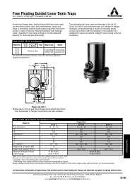
Wegbereich des <strong>Stellungsregler</strong>s<br />
Der <strong>Stellungsregler</strong> <strong>TZID</strong>-C kann an seiner Antriebsachse<br />
einen Drehwinkel von 60 Grad bei Linearantrieben<br />
und 120 Grad bei Schwenkantrieben erfassen.<br />
Dabei unterscheidet man drei Bereiche (siehe Abb. 4):<br />
• Sensorbereich<br />
• Ventilbereich<br />
• Hubbereich<br />
<strong>Positioner</strong> range<br />
The <strong>TZID</strong>-C positioner can detect an angle of rotation of<br />
60 degrees for linear actuators and of 120 degrees for<br />
rotary actuators. There are three different ranges (see<br />
Fig. 4):<br />
• Sensor range<br />
• Valve range<br />
• Stroke range<br />
+30°<br />
Sensorbereich für Linearantriebe<br />
Sensor range for linear actuators<br />
+60°<br />
Sensorbereich für Schwenkantriebe<br />
Sensor range for rotary actuators<br />
100%<br />
100%<br />
0%<br />
-30°<br />
0%<br />
-60°<br />
Ventilbereich<br />
Valve range<br />
Hubbereich<br />
Stroke range<br />
Abb.4<br />
Fig. 4<br />
Wegbereich des <strong>Stellungsregler</strong>s<br />
<strong>Positioner</strong> range<br />
9
10<br />
Der Sensorbereich ist der maximale Bereich, in dem<br />
die Bewegung der Drehachse gemessen werden kann.<br />
Der Ventilbereich ist der maximale Bereich, in dem der<br />
<strong>TZID</strong>-C ein angebautes Ventil verfahren kann. Die Grenzen<br />
des Ventilbereichs hängen von dem Ventil und von<br />
dem jeweiligen mechanischen Anbau ab. Sie werden in<br />
der Regel durch den Selbstabgleich ermittelt, können<br />
aber auch durch lokale oder externe Parametrierung<br />
bestimmt werden.<br />
Der Hubbereich ist der vom Anwender definierte<br />
Bereich innerhalb des Ventilbereichs, der den Verfahrweg<br />
des Ventils begrenzt. Er wird angegeben in % bezogen<br />
auf den Ventilbereich. Wird der Ventilbereich neu<br />
bestimmt (z.B. durch Selbstabgleich), wird der Hubbereich<br />
für den neuen Ventilbereich entsprechend neu<br />
berechnet. Die für den Hubbereich eingestellte Zahl in %<br />
bleibt dabei erhalten. Der Sollwertbereich bezieht sich<br />
immer auf den Hubbereich.<br />
HART ® -Kommunikation<br />
Der <strong>Stellungsregler</strong> <strong>TZID</strong>-C besitzt einen Kommunikationsanschluß,<br />
über den er von einem PC aus bedient,<br />
beobachtet und parametriert werden kann. Die Kommunikation<br />
erfolgt über einen LKS-Adapter oder ein FSK-<br />
Modem auf der Basis des HART ® -Protokolls. Die folgende<br />
Ausstattung ist für die Kommunikation erforderlich<br />
(siehe Abb. 5 und Abb. 6):<br />
• LKS-Adapter oder FSK-Modem<br />
• PC<br />
• Parametrierprogramm IBIS oder Smart Vision ®<br />
Weitere Informationen hierzu finden Sie in dem separaten<br />
Benutzerhandbuch für IBIS bzw. Smart Vision ® .<br />
The sensor range is the maximum range in which the<br />
movement of the rotary feedback shaft can be measured.<br />
The valve range is the maximum range in which the<br />
<strong>TZID</strong>-C positioner can position an attached valve. The<br />
limits of the valve range depend on the valve and the<br />
respective mechanical mounting. Normally the limits are<br />
determined by Autoadjust but can also be determined by<br />
local or external parameter settings.<br />
The stroke range is the user-defined range that limits<br />
the valve travel within the valve range. The stroke range<br />
value is stated as a percentage of the valve range. If a<br />
new valve range is determined (e.g. by Autoadjust), the<br />
stroke range is recalculated according to the new valve<br />
range. The percent value set for the stroke range is<br />
maintained. The setpoint range always relates to the<br />
stroke range.<br />
HART ® communication<br />
The <strong>TZID</strong>-C positioner contains a communication connection<br />
that enables the positioner to be operated, monitored,<br />
and configured via a PC. The communication is<br />
executed via an LKS adapter or an FSK modem and<br />
based on the HART ® protocol. The following equipment<br />
is required for communication (see Fig. 5 and Fig. 6):<br />
• LKS adapter or FSK modem<br />
• PC<br />
• Configuration software IBIS or Smart Vision ®<br />
For further information consult the separate user manuals<br />
for IBIS and Smart Vision ® .
Abb.5<br />
Fig. 5<br />
Kommunikation über LKS-Adapter<br />
Communication via LKS adapter<br />
Abb.6<br />
Fig. 6<br />
Kommunikation über FSK-Modem<br />
Communication via FSK modem<br />
11
4 Installieren und Inbetriebnehmen<br />
4.1 Mechanischer Anbau<br />
4.1.1 Allgemeines<br />
Diese Betriebsanleitung beschreibt ausschließlich die<br />
Montage an Linearantriebe nach DIN/IEC 534 (seitlicher<br />
Anbau nach Namur), an Schwenkantriebe nach VDI/<br />
VDE 3845 und an Ventile 23/24, 23/25 und 23/26. Für<br />
den antriebsspezifischen Anbau sind separate Montageanleitungen<br />
erhältlich.<br />
4 Installing and commissioning<br />
4.1 Mechanical mounting<br />
4.1.1 General<br />
These operating instructions explain the mounting to linear<br />
actuators according to DIN/IEC 534 (lateral attachment<br />
according to Namur), to rotary actuators according<br />
to VDI/VDE 3845, and to control valves 23/24, 23/25 and<br />
23/26. Instructions for special actuator-specific attachment<br />
are available separately.<br />
Achten Sie bei der Montage<br />
auf die richtige Umsetzung<br />
des Stellwegs bzw. des<br />
Drehwinkels für die Stellungsrückmeldung.<br />
Der<br />
maximale Drehwinkelbereich<br />
für die Stellungsrückmeldung<br />
beträgt beim<br />
Anbau an Linearantriebe<br />
60° und beim Anbau an<br />
Schwenkantriebe 120°<br />
(siehe Abb. 4 auf Seite 9).<br />
Der Pfeil (1) an der Geräteachse<br />
(und damit der<br />
Hebel) muß sich innerhalb<br />
des durch die kleinen<br />
Pfeile begrenzten<br />
Bereichs (2) bewegen<br />
(siehe Abb. 7).<br />
Wenn Sie einen möglichst<br />
großen Bereich ausnutzen<br />
wollen, sollte der Hebel bei<br />
Abb.7<br />
Fig. 7<br />
1 2<br />
Arbeitsbereich<br />
Operating range<br />
When mounting, ensure that<br />
the transfer of the stroke or<br />
rotation angle for the position<br />
feedback is correct. The maximum<br />
rotation angle is 60° for<br />
mounting to linear actuators<br />
and 120° for mounting to<br />
rotary actuators (see Fig. 4<br />
on page 9). The arrow (1) on<br />
the feedback shaft (and<br />
thus the lever) must travel<br />
within the area marked with<br />
the small arrows (2)<br />
(see Fig. 7).<br />
To enable you to use a big<br />
range, the lever should be<br />
positioned in the center<br />
between the arrows at half<br />
stroke (+ 0° sensor position).<br />
12
halbem Hub (+ 0 Sensorposition) mittig zwischen den<br />
Pfeilen stehen.<br />
Beim Anbau genügt eine grobe Einstellung des praktisch<br />
genutzten Drehwinkelbereichs. Die Feineinstellung<br />
erfolgt automatisch beim Selbstabgleich während der<br />
Inbetriebnahme.<br />
Der praktisch genutzte Drehwinkelbereich muß mindestens<br />
12° für Linearantriebe bzw. 24° für Schwenkantriebe<br />
betragen. Die Lage des Segments innerhalb des<br />
Bereichs ist dabei beliebig.<br />
4.1.2 Betriebsbedingungen am Installationsort<br />
Gefahr<br />
Umgebungstemperatur:<br />
Schutzanforderung: IP 65<br />
Schutzklasse:<br />
Einbaulage:<br />
Bei schwierigen Regelstrecken mit hoher<br />
Reibung oder kleiner Stellzeit ist es vorteilhaft,<br />
den tatsächlich genutzten Drehwinkelbereich<br />
möglichst groß anzulegen.<br />
Aus Sicherheitsgründen sollte der praktisch<br />
genutzte Drehwinkelbereich mindestens 2°<br />
(bei Linearantrieben) bzw. 3° (bei Schwenkantrieben)<br />
von den Endpunkten des Sensorbereichs<br />
entfernt bleiben.<br />
Prüfen Sie vor der Montage, ob der <strong>TZID</strong>-C<br />
die regel- und sicherheitstechnischen<br />
Anforderungen an der Einbaustelle<br />
(Stellantrieb bzw. Stellglied) erfüllt.<br />
-30...+85°C<br />
II 2G EEx ib II C T6<br />
beliebig<br />
During mounting, a rough adjustment of the actually<br />
used rotation angle range is sufficient. The fine adjustment<br />
is automatically performed during Autoadjust.<br />
The total rotational angle must be 12° minimum for linear<br />
actuators and 24° for rotary actuators. The position<br />
of the segment within the range is arbitrary.<br />
4.1.2 Operating conditions at the installation site<br />
Warning<br />
For difficult controlling tasks with high friction<br />
or short positioning times it is advantageous<br />
to provide a rotation angle range as<br />
wide as possible.<br />
For safety reasons the practically used rotation<br />
angle range should be kept at a minimum<br />
distance of 2° (for linear actuators) or<br />
3° (for rotary actuators) from the final positions<br />
of the sensor range.<br />
Before installing check to ensure that the<br />
specifications in terms of safety and control<br />
applicable to the <strong>TZID</strong>-C will not be exceeded.<br />
Ambient temperature: -30 ... +85 °C<br />
Protection: IP 65 (type 4X)<br />
Exposion protection:<br />
Mounting position:<br />
II 2G EEx ib II C T6<br />
any orientation allowed<br />
13
4.1.3 Anbau an Linearantrieb<br />
Für den Anbau an einen Linearantrieb nach DIN/IEC<br />
534 (seitlicher Anbau nach Namur) steht ein kompletter<br />
Anbausatz zur Verfügung, der aus folgenden Teilen<br />
besteht:<br />
4.1.3 Mounting to linear actuator<br />
A special attachment kit is available for mounting the<br />
positioner to a linear actuator according to DIN/IEC 534<br />
(lateral mounting according to Namur) comprising the<br />
following parts:<br />
• Hebel (1.0) mit Konusrolle,<br />
für Stellhub<br />
10...35 mm oder<br />
25...90 mm<br />
• Bügel (2.0) mit je zwei<br />
Schrauben (2.1)<br />
Federringen (2.2) und<br />
Profilblöcken (2.3)<br />
• Anbauwinkel (3.0) mit<br />
zwei Schrauben (3.1),<br />
zwei Federringen<br />
(3.2) und zwei Unterlegscheiben<br />
(3.3)<br />
• Schraube (3.4) mit<br />
Federring (3.5) und<br />
Unterlegscheibe (3.6)<br />
für Anbau an Gußrahmen<br />
• zwei Bügelschrauben<br />
(3.7) mit jeweils zwei<br />
Muttern (3.8), zwei<br />
Federringen (3.9) und<br />
zwei Unterlegscheiben<br />
(3.10) für Anbau<br />
an Säulenjoch<br />
3.8<br />
3.9<br />
3.10<br />
3.7<br />
Abb.8<br />
Fig. 8<br />
3.4<br />
3.5<br />
3.6<br />
Benötigtes Werkzeug:Schraubenschlüssel Weite 10/13<br />
Innensechskantschlüssel Weite 4<br />
3.1 3.2 3.3<br />
3.0<br />
2.1<br />
2.2<br />
2.3<br />
2.0<br />
Anbausatz für Linearantriebe<br />
Mounting kit for linear actuators<br />
Tools required:<br />
1.0<br />
• Lever (1.0) with follower<br />
pin, for 10...35<br />
mm or 25...90 mm<br />
actuator stroke<br />
• Follower guide (2.0)<br />
with two screws (2.1)<br />
spring washers (2.2),<br />
and clamp plates (2.3)<br />
• Angle bracket (3.0)<br />
with two screws (3.1),<br />
two spring washers<br />
(3.2), and two plain<br />
washers (3.3)<br />
• Screw (3.4) with spring<br />
washer (3.5) and plain<br />
washer (3.6) for<br />
mounting to cast iron<br />
yoke<br />
• Two U-bolts (3.7), each<br />
with two nuts (3.8), two<br />
spring washers (3.9),<br />
and two plain washers<br />
(3.10) for mounting to<br />
columnar yoke<br />
Wrench 10 mm/13 mm<br />
Allen key 4 mm<br />
14
1. Bügel an Stellantrieb anbauen<br />
1. Mounting the follower guide to the actuator<br />
• Bügel (1) und<br />
Profilstücke (2)<br />
mit Schrauben (4)<br />
und Federringen<br />
(3) an der Spindel<br />
des Antriebs<br />
befestigen;<br />
Schrauben handfest<br />
anziehen<br />
1<br />
Antrieb<br />
Actuator<br />
• Fasten the follower<br />
guide (1) and the<br />
clamp plates (2) with<br />
screws (4) and<br />
spring washers (3)<br />
to the spindle of the<br />
actuator;<br />
hand-tighten the<br />
screws.<br />
4<br />
3<br />
2<br />
Abb.9<br />
Fig. 9<br />
Bügel an Stellantrieb anbauen<br />
Mounting follower guide to actuator<br />
15
2. Hebel zusammenbauen (falls nicht vormontiert)<br />
2. Assembling lever (if not yet pre-assembled)<br />
• Feder (2) auf Bolzen<br />
mit Konusrolle (1) aufstecken<br />
8<br />
• Slip the spring (2) onto<br />
the bolt with the follower<br />
pin (1).<br />
• Kunststoffscheibe (3)<br />
auf Bolzen aufstecken<br />
und damit Feder<br />
zusammendrücken<br />
• Bolzen bei zusammengedrückter<br />
Feder durch<br />
das Langloch im Hebel<br />
(4) führen und in<br />
gewünschter Position<br />
mit Scheibe (5), Federring<br />
(6) und Mutter (7)<br />
am Hebel befestigen;<br />
die Skala auf dem<br />
Hebel gibt dabei den<br />
Anlenkpunkt für den<br />
Hubbereich an (siehe<br />
Abb. 14 auf Seite 19)<br />
• Federring (9) und<br />
Scheibe (10) auf<br />
Schraube (8) aufstekken,<br />
Schraube in Hebel<br />
einführen und mit Mutter<br />
(11) kontern<br />
1<br />
Abb.10<br />
Fig. 10<br />
9<br />
10<br />
11<br />
5<br />
4<br />
3<br />
2<br />
Hebel zusammenbauen<br />
Assembling lever<br />
6<br />
7<br />
• Slip the plastic washer<br />
(3) onto the bolt and<br />
compress the spring<br />
with it.<br />
• Insert the bolt with<br />
compressed spring<br />
into the oblong hole in<br />
the lever (4) and fasten<br />
it in the desired<br />
position using the<br />
plain washer (5),<br />
spring washer (6), and<br />
nut (7) at the lever; the<br />
scale on the lever indicates<br />
the link point for<br />
the stroke range (see<br />
Fig. 14 on page 19).<br />
• Slip the spring washer<br />
(9) and the plain<br />
washer (10) onto the<br />
screw (8), insert the<br />
screw into the lever<br />
and counter with the<br />
nut (11).<br />
16
3. Hebel und Winkel am <strong>TZID</strong>-C montieren<br />
3. Mounting lever and mounting plate to <strong>TZID</strong>-C<br />
• Hebel (1) hinten<br />
auf die Achse (2)<br />
des <strong>TZID</strong>-C aufsetzen<br />
(durch<br />
angeschnittene<br />
8<br />
Form der Achse<br />
nur in einer Richtung<br />
6<br />
möglich)<br />
• anhand der Pfeilmarkierung<br />
5<br />
(3)<br />
prüfen, ob der<br />
Hebel sich im<br />
Arbeitsbereich<br />
(zwischen den<br />
Pfeilen) bewegt<br />
4<br />
• Kontermutter (4)<br />
am Hebel handfest<br />
anziehen<br />
Abb.11<br />
• den vorbereiteten Fig. 11<br />
<strong>TZID</strong>-C mit noch<br />
losem Anbauwinkel (5) so an den Antrieb halten,<br />
daß die Konusrolle des Hebels in den Bügel eintaucht,<br />
um festzustellen, welche Bohrungen am<br />
<strong>TZID</strong>-C für den Anbauwinkel verwendet werden<br />
müssen<br />
• Anbauwinkel (5) mit Schrauben (6), Federringen (7)<br />
und Unterlegscheiben (8) in den entsprechenden<br />
Bohrungen am <strong>TZID</strong>-C-Gehäuse befestigen;<br />
Schrauben möglichst gleichmäßig anziehen, um<br />
später Linearität zu gewährleisten<br />
1<br />
Hebel und Anbauwinkel am <strong>TZID</strong>-C montieren<br />
Mounting lever and angle bracket to <strong>TZID</strong>-C<br />
• Attach the lever (1)<br />
to the feedback<br />
shaft (2) at the<br />
rear of <strong>TZID</strong>-C<br />
(can only be<br />
mounted in one<br />
position due to the<br />
flat on the side of<br />
the feedback<br />
shaft).<br />
• Check whether the<br />
lever travels within<br />
2 3<br />
the operating<br />
range (between<br />
the arrows) by<br />
observing the<br />
arrow marks (3).<br />
• Hand-tighten the<br />
counter nut (4) at<br />
the lever.<br />
• Hold the preassembled <strong>TZID</strong>-C with the angle<br />
bracket (5) still loose in such a way against the actuator<br />
that the follower pin on the lever introduces into<br />
the follower guide, in order to determine the bore<br />
holes of the <strong>TZID</strong>-C to be used for the angle bracket.<br />
• Fasten the angle bracket (5) with screws (6), spring<br />
washers (7), and plain washers (8) to the corresponding<br />
bore holes in the <strong>TZID</strong>-C case; if possible,<br />
tighten the screws evenly to ensure linearity during<br />
operation.<br />
17
4.a Anbau an Gußrahmen<br />
• Anbauwinkel (1) mit<br />
Schraube (2), Federring (3)<br />
und Unterlegscheibe (4) am<br />
Gußrahmen (5) befestigen<br />
<strong>TZID</strong>-C<br />
4.a Mounting to cast iron yoke<br />
• Fasten the angle bracket (1) with<br />
screw (2), spring washer (3) and<br />
plain washer (4) to the cast iron<br />
yoke (5).<br />
4<br />
3<br />
2<br />
5<br />
1<br />
4.b Anbau an Säulenjoch<br />
Abb.12<br />
Fig. 12<br />
Anbau an Gußrahmen<br />
Mounting to cast iron yoke<br />
4.b Mounting to columnar yoke<br />
• Anbauwinkel (1) in der geeigneten<br />
Position an das<br />
Säulenjoch (2) halten<br />
• Bügelschrauben (3) von der<br />
Innenseite des Säulenjoch her<br />
durch die Bohrungen des<br />
Anbauwinkels stecken<br />
5 4<br />
6<br />
<strong>TZID</strong>-C<br />
3<br />
• Hold the angle bracket (1) in the<br />
appropriate position against the<br />
columnar yoke (2).<br />
• Insert the U-bolts (3) from the<br />
inner side of the columnar yoke<br />
through the thru holes in the angle<br />
bracket.<br />
• Unterlegscheiben (4), Federringe<br />
(5) und Muttern (6) aufsetzen,<br />
Muttern gleichmäßig<br />
handfest anziehen<br />
2<br />
• Slip on the plain washers (4),<br />
spring washers (5), and nuts (6).<br />
Hand- tighten nuts evenly.<br />
1<br />
18<br />
Abb.13<br />
Fig. 13<br />
Anbau an Säulenjoch<br />
Mounting to columnar yoke
Richten Sie die Höhenposition des <strong>TZID</strong>-C am Gußrahmen<br />
oder Säulenjoch so aus, daß der Hebel bei<br />
halbem Hub (+0° Sensorposition in Betriebsart 1.3)<br />
augenscheinlich waagerecht steht. Dies empfiehlt<br />
sich besonders bei der Montage am Säulenjoch, da<br />
es hier, im Gegensatz zum Gußrahmen, keine genormte<br />
Bohrung für den Anbau gibt.<br />
Prüfen Sie nach dem Anbau, ob der <strong>Stellungsregler</strong><br />
innerhalb des Hebelbereichs arbeitet. Beaufschlagen<br />
Sie hierzu den Antrieb mit Luft und<br />
stellen Sie fest, ob der Hebel sich innerhalb des<br />
durch Pfeile markierten Bereichs bewegt.<br />
5. Hubeinstellung<br />
Adjust the height of the <strong>TZID</strong>-C positioner at the<br />
cast iron yoke or the columnar yoke until the lever<br />
is horizontal (at visual check) at half stroke (+0°<br />
sensor position in mode 1.3). This is especially<br />
recommended for mounting to a columnar yoke, as<br />
there is no standard bore hole for the mounting, as<br />
opposed to the cast iron yoke.<br />
After mounting, check whether the positioner operates<br />
within the lever range. Apply air to the actuator<br />
and determine whether the lever travels within<br />
the range marked by the arrows.<br />
5. Stroke adjustment<br />
Die Skala auf dem Hebel<br />
gibt den Anlenkpunkt für<br />
die verschieden Hubbereiche<br />
an.<br />
Durch Verschieben des<br />
Bolzens mit Konusrolle im<br />
Langloch des Hebels können<br />
Sie den Hubbereich<br />
ändern (siehe Abb. 14).<br />
Wird der Anlenkpunkt<br />
nach innen verschoben,<br />
vergrößert sich der Hubbereich;<br />
das Verschieben<br />
nach außen verkleinert<br />
den Bereich.<br />
Die Feineinstellung der<br />
Anlenkung erfolgt später<br />
automatisch beim Selbstabgleich.<br />
Hubbereich größer<br />
Increase stroke range<br />
Abb.14<br />
Fig. 14<br />
Hubeinstellung<br />
Stroke adjustment<br />
Hubbereich kleiner<br />
Decrease stroke range<br />
The scale on the lever indicates<br />
the link point for the various<br />
stroke ranges.<br />
By shifting the bolt with follower<br />
pin in the oblong bore<br />
hole of the lever you can<br />
change the stroke range<br />
(see Fig. 14). If the link point is<br />
shifted to the inside, the stroke<br />
range is increased; shifting to<br />
the outside decreases the<br />
range.<br />
The fine adjustment of the link<br />
point is done automatically<br />
later during Autoadjust.<br />
19
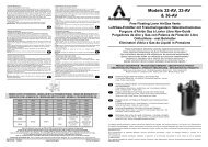
4.1.4 Anbau an Schwenkantrieb<br />
Für den Anbau an einen Schwenkantrieb nach VDI/VDE<br />
3845 steht der folgende Anbausatz zur Verfügung:<br />
4.1.4 Mounting to rotary actuator<br />
For mounting to a rotary actuator according to<br />
VDI/VDE 3845 the following mounting kit is available:<br />
• Adapter (1.0)<br />
• je vier Schrauben M6<br />
(1.1), Federringe (1.2)<br />
und Unterlegscheiben<br />
(1.3) zum Befestigen<br />
der Anbaukonsole<br />
(2.0) am <strong>Stellungsregler</strong><br />
• Anbaukonsole (2.0)<br />
• je vier Schrauben M5<br />
(2.1), Federringe (2.2)<br />
und Unterlegscheiben<br />
(2.3) zum Befestigen<br />
der Anbaukonsole am<br />
Antrieb<br />
1.0<br />
2.0<br />
1.3<br />
1.2<br />
1.1<br />
• Namur feedback shaft<br />
adapter (1.0)<br />
• Four screws, M6 (1.1),<br />
four spring washers<br />
(1.2), and four plain<br />
washers (1.3) for fastening<br />
the mounting<br />
bracket (2.0) to the<br />
positioner<br />
• Mounting bracket (2.0)<br />
• Four screws, M5 (2.1),<br />
four spring washers<br />
(2.2), and four plain<br />
washers (2.3) for fastening<br />
the mounting<br />
bracket to the actuator<br />
2.1<br />
2.2<br />
2.3<br />
Abb.15<br />
Fig. 15<br />
Anbausatz für Schwenkantriebe<br />
Mounting kit for rotary actuators)<br />
Benötigtes Werkzeug:Schraubenschlüssel Weite 10/13<br />
Innensechskantschlüssel Weite 3<br />
Tools required:<br />
Wrench 10 mm/13 mm<br />
Allen key 3 mm<br />
20
1. Adapter an <strong>Stellungsregler</strong> montieren<br />
1. Mounting adapter to positioner<br />
• Anbauposition bestimmen (parallel zum Antrieb oder<br />
um 90° versetzt)<br />
• Drehrichtung des Antriebs (rechtsdrehend oder<br />
linksdrehend) ermitteln<br />
• Schwenkantrieb in die Grundstellung fahren<br />
• anhand der Anbauposition<br />
sowie der<br />
Grundstellung und<br />
Drehrichtung des<br />
Antriebs feststellen,<br />
in welche Stellung<br />
die Achse (1) des<br />
<strong>Stellungsregler</strong>s von<br />
Hand vorverstellt und<br />
in welcher Position<br />
der Adapter (2) aufgesetzt<br />
werden muß,<br />
1<br />
damit der <strong>Stellungsregler</strong><br />
innerhalb des<br />
Arbeitsbereichs<br />
arbeiten kann (Pfeil<br />
auf Geräterückseite<br />
muß sich innerhalb<br />
des zulässigen<br />
2<br />
Bereichs bewegen,<br />
siehe Abb. 7 auf<br />
3<br />
Seite 12).<br />
• Achse vorverstellen Abb.16<br />
Fig. 16<br />
• Adapter in der geeigneten<br />
Position auf die<br />
Achse aufsetzen und mit Gewindestiften (3) fixieren;<br />
dabei muß einer der Gewindestifte verdrehsicher auf<br />
die Abflachung der Achse fixiert sein<br />
Adapter an <strong>Stellungsregler</strong> montieren<br />
Mounting adapter to positioner<br />
• Determine the mounting position (in parallel to the<br />
actuator or shifted by 90°).<br />
• Determine the direction of rotation of the actuator<br />
(clockwise or counterclockwise).<br />
• Move rotary actuator to its home position.<br />
• On the basis of the<br />
mounting position,<br />
the home position, as<br />
well as the direction<br />
of rotation it must be<br />
determined in which<br />
position the feedback<br />
shaft (1) of the positioner<br />
must be preadjusted<br />
and in which<br />
position the adapter<br />
(2) must be placed, to<br />
enable the positioner<br />
to travel within the<br />
proper range (the<br />
arrow on the rear of<br />
the device must<br />
travel within the<br />
admissible range,<br />
see Fig. 7 on page<br />
12).<br />
• Pre-adjust the feedback<br />
shaft.<br />
• Place the adapter on<br />
the feedback shaft in<br />
the appropriate position and fix it by setscrews (3);<br />
ensure that one of the setscrews is engaged on the<br />
side of the feedback shaft with the flat.<br />
21
2. <strong>Stellungsregler</strong> mit Anbaukonsole montieren 2. Mounting positioner with mounting bracket<br />
Schrauben M6<br />
M6 screws<br />
1<br />
Schrauben M5<br />
M5 screws<br />
Abb.17 Anbaukonsole (1) an <strong>TZID</strong>-C<br />
anschrauben<br />
Fig. 17 Attach mounting bracket (1)<br />
to <strong>TZID</strong>-C<br />
Abb.18<br />
Fig. 18<br />
<strong>TZID</strong>-C an Antrieb anschrauben<br />
Attach <strong>TZID</strong>-C to actuator<br />
22
4.1.5 Anbau an Regelventile 23/24, 23/25 und 23/26 4.1.5 Mounting to control valves 23/24, 23/25 and 23/26<br />
Abb.19 Integrierter Anbau an Ventil 23/24, 23/25<br />
Fig. 19: Integral mounting to valve 23/24, 23/25<br />
Abb.20 Integrierter Anbau an Regelventil 23/26<br />
Fig. 20 Integral mounting to valve 23/26<br />
23
• auf der Rückseite des <strong>TZID</strong>-C ggf. die Verschlußschraube<br />
und den eingelegten O-Ring entfernen<br />
• den pneumatischen Anschluß mit der Kennzeichnung<br />
OUT1 mit dem Verschlußstopfen verschließen<br />
Die übliche Außenverrohrung entfällt, außer beim<br />
Regelventil 23/24 und 23/25 mit der Wirkrichtung<br />
"Luft schließt/Federkraft öffnet"<br />
• bei Regelventilen 23/26 die Platine mit Schrauben<br />
am <strong>Stellungsregler</strong> befestigen und den Adapter zur<br />
Achsverlängerung aufsetzen.<br />
• Hebel mit Konusrolle auf die rückseitige Achse des<br />
<strong>Stellungsregler</strong>s montieren (korrekte Positionierung<br />
durch seitliche Abflachung der Achse gewährleistet)<br />
• Position der Konusrolle im Langloch des Hebels<br />
anhand der Markierung auf den Stellhub des Stellantriebes<br />
bzw. der Stellarmatur ausrichten<br />
• <strong>Stellungsregler</strong> mit je zwei Schrauben und zwei<br />
Federringen (Federringe nur bei Ventil 23/24 und<br />
23/25) am Stellantrieb befestigen; beim Anschrauben<br />
darauf achten, daß die Konusrolle zwischen die<br />
beiden Bolzen eintaucht, die sich zum Abgriff des<br />
Stellwertes an der Spindel befinden<br />
• If required, remove the screw plug and the inserted<br />
O-ring at the rear of the <strong>TZID</strong>-C positioner.<br />
• Close the pneumatic connection marked OUT 1 by<br />
means of the screw plug.<br />
The common external piping is dropped, except for<br />
the control valve 23/24 and 23/25 with the effective<br />
direction "air to close/spring force to open".<br />
• In case of the control valves 23/26, first mount the<br />
plate with the screws to the positioner and put on the<br />
adapter for a prolongation of the feedback shaft.<br />
• Mount the lever with the follower pin to the rear feedback<br />
shaft of the positioner; the flat on the side of the<br />
positioner feedback shaft assures a correct positioning.<br />
• Match the position of the follower pin in the oblong<br />
hole of the lever to the actuator stroke using the<br />
scale.<br />
• Mount the positioner with two screws and two spring<br />
washers (spring washers only in case of valve 23/24<br />
and 23/25) to the actuator. During mounting, ensure<br />
that the follower pin is introduced between the two<br />
studs at the spindle which serve for the pick-up of<br />
the actuator value.<br />
24
4.2 Pneumatischer Anschluß.<br />
Gefahr<br />
Beachten Sie bei der Montage und Inbetriebnahme<br />
die Sicherheitsvorschriften der pneumatischen<br />
Antriebe und die Unfallverhütungsvorschriften<br />
der Berufsgenossenschaft.<br />
Es besteht Verletzungsgefahr durch<br />
die hohen Stellkräfte der Antriebe!<br />
Stellen Sie durch geeignete Maßnahmen<br />
sicher, daß der maximale Arbeitsdruck des<br />
<strong>Stellungsregler</strong>s von 6 bar auch im Störfall<br />
nicht überschritten werden kann. Andernfalls<br />
besteht die Gefahr, daß der <strong>Stellungsregler</strong><br />
oder der Stellantrieb beschädigt werden.<br />
Beachten Sie den maximalen Arbeitsdruck<br />
des Antriebs.<br />
Betreiben Sie den <strong>Stellungsregler</strong> ausschließlich<br />
mit öl-, wasser- und staubfreier<br />
Instrumentenluft nach DIN/ISO 8573-1,<br />
Klasse 3:<br />
Reinheit<br />
max. Teilchengröße: 5 µm<br />
max. Teilchendichte: 5 mg/m 3<br />
Ölgehalt<br />
max. Konzentration: 1 mg/m 3<br />
Drucktaupunkt<br />
Maximalwert:<br />
10 K unter Betriebstemperatur<br />
Entfernen Sie vor dem Anschließen der Luftleitung<br />
Staub, Späne oder andere Schmutzpartikel<br />
durch Ausblasen.<br />
4.2 Pneumatic connection<br />
Warning<br />
Caution<br />
When mounting and commissioning observe<br />
the safety regulations of the pneumatic actuators<br />
and the accident prevention rules of<br />
the Employers Liability Insurance Association.<br />
There is danger of injuries caused by<br />
the high torque forces produced by the actuators!<br />
Take suitable measures to ensure that even<br />
in case of malfunctions the positioner’s max.<br />
admissible operating pressure of 6 bar<br />
(90 psi) is not exceeded. Otherwise, the positioner<br />
and/or the actuator can be damaged.<br />
Do not exceed the maximum operating pressure<br />
of the actuator.<br />
The positioner must be supplied with instrument<br />
air that is free of oil, water and dust according<br />
to DIN/ISO 8573-1, Class 3:<br />
Purity<br />
max. particle size: 5 µm<br />
max. particle density: 5 mg/m 3<br />
Oil contents<br />
max. concentration: 1 mg/m 3<br />
Pressure dew point<br />
Maximum value:<br />
10 K below<br />
operating<br />
temperature<br />
Before connecting the air pipes, remove<br />
dust, splinters and other particles by blowing<br />
them out.<br />
25
Alle pneumatischen Leitungsanschlüsse<br />
befinden<br />
sich auf der rechten<br />
Seite des Geräts (siehe<br />
Abb. 21).<br />
Für die pneumatischen<br />
Anschlüsse sind Gewindebohrungen<br />
G1/4 oder<br />
1/4-18 NPT vorhanden.<br />
Die entsprechenden<br />
Rohrverschraubungen<br />
sind kundenseitig beizustellen.<br />
Wir empfehlen, für<br />
den Anschluß Leitungen<br />
mit den Abmessungen 6 x<br />
1 mm zu verwenden.<br />
NPT ¼<br />
M12x1<br />
G¼<br />
Abb.21<br />
Stimmen Sie die Höhe<br />
Fig. 21<br />
des Zuluftdrucks auf den<br />
Stelldruck im Stellantrieb ab, der für die Aufbringung der<br />
Stellkraft benötigt wird. Die Grenzwerte des <strong>Stellungsregler</strong>s<br />
liegen bei 1,4 und 6 bar.<br />
Filter<br />
OUT 1 OUT 2<br />
Pneumatische Ausgänge<br />
Pneumatic outputs<br />
Filterschraube<br />
Filter screw plug<br />
Zuluft<br />
Air supply<br />
Pneumatische Anschlüsse<br />
Pneumatic connections<br />
All pneumatic piping connections<br />
are located at<br />
the right-hand side of the<br />
device (see Fig. 21).<br />
The threaded bores<br />
G 1/4 or 1/4-18 NPT,<br />
respectively, are provided.<br />
The corresponding<br />
screwed pipe<br />
connections have to be<br />
supplied by the customer.<br />
We recommend pipes<br />
with the dimension 6x1<br />
mm for the pneumatic<br />
piping.<br />
The amount of supply<br />
pressure has to be<br />
matched to the working<br />
pressure necessary for the actuation. The values 1.4<br />
and 6 bar are the limit values of the positioner.<br />
Verrohren Sie die Anschlüsse gemäß Kennzeichnung<br />
wie folgt:<br />
Kennzeichnung Anschlußverrohrung<br />
- Zuluft, Druck 1,4...6 bar<br />
OUT1 Stelldruck zum Stellantrieb<br />
OUT2 Stelldruck zum Stellantrieb<br />
(2. Anschluß bei doppeltwirkendem<br />
Antrieb)<br />
The connections have to be arranged, according to their<br />
marks, in the following way:<br />
Mark Connection piping<br />
- Air supply, pressure 1.4...6 bar<br />
(20...90 psi)<br />
OUT1 Output pressure, to actuator<br />
OUT2 Output pressure, to actuator<br />
(for double-acting actuators)<br />
26
4.3 Elektrischer Anschluß<br />
Gefahr<br />
Beachten Sie bei der elektrischen Installation<br />
die einschlägigen VDE-Vorschriften und<br />
die Unfallverhütungsvorschriften der Berufsgenossenschaft.<br />
Beachten Sie die einschlägigen Normen und<br />
Sicherheitsvorschriften für die Errichtung<br />
und den Betrieb elektrischer Anlagen.<br />
Beachten Sie zusätzlich die Normen, Verordnungen<br />
und Richtlinien für die Errichtung<br />
und den Betrieb von Ex-Anlagen, sofern Exzugelassene<br />
Geräte zum Einsatz kommen.<br />
Schließen Sie an den Analogeingängen der<br />
Klemmen +11/-12 ausschließlich Signalkreise<br />
mit eingeprägtem Strom 4...20 mA an.<br />
Beim Anschluß eines Spannungsgebers, z.B.<br />
eines 24V-DC-Netzteils, wird der Eingang zerstört.<br />
Der Maximalstrom darf im Störfall (auch bei<br />
Verpolung) 500 mA nicht überschreiten.<br />
Beachten Sie bei der Verdrahtung die elektrischen<br />
Grenzwerte gemäß Kapitel 8 "Technische<br />
Daten".<br />
Verlegen Sie die Signalleitung nicht zusammen<br />
mit Energieversorgungsleitungen, da<br />
diese in ihrem näheren Umfeld Störfelder erzeugen,<br />
die die Meßwerte in der Signalleitung<br />
beeinträchtigen.<br />
4.3 Electrical connection<br />
Danger<br />
Caution<br />
During the electrical installation observe the<br />
common VDE safety regulations and the accident<br />
prevention rules of the Employers Liability<br />
Insurance Association.<br />
Observe the common standards/safety regulations<br />
for the set-up and the operation of<br />
electrical installations.<br />
Observe the additional standards, regulations<br />
and guidelines for the set-up and the<br />
operation of explosion-proof installations, if<br />
explosion-proof devices are used.<br />
Only connect signal lines from controlled<br />
current sources such as mA outputs from<br />
controllers or calibrators to terminals<br />
+11/-12. Connecting directly to a 24 VDC<br />
power supply will destroy the input circuitry.<br />
The maximum current during a fault must not<br />
exceed 500 mA (even if polarity is reversed).<br />
During installation please observe the specifications<br />
in chapter 8 "Technical data" .<br />
Do not run signal cables close to power<br />
lines. Power lines produce interference in<br />
their near vicinity which impairs the signals<br />
transmitted on the line.<br />
27
Für die Kabeleinführung in<br />
das Gehäuse befinden<br />
sich auf der linken Gehäuseseite<br />
zwei Gewindebohrungen<br />
PG 13,5 oder 1/2 -<br />
14 NPT (siehe Abb. 22).<br />
Die vordere Bohrung ist<br />
mit einer Kabelverschraubung<br />
versehen, auf der<br />
hinteren sitzt ein Blindstopfen.<br />
Blindstopfen<br />
Dummy plug<br />
For the cable entry into the<br />
case two threaded holes<br />
PG 13.5 or 1/2 - 14 NPT<br />
are available on the left<br />
side of the case (see Fig.<br />
22). The front hole is<br />
equipped with a cable<br />
gland, in the back one a<br />
dummy plug is mounted.<br />
Kabelverschraubung<br />
Cable gland<br />
28<br />
Die Schraubklemmen für<br />
Leitungsquerschnitte bis<br />
max. 2,5 mm 2 im Gehäuse<br />
sind wie folgt belegt<br />
(siehe Abb. 23):<br />
• Signal 4...20 mA (1)<br />
• Binäreingang DI (2a)<br />
• Binärausgang DO (2b)<br />
• Steckmodul für digitale<br />
Rückmeldung (3)<br />
• Steckmodul für analoge<br />
Rückmeldung (4)<br />
• Schlitzinitiatoren (digitale<br />
Rückmeldung) (5)<br />
• Gehäusemasse (6)<br />
Abb.22<br />
Fig. 22<br />
4<br />
3<br />
Abb.23<br />
Fig. 23<br />
Kabeleinführung<br />
Cable entry<br />
+31 -32<br />
+41 -42<br />
+51 -52<br />
+41 -42<br />
Limit 2<br />
+51 -52<br />
Limit 1<br />
+11 -12 +81-82 +83 -84<br />
Schraubklemmen<br />
Screw-type terminals<br />
5<br />
2b<br />
2a<br />
1<br />
6<br />
The screw terminals for wire<br />
sizes up to 2.5 mm 2 inside the<br />
case are assigned as follows<br />
(see Fig. 23):<br />
• Signal 4...20 mA (1)<br />
• Digital input DI (2a)<br />
• Digital output DO (2b)<br />
• Plug-in module for digital<br />
position feedback (3)<br />
• Plug-in module for analog<br />
position feedback (4)<br />
• Proximity switches (digital<br />
position feedback) (5)<br />
• Enclosure ground (6)
4...20 mA Stellsignal, Binärsignal und Schlitzinitiatoren<br />
anschließen:<br />
• Leiter auf etwa 7-10 mm abisolieren<br />
• Leitungsenden von links in die jeweiligen<br />
Schraubklemmen einführen und Schrauben handfest<br />
anziehen (Zugang von oben)<br />
Steckmodule anschließen:<br />
• Leiter auf etwa 7-10 mm abisolieren<br />
• Leitungsenden von oben in die entsprechenden<br />
Schraubklemmen einführen und Schrauben handfest<br />
anziehen (Zugang seitlich)<br />
Connecting 4...20 mA signal, digital signal, and<br />
proximity switches:<br />
• Remove 7-10 mm (1/4 - 3/8") of the cable insulation<br />
• Insert the wire ends from the left into the appropriate<br />
screw terminal and hand-tighten the screws (access from<br />
above)<br />
Connecting the plug-in modules:<br />
• Remove 7-10 mm (1/4 - 3/8") of the cable insulation<br />
• Insert the wire ends from the top into the corresponding<br />
screw terminal and hand-tighten the screws (access from<br />
the side)<br />
Abb.24 Anschlußbelegung Fig. 24 Terminal assignment<br />
29
4.4 Inbetriebnahme<br />
Nachdem Sie den <strong>Stellungsregler</strong> <strong>TZID</strong>-C montiert und<br />
den elektrischen und pneumatischen Anschluß vorgenommen<br />
haben, können Sie das Gerät in Betrieb nehmen.<br />
Überprüfen Sie zunächst den Anbau, und passen<br />
Sie dann den <strong>TZID</strong>-C elektronisch an die Betriebsdaten<br />
des Stellantriebs bzw. der Stellarmatur an, und zwar<br />
• über einen PC mit dem Bedienprogramm "IBIS für<br />
<strong>TZID</strong>" oder "Smart Vision ® " (über Kommunikationsanschluß<br />
und LKS-Adapter oder FSK-Modem, siehe<br />
entsprechendes Benutzerhandbuch) oder<br />
• lokal über die Bedienelemente des <strong>TZID</strong>-C<br />
In dieser Betriebsanleitung wird ausschließlich die<br />
lokale Bedienung und Parametrierung beschrieben.<br />
Geräte, die bereits an anderer Stelle im Einsatz<br />
waren, ggf. vor Inbetriebnahme auf die Werkseinstellung<br />
zurücksetzen (siehe Seite 108)<br />
4.4.1 Anbau kontrollieren<br />
• <strong>TZID</strong>-C mit Druckluft zwischen 1,4 und 6 bar und<br />
einem Stromsignal zwischen 4 und 20 mA versorgen<br />
- Max. zulässigen Arbeitsdruck des<br />
Antriebs beachten<br />
- Beschriebene Reihenfolge einhalten.<br />
Zuerst die Druckluftversorgung freigeben<br />
und erst dann das 4 ... 20 mA<br />
Stromsignal zuführen.<br />
4.4 Commissioning<br />
After mounting the <strong>TZID</strong>-C positioner and making the<br />
electrical and pneumatic connections you can put the<br />
device into operation. First check the mounting and subsequently<br />
adjust the <strong>TZID</strong>-C electronically to the operating<br />
data of the actuator or valve<br />
• via a PC with the operating program "IBIS for <strong>TZID</strong>"<br />
or "Smart Vision ® " (via communication connection<br />
and LKS adapter or FSK modem, see corresponding<br />
user manuals) or<br />
• locally using the local <strong>TZID</strong>-C keypad<br />
These operating instructions only describe the local<br />
operation and setting of parameters.<br />
Devices that have previously been in operation<br />
in another installation should be defaulted to the<br />
factory settings prior to commissioning (see<br />
page 108).<br />
4.4.1 Checking the mounting<br />
• Supply compressed air between 1.4 and 6 bar (20<br />
and 90 psi) and a current signal between 4 and 20<br />
mA to the <strong>TZID</strong>-C.<br />
Caution<br />
- Observe the maximum allowable operating<br />
pressure of the actuator.<br />
- Observe the sequence described<br />
above. First supply compressed air and<br />
only then turn on the 4 ... 20 mA current<br />
signal.<br />
30<br />
Das Gerät läuft nach der Werkseinstellung in der<br />
Betriebsart 1.3 "Handverstellung im Sensorbereich"<br />
hoch. Geräte, die bereits vorher im Einsatz waren,<br />
laufen in der zuletzt benutzten Betriebsart hoch.<br />
With the factory setting, the device will start up in mode<br />
1.3 "Manual adjustment in the sensor range". Devices<br />
that have previously been in operation start up in the<br />
operating mode used last.
• folgende Schritte ausführen, um in die Betriebsart<br />
1.3 "Handverstellung im Sensorbereich" zu wechseln<br />
(eine genaue Beschreibung der Bedienelemente,<br />
Betriebsarten und Bedienebenen finden Sie<br />
in Kapitel 6):<br />
- MODE drücken und halten<br />
- zusätzlich oder drücken, bis "1.3,<br />
MAN_SENS" in der Anzeige erscheint; dann alle<br />
Tasten loslassen, um die Betriebsart zu<br />
aktivieren<br />
In der Anzeige wird der Drehwinkel in Grad<br />
(SENS_POS) angezeigt.<br />
• bzw. drücken, um das Ventil manuell bis an die<br />
Endanschläge zu fahren<br />
Wird die zweite Richtungstaste zusätzlich gedrückt,<br />
schaltet das Gerät um in den Schnellgang.<br />
Die Endanschläge sollten innerhalb des folgenden<br />
Bereichs liegen (siehe Abb. 4 auf Seite 9):<br />
Sensorbereich<br />
- 28 ° bis + 28 ° für Linearantriebe<br />
- 57 ° bis + 57° für Schwenkantriebe<br />
Mindestdifferenz zwischen den Anschlägen<br />
12 ° für Linearantriebe<br />
24 ° für Schwenkantriebe<br />
Liegen die Endanschläge außerhalb dieses<br />
Bereichs, müssen Sie die mechanische Umsetzung<br />
des Stellwegs auf den Drehwinkel korrigieren.<br />
Andernfalls wird später der Selbstabgleich mit einer<br />
Fehlermeldung abgebrochen.<br />
• Perform the following steps to switch to operating<br />
mode 1.3 "Manual adjustment in the sensor range"<br />
(more detailed descriptions of the operating elements,<br />
operating modes, and operating levels are to<br />
be found in chapter 6):<br />
- Press and hold MODE<br />
- In addition, press or until "1.3, MAN_SENS"<br />
is indicated on the display; then, release all buttons<br />
to activate the operating mode.<br />
The display indicates the rotation angle in<br />
degrees (SENS_POS).<br />
• Press or to drive the valve manually to the limit<br />
stops.<br />
If the second arrow button is also pressed, the<br />
device switches to fast travel.<br />
The limit stops should be within the following range<br />
(see Fig. 4 on page 9):<br />
Sensor range<br />
- 28 ° to + 28 ° for linear actuators<br />
- 57 ° to + 57° for rotary actuators<br />
Minimum difference between limit stops<br />
12 ° for linear actuators<br />
24 ° for rotary actuators<br />
If the limit stops are outside this range, the mechanical<br />
transfer of the actuator range to the rotation<br />
angle must be corrected. Otherwise, the Autoadjust<br />
function started later will stop due to a position error<br />
message.<br />
31
Alle für die Grundkonfiguration benötigten Parameter<br />
sind in der Parametergruppe P1._ (STANDARD) zusammengefaßt.<br />
Wechseln Sie in die Konfigurationsebene.<br />
Hierzu<br />
• und gleichzeitig drücken und halten<br />
• zusätzlich einmal kurz ENTER drücken<br />
In der Anzeige wird ein Countdown angezeigt.<br />
Die Richtungstasten so lange gedrückt halten, bis<br />
der Countdown beendet ist, sonst wird der<br />
Umschaltvorgang vorzeitig abgebrochen.<br />
• und loslassen<br />
Sie gelangen direkt in die Parametergruppe P1._,<br />
Parameter 1.0 "ACTUATOR".<br />
Führen Sie anschließend die in Kapitel 4.4.2 bis 4.4.6<br />
beschriebenen Schritte durch, um den <strong>Stellungsregler</strong><br />
an den Antrieb und an die Betriebsbedingungen anzupassen.<br />
Eine genaue Beschreibung der Bedienelemente,<br />
Betriebsarten und Bedienebenen finden Sie in<br />
Kapitel 6.<br />
4.4.2 Antriebsart festlegen<br />
Konfigurieren Sie den <strong>Stellungsregler</strong> <strong>TZID</strong>-C für den<br />
Antrieb. Drücken Sie hierzu oder , um die<br />
gewünschte Antriebsart auszuwählen (LINEAR = Linearantrieb,<br />
ROTARY= Schwenkantrieb)<br />
4.4.3 Selbstabgleich durchführen<br />
• MODE drücken und halten<br />
• zusätzlich kurz drücken, Tasten loslassen<br />
Die Anzeige springt um auf Parameter 1.1<br />
"AUTO_ADJ" (Selbstabgleich), Einstellung "START"<br />
All parameters required for the basic configuration are<br />
combined in parameter group P1._ (STANDARD). Proceed<br />
as described below to change over to the configuration<br />
level:<br />
• Simultaneously press and hold and .<br />
• In addition, briefly press ENTER.<br />
The display indicates a countdown.<br />
Press and hold the direction buttons until the countdown<br />
to zero is finished; otherwise, switch-over is<br />
not executed.<br />
• Release and .<br />
You go directly to parameter group P1._ , parameter<br />
1.0 "ACTUATOR".<br />
After this, use the steps described in chapter 4.4.2<br />
through 4.4.6 to match the positioner to the actuator and<br />
the operating conditions. For more detailed information<br />
of the operating elements, operating modes, and operating<br />
levels refer to chapter 6.<br />
4.4.2 Determining the actuator type<br />
Configure the <strong>TZID</strong>-C positioner for the corresponding<br />
actuator. Press or to select the desired actuator<br />
type (LINEAR or ROTARY).<br />
4.4.3 Running Autoadjust<br />
• Press and hold MODE.<br />
• In addition, briefly press , release the buttons.<br />
The display switches to parameter 1.1 "AUTO_ADJ"<br />
(Autoadjust), setting "START"<br />
32
• ENTER drücken und halten<br />
Ein Countdown von 3 auf 0 wird angezeigt.<br />
ENTER bis zum Ablauf des Countdowns festhalten,<br />
dann loslassen.<br />
Der <strong>Stellungsregler</strong> startet den Selbstabgleich (weitere<br />
Informationen hierzu siehe Seite 64).<br />
• bei erfolgreichem Selbstabgleich die Meldung<br />
"COMPLETE" mit ENTER bestätigen<br />
Ggf. wird der Selbstabgleich abgebrochen und eine<br />
Fehlermeldung erscheint (weitere Informationen<br />
hierzu siehe Seite 64).<br />
• falls erforderlich, mit der Einstellung des Toleranzbandes<br />
fortfahren (siehe Kapitel 4.4.4); sonst direkt<br />
zu Parameter P1.3 oder P1.4 wechseln.<br />
4.4.4 Toleranzband einstellen<br />
Der kleinstmögliche Wert des Toleranzbandes wird beim<br />
Selbstabgleich ermittelt, während des laufenden Regelbetriebes<br />
adaptiv überprüft und ggf. korrigiert. Nur in<br />
Ausnahemfällen (z.B. bei sehr kleinen Antrieben) sollten<br />
Sie einen größeren Wert einstellen. (siehe Seite 68).<br />
• MODE drücken und halten<br />
• zusätzlich kurz drücken, Tasten loslassen<br />
Die Anzeige springt um auf Parameter 1.2<br />
"TOL_BAND" (Toleranzband). Der Wert wird in %<br />
bezogen auf den Ventilbereich angegeben (siehe<br />
Seite 68)<br />
• oder drücken, um den Wert zu verändern<br />
• ggf. die Einstellungen testen (siehe Kapitel 4.4.5),<br />
sonst mit dem Speichern fortfahren (Kapitel 4.4.6)<br />
• Press and hold ENTER.<br />
A countdown from 3 to 0 is indicated.<br />
Continue to hold ENTER until the countdown has<br />
run down, then release ENTER.<br />
The positioner starts Autoadjust (see page 64 for<br />
details).<br />
• If Autoadjust is successful, the message "COM-<br />
PLETE" pops up. Confirm with ENTER.<br />
In case of troubles Autoadjust may be cancelled, and<br />
an error messages is shown in the display. Refer to<br />
page 64 for details.<br />
• If required, continue with setting the tolerance band<br />
(see chapter 4.4.4); normally, you can directly<br />
change over to parameter P1.3 or P1.4.<br />
4.4.4 Setting the tolerance band<br />
During Autoadjust the smallest possible value of the tolerance<br />
band is determined and adaptively checked and<br />
corrected, if necessary, during the ongoing controlling<br />
operation. Only in some special cases (e.g. with very<br />
small actuators) you should set a bigger value for the tolerance<br />
band (see page 68).<br />
• Press and hold MODE.<br />
• In addition, briefly press , release the buttons.<br />
The display switches to parameter 1.2 "TOL_BAND"<br />
(tolerance band). The value is indicated as a percentage<br />
of the valve range (see page 68)<br />
• Press or to change the value.<br />
• If required, continue with testing the settings (see<br />
chapter 4.4.5), otherwise save (see chapter 4.4.6).<br />
33
4.4.5 Einstellungen testen<br />
34<br />
Mit dem Test wird der Regler aktiv. Sie können prüfen,<br />
welche Auswirkungen die vorgenommenen Änderungen<br />
haben. Hierzu<br />
• MODE drücken und halten<br />
• zusätzlich kurz drücken, Tasten loslassen<br />
Die Anzeige springt um auf Parameter 1.3 "TEST".<br />
• ENTER drücken und halten<br />
Ein Countdown von 3 auf 0 wird angezeigt.<br />
ENTER bis zum Ablauf des Countdowns festhalten<br />
und dann loslassen.<br />
Der <strong>Stellungsregler</strong> aktiviert den Testmodus (siehe<br />
Seite 69)<br />
Der Test wird nach zwei Minuten automatisch beendet.<br />
Durch Drücken einer beliebigen Taste können Sie ihn<br />
auch jederzeit abbrechen.<br />
4.4.6 Einstellungen speichern<br />
• MODE drücken und halten<br />
• zusätzlich kurz drücken, Tasten loslassen<br />
Die Anzeige springt um auf Parameter 1.4 "EXIT"<br />
(zurück zur Arbeitsebene)<br />
• oder drücken, um "NV_SAVE" (ausfallsicher<br />
speichern) auszuwählen<br />
• ENTER drücken bis zum Ablauf des Countdowns<br />
von 3 auf 0festhalten, dann ENTER loslassen.<br />
Der <strong>Stellungsregler</strong> speichert die Daten und kehrt in<br />
die zuletzt gewählte Betriebsart in der Arbeitsebene<br />
zurück (siehe Seite 69).<br />
Die Inbetriebnahme ist damit abgeschlossen.<br />
4.4.5 Testing the settings<br />
With this test the controller is activated. You can check<br />
the effects of the changes you made. Proceed as<br />
described below:<br />
• Press and hold MODE.<br />
• In addition, briefly press , release the buttons.<br />
The display switches to parameter 1.3 "TEST".<br />
• Press and hold ENTER.<br />
A countdown from 3 to 0 is indicated.<br />
Continue to hold ENTER until the countdown has<br />
run down, then release ENTER. The positioner<br />
activates the test mode (see page 69).<br />
The test is automatically stopped after two minutes and<br />
can also be cancelled by pressing any button.<br />
4.4.6 Saving the settings<br />
• Press and hold MODE.<br />
• In addition, briefly press , release the buttons.<br />
The display switches to parameter 1.4 "EXIT" (back<br />
to operating level).<br />
• Press or to select "NV_SAVE" (save in the nonvolatile<br />
memory).<br />
• Press and hold ENTER.<br />
Continue to hold ENTER until the countdown from<br />
3 to 0 has run down, then release ENTER. The<br />
positioner saves the data and returns to the last previous<br />
operating mode on the operating level (see<br />
page 69).<br />
This completes the commissioning procedure.
Process Automation<br />
5 Nachträglicher Einbau von Optionen<br />
Sie können die Erweiterungsoptionen entweder mit dem<br />
Gerät mitbestellen - dann werden sie im montierten<br />
Zustand ausgeliefert - oder sie nachträglich installieren.<br />
Gehen Sie dazu vor wie nachstehend beschrieben.<br />
5.1 Mechanische Stellungsanzeige<br />
5 Installation of option cards<br />
Options can either be ordered together with the device -<br />
in that case they are delivered already mounted - or they<br />
can be installed later. In the latter case proceed as follows:<br />
5.1 Mechanical position indicator<br />
• beide Schrauben am<br />
Gehäusedeckel lösen<br />
und den Deckel<br />
abnehmen<br />
• spezielle verlängerte<br />
Achse aufstecken<br />
• Stellungsanzeige auf<br />
die Achse aufstecken<br />
Aufkleber<br />
Stickers<br />
Stellungsanzeige<br />
Position indicator<br />
%<br />
• Loosen both screws at<br />
the case cover and<br />
remove the cover.<br />
• Install the long feedback<br />
shaft.<br />
• Slip the position indicator<br />
onto the feedback<br />
shaft.<br />
• Spezialdeckel mit transparenter<br />
Kuppel aufsetzen<br />
und am Gehäuse<br />
festschrauben<br />
Elsag Bailey<br />
Hartmann & Braun<br />
SENSYCON<br />
• Mount the special<br />
cover with the transparent<br />
dome and fasten<br />
to the case.<br />
• Symbolaufkleber zum<br />
Markieren der min.<br />
und max. Ventilstellung<br />
auf dem Deckel<br />
anbringen<br />
Abb.25<br />
Fig. 25<br />
Transparente Kuppel<br />
Transparent dome<br />
<strong>TZID</strong>-C mit mechanischer Stellungsanzeige<br />
<strong>TZID</strong>-C with mechanical position indicator<br />
• Attach the stickers for<br />
marking the minimum<br />
and maximum valve<br />
stroke on the cover.<br />
35
5.2 Steckmodul für analoge Rückmeldung<br />
Nachträglichen Einbau des Steckmodules<br />
für analoge Rückmeldung nur unter Werkstattbedingungen<br />
und im spannungslosen<br />
Zustand durchführen. Andernfalls kann die<br />
empfindliche Elektronik des Geräts beschädigt<br />
werden.<br />
• Stromversorgung (4...20 mA Signal) unterbrechen<br />
• Druckluftversorgung unterbrechen<br />
• beide Schrauben am Gehäusedeckel lösen und<br />
Deckel abnehmen<br />
• elektrische Verdrahtungen entfernen<br />
• ggf. Stellungsanzeige von der Achse abnehmen<br />
• wenn der mechanische Bausatz für digitale Rückmeldung<br />
mit den entsprechenden Steuerfahnen<br />
installiert ist, die Achse herausschrauben<br />
• Schutzvorrichtung(en) zur Vermeidung elektrostatischer<br />
Entladungen (z.B. Erdungsarmband) anlegen<br />
Elektrostatische Entladung in die beim<br />
nächsten Schritt freigelegte Elektronik<br />
vermeiden. Andernfalls können elektronische<br />
Bauteile zerstört werden.<br />
• Schrauben (vier) lösen, mit denen die Kunststoffabdeckung<br />
am Gehäuse befestigt ist; Abdeckung<br />
abnehmen<br />
• Steckmodul für analoge Rückmeldung in den linken<br />
Steckplatz im Gehäuse einsetzen (siehe Abb. 26 auf<br />
Seite 37); darauf achten, daß die Platine in die Führungen<br />
im Gehäuse eingreift und sich das Flachbandkabel<br />
mit dem Anschlußstecker auf der rechten<br />
Seite befindet<br />
5.2 Plug-in module for analog position feedback<br />
Installation of the plug-in module for analog<br />
position feedback should only be done under<br />
shop conditions and when the <strong>TZID</strong>-C is<br />
not powered. Otherwise the sensitive electronics<br />
of the device may be damaged.<br />
• Turn off the power supply (4...20 mA signal).<br />
• Turn off the compressed air supply.<br />
• Loosen both screws at the case cover and remove<br />
the cover.<br />
• Remove the electrical wiring.<br />
• Remove the position indicator from the feedback<br />
shaft (if applicable).<br />
• If the mechanical kit for digital position feedback is<br />
installed with the corresponding slot sensors,<br />
remove the feedback shaft.<br />
• Take ESD (electrostatic discharge) precautions (i.e.<br />
ESD wrist-band).<br />
Avoid electrostatic discharge to the<br />
electronic circuitry that is exposed during<br />
the next step. Not taking ESD pre-<br />
Caution<br />
cautions could result in damage to the<br />
electronics.<br />
• Loosen the screws (four) that hold the plastic cover<br />
to the case and remove the cover.<br />
• Insert the plug-in module for analog position feedback<br />
into the left slot into the case (see Fig. 26 on<br />
page 37); ensure that the board engages into the<br />
case guides and that the flat cable with the connector<br />
is on the right-hand side.<br />
36
• Steckmodul an die<br />
Grundplatine anschließen<br />
(siehe Abb. 26)<br />
• Kunststoffabdeckung<br />
wieder aufsetzen und<br />
am Gehäuse festschrauben<br />
• ggf. Achse (mit Steuerfahnen)<br />
einschrauben<br />
• ggf. Stellungsanzeige<br />
auf die Achse aufstekken<br />
• alle elektr. Ein- und<br />
Ausgänge anschließen,<br />
auch den neuen<br />
Abb.26<br />
Analogausgang (siehe<br />
Fig. 26<br />
Kapitel 8.2 "Optionen")<br />
• Druckluftversorgung freigeben<br />
• 4...20 mA Stromsignal einspeisen<br />
• ggf. Parameter für analoge Rückmeldung anpassen:<br />
- in die Konfigurationsebene wechseln<br />
(s. Seite 54)<br />
- Parametergruppe P8._ wählen (siehe Seite 98)<br />
und die Parameter P8.0...P8.3 anpassen<br />
• Gehäusedeckel wieder aufsetzen und festschrauben;<br />
Schrauben handfest anziehen<br />
Steckmodul f. analoge Rückmeldung einbauen<br />
Installing plug-in module for analog pos. feedb.<br />
• Connect the plug-in<br />
module to the motherboard<br />
(see Fig. 26).<br />
• Replace the plastic<br />
cover and fasten to the<br />
case.<br />
• Screw on the feedback<br />
shaft with slot sensors<br />
(if applicable).<br />
• Slip the position indicator<br />
onto the feedback<br />
shaft (if<br />
applicable).<br />
• Connect all electrical<br />
inputs and outputs,<br />
also the new analog<br />
output (see chapter<br />
8.2 "Optionen").<br />
• Turn on the compressed air supply.<br />
• Turn on the 4...20 mA position demand signal.<br />
• Set parameters for analog position feedback, if<br />
required:<br />
- Switch to the configuration level<br />
(see page 54).<br />
- Select parameter group P8.0 (see page 98) and<br />
adjust parameters P8.0...P8.3 .<br />
• Replace the case cover; hand-tighten the screws.<br />
37
5.3 Steckmodul für digitale Rückmeldung<br />
38<br />
Nachträglichen Einbau des Steckmodules<br />
für digitale Rückmeldung nur unter Werkstattbedingungen<br />
und im spannungslosen<br />
Zustand durchführen. Andernfalls kann die<br />
empfindliche Elektronik des Geräts beschädigt<br />
werden.<br />
• Stromversorgung (4...20 mA Signal) unterbrechen<br />
• Druckluftversorgung unterbrechen<br />
• beide Schrauben am Gehäusedeckel lösen und<br />
Deckel abnehmen<br />
• elektrische Verdrahtungen entfernen<br />
• ggf. Stellungsanzeige von der Achse abnehmen<br />
• wenn der mechanische Bausatz für digitale Rückmeldung<br />
mit den entsprechenden Steuerfahnen<br />
installiert ist, die Achse herausschrauben<br />
• Schutzvorrichtung(en) zur Vermeidung elektrostatischer<br />
Entladungen (z.B. Erdungsarmband) anlegen<br />
Elektrostatische Entladung in die beim<br />
nächsten Schritt freigelegte Elektronik<br />
vermeiden. Andernfalls können elektronische<br />
Bauteile zerstört werden.<br />
• Schrauben (vier) lösen, mit denen die Kunststoffabdeckung<br />
am Gehäuse befestigt ist; Abdeckung<br />
abnehmen<br />
• Steckmodul für digitale Rückmeldung in den rechten<br />
Steckplatz im Gehäuse einsetzen (siehe Abb. 27 auf<br />
Seite 39); darauf achten, daß die Platine in die Führungen<br />
im Gehäuse eingreift und sich das Flachbandkabel<br />
mit dem Stecker rechts befindet<br />
• Steckmodul an Grundplatine anschließen (siehe<br />
Abb. 27).<br />
5.3 Plug-in module for digital position feedback<br />
Installation of the plug-in module for digital<br />
position feedback should only be done under<br />
shop conditions and when the <strong>TZID</strong>-C is<br />
not powered. Otherwise the sensitive electronics<br />
of the device may be damaged.<br />
• Turn off the power supply (4...20 mA signal).<br />
• Turn off the compressed air supply.<br />
• Loosen both screws at the case cover and remove<br />
the cover.<br />
• Remove the electrical wiring.<br />
• Remove the position indicator from the feedback<br />
shaft (if applicable).<br />
• If the mechanical kit for digital position feedback is<br />
installed with the corresponding slot sensors,<br />
remove the feedback shaft.<br />
• Take ESD (electrostatic discharge) precautions (i.e.<br />
ESD wrist-band).<br />
Avoid electrostatic discharge to the<br />
electronic circuitry that is exposed during<br />
the next step. Not taking ESD pre-<br />
Caution<br />
cautions could result in damage to the<br />
electronics.<br />
• Loosen the screws (four) that hold the plastic cover<br />
to the case and remove the cover.<br />
• Insert the plug-in module for digital position feedback<br />
into the right-hand slot into the case (see Fig. 27 on<br />
page 39); ensure that the board engages into the<br />
case guides and that the flat cable with the connector<br />
is on the right-hand side.<br />
• Connect the plug-in module to the motherboard (see<br />
Fig. 27).
• Kunststoffabdeckung<br />
wieder aufsetzen und<br />
am Gehäuse festschrauben<br />
• ggf. Achse (mit Steuerfahnen)<br />
einschrauben<br />
• ggf. Stellungsanzeige<br />
auf die Achse<br />
aufstecken<br />
• alle elektr. Ein- und<br />
Ausgänge anschließen,<br />
auch den neuen<br />
Digitalausgang (siehe<br />
Kapitel 8.2 "Optionen")<br />
• Druckluftversorgung Abb.27<br />
freigeben<br />
Fig. 27<br />
• 4...20 mA Stromsignal<br />
einspeisen<br />
• Selbstabgleich durchführen (s. Seite 64)<br />
• ggf. den oberen und unteren Schaltpunkt für die digitale<br />
Rückmeldung wie folgt einstellen:<br />
- in die Konfigurationsebene wechseln (s. Seite<br />
54).<br />
- Parameter P4.1 wählen (siehe Seite 55) und<br />
unteren Schaltpunkt einstellen (siehe Seite 55<br />
und Seite 79)<br />
- Parameter P4.2 wählen und oberen Schaltpunkt<br />
einstellen (siehe Seite 55 und Seite 79)<br />
• Gehäusedeckel aufsetzen und anschrauben;<br />
Schrauben handfest anziehen<br />
Steckmodul f. digitale Rückmeldung einbauen<br />
Installing plug-in module for digital pos. feedb.<br />
• Replace the plastic<br />
cover and fasten to the<br />
case.<br />
• Screw on the feedback<br />
shaft with slot sensors<br />
(if applicable).<br />
• Slip the position indicator<br />
onto the feedback<br />
shaft (if applicable).<br />
• Connect all electrical<br />
inputs and outputs, also<br />
the new digital output<br />
(see chapter 8.2<br />
"Optionen").<br />
• Turn on the compressed<br />
air supply.<br />
• Turn on the 4...20 mA<br />
position demand signal.<br />
• Run Autoadjust (s. page 64)<br />
• If necessary, adjust upper and lower switching point<br />
for the digital position feedback as follows:<br />
- Switch to configuration level (see page 54).<br />
- Select parameter P4.1 (see page 55) and adjust<br />
lower switching point (see page 55/page 79).<br />
- Select parameter P4.2 and adjust upper switching<br />
point (see page 55/page 79).<br />
• Replace the case cover; hand-tighten the screws.<br />
39
5.4 Mechanischer Bausatz für digitale<br />
Rückmeldung<br />
Sie können den mechanischen Bausatz für<br />
digitale Rückmeldung nur installieren, wenn<br />
das Gerät über eine mechanische Stellungsanzeige<br />
verfügt. Nur der mit dieser Option<br />
ausgelieferte Spezialdeckel mit transparenter<br />
Kuppel bietet ausreichend Platz für die<br />
verlängerte Achse und die beiden Steuerfahnen.<br />
• Stromversorgung (4...20 mA Signal) unterbrechen<br />
• Druckluftversorgung unterbrechen<br />
• beide Schrauben am Gehäusedeckel lösen und<br />
Deckel abnehmen<br />
• Stellungsanzeige von der Achse abnehmen<br />
• Achse abschrauben<br />
• Platine mit Schlitzinitiatoren aufsetzen und am<br />
Gehäuse anschrauben; Schrauben handfest anziehen;<br />
gleichzeitig spezielle Achse mit den beiden<br />
Steuerfahnen aufsetzen und vorsichtig einschrauben<br />
Verletzungsgefahr durch scharfkantige<br />
Steuerfahnen<br />
• Stellungsanzeige auf die Achse aufsetzen<br />
• Schlitzinitiatoren anschließen (siehe Fig. 28 auf<br />
Seite 41<br />
• Druckluftversorgung freigeben<br />
• 4...20 mA Stromsignal einspeisen<br />
5.4 Mechanical kit for digital position feedback<br />
The mechanical kit for digital position feedback<br />
can only be installed in a device with<br />
mechanical position indicator. Only the special<br />
cover with transparent dome delivered<br />
with this option provides sufficient space for<br />
the long feedback shaft and the two slot sensors.<br />
• Turn off the power supply (4...20 mA signal).<br />
• Turn off the compressed air supply.<br />
• Loosen both screws at the case cover and remove<br />
the cover.<br />
• Remove the position indicator from the feedback<br />
shaft.<br />
• Remove the feedback shaft.<br />
• Fasten board with proximity switches to the case,<br />
hand-tighten the screws. At the same time mount the<br />
special feedback shaft with the two slot sensors and<br />
screw it in carefully.<br />
Caution<br />
Danger of injuries. The slot sensors are<br />
sharp.<br />
• Replace the position indicator to the feedback shaft.<br />
• Connect the proximity switches (see Fig. 28 on page<br />
41).<br />
• Turn on the compressed air supply.<br />
• Turn on the 4...20 mA position demand signal.<br />
40
• ggf. den unteren und oberen Schaltpunkt für digitale<br />
Rückmeldung wie folgt einstellen:<br />
- Betriebsart 1.2 anwählen (siehe Seite 53) und<br />
das Stellglied von Hand in die untere Schaltposition<br />
fahren (s. Seite 59).<br />
- mit einem Schraubendreher die Steuerfahne<br />
von Schlitzinitiator 1 (unterer Kontakt, siehe Abb.<br />
28) bis zur Kontaktgabe (d.h. bis kurz vor dem<br />
Eintauchen in den Schlitzinitiator) auf der Achse<br />
verstellen; die Steuerfahne taucht bei Rechtsdrehung<br />
der Achse in Schlitzinitiator 1 ein<br />
(Blickrichtung von vorn)<br />
- Stellglied von Hand in die obere Schaltposition<br />
fahren<br />
• If required, adjust the lower and upper switching<br />
points for the digital position feedback as follows:<br />
- Select operating mode 1.2 (see page 53) and<br />
move the actuator manually to the lower switching<br />
position (see page 59).<br />
- Use a screwdriver to adjust the slot sensor of<br />
proximity switch 1 on the feedback shaft (lower<br />
contact, see Fig. 28) until it closes the contact<br />
(i.e. just before introducing into the proximity<br />
switch); the slot sensor introduces into proximity<br />
switch 1 when turning the feedback<br />
shaft clockwise (as seen from the front).<br />
- Move the actuator manually to the upper switching<br />
position.<br />
Abb.28<br />
Fig. 28<br />
Mechanischer Bausatz für digitale Rückmeldung<br />
Mechanical kit for digital position feedback<br />
41
- mit einem Schraubendreher die Steuerfahne von<br />
Schlitzinitiator 2 (oberer Kontakt, siehe Abb. 28 )<br />
bis zur Kontaktgabe (d.h. bis kurz vor dem Eintauchen<br />
in den Schlitzinitiator) auf der Achse<br />
verstellen; die Steuerfahne taucht bei Linksdrehung<br />
der Achse in Schlitzinitiator 2 ein<br />
(Blickrichtung von vorn)<br />
• Gehäusedeckel aufsetzen und am Gehäuse<br />
anschrauben; Schrauben handfest anziehen<br />
- Use a screwdriver to adjust the slot sensor of<br />
proximity switch 2 on the feedback shaft (upper<br />
contact, see Fig. 28) until it closes the contact<br />
(i.e. just before introducing into the proximity<br />
switch); the slot sensor introduces into proximity<br />
switch 2 when turning the feedback<br />
shaft counterclockwise (as seen from the<br />
front).<br />
• Replace the case cover; hand-tighten the screws.<br />
42
5.5 Manometerblock und Filterregler<br />
• bei einfachwirkendem Antrieb Stopfen für Ausgang<br />
OUT2 entfernen (Manometerblock enthält Stopfen)<br />
• Manometerblock mit mitgelieferten Schrauben seitlich<br />
am Gehäuse des <strong>TZID</strong>-C anschrauben; dabei auf korrekten<br />
Sitz der O-Ringe achten<br />
• Filterregler so montieren, daß Filtergehäuse senkrecht<br />
steht und Kondenswasser ungehindert ablaufen kann<br />
• Versorgungsdruck für <strong>TZID</strong>-C am Filterreglers einstellen;<br />
max. Druck von 16 bar auf der Eingangsseite des<br />
Filterreglers beachten<br />
5.5 Pressure gage block and filter regulator<br />
• Remove the plug for output OUT2 for single-acting<br />
actuators (pressure gage block contains plug).<br />
• Mount the pressure gage block with the supplied<br />
screws on the right hand side of the <strong>TZID</strong>-C; ensure<br />
the correct seating of the O-rings.<br />
• Mount the filter regulator with the filter housing vertically<br />
such that condensed water can run off freely.<br />
• Adjust the supply pressure for the <strong>TZID</strong>-C at the filter<br />
regulator; do not exceed max. pressure of 16 bar<br />
(235 psi) at the input side of the filter regulator.<br />
Abb.29<br />
Fig. 29<br />
Manometerblock mit Filterregler<br />
Pressure gage block with filter regulator<br />
43
5.6 Auswechseln des I/P-Moduls<br />
Das Auswechseln des I/P-Moduls (pneumatische Ausgabeeinheit<br />
des <strong>Stellungsregler</strong>s <strong>TZID</strong>-C) kann erforderlich<br />
sein bei<br />
• Änderung des Stellausgangs<br />
einfachwirkend doppeltwirkend<br />
• Änderung der Sicherheitsstellung<br />
entlüftet blockiert<br />
• starker Verschmutzung oder Verölung durch nicht<br />
ordnungsgemäß aufbereitete Zuluft.<br />
Austausch des I/P-Moduls immer unter<br />
Werkstattbedingungen und im spannungslosen<br />
Zustand durchführen. Andernfalls<br />
kann die empfindliche Elektronik des Geräts<br />
beschädigt werden.<br />
5.6 Replacing the I/P module<br />
Replacing the I/P module (pneumatic output unit of the<br />
<strong>TZID</strong>-C positioner) may be necessary when<br />
• changing the output<br />
from single-acting to double-acting<br />
• changing the safety position<br />
from fail/safe to fail/freeze and v.v.<br />
• dirt or oil has accumulated due to poorly conditioned<br />
supply air.<br />
Caution<br />
Replacing the I/P module should only be<br />
done under shop conditions and when the<br />
<strong>TZID</strong>-C is not powered. Otherwise the<br />
sensitive electronics of the device may be<br />
damaged.<br />
Vorgehensweise:<br />
• Stromversorgung (4...20 mA Signal) unterbrechen<br />
• Druckluftversorgung unterbrechen<br />
• beide Schrauben am Gehäusedeckel lösen und<br />
Deckel abnehmen<br />
• elektrische Verdrahtungen entfernen<br />
• ggf. Stellungsanzeige von der Achse abnehmen<br />
• wenn der mechanische Bausatz für digitale Rückmeldung<br />
mit den entsprechenden Steuerfahnen<br />
installiert ist, die Achse herausschrauben<br />
• Schutzvorrichtung(en) zur Vermeidung elektrostatischer<br />
Entladungen (z.B. Erdungsarmband) anlegen<br />
Procedure:<br />
• Turn off the power supply (4...20 mA signal).<br />
• Turn off the compressed air supply.<br />
• Loosen both screws at the case cover and remove<br />
the cover.<br />
• Remove the electrical wiring.<br />
• Remove position indicator from feedback shaft (if<br />
applicable).<br />
• If the mechanical kit for digital position feedback is<br />
installed with the corresponding slot sensors,<br />
remove the feedback shaft.<br />
• Take ESD (electrostatic discharge) precautions (i.e.<br />
ESD wrist-band).<br />
44
Elektrostatische Entladung in die beim<br />
nächsten Schritt freigelegte Elektronik<br />
vermeiden. Andernfalls können elektronische<br />
Bauteile zerstört werden.<br />
• Schrauben (vier) lösen, mit denen die Kunststoffabdeckung<br />
am Gehäuse befestigt ist; Abdeckung<br />
abnehmen<br />
• folgende Stecker von der Grundplatine abziehen:<br />
- I/P-Modul (1)<br />
- analoge Rückmeldung<br />
5 3 2 1<br />
(2) (wenn<br />
vorhanden)<br />
- digitale Rückmeldung<br />
(3) (wenn<br />
vorhanden)<br />
- Wegsensor (4)<br />
• beide Torx-Kopf-<br />
Schrauben (5) der<br />
Größe T10 lösen, mit<br />
denen die Grundplatine<br />
am Gehäuse<br />
befestigt ist; Spezialschraubendreher<br />
verwenden<br />
Fig. 30<br />
Abb.30<br />
• Grundplatine herausnehmen<br />
Grundplatine nur am Rand berühren<br />
und direkten Kontakt mit Bauteilen,<br />
Leiterbahnen und Lötstellen vermeiden<br />
Avoid electrostatic discharge to the<br />
electronic circuitry that is exposed during<br />
the next step. Not taking ESD pre-<br />
Caution<br />
cautions could result in damage to the<br />
electronics.<br />
• Loosen the screws (four) that hold the plastic cover<br />
to the case and remove the cover.<br />
• Disconnect the following connectors from the motherboard:<br />
- I/Pmodule (1)<br />
- Analog pos. feedback(2)<br />
(if<br />
present)<br />
- Digitale position<br />
feedback (3) (if<br />
present)<br />
- Position sensor<br />
(4)<br />
• Loosen the torx screws<br />
(5) of size T10 that hold<br />
the motherboard to the<br />
4 5<br />
case; use special<br />
screwdriver.<br />
Grundplatine<br />
Motherboard<br />
• Take out the motherboard.<br />
Caution<br />
Only touch the motherboard at the edges<br />
and avoid direct contact with the<br />
components, strip conductors, and soldering<br />
joints.<br />
45
• beide Schrauben (1)<br />
am I/P-Modul (2)<br />
lösen, I/P-Modul<br />
leicht ankippen und<br />
unter dem Zahnrad<br />
der Achse (3) hervorziehen<br />
O-Ringe (4)<br />
und Dichtung<br />
(5) können am<br />
I/P-Modul haften;<br />
vorsichtig<br />
lösen<br />
1<br />
6 7 4<br />
• Loosen both screws<br />
(1) at the I/P module<br />
(2), slightly tilt the I/P<br />
module and remove it<br />
from under the gear<br />
on the feedback shaft<br />
(3).<br />
O-rings (4) and<br />
sealing (5) may<br />
stick to the I/P<br />
module; remove<br />
carefully.<br />
• beim Umbau von einfach-<br />
auf doppeltwirkend<br />
zusätzlichen<br />
O-Ring (6) vor pneumatischen<br />
Ausgang<br />
OUT2 setzen und<br />
Stopfen (7) entfernen<br />
• beim Umbau von<br />
doppelt- auf einfachwirkend<br />
Ausgang<br />
OUT2 mit Stopfen (7)<br />
verschließen<br />
• neues I/P-Modul einsetzen;<br />
I/P-Modul<br />
dabei leicht ankippen<br />
und unter dem<br />
Zahnrad der Achse<br />
durchführen<br />
auf korrekten<br />
Sitz der O-Ringe<br />
(4, 6) und der<br />
Dichtung (5)<br />
achten<br />
2<br />
Abb.31<br />
Fig. 31<br />
Austausch des I/P-Moduls<br />
Replacing the I/P module<br />
5<br />
3<br />
• When converting<br />
from single- to double-acting,<br />
insert an<br />
additional O-ring (6)<br />
before the pneumatic<br />
output OUT2 and<br />
remove the plug (7).<br />
• When converting<br />
from double- to single-acting,<br />
close the<br />
output OUT2 with the<br />
plug (7).<br />
• Insert new I/P module;<br />
slightly tilt I/P module<br />
and fit under the gear<br />
on the feedback shaft.<br />
Observe correct<br />
seating of the O-<br />
Caution rings (4, 6) and<br />
the sealing (5).<br />
46
• I/P-Modul mit beiden Schrauben (1) im Gehäuse<br />
befestigen; Schrauben mit Drehmoment von 350<br />
Ncm anziehen<br />
• Grundplatine wieder einsetzen und mit den zwei<br />
Torx-Kopf-Schrauben im Gehäuse befestigen<br />
• alle Stecker wieder auf die Grundplatine aufstecken<br />
(siehe Abb. 30 auf Seite 45); darauf achten, daß alle<br />
Stecker gut einrasten<br />
• Kunststoffabdeckung wieder aufsetzen und am<br />
Gehäuse festschrauben<br />
• ggf. Platine mit den Schlitzinitiatoren aufsetzen und<br />
festschrauben.<br />
• Achse wieder aufsetzen und festschrauben<br />
• ggf. Stellungsanzeige auf die Achse aufsetzen<br />
• alle elektrischen Ein- und Ausgänge wieder<br />
anschließen (siehe Kapitel 4.3 "Elektrischer<br />
Anschluß")<br />
• beim Umbau von einfach- auf doppeltwirkend den<br />
entsprechenden Anschluß an Ausgang OUT2 vornehmen<br />
(siehe Kapitel 4.2)<br />
• 4...20 mA Stromsignal einspeisen<br />
Nach dem Wechsel des I/P-Modul-Typs<br />
(einfachwirkend doppeltwirkend oder<br />
entlüftet blockiert) unbedingt den <strong>TZID</strong>-C<br />
Gefahr<br />
wie nachstehend beschrieben an den Modul-<br />
Typ anpassen. Andernfalls kann der Antrieb<br />
das Ventil mit voller Geschwindigkeit an den<br />
Anschlag fahren. Verletzungsgefahr!<br />
• Fasten I/P module with both screws (1) in the case;<br />
torque the fasteners to 350 Ncm (31 in-lbs.<br />
• Replace the motherboard and fasten with the two<br />
torx screws in the case.<br />
• Connect all connectors on the motherboard (see Fig.<br />
30 on page 45); ensure that all connectors snap in<br />
correctly.<br />
• Replace the plastic cover and fasten to the case.<br />
• Replace the board with the proximity switches and<br />
fasten with screws (if applicable).<br />
• Replace the feedback shaft and fasten with screws.<br />
• Replace the position indicator to the feedback shaft<br />
(if applicable).<br />
• Reconnect all electrical inputs and outputs (see<br />
chapter 4.3 "Electrical connection").<br />
• When converting from single- to double-acting make<br />
the corresponding connection at output OUT2 (see<br />
chapter 4.2).<br />
• Feed in the 4...20 mA position demand signal.<br />
After changing the I/P module type (singleacting<br />
double-acting or fail/safe fail/<br />
freeze) the <strong>TZID</strong>-C must be adapted to the<br />
module type as described below. Otherwise<br />
the actuator can drive the valve at full speed<br />
to the mechanical limit stops.<br />
Danger of injuries!<br />
Warning<br />
47
• den <strong>TZID</strong>-C an den neuen I/P-Modul-Typ anpassen<br />
- in die Konfigurationsebene wechseln (siehe<br />
Seite 54).<br />
- Parametergruppe P11._ (FS / IP) wählen (siehe<br />
Seite 54 und Seite 107)<br />
- Parameter 11.0 "SAFE_POS" (Sicherheitsstellung)<br />
wählen und auf "ACTIVE" setzen (siehe<br />
Seite 55 und Seite 107)<br />
- Parameter 11.2 "I/P-Typ" wählen (siehe Seite<br />
109) und entsprechend einstellen<br />
• Druckluftversorgung freigeben<br />
• Selbstabgleich durchführen (siehe Seite 64).<br />
• Gehäusedeckel wieder aufsetzen und festschrauben;<br />
Schrauben handfest anziehen<br />
• Adjust the <strong>TZID</strong>-C to the new I/P module type.<br />
- Switch to the configuration level (see page 54).<br />
- Select parameter group P11._ (FS / IP) (see<br />
page 54 and page 107).<br />
- Select parameter 11.0 "SAFE_POS" (safe position)<br />
and set to "ACTIVE" (see page 55 and<br />
page 107).<br />
- Select parameter 11.2 "I/P type" (see page 109)<br />
and set accordingly.<br />
• Turn on the compressed air supply.<br />
• Run Autoadjust (see page 64).<br />
• Replace the case cover; hand-tighten the screws.<br />
48
6 Lokale Bedienung<br />
6.1 Allgemeines<br />
Der <strong>Stellungsregler</strong> <strong>TZID</strong>-C hat zwei Bedienebenen:<br />
• Arbeitsebene<br />
In der Arbeitsebene arbeitet der <strong>TZID</strong>-C in einer der<br />
vier möglichen Betriebsarten (zwei für automatische<br />
Regelung und zwei für Handbetrieb). Das Ändern<br />
und Speichern von Parametern ist in dieser Ebene<br />
nicht möglich. Weitere Informationen finden Sie in<br />
Kapitel 6.4<br />
• Konfigurationsebene<br />
In dieser Bedienebene können Sie die meisten Parameter<br />
des <strong>Stellungsregler</strong>s lokal ändern. Eine Ausnahme<br />
bilden die Grenzwerte des Hubzählers und<br />
des Wegzählers und die benutzerdefinierte Kennlinie,<br />
die Sie nur extern über einen PC bearbeiten<br />
können..<br />
Gefahr<br />
Während der externen Parametrierung<br />
über PC reagiert der <strong>TZID</strong>-C nicht mehr<br />
auf den Sollwertstrom. Fahren Sie den<br />
Antrieb vor der externen Parametrierung<br />
immer in die Sicherheitsstellung und aktivieren<br />
Sie die Handsteuerung.<br />
Um die Bedienung zu vereinfachen, wurden die<br />
Parameter in Parametergruppen zusammengefaßt,<br />
zwischen denen Sie mit Hilfe der Drucktaster hinund<br />
hernavigieren können (siehe Kapitel 6.2.2).<br />
In der Konfigurationsebene ist die aktive Betriebsart<br />
unterbrochen. Das I/P-Modul ist in Neutralstellung.<br />
Die Regelung ist nicht aktiv.<br />
Eine genaue Beschreibung der einzelnen Parametergruppen<br />
und Parameter finden Sie in Kapitel 6.5.<br />
6 Local operation<br />
6.1 General<br />
The <strong>TZID</strong>-C positioner has two levels:<br />
• Operating level<br />
On the operating level the <strong>TZID</strong>-C positioner is operating<br />
in one of four possible operating modes (two<br />
for automatic control and two for manual adjustment).<br />
Parameters cannot be changed or saved on<br />
this level. See chapter 6.4 for further information.<br />
• Configuration level<br />
On this level most of the parameters of the positioner<br />
can be changed locally. The PC is required to<br />
change the limit values for the stroke counter, the<br />
travel counter, and the user-defined characteristic<br />
curve..<br />
During external configuration via a PC<br />
the <strong>TZID</strong>-C does no longer respond to<br />
the position demand signal. Prior to external<br />
configuration always move the ac-<br />
Warning<br />
tuator to the safe position and activate<br />
manual adjustment.<br />
To simplify the operation, the parameters have been<br />
categorized in parameter groups through which you<br />
can navigate by means of the push buttons (see<br />
chapter 6.2.2).<br />
On the configuration level the active operating mode<br />
is deactivated. The I/P module is in neutral position,<br />
and the controlling operation is inactive.<br />
See chapter 6.5 for a detailed description of the individual<br />
parameter groups.<br />
49
6.2 Bedienelemente<br />
6.2.1 Beschreibung<br />
Der <strong>TZID</strong>-C kann lokal mit Hilfe einer Flüssigkristallanzeige<br />
über vier Drucktaster bedient werden.<br />
Flüssigkristallanzeige<br />
6.2 Operating elements<br />
6.2.1 Description<br />
The <strong>TZID</strong>-C positioner can be operated locally by means<br />
of a liquid crystal display and four push buttons.<br />
Liquid crystal display<br />
Die Flüssigkristallanzeige<br />
mit 160 Segmenten wurde<br />
speziell für den <strong>TZID</strong>-C entwickelt.<br />
Die Anzeige ist für<br />
einen Temperaturbereich<br />
von -25 °C<br />
bis +60 °C ausgelegt.<br />
Bei Temperaturen<br />
unterhalb dieses<br />
Bereichs wird die<br />
Anzeige zu träge<br />
und daher abgeschaltet.<br />
Die Anzeige (siehe Abb. 32)<br />
ist unterteilt in:<br />
• die Symbolanzeige<br />
• die Werteanzeige mit<br />
Einheit<br />
• die Bezeichneranzeige<br />
conf<br />
Symbolanzeige<br />
Symbol display<br />
Abb.32<br />
Fig. 32<br />
Werteanzeige, mit Einheit<br />
Value display, with unit<br />
Flüssigkristallanzeige<br />
Liquid crystal display<br />
o<br />
C<br />
%<br />
mA<br />
Bezeichneranzeige<br />
Designator display<br />
The liquid crystal display with 160<br />
segments has been specially<br />
designed for the <strong>TZID</strong>-C positioner.<br />
The display has been<br />
designed for a<br />
temperature range of<br />
-25 °C to +60 °C<br />
(-13 °F to +140 °F).<br />
Below these temperatures<br />
the display is too<br />
sluggish and will be<br />
switched off.<br />
The display (siehe Fig. 32) is<br />
divided into:<br />
• the symbol display<br />
• the value display with unit<br />
• the designator display<br />
50
Symbolanzeige:<br />
Über die vier Symbole werden die Betriebszustände des<br />
<strong>Stellungsregler</strong>s angezeigt.<br />
Symbol display:<br />
The operating modes of the positioner are indicated by<br />
four symbols.<br />
Das Schlüsselsymbol signalisiert, daß eine<br />
Bedien- bzw. Zugriffssperre aktiv ist.<br />
The key symbol indicates that operation or<br />
access is inhibited.<br />
Das Regelkreissymbol signalisiert, daß der<br />
Regelkreis aktiv ist. Das Symbol wird angezeigt,<br />
wenn sich der <strong>Stellungsregler</strong> in der Arbeitsebene<br />
in der Betriebsart 1.0 "CTRL_ADP"<br />
(Regelung mit Adaption) oder 1.1 "CTRL_FIX"<br />
(Regelung ohne Adaption) befindet. In der Konfigurationsebene<br />
gibt es außerdem Testfunktionen,<br />
bei denen der Regler aktiv ist. Hier wird<br />
das Regelkreissymbol ebenfalls angezeigt.<br />
The control loop symbol indicates that the control<br />
loop is active. The symbol is displayed when<br />
the positioner is normally in operating mode 1.0<br />
"CTRL_ADP" (adaptive control) or 1.1<br />
"CTRL_FIX" (fixed control). On the configuration<br />
level there are test functions for which the controller<br />
will be active as well. The control loop symbol<br />
will also be displayed when these functions are<br />
active.<br />
Das Handsymbol symbolisiert die Handverstellung.<br />
Das Symbol wird angezeigt, wenn sich der<br />
<strong>Stellungsregler</strong> in der Arbeitsebene in der<br />
Betriebsart 1.2 "MANUAL" (Handverstellung im<br />
Hubbereich) oder 1.3 "MAN_SENS" (Handverstellung<br />
im Sensorbereich) befindet. In der Konfigurationsebene<br />
ist die Handverstellung<br />
während der Einstellung der Ventilbereichsgrenzen<br />
(Parameter P6.0 "MIN_VR" (Ventilbereich<br />
Min.) und P6.1 "MAX_VR" (Ventilbereich Max.)<br />
aktiv. Hier wird das Symbol ebenfalls angezeigt.<br />
The hand symbol indicates manual adjustment.<br />
The symbol is displayed when the positioner is<br />
operating on the operating level in operating mode<br />
1.2 "MANUAL" (manual adjustment within the<br />
stroke range) or 1.3 "MAN_SENS" (manual adjustment<br />
within the sensor range). On the configuration<br />
level, manual adjustment is active when<br />
setting the valve range limits (parameter P6.0<br />
"MIN_VR" (min. of valve range) and P6.1<br />
"MAX_VR" (max. of valve range). The symbol will<br />
also be displayed when these parameters are<br />
being set.<br />
Das Konfigurationssymbol signalisiert, daß<br />
sich der <strong>TZID</strong>-C in der Konfigurationsebene<br />
befindet. Die Regelung ist nicht aktiv.<br />
conf<br />
The configuration symbol indicates that the<br />
<strong>TZID</strong>-C positioner is operating on the configuration<br />
level. The control operation is inactive.<br />
51
Werteanzeige mit Einheit<br />
Diese vierstellige 7-Segmentanzeige zeigt die Parameterwerte<br />
bzw. -kennzahlen an. Bei Werten wird außerdem<br />
die physikalische Einheit ( o C, %, mA) angezeigt.<br />
Bezeichneranzeige<br />
In dieser achtstelligen 14-Segmentanzeige werden die<br />
Bezeichner der Parameter und ihrer Zustände, der Parametergruppen<br />
und der Betriebsarten dargestellt.<br />
Drucktaster<br />
Value display with unit<br />
This 7-segment display with four digits indicates<br />
parameter values or parameter reference numbers. For<br />
values the physical unit ( o C, %, mA) is displayed too.<br />
Designator display<br />
This 14-segment display with eight digits indicates the<br />
designators of the parameters and their status, of the<br />
parameter groups, and of the operating modes.<br />
Push buttons<br />
Die vier Drucktaster ENTER,<br />
MODE, und werden einzeln<br />
oder in bestimmter Kombination<br />
gedrückt, je nach gewünschter Funktion.<br />
ENTER<br />
MODE<br />
The four push buttons ENTER,<br />
MODE, and are pressed individually<br />
or in certain combinations according<br />
to the function desired.<br />
Grundfunktionen:<br />
Abb.33<br />
Fig. 33<br />
Drucktaster<br />
Push buttons<br />
Basic functions:<br />
ENTER<br />
• Meldung quittieren<br />
• Aktion starten<br />
• netzausfallsicher speichern<br />
ENTER<br />
• Acknowledge message<br />
• Start action<br />
• Save in the non-volatile memory<br />
MODE<br />
• Betriebsart wählen<br />
(Arbeitsebene)<br />
• Parametergruppe bzw. Parameter<br />
wählen (Konfigurationsebene)<br />
MODE<br />
• Choose operating mode<br />
(operating level)<br />
• Select parameter group or parameter<br />
(configuration level)<br />
Richtungstaste nach oben<br />
UP direction button<br />
Richtungstaste nach unten<br />
DOWN direction button<br />
52
6.2.2 Arbeiten mit den Bedienelementen<br />
Betriebsart ändern (Arbeitsebene)<br />
• MODE drücken und halten<br />
Oben wird die Kennzahl und unten der Bezeichner<br />
der aktiven Betriebsart angezeigt.<br />
• zusätzlich oder drücken, bis die Kennzahl und<br />
der Bezeichner der gewünschten Betriebsart in der<br />
Anzeige erscheinen<br />
• Tasten loslassen<br />
Die gewählte Betriebsart wird erst nach<br />
dem Loslassen der MODE Taste aktiviert<br />
und netzausfallsicher gespeichert.<br />
Kontrast einstellen (Arbeitsebene)<br />
• ENTER drücken und halten<br />
Nach ca. 1,5 Sekunden schaltet die Anzeige um auf<br />
den Kontrastwert.<br />
• zusätzlich oder drücken, um den Kontrast zu<br />
ändern<br />
Der gesetzte Wert wird sofort aktiv, so daß Sie in der<br />
Anzeige den eingestellten Kontrast kontrollieren können.<br />
• Tasten loslassen<br />
Nach dem Loslassen von ENTER wird der Wert<br />
netzausfallsicher gespeichert.<br />
6.2.2 Using the operating elements<br />
Changing the mode (operating level)<br />
• Press and hold MODE.<br />
The reference number (top) and the designator (bottom)<br />
of the active mode are displayed.<br />
• Additionally press or until the reference number<br />
and the designator of the desired mode are indicated<br />
in the display.<br />
• Release the buttons.<br />
The desired mode is only activated and<br />
saved in the non-volatile memory after releasing<br />
the MODE button.<br />
Adjusting the contrast (operating level)<br />
• Press and hold ENTER.<br />
After approx. 1.5 seconds the display switches to the<br />
contrast value.<br />
• Additionally press or to change the contrast.<br />
The value selected is active immediately so that you<br />
can check the contrast in the display.<br />
• Release the buttons.<br />
After releasing the ENTER button the value is<br />
saved in the non-volatile memory.<br />
53
In die Konfigurationsebene wechseln<br />
• und gleichzeitig drücken und halten<br />
• einmal kurz ENTER drücken und wieder loslassen;<br />
und weiter gedrückt halten, bis der daraufhin<br />
angezeigte Countdown von 3 auf 0 beendet ist<br />
(Dauer: ca. 3 Sekunden)<br />
Wenn Sie die Richtungstasten vor Ablauf<br />
des Countdowns loslassen, wird die<br />
Konfigurationsebene nicht aktiviert.<br />
• und loslassen<br />
Sie gelangen in die Konfigurationsebene. Der erste<br />
Parameter (P1.0) der Gruppe 1 "STANDARD" wird<br />
angezeigt. In der Anzeige erscheint außerdem das<br />
Konfigurationssymbol.<br />
In eine andere Parametergruppe wechseln<br />
• MODE und ENTER gleichzeitig drücken und<br />
halten<br />
In der Anzeige erscheint oben die Kennzahl und<br />
unten der Bezeichner der Parametergruppe, in der<br />
Sie sich gerade befinden.<br />
• zusätzlich oder drücken, bis die Kennzahl und<br />
der Bezeichner der gewünschten Parametergruppe<br />
angezeigt werden<br />
• alle Tasten loslassen<br />
Der erste Parameter der neu gewählten Parametergruppe<br />
wird angezeigt. Sie können innerhalb der<br />
Gruppe den gewünschten Parameter wählen.<br />
Switching to the configuration level<br />
• Press and hold and simultaneously.<br />
• Briefly press and release ENTER once;<br />
Keep and pressed until the countdown from<br />
3 to 0 is finished.<br />
(Length: appr. 3 seconds)<br />
If you release the direction buttons before<br />
the countdown is finished the configuration<br />
level is not activated.<br />
• Release and .<br />
You enter the configuration level now. The first<br />
parameter (P1.0) of group 1 "STANDARD" is displayed.<br />
Furthermore, the display indicates the configuration<br />
symbol.<br />
Switching to another parameter group<br />
• Press and hold MODE and ENTER simultaneously.<br />
The display indicates the reference number (top) and<br />
the designator (bottom) of the current parameter<br />
group.<br />
• Additionally press or until the reference number<br />
and the designator of the desired parameter group<br />
are displayed.<br />
• Release all buttons.<br />
The first parameter of the newly selected parameter<br />
group is displayed. You can now adjust the desired<br />
parameter within the group.<br />
54
Parameter innerhalb einer Gruppe auswählen<br />
• MODE drücken und halten<br />
In der Anzeige erscheint oben die Kennzahl und<br />
unten der Bezeichner des aktuellen Parameters.<br />
• zusätzlich oder drücken, bis die Kennzahl und<br />
der Bezeichner des gewünschten Parameters angezeigt<br />
werden<br />
• alle Tasten loslassen<br />
In der Anzeige erscheint oben der Wert des gewählten<br />
Parameters. Unten wird weiterhin der Bezeichner<br />
angezeigt. Bei Parametern, die verschiedene<br />
Zustände annehmen können (z.B. ACTIVE oder<br />
INACTIVE) wird oben die Kennzahl und unten der<br />
Zustand angezeigt. Sie können den Wert/Zustand<br />
des Parameters ändern.<br />
Parameter ändern<br />
• oder drücken, bis der gewünschte Wert oder<br />
Zustand angezeigt wird<br />
Wenn Sie die jeweilige Richtungstaste<br />
gedrückt halten, erfolgt bei Wertparametern<br />
eine dynamische Verstellung. Dabei<br />
wird die Verstellgeschwindigkeit jede Sekunde<br />
erhöht, bis der Grenzwert des Parameters<br />
erreicht ist.<br />
Selecting a parameter within a group<br />
• Press and hold MODE.<br />
The display indicates the reference number (top) and<br />
the designator (bottom) of the current parameter.<br />
• Additionally press or until the reference number<br />
and the designator of the desired parameter are displayed.<br />
• Release all buttons.<br />
The display indicates the value of the selected<br />
parameter (top). At the bottom the designator is still<br />
shown. For parameters that can assume different<br />
states (e.g. ACTIVE or INACTIVE) the reference<br />
number is displayed at the top and the state at the<br />
bottom. You can change the value/state of the<br />
parameter.<br />
Changing a parameter<br />
• Press or until the desired value or state is<br />
shown.<br />
When keeping the respective direction<br />
button pressed, parameters with values<br />
are changed dynamically. The change<br />
rate is increased every second until the<br />
limit value of the parameter is reached.<br />
55
56<br />
Speichern und Konfigurationsebene verlassen<br />
• Parameter "EXIT" der entsprechenden Parametergruppe<br />
wählen und mit oder auf einen der beiden<br />
möglichen Zustände setzen:<br />
NV_SAVE Änderungen werden aktiviert und<br />
netzausfallsicher gespeichert;<br />
Sie gelangen zurück in die<br />
Arbeitsebene.<br />
CANCEL Änderungen werden verworfen;<br />
Sie gelangen zurück in die<br />
Arbeitsebene<br />
• Nur wenn Sie die Konfigurationsebene<br />
über EXIT -> SAVE verlassen, werden<br />
die Änderungen netzausfallsicher<br />
gespeichert<br />
• Sie können auch nacheinander mehrere<br />
Parameter in unterschiedlichen Gruppen<br />
ändern. Wenn Sie die letzte Parametergruppe<br />
mit EXIT -> SAVE<br />
verlassen, werden alle zuvor gemachten<br />
Änderungen übernommen.<br />
• ENTER drücken und halten, bis der angezeigte<br />
Countdown von 3 auf 0 beendet ist<br />
• ENTER loslassen<br />
Sie gelangen in die Arbeitsebene, in die Betriebsart,<br />
aus der die Konfigurationsebene aufgerufen wurde.<br />
Je nach Auswahl werden die Daten netzausfallsicher<br />
gespeichert oder verworfen. Beim Speichern wird<br />
eine Plausibilitätsprüfung durchgeführt. Tritt hierbei<br />
oder beim anschließenden Speichern ein Fehler auf,<br />
erscheint eine Fehlermeldung in der Anzeige (siehe<br />
Kapitel 10).<br />
Saving data and exiting the configuration level<br />
• Select the "EXIT" parameter of the respective<br />
parameter group and set it to one of the two possible<br />
states using or .<br />
NV_SAVE Changes will be activated and saved<br />
in the non-volatile memory.<br />
You return to the operating level.<br />
CANCEL<br />
Changes are ignored. You return to<br />
the operating level.<br />
• The parameters are only saved in the<br />
non-volatile memory when leaving the<br />
configuration level with EXIT -> SAVE.<br />
• It is possible to change several parameters<br />
in different groups sequentially.<br />
When leaving the last parameter group<br />
with EXIT -> SAVE all previously made<br />
modifications are saved and applied.<br />
• Press and hold ENTER until the displayed countdown<br />
from 3 to 0 is finished.<br />
• Release ENTER.<br />
You enter the operating level in the operating mode<br />
from which the configuration level was called up.<br />
Depending on the selection the data is saved in the<br />
non-volatile memory or discarded. During the save<br />
operation a plausibility check is performed. If an<br />
error occurs during the check or when data is being<br />
saved, an error message is displayed (see<br />
chapter 10).
Aktion starten<br />
• ENTER drücken und halten, bis der daraufhin<br />
angezeigte Countdown von 3 auf 0 beendet ist<br />
• ENTER loslassen<br />
Die gewählte Aktion wird gestartet.<br />
Wenn Sie ENTER vor Ablauf des Countdowns<br />
loslassen, wird die Aktion nicht<br />
gestartet.<br />
Starting an action<br />
• Press and hold ENTER until the displayed countdown<br />
from 3 to 0 is finished.<br />
• Release ENTER.<br />
The selected action is started.<br />
If you release ENTER before the countdown<br />
is finished the action is not started.<br />
Meldung quittieren<br />
Im Verlauf einiger Aktionen (z.B. Selbstabgleich)<br />
werden Meldungen angezeigt,<br />
die Sie quittieren müssen. Meldungen,<br />
die ein Quittieren erfordern, sind daran zu<br />
erkennen, daß die Werteanzeige (obere<br />
Zeile) aus ist (siehe nebenstehendes Beispiel).<br />
Zum Quittieren<br />
• ENTER kurz drücken<br />
Der <strong>TZID</strong>-C setzt die Aktion fort bzw.<br />
beendet den Vorgang ordnungsgemäß.<br />
conf<br />
% ° C<br />
mA<br />
Quittieren erforderlich<br />
Acknowledgement required<br />
conf<br />
% ° C<br />
mA<br />
Kein Quittieren<br />
No acknowledgement<br />
To acknowledge a message<br />
In the course of some actions (e.g. Autoadjust)<br />
messages are displayed that have to be<br />
acknowledged. Messages that must be<br />
acknowledged are identified by the value display<br />
(top line) being empty (see adjacent example).<br />
• press ENTER briefly.<br />
The <strong>TZID</strong>-C positioner continues with the<br />
action respectively finishes the procedure.<br />
Aktion abbrechen<br />
• ENTER kurz drücken<br />
Der <strong>TZID</strong>-C bricht die laufende Aktion (z.B. Selbstabgleich)<br />
ab.<br />
To cancel an action<br />
• Press ENTER briefly.<br />
The <strong>TZID</strong>-C positioner cancels the action in<br />
progress (e.g. Autoadjust).<br />
57
6.3 Bediensperre<br />
Über den digitalen Eingang und den<br />
Parameter 10.0 "FUNCTION" in der<br />
Parametergruppe "DIG_IN" (Digitaler<br />
Eingang, siehe Seite 104) können Sie<br />
conf<br />
die Bedienung des <strong>Stellungsregler</strong>s<br />
<strong>TZID</strong>-C ganz oder teilweise sperren. Auf<br />
diese Weise können Sie Bedienhandlungen durch nicht<br />
autorisierte Personen verhindern oder im gewünschten<br />
Maß einschränken. Ist eine Bediensperre aktiv, wird das<br />
Schlüsselsymbol angezeigt.<br />
Folgende Bediensperren sind möglich:<br />
• Sperre der lokalen Parametrierung<br />
Die lokale Bedienung in der Arbeitsebene und die<br />
externe Bedienung und Parametrierung über einen<br />
PC sind weiterhin möglich.<br />
• Sperre aller lokalen Bedienbereiche<br />
Lokal können keine Bedienhandlungen vorgenommen<br />
werden. Sowohl die Arbeits- als auch die Konfigurationsebene<br />
sind gesperrt. Die externe<br />
Bedienung und Parametrierung über einen PC ist<br />
weiterhin möglich.<br />
• Sperre der lokalen Bedienung und der externen<br />
Parametrierung<br />
Der <strong>TZID</strong>-C kann weder lokal bedient oder parametriert<br />
noch über einen PC parametriert werden.<br />
Diese Sperre können Sie nur dann aktivieren,<br />
wenn am digitalen Eingang des<br />
<strong>TZID</strong>-C eine Spannung von 12 ... 24 V anliegt<br />
(siehe "P10.0 Funktionsauswahl"<br />
auf Seite 104).<br />
6.3 Inhibiting operation<br />
% ° C<br />
mA<br />
Configuration changes to the program<br />
in the <strong>TZID</strong>-C positioner can be inhibited<br />
completely or partially via the digital<br />
input and the parameter 10.0<br />
"FUNCTION" in parameter group<br />
"DIG_IN" (digital input, see page 104).<br />
This allows the user to prevent or restrict operating<br />
actions of unauthorized personnel as desired. When<br />
operation is disabled in this way, the key symbol is indicated<br />
in the display.<br />
The following levels of configuration locks are possible:<br />
• Inhibiting the local setting of parameters<br />
Local operation on the operating level and remote<br />
operation and setting of parameters via a PC are still<br />
possible.<br />
• Inhibiting all local operating functions<br />
No local operating actions can be executed. Both the<br />
operating level and the configuration level are<br />
locked. Remote operation and setting of parameters<br />
via a PC is still possible.<br />
• Inhibiting local operation and remote setting of<br />
parameters<br />
The <strong>TZID</strong>-C positioner can neither be operated<br />
locally nor can parameters be set remotely from a<br />
PC.<br />
This lock can only be activated when a<br />
voltage of 12 ... 24 V is applied to the digital<br />
input of the <strong>TZID</strong>-C positioner (see<br />
“P10.0 Function selection” on page 104).<br />
58
6.4 Betrieb in der Arbeitsebene<br />
In der Arbeitsebene arbeitet der <strong>Stellungsregler</strong> <strong>TZID</strong>-C<br />
in der gewählten Betriebsart. Es gibt vier Betriebsarten:<br />
• 1.0 CTRL_ADP (Regelung mit Adaption)<br />
• 1.1 CRTL_FIX (Regelung ohne Adaption)<br />
• 1.2 MANUAL (Handverstellung im Hubbereich)<br />
• 1.3 MAN_SENS (Handbetrieb im Sensorbereich)<br />
Einzelheiten zum Umschalten zwischen den Betriebsarten<br />
finden Sie auf Seite 53.<br />
Wird das 4 ... 20 mA Signal eingespeist, läuft der <strong>Stellungsregler</strong><br />
automatisch in der zuletzt aktiven Betriebsart<br />
hoch. Fabrikneue Geräten laufen in Betriebsart 1.3<br />
an. Das gilt auch für Geräte, die auf die Werkseinstellung<br />
zurückgesetzt wurden.<br />
Bei normalen Regelbedingungen kann der <strong>TZID</strong>-C in<br />
Betriebsart 1.0 arbeiten. Nur wenn bei adaptivem<br />
Betrieb die Regelung instabil wird, sollten Sie auf<br />
Betriebsart 1.1 umschalten.<br />
In den beiden Handbetriebsarten können Sie das Ventil<br />
von Hand verfahren, indem Sie oder betätigen.<br />
Die beiden automatischen Regelbetriebsarten sind in<br />
der Anzeige durch das Regelkreissymbol gekennzeichnet.<br />
Beim Handbetrieb erscheint das Handsymbol in der<br />
Anzeige.<br />
6.4 Operation on the operating level<br />
On the operating level, the <strong>TZID</strong>-C positioner is operating<br />
in one of the following modes:<br />
• 1.0 CTRL_ADP (Adaptive control)<br />
• 1.1 CRTL_FIX (Fixed control without adaptation)<br />
• 1.2 MANUAL (Manual adjustment within the<br />
stroke range)<br />
• 1.3 MAN_SENS (Manual adjustment within the<br />
sensor range)<br />
For details regarding switching between the modes see<br />
page 53.<br />
When the 4 ... 20 mA signal is fed in the positioner automatically<br />
starts up in the previously active mode.<br />
Devices from the factory start up in operating mode 1.2.<br />
This also applies to devices that have been reset to the<br />
factory setting.<br />
At normal controlling conditions the <strong>TZID</strong>-C positioner<br />
can operate in mode 1.0. If, however, it does nor run stable<br />
in adaptive mode, it should be switched to operating<br />
mode 1.1.<br />
In both manual modes the valve can be adjusted manually<br />
by pressing or .<br />
The two automatic control modes are indicated by the<br />
control loop symbol in the display. For the manual modes<br />
the hand symbol is shown in the display.<br />
59
Betriebsart 1.0: Regelung mit Adaption<br />
Regelbetrieb mit automatischer Adaption der<br />
Regelparameter<br />
conf<br />
% ° C<br />
mA<br />
Operating mode 1.0:Adaptive control<br />
Controlling operation with automatic adaptation of<br />
the control parameters.<br />
Die internen Regelparameter werden adaptiv<br />
nachgeführt. Diese Betriebsart sollten Sie nur<br />
dann wählen, wenn die Regelung ohne Adaption<br />
(Betriebsart 1.1) nicht zu einem befriedigenden<br />
Ergebnis führt.<br />
The internal control parameters are adaptively<br />
adjusted. You should only use this operating mode,<br />
if fixed control does not yield acceptable results.<br />
Angezeigt wird die Ventilstellung in % bezogen auf<br />
den Hubbereich (Bereich 0...100%). Die Zuordnung<br />
der Endlagen 0% und 100% ist einstellbar.<br />
conf<br />
% ° C<br />
mA<br />
The valve position in indicated as a percentage of<br />
the stroke range (from 0...100%). The assignment<br />
of the limit positions is adjustable between 0% and<br />
100%.<br />
Betriebsart 1.1: Regelung ohne<br />
Adaption<br />
Regelbetrieb mit konstanten Parametern<br />
Die beim Selbstabgleich ermittelten Einstellungen<br />
werden nicht mehr adaptiv nachgeführt. Dies ist<br />
die empfohlene Normalbetriebsart<br />
conf<br />
% ° C<br />
mA<br />
Operating mode 1.1: Fixed control<br />
Controlling operation with fixed parameters.<br />
The settings determined during Autoadjust are not<br />
adaptively adjusted. This is the normal recommended<br />
operating mode.<br />
Angezeigt wird die Ventilstellung in % bezogen auf<br />
den Hubbereich (Bereich 0...100%). Die Zuordnung<br />
der Endlagen 0% und 100% ist einstellbar.<br />
Die Anzeige während des Betriebs ist identisch mit<br />
Betriebsart 1.0.<br />
conf<br />
% C<br />
mA<br />
The valve position is indicated as a percentage of<br />
the stroke range (from 0...100%). The assignment<br />
of the limit positions is adjustable between 0% and<br />
100%. The display in this operating mode is identical<br />
to operating mode 1.0.<br />
°<br />
No leakage monitoring.<br />
Keine Leckage-Überwachung.<br />
60
In den beiden Regelbetriebsarten 1.0 und 1.1 können<br />
Sie neben der aktuellen Stellposition verschiedene<br />
Werte anzeigen lassen:<br />
Sollwertanzeige:<br />
• drücken und halten<br />
Sollwert wird angezeigt<br />
• zusätzlich kurz ENTER drücken<br />
Die Sollwertanzeige wird zwischen dem Sollwertstrom<br />
an den Eingangsklemmen in mA und<br />
dem Sollwert in % bezogen auf den Hubbereich<br />
hin und her geschaltet.<br />
conf<br />
% ° C<br />
mA<br />
In both control modes 1.0 and 1.1 several values<br />
can be displayed besides the actuator position:<br />
Setpoint display:<br />
• Press and hold .<br />
The setpoint is displayed.<br />
• In addition, briefly press ENTER.<br />
The setpoint display is toggled between the setpoint<br />
current at the input terminals in mA and the<br />
setpoint as a percentage of the stroke range.<br />
Temperaturanzeige:<br />
• drücken und halten<br />
Die Temperatur im Gehäuse wird angezeigt.<br />
• zusätzlich kurz ENTER drücken<br />
Die Temperaturanzeige wird zwischen °C und °F<br />
hin und her geschaltet.<br />
conf<br />
% ° C<br />
mA<br />
Temperature display:<br />
Press and hold .<br />
The temperature inside the case is displayed.<br />
In addition, briefly press ENTER.<br />
The temperature display is toggled between °C<br />
and °F.<br />
Anzeige der Regelabweichung:<br />
• und drücken und halten<br />
Die Regelabweichung in % bezogen auf den<br />
Hubbereich wird angezeigt<br />
conf<br />
% ° C<br />
mA<br />
Display of control deviation:<br />
Press and hold and .<br />
The control deviation is displayed as a percentage<br />
of the stroke range.<br />
61
Betriebsart 1.2: Handverstellung im<br />
Hubbereich<br />
% ° C<br />
mA<br />
Operating mode 1.2:Manual adjustment<br />
within stroke range<br />
Das Ventil wird mit den Richtungstasten und<br />
von Hand im Hubbereich verstellt.<br />
• Taste für die gewünschte Verstellrichtung<br />
drücken und halten<br />
• zusätzlich die zweite Richtungstaste betätigen,<br />
wenn das Gerät in den Schnellgang umschalten<br />
soll<br />
Wenn durch eine Leckage Luft entweicht,<br />
wird die Stellposition nicht nachgeregelt.<br />
Parametrierte Stellwegbegrenzungen<br />
und Stellzeiten sind im Handbetrieb<br />
nicht wirksam.<br />
Angezeigt wird in dieser Betriebsart die Ventilstellung<br />
in % bezogen auf den Hubbereich.<br />
conf<br />
conf<br />
The valve stroke is adjusted manually using the<br />
direction buttons and .<br />
• Press and hold the button for the desired positioning<br />
direction.<br />
• To activate the high speed mode in the manual<br />
mode, press the second arrow button .<br />
If air escapes due to a leakage and the<br />
actuator position changes, the positioner<br />
will not automatically restore the setpoint.<br />
Configured stroke limit positions and<br />
stroke times are not effective in the<br />
manual mode.<br />
°<br />
% C<br />
mA<br />
In this operating mode the valve position is indicated<br />
as a percentage of the stroke range.<br />
Betriebsart 1.3: Handverstellung im<br />
Sensorbereich<br />
% ° C<br />
mA<br />
Operating mode 1.3:Manual adjustment<br />
within sensor range<br />
wie Betriebsart 1.2<br />
conf<br />
see operating mode 1.2<br />
Diese Betriebsart dient jedoch zur Kontrolle des<br />
Anbaus, um zu sehen, ob der verfügbare Erfassungsbereich<br />
des Wegsensors korrekt ausgenutzt<br />
wird. Deshalb wird die Ventilstellung hier in Winkelgrad<br />
bezogen auf den Sensorbereich angegeben<br />
(d.h. 0...140 °).<br />
conf<br />
% ° C<br />
mA<br />
Unlike step 1.2, this operating mode is used to<br />
determine whether the available detection range of<br />
the position sensor is used correctly after mounting<br />
the positioner to the actuator. In this mode, the<br />
valve position is indicated in angular degrees with<br />
respect to the sensor range (i.e. 0...140°).<br />
62
6.5 Parametrierung<br />
Die meisten Parameter können beim <strong>TZID</strong>-C lokal eingestellt<br />
werden, so daß eine Parametrierung über Kommunikationsschnittstelle<br />
(LKS) oder FSK-Modem und<br />
PC nur im Ausnahmefall erforderlich ist.<br />
Sie können die lokale Änderung und Speicherung von<br />
Parametern auch unterbinden oder einschränken, indem<br />
Sie den Zugriff auf die Konfigurationsebene ganz oder<br />
teilweise sperren (siehe Kapitel 6.3 und Seite 104)<br />
Um eine größere Übersichtlichkeit zu erreichen und das<br />
Navigieren zwischen einzelnen Parametern zu erleichtern,<br />
sind die Parameter in folgenden Parametergruppen<br />
zusammengefaßt:<br />
ID Bezeichner Name siehe<br />
P1._<br />
P2._<br />
P3._<br />
P4._<br />
P5._<br />
P6._<br />
P7._<br />
P8._<br />
P9._<br />
P10._<br />
P11._<br />
STANDARD<br />
SETPOINT<br />
ACTUATOR<br />
MESSAGES<br />
ALARMS<br />
MAN_ADJ<br />
CTRL_PAR<br />
ANLG_OUT<br />
DIG_OUT<br />
DIG_IN<br />
FS / IP<br />
Standard<br />
Sollwert<br />
Antrieb<br />
Meldungen<br />
Alarme<br />
Man. Justage<br />
Reglerparameter<br />
Analogausgang<br />
Digitalausgang<br />
Digitaleingang<br />
Werkseinstellung,<br />
I/P-Typ<br />
Seite 64<br />
Seite 71<br />
Seite 76<br />
Seite 78<br />
Seite 81<br />
Seite 85<br />
Seite 89<br />
Seite 98<br />
Seite 101<br />
Seite 104<br />
Seite 107<br />
In Appendix A finden Sie einen Überblick über die<br />
Gesamtstruktur der Parametergruppen und Parameter.<br />
6.5 Setting parameters<br />
Most parameters of the <strong>TZID</strong>-C positioner can be set<br />
locally, so that configuring via the communication interface<br />
(LKS) or FSK modem and a PC or hand-held terminal<br />
is only necessary occasionally.<br />
You may also disable local modification and saving of<br />
parameters by denying or restricting access to the configuration<br />
level (see chapter 6.3 and page 104).<br />
To simplify the process, the different parameters have<br />
been grouped as follows:<br />
ID Designator Name see<br />
P1._<br />
P2._<br />
P3._<br />
P4._<br />
P5._<br />
P6._<br />
P7._<br />
P8._<br />
P9._<br />
P10._<br />
P11._<br />
STANDARD<br />
SETPOINT<br />
ACTUATOR<br />
MESSAGES<br />
ALARMS<br />
MAN_ADJ<br />
CTRL_PAR<br />
ANLG_OUT<br />
DIG_OUT<br />
DIG_IN<br />
FS / IP<br />
Standard<br />
Setpoint<br />
Actuator<br />
Messages<br />
Alarms<br />
Man. adjustment<br />
Control parameters<br />
Analog output<br />
Digital output<br />
Digital input<br />
Factory settings,<br />
I/P type<br />
page 64<br />
page 71<br />
page 76<br />
page 78<br />
page 81<br />
page 85<br />
page 89<br />
page 98<br />
page 101<br />
page 104<br />
page 107<br />
Please refer to Appendix A for an overview of the overall<br />
structure of the parameters and the parameter groups.<br />
63
Parametergruppe 1: Standard<br />
conf<br />
% ° C<br />
mA<br />
Parameter group 1: Standard<br />
P1.0 Antriebsart<br />
Mit diesem Parameter können Sie den <strong>TZID</strong>-C für<br />
den Betrieb an einem Linearantrieb (Sensorbereich<br />
+/-30°) oder Schwenkantrieb (Sensorbereich<br />
+/-60°) konfigurieren. Mechanische Änderungen<br />
am Gerät sind nicht erforderlich.<br />
Nach dem Einstellen der Antriebsart<br />
muß ein Selbstagleich erfolgen!<br />
Ein falsche Einstellung führt zu einem<br />
unlinearen Verhalten des Antriebs.<br />
conf<br />
P1.0 Actuator type<br />
% C<br />
mA<br />
° With this parameter you can configure the <strong>TZID</strong>-C<br />
positioner for operation on a linear actuator (sensor<br />
range +/-30°) or on a rotary actuator (sensor<br />
range +/-60°). No mechanical changes at the<br />
device are required.<br />
Autoadjust must be executed after setting<br />
the actuator type.<br />
Selecting the wrong actuator will result<br />
in a non-linearity error.<br />
Auswahl:<br />
LINEAR Linearantrieb<br />
ROTARY Schwenkantrieb<br />
Werkseinstellung: LINEAR<br />
Selection:<br />
LINEAR<br />
ROTARY<br />
Factory setting:<br />
Linear actuator<br />
Rotary actuator<br />
LINEAR<br />
P1.1 Selbstabgleich<br />
Folgende Werte werden ermittelt:<br />
- Wirkrichtung des Stellantriebs<br />
- Stellweg des Stellantriebs/Stellglieds<br />
- Stellzeit für beide Richtungen<br />
- Regelparameter<br />
- Offset für das I/P-Modul<br />
64<br />
conf<br />
% ° C<br />
mA<br />
P 1.1 Autoadjust<br />
The following values are determined by Autoadjust:<br />
- Direction of the actuator<br />
- Stroking distance of the actuator<br />
- Stroke time for both directions<br />
- Control parameters<br />
- Offset for the I/P module
Parametergruppe 1: Standard<br />
conf<br />
% ° C<br />
mA<br />
Parameter group 1: Standard<br />
Den Selbstabgleichmodus können Sie<br />
mit Parameter 6.4 einstellen.<br />
Um den Selbstabgleich zu starten, drücken Sie<br />
ENTER und halten Sie die Taste, bis der angezeigte<br />
Countdown von 3 auf 0 beendet ist. Während<br />
des Countdowns wird der mit Parameter P6.4<br />
gewählte Selbstabgleichsmodus angezeigt. Wenn<br />
der Selbstabgleich läuft, blinkt das Regelkreisymbol<br />
in der Anzeige, und der Zustand des Selbstabgleichs<br />
wird mit den nachstehend aufgelisteten<br />
Meldungen angezeigt.<br />
Außer “RUN” müssen alle Meldungen<br />
mit ENTER quittiert werden.<br />
RUN<br />
Selbstabgleich läuft<br />
CALC_ERR Plausibilitätsprüfung nicht<br />
bestanden<br />
COMPLETE Selbstabgleich wurde erfolgreich<br />
durchgeführt<br />
BREAK<br />
Selbstabgleich wurde vom Bediener<br />
abgebrochen. Lokal kann<br />
dies durch Drücken von ENTER<br />
erfolgen.<br />
OUTOFRNG Sensorbereich des <strong>Stellungsregler</strong>s<br />
wurde überschritten, Selbstabgleich<br />
wurde abgebrochen<br />
conf<br />
conf<br />
% ° C<br />
mA<br />
Kein Quittieren<br />
No acknowledgement<br />
% ° C<br />
mA<br />
Quittieren erforderlich<br />
Ackn. required<br />
To start Autoadjust, press and hold ENTER until<br />
the countdown displayed has run down from 3 to 0.<br />
During the countdown, the Autoadjust mode<br />
selected with parameter P6.4 is displayed. While<br />
Autoadjust is running, the control loop symbol<br />
flashes in the display, and the current state of Autoadjust<br />
is indicated with the messages listed below.<br />
RUN<br />
CALC_ERR<br />
COMPLETE<br />
BREAK<br />
OUTOFRNG<br />
The Autoadjust mode can be set with<br />
parameter 6.4.<br />
All messages except “RUN” must be acknowledged<br />
with ENTER.<br />
Autoadjust is running<br />
Plausibility check has not been<br />
passed<br />
Autoadjust completed successfully<br />
Autoadjust has been stopped by<br />
the operator. This can be done<br />
locally by pressing ENTER.<br />
Sensor range of the positioner<br />
has been exceeded; Autoadjust<br />
was stopped.<br />
65
Parametergruppe 1: Standard<br />
% ° C<br />
mA<br />
Parameter group 1: Standard<br />
conf<br />
NO_SCALE Ventilbereichsgrenzen sind noch<br />
nicht festgelegt, der eingeschränkte<br />
Selbstabgleich kann<br />
deshalb nicht ausgeführt werden.<br />
RNG_ERR Sensorbereich wird mit weniger<br />
als 10 % ausgenutzt.<br />
TIMEOUT Zeitüberschreitung, Parameter<br />
konnte nicht innerhalb von 2<br />
Minuten ermittelt werden, Selbstabgleich<br />
wurde abgebrochen<br />
SPR_ERR Tatsächliche Federwirkung<br />
stimmt nicht mit eingestellter<br />
überein<br />
NO-SCALE<br />
RNG_ERR<br />
TIMEOUT<br />
SPR_ERR<br />
Valve range limits have not yet<br />
been determined; therefore, partial<br />
Autoadjust cannot be completed.<br />
Less than 10 % of the sensor<br />
range are used.<br />
Time-out; parameter could not be<br />
determined within 2 minutes.<br />
Autoadjust was stopped.<br />
The actual spring action does not<br />
match the configured direction.<br />
Wenn der Selbstabgleich ohne Fehler durchlaufen<br />
wird, zeigt das Gerät in der unteren Zeile der<br />
Anzeige die Meldung “RUN” und oben eine Codezahl,<br />
die den gerade durchgeführten Schritt angibt:<br />
10 Antrieb (OUT1) wird voll entlüftet<br />
11 voll entlüftete Position wird gespeichert<br />
12 Auflösung (A/D-Wandlung) wird ermittelt<br />
und gespeichert<br />
20 Antrieb (OUT1) wird voll belüftet<br />
21 voll belüftete Position wird gespeichert<br />
22 - 30 Stellzeitermittlung wird vorbereitet<br />
When Autoadjust is completed without error the<br />
device displays the message “RUN” in the bottom<br />
line and a code number in the top line, indicating<br />
the currently executed step:<br />
10 Air is completely evacuated from actuator<br />
(OUT1)<br />
11 Fully evacuated position is saved<br />
12 Resolution (A/D conversion) is determined<br />
and saved<br />
20 Actuator (OUT1) is completely filled with air<br />
21 Fully pressurized position is saved<br />
22 - 30Determining of stroke time is prepared<br />
66
Parametergruppe 1: Standard<br />
% ° C<br />
mA<br />
Parameter group 1: Standard<br />
conf<br />
31 Stellposition von 100% auf 0% wird<br />
durchfahren, Stellzeit wird gemessen und<br />
gespeichert<br />
32 Stellposition von 0% auf 100% wird<br />
durchfahren, Stellzeit wird gemessen und<br />
gespeichert.<br />
40 Toleranzband wird ermittelt und gespeichert<br />
(kleinstmöglicher Wert). PD-Parameter<br />
für schnelle Ausregelung von<br />
Regelabweichung < Toleranzband<br />
wird ermittelt und gespeichert<br />
50 - 120 PID-Regelparameter für die Feinregelung<br />
von Regelabweichung < Toleranzband<br />
wird ermittelt und gespeichert<br />
200 Selbstabgleich ist beendet<br />
Bei einem Teilabgleich (siehe Parameter P6.4)<br />
werden folgende Codezahlen angezeigt:<br />
- nur Anschläge: Schritte 10 - 32 und Schritt 200<br />
- nur Parameter: Schritte 40 - 120 und Schritt 200<br />
- nur Nullage:<br />
10 Antrieb wird in Schließstellung gefahren<br />
11 Schließstellung wird gespeichert<br />
12 Auflösung (A/D-Wandlung) wird ermittelt<br />
und gespeichert<br />
13 Nullpunkt wird abgeglichen<br />
200 Selbstabgleich beendet (-> speichern!)<br />
31 Actuator travels from 100% to 0%, stroke<br />
time is measured and saved<br />
32 Actuator travels from 0% to 100%, stroke<br />
time is measured and saved<br />
40 Tolerance band ist determined and saved<br />
(minimum value). PD parameters for fast<br />
control > tolerance band is determined<br />
and saved<br />
50 - 120 PID control parameters for fine adjustment<br />
of control deviation < tolerance<br />
band are determined and saved<br />
200 Autoadjust is complete<br />
When a partial run of Autoadjust has been selected<br />
(see Parameter P6.4), the following code numbers<br />
are shown<br />
- Stops only: steps 10 - 32 and step 200<br />
- Parameters only: steps 40 - 120 and step 200<br />
- Zero only:<br />
10 actuator is driven to closed position<br />
11 closed position is saved<br />
12 resolution (A/D-conversion) is determined<br />
and saved<br />
13 zero adjustment takes place<br />
200 Autoadjust is complete (-> save!)<br />
67
Parametergruppe 1: Standard<br />
% ° C<br />
mA<br />
Parameter group 1: Standard<br />
conf<br />
P1.2 Toleranzband<br />
Mit dieser Funktion können Sie das Toleranzband<br />
für den Regelbetrieb definieren.<br />
conf<br />
% ° C<br />
mA<br />
P1.2 Tolerance band<br />
With this function you can define the tolerance<br />
band for control.<br />
Während des Selbstabgleichs ermittelt der <strong>Stellungsregler</strong><br />
ein minimales Toleranzband, das nicht<br />
unterschritten werden kann. Sie können das Toleranzband<br />
zwischen diesem Minimalwert und 10%<br />
einstellen.<br />
During Autoadjust the positioner determines a minimum<br />
tolerance band that cannot be fallen below.<br />
You can adjust the tolerance band upward from this<br />
minimum to a maximum value of 10%.<br />
Das Toleranzband definiert einen +/- Bereich um<br />
den Sollwert. Erreicht die Ventilstellung diesen<br />
Bereich, wird der Parametersatz des Reglers auf<br />
einen festen PID-Algorithmus umgeschaltet, mit<br />
dem langsam weiter ausgeregelt wird.<br />
The tolerance band defines a +/- range around the<br />
setpoint. When the valve position reaches this<br />
range, the parameter set of the controller is toggled<br />
to a fixed PID- algorithm that is used to continue<br />
with slow controlling action.<br />
Erst beim Eintritt in den Bereich der Empfindlichkeit<br />
gilt die Strecke als ausgeregelt. (Siehe auch<br />
"P7.8 Empfindlichkeit" auf Seite 96).<br />
Only when reaching the sensitivity range the system<br />
is considered as balanced. (See “P7.8 Sensitivity”<br />
on page 96).<br />
Eingabewert: 0,30...10,00%<br />
in Stufen von 0,01%<br />
Werkseinstellung: 0,30%<br />
Input value: 0.30...10.00%<br />
in steps of 0.01%<br />
Factory setting: 0.30%<br />
68
Parametergruppe 1: Standard<br />
% ° C<br />
mA<br />
Parameter group 1: Standard<br />
conf<br />
P1.3 Test<br />
Mit dem Test wird der Regler aktiv und Sie können<br />
prüfen, welche Auswirkungen die in dieser Parametergruppe<br />
vorgenommenen Änderungen haben,<br />
indem Sie z.B. über einen Stromgeber einige Sollwertsprünge<br />
oder Rampen vorgeben.<br />
Standardmäßig erscheint die Anzeige INACTIVE.<br />
Um den Test zu starten, drücken Sie ENTER und<br />
halten Sie die Taste, bis der Countdown von 3 auf<br />
0 beendet ist.<br />
conf<br />
% ° C<br />
mA<br />
P1.3 Test<br />
With this test the controller is activated, and you<br />
can check the effects of the changes to this parameter<br />
group, e.g. by introducing setpoint changes or<br />
setpoint ramps using a current source.<br />
Normally, INACTIVE is shown on the display.<br />
To start the test press and hold ENTER until the<br />
countdown from 3 to 0 is finished.<br />
Der Test wird aktiviert. In der Anzeige erscheinen<br />
das Regelkreissymbol und eine blinkende Meldung.<br />
Der Test wird durch Drücken einer beliebigen Taste<br />
oder nach zwei Minuten automatisch beendet.<br />
- Bei aktiver Sicherheitsstellung (siehe<br />
Parameter 11.0), können Sie den Test<br />
nicht starten. Stattdessen wird die<br />
Meldung “FAIL_POS” angezeigt.<br />
conf<br />
The test is activated. The display shows the control<br />
°<br />
loop symbol and a flashing message.<br />
The test is automatically stopped after two minutes<br />
and can also be stopped by pressing any button.<br />
- You cannot start the test when the<br />
safe position is active (see parameter<br />
11.0). Instead, the message<br />
“FAIL_POS” is displayed.<br />
% C<br />
mA<br />
69
Parametergruppe 1: Standard<br />
% ° C<br />
mA<br />
Parameter group 1: Standard<br />
conf<br />
P1.4 Zurück zur Arbeitsebene<br />
Mit diesem Parameter können Sie die Konfigurationsebene<br />
verlassen und zur Arbeitsebene<br />
zurückkehren. Dabei können Sie alle bisher vorgenommenen<br />
Änderungen (auch solche in einer<br />
anderen Parametergruppe) netzausfallsicher speichern<br />
oder verwerfen.<br />
conf<br />
% ° C<br />
mA<br />
P1.4 Return to operating level<br />
With this parameter you can leave the configuration<br />
level and return to the operating level. Here<br />
you can either save data in the non-volatile memory<br />
or discard all previously made changes (also<br />
the changes in other parameter groups).<br />
Um die Konfigurationsebene (mit oder ohne Speichern)<br />
zu verlassen, drücken Sie ENTER und<br />
halten Sie die Taste, bis der Countdown von 3 auf<br />
0 beendet ist.<br />
To leave the configuration level (with or without<br />
saving), press and hold ENTER until the countdown<br />
from 3 to 0 is finished.<br />
Der aktive Speichervorgang wird durch die Nachricht<br />
“NV_SAVE” angezeigt. Nach dem Speichern<br />
wird eine Plausibilitätsprüfung durchgeführt.<br />
The active saving process is indicated by the message<br />
“NV_SAVE”. After saving a plausibility check<br />
is executed.<br />
Wenn bei der Prüfung oder beim Speichern ein<br />
Fehler auftritt, können die Daten nicht gespeichert<br />
werden; stattdessen erscheint eine Fehlermeldung<br />
in der Anzeige (siehe Kapitel 10)<br />
Auswahl:<br />
NV_SAVE speichert die Einstellungen<br />
netzausfallsicher<br />
CANCEL verwirft alle seit dem letzten<br />
netzausfallsicheren Speichern<br />
vorgenommenen Änderungen<br />
If an error occurs during the check or while saving,<br />
the data cannot be saved; an error message is displayed<br />
instead (see chapter 10).<br />
Selection:<br />
NV_SAVE<br />
CANCEL<br />
Saves the settings in the nonvolatile<br />
memory<br />
Discards all changes made<br />
since the last permanent save<br />
operation<br />
70
Parametergruppe 2: Sollwert<br />
% ° C<br />
mA<br />
Parameter group 2: Setpoint<br />
conf<br />
P2.0 Sollwertbereich Min.<br />
Der Sollwertbereich ist der Bereich des Eingangsstroms,<br />
für den das Ventil 100% des Verfahrwegs<br />
durchläuft.<br />
Der eingestellte Sollwertbereich darf<br />
nicht kleiner als 10% (1,6 mA) sein<br />
conf<br />
P2.0 Min. of setpoint range<br />
°<br />
The setpoint range is the input current range for<br />
which the valve travels 100% of the full positioning<br />
range.<br />
The adjusted setpoint range must not<br />
% C<br />
mA<br />
be smaller than 10% (1.6 mA).<br />
Mit Parameter P2.0 geben Sie die untere Grenze<br />
für den Sollwertbereich an. Der Wert wird im<br />
erlaubten Wertebereich von 4...20 mA mit einer<br />
Nachkommastelle angegeben.<br />
With parameter 2.0 you determine the low limit of<br />
the setpoint range. You can enter a value within the<br />
admissible value range of 4...20 mA, with one decimal.<br />
Eingabewert: 4,0...20,0 mA<br />
Werkseinstellung: 4,0 mA<br />
Input value:<br />
Factory setting:<br />
4.0...20.0 mA<br />
4.0 mA<br />
P2.1 Sollwertbereich Max.<br />
Wie Parameter 2.0, aber für die obere Grenze des<br />
Sollwertbereichs<br />
conf<br />
% ° C<br />
mA<br />
P2.1 Max. of setpoint range<br />
As parameter 2.0, but for the the high limit of the<br />
setpoint range.<br />
Eingabewert: 4,0...20,0 mA<br />
Werkseinstellung: 20,0 mA<br />
Input value:<br />
Factory setting:<br />
4.0...20.0 mA<br />
20.0 mA<br />
Einstellbeispiele:<br />
Sollwertbereich:<br />
Teilbereich:<br />
Min.=8,3 mA, Max.=15,6 mA<br />
Min.=4,0 mA, Max.=12,0 mA<br />
Setting examples:<br />
Setpoint range:<br />
Split range:<br />
Min.=8.3 mA, Max.=15.6 mA<br />
Min.=4.0 mA, Max.=12.0 mA<br />
71
Parametergruppe 2: Sollwert<br />
% ° C<br />
mA<br />
Parameter group 2: Setpoint<br />
conf<br />
P2.2 Kennlinie<br />
Mit diesem Parameter können Sie die Kennlinie<br />
des Sollwertkanals auswählen. Die Sollwertkennlinie<br />
transformiert den Eingangssollwert nach vorgegebenem<br />
Verlauf für den Regler.<br />
Neben fünf vorgegebenen Kennlinien können Sie<br />
auch eine benutzerkonfigurierbare wählen, die<br />
jedoch nicht lokal, sondern nur über einen PC mit<br />
dem entsprechenden Parametrierprogramm<br />
erzeugt werden kann.<br />
conf<br />
% ° C<br />
mA<br />
P2.2 Characteristic curve<br />
With this parameter you can select the characteristic<br />
curve of the setpoint channel. The setpoint<br />
characteristic curve transforms the input setpoint<br />
according to a predetermined course for the controller.<br />
Besides five predefined curves you can also select<br />
a user-configurable curve, which can be defined<br />
via a PC with the appropriate configuration software.<br />
Auswahl:<br />
Selection:<br />
LINEAR<br />
linear<br />
LINEAR<br />
linear<br />
EP 1/25 gleichprozentig 1:25<br />
EP 1/25 equal percentage 1:25<br />
EP 1/50 gleichprozentig 1:50<br />
EP 1/50 equal percentage 1:50<br />
EP 25/1 gleichprozentig 25:1<br />
EP 25/1 equal percentage 25:1<br />
EP 50/1 gleichprozentig 50:1<br />
EP 50/1 equal percentage 50:1<br />
USERDEF<br />
benutzerkonfigurierbar<br />
USERDEF<br />
user-configurable<br />
Werkseinstellung: LINEAR<br />
USERDEF: linear<br />
Factory setting: LINEAR<br />
USERDEF: linear<br />
72
Parametergruppe 2: Sollwert<br />
% ° C<br />
mA<br />
Parameter group 2: Setpoint<br />
conf<br />
P2.3 Kennlinienverlauf<br />
Der Kennlinienverlauf beschreibt die Zuordnung<br />
zwischen Sollwert und Bewegungsrichtung des<br />
Ventils, d.h. also die Zuordnung der Grenzen von<br />
Sollwertbereich und Hubbereich.<br />
conf<br />
% ° C<br />
mA<br />
P2.3 Valve action<br />
The valve action describes the relation between<br />
setpoint and travel direction of the valve, i.e. the<br />
assignment of the limits of setpoint range and<br />
stroke range.<br />
Bei einer steigenden Kennlinie fährt das Ventil bei<br />
steigendem Sollwert in Richtung 100%. Die untere<br />
Sollwertgrenze ist dabei der unteren Hubgrenze<br />
zugeordnet und die obere Sollwertgrenze der oberen<br />
Hubgrenze.<br />
Bei einer fallenden Kennlinie fährt das Ventil bei<br />
steigendem Sollwert in Richtung 0%. Die untere<br />
Sollwertgrenze ist dabei der oberen Hubgrenze<br />
zugeordnet und die obere Sollwertgrenze der unteren<br />
Hubgrenze.<br />
Die Zuordnung ist unabhängig von dem Wirksinn<br />
des Ventils, d.h. von der Zuordnung zwischen<br />
Zuluft und Bewegungsrichtung des Ventils.<br />
Auswahl:<br />
DIRECT<br />
REVERSE<br />
steigend<br />
Stellsignal 4...20 mA<br />
= Position 0...100%<br />
fallend<br />
Stellsignal 20...4 mA<br />
= Position 0...100%<br />
With direct action the valve travels with an increasing<br />
setpoint towards 100%. Thus, the low setpoint<br />
limit is assigned to the low stroke limit and the high<br />
setpoint limit to the high stroke limit.<br />
With reverse action the valve travels with an<br />
increasing setpoint towards 0%. Thus, the low setpoint<br />
limit is assigned to the high stroke limit and<br />
the high setpoint limit to the low stroke limit.<br />
The assignments are independent from the effective<br />
direction of the valve, i.e. from the assignment<br />
of supply air and direction of travel of the valve.<br />
Selection:<br />
DIRECT<br />
REVERSE<br />
Factory setting:<br />
Signal 4...20 mA<br />
= Position 0...100%<br />
Signal 20...4 mA<br />
= Position 0...100%<br />
DIRECT<br />
Werkseinstellung: DIRECT<br />
73
Parametergruppe 2: Sollwert<br />
% ° C<br />
mA<br />
Parameter group 2: Setpoint<br />
conf<br />
P2.4 Dichtschließbereich<br />
Der Dichtschließbereich definiert einen prozentualen<br />
Wert des Sollwerts (mit einer Nachkommastelle),<br />
ab dem das Ventil definiert in die<br />
Nullstellung gefahren wird. Erreicht der Sollwert<br />
den Dichtschließbereich, wird das Ventil unmittelbar<br />
in die Endlage 0% Hub gefahren.<br />
Dieser Parameter ist nur im Regelbetrieb<br />
aktiv. Bei einer Einschränkung des<br />
Hubbereichs an seiner unteren Grenze<br />
wird das Ventil nicht durch vollständiges<br />
Ent- bzw. Belüften in die mechanische<br />
Endlage gefahren.<br />
Eingabewert: OFF...0,1...20,0%<br />
Werkseinstellung: OFF<br />
conf<br />
P2.4 Shut-off value<br />
°<br />
The shut-off value defines a percentage of the setpoint<br />
(with one decimal place) from which on the<br />
valve is driven to its zero position. If the setpoint<br />
reaches the shut-off range, the valve is immediately<br />
driven to the 0% stroke limit.<br />
This parameter is only active in control<br />
% C<br />
mA<br />
mode. When limiting the stroke range at<br />
its low limit, the valve is not driven to<br />
its mechanical stop by totally filling it<br />
with air or evacuating the air completely.<br />
Input value:<br />
Factory setting:<br />
OFF...0.1...20.0%<br />
OFF<br />
P2.5 Sollwertrampe (nach oben)<br />
Hier kann die Stellzeit für den Antrieb vergrößert<br />
werden. Eine Sollwertänderung wird nicht direkt an<br />
die Regelung weitergegeben, sondern verlangsamt<br />
(100% in eingestellter Zeit). Der eingestellte<br />
Wert sollte immer größer sein als die beim Selbstabgleich<br />
ermittelte Stellzeit.<br />
conf<br />
% ° C<br />
mA<br />
P2.5 Setpoint ramp (up)<br />
Here the stroke time for the actuator can be<br />
increased. A setpoint change is not directly transferred<br />
to the controller but with reduced speed<br />
(100% of the set time). The set value should<br />
always be greater than the stroke time determined<br />
during Autoadjust.<br />
Eingabewert: OFF...1...200 Sekunden<br />
Werkseinstellung: OFF<br />
74<br />
Input value:<br />
Factory setting:<br />
OFF...1...200 seconds<br />
OFF
Parametergruppe 2: Sollwert<br />
% ° C<br />
mA<br />
Parameter group 2: Setpoint<br />
conf<br />
P2.6 Sollwertrampe (nach unten)<br />
siehe Parameter 2.5<br />
% ° C<br />
mA<br />
P2.6 Setpoint ramp (down)<br />
see parameter 2.5<br />
Eingabewert: OFF...1...200 Sekunden<br />
Werkseinstellung: OFF.<br />
conf<br />
Input value:<br />
Factory setting:<br />
OFF...1...200 seconds<br />
OFF.<br />
- Im Handbetrieb, bei aktiver Sicherheitsstellung<br />
und nach Fehlern sind<br />
die Parameter 2.5 und 2.6 nicht wirksam.<br />
- Wenn Sie ENTER drücken und halten,<br />
wird die Stellzeit angezeigt (Stellzeit<br />
nach oben bei Parameter 2.5 und<br />
Stellzeit nach unten bei Parameter<br />
2.6).<br />
conf<br />
- In manual mode, with active safe<br />
position, and after errors, parameters<br />
2.5 and 2.6 are disabled.<br />
- When pressing and holding ENTER,<br />
the stroke time is shown (UP stroke<br />
°<br />
time in case of parameter P2.5 and<br />
DOWN stroke time for parameter 2.6).<br />
% C<br />
mA<br />
P2.7 Zurück zur Arbeitsebene<br />
siehe Parameter 1.4 (Seite 70)<br />
% ° C<br />
mA<br />
P2.7 Return to operating level<br />
see parameter 1.4 (page 70)<br />
conf<br />
75
Parametergruppe 3: Antrieb<br />
conf<br />
% ° C<br />
mA<br />
Parameter group 3: Actuator<br />
76<br />
P3.0 Hubbereich Min.<br />
Sie können den Hubbereich gegenüber dem tatsächlichen<br />
mechanischen Ventilhub einschränken.<br />
Der Sollwertbereich bezieht sich immer auf<br />
den Hubbereich. Mit diesem Parameter legen Sie<br />
die untere Hubbereichsgrenze fest.<br />
Ändert sich der Hubbereich, ändern sich<br />
auch die absoluten Lagen der Schaltpunkte<br />
zur Ventilstellung. Bei einer Einschränkung<br />
des Hubbereichs (
Parametergruppe 3: Antrieb<br />
% ° C<br />
mA<br />
Parameter group 3: Actuator<br />
conf<br />
(Fortsetzung Parameter P3.0)<br />
Die Anzeige des <strong>TZID</strong>-C in den Betriebsarten<br />
1.0 bis 1.2 bezieht sich immer auf<br />
den konfigurierten Hubbereich und zeigt<br />
die Stellung in %. Eine Ausnahme bildet<br />
die Betriebsart 1.3.<br />
(Parameter P3.0 continued from previous page)<br />
The display of the <strong>TZID</strong>-C positioner in<br />
operating modes 1.0 through 1.2 always<br />
refers to the stroke range configured and<br />
indicates the position in %. An exception<br />
is operating mode 1.3.<br />
P3.1 Hubbereich Max.<br />
siehe Parameter 3.0<br />
Eingabewert: 0,0 ... 100,0 %<br />
Werkseinstellung: 100,0 %<br />
conf<br />
% ° C<br />
mA<br />
P3.1 Max. of stroke range<br />
see parameter 3.0<br />
Input value: 0.0...100.0%<br />
Factory setting: 100.0%<br />
P3.2 Nullpunktlage<br />
Mit diesem Parameter können Sie die Nullstellung<br />
der Anzeige dem linksdrehenden oder rechtsdrehenden<br />
Anschlag der Hebelachse (bei Schwenkantrieben<br />
der Drehachse) zuordnen (Blickrichtung<br />
in das geöffnete Gehäuse).<br />
Die Nullpunktlage wird beim Selbstabgleich<br />
nicht ermittelt und muß vom Bediener<br />
eingestellt werden.<br />
Auswahl:<br />
CLOCKW rechtsdrehender Anschlag<br />
CTCLOCKW linksdrehender Anschlag<br />
Werkseinstellung: CTCLOCKW<br />
conf<br />
P3.2 Zero position<br />
°<br />
With this parameter you can assign the zero position<br />
of the display to the stop which the lever shaft<br />
(for rotary actuators the rotating shaft) reaches<br />
when rotating clockwise or counterclockwise (looking<br />
into the open case).<br />
The zero point position is not determined<br />
during Autoadjust and must be<br />
% C<br />
mA<br />
set by the operator.<br />
Selection:<br />
CLOCKW Stop reached turning clockwise<br />
CTCLOCKW Stop reached turning ctclockw.<br />
Factory setting: CTCLOCKW<br />
77
Parametergruppe 3: Antrieb<br />
% ° C<br />
mA<br />
Parameter group 3: Actuator<br />
conf<br />
P3.3 Zurück zur Arbeitsebene<br />
siehe Parameter 1.4 (Seite 70)<br />
% ° C<br />
mA<br />
P3.3 Return to operating level<br />
see parameter 1.4 (page 70)<br />
conf<br />
Parametergruppe 4: Meldungen<br />
% ° C<br />
mA<br />
Parameter group 4: Messages<br />
conf<br />
P4.0 Stellzeitüberwachung<br />
Mit diesem Parameter überwachen Sie die Ventilstellzeit<br />
im Regelbetrieb. Das Erreichen der Sollposition<br />
wird zeitlich überwacht, sobald sich die Ventilstellung<br />
außerhalb des Toleranzbandes befindet.<br />
Wird die Sollposition nicht innerhalb der vorgegebenen<br />
Zeit erreicht, wird ein Alarm gemeldet (falls<br />
aktiviert, siehe Parameter 5.4). Nach Erreichen der<br />
Sollposition wird der Alarm automatisch zurückgesetzt.<br />
Wählen Sie die zu überwachende Stellzeit<br />
größer als die beim Selbstabgleich ermittelte.<br />
Halten und drücken Sie ENTER , um die Stellzeit<br />
anzuzeigen. Umschalten zwischen Stellzeit nach<br />
oben/unten durch erneutes Drücken v. ENTER.<br />
conf<br />
conf<br />
% ° C<br />
mA<br />
% ° C<br />
mA<br />
P4.0 Deadband time limit<br />
With this parameter you can monitor the valve<br />
stroke time in control mode. As soon as the valve<br />
position is outside the tolerance band, it is monitored<br />
if the setpoint is reached within the set time.<br />
Otherwise, an alarm is signalled, provided that this<br />
has been enabled (see parameter 5.4). After<br />
reaching the setpoint the alarm is automatically<br />
reset. Always choose the dead band time limit<br />
greater than the time determined by Autoadjust.<br />
When pressing and holding ENTER, the stroke<br />
time is shown. By pressing ENTER briefly again<br />
you can toggle between UP stroke time and<br />
DOWN stroke time.<br />
78
Parametergruppe 4: Meldungen<br />
% ° C<br />
mA<br />
Parameter group 4: Messages<br />
conf<br />
Eingabewert: OFF...1...200 Sekunden<br />
Werkseinstellung: OFF<br />
Input value:<br />
Factory setting:<br />
OFF...1...200 seconds<br />
OFF<br />
P4.1 Schaltpunkt SW1<br />
Mit diesem Parameter können Sie den Schaltpunkt<br />
SW1 in % vom Hubbereich definieren.<br />
conf<br />
% C<br />
mA<br />
P4.1 Switching point SW1<br />
With this parameter you can define the switching<br />
point SW1 as a percentage of the stroke range.<br />
Unter- bzw. überschreitet die Ventilstellung SW1,<br />
wird der entsprechende Signalausgang auf dem<br />
Steckmodul aktiviert (siehe auch Parametergruppe<br />
P9._).<br />
° Changing the stroke range also changes<br />
If the valve position exceeds or falls below SW1,<br />
the corresponding signal output on the plug-in<br />
module is activated (see also parameter group<br />
P9._).<br />
Eine Änderung des Hubbereichs ändert<br />
auch die absoluten Lagen der Schaltpunkte<br />
zur Ventilstellung<br />
the absolute positions of the switching<br />
points with respect to the valve position.<br />
Eingabewert: 0,0...100,0%<br />
Werkseinstellung: 0,0%<br />
Input value: 0.0...100.0%<br />
Factory setting: 0.0%<br />
P4.2 Schaltpunkt SW2<br />
siehe Parameter 4.1<br />
% ° C<br />
mA<br />
P4.2 Switching point SW2<br />
see parameter 4.1<br />
Eingabewert: 0,0...100,0%<br />
Werkseinstellung: 100%<br />
conf<br />
Input value: 0.0...100.0%<br />
Factory setting: 100%<br />
79
Parametergruppe 4: Meldungen<br />
% ° C<br />
mA<br />
Parameter group 4: Messages<br />
conf<br />
P4.3 Aktive Richtung SW1<br />
Mit diesem Parameter legen Sie die Schaltpunktaktivierung<br />
für SW1 fest, d.h. Sie definieren, ob die<br />
Meldung bei Über- oder Unterschreitung des<br />
Schaltpunktes SW1 ausgelöst werden soll.<br />
conf<br />
% ° C<br />
mA<br />
P4.3 Active direction SW1<br />
With this parameter you determine the switching<br />
point activation for SW1, i.e. you define whether<br />
the message is to be triggered for exceeding or<br />
falling below switching point SW1.<br />
EXCEED Meldung bei Überschreitung<br />
von Schaltpunkt SW1<br />
FALL_BEL Meldung bei Unterschreitung<br />
von Schaltpunkt SW1<br />
Werkseinstellung: FALL_BEL<br />
EXCEED Message when exceeding<br />
switching point SW1<br />
FALL_BEL<br />
Factory setting:<br />
Message when falling below<br />
switching point SW1<br />
FALL_BEL<br />
P4.4 Aktive Richtung SW2<br />
siehe Parameter 4.3<br />
% ° C<br />
mA<br />
P4.4 Active direction SW2<br />
see parameter 4.3<br />
EXCEED Meldung bei Überschreitung<br />
von Schaltpunkt SW2<br />
FALL_BEL Meldung bei Unterschreitung<br />
von Schaltpunkt SW2<br />
Werkseinstellung: EXCEED<br />
conf<br />
EXCEED Message when exceeding<br />
switching point SW2<br />
FALL_BEL<br />
Factory setting:<br />
Message when falling below<br />
switching point SW2<br />
EXCEED<br />
P4.5 Zurück zur Arbeitsebene<br />
siehe Parameter 1.4 (Seite 70)<br />
% ° C<br />
mA<br />
P4.5 Return to operating level<br />
see parameter 1.4 (page 70)<br />
conf<br />
80
Parametergruppe 5: Alarme*<br />
% ° C<br />
mA<br />
Parameter group 5: Alarms*<br />
conf<br />
P5.0 Leckage zum Antrieb<br />
Mit diesem Parameter können Sie festlegen, daß<br />
eine Leckage zum Antrieb als Störzustand erkannt<br />
wird (nur im Regelbetrieb mit aktiver Adaption) und<br />
durch einen entsprechenden Alarm angezeigt<br />
wird.<br />
ACTIVE<br />
Leckage zum Antrieb wird als<br />
Quelle für einen Alarm aktiviert.<br />
INACTIVE Wird nicht als Quelle für einen<br />
Alarm aktiviert.<br />
Werkseinstellung: INACTIVE<br />
conf<br />
% ° C<br />
mA<br />
P5.0 Leakage to actuator<br />
With this parameter you can determine that an air<br />
leakage int the pipe to/from the actuator is recognized<br />
as an alarm (can be enabled for adaptive<br />
control, only).<br />
ACTIVE<br />
INACTIVE<br />
Factory setting:<br />
Leakage to the actuator is activated<br />
as an alarm source.<br />
Condition is not activated as an<br />
alarm source<br />
INACTIVE<br />
P5.1 Außerhalb des Sollwertbereiches<br />
Mit diesem Parameter können Sie festlegen, daß<br />
bei einer Unter- bzw. Überschreitung des Sollwertbereichs<br />
(unter 3,8 mA oder über 20,5 mA) ein entsprechender<br />
Alarm gemeldet wird.<br />
conf<br />
% ° C<br />
mA<br />
P5.1 Outside setpoint range<br />
With this parameter you can determine that a corresponding<br />
alarm is signalled when falling below or<br />
exceeding the setpoint range (below 3.8 mA or<br />
above 20.5 mA).<br />
ACTIVE<br />
Unter- bzw. Überschreitung des<br />
Sollwertbereichs wird als<br />
Quelle für einen Alarm aktiviert<br />
ACTIVE<br />
Falling below or exceeding the<br />
setpoint range is activated as<br />
an alarm source.<br />
INACTIVE<br />
Wird nicht als Quelle für einen<br />
Alarm aktiviert.<br />
INACTIVE<br />
Condition is not activated as an<br />
alarm source.<br />
Werkseinstellung: INACTIVE<br />
Factory setting:<br />
INACTIVE<br />
* siehe Anmerkung auf Seite 84<br />
* see annotation on page 84<br />
81
Parametergruppe 5: Alarme*<br />
% ° C<br />
mA<br />
Parameter group 5: Alarms*<br />
conf<br />
P5.2 Nullpunktfehler<br />
Mit diesem Parameter können Sie festlegen, daß<br />
ein Alarm gemeldet wird, wenn sich die Nullpunktlage<br />
des Ventilbereichs um mehr als 4% verändert.<br />
Dies ist ein Hinweis auf eine Dejustage des<br />
Anbaus<br />
ACTIVE<br />
Nullpunktfehler wird als Quelle<br />
für einen Alarm aktiviert.<br />
INACTIVE Wird nicht als Quelle für einen<br />
Alarm aktiviert.<br />
Werkseinstellung: INACTIVE<br />
conf<br />
% ° C<br />
mA<br />
P5.2 Zero error<br />
With this parameter you can determine that a corresponding<br />
alarm is signalled when the zero position<br />
of the valve range changes by more than 4%.<br />
This indicates improperly adjusted mounting.<br />
ACTIVE<br />
INACTIVE<br />
Factory setting:<br />
Zero error is activated as an<br />
alarm source.<br />
Condition is not activated as an<br />
alarm source.<br />
INACTIVE<br />
P5.3 Regler inaktiv<br />
Mit diesem Parameter können Sie festlegen, daß<br />
ein Alarm gemeldet wird, wenn der Regler nicht<br />
aktiv ist, d.h. wenn der Regelbetrieb durch eine<br />
andere Betriebsart oder die aktive Parametrierung<br />
unterbrochen wird.<br />
ACTIVE<br />
Inaktiver Regler wird als Quelle<br />
für einen Alarm aktiviert.<br />
INACTIVE Wird nicht als Quelle für einen<br />
Alarm aktiviert.<br />
Werkseinstellung: INACTIVE<br />
* siehe Anmerkung auf Seite 84<br />
conf<br />
% ° C<br />
mA<br />
P5.3 Controller inactive<br />
With this parameter you can determine that a corresponding<br />
alarm is signalled when the controller<br />
is not active, i.e. control is interrupted by another<br />
operating mode or by configuration.<br />
ACTIVE<br />
INACTIVE<br />
Factory setting:<br />
Inactive controller is activated<br />
as an alarm source.<br />
Condition is not activated as an<br />
alarm source.<br />
INACTIVE<br />
* see annotation on page 84<br />
82
Parametergruppe 5: Alarme*<br />
% ° C<br />
mA<br />
Parameter group 5: Alarms*<br />
conf<br />
P5.4 Stellzeitüberwachung<br />
Mit diesem Parameter können Sie festlegen, daß<br />
ein Alarm gemeldet wird, wenn im Regelbetrieb die<br />
Sollposition nicht innerhalb der konfigurierten Stellzeit<br />
erreicht wurde. (Siehe auch "P4.0 Stellzeitüberwachung"<br />
auf Seite 78).<br />
conf<br />
% ° C<br />
mA<br />
P5.4 Positioning time-out<br />
With this parameter you can determine that a corresponding<br />
alarm is signalled if the setpoint is not<br />
reached within the predefined stroke time while in<br />
control mode. (See also “P4.0 Deadband time<br />
limit” on page 78).<br />
ACTIVE<br />
Stellzeitüberschreitung wird als<br />
Quelle für einen Alarm aktiviert.<br />
ACTIVE Positioning time-out is activated<br />
as an alarm source.<br />
INACTIVE<br />
Wird nicht als Quelle für einen<br />
Alarm aktiviert.<br />
INACTIVE<br />
Condition is not activated as an<br />
alarm source.<br />
Werkseinstellung: INACTIVE<br />
Factory setting:<br />
INACTIVE<br />
P5.5 Hubzähler<br />
Mit diesem Parameter können Sie festlegen, daß<br />
ein Alarm gemeldet wird, wenn der Hubzähler den<br />
konfigurierten Grenzwert überschreitet. Der<br />
Grenzwert wird extern über einen PC editiert.<br />
conf<br />
% ° C<br />
mA<br />
P5.5 Stroke counter<br />
With this parameter you can determine that a corresponding<br />
alarm is indicated when the stroke<br />
counter exceeds the predefined limit value. The<br />
limit value is edited externally via a PC.<br />
ACTIVE<br />
Überschreitung des Hubzähler-<br />
Grenzwerts wird als Quelle für<br />
einen Alarm aktiviert.<br />
ACTIVE<br />
Exceeding the stroke counter<br />
limit is activated as an alarm<br />
source.<br />
INACTIVE<br />
Wird nicht als Quelle für einen<br />
Alarm aktiviert.<br />
INACTIVE<br />
Condition is not activated as an<br />
alarm source.<br />
Werkseinstellung: INACTIVE<br />
Factory setting:<br />
INACTIVE<br />
* siehe Anmerkung auf Seite 84<br />
* see annotation on page 84<br />
83
Parametergruppe 5: Alarme*<br />
% ° C<br />
mA<br />
Parameter group 5: Alarms*<br />
conf<br />
P5.6 Wegzähler<br />
Mit diesem Parameter können Sie festlegen, daß<br />
ein Alarm gemeldet wird, wenn der Wegzähler den<br />
konfigurierten Grenzwert überschreitet. Der<br />
Grenzwert wird extern über einen PC editiert.<br />
conf<br />
% ° C<br />
mA<br />
P5.6 Travel counter<br />
With this parameter you can determine that a corresponding<br />
alarm is signalled when the travel<br />
counter exceeds the predefined limit value. The<br />
limit value is edited remotely via a PC.<br />
Zustände:<br />
ACTIVE<br />
Überschreitung des Wegzähler-<br />
Grenzwerts wird als Quelle für<br />
einen Alarm aktiviert<br />
INACTIVE Wird nicht als Quelle für einen<br />
Alarm aktiviert.<br />
Werkseinstellung: INACTIVE<br />
Conditions:<br />
ACTIVE<br />
INACTIVE<br />
Factory setting:<br />
Exceeding the limit of the travel<br />
counter is activated as an alarm<br />
source.<br />
Condition is not activated as an<br />
alarm source.<br />
INACTIVE<br />
P5.7 Zurück zur Arbeitsebene<br />
siehe Parameter 1.4 (Seite 70)<br />
% ° C<br />
mA<br />
P5.7 Return to operating level<br />
see parameter 1.4 (page 70)<br />
conf<br />
* Aktive Alarme werden am digitalen und am analogen<br />
Ausgang (Rückmeldung) signalisiert. Wird<br />
der <strong>TZID</strong>-C extern über einen PC überwacht,<br />
erfolgt die Alarmsignalisierung auch über die<br />
HART ® -Kommunikation.<br />
* Active alarms are signalled at the digital and at<br />
the analog output (position feedback). If the<br />
<strong>TZID</strong>-C positioner is monitored externally via PC,<br />
the alarm is also signalled via HART ® communication.<br />
84
Parametergruppe 6: Manuelle Justage<br />
conf<br />
% ° C<br />
mA<br />
Parameter group 6: Manual adjustment<br />
P6.0 Ventilbereich Min.<br />
Der Ventilbereich wird normalerweise beim Selbstabgleich<br />
automatisch ermittelt. Ein eingeschränkter<br />
Selbstabgleich, der sich auf die Reglerdaten<br />
beschränkt (CTRL_PAR, siehe Parameter P6.4, Seite<br />
88), erfordert jedoch die manuelle Justage des Ventilbereichs.<br />
Ein solcher Selbstabgleich ist erforderlich,<br />
wenn der Antrieb nicht über mechanische Anschläge<br />
verfügt oder diese Anschläge nicht angefahren werden<br />
können. Für die Einstellung ist die Handverstellung<br />
aktiv. Das Handsymbol blinkt in der Anzeige.<br />
Sie können die Positionen manuell anfahren und die<br />
momentane Ventilstellung direkt als Grenzwert übernehmen.<br />
Gefahr<br />
Nach der manuellen Justage der Endlagen<br />
unbedingt unter P3.0 und P3.1 den<br />
Hubbereich auf >0,1 und < 99,9 festlegen.<br />
Andernfalls kann das Ventil mit voller<br />
Geschwindigkeit in eine Endlage<br />
fahren. Verletzungsgefahr!<br />
Der Bereich zwischen dem oberen und unteren<br />
Ventilbereichsgrenzwert muß mindestens 10%<br />
betragen. Andernfalls erscheint die Meldung<br />
"VR
Parametergruppe 6: Manuelle Justage<br />
% ° C<br />
mA<br />
Parameter group 6: Manual adjustment<br />
conf<br />
Berücksichtigen Sie bei der Einstellung den Hubbereich.<br />
Nutzen Sie einen möglichst großen<br />
Bereich aus. Bei aktiver Sicherheitsstellung ist dieser<br />
Parameter nicht aktiv. In der Anzeige erscheint<br />
dann die Meldung “FAIL_POS”.<br />
Mit P6.0 legen Sie die untere Ventilbereichsgrenze<br />
fest. Hierzu<br />
- oder drücken, um die gewünschte Position<br />
anzufahren.<br />
- ENTER drücken und halten, bis der Countdown<br />
beendet ist (MIN_SET). Die Position wird als<br />
Min. Grenzwert übernommen.<br />
- kurz ENTER drücken<br />
Der gesetzte Grenzwert wird für 2 Sekunden<br />
angezeigt (MIN_SAVE)<br />
Einstellwert: 0,0...100,0% (Sensorbereich)<br />
Werkseinstellung: 0,0 %<br />
Observe the stroke range. It is recommended to<br />
use as wide a span as possible. This parameter is<br />
not active when the safe position is active. The display<br />
then shows the message “FAIL_POS”.<br />
With P6.0 you can define the low valve range limit<br />
as follows:<br />
- Press or in order to travel to the desired<br />
position.<br />
- Press and hold ENTER until the countdown is<br />
finished (MIN_SET). The position is taken over<br />
as min. limit value.<br />
- Briefly press ENTER.<br />
The set limit value is displayed for 2 seconds.<br />
(MIN_SAVE)<br />
Adjustable value: 0.0...100.0% in sensor range<br />
Factory setting: 0.0%<br />
P6.1 Ventilbereich Max.<br />
wie P6.0 “Ventilbereich Min”, aber zur Festlegung der<br />
oberen Ventilbereichsgrenze.<br />
conf<br />
% ° C<br />
mA<br />
P6.1 Max. of valve range<br />
As P6.0 “minimum valve range”, but for defining<br />
the high valve range limit.<br />
Einstellwert: 0,0...100,0% (Sensorbereich)<br />
Werkseinstellung: 100,0 %<br />
Adjustable value: 0.0...100.0% in sensor range<br />
Factory setting: 100.0%<br />
86
Parametergruppe 6: Manuelle Justage<br />
% ° C<br />
mA<br />
Parameter group 6: Manual adjustment<br />
conf<br />
P6.2 Antriebsart<br />
Mit diesem Parameter können Sie den <strong>TZID</strong>-C für die<br />
manuelle Justage bei Betrieb an einem Linearantrieb<br />
oder Schwenkanrieb konfigurieren (siehe P1.0 auf<br />
Seite 64)<br />
Auswahl:<br />
LINEAR<br />
Linearantrieb<br />
ROTARY Schwenkantrieb<br />
Werkseinstellung: LINEAR<br />
conf<br />
% ° C<br />
mA<br />
P6.2 Actuator type<br />
With this parameter you can configure the <strong>TZID</strong>-C<br />
positioner for manual adjustment when operating it<br />
at a linear or rotary actuator (see P1.0 on<br />
page 64).<br />
Selection:<br />
LINEAR<br />
Linear actuator<br />
ROTARY Rotary actuator<br />
Factory setting: LINEAR<br />
P6.3 Federwirkung (Y2)<br />
Gefahr<br />
Fehlerhafte Eingaben können dazu<br />
führen, daß der Antrieb mit maximaler<br />
Geschwindigkeit an eine Endlage fährt.<br />
Verletzungsgefahr!<br />
conf<br />
% C<br />
mA<br />
P6.3 Spring action (Y2)<br />
°<br />
Incorrect inputs may result in the actuator<br />
travelling to a mechanical stop at full<br />
speed. Danger of injuries!<br />
Warning<br />
Dieser Parameter definiert die Endlage, die bei einfachwirkenden<br />
Antrieben bei entlüftetem Antrieb<br />
durch die Federwirkung angefahren wird. Diese wird<br />
durch den Selbstabgleich mit den Ventilanschlägen<br />
ermittelt. Ein Selbstabgleich, der sich auf die Reglerdaten<br />
beschränkt (CTRL_PAR, siehe Parameter<br />
P6.4, Seite 88), erfordert jedoch die manuelle<br />
Justage der Federwirkung.<br />
This parameter defines the stop to which the valve<br />
is set by spring action with a single-acting actuator<br />
(vented). This position is determined by Autoadjust<br />
by means of the valve stops. Autoadjust limited to<br />
the control parameters (CTRL_PAR, see parameter<br />
P6.4, page 88), however, requires manual<br />
adjustment of the spring action.<br />
87
Parametergruppe 6: Manuelle Justage<br />
% ° C<br />
mA<br />
Parameter group 6: Manual adjustment<br />
conf<br />
Der Parameter gibt an, ob die linksdrehende oder<br />
rechtsdrehende Endlage der Hebelachse (bei<br />
Schwenkantrieben der Drehachse) durch die Federkraft<br />
bei entlüfteter Ventilkammer angefahren wird<br />
(Blickrichtung in das geöffnete Gehäuse). Bei doppeltwirkenden<br />
Antrieben entspricht die Federwirkung<br />
dem Belüften des pneumatischen Ausganges OUT2.<br />
CLOCKW rechtsdrehende Endlage<br />
CTCLOCKW linksdrehende Endlage<br />
Werkseinstellung: CTCLOCKW<br />
The parameter defines whether the shaft (lever or<br />
rotating, depending on actuator type) is set to the<br />
stop by spring action (with evacuated valve chamber)<br />
when rotating clockwise or counterclockwise.<br />
For double-acting actuators the spring action corresponds<br />
to filling with air through pneumatic output<br />
OUT2.<br />
CLOCKW Stop reached turning clockw.<br />
CTCLOCKW Stop reached turning ctclockw.<br />
Factory setting: CTCLOCKW<br />
P6.4 Selbstabgleichsmodus<br />
Mit diesem Parameter legen Sie die Art bzw. den<br />
Umfang des Selbstabgleichs fest.<br />
conf<br />
% ° C<br />
mA<br />
P6.4 Autoadjust mode<br />
With this parameter you determine the mode or<br />
scope of the Autoadjust function.<br />
FULL<br />
vollständiger Selbstabgleich<br />
STROKE nur Anschläge<br />
CTRL_PAR nur Reglerparameter<br />
ZERO_POS nur Nullpunkt (setzt parametrierte<br />
Anschläge voraus)<br />
LOCKED kein Selbstabgleich<br />
Werkseinstellung: FULL<br />
FULL<br />
STROKE<br />
CTRL_PAR<br />
ZERO_POS<br />
LOCKED<br />
Factory setting:<br />
Full Autoadjust<br />
Stops only<br />
Control parameters only<br />
Zero position only (parameterized<br />
stops required)<br />
No Autoadjust<br />
FULL<br />
P6.5 Zurück zur Arbeitsebene<br />
siehe Parameter 1.4 (Seite 70)<br />
% ° C<br />
mA<br />
P6.5 Return to operating level<br />
see parameter 1.4 (page 70)<br />
conf<br />
88
Parametergruppe 7: Reglerparameter<br />
conf<br />
% ° C<br />
mA<br />
Parameter group 7: Control parameters<br />
P7.0 KP-Wert (nach oben)<br />
Alle Reglerparameter werden durch einen<br />
Selbstabgleich für die meisten Antriebe<br />
optimal ermittelt. Verändern Sie die Parameter<br />
nur dann, wenn der Selbstabgleich<br />
nicht durchgeführt werden kann oder zu<br />
keinem befriedigenden Regelverhalten<br />
führt.<br />
Der KP-Wert ist die Verstärkung des PD-Reglers<br />
und führt z.B. mit KP=1 bei einer Regeldifferenz<br />
von 100% zu einem Stellsignal von 100%. Die<br />
Geschwindigkeit sowie die Stabilität der Regelung<br />
werden durch den KP-Wert beeinflußt. Mit einem<br />
größeren KP-Wert steigt auch die Geschwindigkeit<br />
der Regelung.<br />
Die Genauigkeit der Regelung wird<br />
durch den KP-Wert nicht beeinflußt.<br />
Um vorhandene Asymmetrien der Regelstrecke<br />
auszugleichen, sollten Sie den KP-Wert für beide<br />
Stellrichtungen (nach oben/unten) getrennt einstellen.<br />
Für die meisten Antriebe erhalten Sie ein ausreichendes<br />
Regelverhalten mit einem KP-Wert im<br />
Bereich von 2,0...10,0. Wenn Sie den KP-Wert<br />
kleiner als 5,0 wählen, kann es trotz Anfahrimpuls<br />
zu Anfahrzeiten größer als 400 msec kommen.<br />
conf<br />
% C<br />
mA<br />
P7.0 KP value (up)<br />
°<br />
All control parameters are determined in<br />
an optimum way for most actuators during<br />
Autoadjust. Changes should only be<br />
made when Autoadjust cannot be executed<br />
or control stability cannot be<br />
achieved.<br />
The KP value is the gain of the PD controller and<br />
results, for example, in a positioning signal of<br />
100% for KP=1 and a control deviation of 100%.<br />
The controlling speed and stability are influenced<br />
by the KP value. With higher KP values the controlling<br />
speed increases.<br />
The control precision is not affected by<br />
the KP value.<br />
To compensate for existing dissymmetries in the<br />
controlled system, the KP value is to be set separately<br />
for both directions (up/down).<br />
For most actuators sufficient control action can be<br />
achieved with a KP value between 2.0 and 10.0.<br />
Choosing a KP value smaller than 5.0 can –<br />
despite go pulse – result in starting times longer<br />
than 400 ms.<br />
89
Parametergruppe 7: Reglerparameter<br />
% ° C<br />
mA<br />
Parameter group 7: Control parameters<br />
conf<br />
In solchen Fällen können Sie durch proportionales<br />
Vergrößern des KP- und TV-Wertes die Anfahrzeit<br />
verkürzen, ohne die Stabilität des Regelkreises zu<br />
gefährden.<br />
Reagiert der Regelkreis weiterhin instabil, obwohl<br />
der KP-Wert verringert wurde, ist der Offset für den<br />
Stellwert zu groß gewählt oder andere Parameter<br />
sind stark unsymmetrisch<br />
In such a case you can shorten the starting time<br />
without impairing the stability of the control loop by<br />
proportionally increasing the KP and TV value.<br />
If the control loop continues to show instable<br />
behavior, even if the KP value has been<br />
decreased, a too high offset has been chosen for<br />
the output value or other parameters are highly<br />
unbalanced.<br />
Mit Parameter P7.0 stellen Sie den KP-Wert für die<br />
Stellrichtung nach oben (in Richtung 100%) ein.<br />
With parameter P7.0 you can adjust the KP value<br />
for the positioning direction up (towards 100%).<br />
Eingabewert: 1,0...400,0<br />
Input value: 1.0...400.0<br />
Werkseinstellung: 5,0<br />
Factory setting: 5.0<br />
P7.1 KP-Wert (nach unten)<br />
Wie Parameter 7.0 “KP-Wert nach oben”, allerdings<br />
stellen Sie mit diesem Parameter den KP-<br />
Wert für die Stellrichtung nach unten (in Richtung<br />
0%) ein.<br />
Eingabewert: 1,0...400,0<br />
Werkseinstellung: 5,0<br />
conf<br />
% ° C<br />
mA<br />
P7.1 KP value (down)<br />
As for parameter 7.0 “KP value up”, however, with<br />
this parameter the KP value for positioning direction<br />
down (towards 0%) is adjusted.<br />
Input value: 1.0...400.0<br />
Factory setting: 5.0<br />
90
Parametergruppe 7: Reglerparameter<br />
conf<br />
% ° C<br />
mA<br />
Parameter group 7: Control parameters<br />
P7.2 TV-Wert (nach oben)<br />
Alle Reglerparameter werden durch einen<br />
Selbstabgleich für die meisten Antriebe<br />
optimal ermittelt. Verändern Sie die Parameter<br />
nur dann, wenn der Selbstabgleich<br />
nicht durchgeführt werden kann oder zu<br />
keinem befriedigenden Regelverhalten<br />
führt.<br />
Der TV-Wert ist die Vorhaltezeit des PD-Reglers<br />
und führt z.B. mit TV=100 msec im ausgeregelten<br />
Zustand, zusammen mit einem KP=1 bei einer<br />
dynamischen Regelabweichung von 100%/<br />
100 msec zu einem Stellwert von 100%.<br />
Geschwindigkeit und Stabilität der Regelung werden<br />
durch den TV-Wert beeinflußt, indem er dem<br />
KP-Wert dynamisch entgegenwirkt. Mit steigendem<br />
TV-Wert sinkt die Geschwindigkeit der Regelung.<br />
Um vorhandene Asymmetrien der Regelstrecke<br />
auszugleichen, sollten Sie den TV-Wert für beide<br />
Stellrichtungen (nach oben/unten) getrennt parametrieren.<br />
Für die meisten Antriebe erhalten Sie ein ausreichendes<br />
Regelverhalten mit einem TV-Wert im<br />
Bereich von 20...200msec. Bei manueller Konfiguration<br />
sollten Sie den TV-Wert ungefähr<br />
8...10 X KP-Wert [msec]<br />
wählen.<br />
conf<br />
P7.2 TV value (up)<br />
°<br />
All control parameters are determined in<br />
an optimum way for most actuators during<br />
Autoadjust. Changes should only be<br />
made when Autoadjust cannot be executed<br />
or control stability cannot be<br />
achieved.<br />
% C<br />
mA<br />
The TV value is the derivative time of the PD controller<br />
and results, for example, in an output signal<br />
of 100% for TV=100 ms in balanced condition,<br />
together with KP=1 for a dynamic control deviation<br />
of 100%/100 ms.<br />
Speed and stability are affected by the TV value in<br />
such a way that it counteracts dynamically to the<br />
KP value. The speed of the control action<br />
decreases for an increasing TV value.<br />
To compensate for existing dissymmetries in the<br />
controlled system, the TV value is to be set separately<br />
for both directions (up/down).<br />
For most actuators satisfactory control action is<br />
achieved with a TV value between 20 and 200 ms.<br />
In manual configuration choose a TV value of<br />
approximately<br />
8 ... 10 X KP value [ms].<br />
91
Parametergruppe 7: Reglerparameter<br />
% ° C<br />
mA<br />
Parameter group 7: Control parameters<br />
conf<br />
Mit dem Parameter P7.2 stellen Sie den TV-Wert<br />
für die Stellrichtung nach oben (in Richtung100%)<br />
ein.<br />
Eingabewert: 10...800 msec<br />
Werkseinstellung: 200 msec<br />
With parameter P7.2 you set the TV value for the<br />
positioning direction up (towards 100%).<br />
Input value:<br />
Factory setting:<br />
10...800 ms<br />
200 ms<br />
P7.3 TV-Wert nach unten<br />
Wie Parameter 7.2 “TV-Wert nach oben”, nur stellen<br />
Sie mit diesem Parameter den TV-Wert für die<br />
Stellrichtung nach unten (Richtung 0%) ein.<br />
conf<br />
% ° C<br />
mA<br />
P7.3 TV value (down)<br />
As for parameter 7.2 “TV value up”, however, with<br />
this parameter the TV value for positioning direction<br />
down (towards 0%) is adjusted.<br />
Eingabewert: 10...800 msec<br />
Werkseinstellung: 200 msec<br />
Input value:<br />
Factory setting:<br />
10...800 ms<br />
200 ms<br />
92<br />
P7.4 Anfahrimpuls (nach oben)<br />
Alle Reglerparameter werden durch einen<br />
Selbstabgleich für die meisten Antriebe<br />
optimal ermittelt. Verändern Sie die Parameter<br />
nur dann, wenn der Selbstabgleich<br />
nicht durchgeführt werden kann oder zu<br />
keinem befriedigenden Regelverhalten<br />
führt.<br />
Für die hier definierte Pulsdauer wird durch den<br />
Regler bei stehendem Antrieb ein verstärktes Stellsignal<br />
ausgegeben, um ein beschleunigtes Anfahren<br />
des Antriebs zu erreichen.<br />
conf<br />
% C<br />
mA<br />
P7.4 Go pulse (up)<br />
°<br />
All control parameters are determined in<br />
an optimum way for most actuators during<br />
Autoadjust. Changes should only be<br />
made when Autoadjust cannot be executed<br />
or control stability cannot be<br />
achieved.<br />
The controller issues an amplified positioning signal<br />
for the defined pulse length and with the actuator<br />
not moving, in order to achieve accelerated<br />
starting of the actuator.
Parametergruppe 7: Reglerparameter<br />
% ° C<br />
mA<br />
Parameter group 7: Control parameters<br />
conf<br />
Dies verbessert die Anfahrzeit eines stehenden<br />
Antriebs, besonders bei kleinen Sollwertänderungen.<br />
Um vorhandene Asymmetrien der Regelstrecke<br />
auszugleichen, sollten Sie den Anfahrimpuls für<br />
beide Stellrichtungen (nach oben/unten) getrennt<br />
parametrieren.<br />
Sie sollten den im Selbstabgleich ermittelten Wert<br />
nicht vergrößern, da es sonst zu Überschwingern<br />
kommen kann! Verringern Sie den Anfahrimpuls,<br />
wenn das Regelverhalten Überschwinger zeigt.<br />
Besonders bei kleinen und schnellen Antrieben<br />
kann es notwendig sein, den Anfahrimpuls auf 0 zu<br />
setzen, auch wenn der Selbstabgleich größere<br />
Werte ermittelt hat.<br />
Mit P7.4 stellen Sie den Anfahrimpuls für die Stellrichtung<br />
nach oben (in Richtung 100%) ein.<br />
In this way the time required to build the pressure<br />
needed to begin moving the actuator is reduced.<br />
To compensate for existing dissymmetries in the<br />
controlled system, the go pulse is to be set separately<br />
for both directions (up/down).<br />
Eingabewert:<br />
Werkseinstellung: 0 msec<br />
0...200 msec,<br />
in Stufen von 20 msec<br />
The value determined by Autoadjust should not be<br />
increased, as this may result in overshooting! If the<br />
actuator consistently overshoots the setpoint,<br />
decrease the go pulse. For small and fast actuators<br />
it may be necessary to set the go pulse to 0, even if<br />
Autoadjust has determined a higher value.<br />
With P7.4 the go pulse for positioning direction up<br />
(towards 100%) is set.<br />
Input value:<br />
Factory setting:<br />
0...200 ms,<br />
in steps of 20 ms<br />
0 ms<br />
P7.5 Anfahrimpuls (nach unten)<br />
Wie Parameter 7.4 “Anfahrimpuls nach oben”, nur<br />
stellen Sie hier den Anfahrimpuls für die Stellrichtung<br />
nach unten (in Richtung 0%) ein.<br />
conf<br />
% ° C<br />
mA<br />
P7.5 Go pulse (down)<br />
As for parameter 7.4 “go pulse up”, however, with<br />
this parameter the go pulse for positioning direction<br />
down is adjusted.<br />
93
Parametergruppe 7: Reglerparameter<br />
conf<br />
% ° C<br />
mA<br />
Parameter group 7: Control parameters<br />
P7.6 Y-Offset (nach oben)<br />
Alle Reglerparameter werden durch einen<br />
Selbstabgleich für die meisten Antriebe<br />
optimal ermittelt. Verändern Sie die Parameter<br />
nur dann, wenn der Selbstabgleich<br />
nicht durchgeführt werden kann oder zu<br />
keinem befriedigenden Regelverhalten<br />
führt.<br />
Der "Offset für das Stellsignal" linearisiert das Verhalten<br />
des verwendeten I/P-Moduls und ermöglicht<br />
auch bei kleinen Regeldifferenzen ein schnelles<br />
Ausregeln. Der Wert ist nach unten durch einen<br />
Mindestwert begrenzt (Neutralzone).<br />
Der Offset beeinflußt maßgeblich die Geschwindigkeit<br />
der Regelung bei Regeldifferenzen kleiner<br />
als 5%. Im Handbetrieb werden die Offsetwerte für<br />
die Feinverstellung an das I/P-Modul ausgegeben.<br />
Um vorhandene Asymmetrien der Regelstrecke<br />
auszugleichen, sollten Sie den Offset für beide<br />
Stellrichtungen (nach oben/unten) getrennt parametrieren.<br />
Für die meisten Antriebe erhalten Sie ein ausreichendes<br />
Regelverhalten mit einem Offset von<br />
40...80%. Zeigt das Regelverhalten bei Sollwertänderungen<br />
kleiner als 2% Überschwinger, sollten<br />
Sie beide Offsetwerte verringern.<br />
94<br />
conf<br />
% C<br />
mA<br />
P7.6 Y offset (up)<br />
°<br />
All control parameters are determined in<br />
an optimum way for most actuators during<br />
Autoadjust. Changes should only be<br />
made when Autoadjust cannot be executed<br />
or control stability cannot be<br />
achieved.<br />
The "offset for the output signal" linearizes the<br />
behavior of the I/P module used and enables fast<br />
control even for small control deviations. The value<br />
is limited a the low end by a minimum value (neutral<br />
zone)<br />
The offset substantially affects the controlling<br />
speed for control deviations smaller than 5%. In<br />
manual mode the offset values are issued for fine<br />
adjustment to the I/P module.<br />
To compensate for existing dissymmetries in the<br />
controlled system, the offset is to be set separately<br />
for both directions (up/down).<br />
For most actuators satisfactory control is achieved<br />
with offset values between 40 and 80%. If the valve<br />
overshoots, both offset values should decreased.
Parametergruppe 7: Reglerparameter<br />
% ° C<br />
mA<br />
Parameter group 7: Control parameters<br />
conf<br />
Sie sollten beide Offsetwerte vergrößern, wenn der<br />
Antrieb außerhalb des Toleranzbandes zum Stehen<br />
kommt. Bei großen und sehr langsamen<br />
Antrieben kann es vorkommen, daß der Selbstabgleich<br />
Offsetwerte größer 80% ermittelt. In diesem<br />
Fall gibt es im Handbetrieb keinen merklichen<br />
Unterschied zwischen Fein- und Grobverstellung.<br />
Both offset values should be increased when the<br />
actuator stops outside the tolerance band. For<br />
larger, slower actuators Autoadjust may determine<br />
values higher than 80%. In these cases there will<br />
be no noticeable difference between fine and<br />
coarse adjustment while in manual mode.<br />
Mit Parameter P7.6 stellen Sie den Y-Offset für die<br />
Stellrichtung nach oben (in Richtung 100%) ein.<br />
With parameter P7.6 the Y offset for positioning<br />
direction up (towards 100%) is set.<br />
Eingabewert:<br />
Y-Min...100,0%<br />
Input value:<br />
Y min...100.0%<br />
Werkseinstellung: 24,0%<br />
Factory setting: 24.0%<br />
P7.7 Y-Offset (nach unten)<br />
Wie Parameter 7.6 “Y-Offset nach oben”, allerdings<br />
stellen Sie mit diesem Parameter den Y-Offset für<br />
die Stellrichtung nach unten (in Richtung 0%) ein.<br />
conf<br />
% ° C<br />
mA<br />
P7.7 Y offset (down)<br />
As for parameter 7.6 “Y offset up”, however, with<br />
this parameter the Y offset for positioning direction<br />
down (towards 0%) is adjusted.<br />
Eingabewert:<br />
Y-Min...100,0%<br />
Input value:<br />
Y min...100.0%<br />
Werkseinstellung: 24,0%<br />
Factory setting: 24.0%<br />
95
Parametergruppe 7: Reglerparameter<br />
conf<br />
% ° C<br />
mA<br />
Parameter group 7: Control parameters<br />
P7.8 Empfindlichkeit<br />
Alle Reglerparameter werden durch einen<br />
Selbstabgleich für die meisten Antriebe<br />
optimal ermittelt. Verändern Sie die Parameter<br />
nur dann, wenn der Selbstabgleich<br />
nicht durchgeführt werden kann oder zu<br />
keinem befriedigenden Regelverhalten<br />
führt.<br />
Mit der Empfindlichkeit legen Sie die kleinste<br />
erfaßbare Wegänderung im Sensorbereich fest.<br />
Dieser Wert ist abhängig von der Güte der Stellungsmessung<br />
und von externen Störungen.<br />
Die erreichbare Regelgenauigkeit wird durch die<br />
dreifache Empfindlichkeit vorgegeben. Außerdem<br />
bestimmt die Empfindlichkeit die kleinsten Wegstrecken,<br />
die der PD-Regler noch erkennt.<br />
In der Regel ist es nicht notwendig, die Empfindlichkeit<br />
größer als 0,03% zu wählen.<br />
Eingabewert: 0,03...0,10%,<br />
bezogen auf den Sensorbereich<br />
Werkseinstellung: 0,03%<br />
conf<br />
% C<br />
mA<br />
P7.8 Sensitivity<br />
°<br />
All control parameters are determined in<br />
an optimum way for most actuators during<br />
Autoadjust. Changes should only be<br />
made when Autoadjust cannot be executed<br />
or control stability cannot be<br />
achieved.<br />
The sensitivity determines the smallest position<br />
change that can be detected in the sensor range.<br />
This value is dependent on the quality of the position<br />
measurement and on external disturbances.<br />
The triple sensitivity defines the achievable control<br />
precision. Furthermore, the sensitivity determines<br />
the smallest step change recognizable by the PD<br />
controller.<br />
Normally it is not necessary to choose sensitivity<br />
values higher than 0.03%.<br />
Input value: 0.03...0.10%,<br />
with respect to the sensor range<br />
Factory setting: 0.03%<br />
96
Parametergruppe 7: Reglerparameter<br />
% ° C<br />
mA<br />
Parameter group 7: Control parameters<br />
conf<br />
P7.9 Toleranzband<br />
siehe Parameter P1.2 (Seite 68)<br />
% ° C<br />
mA<br />
P7.9 Tolerance band<br />
see parameter P1.2 (page 68)<br />
Eingabewert: 0,30...10,00%<br />
in Stufen von 0,01%<br />
Werkseinstellung: 0,30%<br />
conf<br />
Input value: 0.30...10.00%<br />
in steps of 0.01%<br />
Factory setting: 0.30%<br />
P7.10 Test<br />
siehe Parameter P1.3 (Seite 69)<br />
Bei aktiver Sicherheitsstellung (Parameter<br />
P11.0) kann der Test nicht<br />
aktiviert werden.<br />
conf<br />
P7.10 Test<br />
°<br />
see parameter P1.3 (page 69)<br />
You cannot start the test when the<br />
safe position is active (see parameter<br />
11.0).<br />
% C<br />
mA<br />
P7.11 Zurück zur Arbeitsebene<br />
siehe Parameter 1.4 (Seite 70)<br />
conf<br />
% ° C<br />
mA<br />
P7.11 Return to operating level<br />
see parameter 1.4 (page 70)<br />
97
Parametergruppe 8: Analogausgang*<br />
conf<br />
% ° C<br />
mA<br />
Parameter group 8: Analog output*<br />
P8.0 Strombereich Min.<br />
Mit diesem Parameter legen Sie den unteren<br />
Strombereichsgrenzwert für die analoge Rückmeldung<br />
fest. Der Strombereich entspricht dabei dem<br />
konfigurierten Hubbereich.<br />
Sie können die Grenzen des Strombereichs<br />
innerhalb von 4...20 mA frei konfigurieren.<br />
Der Strombereich darf aber<br />
nicht kleiner als 10% (1,6 mA) sein.<br />
conf<br />
P8.0 Minimum of current range<br />
°<br />
With this parameter you determine the low current<br />
range limit for the analog position feedback. The<br />
current range corresponds to the configured stroke<br />
range.<br />
The current range limits can be freely<br />
% C<br />
mA<br />
configured between 4 and 20 mA. However,<br />
the current range must not be<br />
smaller than 10% (1.6 mA) of the range.<br />
Eingabewert: 4,0...20,0 mA<br />
Werkseinstellung: 4,0 mA<br />
Input value:<br />
Factory setting:<br />
4.0...20.0 mA<br />
4.0 mA<br />
P8.1 Strombereich Max.<br />
Mit diesem Parameter legen Sie den oberen<br />
Strombereichsgrenzwert für die analoge Rückmeldung<br />
fest.<br />
Sie können die Grenzen des Strombereichs<br />
innerhalb von 4...20 mA frei konfigurieren.<br />
Der Strombereich darf aber<br />
nicht kleiner als 10% (1,6 mA) sein.<br />
Eingabewert: 4,0...20,0 mA<br />
Werkseinstellung: 20,0 mA<br />
*auf dem Modul für analoge Rückmeldung<br />
conf<br />
P8.1 Maximum of current range<br />
°<br />
With this parameter you determine the high current<br />
range limit for the analog position feedback.<br />
The current range limits can be freely<br />
% C<br />
mA<br />
configured between 4 and 20 mA. However,<br />
the current range must not be<br />
smaller than 10% (1.6 mA) of the range.<br />
Input value:<br />
Factory setting:<br />
4.0...20.0 mA<br />
20.0 mA<br />
* on the plug-in module for analog feedback<br />
98
Parametergruppe 8: Analogausgang*<br />
% ° C<br />
mA<br />
Parameter group 8: Analog output*<br />
conf<br />
P8.2 Wirkrichtung der Kennlinie<br />
Mit diesem Parameter legen Sie den Kennlinienverlauf<br />
für die analoge Rückmeldung fest. Bei steigendem<br />
Kennlinienverlauf liefert das Steckmodul<br />
für analoge Rückmeldung den Strom proportional<br />
zum Hub. Bei fallendem Kennlinienverlauf ist der<br />
Strom umgekehrt proportional zum Hub.<br />
conf<br />
% ° C<br />
mA<br />
P8.2 Valve action<br />
With this parameter you determine the valve action<br />
for the analog feedback. With direct action the<br />
plug-in module for analog position feedback delivers<br />
a current that is proportional to the stroke. With<br />
reverse action the current is inversely proportional<br />
to the stroke.<br />
DIRECT<br />
steigend<br />
Stellsignal 4...20 mA<br />
= Position 0...100%<br />
REVERSE fallend<br />
Stellsignal 20...4 mA<br />
= Position 0...100%<br />
Werkseinstellung: DIRECT<br />
DIRECT<br />
REVERSE<br />
Factory setting:<br />
Signal 4...20 mA<br />
= Position 0...100%<br />
Signal 20...4 mA<br />
= Position 0...100%<br />
DIRECT<br />
P8.3 Alarmmeldung<br />
Mit diesem Parameter können Sie den Meldestrom<br />
für den Analogausgang festlegen.<br />
conf<br />
% ° C<br />
mA<br />
P8.3 Alarm message<br />
With this parameter you can define the alarm current<br />
for the analog output.<br />
HIGH_CUR Meldestrom I > 20,5 mA<br />
LOW_CUR Meldestrom I < 3,8 mA<br />
Werkseinstellung: HIGH_CUR<br />
*auf dem Modul für analoge Rückmeldung<br />
HIGH_CUR<br />
LOW_CUR<br />
Factory setting:<br />
Alarm current I > 20.5 mA<br />
Alarm current I < 3.8 mA<br />
HIGH_CUR<br />
* on the plug-in module for analog feedback<br />
99
Parametergruppe 8: Analogausgang*<br />
conf<br />
% ° C<br />
mA<br />
Parameter group 8: Analog output*<br />
P8.4 Test<br />
Dieser Test dient zur Simulation für den Analogausgang.<br />
Auf diese Weise können Sie für die Inbetriebnahme<br />
Auswirkungen simulieren, ohne den<br />
normalen Prozeßverlauf zu beeinflussen.<br />
Der Test wird nach zwei Minuten automatisch<br />
beendet.<br />
NONE<br />
FAILED<br />
ALRM_CUR<br />
100<br />
Während des Tests blinkt die enstprechende<br />
Meldung (siehe unten) in der<br />
Anzeige)<br />
keine Funktion<br />
Simulation des Ausfalls der<br />
Rückmeldung (CPU)<br />
I > 20,5 mA (Standard) oder<br />
I < 3,8 mA (kann nur herstellerseitig<br />
auf Sonderanfrage eingestellt<br />
werden)<br />
Simulation eines Meldestroms<br />
I < 3,8 mA bzw. I > 20,5 mA<br />
CURRENT Ausgabe des aktuellen Stromwerts<br />
(Sollwertstrom = Analogausgang)<br />
unter Berücksichtigung<br />
aller Parameter des Sollwertkanals<br />
und des analogen<br />
Ausgangs.<br />
*auf dem Modul für analoge Rückmeldung<br />
conf<br />
P8.4 Test<br />
°<br />
This test is used to force the analog position signal<br />
to a defined value during commissioning, without<br />
affecting the normal process.<br />
The test is automatically stopped after<br />
% C<br />
mA<br />
NONE<br />
FAILED<br />
ALRM_CUR<br />
two minutes .<br />
While the test is running, the corresponding<br />
message (see below) flashes<br />
in the display.<br />
No function<br />
Simulation of position feedback<br />
failure (CPU)<br />
I > 20.5 mA (default setting) or<br />
I < 3.8 mA (only adjustable in<br />
factory upon special request)<br />
Simulation of an alarm current<br />
I < 3.8 mA or I > 20.5 mA resp.<br />
CURRENT Output of the actual current<br />
value (setpoint current = analog<br />
output) under consideration of<br />
all parameters of the setpoint<br />
channel and of the analog output.<br />
* on the plug-in module for analog feedback
Parametergruppe 8: Analogausgang*<br />
% ° C<br />
mA<br />
Parameter group 8: Analog output*<br />
conf<br />
P8.5 Zurück zur Arbeitsebene<br />
siehe Parameter 1.4 (Seite 70)<br />
% ° C<br />
mA<br />
P8.5 Return to operating level<br />
see parameter 1.4 (page 70)<br />
*auf dem Modul für analoge Rückmeldung<br />
conf<br />
* on the plug-in module for analog feedback<br />
Parametergruppe 9: Digitalausgang<br />
% ° C<br />
mA<br />
Parameter group 9: Digital output<br />
conf<br />
P9.0 Logik Alarmausgang<br />
Mit diesem Parameter können Sie festlegen, mit<br />
welchem Logikpegel der Alarmausgang Meldungen<br />
ausgibt.<br />
conf<br />
% ° C<br />
mA<br />
P9.0 Alarm output logic level<br />
With this parameter you can determine the logic<br />
level of the alarm output.<br />
ACTIV_HI<br />
Meldung mit Strom I > 2 mA<br />
ACTIV_HI<br />
Alarm with I > 2 mA<br />
ACTIV_LO<br />
Meldung mit Strom I < 1 mA<br />
ACTIV_LO<br />
Alarm with I < 1 mA<br />
101
Parametergruppe 9: Digitalausgang<br />
% ° C<br />
mA<br />
Parameter group 9: Digital output<br />
conf<br />
P9.1 Logik SW 1<br />
Mit diesem Parameter können Sie den aktiven<br />
Zustand für Schaltausgang SW1* festlegen.<br />
conf<br />
% ° C<br />
mA<br />
P9.1 SW 1 logic level<br />
With this parameter you can determine the active<br />
level for switching output SW1*.<br />
Auswahl:<br />
Selection:<br />
ACTIV_HI<br />
aktiv bei einem Strom I > 2 mA<br />
ACTIV_HI<br />
active with current I > 2 mA<br />
ACTIV_LO<br />
aktiv bei einem Strom I < 1 mA<br />
ACTIV_LO<br />
active with current I < 1 mA<br />
P9.2 Logik SW 2<br />
Mit diesem Parameter können Sie den aktiven<br />
Zustand für Schaltausgang SW2* festlegen.<br />
conf<br />
% ° C<br />
mA<br />
P9.2 SW 2 logic level<br />
With this parameter you can determine the active<br />
level for switching output SW2*.<br />
Auswahl:<br />
Selection:<br />
ACTIV_HI<br />
aktiv bei einem Strom I > 2 mA<br />
ACTIV_HI<br />
active with current I > 2 mA<br />
ACTIV_LO<br />
aktiv bei einem Strom I < 1 mA<br />
ACTIV_LO<br />
active with current I < 1 mA<br />
*SW1 und SW2 befinden sich auf dem Steckmodul<br />
für digitale Rückmeldung.<br />
*SW1 and SW2 are on the plug-in module for<br />
digital feedback<br />
102
Parametergruppe 9: Digitalausgang<br />
conf<br />
% ° C<br />
mA<br />
Parameter group 9: Digital output<br />
P9.3 Test<br />
Test zur Simulation für den Digitalausgang<br />
Der Test wird nach zwei Minuten automatisch<br />
beendet, kann aber durch Drükken<br />
einer beliebigen Taste jederzeit<br />
abgebrochen werden.<br />
Während des Tests blinkt die enstprechende Meldung<br />
(siehe unten) in der Anzeige.<br />
Auswahl:<br />
NONE<br />
keine Funktion<br />
ALRM_ON Alarm wird simuliert (DA aktiv)<br />
SW1_ON Erreichen von Schaltpunkt 1<br />
wird simuliert ( SW1 aktiv)<br />
SW2_ON Erreichen von Schaltpunkt 2<br />
wird simuliert ( SW2 aktiv)<br />
ALL_ON Alarm und Schaltpunkte werden<br />
simuliert (alle DAs aktiv)<br />
conf<br />
P9.3 Test<br />
°<br />
Test is for simulation for the digital output<br />
The test is automatically stopped after<br />
two minutes and can be aborted by<br />
pressing any button.<br />
% C<br />
mA<br />
While the test is running, the corresponding message<br />
(see below) flashes in the display.<br />
Selection:<br />
NONE<br />
ALRM_ON<br />
SW1_ON<br />
SW2_ON<br />
ALL_ON<br />
No function<br />
Alarm is simulated (DO active)<br />
Reaching switching point 1 is<br />
simulated ( SW1 active)<br />
Reaching switching point 2 is<br />
simulated ( SW2 active)<br />
Alarm and switching points are<br />
simulated (all DOs active)<br />
P9.4 Zurück zur Arbeitsebene<br />
siehe Parameter 1.4 (Seite 70)<br />
conf<br />
% ° C<br />
mA<br />
P9.4 Return to operating level<br />
see parameter 1.4 (page 70)<br />
103
Parametergruppe 10: Digitaleingang<br />
% ° C<br />
mA<br />
Parameter group 10: Digital input<br />
conf<br />
P10.0 Funktionsauswahl<br />
Der digitale Eingang definiert sechs Funktionen im<br />
<strong>TZID</strong>-C, die über die lokale Bedienung ausgewählt<br />
werden können.<br />
Die Funktionen POS_0%, POS_ 100% und<br />
POS_HOLD werden in der Arbeitsebene in den<br />
beiden Regelbetriebsarten ausgeführt. Ist die entsprechende<br />
Funktion in Parameter P10.0 gewählt<br />
worden, wird für den Regler ein definierter Sollwert<br />
vorgegeben, solange an dem digitalen Eingang<br />
eine Spannung < 10 V anliegt. Der Antrieb wird<br />
dann unter Berücksichtigung aller Parameter (Sollwertrampe,<br />
Hubbereich, etc.) auf die in P10.0 festgelegte<br />
Position gefahren. Ist die binäre<br />
Sollwertvorgabe aktiv, wird die Meldung<br />
"BIN_CTRL" angezeigt.<br />
Wenn am digitalen Eingang eine Spannung > 12 V<br />
anliegt, arbeitet der <strong>Stellungsregler</strong> in der gewählten<br />
Betriebsart.<br />
NONE<br />
POS_0%<br />
Keine Funktion<br />
Der Antrieb fährt bei einer<br />
Spannung < 10 V in die Position<br />
0%<br />
conf<br />
% ° C<br />
mA<br />
P10.0 Function selection<br />
The digital input defines six functions in the <strong>TZID</strong>-C<br />
positioner that can be selected via local operation.<br />
The functions POS_0%, POS_ 100%, and<br />
POS_HOLD are executed on the operating level in<br />
the two control modes. If the respective function<br />
has been selected in parameter P10.0, a defined<br />
setpoint is given for the controller, when a voltage <<br />
10 V is applied to the digital input. The actuator is<br />
then driven to the position defined in P10.0 considering<br />
all parameters (setpoint ramp, stroke range,<br />
etc.). When the binary setpoint is active, the message<br />
"BIN_CTRL" is shown.<br />
When a voltage > 12 V is applied to the digital<br />
input, the positioner is working in the selected<br />
operating mode.<br />
NONE<br />
POS_0%<br />
No function<br />
The actuator is moved to the<br />
0% position when a voltage<br />
< 10 V is applied to the digital<br />
input.<br />
104
Parametergruppe 10: Digitaleingang<br />
% ° C<br />
mA<br />
Parameter group 10: Digital input<br />
conf<br />
POS_ 100%<br />
POS_HOLD<br />
Der Antrieb fährt bei einer<br />
Spannung < 10 V in die Position<br />
100%<br />
Der Antrieb hält bei einer Spannung<br />
< 10 V die letzte Position<br />
Die mit CNF_LOCK, OP_LOCK und ALL_LOCK<br />
konfigurierbaren Bediensperren können nur dann<br />
lokal in diesem Parameter angewählt werden,<br />
wenn vor Eintritt in die Konfigurationsebene der<br />
digitale Eingang durch eine Spannung von<br />
12...24 V aktiviert wurde. So wird ein versehentliches<br />
Aktivieren einer Sperre verhindert. Nach<br />
Anwahl einer Sperre blinkt das Schlüsselsymbol<br />
und zeigt an, daß die Sperre beim nächsten Speichern<br />
aktiv wird. Ist eine Sperre aktiv und gespeichert<br />
und liegt die Spannung von 12...24 V nicht<br />
an, wird der Schlüssel ständig angezeigt. Aktive<br />
Sperren können in der Arbeitsebene durch Anlegen<br />
einer Spannung von 12...24 V an den Digitaleingang<br />
aufgehoben werden.<br />
POS_ 100%<br />
POS_HOLD<br />
The actuator is moved to the<br />
100% position when a voltage <<br />
10 V is applied to the digital<br />
input.<br />
The actuator holds the last position,<br />
when a voltage < 10 V is<br />
applied to the digital input.<br />
The operating locks that can be configured with<br />
CNF_LOCK, OP_LOCK, and ALL_LOCK can<br />
only be selected locally with this parameter after<br />
activating the digital input by applying a voltage of<br />
12...24 V prior to entering the configuration level.<br />
Thus the accidental activation of a lock is prevented.<br />
When a lock is selected, the key symbol<br />
starts flashing, to indicate, that the lock will<br />
become active upon the next save. If a lock has<br />
been activated and saved and no 12...24 V voltage<br />
is applied, the key will be permanently displayed.<br />
Active locks can be released on the operating level<br />
by applying a voltage of 12...24 V to the digital<br />
input.<br />
CNF_LOCK Lokal ist die Konfigurationsebene<br />
gesperrt. Die lokale Bedienung in der<br />
Arbeitsebene ist möglich. Extern<br />
(über LKS/Modem und PC) kann der<br />
<strong>TZID</strong>-C parametriert werden.<br />
CNF_LOCK<br />
Local access to the configuration<br />
level is inhibited. However,<br />
local operation on the operating<br />
level is possible. The <strong>TZID</strong>-<br />
C can be configured externally<br />
(via LKS/modem and PC).<br />
105
Parametergruppe 10: Digitaleingang<br />
% ° C<br />
mA<br />
Parameter group 10: Digital input<br />
conf<br />
Versucht der Bediener, lokal die Konfigurationsebene<br />
zu aktivieren,<br />
erscheint für ca. 5 Sekunden der Text<br />
“CNF_LOCK” in der Anzeige.<br />
OP_LOCK Die lokale Bedienung ist komplett<br />
gesperrt, d.h. weder auf die Arbeitsebene<br />
noch auf die Konfigurationsebene<br />
kann lokal zugegriffen werden.<br />
Bei jedem Versuch, lokale Bedienschritte<br />
vorzunehmen, wird die Meldung<br />
“OP_LOCK” für 5 Sekunden<br />
angezeigt.<br />
ALL_LOCK Sowohl die lokale Bedienung<br />
(Arbeitsebene und Konfigurationsebene)<br />
als auch die externe Parametrierung<br />
über LKS/Modem und PC<br />
sind gesperrt. Bei jedem Versuch,<br />
lokale Bedienschritte vorzunehmen,<br />
wird der Bediener durch die Meldung<br />
“ALL_LOCK”, die für 5 Sekunden<br />
angezeigt wird, auf die Sperre hingewiesen.<br />
P10.1 Zurück zur Arbeitsebene<br />
siehe Parameter 1.4 (Seite 70)<br />
conf<br />
% ° C<br />
mA<br />
When the operator tries to activate<br />
the configuration level, the text<br />
“CNF_LOCK” is indicated for appr. 5<br />
seconds in the display.<br />
OP_LOCK Local operation is completely<br />
locked, i.e. local access to the configuration<br />
level and to the operating<br />
level is inhibited. For every operator<br />
attempt to execute operating steps<br />
the text “OP_LOCK” is indicated for<br />
appr. 5 seconds in the display.<br />
ALL_LOCK<br />
Both local operation (operating level<br />
and configuration level) and external<br />
configuration via LKS/modem and<br />
PC are inhibited. For every local<br />
attempt to execute operating steps<br />
the text “ALL_LOCK” is indicated for<br />
approx. 5 seconds on the display.<br />
P10.1 Return to operating level<br />
see parameter 1.4 (page 70)<br />
106
Parametergruppe 11:<br />
Werkseinstellung/IP-Typ<br />
conf<br />
% ° C<br />
mA<br />
Parameter group 11:<br />
Factory setting/IP-Type<br />
P11.0 Sicherheitsstellung<br />
Mit diesem Parameter müssen Sie die Sicherheitsstellung<br />
aktivieren, wenn Sie die Werkseinstellung<br />
laden (Parameter P11.1) oder den I/P-Modul-Typ<br />
ändern (Parameter P11.2) wollen. Nachdem Sie<br />
die gewünschten Einstellungen in P11.1 und P11.2<br />
vorgenomen haben, müssen Sie die Sicherheitsstellung<br />
wieder manuell deaktivieren.<br />
conf<br />
% ° C<br />
mA<br />
P11.0 Safe position<br />
Use this parameter to activate the safe position<br />
prior to loading the factory settings (parameter<br />
P11.1) or change the I/P module type (parameter<br />
P11.2). Note that this step is mandatory. After setting<br />
parameters P11.1 and P11.2 as required, you<br />
have to deactivate the safe position again by setting<br />
parameter P11.0 again.<br />
Welche Sicherheitsstellung aktiviert wird, d.h. ob<br />
der Antrieb bei Ausfall der elektrischen Energieversorgung<br />
entlüftet wird oder blockiert, können Sie<br />
mit Parameter P11.2 festlegen. Sie hängt ab vom<br />
eingebauten I/P-Modul.<br />
Which safe position is activated - fail safe or fail<br />
freeze - can be defined with parameter P11.2. It<br />
depends on the I/P-module installed.<br />
Aktivieren/deaktivieren der Sicherheitsstellung:<br />
- mit den Richtungstasten ACTIVE (aktiviert die<br />
Sicherheitsstellung) oder INACTIVE (deaktiviert<br />
die Sicherheitsstellung) anwählen<br />
- ENTER drücken und halten, bis der daraufhin<br />
angezeigte Countdown von 3 auf 0 beendet ist,<br />
dann ENTER loslassen<br />
Die Sicherheitsstellung wird aktiviert bzw. deaktiviert.<br />
Activating/deactivating the safe position:<br />
- Use the up or down arrow key to select ACTIVE<br />
(activates the safe position) or INACTIVE (no<br />
safe position)<br />
- Press and hold ENTER until the countdown<br />
from 3 to 0 is finished, then release ENTER.<br />
The safe position is activated or deactivated,<br />
respectively.<br />
107
Parametergruppe 11:<br />
Werkseinstellung/IP-Typ<br />
conf<br />
% ° C<br />
mA<br />
Parameter group 11:<br />
Factory setting/IP-Type<br />
P11.1 Werkseinstellung<br />
Mit diesem Parameter können Sie den <strong>TZID</strong>-C auf<br />
die Werkseinstellung zurücksetzen. Dies empfiehlt<br />
sich zum Beispiel dann, wenn Sie einen bereits<br />
parametrierten <strong>Stellungsregler</strong> an einen anderen<br />
Antrieb montiert haben, dort betreiben und neu<br />
parametrieren wollen.<br />
Gefahr<br />
108<br />
Aus Sicherheitsgründen sollten Sie<br />
nach dem Laden der Werkseinstellung<br />
überprüfen, ob der eingestellte Typ des<br />
I/P-Moduls mit dem tatsächlich im Gerät<br />
vorhandenen Typ übereinstimmt. Ist<br />
dies nicht der Fall, kann es im Regelbetrieb<br />
zu gefährlichen Situationen kommen.<br />
Unter Umständen kann der<br />
Antrieb mit voller Geschwindigkeit in<br />
die Endlage fahren. Verletzungsgefahr!<br />
Sie können die Werkseinstellung nur<br />
dann laden, wenn sich der Antrieb in Sicherheitsstellung<br />
(Parameter P11.0) befindet.<br />
Andernfalls ist diese Aktion<br />
gesperrt und die Meldung "NO_F_POS"<br />
erscheint in der Anzeige.<br />
Wenn Sie nach dem Laden der Werkseinstellung<br />
netzausfallsicher speichern,<br />
wird in der Arbeitsebene automatisch Betriebsart<br />
1.3 aktiviert.<br />
conf<br />
P11.1 Factory settings<br />
°<br />
With this parameter you can reset the <strong>TZID</strong>-C positioner<br />
to the factory settings. This is recommended,<br />
for example, when an already configured<br />
positioner has been mounted to a different actuator.<br />
Make sure that the I/P module type pa-<br />
% C<br />
mA<br />
Warning<br />
rameter corresponds to the actual I/P<br />
module type of the device after loading<br />
the factory settings. Otherwise, a dangerous<br />
situation may occur during<br />
controlling operation. It may happen<br />
that the actuator is driven at full speed<br />
to the end position.<br />
Danger of injuries!<br />
You can only load the factory settings<br />
when the actuator is in safe position (parameter<br />
P11.0). Otherwise the action is<br />
inhibited, and the message "NO_F_POS"<br />
is indicated in the display. If you save the<br />
settings in the non-volatile memory after<br />
loading the factory setting, operating<br />
mode 1.3 is automatically activated on<br />
the operating level.
Parametergruppe 11:<br />
Werkseinstellung/IP-Typ<br />
conf<br />
% ° C<br />
mA<br />
Parameter group 11:<br />
Factory setting/IP-Type<br />
Gehen Sie folgendermaßen vor, um die Werkseinstellung<br />
zu laden:<br />
- ENTER drücken und halten, bis der daraufhin<br />
angezeigte Countdown von 3 auf 0 beendet ist<br />
Proceed as follows to load the factory settings:<br />
- Press and hold ENTER until the countdown<br />
from 3 to 0 has been completed.<br />
Der <strong>TZID</strong>-C wird auf die Werkseinstellung<br />
zurückgesetzt. Die Meldung "COMPLETE"<br />
erscheint in der Anzeige<br />
The <strong>TZID</strong>-C positioner is reset to the factory settings.<br />
The message "COMPLETE" is displayed<br />
- Press ENTER to acknowledge the message.<br />
- Meldung mit ENTER quittieren<br />
Auswahl:<br />
FS_LOAD<br />
lädt die Werkseinstellung<br />
Selection:<br />
FS_LOAD<br />
Loads the factory settings<br />
P11.2 Typ des I/P-Moduls<br />
Mit diesem Parameter können Sie den <strong>Stellungsregler</strong><br />
softwaremäßig an das eingebaute I/P-Modul<br />
anpassen. Dies ist erforderlich, wenn Sie ein I/P-<br />
Modul eines anderen Typs eingebaut haben.<br />
Gefahr<br />
Der eingestellte Typ des I/P-Moduls muß<br />
unbedingt mit dem tatsächlich im Gerät<br />
vorhandenen Typ übereinstimmen! Ist<br />
dies nicht der Fall, kann es im Regelbetrieb<br />
zu gefährlichen Situationen kommen.<br />
Unter Umständen kann der Antrieb<br />
mit voller Geschwindigkeit in die Endlage<br />
fahren. Verletzungsgefahr!<br />
conf<br />
P11.2 I/P module type<br />
% C<br />
mA<br />
Warning<br />
°<br />
With this parameter the <strong>TZID</strong>-C software is<br />
adapted to the installed I/P-module. Setting of this<br />
parameter is mandatory upon installation of<br />
another I/P module type.<br />
Make sure that the I/P module type parameter<br />
corresponds to the actual I/P<br />
module type of the device. Otherwise<br />
dangerous situations may occur during<br />
controlling operation. It may happen that<br />
the actuator is driven at full speed to the<br />
end position.<br />
Danger of injuries!<br />
109
Parametergruppe 11:<br />
Werkseinstellung/IP-Typ<br />
conf<br />
% ° C<br />
mA<br />
Parameter group 11:<br />
Factory setting/IP-Type<br />
Gefahr<br />
Aus Sicherheitsgründen sollten Sie diesen<br />
Parameter auf korrekte Einstellung<br />
überprüfen, nachdem Sie den <strong>Stellungsregler</strong><br />
auf die Werkseinstellung zurückgesetzt<br />
haben.<br />
For safety reasons this parameter must<br />
be checked for correct setting after restoring<br />
the factory settings.<br />
Warning<br />
Sie können den I/P-Modul-Typ nur dann<br />
einstellen, wenn sich der Antrieb in Sicherheitsstellung<br />
(Parameter P11.0) befindet.<br />
Andernfalls ist diese Aktion<br />
gesperrt und die Meldung "NO_F_POS"<br />
erscheint in der Anzeige.<br />
You can only set the I/P module type<br />
when the actuator is in safe position (parameter<br />
P11.0). Otherwise the action is<br />
inhibited and the message "NO_F_POS"<br />
is indicated in the display.<br />
Auswahl:<br />
Selection:<br />
F_SAFE_1<br />
entlüftend, einfachwirkend<br />
F_SAFE_1<br />
fail safe, single-acting<br />
F_SAFE_2<br />
entlüftend, doppeltwirkend<br />
F_SAFE_2<br />
fail safe, double-acting<br />
F_FREEZ1<br />
dichtschließend, einfachwirk.<br />
F_FREEZ1<br />
fail freeze, single-acting<br />
F_FREEZ2<br />
dichtschließend, doppeltwirk.<br />
F_FREEZ2<br />
fail freeze, double-acting<br />
P11.3 Zurück zur Arbeitsebene<br />
siehe Parameter 1.4 (Seite 70)<br />
% ° C<br />
mA<br />
P11.3 Return to operating level<br />
see parameter 1.4 (page 70)<br />
conf<br />
110
7 Wartung<br />
Der <strong>Stellungsregler</strong> <strong>TZID</strong>-C ist wartungsfrei.<br />
Die Elektronik des Geräts enthält keine einstellbaren<br />
Bauteile. Anwendereingriffe jeglicher Art an der Elektronik<br />
sind nicht zulässig und auch nicht erforderlich.<br />
Bei Manipulation der Elektronik durch den<br />
Anwender erlischt die Garantie.<br />
Um einen störungs- und wartungsfreien Betrieb zu<br />
gewährleisten, ist der <strong>Stellungsregler</strong> immer mit öl-,<br />
wasser- und staubfreier Instrumentenluft nach DIN/<br />
ISO 8573-1 zu betreiben (Reinheit und Ölgehalt entsprechend<br />
Klasse 3, Drucktaupunkt 10 K unterhalb<br />
der Betriebstemperatur).<br />
Bei starker Verschmutzung oder Verölung durch nicht<br />
ordnungsgemäß aufbereitete Zuluft kann es erforderlich<br />
sein, das I/P-Modul auszuwechseln. Weitere Informationen<br />
hierzu finden Sie in Kapitel 5.6 (Seite 44).<br />
Wir empfehlen, den eingebauten Luftfilter in regelmäßigen<br />
Abständen auf Verschmutzung zu kontrollieren und<br />
bei Bedarf auszutauschen (siehe Kapitel 7.1).<br />
Ist der optional lieferbare Filterregler installiert, muß er<br />
ebenfalls in regelmäßigen Abständen überprüft werden<br />
(siehe Kapitel 7.2).<br />
Außerdem sollten Sie die Ausregelung der Stellposition<br />
regelmäßig auf Einhaltung der Toleranzgrenze überprüfen<br />
(siehe Kapitel 7.3).<br />
7 Maintenance<br />
The <strong>TZID</strong>-C positioner is virtually maintenance-free.<br />
The device electronics do not contain any adjustable<br />
components. User actions of any kind at the electronics<br />
are not permissible and not required.<br />
Manipulation of the electronics by the user<br />
will invalidate the warranty.<br />
To ensure error-free operation, the positioner must<br />
only be operated with instrument air that is free of<br />
oil, water and dust according to DIN/ISO 8573-1<br />
(purity and oil content should meet the requirements<br />
according to class 3, pressure dew point 10 K<br />
below the operating temperature).<br />
If dirt or oil has accumulated due to poorly conditioned<br />
supply air, the I/P module may need to be replaced. See<br />
chapter 5.6 (page 44) for further information.<br />
We recommend to check the integrated air filter and to<br />
replace if it becomes plugged with dirt (see chapter 7.1).<br />
If the optional filter regulator has been installed, this filter<br />
and water trap should be inspected (see chapter 7.2).<br />
Furthermore, the control position should be checked<br />
regularly for conformity of the tolerance limit (see chapter<br />
7.3).<br />
111
7.1 Luftfilter im <strong>Stellungsregler</strong> kontrollieren<br />
Der <strong>TZID</strong>-C ist mit einem eingebauten Textilfilter ausgerüstet,<br />
der kurzzeitig in kleinen Mengen auftretende Verschmutzungen<br />
auffangen kann. Der Filter verhindert,<br />
daß die empfindlichen Luftdrosseln und die Luftdüse<br />
verstopft oder beschädigt werden. Beachten Sie jedoch,<br />
daß der Filter eine ordnungsgemäße Aufbereitung der<br />
Zuluft nach DIN/ISO 8573-1 nicht erübrigt.<br />
Bei unzulässig verschmutzter Zuluft kann sich der Filtereinsatz<br />
zusetzen und muß ausgetauscht werden.<br />
Gehen Sie dazu vor wie auf der nächsten Seite<br />
beschrieben.<br />
7.1 Checking the air filter in the positioner<br />
The <strong>TZID</strong>-C positioner has been equipped with a textile<br />
filter that can collect small amounts of dirt for short periods<br />
of time. The filter prevents the sensitive throttles and<br />
the air nozzle from being clogged with dirt or damaged.<br />
Note that despite the filter the correct conditioning of the<br />
supply air according to DIN/ISO 8573-1 is still required.<br />
If the air is excessively polluted the filter element can<br />
become clogged and must be replaced. To do this, proceed<br />
as described on the next page.<br />
Filterschraube<br />
Filter screw plug<br />
Elsag Bailey<br />
Process Automation<br />
Hartmann & Braun<br />
SENSYCON<br />
Filtereinsatz<br />
Filter element<br />
Abb.35<br />
Fig. 35<br />
Filterschraube (rechte Gehäuseseite)<br />
Filter screw plug (right side of case)<br />
112
• Zuluft abschalten und <strong>Stellungsregler</strong> entlüften!<br />
Gefahr<br />
Filterschraube steht bei eingeschalteter<br />
Zuluft unter Druck. Verletzungsgefahr!<br />
• Filterschraube mit einem Schraubendreher lösen<br />
• Filtereinsatz mit einer Pinzette herausausnehmen,<br />
auf Verschmutzung überprüfen und ggf. ersetzen<br />
(mit dem stumpfen, nach innen gewölbten Ende<br />
zuerst einsetzen)<br />
• Filterschraube einschrauben (handfest anziehen)<br />
• Zuluft wieder einschalten<br />
Nach dem Einsetzen des neuen Filters ist der <strong>Stellungsregler</strong><br />
sofort wieder betriebsbereit. Zusätzliche Maßnahmen<br />
(z.B. Nachjustierung) sind nicht erforderlich.<br />
7.2 Filterregler überprüfen<br />
Öffnen Sie in regelmäßigen Abständen die Ablaßschraube<br />
am Gehäuse des Filterreglers, um Kondenswasser<br />
abzulassen, das sich beim Betrieb bildet.<br />
Prüfen Sie außerdem regelmäßig den Filtereinsatz<br />
(Bronzesinter) des Filterreglers auf Verschmutzung, und<br />
reinigen bzw. ersetzen Sie ihn bei Bedarf.<br />
7.3 Funktionsprüfung/Nachjustierung<br />
Bei laufendem Betrieb können Sie den Nullpunkt überprüfen<br />
und gegebenenfalls nachstellen (siehe Seite 77).<br />
Bei abgeschalteter Anlage können Sie einen Selbstabgleich<br />
durchführen, um die Betriebseinstellungen zu<br />
aktualisieren (siehe Seite 64).<br />
• Switch off supply air and vent positioner!<br />
Danger<br />
Filter screw is under pressure with air supply<br />
switched on. Danger of injuries!<br />
• Loosen the filter screw with a screwdriver.<br />
• Take out the filter segment with tweezers, check for<br />
pollution and replace, if necessary (insert with the<br />
truncated end first).<br />
• Screw in and hand-tighten the screw plug.<br />
• Switch on the supply air again.<br />
Immediately after inserting the new filter the positioner is<br />
operational. No further measures are required.<br />
7.2 Checking the filter regulator<br />
Regularly open the drain screw on the air filter regulator<br />
housing in order to drain condensed water that may<br />
accumulate during operation.<br />
Furthermore, the filter element (bronze sinter) should be<br />
checked for dirt. If necessary clean and replace the filter<br />
element.<br />
7.3 Functional test/re-adjustment<br />
Check the zero point during operation and adjust, if<br />
required (see page 77).<br />
During a plant shutdown, run Autoadjust in order to<br />
update the operational settings (see page 64).<br />
113
8 Technische Daten<br />
8.1 Grundgerät<br />
Eingang<br />
Stellbereich<br />
4...20 mA Nennbereich<br />
Teilbereich 20...100 % vom Nennbereich parametrierbar<br />
Zweileitertechnik<br />
Bürdenspannung 8,7 V DC ohne Ex-Schutz<br />
9,7 V DC eigensicher<br />
Widerstand 435 Ohm bei 20 mA und 8,7 V DC<br />
485 Ohm bei 20 mA und 9,7 V DC<br />
Binäreingang<br />
Steuerspannung 12 ... 24 V DC<br />
Strom<br />
max. 4 mA<br />
Ausgang<br />
Stellbereich<br />
0...6 bar (0...90 psi)<br />
Luftleistung<br />
bei 1,4 bar (20 psi) Zuluftdruck<br />
5,0 kg/h = 3,9 Nm 3 /h = 2,3 scfm<br />
bei 6 bar (90 psi) Zuluftdruck<br />
13 kg/h = 10 Nm 3 /h = 6,0 scfm<br />
(Booster zur Leistungserhöhung auf Anfrage)<br />
Funktion<br />
für einfachwirkende oder doppeltwirkende Stellantriebe<br />
Antrieb entlüftet / blockiert bei Energieausfall (elektrisch)<br />
Dichtschließbereich<br />
Einstellbereich 0...20 % vom Stellsignal<br />
(wird der eingestellte Wert unterschritten, wird der<br />
Stellantrieb schlagartig in die Schließstellung gefahren)<br />
114<br />
8 Technical data<br />
8.1 Basic model<br />
Input<br />
Signal range<br />
Nominal range 4...20 mA<br />
Split range configurable between 20...100% of nominal<br />
range<br />
Two-wire circuitry<br />
Supply voltage 8.7 V DC without expl. protection<br />
9.7 V DC intrinsically safe<br />
Resistance<br />
435 ohms at 20 mA and 8.7 V DC<br />
485 ohms at 20 mA and 9.7 V DC<br />
Digital input<br />
Control voltage 12 ... 24 V DC<br />
Current<br />
max. 4 mA<br />
Output<br />
Range<br />
0...6 bar (0...90 psi)<br />
Air capacity<br />
at supply pressure of 1.4 bar (20 psi)<br />
5.0 kg/h = 3.9 Nm 3 /h = 2.3 scfm<br />
at supply pressure of 6 bar (90 psi)<br />
13 kg/h = 10 Nm 3 /h = 6.0 scfm<br />
(Booster, for increasing air capacity, available on request)<br />
Function<br />
for single or double acting actuators, air is vented from<br />
actuator or actuator is blocked in case of an electrical power<br />
failure<br />
Shut-off value<br />
Range 0...20% of positioning signal<br />
(if the value falls below the set value, the positioner immediately<br />
moves the actuator to the closing position)
Binärausgang (Steuerstromkreis nach DIN 19234)<br />
Versorgungsspannung 5 ... 11 VDC<br />
Strom < 1,2 mA Schaltzustand logisch „0“<br />
Strom > 2,1 mA Schaltzustand logisch „1“<br />
Wirkrichtung: normal logisch „0“ oder logisch „1“<br />
(parametrierbar)<br />
Stellweg<br />
Drehwinkel<br />
Nutzungsbereich<br />
25 ... 120 ° (Schwenkantriebe)<br />
25 ... 60 ° (Linearantriebe)<br />
Stellzeit<br />
Einstellbereich 0...200 Sekunden, separat für jede Stellrichtung<br />
Stellzeitüberwachung<br />
Einstellbereich 0...200 Sekunden (Überwachung für die<br />
Ausregelung der Regelabweichung in das Toleranzband)<br />
Stellwegbegrenzung<br />
Min.- und Max.-Begrenzung,<br />
frei einstellbar innerhalb 0...100 % Stellweg (> 10 %)<br />
Luftversorgung<br />
Instrumentenluft<br />
öl-, wasser- und staubfrei nach DIN/ISO 8573-1<br />
Verunreinigung und Ölgehalt entsprechend Klasse 3<br />
(Reinheit: max. Teilchengröße 5 µm, max. Teilchendichte<br />
5mg/m 3 ; Ölgehalt: max. Konzentration 1 mg/m 3 ;<br />
Drucktaupunkt: 10 K unterhalb der Betriebstemperatur)<br />
Versorgungsdruck<br />
1,4...6 bar (20...90 psi)<br />
Achtung: max Stelldruck des Stellantriebes beachten!<br />
Eigenverbrauch<br />
< 0,03 kg/h (unabhängig vom Versorgungsdruck)<br />
Digital output (control current circuit to DIN 19234)<br />
Supply voltage 5 ... 11 VDC<br />
Current < 1.2 mA Logical "0"<br />
Current > 2.1 mA Logical "1"<br />
Effective direction: Normally logical "0" or logical "1"<br />
(configurable)<br />
Travel<br />
Angle of rotation<br />
Used range 25 ... 120 ° (rotary actuators)<br />
25 ... 60 ° (linear actuators)<br />
Stroke time<br />
Range 0...200 seconds, individually configurable for each<br />
direction<br />
Dead band time limit<br />
Range 0...200 seconds (monitoring parameter for control<br />
until the deviation is within the tolerance band)<br />
Stroke limiting<br />
Min. and max. limits,<br />
freely configurable within 0...100% of total travel (> 10 %)<br />
Air supply<br />
Instrument air<br />
free of oil, water and dust to DIN/ISO 8573-1<br />
pollution and oil contents according to Class 3<br />
(Purity: max. particle size 5 µm, max. particle density<br />
5mg/m 3 ; Oil contents: max. concentration 1 mg/m 3 ;<br />
Dew point at least 10 °C below operating temperature)<br />
Supply pressure<br />
1.4...6 bar (20...90 psi)<br />
Caution: Do not exceed the max. operating pressure of<br />
the actuator!<br />
Air consumption<br />
< 0.03 kg/h (0.08 scfm) (independent of supply pressure)<br />
115
Übertragungsdaten und Einflußgrößen<br />
Wirkrichtung (Ausgangssignal bzw. Druck in Stellantrieb)<br />
steigend: steigendes Stellsignal 4...20 mA<br />
steigender Druck y 1 im Stellantrieb<br />
fallend: steigendes Stellsignal 4...20 mA<br />
fallender Druck y 1 im Stellantrieb<br />
Kennlinie (Wirksinn)<br />
steigend: Signal 4...20 mA = Stellposition 0...100 %<br />
fallend: Signal 20...4 mA = Stellposition 0...100 %<br />
Kennlinie (Stellweg = f ⎨Stellsignal⎬)<br />
linear, gleichprozentig 1:25 oder 1:50 oder 25:1 oder 50:1<br />
und frei bestimmbar mit 20 Stützpunkten<br />
Kennlinienabweichung<br />
< 0,5 %<br />
Toleranzband (Empfindlichkeitsgrenze)<br />
0,3...10 % einstellbar<br />
Auflösung (A/D-Wandlung)<br />
> 4000 Schritte<br />
Abtastrate<br />
20 msec<br />
Umgebungstemperatureinfluß<br />
< 0,5 % je 10 K<br />
Einfluß mechanischer Schwingungen<br />
≤ +/-1 % bis 10g und 80 Hz<br />
Seismische Beanspruchung<br />
Anforderung nach DIN/IEC 68-3-3 Prüfklasse III für<br />
schwere und schwerste Erdbeben werden erfüllt<br />
Einfluß der Montagelage<br />
nicht meßbar<br />
Richtlinienerfüllung<br />
EMV-Richtlinie 89/336/EWG vom Mai 1989<br />
EG-Richtlinie für CE-Konformitätskennzeichnung<br />
Transmission data and influences<br />
Direction (output signal or pressure in the actuator)<br />
Increasing: Increasing signal 4...20 mA<br />
Increas. pressure OUT 1 in the actuator<br />
Decreasing: Increasing signal 4...20 mA<br />
Decreas. pressure OUT 1 in the actuator<br />
Valve action<br />
Direct: Signal 4...20 mA = position 0...100%<br />
Reverse: Signal 20...4 mA = position 0...100%<br />
Characteristic curve (travel = f ⎨signal⎬)<br />
linear, equal percentage 1:25 or 1:50 or 25:1 or 50:1<br />
and freely configurable with 20 reference points<br />
Characteristic deviation<br />
< 0.5%<br />
Tolerance band (sensitivity threshold)<br />
0.3...10%, adjustable<br />
Resolution (A/D conversion)<br />
> 4000 steps<br />
Sample rate<br />
20 ms<br />
Influence of ambient temperature<br />
< 0.5% for every 10 °C change in temperature<br />
Influence of vibration<br />
≤ +/-1% up to 10g and 80 Hz<br />
Seismic requirements<br />
Meets requirements of DIN/IEC 68-3-3 Class III for strong<br />
and strongest earthquakes<br />
Influence of mounting position<br />
No effect<br />
Meets the following requirements<br />
EMC regulation 89/336/CEE as of May 1989<br />
EC regulation for the CE conformity mark<br />
116
Kommunikation<br />
HART ® - Protokoll<br />
Kommunikationsanschluß<br />
Stecker für LKS-Adapter (standardmäßig)<br />
FSK-Modul für frequenzmodulierten Abgriff (optional)<br />
Klimatische Beanspruchung<br />
Umgebungstemperatur<br />
-30 bis +85 °C für Betrieb, Lagerung und Transport<br />
Relative Feuchte<br />
< 75 %, kurzzeitig 95 %, keine Betauung<br />
Explosionsschutz<br />
II 2G EEx ib II C T6<br />
EG-Baumusterprüfbescheinigung TÜV 98 ATEX 1370 X<br />
Gehäuse<br />
Werkstoff/Oberfläche<br />
Aluminium, Schutzart IP 65<br />
Gehäuseboden schwarz lackiert, RAL 9005 matt,<br />
Gehäusedeckel Weißaluminium RAL 9006<br />
Anschlüsse, elektrisch<br />
Schrauklemme innen für 2,5 mm 2<br />
Kabeleinführung<br />
2 Gewindebohrungen Pg. 13,5 oder 1/2-14 NPT<br />
1x mit Kabelverschraubung und 1x mit Blindstofen<br />
Anschlüsse, pneumatisch<br />
Gewindelöcher G 1/4 oder 1/4-18 NPT<br />
Gewicht: 1,7 kg<br />
Montagelage: beliebig<br />
Maße:<br />
siehe Maßbilder<br />
Communication<br />
HART ® protocol<br />
Communication link via<br />
Connector for LKS adapter (standard)<br />
FSK modem for frequency-modulated tapping (optional)<br />
Environmental capabilities<br />
Ambient temperature<br />
-30 to +85 °C<br />
for operation, storage and transport<br />
Relative humidity<br />
< 75% (95% for a short time), non-condensing<br />
Explosion protection<br />
II 2G EEx ib II C T6<br />
EEC type examination certificate TÜV 98 ATEX 1370 X<br />
Case<br />
Material/surface<br />
Aluminum, protection IP 65 (Type 4x)<br />
Bottom part of case varnished black, RAL 9005, matt,<br />
Cover white aluminum RAL 9006<br />
Electrical connections<br />
Screw terminals, internal, for CSA of 2.5 mm 2<br />
Cable entry<br />
2 threads Pg. 13.5 or 1/2-14 NPT<br />
1 with cable gland and 1 with pipe plug<br />
Pneumatic connections<br />
Threads G 1/4 or 1/4-18 NPT<br />
Weight:<br />
1.7 kg<br />
Mounting position: any orientation allowed<br />
Dimensions: see dimensional drawings<br />
117
8.2 Optionen<br />
Steckmodul für analoge Rückmeldung<br />
Signalbereich 4 ... 20 mA (Teilbereiche parametrierbar)<br />
Zweileitertechnik, Energieversorgung 10...30 V DC<br />
Kennlinie steigend oder fallend (parametrierbar)<br />
Kennlinienabweichung < 1 %<br />
(durch Parametrierung ist bestimmbar, ob das Modul für<br />
Alarmmeldung mit Aussteuerung des Ausgangssignales auf<br />
< 4 mA oder > 20 mA genutzt werden soll)<br />
8.2 Options<br />
Plug-in module for analog position feedback<br />
Signal range 4 ... 20 mA (split ranges configurable)<br />
Two-wire circuitry, power supply 10...30 V DC<br />
Valve action direct or reverse (configurable)<br />
Characteristic deviation < 1%<br />
(The module can be configured for alarm reporting through<br />
modulation of the output signal to < 4 mA or > 20 mA.)<br />
Steckmodul für digitale Rückmeldung<br />
2 Schalter für die Min.- und Max.-Stellposition<br />
(Stellposition einstellbar innerhalb 0 ... 100 %)<br />
Stromkreise nach DIN 19234<br />
Versorgungsspannung 5 ... 11 V DC<br />
Steuerstrom < 1,2 mA= Schaltzustand logisch „0“<br />
Steuerstrom > 2,1 mA= Schaltzustand logisch „1“<br />
Wirkrichtung: normal logisch „0“ oder logisch „1“<br />
(parametrierbar)<br />
Plug-in module for digital position feedback<br />
2 switches for the min. and max. positions<br />
(position adjustable within the range of 0 ... 100%)<br />
Current circuits to DIN 19234<br />
Supply voltage 5 ... 11 V DC<br />
Control current < 1.2 mA= switching state logical "0"<br />
Control current > 2.1 mA= switching state logical "1"<br />
Effective direction: normally logical "0" or logical "1"<br />
(configurable)<br />
Bausatz für mechanische Stellungsanzeige<br />
Zeigerscheibe<br />
Spezialdeckel mit transparenter Kuppel<br />
Symbolaufkleber<br />
Spezialachse (verlängert)<br />
Kit for mechanical position indicator<br />
Indicator disk<br />
Special cover with transparent dome<br />
Symbol stickers<br />
Special feedback shaft (prolongated)<br />
118
Bausatz für digitale Rückmeldung 1 )<br />
2 Schlitzinitiatoren für die Min.- und Max.-Stellposition<br />
(Stellposition einstellbar innerhalb 0 ... 100 %)<br />
Stromkreise nach DIN 19234<br />
Versorgungsspannung 5 ... 11 V DC<br />
Steuerstrom < 1 mA= Schaltzustand logisch „0“<br />
Steuerstrom > 3 mA= Schaltzustand logisch „1“<br />
(von der Software und der Elektronik des <strong>Stellungsregler</strong>s<br />
unabhängige Funktion)<br />
Wirkrichtung (logischer Schaltzustand):<br />
bei Stellposition<br />
Schlitzinitiator < Min > Min < Max > Max<br />
SJ2-SN (NC) 0 1 1 0<br />
SJ2-S1N (NO) 1 0 0 1<br />
1 ) Die „digitale Rückmeldung“ wird direkt von der Drehachse<br />
des Stellwertabgriffes betätigt und kann nur zu<br />
sammen mit dem Bausatz „mechanische Stellungsanzeige“<br />
eingesetzt werden.<br />
Kit for digital position feedback 1 )<br />
2 proximity switches for min. and max. position<br />
(position adjustable within range of 0 ... 100%)<br />
Current circuit to DIN 19234<br />
Supply voltage 5 ... 11 V DC<br />
Control current < 1 mA= switching state logical "0"<br />
Control current > 3 mA= switching state logical "1"<br />
(works independently of the software and the electronics of<br />
the positioner)<br />
Direction of action (logical state):<br />
Slot-type<br />
initiator<br />
Position<br />
< min. > min. < max. > max.<br />
SJ2-SN (NC) 0 1 1 0<br />
SJ2-S1N (NO) 1 0 0 1<br />
1 ) The "digital position feedback" option is directly actuated<br />
by the feedback shaft of the <strong>TZID</strong>-C and can only be<br />
used together with the mechanical position indicator<br />
described above.<br />
8.3 Zubehör<br />
Anbaumaterial<br />
Anbausatz für Linearantriebe nach DIN/IEC 534<br />
(seitlicher Anbau nach Namur)<br />
Anbausatz für Schwenkantriebe nach VDI/VDE 3845<br />
Anbausatz für integr. Anbau an Ventile 23/24, 23/25 u. 23/26<br />
Anbausatz für antriebsspezifischen Anbau auf Anfrage<br />
8.3 Accessories<br />
Mounting material<br />
Attachment kit for linear actuators to DIN/IEC 534<br />
(lateral attachment to Namur)<br />
Attachment kit for rotary actuators to VDI/VDE 3845<br />
Kit for integral mounting to 23/24, 23/25 and 23/26 valves<br />
Attachment kit for actuator-specific attachment on request<br />
119
Manometerblock<br />
mit Druckmeßgeräten für Zuluft- und Stelldruck,<br />
Druckmeßgeräte mit Kunststoffgehäuse ∅ 28 mm,<br />
mit Anschlußblock aus Aluminium schwarz lackiert,<br />
mit Montagematerial für den Anbau an den <strong>TZID</strong>-C<br />
Filteregler<br />
Ganzmetallausführung aus Messing, schwarz lackiert<br />
Filtereinsatz Bronze 40 µm, mit Kondensatablaß<br />
Vordruck max 16 bar, Ausgang einstellbar 1,4...6 bar<br />
Pressure gauge block<br />
With pressure gauges for supply and output pressure,<br />
Pressure gauges with plastic case ∅ 28 mm,<br />
with connection block made of aluminum, varnished black<br />
inclusive of mounting material for attachment to <strong>TZID</strong>-C.<br />
Filter regulator<br />
All metal version, brass varnished black<br />
Bronze filter element, 40 µm, with condensate drain<br />
Max. pre-pressure 16 bar, output adjustable to 1.4...6 bar<br />
PC-Adapter für die Kommunikation<br />
LKS-Adapter für den Stecker am <strong>TZID</strong>-C<br />
FSK-Modem für den frequenzmodulierten Abgriff<br />
Bedienoberfläche<br />
IBIS für <strong>TZID</strong>-C/WINDOWS als Diskette 3 1/2“<br />
Smart Vision ® (Standard 1 ) als Diskette 3 1/2“<br />
Smart Vision ® (Standard 1 ) als CD-ROM<br />
1 ) Version für LKS-Adapter und FSK-Modem<br />
Trennverstärker für Signalbereich 0/4...20 mA<br />
Contrans I oder Contrans I_remote<br />
(siehe hierzu extra Listenblätter)<br />
PC adapter for communication<br />
LKS adapter for connector on <strong>TZID</strong>-C<br />
FSK modem for frequency-shift-keying<br />
PC software for remote configuration and operation<br />
IBIS for <strong>TZID</strong>-C/WINDOWS<br />
Smart Vision ® (Standard 1 )<br />
as 3 1/2“ disk<br />
as 3 1/2“ disk<br />
Smart Vision ® (Standard 1 ) as CD-ROM<br />
1 ) Version for LKS adapter and FSK modem<br />
Isolating amplifier for signal range 0/4...20 mA<br />
Contrans I or Contrans I_remote<br />
(see separate data sheets for details)<br />
120
9 Maßbilder (alle Maße in mm)<br />
9 Dimensional drawings (all dimensions in mm)<br />
58<br />
23<br />
M8 3<br />
Ø50<br />
45°<br />
107<br />
Vorderansicht<br />
1<br />
14.5 92<br />
Front view<br />
9<br />
18<br />
Ø8<br />
25<br />
50<br />
40<br />
45°<br />
M6<br />
Rückansicht<br />
G ¼ bzw./or NPT ¼<br />
Rear view<br />
FILTER NPT ¼<br />
M 12x1<br />
G¼<br />
OUT 1<br />
M5<br />
2<br />
14 14<br />
28.5 28<br />
OUT 2<br />
PG 13.5 bzw./or NPT ½<br />
14 29<br />
IN<br />
10<br />
Side view (left)<br />
Side view (left)<br />
Seitenansicht (rechts)<br />
Side view (right)<br />
121
75<br />
30 bzw. 53<br />
30 or 53<br />
45-75<br />
25<br />
B*<br />
A*<br />
*) Maße A und B sind vom Schwenkantrieb abhängig<br />
*) Dimensions A and B depend on rotary actuator size<br />
Anbau an Linearantriebe nach DIN/IEC 534<br />
Mounting to linear actuators to DIN/IEC 534<br />
(lateral attachment in accordance with Namur)<br />
Anbau an Schwenkantriebe nach VDI/VDE 3845<br />
Mounting to rotary actuators to VDI/VDE 3845<br />
122
141<br />
173<br />
70<br />
70<br />
172<br />
172<br />
Integrierter Anbau an Regelventile 23/24 und 23/25<br />
Integral mounting to valves 23/24 and 23/25<br />
Integrierter Anbau an Regelventil 23/26<br />
Integral mounting to valve 23/26<br />
123
Process Automation<br />
40<br />
120<br />
Elsag Bailey<br />
Hartmann & Braun<br />
SENSYCON<br />
97<br />
Manometerblock mit Filterregler<br />
Pressure gauge block with filter regulator<br />
124
10 Fehlercodes, Alarme, Meldungen<br />
10.1 Fehlercodes<br />
10 Error codes, alarms, messages<br />
10.1 Error codes<br />
Fehlerbeschreibung Code Error description<br />
Bedeutung:<br />
Die Versorgungsspannung war für mindestens 20 Millisekunden<br />
eingebrochen.<br />
Diese Anzeige erscheint nach dem Zurücksetzen des<br />
Geräts, um den Grund für das Zurücksetzen anzuzeigen.<br />
Maßnahme(n):<br />
Überprüfen Sie die Stromquelle und die Verkabelung.<br />
Bedeutung:<br />
Die Versorgungsspannung liegt unterhalb der Mindestspannung.<br />
Auswirkung:<br />
Der Antrieb wird in die Sicherheitsstellung gefahren.<br />
Nach ca. 5 Sekunden wird der <strong>TZID</strong>-C automatisch<br />
zurückgesetzt und läuft dann mit der Fehlermeldung<br />
“ERROR 10” erneut hoch.<br />
Ist eine lokale Kommunikationsschnittstelle (LKS)<br />
gesteckt, wird anschließend in die Betriebsart “LKS-Versorgung”<br />
gesprungen.<br />
Maßnahme(n):<br />
Überprüfen Sie die Stromquelle und die Verkabelung.<br />
Explanation:<br />
The supply voltage was interrupted or low for more than<br />
20 milliseconds.<br />
This error is displayed after resetting the device to indicate<br />
the reason for the reset.<br />
Measure(s):<br />
Check the power source and the wiring.<br />
Explanation:<br />
The supply voltage has fallen below the minimum voltage.<br />
Impact:<br />
The actuator is moved to the safe position. After appr.<br />
5 seconds the <strong>TZID</strong>-C positioner is automatically reset<br />
and starts up again with “ERROR 10”.<br />
If a local communication interface (LKS) is connected,<br />
the device will go to operating mode “LKS Supply“.<br />
Measure(s):<br />
Check the power source and the wiring.<br />
125
Fehlerbeschreibung Code Error description<br />
Bedeutung:<br />
Die Position liegt außerhalb des Sensorbereichs. Ursache<br />
ist wahrscheinlich ein Fehler im Wegabgriff.<br />
Auswirkung:<br />
Im Regelbetrieb:<br />
Der Antrieb wird in die Sicherheitsstellung<br />
gefahren.<br />
In der Konfigurationsebene:<br />
Der Stellausgang wird auf neutral<br />
gestellt, bis eine Taste betätigt wird.<br />
Nach ca. 5 Sekunden wird der <strong>TZID</strong>-C im Regelbetrieb<br />
und in der Konfigurationsebene automatisch zurückgesetzt.<br />
Maßnahme(n):<br />
Überprüfen Sie den Anbau.<br />
Bedeutung:<br />
Kein Zugriff auf die Daten im EEPROM möglich.<br />
Auswirkung:<br />
Der Antrieb wird in die Sicherheitsstellung gefahren.<br />
Nach ca. 5 Sekunden wird der <strong>TZID</strong>-C automatisch<br />
zurückgesetzt. Es wird versucht, die Daten wieder herzustellen.<br />
Kurzzeitige Störungen der Kommunikation mit<br />
dem EEPROM aus dem Umfeld werden so kompensiert.<br />
Maßnahme(n):<br />
Wenn auch nach dem Zurücksetzen des Geräts kein<br />
Zugriff auf die EEPROM-Daten möglich ist, laden Sie die<br />
Werkseinstellung (siehe Seite 108). Tritt der Fehler<br />
danach weiterhin auf, schicken Sie das Gerät zur Reparatur<br />
ein.<br />
Explanation:<br />
The position is outside the sensor range. Possible reason<br />
is a malfunction in the position sensor.<br />
Impact:<br />
In control mode:<br />
The actuator is moved to the safe<br />
position.<br />
On the configuration level:<br />
The output is set to neutral until a<br />
button is pressed.<br />
After appr. 5 seconds the <strong>TZID</strong>-C positioner is automatically<br />
reset in control mode and on configuration level.<br />
Measure(s):<br />
Check the mounting.<br />
Explanation:<br />
No access possible to the data in the EEPROM.<br />
Impact:<br />
The actuator is moved to the safe position. After appr.<br />
5 seconds the <strong>TZID</strong>-C positioner is automatically reset.<br />
Attempts are made to restore the data. This compensates<br />
for intermittent errors in the communication environment<br />
with the EEPROM.<br />
Measure(s):<br />
If there is still no access to the EEPROM data after resetting<br />
the device, load the factory settings (see page 108).<br />
If the error still persists, return the device for repair to the<br />
manufacturer.<br />
126
Fehlerbeschreibung Code Error description<br />
Bedeutung:<br />
Fehler in der Meßwertverarbeitung, der auf einen Fehler<br />
in den Arbeitsdaten (RAM) hindeutet.<br />
Auswirkung:<br />
Der Antrieb wird in die Sicherheitsstellung gefahren.<br />
Nach ca. 5 Sekunden wird der <strong>TZID</strong>-C automatisch<br />
zurückgesetzt, und der Arbeitsspeicher (RAM) wird neu<br />
initialisiert.<br />
Maßnahme(n):<br />
Tritt der Fehler nach dem Zurücksetzen des <strong>TZID</strong>-C weiterhin<br />
auf, schicken Sie das Gerät zur Reparatur ein.<br />
Bedeutung:<br />
Fehler in der Tabellenberechnung, der auf einen Fehler<br />
in den Arbeitsdaten (RAM) hindeutet.<br />
Auswirkung:<br />
Der Antrieb wird in die Sicherheitsstellung gefahren.<br />
Nach ca. 5 Sekunden wird der <strong>TZID</strong>-C automatisch<br />
zurückgesetzt, und der Arbeitsspeicher (RAM) wird neu<br />
initialisiert.<br />
Maßnahme(n):<br />
Tritt der Fehler nach dem Zurücksetzen des <strong>TZID</strong>-C weiterhin<br />
auf, schicken Sie das Gerät zur Reparatur ein.<br />
Explanation:<br />
Error during processing the measured values, pointing to<br />
an error in the working data (RAM).<br />
Impact:<br />
The actuator is moved to the safe position. After appr.<br />
5 seconds the <strong>TZID</strong>-C positioner is automatically reset<br />
and the RAM is initialized.<br />
Measure(s):<br />
If the error still persists after resetting the <strong>TZID</strong>-C positioner,<br />
return the device for repair to the manufacturer<br />
Explanation:<br />
Error during the table processing, pointing to an error in<br />
the working data (RAM).<br />
Impact:<br />
The actuator is moved to the safe position. After appr.<br />
5 seconds the <strong>TZID</strong>-C positioner is automatically reset<br />
and the RAM is initialized.<br />
Measure(s):<br />
If the error still persists after resetting the <strong>TZID</strong>-C positioner,<br />
return the device for repair to the manufacturer.<br />
127
Fehlerbeschreibung Code Error description<br />
Bedeutung:<br />
Fehler bei der Überprüfung der Prüfsumme (Checksum)<br />
der Konfigurationsdaten (RAM).<br />
Auswirkung:<br />
Der Antrieb wird in die Sicherheitsstellung gefahren.<br />
Nach ca. 5 Sekunden wird der <strong>TZID</strong>-C automatisch<br />
zurückgesetzt, und der Arbeitsspeicher (RAM) wird neu<br />
initialisiert.<br />
Maßnahme(n):<br />
Tritt der Fehler nach dem Zurücksetzen des <strong>TZID</strong>-C weiterhin<br />
auf, schicken Sie das Gerät zur Reparatur ein.<br />
Bedeutung:<br />
Fehler in den Prozessor-Funktionsregistern (RAM)<br />
Auswirkung:<br />
Der Antrieb wird in die Sicherheitsstellung gefahren.<br />
Nach ca. 5 Sekunden wird der <strong>TZID</strong>-C automatisch<br />
zurückgesetzt, und der Arbeitsspeicher (RAM) wird neu<br />
initialisiert.<br />
Maßnahme(n):<br />
Tritt der Fehler nach dem Zurücksetzen des <strong>TZID</strong>-C weiterhin<br />
auf, schicken Sie das Gerät zur Reparatur ein.<br />
Explanation:<br />
Error when verifying the checksum of the configuration<br />
data (RAM).<br />
Impact:<br />
The actuator is moved to the safe position. After appr.<br />
5 seconds the <strong>TZID</strong>-C positioner is automatically reset<br />
and the RAM is initialized.<br />
Measure(s):<br />
If the error still persists after resetting the <strong>TZID</strong>-C positioner,<br />
return the device for repair to the manufacturer.<br />
Explanation:<br />
Error in the processor function registers (RAM).<br />
Impact:<br />
The actuator is moved to the safe position. After appr.<br />
5 seconds the <strong>TZID</strong>-C positioner is automatically reset<br />
and the RAM is initialized.<br />
Measure(s):<br />
If the error still persists after resetting the <strong>TZID</strong>-C positioner,<br />
return the device for repair to the manufacturer.<br />
128
Fehlerbeschreibung Code Error description<br />
Bedeutung:<br />
Interner Fehler<br />
Auswirkung:<br />
Der Antrieb wird in die Sicherheitsstellung gefahren.<br />
Nach ca. 5 Sekunden wird der <strong>TZID</strong>-C automatisch<br />
zurückgesetzt.<br />
Maßnahme(n):<br />
Wenn der Fehler reproduzierbar ist und nach dem<br />
Zurücksetzen an derselben Stelle wieder auftritt, schikken<br />
Sie das Gerät zur Reparatur ein.<br />
Explanation:<br />
Internal error.<br />
Impact:<br />
The actuator is moved to the safe position. After appr.<br />
5 seconds the <strong>TZID</strong>-C positioner is automatically reset.<br />
Measure(s):<br />
If the error can be reproduced and occurs in the same<br />
position after resetting, return the device for repair to the<br />
manufacturer.<br />
10.2 Alarme 10.2 Alarms<br />
Alarmbeschreibung Code Alarm description<br />
Bedeutung:<br />
Leckage zwischen <strong>TZID</strong>-C und Antrieb<br />
Auswirkung:<br />
Es kommt in regelmäßigen Abständen zu kleinen Regelvorgängen,<br />
je nachdem, wie gut die Leckage kompensiert<br />
werden kann.<br />
Maßnahme(n):<br />
Überprüfen Sie die Verrohrung.<br />
Explanation:<br />
Leakage between <strong>TZID</strong>-C positioner and actuator.<br />
Impact:<br />
Depending on how well the leakage can be compensated<br />
there are small control action in regular intervals.<br />
Measure(s):<br />
Check the piping.<br />
129
Alarmbeschreibung Code Alarm description<br />
Bedeutung:<br />
Der Sollwertstrom liegt außerhalb des zulässigen Bereiches,<br />
d.h. er ist < 3,8 mA oder > 20,5 mA<br />
Auswirkung:<br />
keine<br />
Maßnahme(n):<br />
Überprüfen Sie die Stromquelle.<br />
Bedeutung:<br />
Alarm der Nullpunktüberwachung. Der Nullpunkt hat sich<br />
um mehr als 4% verschoben.<br />
Auswirkung:<br />
keine<br />
Im Regelbetrieb kann eine Position außerhalb des Ventilbereichs<br />
nur beim Anfahren der Anschläge erreicht<br />
werden, da der Sollwert auf 0...100% begrenzt ist.<br />
Maßnahme(n):<br />
Korrigieren Sie den Anbau.<br />
Bedeutung:<br />
Die Regelung ist inaktiv, weil entweder das Gerät nicht<br />
im Regelbetrieb arbeitet oder der Digitaleingang<br />
geschaltet ist.<br />
Auswirkung:<br />
Der Regler folgt nicht dem Sollwert.<br />
Maßnahme(n):<br />
Wechseln Sie in den Regelbetrieb oder schalten Sie den<br />
Digitaleingang ab.<br />
Explanation:<br />
The setpoint current is outside the admissible range, i.e.<br />
it is < 3.8 mA or > 20.5 mA.<br />
Impact:<br />
None<br />
Measure(s):<br />
Check the current source.<br />
Explanation:<br />
Alarm of the zero monitor. The zero has shifted by more<br />
than 4%.<br />
Impact:<br />
None<br />
In control mode a position outside the valve range can<br />
only be reached by driving to the limit stops, as the setpoint<br />
is limited to 0...100%.<br />
Measure(s):<br />
Correct the mounting.<br />
Explanation:<br />
Controlling is inactive, because the device does not operate<br />
in controlling mode or the digital input is switched.<br />
Impact:<br />
The controller does not follow the setpoint.<br />
Measure(s):<br />
Switch to control mode or switch off the digital input.<br />
130
Alarmbeschreibung Code Alarm description<br />
Bedeutung:<br />
Stellzeitüberschreitung. Die benötigte Ausregelzeit überschreitet<br />
die konfigurierte Stellzeit.<br />
Auswirkung:<br />
Keine, bzw. im adaptiven Betrieb wird adaptiert.<br />
Maßnahme(n):<br />
Stellen Sie sicher daß<br />
- der Antrieb nicht blockiert<br />
- der Zuluftdruck ausreichend groß ist<br />
- das vorgegebene Zeitlimit größer als das 1,5-fache der<br />
größten Stellzeit des Antriebs ist.<br />
Wenn bei einem Antrieb die Adaption nicht ununterbrochen<br />
laufen kann, sollten Sie die Adaption einschalten,<br />
bis der Alarm nicht mehr bei Regelvorgängen auftritt.<br />
Bedeutung:<br />
Der eingestellte Grenzwert für den Hubzähler wurde<br />
überschritten.<br />
Auswirkung:<br />
keine<br />
Maßnahme(n):<br />
Setzen Sie den Zähler zurück (nur möglich über einen<br />
angeschlossenen PC mit IBIS oder Smart Vision ® ).<br />
Explanation:<br />
Positioning timed out. The settling time needed exceeds<br />
the configured stroke time.<br />
Impact:<br />
None, or adaptive control is performed (in adaptive<br />
mode).<br />
Measure(s):<br />
Make sure that<br />
- the actuator is not blocked<br />
- the supply air pressure is adequate<br />
- the given time limit is higher than 1.5 times the longest<br />
stroke time of the actuator.<br />
When the adaption cannot run uninterruptedly for an<br />
actuator you should switch on the adaption until the<br />
alarm does not occur anymore during controlling actions.<br />
Explanation:<br />
The defined limit value for the stroke counter has been<br />
exceeded.<br />
Impact:<br />
None<br />
Measure(s):<br />
Reset the counter (only possible via a connected PC with<br />
IBIS or Smart Vision ® ).<br />
131
Alarmbeschreibung Code Alarm description<br />
Bedeutung:<br />
Der eingestellte Wert für den Wegzähler wurde überschritten.<br />
Auswirkung:<br />
keine<br />
Maßnahme(n):<br />
Setzen Sie den Zähler zurück (nur möglich über einen<br />
angeschlossenen PC mit IBIS oder Smart Vision ® ).<br />
Explanation:<br />
The defined limit value for the travel counter has been<br />
exceeded.<br />
Impact:<br />
None<br />
Measure(s):<br />
Reset the counter (only possible via a connected PC with<br />
IBIS or Smart Vision ® ).<br />
10.3 Meldungen 10.3 Messages<br />
Meldungsbeschreibung Code Message description<br />
Aktion vom Bediener abgebrochen<br />
Action stopped by operator<br />
Plausibilitätsprüfung nicht bestanden.<br />
Error during plausibility check<br />
Aktion abgeschlossen, Quittieren erforderlich<br />
Action completed, acknowledgement required<br />
Speicherfehler, Daten konnten nicht gespeichert werden.<br />
Memory error, data could not be saved<br />
Sicherheitsstellung ist aktiv, Aktion kann nicht ausgeführt<br />
werden<br />
Safe position is active, action cannot be executed<br />
132
Meldungsbeschreibung Code Message description<br />
Aktion erfordert Sicherheitsstellung, die nicht aktiv ist<br />
Safe position required, but not active<br />
Ventilbereichsgrenzen sind noch nicht festgelegt, der<br />
eingeschränkte Selbstabgleich kann deshalb nicht ausgeführt<br />
werden<br />
Daten werden netzausfallsicher gespeichert<br />
Valve range limits have not yet been determined;<br />
therefore, partial Autoadjust cannot be run<br />
Data is saved in the non-volatile memory<br />
Sensorbereich wurde überschritten, Selbstabgleich<br />
wurde automatisch abgebrochen<br />
Daten (Werkseinstellung) werden geladen<br />
Sensor range is exceeded, Autoadjust was<br />
automatically stopped<br />
Data (factory settings) are being loaded<br />
Sensorbereich wird mit weniger als 10 % ausgenutzt<br />
Less than 10 % of the sensor range are used<br />
Aktion läuft<br />
Action running<br />
Simulation wurde extern von PC über HART-Protokoll<br />
gestartet; Schaltausgänge, Alarmausgang und analoge<br />
Wegrückmeldung sind nicht mehr vom Prozeß abhängig<br />
Tatsächliche Federwirkung stimmt nicht mit der eingestellten<br />
Federwirkung überein<br />
Zeitüberschreitung; Parameter konnte nicht innerhalb<br />
von zwei Minuten ermittelt werden; Selbstabgleich wurde<br />
automatisch abgebrochen<br />
Simulation has been started externally from a PC via<br />
HART ® Protocol; switching outputs, alarm output and<br />
analog position feedback are no longer influenced by the<br />
process<br />
Actual spring action is different from the adjusted one<br />
Time-out; parameter could not be determined within two<br />
minutes; Autoadjust was automatically stopped<br />
133
Appendix A: Parameterübersicht<br />
Appendix A: Parameter overview<br />
ID Bezeichner Name siehe<br />
P1._<br />
P1.0<br />
P1.1<br />
P1.2<br />
P1.3<br />
P1.4<br />
P2._<br />
P2.0<br />
P2.1<br />
P2.2<br />
P2.3<br />
P2.4<br />
P2.5<br />
P2.6<br />
P2.7<br />
P3._<br />
P3.0<br />
P3.1<br />
P3.2<br />
P3.3<br />
P4._<br />
P4.0<br />
P4.1<br />
P4.2<br />
P4.3<br />
P4.4<br />
P4.5<br />
STANDARD<br />
ACTUATOR<br />
AUTO_ADJ<br />
TOL_BAND<br />
TEST<br />
EXIT<br />
SETPOINT<br />
MIN_RGE<br />
MAX_RGE<br />
CHARACT<br />
ACTION<br />
SHUT-OFF<br />
RAMP<br />
RAMP<br />
EXIT<br />
ACTUATOR<br />
MIN_RGE<br />
MAX_RGE<br />
ZERO_POS<br />
EXIT<br />
MESSAGES<br />
TIME_OUT<br />
POS_SW1<br />
POS_SW2<br />
SW1_ACTV<br />
SW2_ACTV<br />
EXIT<br />
Antriebsart<br />
Selbstabgleich<br />
Toleranzband<br />
Test<br />
Zurück z. Arbeitsebene<br />
Sollwertbereich Min.<br />
Sollwertbereich Max.<br />
Kennlinie<br />
Kennlinienverlauf<br />
Dichtschließbereich<br />
Sollwertrampe n. oben<br />
Sollwertrampe n. unten<br />
Zurück z. Arbeitsebene<br />
Hubbereich Min.<br />
Hubbereich Max.<br />
Nullpunktlage<br />
Zurück z. Arbeitsebene<br />
Stellzeitüberwachung<br />
Schaltpunkt SW1<br />
Schaltpunkt SW2<br />
Aktive Richtung SW1<br />
Aktive Richtung SW2<br />
Zurück z. Arbeitsebene<br />
Seite 64<br />
Seite 64<br />
Seite 68<br />
Seite 69<br />
Seite 70<br />
Seite 71<br />
Seite 71<br />
Seite 72<br />
Seite 73<br />
Seite 74<br />
Seite 74<br />
Seite 75<br />
Seite 75<br />
Seite 76<br />
Seite 77<br />
Seite 77<br />
Seite 78<br />
Seite 78<br />
Seite 79<br />
Seite 79<br />
Seite 80<br />
Seite 80<br />
Seite 80<br />
ID Designator Name see<br />
P1._<br />
P1.0<br />
P1.1<br />
P1.2<br />
P1.3<br />
P1.4<br />
P2._<br />
P2.0<br />
P2.1<br />
P2.2<br />
P2.3<br />
P2.4<br />
P2.5<br />
P2.6<br />
P2.7<br />
P3._<br />
P3.0<br />
P3.1<br />
P3.2<br />
P3.3<br />
P4._<br />
P4.0<br />
P4.1<br />
P4.2<br />
P4.3<br />
P4.4<br />
P4.5<br />
STANDARD<br />
ACTUATOR<br />
AUTO_ADJ<br />
TOL_BAND<br />
TEST<br />
EXIT<br />
SETPOINT<br />
MIN_RGE<br />
MAX_RGE<br />
CHARACT<br />
ACTION<br />
SHUT-OFF<br />
RAMP<br />
RAMP<br />
EXIT<br />
ACTUATOR<br />
MIN_RGE<br />
MAX_RGE<br />
ZERO_POS<br />
EXIT<br />
MESSAGES<br />
TIME_OUT<br />
POS_SW1<br />
POS_SW2<br />
SW1_ACTV<br />
SW2_ACTV<br />
EXIT<br />
Actuator type<br />
Autoadjust<br />
Tolerance band<br />
Test<br />
Return to operat. level<br />
Min. of setpoint range<br />
Max. of setpoint range<br />
Characteristic curve<br />
Valve action<br />
Shut-off value<br />
Setpoint ramp, up<br />
Setpoint ramp, down<br />
Return to operat. level<br />
Min. of stroke range<br />
Max. of stroke range<br />
Zero position<br />
Return to operat. level<br />
Deadband time limit<br />
Switching point SW1<br />
Switching point SW2<br />
Active direction SW1<br />
Active direction SW2<br />
Return to operat. level<br />
page 64<br />
page 64<br />
page 68<br />
page 69<br />
page 70<br />
page 71<br />
page 71<br />
page 72<br />
page 73<br />
page 74<br />
page 74<br />
page 75<br />
page 75<br />
page 76<br />
page 77<br />
page 77<br />
page 78<br />
page 78<br />
page 79<br />
page 79<br />
page 80<br />
page 80<br />
page 80<br />
A-1
ID Bezeichner Name siehe<br />
P5._<br />
P5.0<br />
P5.1<br />
P5.2<br />
P5.3<br />
P5.4<br />
P5.5<br />
P5.6<br />
P5.7<br />
P6._<br />
P6.0<br />
P6.1<br />
P6.2<br />
P6.3<br />
P6.4<br />
P6.5<br />
P7_<br />
P7.0<br />
P7.1<br />
P7.2<br />
P7.3<br />
P7.4<br />
P7.5<br />
P7.6<br />
P7.7<br />
P7.8<br />
P7.9<br />
P7.10<br />
P7.11<br />
ALARMS<br />
LEAKAGE<br />
SP_RGE<br />
SENS_RGE<br />
CTRLER<br />
TIME-OUT<br />
STRK_CTR<br />
TRAVEL<br />
EXIT<br />
MAN_ADJ<br />
MIN_VR<br />
MAX_VR<br />
ACTUATOR<br />
SPRNG_Y2<br />
ADJ_MODE<br />
EXIT<br />
CTRL_PAR<br />
KP<br />
KP<br />
TV<br />
TV<br />
GOPULSE<br />
GOPULSE<br />
Y-OFFSET<br />
Y-OFFSET<br />
SENSITIV<br />
TOL_BAND<br />
TEST<br />
EXIT<br />
Leckage zum Antrieb<br />
Außerh. d. Sollwertber.<br />
Nullpunktfehler<br />
Regler inaktiv<br />
Stellzeitüberwachung<br />
Hubzähler<br />
Wegzähler<br />
Zurück z. Arbeitsebene<br />
Ventilbereich Min.<br />
Ventilbereich Max.<br />
Antriebsart<br />
Federwirkung (Y2)<br />
Selbstabgleichsmodus<br />
Zurück z. Arbeitsebene<br />
KP-Wert, nach oben<br />
KP-Wert, nach unten<br />
TV-Wert, nach oben<br />
TV-Wert, nach unten<br />
Anfahrimpuls, n. oben<br />
Anfahrimpuls, n. unten<br />
Y-Offset, nach oben<br />
Y-Offset, nach unten<br />
Empfindlichkeit<br />
Toleranzband<br />
Test<br />
Zurück z. Arbeitsebene<br />
Seite 81<br />
Seite 81<br />
Seite 82<br />
Seite 82<br />
Seite 83<br />
Seite 83<br />
Seite 84<br />
Seite 84<br />
Seite 85<br />
Seite 86<br />
Seite 87<br />
Seite 87<br />
Seite 88<br />
Seite 88<br />
Seite 89<br />
Seite 90<br />
Seite 91<br />
Seite 92<br />
Seite 92<br />
Seite 93<br />
Seite 94<br />
Seite 95<br />
Seite 96<br />
Seite 97<br />
Seite 97<br />
Seite 97<br />
ID Designator Name see<br />
P5._<br />
P5.0<br />
P5.1<br />
P5.2<br />
P5.3<br />
P5.4<br />
P5.5<br />
P5.6<br />
P5.7<br />
P6._<br />
P6.0<br />
P6.1<br />
P6.2<br />
P6.3<br />
P6.4<br />
P6.5<br />
P7_<br />
P7.0<br />
P7.1<br />
P7.2<br />
P7.3<br />
P7.4<br />
P7.5<br />
P7.6<br />
P7.7<br />
P7.8<br />
P7.9<br />
P7.10<br />
P7.11<br />
ALARMS<br />
LEAKAGE<br />
SP_RGE<br />
SENS_RGE<br />
CTRLER<br />
TIME-OUT<br />
STRK_CTR<br />
TRAVEL<br />
EXIT<br />
MAN_ADJ<br />
MIN_VR<br />
MAX_VR<br />
ACTUATOR<br />
SPRNG_Y2<br />
ADJ_MODE<br />
EXIT<br />
CTRL_PAR<br />
KP<br />
KP<br />
TV<br />
TV<br />
GOPULSE<br />
GOPULSE<br />
Y-OFFSET<br />
Y-OFFSET<br />
SENSITIV<br />
TOL_BAND<br />
TEST<br />
EXIT<br />
Leakage to actuator<br />
Outside setpoint range<br />
Zero error<br />
Controller inactive<br />
Positioning time-out<br />
Stroke counter<br />
Travel counter<br />
Return to operat. level<br />
Min. valve range<br />
Max. valve range<br />
Actuator type<br />
Spring action (Y2)<br />
Autoadjust mode<br />
Return to operat. level<br />
KP value, up<br />
KP value, down<br />
TV value, up<br />
TV value, down<br />
Go pulse, up<br />
Go pulse, down<br />
Y offset, up<br />
Y offset, down<br />
Sensitivity<br />
Tolerance band<br />
Test<br />
Return to operat. level<br />
page 81<br />
page 81<br />
page 82<br />
page 82<br />
page 83<br />
page 83<br />
page 84<br />
page 84<br />
page 85<br />
page 86<br />
page 87<br />
page 87<br />
page 88<br />
page 88<br />
page 89<br />
page 90<br />
page 91<br />
page 92<br />
page 92<br />
page 93<br />
page 94<br />
page 95<br />
page 96<br />
page 97<br />
page 97<br />
page 97<br />
A-2
ID Bezeichner Name siehe<br />
P8._<br />
P8.0<br />
P8.1<br />
P8.2<br />
P8.3<br />
P8.4<br />
P8.5<br />
P9._<br />
P9.0<br />
P9.1<br />
P9.2<br />
P9.3<br />
P9.4<br />
P10._<br />
P10.0<br />
P10.1<br />
P11._<br />
P11.0<br />
P11.1<br />
P11.2<br />
P11.3<br />
ANLG_OUT<br />
MIN_RGE<br />
MAX_RGE<br />
ACTION<br />
ALARM<br />
TEST<br />
EXIT<br />
DIG_OUT<br />
ALRM_LOG<br />
SW1_LOG<br />
SW2_LOG<br />
TEST<br />
EXIT<br />
DIG_IN<br />
FUNCTION<br />
EXIT<br />
FS / IP<br />
FAIL_POS<br />
FACT_SET<br />
IP_TYP<br />
EXIT<br />
Strombereich Min.<br />
Strombereich Max.<br />
Wirkrichtung d. Kennl.<br />
Alarmmeldung<br />
Test<br />
Zurück z. Arbeitsebene<br />
Logik Alarmausgang<br />
Logik SW1<br />
Logik SW2<br />
Test<br />
Zurück z. Arbeitsebene<br />
Funktionsauswahl<br />
Zurück z. Arbeitsebene<br />
Sicherheitsstellung<br />
Werkseinstellung<br />
Typ des I/P-Moduls<br />
Zurück z. Arbeitsebene<br />
Seite 98<br />
Seite 98<br />
Seite 99<br />
Seite 99<br />
Seite 103<br />
Seite 101<br />
Seite 101<br />
Seite 102<br />
Seite 102<br />
Seite 103<br />
Seite 103<br />
Seite 104<br />
Seite 106<br />
Seite 107<br />
Seite 108<br />
Seite 109<br />
Seite 110<br />
ID Designator Name see<br />
P8._<br />
P8.0<br />
P8.1<br />
P8.2<br />
P8.3<br />
P8.4<br />
P8.5<br />
P9._<br />
P9.0<br />
P9.1<br />
P9.2<br />
P9.3<br />
P9.4<br />
P10._<br />
P10.0<br />
P10.1<br />
P11._<br />
P11.0<br />
P11.1<br />
P11.2<br />
P11.3<br />
ANLG_OUT<br />
MIN_RGE<br />
MAX_RGE<br />
ACTION<br />
ALARM<br />
TEST<br />
EXIT<br />
DIG_OUT<br />
ALRM_LOG<br />
SW1_LOG<br />
SW2_LOG<br />
TEST<br />
EXIT<br />
DIG_IN<br />
FUNCTION<br />
EXIT<br />
FS / IP<br />
FAIL_POS<br />
FACT_SET<br />
IP_TYP<br />
EXIT<br />
Min. of current range<br />
Max. of current range<br />
Valve action<br />
Alarm message<br />
Test<br />
Return to operat. level<br />
Alarm output logic level<br />
SW1 logic level<br />
SW2 logic level<br />
Test<br />
Return to operat. level<br />
Function selection<br />
Return to operat. level<br />
Safe position<br />
Factory setting<br />
I/P module type<br />
Return to operat. level<br />
page 98<br />
page 98<br />
page 99<br />
page 99<br />
page 103<br />
page 101<br />
page 101<br />
page 102<br />
page 102<br />
page 103<br />
page 103<br />
page 104<br />
page 106<br />
page 107<br />
page 108<br />
page 109<br />
page 110<br />
A-3
conf<br />
Parameter "EXIT"<br />
(NV_SAVE/CANCEL)<br />
ENTER<br />
Arbeitsebene/<br />
Operating level<br />
I.0 I.I<br />
I.3<br />
% C<br />
mA<br />
CTRL_ADP<br />
MODE ,<br />
CTRL_FIX<br />
I.2<br />
MANUAL<br />
MAN_SENS<br />
ENTER<br />
(3 ... 0) (3 ... 0)<br />
conf<br />
Konfigurationsebene/<br />
Configuration level<br />
PI.<br />
STANDARD<br />
P2.<br />
SETPOINT<br />
P3.<br />
ACTUATOR<br />
P4.<br />
MESSAGES<br />
P5.<br />
ALARMS<br />
P6.<br />
MAN_ADJ<br />
P7.<br />
CTRL_PAR<br />
P8.<br />
ANLG_OUT<br />
P9.<br />
DIG_OUT<br />
conf conf conf conf conf conf conf conf conf conf conf<br />
PI0.<br />
DIG_IN<br />
PII.<br />
FS / IP<br />
MODE ,<br />
PI.0<br />
PI.I<br />
PI.2<br />
PI.3<br />
PI.4<br />
P2.0<br />
P2.I<br />
P2.2<br />
P2.3<br />
P2.4<br />
P2.5<br />
P2.6<br />
P2.7<br />
MODE + ENTER ,<br />
P3.0<br />
P3.I<br />
P3.2<br />
P3.3<br />
P4.0<br />
P4.I<br />
P4.2<br />
P4.3<br />
P4.4<br />
P4.5<br />
P5.0<br />
P5.I<br />
P5.2<br />
P5.3<br />
P5.4<br />
P5.5<br />
P5.6<br />
P5.7<br />
P6.0<br />
P6.I<br />
P6.2<br />
P6.3<br />
P6.4<br />
P6.5<br />
P7.0<br />
P7.I<br />
P7.2<br />
P7.3<br />
P7.4<br />
P7.5<br />
P7.6<br />
P7.7<br />
P7.8<br />
P7.9<br />
P7.I I<br />
P7.I I<br />
P8.0<br />
P8.I<br />
P8.2<br />
P8.3<br />
P8.4<br />
P8.5<br />
P9.0<br />
P9.I<br />
P9.2<br />
P9.3<br />
P9.4<br />
P I 0.0<br />
P I 0.I<br />
P I I.0<br />
P I I.I<br />
P I I.2<br />
P I I.3<br />
Parameterübersicht<br />
Parameter menu
SENSYCON Hannover<br />
Postfach/P.B. 229 · D-30002 Hannover<br />
Tel. (0511) 6782-0 · Fax (0511) 6782-406<br />
Technische Änderungen vorbehalten · Printed in the Fed. Rep. of Germany<br />
Subject to technical changes · Printed in the Fed. Rep. of Germany<br />
Betriebsanleitung/Operating Instructions<br />
V5/02.99 Han