Produktkatalog Catalogue of Products - Daume Regelarmaturen ...
Produktkatalog Catalogue of Products - Daume Regelarmaturen ...
Produktkatalog Catalogue of Products - Daume Regelarmaturen ...

Erfolgreiche ePaper selbst erstellen
Machen Sie aus Ihren PDF Publikationen ein blätterbares Flipbook mit unserer einzigartigen Google optimierten e-Paper Software.
<strong>Produktkatalog</strong><br />
<strong>Catalogue</strong> <strong>of</strong> <strong>Products</strong><br />
<strong>Daume</strong> <strong>Regelarmaturen</strong> GmbH<br />
Jathostraße 8 · D-30916 Isernhagen / OT Altwarmbüchen<br />
Telefon +49 (0)511 / 9 02 14-0 · Telefax +49 (0)511 / 9 02 14-17<br />
mail@daume-regelarmaturen.de · www.daume-regelarmaturen.de
Kapitel 1 / Chapter 1<br />
Übersicht<br />
Overwiev<br />
<strong>Daume</strong> <strong>Regelarmaturen</strong> GmbH · Jathostraße 8 · D-30916 Isernhagen / OT Altwarmbüchen · Telefon +49 (0)511 / 9 02 14-0 · Telefax +49 (0)511 / 9 02 14-17<br />
mail@daume-regelarmaturen.de · www.daume-regelarmaturen.de
Kapitel 2 / Chapter 2<br />
Allgemeines<br />
General information<br />
<strong>Daume</strong> <strong>Regelarmaturen</strong> GmbH · Jathostraße 8 · D-30916 Isernhagen / OT Altwarmbüchen · Telefon +49 (0)511 / 9 02 14-0 · Telefax +49 (0)511 / 9 02 14-17<br />
mail@daume-regelarmaturen.de · www.daume-regelarmaturen.de
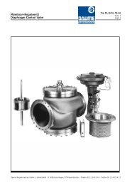
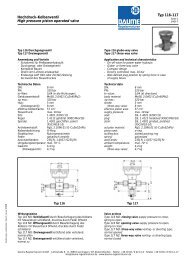
Gehäuseabmessungen DN 15 - 600, PN 6 - 320<br />
Body Dimensions DN 15 - 600, PN 6 - 320<br />
L.Nr.I<br />
<strong>Daume</strong> <strong>Regelarmaturen</strong> GmbH · Jathostrasse 8 · D-30916 Isernhagen/OT Altwarmbüchen · Telefon ++49 (0)511 / 9 02 14-0 · Telefax ++49 (0)511 / 9 02 14-17<br />
mail@daume-regelarmaturen.de · http://www.daume-regelarmaturen.de
2K-Garnitur<br />
2K-Trim<br />
(Kugelkegel für Typ 42A, 44A und 130A)<br />
(ball shaped plug for type 42A, 44A and 130A)<br />
Die "2K"-Kennlinie ergibt durch den 2stufigen Drosselsitz<br />
einen extrem niederen Anfangswert. Hierdurch beträgt das<br />
Stellverhältnis max. 1 : 100.<br />
Das hohe Stellverhältnis gestattet es, die bisher üblichen<br />
4 Kvs-Werte je Nennweite auf je 2 zu reduzieren.<br />
Kvs-Werte in Abhängigkeit von DN<br />
L.Nr. II<br />
Seite 1<br />
page 1<br />
The mentioned 2K-characteristic is showing an extremly low<br />
initial value, caused by a two-step throttling seat.<br />
Maximum range <strong>of</strong> adjustment 1 : 100.<br />
Due to this high range it is possible to reduce the normal<br />
4 different Kvs-values for each valve DN to 2 Kvs-values only.<br />
Kvs-values depending on DN<br />
<strong>Daume</strong> <strong>Regelarmaturen</strong> GmbH · Jathostrasse 8 · D-30916 Isernhagen/OT Altwarmbüchen · Telefon ++49 (0)511 / 9 02 14-0 · Telefax ++49 (0)511 / 9 02 14-17<br />
mail@daume-regelarmaturen.de · http://www.daume-regelarmaturen.de
Nomogramm 2K-Garnitur<br />
Nomograph 2K-trim<br />
kvs<br />
L.Nr. II<br />
Seite 2<br />
page 2<br />
<strong>Daume</strong> <strong>Regelarmaturen</strong> GmbH · Jathostrasse 8 · D-30916 Isernhagen/OT Altwarmbüchen · Telefon ++49 (0)511 / 9 02 14-0 · Telefax ++49 (0)511 / 9 02 14-17<br />
mail@daume-regelarmaturen.de · http://www.daume-regelarmaturen.de
Ausgabe 2-98<br />
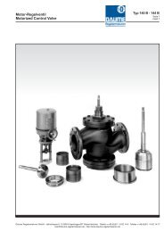
Durchflußrichtungen<br />
für Typ 34, 34A, 46, 46A, 48A, 50-3A und 50-4A<br />
Flow directions<br />
for type 34, 34A, 46, 46A, 48A, 50-3A und 50-4A<br />
Zur Auslegung von Membran-Dreiwegeventilen müssen<br />
die Anschlußart (1 bis 4) und die Wirkungsrichtung<br />
des Antriebs (1 und 2) bekannt sein. Eine entsprechende<br />
Angabe in der Bestellung vermeidet Auslegungsfehler.<br />
z.B.: Verteilerventil (3.) mit indirektem Antrieb (.2)<br />
hat die Kennzeichnung 3.2<br />
Anschlußart<br />
Mode <strong>of</strong> connection<br />
Wirkungsrichtung des Antriebs<br />
Working direction <strong>of</strong> actuator<br />
Entlüftungsventil<br />
venting valve<br />
Verteilerventil<br />
distribution valve<br />
direkt<br />
direct<br />
L.Nr. III<br />
For exact design <strong>of</strong> diaphragm 3-way valves the mode <strong>of</strong><br />
valve connection and the mode <strong>of</strong> valve action must be<br />
advised acc. to the following figures.<br />
F.i.: indication 3.2 = distribution valve (3.) with indirect<br />
actuator (.2)<br />
1. 2.<br />
Entlüftungsventil<br />
venting valve<br />
3 . 4.<br />
Mischventil<br />
mixing valve<br />
.1 .2<br />
indirekt<br />
indirect<br />
<strong>Daume</strong> <strong>Regelarmaturen</strong> GmbH · Jathostrasse 8 · D-30916 Isernhagen/OT Altwarmbüchen · Telefon ++49 (0)511 / 9 02 14-0 · Telefax ++49 (0)511 / 9 02 14-17<br />
mail@daume-regelarmaturen.de · http://www.daume-regelarmaturen.de
Ausgabe 2-98<br />
Auslegungsmethode für Regelventile<br />
Design guide lines for control valves<br />
Erforderliche technische Daten Required technical data<br />
Auslegungsdaten<br />
Druck / Temperatur, Schallpegel (max.),<br />
Abnahmevorschrift(en), Einbaulage<br />
Betriebsdaten<br />
Medium, Temperatur, Dichte, Menge max./norm./min.,<br />
Vordruck (p 1 ) max./norm./min.,<br />
Nachdruck (p 2 ) max./norm./min., Kennlinie<br />
Ventilbauart<br />
2/2-Wege Ventil, 3/2-Wege Ventil, Misch-Verteiler V.,<br />
Flanschanschluß DIN / ANSI, Einschweißenden<br />
Antriebsart<br />
Membranantrieb, Wirkungsweise, Sicherheitsstellung,<br />
Hilfsenergie verfügbar, Motorantrieb, Abschlußdruck<br />
Design data<br />
pressure / temperature, noise level (max.),<br />
test requirements, environmental position<br />
Service data<br />
medium, temperature, spec. gravity,<br />
quantity max./norm./min., upstream pressure (p 1 ) max,/<br />
norm./min., downstream pressure (p 2 ) max./norm./<br />
min., characteristic<br />
Valve body design<br />
2/2 way-valve, 3/2 way-valve, mixing-diverting v.,<br />
flange connection DIN / ANSI, welded ends<br />
Actuator system<br />
L.Nr. IV<br />
Seite 1<br />
page 1<br />
diaphragm actuator, mode <strong>of</strong> action, fail-safe position,<br />
auxillary energy-available, motor actuator,<br />
shut <strong>of</strong>f pressure<br />
<strong>Daume</strong> <strong>Regelarmaturen</strong> GmbH · Jathostrasse 8 · D-30916 Isernhagen/OT Altwarmbüchen · Telefon ++49 (0)511 / 9 02 14-0 · Telefax ++49 (0)511 / 9 02 14-17<br />
mail@daume-regelarmaturen.de · http://www.daume-regelarmaturen.de
Maximaler Betriebsdruck L.Nr. IV<br />
abhängig von der Temperatur<br />
Maximum service pressure<br />
depending on temperature<br />
Das Ventilgehäuse muß bei Betriebstemperatur dem<br />
Innendruck bzw. dem Auslegungsdruck und der Auslegungstemperatur<br />
standhalten.<br />
Außerdem muß die Festigkeit unter Prüfbedingungen<br />
beachtet werden.<br />
Die Werkst<strong>of</strong>fauswahl kann auch durch einen möglichen<br />
chemischen Angriff, Kavitation und durch hohe<br />
Durchflußgeschwindigkeit beeinflußt werden.<br />
Der höchstzulässige Betrieb- bzw. Auslegungsdruck<br />
bei Betriebs- bzw. Auslegungstemperatur kann nach<br />
folgender Formel berechnet werden:<br />
p = PN · C<br />
p = Betriebs- bzw. Auslegungsdruck<br />
PN = Druckstufe Ventilgehäuse<br />
C = Faktor (s. Tabelle)<br />
Der C-Wert berücksichtigt die Streckgrenze entspr.<br />
den Temperaturabstufungen bzw. über 500°C die Zeitstandsfestigkeit.<br />
(Lineare Interpolierung ist zulässig)<br />
Under service temperature the valve body must<br />
withstand the internal pressure resp. design pressure/<br />
design temperature and also strength test conditions.<br />
Selection <strong>of</strong> materials is also depending on possible<br />
attack by chemical action, cavitation and flow velocity.<br />
Considering the service- resp. design temperature<br />
the max. allowable service- resp. design pressure for<br />
different materials can be calculated as follows:<br />
p = PN · C<br />
p = service- resp. design pressure<br />
PN = pressure rate valve body<br />
C = reproductive factor (see table)<br />
The C-factor considers the yield strength related to<br />
temperature resp. the creep strength depending on<br />
time for temperatures higher than 5oo°C. (linear<br />
interpolation admissible)<br />
W.-Nr. Werkst<strong>of</strong>f (Auswahl) Temperatur Bereich °C Temperatur<br />
Mat.-No. material (selection) temperature range °C temperature<br />
0 - 600 -196 -60 -10 50° 120° 200° 250° 300° 350° 400° 450° 500° 520° 540° 550° 560° 580° 600°<br />
0.0625 GG-25 0 - 300 - - 1,0 1,0 1,0<br />
0.7040 GGG-40 - 350 - - 1,0 1,0 0,95 0,83 0,78 0,73 0,69<br />
1.0619 GS-C25 - 10 - 450 - - - 1,0 1,0 0,80 0,70 0,59 0,55 0,53 0,51<br />
1.7357 GS-17 CrMo55 0 - 550 - - - 1,0 1,0 1,0 1,0 0,94 0,88 0,84 0,78 0,73 0,35 0,26 0,22<br />
1.7706 GS-17 CrMoV511 0 - 550 - - - 1,0 1,0 1,0 1,0 1,0 1,0 1,0 1,0 1,0 0,57 0,45 0,39<br />
1.5415 15Mo3 0 - 530 - - - 1,0 1,0 1,0 0,96 0,86 0,78 0,73 0,69 0,61 0,34<br />
1)<br />
0,27<br />
1.7335 13CrMo44 0 - 560 - - - 1,0 1,0 1,0 1,0 0,98 0,90 0,86 0,82 0,73 0,47 0,27 0,20 0,16<br />
1.7380 10CrMo910 0 - 600 - - - 1,0 1,0 1,0 0,98 0,94 0,90 0,86 0,82 0,78 0,47 0,36 0,31 0,27 0,20 0,16<br />
1.4581 G-X7CrNiMoNb 1810 - 10 - 550 - - - 1,0 0,92 0,84 0,82 0,79 0,76 0,74 0,68 0,63 0,61 0,59 0,58<br />
2.0592 G-SoMsF45 - 10 - 250 - - - 1,0<br />
2.0966 CuAI10Ni (AB4) - 10 - 250 - - - 1,0 1,0 1,0 1.0<br />
2.1052 G-CuSn12 0 - 250 - - - 0,68 0,53 0,26 0,16<br />
2)<br />
Seite 2<br />
page 2<br />
1.4312 G-X10CrNi188 - 150 - 300 1.0 1,0 1,0 0,84 0,68 0,63 0,58<br />
1.6902 G-X6CrNi1810 - 196 1,0 1,0 1,0<br />
1) max. 530 °C Es sind geltende Regelwerke (TRD, AD,....) zu beachten.<br />
2) max. -150 °C Relevant regulations (TRD, AD,....) should be considered.<br />
<strong>Daume</strong> <strong>Regelarmaturen</strong> GmbH · Jathostrasse 8 · D-30916 Isernhagen/OT Altwarmbüchen · Telefon ++49 (0)511 / 9 02 14-0 · Telefax ++49 (0)511 / 9 02 14-17<br />
mail@daume-regelarmaturen.de · http://www.daume-regelarmaturen.de
Ausgabe 2-98<br />
Berechnung von Regelventilen<br />
Design guide lines for control valves<br />
Die Berechnung eines Regelventiles erfordert - nach den vom<br />
Betreiber mitzuteilenden Betriebsdaten - die schrittweise<br />
Beachtung der unter A) - L) aufgeführten Kriterien.<br />
A)<br />
Wirkungsweise von Membran-Regelventilen<br />
Bei der Verwendung von pneumatischen Antrieben (Membranoder<br />
Kolbenantrieb) können unterschiedliche Wirkungsweisen<br />
und Sicherheitsstellungen des Ventils erreicht werden.<br />
a) Schließventil: durch Beaufschlagung bzw. Druckerhöhung<br />
des Ventilantriebes mit Hilfsenergie schließend. Bei<br />
Druckausfall bzw. Erniedrigung durch Federkraft öffnend.<br />
b) Öffnungsventil: durch Beaufschlagung bzw. Druckerhöhung<br />
des Ventilantriebes mit Hilfsenergie öffnend.<br />
Bei Ausfall bzw. Druckerniedrigung durch Federkraft<br />
schließend.<br />
c) Dreiwegeventil: entlüftend, mischend oder verteilend entsprechend<br />
L.Nr.III, wobei die einzelnen Anschlüsse<br />
eine entsprechende Wirkungsweise ergeben.<br />
Bei beidseitig beaufschlagten Membran- oder Kolbenventilen<br />
kann die Wirkungsweise des ventils durch einfaches Umwechseln<br />
der Hilfsenergie-Anschlüsse geändert werden.<br />
Entsprechend den Sicherheitsbestimmungen und dem<br />
betrieblichen Anlageverfahren ist die Ventil-"Sicherheitsstellung",<br />
d.h. die Stellung bei Ausfall der Hilfsenergie zu<br />
beachten.<br />
Beidseitig beaufschlagte Antriebe können keine eindeutige,<br />
bestimmbare Stellung bei Hilfsenergieausfall einnehmen.<br />
B)<br />
Durchflußmenge in Volumen (Q) oder Gewicht (G)<br />
Man geht zunächst von der Menge aus, die normalen Betriebsbedingungen<br />
entspricht (Q oderG). Um Kapazitätserweiterungen<br />
oder Laständerungen zu ermöglichen, wird in der<br />
Regel das Ventil so bemessen, daß die normale Menge<br />
bei 70% (linear) bis 85% (gleichprozentig) des Hubes erreicht<br />
wird, d.h. die max. Menge (Q max oder G max ) ist um ca.<br />
30% größer einzusetzen als Q oder G.<br />
Umrechnung Q =<br />
G<br />
bzw. G = Q ·<br />
o<br />
o<br />
Volumen Q (m3 /h)<br />
Gewicht G (t/h)<br />
Dichte (t/m3 o )<br />
L.Nr. IV<br />
Seite 3<br />
page 3<br />
The calculation <strong>of</strong> a control valve requires the stepwise<br />
consideration <strong>of</strong> the criteria listed under A) - L) based on the<br />
operational data supplied by the user.<br />
A)<br />
Mode <strong>of</strong> operation <strong>of</strong> diaphragm control valves<br />
Various modes <strong>of</strong> operatios and safety positions <strong>of</strong> the<br />
valve may be obtained by utilizing pneumatic actuators<br />
(diaphragm or piston type).<br />
a) Shut <strong>of</strong>f valva:closes by applying or increasing auxilary<br />
pressure. In case <strong>of</strong> pressure loss or reduction the valve<br />
will be opened by spring.<br />
b) Opening valve: opens by applying or increasing auxilary<br />
pressure. In case <strong>of</strong> pressure loss or reduction the valve<br />
will be closed by spring.<br />
c) 3-way valve: venting, mixing or distributing according<br />
to L.Nr. III. Mode <strong>of</strong> operation determinded by choice <strong>of</strong><br />
equivalent connection.<br />
The mode <strong>of</strong> operation <strong>of</strong> diaphragm or piston operated<br />
valves with an auxilary pressure inlet on both sides may<br />
easily be inverted by changing the air inlets.<br />
According to the safety regulations and the inplant<br />
procedures the "fail safe position" <strong>of</strong> the valve (in case <strong>of</strong><br />
loss <strong>of</strong> auxilary pressure) must be taken in consideration.<br />
Valves with a pressure inlet on both sides do not have a<br />
defined position in case <strong>of</strong> auxilary pressure loss<br />
B)<br />
Flow by volume (Q) or weight (G)<br />
Based on the quantity <strong>of</strong> normal operation the valve will be<br />
calculated for load variations and capacity expansions in<br />
such manner that the normal flow will be achieved at<br />
70% (linear) until 85% (uniform percentage) <strong>of</strong> the total<br />
troke. This means the max. quantity (Q max /G max ) has to be<br />
calculated approximately 30% higher than Q or G.<br />
G<br />
Conversion Q = o resp. G = Q · o<br />
Volume Q (m3 /h)<br />
Weight G (t/h)<br />
Density (t/m3 o<br />
)<br />
<strong>Daume</strong> <strong>Regelarmaturen</strong> GmbH · Jathostrasse 8 · D-30916 Isernhagen/OT Altwarmbüchen · Telefon ++49 (0)511 / 9 02 14-0 · Telefax ++49 (0)511 / 9 02 14-17<br />
mail@daume-regelarmaturen.de · http://www.daume-regelarmaturen.de
Berechnung von Regelventilen<br />
Design guide lines for control valves<br />
C)<br />
Druckabfall Ð p (Differenzdruck)<br />
Bei einem Regelventil sollte der Druckabfall nicht als<br />
Verlust (und darum möglichst gering zu halten) angesehen<br />
werden. Eine gute Regelung bedarf vielmehr eines angemessenen<br />
Druckabfalles, der bewußt bei der Anlagenplanung<br />
eingerechnet werden muß. Der zur Regelung<br />
zur Verfügung stehende Druckabfall sollte ca 30% der<br />
gesamten Verluste des Systems (einschließlich Regelventil)<br />
ausmachen oder 50% des Druckabfalles im übrigen System<br />
(ohne Regelventil). Andererseits darf der vorhandene Druckabfall<br />
bei geschlossenem Ventil den max. Differenzdruck,<br />
bei dem das Ventil noch arbeitet, nicht überschreiten. Bei<br />
hohen Differenzdrücken sind mehrstufige Einsitzventile<br />
vorzusehen.<br />
D)<br />
K v -Wert<br />
Definition:<br />
Der Kv-Wert gibt an, wieviel m o<br />
3 /h Wasser ( = 1.0 t/m3 ) bei<br />
einem Differenzdruck (Ðp ) von 1 bar bei Raumtemperatur<br />
bei jeweiligen Hub durch ein Ventil fließen.<br />
Der K v -Wert ist also eine unmittelbare positive Aussage über<br />
die Leistungsfähigkeit des Ventils; im Gegensatz dazu kann<br />
der z-Wert nur mit Angabe der Nennweite zu einer Berechnung<br />
herangezogen werden.<br />
Der wirkliche K v -Wert beim Nennhub wird K v 100 genannt. Der<br />
K vs -Wert dagegen ist der vorgesehene K v -Wert einer Bauserie<br />
bei 100% Hub. Der K v 100 -Wert darf VDI/VDE-Richtlinien<br />
2173 max. ± 10% vom K vs -Wert abweichen.<br />
In Tab. 2 sind die K vs -Werte aufgeführt. Sie gelten für alle<br />
Regelventilbauarten. Jede Ventilnennweite (DN) kann mit<br />
verschiedenen K vs -Werten geliefert werden.<br />
Zur Regelung kleiner Durchflußmengen sind Kleinstflußventile<br />
mit Flanschenanschluß DN 15 - 32 lieferbar<br />
(K vs -Werte s. Tab.3).<br />
C)<br />
Pressure drop Ð p (differential pressure)<br />
L.Nr. IV<br />
Seite 4<br />
page 4<br />
The pressure drop <strong>of</strong> a control valve should not be considered<br />
as loss (and therefore kept to a minimum), because a good<br />
regulation requires a certain pressure drop which should<br />
be calculated during equipment / facility design. The pressure<br />
drop available for regulation should be appr. 30% <strong>of</strong> the<br />
total loss within the system (including the conrol valve itself)<br />
or 50% <strong>of</strong> the pressure drop in the remaining system with<br />
the control valve excluded. Otherwise the differential pressure<br />
must not exceed the max. differential pressure at which<br />
the valve is still operating. In case <strong>of</strong> high differential pressures<br />
multi step single seat valves should be considered.<br />
D)<br />
K v -Value<br />
Definition:<br />
The Kv-value indicates how many m o<br />
3 /h water ( = 1.0 t/m3 )<br />
under a differential pressure <strong>of</strong> 1 bar at room temp. will<br />
flow through the valve at respective stroke.<br />
Therefore the K v -value is a direct positive indicator concerning<br />
the performance <strong>of</strong> the valve. Contrary to that the z-value can<br />
be used for calculation only in connection with the diameter<br />
<strong>of</strong> the valve.<br />
The actual K v -value at nominal stroke is called K v 100 . The<br />
K vs -value is defined as the planned K v -value <strong>of</strong> a certain<br />
series production at 100% stroke. According to VDI / VDE<br />
regulations 2173 the K v 100 -value may differ ± 10% from the<br />
K vs -value.<br />
Table 2 shows the K vs -values. They are valid for all types <strong>of</strong><br />
control valves. Any valve diameter (DN) may be supplied<br />
with various K vs -values.<br />
For controlling low flow quantities minimum flow valves are<br />
available with flanges DN 15 - 32 (K vs -values at tab. 3).<br />
<strong>Daume</strong> <strong>Regelarmaturen</strong> GmbH · Jathostrasse 8 · D-30916 Isernhagen/OT Altwarmbüchen · Telefon ++49 (0)511 / 9 02 14-0 · Telefax ++49 (0)511 / 9 02 14-17<br />
mail@daume-regelarmaturen.de · http://www.daume-regelarmaturen.de
Ausgabe 2-98<br />
Berechnung von Regelventilen<br />
Design guide lines for control valves<br />
E)<br />
Kennlinien<br />
Bei der Auswahl des Regelventils ist es nötig, den Verlauf der<br />
Durchflußcharakteristik über den ganzen Hub zu kennen,<br />
nämich die Kennlinie.<br />
Es stehen zwei Arten von Kennlinien zur Verfügung.<br />
a) Lineare Kennlinie (Nomogramm 1): der K v -Wert ist dem<br />
Hub proportional, d.h. bei 30% Hub ist der K v -Wert<br />
30% von K vs .<br />
b) Gleichprozentige Kennlinie (Nomogramm 2): eine Änderung<br />
des Hubes um eine Hubeinheit bewirkt eine Änderung des<br />
K v -Wertes, die dem K v -Wert vor der Änderung proportional<br />
ist. D.h. eine bestimmte Hubänderung bewirkt bei<br />
kleinem k v -Wert eine kleine Änderung, bei großem<br />
K v -Wert eine große Änderung des Durchflusses.<br />
Die erreichte Kennlinienneigung darf lt. VDI/VDE-Richtlinien<br />
2173 im Bereich von 10 - 100% Hub eine max. Abweichung von<br />
± 30% von der Kennlinienneigung der Grundform haben.<br />
Vor Auswahl der Ventilkennlinie muß zunächst einmal die<br />
Kennlinie der Regelstrecke (Anlage) bekannt sein.<br />
Als Regel gilt, daß eine logarithmische Übergangsfunktion der<br />
Regelstrecke eine gleichprozentige Kennlinie des Ventils erfordert.<br />
Dagegen erfordert eine Regelstrecke mit konstantem Anlaufwert<br />
oder Ausgleichsgrad eine lineare Kennlinie.<br />
Außerdem ist zu analysieren, welche Einflüsse die Hauptgrößen<br />
und Laständerungen auf den Energiestrom durch das Ventil<br />
haben. Allgemein kann man sagen, daß dann ein Ventil mit<br />
gleichprozentiger Kennlinie verwendet werden soll, wenn zur<br />
Aufrechterhaltung einer bestimmten Durchflußmenge<br />
verschiedene Ventilstellungen erforderlich sind oder wenn die<br />
Hauptstörgrößen die Durchflußmenge bei konstantem Hub<br />
verändern (z.B. Vordruckschwankung) (s.a. DIN 19226).<br />
Die Auswahl einer Kennlinie kann auch dadurch bestimmt sein,<br />
daß die Anlage mit 2 Mengen bei jeweils bestimmten Hüben<br />
und Druckverhältnissen gefahren werden soll. Beim Einzeichnen<br />
der errechneten K v -Werte über den entsprechenden Hüben<br />
in die Nomogramme 1 und 2 wird sich eine Kennlinie als die<br />
geeignetere erweisen.<br />
E)<br />
Characteristics<br />
L.Nr. IV<br />
When selecting the appropriate control valves it is<br />
mandatory to know the flow characteristic over the entire<br />
stroke = characteristic.<br />
Two types <strong>of</strong> characteristics are available.<br />
a) Linear characteristic (nomograph 1): K v -value proportional<br />
to the stroke (i.e. at 30% stroke the K v -value is<br />
30% <strong>of</strong> K vs .<br />
Seite 5<br />
page 5<br />
b) Uniform percentage characteristic (nomograph 2):<br />
changing the stroke by a certain amount results in a<br />
change proportional change <strong>of</strong> the K v -value. That is that<br />
a certain change <strong>of</strong> stroke results in a small change <strong>of</strong><br />
flow at low K v -value and a large change at high K v -value.<br />
According to VDI / VDE directive 2173 the slope <strong>of</strong> the<br />
characteristic may not axceed a deviation <strong>of</strong> ± 30% <strong>of</strong> the<br />
slope <strong>of</strong> the basic characteristic within the stroke range <strong>of</strong><br />
10 - 100%.<br />
Before selecting the valve characteristic the characteristic<br />
<strong>of</strong> the entire controlled system must be known. Ground rule:<br />
a logarithmic transient response <strong>of</strong> the controlled system<br />
requires a valve with a uniform percentage characteristic<br />
whereas a controlled system with constant reaction value<br />
or gain factor requires a linear valve characteristic.<br />
Futhermore the influence <strong>of</strong> the major factors and load<br />
variations on the flow through the valve must be analyzed.<br />
In general one can say that a valve with a uniform<br />
percentage characteristic should be used if it becomes<br />
necessary to maintain a certain flow with various valve<br />
positions or if the main disturbance factors will vary the flow<br />
at a given stroke (i.e. variations <strong>of</strong> prim. pressure)<br />
(DIN 19226).<br />
The selection <strong>of</strong> characteristic can be obtained by operating<br />
the equipment with two different quantities at certain strokes<br />
and pressures. When plotting the calculated K v -values over<br />
the corresponding strokes (nomograph 1 & 2) one<br />
characteristic will be found suitable.<br />
<strong>Daume</strong> <strong>Regelarmaturen</strong> GmbH · Jathostrasse 8 · D-30916 Isernhagen/OT Altwarmbüchen · Telefon ++49 (0)511 / 9 02 14-0 · Telefax ++49 (0)511 / 9 02 14-17<br />
mail@daume-regelarmaturen.de · http://www.daume-regelarmaturen.de
Berechnung von Regelventilen<br />
Design guide lines for control valves<br />
L.Nr. IV<br />
Seite 6<br />
page 6<br />
<strong>Daume</strong> <strong>Regelarmaturen</strong> GmbH · Jathostrasse 8 · D-30916 Isernhagen/OT Altwarmbüchen · Telefon ++49 (0)511 / 9 02 14-0 · Telefax ++49 (0)511 / 9 02 14-17<br />
mail@daume-regelarmaturen.de · http://www.daume-regelarmaturen.de
Ausgabe 2-98<br />
Berechnung von Regelventilen<br />
Design guide lines for control valves<br />
L.Nr. IV<br />
Seite 7<br />
page 7<br />
<strong>Daume</strong> <strong>Regelarmaturen</strong> GmbH · Jathostrasse 8 · D-30916 Isernhagen/OT Altwarmbüchen · Telefon ++49 (0)511 / 9 02 14-0 · Telefax ++49 (0)511 / 9 02 14-17<br />
mail@daume-regelarmaturen.de · http://www.daume-regelarmaturen.de
Berechnung von Regelventilen<br />
Design guide lines for control valves<br />
F)<br />
Stellverhältnis<br />
Der kleinste Kv-Wert, bei dem die unter E) genannte<br />
Neigungstoleranz noch eingehalten wird, heißt Kvr . Dieser Wert<br />
liegt zwischen 0 - 10% Hub. Das wirklich erreichte Stellverhältnis<br />
Kvs<br />
Kvs<br />
Kvr Kvo<br />
ist definiert als . Das theoretische Stellverhältnis ( ) ist bei<br />
<strong>Daume</strong>-Ventilen (falls nicht ausdrücklich anders gewünscht)<br />
bei linearer und gleichprozentiger Kennlinie 33:1.<br />
Eine Ausnahme bilden <strong>Daume</strong>-Regelventile mit "2K-Kennlinie"<br />
und einem Stellverhältnis von 150:1.<br />
Ausführliche Beschreibung siehe Liste Nr. V.<br />
Das wirklich erreichte Stellverhältnis darf das theoretische<br />
Stellverhältnis um höchstens 10% unterschreiten.<br />
G)<br />
Berechnung der Ventil-Nennweite (DN) und<br />
Geschwindigkeit (W)<br />
Unter Berücksichtigung der empfohlenen Durchflußgeschwindigkeiten<br />
werden die Ventil-Nennweite und Geschwindigkeit<br />
nach folgenden Formeln berrechnet:<br />
Empfohlene Geschwindigkeiten für unterschiedliche Medien<br />
siehe Liste Nr. VII.<br />
H)<br />
Berechnung des Ventil-Nenndrucks (PN)<br />
Auszug aus DIN 2401<br />
F)<br />
Control ratio<br />
L.Nr. IV<br />
Seite 8<br />
page 8<br />
The lowest Kv-value at which the slope tolerance (E) is still<br />
being met is the Kvr . This value is between 0 - 10% <strong>of</strong> the<br />
Kvs<br />
stroke. The actual control ratio is defined as Kvr . The<br />
Kvs<br />
theoretical control ratio ( Kvo ) <strong>of</strong> our valves is 33 : 1 at linear<br />
and uniform percentage characteristic (if not ordered otherwise).<br />
An excemption to the above are <strong>Daume</strong> control valves with<br />
a "2K-characteristic" and a control ratio <strong>of</strong> 150 : 1.<br />
For detailed description please see table no. V.<br />
The resulting control ratio should not fall below 10% the<br />
theoretical control ratio.<br />
G)<br />
Calculation <strong>of</strong> valve diameter (DN) and<br />
flow velocity (W)<br />
Considering the recommended flow velocity the valve diameter<br />
and flow velocity will be calculated according to the formulas<br />
below:<br />
Recommended flow velocities for various media:<br />
please see table no. VII.<br />
H)<br />
Calculation <strong>of</strong> nominal pressure (PN) <strong>of</strong> the valve<br />
Excerpt <strong>of</strong> DIN 2401<br />
<strong>Daume</strong> <strong>Regelarmaturen</strong> GmbH · Jathostrasse 8 · D-30916 Isernhagen/OT Altwarmbüchen · Telefon ++49 (0)511 / 9 02 14-0 · Telefax ++49 (0)511 / 9 02 14-17<br />
mail@daume-regelarmaturen.de · http://www.daume-regelarmaturen.de
Berechnung von Regelventilen<br />
Design guide lines for control valves<br />
I)<br />
K v -Wert-Berechnung<br />
Tabelle 1<br />
*Wenn die Zähigkeit des Durchflußmediums größer ist als 3°E<br />
oder 20 cSt, muß der K v -Wert korrigiert werden (s. Abschnitt K)<br />
Bezeichnungen und Einheiten:<br />
K v<br />
Durchflußkoeffizient bei Ðp = 1 bar,<br />
= 1,0 (t/m3 Q (m<br />
), t = 20°C<br />
3 /h) Volumendurchfluß von Flüssigkeiten<br />
QN (Nm3 /h) Volumendurchfluß von Gasen im<br />
Normzustand (1,013 bar, 0°C)<br />
G (kg/h) Gewichtsdurchfluß von Dampf<br />
GS p1 p2 Ðp<br />
(kg/h)<br />
(bar)<br />
(bar)<br />
(bar)<br />
(t/m<br />
Gewichtsdurchfluß von Sattdampf<br />
absoluter Vordruck (Eingang)<br />
absoluter Abströmdruck (Ausgang)<br />
Druckdifferenz im Ventil (p1 - p2 )<br />
3 ) Dichte von Flüssigkeiten<br />
N (kg/Nm3 ) Dichte von Gasen im Normzustand<br />
(1,013 bar, 0°C)<br />
v2 (m3 o<br />
o<br />
o<br />
T<br />
/kg)<br />
(°K = 273 + t°C)<br />
spez. Dampfvolumen bei p2 *<br />
absolute Temperatur im Ventil<br />
V (°E) (cSt) Viskosität<br />
*lt. Dampftafel<br />
I)<br />
Calculation <strong>of</strong> the K v -value<br />
Table 1<br />
L.Nr. IV<br />
Seite 9<br />
page 9<br />
*In case the viscosity <strong>of</strong> the medium is higher than 3°E or<br />
20 cSt the K v -value should be corrected (see paragraph K)<br />
description and units <strong>of</strong> measure:<br />
flow coefficient at Ðp = 1 bar,<br />
= 1.0 (t/m3 o ), t = 20°C<br />
flow (volume) <strong>of</strong> liquids<br />
flow (volume) <strong>of</strong> gases at standard condition<br />
(1.013 bar, 0°C)<br />
flow (weight) <strong>of</strong> steam<br />
flow (weight) <strong>of</strong> saturated steam<br />
primary pressure absolute (inlet)<br />
secondary pressure absolute (outlet)<br />
pressure difference in the valve (p1 - p2 )<br />
density <strong>of</strong> liquids<br />
density <strong>of</strong> gases at standard condition (1.013 bar, 0°C)<br />
specific volume <strong>of</strong> steam at p 2 *<br />
temperature absolute in the valve<br />
viscosity<br />
*accord. to steam table<br />
<strong>Daume</strong> <strong>Regelarmaturen</strong> GmbH · Jathostrasse 8 · D-30916 Isernhagen/OT Altwarmbüchen · Telefon ++49 (0)511 / 9 02 14-0 · Telefax ++49 (0)511 / 9 02 14-17<br />
mail@daume-regelarmaturen.de · http://www.daume-regelarmaturen.de
Berechnung von Regelventilen<br />
Design guide lines for control valves<br />
J)<br />
Berechneter K v -Wert und Auswahl des K vs -Wertes<br />
Die in der Tabelle angegebenen Zahlen sind K vs -Werte, die<br />
für 100% Hub gelten. Sie sind für alle Ausführungsformen der<br />
Ventilgehäuse (Einsitz- und Dreiwegeventil) maßgebend. Für<br />
jede DN sind mindestens 4 verschiedene Standard K vs -Werte<br />
wählbar. Kleinere K vs -Werte je DN und K vs -Zwischenwerte<br />
sind möglich.<br />
Tabelle 2<br />
K vs -Werte für Micro- und Kleinstflußventile<br />
Zur Regelung kleiner Durchflußmengen sind Micro- und Kleinstflußventile<br />
mit Flanschanschluß DN 15 - 32 vorgesehen. Jede<br />
dieser Ventil DN kann mit jedem in der Tabelle 3 angegebenen<br />
K vs -Wert geliefert werden.<br />
Tabelle 3<br />
K)<br />
K v -Wert Korrektur für zähflüssige Medien<br />
Die Viskosität einer Flüssigkeit kann bis zu 3°E oder 20 cSt<br />
unberücksichtigt bleiben. Darüberhinaus ist wie folgt zu<br />
korrigieren: Der nicht korrigierte K v -Wert wird mit K vz bezeichnet.<br />
Die Zähigkeitszahl Z wird nach folgender Formel berechnet:<br />
Eine Umrechnung von °E in cSt erfolgt nach der Formel (zulässig<br />
für Werte > 3°E):<br />
Mit Hilfe von Z kann aus dem nomogramm 3 der Korrekturfaktor<br />
K bestimmt werden, mit dem der zuvor berechnete<br />
K vz multipliziert wird.<br />
J)<br />
Calculated K v -value and selection <strong>of</strong> K vs -value<br />
L.Nr. IV<br />
Seite 10<br />
page 10<br />
Figure shown in the table below are K vs -values valid at<br />
100% stroke. They are relevant for all valve bodies and types<br />
(single seat and 3-way valve). Within each DN at least 4<br />
different standard K vs -values are selectable. Lower K vs -values<br />
per DN and K vs -interpolation are feasible.<br />
Table 2<br />
K vs -values for micro- and minimum flow valves<br />
For controlling <strong>of</strong> small flows micro- and minimum flow valves<br />
with flanges DN 15 - 32 are available. Each <strong>of</strong> this valves may<br />
be supplied with each <strong>of</strong> the K vs -values shown in the table<br />
below.<br />
Table 3<br />
K)<br />
K v -value correction for high viscosity medium<br />
The viscosity <strong>of</strong> liquid below 3°E or 20 cSt does not need to<br />
be considered. For higher vicosities the following correction<br />
formulas should be applied: the uncorrected K v -value is<br />
expressed as K vz .<br />
The viscosity coefficient (Z) may be calculated by using the<br />
formula below:<br />
To convert from °E into cSt use the formula below<br />
(permissible for values > 3°E):<br />
By using "Z" the correction factor "K" may be taken from<br />
nomograph 3. The earlier calculated K vz will be multiplied<br />
with "K".<br />
<strong>Daume</strong> <strong>Regelarmaturen</strong> GmbH · Jathostrasse 8 · D-30916 Isernhagen/OT Altwarmbüchen · Telefon ++49 (0)511 / 9 02 14-0 · Telefax ++49 (0)511 / 9 02 14-17<br />
mail@daume-regelarmaturen.de · http://www.daume-regelarmaturen.de
Berechnung von Regelventilen<br />
Design guide lines for control valves<br />
Nomogramm 3<br />
Beispiel:<br />
Medium: Melasse, zähflüssig<br />
Menge (Q): 3,0 m3 /h<br />
Temperatur (t): 40° C<br />
Differenzdruck (Ðp):<br />
Dichte ( ):<br />
0,5 bar<br />
1,25 t/m3 o<br />
Viskosität (V): 140°E<br />
Lt. Nomogramm 3 beträgt der Korrekturfaktor K » 2,0,<br />
mit dem der K vz -Wert 4,74 multipliziert wird.<br />
Der korrigierte K v -Wert ist nun 9,48.<br />
Zu wählen K vs4 = 10,0 DN 25, W = 1,7 m/s.<br />
Zähigkeitszahl Z<br />
Viscosity coefficient<br />
Example:<br />
medium: molasses (viscous)<br />
quantity (Q): 3.0 m3 /h<br />
temperature (t): 40° C<br />
differential pressure (Ðp): 0.5 bar<br />
density ( ): 1.25 t/m3 o<br />
vicosity ( V): 140°E<br />
according to the nomograph the correction factor<br />
K = 2.0 which is multiplied with K vz -value <strong>of</strong> 4.74.<br />
The corrected K v -value now reads 9.58.<br />
Select: K vs4 = 10.0 DN 25, W = 1.7m/s.<br />
L.Nr. IV<br />
Seite 11<br />
page 11<br />
<strong>Daume</strong> <strong>Regelarmaturen</strong> GmbH · Jathostrasse 8 · D-30916 Isernhagen/OT Altwarmbüchen · Telefon ++49 (0)511 / 9 02 14-0 · Telefax ++49 (0)511 / 9 02 14-17<br />
mail@daume-regelarmaturen.de · http://www.daume-regelarmaturen.de
Berechnung von Regelventilen<br />
Design guide lines for control valves<br />
L)<br />
Verdampfung von Flüssigkeiten im Ventil<br />
Eine Verdampfung im Ventil tritt auf, wenn durch den Druckabfall<br />
(Ðp) der Betriebsdruck des Mediums auf oder unter den<br />
Verdampfungsdruck (P v ) reduziert wird, der der Temperatur des<br />
Mediums entspricht.<br />
Man muß daher bei der Berechnung des Ventils von der<br />
Überlegung ausgehen, den Druckabfall in zulässigen Grenzen<br />
zu halten. Der zulässige Druckabfall (Ðp krit ) bei möglicher Verdampfung<br />
wird wie folgt berechnet:<br />
Ðp krit = p 1 - p v<br />
Der Wert Ðp krit ist in die K v -Berechnungsformel einzusetzen.<br />
Der K vs -Wert wird dabei größer ausfallen als unter normalen<br />
Bedingungen.<br />
Weiterhin muß beachtet werden, daß der Verdampfungsdruck<br />
auch bei Kleinstflußbedingungen nicht unterschritten wird.<br />
Die Regelbarkeit der Anlage wird durch eine evtl. auftretende<br />
Verdampfung erheblich gemindert. Auch ein Ventil mit größerem<br />
K vs -Wert kann die Forderung einer besseren Regelbarkeit nicht<br />
erfüllen. Eine entsprechende Grundmengeneinstellung (min.<br />
erreichbarer K v -Wert) bietet eine Sicherheit gegen zu großen<br />
Druckabfall und damit eine Verdampfung.<br />
Beispiel:<br />
Medium = Wasser<br />
Q = 53,0 m3 /h<br />
t = 96° C ( = 0,960 t/m3 o<br />
)<br />
P1 P2 Ðp<br />
= 2,5 bar a<br />
= 0,7 bar a<br />
= 1,8 bar<br />
Pv = 0,9 bar a (entsprechend » 96° C lt. Dampftafel)<br />
= 2,5 (P1 ) - 0,9 (Pv ) = 1,6 bar max.<br />
Ðp krit<br />
L)<br />
Evaporation <strong>of</strong> fluids in the valve<br />
0,960<br />
Kv-Wert = 53 · = 41,05, gewählt K<br />
1,6<br />
vs3 = 63, DN 80, W = 2,92 m/s<br />
Kv-value selected<br />
Berechnung des Kv-Wertes ohne Berücksichtigung der Verdampfung<br />
calculation <strong>of</strong> the Kv-value w/o cosidering evaporation<br />
0,960<br />
Kv-Wert = 53 · = 38,7, gewählt Kvs2 = 40, DN 80, W = 2,92 m/s<br />
K<br />
1,8<br />
v-value selected<br />
L.Nr. IV<br />
Seite 12<br />
page 12<br />
Evaporation in the valve occurs in cases when the pressure<br />
drop (Ðp) causes the operating pressure to fall to or below<br />
the evaporation pressure which corresponds with the<br />
temperature <strong>of</strong> the medium.<br />
Therefore the pressure drop should be kept within permissible<br />
limits during calculation <strong>of</strong> the valve. In case <strong>of</strong> potential<br />
evaporation the permissible pressure drop (Ðp crit ) may be<br />
calculated as follows:<br />
Ðp crit = p 1 - p v<br />
The term Ðpcrit should be inserted in the Kv-formula. In this case the Kvs-value will be higher compared to<br />
normal conditions.<br />
At minimum flow the evaporation pressure should not be<br />
kept within its limits. Controlling <strong>of</strong> the entire system is<br />
considerably reduced by potential evaporation. Even<br />
a valve with a higher K vs -value will not improve the<br />
regulation. An adequate basic quantity adjustment (min.<br />
achievable K v -value) provides sufficient margin to avoid<br />
to high pressure drop and therefore evaporation.<br />
Example:<br />
medium = water<br />
Q = 53.0 m3 /h<br />
t = 96° C ( = 0.960 t/m3 o<br />
)<br />
P1 P2 Ðp<br />
= 2.5 bar a<br />
= 0.7 bar a<br />
= 1.8 bar<br />
Pv = 0.9 bar a » 96° C acc. to steam table<br />
= 2.5 (P1 ) - 0.9 (Pv ) = 1.6 bar max.<br />
<strong>Daume</strong> <strong>Regelarmaturen</strong> GmbH · Jathostrasse 8 · D-30916 Isernhagen/OT Altwarmbüchen · Telefon ++49 (0)511 / 9 02 14-0 · Telefax ++49 (0)511 / 9 02 14-17<br />
mail@daume-regelarmaturen.de · http://www.daume-regelarmaturen.de<br />
Ðp crit
Ausgabe 2-98<br />
Kegelausführungen<br />
Cone types<br />
L.Nr.V<br />
Seite 1<br />
page 2<br />
<strong>Daume</strong> <strong>Regelarmaturen</strong> GmbH · Jathostrasse 8 · D-30916 Isernhagen/OT Altwarmbüchen · Telefon ++49 (0)511 / 9 02 14-0 · Telefax ++49 (0)511 / 9 02 14-17<br />
mail@daume-regelarmaturen.de · http://www.daume-regelarmaturen.de
Kegelausführungen<br />
Cone types<br />
L.Nr.V<br />
Seite 2<br />
page 2<br />
<strong>Daume</strong> <strong>Regelarmaturen</strong> GmbH · Jathostrasse 8 · D-30916 Isernhagen/OT Altwarmbüchen · Telefon ++49 (0)511 / 9 02 14-0 · Telefax ++49 (0)511 / 9 02 14-17<br />
mail@daume-regelarmaturen.de · http://www.daume-regelarmaturen.de
Abnahme- und Prüfvorschriften<br />
Acceptance- and inspection specifications<br />
Für die Herstellung und Prüfung von DAUME-Armaturen<br />
können die nachfolgend aufgeführten Regelwerke angewendet<br />
werden.<br />
Vorschrift Code<br />
TRD<br />
Technische Regeln für Dampfkessel<br />
Zutreffend für:<br />
Armaturen, die zur Wandung des Dampfkessels gehören<br />
(TRD 110, 1), das sind die ersten Absperrorgane in den<br />
Dampf-, Speise- und Entleerungsleitungen (TRD 401, 2.7)<br />
VGB<br />
Richtlinien für den Bau und die Bestellung von<br />
Heißdampfrohrleitungen und Speisewasserdruckleitungen<br />
Zutreffend für:<br />
Armaturen für Heißdampfrohrleitungen mit<br />
Dampftemperaturen von mehr als 400°C und für Speisewasserdruckleitungen.<br />
Diese Vorschrift kann auch sinngemäß<br />
für geringere Dampftemperaturen angewendet werden.<br />
DIN 2470<br />
Gasleitungen aus Stahlrohren<br />
Zutreffend für:<br />
Armaturen in Stahlleitungen, die zum Transport von<br />
brennbaren verdichteten Gasen dienen.<br />
DIN 25418<br />
Kerntechnische Anlagen<br />
Armaturen<br />
Zutreffend für:<br />
Armaturen für kerntechnische Anlagen, Festlegung der<br />
Anforderungsstufen.<br />
UVV 44<br />
Sauerst<strong>of</strong>f<br />
SEB 384030-69<br />
Stahl-Eisen-Betriebsblatt<br />
Zutreffend für:<br />
Armaturen für Sauerst<strong>of</strong>fanlagen, insbesondere für Sauerst<strong>of</strong>f<br />
verwendbare Werkst<strong>of</strong>fe und Schmiermittel, die durch die<br />
Bundesanstalt für Materialprüfung (BAM) zugelassen sind.<br />
VDI/VDE 2173<br />
Strömungstechnische Kenngrößen von Stellventilen und<br />
deren Bestimmung<br />
Zutreffend für:<br />
Ergänzende Bestimmungen für Stellventile, Definition und<br />
Prüfung von Kennlinien, Kv-Werten und Stellverhältnis.<br />
VDI/VDE 2174<br />
Mechanische Kenngrößen von Stellventilen für strömende<br />
St<strong>of</strong>fe und deren Bestimmung<br />
Zutreffend für:<br />
Ergänzende Bestimmungen für Stellventile, Prüfung der<br />
Stellantriebe und Leckraten für Regelventile.<br />
Alle Armaturen können auch nach Werkvorschriften und nach<br />
ausländischen Abnahmespezifikationen geprüft werden.<br />
The following regulations may apply to the production and<br />
testing <strong>of</strong> DAUME-armatures.<br />
TRD<br />
Technical regulations for steam boilers<br />
L.Nr. VI<br />
Applicable to:<br />
Armatures belonging to the wall <strong>of</strong> a steam boiler (TRD<br />
110, 1) such as first shut <strong>of</strong>f devices within steam-, feederand<br />
drain pipes (TRD 401, 2.7).<br />
VGB<br />
Regulations for the manufacturing and ordering <strong>of</strong> pipes for<br />
superheated steam and feedwater pressure pipes<br />
Applicable to:<br />
Armatures in superheated steam pipes with steam<br />
temperatures above 400°C and pressurized feedwater pipes.<br />
This regulation may logically be applied at lower steam<br />
temperatures also.<br />
DIN 2470<br />
Gas pipes (steel)<br />
Applicable to:<br />
Armatures within steel pipes used to transport flammable<br />
pressurized gases.<br />
DIN 25418<br />
Nuclear equipment<br />
armatures<br />
Applicable to:<br />
Armatures <strong>of</strong> nuclear installations, definition <strong>of</strong><br />
demand level.<br />
UVV 44<br />
Oxygen<br />
SEB 384030-69<br />
Steel / iron-operating sheet<br />
Applicable to:<br />
Armatures <strong>of</strong> oxygen equipment particularly for material and<br />
lubrication approved by the "Bundesanstalt für Materialprüfung"<br />
(BAM - Federal Agency for Material Testing and Approval).<br />
VDI/VDE 2173<br />
Flow technical characteristics <strong>of</strong> control valves and<br />
their definitions<br />
Applicable to:<br />
Supplemental regulations for control valves. Definition and<br />
vertification <strong>of</strong> characteristics, Kv-value and control ratio.<br />
VDI/VDE 2174<br />
Mechanical characteristics <strong>of</strong> control valves for flowing<br />
media and their definition<br />
Applicable to:<br />
Supplemental regulations for control valves.<br />
Testing <strong>of</strong> actuators and leakage rates <strong>of</strong> control valves.<br />
All armatures may also be tested according to customized<br />
standards and/or foreign acceptance specifications.<br />
<strong>Daume</strong> <strong>Regelarmaturen</strong> GmbH · Jathostrasse 8 · D-30916 Isernhagen/OT Altwarmbüchen · Telefon ++49 (0)511 / 9 02 14-0 · Telefax ++49 (0)511 / 9 02 14-17<br />
mail@daume-regelarmaturen.de · http://www.daume-regelarmaturen.de
Ausgabe 2-98<br />
Auswahlkriterien für Ventilbauart und Regelkegel<br />
Selection criteria <strong>of</strong> valve body design and control cone<br />
Legende<br />
Kegelform<br />
2K Zweistufenkegel<br />
PA Parabolkegel<br />
PAm Parabolkegel, mehrstufig<br />
LO Lochkegel<br />
LKm Lochkörbe, mehrstufig<br />
Ventilbauart<br />
+ bevorzugt zu verwenden<br />
O verwendbar<br />
- nicht verwendbar<br />
p 1 Vordruck<br />
p 2 Nachdruck<br />
DN e DN-Eingang<br />
DN a DN-Ausgang<br />
W a Geschwindigkeit DNa<br />
Geräuschminderung ist durch folgende Maßnahmen möglich:<br />
LO Lochkegel - 6 dB(A)<br />
LKm Lochkörbe pro Stufe - 6 dB(A)<br />
Ventilbauart Eckform - 6 dB(A)<br />
Technische Änderungen vorbehalten<br />
legend<br />
cone design<br />
2K two step cone<br />
PA parabolic cone<br />
PAm parabolic cone, multible step<br />
LO perforated cone<br />
LKm perforated cages, multible step<br />
valve body design<br />
+ recommended<br />
O applicable<br />
- not applicable<br />
p 1 upsteam pressure<br />
p 2 ownsteam pressure<br />
DN e inlet (p 1 )<br />
DN a outlet (p 2 )<br />
W a velocity DNa<br />
Noise damping by means <strong>of</strong>:<br />
LO perforated cone - 6 dB(A)<br />
LKm perf. cages per step - 6 dB(A)<br />
angle type valve - 6 dB(A)<br />
All technical data subject to change<br />
L.Nr. VII<br />
<strong>Daume</strong> <strong>Regelarmaturen</strong> GmbH · Jathostrasse 8 · D-30916 Isernhagen/OT Altwarmbüchen · Telefon ++49 (0)511 / 9 02 14-0 · Telefax ++49 (0)511 / 9 02 14-17<br />
mail@daume-regelarmaturen.de · http://www.daume-regelarmaturen.de
Ausgabe 2-98<br />
Zubehör für Membranventile<br />
Accessories for diaphragm valves<br />
Lieferbares Zubehör für alle<br />
Standard Ventile<br />
•<br />
•<br />
•<br />
•<br />
•<br />
•<br />
•<br />
•<br />
•<br />
••<br />
•<br />
•<br />
Magnet-Dreiwege (Pilot-)Ventil<br />
Standard und EEx Ausführung<br />
Grenzsignalgeber<br />
Standard und EEx Ausführung<br />
Grenzsignalgeber induktiv<br />
pneum. (P) Stellungsregler<br />
elektro-pneum. (I/P) Stellungsregler<br />
elektronische Rückmeldung 4 - 20mA<br />
Verstärker<br />
Handdruckregler 0,2 - 1,0bar<br />
Druckminderer G 1/4 und G 1/2<br />
Verblockventil<br />
(einfach oder doppelt wirkend)<br />
Schnellentlüftungsventil<br />
Drosselventil<br />
Drossel-Rückschlagventil<br />
Schalldämpfer<br />
Anbau und Justierung von beigestellten<br />
Zubehörteilen gegen Mehrpreis.<br />
Available accessories for all<br />
Standard valves<br />
three way solenoid valve<br />
standard and EEx design<br />
limit switch<br />
standard and EEx design<br />
limit switch inductive design<br />
pneumatic (P) positioner<br />
electro-pneum. (I/P) positioner<br />
electronic position transmitter 4 - 20mA<br />
booster<br />
manual operated press. regulator 0,2 - 1,0bar<br />
pressure reducing set G 1/4 and G 1/2<br />
interlocking valve<br />
(single or double acting)<br />
quick venting valve<br />
throttlevalve<br />
throttle-non return valve<br />
muffler<br />
Mounting and adjusting <strong>of</strong> supplied accessories<br />
at extra charge.<br />
L.Nr. VIII<br />
<strong>Daume</strong> <strong>Regelarmaturen</strong> GmbH · Jathostrasse 8 · D-30916 Isernhagen/OT Altwarmbüchen · Telefon ++49 (0)511 / 9 02 14-0 · Telefax ++49 (0)511 / 9 02 14-17<br />
mail@daume-regelarmaturen.de · http://www.daume-regelarmaturen.de<br />
•<br />
•<br />
•<br />
•<br />
•<br />
•<br />
•<br />
•<br />
•<br />
••<br />
•<br />
•
Ausgabe 2-98<br />
Sonderausrüstung für Ventile<br />
Special equipment for valves<br />
Lieferbare Sonderausrüstung für alle<br />
Standard Ventile<br />
•<br />
•<br />
•<br />
•<br />
•<br />
•<br />
•<br />
• ••<br />
•<br />
•<br />
•<br />
• ••<br />
Handbetätigung (Membranantrieb)<br />
Gegenflansche nach DIN oder ANSI<br />
Flansche nach DIN 2512 / 2513<br />
(Nut oder Rücksprung)<br />
Heizmantel mit Muffen- oder Flanschanschluß<br />
Kegelentlastung<br />
t 200°C mit O- und Glydring<br />
t > 200°C mit Lamellenringe<br />
Kegel mit PTFE Dichtung<br />
Sitz und Kegel gehärtet<br />
Teilpanzerung<br />
Vollpanzerung<br />
mechanische Hubbegrenzung<br />
Kühlstopfbuchse<br />
Vakuumstopfbuchse<br />
Sperrwasseranschluß<br />
Spindel mit Faltenbalgdurchführung<br />
(PN 16 - 40)<br />
Mikro- und Kleinstflußausführung<br />
buntmetallfreie Ausführung<br />
Öl- und fettfreie Ausführung<br />
Spezialfarbanstrich und<br />
Korrosionsschutz<br />
Technische Änderungen vorbehalten<br />
Special equipment available for all<br />
standard valves<br />
manual operation (diaphragm actuator)<br />
counter flanges conf. to DIN or ANSI<br />
flanges conf. to DIN 2512 / 2513<br />
(groove or rebound)<br />
heating jacket with socket fitting or<br />
flange connection<br />
balanced cone<br />
t 200°C with O- and slip ring<br />
t > 200°C with lamination rings<br />
cone with PTFE seal<br />
cone and seat hardened<br />
partly stellited<br />
fully stellited<br />
mechanical stroke limitation stop<br />
stuffing box with cooling device<br />
vacuum stuffing box<br />
water sealing arrangement<br />
stem with bellows seal<br />
(PN 16 - 40)<br />
micro and small flow design<br />
free <strong>of</strong> nonferrous metals<br />
free <strong>of</strong> oil and lubricant<br />
special coat <strong>of</strong> paint and protection<br />
against corrosion<br />
Special equipment subject to change<br />
L.Nr. IX<br />
<strong>Daume</strong> <strong>Regelarmaturen</strong> GmbH · Jathostrasse 8 · D-30916 Isernhagen/OT Altwarmbüchen · Telefon ++49 (0)511 / 9 02 14-0 · Telefax ++49 (0)511 / 9 02 14-17<br />
mail@daume-regelarmaturen.de · http://www.daume-regelarmaturen.de<br />
•<br />
• •<br />
•<br />
•<br />
•<br />
•<br />
•<br />
•<br />
•<br />
•<br />
•<br />
•<br />
•<br />
•<br />
•
Ausgabe 2-98<br />
Sonderarmaturen / Produktionsprogramm<br />
Special armatures / Production program<br />
für fossile und nukleare Kraftwerke, Industriekraftwerke,<br />
Heizkraftwerke, Chemieanlagen und Schiffbau<br />
Regelventile für Speisewasser und Kondensat<br />
Speisewasser-Vollast-Regelventile<br />
Kessel-Füllventile<br />
Mindestmengen-Regelventile<br />
Einspritzventile am Kessel (HD und ZÜ)<br />
Kühlwasserregelventile für Dampfumformventile<br />
Abschlämmventile, Umwälzventile, Anfahrventile,<br />
Hilfsanfahrventile<br />
Kondensat-Regelventile<br />
Entwässerungsventile<br />
Regelventile aus meerwasserbeständigem Werkst<strong>of</strong>f<br />
Regelventile mit Innengummierung (Typ Saunders)<br />
Heizungsventile für Wasser oder Wasserdampf<br />
Regelventile für Sattdampf / Heißdampf<br />
Dampfdruckreduzierventile und Mengenregelventile<br />
Dampfumformventile, z.B. als HD- oder ND-Bypaß-Stationen<br />
wie auch zur Produktionsdampferzeugung (Einspritzkühler)<br />
Bypaß-Ventile mit ND-Wassereinspritzung<br />
Regelventile für Öl - Heizöl<br />
Regelventile für Haupt-Ölleitungen<br />
Regelventile für Brennerversorgung<br />
Ventile für Erdgas und andere Gase<br />
Erdgas-Reduzierventile<br />
Erdgas-Mengenregelventile<br />
Sauerst<strong>of</strong>f-Regelventile<br />
Ventile für Tieftemperatur<br />
Ventile für Säuren und agressive Medien<br />
Regelventile aus säurebeständigen Werkst<strong>of</strong>fen<br />
Bitte fordern Sie für Ihren besonderen Bedarfsfall ein<br />
spezielles Angebot an.<br />
Änderungen des Produktionsprogramms vorbehalten.<br />
Control valves for feed water and condensate<br />
Full load feed water control valves<br />
Boiler filling valves<br />
Minimum quantity control valves<br />
Injection valves (boiler) HD / ZÜ<br />
Cooling water control valves for steam converter valves<br />
Blow<strong>of</strong>f valves, circulating valves, start-up valves,<br />
auxiliary start-up valves<br />
Condensate control valves<br />
Drain valves<br />
Seawater resistant control valves<br />
Control valves with internal rubber coating (Type Saunders)<br />
Valves for water or steam heating systems<br />
Control valves for saturated / superheated steam<br />
Steam pressure reduction valves, quantity regulation valves<br />
Steam convertion valves (i.e. high pressure or low pressure<br />
bypass stations) and for steam generation (injection cooler)<br />
Bypass valves with low pressure water injection<br />
Control valves for oil / fuel oil<br />
Control valves for main oil supply pipes<br />
Control valves for burner supply<br />
Valves for natural and other gases<br />
Natural gas reduction valves<br />
Natural gas quantity control valves<br />
Oxygen control valves<br />
Valves for cryogenic applications<br />
Valves for acids and aggressive media<br />
Control valves made from acid - resistant materials<br />
L.Nr. X<br />
for conventional and nuclear power plants, industrial power<br />
plants, heating power stations, chemical industry and<br />
ship building<br />
In case <strong>of</strong> any unusual or special applications please ask for<br />
a special quotation.<br />
Production program may be changed without notice.<br />
<strong>Daume</strong> <strong>Regelarmaturen</strong> GmbH · Jathostrasse 8 · D-30916 Isernhagen/OT Altwarmbüchen · Telefon ++49 (0)511 / 9 02 14-0 · Telefax ++49 (0)511 / 9 02 14-17<br />
mail@daume-regelarmaturen.de · http://www.daume-regelarmaturen.de
Änderungen vorbehalten. Stand: Oktober 2005<br />
Dampfkühlung und Dampfsättigung<br />
Steam desuperheating and -saturating<br />
1. Anwendungsgebiet<br />
In Rohrleitungsnetzen der dampferzeugenden und -verbrauchenden<br />
Industrien bestehen vielfältige Verwendungsmöglichkeiten<br />
für Dampfkühler und Dampfsättiger. Sowohl in Hochdruck-<br />
und Mitteldruck-Leitungen mit stark überhitztem Dampf<br />
als auch in Niederdruckleitungen mit nur schwach überhitztem<br />
Dampf bzw. Sattdampf sollen Druck und Temperatur des<br />
Dampfes möglichst konstant gehalten werden.<br />
Einerseits müssen Temperaturanstiege durch Verringern der<br />
Last und Abnahme einer Turbine durch Kühlung ausgeglichen<br />
werden. Andererseits wirken diskontinuierliche Arbeitsweisen<br />
der Dampfverbraucher verändernd auf den Dampfzustand<br />
der einzelnen Schienen eines Dampfnetzes. In beiden Fällen<br />
können über Bypass-Stationen mit Druckreduzierung und<br />
Kühlung die Veränderungen des Dampfzustandes ausgeglichen<br />
werden.<br />
Wenn Dampf für Heizzwecke benötigt wird, empfiehlt sich<br />
unmittelbar vor dem Verbraucher die Anordnung eines<br />
Dampfsättigers, weil Sattdampf bzw. nur schwach überhitzter<br />
Dampf den besten Wärmeübergang garantiert.<br />
1. Application area<br />
L.Nr. XI<br />
Seite 1<br />
page 1<br />
Within the piping systems <strong>of</strong> the steam generating and steam<br />
using industry we find a variety <strong>of</strong> applications <strong>of</strong> steam<br />
desuperheater and steam saturators. As well in high - and<br />
medium pressure piping systems as in low pressure systems<br />
with only slightly superheated steam or saturated steam both<br />
pressure and temperature <strong>of</strong> the steam should be kept as<br />
constant as possible.<br />
On one hand temperature rise caused by load reduction or<br />
shut down <strong>of</strong> a turbine should be compensated by cooling.<br />
On the other hand discontinuous operation <strong>of</strong> the steam using<br />
equipment will change the steam condition within parts <strong>of</strong> the<br />
steam networks. In both cases bypass-stations with pressure<br />
reduction and cooling may <strong>of</strong>fset the changes <strong>of</strong> steam<br />
condition.<br />
In case steam is used for heating purposes it is recommended<br />
to install the steam saturating device immediately in front <strong>of</strong><br />
the steam user because saturated steam or slightly superheated<br />
steam guarantees the best heat transfer.<br />
<strong>Daume</strong> <strong>Regelarmaturen</strong> GmbH · Jathostraße 8 · D-30916 Isernhagen / OT Altwarmbüchen · Telefon +49 (0)511 / 9 02 14-0 · Telefax +49 (0)511 / 9 02 14-17<br />
mail@daume-regelarmaturen.de · www.daume-regelarmaturen.de
Änderungen vorbehalten. Stand: Oktober 2005<br />
Dampfkühlung und Dampfsättigung<br />
Steam desuperheating and -saturating<br />
2. Dampfkühlung durch Einspritzung von Wasser<br />
Als Verfahren für die Dampfkühlung auch bis nahe an die<br />
Sattdampftemperatur heran hat sich das Einspritzen von fein<br />
verteiltem Kühlwasser bzw. Kondensat in den Dampfstrom<br />
bewährt. Bei diesem Mischprozeß wird das eingespritzte<br />
Kühlwasser durch den Dampf erwärmt, verdampft und überhitzt,<br />
während der Dampf gekühlt wird. Aus der Gleichheit<br />
der Enthalpien und der Summe der Massenströme kann die<br />
benötigte Einspritzmenge bestimmt werden:<br />
Dampfkühlung durch Wassereinspritzung:<br />
Berechnung der Wassermenge<br />
Wasser<br />
water<br />
. m w, h w (t w, p w)<br />
Heißdampf<br />
superheated steam<br />
. m 1, h 1 (t 1, p 1)<br />
Der Vorgang des Verdampfens und Mischens benötigt Zeit<br />
und findet bei strömendem Dampf in der Rohrleitung stromabwärts<br />
von der Einspritzstelle statt.<br />
. m 1 * h 1 + . m W * h W = . m 2 * h 2<br />
. m 1 + . m W = . m 2<br />
. m w = . m 1 * (h 1 – h 2 ) / ( h 2 – h w )<br />
2. Steam desuperheating by water injection<br />
L.Nr. XI<br />
Seite 2<br />
page 2<br />
A proven method for steam desuperheating near to the<br />
saturated steam temperature is the injection <strong>of</strong> an aerosol <strong>of</strong><br />
cooling water respectively condensate into the steam flow.<br />
During this mixing process the injected cooling water will be<br />
heated, evaporated and superheated by the steam which in<br />
turn results in the cooling <strong>of</strong> the steam. The equation <strong>of</strong> the<br />
enthalpies and the sum <strong>of</strong> the mass flows allows the evaluation<br />
<strong>of</strong> the required injection quantity:<br />
Steam desuperheating by water injection:<br />
Computation <strong>of</strong> Water quantity<br />
gekühlter Dampf<br />
desuperheated steam<br />
. m 2, h 2 (t 2, p 2)<br />
The process <strong>of</strong> evaporation and mixing with the flowing steam<br />
requires some time and occurs downstream from the point<br />
<strong>of</strong> injection in the piping system.<br />
<strong>Daume</strong> <strong>Regelarmaturen</strong> GmbH · Jathostraße 8 · D-30916 Isernhagen / OT Altwarmbüchen · Telefon +49 (0)511 / 9 02 14-0 · Telefax +49 (0)511 / 9 02 14-17<br />
mail@daume-regelarmaturen.de · www.daume-regelarmaturen.de
Änderungen vorbehalten. Stand: Oktober 2005<br />
Dampfkühlung und Dampfsättigung<br />
Steam desuperheating and -saturating<br />
3. Regelung der Einspritzkühler<br />
Nach vollständiger Verdampfung des eingespritzten Kühlwassers<br />
und Mischung mit dem überhitzten Dampf kann die<br />
Temperatur gemessen werden und als Istwert zur Regelung<br />
der Einspritzmenge dienen.<br />
Der Regelkreis „Einspritzkühler“ ist durch den notwendigen<br />
Abstand des Temperatur-Meßumformers von der Einspritzdüse<br />
geprägt. Dieser Abstand sollte bei allen Betriebszuständen<br />
größer sein als die Verdampfungs- und Mischstrecke, um<br />
Fehlmessungen durch noch nicht verdampfte Tröpfchen oder<br />
heiße Dampfsträhnen zu vermeiden.<br />
Erfahrungen beim Einsatz von Einspritzkühlern haben gezeigt,<br />
dass in den weitaus meisten Anwendungsfällen die maximale<br />
Dampfgeschwindigkeit in der Dampfleitung für die Auslegung<br />
des Abstandes des Temperatur-Meßumformers ausschlaggebend<br />
ist. Bei maximaler Dampfgeschwindigkeit erreicht die<br />
Verdampfungs- und Mischstrecke ebenfalls ihr Maximum. Der<br />
Abstand des Temperaturfühlers wird sicherheitshalber noch<br />
ein wenig größer gewählt.<br />
Für den Regelkreis ergibt sich aus dem Abstand zwischen<br />
Einspritz- und Temperaturmessstelle eine von der Dampfgeschwindigkeit<br />
abhängige „Totzeit“. Die Totzeit ist dabei der<br />
Dampfgeschwindigkeit umgekehrt proportional. Bei kleiner<br />
werdender Dampfgeschwindigkeit vergrößert sich die Totzeit<br />
und der Regelkreis gerät in Schwingungen.<br />
Die zulässige Abweichung vom Temperatursollwert bestimmt<br />
somit die minimale Dampfgeschwindigkeit im Schwachlastbereich.<br />
3. Regulation <strong>of</strong> the injection cooler<br />
L.Nr. XI<br />
Seite 3<br />
page 3<br />
After the complete evaporation <strong>of</strong> the injected cooling water<br />
and after the mixing with the superheated steam the temperature<br />
can be measured and used as the actual value for the<br />
regulation <strong>of</strong> the injection quantity.<br />
The regulation circuit “injection cooler” is determined by the<br />
distance <strong>of</strong> the temperature sensor to the injection nozzle. At<br />
all operation conditions that distance should always be larger<br />
than the evaporation respectively mixing distance in order to<br />
avoid incorrect measurements caused by not evaporated<br />
droplets or hot steam jets.<br />
Regelkreis Einspritzkühlung Control circuit (injection cooling)<br />
Kondensat<br />
condensate<br />
Heißdampf / superheated steam<br />
Dampfgeschwindigkeit groß<br />
steam velocity high<br />
Dampfgeschwindigkeit klein<br />
steam velocity low<br />
Abstand / distance<br />
Verdampfen / evaporation<br />
Mischen / mixing<br />
Verdampfen<br />
evaporation<br />
Mischen / mixing<br />
Experience in operating injection coolers revealed that in most<br />
applications the maximum steam velocity in the steam pipe<br />
is the criteria for the distance <strong>of</strong> the temperature sensor.<br />
Maximum steam velocity will result in minimum deadtime in<br />
the control circuit. Reduced steam velocity will increase the<br />
deadtime until the control circuit becomes unstable.<br />
The max. allowable deadtime is among others the criteria for<br />
the minimum steam velocity at low load.<br />
<strong>Daume</strong> <strong>Regelarmaturen</strong> GmbH · Jathostraße 8 · D-30916 Isernhagen / OT Altwarmbüchen · Telefon +49 (0)511 / 9 02 14-0 · Telefax +49 (0)511 / 9 02 14-17<br />
mail@daume-regelarmaturen.de · www.daume-regelarmaturen.de
Änderungen vorbehalten. Stand: Oktober 2005<br />
Dampfkühlung und Dampfsättigung<br />
Steam desuperheating and -saturating<br />
3.1 Einflußgrößen auf die Verdampfung und Mischung<br />
Die Länge der Verdampfungs- und Mischstrecke wird durch<br />
mehrere Parameter bestimmt. Einige dieser Einflußgrößen wie<br />
Druck und Temperatur vor und nach dem Kühler sowie Druck<br />
und Temperatur des Einspritzwassers sind durch die Betriebsbedingungen<br />
vorgegeben und lassen sich nicht beeinflussen.<br />
Andere Einflussgrößen hängen von der Gestaltung der Einspritzdüsen<br />
und eventueller Einbauten in die Rohrleitung zur<br />
Verbesserung der Vermischung ab und bieten eine Möglichkeit<br />
zur Verkürzung der Verdampfungs- und Mischstrecke und<br />
damit zur Vergrößerung des stabilen Regelbereiches.<br />
Die bei der Einspritzung von der Düse erzeugte Tropfengröße<br />
und die Tropfenverteilung über den Leitungsquerschnitt ist<br />
eine dieser Einflussgrößen: je kleiner die Tropfen und je gleichmäßiger<br />
sie über den gesamten Rohrquerschnitt verteilt sind,<br />
umso kürzer wird die Verdampfungsstrecke.<br />
Bei Einspritzkühlern häufig angewendet werden Druckzerstäuberdüsen<br />
mit Hohlkegel- oder Vollkegelsprühbild. Bei derartigen<br />
Düsen wird das Wasser zunächst durch einen Drallkörper<br />
in Rotation um die Düsenachse versetzt und gelangt dann<br />
über eine konische Wirbelkammer zur Düsenöffnung. Die erzeugte<br />
Tropfengröße ist vom Durchmesser der Düsenöffnung,<br />
dem Druckabfall über der Düse und dem erzeugten Sprühwinkel<br />
abhängig.<br />
Den größten Einfluß hat der Druckabfall über der Düse: die<br />
erzeugte Tropfengröße ist etwa umgekehrt proportional zu<br />
dem Druckabfall (und dem Durchsatz).<br />
Einen nur geringen Einfluß hat der Sprühwinkel: bei größerem<br />
Sprühwinkel werden die Tropfen – bei sonst gleichen Bedingungen<br />
– geringfügig kleiner.<br />
Dagegen ist der erzeugte Tropfendurchmesser dem Durchmesser<br />
der Düsenöffnung in etwa direkt proportional. So ist<br />
z.B. der mittlere Tropfendurchmesser bei einer Düse mit 2 mm<br />
Düsendurchmesser bei einem Druckabfall von 30 bar etwa<br />
0,2 mm, während bei einer Düse mit 5 mm Düsendurchmesser<br />
bei 0,5 bar Druckabfall der Durchmesser fast 1,0 mm beträgt.<br />
3.1 Effects on evaporation and mixing<br />
L.Nr. XI<br />
Seite 4<br />
page 4<br />
The length <strong>of</strong> the evaporation and mixing stage is determined<br />
by several parameters. Some <strong>of</strong> them like pressure and<br />
temperature in front <strong>of</strong> and after the cooler as well as pressure<br />
and temperature <strong>of</strong> the injected water are given by the operating<br />
conditions and can not be altered. Other influences depend<br />
on the design <strong>of</strong> the injection nozzles and special installations<br />
in the piping to improve mixing in order to shorten the evaporation<br />
and mixing distance, which in turn will extend the<br />
stable control range.<br />
The size <strong>of</strong> the droplets generated by the injection nozzle and<br />
the distribution <strong>of</strong> the droplets over the cross section <strong>of</strong> the<br />
pipe is one <strong>of</strong> this effects: the smaller the droplets and the<br />
more even they are distributed the shorter the evaporation<br />
distance will be.<br />
In injection coolers pressure evaporation nozzles with hollow<br />
or full cone spray pattern are frequently used. In those nozzles<br />
the water will be forced into rotation around the axis <strong>of</strong> the<br />
nozzle by a swirl insert and will flow through a conical vortex<br />
chamber to the nozzle outlet. The size <strong>of</strong> the droplets depends<br />
on the diameter <strong>of</strong> the nozzle orifice, the pressure drop in the<br />
nozzle and the spray pattern.<br />
The largest influence is caused by the pressure drop in the<br />
nozzle, the size <strong>of</strong> the droplets is roughly inverse proportional<br />
to the pressure drop (and the throughput).<br />
Of little influence is the spray pattern, a wider spray angle<br />
results in insignificant smaller droplets assuming other<br />
conditions remain the same.<br />
On the other hand the size <strong>of</strong> the produced droplets will be<br />
approximately proportional to the diameter <strong>of</strong> the nozzle orifice.<br />
For example the average droplet diameter will be approximately<br />
0,2 mm using a nozzle with 2 mm diameter and a pressure<br />
drop <strong>of</strong> 30 bar whereas the droplet diameter would be almost<br />
1,0 mm if a nozzle <strong>of</strong> 5mm and a pressure drop <strong>of</strong> 0,5 bar<br />
would be used.<br />
<strong>Daume</strong> <strong>Regelarmaturen</strong> GmbH · Jathostraße 8 · D-30916 Isernhagen / OT Altwarmbüchen · Telefon +49 (0)511 / 9 02 14-0 · Telefax +49 (0)511 / 9 02 14-17<br />
mail@daume-regelarmaturen.de · www.daume-regelarmaturen.de
Änderungen vorbehalten. Stand: Oktober 2005<br />
Dampfkühlung und Dampfsättigung<br />
Steam desuperheating and -saturating<br />
Eine besonders wirkungsvolle Methode zur Erzielung kleiner<br />
Tropfendurchmesser und damit zur Verkürzung der Verdampfungsstrecke<br />
ist der Einsatz von Zweist<strong>of</strong>fdüsen mit einem<br />
gasförmigen Treibmittel. In Einspritzkühlern zur Dampfkühlung<br />
wird vorzugsweise Dampf mit höherem Druck als Treibdampf<br />
verwendet, der den Tropfendurchmesser gegenüber Druckzerstäuberdüsen<br />
auf mehr als 1/10 senkt.<br />
Eine hohe Dampfgeschwindigkeit an der Einspritzstelle mit<br />
stark turbulenter Dampfströmung sorgt ebenfalls für eine<br />
Verkürzung der Verdampfungs- und Mischstrecke, weil durch<br />
die Turbulenzen die eingesprühten Tröpfchen noch weiter<br />
zerteilt werden.<br />
Dagegen kann es bei sehr geringer Dampfgeschwindigkeit<br />
im Schwachlastbereich zu einer laminaren Dampfströmung<br />
kommen. In einem solchen Fall wird die Verdampfung sehr<br />
verlangsamt und eine Vermischung ist praktisch nicht vorhanden.<br />
Hier kann sich der für maximale Dampfgeschwindigkeit<br />
ausreichende Meßfühlerabstand als zu klein erweisen.<br />
Eine Benetzung der Rohrwand durch nach außen gerichtete<br />
Düsen führt zu einer Verlängerung der Verdampfungsstrecke,<br />
weil ein Wasserfilm an der Rohrwand oder bei waagerechten<br />
Rohren eine Lache am Rohrboden nur sehr langsam verdampft.<br />
Aus der betrieblichen Praxis sind Fälle bekannt, wo selbst ein<br />
Meßfühlerabstand von 30 m nicht zu befriedigenden<br />
Regelergebnissen geführt hat.<br />
In solchen Fällen sollten zusätzliche Mischeinbauten wie z.B.<br />
Umlenkungen, Lochkörbe oder Blendenringe und eine frühzeitige<br />
und wirksame Entwässerung der Rohrleitung vorgesehen<br />
werden.<br />
L.Nr. XI<br />
Seite 5<br />
page 5<br />
A very effective method <strong>of</strong> generating small droplets and<br />
therefore shortening the evaporation distance is the utilization<br />
<strong>of</strong> compound nozzles with a gaseous propellant. In injection<br />
coolers steam desuperheating will referable be achieved by<br />
utilizing high pressure steam as propellant which reduces the<br />
droplet diameter by more than 1/10 compared to pressure<br />
evaporation nozzles.<br />
High steam velocity at the point <strong>of</strong> injection combined with<br />
turbulent steam flow will also cause a shorter evaporation<br />
and mixing distance because the turbulence will further split<br />
the droplets.<br />
On the other hand low steam velocity at low load may cause<br />
laminar steam flow. In such case evaporation will slow down<br />
and mixing may not occur. The sensor distance sufficient for<br />
maximum steam velocity will turn out to be to small.<br />
Internal pipe wetting caused by nozzles pointing outside will<br />
also lengthen the evaporation distance because the water<br />
film on the pipe walls or – at horizontal pipes – some water<br />
accumulation on the pipe bottom will evaporate very slowly.<br />
Practical experience showed that even a sensor distance <strong>of</strong><br />
30 m did not lead to satisfying results.<br />
In such cases additional mixing inserts like deflection units,<br />
perforated cages or orifice plates and an early and effective<br />
draining <strong>of</strong> the pipes should be taken into consideration.<br />
<strong>Daume</strong> <strong>Regelarmaturen</strong> GmbH · Jathostraße 8 · D-30916 Isernhagen / OT Altwarmbüchen · Telefon +49 (0)511 / 9 02 14-0 · Telefax +49 (0)511 / 9 02 14-17<br />
mail@daume-regelarmaturen.de · www.daume-regelarmaturen.de
Änderungen vorbehalten. Stand: Oktober 2005<br />
Dampfkühlung und Dampfsättigung<br />
Steam desuperheating and -saturating<br />
3.2 Bestimmung der Verdampfungs- und Mischstrecke<br />
An der Technischen Universität Delft im Labor für Energietechnik<br />
wurden bis etwa 1985 sehr eingehende Untersuchungen<br />
über das Einspritzen von Wasser in überhitzten Dampf<br />
durchgeführt. Das entwickelte Rechenprogramm erlaubt<br />
die Berechnung der Tropfengröße, der Tropfenbahn und der<br />
Tropfenverdampfungszeit für bestimmte Düsenformen.<br />
Die Bedienung dieses Programmes ist jedoch sehr aufwändig<br />
und der benötigte Aufwand nur in extremen Anwendungsfällen<br />
gerechtfertigt.<br />
Mit Hilfe des in Bild 3 dargestellten Diagrammes kann der<br />
benötigte Abstand des Temperaturfühlers von der Einspritzstelle<br />
für einen bestimmten Betriebsfall genau genug bestimmt<br />
werden. Man geht hierzu von der Überhitzungstemperatur<br />
des ungekühlten Dampfes den geneigten Linienzug nach<br />
rechts unten bis zu dem Schnittpunkt mit der waagerechten<br />
Linie der Überhitzungstemperatur des gekühlten Dampfes.<br />
Von hier geht man senkrecht nach unten und findet den gesuchten<br />
Mindestabstand zwischen Einspritzstelle und Messfühler.<br />
Das Diagramm gilt für Düsenstöcke der Fa. <strong>Daume</strong><br />
<strong>Regelarmaturen</strong> GmbH bei einer Dampfgeschwindigkeit von<br />
40 m/s.<br />
Der ermittelte Wert kann durch Korrekturfaktoren für abweichende<br />
Betriebsdaten bzw. für andere Kühlerbauarten korrigiert<br />
werden.<br />
Ermittlung des erforderlichen Abstandes<br />
zwischen Einspritzstelle und Meßfühler<br />
Gültig für <strong>Daume</strong>-Düsenstöcke mit<br />
Druckzerstäubungs-Düsen bei einer<br />
Dampfgeschwindigkeit von 40 m/s.<br />
Determination <strong>of</strong> the required distance<br />
between the point <strong>of</strong> injection and sensor<br />
Valid for <strong>Daume</strong>-nozzle assemblies with<br />
pressure atomising nozzles at steam velocity<br />
<strong>of</strong> 40 m/s<br />
Beispiel:<br />
Dampf von 2 bara und 320°C (ca. 200°C überhitzt) soll auf<br />
130°C (ca. 10°C überhitzt) gekühlt werden. Der erforderliche<br />
Messfühlerabstand beträgt dann bei 40 m/s Dampfgeschwindigkeit<br />
mindestens 14,3 m.<br />
Korrekturfaktoren:<br />
Bei anderer Dampfgeschwindigkeit ist der erforderliche Abstand<br />
mit dem Faktor tatsächliche Geschwindigkeit / 40 zu multiplizieren.<br />
L.Nr. XI<br />
Seite 6<br />
page 6<br />
3.2 Computation <strong>of</strong> the evaporation- and mixing distance<br />
Until 1985 very extensive evaluations regarding the injection<br />
<strong>of</strong> water into superheated steam have been carried out in the<br />
Energy technology lab at the Technical University <strong>of</strong> Delft.<br />
The developed computing program allows the computation<br />
<strong>of</strong> the droplet size, the droplet track and the droplet evaporation<br />
time for certain shapes <strong>of</strong> nozzles. However the handling <strong>of</strong><br />
that program is very complicated and its use may be justified<br />
in some extreme applications only.<br />
By using the diagram (fig. 3) the required distance between<br />
the temperature sensor and the point <strong>of</strong> injection can be<br />
sufficiently determined for a particular operating condition.<br />
Starting with the super heated temperature <strong>of</strong> the uncooled<br />
steam one follows the slanted line down to the right until<br />
reaching the intersection with the horizontal line <strong>of</strong> the super<br />
heated temperature <strong>of</strong> the cooled steam. From here vertically<br />
down the minimum distance between the point <strong>of</strong> injection<br />
and sensor can be found. This applies to nozzles assemblies<br />
<strong>of</strong> <strong>Daume</strong> <strong>Regelarmaturen</strong> GmbH at steam velocity <strong>of</strong> 40 m/s.<br />
The determined value may be corrected for other operating<br />
data and steam desuperheating designs by applying correction<br />
factors.<br />
erforderlicher Messfühlerabstand (m)<br />
required distance <strong>of</strong> sensor (m)<br />
Example:<br />
Steam at 2 bara and 320°C (appr. 200°C superheated) should<br />
be cooled to 130°C (appr. 10°C superheated). The required<br />
sensor distance equals 14,3 m at a given steam velocity <strong>of</strong><br />
40 m/s.<br />
Correction factors:<br />
At other steam velocities the required distance has to be<br />
multiplied with the factor: true velocity / 40<br />
<strong>Daume</strong> <strong>Regelarmaturen</strong> GmbH · Jathostraße 8 · D-30916 Isernhagen / OT Altwarmbüchen · Telefon +49 (0)511 / 9 02 14-0 · Telefax +49 (0)511 / 9 02 14-17<br />
mail@daume-regelarmaturen.de · www.daume-regelarmaturen.de<br />
Überhitzungstemperaturen (°C)<br />
superheating temperature (°C)
Änderungen vorbehalten. Stand: Oktober 2005<br />
Dampfkühlung und Dampfsättigung<br />
Steam desuperheating and -saturating<br />
Das mit dem Diagramm ermittelte Ergebnis muss mit folgenden<br />
Korrekturfaktoren multipliziert werden:<br />
Einfluß der tatsächlichen Dampfgeschwindigkeit<br />
f v = tatsächl. Dampfgeschwindigkeit / 40 m/s<br />
Um den Einfluß der Einspritzdüse bzw. der Einbauten in die<br />
Rohrleitung zu berücksichtigen, kann das Ergebnis noch<br />
einmal mit folgendem Faktor korrigiert werden:<br />
für <strong>Daume</strong> Treibdampfdüsen<br />
f D = 0,75<br />
für <strong>Daume</strong> Venturikühler und Kühler mit Mischeinbauten<br />
f D = 0,9<br />
Für Düsen mit sehr großen Düsenöffnungen bzw. bei starker<br />
Benetzung der Rohrwand sollte das Doppelte bis Vierfache<br />
des ermittelten Abstandes eingehalten werden, wenn nicht<br />
andere Maßnahmen ergriffen wurden.<br />
The result <strong>of</strong> the above diagram must be multiplied with the<br />
following correction factors:<br />
Influence <strong>of</strong> the effective steam velocity<br />
f v = effective steam velocity / 40 m/s<br />
In order to consider the influence <strong>of</strong> the injection nozzle and<br />
other installations in the piping the result may be corrected<br />
by applying the following factor:<br />
for <strong>Daume</strong> booster steam nozzles<br />
f D = 0,75<br />
for <strong>Daume</strong> venturi coolers and coolers containing mixers<br />
f D = 0,9<br />
L.Nr. XI<br />
Seite 7<br />
page 7<br />
For nozzles with large nozzle openings or in case <strong>of</strong> extreme<br />
wetting <strong>of</strong> the pipe wall the calculated distance should be<br />
multiplied by two to four in case no other measures have<br />
been taken.<br />
<strong>Daume</strong> <strong>Regelarmaturen</strong> GmbH · Jathostraße 8 · D-30916 Isernhagen / OT Altwarmbüchen · Telefon +49 (0)511 / 9 02 14-0 · Telefax +49 (0)511 / 9 02 14-17<br />
mail@daume-regelarmaturen.de · www.daume-regelarmaturen.de
Änderungen vorbehalten. Stand: Oktober 2005<br />
Dampfkühlung und Dampfsättigung<br />
Steam desuperheating and -saturating<br />
4. Bauformen von Einspritzkühlern<br />
Die verschiedenen Ausführungen von Einspritzungen zur<br />
Dampfkühlung decken unterschiedliche Betriebs- und Einsatzbedingungen<br />
ab. Unter Berücksichtigung konstruktiver<br />
Gegebenheiten und wirtschaftlicher Gesichtspunkte ist für<br />
den jeweiligen Einsatzfall die optimale Lösung auszuwählen.<br />
Während in vielen Fällen eine einfache und preisgünstige<br />
Lösung ausreicht, sollte bei Dauerbetrieb, hoher thermischer<br />
Beanspruchung, raschem Wechsel der Lastfälle und der<br />
Notwendigkeit eines weiten Regelbereiches ein höherer<br />
Aufwand betrieben werden. Zufriedenstellende Betriebsergebnisse<br />
und lange, störungsfreie Reisezeiten rechtfertigen<br />
eine größere Investition.<br />
Ein weiteres Auswahlkriterium für die Bauart ist die Frage, ob<br />
mit der Dampfkühlung auch eine Druckreduzierung erfolgen<br />
soll oder kann. Solitäre Einspritzungen gibt es praktisch ohne<br />
bzw. mit vernachlässigbar kleinem Druckverlust. Einige Bauformen<br />
nehmen einen geringfügigen Druckverlust in Kauf zur<br />
Erzielung kürzerer Verdampfungs- und Mischstrecken.<br />
Oft kann eine Dampfkühlung direkt mit einer Druckregelung<br />
kombiniert werden. Für eine solche Anlage hat sich der Begriff<br />
„Dampfumform-Station“ eingebürgert.<br />
4. Construction types <strong>of</strong> injection coolers<br />
L.Nr. XI<br />
Seite 8<br />
page 8<br />
The various designs <strong>of</strong> injection systems for steam desuperheating<br />
cover different operating and application conditions.<br />
Considering the constructive facts and economical aspects<br />
the optimised solution for the particular application should be<br />
chosen. In many cases a simple and low cost version may<br />
be sufficient, but in case <strong>of</strong> continuous operation, thermal<br />
stress, fast load changes and in case a wide control range<br />
is required higher expenditure is a must. This is justified by<br />
satisfying operating results and long trouble free use.<br />
A further criteria for selecting the design is the question<br />
whether the steam desuperheating should be combined with<br />
a pressure reduction. The pressure drop <strong>of</strong> solitaire injection<br />
devices can be neglected. Some designs trade a low pressure<br />
drop for a shorter evaporation and mixing distance.<br />
In many cases the steam desuperheating can be combined<br />
with a pressure regulation. Those assemblies are called “steam<br />
converting station”.<br />
<strong>Daume</strong> <strong>Regelarmaturen</strong> GmbH · Jathostraße 8 · D-30916 Isernhagen / OT Altwarmbüchen · Telefon +49 (0)511 / 9 02 14-0 · Telefax +49 (0)511 / 9 02 14-17<br />
mail@daume-regelarmaturen.de · www.daume-regelarmaturen.de
Änderungen vorbehalten. Stand: Oktober 2005<br />
Dampfkühlung und Dampfsättigung<br />
Steam desuperheating and -saturating<br />
4.1 Einspritzkühler ohne vorgeschaltete<br />
Druckreduzierstation<br />
Die einfachste Art der Einspritzung ist die Anordnung von<br />
einer oder mehreren Druckzerstäubungsdüsen auf einem<br />
Rohr, welches über einen Anbauflansch in die Dampfleitung<br />
eingebaut werden kann. Die Regelung der Einspritzmenge<br />
dieses Düsenstockes erfolgt über ein vorgeschaltetes<br />
Regelventil für das Einspritzwasser.<br />
4.1 Injection cooler without a preceding pressure<br />
reduction station<br />
L.Nr. XI<br />
Seite 9<br />
page 9<br />
The simplest method <strong>of</strong> injection is the assemblage <strong>of</strong> one or<br />
more pressure atomizer nozzles on a pipe which will be inserted<br />
into the steam pipe via a mounting flange. The injection quantity<br />
will be regulated by an upstream control valve for the<br />
injection water.<br />
Düsenstock mit 3 Vollkegeldüsen Nozzle assembly with 3 full cone nozzles<br />
Diese Art der Einspritzung ist besonders geeignet für den<br />
Einbau in Mittel- und Niederdruck-Dampfleitungen im Bereich<br />
von DN 80 bis DN 400. Im Regelbereich für die Einspritzwassermenge<br />
10 -100% liefern solche Anlagen voll zufriedenstellende<br />
Ergebnisse.<br />
This kind <strong>of</strong> injection is particular suited for mounting into<br />
medium and low pressure steam pipes in the range <strong>of</strong> DN 80<br />
to DN 400. Those units operate satisfying within a control<br />
range <strong>of</strong> 10 to 100 %.<br />
<strong>Daume</strong> <strong>Regelarmaturen</strong> GmbH · Jathostraße 8 · D-30916 Isernhagen / OT Altwarmbüchen · Telefon +49 (0)511 / 9 02 14-0 · Telefax +49 (0)511 / 9 02 14-17<br />
mail@daume-regelarmaturen.de · www.daume-regelarmaturen.de
Änderungen vorbehalten. Stand: Oktober 2005<br />
Dampfkühlung und Dampfsättigung<br />
Steam desuperheating and -saturating<br />
Eine Erweiterung des Regelbereiches für die Einspritzwassermenge<br />
ist mit den nach ihrem Erfinder benannten „Templow-<br />
Kühlern“ zu erzielen. In den Düsenstock integriert ist ein<br />
Regelventil für das Einspritzwasser, die Anströmung der<br />
einzelnen Düsen wird über einen Kolbenschieber gestuft<br />
freigegeben. Wegen ihrer kompakten Bauart haben diese<br />
Kühler eine große Verbreitung gefunden.<br />
Mehrstufiger Düsenstock<br />
mit integriertem Regelkegel<br />
Die Anordnung der Düsen in 2 oder sogar 3 Reihen hat jedoch<br />
zur Folge, dass die Rohrwandungen benetzt werden und<br />
damit die Abstände zu den Temperaturmessfühlern sehr groß<br />
sein müssen. Hierdurch wird der Regelbereich wieder erheblich<br />
eingeschränkt, wenn nicht zusätzliche Maßnahmen ergriffen<br />
werden.<br />
L.Nr. XI<br />
Seite 10<br />
page 10<br />
The control range may be expanded by using a so called<br />
“Templow cooler” (named after its inventor). The nozzle<br />
assembly contains an integrated control valve for the injection<br />
water and the incident flow <strong>of</strong> each nozzle is released stepwise<br />
by a sleeve valve. This coolers are widely spread because <strong>of</strong><br />
their compact design.<br />
Multiple stage nozzle assembly<br />
with integrated control valve<br />
The arrangement <strong>of</strong> the nozzles in 2 or 3 rows results in wetted<br />
pipe walls which would require large distances to the temperature<br />
sensors. Thereby the control range will be reduced<br />
significantly as long as no other measures have been taken.<br />
<strong>Daume</strong> <strong>Regelarmaturen</strong> GmbH · Jathostraße 8 · D-30916 Isernhagen / OT Altwarmbüchen · Telefon +49 (0)511 / 9 02 14-0 · Telefax +49 (0)511 / 9 02 14-17<br />
mail@daume-regelarmaturen.de · www.daume-regelarmaturen.de
Änderungen vorbehalten. Stand: Oktober 2005<br />
Dampfkühlung und Dampfsättigung<br />
Steam desuperheating and -saturating<br />
So kann an der Einspritzstelle zur Erhöhung der Dampfgeschwindigkeit<br />
und zum Schutz der Rohrwand ein sogenanntes<br />
„Schutzhemd“ eingezogen werden. Bei waagerechter Einbaulage<br />
sollte am Ende des Schutzhemdes ein Entwässerungsstutzen<br />
vorgesehen werden, so dass über einen Kondensomaten<br />
eine automatische Entwässerung gewährleistet wird.<br />
L.Nr. XI<br />
Seite 11<br />
page 11<br />
In order to protect the internal pipe wall and to increase the<br />
steam velocity at the point <strong>of</strong> injection a so called “protection<br />
shirt” may be installed. In case <strong>of</strong> horizontal installation a drain<br />
stud should be provided at the end <strong>of</strong> the protection shirt to<br />
allow automatic draining trough a “flow trap”.<br />
Einspritzkühler mit Schutzhemd und Entwässerung Injection cooler with protection shirt and draining<br />
<strong>Daume</strong> <strong>Regelarmaturen</strong> GmbH · Jathostraße 8 · D-30916 Isernhagen / OT Altwarmbüchen · Telefon +49 (0)511 / 9 02 14-0 · Telefax +49 (0)511 / 9 02 14-17<br />
mail@daume-regelarmaturen.de · www.daume-regelarmaturen.de
Änderungen vorbehalten. Stand: Oktober 2005<br />
Dampfkühlung und Dampfsättigung<br />
Steam desuperheating and -saturating<br />
Zusätzliche Einbauten zur schnelleren Verdampfung eines<br />
Wasserfilms auf einer benetzten Rohrwand bzw. zur Abscheidung<br />
einer Wasserlache am Boden einer waagerechten Leitung<br />
bedeuten zwar einen größeren Aufwand, können aber zu einer<br />
erheblichen Verkürzung der Verdampfungs- und Mischstrecke<br />
beitragen. Besonders vorteilhaft für die Verdampfung ist die<br />
Einspritzung in einer nach oben gerichteten Strömung.<br />
L.Nr. XI<br />
Seite 12<br />
page 12<br />
Additional installed devices which speed up the evaporation<br />
<strong>of</strong> a water film on wetted pipe walls and/or draining <strong>of</strong> water<br />
from the bottom <strong>of</strong> a pipe mean higher expenditure but they<br />
significantly contribute to shorten the length <strong>of</strong> the evaporation<br />
and mixing distance.To great advantage <strong>of</strong> the evaporation<br />
is the injection into an upward stream.<br />
Einspritzkühlergehäuse mit Einbauten zur Mischung Injection cooler with build in mixing devices<br />
<strong>Daume</strong> <strong>Regelarmaturen</strong> GmbH · Jathostraße 8 · D-30916 Isernhagen / OT Altwarmbüchen · Telefon +49 (0)511 / 9 02 14-0 · Telefax +49 (0)511 / 9 02 14-17<br />
mail@daume-regelarmaturen.de · www.daume-regelarmaturen.de
Änderungen vorbehalten. Stand: Oktober 2005<br />
Dampfkühlung und Dampfsättigung<br />
Steam desuperheating and -saturating<br />
Eine andere Möglichkeit zur Verkürzung der Verdampfungsund<br />
Mischstrecke ist die Nutzung größerer Turbulenz durch<br />
örtliche Erhöhung der Dampfgeschwindigkeit an der Einspritzstelle.<br />
Die größere Turbulenz bewirkt durch die Druckschwingungen<br />
ein zusätzliches Zerteilen der Tröpfchen. Hierzu wird<br />
der Durchmesser der Dampfleitung um etwa die Hälfte verringert.<br />
So kann ein Regelbereich mit guter Regelqualität bis<br />
etwa 1:10 erreicht werden. Allerdings erzeugen solche Kühler<br />
einen kleinen bleibenden Druckabfall, je nach Einschnürung,<br />
von 0,3 bis 0,7 bar. Insbesondere für kleine Leitungsdurchmesser<br />
ab DN 40 bis DN 200 haben sich solche Venturikühler<br />
mit seitlicher Eindüsung bewährt.<br />
Venturikühler Venturi cooler<br />
L.Nr. XI<br />
Seite 13<br />
page 13<br />
An other way <strong>of</strong> shortening the evaporation and mixing distance<br />
is the utilisation <strong>of</strong> increased turbulence by increasing the<br />
steam velocity locally at the point <strong>of</strong> injection. Caused by the<br />
compressional vibrations <strong>of</strong> the intensified turbulence the<br />
droplets will be split further. For that the diameter <strong>of</strong> the steam<br />
pipe will be reduce by about half. This results in a control<br />
range <strong>of</strong> approximately 1:10 with good control quality. However<br />
those coolers will generate a small permanent pressure drop<br />
<strong>of</strong> 0,3 to 0,7 bar depending on the necked down portion <strong>of</strong><br />
the pipe. Especially for small pipe diameters <strong>of</strong> DN 40 to DN<br />
200 the application <strong>of</strong> this venturi coolers with lateral injection<br />
have been proven effective.<br />
<strong>Daume</strong> <strong>Regelarmaturen</strong> GmbH · Jathostraße 8 · D-30916 Isernhagen / OT Altwarmbüchen · Telefon +49 (0)511 / 9 02 14-0 · Telefax +49 (0)511 / 9 02 14-17<br />
mail@daume-regelarmaturen.de · www.daume-regelarmaturen.de
Änderungen vorbehalten. Stand: Oktober 2005<br />
Dampfkühlung und Dampfsättigung<br />
Steam desuperheating and -saturating<br />
Die kürzesten Verdampfungs- und Mischstrecken und ein<br />
größerer Regelbereich können durch Einsatz von Zweist<strong>of</strong>fdüsen<br />
erzielt werden, in denen als gasförmiges Treibmittel<br />
Dampf aus einer Schiene mit höherem Druck verwendet wird.<br />
Dieses erfordert durch die zusätzliche Treibdampfleitung, das<br />
Treibdampf-Absperr- bzw. Treibdampf-Regelventil und dessen<br />
elektronische Steuerung einen größeren Aufwand. Bei größeren<br />
Durchmessern der Dampfleitung (etwa ab DN 400) kann die<br />
Treibdampfdüse aus der Rohrmitte zum Rand unter einem<br />
Winkel zur Rohrachse angeordnet werden.<br />
L.Nr. XI<br />
Seite 14<br />
page 14<br />
The shortest evaporation and mixing distance and a large<br />
control range can be achieved by using dual media nozzles<br />
in which the gaseous propellant would be steam with higher<br />
pressure. This requires more effort because <strong>of</strong> the additional<br />
propellant steam pipe and the propellant closing esp. control<br />
valve. At larger diameters <strong>of</strong> the steam pipe (> DN 400) the<br />
position <strong>of</strong> the propellant steam nozzle may be moved from<br />
the pipe center to the wall with an angle to the pipe axis.<br />
Düsenstock mit Treibdampfdüse Nozzle assembly with propellant steam nozzle<br />
Treibdampf<br />
propellant steam<br />
Dampf<br />
steam<br />
Kondensat<br />
condensate<br />
<strong>Daume</strong> <strong>Regelarmaturen</strong> GmbH · Jathostraße 8 · D-30916 Isernhagen / OT Altwarmbüchen · Telefon +49 (0)511 / 9 02 14-0 · Telefax +49 (0)511 / 9 02 14-17<br />
mail@daume-regelarmaturen.de · www.daume-regelarmaturen.de
Änderungen vorbehalten. Stand: Oktober 2005<br />
Dampfkühlung und Dampfsättigung<br />
Steam desuperheating and -saturating<br />
Bei großen Leitungsdurchmessern über DN1000 kann durch<br />
eine windschief zur Rohrachse angeordnete Treibdampfdüse<br />
eine Drehbewegung des Dampfes um die Rohrachse erzeugt<br />
werden. Hierdurch wird eine gleichmäßige Verteilung des<br />
gekühlten Dampfes über den gesamten Rohrquerschnitt schon<br />
nach wenigen Metern erreicht.<br />
Die aufwendige Bauart der Treibdampfdüsen garantiert eine<br />
günstige Vermischung des eingesprühten Wassers mit dem<br />
Treibdampf vor der Düse. Das über ringförmig angeordnete<br />
Bohrungen in der gehärteten Innendüse austretende Wasser<br />
wird von einem inneren Treibdampfstrahl und einem äußeren<br />
Treibdampfhohlstrahl bestmöglich erfasst und zerstäubt.<br />
Treibdampfdüse Propellant steam nozzle<br />
Treibdampf<br />
superheated steam<br />
L.Nr. XI<br />
Seite 15<br />
page 15<br />
At larger pipe diameters (> DN 1000) a propellant steam<br />
nozzle mounted warped to the pipe axis will generate a rotation<br />
<strong>of</strong> the steam around the pipe axis.. This causes an even<br />
distribution <strong>of</strong> the cooled steam over the entire pipe pr<strong>of</strong>ile<br />
within a few meters.<br />
The more complicated design <strong>of</strong> the propellant steam nozzles<br />
guarantees a good mixing <strong>of</strong> the injected water with the<br />
propellant steam at the nozzle. The water which exits the<br />
hardened internal nozzle via circular arranged holes will be<br />
picked up and most effectively atomised by an internal<br />
propellant steam jet and by an external hollow propellant<br />
steam jet.<br />
Kondensat<br />
condensate<br />
<strong>Daume</strong> <strong>Regelarmaturen</strong> GmbH · Jathostraße 8 · D-30916 Isernhagen / OT Altwarmbüchen · Telefon +49 (0)511 / 9 02 14-0 · Telefax +49 (0)511 / 9 02 14-17<br />
mail@daume-regelarmaturen.de · www.daume-regelarmaturen.de
Änderungen vorbehalten. Stand: Oktober 2005<br />
Dampfkühlung und Dampfsättigung<br />
Steam desuperheating and -saturating<br />
4.2 Einspritzungen mit Druckreduzierstation<br />
Alle oben beschriebenen Bauarten von Einspritzkühlern lassen<br />
sich auch direkt hinter einem Druckreduzierventil anordnen.<br />
Vorteilhaft ist hier die Möglichkeit des Einsatzes einer Treibdampfdüse<br />
zu nutzen. Das Treibdampfventil kann als Absperroder<br />
Regelventil im Bypass zum Druckreduzierventil angeordnet<br />
werden. Die Bypassleitung kann dann z.B. auch als<br />
Vorwärmleitung genutzt werden.<br />
Um den regeltechnischen Aufwand gering zu halten, haben<br />
sich vor allem bei großem Druckgefälle Druckreduzierventile<br />
mit einem Treibdampfabgriff bewährt. Hierzu wird am Sitz<br />
oder bei mehrstufigem Druckabbau in der ersten Stufe eine<br />
Treibdampfanzapfung vorgesehen.<br />
Mehrstufiges Druckreduzierventil<br />
mit Treibdampfanzapfung<br />
4.2 Injections with pressure reduction stage<br />
L.Nr. XI<br />
Seite 16<br />
page 16<br />
All above mentioned designs <strong>of</strong> injection coolers may be<br />
connected directly after a pressure reduction valve. Of some<br />
advantage in this case is the application <strong>of</strong> a propellant steam<br />
nozzle. The propellant steam valve may be connected either<br />
as an on/<strong>of</strong>f – or control valve in the bypass line to the pressure<br />
reduction valve. The bypass may be used i.e. as preheat line.<br />
In order to keep the technical control effort low at high pressure<br />
drop pressure reduction valves with a propellant steam tap<br />
have been proven useful. In this case a propellant steam tap<br />
on the seat, or in case <strong>of</strong> a multiple stage pressure reduction<br />
in the first stage, should be considered.<br />
Multiple stage pressure reduction valve<br />
with propellant steam tap<br />
<strong>Daume</strong> <strong>Regelarmaturen</strong> GmbH · Jathostraße 8 · D-30916 Isernhagen / OT Altwarmbüchen · Telefon +49 (0)511 / 9 02 14-0 · Telefax +49 (0)511 / 9 02 14-17<br />
mail@daume-regelarmaturen.de · www.daume-regelarmaturen.de
Änderungen vorbehalten. Stand: Oktober 2005<br />
Dampfkühlung und Dampfsättigung<br />
Steam desuperheating and -saturating<br />
Eine kostengünstige Bauform einer Dampfumformstation<br />
ist ein Druckreduzierventil mit kombinierter Einspritzung im<br />
Sitzbereich. Solche Ventile werden auch als Dampfumform-<br />
Ventile bezeichnet. Die hier vorhandene größtmögliche<br />
Turbulenz erzeugt kleinste Tröpfchen und beschleunigt die<br />
Verdampfung und Vermischung außerordentlich.<br />
Dampfumformventil Steam conversion valve<br />
L.Nr. XI<br />
Seite 17<br />
page 17<br />
A low cost design <strong>of</strong> a steam conversion station is a pressure<br />
reduction valve combined with injection in the seat area. Such<br />
valves are also called steam conversion valves. The given<br />
high turbulence generates smallest droplets and accelerates<br />
significantly the evaporation and mixing.<br />
<strong>Daume</strong> <strong>Regelarmaturen</strong> GmbH · Jathostraße 8 · D-30916 Isernhagen / OT Altwarmbüchen · Telefon +49 (0)511 / 9 02 14-0 · Telefax +49 (0)511 / 9 02 14-17<br />
mail@daume-regelarmaturen.de · www.daume-regelarmaturen.de
Datenblatt für <strong>Regelarmaturen</strong><br />
Technical data for valves<br />
L.Nr.XX<br />
<strong>Daume</strong> <strong>Regelarmaturen</strong> GmbH · Jathostrasse 8 · D-30916 Isernhagen/OT Altwarmbüchen · Telefon ++49 (0)511 / 9 02 14-0 · Telefax ++49 (0)511 / 9 02 14-17<br />
mail@daume-regelarmaturen.de · http://www.daume-regelarmaturen.de
Kapitel 3 / Chapter 3<br />
Steuer- und Regelventile<br />
Control and on-<strong>of</strong>f valves<br />
<strong>Daume</strong> <strong>Regelarmaturen</strong> GmbH · Jathostraße 8 · D-30916 Isernhagen / OT Altwarmbüchen · Telefon +49 (0)511 / 9 02 14-0 · Telefax +49 (0)511 / 9 02 14-17<br />
mail@daume-regelarmaturen.de · www.daume-regelarmaturen.de
Ausgabe 5-98<br />
Membran-Steuerventil<br />
Diaphragm On/Off-Valve<br />
Typ 30 - 34<br />
Seite 1<br />
page 1<br />
<strong>Daume</strong> <strong>Regelarmaturen</strong> GmbH · Jathostrasse 8 · D-30916 Isernhagen/OT Altwarmbüchen · Telefon ++49 (0)511 / 9 02 14-0 · Telefax ++49 (0)511 / 9 02 14-17<br />
mail@daume-regelarmaturen.de · http://www.daume-regelarmaturen.de
Typ 30 - 34<br />
Seite 2<br />
page 2<br />
Technische Daten<br />
DN: 15 - 125*<br />
PN: 10, 16, 25, 40*<br />
Gehäusewerkst<strong>of</strong>fe: GG 25 0.6025<br />
GGG 40 0.7040<br />
GS-C 25 1.0619<br />
CrNi-Stahl<br />
Rotguß 2.1096.01<br />
Kegel / Sitz: CrNi-Stahl<br />
Stopfb.packung: Packung<br />
Membrangehäuse: Aluminium 3.2341<br />
Membrane: vorgeformt mit Gewebeeinlage<br />
max. Umgebungstemperatur: 90° C (70° C)<br />
max. Betriebstemperatur: 300° C<br />
Steuerdruck/Hilfsenergie max.: 4 bar<br />
Standardabnahmen:* DIN 3230 Teil 3<br />
Funktionsprüfung: AG<br />
Festigkeitsprüfung: BQ (1,5 x PN)<br />
Dichtheitsprüfung: VDI/VDE 2174 3.2<br />
Leckrate für: Flüssigkeit BN Leckrate 1<br />
Dämpfe & Gase BO Leckrate 2<br />
*größere DN und PN, sowie andere Prüfnormen auf Anfrage<br />
Technical data<br />
DN: 5 - 125*<br />
PN: 10, 16, 25, 40*<br />
body material: CI-GG-25 0.6025<br />
mod. graph.iron GGG-40 0.7040<br />
CS-GS-C 25 1.0619<br />
CrNi-steel<br />
red brass 2.1096.01<br />
plug / seat: CrNi-steel<br />
stuffing box packing: packing<br />
diaphr. case: aluminum 3.2341<br />
diaphragm: premoulded, textile insert<br />
max. amb. temperature: 90° C (70° C)<br />
max. service temperature: 300° C<br />
air supply max.: 4 bar<br />
standard acceptance: DIN 3230 part 3<br />
service test: AG<br />
strength test: BQ (1.5 x PN)<br />
leakage test: VDI/VDE 2174 3.2<br />
leakage: fluids BN leakage 1<br />
gases & fumes BO leakage 2<br />
*larger DN, PN and other acceptance specifications on request<br />
<strong>Daume</strong> <strong>Regelarmaturen</strong> GmbH · Jathostrasse 8 · D-30916 Isernhagen/OT Altwarmbüchen · Telefon ++49 (0)511 / 9 02 14-0 · Telefax ++49 (0)511 / 9 02 14-17<br />
mail@daume-regelarmaturen.de · http://www.daume-regelarmaturen.de
Membran-Steuerventil<br />
Diaphragm On/Off-Valve<br />
Die Anschlußmaße (Baulänge und Flanschabmessungen)<br />
nach DIN PN 16. Für andere PN sind diese Abmessungen<br />
der Liste Nr.I zu entnehmen.<br />
Einbauhinweise<br />
Neue Rohrleitungen sind zu reinigen. Das Medium muß in<br />
Pfeilrichtung strömen. Bei Typ 34 siehe Liste Nr.III.<br />
Das Ventil kann in jeder Lage eingebaut werden. Hierbei<br />
müssen die Stege des Aufsatzes übereinander liegen.<br />
Evtl. ist der Antrieb um 90° zu drehen. Dazu die Sechskantmuttern<br />
am Vierkantflansch des Aufsatzes abschrauben.<br />
Beim Zusammenbau darauf achten, daß der Kegel im Sitz<br />
nicht verkantet.<br />
The body dimensions are acc. to DIN PN 16.<br />
For other PNs, please see list No.I.<br />
Typ 30 - 34<br />
Seite 3<br />
page 3<br />
Installation<br />
New loops must be cleaned. The medium must flow in<br />
direction <strong>of</strong> the arrow. By type 34 see list No.III.<br />
The valve can be mounted in any position. Please note,<br />
That the webs <strong>of</strong> the yoke must come one upon the other,<br />
eventually turn the actuator by 90°. For this purpose, unscrew<br />
the nuts <strong>of</strong> the square flange <strong>of</strong> the yoke.<br />
When reassembling, ensure that the plug does not cant<br />
in its seat.<br />
Ersatzteilliste List <strong>of</strong> spare parts Ersatzteilliste List <strong>of</strong> spare parts<br />
1 Gehäuse<br />
2 Sitz<br />
3 Kegel<br />
4 Kegelstopfen<br />
5 Sicherungsblech<br />
6 Deckel (Stutzen)<br />
7 Dichtring<br />
8 Stiftschraube<br />
8a Stiftschraube<br />
9 Sechskantmutter<br />
10 Sechskantschraube<br />
11 Sechskantmutter<br />
12 Dichtring<br />
13 Zwischenflansch<br />
14 Stopfbuchse<br />
16 Grundring<br />
17 Packung<br />
1 body<br />
2 seat<br />
3 plug<br />
4 lock screw<br />
5 washer<br />
6 cover (adapter)<br />
7 gasket<br />
8 stud<br />
8a stud<br />
9 hexagonal nut<br />
10 hexagonal screw<br />
11 hexagonal nut<br />
12 gasket<br />
13 connection flange<br />
14 stuffing box<br />
16 ring<br />
17 packing<br />
18 Packring<br />
19 Überwurfmutter<br />
20 Spindel<br />
21 Aufsatz<br />
22 Spindelführung<br />
23 Druckfeder<br />
24 Sechskantschraube<br />
25 Federring<br />
26 Buchse (ab DN 80)<br />
27 Schlitzmutter (ab DN 80)<br />
28 Stopfen (bis DN 65)<br />
29 Teller<br />
30 Membrane<br />
31 Ring<br />
32 Haube<br />
33 Sechskantschraube<br />
34 Sechskantmutter<br />
18 gland<br />
19 gland nut<br />
20 stem<br />
21 yoke<br />
22 stem guide<br />
23 spring<br />
24 hexagonal screw<br />
25 spring washer<br />
26 guide bush (from DN 80)<br />
27 slotted nut (from DN 80)<br />
28 stopper (up to DN 65)<br />
29 plate<br />
30 diaphragm<br />
31 ring<br />
32 case<br />
33 hexagonal screw<br />
34 hexagonal nut<br />
<strong>Daume</strong> <strong>Regelarmaturen</strong> GmbH · Jathostrasse 8 · D-30916 Isernhagen/OT Altwarmbüchen · Telefon ++49 (0)511 / 9 02 14-0 · Telefax ++49 (0)511 / 9 02 14-17<br />
mail@daume-regelarmaturen.de · http://www.daume-regelarmaturen.de
Typ 30 - 34<br />
Seite 4<br />
page 4<br />
Wartung und Reparaturen<br />
Stopfbuchse:<br />
Die Stopfbuchse ist regelmäßig leicht nachzuziehen.<br />
Eine verbrauchte Packung ist wie folgt zu erneuern:<br />
Überwurfmutter (19) lösen und mit dem Packring (18) nach<br />
oben schieben; die alte Packung entfernen. Die Packung<br />
besteht aus 7 Ringen (Querschnitt bis DN 250 4 x 4mm<br />
darüber 6 x 6mm). Die Schnur in genau passende Ringe<br />
schneiden (nicht in Spiralen einlegen). Die Stoßfugen beim<br />
Einlegen versetzen. Die Spindel ist an der Stopfbuchse<br />
vom Schmutz zu reinigen und leicht zu fetten (evtl. hitzebeständige<br />
Fette und Molykote verwenden).<br />
Membrane:<br />
Auswechseln: Zunächst den Luftanschluß lösen. Die beiden<br />
Sechskantschrauben (24) herausdrehen und den Membrankopf<br />
abnehmen. Membranhaube (32) vom Ring trennen<br />
und Membrane (30) ersetzen. Um Betriebsunterbrechungen<br />
möglichst abzukürzen, ist es zweckmäßig, einen<br />
Membrankopf (bestehend aus Haube, Ring und Membrane -<br />
vormontiert) in Reserve zu halten.<br />
Bestelltext: Membran-Steuerventil Typ ___________<br />
Wirkungsweise:__________DN________PN________<br />
Gehäuse aus:_________________________________<br />
Membran___________cm2 Medium______________<br />
Steuerluft max. 2 bar<br />
Betriebsdruck:______ bar Temperatur__________°C<br />
Abschluß___________<br />
H = Hartdichtend (Stahl - Stahl)<br />
T = Weichdichtend (Stahl - Teflon)<br />
W = Weichdichtend (Stahl - Perbunan)<br />
P = Stahl mit Hartpanzerung<br />
Maintenance and repairs<br />
Stuffing box:<br />
The stuffing box should be retightened periodically. If the<br />
packing is worn out, the stuffing box must be repacked as<br />
follows:<br />
Unscrew the gland nut (19) and push it upwards with the<br />
gland (18). Remove the worn out packing. The new<br />
packing consists <strong>of</strong> 7 rings (cross section 4 x 4mm up to<br />
DN 250, beyond this 6 x 6mm). Cut the packing to exactly<br />
fitting rings (don't insert in form <strong>of</strong> a spiral). Clean the stem<br />
around the stuffing box and grease it. (Eventually use a<br />
heat-pro<strong>of</strong> grease or Molykote).<br />
Diaphragm:<br />
Replacement: first disconnect the air connection. Unscrew<br />
both the hex. bolts (24) and remove the diaphragm head.<br />
Separate the diaphragm case (32) from the ring and replace<br />
the diaphragm (30). To minimize the interruption <strong>of</strong> normal<br />
operation, it is useful to dispose <strong>of</strong> a further diaphragm<br />
head (preassembled - consisting <strong>of</strong> case, ring and<br />
diaphragm).<br />
Order. data: Diaphragm On/Off-valve typ_______<br />
Nom. diameter ND______Nom. pressure NP_____<br />
Action_______Body________Inner trims_________<br />
Diaphragm________cm2 Medium_____________<br />
Air supply max. 2 bar<br />
Operating pressure:_____bar , temp.________°C<br />
Seating_______________<br />
H = Hard sealing (steel - steel)<br />
T = S<strong>of</strong>t sealing (steel - teflon)<br />
W = S<strong>of</strong>t sealing (steel - perbunan)<br />
P = stellited seat and plug<br />
<strong>Daume</strong> <strong>Regelarmaturen</strong> GmbH · Jathostrasse 8 · D-30916 Isernhagen/OT Altwarmbüchen · Telefon ++49 (0)511 / 9 02 14-0 · Telefax ++49 (0)511 / 9 02 14-17<br />
mail@daume-regelarmaturen.de · http://www.daume-regelarmaturen.de
Membran-Steuerventil<br />
Diaphragm On/Off-Valve<br />
Typ 30 A<br />
Typ 32 A<br />
Typ 34 A<br />
Typ 36 A<br />
2/2 Wege-Ventil<br />
3/2 Wege-Ventil<br />
Anwendung und Vorteile<br />
• Membranventil für industriellen Einsatz<br />
• Kompakter und seewasserbeständiger Antrieb<br />
• Einfache Umkehrbarkeit der Wirkungsweise<br />
• Baukastensystem<br />
• Einfacher Anbau von Sonder- und Zusatzeinrichtungen<br />
• Steuerluft max. 6 bar<br />
• Zwei unterschiedliche Antriebsgrößen pro DN<br />
• Kegel standardmäßig hartdichtend<br />
• Abnahme nach EN 10204-3.1B o. a. Normen möglich<br />
• Zubehör auf Anfrage<br />
Type 30 A<br />
Type 32 A<br />
Type 34 A<br />
Type 36 A<br />
Wirkungsweise Mode <strong>of</strong> action<br />
max.<br />
6 bar Luft<br />
Technische Daten<br />
DN: 15 – 125<br />
PN: 10, 16, 25, 40<br />
größere DN und höhere PN siehe Typ 50 A<br />
Gehäusewerkst<strong>of</strong>fe: GG-25 0.6025<br />
GGG-40 0.7040<br />
GS-C 25<br />
CrNi-Stahl<br />
1.0619<br />
Kegel: CrNi-Stahl<br />
Sitz: CrNi-Stahl<br />
Stopfb.packung: PTFE-Dachmanschetten<br />
wartungsfrei<br />
Membrangehäuse: Aluminium 3.2341<br />
Membrane: NBR-Kautschuk<br />
–40 bis +90 °C<br />
max. Umgebungstemperatur: 90 °C<br />
max. Betriebstemperatur: 230 °C<br />
Steuerdruck/Hilfsenerg. max.: 6 bar<br />
Standardabnahmen: DIN 3230 Teil 3<br />
Funktionsprüfung: AG<br />
Festigkeitsprüfung: BQ (1,5 x PN)<br />
Dichtheitsprüfung: VDI/VDE 2174 3.2<br />
Leckrate für: Flüssigkeit BN Leckrate 1<br />
Dämpfe & Gase BO Leckrate 2<br />
andere Prüfnormen auf Anfrage<br />
2/2 way-valve<br />
3/2 way-valve<br />
Typ 30 A – 36 A<br />
Seite 1<br />
page 1<br />
Application and technical characteristics<br />
• diaphragm valve for industrial use<br />
• compact, closed actuator, resistant against seawater<br />
• reversible mode action<br />
• modular system<br />
• simple attachment <strong>of</strong> special- and additional equipment<br />
• air supply max. 6 bar<br />
• two drive sizes available per DN<br />
• hard seating cone (metal seat)<br />
• certification conforming to EN 10204-3.1B or others on request<br />
• accessories on requests<br />
Typ 30 A Typ 32 A Typ 34 A Typ 36 A<br />
Durchgangsventil<br />
straight-way-valve<br />
max.<br />
6 bar Luft<br />
max.<br />
6 bar Luft<br />
Verteiler- oder Mischventil<br />
distribution- or mixing valve<br />
max.<br />
6 bar Luft<br />
Technical data<br />
DN: 15 – 125<br />
PN: 10, 16, 25, 40<br />
higher DN and PN see type 50 A<br />
body material: CI-GG-25 0.6025<br />
mod.graph.iron GGG-40 0.7040<br />
CS-GS-C 25<br />
CrNi-steel<br />
1.0619<br />
plug: CrNi-steel<br />
seat: CrNi-steel<br />
stuffing box packing: PTFE-V-ring<br />
maintenance free<br />
diaphr. case: aluminum 3.2341<br />
diaphragm: NBR-caouthouc<br />
–40 up to +90 °C<br />
max. amb. temperature: 90 °C<br />
max. service temperature: 230 °C<br />
air supply max.: 6 bar<br />
standard acceptance: DIN 3230 part 3<br />
service test: AG<br />
strength test: BQ (1,5 x PN)<br />
leakage test: VDI/VDE 2174 3.2<br />
leakage: fluids BN leakage 1<br />
others on requests<br />
gases & fumes BO leakage 2<br />
<strong>Daume</strong> <strong>Regelarmaturen</strong> GmbH · Jathostraße 8 · D-30916 Isernhagen / OT Altwarmbüchen · Telefon (05 11) 9 02 14-0 · Telefax (05 11) 9 02 14-17<br />
mail@daume-regelarmaturen.de · www.daume-regelarmaturen.de
Typ 30 A – 36 A<br />
Seite 2<br />
page 2<br />
DN 15 20 25 32 40 50 65 80 100 125<br />
Hub/Stroke mm 10 20 30<br />
kvs 4,4 7,3 10 12,5 32 40 50 100 125 160<br />
B mm 95 125 160 160 180<br />
B1 mm 140 175 220 220 275<br />
Antrieb/Actuator cm 2<br />
Typ 32 A (30 A)<br />
DN 15 – 125<br />
Durchgangsventil<br />
straight-way-valve<br />
63/G1/4 125 /G1/4 250/G1/2<br />
H mm 350 415 540 540 555<br />
Ø M mm 162 200 257<br />
Füllvolumen/Volume dm 3<br />
0,22 0,6 1,3<br />
Gewicht kg 10 10,5 11 12 23 25 27 49 55 65<br />
weight kg 11 12 13 15 27 30 33 55 62 76<br />
Antrieb/Actuator cm 2<br />
Durchgang<br />
Globe-<br />
Dreiwege<br />
Three-way-<br />
125/G1/4 250/G1/2 500/G1/2<br />
H mm 380 440 875<br />
Ø M mm 200 257 334<br />
Füllvolumen/Volume dm 3<br />
0,44 1,0 2,7<br />
Gewicht<br />
Durchgang<br />
Globe- kg 12 13 13,5 14 25 27 30 62 69 78<br />
weight Dreiwege<br />
Three-way- kg 13 14 15 16 29 32 35 69 76 90<br />
Baulänge nach DIN 3202, F1, andere auf Anfrage<br />
Flanschanschlußmaße siehe DIN 2501, andere auf Anfrage<br />
und DAUME-Katalog, Liste I (PN 10 – 40)<br />
Typ 36 A (34 A)<br />
DN 15 – 125<br />
Verteiler- oder Mischventil<br />
distribution- or mixing valve<br />
Overall length acc. to DIN 3202, F1, others on request<br />
Dimensions for flange connection see DIN 2501, others on request<br />
and DAUME-catalogue list I (PN 10 – 40)<br />
<strong>Daume</strong> <strong>Regelarmaturen</strong> GmbH · Jathostraße 8 · D-30916 Isernhagen / OT Altwarmbüchen · Telefon (05 11) 9 02 14-0 · Telefax (05 11) 9 02 14-17<br />
mail@daume-regelarmaturen.de · www.daume-regelarmaturen.de
▼<br />
▼<br />
▼<br />
▼<br />
▼<br />
▼<br />
▼<br />
▼<br />
▼<br />
▼<br />
▼<br />
Typ 32 A (30 A)<br />
DN 15 – 125<br />
Durchgangsventil<br />
straight-way-valve<br />
Ersatzteilliste List <strong>of</strong> spare parts<br />
Ersatzteilliste<br />
List <strong>of</strong> spare parts<br />
1 Gehäuse body 104 Membrane diaphragm<br />
3 Sitz seat 106 Sechskantschraube hexagonal screw<br />
15 Kegel plug 107 Sechskantmutter hexagonal nut<br />
18 Stopfbuchse stuffing box 108 Druckfeder compression spring<br />
18 .1 Deckel cover 112 Filter filter<br />
19 Stiftschraube stud 113 Schraube screw<br />
19 .1 Stiftschraube stud 114 Kappe cap<br />
20 Sechskantmutter hexagonal nut 115 Antriebsspindel actuator stem<br />
22 Teflondachmanschetten PTFE-v-ring packing 116 Stiftschraube bolt<br />
24 Überwurfmutter gland nut 117 Sechskantmutter hexagonal nut<br />
35 unterer Deckel bottom cover 118 Mutter nut<br />
35 .1 Stutzen adapter 119 Scheibe washer<br />
58 Dichtring gasket 121 Kupplung kompl. coupling complete<br />
101 Membrangehäuse diaphragm case 122 Hubskala, komplett scale, complete<br />
102 Führungsband guiding strip 124 Säule support<br />
102 A O-Ring o-ring 125 Flansch flange<br />
103 Membranteller diaphragm plate 126 Sechskantmutter hexagonal nut<br />
= empfohlene Ersatzteile ▼<br />
= recommended spare parts<br />
▼<br />
▼<br />
▼<br />
▼<br />
▼<br />
Typ 30 A – 36 A<br />
Seite 3<br />
page 3<br />
<strong>Daume</strong> <strong>Regelarmaturen</strong> GmbH · Jathostraße 8 · D-30916 Isernhagen / OT Altwarmbüchen · Telefon (05 11) 9 02 14-0 · Telefax (05 11) 9 02 14-17<br />
mail@daume-regelarmaturen.de · www.daume-regelarmaturen.de<br />
▼<br />
▼<br />
▼<br />
▼<br />
▼<br />
▼<br />
Typ 36 A (34 A)<br />
DN 15 – 125<br />
Verteiler- oder Mischventil<br />
distribution- or mixing valve<br />
▼<br />
▼<br />
▼<br />
▼<br />
▼<br />
▼
Typ 30 A – 36 A<br />
Seite 4<br />
page 4<br />
Änderung der Wirkungsweise<br />
und Einstellung des Hubes<br />
Zur Änderung der Wirkungsweise ist der Antrieb nach Lösen<br />
der Muttern (117) vom Flansch (125) zu trennen und<br />
entsprechend der gewünschten Wirkungsweise, wie unten<br />
beschrieben, zu montieren.<br />
1.<br />
Typ 30 A Schließventil (normal <strong>of</strong>fen)<br />
Den Antrieb mit Feder nach unten, auf den Flansch (125) mit<br />
Muttern (117) montieren. Den Kegel (15) aus dem unteren<br />
Anschlag (Kegel im Sitz) um den Hub (s. Tabelle Seite 2)<br />
nach oben bewegen und mit Hilfe der Kupplung (121) an die<br />
Antriebsspindel (115) kuppeln.<br />
2.<br />
Typ 32 A Öffnungsventil (normal zu)<br />
Den Antrieb mit Feder nach unten, auf den Flansch (125) mit<br />
den Muttern (117) montieren. Den Kegel (15) nach unten auf<br />
den Sitz drücken. Antrieb durch Luftdruck um 4 mm nach<br />
oben fahren. In dieser Stellung die Antriebs- und die<br />
Ventilspindel (115) durch Kupplung (121) verbinden und den<br />
Hub (s. Tabelle Seite 2) kontrollieren.<br />
3.<br />
Typ 34 A 3/2 Wege-Ventil<br />
Sinngemäß wie bei Schließventil, jedoch Antrieb 2 mm nach<br />
unten fahren. In dieser Stellung die Antriebs- und die<br />
Ventilspindel durch die Kupplung (121) verbinden. Es ist darauf<br />
zu achten, daß auch in der unteren Hubstellung der<br />
Kegel sicher am unteren Sitz anliegt.<br />
4.<br />
Typ 36 A 3/2 Wege-Ventil<br />
Sinngemäß wie bei Öffnungsventil, jedoch Antrieb um 2 mm<br />
nach oben fahren. Es ist darauf zu achten, daß auch in der<br />
oberen Hubstellung der Kegel sicher am oberen Sitz anliegt,<br />
d. h., daß auch zwischen Membrangehäuse (101) und Mutter<br />
(118) ein Spalt von 2 mm verbleiben muß.<br />
Bestelltext: order data:<br />
Membran-Steuerventil Typ DN PN<br />
Luft schließt Luft öffnet Drei-Wege Ver-<br />
Wirkungsweise: Feder öffnet Feder schließt teiler-/Mischventil<br />
Reversal mode <strong>of</strong> action<br />
and stroke adjustment<br />
To reverse mode <strong>of</strong> action, detach actuator from flange (125)<br />
unscrewing nuts (117) and mount again conforming to required<br />
mode <strong>of</strong> action as described in the following.<br />
1.<br />
Type 30 A Closing valve (Normal open/NO)<br />
Mount actuator (spring downwards) on flange (125) and<br />
fix with nuts (117). Adjust stroke (see list page 2) while<br />
moving upwards plug (15) from bottom stop. Connect<br />
actuator stem (115) by means <strong>of</strong> coupling (121)<br />
2.<br />
Type 32 A Opening valve (normal closed/NC)<br />
Mount actuator (spring downwards) on flange (125) and<br />
fix with nuts (117). Push down plug (15) to seat. Move<br />
actuator upwards 4 mm, using compressed air. In this position<br />
connect actuator stem (115) by means <strong>of</strong> coupling (121)<br />
and check the stroke conforming to list page 2.<br />
3.<br />
Type 34 A 3/2 way-valve<br />
Analog to the mounting process as described for the<br />
closing valve, but actuator is moved downwards 2 mm. In<br />
this position connect actuator and valve stem by means<br />
<strong>of</strong> coupling (121). Close contact required between plug and<br />
lower seat.<br />
4.<br />
Type 36 A 3/2 way-valve<br />
Analog to the mounting processs as described for opening<br />
valve, but actuator is moved upwards 2 mm. Close contact<br />
required between plug and upper seat. This means, that a<br />
gap <strong>of</strong> 2mm must be provided between diaphragm case<br />
(101) and nut (118).<br />
diaphragm on/<strong>of</strong>f-valve type DN PN<br />
3-way-valves<br />
action: air open air close distribution- or mixing valves<br />
Gehäuse aus:<br />
Innenteile aus:<br />
Membranfläche: cm2 body material:<br />
internal parts:<br />
diaphragm: cm<br />
Steuerluft max. 6 bar<br />
Medium St<strong>of</strong>fstrom Q<br />
Betriebsdruck: p1 bar Temperatur T= °C<br />
p2 bar<br />
p3 bar<br />
max. ∆p bar<br />
2<br />
·<br />
air supply max. 6 bar<br />
·<br />
medium flow Q<br />
operation pressure: p1 bar temperatur T= °C<br />
p2 bar<br />
p3 bar<br />
max.∆p bar<br />
<strong>Daume</strong> <strong>Regelarmaturen</strong> GmbH · Jathostraße 8 · D-30916 Isernhagen / OT Altwarmbüchen · Telefon (05 11) 9 02 14-0 · Telefax (05 11) 9 02 14-17<br />
mail@daume-regelarmaturen.de · www.daume-regelarmaturen.de<br />
Änderungen vorbehalten. Stand: Oktober 2008
Membran-Regelventil<br />
Diaphragm-Control-Valve<br />
Typ 42 A<br />
Typ 44 A<br />
Typ 46 A<br />
Typ 48 A<br />
2/2 Wege-Ventil<br />
3/2 Wege-Ventil<br />
Anwendung und Vorteile<br />
● Membranventil für industriellen Einsatz<br />
● Kompakter und seewasserbeständiger Antrieb<br />
● Einfache Umkehrbarkeit der Wirkungsweise<br />
● Baukastensystem<br />
● Einfacher Anbau von Sonder- und Zusatzeinrichtungen<br />
● Hilfsenergie max. 6 bar Luft<br />
● Mehrstufen-Regelkegel, mit Stellverhältnis 100:1<br />
(2/2 Wege-Ventil)<br />
● Kennlinie gleichprozentig (2k) = 2/2 Wege-Ventil<br />
● Kennlinie linear = 3/2 Wege-Ventil<br />
● Abnahme nach EN 10204-3.1B o. a. Normen möglich<br />
● Zubehör auf Anfrage<br />
max.<br />
6 bar Luft<br />
max.<br />
6 bar Luft<br />
Type 42 A<br />
Type 44 A<br />
Type 46 A<br />
Type 48 A<br />
Wirkungsweise Mode <strong>of</strong> action<br />
egelarmaturen<br />
2/2 way-valve<br />
3/2 way-valve<br />
max.<br />
6 bar Luft<br />
Typ 42 A – 48 A<br />
Seite 1<br />
page 1<br />
Application and technical characteristics<br />
● diaphragm valve for industrial use<br />
● compact, closed actuator, resistant against seawater<br />
● reversible mode action<br />
● modular system<br />
● simple attachment <strong>of</strong> special- and additional equipment<br />
● air supply max. 6 bar<br />
● multiple step control cone, control ratio 100:1<br />
(2/2 way-valve)<br />
● char. eq. perc. (2k) = 2/2 way-valve<br />
● char. linear = 3/2 way-valve<br />
● certification conforming to EN 10204-3.1B or others on request<br />
● accessories on requests<br />
max.<br />
6 bar Luft<br />
Typ 42 A Typ 44 A Typ 46 A Typ 48 A<br />
Durchgangsventil<br />
Verteiler- oder Mischventil<br />
straight-way-valve<br />
distribution- or mixing valve<br />
Technische Daten<br />
Technical data<br />
DN: 15 – 125<br />
DN: 15 – 125<br />
PN: 10, 16, 25, 40<br />
PN: 10, 16, 25, 40<br />
größere DN und höhere PN siehe Typ 50 A<br />
higher DN and PN see type 50 A<br />
Gehäusewerkst<strong>of</strong>fe: GG-25 0.6025<br />
body material: CI-GG-25 0.6025<br />
GGG-40 0.7040<br />
mod.graph.iron GGG-40 0.7040<br />
GS-C 25 1.0619<br />
CS-GS-C 25 1.0619<br />
CrNi-Stahl<br />
CrNi-steel<br />
Kegel: CrNi-Stahl<br />
plug: CrNi-steel<br />
Sitz: CrNi-Stahl<br />
seat: CrNi-steel<br />
Kennlinie 2K Garnitur ähnlich gleichprozentig (s. Datenblatt 2K)<br />
characteristic (2 K internal parts) ≈ uniform percentage (data sheet 2K)<br />
Stopfb.packung: PTFE-Dachmanschetten<br />
stuffing box packing: PTFE-V-ring<br />
wartungsfrei<br />
maintenance free<br />
Membrangehäuse: Aluminium 3.2341<br />
diaphr. case: aluminum 3.2341<br />
Membrane: NBR-Kautschuk<br />
diaphragm: NBR, caoutchouc<br />
–40 bis +90 °C<br />
–40 up to +90 °C<br />
max. Umgebungstemperatur: 90 °C<br />
max. amb. temperature: 90 °C<br />
max. Betriebstemperatur: 230 °C<br />
max. service temperature: 230 °C<br />
Stellungs- / IP-Regler: 0,2 – 1,0 bar / 4 – 20 mA<br />
adjusting control: 0.2 – 1.0 bar/ 4 – 20 mA<br />
Steuerdruck/Hilfsenerg. max.: 6 bar Luft<br />
air supply max.: 6 bar<br />
Standardabnahmen: DIN 3230 Teil 3<br />
standard acceptance: DIN 3230 part 3<br />
Funktionsprüfung: AG<br />
service test: AG<br />
Festigkeitsprüfung: BQ (1,5 x PN)<br />
strength test: BQ (1,5 x PN)<br />
Dichtheitsprüfung: VDI/VDE 2174 3.2<br />
leakage test: VDI/VDE 2174 3.2<br />
Leckrate für: Flüssigkeit BN Leckrate 2<br />
leakage: fluids BN leakage 2<br />
Dämpfe & Gase BO Leckrate 3<br />
gases & fumes BO leakage 3<br />
andere Prüfnummern auf Anfrage<br />
others on requests<br />
<strong>Daume</strong> <strong>Regelarmaturen</strong> GmbH · Jathostraße 8 · D-30916 Isernhagen / OT Altwarmbüchen · Telefon (05 11) 9 02 14-0 · Telefax (05 11) 9 02 14-17
Typ 42 A – 48 A<br />
Seite 2<br />
page 2<br />
Typ 44 A (42 A)<br />
DN 15 – 125<br />
Durchgangsventil<br />
straight-way-valve<br />
Das Ventil sollte nur in Verbindung mit einem Stellungsregler betrieben werden<br />
(Lieferung von P oder IP-Regler gegen Mehrpreis).<br />
DN 15 20 25 32 40 50 65 80 100 125<br />
Garn. Sitz Hub Kvs-Werte<br />
trim seat stroke Kvs-values<br />
1 10 10 3,1 3,5 4,0 4,0 – – – – – –<br />
2 20 10 4,4 7,3 10,0 12,5 16 16 16 – – –<br />
3 40 20 – – – – 32 40 50 63 80 100<br />
4 80 30 – – – – – – – 100 125 160<br />
B mm 95 125 160 180<br />
B1 mm 140 175 220 275<br />
Antrieb/actuator cm2 125 / G 1/4 250 / G 1/2<br />
H mm 380 415 540 555<br />
Ø M mm 200 257<br />
Füllvolumen/volume dm3 0,44 0,6 1,3<br />
Gewicht kg 12 13 13,5 14 23 25 27 49 55 65<br />
weight kg 13 14 15 16 27 30 33 55 62 76<br />
Antrieb/actuator cm2 – 250 / G 1/2 500 / G 1/2<br />
H mm 440 875<br />
Ø M mm 257 334<br />
Füllvolumen/volume dm3 Durchgang<br />
Globe<br />
Durchgang<br />
Globe<br />
1,0 2,7<br />
Gewicht<br />
Durchgang<br />
Globe kg 25 27 30 62 69 78<br />
weight Durchgang<br />
Globe kg 29 32 35 69 76 90<br />
Baulänge nach DIN 3202, F1, andere auf Anfrage<br />
Flanschanschlußmaße siehe DIN 2501, andere auf Anfrage<br />
und DAUME-Katalog, Liste I (PN 10 – 40)<br />
Typ 48 A (46 A)<br />
DN 15 – 125<br />
Verteiler- oder Mischventil<br />
distribution- or mixing valve<br />
Valves should be operated in connection with a position controller only<br />
(supply <strong>of</strong> P or IP controller against surcharge).<br />
Overall length acc. to 3202, F1, others on request<br />
Dimensions for flange connection see DIN 2501, others on request<br />
and DAUME-catalogue list I (PN 10 – 40)<br />
<strong>Daume</strong> <strong>Regelarmaturen</strong> GmbH · Jathostraße 8 · D-30916 Isernhagen / OT Altwarmbüchen · Telefon (05 11) 9 02 14-0 · Telefax (05 11) 9 02 14-17
▼<br />
▼<br />
▼<br />
▼<br />
▼<br />
▼<br />
▼<br />
▼ ▼ ▼ ▼<br />
Typ 44 A (42 A)<br />
DN 15 – 125<br />
Durchgangsventil<br />
straight-way-valve<br />
Typ 42 A – 48 A<br />
Seite 3<br />
page 3<br />
Ersatzteilliste List <strong>of</strong> spare parts<br />
Ersatzteilliste<br />
List <strong>of</strong> spare parts<br />
1 Gehäuse body 104 Membrane diaphragm<br />
3 Sitz seat 106 Sechskantschraube hexagonal screw<br />
15 Kegel plug 107 Sechskantmutter hexagonal nut<br />
18 Stopfbuchse stuffing box 108 Druckfeder compression spring<br />
18 .1 Deckel cover 112 Filter filter<br />
19 Stiftschraube stud 113 Schraube screw<br />
19 .1 Stiftschraube stud 114 Kappe cap<br />
20 Sechskantmutter hexagonal nut 115 Antriebsspindel actuator stem<br />
22 PTFE-Dachmanschetten PTFE-v-ring packing 116 Stiftschraube bolt<br />
24 Überwurfmutter gland nut 117 Sechskantmutter hexagonal nut<br />
35 unterer Deckel bottom cover 118 Mutter nut<br />
35 .1 Stutzen adapter 119 Scheibe washer<br />
58 Dichtring gasket 121 Kupplung kompl. coupling complete<br />
101 Membrangehäuse diaphragm case 122 Hubskala, komplett scale, complete<br />
102 Führungsband guiding strip 124 Säule support<br />
102 A O-Ring o-ring 125 Flansch flange<br />
103 Membranteller diaphragm plate 126 Sechskantmutter hexagonal nut<br />
= empfohlene Ersatzteile ▼<br />
= recommended spare parts<br />
▼ ▼ ▼ ▼<br />
<strong>Daume</strong> <strong>Regelarmaturen</strong> GmbH · Jathostraße 8 · D-30916 Isernhagen / OT Altwarmbüchen · Telefon (05 11) 9 02 14-0 · Telefax (05 11) 9 02 14-17<br />
▼<br />
▼<br />
▼ ▼ ▼ ▼<br />
Typ 48 A (46 A)<br />
DN 15 – 125<br />
Verteiler- oder Mischventil<br />
distribution- or mixing valve<br />
▼▼ ▼ ▼
Typ 42 A – 48 A<br />
Seite 4<br />
page 4<br />
Änderung der Wirkungsweise<br />
und Einstellung des Hubes<br />
Zur Änderung der Wirkungsweise ist der Antrieb nach<br />
Lösen der Muttern (117) vom Flansch (125) zu trennen und<br />
entsprechend der gewünschten Wirkungsweise, wie unten<br />
beschrieben, zu montieren.<br />
1.<br />
Typ 42 A Schließventil (normal <strong>of</strong>fen)<br />
Den Antrieb mit Feder nach unten, auf den Flansch (125)<br />
mit Muttern (117) montieren. Den Kegel (15) aus dem unteren<br />
Anschlag (Kegel im Sitz) um den Hub (s. Tabelle Seite<br />
2) nach oben bewegen und mit Hilfe der Kupplung (121)<br />
an die Antriebsspindel (115) kuppeln.<br />
2.<br />
Typ 44 A Öffnungsventil (normal zu)<br />
Den Antrieb mit Feder nach unten, auf den Flansch (125)<br />
mit Muttern (117) montieren. Den Kegel (15) nach unten<br />
auf den Sitz drücken. Antrieb durch Luftdruck um 4 mm<br />
nach oben fahren. In dieser Stellung die Antriebs- (115)<br />
und die Ventilspindel durch die Kupplung (121) verbinden<br />
und den Hub (s. Tabelle Seite 2) kontrollieren.<br />
3.<br />
Typ 46 A 3/2 Wege-Ventil<br />
Sinngemäß wie bei Schließventil, jedoch Antrieb 2 mm<br />
nach unten fahren. In dieser Stellung die Antriebs- und die<br />
Ventilspindel durch die Kupplung (121) verbinden. Es ist<br />
darauf zu achten, daß auch in der unteren Hubstellung der<br />
Kegel sicher am unteren Sitz anliegt.<br />
4.<br />
Typ 48 A 3/2 Wege-Ventil<br />
Sinngemäß wie bei Öffnungsventil, jedoch Antrieb um<br />
2 mm nach oben fahren. Es ist darauf zu achten, daß auch<br />
in der oberen Hubstellung der Kegel sicher am oberen Sitz<br />
anliegt, d. h., daß auch zwischen Membrangehäuse (101)<br />
und Mutter (118) ein Spalt von 2 mm verbleiben muß.<br />
Bestelltext: order data:<br />
Membran-Steuerventil Typ DN PN<br />
Luft schließt Luft öffnet Drei-Wege Ver-<br />
Wirkungsweise: Feder öffnet Feder schließt teiler-/Mischventil<br />
Reversal mode <strong>of</strong> action<br />
and stroke adjustment<br />
To reverse mode <strong>of</strong> action, detach actuator from flange<br />
(125) unscrewing nuts (117) and mount again conforming<br />
to required mode <strong>of</strong> action as described in the following.<br />
1.<br />
Type 42 A Closing valve (Normal open/NO)<br />
Mount actuator (spring downwards) on flange (125) and fix<br />
with nuts (117). Adjust stroke (see list page 2) while<br />
moving upwards plug (15) from bottom stop. Connect<br />
actuator stem (115) by means <strong>of</strong> coupling (121)<br />
2.<br />
Type 44 A Opening valve (normal closed/NC)<br />
Mount actuator (spring downwards) on flange (125) and<br />
fix with nuts (117). Push down plug (15) to seat. Move<br />
actuator upwards 4 mm, using compressed air. In this<br />
position connect actuator stem (115) by means <strong>of</strong> coupling<br />
(121) and check the stroke conforming to list page 2.<br />
3.<br />
Type 46 A 3/2 way-valve<br />
Analog to the mounting process as described for the<br />
closing valve, but actuator is moved downwards 2 mm. In<br />
this position connect actuator and valve stem by means<br />
<strong>of</strong> coupling (121). Close contact required between plug<br />
and lower seat.<br />
4.<br />
Type 48 A 3/2 way-valve<br />
Analog to the mounting processs as described for opening<br />
valve, but actuator is moved upwards 2 mm. Close contact<br />
required between plug and upper seat. This means that a<br />
gap <strong>of</strong> 2 mm must be provided between diaphragm case<br />
(101) and nut (118).<br />
diaphragm on/<strong>of</strong>f-valve type DN PN<br />
3-way-valves<br />
action: air open air close distribution- or mixing valves<br />
Gehäuse aus:<br />
Innenteile aus:<br />
Membranfläche: cm2 body material:<br />
internal parts:<br />
diaphragm: cm<br />
Steuerluft max. 6 bar<br />
Medium St<strong>of</strong>fstrom Q<br />
kvs-Wert<br />
Betriebsdruck: p1 bar Temperatur T= °C<br />
p2 bar<br />
p3 bar<br />
max. ∆p bar<br />
2<br />
·<br />
air supply max. 6 bar<br />
·<br />
medium flow Q<br />
kvs-value<br />
operation pressure: p1 bar temperatur T= °C<br />
p2 bar<br />
p3 bar<br />
max.∆p bar<br />
<strong>Daume</strong> <strong>Regelarmaturen</strong> GmbH · Jathostraße 8 · D-30916 Isernhagen / OT Altwarmbüchen · Telefon (05 11) 9 02 14-0 · Telefax (05 11) 9 02 14-17<br />
T42A48A/DG/11.97
Membran-Regelventil<br />
Diaphragm Control Valve<br />
egelarmaturen<br />
Typ 50-1A bis 50-4A<br />
Seite 1<br />
page 1<br />
<strong>Daume</strong> <strong>Regelarmaturen</strong> GmbH · Jathostraße 8 · D-30916 Isernhagen / OT Altwarmbüchen · Telefon (05 11) 9 02 14-0 · Telefax (05 11) 9 02 14-17
Typ 50-1A bis 50-4A<br />
Seite 2<br />
page 2<br />
Typ 50-1A<br />
Typ 50-2A<br />
Typ 50-3A<br />
Typ 50-4A<br />
2/2 Wege-Ventil<br />
3/2 Wege-Ventil<br />
Anwendung und Vorteile<br />
● Membranventil für industriellen Einsatz<br />
● Kompakter und seewasserbeständiger Antrieb<br />
● Einfache Umkehrbarkeit der Wirkungsweise<br />
● Zwei unterschiedliche Antriebsgrößen pro DN<br />
● Einstellbare zentrale Regelfeder<br />
● Einfacher Anbau von Sonder- und Zusatzeinrichtungen<br />
● Flexible Kupplung, höhere Standzeiten der Verschleißteile<br />
● Abnahme nach EN 10204-3.1B o. a. Normen möglich<br />
● Flansche oder Einschweißenden<br />
● Schalldämmende Innengarnitur<br />
● Zubehör auf Anfrage<br />
max.<br />
6 bar Luft<br />
max.<br />
6 bar Luft<br />
Type 50-1A<br />
Type 50-2A<br />
Type 50-3A<br />
Type 50-4A<br />
Wirkungsweise Mode <strong>of</strong> action<br />
2/2 way-valve<br />
3/2 way-valve<br />
Application and technical characteristics<br />
● diaphragm valve for industrial application<br />
● compact, closed actuator, resistant against seawater<br />
● reversible mode action<br />
● two different actuator sizes for each valve DN<br />
● adjustable, central control spring<br />
● provision for easy attachment <strong>of</strong> additional equipment<br />
● flexible stem coupling, improving lifetime<br />
● certification conforming to EN 10204-3.1B or others on request<br />
● flanges or b.w. ends<br />
● noise damping trim<br />
● accessories on requests<br />
max.<br />
6 bar Luft<br />
Typ 50-1A Typ 50-2A Typ 50-3A Typ 50-4A<br />
Technische Daten<br />
DN: 15 – 600<br />
PN:<br />
höhere Druckstufen auf Anfrage<br />
16 – 160 (DN 15 – 250)<br />
16 – 40 (DN 15 – 600)<br />
Gehäusewerkst<strong>of</strong>fe: GG-25 0.6025<br />
GGG-40 0.7040<br />
GS-C 25<br />
GS-17 CrMoV511<br />
CrNi-Stahl<br />
1.0619<br />
Kegel: CrNi-Stahl<br />
Sitz: CrNi-Stahl<br />
Kennlinie lin. oder gleichprozentig (s. Datenblatt 2K)<br />
Stopfb.packung: PTFE-Dachmanschetten<br />
(t max. 230°C/40) bzw. Reingraphit/<br />
Kohlegarnpackung)<br />
Membrangehäuse: Aluminium 3.2341<br />
Membrane: NBR-Kautschuk<br />
–40 bis +90 °C<br />
max. Umgebungstemperatur: 90 °C<br />
Stellungs- / IP-Regler: 0,2 – 1,0 bar / 4 – 20 mA<br />
Hilfsenergie: Druckluft: 6 bar max.<br />
Standardabnahmen: DIN 3230 Teil 3<br />
Funktionsprüfung: AG<br />
Festigkeitsprüfung: BQ (1,5 x PN)<br />
Dichtheitsprüfung: VDI/VDE 2174 3.2<br />
Leckrate 0,05% vom kvs Wert<br />
Leckrate für: Flüssigkeit BN Leckrate 2<br />
Dämpfe & Gase BO Leckrate 3<br />
andere Prüfnummern auf Anfrage<br />
max.<br />
6 bar Luft<br />
Technical data<br />
DN: 15 – 600<br />
PN: 16 – 160 (DN 15 – 250)<br />
16 – 40 (DN 15 – 600)<br />
higher DN and PN on requests<br />
body material: CI-GG-25 0.6025<br />
mod.graph.iron GGG-40 0.7040<br />
CS-GS-C 25<br />
CS-GS-17CrMoV511<br />
CrNi-steel<br />
1.0619<br />
cone: CrNi-steel<br />
seat: CrNi-steel<br />
characteristic lin. or uniform percentage (data sheet 2K)<br />
stuffing box packing: PTFE-V-rings<br />
(t max. 230°C/40) resp. pure<br />
graphite/carbonaceous fabric<br />
diaphr. case: aluminum 3.2341<br />
diaphragm: NBR, rubber<br />
–40 up to +90 °C<br />
max. amb. temperature: 90 °C<br />
controller (IP): 0.2 – 1.0 bar/ 4 – 20 mA<br />
air supply max.: 6 bar<br />
standard acceptances: DIN 3230 part 3<br />
service test: AG<br />
strength test: BQ (1,5 x PN)<br />
leakage test: VDI/VDE 2174 3.2<br />
leakage 0,05% <strong>of</strong> kvs-value<br />
leakage rate: fluids BN leakage rate 2<br />
fumes & gases BO leakage rate 3<br />
others on requests<br />
<strong>Daume</strong> <strong>Regelarmaturen</strong> GmbH · Jathostraße 8 · D-30916 Isernhagen / OT Altwarmbüchen · Telefon (05 11) 9 02 14-0 · Telefax (05 11) 9 02 14-17
▼<br />
▼<br />
▼<br />
▼<br />
▼<br />
▼<br />
▼<br />
▼<br />
▼<br />
▼<br />
Typ 50-2A (50-1A)<br />
DN 15 – 600<br />
1 Ventil body<br />
3 Sitz seat<br />
15 Kegelspindel plug with stem<br />
18 Stopfbuchse stuffing box<br />
18 .1 Deckel cover<br />
19 Stiftschraube stud<br />
19 .1 Stiftschraube stud<br />
20 Sechskantmutter hexagonal nut<br />
21 Führungsbuchse guide bush<br />
21 .2 untere Führungsbuchse bottom guide bush<br />
* 22 Packung packing<br />
24 Verschraubung screwing<br />
35 unterer Deckel bottom cover<br />
35. 1 Stutzen adapter<br />
58 Dichtring gasket<br />
101 Membrangehäuse diaphragm case<br />
102 Führungsband guiding strip<br />
102 A O-Ring o-ring<br />
103 Membranteller diaphragm plate<br />
104 Membrane diaphragm<br />
105 Federgehäuse spring case<br />
Typ 50-1A bis 50-4A<br />
Seite 3<br />
page 3<br />
Ersatzteilliste List <strong>of</strong> spare parts<br />
Ersatzteilliste<br />
List <strong>of</strong> spare parts<br />
= empfohlene Ersatzteile<br />
*) untere Führungsbuchse nur bei Typ 50-1A bis 50-4A, DN 80 – 600<br />
**) auf Wunsch gegen Mehrpreis<br />
A 3062<br />
106 Sechskantschraube hexagonal screw<br />
107 Sechskantmutter hexagonal nut<br />
108 Regelfeder control spring<br />
109 Stellschraube adjusting screw<br />
110 Federteller spring plate<br />
111 Gleitscheibe gliding washer<br />
113 Schraube screw<br />
114 Kappe cap<br />
115 Spindel stem<br />
116 Stiftschraube stud<br />
117 Sechskantmutter hexagonal nut<br />
118 Mutter nut<br />
119 Scheibe washer<br />
121 Kupplung, komplett coupling, complete<br />
122 Hubskala, komplett scale, complete<br />
124 Säule support<br />
125 Flansch flange<br />
126 Sechskantmutter hexagonal nut<br />
127 Scheibe washer<br />
** 128 Klammer (NAMUR) clamp for positioner (NAMUR)<br />
= recommended spare parts<br />
*) bottom guide bush for type 50-1A to 50-4A, DN 80 – 600 only<br />
**) on request and extra charge<br />
<strong>Daume</strong> <strong>Regelarmaturen</strong> GmbH · Jathostraße 8 · D-30916 Isernhagen / OT Altwarmbüchen · Telefon (05 11) 9 02 14-0 · Telefax (05 11) 9 02 14-17<br />
▼<br />
A 3058<br />
Typ 50-4A (50-3A)<br />
DN 15 – 600
Typ 50-1A bis 50-4A<br />
Seite 4<br />
page 4<br />
Technische Daten<br />
Abmessungen und Gewichte<br />
DN<br />
Hub/stroke mm<br />
B mm<br />
B1 mm<br />
Antrieb/actuator cm2 H mm<br />
ø M mm<br />
Füllvolumen/volume dm3 Gewicht kg<br />
weight kg<br />
Antrieb/actuator cm2 H mm<br />
ø M mm<br />
Füllvolumen/volume dm3 2/2 Wege<br />
2/2 way<br />
3/2 Wege<br />
3/2 way<br />
Gewicht<br />
2/2 Wege<br />
2/2 way<br />
kg<br />
weight<br />
3/2 Wege<br />
3/2 way kg<br />
Baulänge nach DIN 3202, F1, andere auf Anfrage<br />
Flanschanschlußmaße siehe DIN 2501, andere auf Anfrage<br />
dto. DN 400/600<br />
und DAUME-Katalog, Liste I (PN 10 – 40)<br />
Typ 50-2A (50-1A)<br />
DN 15 – 350<br />
Das Ventil sollte nur in Verbindung mit einem Stellungsregler betrieben werden<br />
(Lieferung von P oder IP-Regler gegen Mehrpreis).<br />
Typ/type 50-1A bis 50-4A, PN 10 – 40<br />
Technical data<br />
dimensions and weights<br />
Valves should be operated in connection with a position controller only<br />
(supply <strong>of</strong> P or IP controller against surcharge).<br />
15 20 25 32 40 50 65 80 100 125 150 200 250 300 350<br />
20 30 40 60 80<br />
95 125 160 180 230 265 335 350 415<br />
140 175 220 275 305 365 450 480 550<br />
125 / G1/4 250 / G1/4 500 / G1/2 1000 / G1/2<br />
540 575 635 1030 1070 1290 1310 1380<br />
200 257 334 460<br />
0,6 0,76 1,6 4,1 8,7<br />
14 15 16 17 25 27 29 52 58 68 134 230 420 670 1070<br />
15 16 17 18 29 32 35 58 65 79 146 245 440 695 1100<br />
250 / G1/4 500 / G1/2 1000 / G1/2<br />
575 610 850 1180 1220<br />
257 334 460<br />
1 1,3 3,2 7<br />
17 18 19 20 28 30 33 68 75 84 160 255<br />
18 19 20 21 32 35 38 75 82 96 180 280<br />
Typ 50-4A (50-3A)<br />
DN 15 –350<br />
Overall length acc. to 3202, F1, others on request<br />
Dimensions for flange connection see DIN 2501, others on request<br />
also DN 400/600<br />
and DAUME-catalogue list I (PN 10 – 40)<br />
<strong>Daume</strong> <strong>Regelarmaturen</strong> GmbH · Jathostraße 8 · D-30916 Isernhagen / OT Altwarmbüchen · Telefon (05 11) 9 02 14-0 · Telefax (05 11) 9 02 14-17
Membran-Dreipunktregelventil<br />
Diaphragm three-position valve<br />
Typ 56 A<br />
2/2-Wege-Ventil<br />
2/2-way valve<br />
<strong>Daume</strong> <strong>Regelarmaturen</strong> GmbH · Jathostrasse 8 · D-30916 Isernhagen/OT Altwarmbüchen · Telefon ++49 (0)511 / 9 02 14-0 · Telefax ++49 (0)511 / 9 02 14-17<br />
mail@daume-regelarmaturen.de · http://www.daume-regelarmaturen.de
Typ 56 A<br />
Seite 2<br />
page 2<br />
Typ 56 A 2/2-Wege Füll- oder Wägeventil<br />
Membran-Dreipunktregelventil für den industriellen Einsatz<br />
••<br />
• ••<br />
Vorteile der Standardausführung<br />
Kompakter, seewasserbeständiger Antrieb<br />
Wartungsfreie Stopfbuchse<br />
Flexible Kupplung, höhere Standzeiten der Verschleißteile<br />
Einfacher Anbau von Sonder- oder Zusatzeinrichtungen<br />
Abnahmefähig nach EN 10204 - 3.1B<br />
Zubehör auf Anfrage<br />
Technische Daten<br />
DN: 15 - 300<br />
PN: 10 - 40<br />
Gehäusewerkst<strong>of</strong>fe: GG-25 0.6025<br />
GS-C25 1.0619<br />
CrNi-Stahl 1.4581<br />
Sitz/Kegel: CrNi-Stahl 1.4571<br />
Kegeldichtung: VITON<br />
Stopfb.packung: PTFE-Dachmanschetten<br />
Membrangehäuse: Aluminium 3.2341<br />
Membrane: NBR-Kautschuk<br />
-40 bis +90°C<br />
Umgebungstemp. max.: 90°C<br />
Betriebstemp. max.: 200°C<br />
Hilfsenergie max.: 6.0 bar<br />
Standardprüfungen:<br />
DIN 3230, Teil 3 AG = Funktionsprüfung<br />
BQ = Festigkeitsprüfung<br />
(1,5 x PN)<br />
Bestelltext Typ 56 A<br />
DN / PN<br />
Gehäusewerkst<strong>of</strong>f<br />
Innenteile VA / andere Werkst<strong>of</strong>fe<br />
Flansch DIN / andere Norm<br />
Baulänge DIN 3202F1 / andere Norm<br />
St<strong>of</strong>fstrom Medium<br />
Vordruck p1 bar abs./<br />
Nachdruck p2 bar abs.<br />
Betriebstemperatur: T = °C<br />
Umgebungstemperatur<br />
Medium<br />
• Nm3 kg<br />
m=;<br />
h h<br />
kvs-Wert<br />
Kennlinie: linear / gleichprozentig<br />
Standardausrüstung:<br />
Zusatzausrüstung gegen Mehrpreis<br />
Besonderheiten:<br />
Technische Änderungen vorbehalten.<br />
Type 56 A 2/2-way fill-up valve, weighing valve<br />
Diaphragm three position valve for industrial application<br />
••••• •<br />
Technical characteristic for standard valve<br />
compact, closed actuator, resistant against seawater<br />
stuffing box maintenance-free<br />
flexible coupling, improved life time <strong>of</strong> parts subject to wear<br />
provision for simple attachment <strong>of</strong> special- and add. equipment<br />
acceptability acc. to EN 10204 - 3.1B<br />
special equipment on request<br />
Technical data<br />
DN: 15 - 300<br />
PN: 10 - 40<br />
body materials: GG-25 0.6025<br />
GS-C25 1.0619<br />
SS CrNi-steel 1.4581<br />
seat/plug: SS CrNi-steel 1.4571<br />
plug seal: VITON<br />
stuff.box packing: PTFE V-rings<br />
diaphragm case: aluminum 3.2341<br />
diaphragm: NBR-rubber<br />
-40 up to +90°C<br />
ambient temp. max.: 90°C<br />
service temp. max.: 200°C<br />
air supply max.: 6.0 bar<br />
standard acceptance:<br />
DIN 3230, part 3 AG = service test<br />
BQ = strength test<br />
(1,5 x PN)<br />
Order from type 56 A<br />
DN / PN<br />
body material<br />
internal parts VA / other materials<br />
flanges / other standard<br />
length dimension DIN 3202F1 / other standards<br />
medium<br />
primary pressure p 1 bar abs./<br />
secondary pressure p 2 bar abs.<br />
operation temperature: T = °C<br />
ambient temperature:<br />
flow<br />
• Nm3 kg<br />
m=;<br />
h h<br />
kvs-value<br />
characteristic: linear / equal percentage<br />
standard equipment<br />
special equipment at surcharge<br />
features:<br />
all data subject to change.<br />
<strong>Daume</strong> <strong>Regelarmaturen</strong> GmbH · Jathostrasse 8 · D-30916 Isernhagen/OT Altwarmbüchen · Telefon ++49 (0)511 / 9 02 14-0 · Telefax ++49 (0)511 / 9 02 14-17<br />
mail@daume-regelarmaturen.de · http://www.daume-regelarmaturen.de
Technische Daten<br />
Abmessungen und Gewichte<br />
Technical data<br />
dimensions and weights<br />
Typ / type 56 A<br />
Typ 56 A<br />
Seite 3<br />
page 3<br />
DN 15 20 25 32 40 50 65 80 100 125 150 200 250 300<br />
Antrieb /actuator cm2 250 250 250 500 1000<br />
Hub /stroke mm 20 30 30 60 80<br />
Kvs-Wert / Kvs-value 10 40 160 400 630 1000 1600<br />
Sitz / seat Ø mm 26 50 100 150 200 250 300<br />
B mm 95 125 160 180 230 265 335 350<br />
H mm 605 680 715 1015 1055 1395 1395<br />
Ø M mm 257 257 257 334 460<br />
Füllvolumen / volume dm3 1 1,3 1,3 4,1 8,7<br />
Gewicht / weight kg 23 23 24 27 30 34 40 86 98 137 211 282 455 635<br />
Baulänge nach DIN 3202, F1, andere auf Anfrage<br />
Flanschanschlußmaße siehe DIN 2501, andere auf Anfrage<br />
und DAUME-Katalog, Liste I (PN 10 - 40)<br />
Technische Änderungen vorbehalten.<br />
<strong>Daume</strong> <strong>Regelarmaturen</strong> GmbH · Jathostrasse 8 · D-30916 Isernhagen/OT Altwarmbüchen · Telefon ++49 (0)511 / 9 02 14-0 · Telefax ++49 (0)511 / 9 02 14-17<br />
mail@daume-regelarmaturen.de · http://www.daume-regelarmaturen.de<br />
A 0038<br />
overall length acc. to DIN 3202, F1, others on request,<br />
dimensions for flange connection see DIN 2501,<br />
others on request and DAUME-catalogue list I (PN 10 - 40)<br />
all data subject to change.
Typ 56 A<br />
Seite 4<br />
page 4<br />
A 3072<br />
A 3071<br />
Typ / type 56 A<br />
DN 40 - 300<br />
Typ / type 56 A<br />
DN 15 - 32<br />
Ersatzteilliste List <strong>of</strong> spare parts<br />
1 Gehäuse body<br />
3 Sitz seat<br />
15 Kegelspindel cone spindle<br />
18 Stopfbuchse stuffing box<br />
18.1 Deckel cover<br />
19 Stiftschraube stud<br />
20 Sechskantmutter hexagonal nut<br />
21 Führungsbuchse guide bush<br />
22 Teflondachmanschetten PTFE-ring packing<br />
24 Überwurfmutter gland nut<br />
26 Entlastungsbuchse balancing bushing<br />
35 unterer Deckel bottom cover<br />
50 O-Ring o-ring<br />
50.1 Glyd-Ring slip-ring<br />
58 Dichtring gasket<br />
100 Spannhülse adapter sleeve<br />
101 Membrangehäuse diaphragm case<br />
101AMembrangehäuse diaphragm case<br />
102 Führungsband guiding strip<br />
102AO-Ring o-ring<br />
103 Membranteller diaphragm plate<br />
103AMembranteller diaphragm plate<br />
104 Hauptmembrane main diaphragm<br />
104AZusatzmembrane supplem. diaphragm<br />
106 Stiftschraube stud<br />
107 Sechskantmutter hexagonal nut<br />
108 Druckfeder compression spring<br />
112 Filter filter<br />
113 Schraube screw<br />
114 Kappe cap<br />
115 Spindel spindle<br />
116 Stiftschraube stud<br />
117 Sechskantmutter hexagonal nut<br />
118 Mutter nut<br />
118AMutter nut<br />
119 Scheibe washer<br />
121 Kupplung, komplett coupling, complete<br />
122 Hubskala, komplett scale, complete<br />
124 Säule support<br />
125 Flansch flange<br />
126 Sechskantmutter hexagonal nut<br />
130 Führungsband guiding strip<br />
130AO-Ring o-ring<br />
131 O-Ring o-ring<br />
132 Führung guide<br />
133 Stellring setting ring<br />
134 Schraube screw<br />
135 Mittelteil mid-section<br />
empfohlene Ersatzteile<br />
recommended spare parts<br />
<strong>Daume</strong> <strong>Regelarmaturen</strong> GmbH · Jathostrasse 8 · D-30916 Isernhagen/OT Altwarmbüchen · Telefon ++49 (0)511 / 9 02 14-0 · Telefax ++49 (0)511 / 9 02 14-17<br />
mail@daume-regelarmaturen.de · http://www.daume-regelarmaturen.de
Ablauf eines Füll- oder<br />
Wägevorgangs<br />
Zusatzmembrane wird belüftet.<br />
Ventil öffnet ohne Verzögerung bis zu der<br />
mechanisch durch Hubbegrenzung eingestellten<br />
Drosselstellung, z.B. Minimaldurchfluß eines<br />
Flüssigkeitszählers mit 10% angenommen.<br />
Hubmembrane wird belüftet.<br />
Ventil öffnet, bis der durch einstellbare Hubbegrenzung<br />
vorgegebene maximale Durchfluß<br />
erreicht ist. Geschwindigkeit des Öffnungsvorganges<br />
zur Begrenzung der Massenkräfte<br />
bei der Laststeigerung einstellbar.<br />
Haupt- und Zusatzmembranen sind belüftet.<br />
Hauptabgabe mit zulässigem Maximal-Durchfluß.<br />
Durch die einstellbare Hubbegrenzung der Hauptmembrane<br />
kann ein besonderer Durchflußbegrenzer<br />
vor Volumen-Meßgeräten entfallen.<br />
Hauptmembrane wird entlüftet.<br />
Drosselung des Durchflusses vom eingestellten<br />
Maximum auf eingestelltes Minimum. Schließgeschwindigkeit<br />
ist einstellbar zur Vermeidung<br />
von Flüssigkeitsschlägen.<br />
Zusatzmembrane ist noch belüftet.<br />
Restabgabe mit eingestelltem Minimal-Durchfluß.<br />
Hierdurch ist genaue Einhaltung des Abschaltpunktes<br />
möglich.<br />
Zusatzmembrane wird schnell-entlüftet.<br />
Verzögerungsfreier Schnellschluß, wenn<br />
vorgegebene Menge, Gewicht, Flüssigkeitsstand<br />
usw. erreicht ist.<br />
Typ 56 A<br />
Seite 5<br />
page 5<br />
Operating sequence <strong>of</strong> filling-up<br />
or weighting procedure<br />
Supplementary diaphragm vented.<br />
Valve opens without delay to mechanically<br />
adjusted throttling position i.e. 10% minimum<br />
flow <strong>of</strong> a flow meter.<br />
Main diaphragm vented.<br />
Valve opens to maximum flow. Velocity <strong>of</strong><br />
opening action can be adjusted in order to limit<br />
inertia caused by increasing load.<br />
Both diaphragms vented.<br />
Full flow quantity with max. allowable velocity.<br />
By means <strong>of</strong> adjustable stroke limiter on main<br />
diaphragm a separate flow limiter before flowmeter<br />
is not necessary.<br />
Main diaphragm vented.<br />
Throttling from maximum to minimum flow set<br />
point. Closing velocity can be also adjusted to<br />
avoid liquid shocks.<br />
Supplementary diaphragm is stll vented.<br />
Remaining flow quantity with adjusted minimum<br />
flow operation. By this procedure the stop<br />
position can be matched exactly.<br />
Supplementary diaphragm rapidly vented.<br />
Quick shut<strong>of</strong>f in case <strong>of</strong> weight, quantity or<br />
filling level etc. is achieved.<br />
<strong>Daume</strong> <strong>Regelarmaturen</strong> GmbH · Jathostrasse 8 · D-30916 Isernhagen/OT Altwarmbüchen · Telefon ++49 (0)511 / 9 02 14-0 · Telefax ++49 (0)511 / 9 02 14-17<br />
mail@daume-regelarmaturen.de · http://www.daume-regelarmaturen.de
Typ 56 A<br />
Seite 6<br />
page 6<br />
Ventilarbeitsweise<br />
Beide Membranen werden mit Druck beaufschlagt, um das Ventil<br />
für den max. Durchfluß mit max. Geschwindigkeit zu öffnen. Eine<br />
Drosselung der Durchflußmenge wird durch die Entlüftung der<br />
Hauptmembrane, ausgelöst durch einen Vorkontakt des Durchflußmessers<br />
oder der Wägeeinrichtung, erreicht. Entsprechend<br />
den betrieblichen Anforderungen wird mit einem verminderten<br />
Durchfluß die voreingestellte Menge abgefüllt und durch Entlüften<br />
der Zusatzmembrane ein verzögerungsfreies Schließen des<br />
Ventils bewirkt. Gleichzeitig wird durch das Abbremsen des<br />
Medienstromes ein Flüssigkeitsschlag vermieden und Pumpe<br />
und Anlage geschont.<br />
Einstellen des verminderten Durchflusses (0 - 15% Hub)<br />
Schraube 134 lösen und mit Stellring 133 den Hub für den<br />
verminderten Durchfluß einstellen. Den Stellring dann mit<br />
Schraube 134 blockieren.<br />
Valve action<br />
Both diaphragms are pressurized to open the valve for max. flow<br />
with max. velocity. For throttling the flow the main diaphragm is<br />
ventilated by means <strong>of</strong> pre contact <strong>of</strong> flowmeter or weighting<br />
appliance. According to the requirements a reduced flow will fill<br />
up the preset quantity very exactly. Provided the required<br />
quantity, weight or filling level is achieved, the supplementary<br />
diaphragm is also vented to close the valve without delay. By this<br />
method the full flow is simultaneously decelerated, to protect<br />
equipment and pumps.<br />
Adjusting reduced flow (0 - 15% stroke)<br />
Loose screw 134 and adjust the stroke for reduced flow with<br />
adjusting ring 133, which is locked again with screw 134.<br />
<strong>Daume</strong> <strong>Regelarmaturen</strong> GmbH · Jathostrasse 8 · D-30916 Isernhagen/OT Altwarmbüchen · Telefon ++49 (0)511 / 9 02 14-0 · Telefax ++49 (0)511 / 9 02 14-17<br />
mail@daume-regelarmaturen.de · http://www.daume-regelarmaturen.de
Motor-Regelventil<br />
Motorized Control Valve<br />
Typ 130 A 2/2 Wege-Ventil<br />
Typ 131 A 3/2 Wege-Ventil<br />
Motor-Regelventil für industriellen Einsatz<br />
Anwendung und Vorteile<br />
•<br />
•<br />
Wartungsfreie Stopfbuchse<br />
Mehrstufen-Regelkegel, mit Stellverhältnis 100 : 1<br />
(2/2-Wege) Kennlinie ähnlich gleichprozentig<br />
Abnahmefähigkeit nach EN 10204 - 3.1 B<br />
Zubehör auf Anfrage<br />
Wirkungsweise<br />
Typ 130 A<br />
DN 15 - 65<br />
Technische Daten<br />
DN: 15 - 125<br />
PN: 16 - 40<br />
höhere DN und PN<br />
siehe Typ 140 B - 144 B<br />
Gehäusewerkst<strong>of</strong>fe: GG 25 0.6025<br />
GGG 40 0.7040<br />
GS-C 25 1.0619<br />
CrNi-Stahl<br />
Kegel: CrNi-Stahl<br />
Sitz: CrNi-Stahl<br />
Kennlinie 2K Garnitur ähnlich gleichprozentig (s. Datenblatt 2K)<br />
Typ 131 A - linear<br />
Stellverhältnis: kvs : kvr = 33 : 1 (131 A)<br />
kvs : kvr = 100 : 1 (130 A)<br />
Stopfbuchse: PTFE-Dachmanschetten<br />
Betriebstemperatur: max. 230°C<br />
Antrieb: Einphasenwechselstrommotor<br />
230 V 50 Hz*<br />
Betriebsart: S1 - 100%<br />
ED - 600c/h<br />
Größe: 1,2 - 12 kN<br />
Zul. Umgebungstemp.: -20°C - +60°C<br />
Standardabnahmen: DIN 3230 Teil 3<br />
Funktionsprüfung: AG<br />
Festigkeitsprüfung: BQ (1,5 x PN)<br />
Dichtheitsprüfung: VDI / VDE 2174 3.2<br />
Leckrate für: Flüssigkeit BN Leckrate 1<br />
Dämpfe u. Gase BO Leckrate 2<br />
Andere Prüfnorm auf Anfrage<br />
* Andere Stromart und -spannung auf Anfrage<br />
Typ 130 A<br />
DN 80 - 125<br />
Type 130 A 2/2 way-valve<br />
Type 131 A 3/2 way-valve<br />
Typ 130 A - 131 A<br />
Motorized controlvalve for industrial Characteristics<br />
Application and technical characteristics<br />
Seite 1<br />
page 1<br />
stuffing box maintenance-free<br />
multistage control plug, range <strong>of</strong> adjustment 100 : 1<br />
(2/2-way valve) characteristic similar uniform percentage<br />
acceptability acc. to EN 10204 - 3.1 B<br />
spec. equipment on request<br />
Mode <strong>of</strong> action<br />
Typ 131 A<br />
DN 15 - 125<br />
Technical data<br />
DN: 15 - 125<br />
PN: 16 - 40<br />
for other DN and pressure rates<br />
pl. see type 140 B - 144 B<br />
body material: CI - GG 25 0.6025<br />
mod graph. iron GGG 40 0.7040<br />
CS - GS-C 25 1.0619<br />
SS - CrNi-steel<br />
plug: SS - CrNi-steel<br />
seat: SS - CrNi-steel<br />
characteristic (2K internal parts » uniform percentage (data sheet 2K)<br />
type 131 A - linear<br />
range <strong>of</strong> adjustment: kvs : kvr = 33 : 1 (131 A)<br />
kvs : kvr = 100 : 1 (130 A)<br />
stuffing box: PTFE-V-rings<br />
service temperature: max. 230°C<br />
actuator: single-phase motor<br />
230 V 50 Hz (AC)*<br />
operation: S1 - 100%<br />
duration <strong>of</strong> operation - 600c/h<br />
size: 1,2 - 12 kN<br />
ambient temp.: -20°C up to +60°C<br />
standard acceptance: DIN 3230 part 3<br />
service test: AG<br />
strength test: BQ (1,5 x PN)<br />
leakage test: VDI / VDE 2174 3.2<br />
leakage: fluids BN leakage 1<br />
gases and fumes BO leakage 2<br />
others on requests<br />
* DC current and other voltages on request<br />
<strong>Daume</strong> <strong>Regelarmaturen</strong> GmbH · Jathostrasse 8 · D-30916 Isernhagen/OT Altwarmbüchen · Telefon ++49 (0)511 / 9 02 14-0 · Telefax ++49 (0)511 / 9 02 14-17<br />
mail@daume-regelarmaturen.de · http://www.daume-regelarmaturen.de<br />
•<br />
•
Typ 130 A - 131 A<br />
Seite 2<br />
page 2<br />
Technische Daten - Abmessungen und Gewichte Technical data - dimensions and weights<br />
Freiraum zum Abheben<br />
der Haube<br />
space for lifting cover<br />
Typ 130 A<br />
DN 15 - 125<br />
Freiraum zum Abheben<br />
der Haube<br />
space for lifting cover<br />
Typ 131 A<br />
DN 15 - 125<br />
Max. Differenzdruck, Laufzeit, Hub, max. kvs-Wert und Sitzdurchmesser max. pressure drop, running time, stroke, max. kvs-value and seat diameter<br />
Typ / type 130A 131A 130A 131A 130A 131A 130A 131A 130A 131A 130A 131A 130A 131A 130A 131A 130A 131A 130A 131A<br />
DN 15 20 25 32 40 50 65 80 100 125<br />
max. kvs 3,1 4,4 4 3,5 7,3 6,3 4 10 10 4 12,5 16 16 32 25 16 40 40 16 50 63 63 100 100 63 125 160 63 160 200<br />
Sitz<br />
seat Ø<br />
10 20 20 10 20 20 10 20 26 10 20 32 20 40 40 20 40 50 20 40 65 40 80 80 40 80 100 40 80 125<br />
1,2 kN<br />
ÐP bar<br />
40 40 25 40 40 25 40 40 14 40 40 8<br />
3,5 kN<br />
40 40 40 38 40 28 23 40 28 14 40 28 8<br />
ÐP bar<br />
8,0 kN<br />
ÐP bar<br />
40 40 40 37 40 21<br />
12,o kN<br />
ÐP bar<br />
40 24 22 40 24 13 40 24 8<br />
Hub<br />
stroke 10 10 20 10 10 20 10 10 20 10 10 20 10 20 30 10 20 30 10 20 30 20 30 40 20 30 40 20 30 40<br />
Laufzeit<br />
r. time 24 24 48 24 24 48 24 24 48 24 24 48 24 48 72 24 48 72 24 48 72 48 72 48 48 72 48 48 72 48<br />
Abmessungen und Gewichte dimensions and weights<br />
Antrieb<br />
actuator<br />
1,2 3,5 1,2 3,5 1,2 3,5 1,2 3,5 3,5 8,0 3,5 8,0 3,5 8,0 12 12 12<br />
Ø D* in mm 95 105 115 140 150 165 185 200 220 220<br />
Ø K* in mm 65 4x14 75 4x14 85 4x14 100 4x18 110 4x18 125 4x18 145 4x18 160 8x18 180 8x18 210 8x18<br />
L in mm 130 150 160 180 200 230 290 310 350 400<br />
B in mm 95 95 95 95 125 125 125 160 160 180<br />
B1 in mm 140 140 140 140 175 175 175 220 220 275<br />
H in mm 490 490 490 490 520 595 520 595 520 595 645 645 660<br />
Ø M in mm 145 145 145 145 145 190 145 190 145 190 190 190 190<br />
Ø m in mm 55 55 55 55 55 100 55 100 55 100 100 100 100<br />
l in mm 115 115 115 115 115 155 115 155 115 155 155 155 155<br />
130A in kg 15 15 15 15 22 28 24 30 26 32 50 56 65<br />
131A in kg 16 16 16 16 26 32 27 33 31 37 56 62 75<br />
* DIN, PN 10/16<br />
Baulänge nach DIN 3202, F1, andere auf Anfrage<br />
Flanschanschlußmaße siehe DIN 2501, andere auf Anfrage<br />
und DAUME-Katalog, Liste I (PN 10 - 40)<br />
Overall length acc. to 3202, F1, others on request<br />
Dimensions for flange connection see DIN 2501, others on request<br />
and DAUME-catalogue list I (PN 10 - 40)<br />
<strong>Daume</strong> <strong>Regelarmaturen</strong> GmbH · Jathostrasse 8 · D-30916 Isernhagen/OT Altwarmbüchen · Telefon ++49 (0)511 / 9 02 14-0 · Telefax ++49 (0)511 / 9 02 14-17<br />
mail@daume-regelarmaturen.de · http://www.daume-regelarmaturen.de
s<br />
s<br />
s s s s s s s s<br />
s<br />
Typ 130 A - 131 A<br />
Stückliste Parts list valve Stückliste Antrieb Parts list actuator<br />
s<br />
s s<br />
s<br />
1 Gehäuse body 112 Sechskantmutter hexagon nut<br />
3 Sitz seat 112.1Sechskantmutter hexagon nut<br />
15 Kegel plug 113 Adapter adapter<br />
18 Stopfbuchse stuffing box 122 Hubskala scale<br />
18.1 Deckel cover 123 Kupplung, kompl. coupling, compl.<br />
19 Stiftschraube stud bolt 124 Schubstange, kompl. driving rod, compl.<br />
20 Sechskantmutter hexagon nut 125 Gehäuse body<br />
21 Buchse* bush* 126 Handrad, kompl. handwheel, compl.<br />
22 Packungssatz packing set 127 Kugellager ball bearing<br />
24 Überwurfmutter gland nut 128 Sicherungsring (mutter) guard ring (nut)<br />
35 Deckel cover 129 Antriebswelle, kompl. driven shaft, compl.<br />
35.1 Stutzen* stud* 130 Dichtring gasket<br />
58 Dichtring gasket 131 Haube cover<br />
132 Hutmutter cup nut<br />
133 Dichtscheibe disc<br />
134 Motor motor<br />
135 Kondensator condenser<br />
136 Schalt- und switching- and<br />
Meldeeinrichtung signal equipment<br />
137 Schalter S1 + S2 switch S1 + S2<br />
138 Abstreifring scraper ring<br />
= empfohlene Ersatzteile = recommended spare parts<br />
* DN 15 - 65 ohne untere Kegelführung * DN 15 - 65 without bottom plug guide<br />
Seite 3<br />
page 3<br />
<strong>Daume</strong> <strong>Regelarmaturen</strong> GmbH · Jathostrasse 8 · D-30916 Isernhagen/OT Altwarmbüchen · Telefon ++49 (0)511 / 9 02 14-0 · Telefax ++49 (0)511 / 9 02 14-17<br />
mail@daume-regelarmaturen.de · http://www.daume-regelarmaturen.de
Typ 130 A - 131 A<br />
Seite 4<br />
page 4<br />
Schaltplan Antrieb Größe 1,2 - 12 kN Circuit actuator size 1,2 - 12 kN<br />
Elektr. Anschlüsse und Brücken für verschiedene Betriebsarten Electric connections and bridges for various modes <strong>of</strong> operation<br />
Netzstrom Funktion Anschluß / Klemme Typ Brücken Current Performance Connection / Binder Type Bridges<br />
1~<br />
3~<br />
Schaltung C<br />
beiderseits<br />
lastabhängig<br />
N (Mp) in 1<br />
L1 in 11: Ventil schließt<br />
L2 in 14: Ventil öffnet<br />
N (Mp) in 1<br />
L1 in 11:<br />
L2 in 14:<br />
130 A<br />
131 A<br />
Anschluß des Drehstrommotors:<br />
Die Phasen R, S, T an Klemme 1, 2, 3.<br />
In Mittelstellung des Ventils ist die Zuordnung von<br />
Stellrichtung und Endlagenschalter S1, S2 und S3<br />
zu prüfen. (Siehe Ventil-Symbole).<br />
2 - 13<br />
3 - 10<br />
Standard-Ausrüstung 1-phasig, 230 V 50 Hz<br />
TW Temperaturwächter ( nur für Gr. 8.0 und 12.0 kN erforderlich)<br />
S1 Drehmomentschalter ZU<br />
S2 Drehmomentschalter AUF<br />
Montageblech für Schalt- und Meldeeinrichtung<br />
Handbetätigung<br />
• •<br />
•<br />
•<br />
Zusatz-Ausrüstung gegen Mehrpreis<br />
S4 + S5 wegabhängige, über den vollen Hub stufenlos<br />
verstellbare Schalter<br />
S3 + S6 Schalter wie S4 - S5<br />
S7 + S8 Drehmomentschalter (S7 ZU; S8 AUF)<br />
HZ Heizung, Ausschalttemp. 60°C<br />
Wiedereinschalttemp. 45°C<br />
R1 + R2 Potentiometer, 1000 Ohm, 5 Watt<br />
F1 elektronischer Stellungsrückmelder<br />
0 - 20 mA oder 4 - 20 mA<br />
•<br />
Tropenausrüstung (Sonderlack. und Heizung)<br />
Steckeranbau in Kombikastenausrüstung<br />
<strong>Daume</strong> <strong>Regelarmaturen</strong> GmbH · Jathostrasse 8 · D-30916 Isernhagen/OT Altwarmbüchen · Telefon ++49 (0)511 / 9 02 14-0 · Telefax ++49 (0)511 / 9 02 14-17<br />
mail@daume-regelarmaturen.de · http://www.daume-regelarmaturen.de<br />
1~<br />
3~<br />
Mounting C<br />
on both sides<br />
load dependent<br />
N (Mp) in 1<br />
L1 in 11: valve closes<br />
L2 in 14: valve opens<br />
N (Mp) in 1<br />
L1 in 11:<br />
L2 in 14:<br />
130 A<br />
Connection <strong>of</strong> threephase current motor:<br />
Phases R, S, T on binder 1, 2, 3.<br />
Intermediate position <strong>of</strong> valve: verify coordination<br />
<strong>of</strong> valve lift direction and switches S1, S2 and S3<br />
(see valve-symbols).<br />
131 A<br />
2 - 13<br />
3 - 10<br />
Standard equipment 1 phase, 230 V 50 Hz<br />
TW thermostat (for actuator size 8.0 and 12.0 kN only required)<br />
S1 torque switch CLOSED<br />
S2 torque switch OPEN<br />
mounting plate for switch- and signal equipment<br />
manual operation<br />
Additional equipment (extra charge)<br />
S4 + S5 limit switch, adjustable 0 - 100% stroke<br />
S3 + S6 limit switch, adjustable 0 - 100% stroke<br />
S7 + S8 torque switches similar to S1 and S2<br />
HZ heating, turn <strong>of</strong>f temp. 60°C,<br />
turn on temp. 45°C<br />
R1 + R2 potentiometer 1000 Ohms, 5 Watts<br />
F1 electronic position transmitter<br />
0 - 20 mA or 4 - 20 mA<br />
tropical finish (special paint and heating)<br />
plug connection (connection box outside)<br />
• •
Ausgabe 02/2000<br />
Motor-Regelventil<br />
Motorized Control Valve<br />
Typ 140A - 144A<br />
Seite 1<br />
page 1<br />
<strong>Daume</strong> <strong>Regelarmaturen</strong> GmbH · Jathostrasse 8 · D-30916 Isernhagen/OT Altwarmbüchen · Telefon ++49 (0)511 / 9 02 14-0 · Telefax ++49 (0)511 / 9 02 14-17<br />
mail@daume-regelarmaturen.de · http://www.daume-regelarmaturen.de
Motor-Regelventil<br />
Motorized Control Valve<br />
Typ 140 A 2/2 Wege-Ventil<br />
Typ 144 A 3/2 Wege-Ventil<br />
Anwendung und Vorteile<br />
l Regelventil mit elektromotorischem Stellantrieb<br />
für industriellen Einsatz, für den robusten Betrieb<br />
l Baukastensystem<br />
l Handrad für Notbetrieb<br />
l Drehmomentabhängige Abschaltung,<br />
verschleißfest / keine mech. Teile<br />
Wirkungsweise<br />
Typ 140 A<br />
DN 15 - 65<br />
Technische Daten<br />
Parabolkegel: CrNi-Stahl<br />
Sitz: CrNi-Stahl<br />
Spindel: CrNi-Stahl<br />
Motor: einpolig reversierbarer, stillstandsfester<br />
Ferrarismotor, 230 V, 50 Hz,<br />
Leistungsaufnahme 80 VA<br />
Elektr. Anschluß: 2 kodierte Zehnfachstecker<br />
Getriebe: gekapseltes, in Fett laufendes Spezialgetriebe<br />
Handbetätigung: ermöglicht Eingreifen von Hand auch während<br />
des automatischen Betriebes<br />
Schutzart: IP 55 nach DIN 40050<br />
Umgebungstemp.: max. 70° C<br />
Nachlauf: normal 0,25% vom Hub<br />
mit Bremse 0,07% vom Hub<br />
Gehäuse-Werkst<strong>of</strong>fe<br />
DN 10/16Grauguß (0.6025)<br />
DN 10/320 Stahlguß (1.0619)<br />
DN 10/16Rotguß (2.1096)<br />
DN 10/40 Rotguß (2.1086)<br />
DN 10/160 Gußbronze (2.0975)<br />
DN 10/160 VA-Guß (1.4410)<br />
DN 10/40 Hastelloy (2.4600)<br />
Typ 140 A<br />
DN 80 - 350<br />
Type 140 A 2/2 way-valve<br />
Type 144 A 3/2 way-valve<br />
Application and technical characteristics<br />
l motorized control valve for industrial<br />
application under rigid operating conditions<br />
l modular system<br />
l handwheel for emergency operation<br />
l adjustable torque switches wear resistant,<br />
no mechanical parts<br />
Mode <strong>of</strong> action<br />
Typ 144 A<br />
DN 15 - 350<br />
Technical data<br />
parabolic plug: SS - CrNi-steel<br />
seat: SS - CrNi-steel<br />
spindle: SS - CrNi-steel<br />
motor: single-phase, reversible shortcircuit<br />
pro<strong>of</strong> Ferrarismotor,<br />
230 V, 50 Hz, 80 VA<br />
electr. connection: 2 coded plug sockets with 10 terminals<br />
gear transmission: encased special gear with permanent<br />
lubrication<br />
manual operation: manual override even during<br />
automatic operation<br />
protection: IP 55 acc. to DIN 40050<br />
ambient temp.: max. 70° C<br />
faints: normal 0,25% <strong>of</strong> stroke<br />
with brake 0,07% <strong>of</strong> stroke<br />
Body materials<br />
DN 10/16 cast iron (0.6025)<br />
DN 10/320 cast steel (1.0619)<br />
DN 10/16 red brass (2.1096)<br />
DN 10/40 red brass (2.1086)<br />
DN 10/160 cast bronce (2.0975)<br />
DN 10/160 stainless steel (1.4410)<br />
DN 10/40 hastelloy (2.4600)<br />
Typ 140A - 144A<br />
Seite 2<br />
page 2<br />
<strong>Daume</strong> <strong>Regelarmaturen</strong> GmbH · Jathostrasse 8 · D-30916 Isernhagen/OT Altwarmbüchen · Telefon ++49 (0)511 / 9 02 14-0 · Telefax ++49 (0)511 / 9 02 14-17<br />
mail@daume-regelarmaturen.de · http://www.daume-regelarmaturen.de
ØD<br />
ØK<br />
DN<br />
Hub<br />
stroke<br />
180<br />
Typ 140 A Typ 144 A<br />
Hub Über- Lauf- Druck- Maßtabelle Gewicht<br />
setzung zeit differenz dimensions weight<br />
DN stroke speed running pressure kg<br />
ratio time differ. Typ<br />
mm mm i sek. max./bar ØD ØK L H B B1 140A 144A<br />
15 95 65, 4x14 130 33 36<br />
20 105 75, 4x14 150 34 38<br />
25 20 1 : 8 43 245 115 83, 4x14 160 775 95 140 35 40<br />
32 140 100, 4x18 180 37 42<br />
40 155 150 110, 4x18 200 39 47<br />
50 30 1 : 8 65 100 165 125, 4x18 230 795 125 175 43 52<br />
65 60 185 145, 4x18 290 48 58<br />
80 34 200 160, 8x18 310 160 220 62 74<br />
100 40 1 : 6, 15 67 22 220 180, 8x80 350 830 160 220 67 84<br />
125 14 250 210, 8x18 400 180 275 104 142<br />
150 60 68 7 285 240, 8x22 480 945 230 305 123 165<br />
200 60 68 4 340 295, 12x22 600 975 265 365 190 256<br />
250<br />
250<br />
60<br />
80<br />
1 : 4 68<br />
90<br />
2,5 405 355, 12x26 730<br />
-<br />
1080<br />
335<br />
- -<br />
450<br />
396 486<br />
300 80 90 1,8 460 410, 12x26 850 1125 350 480 576 706<br />
K VS -Werte und Kennlinien für Regelventile siehe Liste Nr.IV.<br />
Die Anschlußmaße (Baulängen und Flanschabmessungen)<br />
beziehen sich auf DIN DN 16. Für andere DN sind diese<br />
Abmessungen der Liste Nr.I zu entnehmen.<br />
360<br />
L<br />
H<br />
B<br />
ØD<br />
ØK<br />
DN<br />
Hub<br />
stroke<br />
180<br />
360<br />
L<br />
Typ 140A - 144A<br />
K VS -values and characteristic curves <strong>of</strong> control valves see<br />
list no.IV.<br />
The connection dimensions (overall length and flange<br />
dimensions) are to DIN DN 16. For other DN these<br />
dimensions should be taken from list no.I.<br />
H<br />
B1<br />
Seite 3<br />
page 3<br />
<strong>Daume</strong> <strong>Regelarmaturen</strong> GmbH · Jathostrasse 8 · D-30916 Isernhagen/OT Altwarmbüchen · Telefon ++49 (0)511 / 9 02 14-0 · Telefax ++49 (0)511 / 9 02 14-17<br />
mail@daume-regelarmaturen.de · http://www.daume-regelarmaturen.de
133<br />
132<br />
148<br />
149<br />
131<br />
130<br />
157<br />
144<br />
141<br />
128<br />
142<br />
150<br />
153<br />
17<br />
155<br />
155.1<br />
Ersatzteil-Stückliste<br />
1 Gehäuse<br />
2 Sitz<br />
2a Sitz<br />
3; 19 Kegel 3 mit Spindel 19<br />
4 Ventildichtung<br />
5 Haltering<br />
6Deckeldichtung<br />
7 Führungsbuchse<br />
8 Deckel<br />
8.1 Drei-Wege-Stutzen<br />
9 Stiftschraube<br />
10 Sechskantmutter<br />
11 Stopfbuchse<br />
12 Packung / Lippenringe<br />
13 Überwurfmutter<br />
14 Nutmutter<br />
15 Spannhülse<br />
16Kupplung<br />
17 Gewindebolzen<br />
18 Säulen<br />
18.1 Adapterplatte (oval)<br />
19; 3Spindel 19 mit Kegel 3<br />
120 Ferrarismotor<br />
121 Zahnriemen<br />
122 Zahnscheibe<br />
123 Zahnscheibe<br />
124 Zykloidengetriebe<br />
125 Kupplung<br />
126Spindelmutter<br />
13<br />
18.1<br />
15<br />
6<br />
2<br />
9<br />
10<br />
8<br />
140 122 130 121123<br />
Typ 140A<br />
Durchgangsventil<br />
straight-way-valve<br />
124<br />
120<br />
147<br />
154<br />
125<br />
137<br />
139<br />
127<br />
126<br />
143<br />
146<br />
129<br />
151<br />
152<br />
29<br />
16<br />
18<br />
12<br />
14<br />
11<br />
10<br />
9<br />
7<br />
19<br />
3<br />
Typ 144A<br />
Dreiwegeventil<br />
three way valve<br />
127 Axial Rillenkugellager<br />
128 Paßfeder<br />
129 Gewindespindel<br />
130 Handrad<br />
131 Umschalthebel<br />
132 Signalschalter<br />
133 Fernsender<br />
137 Steckverbinder (kodiert)<br />
138 Kondensator<br />
139 Getriebegehäuse<br />
140 Haube<br />
141 Führung<br />
142 Führung<br />
143 Ring<br />
144 Gewindestift<br />
146Zylinderschraube<br />
147 Zylinderschraube<br />
148 Zylinderschraube<br />
149 Dichtband<br />
150 Quadring<br />
151 Führungsring<br />
152 O-Ring<br />
153 Faltenbalg<br />
154 O-Ring<br />
155 Hubskala<br />
155.1 Befestigung Hubskala<br />
157 Flansch<br />
Typ 140A - 144A<br />
List <strong>of</strong> spare parts Ersatzteil-Stückliste List <strong>of</strong> spare parts<br />
1 body<br />
2 seat<br />
2a seat<br />
3; 19 plug 3 with spindle 19<br />
4 plug gasket<br />
5 holding ring<br />
6 gasket<br />
7 guide bush<br />
8 cover<br />
8.1 three-way adaptor<br />
9 stud<br />
10 hex nut<br />
11 stuffing box<br />
12 packing (PTFE-ring)<br />
13 glad nut<br />
14 ring nut<br />
15 tension pin<br />
16 coupling<br />
17 thread bolt<br />
18 support<br />
18.1 adaptor plate (oblong)<br />
19; 3 spindle 19 with plug 3<br />
120 single phase motor<br />
121 toothed belt<br />
122 toothed disk<br />
123 toothed disk<br />
124 cycloidal gear<br />
125 coupling<br />
126 spindle nut<br />
1<br />
6<br />
7<br />
19<br />
7<br />
2<br />
2a<br />
7<br />
8.1<br />
Seite 4<br />
page 4<br />
127 thrust bearing<br />
128 sliding key<br />
129 thread spindle<br />
130 hand wheel<br />
131 reversing lever<br />
132 microswitch<br />
133 position transmitter<br />
137 coded plug<br />
connection<br />
138 capacitor<br />
139 gear box<br />
140 cap<br />
141 guide<br />
142 guide<br />
143 ring<br />
144 threaded pin<br />
146 cylindric screw<br />
147 cylindric screw<br />
148 cylindric screw<br />
149 sealing band<br />
150 quad ring<br />
151 guide ring<br />
152 o-ring<br />
153 bellows seal<br />
154 o-ring<br />
155 stroke scale<br />
155.1 mounting bracket<br />
stroke scale<br />
157 flange<br />
empfohlene Ersatzteile recommended spare parts<br />
<strong>Daume</strong> <strong>Regelarmaturen</strong> GmbH · Jathostrasse 8 · D-30916 Isernhagen/OT Altwarmbüchen · Telefon ++49 (0)511 / 9 02 14-0 · Telefax ++49 (0)511 / 9 02 14-17<br />
mail@daume-regelarmaturen.de · http://www.daume-regelarmaturen.de<br />
12<br />
14<br />
11<br />
9<br />
10<br />
6<br />
3<br />
1<br />
5<br />
4<br />
6<br />
10<br />
9
Einbauhinweise<br />
Neue Rohrleitungen sind zu reinigen. Das Medium muß in Pfeilrichtung<br />
strömen. Das Ventil kann senkrecht stehend oder<br />
waagerecht eingebaut werden. Hierbei müssen die Adapterplatte<br />
(18.1) und der Flansch (157) über einander liegen.<br />
Eventuell Antrieb um 90° drehen.<br />
Dazu Kupplung (16) und Nutmutter (14) lösen, den Antrieb<br />
anheben und so weit drehen, bis die Spannhülse (15) in die<br />
nächste um 90° versetzte Bohrung einrastet. Die Nutmutter (14)<br />
wieder fest anziehen und die Kupplung (16) anschrauben.<br />
Wartung<br />
Alle Übertragungsteile im Antriebsgehäuse sind von einer Dauer<br />
fettfüllung umgeben und ebenso wie das Zahnriemenvorgelege<br />
wartungsfrei.<br />
Auswechseln der Lippendichtungsringe (12)<br />
Dazu das Ventil in die Mittelstellung fahren, Innensechskantschrauben<br />
aus der Kupplung (16) herausschrauben und diese<br />
abnehmen. Den Abstand zwischen den beiden Spindelenden<br />
genau messen, (wichtig für die Wiedereinstellung des Hubes) und<br />
die Spindel (19) nach unten drücken. Danach die Überwurfmutter<br />
(13) abschrauben. Die Stopfbuchsinnenteile werden dann von der<br />
Feder nach oben gedrückt und können auf ihren Zustand<br />
untersucht und ggf. ersetzt werden. Dazu nach Entfernen der alten<br />
Packung den Stopfbuchsinnenraum sorgfältig säubern und die<br />
neue Packung vorsichtig über die Spindel einführen.<br />
1 auf<br />
on<br />
zu<br />
2<br />
<strong>of</strong>f<br />
Stecker 1<br />
plug 1<br />
Gezeigte Schalterstellung : Ventil geöffnet<br />
switch position shown : valve open<br />
Eingebaute Option angekreuzt<br />
built in option has been marked<br />
Stecker 2<br />
plug 2<br />
Typ 140A - 144A<br />
Installation<br />
New pipes must be cleaned. Flow direction indicated<br />
by arrow. Valve can be mounted vertically or<br />
horizontally. In this case the adaptor plate (oblong) (18.1)<br />
and flange (157) should be on top <strong>of</strong> each other.<br />
Otherwise the actuator must be rotated by 90°. For this<br />
purpose unscrew the coupling (16) and loosen the ring<br />
nut (14). Lift actuator and turn it until the tension pin (15)<br />
rests into one <strong>of</strong> the 90° shifted holes. Fasten again ring<br />
nut (14) and fix coupling (16).<br />
Seite 5<br />
page 5<br />
Maintenance<br />
All transmission parts are permanently lubricated and free <strong>of</strong><br />
maintenance including the toothed belt gear.<br />
Exchange <strong>of</strong> PTFE rings (12)<br />
For that, drive the valve to about halfway <strong>of</strong> stroke, unscrew<br />
hex screws <strong>of</strong> coupling (16) and take <strong>of</strong>f coupling. Retain<br />
the distance between both the ends <strong>of</strong> the spindle exactly<br />
(essential for readjusting <strong>of</strong> stroke) and push downward<br />
spindle (19). Then unscrew gland nut (13) and the spring<br />
will push upward inner trims <strong>of</strong> stuffing box. The packing can<br />
be inspected and if necessary replaced. For this, remove<br />
old packing, clean inside <strong>of</strong> stuffing box and<br />
carefully insert new PTFE rings.<br />
Option A<br />
Stellungsgeber = Potentiometer 1k<br />
position transmitter = potentiometer 1k<br />
Option B<br />
1. Stellungsgeber = C73451 0...20mA, 3-Leiter,<br />
18...30V = (Bruecke Br1 entfernt)<br />
1. position transmitter = C73451 0...20mA, 3-conductors,<br />
18...30VDC (jumper Br1 removed)<br />
2. Stellungsgeber = 4...20mA, 2-Leiter, 12...30V =<br />
2. position transmitter = 4...20mA, 2-conductors, 12...30VDC<br />
Option C<br />
Stellungsgeber = PT420-1, 4...20mA, 3-Leiter<br />
(Anzeige zwischen P2 7/8(+) anschließen<br />
position transmitter = PT420-1, 4...20mA, 3-conductors<br />
(connect indicator between P2 7/8(+)<br />
<strong>Daume</strong> <strong>Regelarmaturen</strong> GmbH · Jathostrasse 8 · D-30916 Isernhagen/OT Altwarmbüchen · Telefon ++49 (0)511 / 9 02 14-0 · Telefax ++49 (0)511 / 9 02 14-17<br />
mail@daume-regelarmaturen.de · http://www.daume-regelarmaturen.de
Typ 140A - 144A<br />
Seite 6<br />
page 6<br />
Funktionsbeschreibung<br />
Die Kraftübertragung erfolgt von einem reversierbaren Motor (120)<br />
über ein Zahnriemenvorgelege (121, 122, 123) auf ein gekapseltes<br />
Zykloidengetriebe (124).<br />
Der Abtriebszapfen ist über die einrückbare Kupplung (125) kraftschlüssig<br />
mit der Spindelmutter (126) verbunden. Die Spindelmutter<br />
ruht zwischen zwei Rillen-Kugellagern (127) und verhindert Axialschub<br />
gegen das Getriebe. Eine Paßfeder (128) sichert die Gewindespindel<br />
(129) gegen Verdrehen. Hierdurch wird die rotierende<br />
Bewegung der Spindelmutter in eine Schubbewegung der Gewindespindel<br />
umgewandelt. Die ausfahrende Spindel ist mit einem Faltenbalg<br />
gegen Verschmutzung von außen geschützt.<br />
Das Ventil fährt in beiden Endstellungen in die Hartlage, wo der<br />
Ferrarismotor unter Spannung stehen bleiben kann.<br />
Beide Endstellungen werden über einpolige Umschalter signalisiert.<br />
Doppelsignalisierung ist möglich.<br />
Wegen seines niedrigen Schwungmomentes weist der Ferrarismotor<br />
nur geringen Nachlauf aus (< 0,1mm). Schnelle<br />
Reversierbarkeit und hohe Schalthäufigkeit sind dadurch gegeben.<br />
Bei stillstehendem Motor ist es möglich, den Schubantrieb<br />
mit dem Handrad (130) durchzufahren. Motor- oder Handbetrieb<br />
werden über den Umschalthebel (131) geschaltet.<br />
Umschalten von Motor- auf Handbetrieb<br />
Umschalthebel (131) durch Abziehen ausrasten, unter<br />
leichtem Druck drehen und auf Stellung "Hand" einrasten.<br />
Umschalten von Hand- auf Motorbetrieb<br />
Umschalthebel (131) durch Abziehen ausrasten und mit<br />
leichtem Druck bei gleichzeitigem Drehen am Handrad (130)<br />
auf Stellung "Motor" einrasten.<br />
Die Schaltvorgänge können auch während des Betriebes<br />
vorgenommen werden.<br />
Zubehör<br />
Anbau eines Mittelstellungsschalters in fester Position<br />
Hiermit wird die Mittelstellung des jeweiligen Hubes<br />
signalisiert.<br />
Anbau eines Mittelstellungsschalters stufenlos justierbar<br />
Hiermit kann jede Ventilstellung signalisiert werden.<br />
Elektromagnetische Stopbremse<br />
kann zusätzlich eingebaut werden.<br />
Fernsender - Einbaumöglichkeiten<br />
Der Anbau von Normal- oder Präzisionsfernsender bis zu<br />
3 Stück ist möglich.<br />
Elektronischer Stellungsmelder 1 Stück über Zahnradantrieb.<br />
Der Drehwinkel für alle Fernsender beträgt bei jeweiligem<br />
vollen Hub 260°.<br />
Jeder Fernsender wird über eine Rutschkupplung angetrieben<br />
und ist dadurch leicht nachzujustieren.<br />
Eine Zerstörung der Fernsender durch Überfahren der<br />
Endlagen des Antriebes ist nicht möglich.<br />
Mode <strong>of</strong> operation<br />
A reversible motor (120) drives the spindle via tooth belt<br />
reduction gear (121, 122, 123) and encased cycloidal gear (124).<br />
The output shaft is postively connected with spindle nut (126)<br />
through engageable coupling (125). Spindle nut rests<br />
between two thrust bearings (127) preventing axial thrust<br />
from gear. Thread spindle (129) is prevented from rotating<br />
by sliding key (128).<br />
By this means the rotating motion <strong>of</strong> spindle nut is converted<br />
to a thrust motion <strong>of</strong> thread spindle. The extended<br />
spindle is protected against dirt by bellows seal.<br />
The valve runs completely to both stops where the singlephase<br />
motor stalls under voltage.<br />
Both stops will be indicated by SPDT limit switches. Dual<br />
signaling possible.<br />
Due to the very low inertia <strong>of</strong> the motor the valve stops<br />
immediately without overshoot (< 0,1mm). This guarantees<br />
fast reversal at any required switching frequency.<br />
At motor stoppage the actuator may be driven by the<br />
handwheel (130). Motor- or manual operation is selected<br />
by shifting reversing lever (131).<br />
Shifting from motor- to hand operation<br />
Disengage coupling by pulling reversing lever (131) and turn<br />
lever to position "Hand" and engage it.<br />
Shifting from hand- to motor operation<br />
Disengage coupling by pulling reversing lever (131) and<br />
engage it by simultaneous turning <strong>of</strong> handwheel (130) in<br />
position "Motor".<br />
Shifting processes can be exercised also during operation.<br />
Accessories<br />
Middle position switch in fixed position<br />
By this means the middle position <strong>of</strong> each stroke is indicated.<br />
Middle position switch infinitely adjustable<br />
By this all valve positions can be indicated.<br />
Electromagnetic stop brake<br />
can be mounted in addition.<br />
Mounting <strong>of</strong> remote controllers<br />
Mounting <strong>of</strong> normal- or special position transmitter up to<br />
3 pieces possible.<br />
Electronic position indicator 1 piece through gear drive.<br />
Angle <strong>of</strong> rotation for all position transmitters by each full<br />
stroke is 260°.<br />
Each is driven via slipping clutch and therefore easily<br />
readjustable and damaging <strong>of</strong> position transmitter by overtravel<br />
<strong>of</strong> upper and lower limit <strong>of</strong> actuator is impossible.<br />
<strong>Daume</strong> <strong>Regelarmaturen</strong> GmbH · Jathostrasse 8 · D-30916 Isernhagen/OT Altwarmbüchen · Telefon ++49 (0)511 / 9 02 14-0 · Telefax ++49 (0)511 / 9 02 14-17<br />
mail@daume-regelarmaturen.de · http://www.daume-regelarmaturen.de<br />
Technische Änderungen vorbehalten
Motor-Regelventil<br />
Motorized Control Valve<br />
Typ 140 B - 144 B<br />
Seite 1<br />
page 1<br />
<strong>Daume</strong> <strong>Regelarmaturen</strong> GmbH · Jathostrasse 8 · D-30916 Isernhagen/OT Altwarmbüchen · Telefon ++49 (0)511 / 9 02 14-0 · Telefax ++49 (0)511 / 9 02 14-17<br />
mail@daume-regelarmaturen.de · http://www.daume-regelarmaturen.de
Motor-Regelventil<br />
Motorized Control Valve<br />
Typ 140 B 2/2 Wege-Ventil<br />
Typ 144 B 3/2 Wege-Ventil<br />
Anwendung und Vorteile<br />
Regelventil mit elektromotorischem Stellantrieb<br />
• für industriellen Einsatz<br />
Baukastensystem • Handrad für Notbetrieb<br />
• Drehmomentabhängige Abschaltung<br />
•<br />
Wirkungsweise<br />
Typ 140 B<br />
DN 15 - 65<br />
Technische Daten - Standardausführung<br />
DN: 15 - 350 (400 / 500 / 600)<br />
PN: 10, 16, 25, 40, 64, 100, 160<br />
Gehäusewerkst<strong>of</strong>fe: GG 25 0.6025<br />
GGG 40 0.7040<br />
GS-C 25 1.0619<br />
CrNi-Stahl 1.4581<br />
Kegel: CrNi-Stahl<br />
Sitz: CrNi-Stahl<br />
Kennlinie: Typ 140 B - linear oder<br />
gleichprozentig<br />
Typ 144 B - linear<br />
Stellverhältnis: kvs : kvr = 33 : 1<br />
Stopfbuchse: PTFE-Dachmanschetten<br />
t max. 230°C / PN 40<br />
t > 230°C Reingraphit / Kohlegarn<br />
Antrieb: Einphasenwechselstrommotor<br />
230 V 50 Hz*<br />
Betriebsart: S1 - 100%<br />
ED -600c/h<br />
Größe: 3,5 - 24 kN<br />
Zul. Umgebungstemp.: -20°C - +60°C<br />
Standardabnahmen: DIN 3230 Teil 3<br />
Funktionsprüfung: AG<br />
Festigkeitsprüfung: BQ (1,5 x PN)<br />
Dichtheitsprüfung: VDI / VDE 2174 3.2<br />
Leckrate für: Flüssigkeit BN Leckrate 1<br />
Dämpfe u. Gase BO Leckrate 2<br />
Andere Prüfnorm auf Anfrage<br />
* Andere Stromart und -spannung auf Anfrage<br />
Typ 140 B<br />
DN 80 - 350<br />
Type 140 B 2/2 way-valve<br />
Type 144 B 3/2 way-valve<br />
Application and technical characteristics<br />
motorized control valve for industial<br />
application<br />
assembly <strong>of</strong> prefabricated machine parts<br />
handwheel for emergency procedure<br />
adjustable torque switches<br />
Mode <strong>of</strong> action<br />
Typ 140 B - 144 B<br />
Technical data - Standard design<br />
DN: 15 - 350 (400 / 500 / 600)<br />
PN: 10, 16, 25, 40, 64, 100, 160<br />
body material: CI - GG 25 0.6025<br />
mod graph. iron GGG 40 0.7040<br />
CS - GS-C 25 1.0619<br />
SS - CrNi-steel 1.4581<br />
plug: SS - CrNi-steel<br />
seat: SS - CrNi-steel<br />
characteristic: type 140 B<br />
linear or equal perc.<br />
type 144 B - linear<br />
range <strong>of</strong> adjustment: kvs : kvr = 33 : 1<br />
stuffing box: PTFE-V-rings<br />
t max. 230°C / PN 40 fabric<br />
t > 230°C pure graphite /<br />
carbonaceous fabric<br />
actuator: single-phase motor<br />
230 V 50 Hz (AC)*<br />
operation: S1 - 100%<br />
duration <strong>of</strong> operation - 600c/h<br />
size: 3,5 - 24 kN<br />
ambient temp.: -20°C up to +60°C<br />
standard acceptance: DIN 3230 part 3<br />
service test: AG<br />
strength test: BQ (1,5 x PN)<br />
leakage test: VDI / VDE 2174 3.2<br />
leakage: fluids BN leakage 1<br />
gases and fumes BO leakage 2<br />
others on requests<br />
*DC current and other voltages on request<br />
Typ 144 B<br />
DN 15 - 350<br />
Seite 2<br />
page 2<br />
<strong>Daume</strong> <strong>Regelarmaturen</strong> GmbH · Jathostrasse 8 · D-30916 Isernhagen/OT Altwarmbüchen · Telefon ++49 (0)511 / 9 02 14-0 · Telefax ++49 (0)511 / 9 02 14-17<br />
mail@daume-regelarmaturen.de · http://www.daume-regelarmaturen.de<br />
•<br />
•
2<br />
Typ 140 B - 144 B<br />
Seite 3<br />
page 3
Typ 140 B - 144 B<br />
Seite 4<br />
page 4<br />
<strong>Daume</strong> <strong>Regelarmaturen</strong> GmbH · Jathostrasse 8 · D-30916 Isernhagen/OT Altwarmbüchen · Telefon ++49 (0)511 / 9 02 14-0 · Telefax ++49 (0)511 / 9 02 14-17<br />
mail@daume-regelarmaturen.de · http://www.daume-regelarmaturen.de
Stückliste Ventil Parts list valve Stückliste Antrieb Parts list actuator<br />
s<br />
s<br />
s<br />
s<br />
s<br />
s<br />
s<br />
Typ 140 B<br />
DN 15 - 65<br />
Typ 140 B<br />
DN 80 - 350<br />
1 Gehäuse body 110 Unrund oval flange<br />
3 Sitz seat 111 Spannhülse adapter sleeve<br />
15 Kegel plug 112 Sechskantmutter hexagon nut<br />
15.1 Spindel stem 113 Adapter adapter<br />
15.2 Zyl. Stift cyl. stud 122 Hubskala scale<br />
18 Stopfbuchse stuffing box 123 Kupplung, kompl. coupling, compl.<br />
19 Stiftschraube / stud bolt / 124 Schubstange, kompl. driving rod, compl.<br />
Sechskantschraube hexagon screw 125 Gehäuse body<br />
20 Sechskantmutter hexagon nut 126 Handrad, kompl. handwheel, compl.<br />
21 Buchse bush 127 Kugellager ball bearing<br />
22 Packungssatz packing set 128 Sicherungsring (mutter) guard ring (nut)<br />
24 Überwurfmutter gland nut 129 Antriebswelle, kompl. driven shaft, compl.<br />
25 Nutmutter nut 130 Dichtring gasket<br />
35 Deckel cover 131 Haube cover<br />
35.1 Stutzen* stud* 132 Hutmutter cup nut<br />
58 Dichtring gasket 133 Dichtscheibe disc<br />
134 Motor motor<br />
135 Kondensator condenser<br />
136 Schalt- und switching- and<br />
Meldeeinrichtung signal. equipment<br />
137 Schalter S1 und S2 switch S1 and S2<br />
138 Abstreifring scraper ring<br />
= empfohlene Ersatzteile = recommended spare parts<br />
* DN 15 - 65 ohne untere Kegelführung * DN 15 - 65 without bottom plug guide<br />
<strong>Daume</strong> <strong>Regelarmaturen</strong> GmbH · Jathostrasse 8 · D-30916 Isernhagen/OT Altwarmbüchen · Telefon ++49 (0)511 / 9 02 14-0 · Telefax ++49 (0)511 / 9 02 14-17<br />
mail@daume-regelarmaturen.de · http://www.daume-regelarmaturen.de<br />
s s s s s s s s<br />
s<br />
Typ 140 B - 144 B<br />
Seite 5<br />
page 5<br />
Typ 144 B<br />
DN 15 - 350
Typ 140 B - 144 B<br />
Seite 6<br />
page 6<br />
Schaltplan Antrieb Größe 3,5 - 24 kN Circuit actuator size 3,5 - 24 kN<br />
Elektr. Anschlüsse und Brücken für verschiedene Betriebsarten Electric connections and bridges for various modes <strong>of</strong> operation<br />
Netzstrom Funktion Anschluß / Klemme Typ Brücken Current Performance Connection / Binder Type Bridges<br />
1~<br />
3~<br />
Schaltung C<br />
beiderseits<br />
lastabhängig<br />
N (Mp) in 1<br />
L1 in 11: Ventil schließt<br />
L2 in 14: Ventil öffnet<br />
N (Mp) in 1<br />
L1 in 11:<br />
L2 in 14:<br />
140 B<br />
144 B<br />
Anschluß des Drehstrommotors:<br />
Die Phasen R, S, T an Klemme 1, 2, 3.<br />
In Mittelstellung des Ventils ist die Zuordnung von<br />
Stellrichtung und Endlagenschalter S1, S2 und S3<br />
zu prüfen. (Siehe Ventil-Symbole).<br />
2 - 13<br />
3 - 10<br />
Standard-Ausrüstung 1-phasig, 230 V 50 Hz<br />
TW Temperaturwächter ( nur für Gr. 8.0 und 12.0 kN erforderlich)<br />
S1 Drehmomentschalter ZU<br />
S2 Drehmomentschalter AUF<br />
Montageblech für Schalt- und Meldeeinrichtung<br />
Handbetätigung<br />
• •<br />
•<br />
•<br />
Zusatz-Ausrüstung gegen Mehrpreis<br />
S4 + S5 wegabhängige, über den vollen Hub stufenlos<br />
verstellbare Schalter<br />
S3 + S6 Schalter wie S4 - S5<br />
S7 + S8 Drehmomentschalter (S7 ZU; S8 AUF)<br />
HZ Heizung, Ausschalttemp. 60°C<br />
Wiedereinschalttemp. 45°C<br />
R1 + R2 Potentiometer, 1000 Ohm, 5 Watt<br />
F1 elektronischer Stellungsrückmelder<br />
0 - 20 mA oder 4 - 20 mA<br />
•<br />
Tropenausrüstung (Sonderlack. und Heizung)<br />
Steckeranbau in Kombikastenausführung<br />
<strong>Daume</strong> <strong>Regelarmaturen</strong> GmbH · Jathostrasse 8 · D-30916 Isernhagen/OT Altwarmbüchen · Telefon ++49 (0)511 / 9 02 14-0 · Telefax ++49 (0)511 / 9 02 14-17<br />
mail@daume-regelarmaturen.de · http://www.daume-regelarmaturen.de<br />
1~<br />
3~<br />
Mounting C<br />
on both sides<br />
load dependent<br />
N (Mp) in 1<br />
L1 in 11: valve closes<br />
L2 in 14: valve opens<br />
N (Mp) in 1<br />
L1 in 11:<br />
L2 in 14:<br />
140 B<br />
Connection <strong>of</strong> threephase current motor:<br />
Phases R, S, T on binder 1, 2, 3.<br />
Intermediate position <strong>of</strong> valve: verify coordination<br />
<strong>of</strong> valve lift direction and switches S1, S2 and S3<br />
(see valve-symbols).<br />
144 B<br />
2 - 13<br />
3 - 10<br />
Standard equipment 1 phase, 230 V 50 Hz<br />
TW thermostat (for actuator size 8.0 and 12.0 kN only required)<br />
S1 torque switch CLOSED<br />
S2 torque switch OPEN<br />
mounting plate for switch- and signal equipment<br />
manual operation<br />
Additional equipment (extra charge)<br />
S4 + S5 limit switch, adjustable 0 - 100% stroke<br />
S3 + S6 limit switch, adjustable 0 - 100% stroke<br />
S7 + S8 torque switches similar to S1 and S2<br />
HZ heating, turn <strong>of</strong>f temp. 60°C,<br />
turn on temp. 45°C<br />
R1 + R2 potentiometer 1000 Ohms, 5 Watts<br />
F1 electronic position transmitter<br />
0 - 20 mA or 4 - 20 mA<br />
tropical finish (special paint and heating)<br />
plug connection (connection box outside)<br />
• •
Kapitel 4 / Chapter 4<br />
Kraftwerksventile<br />
Power plant valves<br />
<strong>Daume</strong> <strong>Regelarmaturen</strong> GmbH · Jathostraße 8 · D-30916 Isernhagen / OT Altwarmbüchen · Telefon +49 (0)511 / 9 02 14-0 · Telefax +49 (0)511 / 9 02 14-17<br />
mail@daume-regelarmaturen.de · www.daume-regelarmaturen.de
Einsitz-Regelventil<br />
Control Valve (single seat)<br />
Typ 180 / 186 Type 180 / 186<br />
Anwendung<br />
Das Stellgerät, bestehend aus Einsitz-Regelventil in Durchgangsform<br />
und S&F-Hebelantrieb, kann durch die veränderbaren<br />
Größen (Nennweite, Nenndruck, Sitz - Ø, Kvs-Wert, Kennlinie,<br />
Werkst<strong>of</strong>f, Konstruktion, Antriebsgröße, u.a.m.) allen prozeßgegebenen<br />
Aufgabenstellungen weitgehend angepaßt werden.<br />
Konstruktionsmerkmale<br />
l Gehäusegrößen in Durchgangsform,<br />
Nennweite DN 15 - 600, Stufung nach DIN 2402<br />
l je Nennweite 3 Gehäuse-Auslegungsstufen PN 10-16,<br />
25-40, 64-160, größere PN auf Anfrage<br />
l DIN-Flanschanschluß PN 10-160 oder mit Schweißenden<br />
der Rohrleitung angepaßt, Werkst<strong>of</strong>fe siehe A3<br />
l mit Aufsatz, Regelhebel und Konsole zum Anbau der<br />
erforderlichen S&F Hebelantriebe Typ RH 2 - RHA 4000<br />
l Einsitzausführung<br />
l Sitz Ø 2 - 600 mm, geschraubt<br />
l 3 Kegelformen, siehe B2<br />
l Kvs-Werte 0,01 - 5000, Stufung 30%<br />
l 3 Ventilkennlinien, siehe B2<br />
l Kegel mit oder ohne Entlastung, siehe B3<br />
l Stopfbuchse siehe B1<br />
Auf Anfrage<br />
l Austrittserweiterung<br />
l Zusatzmaßnahmen zur Geräuschminderung<br />
l Lochkörbe, Mehrstufen-Parabolkegel, Mehrstufenlochkegel<br />
Werkst<strong>of</strong>fe<br />
l Ventilgehäuse: GG - 25 W.Nr. 0.6025<br />
GS - C 25 W.Nr. 1.0619<br />
GS - 17 Cr Mo 55 W.Nr. 1.7357<br />
Cr Ni-Stahlguß W.Nr. 1.4581<br />
weitere Werkst<strong>of</strong>fe auf Anfrage<br />
l Einschweißenden: St 35.8 W.Nr. 1.0305<br />
15 Mo 3 W.Nr. 1.5415<br />
13 Cr Mo 44 W.Nr. 1.7335<br />
Cr Ni-Stahl W.Nr. 1.4550<br />
l Sitz und Kegel: Cr Ni-Stahl, s<strong>of</strong>ern erforderlich mit<br />
Dichtkanten- oder Vollpanzerung<br />
siehe B2, oder gehärtet<br />
l Führungen: Cu-Al Legierung<br />
l Stopfbuchse: Cr Ni-Stahl, siehe B1<br />
l Packungssatz: -10...+530 °C Reingrafit / Kohlegarn<br />
Abnahmen<br />
l Die Abnahmevorschriften, der Umfang der Abnahme und die<br />
Art der Bescheinigung (siehe EN 10204) sind vom Besteller<br />
anzugeben.<br />
Montage, Ersatzteile und Service<br />
l Die Verschleißteile sind leicht zugänglich und bei vorschriftsmäßigem<br />
Einbau der Armatur im Einbauzustand<br />
auswechselbar.<br />
l Die wesentlichen Ersatzteile können kruzfristig geliefert werden.<br />
l Auf Wunsch steht Ihnen der DAUME-Kundendienst<br />
zur Verfügung.<br />
Einbaulage, Einbau in die Rohrleitung<br />
l Für Planung und Einbau der Armatur in die Rohrleitung sind<br />
die Angaben der gültigen Ventil-Maßzeichnung zu<br />
berücksichtigen.<br />
Typ 180 / 186<br />
Seite 1<br />
page 1<br />
Application<br />
The control unit consists <strong>of</strong> the injection control valve (straight<br />
way) and the S&F lever actuator. It can be adapted to almost<br />
any process related operating condition due to its variable<br />
parameters (diameter, pressure, seat diameter, Kvs-value, characteristic, material, design, actuator size and others).<br />
Design features<br />
l body sizes (straight way type) nominal diameter<br />
DN 15...600, increments according to DIN 2402<br />
l per DN 3 body-designs (PN 10...16, 25...40, 64...160)<br />
higher PN on request<br />
l DIN flanges PN 10...160 or welding ends matched to pipe<br />
material, pls see A3<br />
l with fixture, control lever and console for mounting <strong>of</strong> the<br />
necessary S&F lever actuators type RH2 - RHA 4000<br />
l single seat design<br />
l seat diameter 2...600 mm, screwed in<br />
l 3 cone designs, pls see B2<br />
l Kvs-values 0,01...5000, in 30% increments<br />
l 3 valve characteristics, pls see B2<br />
l cone with or w/o relief, pls see B3<br />
l stuffing box pls see B1<br />
On request<br />
l outlet expansion<br />
l additional means <strong>of</strong> noise reduction<br />
l perforated baskets, multiple stage parabolic and<br />
perforated cones<br />
Material<br />
l valve body: GG - 25 W.Nr. 0.6025<br />
GS - C25 W.Nr. 1.0619<br />
GS - 17 Cr Mo 55 W.Nr. 1.7357<br />
Cr Ni cast steel W.Nr. 1.4581<br />
other materials on request<br />
l welding ends: St 35.8 W.Nr. 1.0305<br />
15 Mo 3 W.Nr. 1.5415<br />
13 Cr Mo 44 W.Nr. 1.7335<br />
Cr Ni-steel W.Nr. 1.4550<br />
l seat and cone: Cr Ni-steel, if required with sealing<br />
edge or total armoring (pls see B2)<br />
or hardened<br />
l guides: Cu Al alloy<br />
l stuffing box: Cr Ni-steel (pls see B1)<br />
l packing set: -10...+530°C pure graphite/carbon fiber<br />
Acceptances<br />
l the acceptance standards, the scope <strong>of</strong> the acceptance<br />
test and the kind <strong>of</strong> certification (see EN 10204) have to<br />
be stated by the customer.<br />
Installation, spare parts and service<br />
l all parts subject to wear are easily accessible and can<br />
be replaced with the armature installed rovided the<br />
armature was installed properly.<br />
l essential spare parts are available on short notice.<br />
l DAUME - Service is available on request.<br />
Mounting position, installation in piping system<br />
l for installation planning and installation <strong>of</strong> the armature<br />
into the piping system the informations <strong>of</strong> the current<br />
valve dimensional drawing should be considered.<br />
<strong>Daume</strong> <strong>Regelarmaturen</strong> GmbH · Jathostrasse 8 · D-30916 Isernhagen/OT Altwarmbüchen · Telefon ++49 (0)511 / 9 02 14-0 · Telefax ++49 (0)511 / 9 02 14-17<br />
mail@daume-regelarmaturen.de · http://www.daume-regelarmaturen.de
Typ 180 / 186<br />
Seite 2<br />
page 2<br />
1. Stopfbuchse 1. Stuffing box<br />
Standardstopfbuchse standard stuffing box<br />
Hersteller bestimmt<br />
Material in Abhängigkeit<br />
von DN und Medium<br />
Standardstopfbuchse<br />
+ G 1/8 Anschluß<br />
standard stuffing box<br />
+ G 1/8 connection<br />
Einzelheit Pos. 24/38<br />
DN 200 Stopfbuchsmutter 24<br />
³ DN 250 Stopfbuchsbrille 38<br />
detail fig. 24/38<br />
DN 200 stuffing box nut 24<br />
³ DN 250 stuffing box gland 38<br />
Dichtheit 10 -3 1 · Torr/s tightness<br />
Packungssatz Pos. 22 -10...+530°C Reingrafit/Kohlegarn packing set fig. 22 pure graphite / carbon fiber<br />
Stopfbuchsm. Pos. 24 W.Nr. 2.0402/1.4305 stuffing box nut fig. 24<br />
Packring Pos. 23 W.Nr. 2.0975/1.4571 packing ring fig. 23<br />
Stopfbuchse Pos. 18 W.Nr. 1.4301/1.4571 stuffing box fig. 18<br />
Grundring Pos. 17 W.Nr. 2.0975/1.4571 basic ring fig. 17<br />
Hülse Pos. 60 W.Nr. 2.0975/1.4571 jacket fig. 60<br />
Manufacturer defines<br />
material depending on<br />
DN and medium<br />
Mikrokegel<br />
2. Kegelformen Parabolkegel Lochkegel<br />
micro cone<br />
2. Cone types<br />
parabolic cone perforated cone<br />
Hersteller bestimmt<br />
Material in Abhängigkeit<br />
von DN und Medium<br />
Strömungsrichtung<br />
Nennweite DN<br />
Sitz Ø (mm)<br />
k vs (m 3 /h)<br />
k vs /k vr<br />
k v -Kennlinie<br />
Leckdurchfluß<br />
Sitz Pos. 3<br />
Kegel Pos. 15<br />
s<br />
15 - 32<br />
2 und 3<br />
0.01 - 0.1<br />
10 : 1<br />
lin.<br />
s<br />
15 - 600<br />
6 - 600<br />
0.16 - 5000<br />
33 : 1<br />
lin. gl.<br />
0.05% vom k vs der Armatur<br />
W.Nr. 1.4571/1.4057<br />
W.Nr. 1.4571/1.4057<br />
t<br />
15 - 600<br />
20 - 600<br />
1.25 - 4000<br />
33 : 1<br />
<strong>Daume</strong> <strong>Regelarmaturen</strong> GmbH · Jathostrasse 8 · D-30916 Isernhagen/OT Altwarmbüchen · Telefon ++49 (0)511 / 9 02 14-0 · Telefax ++49 (0)511 / 9 02 14-17<br />
mail@daume-regelarmaturen.de · http://www.daume-regelarmaturen.de<br />
B 25<br />
direction <strong>of</strong> flow<br />
nominal diameter DN<br />
seat diameter (mm)<br />
k vs (m 3 /h)<br />
k vs / k vr<br />
k v -characteristic<br />
leakage<br />
seat Pos.3<br />
cone Pos. 15<br />
Sitz und Kegel a) mit Vollpanzerung STELLIT 6. b) mit Dichtkantenpanzerung STELLIT 6. c) vollständig gehärtet<br />
seat and cone a) completely armored (STELLITE 6) b) sealing edges armored (STELLITE 6) c) completely hardened<br />
Manufacturer defines<br />
material depending on<br />
DN and medium<br />
3. Kegelentlastung 3. Cone relief<br />
DN 40 - 600<br />
Detail zu A<br />
Abdichtung mit O-und Glydring, Teil Nr. 50.1<br />
Temperaturbereich 0...+200°C<br />
Leckdurchfluß Leckrate 3 nach DIN 3230 Blatt 3<br />
O-und Glydring Material: nach Medium und Temperatur/PTFE<br />
Abdichtung mit Lamellenringen, Teil Nr, 50.2<br />
Temperaturbereich > +200...+530°C<br />
Leckdurchfluß 0.5% von k vs der Armatur (VDI/VDE)<br />
Lamellenringe W.Nr. 1.4310<br />
detail A<br />
sealing with O-and glydring P/N 50.1<br />
temperature range 0...+200°C<br />
leakage leakage rate according to DIN 3230 sheet 3<br />
O-and glydring material: depending on medium and temp./PTFE<br />
sealing with lamellar rings P/N 50.2<br />
temperature range > +200...+530°C<br />
leakage 0.5% <strong>of</strong> k vs <strong>of</strong> the armature (VDI/VDE)<br />
lamellar rings W.Nr. 1.4310
Einsitz-Regelventil<br />
Control Valve (single seat)<br />
Standardausführung (Zeichnung Typ 180 DN 80-125) Ersatzteilliste<br />
50.1 / 50.2<br />
26<br />
15<br />
Typ 180 / 186<br />
Seite 3<br />
page 3<br />
Pos. Anzahl Bezeichnung description<br />
Nr. quantity<br />
1 1 Gehäuse body<br />
2 2 Einschweißende buttweld end<br />
3 1 Sitz seat<br />
3.1 1 Zwischensitz connecting seat<br />
15 1 Kegel plug<br />
17 1 Grundring basic ring<br />
18 1 Stopfbuchse stuffing box<br />
19 Stiftschraube stud<br />
19.2 4 Stiftschraube stud<br />
20 6kt. Mutter hexagon nut<br />
20.1 4 6kt. Mutter hexagon nut<br />
21 1 (2) Buchse sleeve<br />
22 1 Packungssatz packing set<br />
23 1 Packring packing ring<br />
24 1 Stopfbuchsmutter stuffing box nut<br />
26 1 Entlastungsbuchse balance sleeve<br />
35 1 Deckel cover<br />
38 1 Stopfbuchsbrille gland<br />
50.1 1 o-und Glydring o- and glydring<br />
50.2 3 Lamellenring laminated ring<br />
55 2 Stiftschraube stud<br />
56 2 6kt. Mutter nut<br />
57 2 Sicherungsblech locking plate<br />
58 2 Dichtring sealing ring<br />
60 1 Hülse jacket<br />
113 1 Zeiger indicator<br />
116 1 Aufsatz attachment<br />
120 2 6kt. Schraube hexagon screw<br />
126 3 Tellerfeder plate spring<br />
127 1 Buchse sleeve<br />
128 1 Kreuzstück cross piece<br />
129 2 6kt. Mutter hexagon nut<br />
130 1 Hubskala stroke scale<br />
131 2 Zyl.-Schraube cyl. screw<br />
132 2 Lasche clip<br />
133 1 Kurzer Hebel short lever<br />
134 1 Langer Hebel long lever<br />
135 2 6kt. Mutter hexagon nut<br />
136 8 Buchse sleeve<br />
137 1 Verstärkg. (Hebel) amplification<br />
138 1 Bolzen bolt<br />
139 1 Bolzen bolt<br />
140 7 Schmiernippel lubrication nippel<br />
141 8 Scheibe disc<br />
142 4 Sicherungsring retaining ring<br />
143 1 Abdeckung cover<br />
144 2 Griffteil cover lock<br />
146 1 Konsole bracket<br />
147 4 6kt. Schraube hexagon screw<br />
149 4 Blindniet rivet<br />
150 2 Blindniet rivet<br />
152 2 Klammer clip<br />
<strong>Daume</strong> <strong>Regelarmaturen</strong> GmbH · Jathostrasse 8 · D-30916 Isernhagen/OT Altwarmbüchen · Telefon ++49 (0)511 / 9 02 14-0 · Telefax ++49 (0)511 / 9 02 14-17<br />
mail@daume-regelarmaturen.de · http://www.daume-regelarmaturen.de<br />
ß<br />
ß<br />
ß<br />
ß<br />
ß<br />
ß<br />
ß<br />
ß<br />
ß<br />
ß<br />
empfohlene Ersatzteile<br />
recommended spare parts<br />
Technische Änderungen vorbehalten<br />
all technical data subject to change<br />
spare parts list
Typ 180<br />
Seite 4<br />
Typ<br />
DN<br />
PN<br />
Bildliche Darstellung<br />
H 100 Ventilhub mm<br />
Spindeldurchmesser mm<br />
Nennweite<br />
Gehäusewerkst<strong>of</strong>f<br />
Schweißenden<br />
Flansche<br />
}<br />
DN 32<br />
}<br />
DN25<br />
}<br />
}<br />
DN 20<br />
}<br />
} DN 15 }<br />
DN 40<br />
Sitz Ø<br />
K vs Parabolkegel<br />
K vs Lochkegel linear<br />
K vs Lochkegel gleichproz.<br />
Type<br />
DN<br />
PN<br />
graphic display<br />
seat Ø<br />
K vs parabolic plug<br />
K vs perf. plug linear<br />
K vs perf. plug equal<br />
H 100 stroke mm<br />
stem Ø mm<br />
body size<br />
body material<br />
welding ends<br />
flanged ends<br />
DN 50<br />
180 - 4<br />
15 - 32<br />
10 - 160<br />
20<br />
12<br />
DN 15/20 DN 25 DN 32<br />
GG - 25 W.Nr. 0.6025 weitere Werkst<strong>of</strong>fe<br />
GS - C 25 W.Nr. 1.0619<br />
GS - 17 Cr Mo 55 W.Nr. 1.7357<br />
G - X7 Cr Ni Mo Nb 1810 W.Nr. 1.4581<br />
auf Anfrage<br />
other materials<br />
on request<br />
St 35.8<br />
15 Mo 3<br />
13 Cr Mo 44<br />
X 10 Cr Ni Nb 189<br />
W.Nr. 1.0305<br />
W.Nr. 1.5415<br />
W.Nr. 1.7335<br />
W.Nr. 1.4550<br />
weitere Werkst<strong>of</strong>fe<br />
auf Anfrage<br />
other materials<br />
on request<br />
PN 10 DIN 2532 C<br />
PN 16 DIN 2543 C<br />
PN 25 DIN 2544 C<br />
PN 40 DIN 2545 Dichtleiste C<br />
PN 64<br />
PN 100<br />
PN 160<br />
DIN 2546 Form<br />
DIN 2547 sealing<br />
DIN 2548 form<br />
E<br />
E<br />
E<br />
2 3 6 12 20 26 32 40 50 65 80 100 125 150 200 250 300 350 400 500 600<br />
0,01 0,016 0,025 0,04 0,063 0,1 0,16 0,25 0,4 0,63 0,8 1,0 1,25 1,6 2 2,5 3,2 4 5 6,3 8 10 12,5 16 20 25 32 40 50 63 80 100 125 160 200 250 320 400 500 630 800 1000 1250 1600 2000 2500 3200 4000 5000<br />
1,25 2 2 2,5 3,2 4 5 6,3 8 10 12,5 16 20 25 32 40 50 63 80 100 125,160 200 250 320 400 500 630 800 1000 1250 1600 2000 2500 3200 4000<br />
1,25 2 2 2,5 3,2 4 5 6,3 8 10 12,5 16 20 25 32 40 50 63 80 100 125,160 200 250 320 400 500 630 800 1000 1250 1600 2000 2500<br />
Kegelentlastung DN balanced trim DN<br />
Sitz Ø seat Ø<br />
Maßzeichnung<br />
Schnittzeichnung mit<br />
Stückliste<br />
}<br />
}<br />
dimensional drawing<br />
sectional drawing<br />
with bill <strong>of</strong> material<br />
}<br />
}<br />
}<br />
}<br />
DN 65<br />
}<br />
}<br />
DN 80<br />
}<br />
DN 100<br />
SK- M 3601<br />
G 32. 42 - 0/215<br />
}<br />
DN 125<br />
DN 150<br />
}<br />
DN 200<br />
}<br />
}<br />
DN 250<br />
}<br />
DN 300<br />
DN 350<br />
}<br />
DN 400<br />
}<br />
}<br />
} }<br />
}<br />
}<br />
}<br />
}<br />
}<br />
}<br />
}<br />
DN 500<br />
}<br />
DN 600<br />
}<br />
}
Typ 180<br />
Seite 5<br />
Typ<br />
DN<br />
PN<br />
Bildliche Darstellung<br />
H 100 Ventilhub mm<br />
Spindeldurchmesser mm<br />
Nennweite<br />
Gehäusewerkst<strong>of</strong>f<br />
Schweißenden<br />
Flansche<br />
Sitz Ø<br />
K vs Parabolkegel<br />
K vs Lochkegel linear<br />
K vs Lochkegel gleichproz.<br />
Type<br />
DN<br />
PN<br />
graphic display<br />
seat Ø<br />
K vs parabolic plug<br />
K vs perf. plug linear<br />
K vs perf. plug equal<br />
H 100 stroke mm<br />
stem Ø mm<br />
body size<br />
body material<br />
welding ends<br />
flanged ends<br />
}<br />
DN 32<br />
}<br />
DN25<br />
}<br />
}<br />
DN 20<br />
}<br />
} DN 15 }<br />
DN 40<br />
180 - 4<br />
40 - 65<br />
10 - 160<br />
30<br />
12<br />
DN 40 DN 50 DN 65<br />
GG - 25 W.Nr. 0.6025 weitere Werkst<strong>of</strong>fe<br />
GS - C 25 W.Nr. 1.0619<br />
GS - 17 Cr Mo 55 W.Nr. 1.7357<br />
G - X7 Cr Ni Mo Nb 1810 W.Nr. 1.4581<br />
auf Anfrage<br />
other materials<br />
on request<br />
St 35.8<br />
15 Mo 3<br />
13 Cr Mo 44<br />
X 10 Cr Ni Nb 189<br />
W.Nr. 1.0305<br />
W.Nr. 1.5415<br />
W.Nr. 1.7335<br />
W.Nr. 1.4550<br />
weitere Werkst<strong>of</strong>fe<br />
auf Anfrage<br />
other materials<br />
on request<br />
PN 10 DIN 2532 C<br />
PN 16 DIN 2543 C<br />
PN 25 DIN 2544 C<br />
PN 40 DIN 2545 Dichtleiste C<br />
PN 64<br />
PN 100<br />
PN 160<br />
DIN 2546 Form<br />
DIN 2547 sealing<br />
DIN 2548 form<br />
E<br />
E<br />
E<br />
2 3 6 12 20 26 32 40 50 65 80 100 125 150 200 250 300 350 400 500 600<br />
0,01 0,016 0,025 0,04 0,063 0,1 0,16 0,25 0,4 0,63 0,8 1,0 1,25 1,6 2 2,5 3,2 4 5 6,3 8 10 12,5 16 20 25 32 40 50 63 80 100 125 160 200 250 320 400 500 630 800 1000 1250 1600 2000 2500 3200 4000 5000<br />
1,25 2 2 2,5 3,2 4 5 6,3 8 10 12,5 16 20 25 32 40 50 63 80 100 125,160 200 250 320 400 500 630 800 1000 1250 1600 2000 2500 3200 4000<br />
1,25 2 2 2,5 3,2 4 5 6,3 8 10 12,5 16 20 25 32 40 50 63 80 100 125,160 200 250 320 400 500 630 800 1000 1250 1600 2000 2500<br />
Kegelentlastung DN balanced trim DN<br />
Sitz Ø seat Ø<br />
Maßzeichnung<br />
Schnittzeichnung mit<br />
Stückliste<br />
}<br />
}<br />
dimensional drawing<br />
sectional drawing<br />
with bill <strong>of</strong> material<br />
}<br />
}<br />
}<br />
DN 50<br />
}<br />
DN 65<br />
}<br />
}<br />
DN 80<br />
}<br />
}<br />
}<br />
DN 100<br />
40 50 65<br />
20,26 32,40 26,32 40,50 32,40 50,65<br />
SK- M 3602<br />
G 65. 42 - 0/215<br />
}<br />
}<br />
DN 125<br />
DN 150<br />
}<br />
}<br />
DN 200<br />
}<br />
}<br />
}<br />
}<br />
DN 250<br />
}<br />
}<br />
DN 300<br />
DN 350<br />
}<br />
}<br />
DN 400<br />
}<br />
}<br />
}<br />
DN 500<br />
}<br />
DN 600<br />
}<br />
}
Typ 180<br />
Seite 6<br />
Typ<br />
DN<br />
PN<br />
Bildliche Darstellung<br />
H 100 Ventilhub mm<br />
Spindeldurchmesser mm<br />
Nennweite<br />
Gehäusewerkst<strong>of</strong>f<br />
Schweißenden<br />
Flansche<br />
Sitz Ø<br />
K vs Parabolkegel<br />
K vs Lochkegel linear<br />
K vs Lochkegel gleichproz.<br />
Type<br />
DN<br />
PN<br />
graphic display<br />
seat Ø<br />
K vs parabolic plug<br />
K vs perf. plug linear<br />
K vs perf. plug equal<br />
H 100 stroke mm<br />
stem Ø mm<br />
body size<br />
body material<br />
welding ends<br />
flanged ends<br />
}<br />
DN 32<br />
}<br />
DN25<br />
}<br />
}<br />
DN 20<br />
}<br />
} DN 15 }<br />
DN 40<br />
2 3 6 12 20 26 32 40 50 65 80 100 125 150 200 250 300 350 400 500 600<br />
0,01 0,016 0,025 0,04 0,063 0,1 0,16 0,25 0,4 0,63 0,8 1,0 1,25 1,6 2 2,5 3,2 4 5 6,3 8 10 12,5 16 20 25 32 40 50 63 80 100 125 160 200 250 320 400 500 630 800 1000 1250 1600 2000 2500 3200 4000 5000<br />
1,25 2 2 2,5 3,2 4 5 6,3 8 10 12,5 16 20 25 32 40 50 63 80 100 125,160 200 250 320 400 500 630 800 1000 1250 1600 2000 2500 3200 4000<br />
1,25 2 2 2,5 3,2 4 5 6,3 8 10 12,5 16 20 25 32 40 50 63 80 100 125,160 200 250 320 400 500 630 800 1000 1250 1600 2000 2500<br />
Kegelentlastung DN balanced trim DN<br />
Sitz Ø seat Ø<br />
Maßzeichnung<br />
Schnittzeichnung mit<br />
Stückliste<br />
}<br />
}<br />
dimensional drawing<br />
sectional drawing<br />
with bill <strong>of</strong> material<br />
}<br />
}<br />
}<br />
DN 50<br />
180 - 4 ( RH 10) 186 -4- (³ RHA 250)<br />
80 - 125<br />
10 - 160<br />
40<br />
16 wenn RH 10 / 25 wenn RHA 250 und 500<br />
DN 80 DN 100 DN 125<br />
GG - 25 W.Nr. 0.6025 weitere Werkst<strong>of</strong>fe<br />
GS - C 25 W.Nr. 1.0619<br />
GS - 17 Cr Mo 55 W.Nr. 1.7357<br />
G - X7 Cr Ni Mo Nb 1810 W.Nr. 1.4581<br />
auf Anfrage<br />
other materials<br />
on request<br />
St 35.8<br />
15 Mo 3<br />
13 Cr Mo 44<br />
X 10 Cr Ni Nb 189<br />
W.Nr. 1.0305<br />
W.Nr. 1.5415<br />
W.Nr. 1.7335<br />
W.Nr. 1.4550<br />
weitere Werkst<strong>of</strong>fe<br />
auf Anfrage<br />
other materials<br />
on request<br />
PN 10 DIN 2532 C<br />
PN 16 DIN 2543 C<br />
PN 25 DIN 2544 C<br />
PN 40 DIN 2545 Dichtleiste C<br />
PN 64<br />
PN 100<br />
PN 160<br />
DIN 2546 Form<br />
DIN 2547 sealing<br />
DIN 2548 form<br />
E<br />
E<br />
E<br />
}<br />
DN 65<br />
}<br />
}<br />
DN 80<br />
}<br />
}<br />
}<br />
DN 100<br />
}<br />
}<br />
DN 125<br />
DN 150<br />
DN 200<br />
DN 250<br />
DN 300<br />
DN 350<br />
DN 400<br />
80 100 125<br />
40,50 65,80 50,65 80,100 65,80 100,125<br />
SK - M 3603<br />
G 125. 42 - 0/215 (für RH 5 und 10)<br />
G 125. 42 - 0/215 (für RHA 250 und 500)<br />
}<br />
}<br />
}<br />
}<br />
}<br />
}<br />
}<br />
}<br />
}<br />
}<br />
}<br />
}<br />
}<br />
DN 500<br />
}<br />
DN 600<br />
}<br />
}
Typ 186<br />
Seite 7<br />
Typ<br />
DN<br />
PN<br />
Bildliche Darstellung<br />
H 100 Ventilhub mm<br />
Spindeldurchmesser mm<br />
Nennweite<br />
Gehäusewerkst<strong>of</strong>f<br />
Schweißenden<br />
Flansche<br />
Sitz Ø<br />
K vs Parabolkegel<br />
K vs Lochkegel linear<br />
K vs Lochkegel gleichproz.<br />
Type<br />
DN<br />
PN<br />
graphic display<br />
seat Ø<br />
K vs parabolic plug<br />
K vs perf. plug linear<br />
K vs perf. plug equal<br />
H 100 stroke mm<br />
stem Ø mm<br />
body size<br />
body material<br />
welding ends<br />
flanged ends<br />
}<br />
DN 32<br />
}<br />
DN25<br />
}<br />
}<br />
DN 20<br />
}<br />
} DN 15 }<br />
DN 40<br />
2 3 6 12 20 26 32 40 50 65 80 100 125 150 200 250 300 350 400 500 600<br />
0,01 0,016 0,025 0,04 0,063 0,1 0,16 0,25 0,4 0,63 0,8 1,0 1,25 1,6 2 2,5 3,2 4 5 6,3 8 10 12,5 16 20 25 32 40 50 63 80 100 125 160 200 250 320 400 500 630 800 1000 1250 1600 2000 2500 3200 4000 5000<br />
1,25 2 2 2,5 3,2 4 5 6,3 8 10 12,5 16 20 25 32 40 50 63 80 100 125,160 200 250 320 400 500 630 800 1000 1250 1600 2000 2500 3200 4000<br />
1,25 2 2 2,5 3,2 4 5 6,3 8 10 12,5 16 20 25 32 40 50 63 80 100 125,160 200 250 320 400 500 630 800 1000 1250 1600 2000 2500<br />
Kegelentlastung DN balanced trim DN<br />
Sitz Ø seat Ø<br />
Maßzeichnung<br />
Schnittzeichnung mit<br />
Stückliste<br />
}<br />
}<br />
dimensional drawing<br />
sectional drawing<br />
with bill <strong>of</strong> material<br />
}<br />
}<br />
}<br />
DN 50<br />
186 - 4<br />
150 - 200<br />
10 - 160<br />
DN 65<br />
DN 80<br />
DN 100<br />
SK - M 3604<br />
G 200. 42 - 0/217<br />
DN 125<br />
60<br />
30<br />
DN 150 DN 200<br />
GG - 25 W.Nr. 0.6025<br />
GS - C 25 W.Nr. 1.0619<br />
GS - 17 Cr Mo 55 W.Nr. 1.7357<br />
G - X7 Cr Ni Mo Nb 1810 W.Nr. 1.4581<br />
St 35.8 W.Nr. 1.0305<br />
15 Mo 3 W.Nr. 1.5415<br />
13 Cr Mo 44 W.Nr. 1.7335<br />
X 10 Cr Ni Nb 189 W.Nr. 1.4550<br />
PN 10 DIN 2532 C<br />
PN 16 DIN 2543 C<br />
PN 25 DIN 2544 C<br />
PN 40 DIN 2545 Dichtleiste C<br />
PN 64 DIN 2546 Form E<br />
PN 100<br />
PN 160<br />
DIN 2547<br />
DIN 2548<br />
sealing<br />
form<br />
E<br />
E<br />
}<br />
}<br />
}<br />
}<br />
}<br />
}<br />
}<br />
DN 200<br />
DN 150<br />
}<br />
}<br />
DN 250<br />
150 200<br />
80,100 125, 150 100,125 150,200<br />
}<br />
}<br />
}<br />
}<br />
}<br />
weitere Werkst<strong>of</strong>fe<br />
auf Anfrage<br />
other materials<br />
on request<br />
weitere Werkst<strong>of</strong>fe<br />
auf Anfrage<br />
other materials<br />
on request<br />
}<br />
}<br />
DN 300<br />
DN 350<br />
}<br />
}<br />
DN 400<br />
}<br />
}<br />
}<br />
DN 500<br />
}<br />
DN 600<br />
}<br />
}
Typ 186<br />
Seite 8<br />
Typ<br />
DN<br />
PN<br />
Bildliche Darstellung<br />
H 100 Ventilhub mm<br />
Spindeldurchmesser mm<br />
Nennweite<br />
Gehäusewerkst<strong>of</strong>f<br />
Schweißenden<br />
Flansche<br />
Sitz Ø<br />
K vs Parabolkegel<br />
K vs Lochkegel linear<br />
K vs Lochkegel gleichproz.<br />
Type<br />
DN<br />
PN<br />
graphic display<br />
seat Ø<br />
K vs parabolic plug<br />
K vs perf. plug linear<br />
K vs perf. plug equal<br />
H 100 stroke mm<br />
stem Ø mm<br />
body size<br />
body material<br />
welding ends<br />
flanged ends<br />
}<br />
DN 32<br />
}<br />
DN25<br />
}<br />
}<br />
DN 20<br />
}<br />
} DN 15 }<br />
DN 40<br />
2 3 6 12 20 26 32 40 50 65 80 100 125 150 200 250 300 350 400 500 600<br />
0,01 0,016 0,025 0,04 0,063 0,1 0,16 0,25 0,4 0,63 0,8 1,0 1,25 1,6 2 2,5 3,2 4 5 6,3 8 10 12,5 16 20 25 32 40 50 63 80 100 125 160 200 250 320 400 500 630 800 1000 1250 1600 2000 2500 3200 4000 5000<br />
1,25 2 2 2,5 3,2 4 5 6,3 8 10 12,5 16 20 25 32 40 50 63 80 100 125,160 200 250 320 400 500 630 800 1000 1250 1600 2000 2500 3200 4000<br />
1,25 2 2 2,5 3,2 4 5 6,3 8 10 12,5 16 20 25 32 40 50 63 80 100 125,160 200 250 320 400 500 630 800 1000 1250 1600 2000 2500<br />
Kegelentlastung DN balanced trim DN<br />
Sitz Ø seat Ø<br />
Maßzeichnung<br />
Schnittzeichnung mit<br />
Stückliste<br />
}<br />
}<br />
dimensional drawing<br />
sectional drawing<br />
with bill <strong>of</strong> material<br />
}<br />
}<br />
}<br />
DN 50<br />
186 - 4<br />
250 - 350<br />
10 - 160<br />
80<br />
40 wenn RHA 250 und 500 / 50 wenn RHA 1250 und 2500<br />
DN 250 DN 300 DN 350<br />
GG - 25 W.Nr. 0.6025 weitere Werkst<strong>of</strong>fe<br />
GS - C 25 W.Nr. 1.0619<br />
GS - 17 Cr Mo 55 W.Nr. 1.7357<br />
G - X7 Cr Ni Mo Nb 1810 W.Nr. 1.4581<br />
auf Anfrage<br />
other materials<br />
on request<br />
St 35.8<br />
15 Mo 3<br />
13 Cr Mo 44<br />
X 10 Cr Ni Nb 189<br />
W.Nr. 1.0305<br />
W.Nr. 1.5415<br />
W.Nr. 1.7335<br />
W.Nr. 1.4550<br />
weitere Werkst<strong>of</strong>fe<br />
auf Anfrage<br />
other materials<br />
on request<br />
PN 10 DIN 2532 C<br />
PN 16 DIN 2543 C<br />
PN 25 DIN 2544 C<br />
PN 40 DIN 2545 Dichtleiste C<br />
PN 64<br />
PN 100<br />
PN 160<br />
DIN 2546 Form<br />
DIN 2547 sealing<br />
DIN 2548 form<br />
E<br />
E<br />
E<br />
}<br />
DN 65<br />
}<br />
}<br />
DN 80<br />
}<br />
}<br />
}<br />
DN 100<br />
}<br />
}<br />
DN 125<br />
DN 150<br />
DN 200<br />
DN 250<br />
DN 300<br />
DN 350<br />
DN 400<br />
250 300 350<br />
125,150 200,250 150,200 250,300 200,250 300,350<br />
SK - M 3605<br />
G 350. 42 - 0/217 (für RHA 250 und 500)<br />
G 350. 42 - 0/218 (für RHA 1250 und 2500)<br />
}<br />
}<br />
}<br />
}<br />
}<br />
}<br />
}<br />
}<br />
}<br />
}<br />
}<br />
}<br />
}<br />
DN 500<br />
}<br />
DN 600<br />
}<br />
}
Typ 186<br />
Seite 9<br />
Typ<br />
DN<br />
PN<br />
Bildliche Darstellung<br />
H 100 Ventilhub mm<br />
Spindeldurchmesser mm<br />
Nennweite<br />
Gehäusewerkst<strong>of</strong>f<br />
Schweißenden<br />
Flansche<br />
Sitz Ø<br />
K vs Parabolkegel<br />
K vs Lochkegel linear<br />
K vs Lochkegel gleichproz.<br />
Maßzeichnung<br />
Schnittzeichnung mit<br />
Stückliste<br />
Type<br />
DN<br />
PN<br />
graphic display<br />
seat Ø<br />
K vs parabolic plug<br />
K vs perf. plug linear<br />
K vs perf. plug equal<br />
H 100 stroke mm<br />
stem Ø mm<br />
body size<br />
body material<br />
welding ends<br />
flanged ends<br />
}<br />
DN 32<br />
}<br />
DN25<br />
}<br />
}<br />
DN 20<br />
}<br />
} DN 15 }<br />
DN 40<br />
Kegelentlastung DN balanced trim DN<br />
Sitz Ø seat Ø<br />
}<br />
}<br />
dimensional drawing<br />
sectional drawing<br />
with bill <strong>of</strong> material<br />
}<br />
}<br />
}<br />
DN 50<br />
186 - 4<br />
400 - 600<br />
10 - 40<br />
120<br />
40 wenn RHA 800 / 50 wenn RHA 1250 / 4000<br />
DN 400 DN 500 DN 600<br />
GG - 25 W.Nr. 0.6025<br />
GS - C 25 W.Nr. 1.0619<br />
GS - 17 Cr Mo 55 W.Nr. 1.7357<br />
G - X7 Cr Ni Mo Nb 1810 W.Nr. 1.4581<br />
weitere Werkst<strong>of</strong>fe<br />
auf Anfrage<br />
other materials<br />
on request<br />
St 35.8<br />
15 Mo 3<br />
13 Cr Mo 44<br />
X 10 Cr Ni Nb 189<br />
W.Nr. 1.0305<br />
W.Nr. 1.5415<br />
W.Nr. 1.7335<br />
W.Nr. 1.4550<br />
weitere Werkst<strong>of</strong>fe<br />
auf Anfrage<br />
other materials<br />
on request<br />
PN 10 DIN 2532 C<br />
PN 16 DIN 2543 C<br />
PN 25 DIN 2544 Dichtleiste C<br />
PN 40 DIN 2545 Form<br />
sealing<br />
form<br />
C<br />
2 3 6 12 20 26 32 40 50 65 80 100 125 150 200 250 300 350 400 500 600<br />
0,01 0,016 0,025 0,04 0,063 0,1 0,16 0,25 0,4 0,63 0,8 1,0 1,25 1,6 2 2,5 3,2 4 5 6,3 8 10 12,5 16 20 25 32 40 50 63 80 100 125 160 200 250 320 400 500 630 800 1000 1250 1600 2000 2500 3200 4000 5000<br />
1,25 2 2 2,5 3,2 4 5 6,3 8 10 12,5 16 20 25 32 40 50 63 80 100 125,160 200 250 320 400 500 630 800 1000 1250 1600 2000 2500 3200 4000<br />
1,25 2 2 2,5 3,2 4 5 6,3 8 10 12,5 16 20 25 32 40 50 63 80 100 125,160 200 250 320 400 500 630 800 1000 1250 1600 2000 2500<br />
}<br />
DN 65<br />
}<br />
}<br />
DN 80<br />
}<br />
}<br />
}<br />
DN 100<br />
}<br />
}<br />
DN 125<br />
DN 150<br />
}<br />
}<br />
DN 200<br />
DN 250<br />
DN 300<br />
DN 350<br />
DN 400<br />
400 500 600<br />
250,300 350,400 300,350 400,500 350,400 500,600<br />
SK - M 3606<br />
G 600.42-0/183 (für RHA 800) G 600.42-0/218 (für RHA<br />
1250 u. 2500) G 600.42-0/184 (für RHA 4000)<br />
}<br />
}<br />
}<br />
}<br />
}<br />
}<br />
}<br />
}<br />
}<br />
}<br />
}<br />
DN 500<br />
}<br />
DN 600<br />
}<br />
}
Einspritz-Speisewasser-Regelventil<br />
Injection Feedwater Control Valve<br />
Typ 190 (Baureihe 190 - Z 20---200) Type 190<br />
Speisewasser- und Einspritzwasser-Regelventile<br />
haben die Aufgabe, den Dampferzeugern im Füll-,<br />
Anfahr-, Schwachlast- oder Normalbetrieb die<br />
geforderte Wassermenge bei entsprechendem<br />
Druck zur Verfügung zu stellen.<br />
l Die Größenstufung, konstuktive Gestaltung und<br />
Werkst<strong>of</strong>fe sind so abgestimmt, daß für jede<br />
Aufgabe das richtige Ventil zur Verfügung steht.<br />
l Verfügbar sind 7 Baugrößen.<br />
l Ventil und Antrieb bilden eine bauliche Einheit.<br />
l Ventile können mit unterschiedlichen Antrieben<br />
ausgerüstet werden.<br />
l Jahrzehntelange Erfahrung führte zu dieser<br />
ausgereiften patentrechtlich geschützten Ventil-<br />
Baureihe.<br />
Anwendung in Dampferzeugungsanlagen<br />
l Füllventile<br />
l Anfahrventile<br />
l Schwachlastventile<br />
l Hauptspeisewasserventile<br />
l kombinierte Speisewasser-Regelventile für alle<br />
4 vorgenannten Aufgaben<br />
l Speisewasser-Umwälzregelventile<br />
l Einspritzventile<br />
Anwendung in anderen Industrieanlagen<br />
l Regelventile für Flüssigkeit unter hohem Druck und<br />
Differenzdruck<br />
Konstruktionsmerkmale<br />
l 7 Baugrößen mit versetztem Ein- und Austritt, mit<br />
Einschweißenden (Flanschausführung möglich)<br />
l Massenströme 0 - 1000 t/h<br />
l kvs-Werte 0,063 - 500<br />
l Leckage 0,05% vom kvs l 3 Ventilkennlinien<br />
l Stellverhältnis kvs : k ^<br />
vr = 33 : 1<br />
l Kegel beidseitig geführt mit statischer Teilentlastung,<br />
deshalb geringe Stellkräfte<br />
l Anströmung unter den Kegel<br />
l geräuscharm durch doppelte Kegelführung und<br />
Strömungsgleichrichter<br />
l Drosselung in 1-, 2- oder 3-Stufen, je nach Differenzdruck<br />
Hierdurch wird die Strömungsgeschwindigkeit an der<br />
Drosselstelle begrenzt. Kavitation, Erosion, Verschleiß<br />
und Geräuschbildung werden stark reduziert, die<br />
Standzeit erhöht.<br />
Typ 190<br />
Seite 1<br />
page 1<br />
Boiler feedwater valves and boiler<br />
injection valves are designed to feed<br />
water at required pressure to steam generator for<br />
various conditions such as fillup-, startup-, low loadand<br />
regulating-purposes.<br />
l size, design and materials are coordinated in such<br />
a way that for every duty a perfect valve<br />
is available.<br />
l 7 different body sizes can be delivered (Z 250 on<br />
request)<br />
l valve body and actuator are combined to one unit<br />
l every type <strong>of</strong> actuator can be supplied<br />
l decades <strong>of</strong> experience created this sophisticated<br />
valve series protected by patents.<br />
Applications in steam producing plants<br />
l fillup-valves<br />
l startup-valves<br />
l low-loaded-valves<br />
l main-feedwater-valves<br />
l combined-feedwater-control-valves<br />
for all aformentioned duties<br />
l feedwater-circulation-valves<br />
l injection-valves<br />
Applications in other industrial plants<br />
l contol valves for fluids under high pressure and high<br />
differential pressure<br />
Design features<br />
l 7 body sizes, Z-type or Angle-type<br />
buttweld ends, flanged ends also available<br />
l flow quantities 0 - 1000 t/h<br />
l kvs-values 0.063 - 500<br />
l leakage rates 0.05% <strong>of</strong> kvs-value l 3 valve characteristics<br />
l turn down ratio kvs : kvr = ^<br />
33 : 1<br />
l top and bottom guided plug with partial balance and<br />
therefore reduced torque requirements for actuator<br />
l flow direction under the plug<br />
l no vibrations because <strong>of</strong> double guided plug<br />
l throtteling in 1, 2 or 3 steps according to differential pressure<br />
velocity <strong>of</strong> medium will be restricted. Cavitation, erosion,<br />
wear out and sound level are reduced,<br />
general life time will be increased.<br />
<strong>Daume</strong> <strong>Regelarmaturen</strong> GmbH · Jathostrasse 8 · D-30916 Isernhagen/OT Altwarmbüchen · Telefon ++49 (0)511 / 9 02 14-0 · Telefax ++49 (0)511 / 9 02 14-17<br />
mail@daume-regelarmaturen.de · http://www.daume-regelarmaturen.de
Werkst<strong>of</strong>fe<br />
l Ventilgehäuse: Cr-Ni-Stahl oder warmfest<br />
l Einschweißenden: werden dem Werkst<strong>of</strong>f der Rohrleitung<br />
angepaßt<br />
l Sitz und Kegel: hochverschleißfester Sonderstahl<br />
l Laufflächen: chem. Hartnickel<br />
l Führungen: Alloy<br />
l Packungsräume: Cr-Ni-Stahl<br />
l Packungen: vorgepreßt, reibungsarm, asbestfrei,<br />
korrosionsneutral<br />
l Antriebe: mit unterschiedlichen Stellantrieben<br />
möglich<br />
Abnahmen und Richtlinien<br />
l Der Bau und die Abnahme der Armaturen erfolgt<br />
standardmäßig nach den Richtlinien der TRD 110<br />
sowie der DIN 3230.<br />
Für die Überwachung ist der TÜV Hannover zuständig.<br />
Die Abnahmebedingungen sind bei Bestellung<br />
festzulegen.<br />
Montage, Ersatzteile und Service<br />
l Alle Verschleißteile sind leicht zugänglich und im<br />
Einbauzustand auswechselbar. Die Ventilsitze sind<br />
eingeschraubt. Die Abdichtung Gehäuse/Sitz erfolgt<br />
durch eine Spezialdichtung und Paste.<br />
l Für jedes Ventil ist ein Reparatursatz lieferbar.<br />
Dieses enthält Werkzeuge, Packungs- und<br />
Dichtungsmaterial.<br />
l Die wesentlichen Ersatzteile werden bevorratet und<br />
können kurzfristig geliefert werden.<br />
l Auf Wunsch steht der Kundendienst für Überprüfung<br />
und Reparatur zur Verfügung.<br />
Einbaulage<br />
l Senkrecht in waagerechter Rohrleitung,<br />
Einzelheiten siehe gültige Maßzeichnung.<br />
Ausgabe T 190 / 07-01<br />
Materials<br />
l body: Cr Ni Steel<br />
l buttweld ends: will be adjusted to piping<br />
material<br />
l trim: 1.4057<br />
l surfaces: Chrome<br />
l guide bushes: Alloy<br />
l stuffing box: prepressed, low friction, asbest free,<br />
corrosion neutral<br />
l actuators: various actuators available<br />
Acceptance<br />
l standard inspection according to TRD 110<br />
and DIN 3230<br />
l other certifications according to customers<br />
requirements<br />
Mounting, Spare parts, Service<br />
l all trim components are easily accessible and<br />
changeable from the top without taking the valve body<br />
<strong>of</strong>f the piping.<br />
screwed seat, sealing with special seat ring gaskets<br />
l maintenance set containing tools, packing and<br />
sealing material can be delivered.<br />
l essential spare parts are on stock and can be supplied<br />
immediately<br />
l service on site will be performed by <strong>Daume</strong> service<br />
engineers on request<br />
Mounting Position<br />
l valve has to be installed vertical<br />
refer to data sheets for dimensional details<br />
Typ 190<br />
Seite 2<br />
page 2<br />
<strong>Daume</strong> <strong>Regelarmaturen</strong> GmbH · Jathostrasse 8 · D-30916 Isernhagen/OT Altwarmbüchen · Telefon ++49 (0)511 / 9 02 14-0 · Telefax ++49 (0)511 / 9 02 14-17<br />
mail@daume-regelarmaturen.de · http://www.daume-regelarmaturen.de
Einspritz-Speisewasser-Regelventil<br />
Injection Feedwater Control Valve<br />
Beispiel: Typ 190 - Z 32<br />
Technische Änderungen vorbehalten<br />
all data subject to change<br />
Ersatzteilliste<br />
Pos. Anzahl Bezeichnung description<br />
Nr. quantity<br />
1 1 Gehäuse body<br />
2 2 Stutzen stud<br />
3 1 Sitz seat<br />
4 1 Hülse jacket<br />
5 1 Packungssatz packing set<br />
6 1 Ring ring<br />
7 1 Buchse sleeve<br />
8 1 Packungssatz packing set<br />
Typ 190<br />
Seite 3<br />
page 3<br />
91 Gew.-Ring threaded ring<br />
10 1 Mutter nut<br />
11 1 Druckbuchse pressure ring<br />
12 1 Überwurfmutter gland nut<br />
15 1 Kegelspindel stem and plug<br />
17 1 Grundring basic ring<br />
198 Stiftschraube stud<br />
20 8 Mutter nut<br />
21 1 Buchse sleeve<br />
22 1 Packungssatz packing set<br />
23 1 Packring packing ring<br />
24 1 Überwurfmutter gland nut<br />
38 1 Stopfbuchsbrille gland<br />
40 1 Distanz-Buchse distance sleeve<br />
46 1 Bügel bracket<br />
47 4 Schraube screw<br />
491 Scheibe disc<br />
54 1 Dichtring sealing ring<br />
55 2 Stiftschraube stud<br />
56 2 Sechskantmutter hexagon screw<br />
57 4 Sicherungsblech locking plate<br />
113 1 Hubanzeiger stroke indicator<br />
116 1 Aufsatz attachment<br />
120 2 Skt.Schraube hexagon screw<br />
126 3 Tellerfeder plate spring<br />
127 1 Führungsbuchse guide bush<br />
128 1 Kreuzstück cross piece<br />
1292 Skt.Mutter hexagon nut<br />
130 1 Hubskala stroke scale<br />
131 2 Zyl.Schraube cyl. screw<br />
132 2 Lasche clip<br />
133 1 kurzer Hebel short lever<br />
134 1 langer Hebel long lever<br />
135 2 Skt.Mutter hexagon nut<br />
136 8 Buchse sleeve<br />
137 1 Verstärkung amplification<br />
138 2 Bolzen bolt<br />
140 6 Schmiernippel lubrication nippel<br />
141 6 Scheibe disc<br />
142 4 Sicherungsring retaining ring<br />
146 1 Konsole mit bracket<br />
147/148 4 Skt.Schraube hexagon screw<br />
1494 Kerbnagel rivet<br />
150 2 Zyl.Schraube cyl. screw<br />
151 2 Federring spring ring<br />
152 2 Klammer clip<br />
<strong>Daume</strong> <strong>Regelarmaturen</strong> GmbH · Jathostrasse 8 · D-30916 Isernhagen/OT Altwarmbüchen · Telefon ++49 (0)511 / 9 02 14-0 · Telefax ++49 (0)511 / 9 02 14-17<br />
mail@daume-regelarmaturen.de · http://www.daume-regelarmaturen.de<br />
ß<br />
ß<br />
ß<br />
ß<br />
ß<br />
ß<br />
ß<br />
ß<br />
ß<br />
ß<br />
ß<br />
ß<br />
ß<br />
ß<br />
ß<br />
empfohlene Ersatzteile<br />
recommended spare parts<br />
spare parts list
Typ 190<br />
Seite 4<br />
page 4<br />
Schlüssel Nr. nr.<br />
Zul.Massenstrom t/h (max.) quantity t/h (max.)<br />
Bildliche Darstellung graphic display<br />
Gewicht ohne Antrieb ca. weight without actuator (appr)<br />
Nennweite des Gehäuses body size mm<br />
DN-Bereich der Einschweißenden buttweld-end Ø mm<br />
Hochdruck-Gehäuse H... pressure/temperature table<br />
aus dem Druck-Temperatur- data valid for valve body only,<br />
Diagramm entnehmen. data do not apply for<br />
Werte haben nur Gültigkeit für<br />
das Ventilgehäuse, nicht für die<br />
Einschweißenden.<br />
welding ends.<br />
Norm<br />
Werkst<strong>of</strong>f des Gehäuses<br />
Sonstiger<br />
body material<br />
Werkst<strong>of</strong>f der Einschweißenden buttweld end material<br />
O<br />
Sitzdurchmesser mm<br />
Stufenzahl<br />
k vs -Wert<br />
Spindeldurchmesser mm<br />
Entlastungsdurchmesser mm<br />
DAdruckbelastete Fläche cm 2<br />
H 100 Ventilhub mm<br />
F R Reibungskraft N<br />
k v -Ventilkennlinie<br />
O Maßzeichnung<br />
Schnittzeichnung mit Stückliste<br />
O<br />
seat diameter mm<br />
number <strong>of</strong> steps<br />
k vs -values<br />
stem Ø mm<br />
plug balance Ø mm<br />
DA pressure area cm 2<br />
H 100 stroke mm<br />
F R friction N<br />
valve characteristic<br />
O dimensional drawing<br />
sectional drawing<br />
with bill <strong>of</strong> material<br />
190 - Z 20<br />
13<br />
linear 25 kvs : kvr » 25<br />
Sonderkennlinie B 25 Einschränkung<br />
gleichprozentig 25 siehe kvs-Reihe linear 25 kvs : kvr » 25<br />
special characteristic B25} restriction<br />
uniform percentage 25 pls see kvsrange SK-M 2027 oder SK-M 2027 A<br />
H 240-0a = 1stufig (single stage)<br />
H 240-0b = 2stufig (double stage)<br />
H 240-0c = 3stufig (triple stage)<br />
A Der Bau und die Abnahmen erfolgen nach den Richtlinien der TRD 110 sowie der DIN 3230 Blatt 3 mit den Prüfungen AA, AC, AD, AE, AF, AG, AH, AP, BB, BE,<br />
BN-Leckrate 3, CA (s<strong>of</strong>ern erforderlich CB), CC, Ce und Z und werden mit einem Abnahmeprüfzeugnis nach EN 10204-3.1 B bescheinigt.<br />
B Der Bau und die Abnahme erfolgen wie unter A festgelegt, jedoch werden zusätzlich gemäß DIN 3230 Blatt 3 die Prüfungen AA, AC, BB, BE, Z und Beurteilung<br />
CA mit einem Abnahmeprüfzeugnis nach EN 10204-3.1 A belegt.<br />
A Manufacturing and acceptance according to standard TRD 110 and DIN 3230 sheet 3 with tests AA, AC, AD, AE, AF, AG, AH, AP, BB, BE,<br />
BN-leakage rate 3, CA (if required CB), CC, Ce and Z will be certified with acceptance certificate according to EN 10204-3.1 B.<br />
B Manufacturing and acceptance as stated under A. However the additional tests according DIN 3230 sheet 3: AA, AC, BB, BE, Z and the evaluation CA<br />
will be certified with the acceptance certificate EN 10204-3.1 A.<br />
52 kg<br />
DN 20<br />
DN 15-40<br />
max. Betriebsdruck in bar<br />
max. pressure in bar<br />
O<br />
O<br />
3 6 12<br />
1 2 3 1 2 3 1 2 3<br />
0,063 0,045 0,036 0,16 0,13 0,09 0,63 0,44 0,63<br />
0,1 0,071 0,057 0,25 0,17 0,14 0,8 0,56 0,46<br />
0.4 0,28 0,23 1,0 0,71 0,57<br />
O<br />
O<br />
O<br />
70<br />
W. Nr. 1.4550, X 10 Cr Ni Nb 189<br />
W.Nr. 1.5415, 15 Mo 3<br />
W. Nr. 1.7335, 13 Cr Mo 44<br />
><br />
kvs : kvr = 10<br />
max. Betriebstemperatur in °C<br />
max. temperature in °C<br />
18<br />
-<br />
2.55<br />
15<br />
1000<br />
}<br />
1,25 0,88 0,72<br />
1,6 1,13 0,92<br />
2,0 1,41 1,15<br />
2,5 1,77 1,44
Typ 190<br />
Seite 5<br />
page 5<br />
Schlüssel Nr. nr.<br />
Zul.Massenstrom t/h (max.) quantity t/h (max.)<br />
Bildliche Darstellung graphic display<br />
Gewicht ohne Antrieb ca. weight without actuator (appr)<br />
Nennweite des Gehäuses body size mm<br />
DN-Bereich der Einschweißenden buttweld-end Ø mm<br />
Hochdruck-Gehäuse H... pressure/temperature table<br />
aus dem Druck-Temperatur- data valid for valve body only,<br />
Diagramm entnehmen. data do not apply for<br />
Werte haben nur Gültigkeit für<br />
das Ventilgehäuse, nicht für die<br />
Einschweißenden.<br />
welding ends.<br />
Norm<br />
Werkst<strong>of</strong>f des Gehäuses<br />
Sonstiger<br />
body material<br />
Werkst<strong>of</strong>f der Einschweißenden buttweld end material<br />
O<br />
Sitzdurchmesser mm<br />
Stufenzahl<br />
k vs -Wert<br />
Spindeldurchmesser mm<br />
Entlastungsdurchmesser mm<br />
DAdruckbelastete Fläche cm 2<br />
H 100 Ventilhub mm<br />
F R Reibungskraft N<br />
k v -Ventilkennlinie<br />
O Maßzeichnung<br />
Schnittzeichnung mit Stückliste<br />
O<br />
seat diameter mm<br />
number <strong>of</strong> steps<br />
k vs -values<br />
stem Ø mm<br />
plug balance Ø mm<br />
DA pressure area cm 2<br />
H 100 stroke mm<br />
F R friction N<br />
valve characteristic<br />
O dimensional drawing<br />
sectional drawing<br />
with bill <strong>of</strong> material<br />
190 - Z 32<br />
30<br />
><br />
kvs : kvr = 10<br />
SK-M 2064 oder 2064 A<br />
H 237-0a = 1stufig (single stage)<br />
H 237-0b = 2stufig (double stage)<br />
H 237-0c = 3stufig (triple stage)<br />
A Der Bau und die Abnahmen erfolgen nach den Richtlinien der TRD 110 sowie der DIN 3230 Blatt 3 mit den Prüfungen AA, AC, AD, AE, AF, AG, AH, AP, BB, BE,<br />
BN-Leckrate 3, CA (s<strong>of</strong>ern erforderlich CB), CC, Ce und Z und werden mit einem Abnahmeprüfzeugnis nach EN 10204-3.1 B bescheinigt.<br />
B Der Bau und die Abnahme erfolgen wie unter A festgelegt, jedoch werden zusätzlich gemäß DIN 3230 Blatt 3 die Prüfungen AA, AC, BB, BE, Z und Beurteilung<br />
CA mit einem Abnahmeprüfzeugnis nach EN 10204-3.1 A belegt.<br />
A Manufacturing and acceptance according to standard TRD 110 and DIN 3230 sheet 3 with tests AA, AC, AD, AE, AF, AG, AH, AP, BB, BE,<br />
BN-leakage rate 3, CA (if required CB), CC, Ce and Z will be certified with acceptance certificate according to EN 10204-3.1 B.<br />
B Manufacturing and acceptance as stated under A. However the additional tests according DIN 3230 sheet 3: AA, AC, BB, BE, Z and the evaluation CA<br />
will be certified with the acceptance certificate EN 10204-3.1 A.<br />
75 kg<br />
DN 32<br />
DN 32-65<br />
O<br />
O<br />
O<br />
max. Betriebsdruck in bar<br />
max. pressure in bar<br />
120<br />
W. Nr. 1.4550, X 10 Cr Ni Nb 189<br />
W. Nr. 1.5415, 15 Mo 3<br />
W. Nr. 1.7335, 13 Cr Mo 44<br />
10 Cr Mo 910, 15 Ni Cn Mo Nb 5<br />
19 22 25<br />
1 2 3 1 2 3 1 2 3<br />
1,25 0,88 0,72 6,3 4,45 3,63 10 7,07 5,77<br />
1,6 1,13 0,92 8,0 5,65 4,62<br />
2,0 1,41 1,15<br />
2,5 1,77 1,44<br />
3,2 2,26 1,84<br />
4,0 2,83 2,31<br />
5,0 3,53 2,88<br />
max. Betriebstemperatur in °C<br />
max. temperature in °C<br />
18 18 18<br />
18 18 18<br />
0,29 1,26 2,36<br />
20 20 20<br />
2000 2000 2000<br />
linear 25 kvs : kvr » 33<br />
Sonderkennlinie B 25 Einschränkung<br />
gleichprozentig 25 } siehe kvs-Reihe linear 25 kvs : kvr » 33<br />
special characteristic B25} restrictio<br />
uniform percentage 25 pls see kvsrange
Typ 190<br />
Seite 6<br />
page 6<br />
Schlüssel Nr. nr.<br />
Zul.Massenstrom t/h (max.) quantity t/h (max.)<br />
Bildliche Darstellung graphic display<br />
Gewicht ohne Antrieb ca. weight without actuator (appr)<br />
Nennweite des Gehäuses body size mm<br />
DN-Bereich der Einschweißenden buttweld-end Ø mm<br />
Hochdruck-Gehäuse H... pressure/temperature table<br />
aus dem Druck-Temperatur- data valid for valve body only,<br />
Diagramm entnehmen. data do not apply for<br />
Werte haben nur Gültigkeit für<br />
das Ventilgehäuse, nicht für die<br />
Einschweißenden.<br />
welding ends.<br />
Norm<br />
Werkst<strong>of</strong>f des Gehäuses<br />
Sonstiger<br />
body material<br />
Werkst<strong>of</strong>f der Einschweißenden buttweld end material<br />
O<br />
Sitzdurchmesser mm<br />
Stufenzahl<br />
k vs -Wert<br />
Spindeldurchmesser mm<br />
Entlastungsdurchmesser mm<br />
DAdruckbelastete Fläche cm 2<br />
H 100 Ventilhub mm<br />
F R Reibungskraft N<br />
k v -Ventilkennlinie<br />
O Maßzeichnung<br />
Schnittzeichnung mit Stückliste<br />
O<br />
seat diameter mm<br />
number <strong>of</strong> steps<br />
k vs -values<br />
stem Ø mm<br />
plug balance Ø mm<br />
DA pressure area cm 2<br />
H 100 stroke mm<br />
F R friction N<br />
valve characteristic<br />
O dimensional drawing<br />
sectional drawing<br />
with bill <strong>of</strong> material<br />
190 - Z 100<br />
250<br />
DN 100<br />
DN 100-200<br />
A Der Bau und die Abnahmen erfolgen nach den Richtlinien der TRD 110 sowie der DIN 3230 Blatt 3 mit den Prüfungen AA, AC, AD, AE, AF, AG, AH, AP, BB, BE,<br />
BN-Leckrate 3, CA (s<strong>of</strong>ern erforderlich CB), CC, Ce und Z und werden mit einem Abnahmeprüfzeugnis nach EN 10204-3.1 B bescheinigt.<br />
B Der Bau und die Abnahme erfolgen wie unter A festgelegt, jedoch werden zusätzlich gemäß DIN 3230 Blatt 3 die Prüfungen AA, AC, BB, BE, Z und Beurteilung<br />
CA mit einem Abnahmeprüfzeugnis nach EN 10204-3.1 A belegt.<br />
A Manufacturing and acceptance according to standard TRD 110 and DIN 3230 sheet 3 with tests AA, AC, AD, AE, AF, AG, AH, AP, BB, BE,<br />
BN-leakage rate 3, CA (if required CB), CC, Ce and Z will be certified with acceptance certificate according to EN 10204-3.1 B.<br />
B Manufacturing and acceptance as stated under A. However the additional tests according DIN 3230 sheet 3: AA, AC, BB, BE, Z and the evaluation CA<br />
will be certified with the acceptance certificate EN 10204-3.1 A.<br />
315 kg<br />
max. Betriebsdruck in bar<br />
max. pressure in bar<br />
O<br />
O<br />
O<br />
240<br />
W. Nr. 1.4313<br />
max. Betriebstemperatur in °C<br />
max. temperature in °C<br />
W. Nr. 1.5415, 15 Mo 3<br />
W. Nr. 1.7335, 13 Cr Mo 44<br />
70 80<br />
1 2 3 1 - -<br />
25 17,6 14,4 100 - -<br />
32 22,6 18,4<br />
40 28,3 23,1<br />
50 35,3 28,8<br />
63 44,5 36,3<br />
80 56,5 46,2<br />
25 25<br />
70 70<br />
5 16,7<br />
40 40<br />
6000 6000<br />
linear 25<br />
Sonderkennlinie B 25 kvs : kvr » 33<br />
gleichprozentig 25<br />
}<br />
}<br />
linear 25<br />
special characteristic B25 kvs : kvr » 33<br />
uniform percentage 25<br />
SK-M 2029<br />
H 187-0a = 1stufig (single stage)<br />
H 187-0b = 2stufig (double stage)<br />
H 187-0c = 3stufig (triple stage)
Typ 190<br />
Seite 7<br />
page 7<br />
Schlüssel Nr. nr.<br />
Zul.Massenstrom t/h (max.) quantity t/h (max.)<br />
Bildliche Darstellung graphic display<br />
Gewicht ohne Antrieb ca. weight without actuator (appr)<br />
Nennweite des Gehäuses body size mm<br />
DN-Bereich der Einschweißenden buttweld-end Ø mm<br />
Hochdruck-Gehäuse H... pressure/temperature table<br />
aus dem Druck-Temperatur- data valid for valve body only,<br />
Diagramm entnehmen. data do not apply for<br />
Werte haben nur Gültigkeit für welding ends.<br />
das Ventilgehäuse, nicht für die<br />
Einschweißenden.<br />
Norm<br />
Werkst<strong>of</strong>f des Gehäuses<br />
Sonstiger<br />
body material<br />
Werkst<strong>of</strong>f der Einschweißenden buttweld end material<br />
O<br />
Sitzdurchmesser mm<br />
Stufenzahl<br />
k vs -Wert<br />
Spindeldurchmesser mm<br />
Entlastungsdurchmesser mm<br />
ΔAdruckbelastete Fläche cm 2<br />
H 100 Ventilhub mm<br />
F R Reibungskraft N<br />
k v -Ventilkennlinie<br />
O Maßzeichnung<br />
Schnittzeichnung mit Stückliste<br />
O<br />
seat diameter mm<br />
number <strong>of</strong> steps<br />
k vs -values<br />
stem Ø mm<br />
plug balance Ø mm<br />
ΔA pressure area cm 2<br />
H 100 stroke mm<br />
F R friction N<br />
valve characteristic<br />
O dimensional drawing<br />
sectional drawing<br />
with bill <strong>of</strong> material<br />
190 - Z 100<br />
250<br />
DN 100<br />
DN 100-200<br />
A Der Bau und die Abnahmen erfolgen nach den Richtlinien der TRD 110 sowie der DIN 3230 Blatt 3 mit den Prüfungen AA, AC, AD, AE, AF, AG, AH, AP, BB,<br />
BN-Leckrate 3, CA (s<strong>of</strong>ern erforderlich CB), CC, Ce und Z und werden mit einem Abnahmeprüfzeugnis nach EN 10204-3.1 B bescheinigt.<br />
B Der Bau und die Abnahme erfolgen wie unter A festgelegt, jedoch werden zusätzlich gemäß DIN 3230 Blatt 3 die Prüfungen AA, AC, BB, BE, Z und Beurteilu<br />
CA mit einem Abnahmeprüfzeugnis nach EN 10204-3.1 A belegt.<br />
A Manufacturing and acceptance according to standard TRD 110 and DIN 3230 sheet 3 with tests AA, AC, AD, AE, AF, AG, AH, AP, BB, BE,<br />
BN-leakage rate 3, CA (if required CB), CC, Ce and Z will be certified with acceptance certificate according to EN 10204-3.1 B.<br />
B Manufacturing and acceptance as stated under A. However the additional tests according DIN 3230 sheet 3: AA, AC, BB, BE, Z and the evaluation CA<br />
will be certified with the acceptance certificate EN 10204-3.1 A.<br />
315 kg<br />
O<br />
O<br />
W. Nr. 1.4313<br />
W. Nr. 1.5415, 15 Mo 3<br />
W. Nr. 1.7335, 13 Cr Mo 44<br />
70 80<br />
1 2 3 1 - -<br />
25 17,6 14,4 100 - -<br />
32 22,6 18,4<br />
40 28,3 23,1<br />
50 35,3 28,8<br />
63 44,5 36,3<br />
80 56,5 46,2<br />
25 25<br />
70 70<br />
5 16,7<br />
40 40<br />
6000 6000<br />
O linear 25<br />
O<br />
max. Betriebstemperatur in °C<br />
max. temperature in °C<br />
}<br />
}<br />
Sonderkennlinie B 25 kvs : kvr ≈ 33<br />
gleichprozentig 25<br />
linear 25<br />
special characteristic B25 kvs : kvr ≈ 33<br />
uniform percentage 25<br />
SK-M 2029<br />
H 187-0a = 1stufig (single stage)<br />
H 187-0b = 2stufig (double stage)<br />
H 187-0c = 3stufig (triple stage)
Typ 190<br />
Seite 8<br />
page 8<br />
Schlüssel Nr. nr.<br />
Zul.Massenstrom t/h (max.) quantity t/h (max.)<br />
Bildliche Darstellung graphic display<br />
Gewicht ohne Antrieb ca. weight without actuator (appr)<br />
Nennweite des Gehäuses body size mm<br />
DN-Bereich der Einschweißenden buttweld-end Ø mm<br />
Hochdruck-Gehäuse H... pressure/temperature table<br />
aus dem Druck-Temperatur- data valid for valve body only,<br />
Diagramm entnehmen. data do not apply for<br />
Werte haben nur Gültigkeit für<br />
das Ventilgehäuse, nicht für die<br />
Einschweißenden.<br />
welding ends.<br />
Norm<br />
Werkst<strong>of</strong>f des Gehäuses<br />
Sonstiger<br />
body material<br />
Werkst<strong>of</strong>f der Einschweißenden buttweld end material<br />
O<br />
Sitzdurchmesser mm<br />
Stufenzahl<br />
k vs -Wert<br />
Spindeldurchmesser mm<br />
Entlastungsdurchmesser mm<br />
DAdruckbelastete Fläche cm 2<br />
H 100 Ventilhub mm<br />
F R Reibungskraft N<br />
k v -Ventilkennlinie<br />
O Maßzeichnung<br />
Schnittzeichnung mit Stückliste<br />
O<br />
seat diameter mm<br />
number <strong>of</strong> steps<br />
k vs -values<br />
stem Ø mm<br />
plug balance Ø mm<br />
DA pressure area cm 2<br />
H 100 stroke mm<br />
F R friction N<br />
valve characteristic<br />
O dimensional drawing<br />
sectional drawing<br />
with bill <strong>of</strong> material<br />
190 - Z 125<br />
380<br />
410 kg H 185<br />
490 kg H 285<br />
DN 125<br />
DN125-250<br />
A Der Bau und die Abnahmen erfolgen nach den Richtlinien der TRD 110 sowie der DIN 3230 Blatt 3 mit den Prüfungen AA, AC, AD, AE, AF, AG, AH, AP, BB, BE,<br />
BN-Leckrate 3, CA (s<strong>of</strong>ern erforderlich CB), CC, Ce und Z und werden mit einem Abnahmeprüfzeugnis nach EN 10204-3.1 B bescheinigt.<br />
B Der Bau und die Abnahme erfolgen wie unter A festgelegt, jedoch werden zusätzlich gemäß DIN 3230 Blatt 3 die Prüfungen AA, AC, BB, BE, Z und Beurteilung<br />
CA mit einem Abnahmeprüfzeugnis nach EN 10204-3.1 A belegt.<br />
A Manufacturing and acceptance according to standard TRD 110 and DIN 3230 sheet 3 with tests AA, AC, AD, AE, AF, AG, AH, AP, BB, BE,<br />
BN-leakage rate 3, CA (if required CB), CC, Ce and Z will be certified with acceptance certificate according to EN 10204-3.1 B.<br />
B Manufacturing and acceptance as stated under A. However the additional tests according DIN 3230 sheet 3: AA, AC, BB, BE, Z and the evaluation CA<br />
will be certified with the acceptance certificate EN 10204-3.1 A.<br />
max. Betriebsdruck in bar<br />
max. pressure in bar<br />
O<br />
O<br />
O<br />
350<br />
W. Nr. 1.4313<br />
W. Nr. 1.5415, 15 Mo 3<br />
W. Nr. 1.7335, 13 Cr Mo 44<br />
110<br />
1 2 3<br />
63 44,4 36,3<br />
80 56,5 46,2<br />
100 70,7 57,7<br />
125 88,4 72,1<br />
160 113,0 92,4<br />
max. Betriebstemperatur in °C<br />
max. temperature in °C<br />
25<br />
110<br />
5<br />
40<br />
10000<br />
linear 25<br />
Sonderkennlinie B 25 kvs : kvr » 33<br />
gleichprozentig 25<br />
}<br />
}<br />
linear 25<br />
special characteristic B25 kvs : kvr » 33<br />
uniform percentage 25<br />
SK-M 2030<br />
H 185-0a = 1stufig (single stage)<br />
H 185-0b = 2stufig (double stage)<br />
H 185-0c = 3stufig (triple stage)
Typ 190<br />
Seite 9<br />
page 9<br />
Schlüssel Nr. nr.<br />
Zul.Massenstrom t/h (max.) quantity t/h (max.)<br />
Bildliche Darstellung graphic display<br />
Gewicht ohne Antrieb ca. weight without actuator (appr)<br />
Nennweite des Gehäuses body size mm<br />
DN-Bereich der Einschweißenden buttweld-end Ø mm<br />
Hochdruck-Gehäuse H... pressure/temperature table<br />
aus dem Druck-Temperatur- data valid for valve body only,<br />
Diagramm entnehmen. data do not apply for<br />
Werte haben nur Gültigkeit für<br />
das Ventilgehäuse, nicht für die<br />
Einschweißenden.<br />
welding ends.<br />
Norm<br />
Werkst<strong>of</strong>f des Gehäuses<br />
Sonstiger<br />
body material<br />
Werkst<strong>of</strong>f der Einschweißenden buttweld end material<br />
O<br />
Sitzdurchmesser mm<br />
Stufenzahl<br />
k vs -Wert<br />
Spindeldurchmesser mm<br />
Entlastungsdurchmesser mm<br />
DAdruckbelastete Fläche cm 2<br />
H 100 Ventilhub mm<br />
F R Reibungskraft N<br />
k v -Ventilkennlinie<br />
O Maßzeichnung<br />
Schnittzeichnung mit Stückliste<br />
O<br />
seat diameter mm<br />
number <strong>of</strong> steps<br />
k vs -values<br />
stem Ø mm<br />
plug balance Ø mm<br />
DA pressure area cm 2<br />
H 100 stroke mm<br />
F R friction N<br />
valve characteristic<br />
O dimensional drawing<br />
sectional drawing<br />
with bill <strong>of</strong> material<br />
190 - Z 150<br />
560<br />
800 kg H 214<br />
920 kg H 314<br />
1100 kg H 414<br />
DN 150<br />
DN 150-300<br />
A Der Bau und die Abnahmen erfolgen nach den Richtlinien der TRD 110 sowie der DIN 3230 Blatt 3 mit den Prüfungen AA, AC, AD, AE, AF, AG, AH, AP, BB, BE,<br />
BN-Leckrate 3, CA (s<strong>of</strong>ern erforderlich CB), CC, Ce und Z und werden mit einem Abnahmeprüfzeugnis nach EN 10204-3.1 B bescheinigt.<br />
B Der Bau und die Abnahme erfolgen wie unter A festgelegt, jedoch werden zusätzlich gemäß DIN 3230 Blatt 3 die Prüfungen AA, AC, BB, BE, Z und Beurteilung<br />
CA mit einem Abnahmeprüfzeugnis nach EN 10204-3.1 A belegt.<br />
A Manufacturing and acceptance according to standard TRD 110 and DIN 3230 sheet 3 with tests AA, AC, AD, AE, AF, AG, AH, AP, BB, BE,<br />
BN-leakage rate 3, CA (if required CB), CC, Ce and Z will be certified with acceptance certificate according to EN 10204-3.1 B.<br />
B Manufacturing and acceptance as stated under A. However the additional tests according DIN 3230 sheet 3: AA, AC, BB, BE, Z and the evaluation CA<br />
will be certified with the acceptance certificate EN 10204-3.1 A.<br />
max. Betriebsdruck in bar<br />
max. pressure in bar<br />
O<br />
O<br />
O<br />
350<br />
W. Nr. 1.4313 oder ^=<br />
Rohrleitung (pipe)<br />
W. Nr. 1.5415, 15 Mo 3<br />
W. Nr. 1.7335, 13 Cr Mo 44<br />
125<br />
1 2 3<br />
80 56,5 46,2<br />
100 70,7 57,7<br />
125 88,4 72,1<br />
160 113,0 92,4<br />
200 141,0 115,0<br />
225 160,0 130,0<br />
max. Betriebstemperatur in °C<br />
max. temperature in °C<br />
30<br />
125<br />
7,07<br />
40<br />
12000<br />
linear 25<br />
Sonderkennlinie B 25 k } vs : kvr » 33<br />
gleichprozentig 25<br />
linear 25<br />
special characteristic B25} kvs : kvr » 33<br />
uniform percentage 25<br />
SK-M 2078<br />
H 314-0a = 1stufig (single stage)<br />
H 314-0b = 2stufig (double stage)<br />
H 314-0c = 3stufig (triple stage)
Typ 190<br />
Seite 10<br />
page 10<br />
Schlüssel Nr. nr.<br />
Zul.Massenstrom t/h (max.) quantity t/h (max.)<br />
Bildliche Darstellung graphic display<br />
Gewicht ohne Antrieb ca. weight without actuator (appr)<br />
Nennweite des Gehäuses body size mm<br />
DN-Bereich der Einschweißenden buttweld-end Ø mm<br />
Hochdruck-Gehäuse H... pressure/temperature table<br />
aus dem Druck-Temperatur- data valid for valve body only,<br />
Diagramm entnehmen. data do not apply for<br />
Werte haben nur Gültigkeit für<br />
das Ventilgehäuse, nicht für die<br />
Einschweißenden.<br />
welding ends.<br />
Norm<br />
Werkst<strong>of</strong>f des Gehäuses<br />
Sonstiger<br />
body material<br />
Werkst<strong>of</strong>f der Einschweißenden buttweld end material<br />
O<br />
Sitzdurchmesser mm<br />
Stufenzahl<br />
k vs -Wert<br />
Spindeldurchmesser mm<br />
Entlastungsdurchmesser mm<br />
DAdruckbelastete Fläche cm 2<br />
H 100 Ventilhub mm<br />
F R Reibungskraft N<br />
k v -Ventilkennlinie<br />
O Maßzeichnung<br />
Schnittzeichnung mit Stückliste<br />
O<br />
seat diameter mm<br />
number <strong>of</strong> steps<br />
k vs -values<br />
stem Ø mm<br />
plug balance Ø mm<br />
DA pressure area cm 2<br />
H 100 stroke mm<br />
F R friction N<br />
valve characteristic<br />
O dimensional drawing<br />
sectional drawing<br />
with bill <strong>of</strong> material<br />
190 - Z 200<br />
1000<br />
1560 kg H 289<br />
1860 kg H 389<br />
DN 200<br />
DN 200-360<br />
A Der Bau und die Abnahmen erfolgen nach den Richtlinien der TRD 110 sowie der DIN 3230 Blatt 3 mit den Prüfungen AA, AC, AD, AE, AF, AG, AH, AP, BB, BE,<br />
BN-Leckrate 3, CA (s<strong>of</strong>ern erforderlich CB), CC, Ce und Z und werden mit einem Abnahmeprüfzeugnis nach EN 10204-3.1 B bescheinigt.<br />
B Der Bau und die Abnahme erfolgen wie unter A festgelegt, jedoch werden zusätzlich gemäß DIN 3230 Blatt 3 die Prüfungen AA, AC, BB, BE, Z und Beurteilung<br />
CA mit einem Abnahmeprüfzeugnis nach EN 10204-3.1 A belegt.<br />
A Manufacturing and acceptance according to standard TRD 110 and DIN 3230 sheet 3 with tests AA, AC, AD, AE, AF, AG, AH, AP, BB, BE,<br />
BN-leakage rate 3, CA (if required CB), CC, Ce and Z will be certified with acceptance certificate according to EN 10204-3.1 B.<br />
B Manufacturing and acceptance as stated under A. However the additional tests according DIN 3230 sheet 3: AA, AC, BB, BE, Z and the evaluation CA<br />
will be certified with the acceptance certificate EN 10204-3.1 A.<br />
max. Betriebsdruck in bar<br />
max. pressure in bar<br />
O<br />
O<br />
O<br />
350<br />
W. Nr. 1.4313<br />
max. Betriebstemperatur in °C<br />
max. temperature in °C<br />
W. Nr. 1.5415, 15 Mo 3<br />
W. Nr. 1.7335, 13 Cr Mo 44<br />
160 180<br />
1 2 - 1 2 -<br />
160 113 - 500 353 -<br />
200 141 -<br />
250 176 -<br />
320 226 -<br />
400 283 -<br />
30 30<br />
160 180<br />
7,07 7,07<br />
60 60<br />
20000 24000<br />
}<br />
}<br />
linear 25<br />
Sonderkennlinie B 25 kvs : kvr » 33<br />
O gleichprozentig 25<br />
O linear 25<br />
O special characteristic B25 kvs : kvr » 33<br />
O uniform percentage 25<br />
SK-M 2031<br />
H 289-0a = 1stufig (single stage)<br />
H 289-0b = 2stufig (double stage)<br />
H 289-0c = 3stufig (triple stage)
Hochdruck-Regelventil<br />
High Pressure Control Valve<br />
Typ 390 Type 390<br />
Hochdruck-Regelventile werden unter anderem als<br />
Speisewasser- und Einspritzwasser-Regelventile<br />
eingesetzt. In Dampferzeugern haben sie die<br />
Aufgabe, bei Füll-, Anfahr-, Schwachlast- oder<br />
Normalbetrieb die geforderte Wassermenge bei<br />
entsprechendem Druck zur Verfügung zu stellen.<br />
l Die Größenstufung, konstruktive Gestaltung und<br />
Werkst<strong>of</strong>fe sind so abgestimmt, daß für jede<br />
Aufgabe das richtige Ventil zur Verfügung steht.<br />
l Lieferbar sind 5 Baugrößen.<br />
l Ventil und Anrieb bilden eine bauliche Einheit<br />
und können mit unterschiedlichen Stellantrieben<br />
ausgerüstet werden.<br />
Anwendung in Dampferzeugungsanlagen<br />
l Füllventile<br />
l Anfahrventile<br />
l Schwachlastventile<br />
l Hauptspeisewasserventile<br />
l kombinierte Speisewasser-Regelventile für alle<br />
4 vorgenannten Aufgaben<br />
l Speisewasser-Umwälzregelventile<br />
l Einspritzventile<br />
Anwendung in anderen Industrieanlagen<br />
l Regelventile für Flüssigkeit unter hohem Druck<br />
und Differenzdruck<br />
Konstruktionsmerkmale<br />
l 5 Baugrößen mit Einschweißenden<br />
(Flanschausführung möglich)<br />
l Massenströme 0 - 1000 t/h<br />
l kvs-Werte 1.25 - 560<br />
l Einsitzausführung<br />
Leckage 0,05% vom kvs-Wert l 3 Ventilkennlinien<br />
l Stellverhältnis kvs : kvr = ^<br />
33 : 1<br />
l Kegel beidseitig geführt mit statischer Teilentlastung,<br />
deshalb geringe Stellkräfte<br />
l Anströmung unter den Kegel<br />
l geräuscharm durch doppelte Kegelführung und<br />
Strömungsgleichrichter<br />
l Drosselung in 1 oder 2 Stufen, je nach Differenzdruck<br />
Hierdurch wird die Strömungsgeschwindigkeit an der<br />
Drosselstelle begrenzt. Kavitation, Erosion, Verschleiß und<br />
Geräuschbildung werden stark reduziert, die Standzeit<br />
erhöht.<br />
Typ 390<br />
Seite 1<br />
page 1<br />
High pressure control valves are<br />
used, for example, as feedwater and injection<br />
control valves for boilers. They are designed to feed<br />
water at required pressure to steam generator for<br />
various conditions such as fillup-, startup-, low loadand<br />
regulating-purposes.<br />
l size, design and materials are coordinated in<br />
such a way that for every duty a perfect valve is<br />
available.<br />
l 5 different body sizes can be delivered<br />
l every type af actuator can be supplied<br />
l valve body and actuator are connected to one unit<br />
Applications in steam producing plants<br />
l fillup-valves<br />
l startup-valves<br />
l low-loaded-valves<br />
l main-feedwater-valves<br />
l combined-feedwater-control-valves<br />
for all aformentioned duties<br />
l feedwater-circulation-valves<br />
l injection-valves<br />
Applications in other industrial plants<br />
l contol valves for fluids under high pressure and high<br />
differential pressure<br />
Design features<br />
l 7 body sizes,<br />
buttweld ends, flanged ends also available<br />
l flow quantities 0 - 1000 t/h<br />
l kvs-values 1.25 - 560<br />
l leakage rates 0.05% <strong>of</strong> kvs-value l 3 valve characteristics<br />
l turn down ratio k ^<br />
vs : kvr = 33 : 1<br />
l top and bottom guided plug with partial balance and<br />
therefore reduced torque requirements for actuator<br />
l flow direction under the plug<br />
l no vibrations because <strong>of</strong> double guided plug<br />
l throtteling in 1or 2 steps according to differential pressure<br />
velocity <strong>of</strong> medium will be restricted. Cavitation, erosion,<br />
wear out and sound level are reduced,<br />
general life time will be increased.<br />
<strong>Daume</strong> <strong>Regelarmaturen</strong> GmbH · Jathostrasse 8 · D-30916 Isernhagen/OT Altwarmbüchen · Telefon ++49 (0)511 / 9 02 14-0 · Telefax ++49 (0)511 / 9 02 14-17<br />
mail@daume-regelarmaturen.de · http://www.daume-regelarmaturen.de
Werkst<strong>of</strong>fe<br />
Materials<br />
l Ventilgehäuse: Cr-Ni-Stahl oder warmfester Stahl l body: Cr Ni Steel<br />
l Einschweißenden: werden dem Werkst<strong>of</strong>f der Rohrleitung l buttweld ends: will be adjusted to piping<br />
angepaßt<br />
material<br />
l Sitz und Kegel: 1.4571 / 1.4057<br />
l trim: 1.4571 / 1.4057<br />
l Laufflächen: hartverchromt<br />
l surfaces: Chrome<br />
l Führungen: 2.0975.03<br />
l guide bushes: 2.0975.03<br />
l Packungsräume: Cr-Ni-Stahl<br />
l stuffing box: prepressed, low friction, asbest free,<br />
l Packungen: vorgepreßt, reibungsarm, asbestfrei,<br />
korrosionsneutral<br />
corrosion neutral<br />
Abnahmen und Richtlinien<br />
l Der Bau und die Abnahme der Armaturen erfolgt<br />
standardmäßig nach den Richtlinien der TRD 110<br />
sowie der DIN 3230.<br />
Für die Überwachung ist der TÜV Hannover zuständig.<br />
Acceptance<br />
l standard inspection according to TRD 110<br />
and DIN 3230<br />
l other certifications according to customers<br />
requirements<br />
Die Abnahmebedingungen sind bei Bestellung<br />
festzulegen.<br />
Mounting, Spare parts, Service<br />
l all trim components are easily accessible and<br />
Montage, Ersatzteile und Service<br />
l Alle Verschleißteile sind leicht zugänglich und im Einbauzustand<br />
auswechselbar. Der Ventilsitz ist geschraubt und<br />
durch Einklemmen gesichert. Die Abdichtung Gehäuse/Sitz<br />
erfolgt durch eine Spezialdichtung und Paste.<br />
l Für jedes Ventil ist ein Reparatursatz lieferbar.<br />
Dieser enthält Werkzeuge, Packungs- und Dichtungsmaterial.<br />
l Die wesentlichen Ersatzteile werden bevorratet und können<br />
kurzfristig geliefert werden.<br />
changeable from the top without taking the valve body<br />
<strong>of</strong>f the piping.<br />
screwed seat, sealing with special seat ring gaskets<br />
l maintenance set containing tools, packing and<br />
sealing material can be delivered.<br />
l essential spare parts are on stock and can be supplied<br />
immediately<br />
l service on site will be performed by <strong>Daume</strong> service<br />
engineers on request<br />
l Auf Wunsch steht Ihnen der DAUME-Kundendienst für<br />
Überprüfung und Reparatur zur Verfügung.<br />
Mounting Position<br />
l valve has to be installed vertical<br />
Einbaulage<br />
l Senkrecht in waagerechter Rohrleitung,<br />
Einzelheiten siehe gültige Maßzeichnung.<br />
refer to data sheets for dimensional details<br />
Ausgabe T 390 / 07-01<br />
Typ 390<br />
Seite 2<br />
page 2<br />
<strong>Daume</strong> <strong>Regelarmaturen</strong> GmbH · Jathostrasse 8 · D-30916 Isernhagen/OT Altwarmbüchen · Telefon ++49 (0)511 / 9 02 14-0 · Telefax ++49 (0)511 / 9 02 14-17<br />
mail@daume-regelarmaturen.de · http://www.daume-regelarmaturen.de
Hochdruck-Regelventil<br />
High Pressure Control Valve<br />
Technische Änderungen vorbehalten<br />
all data subject to change<br />
Ersatzteilliste spare parts list<br />
Pos. Anzahl Bezeichnung description<br />
Nr. quantity<br />
1 1 Gehäuse body<br />
2 2 Stutzen buttweld end<br />
3 1 Sitz seat<br />
8 1 Packungssatz packing set<br />
15 1 Kegelspindel stem and plug<br />
17 1 Grundring basic ring<br />
18 1 Stopfbuchse stuffing box<br />
19 * Schraube stud<br />
20 * Mutter nut<br />
21 1 Buchse sleeve<br />
22 1 Packungssatz packing set<br />
23 1 Packring packing ring<br />
25 1 Mutter nut<br />
29 1 Grundring basic ring<br />
30 1 Ring ring<br />
31 1 Packring packing ring<br />
32 * Schraubenbolzen stud<br />
33 * Mutter nut<br />
34 1 Deckel cover<br />
35 1 Topf pot<br />
38 1 Stopfbuchsbrille gland<br />
54 1 Dichtring sealing ring<br />
55 2 Schraube stud<br />
56 2 Mutter nut<br />
57 2 Si-Blech retaining tin<br />
58 1 Dichtung gasket<br />
Typ 390<br />
Seite 3<br />
page 3<br />
<strong>Daume</strong> <strong>Regelarmaturen</strong> GmbH · Jathostrasse 8 · D-30916 Isernhagen/OT Altwarmbüchen · Telefon ++49 (0)511 / 9 02 14-0 · Telefax ++49 (0)511 / 9 02 14-17<br />
mail@daume-regelarmaturen.de · http://www.daume-regelarmaturen.de<br />
ß<br />
ß<br />
ß<br />
ß<br />
ß ß<br />
ß<br />
ß<br />
ß<br />
ß<br />
ß<br />
ß<br />
*<br />
= empfohlene Ersatzteile<br />
= Stückzahl entsprechend Nennweite<br />
recommended spare parts<br />
number <strong>of</strong> pieces acc. to size
Typ 390<br />
Seite 4 - 6<br />
page 4 - 6<br />
Schlüssel Nr. nr.<br />
Zul.Massenstrom t/h (max.) quantity t/h (max.)<br />
Bildliche Darstellung graphic display<br />
Nennweite des Gehäuses body size mm<br />
DN-Bereich der Einschweißenden buttweld-end Ø mm<br />
Gehäusewerkst<strong>of</strong>f gemäß body materials acc. to<br />
Druck-Temperatur-Diagramm pressure-temperature table<br />
Werte haben nur Gültigkeit für das figures are valid only for valve<br />
Ventilgehäuse, nicht für die body, buttweld ends may differ.<br />
Einschweißenden.<br />
Werkst<strong>of</strong>f des Gehäuses body material<br />
Werkst<strong>of</strong>f-Nr. material-number<br />
Werkst<strong>of</strong>f der Einschweißenden buttweld end material<br />
Sitzdurchmesser mm seat diameter mm<br />
Stufenzahl number <strong>of</strong> steps<br />
k vs -Werte k vs -values<br />
Spindeldurchmesser mm stem Ø mm<br />
ÐA druckbelastete Fläche cm2 ÐA pressure area cm2 H 100 Ventilhub mm H 100 stroke mm<br />
FR Reibungskraft N FR friction N<br />
Erforderliche Stellkraft N required actuator<br />
operating force N<br />
Abnahmen acceptance<br />
390 - D 32<br />
30<br />
DN 32<br />
DN 25-65<br />
max. Betriebsdruck in bar<br />
max. process-pressure in bar<br />
450<br />
max. Betriebstemperatur in °C<br />
max. temperature in °C<br />
180 170<br />
410<br />
GS - C 25 N oder GS 17 - Cr Mo V 511 oder 1.4581<br />
1.0619 1.7706 (others on request)<br />
St 35.8 oder 15 Mo 3 oder 13 Cr Mo 44 oder 10 Cr Mo 910<br />
sonstige (others on request)<br />
Stellkraft in N<br />
actuator force in N<br />
max. Prüfdruck in bar<br />
max. testing pressure in bar<br />
20 25<br />
1 2 1 2<br />
1,25 0,88 4 2,83<br />
1,6 1,13 5 3,53<br />
2,0 1,41 6,3 4,45<br />
2,5 1,77 8 5,65<br />
3,2 2,26 10 7,07<br />
4,0 2,83<br />
5,0 3,53<br />
6,3 4,45<br />
12<br />
1,13<br />
20<br />
3000<br />
max. Differenzdruck in bar<br />
max. differential pressure in bar
390 - D 65<br />
100<br />
DN 65<br />
DN 50-125<br />
max. Betriebsdruck in bar<br />
max. process-pressure in bar<br />
640<br />
max. Betriebstemperatur in °C<br />
max. temperature in °C<br />
220 230<br />
530<br />
GS - C 25 N oder GS 17 - Cr Mo V 511 oder 1.4581<br />
1.0619 1.7706 (others on request)<br />
St 35.8 oder 15 Mo 3 oder 13 Cr Mo 44 oder 10 Cr Mo 910<br />
sonstige (others on request)<br />
Stellkraft in N<br />
actuator force in N<br />
max. Prüfdruck in bar<br />
max. testing pressure in bar<br />
40 50<br />
1 2 1 2<br />
8 5,65 20 14,1<br />
10 7,07 25 17,6<br />
12,5 8,84 32 22,6<br />
16 11,3 40 28,3<br />
20 14,1<br />
25 17,6<br />
14<br />
1,53<br />
30<br />
6000<br />
max. Differenzdruck in bar<br />
max. differential pressure in bar<br />
390 - D 100<br />
250<br />
DN 100<br />
DN 100-200<br />
Stellkraft in N<br />
actuator force in N max. Betriebsdruck in bar<br />
max. process-pressure in bar<br />
800<br />
max. Prüfdruck in bar<br />
max. testing pressure in bar<br />
max. Betriebstemperatur in °C<br />
max. temperature in °C<br />
270<br />
280<br />
650<br />
GS - C 25 N oder GS 17 - Cr Mo V 511 oder 1.4581<br />
1.0619 1.7706 (others on request)<br />
St 35.8 oder 15 Mo 3 oder 13 Cr Mo 44 oder 10 Cr Mo 910<br />
sonstige (others on request)<br />
65 80<br />
1 2 1 2<br />
25 17,6 40 28,3<br />
32 22,6 50 35,3<br />
40 28,3 63 44,5<br />
50 35,3 80 56,5<br />
63 44,5 100 71<br />
16<br />
2,0<br />
40<br />
7500<br />
max. Differenzdruck in bar<br />
max. differential pressure in bar<br />
A Der Bau und die Abnahmen erfolgen nach den Richtlinien der TRD 110 sowie der DIN 3230 Blatt 3 mit den Prüfungen AA, AC, AD, AE, AF, AG, AH, AP, BB, BE,<br />
BN-Leckrate 3, CA (s<strong>of</strong>ern erforderlich CB), CC, Ce und Z und werden mit einem Abnahmeprüfzeugnis nach EN 10204-3.1 B bescheinigt.<br />
B Der Bau und die Abnahme erfolgen wie unter A festgelegt, jedoch werden zusätzlich gemäß DIN 3230 Blatt 3 die Prüfungen AA, AC, BB, BE, Z und Beurteilung<br />
CA mit einem Abnahmeprüfzeugnis nach EN 10204-3.1 A belegt.
390 - D 150<br />
560<br />
DN 150<br />
DN 150-250<br />
1000<br />
max. Betriebstemperatur in °C<br />
max. temperature in °C<br />
400 390<br />
910<br />
GS - C 25 N oder GS 17 - Cr Mo V 511 oder 1.4581<br />
1.0619 1.7706 (others on request)<br />
St 35.8 oder 15 Mo 3 oder 13 Cr Mo 44 oder 10 Cr Mo 910<br />
sonstige (others on request)<br />
Stellkraft in N<br />
actuator force in N<br />
max. Betriebsdruck in bar<br />
max. process-pressure in bar<br />
max. Prüfdruck in bar<br />
max. testing pressure in bar<br />
100 125<br />
1 2 1 2<br />
63 44,4 80 56,5<br />
80 56,5 100 70,7<br />
100 70,7 125 88,4<br />
125 88,4 200 113<br />
160 113 250 176<br />
20<br />
3,14<br />
40<br />
9000<br />
max. Differenzdruck in bar<br />
max. differential pressure in bar<br />
390 - D 200<br />
1000<br />
DN 200<br />
DN 200-360<br />
max. Betriebsdruck in bar<br />
max. process-pressure in bar<br />
1000<br />
max. Betriebstemperatur in °C<br />
max. temperature in °C<br />
400 390<br />
910<br />
GS - C 25 N oder GS 17 - Cr Mo V 511 oder 1.4581<br />
1.0619 1.7706 (others on request)<br />
St 35.8 oder 15 Mo 3 oder 13 Cr Mo 44 oder 10 Cr Mo 910<br />
sonstige (others on request)<br />
160 180<br />
1 2 1 2<br />
160 113 500 353<br />
200 141 560 397<br />
260 176<br />
320 226<br />
400 283<br />
30<br />
7,07<br />
60<br />
14000<br />
max. Differenzdruck in bar<br />
max. differential pressure in bar<br />
A Manufacturing and acceptance according to standard TRD 110 and DIN 3230 sheet 3 with tests AA, AC, AD, AE, AF, AG, AH, AP, BB, BE,<br />
BN-leakage rate 3, CA (if required CB), CC, Ce and Z will be certified with acceptance certificate according to EN 10204-3.1 B.<br />
B Manufacturing and acceptance as stated under A. However the additional tests according DIN 3230 sheet 3: AA, AC, BB, BE, Z and the evalnation<br />
CA<br />
Stellkraft in N<br />
actuator force in N<br />
max. Prüfdruck in bar<br />
max. testing pressure in bar
Änderungen vorbehalten. Stand: Januar 2006<br />
I-Energieversorgung<br />
I-Power Supply<br />
Inhalt<br />
Contents<br />
I<br />
<strong>Daume</strong> <strong>Regelarmaturen</strong> GmbH · Jathostraße 8 · D-30916 Isernhagen / OT Altwarmbüchen · Telefon +49 (0)511 / 9 02 14-0 · Telefax +49 (0)511 / 9 02 14-17<br />
mail@daume-regelarmaturen.de · www.daume-regelarmaturen.de
Änderungen vorbehalten. Stand: Januar 2006<br />
I-Energieversorgung<br />
I-Power Supply<br />
DAUME <strong>Regelarmaturen</strong><br />
im Wasser- Dampf-Kreislauf eines<br />
konventionellen Kraftwerkes<br />
DAUME Control Valves<br />
in water – steam circuits <strong>of</strong> an<br />
conventional power plant<br />
L.Nr. XI<br />
Seite 1<br />
page 1<br />
<strong>Daume</strong> <strong>Regelarmaturen</strong> GmbH · Jathostraße 8 · D-30916 Isernhagen / OT Altwarmbüchen · Telefon +49 (0)511 / 9 02 14-0 · Telefax +49 (0)511 / 9 02 14-17<br />
mail@daume-regelarmaturen.de · www.daume-regelarmaturen.de
Änderungen vorbehalten. Stand: Januar 2006<br />
I-Energieversorgung<br />
I-Power Supply<br />
DAUME <strong>Regelarmaturen</strong><br />
im Wasser- Dampf-Kreislauf eines<br />
konventionellen Kraftwerkes<br />
Speisewasser-Regelventile<br />
(Speisewasser-RVl)<br />
1 Haupt-Speisewasser-RV<br />
2 Anfahr-Speisewasser-Regelventil<br />
Einspritz-Regelventil<br />
3 Einspritz-RV<br />
Mindestmengen-Regelventil<br />
(Pmin-RV, Freilauf-RV)<br />
4 Mindestmengen-RV<br />
Dampfumform-Stationen<br />
5 HD – Bypass-Station<br />
6 MD – Bypass-Station<br />
Einspritz-Kühler<br />
(Einspritz-Düsenstöcke)<br />
7 Einspritzkühler<br />
Kondensat-Ablauf-Regelventil<br />
(Kondensat-Niveau-RV)<br />
8 Kondensat-Ablauf-RV<br />
Ablauf-Regelventil<br />
(Speisewasser-Ablauf-RV<br />
Ablauf-Regelventil für die Kesselflasche)<br />
9 Ablauf-RV<br />
Kondensat-Regelventil<br />
10 Kondensat-RV<br />
11 Deionat-RV (RV für konditioniertes Wasser)<br />
Dampf-Regelventil<br />
12 Stützdampf-RV<br />
13 Fremd-Dampf-Einspeise-RV<br />
14 MD-Dampf-Entnahme-RV<br />
15 ND-Dampf-Entnahme-RV<br />
DAUME Control Valves<br />
in water – steam circuits <strong>of</strong> an<br />
conventional power plant<br />
Feedwater-Control Valves<br />
1 Main-Feedwater-Control Valves<br />
2 Startup-Feedwater-Control Valves<br />
Injection Control Valve<br />
3 Injection Control Valve<br />
Minimum Quantity Control Valve<br />
(Pmin Control Valve, Free Flow Control Valve)<br />
4 Minimum Quantity Control Valve<br />
Steam Conversion Station<br />
5 HP – Bypass-Station<br />
6 MP – Bypass Station<br />
Injection Cooler<br />
(Injection Nozzle Assemblies)<br />
7 Injection Cooler<br />
Condensate – Drain – Control Valve<br />
(Condensate – Level – Control Valves)<br />
8 Condensate-Drain – Control Valve<br />
Drain Control Valve<br />
(Feedwater – Drain Control Valve<br />
Drain Control Valve for the Steam/Water Separator)<br />
9 Drain Control Valve<br />
Condensate Control Valve<br />
10 Condensate Control Valve<br />
11 Deionate Control Valve<br />
Steam Control Valve<br />
12 Support Steam Control Valve<br />
13 External Steam Feed Control Valve<br />
14 MP-Steam-Tapping-Control Valve<br />
15 LP-Steam-Tapping-Control Valve<br />
L.Nr. XI<br />
Seite 1<br />
page 1<br />
<strong>Daume</strong> <strong>Regelarmaturen</strong> GmbH · Jathostraße 8 · D-30916 Isernhagen / OT Altwarmbüchen · Telefon +49 (0)511 / 9 02 14-0 · Telefax +49 (0)511 / 9 02 14-17<br />
mail@daume-regelarmaturen.de · www.daume-regelarmaturen.de
Änderungen vorbehalten. Stand: Januar 2006<br />
I-Energieversorgung<br />
I-Power Supply<br />
1. Konventionelles Dampfkraftwerk<br />
2. Dampferzeuger für Prozesse – Industrie<br />
A. Brennst<strong>of</strong>fbereich<br />
1) Öl-Regelventile<br />
2) Erdgas-Regelventile<br />
a. Durchgangsform ohne Erweiterung<br />
b. Durchgangsform mit Erweiterung<br />
c. Eckform ohne Erweiterung<br />
d. Eckform mit Erweiterung<br />
B. Speisewasserbereich<br />
1) Mindestmengen-Regelventil<br />
in Z- oder Eckform<br />
2) Speisewasser-Regelventile<br />
a. in Durchgangsform<br />
b. in Eckform<br />
c. in Doppelsitzform<br />
d. in Z-Form<br />
3) Anfahr-Regelventile<br />
a. in Durchgangsform<br />
b. in Eckform<br />
c. in Z-Form<br />
4) Einspritzregelventile<br />
a. in Durchgangsform<br />
b. in Eckform<br />
c. in Z-Form<br />
5) Entwässerungsventile<br />
a. Abschlämmventil<br />
6) Ablauf-Regelventile<br />
a. in Durchgangsform<br />
b. in Z-Form<br />
c. in Eckform<br />
C. Kondensatbereich<br />
Kondensat Regelventile<br />
in Durchgangs-, Eck- oder Z-Form<br />
1. Conventional steam power plant<br />
2. Steam generator for industrial processes<br />
A. Fuel branch<br />
1) Oil control valves<br />
2) natural gas control valves<br />
a. straight design without expansion<br />
b. straight design with expansion<br />
c. angle shape without expansion<br />
d. angle shape with expansion<br />
B. Feed water branch<br />
1) Minimum quantity control valves<br />
Z- or angle-shape<br />
2) Feed water control valves<br />
a. straight design<br />
b. angle-shape<br />
c. double seat design<br />
d. Z-shape<br />
3) Start-up control valves<br />
a. straight design<br />
b. angle-shape<br />
c. Z-shape<br />
4) Injection control valves<br />
a. straight design<br />
b. angle-shape<br />
c. Z-shape<br />
5) Drain valves<br />
a. blow <strong>of</strong>f valve<br />
6) Drain valves<br />
a. straight design<br />
b. Z-shape<br />
c. angle-shape<br />
C. Condensate branch<br />
Condensate control valves<br />
in straight-design, angle- or Z-shape<br />
Inhalt<br />
Contents<br />
Seite 1<br />
page 1<br />
<strong>Daume</strong> <strong>Regelarmaturen</strong> GmbH · Jathostraße 8 · D-30916 Isernhagen / OT Altwarmbüchen · Telefon +49 (0)511 / 9 02 14-0 · Telefax +49 (0)511 / 9 02 14-17<br />
mail@daume-regelarmaturen.de · www.daume-regelarmaturen.de
Änderungen vorbehalten. Stand: Januar 2006<br />
I-Energieversorgung<br />
I-Power Supply<br />
1. Konventionelles Dampfkraftwerk<br />
2. Dampferzeuger für Prozesse – Industrie<br />
D. Dampfbereich<br />
1) Dampfdruckreduzierung<br />
a. Dampfdruckreduzierventile<br />
1.a) Eckform ohne Austrittserweiterung.<br />
1.b) Eckform mit Austrittsweiterung<br />
2.a) Durchgangsform ohne Austrittserweiterung<br />
2.b) Durchgangsform mit Austrittsweiterung<br />
2) Dampftemperaturreduzierung (Dampfkühlung)<br />
a. Einspritzkühlung mit Druckzerstäuberdüsen<br />
- Einspritzkühler<br />
- Düsenstöcke mit Vollkegeldüsen und separaten<br />
Regelventilen<br />
- Einspritzkühlergehäuse mit Einbauten zur Mischung<br />
- Venturikühler<br />
b. Einspritzkühlung mit Treibdampfzerstäuberdüsen<br />
- Treibdampfkühler<br />
- Treibdampfdüsen<br />
- Düsenstöcke mit Treibdampfdüsen<br />
3) Dampfumformung<br />
(Druck- und Temperaturreduzierung)<br />
a. Dampfumformventile mit direkter Einspritzung<br />
b. Mehrstufige Druckreduzierventile mit Treibdampfanzapfung<br />
und nachgeschalteter Einspritzung in<br />
Durchgangsform mit Kühlstrecke<br />
c. Mehrstufige Druckreduzierventile mit Treibdampfanzapfung<br />
und nachgeschalteter Einspritzung in<br />
Eckform mit Kühlstrecke<br />
4) Turbinen-Bedampfungs-Ventile – 3-Wege-Bauform<br />
1. Conventional steam power plant<br />
2. Steam generator for industrial processes<br />
D. Steam branch<br />
1) Steam pressure reducing<br />
a. Steam pressure reducing valves<br />
1.a) Angle-shape without expansion<br />
1.b) angle-shape with expansion<br />
2.a) straight-design without expansion<br />
2.b) straight-design with expansion<br />
2) Steam temperature reduction(steam cooling)<br />
Inhalt<br />
Contents<br />
Seite 2<br />
page 2<br />
a. Injection cooling with pressure evaporation nozzles<br />
- Injection cooler<br />
- Nozzle assembly with full cone nozzles and separate<br />
control valves<br />
- Injection cooler housing with build-in mixing components<br />
- Venturi Cooler<br />
b. Injection cooling with propellant steam evaporation<br />
nozzles<br />
- superheated steam coolers<br />
- superheated steam nozzles<br />
- nozzle assemblies with propellant steam nozzles<br />
3) Steam conversion valve<br />
(pressure- and temperature reducing)<br />
a. steam conversion valves with direct injection<br />
b. multiple-stage pressure reduction valves with propellant<br />
steam tap and downstream injection in straight- or<br />
angle-form with cooling section<br />
c. multiple-stage pressure reduction valves with propellant<br />
steam tap and downstream injection in angle-shape<br />
with cooling section<br />
4) Turbines-vaporisation-valves – 3-way-design<br />
<strong>Daume</strong> <strong>Regelarmaturen</strong> GmbH · Jathostraße 8 · D-30916 Isernhagen / OT Altwarmbüchen · Telefon +49 (0)511 / 9 02 14-0 · Telefax +49 (0)511 / 9 02 14-17<br />
mail@daume-regelarmaturen.de · www.daume-regelarmaturen.de
Änderungen vorbehalten. Stand: Januar 2006<br />
I-Energieversorgung<br />
I-Power Supply<br />
1. Konventionelles Dampfkraftwerk<br />
2. Dampferzeuger für Prozesse – Industrie<br />
E. Nebenbetrieb und sonstiger Bereich<br />
1) Wasser-Regelventile<br />
2) Regelventile aus Stahlguß mit Einschweißenden<br />
a. Durchgangsform,<br />
DN 25 - 300, PN 160<br />
b. Eckform<br />
DN 350 - 600, PN 40<br />
3) Regelventile aus Stahlguß oder Schmiedestahl<br />
mit Flanschen in DIN oder ANSI<br />
a. Durchgangsform,<br />
DN 25 - 300, PN 160<br />
b. Eckform<br />
DN 350 - 600, PN 40<br />
4) Misch- bzw. Verteilerventile mit Flanschen<br />
in DIN oder ANSI<br />
5) Rußbläserventile<br />
6) Stellventil mit Kühlstopfbuchse<br />
7) Stellventil für Kleinflussmengen in Durchgangsoder<br />
Eckform<br />
8) Stellklappen<br />
F. Stellantriebe<br />
1) pneumatisch<br />
a. Stellantriebe mit Membrane<br />
b. Stellantriebe mit Kolben<br />
2) elektrisch<br />
a. elektrischer Stellantrieb<br />
3) hydraulisch<br />
a. hydraulischer Stellantrieb<br />
1. Conventional steam power plant<br />
2. Steam generator for industrial processes<br />
E. Support service / miscellaneous branchs<br />
1) Water control valve<br />
2) Cast steel control valve with welding ends<br />
a. straight design<br />
DN 25 - 300, PN 160<br />
b. angle-shape<br />
DN 350 - 600, PN 40<br />
3) Cast or forged steel control valves with DIN<br />
or ANSI flanges<br />
a. straight design<br />
DN 25 - 300, PN 160<br />
b. angle-shape<br />
DN 350 - 600, PN 40<br />
4) Mixing- or distribution valves with DIN or<br />
ANSI flanges<br />
5) Soot blower valves<br />
6) Control valve with cooling device<br />
7) Control valve for low stream quantities<br />
straight design or angle-shape<br />
8) Flap valves<br />
F. Actuators<br />
1) pneumatic<br />
a. actuators with diaphragm<br />
b. actuators with piston<br />
2) electric<br />
a. electric actuators<br />
3) hydraulic<br />
a. electro-hydraulic actuators<br />
Inhalt<br />
Contents<br />
Seite 3<br />
page 3<br />
<strong>Daume</strong> <strong>Regelarmaturen</strong> GmbH · Jathostraße 8 · D-30916 Isernhagen / OT Altwarmbüchen · Telefon +49 (0)511 / 9 02 14-0 · Telefax +49 (0)511 / 9 02 14-17<br />
mail@daume-regelarmaturen.de · www.daume-regelarmaturen.de
Änderungen vorbehalten. Stand: Januar 2006<br />
I-Energieversorgung<br />
I-Power Supply<br />
A. Brennst<strong>of</strong>fbereich<br />
A. Fuel branch<br />
A<br />
<strong>Daume</strong> <strong>Regelarmaturen</strong> GmbH · Jathostraße 8 · D-30916 Isernhagen / OT Altwarmbüchen · Telefon +49 (0)511 / 9 02 14-0 · Telefax +49 (0)511 / 9 02 14-17<br />
mail@daume-regelarmaturen.de · www.daume-regelarmaturen.de
Änderungen vorbehalten. Stand: Januar 2006<br />
I-Energieversorgung<br />
I-Power Supply<br />
1) Öl-Regelventil<br />
in Durchgangsform<br />
Öl-Regelventile dienen der Mengenregelung für die zu<br />
verbrennende Ölmenge im Kessel durch die Brenner.<br />
Einsatzgebiet<br />
in Dampfkraftanlagen<br />
(Kraftwerke, Prozessdampf für Industrie)<br />
Nennweite / Nenndruck<br />
DN 15 bis DN 150<br />
bis PN 63 oder<br />
festigkeitsmäßige Auslegung<br />
Anschluß<br />
mit Flanschen nach DIN / ANSI<br />
mit Einschweißenden<br />
Gehäuse<br />
GP240GH (GS-C 25) / 1.0619<br />
Innengarnitur<br />
Lochkegel<br />
2-stufig Parabol oder Lochkegel<br />
Stellantriebe<br />
pneumatisch / elektrisch<br />
1) Oil control valve<br />
straight-design<br />
A. Brennst<strong>of</strong>fbereich<br />
A. Fuel branch<br />
Seite 1<br />
page 1<br />
Oil control valves are utilized to control the oil quantity<br />
to be burned by the burners in the boiler.<br />
Application area<br />
steam generator equipment<br />
(power plants – process steam for the industry)<br />
Nominal diameter / pressure<br />
DN 15 up to DN 150<br />
up to PN 63<br />
or stress calculation<br />
Connection<br />
flanges according to DIN / ANSI<br />
welding ends<br />
Body<br />
GP240GH (GS-C 25) / 1.0619<br />
Internal parts<br />
Perforated cone<br />
2-stages parabolic or perforated cone<br />
Actuators<br />
pneumatic / electric<br />
Öl-Regelventil Oil control valve<br />
<strong>Daume</strong> <strong>Regelarmaturen</strong> GmbH · Jathostraße 8 · D-30916 Isernhagen / OT Altwarmbüchen · Telefon +49 (0)511 / 9 02 14-0 · Telefax +49 (0)511 / 9 02 14-17<br />
mail@daume-regelarmaturen.de · www.daume-regelarmaturen.de
Änderungen vorbehalten. Stand: Januar 2006<br />
I-Energieversorgung<br />
I-Power Supply<br />
2) Erdgas-Regelventil<br />
a. in Durchgangsform ohne Erweiterung<br />
Erdgas-Regelventile dienen der Mengenregelung für die zu<br />
verbrennende Erdgasmenge im Kessel durch die Brenner.<br />
Einsatzgebiet<br />
in Gasverteilstationen, Stadtversorgung, Dampfkraftanlagen,<br />
Kraftwerken, Prozeßdampf für die Industrie<br />
Nennweite / Nenndruck<br />
DN 25 bis 600<br />
PN 16<br />
Anschluß<br />
mit Flanschen nach DIN / ANSI<br />
Gehäuse<br />
GP240GH (GS-C 25) / 1.0619<br />
Innengarnitur<br />
schallmindernde Einbauten<br />
Lochkegel<br />
Stellantriebe<br />
pneumatisch / elektrisch<br />
2) Natural gas control valve<br />
a. straight design without expansion<br />
A. Brennst<strong>of</strong>fbereich<br />
A. Fuel branch<br />
Seite 2<br />
page 2<br />
Natural gas control valves are utilized to control the quantity<br />
<strong>of</strong> natural gas to be burned by the burners in the boiler.<br />
Application area<br />
gas distribution stations, city supply, steam generator<br />
equipment, power plants, process steam for the industry<br />
Nominal diameter / pressure<br />
DN 25 up to 600<br />
PN 16<br />
Connection<br />
flanges according to DIN / ANSI<br />
Body<br />
GP240GH (GS-C 25) / 1.0619<br />
Internal parts<br />
incorporated noise attenuation devices<br />
perforated cone<br />
Actuators<br />
pneumatic / electric<br />
Erdgas-Regelventil Natural gas control valve<br />
<strong>Daume</strong> <strong>Regelarmaturen</strong> GmbH · Jathostraße 8 · D-30916 Isernhagen / OT Altwarmbüchen · Telefon +49 (0)511 / 9 02 14-0 · Telefax +49 (0)511 / 9 02 14-17<br />
mail@daume-regelarmaturen.de · www.daume-regelarmaturen.de
Änderungen vorbehalten. Stand: Januar 2006<br />
I-Energieversorgung<br />
I-Power Supply<br />
2) Erdgas-Regelventil<br />
b. in Durchgangsform mit Erweiterung<br />
Erdgas-Regelventile dienen der Mengenregelung in<br />
Verteilstationen der Brenngasversorgung.<br />
Einsatzgebiet<br />
in Gasverteilstationen, Stadtversorgung, Dampfkraftanlagen,<br />
Kraftwerken, Prozeßdampf für die Industrie<br />
Nennweite / Nenndruck<br />
DN 15 bis 600, Erweiterung bis DN 1200 PN 16<br />
Anschluß<br />
mit Flanschen nach DIN / ANSI<br />
Gehäuse<br />
GP240GH (GS-C 25) / 1.0619<br />
Innengarnitur<br />
Lochkegel<br />
schallmindernde Einbauten<br />
1-mehrstufige Drosselung<br />
Stellantriebe<br />
pneumatisch / elektrisch<br />
2) Natural gas control valve<br />
b. straight design with expansion<br />
A. Brennst<strong>of</strong>fbereich<br />
A. Fuel branch<br />
Seite 3<br />
page 3<br />
Natural gas control valves are utilized to control the quantity<br />
<strong>of</strong> burning gas in distribution stations.<br />
Application area<br />
in gas distribution stations, city supply, steam generator<br />
equipment, power plants, process steam for the industry<br />
Nominal diameter / pressure<br />
DN 15 up to 600, expansion up to DN 1200 PN 16<br />
Connection<br />
flanges according to DIN / ANSI<br />
Body<br />
GP240GH (GS-C 25) / 1.0619<br />
Internal parts<br />
perforated cone<br />
incorporated noise attenuation devices<br />
single / multi-stage throttling<br />
Actuators<br />
pneumatic / electric<br />
Erdgas-Regelventil Natural gas control valve<br />
<strong>Daume</strong> <strong>Regelarmaturen</strong> GmbH · Jathostraße 8 · D-30916 Isernhagen / OT Altwarmbüchen · Telefon +49 (0)511 / 9 02 14-0 · Telefax +49 (0)511 / 9 02 14-17<br />
mail@daume-regelarmaturen.de · www.daume-regelarmaturen.de
Änderungen vorbehalten. Stand: Januar 2006<br />
I-Energieversorgung<br />
I-Power Supply<br />
2) Erdgas-Regelventil<br />
c. Eckform ohne Erweiterung<br />
Erdgas-Regelventile dienen der Mengenregelung für die zu<br />
verbrennende Erdgasmenge im Kessel durch die Brenner.<br />
Einsatzgebiet<br />
in Gasverteilstationen, Stadtversorgung, Dampfkraftanlagen,<br />
Kraftwerken, Prozeßdampf für die Industrie<br />
Nennweite / Nenndruck<br />
DN 15 bis 600<br />
bis PN 16<br />
Anschluß<br />
mit Flanschen nach DIN / ANSI<br />
Gehäuse<br />
GP240GH (GS-C 25) / 1.0619<br />
Innengarnitur<br />
Lochkegel<br />
schallmindernde Einbauten<br />
ein- bis mehrstufige Drosselung<br />
Stellantriebe<br />
pneumatisch / elektrisch<br />
2) Natural gas control valve<br />
c. Angle-shape without expansion<br />
A. Brennst<strong>of</strong>fbereich<br />
A. Fuel branch<br />
Seite 4<br />
page 4<br />
Natural gas control valves are utilized to control the quantity<br />
<strong>of</strong> natural gas to be burned by the burners in the boiler.<br />
Application area<br />
in gas distribution stations, city supply, steam generator<br />
equipments, power plants, process steam for the industry<br />
Nominal diameter / pressure<br />
DN 15 up to DN 600<br />
up to PN 16<br />
Connection<br />
flanges according to DIN / ANSI<br />
Body<br />
GP240GH (GS-C 25) / 1.0619<br />
Internal parts<br />
perforated cone<br />
incorporated noise attenuation devices<br />
single- / multiple-stage throttling<br />
Actuators<br />
pneumatic / electric<br />
Erdgas-Regelventil Natural gas control valve<br />
<strong>Daume</strong> <strong>Regelarmaturen</strong> GmbH · Jathostraße 8 · D-30916 Isernhagen / OT Altwarmbüchen · Telefon +49 (0)511 / 9 02 14-0 · Telefax +49 (0)511 / 9 02 14-17<br />
mail@daume-regelarmaturen.de · www.daume-regelarmaturen.de
Änderungen vorbehalten. Stand: Januar 2006<br />
I-Energieversorgung<br />
I-Power Supply<br />
2) Erdgas-Regelventil<br />
d. Eckform mit Erweiterung<br />
Erdgas-Regelventile dienen der Mengenregelung für die zu<br />
verbrennende Erdgasmenge im Kessel durch die Brenner.<br />
Einsatzgebiet<br />
in Gasverteilstationen, Stadtversorgung, Dampfkraftanlagen,<br />
Kraftwerken, Prozeßdampf für die Industrie<br />
Nennweite / Nenndruck<br />
DN 15 bis 600,<br />
Erweiterung<br />
bis DN 1200<br />
bis PN 16<br />
Anschluß<br />
mit Flanschen nach DIN / ANSI<br />
Gehäuse<br />
GP240GH (GS-C 25) / 1.0619<br />
Innengarnitur<br />
Lochkegel<br />
schallmindernde Einbauten<br />
ein- bis mehrstufige Drosselung<br />
Stellantriebe<br />
pneumatisch / elektrisch<br />
2) Natural gas control valve<br />
d. Angle-shape with expansion<br />
A. Brennst<strong>of</strong>fbereich<br />
A. Fuel branch<br />
Seite 5<br />
page 5<br />
Natural gas control valves are utilized to control the quantity<br />
<strong>of</strong> natural gas to be burned by the burners in the boiler.<br />
Application area<br />
in gas distribution stations, city supply, steam generating<br />
equipment, power plants, process steam for the industry<br />
Nominal diameter / pressure<br />
DN 15 to DN 600,<br />
expansion up<br />
to DN 1200<br />
up to PN 16<br />
Connection<br />
flanges according to DIN / ANSI<br />
Body<br />
GP240GH (GS-C 25) / 1.0619<br />
Internal parts<br />
perforated cone<br />
incorporated noise attenuation devices<br />
single- / multiple-stage throttling<br />
Actuators<br />
pneumatic / electric<br />
Erdgas-Regelventil Natural gas control valve<br />
<strong>Daume</strong> <strong>Regelarmaturen</strong> GmbH · Jathostraße 8 · D-30916 Isernhagen / OT Altwarmbüchen · Telefon +49 (0)511 / 9 02 14-0 · Telefax +49 (0)511 / 9 02 14-17<br />
mail@daume-regelarmaturen.de · www.daume-regelarmaturen.de
Änderungen vorbehalten. Stand: Januar 2006<br />
I-Energieversorgung<br />
I-Power Supply<br />
B. Speisewasserbereich<br />
B. Feed water branch<br />
B<br />
<strong>Daume</strong> <strong>Regelarmaturen</strong> GmbH · Jathostraße 8 · D-30916 Isernhagen / OT Altwarmbüchen · Telefon +49 (0)511 / 9 02 14-0 · Telefax +49 (0)511 / 9 02 14-17<br />
mail@daume-regelarmaturen.de · www.daume-regelarmaturen.de
Änderungen vorbehalten. Stand: Januar 2006<br />
I-Energieversorgung<br />
I-Power Supply<br />
1) Mindestmengen-Regelventil<br />
in Z- oder Eckform<br />
Mindestmengen-Regelventile werden zum Schutz der<br />
Speisepumpen vor Kavitation eingesetzt. Die Ventile stellen<br />
die Mindestfördermenge der Pumpe sicher.<br />
Einsatzgebiet<br />
in Dampfkraftanlagen, Kraftwerken, Prozeßdampf für<br />
die Industrie<br />
Nennweite / Nenndruck<br />
DN 10 bis 150<br />
festigkeitsmäßige Auslegung<br />
Anschluß<br />
Einschweißenden<br />
Gehäuse<br />
1.4550<br />
1.5415<br />
Einschweißenden:<br />
warmfeste Baustähle<br />
Innengarnitur<br />
1-2-3-4-5-stufig Parabolkegel, Lochkegel<br />
Abnahme<br />
AD 2000 A4<br />
Stellantriebe<br />
pneumatisch<br />
elektrisch<br />
hydraulisch<br />
1) Minimum quantity control valve<br />
in Z- or angle-shape<br />
B. Speisewasserbereich<br />
B. Feed water branch<br />
Seite 1<br />
page 1<br />
Minimum quantity control valves are used to protect the feed<br />
pumps against cavitation. The valves ensure the required<br />
minimum capacity <strong>of</strong> the pump.<br />
Application area<br />
steam generator equipment, power plants, process steam<br />
for the industry<br />
Nominal diameter / pressure<br />
DN 10 to DN 150<br />
stress calculation<br />
Connection<br />
welding ends<br />
Body<br />
1.4550<br />
1.5415<br />
welding ends:<br />
heat resistant structural steel<br />
Internal parts<br />
1-2-3-4-5-stages parabolic cone, perforated cone<br />
Acceptance<br />
AD 2000 A4<br />
Actuators<br />
pneumatic<br />
electric<br />
hydraulic<br />
Mindestmengen-Regelventil Minimum quantity control valve<br />
<strong>Daume</strong> <strong>Regelarmaturen</strong> GmbH · Jathostraße 8 · D-30916 Isernhagen / OT Altwarmbüchen · Telefon +49 (0)511 / 9 02 14-0 · Telefax +49 (0)511 / 9 02 14-17<br />
mail@daume-regelarmaturen.de · www.daume-regelarmaturen.de
Änderungen vorbehalten. Stand: Januar 2006<br />
I-Energieversorgung<br />
I-Power Supply<br />
2) Speisewasser-Regelventil<br />
a. in Durchgangsform<br />
Speisewasser-Regelventile dienen dazu, dem Kessel die<br />
verlangte Speisewassermenge bei möglichst geringem<br />
Druckabfall zur Verfügung zu stellen. Dabei müssen auch<br />
kleine Teilmengen bei höheren Druckgefällen und großem<br />
Stellverhältnis sicher beherrscht werden.<br />
Einsatzgebiet<br />
in Dampfkraftanlagen, Kraftwerken, Prozeßdampf für<br />
die Industrie<br />
Nennweite / Nenndruck<br />
DN 50 bis 300<br />
festigkeitsmäßige Auslegung<br />
Anschluß<br />
mit Flanschen nach DIN / ANSI<br />
Einschweißenden<br />
Flanschverbindung auf Zulässigkeit prüfen<br />
Gehäuse<br />
GP240GH (GS-C 25) / 1.0619<br />
G20Mo5 (GS-22 Mo4) / 1.5419<br />
G17CrMoV5-11 (GS-17 CrMoV511) / 1.7706<br />
CrNi-Stahl<br />
Innengarnitur<br />
1-2-stufig Parabolkegel oder Lochkegel<br />
Abnahmen<br />
AD 2000 A4, sonst. Abnahmen<br />
Stellantriebe<br />
pneumatisch / elektrisch / hydraulisch<br />
2) Feed water control valve<br />
a. straight design<br />
B. Speisewasserbereich<br />
B. Feed water branch<br />
Seite 2<br />
page 2<br />
Feed water valves are utilized to supply the boiler with the<br />
required feed water quantity at a low as possible pressure<br />
drop. Therefore it is necessary to positively control small<br />
quantities at high differential pressures and wide control ratios.<br />
Application area<br />
steam generator equipment (power plants – process steam<br />
for the industry)<br />
Nominal diameter / pressure<br />
DN 50 up to DN 300<br />
stress calculation<br />
Connection<br />
flanges according to DIN / ANSI<br />
welding ends<br />
flange connection tested for admissibility<br />
Body<br />
GP240GH (GS-C 25) / 1.0619<br />
G20Mo5 (GS-22 Mo4) / 1.5419<br />
G17CrMoV5-11 (GS-17 CrMoV511) / 1.7706<br />
CrNi-steel<br />
Internal parts<br />
1-2-stages parabolic cone or perforated cone<br />
or perforated throttle body<br />
Acceptance<br />
AD 2000 A4, other acceptances<br />
Actuators<br />
pneumatic / electric / hydraulic<br />
Speisewasser-Regelventil Feed water control valve<br />
<strong>Daume</strong> <strong>Regelarmaturen</strong> GmbH · Jathostraße 8 · D-30916 Isernhagen / OT Altwarmbüchen · Telefon +49 (0)511 / 9 02 14-0 · Telefax +49 (0)511 / 9 02 14-17<br />
mail@daume-regelarmaturen.de · www.daume-regelarmaturen.de
Änderungen vorbehalten. Stand: Januar 2006<br />
I-Energieversorgung<br />
I-Power Supply<br />
2) Speisewasser-Regelventil<br />
b. in Eckform<br />
Speisewasser-Regelventile dienen dazu, dem Kessel die<br />
verlangte Speisewassermenge bei möglichst geringem<br />
Druckabfall zur Verfügung zu stellen. Dabei müssen auch<br />
kleine Teilmengen bei höheren Druckgefällen und großem<br />
Stellverhältnis sicher beherrscht werden.<br />
Einsatzgebiet<br />
in Dampfkraftanlagen, Kraftwerken, Prozeßdampf für die<br />
Industrie<br />
Nennweite / Nenndruck<br />
DN 50 bis 200<br />
festigkeitsmäßige Auslegung<br />
Anschluß<br />
mit Flanschen nach DIN / ANSI<br />
Einschweißenden<br />
Flanschverbindung auf Zulässigkeit prüfen<br />
Gehäuse<br />
GP240GH (GS-C 25) / 1.0619, G20Mo5 (GS-22 Mo4) / 1.5419<br />
G 17 CrMo5-5 (GS-17 CrMo55) / 1.7357<br />
Anschweißenden: warmfeste Kesselbaustählen<br />
Innengarnitur<br />
1-2-stufig<br />
Parabol / Lochkegel<br />
Abnahmen<br />
AD 2000 A4,<br />
sonstige Abnahmevorschriften<br />
Stellantriebe<br />
pneumatisch / elektrisch / hydraulisch<br />
2) Feed water control valve<br />
b. angle shape<br />
B. Speisewasserbereich<br />
B. Feed water branch<br />
Seite 3<br />
page 3<br />
Feed water valves are utilized to supply the boiler with the<br />
required feed water quantity at a low as possible pressure<br />
drop. Therefore it is necessary to positively control small<br />
quantities at high differential pressures and wide control ratios.<br />
Application area<br />
steam generator equipment (power plants – process steam<br />
for the industry)<br />
Nominal diameter / pressure<br />
DN 50 up to DN 200<br />
stress calculation<br />
Connection<br />
flanges according to DIN / ANSI<br />
welding ends<br />
Flange connection to be tested for admissibility<br />
Body<br />
GP240GH (GS-C 25) / 1.0619, G20Mo5 (GS-22 Mo4) / 1.5419<br />
G 17 CrMo5-5 (GS-17 CrMo55) / 1.7357<br />
welding ends: heat-resistant boiler steel<br />
Internal parts<br />
1-2-stages<br />
parabolic / perforated cone<br />
Acceptance<br />
AD 2000 A4,<br />
other acceptances<br />
Actuators<br />
pneumatic / electric / hydraulic<br />
Speisewasser-Regelventil Feed water control valve<br />
<strong>Daume</strong> <strong>Regelarmaturen</strong> GmbH · Jathostraße 8 · D-30916 Isernhagen / OT Altwarmbüchen · Telefon +49 (0)511 / 9 02 14-0 · Telefax +49 (0)511 / 9 02 14-17<br />
mail@daume-regelarmaturen.de · www.daume-regelarmaturen.de
Änderungen vorbehalten. Stand: Januar 2006<br />
I-Energieversorgung<br />
I-Power Supply<br />
2) Speisewasser-Regelventil<br />
c. in Doppelsitzform<br />
Speisewasser Regelventile dienen dazu, dem Kessel die<br />
verlangte Speisewassermenge bei möglichst geringem<br />
Druckabfall zur Verfügung zu stellen. Dabei müssen auch<br />
kleine Teilmengen bei höheren Druckgefällen und großem<br />
Stellverhältnis sicher beherrscht werden.<br />
Einsatzgebiet<br />
in Dampfkraftanlagen, Kraftwerken, Prozeßdampf für<br />
die Industrie<br />
Nennweite / Nenndruck<br />
DN 100 bis 250<br />
festigkeitsmäßige Auslegung<br />
Anschluß<br />
mit Flanschen nach DIN / ANSI<br />
Einschweißenden<br />
Flanschverbindung auf Zulässigkeit prüfen<br />
Gehäuse<br />
GP240GH (GS-C 25) / 1.0619<br />
G20Mo5 (GS-22 Mo4) / 1.5419<br />
G 17 CrMo5-5 (GS-17 CrMo55) / 1.7357<br />
Anschweißenden: warmfeste Kesselbaustähle<br />
Innengarnitur<br />
1 Parabol / Lochkegel<br />
Abnahme<br />
AD 2000 A4, sonstige Abnahmen<br />
Stellantriebe<br />
pneumatisch / elektrisch / hydraulisch<br />
2) Feed water control valve<br />
c. double-seat-design<br />
B. Speisewasserbereich<br />
B. Feed water branch<br />
Seite 4<br />
page 4<br />
Feed water valves are utilized to supply the boiler with the<br />
required feed water quantity at a low as possible pressure<br />
drop. Therefore it is necessary to positively control small<br />
quantities at high differential pressures and wide control ratios.<br />
Application area<br />
steam generator equipment (power plants – process steam<br />
for the industry)<br />
Nominal diameter / pressure<br />
DN 100 up to DN 250<br />
stress calculation<br />
Connection<br />
flanges according to DIN / ANSI<br />
welding ends<br />
flange connection to be tested for admissibility<br />
Body<br />
GP240GH (GS-C 25) / 1.0619<br />
G20Mo5 (GS-22 Mo4) / 1.5419<br />
G 17 CrMo5-5 (GS-17 CrMo55) / 1.7357<br />
welding ends: heat-resistant boiler steel<br />
Internal parts<br />
1 parabolic / perforated cone<br />
Acceptance<br />
AD 2000 A4, other acceptances<br />
Actuators<br />
pneumatic / electric / hydraulic<br />
Speisewasser-Regelventil Feed water control valve<br />
<strong>Daume</strong> <strong>Regelarmaturen</strong> GmbH · Jathostraße 8 · D-30916 Isernhagen / OT Altwarmbüchen · Telefon +49 (0)511 / 9 02 14-0 · Telefax +49 (0)511 / 9 02 14-17<br />
mail@daume-regelarmaturen.de · www.daume-regelarmaturen.de
Änderungen vorbehalten. Stand: Januar 2006<br />
I-Energieversorgung<br />
I-Power Supply<br />
2) Speisewasser-Regelventil<br />
d. in Z-Form<br />
Speisewasser-Regelventile dienen dazu, dem Kessel die<br />
verlangte Speisewassermenge bei möglichst geringem<br />
Druckabfall zur Verfügung zu stellen. Dabei müssen auch<br />
kleine Teilmengen bei höheren Druckgefällen und großem<br />
Stellverhältnis sicher beherrscht werden.<br />
Einsatzgebiet<br />
in Dampfkraftanlagen, Kraftwerken, Prozeßdampf für<br />
die Industrie<br />
Nennweite / Nenndruck<br />
DN 50 bis 200<br />
festigkeitsmäßige Auslegung<br />
Anschluß<br />
mit Flanschen nach DIN / ANSI<br />
Einschweißenden<br />
Flanschverbindung auf Zulässigkeit prüfen<br />
Gehäuse<br />
CrNi-Stahl<br />
Anschweißenden: warmfeste Kesselbaustähle<br />
Innengarnitur<br />
1-2-3-stufig Parabolkegel<br />
Abnahmen:<br />
AD 2000 A4,<br />
sonstige Abnahmevorschriften<br />
Stellantriebe<br />
pneumatisch / elektrisch / hydraulisch<br />
2) Feed water control valve<br />
d. Z-Shape<br />
B. Speisewasserbereich<br />
B. Feed water branch<br />
Seite 5<br />
page 5<br />
Feed water valves are utilized to supply the boiler with the<br />
required feed water quantity at a low as possible pressure<br />
drop. Therefore it is necessary to positively control small<br />
quantities at high differential pressures and wide control ratios.<br />
Application area<br />
steam generator equipment (power plants – process steam<br />
for the industry)<br />
Nominal diameter / pressure<br />
DN 50 up to DN 200<br />
stress calculation<br />
Connection<br />
flanges according to DIN / ANSI<br />
welding ends<br />
flange connection to be tested for admissibility<br />
Body<br />
CrNi-steel<br />
welding ends: heat-resistant boiler steel<br />
Internal parts<br />
1-2-3-stages parabolic cone<br />
Acceptance<br />
AD 2000 A4,<br />
other acceptances<br />
Actuators<br />
pneumatic / electric / hydraulic<br />
Speisewasser-Regelventil Feed water control valve<br />
<strong>Daume</strong> <strong>Regelarmaturen</strong> GmbH · Jathostraße 8 · D-30916 Isernhagen / OT Altwarmbüchen · Telefon +49 (0)511 / 9 02 14-0 · Telefax +49 (0)511 / 9 02 14-17<br />
mail@daume-regelarmaturen.de · www.daume-regelarmaturen.de
Änderungen vorbehalten. Stand: Januar 2006<br />
I-Energieversorgung<br />
I-Power Supply<br />
3) Schwachlast- (Anfahr-) Regelventile<br />
a. in Durchgangsform<br />
Schwachlast-Anfahr-Regelventile dienen dazu, dem Kessel<br />
die beim Anfahren benötigte Speisewassermenge (etwa 30<br />
- 50 % der Wassermenge bei Volllast-Betrieb) mengengeregelt<br />
bei höheren Druckdifferenzen als bei Volllast zur Verfügung<br />
zu stellen. Dabei müssen auch kleinere Teilmengen bei höheren<br />
Druckgefällen und großem Stellverhältnis sicher beherrscht<br />
werden. Die gleichen Anforderungen treten auch beim<br />
Schwachlastbetrieb auf.<br />
Einsatzgebiet<br />
in Dampfkraftanlagen, Kraftwerken, Prozeßdampf für die<br />
Industrie<br />
Nennweite / Nenndruck<br />
DN 50 bis 200<br />
festigkeitsmäßige Auslegung<br />
Anschluß<br />
mit Flanschen nach DIN / ANSI<br />
Einschweißenden<br />
Flanschverbindung auf Zulässigkeit prüfen<br />
Gehäuse<br />
CrNi-, warmfester Stahlguß<br />
Anschweißenden: warmfeste Kesselbaustähle<br />
Innengarnitur<br />
Parabolkegel, Lochkegel<br />
Abnahmen<br />
AD 2000 A4,<br />
oder sonstige Abnahmen<br />
Stellantriebe<br />
pneumatisch / elektrisch / hydraulisch<br />
3) Low load- (start-up-) control valves<br />
a. straight design<br />
B. Speisewasserbereich<br />
B. Feed water branch<br />
Seite 6<br />
page 6<br />
Low load-start-up-control valves are utilized to supply<br />
the boiler with the required feed water quantity for start up<br />
(appr. 30 - 50 % <strong>of</strong> the water quantity <strong>of</strong> full load operation),<br />
at higher differential pressures than required for full load<br />
operations. This means, that smaller quantities must by<br />
positively controlled at larger pressure drops and wide control<br />
ratios.<br />
Application area<br />
steam generator equipment<br />
(power plants - process steam for the industry)<br />
Nominal diameter / pressure<br />
DN 50 up to 200<br />
stress calculation<br />
Connection<br />
flanges according to DIN / ANSI<br />
welding ends<br />
flange connection to be tested to admissibility<br />
Body<br />
CrNi-, heat-resistant steel casting<br />
welding ends: heat-resistant boiler steel<br />
Internal parts<br />
parabolic-, perforated cone<br />
Acceptance<br />
AD 2000 A4,<br />
other acceptances<br />
Actuators<br />
pneumatic / electric / hydraulic<br />
Schwachlast-Regelventil Low load control valve<br />
<strong>Daume</strong> <strong>Regelarmaturen</strong> GmbH · Jathostraße 8 · D-30916 Isernhagen / OT Altwarmbüchen · Telefon +49 (0)511 / 9 02 14-0 · Telefax +49 (0)511 / 9 02 14-17<br />
mail@daume-regelarmaturen.de · www.daume-regelarmaturen.de
Änderungen vorbehalten. Stand: Januar 2006<br />
I-Energieversorgung<br />
I-Power Supply<br />
3) Schwachlast- (Anfahr) Regelventile<br />
b. in Eckform<br />
Schwachlast-Anfahr-Regelventile dienen dazu, dem Kessel<br />
die beim Anfahren benötigte Speisewassermenge (etwa 30<br />
- 50 % der Wassermenge bei Volllast-Betrieb) mengengeregelt<br />
bei höheren Druckdifferenzen als bei Volllast zur Verfügung<br />
zu stellen. Dabei müssen auch kleinere Teilmengen bei höheren<br />
Druckgefällen und großem Stellverhältnis sicher beherrscht<br />
werden. Die gleichen Anforderungen treten auch beim<br />
Schwachlastbetrieb auf.<br />
Einsatzgebiet<br />
in Dampfkraftanlagen, Kraftwerken, Prozeßdampf für<br />
die Industrie<br />
Nennweite / Nenndruck<br />
DN 50 bis 200<br />
festigkeitsmäßige Auslegung<br />
Anschluß<br />
mit Flanschen nach DIN / ANSI<br />
Einschweißenden<br />
Flanschverbindung auf Zulässigkeit prüfen<br />
Gehäuse<br />
CrNi-, warmfester Stahlguß + Schmiedestahl /<br />
Anschweißenden: warmfeste Kesselbaustähle<br />
Innengarnitur<br />
1-2-3-stufig Parabolkegel, Lochkegel<br />
Abnahmen<br />
AD 2000 A4,<br />
oder sonstige Abnahmen<br />
Stellantriebe<br />
pneumatisch / elektrisch / hydraulisch<br />
3) Low load- (start-up-) control valves<br />
b. Angle-shape<br />
B. Speisewasserbereich<br />
B. Feed water branch<br />
Seite 7<br />
page 7<br />
Low load-start-up-control valves are utilized to supply the<br />
boiler with the required feed water quantity for start up<br />
(appr. 30 – 50 % <strong>of</strong> the water quantity <strong>of</strong> full load operation),<br />
at higher differential pressures than required for full load<br />
operations. This means that smaller quantities must by<br />
positively controlled at larger pressure drops and wide control<br />
ratios.<br />
Application area<br />
steam generator equipment, power plants - process steam<br />
for the industry<br />
Nominal diameter / pressure<br />
DN 50 up to 200<br />
stress calculation<br />
Connection<br />
flanges according to DIN / ANSI<br />
welding ends<br />
flange connection to be tested to admissibility<br />
Body<br />
CrNi-, heat-resistant steel, casting + forged steel /<br />
welding ends: heat-resistant boiler steel<br />
Internal parts<br />
1-2-3-stages parabolic-, perforated cone<br />
Acceptance<br />
AD 2000 A4,<br />
other acceptances<br />
Actuators<br />
pneumatic / electric / hydraulic<br />
Schwachlast-Regelventil Low load control valve<br />
<strong>Daume</strong> <strong>Regelarmaturen</strong> GmbH · Jathostraße 8 · D-30916 Isernhagen / OT Altwarmbüchen · Telefon +49 (0)511 / 9 02 14-0 · Telefax +49 (0)511 / 9 02 14-17<br />
mail@daume-regelarmaturen.de · www.daume-regelarmaturen.de
Änderungen vorbehalten. Stand: Januar 2006<br />
I-Energieversorgung<br />
I-Power Supply<br />
3) Schwachlast- (Anfahr)-Regelventile<br />
c. in Z-Form<br />
Schwachlast-Anfahr-Regelventile dienen dazu, dem Kessel<br />
die beim Anfahren benötigte Speisewassermenge (etwa 30<br />
- 50 % der Wassermenge bei Volllast-Betrieb) mengengeregelt<br />
bei höheren Druckdifferenzen als bei Volllast zur Verfügung<br />
zu stellen. Dabei müssen auch kleinere Teilmengen bei höheren<br />
Druckgefällen und großem Stellverhältnis sicher beherrscht<br />
werden. Die gleichen Anforderungen treten auch beim<br />
Schwachlastbetrieb auf.<br />
Einsatzgebiet<br />
in Dampfkraftanlagen, Kraftwerken, Prozeßdampf für die<br />
Industrie<br />
Nennweite / Nenndruck<br />
DN 50 bis 200<br />
festigkeitsmäßige Auslegung<br />
Anschluß<br />
mit Flanschen nach DIN / ANSI<br />
Einschweißenden<br />
Flanschverbindung auf Zulässigkeit prüfen<br />
Gehäuse<br />
CrNi-, warmfester Stahlguß + Schmiedestahl<br />
Anschweißenden: warmfeste Kesselbaustähle<br />
Innengarnitur<br />
1-2-3-stufig Parabolkegel, Lochkegel<br />
Abnahmen<br />
AD 2000 A4,<br />
oder sonstige Abnahmen<br />
Stellantriebe<br />
pneumatisch / elektrisch / hydraulisch<br />
3) Low load- (start-up)-control-valves<br />
c. Z-shape<br />
B. Speisewasserbereich<br />
B. Feed water branch<br />
Seite 8<br />
page 8<br />
Low load-start-up-control valves are utilized to supply the<br />
boiler with the required feed water quantity for start up<br />
(appr. 30 - 50 % <strong>of</strong> the water quantity <strong>of</strong> full load operation),<br />
at higher differential pressures than required for full load<br />
operations.This means that smaller quantities must by positively<br />
controlled at larger pressure drops and wide control ratios.<br />
Application area<br />
steam generator equipment (power plants - process steam<br />
for the industry)<br />
Nominal diameter / pressure<br />
DN 50 up to 200<br />
strength design<br />
Connection<br />
flanges according to DIN / ANSI<br />
welding ends<br />
flange connection to be tested to admissibility<br />
Body<br />
CrNi-, heat-resistant steel casting + forged steel<br />
welding ends: heat-resistant boiler steel<br />
Internal parts<br />
1-2-3-stages parabolic-, perforated cone<br />
Acceptance<br />
AD 2000 A4,<br />
other acceptances<br />
Actuators<br />
pneumatic / electric / hydraulic<br />
Schwachlast-Regelventil Low load control valve<br />
<strong>Daume</strong> <strong>Regelarmaturen</strong> GmbH · Jathostraße 8 · D-30916 Isernhagen / OT Altwarmbüchen · Telefon +49 (0)511 / 9 02 14-0 · Telefax +49 (0)511 / 9 02 14-17<br />
mail@daume-regelarmaturen.de · www.daume-regelarmaturen.de
Änderungen vorbehalten. Stand: Januar 2006<br />
I-Energieversorgung<br />
I-Power Supply<br />
4) Einspritzregelventil<br />
a. in Durchgangsform<br />
Einspritzwasser Regelventile dienen zur Kühlung von Heißdampf<br />
und damit der Stabilisierung<br />
Einsatzgebiet<br />
in Dampfkraftanlagen (Kraftwerke, Prozessdampf für Industrie)<br />
Nennweite / Nenndruck<br />
DN 25 bis DN 80<br />
festigkeitsmäßige Auslegung<br />
Anschluß<br />
Mit Flanschen nach DIN / ANSI oder mit Einschweißenden<br />
Flanschverbindung auf Zulässigkeit prüfen<br />
Gehäuse<br />
GP240GH (GS-C 25) / 1.0619<br />
G20Mo5 (GS-22 Mo4) / 1.5419<br />
G17CrMoV5-11 (GS-17 CrMoV511) / 1.7706<br />
Innengarnitur<br />
Lochkegel<br />
1-2-stufig Parabolkegel<br />
Einsatzbereich bis max. 560° C<br />
Abnahme<br />
AD 2000 A4<br />
Stellantriebe<br />
pneumatisch / elektrisch / hydraulisch<br />
4) Injection control valve<br />
a. straight design<br />
B. Speisewasserbereich<br />
B. Feed water branch<br />
Seite 9<br />
page 9<br />
Injection water control valves are utilized to cool superheated<br />
steam and support stabilization.<br />
Application area<br />
steam generator equipment (power plants – process steam<br />
for the industry)<br />
Nominal diameter / pressure<br />
DN 25 up to DN 80<br />
strength design<br />
Connection<br />
flanges according to DIN / ANSI or welding ends<br />
flange connection to be tested for admissibility<br />
Body<br />
GP240GH (GS-C 25) / 1.0619<br />
G20Mo5 (GS-22 Mo4) / 1.5419<br />
G17CrMoV5-11 (GS-17 CrMoV511) / 1.7706<br />
Internal parts<br />
perforated cone<br />
2-stages parabolic cone<br />
Operation range up to max. 560° C<br />
Acceptance<br />
AD 2000 A4<br />
Actuators<br />
pneumatic / electric / hydraulic<br />
Einspritzregelventil Injection control valve<br />
<strong>Daume</strong> <strong>Regelarmaturen</strong> GmbH · Jathostraße 8 · D-30916 Isernhagen / OT Altwarmbüchen · Telefon +49 (0)511 / 9 02 14-0 · Telefax +49 (0)511 / 9 02 14-17<br />
mail@daume-regelarmaturen.de · www.daume-regelarmaturen.de
Änderungen vorbehalten. Stand: Januar 2006<br />
I-Energieversorgung<br />
I-Power Supply<br />
4) Einspritzregelventil<br />
b. in Eckform<br />
Einspritzwasser Regelventile dienen zur Kühlung von Heißdampf<br />
und dienen damit der Stabilisierung<br />
Einsatzgebiet<br />
in Dampfkraftanlagen (Kraftwerke, Prozessdampf für Industrie)<br />
Nennweite / Nenndruck<br />
DN 25 bis DN 80<br />
estigkeitsmäßige Auslegung<br />
Anschluß<br />
mit Flanschen nach DIN / ANSI oder mit Einschweißenden<br />
Flanschverbindung auf Zulässigkeit prüfen<br />
Gehäuse<br />
GP240GH (GS-C 25) / 1.0619<br />
G20Mo5 (GS-22 Mo4) / 1.5419<br />
G17CrMoV5-11 (GS-17 CrMoV511) / 1.7706<br />
Innengarnitur<br />
Lochkegel<br />
1-2-stufig Parabolkegel<br />
Einsatzbereich bis max. 560° C<br />
Abnahme<br />
AD 2000 A4<br />
Stellantriebe<br />
pneumatic / elektrisch / hydraulisch<br />
4) Injection control valve<br />
b. Angle-shape<br />
B. Speisewasserbereich<br />
B. Feed water branch<br />
Seite 10<br />
page 10<br />
Injection water control valves are utilized to cool superheated<br />
steam and support stabilization.<br />
Application area<br />
steam generator equipment (power plants – process steam<br />
for the industry)<br />
Nominal diameter / pressure<br />
DN 25 up to DN 80<br />
strength design<br />
Connection<br />
flanges according to DIN / ANSI or welding ends<br />
flange connection to be tested for admissibility<br />
Body<br />
GP240GH (GS-C 25) / 1.0619<br />
G20Mo5 (GS-22 Mo4) / 1.5419<br />
G17CrMoV5-11 (GS-17 CrMoV511) / 1.7706<br />
Internal parts<br />
perforated cone<br />
1-2-stages parabolic cone<br />
Operation range up to max. 560° C<br />
Acceptance<br />
AD 2000 A4<br />
Actuators<br />
pneumatic / electric / hydraulic<br />
Einspritzregelventil Injection control valve<br />
<strong>Daume</strong> <strong>Regelarmaturen</strong> GmbH · Jathostraße 8 · D-30916 Isernhagen / OT Altwarmbüchen · Telefon +49 (0)511 / 9 02 14-0 · Telefax +49 (0)511 / 9 02 14-17<br />
mail@daume-regelarmaturen.de · www.daume-regelarmaturen.de
Änderungen vorbehalten. Stand: Januar 2006<br />
I-Energieversorgung<br />
I-Power Supply<br />
4) Einspritzregelventil<br />
c. in Z-Form<br />
Einspritzwasser Regelventile dienen zur Kühlung von Heißdampf<br />
und damit der Stabilisierung.<br />
Einsatzgebiet<br />
in Dampfkraftanlagen (Kraftwerke, Prozessdampf für Industrie)<br />
Nennweite / Nenndruck<br />
DN 10 bis DN 80<br />
festigkeitsmäßige Auslegung<br />
Anschluß<br />
mit Einschweißenden<br />
Flanschverbindung<br />
Flanschverbindung auf Zulässigkeit prüfen<br />
Gehäuse<br />
1.4550<br />
1.5415<br />
Schweißenden<br />
Innengarnitur<br />
Drosselkörper<br />
1-2-3-stufig / Strömungsgleichrichter<br />
Einsatzbereich bis max. 560° C<br />
Abnahme<br />
AD 2000 A4<br />
Stellantriebe<br />
pneumatisch / elektrisch / hydraulisch<br />
4) Injection control valve<br />
c. Z-shape<br />
B. Speisewasserbereich<br />
B. Feed water branch<br />
Seite 11<br />
page 11<br />
Injection water control valves are utilized to cool superheated<br />
steam and support stabilization.<br />
Application area<br />
steam generator equipment (power plants – process steam<br />
for the industry)<br />
Nominal diameter / pressure<br />
DN 10 up to DN 80<br />
strength design<br />
Connection<br />
welding ends<br />
flanges<br />
flange connection to be tested for admissibility<br />
Body<br />
1.4550<br />
1.5415<br />
welding ends<br />
Internal parts<br />
throttle body<br />
1-2-3-stages / flow straightener<br />
Operation range up to max. 560° C<br />
Acceptance<br />
AD 2000 A4<br />
Actuators<br />
pneumatic / electric / hydraulic<br />
Einspritzregelventil Injection control valve<br />
<strong>Daume</strong> <strong>Regelarmaturen</strong> GmbH · Jathostraße 8 · D-30916 Isernhagen / OT Altwarmbüchen · Telefon +49 (0)511 / 9 02 14-0 · Telefax +49 (0)511 / 9 02 14-17<br />
mail@daume-regelarmaturen.de · www.daume-regelarmaturen.de
Änderungen vorbehalten. Stand: Januar 2006<br />
I-Energieversorgung<br />
I-Power Supply<br />
5) Entwässerungsventile<br />
a. Abschlämmventil in Eckform<br />
Kann als Entsalzungsventil von Anfahrflaschen oder im<br />
Kesselsumpf eingesetzt werden.<br />
Einsatzgebiet<br />
Dampfkraftanlagen,<br />
Kraftwerke, Prozessdampf für die Industrie<br />
Nennweite / Nenndruck<br />
DN 25 - 200<br />
festigkeitsmäßige Auslegung<br />
Anschluß<br />
Einschweißenden<br />
Gehäuse<br />
Warmfester Baustahl<br />
CrNi-Stahl<br />
Innengarnitur<br />
Abschluß hartdichtend<br />
Abnahme<br />
AD 2000 A4<br />
Stellantriebe<br />
pneumatisch / elektrisch / hydraulisch<br />
5) Drain valves<br />
a. blow-<strong>of</strong>f valve, angle-shape<br />
B. Speisewasserbereich<br />
B. Feed water branch<br />
Seite 12<br />
page 12<br />
Applicably as demineralization valves from start-up<br />
steam-water-separator or in the boiler sump.<br />
Application area<br />
steam generator equipment (power plants – process<br />
steam for the industry)<br />
Nominal diameter / pressure<br />
DN 25 - 200<br />
stress calculation<br />
Connection<br />
welding ends<br />
Body<br />
Heat-resistant structural steel<br />
CrNi-steel<br />
Internal parts<br />
Closing: hard sealing<br />
Acceptance<br />
AD 2000 A4<br />
Entwässerungsventil Drain valve<br />
Actuators<br />
pneumatic / electric / hydraulic<br />
<strong>Daume</strong> <strong>Regelarmaturen</strong> GmbH · Jathostraße 8 · D-30916 Isernhagen / OT Altwarmbüchen · Telefon +49 (0)511 / 9 02 14-0 · Telefax +49 (0)511 / 9 02 14-17<br />
mail@daume-regelarmaturen.de · www.daume-regelarmaturen.de
Änderungen vorbehalten. Stand: Januar 2006<br />
I-Energieversorgung<br />
I-Power Supply<br />
6) Ablaufregelventil<br />
a. in Durchgangsform<br />
Ablaufregelventile dienen dazu, das im Anfahr- oder Schwachlastbetrieb<br />
anfallende Wasser oder Siedewasser aus der Kesselflasche<br />
abzuführen. Beim Bensonkessel dient das Ventil als Anfahrventil,<br />
um das Niveau des Wassers (Siedewassers) in der Anfahrflasche<br />
konstant zu halten. Das Wasser kann über drei verschiedene<br />
Wege dem Kreislauf wieder zugeführt werden:<br />
1. über die Umwälzpumpe und das Umwälzregelventil oder<br />
2. über den Entspanner bei atmosphärischem Druck oder<br />
3. in den Speisewasserbehälter.<br />
Einsatzgebiet<br />
in Dampfkraftanlagen, Kraftwerken, Prozeßdampf für die Industrie<br />
Nennweite / Nenndruck<br />
DN 80 - 300<br />
festigkeitsmäßige Auslegung<br />
Anschluß<br />
Einschweißenden<br />
Gehäuse<br />
Kesselstähle<br />
Innengarnitur<br />
Abschluß hartdichtend<br />
Abnahme<br />
AD 2000 A4<br />
Stellantriebe<br />
elektrisch / hydraulisch<br />
6) Drain control valve<br />
a. straight-design<br />
B. Speisewasserbereich<br />
B. Feed water branch<br />
Seite 13<br />
page 13<br />
Drain control valves are utilized to drain the water or boiling<br />
water at start-up or low load operation from the steam / water<br />
separator. At Benson boilers the valve is utilized as a startup-valve<br />
to stabilize the water-level (boiling water) in the startup<br />
steam/water-separator. The water may be recirculated at<br />
three different ways:<br />
1. by a circulating pump and circulation control valve or<br />
2. by an expansion unit at atmospheric pressure or<br />
3. into the feed water tank<br />
Application area<br />
steam generator equipment,<br />
power plants – process steam for the industry<br />
Nominal diameter / pressure<br />
DN 80 - 300<br />
strength design<br />
Connection<br />
welding ends<br />
Body<br />
boiler steel<br />
Internal parts<br />
Closing: hard sealing<br />
Accetance<br />
AD 2000 A4<br />
Actuators<br />
electric / hydraulic<br />
Ablaufregelventil Drain control valve<br />
<strong>Daume</strong> <strong>Regelarmaturen</strong> GmbH · Jathostraße 8 · D-30916 Isernhagen / OT Altwarmbüchen · Telefon +49 (0)511 / 9 02 14-0 · Telefax +49 (0)511 / 9 02 14-17<br />
mail@daume-regelarmaturen.de · www.daume-regelarmaturen.de
Änderungen vorbehalten. Stand: Januar 2006<br />
I-Energieversorgung<br />
I-Power Supply<br />
6) Ablaufregelventil<br />
b. in Z-Form<br />
Ablaufregelventile dienen dazu, das im Anfahr- oder Schwachlastbetrieb<br />
anfallende Wasser oder Siedewasser aus der Kesselflasche<br />
abzuführen. Beim Bensonkessel dient das Ventil als Anfahrventil,<br />
um das Niveau des Wassers (Siedewassers) in der<br />
Anfahrflasche konstant zu halten. Das Wasser kann über drei<br />
verschiedene Wege dem Kreislauf wieder zugeführt werden:<br />
1. über die Umwälzpumpe und das Umwälzregelventil oder<br />
2. über den Entspanner bei atmosphärischem Druck oder<br />
3. in den Speisewasserbehälter.<br />
Einsatzgebiet<br />
in Dampfkraftanlagen, Kraftwerken, Prozeßdampf für die Industrie<br />
Nennweite / Nenndruck<br />
DN 80 - 300<br />
festigkeitsmäßige Auslegung<br />
Anschluß<br />
Einschweißenden<br />
Gehäuse<br />
Kesselstähle<br />
Innengarnitur<br />
Abschluß hartdichtend<br />
Abnahme<br />
AD 2000 A4<br />
Stellantriebe<br />
elektrisch / hydraulisch<br />
6) Drain control valve<br />
b. Z-shape<br />
B. Speisewasserbereich<br />
B. Feed water branch<br />
Seite 14<br />
page 14<br />
Drain control valves are utilized to drain the water or boiling<br />
water at start-up or low load operation from the steam/water<br />
separator. At Benson boilers the valve is utilized as a startup-valve<br />
to stabilize the water-level (boiling water) in the startup<br />
steam/water-separator. The water may be recirculated at<br />
three different ways:<br />
1. by a circulating pump and circulation control valve or<br />
2. by an expansion unit at atmospheric pressure or<br />
3. into the feed water tank<br />
Application area<br />
steam generator equipment (power plants – process steam<br />
for the industry)<br />
Nominal diameter / pressure<br />
DN 80 - 300<br />
strength design<br />
Connection<br />
welding ends<br />
Body<br />
boiler steel<br />
Internal parts<br />
Closing: hard sealing<br />
Acceptance<br />
AD 2000 A4<br />
Actuators<br />
electric / hydraulic<br />
Ablaufregelventil Drain control valve<br />
<strong>Daume</strong> <strong>Regelarmaturen</strong> GmbH · Jathostraße 8 · D-30916 Isernhagen / OT Altwarmbüchen · Telefon +49 (0)511 / 9 02 14-0 · Telefax +49 (0)511 / 9 02 14-17<br />
mail@daume-regelarmaturen.de · www.daume-regelarmaturen.de
Änderungen vorbehalten. Stand: Januar 2006<br />
I-Energieversorgung<br />
I-Power Supply<br />
6) Ablaufregelventil<br />
c. in Eckform<br />
Ablaufregelventile dienen dazu, das im Anfahr- oder Schwachlastbetrieb<br />
anfallende Wasser oder Siedewasser aus der Kesselflasche<br />
abzuführen. Beim Bensonkessel dient das Ventil als Anfahrventil,<br />
um das Niveau des Wassers (Siedewassers) in der Anfahrflasche<br />
konstant zu halten. Das Wasser kann über drei verschiedene<br />
Wege dem Kreislauf wieder zugeführt werden:<br />
1. über die Umwälzpumpe und das Umwälzregel-Ventil oder<br />
2. über den Entspanner bei atmosphärischem Druck oder<br />
3. in den Speisewasserbehälter.<br />
Einsatzgebiet<br />
in Dampfkraftanlagen, Kraftwerken, Prozeßdampf für die Industrie<br />
Nennweite / Nenndruck<br />
DN 80 - 300<br />
festigkeitsmäßige Auslegung<br />
Anschluß<br />
Einschweißenden<br />
Gehäuse<br />
Kesselstähle<br />
Innengarnitur<br />
Abschluß hartdichtend<br />
Abnahme<br />
AD 2000 A4<br />
Stellantriebe<br />
elektrisch / hydraulisch<br />
6) Drain control valve<br />
c. Angle-shape<br />
B. Speisewasserbereich<br />
B. Feed water branch<br />
Seite 15<br />
page 15<br />
Drain control valves are utilized to drain the water or boiling<br />
water at start-up or low load operation from the steam/water<br />
separator. At Benson boilers the valve is utilized as a startup-valve<br />
to stabilize the water-level (boiling water) in the startup<br />
steam /water-separator. The water may be recirculated at<br />
three different ways:<br />
1. by a circulating pump and circulation control valve or<br />
2. by an expansion unit at atmospheric pressure or<br />
3. into the feed water tank<br />
Application area<br />
steam generator equipment;<br />
power plants – process steam for the industry<br />
Nominal diameter / pressure<br />
DN 80 - 300<br />
strength design<br />
Connection<br />
welding ends<br />
Body<br />
boiler steel<br />
Internal parts<br />
Closing: hard sealing<br />
Acceptance<br />
AD 2000 A4<br />
Actuators<br />
electric / hydraulic<br />
Ablaufregelventil Drain control valve<br />
<strong>Daume</strong> <strong>Regelarmaturen</strong> GmbH · Jathostraße 8 · D-30916 Isernhagen / OT Altwarmbüchen · Telefon +49 (0)511 / 9 02 14-0 · Telefax +49 (0)511 / 9 02 14-17<br />
mail@daume-regelarmaturen.de · www.daume-regelarmaturen.de
Änderungen vorbehalten. Stand: Januar 2006<br />
I-Energieversorgung<br />
I-Power Supply<br />
C. Kondensatbereich<br />
C. Condensate branch<br />
C<br />
<strong>Daume</strong> <strong>Regelarmaturen</strong> GmbH · Jathostraße 8 · D-30916 Isernhagen / OT Altwarmbüchen · Telefon +49 (0)511 / 9 02 14-0 · Telefax +49 (0)511 / 9 02 14-17<br />
mail@daume-regelarmaturen.de · www.daume-regelarmaturen.de
Änderungen vorbehalten. Stand: Januar 2006<br />
I-Energieversorgung<br />
I-Power Supply<br />
Kondensat- (Niveau-) Regelventil<br />
in Durchgangs-, Eck-, oder Z-Form<br />
Kondensat-Regelventile haben u. a. die Aufgabe, das Niveau<br />
des gebildeten Kondensats zu regeln und in den Haupt- oder<br />
Hilfskondensator abzuführen. Kondensat-Regelventile unterliegen,<br />
je nach Einbauort, sehr unterschiedlichen Belastungen.<br />
Die Anforderung kann problemlos sein, so dass eine einfache<br />
Konstruktion ausreicht. Jedoch kritischer und anspruchsvoller<br />
ist bei HD- und ND-Vorwärmern die Rückführung des Kondensats<br />
in den Haupt- und Hilfskondensator. Das Kondensat hat Betriebstemperaturen<br />
nahe der Sattdampflinie, so dass Ausdampfung<br />
und Kavitation unvermeidbar sind. Wir haben langjährige Erfahrungen<br />
gesammelt, so dass wir die Probleme beherrschen.<br />
Einsatzgebiet<br />
in Dampfkraftanlagen, Kraftwerken, Prozeßdampf für die Industrie<br />
Nennweite / Nenndruck<br />
DN 25 – 600 / Austrittsnennweite erweitert<br />
Anschluß<br />
mit Flanschen nach DIN / ANSI<br />
Einschweißenden / Flanschverbindung auf Zulässigkeit prüfen<br />
Gehäuse<br />
Stahl, CrNi-Stahl-Guß oder geschmiedet<br />
Anschweißenden: warmfester Kesselbaustahl<br />
Innengarnitur<br />
Lochdrosselkörper / Dichtkanten von der Drosselkante<br />
getrennt / Sitze gesichert und geschweißt / Austritt erweitert,<br />
gepanzert<br />
Abnahmen<br />
AD 2000 A4,<br />
oder sonstige Abnahmevorschriften<br />
Stellantriebe<br />
pneumatisch / elektrisch / hydraulisch<br />
Condensate- (level-) control valve<br />
Straight-design, angle-, Z-shape<br />
C. Kondensatbereich<br />
C. Condensate branch<br />
Seite 1<br />
page 1<br />
The purpose <strong>of</strong> condensate control valve is controlling the<br />
level <strong>of</strong> the built up condensate and to drain it into the main<br />
or auxiliary capacitor. Depending on the site <strong>of</strong> installation,<br />
the stress on the valves is varying. In case <strong>of</strong> unpretentious<br />
requirements a fairly simple design may be sufficient.<br />
At HP- and LP-preheaters the recirculation <strong>of</strong> the condensate<br />
into the main- and auxiliary condenser is more critical and<br />
pretentious. The condensate is at operating temperature close<br />
to the saturated steam characteristics and therefore evaporation<br />
and cavitation are unavoidable. Based on our longtime<br />
experience we can handle all this problems.<br />
Application area<br />
steam generator equipment (power plants - process steam<br />
for the industry)<br />
Nominal diameter / pressure<br />
DN 25 – 600 / outlet expansion<br />
Connection<br />
flanges according to DIN /ANSI, welding ends / flange<br />
connection to be tested for admissibility<br />
Body<br />
steel, CrNi-steel casting or forging<br />
welding ends: heat-resistant boiler steel<br />
Internal parts<br />
perforated throttle body /sealing edges separated from point<br />
<strong>of</strong> throttling / seats secured and welded / outlet expanded,<br />
armored<br />
Acceptance<br />
AD 2000 A4,<br />
other acceptances<br />
Actuators<br />
pneumatic / electric / hydraulic<br />
Kondensat-Regelventil Condensate control valve<br />
<strong>Daume</strong> <strong>Regelarmaturen</strong> GmbH · Jathostraße 8 · D-30916 Isernhagen / OT Altwarmbüchen · Telefon +49 (0)511 / 9 02 14-0 · Telefax +49 (0)511 / 9 02 14-17<br />
mail@daume-regelarmaturen.de · www.daume-regelarmaturen.de
Änderungen vorbehalten. Stand: Januar 2006<br />
I-Energieversorgung<br />
I-Power Supply<br />
D. Dampfbereich<br />
D. Steam branch<br />
D<br />
<strong>Daume</strong> <strong>Regelarmaturen</strong> GmbH · Jathostraße 8 · D-30916 Isernhagen / OT Altwarmbüchen · Telefon +49 (0)511 / 9 02 14-0 · Telefax +49 (0)511 / 9 02 14-17<br />
mail@daume-regelarmaturen.de · www.daume-regelarmaturen.de
Änderungen vorbehalten. Stand: Januar 2006<br />
I-Energieversorgung<br />
I-Power Supply<br />
1) Dampfdruckreduzierung<br />
a. Dampfdruckreduzierventile<br />
1.a) Eckform ohne Austrittserweiterung<br />
Dampfreduzierventile werden beim Anfahren eines Kessels oder<br />
zur Prozeßdampferzeugung eingesetzt. Entsprechend der Druckstufe<br />
werden die Ventile mit Flanschen oder Einschweißenden<br />
eingesetzt. Die Gehäusedeckel werden je nach Druckstufe mit<br />
selbstdichtendem Verschluß oder geschraubtem Flansch gebaut.<br />
Je nach Strömungsgeschwindigkeit werden die Ventile auch mit<br />
Erweiterung geliefert.<br />
Einsatzgebiet<br />
in Dampfkraftanlagen, Kraftwerken, Prozeßdampfversorgung<br />
Nennweite / Nenndruck<br />
DN 50 bis 600<br />
PN 25 (bzw. bis festigkeitsmäßige Auslegung)<br />
Anschluß<br />
mit Flanschen nach DIN / ANSI<br />
oder Einschweißenden<br />
Flanschverbindung auf Zulässigkeit prüfen<br />
Gehäuse<br />
GP240GH (GS-C 25) / 1.0619, G20Mo5 (GS-22 Mo4) / 1.5419<br />
G17CrMoV5-11 (GS-17 CrMoV511) / 1.7706<br />
Einschweißenden: Kesselstählen<br />
Innengarnitur<br />
Abschluß hartdichtend, schallmindernde Einbauten<br />
1-mehrstufig Parabol- oder Lochdrosselkörper<br />
Entlastung zur Reduzierung der Stellkräfte<br />
Einsatzbereich bis max. 560° C.<br />
Abnahme<br />
AD 2000 A4<br />
Stellantriebe<br />
pneumatisch / elektrisch / hydraulisch<br />
1) Steam pressure reduction<br />
a. Steam pressure reducing valves<br />
1.a)Angle-shape without expansion<br />
D. Dampfbereich<br />
D. Steam branch<br />
Seite 1<br />
page 1<br />
Steam pressure reduction valves are used for start-up <strong>of</strong> the<br />
boiler or for process steam generation. According to the<br />
pressure level these valves are used with flanges or welding<br />
ends. Depending on the pressure level the body covers will<br />
be built either with self-sealing cover or screwed flanges.<br />
Depending on the steam velocity the valves are also available<br />
with expansion.<br />
Application area<br />
steam generator equipment, power plants – process steam<br />
supply<br />
Nominal diameter / pressure<br />
DN 50 to 600 / PN 25 (resp. up to strength design)<br />
Connection<br />
flanges according<br />
to DIN / ANSI<br />
or welding ends<br />
flange connection to be tested for admissibility<br />
Body<br />
GP240GH (GS-C 25) / 1.0619, G20Mo5 (GS-22 Mo4) / 1.5419<br />
G17CrMoV5-11 (GS-17 CrMoV511) / 1.7706<br />
welding ends: boiler steel<br />
Internal parts<br />
Closing: hard sealing, incorporated noise attenuation devices<br />
1-multi-stages parabolic / perforated throttle body<br />
relief to reduce control forces<br />
Application area up to max. 560° C.<br />
Acceptance<br />
AD 2000 A4<br />
Actuators<br />
pneumatic / electric / hydraulic<br />
Dampfdruckreduzierventil Steam pressure reducing valve<br />
<strong>Daume</strong> <strong>Regelarmaturen</strong> GmbH · Jathostraße 8 · D-30916 Isernhagen / OT Altwarmbüchen · Telefon +49 (0)511 / 9 02 14-0 · Telefax +49 (0)511 / 9 02 14-17<br />
mail@daume-regelarmaturen.de · www.daume-regelarmaturen.de
Änderungen vorbehalten. Stand: Januar 2006<br />
I-Energieversorgung<br />
I-Power Supply<br />
1) Dampfdruckreduzierung<br />
a. Dampfdruckreduzierventile<br />
1.b) Eckform mit Austrittserweiterung<br />
Dampfreduzierventile werden beim Anfahren eines Kessels oder<br />
zur Prozeßdampferzeugung eingesetzt. Entsprechend der Druckstufe<br />
werden die Ventile mit Flanschen oder Einschweißenden<br />
eingesetzt. Die Gehäusedeckel werden je nach Druckstufe mit<br />
selbstdichtendem Verschluß oder geschraubtem Flansch gebaut.<br />
Je nach Strömungsgeschwindigkeit werden die Ventile auch mit<br />
Erweiterung geliefert.<br />
Einsatzgebiet<br />
in Dampfkraftanlagen, Kraftwerken, Prozeßdampfversorgung<br />
Nennweite / Nenndruck<br />
DN 50 bis DN 600 / 1200<br />
PN 25 (bzw. bis festigkeitsmäßige Auslegung)<br />
Anschluß<br />
mit Flanschen nach DIN / ANSI<br />
oder Einschweißenden<br />
Flanschverbindung auf Zulässigkeit prüfen<br />
Gehäuse<br />
GP240GH (GS-C 25) / 1.0619, G20Mo5 (GS-22 Mo4) / 1.5419<br />
G17CrMoV5-11 (GS-17 CrMoV511) / 1.7706<br />
Einschweißenden: Kesselstahl<br />
Innengarnitur<br />
Abschluß hartdichtend, schallmindernde Einbauten<br />
1-mehrstufig Parabol- oder Lochdrosselkörper<br />
Entlastung zur Reduzierung der Stellkräfte<br />
Einsatzbereich bis max. 560° C<br />
Abnahme<br />
AD 2000 A4<br />
Stellantriebe<br />
pneumatisch / elektrisch / hydraulisch<br />
1) Steam pressure reduction<br />
a. Steam pressure reducing valves<br />
1.b)Angle-shape with expansion<br />
D. Dampfbereich<br />
D. Steam branch<br />
Seite 2<br />
page 2<br />
Steam pressure reduction valves are used for start-up <strong>of</strong> the<br />
boiler or for process steam generation. According to the<br />
pressure level these valves are used with flanges or welding<br />
ends. Depending on the pressure level the body covers will<br />
be built either with self-sealing cover or screwed flanges.<br />
Depending on the steam velocity the valves are also available<br />
with expansion.<br />
Application area<br />
steam generator equipment,<br />
power plants, process steam supply<br />
Nominal diameter / pressure<br />
DN 50 to 600 / 1200<br />
PN 25 (resp. up to strength design)<br />
Connection<br />
flanges according to DIN / ANSI<br />
or welding ends<br />
flange connection to be tested for admissibility<br />
Body<br />
GP240GH (GS-C 25) / 1.0619, G20Mo5 (GS-22 Mo4) / 1.5419<br />
G17CrMoV5-11 (GS-17 CrMoV511) / 1.7706<br />
welding ends: Boiler steel<br />
Internal parts<br />
Closing: hard sealing, incorporated noise attenuation<br />
devices / 1-multi-stages parabolic / perforated throttle body<br />
relief to reduce control forces<br />
Application area up to max. 560° C.<br />
Acceptance<br />
AD 2000 A4<br />
Actuators<br />
pneumatic / electric / hydraulic<br />
Dampfdruckreduzierventil Steam pressure reducing valve<br />
<strong>Daume</strong> <strong>Regelarmaturen</strong> GmbH · Jathostraße 8 · D-30916 Isernhagen / OT Altwarmbüchen · Telefon +49 (0)511 / 9 02 14-0 · Telefax +49 (0)511 / 9 02 14-17<br />
mail@daume-regelarmaturen.de · www.daume-regelarmaturen.de
Änderungen vorbehalten. Stand: Januar 2006<br />
I-Energieversorgung<br />
I-Power Supply<br />
1) Dampfdruckreduzierung<br />
a. Dampfdruckreduzierventile<br />
2.a Durchgangsform ohne Austrittserweiterung<br />
Dampfreduzierventile werden beim Anfahren eines Kessels oder<br />
zur Prozeßdampferzeugung eingesetzt. Entsprechend der Druckstufe<br />
werden die Ventile mit Flanschen oder Einschweißenden<br />
eingesetzt. Die Gehäusedeckel werden je nach Druckstufe mit<br />
selbstdichtendem Verschluß oder geschraubtem Flansch gebaut.<br />
Einsatzgebiet<br />
in Dampfkraftanlagen, Kraftwerken, Prozeßdampfversorgung<br />
Nennweite / Nenndruck<br />
DN 50 bis 600<br />
PN 25 (bzw. bis festigkeitsmäßige Auslegung)<br />
Anschluß<br />
mit Flanschen nach DIN / ANSI<br />
oder Einschweißenden<br />
Flanschverbindung auf Zulässigkeit prüfen<br />
Gehäuse<br />
GP240GH (GS-C 25) / 1.0619, G20Mo5 (GS-22 Mo4) / 1.5419<br />
G17CrMoV5-11 (GS-17 CrMoV511) / 1.77061<br />
Einschweißenden: Kesselstahl<br />
Innengarnitur<br />
Abschluß hartdichtend / schallmindernde Einbauten<br />
1- mehrstufig Parabol- oder Lochdrosselkörper<br />
Entlastung zur Reduzierung der Stellkräfte<br />
Einsatzbereich bis max. 560° C.<br />
Abnahme<br />
AD 2000 A4<br />
Stellantriebe<br />
pneumatisch / elektrisch / hydraulisch<br />
1) Steam pressure reduction<br />
a. Steam pressure reducing valves<br />
2.a)straight–design without expansion<br />
D. Dampfbereich<br />
D. Steam branch<br />
Seite 3<br />
page 3<br />
Steam pressure reduction valves are used for start-up <strong>of</strong> the<br />
boiler or for process steam generation. According to the<br />
pressure level these valves are used with flanges or welding<br />
ends. Depending on the pressure level the body covers will<br />
be built either with self-sealing cover or screwed flanges<br />
Application area<br />
steam generator equipment, power plants, process steam<br />
supply<br />
Nominal diameter / pressure<br />
DN 50 to 600<br />
PN 25 (resp. up to strength design)<br />
Connection<br />
flanges according to DIN / ANSI<br />
or welding ends<br />
flange connection to be tested for admissibility<br />
Body<br />
GP240GH (GS-C 25) / 1.0619, G20Mo5 (GS-22 Mo4) / 1.5419<br />
G17CrMoV5-11 (GS-17 CrMoV511) / 1.7706<br />
welding ends: boiler steel<br />
Internal parts<br />
Closing: hard sealing / incorporated noise attenuation devices<br />
1-multi-stages parabolic / perforated throttle body<br />
relief to reduce control forces.<br />
Application area up to max. 560° C.<br />
Acceptance<br />
AD 2000 A4<br />
Actuators<br />
pneumatic / electric / hydraulic<br />
Dampfdruckreduzierventil Steam pressure reducing valve<br />
<strong>Daume</strong> <strong>Regelarmaturen</strong> GmbH · Jathostraße 8 · D-30916 Isernhagen / OT Altwarmbüchen · Telefon +49 (0)511 / 9 02 14-0 · Telefax +49 (0)511 / 9 02 14-17<br />
mail@daume-regelarmaturen.de · www.daume-regelarmaturen.de
Änderungen vorbehalten. Stand: Januar 2006<br />
I-Energieversorgung<br />
I-Power Supply<br />
1) Dampfdruckreduzierung<br />
a. Dampfdruckreduzierventile<br />
2.b)Durchgangsform mit Austrittserweiterung<br />
Dampfreduzierventile werden beim Anfahren eines Kessels<br />
oder zur Prozeßdampferzeugung eingesetzt. Entsprechend<br />
der Druckstufe werden die Ventile mit Flanschen oder Einschweißenden<br />
eingesetzt. Die Gehäusedeckel werden je nach<br />
Druckstufe mit selbstdichtendem Verschluß oder geschraubtem<br />
Flansch gebaut. Zur Vermeidung großer Strömungsgeschwindigkeiten<br />
werden die Ventile mit einer Austrittserweiterung<br />
versehen.<br />
Einsatzgebiet<br />
in Dampfkraftanlagen, Kraftwerken, Prozeßdampfversorgung<br />
Nennweite / Nenndruck<br />
DN 50 bis 600 / 1200<br />
PN 25 (bzw. bis festigkeitsmäßige Auslegung)<br />
Anschluß<br />
mit Flanschen nach DIN / ANSI<br />
oder Einschweißenden<br />
Flanschverbindung auf Zulässigkeit prüfen<br />
Gehäuse<br />
GP240GH (GS-C 25) / 1.0619, G20Mo5 (GS-22 Mo4) / 1.5419<br />
G17CrMoV5-11 (GS-17 CrMoV511) / 1.7706<br />
Einschweißenden: Kesselstahl<br />
Innengarnitur<br />
Abschluß hartdichtend / schallmindernde Einbauten<br />
1-mehrstufig Parabol- oder Lochdrosselkörper<br />
Entlastung zur Reduzierung der Stellkräfte<br />
Einsatzbereich bis max. 560° C.<br />
Abnahme<br />
AD 2000 A4<br />
Stellantriebe<br />
pneumatisch / elektrisch / hydraulisch<br />
1) Steam pressure reduction<br />
a. Steam pressure reducing valves<br />
2.b)straight-design with expansion<br />
D. Dampfbereich<br />
D. Steam branch<br />
Seite 4<br />
page 4<br />
Steam pressure reduction valves are used for start-up <strong>of</strong> the<br />
boiler or for process steam generation. According to the<br />
pressure level these valve are used with flanges or welding<br />
ends. Depending on the pressure level the body covers will<br />
be built either with self-sealing cover or screwed flanges.<br />
In order to avoid high flow velocities these valves are equipped<br />
with an outlet expansion.<br />
Application area<br />
steam generator equipment, power plants, process steam<br />
supply<br />
Nominal diameter / pressure<br />
DN 50 to 600 / 1200<br />
PN 25 (resp. up to strength design)<br />
Connection<br />
flanges according to DIN / ANSI<br />
or welding ends<br />
flange connection to be tested for admissibility<br />
Body<br />
GP240GH (GS-C 25) / 1.0619, G20Mo5 (GS-22 Mo4) / 1.5419<br />
G17CrMoV5-11 (GS-17 CrMoV511) / 1.7706<br />
welding ends: Boiler steel<br />
Internal parts<br />
Closing: hard sealing / incorporated noise attenuation<br />
devices / 1-multi-stages Parabolic / perforated throttle<br />
body / Relief to reduce control forces<br />
Application area up to max. 560° C.<br />
Acceptance<br />
AD 2000 A4<br />
Actuators<br />
pneumatic / electric / hydraulic<br />
Dampfdruckreduzierventil Steam pressure reducing valve<br />
<strong>Daume</strong> <strong>Regelarmaturen</strong> GmbH · Jathostraße 8 · D-30916 Isernhagen / OT Altwarmbüchen · Telefon +49 (0)511 / 9 02 14-0 · Telefax +49 (0)511 / 9 02 14-17<br />
mail@daume-regelarmaturen.de · www.daume-regelarmaturen.de
Änderungen vorbehalten. Stand: Januar 2006<br />
I-Energieversorgung<br />
I-Power Supply<br />
2) Dampftemperaturreduzierung<br />
(Dampfkühlung / -sättigung)<br />
a. Einspritzkühlung mit Druckzerstäuberdüsen<br />
Die Dampfkühlung (LNr. XI) erfolgt wahlweise mit Einspritzkühler<br />
/ Düsenstöcke mit Vollkegeldüsen und separaten<br />
Regelventilen / Einspritzkühlergehäuse mit Einbauten zur<br />
Mischung / Venturikühler.<br />
Die Wahl erfolgt nach den konstruktiven Erfordernissen im<br />
Einklang mit den Wünschen des Betreibers und den betriebswirtschaftlichen<br />
Bedingungen. Die Bauteile dienen der Dampfkühlung<br />
und werden für die Prozessdampferzeugung und die<br />
Beheizung von Wärmetauschern eingesetzt (s. a. LNr. XI).<br />
Einsatzgebiet<br />
in Dampfkraftanlagen, Kraftwerken, Prozeßdampferzeugung<br />
für die Industrie<br />
Nennweite / Nenndruck<br />
DN 65 bis 500 (1200)<br />
PN: bis festigkeitsmäßige Auslegung<br />
Anschluß<br />
mit Flanschen nach DIN / ANSI<br />
oder Einschweißenden<br />
Flanschverbindung auf Zulässigkeit prüfen<br />
Gehäuse<br />
Geschmiedete oder gewalzte Kesselbaustähle<br />
Einsatzbereich bis max. 560° C<br />
Abnahme<br />
AD 2000 A4<br />
D. Dampfbereich<br />
D. Steam branch<br />
Seite 5<br />
page 5<br />
2) Steam temperature reduction<br />
(steamcooling / -saturating)<br />
a. Injection cooling with pressure atomizing nozzles<br />
Steam cooling (LNo. XI) can be alternately achieved with<br />
injection cooler / nozzle assemblies with full cone nozzles and<br />
separated control valves / Injection cooler housings with builtin<br />
mixing components / Venturi cooler.<br />
Based on the design requirements together with the<br />
specification <strong>of</strong> their user and the economic conditions the<br />
appropriate equipment will be chosen. The components are<br />
used for steam cooling and are utilized for process steam<br />
generation and heating <strong>of</strong> heat exchanger (LNo. XI).<br />
Application area<br />
steam generator equipment, power plants, process<br />
steam generation<br />
Nominal diameter / pressure<br />
DN 65 to 500 (1200)<br />
PN: up to strength design<br />
Connection<br />
flanges according to DIN / ANSI<br />
or welding ends<br />
flange connection to be tested for admissibility<br />
Body<br />
Forged or rolled boiler structural steel<br />
Application area up to max. 560 ° C<br />
Acceptance<br />
AD 2000 A4<br />
Dampfdruckreduzierung Steam pressure reduction<br />
<strong>Daume</strong> <strong>Regelarmaturen</strong> GmbH · Jathostraße 8 · D-30916 Isernhagen / OT Altwarmbüchen · Telefon +49 (0)511 / 9 02 14-0 · Telefax +49 (0)511 / 9 02 14-17<br />
mail@daume-regelarmaturen.de · www.daume-regelarmaturen.de
Änderungen vorbehalten. Stand: Januar 2006<br />
I-Energieversorgung<br />
I-Power Supply<br />
2) Dampftemperaturreduzierung (Dampfkühlung)<br />
b. Einspritzkühlung mit Treibdampfzerstäuberdüsen<br />
Die Dampfkühlung (LNr. XI) erfolgt wahlweise mit Treibdampfkühler<br />
/ Treibdampfdüsen / Düsenstöcke mit Treibdampfdüsen<br />
Die Wahl erfolgt nach den konstruktiven Erfordernissen im<br />
Einklang mit den Wünschen des Betreibers und den betriebswirtschaftlichen<br />
Bedingungen.<br />
Die Bauteile dienen der Dampfkühlung und werden hinter<br />
dem Bypassventil oder für die Prozessdampferzeugung und<br />
die Beheizung von Wärmetauschern eingesetzt (s. a. LNr. XI)<br />
Einsatzgebiet<br />
in Dampfkraftanlagen, Kraftwerken, Prozeßdampferzeugung<br />
für die Industrie<br />
Nennweite / Nenndruck<br />
DN 10 bis 125<br />
PN bis festigkeitsmäßige Auslegung<br />
Anschluß<br />
mit Flanschen nach DIN / ANSI<br />
oder Einschweißenden<br />
Flanschverbindung auf Zulässigkeit prüfen<br />
Gehäuse<br />
geschmiedete warmfeste CrNi- und Kesselbaustähle<br />
Einschweißenden: Kesselbaustahl<br />
Innengarnitur<br />
martensitische gehärtete Düsenteile<br />
Einsatzbereich bis max. 560° C / 250 bar<br />
Abnahme<br />
AD 2000 A4<br />
D. Dampfbereich<br />
D. Steam branch<br />
Seite 6<br />
page 6<br />
2) Steam temperature reduction (steam cooling)<br />
b. Injection cooling with propellant atomizing nozzles<br />
Steam cooling ensue (LNo. XI) optionally with superheated<br />
steam cooler / superheated steam nozzles / nozzle assemblies<br />
with superheated steam nozzles. Based on the design<br />
requirements together with the specification <strong>of</strong> their user and<br />
the economic conditions the appropriate equipment will be<br />
chosen.<br />
The components are used for steam cooling downstream <strong>of</strong><br />
the bypass-valve or will be utilized for process steam generation<br />
and heating <strong>of</strong> heat exchanger (LNo. XI).<br />
Application area<br />
steam generator equipment, power plants, process steam<br />
generation for the industry<br />
Nominal diameter / pressure<br />
DN 10 to 125<br />
PN: up to strength design<br />
Connection<br />
flanges according to DIN / ANSI or welding ends<br />
flange connection to be tested for admissibility<br />
Body<br />
Forged heat-resistant CrNi- / boiler structural steel<br />
welding ends: Boiler structural steel<br />
Internal parts<br />
martensitic hardened nozzle parts<br />
Application area up to max. 560° C / 250 bar<br />
Acceptance<br />
AD 2000 A4<br />
Dampfdruckreduzierung Steam pressure reduction<br />
<strong>Daume</strong> <strong>Regelarmaturen</strong> GmbH · Jathostraße 8 · D-30916 Isernhagen / OT Altwarmbüchen · Telefon +49 (0)511 / 9 02 14-0 · Telefax +49 (0)511 / 9 02 14-17<br />
mail@daume-regelarmaturen.de · www.daume-regelarmaturen.de
Änderungen vorbehalten. Stand: Januar 2006<br />
I-Energieversorgung<br />
I-Power Supply<br />
3) Dampfumformung<br />
(Druck – und Temperaturreduzierung)<br />
a. Dampfumformventile mit direkter Einspritzung<br />
in Durchgangsform<br />
Dampfumformventile dienen zur Druckreduzierung mit Kühlung<br />
von Heißdampf. Die Ventile werden für die Prozessdampferzeugung<br />
und die Beheizung von Wärmetauschern eingesetzt<br />
(s.a. LNr. XI).<br />
Einsatzgebiet<br />
in Dampfkraftanlagen, Kraftwerken, Prozeßdampferzeugung<br />
für die Industrie<br />
Nennweite / Nenndruck<br />
DN 65 bis 500 (1200)<br />
PN: bis festigkeitsmäßige Auslegung<br />
Anschluß<br />
mit Flanschen nach DIN / ANSI<br />
oder Einschweißenden<br />
Flanschverbindung auf Zulässigkeit prüfen<br />
Gehäuse<br />
Guß sowie geschmiedete Kesselbaustähle<br />
Einschweißenden:Kesselbaustahl<br />
Innengarnitur<br />
Drosselkörper: mehrstufige Lochdrosselkörper<br />
schallreduzierende Einbauten<br />
Einsatzbereich bis max. 560° C.<br />
Stellantriebe<br />
pneumatisch / elektrisch / hydraulisch<br />
Abnahme<br />
AD 2000 A4<br />
D. Dampfbereich<br />
D. Steam branch<br />
Seite 7<br />
page 7<br />
3) Steam conversion<br />
(pressure – and temperature reduction)<br />
a. Steam conversion valves with direct injection –<br />
straight-design<br />
Steam conversion valves are utilized for pressure reduction<br />
with cooling <strong>of</strong> hot steam. These valves are used for process<br />
steam generation and for heating heat exchangers (LNo. XI)<br />
Application area<br />
steam generator equipment, power plants, process steam<br />
generation for the industry<br />
Nominal diameter / pressure<br />
DN 65 to 500 (1200)<br />
PN: up to strength design<br />
Connection<br />
flanges according to DIN / ANSI<br />
or welding ends<br />
flange connection to be tested for admissibility<br />
Body<br />
Casting and forged boiler structural steel<br />
welding ends: Boiler structural steel<br />
Internal parts<br />
Throttle body: multi-stages perforated throttle body<br />
incorporated noise attenuation devices<br />
Application area up to max. 560° C.<br />
Actuators<br />
pneumatic / electric / hydraulic<br />
Acceptance<br />
AD 2000 A4<br />
Dampfumformventil Steam conversion valve<br />
<strong>Daume</strong> <strong>Regelarmaturen</strong> GmbH · Jathostraße 8 · D-30916 Isernhagen / OT Altwarmbüchen · Telefon +49 (0)511 / 9 02 14-0 · Telefax +49 (0)511 / 9 02 14-17<br />
mail@daume-regelarmaturen.de · www.daume-regelarmaturen.de
Änderungen vorbehalten. Stand: Januar 2006<br />
I-Energieversorgung<br />
I-Power Supply<br />
3) Dampfumformung<br />
(Druck- und Temperaturreduzierung)<br />
b. mehrstufige Druckreduzierventile mit Treibdampfanzapfung<br />
und nachgeschalteter Einspritzung in Durchgangsform<br />
Dampfkühlung mittels Ventil und Kühlstrecke. Die Dampfumformung<br />
erfolgt in zwei Schritten. Zunächst wird der Dampf<br />
im Reduzierventil gedrosselt und anschließend in einer Kühlstrecke<br />
mittels zerstäubtem Kühlwasser gekühlt. Der Zustand<br />
des Dampfes ist ausschlaggebend für die sinnvollste Lösung<br />
zur Druck- und Temperaturreduzierung. Wir verweisen auf<br />
unsere Liste Nr. XI.<br />
Einsatzgebiet<br />
in Dampfkraftanlagen, Kraftwerken, Prozeßdampf<br />
für die Industrie<br />
Nennweite / Nenndruck<br />
DN 50 - 350, im Austritt bis DN 1200<br />
PN 10 bis 160 (bzw. bis festigkeitsmäßige Auslegung)<br />
Anschluß<br />
mit Flanschen nach DIN / ANSI<br />
oder Einschweißenden<br />
Flanschverbindung auf Zulässigkeit prüfen<br />
Gehäuse<br />
GP240GH (GS-C 25) / 1.0619, G20Mo5 (GS-22 Mo4) / 1.5419<br />
G17CrMoV5-11 (GS-17 CrMoV511) / 1.7706<br />
Kühlstrecke aus warmfestem Rohrbaustahl<br />
Einsatzbereich bis max. 560° C.<br />
Abnahme<br />
AD 2000 A4<br />
Stellantriebe<br />
pneumatisch / elektrisch / hydraulisch<br />
D. Dampfbereich<br />
D. Steam branch<br />
Seite 8<br />
page 8<br />
3) Steam conversion<br />
(pressure – and temperature reduction)<br />
b. Multi-stage steam conversion valves with propellant<br />
steam tap and downstream injection straight-design<br />
Steam cooling by valve and cooling zone. Steam conversion<br />
occurs in 2 steps. After the steam has been throttled in the<br />
valve it will be cooled by evaporation water in the cooling<br />
zone. The condition <strong>of</strong> the steam is the base for the most<br />
reasonable solution <strong>of</strong> pressure- and temperature reduction.<br />
Please see our list-no. XI.<br />
Application area<br />
steam generator equipment, power plants, process steam<br />
for the industry<br />
Nominal diameter / pressure<br />
DN 50 to 350, outlet up to DN 1200<br />
PN 10 to 160 (resp. up to strength design)<br />
Connection<br />
flanges according to DIN / ANSI<br />
or welding ends /<br />
flange connection to be tested for admissibility<br />
Body<br />
GP240GH (GS-C 25) / 1.0619, G20Mo5 (GS-22 Mo4) / 1.5419<br />
G17CrMoV5-11 (GS-17 CrMoV511) / 1.7706<br />
Cooling zone: heat-resistant structural tube steel<br />
Application area up to max. 560 ° C.<br />
Acceptance<br />
AD 2000 A4<br />
Actuators<br />
pneumatic / electric / hydraulic<br />
Druckreduzierventil Steam conversion valve<br />
<strong>Daume</strong> <strong>Regelarmaturen</strong> GmbH · Jathostraße 8 · D-30916 Isernhagen / OT Altwarmbüchen · Telefon +49 (0)511 / 9 02 14-0 · Telefax +49 (0)511 / 9 02 14-17<br />
mail@daume-regelarmaturen.de · www.daume-regelarmaturen.de
Änderungen vorbehalten. Stand: Januar 2006<br />
I-Energieversorgung<br />
I-Power Supply<br />
3) Dampfumformung<br />
(Druck- und Temperaturreduzierung)<br />
c. mehrstufige Druckreduzierventile mit Treibdampfanzapfung<br />
und nachgeschalteter Einspritzung in<br />
Eckform<br />
Dampfkühlung mittels Ventil und Kühlstrecke. Die Dampfumformung<br />
erfolgt in zwei Schritten. Zunächst wird der Dampf<br />
im Reduzierventil gedrosselt und anschließend in einer Kühlstrecke<br />
mittels zerstäubtem Kühlwasser gekühlt. Der Zustand<br />
des Dampfes ist ausschlaggebend für die sinnvollste Lösung<br />
zur Druck- und Temperaturreduzierung. Wir verweisen auf<br />
unsere Liste Nr. XI.<br />
Einsatzgebiet<br />
in Dampfkraftanlagen, Kraftwerken, Prozeßdampf für<br />
die Industrie<br />
Nennweite / Nenndruck<br />
DN 50 - 350, im Austritt bis DN 1200<br />
PN 10 bis 160 (bzw. bis festigkeitsmäßige Auslegung)<br />
Anschluß<br />
mit Flanschen nach DIN / ANSI<br />
oder Einschweißenden<br />
Flanschverbindung auf Zulässigkeit prüfen<br />
Gehäuse<br />
GP240GH (GS-C 25) / 1.0619, G20Mo5 (GS-22 Mo4) / 1.5419<br />
G17CrMoV5-11 (GS-17 CrMoV511) / 1.7706<br />
Kühlstrecke aus warmfestem Rohrbaustahl<br />
Einsatzbereich bis max. 560° C.<br />
Abnahmen<br />
AD 2000 A4<br />
Stellantriebe<br />
pneumatisch / elektrisch / hydraulisch<br />
D. Dampfbereich<br />
D. Steam branch<br />
Seite 9<br />
page 9<br />
3) Steam conversion<br />
(pressure – and temperature reduction)<br />
c. Multi-stage steam conversion valves with propellant<br />
steam tap and downstream injection angle-shape<br />
Steam cooling by valve and cooling zone. Steam conversion<br />
occurs in 2 steps. After the steam has been throttled in the<br />
valve it will be cooled by evaporation water in the cooling<br />
zone. The condition <strong>of</strong> the steam is the base for the most<br />
reasonable solution <strong>of</strong> pressure- and temperature reduction.<br />
Please see our list-no. XI.<br />
Application area<br />
steam generator equipment, power plants, process steam for<br />
the industry<br />
Nominal diameter / pressure<br />
DN 50 to 350, outlet up to DN 1200<br />
PN 10 to 160 (resp. up to strength design)<br />
Connection<br />
flanges according to DIN / ANSI<br />
or welding ends<br />
flange connection to be tested for admissibility<br />
Body<br />
GP240GH (GS-C 25) / 1.0619, G20Mo5 (GS-22 Mo4) / 1.5419<br />
G17CrMoV5-11 (GS-17 CrMoV511) / 1.7706<br />
Cooling zone: heat-resistant structural tube steel<br />
Application area up to max. 560° C.<br />
Acceptance<br />
AD 2000 A4<br />
Actuators<br />
pneumatic / electric / hydraulic<br />
Druckreduzierventil Steam conversion valve<br />
<strong>Daume</strong> <strong>Regelarmaturen</strong> GmbH · Jathostraße 8 · D-30916 Isernhagen / OT Altwarmbüchen · Telefon +49 (0)511 / 9 02 14-0 · Telefax +49 (0)511 / 9 02 14-17<br />
mail@daume-regelarmaturen.de · www.daume-regelarmaturen.de
Änderungen vorbehalten. Stand: Januar 2006<br />
I-Energieversorgung<br />
I-Power Supply<br />
4) Turbinen-Bedampfungsventil<br />
3-Wege-Bauform<br />
Das Turbinen-Bedampfungsventil dient dazu, eine kleine<br />
Dampfmenge über den 3-Wege-Stutzen zu- oder abzuleiten.<br />
Einsatzgebiet<br />
in Dampfkraftanlagen (Kraftwerke)<br />
Nennweite / Nenndruck<br />
DN 100 / 100 bis 350<br />
3-Wege-Stutzen<br />
DN 32 - 200<br />
PN 10 - 63<br />
Abschluß<br />
mit Flanschen nach DIN / ANSI<br />
Gehäuse<br />
GP240GH (GS-C 25) / 1.0619<br />
G20Mo5 (GS-22 Mo4) / 1.5419<br />
Innengarnitur<br />
Abschluß hartdichtend<br />
Lochkegel<br />
Abnahmen<br />
AD 2000 A4<br />
Stellantriebe<br />
pneumatisch / elektrisch / hydraulisch<br />
4) Turbines-vaporization valves<br />
3-way-design<br />
D. Dampfbereich<br />
D. Steam branch<br />
Seite 10<br />
page 10<br />
The turbines-vaporization-valve is utilized to drain <strong>of</strong>f or supply<br />
a small steam-quantity through the 3-way-stub.<br />
Application area<br />
steam generator equipment (power plants)<br />
Nominal diameter / pressure<br />
DN 100 / 100 to DN 350<br />
3-way-piece<br />
DN 32 - 200<br />
PN 10 - 63<br />
Connection<br />
flanges according to DIN / ANSI<br />
Body<br />
GP240GH (GS-C 25) / 1.0619<br />
G20Mo5 (GS-22 Mo4) / 1.5419<br />
Internal parts<br />
Closing: hard sealing<br />
perforated cone<br />
Acceptance<br />
AD 2000 A4<br />
Actuators<br />
pneumatic / electric / hydraulic<br />
Turbinen-Bedampfungsventil Turbines-vaporization valve<br />
<strong>Daume</strong> <strong>Regelarmaturen</strong> GmbH · Jathostraße 8 · D-30916 Isernhagen / OT Altwarmbüchen · Telefon +49 (0)511 / 9 02 14-0 · Telefax +49 (0)511 / 9 02 14-17<br />
mail@daume-regelarmaturen.de · www.daume-regelarmaturen.de
Änderungen vorbehalten. Stand: Januar 2006<br />
I-Energieversorgung<br />
I-Power Supply<br />
E. Nebenbereich<br />
und sonstiger Bereich<br />
E. Support Service<br />
miscellaneous branches<br />
E<br />
<strong>Daume</strong> <strong>Regelarmaturen</strong> GmbH · Jathostraße 8 · D-30916 Isernhagen / OT Altwarmbüchen · Telefon +49 (0)511 / 9 02 14-0 · Telefax +49 (0)511 / 9 02 14-17<br />
mail@daume-regelarmaturen.de · www.daume-regelarmaturen.de
Änderungen vorbehalten. Stand: Januar 2006<br />
I-Energieversorgung<br />
I-Power Supply<br />
1) Wasser-Regelventil<br />
Wasser-Regelventile dienen der Mengenregelung<br />
von Kühl- oder Frischwasser<br />
Einsatzgebiet<br />
Dampfkraftanlagen, Kraftwerke<br />
Prozessdampf für die Industrie<br />
Nennweite / Nenndruck<br />
DN 15 - 600<br />
PN 10 - 40<br />
Anschluß<br />
mit Flanschen nach DIN / ANSI<br />
Einschweißenden<br />
Gehäuse<br />
GP240GH (GS-C 25) / 1.0619<br />
G20Mo5 (GS-22 Mo4) / 1.5419<br />
CrNi-Stahl<br />
Innengarnitur<br />
Abschluß hart- oder weichdichtend<br />
schallmindernde Einbauten<br />
Parabol / Lochkegel<br />
Entlastung zur Reduzierung der Stellkräfte<br />
Einsatzbereich bis max. 180° C.<br />
Abnahme<br />
AD 2000 A4<br />
Stellantriebe<br />
pneumatisch / elektrisch / hydraulisch<br />
1) Water control valve<br />
E. Nebenbereich<br />
und sonstiger Bereich<br />
E. Support Service<br />
miscellaneous branches<br />
Seite 1<br />
page 1<br />
Water control valves are utilized to control the quantities<br />
<strong>of</strong> cooling- or fresh water.<br />
Application area<br />
steam generator equipment, power plants, process steam<br />
for the industry<br />
Nominal diameter / pressure<br />
DN 15 - 600<br />
PN 10 - 40<br />
Connection<br />
flanges according to DIN / ANSI<br />
welding ends<br />
Body<br />
GP240GH (GS-C 25) / 1.0619<br />
G20Mo5 (GS-22 Mo4) / 1.5419<br />
CrNi-steel<br />
Internal parts<br />
Closing: hard or s<strong>of</strong>t sealing<br />
incorporated noise attenuation devices<br />
parabolic / perforated cone<br />
Relief to reduce control forces<br />
Application area up to max. 180° C.<br />
Acceptance<br />
AD 2000 A4<br />
Actuators<br />
pneumatic / electric / hydraulic<br />
Dreiwege-Regelventil Three-way control valve<br />
<strong>Daume</strong> <strong>Regelarmaturen</strong> GmbH · Jathostraße 8 · D-30916 Isernhagen / OT Altwarmbüchen · Telefon +49 (0)511 / 9 02 14-0 · Telefax +49 (0)511 / 9 02 14-17<br />
mail@daume-regelarmaturen.de · www.daume-regelarmaturen.de
Änderungen vorbehalten. Stand: Januar 2006<br />
I-Energieversorgung<br />
I-Power Supply<br />
2) Regelventile aus Stahlguß mit Einschweißenden<br />
a. in Durchgangsform DN 25 - 300 PN 160<br />
Diese Armaturen werden in allen Anlagenbereichen eingesetzt.<br />
Einsatzgebiet<br />
in Dampfkraftanlagen, Kraftwerken, Prozeßdampf für<br />
die Industrie<br />
Nennweite / Nenndruck<br />
DN 25 – 300<br />
PN 10 - 160<br />
Anschluß<br />
Einschweißenden:<br />
warmfester Rohrbaustahl, CrNi-Stahl<br />
Gehäuse<br />
GS-C 25 / GGG-40 / GS-22 Mo4<br />
GS-17 CrMo V 511 / CrNi-Stahl<br />
Innengarnitur<br />
Abschluß hart- oder weichdichtend<br />
schallmindernde Einbauten<br />
1-2-stufig Parabol-Lochkegel<br />
Einsatzbereich bis max. 560° C.<br />
Abnahme<br />
AD 2000 A4<br />
Stellantriebe<br />
pneumatisch / elektrisch / hydraulisch<br />
E. Nebenbereich<br />
und sonstiger Bereich<br />
E. Support Service<br />
miscellaneous branches<br />
Seite 2<br />
page 2<br />
2) Cast steel control valves with welding ends<br />
a. straight-design DN 25 - 300 PN 160<br />
These valves are applicable in all plant branches.<br />
Application area<br />
steam generator equipment, power plants, process steam<br />
for the industry<br />
Nominal diameter / pressure<br />
DN 25 - 300<br />
PN 10 - 160<br />
Connection<br />
welding ends: heat-resistant structural tube steel,<br />
CrNi-steel<br />
Body<br />
GS-C 25 / GGG-40 / GS-22 Mo4<br />
GS-17 CrMo V 511 / CrNi-steel<br />
Internal parts<br />
Closing: hard or s<strong>of</strong>t sealing<br />
incorporated noise attenuation devices<br />
1-2-stages parabolic-perforated cone<br />
Application area up to max. 560° C.<br />
Acceptance<br />
AD 2000 A4<br />
Actuators<br />
pneumatic / electric / hydraulic<br />
Regelventil-Durchgangsform Control valve straight-design<br />
<strong>Daume</strong> <strong>Regelarmaturen</strong> GmbH · Jathostraße 8 · D-30916 Isernhagen / OT Altwarmbüchen · Telefon +49 (0)511 / 9 02 14-0 · Telefax +49 (0)511 / 9 02 14-17<br />
mail@daume-regelarmaturen.de · www.daume-regelarmaturen.de
Änderungen vorbehalten. Stand: Januar 2006<br />
I-Energieversorgung<br />
I-Power Supply<br />
2) Regelventile aus Stahlguß mit Einschweißenden<br />
b. in Eckform DN 65 - 300 PN 40<br />
Diese Armaturen werden in allen Anlagenbereichen eingesetzt.<br />
Einsatzgebiet<br />
in Dampfkraftanlagen, Kraftwerken, Prozeßdampf für die<br />
Industrie<br />
Nennweite / Nenndruck<br />
DN 65 - 300<br />
PN 10 - 40<br />
Anschluß<br />
Einschweißenden:<br />
warmfester Rohrbaustahl, CrNi-Stahl<br />
Gehäuse<br />
GP240GH (GS-C 25) / 1.0619<br />
EN-JS 1030 (GGG40) / 0.7040<br />
G20Mo5 (GS-22 Mo4) / 1.5419<br />
G17CrMoV5-11 (GS-17 CrMoV511) / 1.7706<br />
CrNi-Stahl<br />
Innengarnitur<br />
Abschluß hart- oder weichdichtend<br />
schallmindernde Einbauten<br />
1-2-stufig Parabol-Lochkegel<br />
Einsatzbereich bis max. 560 °C.<br />
Stellantriebe<br />
pneumatisch / elektrisch / hydraulisch<br />
E. Nebenbereich<br />
und sonstiger Bereich<br />
E. Support Service<br />
miscellaneous branches<br />
Seite 3<br />
page 3<br />
2) Cast steel control valves with welding ends<br />
b. Angle-shape DN 65 - 300 PN 40<br />
These valves are applicable in all plant branches.<br />
Application area<br />
steam generator equipment, power plants, process steam<br />
for the industry<br />
Nominal diameter / pressure<br />
DN 65 - 300<br />
PN 10 - 40<br />
Connection<br />
welding ends:<br />
heat-resistant structural tube steel, CrNi-steel<br />
Body<br />
GP240GH (GS-C 25) / 1.0619<br />
EN-JS 1030 (GGG40) / 0.7040<br />
G20Mo5 (GS-22 Mo4) / 1.5419<br />
G17CrMoV5-11 (GS-17 CrMoV511) / 1.7706<br />
CrNi-steel<br />
Internal parts<br />
Closing: hard or s<strong>of</strong>t sealing<br />
incorporated noise attenuation devices<br />
1-2-stages parabolic-perforated cone<br />
Application area up to max. 560 °C.<br />
Actuators<br />
pneumatic / electric / hydraulic<br />
Regelventil Eckform Control valve angle-shape<br />
<strong>Daume</strong> <strong>Regelarmaturen</strong> GmbH · Jathostraße 8 · D-30916 Isernhagen / OT Altwarmbüchen · Telefon +49 (0)511 / 9 02 14-0 · Telefax +49 (0)511 / 9 02 14-17<br />
mail@daume-regelarmaturen.de · www.daume-regelarmaturen.de
Änderungen vorbehalten. Stand: Januar 2006<br />
I-Energieversorgung<br />
I-Power Supply<br />
3) Regelventile aus Stahlguß mit Flanschen<br />
a. in Durchgangsform DN 25 - 300, PN 10 - 160<br />
Diese Armaturen werden in allen Anlagenbereichen eingesetzt.<br />
Einsatzgebiet<br />
in Dampfkraftanlagen, Kraftwerken, Prozeßdampf für die<br />
Industrie<br />
Nennweite / Nenndruck<br />
DN 25 - 300<br />
PN 10 - 160<br />
Anschluß<br />
Flansche nach DIN / ANSI<br />
Flanschverbindung auf Zulässigkeit prüfen<br />
Einschweißenden: warmfester Rohrbaustahl, CrNi-Stahl<br />
Gehäuse<br />
GP240GH (GS-C 25) / 1.0619<br />
EN-JS 1030 (GGG40) / 0.7040<br />
G20Mo5 (GS-22 Mo4) / 1.5419<br />
G17CrMoV5-11 (GS-17 CrMoV511) / 1.7706<br />
CrNi-Stahl<br />
Innengarnitur<br />
Abschluß hart- oder weichdichtend<br />
schallmindernde Einbauten<br />
1-2-stufig Parabol- Lochkegel<br />
Einsatzbereich abhängig von Druck und Temperatur<br />
der Flanschverbindung<br />
Stellantriebe<br />
pneumatisch / elektrisch / hydraulisch<br />
E. Nebenbereich<br />
und sonstiger Bereich<br />
E. Support Service<br />
miscellaneous branches<br />
Seite 4<br />
page 4<br />
3) Cast steel control valves with flanges<br />
a. straight-design DN 25 - 300, PN 10 - 160<br />
These valves are applicable in all plant branches.<br />
Application area<br />
steam generator equipment, power plants, process steam<br />
for the industry<br />
Nominal diameter / pressure<br />
DN 25 - 300<br />
PN 10 - 160<br />
Connection<br />
Flanges according to DIN / ANSI<br />
flange connection to be tested for admissibility<br />
welding ends: heat-resistant structural tube steel, CrNi-steel<br />
Body<br />
GP240GH (GS-C 25) / 1.0619<br />
EN-JS 1030 (GGG40) / 0.7040<br />
G20Mo5 (GS-22 Mo4) / 1.5419<br />
G17CrMoV5-11 (GS-17 CrMoV511) / 1.7706<br />
CrNi-steel<br />
Internal parts<br />
Closing: hard or s<strong>of</strong>t sealing<br />
incorporated noise attenuation devices<br />
1-2-stages parabolic-perforated cone<br />
Application range depending on pressure and temperature<br />
<strong>of</strong> flange connection<br />
Actuators<br />
pneumatic / electric / hydraulic<br />
Regelventil-Durchgangsform Control valve straight-design<br />
<strong>Daume</strong> <strong>Regelarmaturen</strong> GmbH · Jathostraße 8 · D-30916 Isernhagen / OT Altwarmbüchen · Telefon +49 (0)511 / 9 02 14-0 · Telefax +49 (0)511 / 9 02 14-17<br />
mail@daume-regelarmaturen.de · www.daume-regelarmaturen.de
Änderungen vorbehalten. Stand: Januar 2006<br />
I-Energieversorgung<br />
I-Power Supply<br />
3) Regelventile aus Stahlguß mit Flanschen<br />
b. in Eckform DN 65 - 300, PN 10 - 40<br />
Diese Armaturen werden in allen Anlagenbereichen eingesetzt.<br />
Einsatzgebiet<br />
in Dampfkraftanlagen, Kraftwerken, Prozeßdampf für<br />
die Industrie<br />
Nennweite / Nenndruck<br />
DN 65 - 300<br />
PN 10 - 40<br />
Anschluß<br />
Flansche nach DIN / ANSI<br />
Flanschverbindung<br />
auf Zulässigkeit prüfen<br />
Einschweißenden: warmfester Rohrbaustahl, CrNi-Stahl<br />
Gehäuse<br />
GP240GH (GS-C 25) / 1.0619<br />
EN-JS 1030 (GGG40) / 0.7040<br />
G20Mo5 (GS-22 Mo4) / 1.5419<br />
G17CrMoV5-11 (GS-17 CrMoV511) / 1.7706<br />
CrNi-Stahl<br />
Innengarnitur<br />
Abschluß hart- oder weichdichtend<br />
schallmindernde Einbauten<br />
1-2-stufig Parabol- Lochkegel<br />
Einsatzbereich abhängig von Druck und Temperatur der<br />
Flanschverbindung<br />
Stellantriebe<br />
pneumatisch / elektrisch / hydraulisch<br />
3) Cast steel control valves with flanges<br />
b. angle-shape DN 65 - 300, PN 10 - 40<br />
E. Nebenbereich<br />
und sonstiger Bereich<br />
E. Support Service<br />
miscellaneous branches<br />
Seite 5<br />
page 5<br />
These valves are applicable in all plant branches.<br />
Application area<br />
steam generator equipment, power plant, process steam<br />
for the industry<br />
Nominal diameter / pressure<br />
DN 65 - 300<br />
PN 10 - 40<br />
Connection<br />
Flanges according to DIN / ANSI<br />
flange connection to be tested for admissibility<br />
welding ends: heat-resistant structural tube steel,<br />
CrNi-steel<br />
Body<br />
GP240GH (GS-C 25) / 1.0619<br />
EN-JS 1030 (GGG40) / 0.7040<br />
G20Mo5 (GS-22 Mo4) / 1.5419<br />
G17CrMoV5-11 (GS-17 CrMoV511) / 1.7706<br />
CrNi-steel<br />
Internal parts<br />
Closing: hard or s<strong>of</strong>t sealing<br />
incorporated noise attenuation devices<br />
1-2-stages parabolic-perforated cone<br />
Application range depending on pressure and temperature<br />
<strong>of</strong> flange connection<br />
Actuators<br />
pneumatic / electric / hydraulic<br />
Regelventil Eckform Control valve angle-design<br />
<strong>Daume</strong> <strong>Regelarmaturen</strong> GmbH · Jathostraße 8 · D-30916 Isernhagen / OT Altwarmbüchen · Telefon +49 (0)511 / 9 02 14-0 · Telefax +49 (0)511 / 9 02 14-17<br />
mail@daume-regelarmaturen.de · www.daume-regelarmaturen.de
Änderungen vorbehalten. Stand: Januar 2006<br />
I-Energieversorgung<br />
I-Power Supply<br />
4) Dreiwege-Ventile<br />
dienen zum Verteilen oder Mischen von St<strong>of</strong>fströmen wie<br />
Wasser, Dampf, Luft ...<br />
Einsatzgebiet<br />
Dampfkraftanlagen, Kraftwerke, Prozessdampf für die Industrie<br />
Nennweite / Nenndruck<br />
DN 25 bis 600<br />
PN 16 bis 40<br />
(bis PN 63 oder festigkeitsmäßige Auslegung)<br />
Anschluß<br />
mit Flanschen<br />
nach DIN /ANSI<br />
Einschweißenden<br />
Flanschverbindung auf Zulässigkeit prüfen<br />
Gehäuse<br />
GP240GH (GS-C 25) / 1.0619<br />
G20Mo5 (GS-22 Mo4) / 1.5419<br />
G17CrMoV5-11 (GS-17 CrMoV511) / 1.7706<br />
CrNi-Stahl<br />
Innengarnitur<br />
Abschluß hart- oder weichdichtend<br />
Parabol- oder Lochkegel<br />
Stellantriebe<br />
pneumatisch / elektrisch / hydraulisch<br />
4) 3way valves<br />
E. Nebenbereich<br />
und sonstiger Bereich<br />
E. Support Service<br />
miscellaneous branches<br />
Seite 6<br />
page 6<br />
are utilized to distribute or mix medias like water,<br />
steam, air ...<br />
Application area<br />
steam generator equipment, power plants, process steam<br />
for the industry<br />
Nominal diameter / pressure<br />
DN 25 to DN 600<br />
PN 16 to 40<br />
(up to PN 63 or strength design)<br />
Connection<br />
flanges according<br />
to DIN /ANSI<br />
welding ends<br />
flange connection to be tested for admissibility<br />
Body<br />
GP240GH (GS-C 25) / 1.0619<br />
G20Mo5 (GS-22 Mo4) / 1.5419<br />
G17CrMoV5-11 (GS-17 CrMoV511) / 1.7706<br />
CrNi-steel<br />
Internal parts<br />
Closing: hard or s<strong>of</strong>t sealing<br />
Parabolic or perforated cone<br />
Actuators<br />
pneumatic / electric / hydraulic<br />
Dreiwege-Regelventil Three-way control valve<br />
<strong>Daume</strong> <strong>Regelarmaturen</strong> GmbH · Jathostraße 8 · D-30916 Isernhagen / OT Altwarmbüchen · Telefon +49 (0)511 / 9 02 14-0 · Telefax +49 (0)511 / 9 02 14-17<br />
mail@daume-regelarmaturen.de · www.daume-regelarmaturen.de
Änderungen vorbehalten. Stand: Januar 2006<br />
I-Energieversorgung<br />
I-Power Supply<br />
5) Rußbläserventile<br />
in Eck- oder Durchgangsform<br />
Rußbläserventile regeln die Dampfmenge, die an bestimmten<br />
Stellen in den Feuerungs- / Absaugraum eingeblasen wird.<br />
Damit sollen Ablagerungen wie Ruß und verbrannte Asche<br />
entfernt werden, um Verpuffungen zu vermeiden<br />
Einsatzgebiet<br />
in Dampfkraftanlagen, Kraftwerken, Prozeßdampf für die<br />
Industrie<br />
Nennweite / Nenndruck<br />
DN 50 - 150<br />
Austrittsnennweite = Eintrittsnennweite<br />
Anschluß<br />
mit Flanschen nach DIN / ANSI<br />
Einschweißenden<br />
Gehäuse<br />
GP240GH (GS-C 25) / 1.0619<br />
Einschweißenden: warmfester Baustahl<br />
Innengarnitur<br />
Abschluß hartdichtend<br />
1-2-stufig Lochkegel<br />
Sonderkennlinie<br />
Stellantriebe<br />
pneumatisch / elektrisch / hydraulisch<br />
5) Soot blower valves<br />
straight-design or angle-shape<br />
E. Nebenbereich<br />
und sonstiger Bereich<br />
E. Support Service<br />
miscellaneous branches<br />
Seite 7<br />
page 7<br />
Soot blower valves are controlling the steam quantity, which<br />
is blown into the firing- / suction chamber at certain spots.<br />
Sediments like soot and ashes will be removed in order to<br />
avoid detonations.<br />
Application area<br />
steam generator equipment, power plants, process steam for<br />
the industry<br />
Nominal diameter / pressure<br />
DN 50 … 150<br />
Outlet diameter = inlet diameter<br />
Connection<br />
flanges according to DIN / ANSI<br />
welding ends<br />
Body<br />
GP240GH (GS-C 25) / 1.0619<br />
welding ends: at heat-resistant structural steel<br />
Internal parts<br />
Closing: hard sealing<br />
1-2-stages perforated cone<br />
special characteristic<br />
Actuators<br />
pneumatic / electric / hydraulic<br />
Rußbläserventil Soot blower valve<br />
<strong>Daume</strong> <strong>Regelarmaturen</strong> GmbH · Jathostraße 8 · D-30916 Isernhagen / OT Altwarmbüchen · Telefon +49 (0)511 / 9 02 14-0 · Telefax +49 (0)511 / 9 02 14-17<br />
mail@daume-regelarmaturen.de · www.daume-regelarmaturen.de
Änderungen vorbehalten. Stand: Januar 2006<br />
I-Energieversorgung<br />
I-Power Supply<br />
6) Stellventil mit Kühlstopfbuchse<br />
Armaturen mit Kühlstopfbuchsen dienen zum Regeln oder<br />
zur Auf-Zu-Steuerung von heißen St<strong>of</strong>fströmen. Die Kühlstopfbuchsen<br />
werden zum Schutz gegen Strahlungswärme oder<br />
Wärmeleitung eingesetzt, um einen Antrieb zusätzlich gegen<br />
Wärme zu schützen. Häufig besteht auch die Forderung,<br />
einen hinreichend großen Abstand für einen erhöhten Isolieraufwand<br />
zu haben.<br />
Einsatzgebiet<br />
in Dampfkraftanlagen, Kraftwerken, Prozeßdampf und Öl<br />
für die Industrie<br />
Nennweite / Nenndruck<br />
DN 15 bis 300, PN 160 bzw.<br />
DN 350 bis 600, PN 40<br />
andere Nenndrücke auf Anfrage<br />
Anschluß<br />
mit Flanschen nach DIN / ANSI<br />
Einschweißenden<br />
Flanschverbindung auf Zulässigkeit prüfen<br />
Gehäuse<br />
GP240GH (GS-C 25) / 1.0619, G20Mo5 (GS-22 Mo4) / 1.5419<br />
G17CrMoV5-11 (GS-17 CrMoV511) / 1.7706, CrNi-Stahl<br />
Einschweißenden: Rohrbaustahl<br />
Innengarnitur<br />
Abschluß hart- oder weichdichtend, schallmindernde<br />
Einbauten, 1-2-stufig Parabol- Lochkegel<br />
(Entlastung zur Reduzierung der Stellkräfte)<br />
Bei höheren Drücken erfolgt der Deckelverschluß<br />
mittels geteiltem Ring.<br />
Stellantriebe<br />
pneumatisch / elektrisch / hydraulisch<br />
6) Control valve with cooling device<br />
E. Nebenbereich<br />
und sonstiger Bereich<br />
E. Support Service<br />
miscellaneous branches<br />
Seite 8<br />
page 8<br />
Valves with cooling devices are utilized to control or to shut<br />
on/<strong>of</strong>f hot media. The cooling devices will protect the actuator<br />
against radiated heat or thermal conduction. Frequently it is<br />
necessary to have a sufficiently large distance for an extended<br />
isolation.<br />
Application area<br />
steam generator equipment, power plants, process steam,<br />
oil for the industry<br />
Nominal diameter / pressure<br />
DN 15 to 300, PN 160 / resp.<br />
DN 350 to 600, PN 40<br />
other PN on request<br />
Connection<br />
flanges according to DIN/ANSI<br />
welding ends<br />
flange connection to be tested for admissibility<br />
Body<br />
GP240GH (GS-C 25) / 1.0619, G20Mo5 (GS-22 Mo4) / 1.5419<br />
G17CrMoV5-11 (GS-17 CrMoV511) / 1.7706, CrNi-steel<br />
welding ends: pipe structural steel<br />
Internal parts<br />
Closing: hard or s<strong>of</strong>t sealing, incorporated noise attenuation<br />
devices, 1-2-stages parabolic- perforated cone.<br />
(To achieve low control forces the valve can be supplied with<br />
con relief)<br />
At higher pressures the cover lock will be achieved by a<br />
split ring.<br />
Actuators<br />
pneumatic / electric / hydraulic<br />
Stellventil mit Kühlstopfbuchse Control valve with cooling device<br />
<strong>Daume</strong> <strong>Regelarmaturen</strong> GmbH · Jathostraße 8 · D-30916 Isernhagen / OT Altwarmbüchen · Telefon +49 (0)511 / 9 02 14-0 · Telefax +49 (0)511 / 9 02 14-17<br />
mail@daume-regelarmaturen.de · www.daume-regelarmaturen.de
Änderungen vorbehalten. Stand: Januar 2006<br />
I-Energieversorgung<br />
I-Power Supply<br />
7) Stellventile für Kleinflussmengen<br />
in Durchgangs- oder Eckform<br />
Diese Ventile dienen zur Regelung von kleinen St<strong>of</strong>fströmen.<br />
Der Drosselkörper ist verglichen zur Nennweite stark eingezogen.<br />
Stellventile für Kleinflussmengen werden beispielsweise<br />
als Dosierventile in der Wasseraufbereitung eingesetzt.<br />
Einsatzgebiet<br />
in Dampfkraftanlagen, Kraftwerken, Prozeßdampf<br />
für die Industrie<br />
Nennweite / Nenndruck<br />
DN 10 - 80<br />
PN 6 - 40, > PN auf Anfrage<br />
Anschluß<br />
Flansche nach DIN / ANSI oder<br />
Einschweißenden<br />
Gehäuse<br />
Warmfester Baustahl<br />
CrNi-Stahl / Stahlguß<br />
Stopfbuchse oder stopfbuchslos<br />
Innengarnitur<br />
1-5-stufig Parabol- bzw. 1-2 stufig<br />
Lochkegel<br />
Stellantriebe<br />
pneumatisch / elektrisch<br />
7) Low quantity control valves<br />
straight-design or angle-shape<br />
E. Nebenbereich<br />
und sonstiger Bereich<br />
E. Support Service<br />
miscellaneous branches<br />
Seite 9<br />
page 9<br />
These valves are used to control low flow quantities.<br />
The throttle body is considerable narrowed compared to the<br />
nominal diameter <strong>of</strong> the valve. Low quantities control valve<br />
are used i.e. as metering valves in water purifying equipment.<br />
Application area<br />
steam generator equipment, power plants, process steam for<br />
the industry<br />
Nominal diameter / pressure<br />
DN 10 - 80<br />
PN 6 - 40, > PN on request<br />
Connection<br />
Flanges according to DIN / ANSI<br />
or welding ends<br />
Body<br />
Heat-resistant structural steel<br />
CrNi- steel / Cast steel<br />
with or w/o stuffing box<br />
Internal parts<br />
1-5-stages parabolic- resp. 1-2-stages<br />
perforated cone<br />
Actuators<br />
pneumatic / electric<br />
Kleinfluss-Regelventil Low quantity control valve<br />
<strong>Daume</strong> <strong>Regelarmaturen</strong> GmbH · Jathostraße 8 · D-30916 Isernhagen / OT Altwarmbüchen · Telefon +49 (0)511 / 9 02 14-0 · Telefax +49 (0)511 / 9 02 14-17<br />
mail@daume-regelarmaturen.de · www.daume-regelarmaturen.de
Änderungen vorbehalten. Stand: Januar 2006<br />
I-Energieversorgung<br />
I-Power Supply<br />
8) Stellklappen<br />
Stellklappen dienen zur Regelung oder Absperrung von<br />
Wasser, Kühlwasser, Abwasser und Dampf im gesamten<br />
Kraftwerksbereich.<br />
Einsatzgebiet<br />
in Dampfkraftanlagen, Kraftwerken,<br />
Prozeßdampf für die Industrie<br />
Nennweite / Nenndruck<br />
DN 100 bis 500, > DN auf Anfrage<br />
PN 10 - 25<br />
Anschluß<br />
mit Flanschen nach DIN / ANSI<br />
Gehäuse<br />
GP240GH (GS-C 25) / 1.0619<br />
EN-JL 1040 (GG 25) / 0.6025<br />
X6CrNiMoTi 17-12-2 (X10CrNiMoTi 1810) / 1.4571<br />
auch gummiert<br />
Innengarnitur<br />
Klappenblatt metallisch dichtend (anschlagend),<br />
weichdichtend oder durchschlagend<br />
Kennlinie: gleichprozentig<br />
Leckrate 0,05 bis 0,5 %<br />
Anschluß für Stellantriebe<br />
DIN ISO-Aufnahme DIN 2511F:<br />
Stellantriebe<br />
pneumatisch / elektrisch / hydraulisch / manuell<br />
8) Flap valves<br />
E. Nebenbereich<br />
und sonstiger Bereich<br />
E. Support Service<br />
miscellaneous branches<br />
Seite 10<br />
page 10<br />
Throttle valves are utilized to control or shut<strong>of</strong>f water,<br />
cooling-, waste water or steam into the entire power<br />
plant range.<br />
Application area<br />
steam generator equipment, power plants, process steam<br />
for the industry<br />
Nominal diameter / pressure<br />
DN 100 to 500, > DN on request<br />
PN 10 - 25<br />
Connection<br />
flanges according to DIN / ANSI<br />
Body<br />
GP240GH (GS-C 25) / 1.0619<br />
EN-JL 1040 (GG 25) / 0.6025<br />
X6CrNiMoTi 17-12-2 (X10CrNiMoTi 1810) / 1.4571<br />
also rubber-lined<br />
Internal parts<br />
Flap paddle: metallic sealed,<br />
s<strong>of</strong>t sealed or w/o stops<br />
Characteristic: equal-percentage<br />
Leakage rate 0,05 to 0,5 %<br />
Connection for actuators<br />
DIN ISO-adapter DIN 2511F:<br />
Actuators<br />
pneumatic / electric / hydraulic / manual<br />
<strong>Daume</strong> <strong>Regelarmaturen</strong> GmbH · Jathostraße 8 · D-30916 Isernhagen / OT Altwarmbüchen · Telefon +49 (0)511 / 9 02 14-0 · Telefax +49 (0)511 / 9 02 14-17<br />
mail@daume-regelarmaturen.de · www.daume-regelarmaturen.de
Änderungen vorbehalten. Stand: Januar 2006<br />
I-Energieversorgung<br />
I-Power Supply<br />
F. Stellantriebe<br />
F. Actuators<br />
F<br />
<strong>Daume</strong> <strong>Regelarmaturen</strong> GmbH · Jathostraße 8 · D-30916 Isernhagen / OT Altwarmbüchen · Telefon +49 (0)511 / 9 02 14-0 · Telefax +49 (0)511 / 9 02 14-17<br />
mail@daume-regelarmaturen.de · www.daume-regelarmaturen.de
Änderungen vorbehalten. Stand: Januar 2006<br />
I-Energieversorgung<br />
I-Power Supply<br />
1) Pneumatisch<br />
a. Stellantriebe mit Membrane<br />
finden ihren Einsatz da, wo kleine Stellkräfte ausreichen.<br />
Der pneumatische Stellantrieb ist direkt in Kompaktbauweise<br />
mit dem Stellventil verbunden.<br />
Typ 53A bis 55A<br />
Einsatzgebiet<br />
in Dampfkraftanlagen, Kraftwerken, und allen Industriebereichen.<br />
Größen<br />
Größe 63 cm 2 bis 1.000 cm 2<br />
Hübe 10 bis 80 mm<br />
Steuerdruck: 6 bar<br />
Ausführung<br />
Aluminium – „kompakt, klein, seewasser-beständig“<br />
Einfache Umkehrbarkeit der Wirkungsrichtung<br />
Feder öffnet oder schließt<br />
Zusatzeinrichtungen<br />
Handnotverstellung<br />
IP-Regler<br />
Endlagenschalter<br />
u.v.a.m.<br />
1) Pneumatic<br />
a. Diaphragm actuators<br />
F. Stellantriebe<br />
F. Actuators<br />
Seite 1<br />
page 1<br />
are used where low control forces are sufficient.<br />
The compact pneumatic actuator is directly connected<br />
to the valve.<br />
Type 53A bis 55A<br />
Application area<br />
steam generator equipment, power plants and all<br />
industrial areas<br />
Quantities<br />
sizes 63 cm 2 to 1.000 cm 2<br />
strokes 10 to 80 mm<br />
air supply up to 6 bar<br />
Design<br />
aluminum – „compact, small, resistant against seawater“<br />
simple reversibility <strong>of</strong> mode <strong>of</strong> action<br />
spring opens or closes<br />
Additional equipment<br />
manual operation<br />
IP-Controller<br />
limit switches<br />
and others<br />
Membranantrieb Diaphragm actuators<br />
<strong>Daume</strong> <strong>Regelarmaturen</strong> GmbH · Jathostraße 8 · D-30916 Isernhagen / OT Altwarmbüchen · Telefon +49 (0)511 / 9 02 14-0 · Telefax +49 (0)511 / 9 02 14-17<br />
mail@daume-regelarmaturen.de · www.daume-regelarmaturen.de
Änderungen vorbehalten. Stand: Januar 2006<br />
I-Energieversorgung<br />
I-Power Supply<br />
1) Pneumatisch<br />
b. Stellantriebe mit Kolben<br />
finden ihren Einsatz da, wo höhere Stellkräfte und Hübe benötigt<br />
werden. Der Stellantrieb ist direkt in Kompaktbauweise mit dem<br />
Stellventil verbunden.<br />
Typ 110 bis 111<br />
Einsatzgebiet<br />
in Dampfkraftanlagen, Kraftwerken, und allen Industriebereichen.<br />
Größen<br />
Größe 63 cm 2 bis 1590 cm 2<br />
Hübe 10 bis 500 mm<br />
Steuerdruck max. 10 bar<br />
Wasser oder Öl<br />
Ausführung<br />
Aluminium, Stahlboden<br />
Feder öffnet oder schließt<br />
auch ohne Feder möglich<br />
beidseitig beaufschlagbar<br />
Zusatzeinrichtungen<br />
Handnotverstellung<br />
IP-Regler<br />
Endlagenschalter<br />
u.v.a.m.<br />
1) Pneumatic<br />
b. Piston actuators<br />
F. Stellantriebe<br />
F. Actuators<br />
Seite 2<br />
page 2<br />
are used, where higher control forces and strokes are required.<br />
The compact actuator is directly connected to the valve.<br />
Type 110 to111<br />
application area<br />
steam generator equipment, power plants and all industrial areas<br />
Quantities<br />
sizes 63 cm 2 to 1590 cm 2<br />
strokes 10 to 500 mm<br />
air supply max. up to 10 bar<br />
water or oil<br />
Design<br />
Aluminum, steel base<br />
Spring opens or closes<br />
also available w/o spring<br />
2-way action<br />
additional equipment<br />
manual operation<br />
IP-Controller<br />
limit switches<br />
and others<br />
Kolbenantrieb Piston actuator<br />
<strong>Daume</strong> <strong>Regelarmaturen</strong> GmbH · Jathostraße 8 · D-30916 Isernhagen / OT Altwarmbüchen · Telefon +49 (0)511 / 9 02 14-0 · Telefax +49 (0)511 / 9 02 14-17<br />
mail@daume-regelarmaturen.de · www.daume-regelarmaturen.de
Änderungen vorbehalten. Stand: Januar 2006<br />
I-Energieversorgung<br />
I-Power Supply<br />
2) Elektrisch<br />
a. elektrische Stellantriebe<br />
finden ihren Einsatz da, wo kleine Stellkräfte und längere Stellzeiten<br />
ausreichen. Der elektrische Stellantrieb ist direkt in Kompaktbauweise<br />
mit dem Stellventil verbunden.<br />
Antriebsserie<br />
AUMA / Schiebel / Siemens/ EMG / ROTORK<br />
Typ 140A, 140 B<br />
Einsatzgebiet<br />
in Dampfkraftanlagen, Kraftwerken, und allen Industriebereichen.<br />
Größen<br />
Schubkräfte bis 12 Tonnen<br />
Hübe festgelegt durch Lineareinheiten<br />
Stellzeiten von 10 bis 100 Sek.<br />
bzw. bei großen Hüben entsprechend dem<br />
Kraftbedarf = längere Zeiten<br />
Ausrüstung<br />
Analog-Signal 4 bis 20 mA oder<br />
0-10 V DC oder 3-Punkt Schrittsignal<br />
Zusatzeinrichtungen<br />
Endlagenschalter<br />
Drehmomentschalter,<br />
Rückführgeber 4 - 20 mA,<br />
Rückführpotentiometer<br />
Handnotbetätigung<br />
Automatische Rückstelleinrichtung<br />
u.v.a.m.<br />
2) Electric<br />
a. Electric actuators<br />
F. Stellantriebe<br />
F. Actuators<br />
Seite 3<br />
page 3<br />
are used, were low control forces and longer control times are<br />
sufficient. The compact electric actuator is directly connected<br />
to the valve.<br />
Actuator series<br />
AUMA / Schiebel / Siemens / EMG / ROTORK<br />
Type 140A, 140 B<br />
Application area<br />
steam generator equipment, power plants and all industrial areas<br />
Quantities<br />
thrust up to 12 tons<br />
strokes defined through linear devices.<br />
control times 10 to 100 sec.<br />
rsp. longer times at larger strokes<br />
corresponding to the power required.<br />
Equipment<br />
analog signal 4 to 20 mA or<br />
0-10 V DC or 3-point step signal<br />
Additional equipment<br />
limit switches<br />
torque switch,<br />
position transmitter 4 - 20 mA,<br />
feedback potentiometer<br />
manual operation<br />
automatic reset<br />
and others<br />
<strong>Daume</strong> elt. Stellantrieb <strong>Daume</strong> electric actuator<br />
<strong>Daume</strong> <strong>Regelarmaturen</strong> GmbH · Jathostraße 8 · D-30916 Isernhagen / OT Altwarmbüchen · Telefon +49 (0)511 / 9 02 14-0 · Telefax +49 (0)511 / 9 02 14-17<br />
mail@daume-regelarmaturen.de · www.daume-regelarmaturen.de
Änderungen vorbehalten. Stand: Januar 2006<br />
I-Energieversorgung<br />
I-Power Supply<br />
3) Hydraulisch<br />
a. hydraulische Stellantriebe<br />
finden ihren Einsatz, wo hohe Stellkräfte und kurze Stellzeiten<br />
gefordert werden. Ein unabhängiges Druckversorgungssystem<br />
versorgt einen oder mehrere Stellzylinder, welche direkt mit<br />
Armaturen verbunden sind.<br />
Einsatzgebiet<br />
in Dampfkraftanlagen, Kraftwerken und allen Industriebereichen<br />
Größen<br />
Schubkräfte bis 80 Tonnen<br />
bei 100 bar (max. 210 bar) Öldruck<br />
Hübe bis 350 mm<br />
Ausrüstung<br />
Separates unabhängig vom Stellventil stehendes hydraulisches<br />
Druckversorgungssystem<br />
Stellzylinder direkt kraftschlüssig mit der Stellarmatur verbunden<br />
einfach- oder doppeltwirkend<br />
Stellzeiten von 0,5 bis 60 Sek. einstellbar<br />
Analog 4 bis 20 mA<br />
Zusatzeinrichtungen<br />
weiterer Speichertank<br />
induktiver Signalschalter<br />
elektronische Rückmeldung<br />
u.v.a.m.<br />
3) Hydraulic<br />
a. hydraulic actuators<br />
F. Stellantriebe<br />
F. Actuators<br />
Seite 4<br />
page 4<br />
are used where high control forces and low control times are<br />
required. A self-contained pressure supply system supplies one<br />
or more actuator cylinders, which are directly connected to the<br />
valves.<br />
Application area<br />
steam generator equipment, power plants and all industrial areas<br />
Quantities<br />
thrust up to 80 tons<br />
at 100 bar (max. 210 bar) oil pressure<br />
strokes up to 350 mm<br />
Equipment<br />
separate self-contained hydraulic pressure<br />
supply system independent <strong>of</strong> the control valve<br />
actuator cylinder directly connected to the valve<br />
single- or double acting<br />
control times from 0,5 to 60 sec. adjustable<br />
signals 4 to 20 mA<br />
Additional equipment<br />
additional storage cell<br />
inductive switch<br />
electronic feedback<br />
and others<br />
Hydraulischer Stellantrieb Hydraulic actuator<br />
<strong>Daume</strong> <strong>Regelarmaturen</strong> GmbH · Jathostraße 8 · D-30916 Isernhagen / OT Altwarmbüchen · Telefon +49 (0)511 / 9 02 14-0 · Telefax +49 (0)511 / 9 02 14-17<br />
mail@daume-regelarmaturen.de · www.daume-regelarmaturen.de
Kapitel 5 / Chapter 5<br />
Sonderausführungen / Zubehör<br />
Special valves / Accessories<br />
<strong>Daume</strong> <strong>Regelarmaturen</strong> GmbH · Jathostraße 8 · D-30916 Isernhagen / OT Altwarmbüchen · Telefon +49 (0)511 / 9 02 14-0 · Telefax +49 (0)511 / 9 02 14-17<br />
mail@daume-regelarmaturen.de · www.daume-regelarmaturen.de
Ausgabe 02 / 2000<br />
Druckminderstation mit Filter<br />
Pressure Reducing Unit With Filter Typ 85 A<br />
Anwendung<br />
Die Druckminderstation vereinigt einen Druckminderer mit<br />
Filter. Sie ist vordruckunabhängig und mit einer Sekundär-<br />
Entlüftung ausgerüstet.<br />
Anwendung: Versorgung von pneumatischen Geräten, wie<br />
Reglern, Gebern und Membranventilen.<br />
G A max. B C D<br />
1/4 (640007) 233 133 62 54<br />
1/2 (640008) 300 163 85 80<br />
Technische Daten<br />
Medium: Druckluft<br />
Vordruck: max. 16 bar<br />
Nachdruck: 0 - 10 bar<br />
Umgebungstemperatur: 0 - 50° C<br />
Filter: Porenweite 25 - 40 µm<br />
Gewicht: G 1/4 = 760 g, G 1/2 = 2200 g<br />
Kondensatsammelraum: G 1/4 = 35 cm 3 ; G 1/2 = 65 cm 3<br />
D<br />
E<br />
Ø20<br />
Application<br />
The pressure reducing unit is fitted with<br />
a filter and a secondary ventilation. The<br />
operative characteristic is independent <strong>of</strong> upstream pressure.<br />
Application: Compressed-air supply <strong>of</strong> pneumatic devices<br />
such as controllers, transmitters and diaphragm valves.<br />
B C<br />
A<br />
Leistungskurven Performance graph<br />
Einstelldruck / set pressure<br />
p<br />
8<br />
6<br />
4<br />
2<br />
bar G 1/4<br />
500 1000 1500 2000<br />
Qn NI/min<br />
Einbau<br />
Das Gerät kann direkt in die Rohrleitung eingebaut bzw.<br />
mit dem Befestigungswinkel an der Wand befestigt werden.<br />
Einbaulage: Behälterachse vertikal, Ablaßventil nach<br />
unten.<br />
G<br />
15<br />
E F G H<br />
50 35 50 42<br />
66 76 73 51<br />
Technical data<br />
fluid: compressed-air<br />
upstream pressure: max. 16 bar<br />
downstream pressure: 0 - 10 bar<br />
ambient temperature: 0 - 50° C<br />
filter: size <strong>of</strong> pore 25 - 40 µm<br />
weight: G 1/4 = 0,76 kg; G 1/2 = 2,2 kg<br />
condensate collector: G 1/4 = 35 cm 3 ; G 1/2 = 65 cm 3<br />
Einstelldruck / set pressure<br />
p<br />
8<br />
6<br />
4<br />
2<br />
bar G 1/2<br />
2000 4000 6000<br />
Qn NI/min<br />
Installation<br />
The unit can be directly fitted in the pipe or mounted<br />
on wall by means <strong>of</strong> attached bracket pin.<br />
Mounting position: Axle <strong>of</strong> condensate collector vertical,<br />
drain valve underneath.<br />
<strong>Daume</strong> <strong>Regelarmaturen</strong> GmbH · Jathostrasse 8 · D-30916 Isernhagen/OT Altwarmbüchen · Telefon ++49 (0)511 / 9 02 14-0 · Telefax ++49 (0)511 / 9 02 14-17<br />
mail@daume-regelarmaturen.de · http://www.daume-regelarmaturen.de
Typ 85 A<br />
10<br />
22 9<br />
1<br />
13<br />
15<br />
16<br />
18<br />
38<br />
20<br />
31<br />
36<br />
37<br />
35<br />
3<br />
5<br />
24<br />
23<br />
6<br />
7<br />
2<br />
8<br />
11<br />
12<br />
19<br />
17<br />
19<br />
30<br />
21<br />
26<br />
25<br />
27<br />
29<br />
32<br />
34<br />
33<br />
40<br />
39<br />
41<br />
F<br />
Ø63<br />
Befestigungswinkel<br />
bracket<br />
Stückliste parts list Stückliste parts list<br />
1 Gehäuse body 21 Einsatz insert<br />
2 Federkappe spring cover 22 Zyl. Schraube cyl. screw<br />
3 Spindel stem 23 U. Scheibe washer<br />
5 Kontermutter check nut 24 Kontermutter check nut<br />
6 Federteller spring plate 25 Bolzen bolt<br />
7 Feder spring 26 Drallkappe vortex cap<br />
8 Membranteller diaphragm plate 27 Filtereinsatz filter unit<br />
9 Membrane diaphragm 29 Trennscheibe separator<br />
10 oberer Sitz upper seat 30 O-Ring o-ring<br />
11 O-Ring o-ring 31 Filtergehäuse filter covering<br />
12 Druckring thrust collar 32 Stutzen drain stud<br />
13 O-Ring o-ring 33 Einsatz insert<br />
14 Düse nozzle 34 O-Ring o-ring<br />
15 Stift pin 35 Ablaßschraube drain screw<br />
16 Kegel plug 36 O-Ring o-ring<br />
17 Sitzdichtung sealing 37 Mutter nut<br />
18 O-Ring o-ring 38 Überwurfmutter gland nut<br />
19 Feder spring 39 Manometerdichtung seal for gauge<br />
20 Führung guide 40 Befestigungswinkel bracket pin<br />
41 Manometer gauge<br />
<strong>Daume</strong> <strong>Regelarmaturen</strong> GmbH · Jathostrasse 8 · D-30916 Isernhagen/OT Altwarmbüchen · Telefon ++49 (0)511 / 9 02 14-0 · Telefax ++49 (0)511 / 9 02 14-17<br />
mail@daume-regelarmaturen.de · http://www.daume-regelarmaturen.de<br />
G H<br />
Technische Anderungen vorbehalten
Ausgabe 04 / 2000<br />
Verblockrelais<br />
Lock-In-Relay Typ 86<br />
Anwendung<br />
Bei Absinken unter einen eingestellten Druck wird die<br />
Arbeitsleitung zum Stellorgan verschlossen oder geöffnet.<br />
Technische Daten<br />
Eingang P oder R: max. 10 bar<br />
Ausgang A:mit A oder R verbunden<br />
oder gesperrt<br />
Eingang Z:max. 10 bar<br />
Schaltpunkt einstellbar:1,0 - 6 bar<br />
Hysterese:1% vom eingestellten Wert<br />
Anschlüsse:G 1/4"<br />
Eigenluftverbrauch:50 ln/h<br />
Luftleistung des Schaltteiles:45 Nm3 /h; =^ kv = 0,7<br />
Gewicht:1,7 kg<br />
Medium:Druckluft<br />
Logik - logic<br />
P - A<br />
R - A<br />
Z über Schaltpunkt<br />
Z above set-point<br />
<strong>of</strong>fen<br />
open<br />
geschlossen<br />
closed<br />
Application<br />
In case <strong>of</strong> falling air pressure below theset-point,<br />
the supply line to the final control element<br />
is closed or opened.<br />
Technical data<br />
input P or R: max. 10 bar<br />
output A: connected or disconnected<br />
with A or R<br />
input Z: max. 10 bar<br />
set-points adjustable: 1.0 - 6 bar<br />
hysteresis: 1% <strong>of</strong> set-point<br />
connections: 1/4" BSP<br />
air consumption: 50 ln/h<br />
air capacity <strong>of</strong> switch<br />
element: 45 Nm3 /h; =^ kv = 0.7<br />
weight: 1.7 kg<br />
medium: compr. air<br />
Z unter Schaltpunkt<br />
Z below set-point<br />
geschlossen<br />
closed<br />
<strong>of</strong>fen<br />
open<br />
<strong>Daume</strong> <strong>Regelarmaturen</strong> GmbH · Jathostrasse 8 · D-30916 Isernhagen/OT Altwarmbüchen · Telefon ++49 (0)511 / 9 02 14-0 · Telefax ++49 (0)511 / 9 02 14-17<br />
mail@daume-regelarmaturen.de · http://www.daume-regelarmaturen.de
Typ 86<br />
237<br />
202046<br />
600224<br />
400294<br />
300999<br />
300999<br />
400233<br />
400753<br />
600221<br />
600222 Z<br />
400226<br />
300990<br />
600092<br />
600096<br />
600092<br />
600089<br />
Schnittbild<br />
sectional view<br />
300984<br />
300988<br />
400686<br />
300987<br />
204663<br />
620511<br />
304493<br />
600498<br />
304708<br />
304709<br />
620394<br />
Funktion<br />
Die an Eingang Z anstehende Druckluft gelangt über die<br />
Drossel (304493) und schaltet das Ventil (620394) gegen<br />
die Feder um, solange der Kegel (300990) geschlossen<br />
ist, d.h. der Luftdruck bei Z höher als der Schaltdruck ist.<br />
Sinkt dieser Druck unter den Schaltdruck, wird der Kegel<br />
(300990) durch die Feder geöffnet, und der Druck<br />
wird 0, das Ventil (620394) schaltet durch die Feder um.<br />
Justierung<br />
Kontermutter (600224) lösen und an Spindel (202046)<br />
Schaltpunkt einstellen. Die Drossel (304493) ist werkseitig<br />
eingestellt und sollte nicht verändert werden.<br />
Da in der Regel dieses Gerät als Verblockrelais benutzt wird,<br />
ist der Anschluß R verschlossen, die Verbindung P-A wird<br />
bei Abfall von Z geschlossen.<br />
Stückliste parts list<br />
202046 Spindel stem<br />
204663 Gehäuse body<br />
300984 Kappe cover<br />
300987 Schraube screw<br />
300988 Teller plate<br />
300990 Kegel plug<br />
300999 Kontermutter check nut<br />
304493 Drossel throttle<br />
304708 Flansch flange<br />
304709 Hohlschraube female screw<br />
400226 Feder spring<br />
400233 Feder spring<br />
400294 Federteller spring plate<br />
400686 Ring ring<br />
400753 Membrane diaphragm<br />
600089 Stopfen stopper<br />
600092 Dichtung gasket<br />
600096 Schraube screw<br />
600221 Sprengring circlip<br />
600222 Scheibe washer<br />
600224 Mutter nut<br />
600498 U-Mutter nut<br />
620394 3-Wege-Ventil 3-way-valve<br />
620511 O-Ring o-ring<br />
Action<br />
From input Z the compressed air passes the throttle<br />
(304493) and switches the valve (620394) against<br />
the spring whilst the plug (300990) is closed, that means<br />
the pressure inlet Z is higher than the set-point.<br />
If the pressure decreases below the set-point the<br />
plug (300990) is opened by spring and the air pressure<br />
decreases to 0, the valve (620394) will switch back by spring.<br />
Adjustment<br />
Detach check nut (600224) and adjust the required<br />
set-point by means <strong>of</strong> stem (202046). The throttle<br />
(304493) is adjusted by the manufacturer and should<br />
not be corrected. The devise is normaly used as<br />
lock-in relay, therefore the connection R is closed<br />
and the junction P-A is closed in case <strong>of</strong> drop in pressure Z.<br />
<strong>Daume</strong> <strong>Regelarmaturen</strong> GmbH · Jathostrasse 8 · D-30916 Isernhagen/OT Altwarmbüchen · Telefon ++49 (0)511 / 9 02 14-0 · Telefax ++49 (0)511 / 9 02 14-17<br />
mail@daume-regelarmaturen.de · http://www.daume-regelarmaturen.de<br />
Technische Änderungen vorbehalten
Ausgabe 09/99<br />
Druckminderer für Gas und Dampf<br />
Pressure Reducer For Gas And Steam Typ 87<br />
Anwendung und Vorteile<br />
l Druckminderer mit ferneinstellbarem Nachdruck<br />
l schnelle Fernverstellung des Nachdruckes durch<br />
Luftdruckminderer<br />
l für kontinuierlichen und AUF-ZU-Betrieb geeignet<br />
l Nachdruck über weiten Lastbereich konstant<br />
l in Ausführung "weichdichtend" blasendichter Abschluß<br />
l durch Entlastung vom Vordruck unabhängig<br />
l stopfbuchslos, daher keine Leckage<br />
l einfacher Aufbau, deshalb geringer Wartungsaufwand<br />
Technische Daten<br />
Gehäuse: GG 25<br />
GS-C 25<br />
G-X15CrNiMo189<br />
Kegel: CrNi-Stahl<br />
Sitz: CrNi-Stahl<br />
Faltenbälge: CrNi-Stahl<br />
Vordruck: entsprechend PN<br />
Nachdruck: max. 16 bar<br />
Temperatur max.: hartdichtend 300° C<br />
weichdichtend 170° C<br />
Druckdifferenz min.: 0,1 bar<br />
Übersetzungsverhältnis: 1:1<br />
ØD<br />
ØK<br />
Ød<br />
4<br />
DN<br />
Ød 2<br />
b<br />
G1/4<br />
L<br />
Application and technical characteristics<br />
l pressure reducer with remote<br />
controlled adjustability <strong>of</strong> downstream pressure<br />
l quick adjustability <strong>of</strong> downstream pressure<br />
effected by air reducer<br />
l pressure reducer suitable for continuous and<br />
ON/OFF operation<br />
l constant downstream pressure within a wide<br />
range <strong>of</strong> flow<br />
l "s<strong>of</strong>tsealing" design for bubble tight shut <strong>of</strong>f<br />
l pressure reducer independent <strong>of</strong> upstream pressure<br />
by means <strong>of</strong> balanced plug<br />
l without stuffing box - no leckage<br />
l simple design - minimum <strong>of</strong> maintenance without<br />
special tools<br />
Technical data<br />
body: CI - GG 25<br />
CS - GS-C 25<br />
G-X15CrNiMo189<br />
plug: SS - CrNi-steel<br />
seat: SS - CrNi-steel<br />
bellows seal: SS - CrNi-steel<br />
upstream pressure: acc. to PN<br />
downstream pressure: max. 16 bar<br />
temperature max.: hardsealing 300° C<br />
s<strong>of</strong>tsealing 170° C<br />
pressure drop min.: 0,1 bar<br />
ratio: 1:1<br />
Typ 87<br />
type 87<br />
DN kv kg L b ØD Ød4 ØK nxØd2 15 5,8 15,0 130 14 95 45 65 4x14<br />
20 7,4 15,5 150 16 105 58 75 4x14<br />
25 11,2 16,4 160 16 115 68 85 4x14<br />
32 14.1 19,0 180 18 140 78 100 4x18<br />
kv-Werte, Gewichte und Maße kv-values, weights and dimensions<br />
<strong>Daume</strong> <strong>Regelarmaturen</strong> GmbH · Jathostrasse 8 · D-30916 Isernhagen/OT Altwarmbüchen · Telefon ++49 (0)511 / 9 02 14-0 · Telefax ++49 (0)511 / 9 02 14-17<br />
mail@daume-regelarmaturen.de · http://www.daume-regelarmaturen.de<br />
G1/4<br />
95<br />
95<br />
175
Typ 87<br />
1 Gehäuse body<br />
306770 306772 350943 306694 306695 350944 204940 204941 350945 306771 306773 350946<br />
2 Sitz seat<br />
300132 300132 300132 300132 300132 300132 300132 300132 300132 302013 302013 302013<br />
3 Kegel komplett plug complet hartdichtend / hardsealing 204939 / weichdichtend / s<strong>of</strong>tsealing 204984<br />
3a O-Ring o-ring 620615<br />
4 Dichtung sealing 400052<br />
5 Stiftschraube stud 600004<br />
6 Sechskantmutter hexa nut 600026<br />
7 Deckel cover 305582<br />
8 Feder spring 401340<br />
9 Buchse bush 300299<br />
10 Dichtung sealing 600092<br />
11 Innensechskantschr. hollow set-screw 600587<br />
12 Faltenbalg komplett bellows seal complet 204239<br />
13 FA-Gehäuse BS body 305580<br />
14 Dichtung sealing 400999<br />
15 Stiftschraube stud 600002<br />
16 Sechskantmutter hexa nut 600025<br />
17 Deckel cover 305581<br />
15<br />
16<br />
14<br />
10<br />
11<br />
13<br />
12<br />
um 45°<br />
versetzt gez.<br />
figure shown<br />
turned by 45°. 9<br />
8<br />
Ersatzteilstückliste<br />
spare parts list<br />
G1/4<br />
4<br />
7<br />
hartdichtend / hardsealing<br />
[A]<br />
Funktion und Einbauhinweise<br />
Durch Beaufschlagen des Faltenbalges von Anschluß A mit dem<br />
gewünschten Führungsdruck (=Nachdruck) öffnet sich der Kegel.<br />
Die Impulsleitung Anschluß B (möglichst nahe am Verbraucher<br />
angeschlossen) leitet den Nachdruck an die Unterseite des<br />
Faltenbalges. Sobald der Nachdruck die Größe des Führungsdrucks<br />
erreicht, schließt der Kegel mit Unterstützung der Feder.<br />
Der Druckminderer zur Erzeugung des Führungsdruckes muß<br />
eine Überströmeinrichtung besitzen, um ein Herunterregeln zu<br />
ermöglichen. Der untere Faltenbalg entlastet den Kegel, so daß<br />
das Gerät vordruckunabhängig arbeitet.<br />
Vordruck<br />
upstream pressure<br />
G1/4<br />
A<br />
17<br />
4<br />
3<br />
2<br />
[B]<br />
1<br />
um 45°<br />
versetzt gez.<br />
6 figure shown<br />
5 turned by 45°.<br />
Führungsdruck<br />
loading pressure<br />
DN 15 DN 20 DN 25 DN 32<br />
GG 25 GS-C25 G-X15CrNiMo189 GG 25 GS-C25 G-X15CrNiMo189 GG 25 GS-C25 G-X15CrNiMo189 GG 25 GS-C25 G-X15CrNiMo189<br />
Impulsleitung<br />
impulse line<br />
B<br />
weichdichtend / s<strong>of</strong>tsealing<br />
Principle <strong>of</strong> operation and mounting instructions<br />
Loading pressure (=downstream pressure) is applied to the<br />
top <strong>of</strong> the bellows seal and opens the plug. The impulse line<br />
(assembled close to consuming device) conducts the<br />
downstream pressure to bottom <strong>of</strong> bellows seal. If the downstream<br />
pressure becomes equivalent to loading pressure,<br />
the plug will close supported by spring. The air loader must<br />
have an overflow device to achieve a decrease <strong>of</strong> downstream<br />
pressure. The bottom bellows seal balances the<br />
plug and effects indepence <strong>of</strong> upstream pressure.<br />
Zuluft<br />
air supply<br />
Nachdruck<br />
downstream pressure<br />
<strong>Daume</strong> <strong>Regelarmaturen</strong> GmbH · Jathostrasse 8 · D-30916 Isernhagen/OT Altwarmbüchen · Telefon ++49 (0)511 / 9 02 14-0 · Telefax ++49 (0)511 / 9 02 14-17<br />
mail@daume-regelarmaturen.de · http://www.daume-regelarmaturen.de<br />
3<br />
3a<br />
Technische Änderungen vorbehalten
Änderungen vorbehalten. Stand: Januar 2006<br />
Hochdruck-Kolbenventil<br />
High pressure piston operated valve<br />
Typ 116 Durchgangsventil<br />
Typ 117 Dreiwegeventil<br />
Anwendung und Vorteile<br />
- Schaltventil für Preßwasserhydraulik<br />
- Durchgangs- oder Dreiwegeventil<br />
- Kompakte Bauart<br />
- Direkt vom Luftnetz ansteuerbar<br />
- Eindeutige AUF (NO) oder ZU (NZ)-Stellung<br />
bei Ausfall des Steuerdruckes<br />
Technische Daten<br />
DN: 8 mm<br />
PN: 320 bar<br />
kv-Wert: 0,64 (in alle Richtungen)<br />
Gehäusewerkst<strong>of</strong>f: Ms58, 2.0402 (CuZn40Pb2)<br />
∆p max.: 320 bar<br />
Hub: 5 mm<br />
(Dreiwegeventil): 8 mm<br />
effektive Kolbenfläche: 57 cm 2<br />
Steuerdruck: max. 10 bar<br />
Sitz: 1.4021 (X20Cr13)<br />
Kegel: 1.4112 gehärtet (X90CrMoV18)<br />
Spindel: 1.4301 geschliffen, poliert<br />
(X5CrNi18-10)<br />
Antriebwerkst<strong>of</strong>f: Rg5, 2.1096.01 (G-CuSn5ZnPb)<br />
Kolbenabdichtung: O-Ring<br />
Stopfbuchse: Nutringmanschette<br />
Feder: galvanisch verzinkt<br />
Anschweißenden: 235JR, 1.0037 (S235JR)<br />
Umgebungstemperatur: max. 70° C<br />
Gewicht: 4,4 kg<br />
(Dreiwegeventil): 4,7 kg<br />
Ø15<br />
Ø7<br />
Ø118<br />
G1/4<br />
50<br />
193<br />
39<br />
146<br />
Type 116 globe-way valve<br />
Type 117 three-way valve<br />
Application and technical characteristics<br />
- On-<strong>of</strong>f-valve for power water hydraulic<br />
- Globe- or three-way valve<br />
- Compact design<br />
- Directly controlled, max. 10 bar<br />
- Well-defined plug position by spring force in case<br />
<strong>of</strong> supply failure<br />
Technical data<br />
DN: 8 mm<br />
PN: 320 bar<br />
kv-value: 0,64 (all directions)<br />
body material: Ms58, 2.0402 (CuZn40Pb2)<br />
∆p max.: 320 bar<br />
stroke: 5 mm<br />
(three-way valve) 8 mm<br />
effective piston area: 57 cm 2<br />
supply pressure: max. 10 bar<br />
seat: SS, 1.4021 (X20Cr13)<br />
plug: SS, 1.4112 hardened (X90CrMoV18)<br />
stem: SS, 1.4301 grinded, polished<br />
(X5CrNi18-10)<br />
actuator material: Rg5, 2.1096.01 (G-CuSn5ZnPb)<br />
piston seal: o-ring<br />
stuffing box: slotted packing ring<br />
spring: galvanized<br />
weld-ends: 235JR, 1.0037 (S235JR)<br />
ambient temperature: max. 70° C<br />
weight: 4,4 kg<br />
(three-way valve): 4,7 kg<br />
<strong>Daume</strong> <strong>Regelarmaturen</strong> GmbH · Jathostraße 8 · D-30916 Isernhagen / OT Altwarmbüchen · Telefon +49 (0)511 / 9 02 14-0 · Telefax +49 (0)511 / 9 02 14-17<br />
mail@daume-regelarmaturen.de · www.daume-regelarmaturen.de<br />
Ø15<br />
Ø7<br />
Ø118<br />
G1/4<br />
Typ 116 Typ 117<br />
Wirkungsweise<br />
Typ 116 NO: Schließventil durch Beaufschlagung des Kolbens<br />
mit Steuerdruck schließend, drucklos durch Feder öffnend<br />
Typ 116 NZ: Öffnungsventil durch Beaufschlagung des<br />
Kolbens mit Steuerdruck öffnend, drucklos durch Feder<br />
schließend<br />
Typ 117 NO: Dreiwegeventil entlüftend oder verteilend.<br />
normal <strong>of</strong>fen<br />
Typ 117 NZ: Dreiwegeventil entlüftend oder verteilend,<br />
normal zu<br />
50<br />
193<br />
Valve actions<br />
Type 116 NO: closing valve supply pressure to close,<br />
spring to open<br />
Type 116 NZ: opening valve supply pressure to open,<br />
spring to close<br />
Type 117 NO: three-way valve venting- or diverting type,<br />
normal opened<br />
Type 117 NZ: three-way valve venting- or diverting type,<br />
normal closed<br />
110<br />
217<br />
Typ 116-117<br />
Seite 1<br />
page 1
Änderungen vorbehalten. Stand: Januar 2006<br />
Hochdruck-Kolbenventil<br />
High pressure piston operated valve<br />
Durchflußschlitze<br />
flow slots<br />
18<br />
17<br />
16<br />
15<br />
2<br />
20<br />
4<br />
21<br />
mit Loctite geklebt<br />
secured with Loctite<br />
Typ 116 NZ<br />
5<br />
6<br />
7<br />
9<br />
8<br />
10<br />
11<br />
12<br />
13<br />
14<br />
16<br />
17<br />
3<br />
1<br />
Einbauhinweise<br />
Vor Einbau in Pfeilrichtung sind die Rohrleitungen zu<br />
reinigen. Die Einbaulage ist beliebig.<br />
Wartung und Reparaturen<br />
Eine periodische Wartung ist nicht erforderlich<br />
Typ 116 NO<br />
O-Ring 620 049 im Kolben wechseln<br />
Nach Lösen der Innensechskantschraube 600 096 Kegel<br />
300 978 abnehmen, Kolben 300 977 mit eingeklebter Spindel<br />
300 975 herausziehen, O-Ring 620 049 wechseln. O-Ring,<br />
Nut und Innenflächen des Kolbengehäuses 300 971<br />
säubern. Bei Montage auf richtige Lage des O-Ringes<br />
620 080 achten.<br />
Wechseln von Sitz, Kegel, O-Ringes und Nutringmanschette<br />
Nach Lösen der Schrauben 600 104 können Deckel bzw.<br />
Dreiwegestutzen und kompletter Antrieb abgenommen<br />
werden. Die Innenteile sind frei zugänglich.<br />
19<br />
15<br />
Durchflußschlitze<br />
flow slots<br />
18<br />
20<br />
21<br />
Ersatzteilstückliste<br />
spare parts list<br />
12<br />
13<br />
14<br />
3<br />
19<br />
Durchflußschlitze<br />
flow slots<br />
Mit Loctite geklebt<br />
secured with Loctite 5<br />
6<br />
7<br />
Mounting instructions<br />
Pipe should be cleaned. Valve can be mounted in any<br />
position, but observe direction <strong>of</strong> flow (arrow).<br />
Maintenance and repairs<br />
Periodic maintenance not required.<br />
Typ 117 NO<br />
Typ 116-117<br />
Seite 2<br />
page 2<br />
Replacement <strong>of</strong> o-ring 620 049<br />
Detach hollow set-screw 600 096 and remove plug 300 978,<br />
pull out piston 300 977 and stem 300 975. O-ring 620 049<br />
can be replaced. Clean new o-ring, groove and inside<br />
<strong>of</strong> actuator body 300 971. During assemblage take care <strong>of</strong><br />
correct position <strong>of</strong> o-ring 620 080.<br />
Replacement <strong>of</strong> seat, plug, o-ring and v-sealing<br />
Disconnect cover resp. three-way adapter and compl.<br />
actuator loosing the screws 600 104. Internal parts are<br />
easily accessible.<br />
<strong>Daume</strong> <strong>Regelarmaturen</strong> GmbH · Jathostraße 8 · D-30916 Isernhagen / OT Altwarmbüchen · Telefon +49 (0)511 / 9 02 14-0 · Telefax +49 (0)511 / 9 02 14-17<br />
mail@daume-regelarmaturen.de · www.daume-regelarmaturen.de<br />
18<br />
17<br />
16<br />
15<br />
2<br />
20<br />
4a<br />
19<br />
21<br />
17<br />
Typ 117 NZ<br />
Stück<br />
quantity<br />
9<br />
8<br />
10<br />
11<br />
12<br />
13<br />
14<br />
16<br />
17<br />
3<br />
16<br />
15<br />
19<br />
15<br />
Durchflußschlitze<br />
flow slots<br />
18<br />
20<br />
21<br />
116 NO 116 NZ 117 NO 117 NZ<br />
1 Feder spring 1 - 400 223 - -<br />
2 Kegel plug 1 300 974 300 974 2 x 300 974<br />
3 Sitz seat 1 300 973 300 982 302 592<br />
4 unterer Deckel bottom cover 1 300 976 - -<br />
4a Dreiwegestutzen three-way adapter 1 - 302 593<br />
5 Deckel cover 1 300 978<br />
6 Innensechskantschraube hollow set-screw 6 600 096<br />
7 O-Ring o-ring 1 620 080<br />
8 Kolben piston 1 300 977<br />
9 O-Ring o-ring 1 620 049<br />
10 Feder spring 1 400 244<br />
11 Spindel stem 1 300 975<br />
12 Kolbengehäuse actuator 1 300 971<br />
13 Stützring support ring 1 300 981<br />
14 Nutringmanschette v-sealing 1 620 104<br />
15 Anschweißende weld-end 2 (3) 300 980<br />
16 Überwurfmutter gland nut 2 (3) 300 979<br />
17 Cu-Dichtung copper seal 2 (3) 400 221<br />
18 Gehäuse body 1 300 972<br />
19 O-Ring o-ring 1 (2) 620 065<br />
20 O-Ring o-ring 1 620 073<br />
21 Innensechskantschraube hollow set-screw 4 600 104<br />
13<br />
3<br />
19
Änderungen vorbehalten. Stand: Januar 2006<br />
Hochdruck-Presswasser-Umsteuerventil<br />
High pressure power water reversing valve<br />
Typ 122<br />
Seite 1<br />
page 1<br />
<strong>Daume</strong> <strong>Regelarmaturen</strong> GmbH · Jathostraße 8 · D-30916 Isernhagen / OT Altwarmbüchen · Telefon +49 (0)511 / 9 02 14-0 · Telefax +49 (0)511 / 9 02 14-17<br />
mail@daume-regelarmaturen.de · www.daume-regelarmaturen.de
Änderungen vorbehalten. Stand: Januar 2006<br />
Hochdruck-Presswasser-Umsteuerventil<br />
High pressure power water reversing valve<br />
Typ 122<br />
Hochdruck-Presswasser-Umsteuerventile<br />
dienen zusammen mit<br />
Presswasser-Zusteuerventil Typ 125,<br />
Magnet-Dreiwegeventil und Prozeßsteuerung zur<br />
vollautomatischen Pressensteuerung (s. Schema unten).<br />
Anwendung und Vorteile<br />
Die Steuerung erfolgt durch Zuführen von Steuerdruckluft<br />
bis 10 bar über das prozeßgesteuerte Magnet-Dreiwegeventil<br />
auf den Kolbenantrieb des Umsteuerventils, wodurch der<br />
Niederdruckeintritt geöffnet wird und die Presse zufährt.<br />
Sobald die Presse geschlossen ist, wird automatisch das<br />
Hochdruck-Presswasser zugeschaltet. Die Umschaltung<br />
erfolgt auf hydraulischem Wege, nicht wegabhängig.<br />
Ein eingebautes Rückschlagventil verhindert das Eindringen<br />
des Hochdruckes in die PN-Niederdruckleitung.<br />
Den Rücklauf in die Ausgangsstellung (die Presse öffnet sich<br />
zum Ablauf) bewirkt am Ende der eingestellten Heizzeit bei<br />
drucklosem Kolbenantrieb die Druckfeder des Umsteuerventils.<br />
Die Pressensteuerung erlaubt mehrmaliges Lüften in beliebigen<br />
Abständen und Längen, sichert durch vollautomatische<br />
Drucksteuerrung gleichmäßige Qualität und schließt Bedienungsfehler<br />
aus.<br />
Sie eignet sich besonders für Vulkanisier- und Kunstst<strong>of</strong>fpressen,<br />
die der Herstellung von Formteilen dienen.<br />
- bewährt, robust, arbeitet rein mechanisch<br />
- keine elektrische Verschaltung<br />
- einfacher Aufbau, servicefreundlich<br />
Hochdruck-Zusteuerventil<br />
high pressure reversing valve<br />
Type 122<br />
High pressure power water reversing valves<br />
are used in connection with:<br />
Power water steering valve type 125,<br />
Solenoid 3-way valve and timer for fully automatic<br />
press control (s. diagram below).<br />
Application and technical characteristics<br />
Control is achieved by applying control air <strong>of</strong> max. 10 bar<br />
via the time controlled solenoid 3-way valve to the piston drive<br />
<strong>of</strong> the reversing valve. This causes the low pressure port to<br />
open and the press closes.When the press is closed the high<br />
pressure power water will be automatically switched on.<br />
The hydraulic switch over is not travel dependent. A built in<br />
back-pressure valve prevents the high pressure from entering<br />
the low pressure system.<br />
Returning into the initial position (press opens for draining)<br />
is caused by the spring <strong>of</strong> the reversing valve at the end <strong>of</strong><br />
the preset heating cycle and pressureless piston drive.<br />
The press control allows multiple venting at any intervals<br />
and durations and the automatic control ensures uniform<br />
quality and prohibits operating errors.<br />
The press control is particulary suited for vulcanizing and<br />
plastic material presses for the production <strong>of</strong> plastic parts.<br />
- proven, sturdy, pure mechanical operation<br />
- no electric wiring<br />
- simple instalation, maintenance friendly<br />
Prozeßsteuerung<br />
process control<br />
Magnet-Dreiwegeventil<br />
solenoid 3-way valve<br />
Steuerluft<br />
control air<br />
ND<br />
low pressure<br />
HD<br />
high pressure<br />
Typ 122<br />
Seite 2<br />
page 2<br />
<strong>Daume</strong> <strong>Regelarmaturen</strong> GmbH · Jathostraße 8 · D-30916 Isernhagen / OT Altwarmbüchen · Telefon +49 (0)511 / 9 02 14-0 · Telefax +49 (0)511 / 9 02 14-17<br />
mail@daume-regelarmaturen.de · www.daume-regelarmaturen.de<br />
Ablass<br />
drain
Änderungen vorbehalten. Stand: Januar 2006<br />
Hochdruck-Presswasser-Umsteuerventil<br />
High pressure power water reversing valve<br />
Technische Daten<br />
Gehäuse: 2.1096<br />
Innenteile: 1.4021<br />
Kolbenantrieb: EN-JS-1030 (GGG40) / 0.7040<br />
GP240GH (GS-C25) / 1.0619<br />
Kolbenmanschette: in Topfform mit Vorspannfeder aus<br />
bedingt ölbest. Gummi<br />
Steuerdruck: min. 7 bar, bei Hochdruck 320 bar<br />
max. 10 bar<br />
Betriebsdruck: HD-Seite bis 320 bar; ND bis 40 bar<br />
Temp. des Presswassers: max. 70° C<br />
h1<br />
DNz<br />
Technical data<br />
Typ 122<br />
Seite 3<br />
page 3<br />
body: 2.1096<br />
internal parts: 1.4021<br />
piston drive: EN-JS-1030 (GGG40) / 0.7040<br />
GP240GH (GS-C25) / 1.0619<br />
piston sleeve: cup shaped with bias spring<br />
(limited oil resistant rubber)<br />
control pressure: 7 bar min, (at high pressure <strong>of</strong> 320 bar)<br />
10 bar max.<br />
operating pressure: high pressure 320 bar max., low<br />
pressure 40 bar max.<br />
Temp.<strong>of</strong> power water: 70° C max.<br />
<strong>Daume</strong> <strong>Regelarmaturen</strong> GmbH · Jathostraße 8 · D-30916 Isernhagen / OT Altwarmbüchen · Telefon +49 (0)511 / 9 02 14-0 · Telefax +49 (0)511 / 9 02 14-17<br />
mail@daume-regelarmaturen.de · www.daume-regelarmaturen.de<br />
ØD<br />
G1/4"<br />
L1 L2<br />
Kolben / piston<br />
DN DNe DNz DNa ØC Fläche Füllvol. ØD L1 L2 H h1 h2 h3<br />
cm2 cm3 Maße / dimensions Gewicht<br />
weight<br />
kg<br />
10/15 10 15 15 120 113 220 180 80 80 340 125 58 100 28<br />
10/15 10 15 15 225 400 1000 286 80 80 350 125 58 100 37<br />
20/25 20 25 25 135 140 280 195 120 115 380 150 60 136 70<br />
20/25 20 25 25 225 400 1000 286 120 115 410 150 60 136 75<br />
25/32 25 32 32 200 314 950 270 120 115 510 185 80 158 85<br />
40/50 40 50 50 300 700 2100 370 150 110 620 210 80 210 135<br />
50/65 50 50 65 300 700 2500 370 185 130 650 240 90 255 160<br />
50/80 50 80 80 400 1260 6300 505 225 170 1000 360 150 330 310<br />
80/100 80 100 100 400 1260 6300 505 250 205 1075 420 170 395 360<br />
DNa<br />
DNe<br />
h2 h3<br />
H
Änderungen vorbehalten. Stand: Januar 2006<br />
Hochdruck-Presswasser-Umsteuerventil<br />
High pressure power water reversing valve<br />
9 9a<br />
36<br />
35<br />
34<br />
33<br />
32<br />
24<br />
30<br />
29<br />
18<br />
23<br />
26<br />
27<br />
16<br />
20<br />
40 39<br />
DN 32<br />
14<br />
38<br />
37<br />
6<br />
7<br />
8<br />
4<br />
12<br />
13b<br />
PN 320<br />
G1/4"<br />
PN 25<br />
PN 64<br />
Einbauhinweise<br />
Das Ventil kann in jeder Lage eingebaut werden.<br />
Neue Rohrleitungen sind vor dem Einbau zu reinigen.<br />
Wartung und Reparaturen<br />
Nach längerer Betriebsdauer kann es erforderlich werden,<br />
die Kolbenmanschette auszuwechseln. Dazu: zunächst Druckfeder<br />
(29) mittels Federteller (28) entspannen. Sechskantschraube<br />
(9) herausdrehen und den Deckel (36) abheben.<br />
Sechskantmutter (34) abschrauben, Federring (33) entfernen<br />
und den Kolben (32) aus dem Aufsatz (24) ziehen.<br />
Alte Kolbenmanschette vom Kolben lösen, Führungsrille im<br />
Kolben und den Innenraum des Kolbengehäuses säubern.<br />
Neue Kolbenmanschette mit Talkum in den Kolben einsetzen.<br />
Dichtung (35) ersetzen. Remontage in umgekehrter<br />
Reihenfolge.<br />
Beim Erneuern der Nutringe (20) und (22) erfolgt die<br />
Remontage wie vor. Zusätzlich Sechskantmuttern (13a)<br />
abschrauben und Aufsatz (24) abheben. Manschetten und<br />
Innenteile aus dem Gehäuse (1) herausziehen. Innenraum<br />
des Gehäuses und Innenteile säubern. Bei Demontage neue<br />
Manschetten vorsichtig einsetzen. Zur Erneuerung der<br />
O-Ringe (4) Sechskantmuttern (13b) abschrauben, Deckel<br />
(11) abnehmen und die Innenteile aus dem Gehäuse (1)<br />
herausziehen. Alte O-Ringe entfernen. Innenraum des<br />
Gehäuses sowie Innenteile (besonders Ringnute der<br />
Teile 3, 8 und 11) säubern und neue O-Ringe in die Ringnute<br />
einlegen. Remontage vorsichtig in umgekehrter Reihenfolge<br />
vornehmen. Hierbei ist darauf zu achten, daß die O-Ringe<br />
nicht beschädigt werden.<br />
Bei Ersatzteilbestellung Com.-Nr. (falls vorhanden) angeben.<br />
15<br />
31<br />
12<br />
13a<br />
20<br />
5<br />
19<br />
41<br />
22/21<br />
DN 32<br />
38<br />
3<br />
43<br />
13<br />
12<br />
DN 25<br />
45<br />
10<br />
25<br />
13<br />
11<br />
Mounting instructions<br />
Valve can be mounted in any position. New pipes should be<br />
cleaned before mounting<br />
Maintenance and repair<br />
After a longer period <strong>of</strong> service it may become nessecary<br />
to replace the piston o-ring:<br />
a.) Relief spring (29) through spring washer (28).<br />
b.) Unsrew hex screw (9( and lift cover (36)<br />
c.) Unsrew hex nut (34) , remove spring washer (33) and pull<br />
piston out <strong>of</strong> top (24).<br />
d.) Remove old o-ring from piston and discard, clean guiding<br />
groove in piston and internal area <strong>of</strong> pisting housing.<br />
e.) Insert new piston o-ring into piston be means <strong>of</strong> french<br />
chalk. Reassembling in reverse order.<br />
Replacing the o-rings (20) and (22) calls for the same<br />
reassembling steps as above.<br />
a.) In addition the hex nuts (13a) must be unscrewed and<br />
top (24) must be lifted.<br />
b.) Remove sleeves and interna parts from body.<br />
c.) Carefully clean internal parts and internal surfaces <strong>of</strong> body.<br />
d.) When reassembling carefully insert new sleeves.<br />
e.) To replace o-ring (4) unscrew hex nuts (13b) remove<br />
cover (11) and pull out internal parts.<br />
f.) Discard old o-rings, clean inside <strong>of</strong> body and internal parts<br />
(especially ring grooves <strong>of</strong> parts 3,8 and 11) and insert new<br />
o-rings.<br />
g.) Carefully reassemble in reverse order. Pay special<br />
attention not to damage o-rings.<br />
Com. No. required when ordering spare parts.<br />
Typ 122<br />
Seite 4<br />
page 4<br />
Ersatzteilstückliste<br />
Spare parts list<br />
1 Gehäuse<br />
2 Kegel<br />
3 oberer Einsatz<br />
4 Keilring<br />
5 Entlüftungsschraube<br />
6 Druckfeder<br />
7 Rückschlagkegel<br />
8 unterer Einsatz<br />
9 Stiftschraube<br />
9a, 13, 13a, 13b, 34, 40 Sechskantmutter<br />
10 Dichtung<br />
11 Deckel<br />
12 Stiftschraube<br />
14 Hauptkegel<br />
15 Entlastungsbuchse<br />
16 Kegelführung<br />
17 Spindelmutter<br />
18 Spindel<br />
19 Spindelverschraubung<br />
20, 21, 22, 26, 28, 31 O-Ring<br />
23 Führungsbuchse<br />
24 Aufsatz<br />
25, 39,43 Sechskantschraube<br />
27 Gewindestift<br />
29 Druckfeder<br />
30 Buchse<br />
32 Kolben<br />
33 Federring<br />
35 Dichtung<br />
36 Deckel<br />
37, 41, 45 Vorschweißflansch<br />
38 Dichtung<br />
1 body<br />
2 cone<br />
3 upper insert<br />
4 o-ring<br />
5 venting screw<br />
6 compression spring<br />
7 rebound cone<br />
8 lower insert<br />
9 stud<br />
9a, 13, 13a, 13b, 34,<br />
40 hex nut<br />
10 gasket<br />
11 cover<br />
12 stud<br />
14 main cone<br />
15 relief bushing<br />
16 cone guide<br />
17 spindle nut<br />
18 spindle<br />
19 spindle bolting<br />
20, 21, 22, 26, 28, 31 o-ring<br />
23 guide bushing<br />
24 top<br />
25, 39, 43 hex screw<br />
27 stud<br />
29 compression spring<br />
30 bushing<br />
32 piston<br />
33 spring washer<br />
35 gasket<br />
36 cover<br />
37, 41, 45 blank flange<br />
38 gasket<br />
<strong>Daume</strong> <strong>Regelarmaturen</strong> GmbH · Jathostraße 8 · D-30916 Isernhagen / OT Altwarmbüchen · Telefon +49 (0)511 / 9 02 14-0 · Telefax +49 (0)511 / 9 02 14-17<br />
mail@daume-regelarmaturen.de · www.daume-regelarmaturen.de
Hochdruck-Presswasser-Steuerung<br />
High pressure power water control unit<br />
Typ 123<br />
Hochdruck-Presswasser-Steuerung<br />
in Blockform<br />
dienen zusammen mit<br />
Presswasser-Zusteuerventil Typ 125 und<br />
Magnet-Dreiwegeventil<br />
zur vollautomatischen Pressensteuerung (siehe Schema).<br />
Anwendung und Vorteile<br />
Die Presswasserventile eignen sich besonders für Vulkanisierund<br />
Kunstst<strong>of</strong>fpressen zur Herstellung von Formteilen, Reifen,<br />
Schallplatten, Bremsbelägen, Spanplatten usw.<br />
Die Einzelelemente - Einlaßventil, Auslaßventil und Rückschlagventil<br />
können weitgehend sowohl in den DN als auch<br />
in der Wirkungsweise kombiniert werden. Eine optimale<br />
Anpassung an die Betriebsdrücke und Presszylindergrößen<br />
ist damit möglich. Ein- und Auslaßventil sind mit Doppelkolben<br />
(3-Punktantrieb) ausrüstbar, so daß für Auf- und<br />
Abfahrt der Presse je zwei Fahrgeschwindigkeiten<br />
(einstellbarer Schleichgang sowie Eilgang) realisiert werden<br />
können. Antriebskolben und Federgehäuse sind umkehrbar.<br />
Durch Umbau des Antriebskolbens und Federgehäuses<br />
kann die Wirkungsweise (ohne Antriebsbefehl <strong>of</strong>fen oder<br />
ohne Antriebsbefehl geschlossen) auch am gelieferten<br />
Ventil verändert werden.<br />
Die Steuerung erfolgt durch Zuführen des Steuermediums<br />
über das Magnet-Dreiwegeventil auf den Kolbenantrieb<br />
des Einlaßventils, wodurch der Niederdruckeintritt geöffnet<br />
wird und die Presse zufährt. Sobald die Presse geschlossen<br />
ist, wird durch hydraulischen Vergleich das Hochdruck-<br />
Presswasser zugeschaltet. Das Rückschlagventil verhindert<br />
das Eindringen des Hochdruckes in die Niederdruck-Leitung.<br />
Das Lüften kann beliebig <strong>of</strong>t mit Schleich- oder Eilgang<br />
durchgeführt werden. Am Ende der eingestellten Heizzeit<br />
öffnet die Presse durch Öffnen des Auslaßventils.<br />
Type 123<br />
Compact shape<br />
high pressure power water<br />
control unit<br />
is used in connection with<br />
power water steering valve type 125 and<br />
solenoid 3-way valve<br />
for fully automatic press control (see diagram).<br />
Niederdruck<br />
low pressure<br />
Hochdruck<br />
high pressure<br />
Rücklauf<br />
return<br />
Typ 123<br />
Seite 1<br />
page 1<br />
Application and advantages<br />
The power water valves are paricularly suited for vulcanizing<br />
and plastic presses for producing shaped parts, tires,<br />
records, brake linings etc.<br />
The single elements, intake valve, outlet valve and back<br />
pressure valve may be combined either by DN or mode <strong>of</strong><br />
operation. This allows an optimized adaption to any<br />
operating pressure and press cylinder volume. In- and<br />
outlet-valve can be fitted with double pistons (3-point drive)<br />
which allows two different speeds (high or low speed) for<br />
opening and closing the press. Drive piston and body are<br />
reversible. Reversing drive piston and spring housing<br />
changes the mode <strong>of</strong> operation from NO to NC or vice versa.<br />
This modification can be done by the user in the field.<br />
Control is achieved by feeding the control medium via<br />
solenoid 3-way valve to the piston drive <strong>of</strong> the intake valve,<br />
this causes the low pressure inlet to open and the press<br />
closes. As soon as the press is closed hydraulic comparison<br />
causes the high pressure power water to be switched on.<br />
The back pressure valve avoids that high pressure enters<br />
the low pressure system. Bleeding can be done randomly<br />
at high or low speed. At the end <strong>of</strong> the preset heating cycle<br />
the outlet valves opens the press.<br />
<strong>Daume</strong> <strong>Regelarmaturen</strong> GmbH · Jathostrasse 8 · D-30916 Isernhagen/OT Altwarmbüchen · Telefon ++49 (0)511 / 9 02 14-0 · Telefax ++49 (0)511 / 9 02 14-17<br />
mail@daume-regelarmaturen.de · http://www.daume-regelarmaturen.de
Hochdruck-Presswasser-Steuerung<br />
High pressure power water control unit<br />
Technische Daten<br />
Gehäuse: aus 1.0401 (Vierkantblock)<br />
Innenteile:aus 1.4571, Sitz- und Kegelkanten mit<br />
Stellit gepanzert (Sitz austauschbar)<br />
PN:320 bar<br />
Steuermedium:für DN 10 - 65 = Luft oder Wasser 7 - 10 bar<br />
(auch für Wasser 20 - 45 bar lieferbar)<br />
für DN 80 - 200 = Wasser 20 - 45 bar<br />
Dichtelemente:O-Ringe / Glydringe<br />
Anschlüsse<br />
für Steuermedium:DN 10 - 65 = G1/4, DN 80 - 200 = G1/2<br />
max<br />
145<br />
H 3<br />
h 1<br />
Betätigung für<br />
Schalter o.ä.<br />
switch lever<br />
Steueranschlüsse<br />
control connections<br />
h<br />
H 2<br />
Zusteuerung<br />
control (high pressure)<br />
HD<br />
L 1<br />
DN E DNA<br />
B A<br />
Vorlauf PN<br />
inlet (PN)<br />
I 1<br />
DN P<br />
Rücklauf HD<br />
outlet (high pressure)<br />
I<br />
L<br />
Presse<br />
press<br />
H 3<br />
h 1<br />
Technical data<br />
body: 1.0401 (square bar)<br />
internal parts: 1.4571, seat and cone edges stellit<br />
armored seat exchangeable<br />
PN: 320 bar<br />
control medium: DN 10...65 = air or water 7...10 bar<br />
(on request water 20...45 bar)<br />
DN 80...200 = water 20...45 bar<br />
gaskets: o-rings / glyd-rings<br />
connections for<br />
control medium: DN 10...65 = G1/4, DN 80...200 = G1/2<br />
Betätigung für<br />
Schalter o.ä<br />
switch lever.<br />
Steueranschlüsse<br />
control connections<br />
h<br />
max<br />
145<br />
H<br />
Zusteuerung<br />
control (high pressure)<br />
L 1<br />
HD<br />
B<br />
DN E DN A<br />
Schließventil mit Dreipunktsteuerung<br />
Öffnungsventil mit Dreipunktsteuerung<br />
closing valve with 3-point control opening valve with 3-point control<br />
A<br />
I 1<br />
Typ 123<br />
Seite 2<br />
page 2<br />
DN E DN A + DN P L L 1 I I 1 H H 1 H 2 H 3 h h 1 A B<br />
10 10 160 160 80 95 190 250 255 185 45 45 100 80<br />
10 15 160 160 80 95 190 250 255 185 45 45 100 80<br />
10 20 160 160 80 95 190 250 255 185 45 45 100 80<br />
15 20 160 160 80 95 190 250 255 185 45 45 100 80<br />
10 25 205 215 105 120 205 250 270 185 60 45 120 105<br />
15 25 205 215 105 120 205 250 270 185 60 45 120 105<br />
20 25 205 215 105 120 205 250 270 185 60 45 120 105<br />
10 32 205 215 105 120 205 250 270 185 60 45 120 105<br />
15 32 205 215 105 120 205 250 270 185 60 45 120 105<br />
20 32 205 215 105 120 205 250 270 185 60 45 120 105<br />
25 32 205 205 105 120 205 270 270 205 60 60 120 105<br />
25 40 270 280 140 160 260 270 345 205 80 60 145 140<br />
32 40 270 280 140 160 260 270 345 205 80 60 145 140<br />
25 50 270 280 140 160 260 270 345 205 80 60 145 140<br />
32 50 270 280 140 160 260 270 345 205 80 60 145 140<br />
40 50 270 270 140 160 260 345 345 260 80 80 145 140<br />
40 65 335 290 165 200 335 345 445 260 105 80 165 160<br />
50 65 335 290 165 200 335 345 445 260 105 80 165 160<br />
50 80 395 380 190 230 365 345 485 260 130 80 200 175<br />
65 80 395 380 190 230 365 425 485 325 130 105 200 175<br />
65 100 480 465 232 270 450 425 600 325 160 105 235 200<br />
80 100 480 415 232 270 450 480 600 365 160 130 235 200<br />
80 150 650 565 320 370 615 480 750 365 220 130 290 245<br />
100 150 650 515 320 370 615 600 750 455 220 160 290 245<br />
100 200 835 700 400 470 740 600 975 455 300 160 380 350<br />
150 200 835 700 400 470 740 750 975 615 300 220 380 350<br />
Andere DN-Kombinationen sind möglich other DN-combinations possible<br />
Vorlauf PN<br />
inlet (PN)<br />
DN P<br />
Rücklauf HD<br />
outlet (high pressure)<br />
<strong>Daume</strong> <strong>Regelarmaturen</strong> GmbH · Jathostrasse 8 · D-30916 Isernhagen/OT Altwarmbüchen · Telefon ++49 (0)511 / 9 02 14-0 · Telefax ++49 (0)511 / 9 02 14-17<br />
mail@daume-regelarmaturen.de · http://www.daume-regelarmaturen.de<br />
I<br />
L<br />
Presse<br />
press
30 5<br />
16 2<br />
6<br />
28<br />
29<br />
11<br />
13<br />
18<br />
9<br />
16 3<br />
10<br />
37<br />
39<br />
41<br />
4<br />
16<br />
42,43<br />
29<br />
27<br />
23,24<br />
17 8<br />
Ersatzteilstückliste<br />
1 Gehäuse<br />
2 Kegel<br />
3 Deckel<br />
4 Gewindebolzen<br />
5 Flansch<br />
6 Stutzen<br />
7 Einsatz<br />
8 Ring<br />
9 Federteller<br />
11 Sechskantmutter<br />
12 Sechskantmutter<br />
13 Gewindebolzen<br />
14 Gewindestift<br />
15 O-Ring<br />
16 Druckfeder<br />
17 O-Ring<br />
22 Ringschraube<br />
23 Stützring<br />
44<br />
26<br />
29<br />
40<br />
15<br />
21,22<br />
42,43<br />
25<br />
14<br />
30<br />
1<br />
38<br />
21,22<br />
36<br />
25<br />
45<br />
46<br />
19,20<br />
7 13<br />
40<br />
46<br />
19,20<br />
12<br />
29<br />
50<br />
34<br />
Schließventil mit Dreipunktsteuerung<br />
(alternativ als Ein- bzw. Auslaßventil)<br />
closing valve with 3-point control<br />
(alternative in- or outlet valve)<br />
Ersatzteilstückliste<br />
1 Gehäuse<br />
2 Gewindebolzen<br />
3 Gewindebolzen<br />
4 Gewindebolzen<br />
5 Flansch<br />
6 Stutzen<br />
7 Kolben<br />
8 Kolben<br />
9 Kolben<br />
10 Kegel<br />
11 Federkorb<br />
12 Kolbengehäuse<br />
13 Nutmutter<br />
14 Ring<br />
15 Distanzbuchse<br />
16 Sechskantmutter<br />
17 Nutmutter<br />
18 Druckfeder<br />
19 Glyd-Ring<br />
20 O-Ring<br />
21 Glyd-Ring<br />
22 O-Ring<br />
23 Glyd-Ring<br />
24 O-Ring<br />
25 O-Ring<br />
26 Gewindebolzen<br />
27 Gewindebolzen<br />
28 Gewindebolzen<br />
29 Sechskantmutter<br />
30 O-Ring<br />
34 Schutzkappe<br />
36 O-Ring<br />
37 Einsatz<br />
38 Einsatz<br />
39 Entlüftungsschraube<br />
40 Gewindestift<br />
41 O-Ring<br />
42 Stützring<br />
43 O-Ring<br />
44 Schaltstange<br />
45 Buchse<br />
46 O-Ring<br />
50 Gewindebolzen<br />
4 5 2 7 9 8 3 13<br />
6 11 23 17 1 16 15 15 12 14<br />
Rückschlagventil<br />
back pressure valve<br />
Spare parts list<br />
1body<br />
2 cone<br />
3 cover<br />
4 thread bolt<br />
5 flange<br />
6 stud<br />
7 insert<br />
8 ring<br />
9 spring guide<br />
11 hex nut<br />
12 hex nut<br />
13 thread bolt<br />
14 threaded pin<br />
15 o-ring<br />
16 spring<br />
17 o-ring<br />
22 ring screw<br />
23 support ring<br />
Typ 123<br />
Seite 3<br />
page 3<br />
Spare parts list<br />
1body<br />
2 thread bolt<br />
3 thread bolt<br />
4 thread bolt<br />
5 flange<br />
6 stud<br />
7 piston<br />
8 piston<br />
9 piston<br />
10 cone<br />
11 spring housing<br />
12 piston housing<br />
13 groove nut<br />
14 ring<br />
15 spacer<br />
16 hex nut<br />
17 groove nut<br />
18 spring<br />
19 glyd-ring<br />
20 o-ring<br />
21glyd-ring<br />
22 o-ring<br />
8<br />
17<br />
23,24<br />
27<br />
29<br />
9<br />
16<br />
3<br />
10<br />
37<br />
39<br />
41<br />
30<br />
5<br />
16<br />
2<br />
6<br />
34<br />
50<br />
12<br />
19,20<br />
46<br />
40<br />
13 7<br />
19,20<br />
46<br />
45<br />
25<br />
36<br />
21,22<br />
42,43<br />
14<br />
30<br />
1<br />
23<br />
24<br />
glyd-ring<br />
o-ring<br />
38<br />
25 o-ring<br />
38<br />
26<br />
27<br />
28<br />
thread bolt<br />
thread bolt<br />
thread bolt<br />
4<br />
16<br />
42,43<br />
21,22<br />
29 hex nut<br />
30 o-ring<br />
34 protection cover<br />
36 o-ring<br />
37 insert<br />
18<br />
13<br />
11<br />
29<br />
28<br />
15<br />
40<br />
29<br />
26<br />
38<br />
39<br />
insert<br />
venting screw<br />
44<br />
40 threaded pin<br />
410-ring<br />
42 support ring Öffnungsventil mit Dreipunktsteuerung<br />
43<br />
44<br />
45<br />
46<br />
o-ring<br />
actuator rod<br />
bushing<br />
o-ring<br />
(alternativ als Ein- bzw. Auslaßventil)<br />
opening valve with 3-point control<br />
(alternative in- or outlet valve)<br />
50 thread bolt<br />
<strong>Daume</strong> <strong>Regelarmaturen</strong> GmbH · Jathostrasse 8 · D-30916 Isernhagen/OT Altwarmbüchen · Telefon ++49 (0)511 / 9 02 14-0 · Telefax ++49 (0)511 / 9 02 14-17<br />
mail@daume-regelarmaturen.de · http://www.daume-regelarmaturen.de
Einbauhinweise<br />
Das Ventil kann in jeder Lage eingebaut werden. Neue<br />
Rohrleitungssysteme sind zu reinigen. Der Einbau erfolgt nach<br />
folgenden Schemata:<br />
Schließventil<br />
closing valve<br />
Vor Inbetriebnahme Ventilsystem mittels Entlüftungsschraube<br />
entlüften.<br />
Reparaturanleitung.<br />
Auswechseln des Kegels im Rückschlagventil.<br />
Hierzu Sechskantmuttern (12) lösen, Deckel (3) abheben und<br />
den Einsatz (7) mit dem Ring (8) aus dem Gehäuse (1)<br />
herausziehen, ggf. unter Zuhilfenahme von Gewindebolzen,<br />
die in die dafür vorgesehenen Gewindebohrungen eingeschraubt<br />
werden können. Gewindestift (14) lösen und den<br />
Federteller (9) abschrauben. Den Kegel (2) aus der Führung<br />
herausziehen. Hierbei den Zustand der O-Ringe (15) und<br />
Stützringe (23) prüfen und diese ggf. ersetzen.<br />
Alle Teile sorgfältig säubern (besonders die Auflageflächen<br />
der O-Ringe). Nach Behebung des Schadens Remontage in<br />
umgekehrter Reihenfolge vornehmen.<br />
Auswechseln der Glyd-Ringe (19) und der O-Ringe (20) in<br />
den Kolben (7) und (8) des Ein- und Auslaßventils.<br />
Hierzu das Kolbengehäuse (12) nach Lösen der Sechskantmuttern<br />
(29) abheben, Schutzkappe (34) und Nutmuttern (17)<br />
abschrauben (für den Wiederzusammenbau Vorhubstellung<br />
fixieren) und den Kolben (8) aus dem Kolbengehäuse herausdrücken,<br />
Laufflächen und Innenteile säubern, Glyd-Ringe und<br />
O-Ringe ggf. ersetzen und Remontage in umgekehrter Reihenfolge<br />
vornehmen.<br />
Beim Auswechseln des Kegels (10)<br />
erfolgt weitergehende Demontage durch Lösen des Gewindestiftes<br />
(40) und der Nutmutter (13). Danach Kolben (7) und (9)<br />
mit den O-Ringen (25) abnehmen. Mittels Einschrauben einer<br />
Ringschraube in den Kegelschaft den Kegel mitsamt Einsatz<br />
(37) herausziehen. Beim Schließventil ist der Federkorb (11)<br />
nach Lösen der Sechskantmuttern (29) zusätzlich abzunehmen.<br />
Alle Teile sorgfältig säubern, ggf. Glyd-Ringe und O-Ringe<br />
ersetzen. Remontage in umgekehrter Reihenfolge vornehmen.<br />
Auswechseln der Glyd-Ringe und O-Ringe im Einsatz (38).<br />
Hierzu die unteren Sechskantmuttern (29) lösen und den<br />
Federkorb (11) abnehmen. Den Einsatz (38) mittels in die dafür<br />
vorgesehenen Gewindebohrungen eingeschraubten Ringschrauben<br />
aus dem Gehäuse (1) herausziehen. Alle Teile sorgfältig<br />
säubern und Glyd-Ringe und O-Ringe einsetzen.<br />
Remontage in umgekehrter Reihenfolge vornehmen.<br />
Einlaßventil<br />
inlet valve<br />
Auslaßventil<br />
outlet valve<br />
Typ 123<br />
Seite 4<br />
page 4<br />
Installation hints<br />
The valve can be installed in any position. New pipes should<br />
be cleaned. Installation should be done according to the<br />
following figures:<br />
Öffnungsventil<br />
opening valve<br />
Before putting valve into operation valve system must be<br />
vented through venting screw.<br />
Repair instructions.<br />
Replacing cone <strong>of</strong> back pressure valve.<br />
a.) unscrew hex nuts (12), lift cover and pull insert (7) with<br />
ring (8) out <strong>of</strong> body (1) (if nessecary thread bolts may be<br />
used by screwing them into the threaded holes provided.)<br />
b.) loose threaded pin (14) unscrew spring washer.<br />
c.) pull cone out <strong>of</strong> guide and check condition <strong>of</strong> o-rings<br />
and support rings.<br />
d.) carefully clean all parts (particular the contact area<br />
<strong>of</strong> the o-rings).<br />
e.) reassemble in reverse order.<br />
Replacing glyd-ring (19) and o-rings <strong>of</strong> pistons (7)<br />
and (8) <strong>of</strong> intake- and outlet valve.<br />
a.) unscrew hex nuts (29) and lift piston housing.<br />
b.) unscrew protecting cover (34) and groove nuts (17)<br />
(for reassembling pre stroke position should be locked) and<br />
pull piston out <strong>of</strong> piston housing.<br />
c.) clean contact surfaces and internal parts, replace glydrings<br />
and o-rings if nessecary.<br />
d.) reassemble in reverse order.<br />
Replacing the cone<br />
this requires further dismantling<br />
a.) unscrew threaded pin (40) and groove nut ( 13).<br />
b.) take out pistons (7) and (9) together with o-rings (25).<br />
c.) pull out cone together with insert by screwing a ring<br />
screw into the cone stem. The NO valve requires that the<br />
spring housing (11) has to be removed after unscrewing<br />
the hex nuts (29).<br />
d.) carefully clean all parts, replace glyd-rings and o-rings<br />
if nessecary.<br />
e.) reassemble in reverse order.<br />
Replacing glyd-rings and o-rings in insert (38).<br />
a.) unscrew lower hex nuts (29) and lift spring housing (11).<br />
b.) pull out insert (38) out <strong>of</strong> body (1) by means <strong>of</strong> a ring<br />
screw srewed into the thread holes provided .<br />
c.) carfully clean all parts and insert glyd-rings and o-rings.<br />
d.) reassemble in reverse order.<br />
<strong>Daume</strong> <strong>Regelarmaturen</strong> GmbH · Jathostrasse 8 · D-30916 Isernhagen/OT Altwarmbüchen · Telefon ++49 (0)511 / 9 02 14-0 · Telefax ++49 (0)511 / 9 02 14-17<br />
mail@daume-regelarmaturen.de · http://www.daume-regelarmaturen.de
Presswasser-Zusteuerventil<br />
Power water pilot valve Typ 125<br />
Typ 125<br />
Presswasser-Zusteuerventile<br />
dienen zusammen mit<br />
Hochdruck-Presswasser-Umsteuerventil Typ 122,<br />
Magnet-Dreiwegeventil und Prozeßsteuerung zur<br />
vollautomatischen Pressensteuerung (s. Schema Typ 122, S.1).<br />
Anwendung und Vorteile<br />
Befindet sich die Pressensteuerung in Ruhestellung (d.h. die<br />
Presse ist geöffnet und über das Hochdruck-Presswasser-<br />
Umsteuerventil mit dem Ablauf verbunden), so liegt der<br />
Niederdruck aus der Speiseleitung auf dem Kolben des<br />
Zusteuerventils und hält die Hochdruckleitung geschlossen.<br />
Bei Beginn des Pressvorganges schließt das HD-Presswasser-Umsteuerventil<br />
den Ablauf und öffnet den Niederdruck<br />
vom Presszylinder, die Presse fährt zu. Während dieses<br />
Schließvorganges liegt unter dem Kolben des Zusteuerventils<br />
der zwischen HD-Presswasser-Umsteuerventil und der<br />
Presse herrschende Druck. Dieser ist jedoch infolge des<br />
Druckabfalles im HD-Umsteuerventil niedriger als der auf<br />
dem Kolben liegende Druck. Das HD-Zusteuerventil bleibt<br />
geschlossen. Sobald die Presse geschlossen ist, wird der<br />
statische Druck auf beiden Seiten gleich und der Hochdruck<br />
schaltet sich automatisch zu. Die Presse und das Rohrsystem<br />
stehen bis zum Rückschlagkegel im HD-Umsteuerventil<br />
unter Hochdruck.<br />
Beim Öffnen der Presse wird der Raum unter dem Kolben<br />
des HD-Zusteuerventils wieder drucklos und der Niederdruck<br />
über dem Kolben sperrt automatisch die Hochdruckzufuhr ab.<br />
Entlüftung<br />
ventilation<br />
Technische Daten<br />
Gehäuse: CuAl 10Ni 2.0966<br />
Deckel: CuAl 10Ni 2.0966<br />
Sitz/Kegel: 1.4112 (gehärtet)<br />
Anschweißnippel: St37-2 (1.0112)<br />
Gewicht: 3 Kg<br />
Temp. des Presswassers: max. 50° C<br />
144<br />
60<br />
Ø5<br />
Ø15<br />
72<br />
Type 125<br />
power water pilot valves<br />
are used in connection with<br />
high pressure power water reversing valve type 122,<br />
solenoid 3-way valve and process control equipment<br />
to achieve completely automatic control <strong>of</strong> pressing plants<br />
(s. diagram type 122, page 1)<br />
Application and technical characteristics<br />
In case the press control is in idle (this means press is<br />
open and connected to the drain via the high pressure<br />
power water reversing valve) the low pressure from the<br />
feeding line will act upon the piston <strong>of</strong> the power water pilot<br />
valve and therefore close the high pressure line.<br />
At start <strong>of</strong> the pressing cycle the HP reversing valve closes<br />
the drain and opens the low pressure <strong>of</strong> the press cylinder<br />
which causes the press to close. During this closing cycle<br />
the differential pressure between HP reversing valve and<br />
press acts upon the bottom <strong>of</strong> the piston <strong>of</strong> the power water<br />
pilot valve. Because <strong>of</strong> the pressure drop this pressure is<br />
lower Than the one on top <strong>of</strong> the piston. The power water<br />
pilot valve remains closed. As soon as the press closes the<br />
static pressure on both sides will be equal and high<br />
pressure will be opened automatically. The press and the<br />
piping system up to the recoil cone in the HP reversing<br />
valve remain under high pressure.<br />
When the press opens the area on top <strong>of</strong> the piston <strong>of</strong> the<br />
power water pilot valve will be pressureless again and the<br />
low pressure on top <strong>of</strong> the piston closes automatically<br />
the high pressure.<br />
Impuls Niederdruck vor HD Umsteuerventil<br />
low pressure impuls from HP reversing valve<br />
G1/4<br />
Hochdruck<br />
high pressure<br />
Impuls Niederdruck zwischen HD Umsteuerventil u. Presse<br />
low pressure impuls between HP reversing Valve and press<br />
Ø12<br />
Ø20<br />
80<br />
Technical data<br />
body: CuAl 10Ni 2.0966<br />
cover:CuAl 10Ni 2.0966<br />
seat / cone:1.4112 (hardened)<br />
welding ends:St37-2 (1.0112)<br />
weight:3 kg<br />
temp. (water) :max. 50° C<br />
<strong>Daume</strong> <strong>Regelarmaturen</strong> GmbH · Jathostrasse 8 · D-30916 Isernhagen/OT Altwarmbüchen · Telefon ++49 (0)511 / 9 02 14-0 · Telefax ++49 (0)511 / 9 02 14-17<br />
mail@daume-regelarmaturen.de · http://www.daume-regelarmaturen.de
Typ 125<br />
100 001<br />
10<br />
11<br />
12<br />
8<br />
9<br />
1<br />
6<br />
7<br />
15<br />
13<br />
14<br />
16<br />
17<br />
5<br />
4<br />
3<br />
2<br />
13<br />
19<br />
17<br />
20<br />
Einbauhinweise<br />
Das Ventil ist entsprechend dem Schema Typ 122, Seite 1,<br />
in das System einzubauen. Der Einbau kann in jeder Lage<br />
erfolgen. Neue Rohrleitungen sind vor dem Einbau zu<br />
reinigen.<br />
Wartung und Reparaturen<br />
Nach längerer Betriebsdauer kann es erforderlich werden,<br />
den O-Ring (6) im Kolben (7) auszuwechseln. Dazu: die<br />
Innensechskantschrauben (12) abschrauben, den Deckel (11)<br />
abheben, eine Schraube M6 in das Gewinde des Kolbens<br />
schrauben und den Kolben herausziehen. Den alten O-Ring<br />
(6) sowie den O-Ring (9) entfernen. Den Innenraum des<br />
Ventiles, Kolben und Ringnute sorgfältig säubern und neue<br />
O-Ringe einlegen. Den Kolben mit Molykote vorsichtig in das<br />
Ventil einsetzen. Es ist darauf zu achten, daß der Kegel<br />
(5) in der Bohrung des Kolbens geführt wird. Danach Deckel<br />
(11) aufsetzen und mit Innensechskantschrauben (12)<br />
verschrauben<br />
Sitz und Kegel auswechseln<br />
Demontage wie vorstehend. Danach den Kegel (5) herausziehen,<br />
die Sitzverschraubung (4) herausschrauben und den<br />
Sitzring (3) sowie den Dichtring (2) entfernen. Den Innenraum<br />
des Gehäuses sorgfältig säubern. Neuen Dichtring (2) in das<br />
Gehäuse einlegen. Neuen Sitzring (3) in die Sitzverschraubung<br />
(4) einsetzen und diese in das Gehäuse einschrauben.<br />
Neuen Kegel (5) einführen. Weitere Remontage wie<br />
vorstehend.<br />
18<br />
Ersatzteilstückliste<br />
1 Gehäuse<br />
2 Dichtung<br />
3 Sitzring<br />
4 Sitzverschraubung<br />
5 Kegel<br />
6 O-Ring<br />
7 Kolben<br />
8 Düse<br />
9 O-Ring<br />
10 Entlüftungsschraube<br />
11 Gehäusedeckel<br />
12 Innensechskantschraube<br />
13 O-Ring<br />
14 Anschweißnippel<br />
15 Überwurfflansch<br />
16 Innensechskantschraube<br />
17 Sechskantmutter<br />
18 Anschweißnippel<br />
19 Überwurfflansch<br />
20 Stiftschraube<br />
300 899<br />
400 220<br />
300 906<br />
300 909<br />
300 907<br />
620 076 / 620 093<br />
300 901<br />
300 911<br />
620 077<br />
300 910<br />
300 900<br />
600 202<br />
620 068<br />
300 905<br />
300 903<br />
600 101<br />
600 025<br />
300 904<br />
300 902<br />
600 002<br />
Typ 125<br />
Spare parts list<br />
1 body<br />
2 gasket<br />
3 seat ring<br />
4 seat mounting<br />
5 cone<br />
6 o-ring<br />
7 piston<br />
8 nozzle<br />
9 o-ring<br />
10 ventilating screw<br />
11 cover<br />
12 socket head cap screw<br />
13 o-ring<br />
14 welding end<br />
15 collar flange<br />
16 socket head cap screw<br />
17 hexagonal nut<br />
18 welding end<br />
19 collar flange<br />
20 stud<br />
Mounting directions<br />
Valve should be connected to the system as shown on<br />
diagr. type 122, page 1. Valve can be mounted in any position.<br />
New pipes should be cleaned before installation <strong>of</strong> valve.<br />
Maintenance and repair<br />
After a lenghty period <strong>of</strong> operation it may become necessary<br />
to replace o-ring (6) in piston (7). This can be done as follows:<br />
a.) unsrew the socket head cap screws.<br />
b.) remove cover<br />
c.) screw M6-screw into piston and pull piston out.<br />
d.) discard old o-rings (6) and (9).<br />
e.) carefully clean piston, annular slot<br />
and internal parts <strong>of</strong> the valve and install new o-rings.<br />
f.) carefully insert piston lubricated with Molykote<br />
g.) make sure that the cone (5) is guided by the hole<br />
in the piston<br />
h.) attach cover and bolt down with socket head screws (12).<br />
Replacing seat and cone<br />
a.) disassemble as above.<br />
b.) pull out cone (5).<br />
c.) unsrewseat mounting (4).<br />
d.) remove seat ring (3) and gasket (2) and discard.<br />
e.) carefully clean internal parts <strong>of</strong> body<br />
f.) insert new gasket in body.<br />
g.) insert new seat ring (3) in seat mounting (4) and screw<br />
seat mounting back into body.<br />
h.) insert new cone.<br />
i.) further mounting steps see above.<br />
<strong>Daume</strong> <strong>Regelarmaturen</strong> GmbH · Jathostrasse 8 · D-30916 Isernhagen/OT Altwarmbüchen · Telefon ++49 (0)511 / 9 02 14-0 · Telefax ++49 (0)511 / 9 02 14-17<br />
mail@daume-regelarmaturen.de · http://www.daume-regelarmaturen.de
Der Stellungsgeber PT 420-I ist eine kostengünstige<br />
Alternative zur Weg- /Stellungsmessung. z.B. an<br />
Ventilen.<br />
Ein dem Weg (z.B. Hub proportionaler Widerstandswert<br />
wird linear in einen eingeprägten Strom (4...20mA)<br />
transformiert. Durch die modulare Bauweise<br />
(Weggeber und Elektronik getrennt) und die<br />
geringe Größe ergibt sich bei Verwendung<br />
geeigneter Widerstandsgeber (Linear- oder<br />
Drehpotentiometer) ein weiter Einsatzbereich.<br />
Technische Daten:<br />
Versorgungsspannung: UH = 24V= +/- 15%<br />
Bürdewiderstand: RB = < 800 Ohm<br />
geprägter Strom: IA = 4 - 20 mA +/- 2%<br />
Leitersystem: 3<br />
Wirkungsweise: umkehrbar<br />
Einstellungen: 0 und 100%<br />
Typ PT 420-I<br />
The position transmitter PT 420-I is a low cost<br />
alternative for travel and position measurement <strong>of</strong><br />
valves.<br />
A resistance value which is proportional to the<br />
travel (i.e. stroke) will be linearly converted into a<br />
load independent current <strong>of</strong> 4...20 mA. By using<br />
adequate variable resistors (linear or turing type) a<br />
broad range <strong>of</strong> applications is provided due to the<br />
modular design (travel pickup and electronic circuit<br />
separated). The small size allows the unit to be<br />
mounted almost anywhere.<br />
Technical data:<br />
voltage supply: UH = 24VDC +/- 15%<br />
load resistance RB = < 800 Ohm<br />
output: IA = 4 - 20 mA +/- 2%<br />
number <strong>of</strong> conductors: 3<br />
mode <strong>of</strong> operation: reversible<br />
adjustments: 0 and 100 %<br />
<strong>Daume</strong> <strong>Regelarmaturen</strong> GmbH · Jathostrasse 8 · D-30916 Isernhagen/OT Altwarmbüchen · Telefon ++49 (0)511 / 9 02 14-0 · Telefax ++49 (0)511 / 9 02 14-17<br />
mail@daume-regelarmaturen.de · http://www.daume-regelarmaturen.de
Änderungen vorbehalten Ausgabe: Feb. 2003<br />
Elektronenstrahlgeschweißte Armaturen<br />
Electron Beam Welded Armatures<br />
<strong>Daume</strong> Modular Ventil System (DMVS):<br />
Mit der Verwendung von elektronenstrahlgeschweißten<br />
Armaturengehäusen können in der<br />
Armaturentechnik neue Wege beschritten werden.<br />
Gehäuse können wie ein Bausatz aus einzelnen<br />
Bauteilen individuell nach Wunsch zusammengesetzt<br />
werden. Auch können einzelne Bauteile<br />
ausgetauscht werden. Bei einem Defekt braucht<br />
evtl. nicht das ganze Gehäuse neu gefertigt, sondern<br />
nur der defekte Bereich ausgetauscht<br />
werden.<br />
Dieses neue Fertigungssystem trägt den Namen<br />
„<strong>Daume</strong> Modular Ventil System<br />
(DMVS)“.<br />
Variantenvielfalt:<br />
Ein Armaturengehäuse ist in der<br />
Regel ein formtechnisch<br />
aufwendiges Teil, dessen Bauform<br />
und Ausführung sich nach den<br />
Anforderungen der Verwendung<br />
im Einzelfall richtet. Armaturengehäuse<br />
werden deshalb in den<br />
verschiedensten Varianten<br />
gefertigt:<br />
Bauform:<br />
- einwandige, doppelwandige<br />
- Eck-, Durchgangs-. Dreiwegegehäuse<br />
- Einsitz-, Doppelsitzgehäuse<br />
Ausführung:<br />
- mit Schweißende , Flanschanschluß<br />
- unterschiedliche Baulängen und Werkst<strong>of</strong>fe<br />
unterschiedliche Fertigungsverfahren:<br />
gegossen, geschmiedet<br />
Gehäuse für Hochdruck-Stellventil<br />
Elektronenstrahlgeschweißt<br />
Variantenvielfalt für DIN, ANSI,<br />
Flansch- und Einschweißenden<br />
Die Sicherheit:<br />
Darüber hinaus müssen die Gehäuse die im<br />
Armaturenbau geltenden hohen<br />
Sicherheitsstandards erfüllen. Im Armaturenbau<br />
dürfen nur sicherheitstechnisch überprüfte<br />
Fertigungsverfahren und Werkst<strong>of</strong>fe eingesetzt<br />
werden.<br />
Die Fertigung von Armaturengehäusen ist<br />
deshalb zeitaufwendig und teuer.<br />
Demgegenüber steht der Wunsch des Kunden,<br />
schnell und kostengünstig<br />
- eine seinen Anforderungen entsprechende<br />
Ventilvariante zu erhalten und<br />
- ein defektes Ventil repariert zu bekommen.<br />
Häufig werden nämlich Beschädigungen erst bei<br />
Revisionsarbeiten festgestellt. Dann ist meist Eile<br />
geboten, um die Anlage schnell wieder in Betrieb<br />
DMVS<br />
Seite 1<br />
page 1<br />
<strong>Daume</strong> Modular Valve System (DMVS):<br />
Utilizing electron beam welding opens new horizons<br />
to the manufacturing <strong>of</strong> armature bodies. Bodies can<br />
be assembled in a kit-like manner to meet numerous<br />
special requests. Components, parts and<br />
subassemblies can be replaced and interchanged to<br />
some extend. In case <strong>of</strong> adefect body for example,<br />
only the defect section <strong>of</strong> part has to be replaced<br />
instead <strong>of</strong> the entire body.<br />
This innovative manufacturing process is called<br />
„<strong>Daume</strong> Modular Valve System (DMVS).<br />
Variety <strong>of</strong> versions:<br />
In general an armature body /<br />
housing is a rather complicated<br />
molded part whose design and<br />
construction is based on its<br />
later application. Armature<br />
made in numerous versions:<br />
bodies / housings are therefore<br />
Design:<br />
- single / double wall<br />
- angle-, straight- and 3-way body / housing<br />
- single / double seat housing<br />
Construction:<br />
- with welding ends / flanges<br />
- various lengths and materials<br />
- different manufacturing processes:<br />
Body for high pressure<br />
control valve<br />
Electron beam welded<br />
Multiple versions with DIN,<br />
ANSI, flanges or welding ends<br />
Savety:<br />
Furthermore bodies / housings have to meet the<br />
stringent safety standards <strong>of</strong> the industry. Only<br />
processes and materials may be used, which have<br />
been certified.<br />
/ Therefore manufacturing <strong>of</strong> armature bodies /<br />
housings is time consuming and expensive<br />
Contrary to the above is the customers urgent<br />
demand for<br />
- a valve version which meets his requirements<br />
at possible lowest cost<br />
- having his valve repaired in short time.<br />
Very <strong>of</strong>ten damages are detected only during<br />
inspections. This requires immediate action in order<br />
<strong>Daume</strong> <strong>Regelarmaturen</strong> GmbH · Jathostrasse 8 · D-30916 Isernhagen/OT Altwarmbüchen · Telefon ++49 (0)511 / 9 02 14-0 · Telefax ++49 (0)511 / 9 02 14-17<br />
mail@daume-regelarmaturen.de · http://www.daume-regelarmaturen.de
Flanschausführung DN 100<br />
Die Fertigung:<br />
Mit Hilfe moderner Fertigungstechnik lassen sich<br />
einfache geometrische Teile mit hoher Präzision<br />
fertigen und anschließend zu einem Ganzen<br />
zusammenfügen. Aus diesem Grund haben wir die<br />
Gehäuseform von Ventilen zunächst einfache<br />
geometrische Formen – Systembauteile – zerlegt<br />
(siehe obige Skizze). Diese Systembauteile<br />
können dann in verschiedenen Baugrößen und<br />
Ausführungen gefertigt werden. Anschließend<br />
kann aus ihnen individuell das gewünschte<br />
Gehäuse nachgebildet und zusammengesetzt<br />
werden. Eine aufwendige<br />
und teure Individualfertigung<br />
ist nicht notwendig.<br />
Center part<br />
1.4571<br />
Das<br />
Zusammenfügen<br />
der Teile erfolgt durch<br />
Elektronenstrahlschweißen.<br />
Mit diesem<br />
Schweißverfahren können<br />
die Systembauteile schnell und<br />
Design with flanges DN 100 Design with welding ends, example type 390<br />
anforderungsgerecht zu einem Gehäuse<br />
zusammengefügt werden. Es tritt kaum Verzug auf<br />
und auch die ins Bauteil eingebrachten<br />
Spannungen sind gering. Die Schweißnähte sind<br />
ultraschallprüffähig. Der Schweißnahtfaktor 1 wird<br />
erreicht. Das Elektronenstrahlschweißverfahren<br />
kann bei Schmiedeteilen als auch bei Guß<br />
angewendet werden. Dieses Verfahren ermöglicht<br />
es, daß die Bauteile preisgünstig aus einfachen<br />
geometrischen Teilen zusammengesetzt werden<br />
können.<br />
Die Werkst<strong>of</strong>fe:<br />
Die nachstehenden Werkst<strong>of</strong>fe werden zur Zeit<br />
verfahrenstechnisch vom TÜV überprüft:<br />
C22.8 = Chrmstähle<br />
15Mo3 = Chromnickelwerkst<strong>of</strong>fe<br />
13CrMo44 = Titan<br />
10CrMo910 = Bronze<br />
15NiCuMoNb5 = Cu-Werkst<strong>of</strong>fe (NiCuMoNb5)<br />
P9, P11sowie verschiedene Paarungen der<br />
vorgenannten Werkst<strong>of</strong>fe.<br />
Die Zulassung der Wandstärken erstreckt sich von<br />
1 bis 50 mm nach Prüfnorm F160-HPO / TRB Nr.<br />
45-02/99<br />
Ausführung mit Einschweißenden , Bsp. Typ 390<br />
Manufacturing:<br />
By utilizing modern manufacturing technologies<br />
simple geometric parts can be produced precisely<br />
with high accuracy and later on assembled to the<br />
finished product. For that reason we splitted the<br />
valve housing into simple geometric parts – system<br />
components – (s. above figures). This system<br />
components can be manufactured in a variety <strong>of</strong><br />
sizes and designs. Later on this system components<br />
will be used to assemble the required / customized<br />
housing. This eliminates an extensive an costly<br />
single part production as it would be the case, if<br />
conventional production<br />
techniques were used.<br />
Flanges and studs<br />
15 Mo 3<br />
13 CrMo 44<br />
C 22.8<br />
The system components<br />
will be assembled by<br />
electron beam welding.<br />
This welding process<br />
allows fast assembling<br />
<strong>of</strong> system components<br />
which will meet the<br />
specified requirements. Almost no warping will occur<br />
and tensions within the parts are negligible. Welding<br />
seams are ultra sonic testable. Welding factor 1 will<br />
be achieved. Electron beam welding can be used on<br />
forged and molded parts.<br />
DMVS<br />
Seite 2<br />
page 2<br />
Materials:<br />
The following materials are presently under<br />
investigation by the TÜV:<br />
C22.8 = Chromium steel<br />
15Mo3 = Chromium / Nickel steel<br />
13CrMo44 = Titanium<br />
10CrMo910 = Bronze / Gun metal<br />
15NiCuMoNb5 = Cu-Alloy (NiCuMoNb5)<br />
P9, P11 and various combinations <strong>of</strong> the<br />
above materials.<br />
Approval <strong>of</strong> wall thicknesses from 1 ... 50 mm<br />
according to test standard F160-HPO / TRB 801 Nr.<br />
45-02/99<br />
<strong>Daume</strong> <strong>Regelarmaturen</strong> GmbH · Jathostrasse 8 · D-30916 Isernhagen/OT Altwarmbüchen · Telefon ++49 (0)511 / 9 02 14-0 · Telefax ++49 (0)511 / 9 02 14-17<br />
mail@daume-regelarmaturen.de · http://www.daume-regelarmaturen.de
Änderungen vorbehalten. Stand: Juli 2006<br />
Doppelwandiges Stellventil<br />
Double Jacket Control Valve<br />
DMV Typ 600-1 – pneumatischem Stellantrieb<br />
DMV Typ 600-2 – elektrischer Schubantrieb<br />
DMV Typ 600-3 – Handverstellung<br />
DMV Typ 600-4 – elektrischer Fremdantrieb<br />
DMV Type 600-1 – pneumatic actuator<br />
DMV Type 600-2 – electrical thrust actuator<br />
DMV Type 600-3 – manual operation<br />
DMV Type 600-4 – outside make electrical actuator<br />
Anwendung und Vorteile:<br />
- wassergefährdende, leichtflüchtige, giftige, ätzende und<br />
brennbare sowie nichtbrennbare umweltgefährdende<br />
St<strong>of</strong>fströme<br />
- doppelwandig,<br />
- Überwachungsraum, Leckagen können erkannt und<br />
mittels Leckanzeiger (optional) erfasst werden<br />
- Emissionsfrei im Leckagefall<br />
Technische Daten<br />
DN: 20 - 32 / 40 - 65 / 80 -125<br />
Betriebsdaten: siehe Tabelle unten (1. und 2.)<br />
Für St<strong>of</strong>fstrom: Ammoniak, Benzin, Diesel, Ethanol,<br />
Harnst<strong>of</strong>f, leichtes Heizöl, Kerosin<br />
Methanol, Natronlauge<br />
Baulängen: nach Datenblatt<br />
Anschlüsse: Schweißenden<br />
Gehäusewerkst<strong>of</strong>f: Innenteile, Deckel,<br />
Stopfbuchse:<br />
Edelstahl 1.4571<br />
sonst. Werkst<strong>of</strong>fe auf Anfrage<br />
Stopfbuchse: Metallbalgabdichtung mit<br />
Sicherheitsstopfbuchse – Vollhub<br />
Kegelabdichtung: weichdichtend,<br />
innere Dichtheit 10-3<br />
KV–Werte: gemäß Liste Nr. III<br />
Kennlinienform: AUF-ZU<br />
opitonal: linear, gleichprozentig<br />
Antriebe: Membranantrieb mit Federrückstellung<br />
Zubehör optional: mit / ohne EX-Schutz, IP / PP-Regler<br />
Endlagenschalter, 3/2-Wegeventil,<br />
Leckanzeiger<br />
Typ 600<br />
Seite 1<br />
page 1<br />
Application and advantage:<br />
- water pollutant, volatile, toxic, corrosive and inflammable<br />
and noninflammable media<br />
- double jacket<br />
- monitoring area, leakages will be detected and indicated<br />
via leakage indicator (optional)<br />
- no emission in case <strong>of</strong> leakage<br />
Technical data<br />
DN: 20 - 32 / 40 - 65 / 80 - 125<br />
Operating data: see table below (1. and 2.)<br />
For medium: Alcohol, Ammonia gas, Benzine,<br />
Caustic soda, Diesel, Kerosene,<br />
light fuel oil, Methanol, Urea<br />
Total lengths: according to data sheet<br />
connection: welding ends<br />
Bodymaterial: internal parts, cover, stuffing box:<br />
stainless steel 1.4571<br />
other materials on request<br />
Stuffing box: Metal bellows seal with safety stuffing<br />
box – full strokes<br />
Plug sealing: s<strong>of</strong>t sealing,<br />
internal tight-ness 10-3<br />
KV–values: according to table no. III<br />
Characteristic: ON-OFF<br />
optional: linear, equalpercentage<br />
Actuators: diaphragm actuator with spring reset<br />
Accessories with and w/o explosion-pro<strong>of</strong><br />
optional: IP / PP controller, limit switches<br />
3/2 solenoid valve, leak teletale<br />
1. DIBT-Zulassung / DIBT-admittance: DN 40-65 / DN 80-125<br />
DN-Bereich Betriebsdruck für St<strong>of</strong>fstrom Druck für Überwachungsraum Rückhaltedruck (Membranantrieb) Prüfdruck<br />
DN-area service pressure for flow pressure for monitoring space back pressure (diaphragm actuator) test pressure<br />
DN 40-125 3,5 bar (ü) -1 / 5,5 bar (ü) 5 bar (ü) bis 10 bar (ü)<br />
(nach Abstimmung mit den Tankherstellern)<br />
(after clearance with tank manufacturer)<br />
2. Einzelgutachten – Abnahme 3.2 nach DIN EN 10204 (TÜV) / Werksgutachten – Abnahme 3.1 nach DIN EN 10204<br />
Single certificate – certification 3.2 after DIN EN 10204 (TÜV) / Factory certificate – certification 3.1 after DIN EN 10204<br />
DN 20-32 / DN 40-65 / DN 80-125<br />
DN-Bereich Betriebsdruck für St<strong>of</strong>fstrom Druck für Überwachungsraum Rückhaltedruck (Membranantrieb) Prüfdruck<br />
DN-area service pressure for flow pressure for monitoring space back pressure (diaphragm actuator) test pressure<br />
DN 20-32 16 bar (ü) -1 / 22 bar (ü) 6 bar (ü) 50 bar (ü)<br />
DN 40-65 16 bar (ü) -1 / 22 bar (ü) 5 bar (ü) 50 bar (ü)<br />
DN 80-125 16 bar (ü) -1 / 22 bar (ü) 6 bar (ü) 43 bar (ü)<br />
<strong>Daume</strong> <strong>Regelarmaturen</strong> GmbH · Jathostraße 8 · D-30916 Isernhagen / OT Altwarmbüchen · Telefon +49 (0)511 / 9 02 14-0 · Telefax +49 (0)511 / 9 02 14-17<br />
mail@daume-regelarmaturen.de · www.daume-regelarmaturen.de
Änderungen vorbehalten. Stand: Juli 2006<br />
Doppelwandiges Stellventil<br />
Double Jacket Control Valve<br />
Überprüfungen:<br />
- TÜV-Nord – Anlagentechnik – Competence Center Tankanlage:<br />
Baumusterprüfung und gutachterliche Stellungnahme.<br />
„Der Doppelmantel der Ventile ist zum Anschluß eines auf<br />
Vakuumbasis arbeitenden Leckanzeigegerätes geeignet.<br />
Der Überwachungsraum ist für Flüssigkeiten und Gase frei und<br />
durchgängig, so dass Undichtheiten der Ventile oder des Mantels<br />
zuverlässig angezeigt werden. (...)<br />
Die Druck- und Dichtheitsprüfungen haben gezeigt, dass die<br />
Doppelmantelventile dicht sind und den Beanspruchungen<br />
standhalten. (...) bestätigen, dass die Ventile auch an doppelwandige<br />
Behälter mit unterem Auslauf (...) eingesetzt werden<br />
können.“<br />
- Deutsches Institut für Bautechnik (DIBT) –<br />
bauaufsichtliche Zulassung erteilt<br />
Revisions:<br />
- TÜV-Nord-Anlagentechnik – Competence Center Fuel Stations:<br />
design evaluation and examination by experts<br />
„The double jacket <strong>of</strong> the valves is suitable for connection <strong>of</strong> a<br />
leakage detector operating on vacuum basis. The control cavities<br />
allow the free passage <strong>of</strong> fluids and gases, therefore any leakage<br />
<strong>of</strong> the valves or the jacket will be positively indicated. (...)<br />
The pressure and tightness test have proven, that the double<br />
jacket-valves are tight and that they will withstand the applied<br />
loads (…) the valves can also be used on double jacket vessels<br />
with lower drain. (...)”<br />
- Deutsches Institut für Bautechnik (DIBT) –<br />
construction supervision licence approved<br />
Nr.<br />
1<br />
3<br />
14<br />
15<br />
15.1<br />
16<br />
17<br />
18<br />
18.1<br />
19.1<br />
20<br />
22<br />
23<br />
24<br />
25<br />
50<br />
50.1<br />
50.2<br />
101<br />
102<br />
102 A<br />
103<br />
104<br />
106<br />
107<br />
108<br />
112<br />
113<br />
114<br />
115<br />
116<br />
117<br />
118<br />
119<br />
121<br />
122<br />
124<br />
125<br />
126<br />
153<br />
Ersatzteile<br />
Gehäuse<br />
Sitz, eingeschweißt<br />
Ring geteilt<br />
Kegel, komplett<br />
Kegelspindel, komplett<br />
Packring<br />
Grundring<br />
Stopfbuchse<br />
Deckel<br />
Stiftschraube<br />
Sechskantmutter<br />
Packung<br />
Packring<br />
Überwurfmutter<br />
Nut-Mutter<br />
O-Ring<br />
O-Ring<br />
O-Ring<br />
Membrangehäuse<br />
Führungsband<br />
O-Ring<br />
Membranteller<br />
Membrane<br />
Sechskantschraube<br />
Sechskantmutter<br />
Druckfeder<br />
Filter<br />
Schraube<br />
Kappe<br />
Antriebsspindel<br />
Stiftschraube<br />
Sechskantmutter<br />
Mutter<br />
Scheibe<br />
Kupplung komplett<br />
Hubskala, komplett<br />
Säule<br />
Flansch<br />
Sechskantmutter<br />
Faltenbalg<br />
empfohlene Ersatzteile / recommended spare parts<br />
Typ 600<br />
Seite 2<br />
page 2<br />
spare parts<br />
body<br />
seat, welded<br />
ring divided<br />
plug, complete<br />
plug stem, complete<br />
packing ring<br />
base ring<br />
stuffing box<br />
cover<br />
stud<br />
hexagonal nut<br />
gasket<br />
packing ring<br />
gland nut<br />
groove nut<br />
o-ring<br />
o-ring<br />
o-ring<br />
diaphragm case<br />
guidino strip<br />
o-ring<br />
diaphragm plate<br />
diaphragm<br />
hexagonal nut<br />
hexagonal nut<br />
compression spring<br />
filter<br />
screw<br />
cap<br />
actuator stem<br />
stud screw<br />
hexagonal nut<br />
nut<br />
washer<br />
coupling complete<br />
strokescale, complete<br />
pillar<br />
flange<br />
hexagonal nut<br />
bellows seal<br />
<strong>Daume</strong> <strong>Regelarmaturen</strong> GmbH · Jathostraße 8 · D-30916 Isernhagen / OT Altwarmbüchen · Telefon +49 (0)511 / 9 02 14-0 · Telefax +49 (0)511 / 9 02 14-17<br />
mail@daume-regelarmaturen.de · www.daume-regelarmaturen.de
Änderungen vorbehalten. Stand: Juli 2006<br />
Doppelwandiges Stellventil<br />
Double Jacket Control Valve<br />
Ventilgehäuse TEBO ®<br />
Grundprinzip:<br />
Das Grundprinzip besteht in einem Rohrbogen welcher in<br />
ein T-Stück eingefügt ist, und so den St<strong>of</strong>fstrom sinnvoll und<br />
möglichst verlustfrei lenkt.<br />
Vorteile:<br />
- um bis zu 50 % höherer KV-Wert gegenüber konventionellen<br />
Gussgehäusen<br />
- geringes Gewicht<br />
- schnelle Beschaffbarkeit der standardisierten Einzelteile<br />
- große Variantenvielfalt dank Baukastensystem<br />
- gleichmäßige Wandstärken ermöglichen hohe Betriebstemp.<br />
mit großen Temperaturdifferenzen<br />
- verbesserte Prüfbarkeit gegenüber Gussgehäusen<br />
- hervorragende Diffusionsdichtigkeit im Einsatz unter<br />
Hochvakuum<br />
- vereinfachte Konstruktionsmöglichkeit von Doppelmantelventilen<br />
durch „überstülpen“ des nächstgrößeren T-Stückes<br />
Anwendungen:<br />
- Ventilgehäuse (einwandig)<br />
- Ventilgehäuse (doppelwandig)<br />
- Filtergehäuse<br />
- Rückschlagventil<br />
- Druckreduzierventil<br />
Technische Daten:<br />
DN: 20 bis 125<br />
PN: bis 16 bar<br />
(je nach Nennweite und Betriebstemp)<br />
Werkst<strong>of</strong>fe: 1.4571; 1.4403; 1.4462 (duplex);<br />
2.4663 (hochtemperatur); 2.4360 (Monel 400);<br />
andere auf Anfrage<br />
Valvebody TEBO ®<br />
Basic principle<br />
The basic principle consits <strong>of</strong> a bent tube, which is pasted into<br />
a tee to lead the fluid in a reasonable and lossless way.<br />
Advantages:<br />
- CV-value increased by up to 50 % compared to cast bodies<br />
- Low weight<br />
- Quick availability <strong>of</strong> the standardised parts<br />
- Even wall thickness allows high service temperatures with<br />
great temperature differences<br />
- Improved verifiability compared to cast bodies<br />
- Excellent diffusion tightness under high vacuum condition<br />
- Simplified construction method <strong>of</strong> double walled valves by<br />
imposing the next bigger tee on the previous<br />
Applications:<br />
- Valve bodies (single walled)<br />
- Valve bodies (double walled)<br />
- Filter bodies<br />
- Return valve<br />
- Pressure reducing valve<br />
Technical data:<br />
DN: 20 to 125<br />
PN: up to 16 bar<br />
(depending on DN and service temperature)<br />
Materials: 1.4571; 1.4403; 1.4462 (duplex);<br />
2.4663 (high temperature); 2.4360 (monel 400),<br />
other materials on request<br />
TEBO ® – Schnittmodell / XXXXXX Das TEBO ® -Prinzip / the TEBO ® principle<br />
Typ 600<br />
Seite 3<br />
page 3<br />
<strong>Daume</strong> <strong>Regelarmaturen</strong> GmbH · Jathostraße 8 · D-30916 Isernhagen / OT Altwarmbüchen · Telefon +49 (0)511 / 9 02 14-0 · Telefax +49 (0)511 / 9 02 14-17<br />
mail@daume-regelarmaturen.de · www.daume-regelarmaturen.de
Änderungen vorbehalten. Stand: Juli 2006<br />
Doppelwandiges Stellventil<br />
Double Jacket Control Valve<br />
Überwachbarer Dichtkegel<br />
Grundprinzip:<br />
Der Dichtkegel besitzt eine Doppeldichtung. Auf den dazwischen<br />
entstandenen Freiraum wird ein Prüfdruck aufgebracht. Ein<br />
Absinken des Prüfdruckes signalisiert eine Undichtigkeit der<br />
Kegeldichtung.<br />
Vorteile:<br />
- kostengünstiger, da auf eine zweite, nachgeschaltete Armatur<br />
verzichtet werden kann<br />
- kein zusätzlicher Bauraum notwendig<br />
- dank vollständiger Integration in den Doppelmantel praktisch<br />
keine Leckage nach außen möglich<br />
- in Verbindung mit Doppelmantel permanente Überwachung<br />
der leckagerelevanten Bauteile<br />
- direkte Verknüpfung mit SPS möglich<br />
Anwendungen:<br />
- umweltgefährdende Flüssigkeiten und Gase<br />
- explosive oder leicht brennbare Gase<br />
- leichtflüchtige St<strong>of</strong>fströme<br />
Technische Daten:<br />
DN: 20 bis 125<br />
PN: bis 5 bar<br />
Betriebstemp.: bis 200 °C<br />
Legende / Legend:<br />
(1) Druckgasflasche (N2)<br />
(2) Drucksensor<br />
(3) Drucksensor<br />
(4) 3/2 Magnetventil<br />
(5) 2/2 Magnetventil<br />
(6) Doppelmantelarmatur<br />
(7) Doppeldichtung<br />
(8) 3/2 Magnetventil<br />
(9) (pneumat.) Antrieb<br />
(10) Doppelmantelbereich<br />
Compressed gas cylinder (N2)<br />
Pressure sensor<br />
Pressure sensor<br />
3/2 magnetic valve<br />
2/2 magnetic valve<br />
Double walled valve<br />
Double sealing<br />
3/2 magnetic valve<br />
(pneumatic) actuator<br />
Double walled area<br />
Self monitoring sealing plug<br />
Basic principle:<br />
The plug features a double sealing. A test pressure is being set<br />
upon the space resulting between the double sealing. The<br />
dropping <strong>of</strong> the test pressure indicates a leakage <strong>of</strong> the plug<br />
sealing<br />
Advantages:<br />
- Cost effective because no second valve is needed<br />
- No additional installation space needed<br />
- Thanks to complete integration into double wall practically no<br />
outer leakage possible<br />
- Combined with the double wall permanent monitoring <strong>of</strong> the<br />
leakage relevant parts<br />
- Direct assignment with SPC optional<br />
Applications:<br />
- Environmentally hazardous substances<br />
- Explosive or highly combustible gases<br />
- Volatile fluids<br />
Technical data:<br />
DN: 20 to 125<br />
PN: up to 5 bar<br />
Service temperature: up to 200 °C<br />
Typ 600<br />
Seite 4<br />
page 4<br />
<strong>Daume</strong> <strong>Regelarmaturen</strong> GmbH · Jathostraße 8 · D-30916 Isernhagen / OT Altwarmbüchen · Telefon +49 (0)511 / 9 02 14-0 · Telefax +49 (0)511 / 9 02 14-17<br />
mail@daume-regelarmaturen.de · www.daume-regelarmaturen.de
Änderungen vorbehalten. Stand: Juli 2006<br />
Reihenventil<br />
Array Valve<br />
Typ 700-1<br />
Reihenventil mit pneumatischem Antrieb<br />
(Ventil und Anlagenteil bilden eine Einheit)<br />
Type 700-1<br />
Array valve with pneumatic actuator<br />
(Valve and component form a unit)<br />
Medienleiste aus Reihenventil / Rückschlagventilen und<br />
Kondensat-Abscheider zusammengesetzt dargestellt<br />
Typ 700<br />
Seite 1<br />
page 1<br />
Medium border compound from array valve check valves<br />
and condensate separator represented<br />
<strong>Daume</strong> <strong>Regelarmaturen</strong> GmbH · Jathostraße 8 · D-30916 Isernhagen / OT Altwarmbüchen · Telefon +49 (0)511 / 9 02 14-0 · Telefax +49 (0)511 / 9 02 14-17<br />
mail@daume-regelarmaturen.de · www.daume-regelarmaturen.de
Änderungen vorbehalten. Stand: Juli 2006<br />
Reihenventil<br />
Array Valve<br />
Typ 700-1 – mit pneumatischem Antrieb<br />
Typ 700-2 – mit elektrischem Schubantrieb<br />
Anwendung und Vorteile:<br />
Das Reihenventil eignet sich besonders für Vulkanisier- und<br />
Kunstst<strong>of</strong>fpressen zur Herstellung von Formteilen, Reifen,<br />
Bremsbelägen, Spanplatten usw.<br />
Beim Reihenventil handelt es sich um ein Hubventil, bei dem die<br />
Ventilspindel eine lineare Hubbewegung senkrecht zur Sitzebene<br />
ausführt und dabei den Durchflussquerschnitt mittels eines<br />
Drosselkörpers öffnet und schließt. Ein besonderes Konstruktionsmerkmal<br />
ist, dass das Ventil im Verteiler / Sammler mündet.<br />
Die Fließrichtung des St<strong>of</strong>fstroms kann, wie auf Bild 2 zu sehen<br />
ist, in den Verteiler / Sammler sein, aber auch umgekehrt.<br />
Adaption für den Antrieb<br />
Verteiler / Sammler<br />
Ventil<br />
Anschluss für<br />
die Zuleitung / das Zubehör<br />
Bild 2 Figure 2<br />
Das Reihenventil ist ein universelles Prozessventil, welches für<br />
verschiedene Medien und Prozessparameter einsetzbar ist.<br />
Es kann als einzelnes Ventil mit einem Verteiler / Sammler oder<br />
als Teil einer Leiste mit mehreren Reihenventilen in einen Prozess<br />
ohne großen Installationsaufwand eingeführt oder gewechselt<br />
werden siehe Bild 3 Sinnbild 1er- und 3er-Leiste. Durch diese<br />
Eigenschaft lassen sich die Folgekosten durch Wartung und<br />
mögliche Reparaturen gering halten.<br />
Typ 700-1 – pneumatic actuator<br />
Typ 700-2 – electrical thrust actuator<br />
Typ 700<br />
Seite 2<br />
page 2<br />
Application and advantages:<br />
The array valve is particularly suitable in vulcanizing and plastic<br />
presses for the producing <strong>of</strong> shaped parts, tires, brake linings<br />
etc.<br />
A array valve is a stroke valve, whose valve stem is performing<br />
a linear stroke perpendicular to the seat plane. Thereby the flow<br />
cross section will either be opened or closed by a choke.<br />
A special design feature is the emptying <strong>of</strong> the valve into the<br />
distributor/collecting tank. The flow direction <strong>of</strong> the material flow<br />
can not only be as shown in fig. 2 in the distributor / collecting<br />
tank, but also in the reversed direction.<br />
Connection for the actuator<br />
Distributor / collecting<br />
The array valve is a universal process valve, which is applicable<br />
for different media and process parameters.<br />
It can be easily introduced / exchanged in a system either as a<br />
single valve with a distributor / collecting tank or as component<br />
<strong>of</strong> a fillet consisting <strong>of</strong> several array valves. Thus consequential<br />
costs caused by maintenance can be reduced.<br />
<strong>Daume</strong> <strong>Regelarmaturen</strong> GmbH · Jathostraße 8 · D-30916 Isernhagen / OT Altwarmbüchen · Telefon +49 (0)511 / 9 02 14-0 · Telefax +49 (0)511 / 9 02 14-17<br />
mail@daume-regelarmaturen.de · www.daume-regelarmaturen.de<br />
Valve<br />
Conection for<br />
the supply / appurtenance
Änderungen vorbehalten. Stand: Juli 2006<br />
Reihenventil<br />
Array Valve<br />
Bei der Entwicklung wurde darauf Wert gelegt eine kompakte<br />
Bauweise zu erhalten, um somit den Installationsaufwand niedrig<br />
zu halten. Außerdem ist durch diese Maßnahme der benötigte<br />
Bauraum nicht so groß wie bei anderen Varianten. Des Weiteren<br />
kann man mit dem Reihenventil Rohrleitungen einsparen.<br />
Sinnbild (1er-Leiste)<br />
Allegory (XXX)<br />
Bild 3 Figure 3<br />
Anwendungsbeispiel:<br />
Anwendungsgebiete für das Reihenventil sind im Bereich der<br />
Chemischen Industrie und der Lebensmittelindustrie zu finden.<br />
In der Chemischen Industrie kann das Reihenventil zum Beispiel<br />
bei Herstellung von Reifen als Medienleiste eingesetzt werden.<br />
In Bild 4 (Verwendungsschema) erkennt man in der Tabelle,<br />
dass die fünf Ventile nach einander einzeln geöffnet und<br />
geschlossen werden.<br />
Das Öffnen und Schließen der Ventile kann durch eine SPS-<br />
Steuerung automatisiert werden. Durch diese SPS-Steuerung<br />
kann der Nutzer des Reihenventils eigene Schaltzyklen<br />
programmieren und somit Prozessorientiert die Reihenventile<br />
einsetzen.<br />
Ventil 1<br />
Ventil 2<br />
Ventil 3<br />
Ventil 4<br />
Ventil E<br />
X<br />
O<br />
O<br />
O<br />
O<br />
O<br />
X<br />
O<br />
O<br />
O<br />
O<br />
O<br />
X<br />
O<br />
O<br />
Typ 700<br />
Seite 3<br />
page 3<br />
A compact construction was <strong>of</strong> crucial significance in the<br />
development process, in order to keep the installation effort as<br />
low as possible. In addition to that , far less construction space<br />
is needed compared to other variants by this procedure.<br />
Furthermore, the array valve also allows to save pipe work.<br />
Example <strong>of</strong> use:<br />
Sinnbild (3er-Leiste)<br />
Allegory (XXX)<br />
Areas <strong>of</strong> application for the array valve can be found in the range<br />
<strong>of</strong> the chemical and food industries. In the chemical industry the<br />
array valve can be used for example in production <strong>of</strong> tires as<br />
medium fillet. As to be seen in fig. 4 all 5 valves are opened and<br />
closed separately one after the other. Opening and closing the<br />
valves can be automated by a SPC control.<br />
By this SPC control the user <strong>of</strong> the array valve can program own<br />
switching cycles and thus use the row valves process orientated.<br />
V1 V2 V3 V4 VE<br />
Anschlüsse für Zuläufe<br />
Feeders<br />
Bild 4 Figure 4<br />
O<br />
O<br />
O<br />
X<br />
O<br />
X = Ventil geöffnet / valve open<br />
O = Ventil geschlossen / valve closed<br />
O<br />
O<br />
O<br />
O<br />
X<br />
Kessel<br />
XXX<br />
Entsorgungsleitung<br />
Drain<br />
<strong>Daume</strong> <strong>Regelarmaturen</strong> GmbH · Jathostraße 8 · D-30916 Isernhagen / OT Altwarmbüchen · Telefon +49 (0)511 / 9 02 14-0 · Telefax +49 (0)511 / 9 02 14-17<br />
mail@daume-regelarmaturen.de · www.daume-regelarmaturen.de
Änderungen vorbehalten. Stand: Juli 2006<br />
Reihenventil<br />
Array Valve<br />
Technische Daten<br />
Max. Betriebstemperatur: 220 °C<br />
Max. Betriebsdruck: 20 bar<br />
St<strong>of</strong>fstrom: Wasser / Dampf / Vakuum /<br />
andere auf Anfrage<br />
Sitzquerschnitt: entspr. DN 25 mm<br />
In Vorbereitung: DN 40 mm<br />
Werkst<strong>of</strong>f: alle mit dem St<strong>of</strong>fstrom in<br />
Berührung kommenden Teile<br />
1.4571 / andere auf Anfrage<br />
Stopfbuchse: wartungsarm Feder /<br />
PTFE; Graphit / PTFE<br />
optional: Metallfaltenbalg<br />
Umgebungstemperaturen : + 40 / + 90 °C<br />
Funktionsweise: Feder öffnet / schließt<br />
Antriebe : pneumatischer Antrieb mit<br />
Federrückstellung /<br />
elektrischem Schubantrieb<br />
mit Federrückstellung und<br />
Ex-Schutz<br />
Andere Betriebsdaten auf Anfrage, wenn technisch möglich.<br />
Technical data<br />
Typ 700<br />
Seite 4<br />
page 4<br />
Max. service temperature: 220 °C<br />
Max. service pressure: 20 bar<br />
Substance flow : water / steam / vacuum /<br />
other on request<br />
Seat cross-section: DN 25mm<br />
In preparation: DN 40 mm<br />
Material: all parts in contact with the medium<br />
are 1.4571 / other on request<br />
Stuffing box : services reduced spring /<br />
PTFE; Graphite / PTFE<br />
Optional: metal bellows<br />
Max. amb. temperature: + 40 / + 90°C<br />
mode <strong>of</strong> operation: spring opens / closes actuator:<br />
pneumatic electrical thrust<br />
Other operational data on request, if technically possible.<br />
<strong>Daume</strong> <strong>Regelarmaturen</strong> GmbH · Jathostraße 8 · D-30916 Isernhagen / OT Altwarmbüchen · Telefon +49 (0)511 / 9 02 14-0 · Telefax +49 (0)511 / 9 02 14-17<br />
mail@daume-regelarmaturen.de · www.daume-regelarmaturen.de<br />
Nr.<br />
1<br />
3<br />
5<br />
15<br />
15. 1<br />
17<br />
18. 1<br />
20<br />
20. 1<br />
22<br />
23<br />
24<br />
25<br />
25. 1<br />
101<br />
102<br />
102A<br />
103<br />
104<br />
106<br />
107<br />
108<br />
112<br />
113<br />
114<br />
115<br />
115.1<br />
116<br />
117<br />
118<br />
119<br />
124<br />
125<br />
127<br />
Ersatzteile<br />
Gehäuse<br />
Sitz<br />
PTFE-Dichtring<br />
Kegel, komplett<br />
Kegelspindel, komplett<br />
Grundring<br />
Flansch<br />
Sechskantmutter<br />
Sechskantmutter<br />
Packung<br />
Packring<br />
Überwurfmutter<br />
Nut-Mutter<br />
Nut-Mutter<br />
Membrangehäuse<br />
Führungsband<br />
O-Ring<br />
Membranteller<br />
Membrane<br />
Sechskantschraube<br />
Sechskantmutter<br />
Druckfeder<br />
Filter<br />
Schraube<br />
Kappe<br />
Antriebsspindel<br />
Verdrehsicherung<br />
Stiftschraube<br />
Sechskantmutter<br />
Mutter<br />
Scheibe<br />
Säule<br />
Flansch<br />
Spanhülse<br />
spare parts<br />
empfohlene Ersatzteile / recommended spare parts<br />
body<br />
seat<br />
ptfe-gasket<br />
plug, complete<br />
plug stem, complete<br />
base ring<br />
flange<br />
hexagonal nut<br />
hexagonal nut<br />
gasket<br />
packing ring<br />
gland nut<br />
groove nut<br />
groove nut<br />
diaphragm case<br />
guidino strip<br />
o-ring<br />
diaphragm plate<br />
diaphragm<br />
hexagonal nut<br />
hexagonal nut<br />
compression spring<br />
filter<br />
screw<br />
cap<br />
actuator stem<br />
anti-twist device<br />
stud screw<br />
hexagonal nut<br />
nut<br />
washer<br />
pillar<br />
flange<br />
tension pin
Änderungen vorbehalten. Stand: September 2005<br />
Düsenstock<br />
für die Einspritzkühlung mit Treibdampfzerstäubung<br />
Nozzle Assembly<br />
for Injection Cooling with Booster Steam Vaporization<br />
Anwendung und Vorteile<br />
• Kühlung von überhitztem Dampf bis nahe an die<br />
Sättigungstemperatur<br />
• Zweist<strong>of</strong>fzerstäuberdüse für feinste Zerstäubung<br />
• Gleichbleibend gute Zerstäubung über großen Regelbereich<br />
• 6 Baugrößen und 2 Bauarten<br />
• Auslegung und Einbauhinweise mit verifiziertem<br />
Computerprogramm<br />
• Optimaler Treibdampfdruck: 1,5 - 1,8 x Dampfdruck<br />
• Optimaler Kondensatdruck: 4 - 25 bar über Dampfdruck<br />
• Geringe Schallemission<br />
• Materialwahl für Rohrleitungen und Flansche entsprechend<br />
den Betriebsdaten und Kundenvorgaben<br />
• Verschleißfeste Düsenwerkst<strong>of</strong>fe für lange Lebensdauer<br />
• Materialabnahmen und Bauüberwachung nach üblichen<br />
Regelwerken, z. B. AD-2000 Merkblatt A4<br />
• Andere Stutzenstellung nach Kundenvorgaben<br />
• Einschweißenden oder Flansche mit Sonderdichtungen<br />
entsprechend Betriebsdaten oder Kundenwunsch<br />
Zubehör<br />
• Rohrleitungsstück mit Anbauflansch und Schutzhemd<br />
• Regelventil für Einspritzwasser bzw. Kondensat und<br />
Absperrventil für Treibdampf<br />
• Schaltschrank mit Kompaktregler und Temperatur-Mess-<br />
Einrichtung<br />
Teileliste<br />
A Düsenstock<br />
H1<br />
D1<br />
L L<br />
D2<br />
1. Düse<br />
2. Abdeckblech<br />
3. Rohrleitung f. Einspritzwasser<br />
4. Rohrleitung f. Treibdampf<br />
5. Blindflansch<br />
6. Vorschweißflansch f. Einspritzwasser<br />
7. Vorschweißflansch f. Treibdampf<br />
d<br />
H2<br />
Düsenachse in<br />
Rohrleitungsachse<br />
Nozzle axis in pipe axis<br />
7<br />
6<br />
5<br />
4<br />
3<br />
2<br />
1<br />
H1<br />
D1<br />
Parts list<br />
A Nozzle assembly<br />
L L<br />
D2<br />
d<br />
H2<br />
Düsenachse außermittig<br />
zur Rohrleitungsachse<br />
Nozzle axis <strong>of</strong>f-center<br />
to pipe axis<br />
1. Nozzle<br />
2. Cover<br />
3. Pipe for injection water<br />
4. Pipe for booster steam<br />
5. Blindflange<br />
6. Welding end flange for injection water<br />
7. Welding end flange for booster steam<br />
Application and Advantages<br />
Typ 900 1A-6B<br />
Seite 1<br />
page 1<br />
• Cooling <strong>of</strong> superheated steam close to the saturation<br />
temperature<br />
• Gas assisted atomizing nozzle for highly dispersed atomization<br />
• Constant good vaporization within a wide control range<br />
• 6 sizes and 2 designs<br />
• Design and installation recommendations generated by<br />
proven computer program<br />
• Optimal booster steam pressure: 1,5 to 1,8 x steam pressure<br />
• Optimal condensate pressure: 4 to 25 bar above steam<br />
pressure<br />
• Low noise level<br />
• Material <strong>of</strong> pipes and flanges according to service data or<br />
customer request<br />
• Wear resistant nozzle materials for long service life<br />
• Material acceptances and manufacturing inspection according<br />
to the common standards, p.e. AD-2000 Merkblatt A4<br />
• Other positions <strong>of</strong> connecting pipes on customer request<br />
• Welding ends or flanges with special gaskets according<br />
to service data or customer request<br />
Accessories<br />
• Pipe with flanged mounting nozzle and protection shirt<br />
• Control valve for injection water rsp. condensate and shut<br />
<strong>of</strong>f valve for booster steam<br />
• Switch case with controller and temperature gauge<br />
Teileliste<br />
B Düse<br />
1. Düsengehäuse<br />
2. Innendüse<br />
3. Zwischenring<br />
4. Vordere Kappe<br />
5. Hintere Kappe<br />
6. Treibdampfanschluss<br />
7. Einspritzwasseranschluss<br />
= elektonenstrahlgeschweißt<br />
electron beam welding<br />
Parts list<br />
B Nozzle<br />
e e<br />
1. Nozzle housing<br />
2. Internal nozzle<br />
3. Adaptor ring<br />
4. Front cap<br />
5. Rear cap<br />
6. Connection for booster steam<br />
7. Connection for injection water<br />
<strong>Daume</strong> <strong>Regelarmaturen</strong> GmbH · Jathostraße 8 · D-30916 Isernhagen / OT Altwarmbüchen · Telefon +49 (0)511 / 9 02 14-0 · Telefax +49 (0)511 / 9 02 14-17<br />
mail@daume-regelarmaturen.de · www.daume-regelarmaturen.de<br />
6<br />
3<br />
5<br />
7<br />
1<br />
2<br />
4
Typ 900 1A-6B<br />
Seite 2<br />
page 2<br />
Maßtabelle und technische Daten / Dimension and technical data<br />
...in Rohrachse ...außermittig ...in Rohrachse ...außermittig ...in Rohrachse ... außermittig ...in Rohrachse ...außermittig ...in Rohrachse ...außermittig ...in Rohrachse ...außermittig<br />
...in pipe axis zur Rohrachse ...in pipe axis zur Rohrachse ...in pipe axis zur Rohrachse ...in pipe axis zur Rohrachse ...in pipe axis zur Rohrachse ...in pipe axis zur Rohrachse<br />
...<strong>of</strong>f-center to ...<strong>of</strong>f-center to ... <strong>of</strong>f-center to ...<strong>of</strong>f-center to ...<strong>of</strong>f-center to ...<strong>of</strong>f-center to<br />
the pipe axis the pipe axis the pipe axis the pipe axis the pipe axis the pipe axis<br />
Düsenstock mit Düse ...<br />
Nozzle assembly<br />
with nozzle ...<br />
900 1A 900 1B 900 2A 900 2B 900 3A 900 3B 900 4A 900 4B 900 5A 900 5B 900 6A 900 6B<br />
Type / Type<br />
DN 1/2” DN 1/2” DN 1” DN 1” DN 1” DN 1” DN 2” DN 2” DN 2” DN 2” DN 3” DN 3”<br />
[21,3 mm] [21,3 mm] [33,7 mm] [33,7 mm] [48,3 mm] [48,3 mm] [60,3 mm] [60,3 mm] [76,1 mm] [76,1 mm] [88,9 mm] [88,9 mm]<br />
Nennweite der<br />
Anschlussrohre d<br />
Nominal width <strong>of</strong><br />
connecting pipes d<br />
DN 80 - 200 ab DN 250 DN 125 - 250 ab DN 300 DN 175 - 300 ab DN 350 DN 200 - 350 ab DN 400 DN 250 - 350 ab DN 400 DN 300 - 400 ab DN 500<br />
Rohrleitungsdurchmesser<br />
D1<br />
Pipe diameter D1<br />
DN 80 DN 80 DN 125 DN 125 DN 175 DN 175 DN 200 DN 200 DN 250 DN 250 DN 300 DN 300<br />
Nennweite des<br />
Anbauflansches D2<br />
Nominal width <strong>of</strong><br />
mounting flange D2<br />
460 460 460 460 460 460 460 460 500 500 500 500<br />
Höhe des Düsenstockes<br />
über Rohrleitung H2<br />
Height <strong>of</strong> nozzle<br />
assembly above pipe H2<br />
230 230 230 230 230 230 230 230 250 250 250 250<br />
Höhe des Anbauflansches<br />
über Rohrleitung H2<br />
Height <strong>of</strong> mounting<br />
flange above pipe H2<br />
Länge des<br />
Anschlussstutzens L*)<br />
Length <strong>of</strong> connecting<br />
stud L*)<br />
<strong>Daume</strong> <strong>Regelarmaturen</strong> GmbH · Jathostraße 8 · D-30916 Isernhagen / OT Altwarmbüchen · Telefon +49 (0)511 / 9 02 14-0 · Telefax +49 (0)511 / 9 02 14 -17<br />
mail@daume-regelarmaturen.de · www.daume-regelarmaturen.de<br />
130 130 150 150 180 180 190 190 230 230 260 260<br />
Werkst<strong>of</strong>fe / Materials<br />
16Mo3 (15 Mo3) / 1.5415, 13CrrMo4-5 (13CrMo44) / 1.7335, 10CrMo910 (10CrMo9-10) / 1.7380, X6CrNiMoTi 17-12-2 (X10CrNiMoTi1810) /1.4571 oder auf Anfrage / others on request<br />
Rohre, Flansche<br />
Pipes, flanges<br />
16Mo3 (15 Mo3) / 1.5415, 13CrMo4-5 (13CrMo44) /1.7335, 10CrMo910 (10CrMo9-10) / 1.7380, X6CrNiMoTi 17-12-2 (X10CrNiMoTi1810) /1.4571 oder auf Anfrage / others on request<br />
Düsengehäuse<br />
Nozzle housing<br />
X39CrMo17-1 (X35CrMo17) 1.4122 gehärtet (hardened] bzw. X90CrMoV18 (1.4112) gehärtet (hardened)<br />
Innendüse<br />
Internal nozzle<br />
Elektronenstrahl-Schweißung / electron beam welding<br />
Schweißnähte<br />
an den Düsen<br />
Welding seams at nozzles<br />
0,06 - 0,99 0,06 - 0,99 0,13 - 2,74 0,13 - 2,74 0,37 - 6,77 0,35 - 6,77 0,52 - 11,29 0,52 - 11,29 1,10 - 19,37 1,10 - 19,37 1,45 - 25,64 1,45 - 25,64<br />
KV-Wert Kondensat<br />
KV-value condensate<br />
0,44 - 1,66 0,44 - 1,66 0,75 - 4,70 0,75 - 4,70 1,19 - 11,89 1,19 - 11,89 1,57 - 19,70 1,57 - 19,70 2,23 - 34,15 2,23 - 34,15 2,66 - 45,67 2,66 - 45,67<br />
KV-Wert Treibdampf<br />
KV-value booster steam<br />
*) für Anbaustutzen D2 in PN 40, andere Nenndrücke auf Anfrage<br />
*) connecting stud D2 = PN 40, other pressures on request
Änderungen vorbehalten. Stand: Oktober 2005<br />
Düsenstock<br />
für die Einspritzkühlung mit Vollkegeldüsen<br />
Nozzle Assembly<br />
for Injection Cooling with Full Cone Nozzles<br />
Typ 910 1-5 Type 910 1-5<br />
Anwendung und Vorteile<br />
• Kühlung von überhitztem Dampf bis nahe an die<br />
Sättigungstemperatur<br />
• Preiswerte Vollkegeldüsen für feine Zerstäubung<br />
• Gute Zerstäubung über großen Regelbereich<br />
• 5 Baugrößen für weiten Anwendungsbereich<br />
• Auslegung und Einbauhinweise mit verifiziertem<br />
Computerprogramm<br />
• Optimaler Kondensatdruck: 16 bis 25 bar über Dampfdruck<br />
• Geringe Schallemission<br />
• Materialwahl für Rohrleitungen und Flansche entsprechend<br />
den Betriebsdaten und Kundenvorgaben<br />
• Korrosionsbeständige Düsenwerkst<strong>of</strong>fe für lange<br />
Lebensdauer<br />
• Materialabnahmen und Bauüberwachung nach üblichen<br />
Regelwerken<br />
• Andere Stutzenstellung nach Kundenvorgaben<br />
• Einschweißenden oder Flansche mit Sonderdichtungen<br />
entsprechend Betriebsdaten oder Kundenwunsch<br />
Zubehör:<br />
• Rohrleitungsstück mit Anbauflansch und Schutzhemd<br />
• Regelventil für Einspritzwasser bzw. -kondensat<br />
• Schaltschrank mit Kompaktregler und Temperatur<br />
Mess-Einrichtung<br />
Application and Advantages<br />
Typ 910 1-5<br />
Seite 1<br />
page 1<br />
• Cooling <strong>of</strong> superheated steam close to the saturation<br />
temperature<br />
• Reasonably priced full cone nozzles for well dispersed<br />
atomization<br />
• Good vaporization within a wide control range<br />
• 5 sizes for a wide application area<br />
• Design and installation recommendations generated by<br />
proven computer program<br />
• Optimal condensate pressure: 16 to 25 bar above steam<br />
pressure<br />
• Low noise level<br />
• Material <strong>of</strong> pipes and flanges according to service data or<br />
customer request<br />
• Corrosion resistant nozzle materials for long service life<br />
• Material acceptances and manufacturing inspection<br />
according to the common standards<br />
• Other positions <strong>of</strong> connecting pipes on customers<br />
request<br />
• Welding ends or flanges with special gaskets according to<br />
service data or customers request<br />
Accessories:<br />
• Pipe with flanged mounting nozzle and protection shirt<br />
• Control valve for injection water rsp. condensate<br />
• Switch case with controller and temperature gauge<br />
<strong>Daume</strong> <strong>Regelarmaturen</strong> GmbH · Jathostraße 8 · D-30916 Isernhagen / OT Altwarmbüchen · Telefon +49 (0)511 / 9 02 14-0 · Telefax +49 (0)511 / 9 02 14-17<br />
mail@daume-regelarmaturen.de · www.daume-regelarmaturen.de
Änderungen vorbehalten. Stand: Oktober 2005<br />
Düsenstock<br />
für die Einspritzkühlung mit Vollkegeldüsen<br />
Nozzle Assembly<br />
for Injection Cooling with Full Cone Nozzles<br />
Maßtabelle und technische Daten Dimensions and technical datas<br />
Düsenstock mit 1 bis 3 Düsen Nozzle assembly with 1 to 3 nozzles<br />
Type / Type<br />
Düsentyp / Type <strong>of</strong> nozzle<br />
Nennweite des Anschlussrohres d<br />
Nominal width <strong>of</strong> connecting pipe d<br />
Rohrleitungsdurchmesser D1<br />
Pipe diameter D1<br />
Nennweite des Anbauflansches D2<br />
Nominal width <strong>of</strong> mounting flange D2<br />
Höhe des Düsenstockes über Rohrleitung H1<br />
Height <strong>of</strong> nozzle assembly above pipe H1<br />
Höhe des Anbauflansches über Rohrleitung H2<br />
Height <strong>of</strong> mounting flange above pipe H2<br />
Länge des Anschlussstutzens L*)<br />
Length <strong>of</strong> connecting stud L*)<br />
Werkst<strong>of</strong>fe / Materials<br />
Rohre, Flansche<br />
Pipes, flanges<br />
Düsen / Nozzles<br />
KV-Wert der Düsen<br />
KV-value <strong>of</strong> nozzles<br />
*) für Anbaustutzen D2 in PN 40: andere Nenndrücke auf Anfrage<br />
*/ Werkst<strong>of</strong>fbezeichnung / -Nr.<br />
Typ 910 1-5<br />
Seite 2<br />
page 2<br />
910-1 910-2 910-3 910-4 910-5<br />
VKL 1/4” VK 3/8” VK 1/2” VK 3/4” VK 1”<br />
DN 1” DN 1 1/2” DN 2” DN 2 1/2” DN 2 1/2”<br />
[33,7 mm] [48,3 mm] [60,3 mm] [76,1 mm] [76,1 mm]<br />
DN 80 - 200 DN 100 - 250 DN 125 - 300 DN 150 - 400 DN 150 - 400<br />
DN 40 DN 50 DN 65 DN 80 DN 80<br />
460 460 460 460 460<br />
230 230 230 230 230<br />
130 130 150 150 180<br />
*/ 16Mo3 (15 Mo3) / 1.5415, 13CrMo4-5 (13CrMo44) 1.7335, 10CrMo910 (10CrMo9-10) / 1.7380<br />
X6CrNiMoTi 17-12-2 (X10CrNiMoTi1810) / 1.4571 oder auf Anfrage / others on request<br />
*/ X6CrNiMoTi 17-12-2 (X10CrNiMoTi1810) / 1.4571 oder auf Anfrage / others on request<br />
0,016 - 0,64 0,13 - 1,61 0,54 - 3,22 1,07 - 5,07 1,69 - 10,06<br />
*) connecting stud D2 = PN 40: other nominal pressures on request<br />
*/ material identifier / -no.<br />
<strong>Daume</strong> <strong>Regelarmaturen</strong> GmbH · Jathostraße 8 · D-30916 Isernhagen / OT Altwarmbüchen · Telefon +49 (0)511 / 9 02 14-0 · Telefax +49 (0)511 / 9 02 14-17<br />
mail@daume-regelarmaturen.de · www.daume-regelarmaturen.de
Änderungen vorbehalten. Stand: Oktober 2005<br />
Düsenstock<br />
für die Einspritzkühlung mit Vollkegeldüsen<br />
Nozzle Assembly<br />
for Injection Cooling with Full Cone Nozzles<br />
Teileliste Parts list<br />
A Düsenstock A Nozzle assembly<br />
1. Düsen<br />
2. Düsenhalter<br />
3. Rohrleitung f. Einspritzwasser<br />
4. Bogen und Reduzierung<br />
5. Vorschweißflansch für Einspritzwasser<br />
6. Blindflansch<br />
7. Dichtung<br />
8. Stutzen mit Vorschweißflansch<br />
5<br />
6<br />
7<br />
8<br />
ø d<br />
ø D1 H1<br />
H2<br />
L<br />
1. Nozzles<br />
2. Nozzle holder<br />
3. Pipe for injection water<br />
4. Elbow and reducer<br />
5. Welding end flange for injection water<br />
6. Blindflange<br />
7. Gasket<br />
8. Connection piece with blank flange<br />
Typ 910 1-5<br />
Seite 3<br />
page 3<br />
<strong>Daume</strong> <strong>Regelarmaturen</strong> GmbH · Jathostraße 8 · D-30916 Isernhagen / OT Altwarmbüchen · Telefon +49 (0)511 / 9 02 14-0 · Telefax +49 (0)511 / 9 02 14-17<br />
mail@daume-regelarmaturen.de · www.daume-regelarmaturen.de<br />
ø D2<br />
4<br />
3<br />
1<br />
2
Änderungen vorbehalten. Stand: Oktober 2005<br />
Düsenstock<br />
für die Einspritzkühlung mit Vollkegeldüsen<br />
Nozzle Assembly<br />
for Injection Cooling with Full Cone Nozzles<br />
Zeichnung Drawing<br />
B Düsenhalter B Nozzle holder<br />
Düsen durch Heftnaht gesichert Nozzles fastened by means <strong>of</strong> welding seam<br />
Typ 910 1-5<br />
Seite 4<br />
page 4<br />
<strong>Daume</strong> <strong>Regelarmaturen</strong> GmbH · Jathostraße 8 · D-30916 Isernhagen / OT Altwarmbüchen · Telefon +49 (0)511 / 9 02 14-0 · Telefax +49 (0)511 / 9 02 14-17<br />
mail@daume-regelarmaturen.de · www.daume-regelarmaturen.de
Kapitel 6 / Chapter 6<br />
Membranantriebe<br />
Diaphragm actuators<br />
<strong>Daume</strong> <strong>Regelarmaturen</strong> GmbH · Jathostraße 8 · D-30916 Isernhagen / OT Altwarmbüchen · Telefon +49 (0)511 / 9 02 14-0 · Telefax +49 (0)511 / 9 02 14-17<br />
mail@daume-regelarmaturen.de · www.daume-regelarmaturen.de
Ausgabe 06/99<br />
Membranantrieb<br />
Diaphragm Actuator<br />
Anwendung und Vorteile<br />
• Regel- und Steuerantrieb für alle Stellaufgaben mit<br />
großer Kraft und kleinem Hub<br />
• Kompakte, geschlossene Bauweise,<br />
seewasserbeständige Ausführung<br />
• Zentrale Feder<br />
• Umkehrbarkeit der Wirkungsrichtung<br />
• Baukastensystem<br />
• Einfacher Anbau von Sonder- u. Zusatzeinrichtungen<br />
• Steuerluft max. 6 bar<br />
• wunschgemäß mit angebauten IP-Regler<br />
oder PID-Regler<br />
Typ 53AS / type 53AS<br />
Typ 54AS / type 54AS<br />
Steuerantrieb (S) mit fester Feder (Beschreibg. s.S.2)<br />
ON/OFF actuator (S) with fixed spring (description<br />
see page 2)<br />
5 Größen / 5 sizes<br />
eff. Fläche / eff. area cm 2 63 125 250 500 1000<br />
Hub max. / stroke max. mm 14 24 34 66 86<br />
Application and technical characteristics<br />
•<br />
•<br />
•<br />
•<br />
•<br />
•<br />
•<br />
•<br />
actuator for control and ON/OFF service with<br />
big force and short stroke<br />
compact, closed design, resistant against<br />
seawater<br />
central disposed spring<br />
reversible mode <strong>of</strong> action<br />
modular system<br />
simple attachment <strong>of</strong> special- and add. equipment<br />
air supply max. 6 bar<br />
optional built in IP-controller or PID-controller<br />
Typ 53A - 54A<br />
Seite 1<br />
page 1<br />
Typ 53AR / type 53AR<br />
Typ 54AR / type 54AR<br />
Regelantrieb (R) mit einstellbarer Feder (Beschreibung S.3)<br />
Control actuator (R) with adjustable spring (description<br />
see page 3)<br />
4 Größen / 4 sizes<br />
eff. Fläche / eff. area cm 2 125 250 500 1000<br />
Hub max. / stroke max. mm 34 44 66 86<br />
<strong>Daume</strong> <strong>Regelarmaturen</strong> GmbH · Jathostr. 8 · D-30916 Isernhagen · Tel. ++49 (0) 511 9 02 14-0 · Fax ++49 (0) 511 9 02 14-17 · mail@daume-regelarmaturen.de
Steuerantrieb mit fester Feder ON/OFF actuator with fixed spring<br />
F L0<br />
Typ 53A - 54A<br />
Seite 2<br />
page 2<br />
0<br />
FF0 FX FFL L<br />
L Hub / stroke<br />
0<br />
Hub /stroke<br />
Hub / stroke<br />
X<br />
0<br />
hx L<br />
Typ 53AS / type 53AS<br />
direkt wirkend / direct action<br />
Kurzzeichen und Indizes<br />
A Membranfläche [cm 2 ]<br />
P S Steuerdruck [bar]<br />
F F Kraft der Feder [N]<br />
F L Restkraft der Luft [N]<br />
Index 0 Ruhelage, ohne Luft<br />
Index L Arbeitslage, mit Luft<br />
C Federrate [N/mm]<br />
h Hub [mm]<br />
Tabelle 1<br />
Feder- bzw. Luftkraft in N in den Endlagen für 3 verschiedene<br />
Federn und 6 bar Steuerluft.<br />
Die Werte F L sind abhängig vom Steuerdruck P S .<br />
Für andere Drücke als 6 bar gilt:<br />
Die Restkraft der Luft in Arbeitslage ist mit 100 N sehr gering.<br />
Ein noch kleinerer Steuerdruck würde nicht mehr den ganzen<br />
Hub ausfahren. Für kleinere Hübe ist F F wie folgt zu errechnen:<br />
F LL<br />
Typ 54AS / type 54AS<br />
indirekt wirkend / indirect action<br />
abbreviations and indices<br />
A diaphragm area [cm 2 ]<br />
P S air supply [bar]<br />
F F force <strong>of</strong> spring [N]<br />
F L residuel force <strong>of</strong> air [N]<br />
Index 0 steady position, without air<br />
Index L operative position, with air<br />
C spring rate [N/mm]<br />
h stroke [mm]<br />
list 1<br />
list <strong>of</strong> spring force resp. air force in N in both final positions,<br />
for 3 different springs and 6 bar air supply.<br />
Membranfläche /diaphr. area cm<br />
1<br />
2<br />
3<br />
2 63 125 250<br />
Hub max. / stroke max. mm 14 24 34<br />
Feder / spring Lage / position FF FL FF FL FF FL 420 3360 410 7090 740 14260<br />
L 780 3000 1030 6470 2300 12700<br />
C 25,7 25,8 45,9<br />
0 1270 2510 980 6520 2680 12320<br />
L 2750 1030 4900 2600 8390 6610<br />
C 106 163 168<br />
0 - - 1880 5620 - -<br />
L - - 7060 440 - -<br />
C - 216 -<br />
F L0 = A · 10 · P S - F F0 bzw./resp. F LL = A · 10 · P S - F FL<br />
The values F L are depending on air supply P S .<br />
For pressure rates other than 6 bar use the formula:<br />
Beispiel / example: A= 125 cm 2 , Feder / spring 2, P S = 4 bar<br />
F L0 = 125 · 10 · 4 - 980 = 4020 [N] bzw./ resp. F LL = 125 · 10 · 4 - 4900 = 100 [N]<br />
F FX = F F0 + C · h X<br />
Beispiel / example: A = 63 cm 2 , Feder / spring 2, h X = 8<br />
F FX = 1270 + 106 · 8 = 2118 N<br />
The residual force <strong>of</strong> air in operative position is only 100 N.<br />
Supply pressure lower than 100 N would be unable to carry<br />
out the full stroke. For shorter strokes F F is calculated as follows:<br />
<strong>Daume</strong> <strong>Regelarmaturen</strong> GmbH · Jathostr. 8 · D-30916 Isernhagen · Tel. ++49 (0) 511 9 02 14-0 · Fax ++49 (0) 511 9 02 14-17 · mail@daume-regelarmaturen.de
Regelantrieb mit verstellbarer Feder Control actuator with adjustable spring<br />
0<br />
L<br />
Typ 53AR / type 53AR<br />
direkt wirkend / direct action<br />
Kurzzeichen und Indizes wie Seite 2<br />
F L0<br />
FFL Hub / stroke<br />
F<br />
L<br />
F0<br />
Hub / stroke<br />
0<br />
Tabelle 2<br />
Alle Federn können in Ruhelage 0 ganz entspannt werden,<br />
d.h. F F0 = Null. In der Tabelle sind die oberen Werte<br />
(F F0 = max.) angegeben.<br />
Hub / stroke<br />
L<br />
F LL<br />
abbreviations and indices see page 2<br />
Typ 53A - 54A<br />
Seite 3<br />
page 3<br />
Typ 54AR / type 54AR<br />
indirekt wirkend / indirect action<br />
list 2<br />
All springs can be completely relieved in steady position 0,<br />
i.e. F F0 = zero. The list is showing the above mentioned<br />
values (F F0 = max.)<br />
Membranfläche cm2 125 250 500 1000<br />
Hub max. / stroke max. mm 34 44 66 86<br />
Feder /spring Lage / pos. FF FL FF FL FF FL FF FL 0 1200 6300 3000 12000 4500 25500 5000 55000<br />
1<br />
L<br />
NH<br />
2200<br />
20<br />
5300 5000 10000<br />
20<br />
8500<br />
30<br />
21500 13000<br />
40<br />
47000<br />
C 50 100 133 200<br />
0 840 6660 1750 13250 3000 27000 5000 55000<br />
2<br />
L<br />
NH<br />
1840<br />
30<br />
5660 3750 11250<br />
30<br />
7000<br />
40<br />
23000 13000<br />
60<br />
47000<br />
C 33,3 66,7 100 133<br />
0 - - 500 14500 2000 28000 3800 56200<br />
3<br />
L<br />
NH<br />
-<br />
-<br />
- 2500 12500<br />
40<br />
6000<br />
60<br />
24000 11800<br />
80<br />
48200<br />
C - 50 66.7 100<br />
NH = Nennhub [mm]<br />
NH = nominal stroke [mm]<br />
Feder 1 bis 3 bieten bei Nennhub den Normalregelbereich<br />
von 0,2 bis 1,0 bar.<br />
Umrechnungen für andere Hübe und Steuerdrücke wie auf<br />
Seite 2, jedoch ist zunächst der Anfangswert für F F0 zwischen<br />
Null und dem Höchstwert aus der Tabelle zu wählen.<br />
Dann errechnet sich:<br />
F FL = F F0 + 10 · h<br />
Spring 1 to 3 with nominal stroke are designed for standard<br />
control range 0.2 to 1.0 bar.<br />
Conversions for other strokes and supply pressure rates as<br />
pointed out on page 2. However the start value for F F0<br />
between zero and max. value can be infered from the list.<br />
The spring force in operative position (F FL ) is calculated<br />
as follows:<br />
<strong>Daume</strong> <strong>Regelarmaturen</strong> GmbH · Jathostr. 8 · D-30916 Isernhagen · Tel. ++49 (0) 511 9 02 14-0 · Fax ++49 (0) 511 9 02 14-17 · mail@daume-regelarmaturen.de
H<br />
h 2<br />
stroke<br />
b1<br />
Ød<br />
Maßtabelle / dimensions<br />
Antriebsgrößen / sizes <strong>of</strong> actuator<br />
cm 2<br />
63 125 250 500 1000<br />
Typ<br />
S S R S R S R R S R R R R R<br />
type<br />
Hub<br />
14 14 24 24 34 24 24 34 34 44 46 66 66 86<br />
stroke<br />
H 156 206 277 206 277 228 312 312 255 312 460 485 615 615<br />
h 49 49 94 59 94 59 94 94 84 94 143 163 163 163<br />
1<br />
h 35 35 70 35 60 35 70 60 50 50 97 97 97 97<br />
2<br />
I 14 14 14 14 14 14 14 14 20 20 20 30 30 30<br />
Z M10 M10 M10 M10 M10 M10 M10 M10 M14 M14 M14 M20 M20 M20<br />
ØM 162 200 200 200 200 257 257 257 257 257 334 334 460 460<br />
a 56 71 71 71 71 75 75 75 75 75 100 100 100 100<br />
G 1/4 1/4 1/4 1/4 1/4 1/2 1/2 1/2 1/2 1/2 1/2 1/2 1/2 1/2<br />
ØA 80 110 110 110 110 110 110 110 110 110 140 140 140 140<br />
64 90 90 100 100<br />
ØK<br />
4xM8 4xM10 4xM10 4xM16 4xM16<br />
Ød 42 50 50 50 50 50 50 50 50 50 60 60 60 60<br />
b 12 12 15 13 15 13 15 15 13 15 15 25 25 25<br />
1<br />
S = Steuerantrieb / ON / OFF actuator<br />
R = Regelantrieb / control actuator<br />
Typ 53AR / type 53AR<br />
Z<br />
G<br />
114<br />
102 / 102A<br />
113<br />
119<br />
101<br />
103<br />
104<br />
106<br />
118<br />
107<br />
105<br />
108<br />
109<br />
110<br />
111<br />
102<br />
116<br />
117<br />
115<br />
121<br />
Typ 54AS / type 54AS<br />
Ersatzteilliste / list <strong>of</strong> spare parts<br />
Typ 53A - 54A<br />
Seite 4<br />
page 4<br />
Stück<br />
quantity<br />
S R<br />
Werkst<strong>of</strong>fe<br />
materials<br />
101 Membrangehäuse diaphragm case 2 1 3.2341<br />
102 Führungsband guilding strip 2 2 PTFE<br />
102A O-Ring o-ring 2 1<br />
103 Membranteller diaphragm plate 1 1 3.3241<br />
104 Membrane diaphragm 1 1 NBR<br />
105 Federgehäuse spring case - 1 3.2341<br />
106 Sechskantschraube hex screw * * 4.6<br />
107 Sechskantmutter hex nut * * 4.6<br />
108 Druckfeder compression spring 1 1 Federstahl<br />
109 Stellschraube adjust. screw - 1 1.4021<br />
110 Federteller spring plate - 1 0.6025<br />
111 Gleitscheibe gliding washer - 1 9.5023<br />
112 Entlüftungs-Stopfen venting plug 1 - 9.5012<br />
113 Schraube screw 4 4 9.4018<br />
114 Kappe cap 1 1 Alu/Kunstst.<br />
115 Spindel stem 1 1 1.4122<br />
116 Stiftschraube bolt 4 4 5.6<br />
117 Sechskantmutter hex nut 4 4 4.6<br />
118 Mutter nut 1 1 1.0711<br />
119 Scheibe washer 1 1 1.0308<br />
121 Kupplung komplett coupling compl. 1 1 1.4059<br />
* Stückzahl entsprechend Größe / quantity acc. to size<br />
114<br />
102 / 102A<br />
113<br />
112<br />
108<br />
101<br />
118<br />
106<br />
104<br />
107<br />
103<br />
119<br />
101<br />
116<br />
117<br />
102 / 102A<br />
115<br />
121<br />
<strong>Daume</strong> <strong>Regelarmaturen</strong> GmbH · Jathostr. 8 · D-30916 Isernhagen · Tel. ++49 (0) 511 9 02 14-0 · Fax ++49 (0) 511 9 02 14-17 · mail@daume-regelarmaturen.de<br />
H<br />
stroke<br />
h 1<br />
b1<br />
stroke<br />
Ød<br />
Z<br />
a<br />
G<br />
Technische Änderungen vorbehalten
Angebotsanforderung<br />
Request For Quotation<br />
Für eine Angebotsanforderung wird eine möglichst vollständige<br />
Angabe der nachstehenden technischen Einzelheiten<br />
erbeten.<br />
Alphanumerik Position-Nr.:<br />
Stückzahl<br />
Konstruktion<br />
O 2/2 Wege Ventil<br />
O 3/2 Wege Ventil<br />
Projekt:<br />
O Kegelentlastung O- und Glydring t < 200°C<br />
O Kegelentlastung Lamellenringe t > 200°C<br />
O Parabolkegel<br />
O Lochkegel<br />
O Lochkörbe<br />
Besonderheiten:<br />
Eingang DN PN<br />
Flansch Vorschweißende aØ<br />
Wanddicke Schweißfuge<br />
Ausgang DN PN<br />
Flansch Vorschweißende aØ<br />
Wanddicke Schweißfuge<br />
Antrieb O mit Antrieb O ohne Antrieb<br />
O -1 Membranantrieb Fabrikat DAUME<br />
O -2 Motorantrieb Fabrikat<br />
O -3 Handantrieb Fabrikat<br />
O -4 Hebelantrieb Fabrikat DAUME<br />
O -5 Adapter f. Drehantrieb-Anschl. nach DIN 3210/C<br />
O -6 Schubantrieb<br />
Werkst<strong>of</strong>fe<br />
Gehäuse aus<br />
Fabrikat<br />
O Sitz und Kegel gehärtet<br />
O Dichtkantenpanz. O Vollpanz.<br />
Vorschweißenden: Eingang Ausgang<br />
Rohrleitung:<br />
Dokumentation<br />
Eingang Ausgang<br />
Maßzeichnung SK-M Schnittzeichnung H<br />
Montage<br />
Einbauanlage der Armatur in Rohrleitung Skizze<br />
Einbauanlage des Antriebes<br />
Abnahmen<br />
O Bauüberwachung durch<br />
nach Richtlinie<br />
O Werkst<strong>of</strong>fe nach DIN<br />
nach Richtlinie<br />
O Endabnhame nach DIN<br />
nach Richtlinie<br />
Angaben müssen vom Kunden/Planer angegeben werden.<br />
Angaben können vom Kunden/Planer angegeben werden.<br />
Please fill in technical data required below as complete<br />
as possible.<br />
alphanumeric item no.:<br />
quantity project:<br />
Design<br />
O 2/2 two way valve<br />
O 3/2 three way valve<br />
O balanced trim O- and glydring t < 200°C<br />
O balanced trim laminated rings t > 200°C<br />
O parabolic plug<br />
O perforated plug<br />
O perforated cages<br />
specific features:<br />
Inlet DN PN<br />
flange weldings ends<br />
pipe wall dim. welding seam<br />
Outlet DN PN<br />
flange weldings ends<br />
pipe wall dim. welding seam<br />
Actuator O with actuator O without actuator<br />
O -1 pneumatic actuator<br />
O -2 motor actuator (electr.)<br />
O -3 manual operation<br />
O -4 electr. actuator with lever gear<br />
O -5 adapter for rotary act. DIN 3210/C<br />
O -6 hydraulic actuator<br />
Material<br />
body<br />
O trim hardened<br />
O faces stellited O fully stellited<br />
buttweld conn.: inlet outlet<br />
piping:<br />
Documentation<br />
inlet outlet<br />
dimensional drawing<br />
Mounting<br />
sectional drawing<br />
installation position <strong>of</strong> valve<br />
installation position <strong>of</strong> actuator<br />
Acceptance<br />
O materials<br />
according to:<br />
O final approval<br />
according to:<br />
O special requirements<br />
according to:<br />
sketch<br />
data to be provided by customer: mandatory<br />
if possible<br />
<strong>Daume</strong> <strong>Regelarmaturen</strong> GmbH · Jathostrasse 8 · D-30916 Isernhagen/OT Altwarmbüchen · Telefon ++49 (0)511 / 9 02 14-0 · Telefax ++49 (0)511 / 9 02 14-17<br />
mail@daume-regelarmaturen.de · http://www.daume-regelarmaturen.de
Betriebsdaten<br />
Medium: Dichte:<br />
Durchfluss<br />
m³/h t/h Temperatur Druck vor Ventil<br />
C° p1 (absolut)<br />
Druck nach Ventil Differenzdruck<br />
p2 (absolut) p<br />
min.<br />
bar<br />
bar<br />
norm.<br />
bar<br />
bar<br />
max.<br />
Anmerkung:<br />
bar<br />
bar<br />
Festigkeitsauslegung: p/Eingang ................. p/Ausgang .................<br />
t/Eingang .................. t/Ausgang ................. °C<br />
Stellantrieb: p max ................... bar p2 max ................... bar<br />
bar<br />
bar<br />
bar<br />
k v-Wert k v-Ventilkennlinie:<br />
k vs-Wert<br />
O linear<br />
O gleichprozentig<br />
33 : 1<br />
33 : 1<br />
O Sonderkennlinie B 33 : 1<br />
Sitz-Ø mm, Spindel mm<br />
Hub m, A cm²<br />
Hebellänge des Stellantriebes<br />
Ventil-Hebelübersetzung<br />
m<br />
Spindelkraft: F max. = N<br />
Kraftmoment: M =<br />
F max. x Hub<br />
=<br />
x<br />
=<br />
1,42<br />
Nm<br />
2 1 2<br />
m/Eingang max. m/s, w/Ausgang max. m/s<br />
Gewicht: Ventil kg, Antrieb kg<br />
Schallpegel max. dB (A)<br />
Ventil Datenblatt<br />
Bearb.:<br />
Datum:<br />
Gepr.:<br />
Blatt-Nr.<br />
Angebot Nr.<br />
Änderung Datum<br />
Kunden-Auftrag-Nr. Kom. Nr.<br />
Angaben müssen vom Kunden/Planer angegeben werden.<br />
Angaben können vom Kunden/Planer angegeben werden.<br />
Service data<br />
medium: spee. density:<br />
flow quantity<br />
m³/h t/h temperature<br />
C°<br />
inlet pressure<br />
p1 (absolut)<br />
outlet pressure<br />
p2 (absolut)<br />
min.<br />
bar<br />
bar<br />
norm.<br />
bar<br />
bar<br />
max.<br />
remarks:<br />
bar<br />
bar<br />
strength requirements: p/inlet ........................ p/outlet ......................<br />
t/inlet ......................... t/outlet .................. °C<br />
actuator: p max ................... bar p2 max ................... bar<br />
data to be provided by customer: mandatory<br />
if possible<br />
differential press<br />
p<br />
<strong>Daume</strong> <strong>Regelarmaturen</strong> GmbH · Jathostrasse 8 · D-30916 Isernhagen/OT Altwarmbüchen · Telefon ++49 (0)511 / 9 02 14-0 · Telefax ++49 (0)511 / 9 02 14-17<br />
mail@daume-regelarmaturen.de · http://www.daume-regelarmaturen.de<br />
bar<br />
bar<br />
bar<br />
k v-value k v-characteristic:<br />
k vs-value<br />
O linear<br />
O equal percentage<br />
33 : 1<br />
33 : 1<br />
O special characteristic B 33 : 1<br />
seat-Ø mm, spindle mm<br />
stroke m, A cm²<br />
length <strong>of</strong> gear lever<br />
leverage. (ratio)<br />
m<br />
spindle force: F max. = N<br />
moment <strong>of</strong> force: M =<br />
F max. x stroke<br />
=<br />
x<br />
=<br />
1,42<br />
Nm<br />
m/inlet max. m/s, w/outlet max. m/s<br />
weight: valve kg, actuator kg<br />
noise level max. dB (A)<br />
Valve data sheet<br />
reso. eng.:<br />
date:<br />
check:<br />
sheet-no:<br />
quotation no:<br />
alteration date<br />
customer order no: com no.<br />
2 1 2