DM 505, 505Z
DM 505, 505Z
DM 505, 505Z

Sie wollen auch ein ePaper? Erhöhen Sie die Reichweite Ihrer Titel.
YUMPU macht aus Druck-PDFs automatisch weboptimierte ePaper, die Google liebt.
Pressure Control Valves<br />
<strong>DM</strong> <strong>505</strong> for liquids and gases up to 130 °C, <strong>DM</strong> <strong>505</strong>Z for steam up to 200 °C<br />
for low flow rates<br />
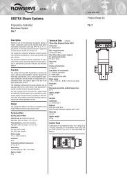
<strong>DM</strong> <strong>505</strong>, <strong>505</strong>Z<br />
Sheet no. <strong>DM</strong> <strong>505</strong>/2.1.061.1 - issue 12.06.2006<br />
Technical Data<br />
Connection G 1/2<br />
DN 15 - 25<br />
Nominal Pressure<br />
Inlet Pressure<br />
Outlet Pressure<br />
K vs -Value<br />
Sense Line<br />
Tightness acc. to VDI/VDE-guideline 2174<br />
(leakage rate K 0.05% of K vs -value)<br />
Description<br />
Medium-controlled pressure reducers are simple control valves offering<br />
accurate control while being easy to install and maintain. They<br />
control the pressure downstream of the valve without requiring pneumatic<br />
or electrical control elements.<br />
The <strong>DM</strong> <strong>505</strong> pressure reducing valve is a diaphragm-controlled springloaded<br />
proportional control valve for small volumes.<br />
This pressure reducer is manufactured from deep-drawn stainless<br />
steel featuring excellent corrosion resistance. The tubular inlet spigot<br />
of the valve body accommodates the seat aperture. The soft-sealing<br />
valve cone is guided in the seat assembly and connected with the control<br />
diaphragm by means of a stirrup which surrounds the seat assembly.<br />
The valve type <strong>505</strong> Z, recommended for temperatures up to 200 °C, is<br />
identical in its design apart from the metallic cone seal and water-cooled<br />
thermal protection between body and diaphragm.<br />
The spring module comprising bonnet, spring, adjusting screw, diaphragm<br />
and internal components, is connected to the valve body only<br />
by means of a clamp ring and two bolts. Changing the diaphragm or<br />
the complete spring assembly for a different control pressure range is<br />
extremely simple and does not call for special tools. The same applies<br />
to servicing and maintenance. Changing the control pressure setting<br />
does not affect the height of the valve (non increasing adjusting<br />
screw).<br />
The outlet pressure to be controlled is balanced across the diaphragm<br />
by the force of the valve spring (set pressure). As the outlet pressure<br />
rises above the pressure set using the adjusting screw, the valve cone<br />
moves towards the seat and the volume of medium is reduced. As the<br />
outlet pressure drops the valve control orifice increases; when the<br />
pipeline is depressurised the valve is open. Rotating the adjusjting<br />
screw clockwise increases the outlet pressure.<br />
<strong>DM</strong> <strong>505</strong> Z requires a pilot line (to be installed on-site); for outlet pressures<br />
K 1.1 bar <strong>DM</strong> <strong>505</strong> also requires a pilot line.<br />
STANDARD EQUIPMENT<br />
• All stainless steel construction<br />
• Non increasing adjusting screw<br />
• Quick-release body clamp ring<br />
• Pilot line connection<br />
(in the case of <strong>DM</strong> <strong>505</strong> only for outlet pressures K 1.1 bar)<br />
OPTIONS<br />
• Pressure gauge connection<br />
• For toxic or hazardous media: sealed bonnet complete with<br />
leakage line connection (incl. sealed adjusting screw). Must be<br />
installed with a leakage line capable of draining leaking medium<br />
safely and without pressure<br />
• Various diaphragm and seal materials suitable for your medium<br />
• Special versions on request<br />
Operating instructions, Know How and Safety instructions must be observed.<br />
The pressure has always been indicated as overpressure.<br />
We reserve the right to alter technical specifications without notice.<br />
WIR REGELN DAS SCHON<br />
FIRMLY IN CONTROL<br />
Inlet PN 250<br />
Outlet PN 1 - 25<br />
up to 250 bar<br />
<strong>DM</strong> <strong>505</strong>: 0.005 - 20 bar in 8 ranges<br />
<strong>DM</strong> <strong>505</strong>Z: 0.005 - 12 bar in 7 ranges<br />
0.15 - 0.9 m 3 /h<br />
<strong>DM</strong> <strong>505</strong>: setting range 0.005 - 1.1 bar<br />
<strong>DM</strong> <strong>505</strong>Z: all setting ranges<br />
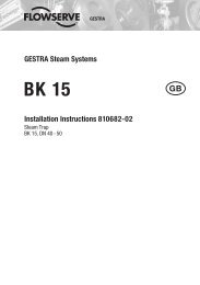
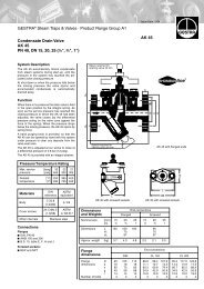
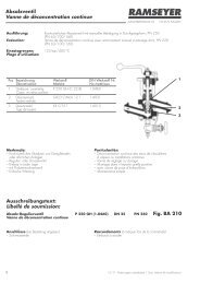
spring module<br />
adjusting screw<br />
(non increasing)<br />
body with valve<br />
Kvs-values [m 3 /h]<br />
for all body sizes, please select 0.15 0.4 0.9<br />
<strong>DM</strong> <strong>505</strong> setting ranges [bar]<br />
0.005-0.025 0.02-0.12 0.1-0.5 0.2-1.1 0.8-2.5 1-5 4-12 10-20<br />
<strong>DM</strong> <strong>505</strong>Z setting ranges [bar]<br />
0.005-0.025 0.02-0.12 0.1-0.5 0.2-1.1 0.8-2.5 1-5 4-12<br />
Permissible Reduction Ratio (max. p1/p2)<br />
max. p 1 = 250 bar<br />
setting ranges 0.005 - 0.025 and 0.02- 0.12 bar<br />
Kvs-value<br />
0.15<br />
ratio p1/p2<br />
1485<br />
setting range 0.1 - 0.5 bar<br />
Kvs-value<br />
ratio p1/p2<br />
setting range 0.2 - 1.1 bar<br />
Kvs-value<br />
0.15<br />
ratio p1/p2<br />
185<br />
setting range 0.8 - 2.5 bar<br />
0.4<br />
1000<br />
0.15 0.4<br />
405 280<br />
0.4<br />
125<br />
Kvs-value<br />
0.15 0.4<br />
ratio p1/p2<br />
105 70<br />
setting range 1 - 5 bar, 4 - 12 bar, 10 - 20 bar<br />
Kvs-value<br />
ratio p1/p2<br />
0.15<br />
39<br />
0.4<br />
27<br />
0.9<br />
750<br />
0.9<br />
210<br />
0.9<br />
100<br />
0.9<br />
50<br />
0.9<br />
20<br />
Mankenberg GmbH • Spenglerstraße 99 • D-23556 Lübeck • Tel. +49-451-8 79 75 0 • Fax +49-451-8 79 75 99 • gm@mankenberg.de • www.mankenberg.de