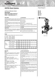
DM 505, 505Z
DM 505, 505Z
DM 505, 505Z

Erfolgreiche ePaper selbst erstellen
Machen Sie aus Ihren PDF Publikationen ein blätterbares Flipbook mit unserer einzigartigen Google optimierten e-Paper Software.
Regelventile für Druck<br />
<strong>DM</strong> <strong>505</strong> für Flüssigkeiten und Gase bis 130 °C, <strong>DM</strong> <strong>505</strong>Z für Dampf bis 200 °C<br />
für geringen Durchfluss<br />
<strong>DM</strong> <strong>505</strong>, <strong>505</strong>Z<br />
Blatt Nr. <strong>DM</strong> <strong>505</strong>/2.0.061.1 - Stand 12.06.2006<br />
Technische Daten<br />
Anschluss G 1/2<br />
DN 15 - 25<br />
Nenndruck<br />
Vordruck<br />
Hinterdruck<br />
K vs -Wert<br />
Steuerleitung<br />
Dichtheit nach VDI/VDE-Richtlinie 2174<br />
(Leckrate K 0,05 % des K vs -Wertes)<br />
Beschreibung<br />
Eigenmedium gesteuerte Druckminderer sind einfache Basisregler, die<br />
genaue Regelung bei leichter Installation und Wartung bieten. Sie regeln<br />
den Druck hinter dem Ventil ohne pneumatische oder elektrische<br />
Steuerteile.<br />
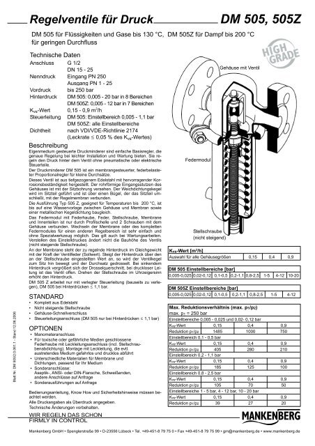
Der Druckminderer <strong>DM</strong> <strong>505</strong> ist ein membrangesteuerter, federbelasteter<br />
Proportionalregler für kleine Durchsätze.<br />
Dieses Ventil ist aus tiefgezogenem Edelstahl mit hervorragender Korrosionsbeständigkeit<br />
hergestellt. Der rohrförmige Eingangsstutzen des<br />
Gehäuses ist mit der Sitzbohrung versehen. Der Weichdichtungskegel<br />
wird im Sitzteil geführt und ist über einen Bügel, der das Sitzteil umschließt,<br />
mit der Regelmembran verbunden.<br />
Die Ausführung Typ <strong>505</strong> Z, geeignet für Temperaturen bis 200 °C, ist<br />
bis auf eine Wasservorlage zwischen Gehäuse und Membran sowie<br />
einer metallischen Kegeldichtung baugleich.<br />
Das Federmodul mit Federhaube, Feder, Stellschraube, Membrane<br />
und Innenteilen ist nur durch Profilschelle und 2 Schrauben mit dem<br />
Gehäuse verbunden. Wechseln der Membrane oder des kompletten<br />
Federmodules für einen anderen Regelbereich ist sehr einfach und<br />
ohne Spezialwerkzeug möglich. Das gilt auch bei Wartungsarbeiten.<br />
Verstellen des Einstelldruckes ändert nicht die Bauhöhe des Ventils<br />
(nicht steigende Stellschraube).<br />
An der Membrane steht der zu regelnde Hinterdruck im Gleichgewicht<br />
mit der Kraft der Ventilfeder (Sollwert). Steigt der Hinterdruck über den<br />
an der Stellschraube eingestellten Wert an, so wird der Ventilkegel<br />
zum Sitz hin bewegt und der Durchsatz gedrosselt. Bei sinkendem<br />
Hinterdruck vergrößert sich der Drosselquerschnitt, bei druckloser Leitung<br />
ist das Ventil offen. Drehen der Stellschraube im Uhrzeigersinn<br />
erhöht den Hinterdruck.<br />
<strong>DM</strong> <strong>505</strong> Z arbeitet nur mit verlegter Steuerleitung (bauseits zu verlegen),<br />
<strong>DM</strong> <strong>505</strong> bei Hinterdrücken K 1,1 bar.<br />
STANDARD<br />
• Komplett aus Edelstahl<br />
• Nicht steigende Stellschraube<br />
• Gehäuse-Schnellverschluss<br />
• Steuerleitungsanschluss (<strong>DM</strong> <strong>505</strong> nur bei Hinterdrücken K 1,1 bar)<br />
OPTIONEN<br />
• Manometeranschluss<br />
• Für toxische oder gefährliche Medien geschlossene<br />
Federhaube mit Leckleitungsanschluss (incl. Stellschraubenabdichtung).<br />
Montage mit Leckleitung, die evtl.<br />
austretendes Medium gefahrlos und drucklos abführt<br />
• Unterschiedliche Materialien für Membrane und<br />
Dichtungen, passend für Ihr Medium<br />
• Sonderanschlüsse:<br />
Aseptik-, ANSI- oder DIN-Flansche, Schweißenden,<br />
andere Anschlüsse auf Anfrage<br />
• Sonderausführungen auf Anfrage<br />
Bedienungsanleitung, Know How und Sicherheitshinweise müssen beachtet<br />
werden.<br />
Alle Druckangaben als Überdruck angegeben.<br />
Technische Änderungen vorbehalten.<br />
WIR REGELN DAS SCHON<br />
FIRMLY IN CONTROL<br />
Eingang PN 250<br />
Ausgang PN 1 - 25<br />
bis 250 bar<br />
<strong>DM</strong> <strong>505</strong>: 0,005 - 20 bar in 8 Bereichen<br />
<strong>DM</strong> <strong>505</strong>Z: 0,005 - 12 bar in 7 Bereichen<br />
0,15 - 0,9 m 3 /h<br />
<strong>DM</strong> <strong>505</strong>: Einstellbereich 0,005 - 1,1 bar<br />
<strong>DM</strong> <strong>505</strong>Z: alle Einstellbereiche<br />
Federmodul<br />
Stellschraube<br />
(nicht steigend)<br />
Gehäuse mit Ventil<br />
Kvs-Wert [m 3 /h]<br />
Auswahl für alle Gehäusegrößen 0,15 0,4 0,9<br />
<strong>DM</strong> <strong>505</strong> Einstellbereiche [bar]<br />
0,005-0,025 0,02-0,12 0,1-0,5 0,2-1,1 0,8-2,5 1-5 4-12 10-20<br />
<strong>DM</strong> <strong>505</strong>Z Einstellbereiche [bar]<br />
0,005-0,025 0,02-0,12 0,1-0,5 0,2-1,1 0,8-2,5 1-5 4-12<br />
Max. Reduktionsverhältnis (max. p1/p2)<br />
max. p 1 = 250 bar<br />
Einstellbereiche 0,005 - 0,025 und 0,02- 0,12 bar<br />
Kvs-Wert<br />
0,15<br />
Reduktion p1/p2 1485<br />
Einstellbereich 0,1 - 0,5 bar<br />
Kvs-Wert<br />
Reduktion p1/p2<br />
Einstellbereich 0,2 - 1,1 bar<br />
Kvs-Wert<br />
0,15<br />
Reduktion p1/p2 185<br />
Einstellbereich 0,8 - 2,5 bar<br />
0,4<br />
1000<br />
0,15 0,4<br />
405 280<br />
0,4<br />
125<br />
Kvs-Wert<br />
0,15 0,4<br />
Reduktion p1/p2 105 70<br />
Einstellbereiche 1 - 5 bar, 4 - 12 bar, 10 - 20 bar<br />
Kvs-Wert<br />
Reduktion p1/p2<br />
0,15<br />
39<br />
0,4<br />
27<br />
0,9<br />
750<br />
0,9<br />
210<br />
0,9<br />
100<br />
0,9<br />
50<br />
0,9<br />
20<br />
Mankenberg GmbH • Spenglerstraße 99 • D-23556 Lübeck • Tel. +49-451-8 79 75 0 • Fax +49-451-8 79 75 99 • gm@mankenberg.de • www.mankenberg.de
Regelventile für Druck<br />
<strong>DM</strong> <strong>505</strong> für Flüssigkeiten und Gase bis 130 °C, <strong>DM</strong> <strong>505</strong>Z für Dampf bis 200 °C<br />
für geringen Durchfluss<br />
<strong>DM</strong> <strong>505</strong>, <strong>505</strong>Z<br />
Werkstoffe<br />
Typ<br />
Temperatur<br />
Gehäuse<br />
Federhaube<br />
Innenteile<br />
Stellschraube<br />
Feder<br />
Ventildichtung EU<br />
Membrane<br />
Schutzfolie<br />
<strong>DM</strong> <strong>505</strong><br />
80 °C 130 °C<br />
CrNiMo-Stahl<br />
CrNi-Stahl<br />
CR<br />
PTFE (Option)<br />
CrNiMo-Stahl<br />
CrNi-Stahl<br />
FPM optional<br />
EP<strong>DM</strong> oder PTFE<br />
FPM oder EP<strong>DM</strong><br />
PTFE (Option)<br />
<strong>DM</strong> <strong>505</strong>Z<br />
200 °C<br />
CrNiMo-Stahl<br />
CrNi-Stahl<br />
CrNiMo-Stahl<br />
EP<strong>DM</strong><br />
PTFE (Option)<br />
<strong>DM</strong> <strong>505</strong><br />
Manometeranschluss<br />
G 1/4 (Option)<br />
A<br />
A 1<br />
B<br />
Abmessungen [mm]<br />
Einstellbereiche<br />
[bar]<br />
Alle Bereiche<br />
0,005<br />
0,02<br />
-<br />
-<br />
0,025<br />
0,12<br />
0,1 - 0,5<br />
0,2<br />
0,8<br />
1<br />
4<br />
10<br />
- 1,1<br />
- 2,5<br />
-<br />
5<br />
12<br />
20<br />
Maß<br />
A/A 1<br />
B<br />
C<br />
C<br />
D<br />
C<br />
C<br />
D<br />
C<br />
C<br />
D<br />
A/A 1<br />
A/A 1<br />
C<br />
C<br />
D<br />
C<br />
C<br />
D<br />
<strong>DM</strong><br />
<strong>505</strong> + <strong>505</strong>Z<br />
<strong>505</strong> + <strong>505</strong>Z<br />
<strong>505</strong><br />
<strong>505</strong>Z<br />
<strong>505</strong> + <strong>505</strong>Z<br />
<strong>505</strong><br />
<strong>505</strong>Z<br />
<strong>505</strong> + <strong>505</strong>Z<br />
<strong>505</strong><br />
<strong>505</strong>Z<br />
<strong>505</strong> + <strong>505</strong>Z<br />
<strong>505</strong><br />
<strong>505</strong>Z<br />
<strong>505</strong><br />
<strong>505</strong>Z<br />
<strong>505</strong> + <strong>505</strong>Z<br />
<strong>505</strong><br />
<strong>505</strong>Z<br />
<strong>505</strong> + <strong>505</strong>Z<br />
Flansche nach DIN 2635<br />
G 1/2 DN 15 DN 20 DN 25<br />
100 130 150 160<br />
53 53 53 53<br />
257 257 257 267<br />
387 387 387 297<br />
360 360 360 360<br />
257 257 257 267<br />
387 387 387 297<br />
264 264 264 264<br />
257 257 257 257<br />
387 387 387 387<br />
200 200 200 200<br />
100 180 180 180<br />
100 130 150 160<br />
196 196 196 196<br />
325 325 325 325<br />
138 138 138 138<br />
190 190 190 190<br />
325 325 325 325<br />
114 114 114 114<br />
Leckleitungsanschluss<br />
G 1/8<br />
(Option)<br />
Stellschraubenabdichtung<br />
(Option)<br />
<strong>DM</strong> <strong>505</strong>Z<br />
Abmessungen siehe <strong>DM</strong> <strong>505</strong><br />
Manometeranschluss<br />
G 1/4 (Option)<br />
Steuerleitungsanschluss<br />
G 1/4<br />
D<br />
C<br />
Gewichte [kg]<br />
Einstellbereiche<br />
[bar]<br />
0,005<br />
0,002<br />
-<br />
-<br />
0,025<br />
0,12<br />
0,1<br />
0,2<br />
0,8<br />
1<br />
4<br />
10<br />
- 0,5<br />
- 1,1<br />
- 2,5<br />
-<br />
5<br />
12<br />
20<br />
<strong>DM</strong><br />
<strong>505</strong><br />
<strong>505</strong>Z<br />
<strong>505</strong><br />
<strong>505</strong>Z<br />
<strong>505</strong><br />
<strong>505</strong>Z<br />
<strong>505</strong><br />
<strong>505</strong>Z<br />
<strong>505</strong><br />
<strong>505</strong>Z<br />
G 1/2<br />
6<br />
6,5<br />
5,5<br />
6<br />
4,5<br />
5<br />
2<br />
2,5<br />
1,5<br />
Sonderausführungen auf Anfrage.<br />
Alle Druckangaben als Überdruck angegeben.<br />
Technische Änderungen vorbehalten.<br />
2<br />
Flansche nach DIN 2635<br />
DN 15 DN 20 DN 25<br />
7,5 7,5 8<br />
8 8 8,5<br />
7 7 7,5<br />
7,5 7,5 8<br />
6 6 6,5<br />
6,5 6,5 7<br />
3,5 3,5 4<br />
4 4 4,5<br />
3<br />
3,5<br />
3<br />
3,5<br />
3,5<br />
4<br />
Einbauschema<br />
1 Schmutzfänger<br />
2 Absperrventile<br />
3 Druckminderer<br />
4 Sicherheitsventile<br />
Bypass für Wartung<br />
5 Manometer<br />
6 Steuerleitung G 1/4 (<strong>DM</strong> <strong>505</strong>Z)<br />
7 Leckleitung G 1/8 (Option)<br />
Steurleitungsanschluss 10 - 20 x DN hinter dem Ventil<br />
Blatt Nr. <strong>DM</strong> <strong>505</strong>/3.0.061.1 - Stand 12.06.2006<br />
WIR REGELN DAS SCHON<br />
FIRMLY IN CONTROL<br />
Mankenberg GmbH • Spenglerstraße 99 • D-23556 Lübeck • Tel. +49-451-8 79 75 0 • Fax +49-451-8 79 75 99 • gm@mankenberg.de • www.mankenberg.de
B E T R I E B S A N L E I T U N G<br />
DRUCKMINDERVENTIL<br />
TYP <strong>505</strong><br />
Blatt Nr.<br />
<strong>DM</strong> <strong>505</strong>/5.0.032.1.1<br />
WIRKUNGSWEISE<br />
Der zu regelnde Hinterdruck erzeugt an der Membrane eine Kraft, die im normalen Betriebszustand mit der Federkraft im<br />
Gleichgewicht steht. Bei Anstieg des Hinterdruckes über den mit der Stellschraube eingestellten Sollwert schließt das Ventil,<br />
bei Absinken unter den Sollwert öffnet es. Bei druckloser Leitung ist das Ventil offen.<br />
EINBAU<br />
Vor Einbau des Ventils ist die Rohrleitung sorgfältig durchzuspülen. Falls Fremdkörper und Schmutzpartikel während des Betriebes<br />
nicht vermeidbar sind, muss ein Schmutzfänger vorgesehen werden. Verpackungsmaterial einschließlich Plastikstopfen<br />
entfernen und Ventil spannungsfrei so in die Leitung einbauen, daß der Pfeil am Gehäuse in Durchflussrichtung zeigt.<br />
Die Federhaube kann - sofern nicht ausdrücklich anders angegeben - unten oder oben liegen. Typ <strong>505</strong> Z ist immer mit unten<br />
liegender Federhaube einzubauen, Typ <strong>505</strong> nur bei Flüssigkeiten mit Hinterdruck K 1,1 bar. Der Einbauort sollte sich in<br />
einem strömungstechnisch ungestörten horizontalen Leitungsabschnitt befinden. Krümmer, Absperrventile oder sonstige<br />
Drosselstellen dicht vor oder hinter dem Ventil sind zu vermeiden. Die Steuerleitungen* sind in einem Abstand von mindestens<br />
10 x Nennweite hinter dem Druckminderer anzuschließen. Der Durchmesser soll dem Anschluß am Ventil entsprechen.<br />
Bei Dampf K 0,1 bar ist die Steuerleitung mit einem Ausgleichsgefäß zu versehen.<br />
*nur bei Einstellbereichen -1,1 bar und bei Typ <strong>505</strong>Z<br />
SICHERHEITSEINRICHTUNGEN<br />
Druckminderer sind keine Absperrorgane, die einen dichten Ventilabschluss gewährleisten. Nach VDI/VDE-Richtlinie 2174 ist<br />
eine Leckrate von 0,05 % des Kvs-Wertes zulässig. Daher muss nach der Unfallverhütungsvorschrift VBG 17 eine Sicherheitseinrichtung<br />
vorgesehen werden, die ein Überschreiten des im System zulässigen Druckes verhindert. Der Druckminderer<br />
selbst ist - sofern nicht anders angegeben - so abzusichern, dass das 1,5-fache des maximalen Einstelldruckes nicht<br />
überschritten wird - z.B. bei Einstellbereich bis 5 bar: Der Abblasedruck des Sicherheitsventils darf maximal 7,5 bar betragen.<br />
Er darf jedoch nicht höher als der Nenndruck des Gehäuses sein.<br />
Ferner ist sicherzustellen, dass das Fluid, das bei Membranbruch aus der Federhaube austritt, zu keiner Gefährdung führt.<br />
Gegebenenfalls muss an der Atmungsbohrung der Federhaube eine Abführleitung angeschlossen werden.<br />
INBETRIEBNAHME<br />
Funktion und Dichtheit des Druckminderers wurden im Werk geprüft. Er wird mit entspannter Feder geliefert. Bei Dampf ist<br />
der Steuerraum vor Inbetriebnahme über den Steueranschluss mit Wasser zu füllen. Bei Inbetriebnahme ist die eingangsseitige<br />
Armatur langsam zu öffnen, wobei gewährleistet sein muss, dass das Fluid ausgangsseitig abgeführt wird. Druckstöße<br />
müssen vermieden werden. Anschließend ist der zu regelnde Hinterdruck mit der Stellschraube einzustellen. Die Feder nicht<br />
über den angegebenen max. Einstelldruck anspannen, so dass der Hub eingeschränkt bzw. das Ventil in Offenstellung<br />
blockiert wird. Durch leichten axialen Druck auf die Stellschraube kann der Hinterdruck kurzzeitig erhöht werden.<br />
WARTUNG<br />
Abhängig von den Eigenschaften des Mediums und den Betriebsumständen in der Anlage ist eine Wartung jährlich oder<br />
auch in kürzeren Abständen durchzuführen bzw. die Funktion des Ventils zu überprüfen.<br />
Bei Wartungen oder Störungen ist wie folgt vorzugehen: Ventil drucklos machen, Feder entspannen, Federhaube abnehmen,<br />
Steuerteile auf Gängigkeit prüfen. Klemmstellen mit feinem Schmirgelleinen abziehen. Undichtheit oder Schäden an der<br />
Membrane werden durch aus der Federhaubenöffnung austretendes Fluid angezeigt. Ist die Undichtheit durch leichtes<br />
Nachziehen der Schrauben an der Schelle bzw. an der Federhaube nicht zu beheben, Membrane überprüfen. Hierzu Feder<br />
entspannen. Federhaube demontieren. Spindelmutter fest anziehen. Alle Teile wieder montieren und auf Dichtheit prüfen. Ist<br />
die Undichtheit noch nicht behoben, muß die Membrane erneuert werden. Hierzu Spindelmutter an Membrane lösen, Membranscheibe<br />
abziehen und Membrane mit O-Ring (soweit vorhanden) herausnehmen. Nach dem Einlegen der neuen Membrane<br />
mit O-Ring müssen die Spindelmutter und die Schrauben an der Schelle fest angezogen werden, aber Schrauben an<br />
der Federhaube nur leicht, da sonst die Membrane zerquetscht wird.<br />
Stark ansteigender Hinterdruck bei geringer Entnahme weist auf eine defekte Kegeldichtung hin. Beim Ausbau des Ventilkegels<br />
Federhaube wie vor beschrieben abnehmen, Membrane von der Spindel demontieren und die Spindel ca. 10 mm aus<br />
dem Bügel herausschrauben. Anschließend Spindel mit Bügel und Kegel anheben (gegen Gehäuseboden), Richtung Ausgang<br />
seitlich am Sitzstück vorbeiführen und herausziehen. Ventilkegel auswechseln. Beim Einschrauben der Spindel in den<br />
Bügel ist auf Freigängigkeit des Kegels im Sitzstück zu achten.<br />
WICHTIG: O-Ringe, Gleitflächen und Gewinde fetten. EP<strong>DM</strong>-O-Ringe mit Parker "Super-Lube" einsetzen (Achtung:<br />
silikonhaltig). Interne Schmierstoffe beachten.<br />
ERSATZTEILE<br />
Bei Bestellung von Ersatzteilen Fabrik-Nummer bzw. Artikel-Nummer des Reglers und Bezeichnung sowie Pos.- Nummern<br />
der Teile angeben.<br />
1 Schmutzfänger*<br />
2 Absperrventile<br />
3 Druckminderer*<br />
4 Sicherheitsventil*<br />
5 Manometer*<br />
6 Steuerleitung G 1/4<br />
7 Ausgleichsgefäß*<br />
* verwenden Sie<br />
MANKENBERG-Produkte<br />
Technische Änderungen vorbehalten.<br />
03.04.2003<br />
Mankenberg GmbH • D-23556 Lübeck • Spenglerstr. 99 • Tel. +49 - 451 - 8 79 75 0 • Fax. +49 - 451 - 8 79 75 99 • www.mankenberg.de • e-mail: gm@mankenberg.de
Pressure Control Valves<br />
<strong>DM</strong> <strong>505</strong> for liquids and gases up to 130 °C, <strong>DM</strong> <strong>505</strong>Z for steam up to 200 °C<br />
for low flow rates<br />
<strong>DM</strong> <strong>505</strong>, <strong>505</strong>Z<br />
Sheet no. <strong>DM</strong> <strong>505</strong>/2.1.061.1 - issue 12.06.2006<br />
Technical Data<br />
Connection G 1/2<br />
DN 15 - 25<br />
Nominal Pressure<br />
Inlet Pressure<br />
Outlet Pressure<br />
K vs -Value<br />
Sense Line<br />
Tightness acc. to VDI/VDE-guideline 2174<br />
(leakage rate K 0.05% of K vs -value)<br />
Description<br />
Medium-controlled pressure reducers are simple control valves offering<br />
accurate control while being easy to install and maintain. They<br />
control the pressure downstream of the valve without requiring pneumatic<br />
or electrical control elements.<br />
The <strong>DM</strong> <strong>505</strong> pressure reducing valve is a diaphragm-controlled springloaded<br />
proportional control valve for small volumes.<br />
This pressure reducer is manufactured from deep-drawn stainless<br />
steel featuring excellent corrosion resistance. The tubular inlet spigot<br />
of the valve body accommodates the seat aperture. The soft-sealing<br />
valve cone is guided in the seat assembly and connected with the control<br />
diaphragm by means of a stirrup which surrounds the seat assembly.<br />
The valve type <strong>505</strong> Z, recommended for temperatures up to 200 °C, is<br />
identical in its design apart from the metallic cone seal and water-cooled<br />
thermal protection between body and diaphragm.<br />
The spring module comprising bonnet, spring, adjusting screw, diaphragm<br />
and internal components, is connected to the valve body only<br />
by means of a clamp ring and two bolts. Changing the diaphragm or<br />
the complete spring assembly for a different control pressure range is<br />
extremely simple and does not call for special tools. The same applies<br />
to servicing and maintenance. Changing the control pressure setting<br />
does not affect the height of the valve (non increasing adjusting<br />
screw).<br />
The outlet pressure to be controlled is balanced across the diaphragm<br />
by the force of the valve spring (set pressure). As the outlet pressure<br />
rises above the pressure set using the adjusting screw, the valve cone<br />
moves towards the seat and the volume of medium is reduced. As the<br />
outlet pressure drops the valve control orifice increases; when the<br />
pipeline is depressurised the valve is open. Rotating the adjusjting<br />
screw clockwise increases the outlet pressure.<br />
<strong>DM</strong> <strong>505</strong> Z requires a pilot line (to be installed on-site); for outlet pressures<br />
K 1.1 bar <strong>DM</strong> <strong>505</strong> also requires a pilot line.<br />
STANDARD EQUIPMENT<br />
• All stainless steel construction<br />
• Non increasing adjusting screw<br />
• Quick-release body clamp ring<br />
• Pilot line connection<br />
(in the case of <strong>DM</strong> <strong>505</strong> only for outlet pressures K 1.1 bar)<br />
OPTIONS<br />
• Pressure gauge connection<br />
• For toxic or hazardous media: sealed bonnet complete with<br />
leakage line connection (incl. sealed adjusting screw). Must be<br />
installed with a leakage line capable of draining leaking medium<br />
safely and without pressure<br />
• Various diaphragm and seal materials suitable for your medium<br />
• Special versions on request<br />
Operating instructions, Know How and Safety instructions must be observed.<br />
The pressure has always been indicated as overpressure.<br />
We reserve the right to alter technical specifications without notice.<br />
WIR REGELN DAS SCHON<br />
FIRMLY IN CONTROL<br />
Inlet PN 250<br />
Outlet PN 1 - 25<br />
up to 250 bar<br />
<strong>DM</strong> <strong>505</strong>: 0.005 - 20 bar in 8 ranges<br />
<strong>DM</strong> <strong>505</strong>Z: 0.005 - 12 bar in 7 ranges<br />
0.15 - 0.9 m 3 /h<br />
<strong>DM</strong> <strong>505</strong>: setting range 0.005 - 1.1 bar<br />
<strong>DM</strong> <strong>505</strong>Z: all setting ranges<br />
spring module<br />
adjusting screw<br />
(non increasing)<br />
body with valve<br />
Kvs-values [m 3 /h]<br />
for all body sizes, please select 0.15 0.4 0.9<br />
<strong>DM</strong> <strong>505</strong> setting ranges [bar]<br />
0.005-0.025 0.02-0.12 0.1-0.5 0.2-1.1 0.8-2.5 1-5 4-12 10-20<br />
<strong>DM</strong> <strong>505</strong>Z setting ranges [bar]<br />
0.005-0.025 0.02-0.12 0.1-0.5 0.2-1.1 0.8-2.5 1-5 4-12<br />
Permissible Reduction Ratio (max. p1/p2)<br />
max. p 1 = 250 bar<br />
setting ranges 0.005 - 0.025 and 0.02- 0.12 bar<br />
Kvs-value<br />
0.15<br />
ratio p1/p2<br />
1485<br />
setting range 0.1 - 0.5 bar<br />
Kvs-value<br />
ratio p1/p2<br />
setting range 0.2 - 1.1 bar<br />
Kvs-value<br />
0.15<br />
ratio p1/p2<br />
185<br />
setting range 0.8 - 2.5 bar<br />
0.4<br />
1000<br />
0.15 0.4<br />
405 280<br />
0.4<br />
125<br />
Kvs-value<br />
0.15 0.4<br />
ratio p1/p2<br />
105 70<br />
setting range 1 - 5 bar, 4 - 12 bar, 10 - 20 bar<br />
Kvs-value<br />
ratio p1/p2<br />
0.15<br />
39<br />
0.4<br />
27<br />
0.9<br />
750<br />
0.9<br />
210<br />
0.9<br />
100<br />
0.9<br />
50<br />
0.9<br />
20<br />
Mankenberg GmbH • Spenglerstraße 99 • D-23556 Lübeck • Tel. +49-451-8 79 75 0 • Fax +49-451-8 79 75 99 • gm@mankenberg.de • www.mankenberg.de
Pressure Control Valves<br />
<strong>DM</strong> <strong>505</strong>, <strong>505</strong>Z<br />
<strong>DM</strong> <strong>505</strong> for liquids and gases up to 130 °C, <strong>DM</strong> <strong>505</strong>Z for steam up to 200 °C<br />
for low flow rates<br />
Materials<br />
Type<br />
<strong>DM</strong> <strong>505</strong><br />
<strong>DM</strong> <strong>505</strong>Z<br />
Temperature<br />
Body<br />
Spring Cap<br />
Internals<br />
Set Screw<br />
Spring<br />
Valve Seal<br />
80 °C 130 °C<br />
CrNiMo-steel<br />
CrNi-steel<br />
EU<br />
CrNiMo-steel<br />
CrNi-steel<br />
FPM optional<br />
EP<strong>DM</strong> or PTFE<br />
200 °C<br />
CrNiMo-steel<br />
CrNi-steel<br />
CrNiMo-steel<br />
<strong>DM</strong> <strong>505</strong><br />
manometer<br />
connection<br />
G 1/4 (option)<br />
A<br />
A 1<br />
B<br />
Diaphragm<br />
Protection Foil<br />
CR<br />
PTFE (option)<br />
FPM oder EP<strong>DM</strong><br />
PTFE (option)<br />
EP<strong>DM</strong><br />
PTFE (option)<br />
Dimensions [mm]<br />
pressure range<br />
[bar]<br />
size<br />
<strong>DM</strong><br />
G 1/2<br />
flanges acc. to DIN 2635<br />
DN 15 DN 20 DN 25<br />
D<br />
0.005<br />
0.02<br />
all ranges<br />
-<br />
-<br />
0.025<br />
0.12<br />
A/A 1<br />
B<br />
C<br />
C<br />
D<br />
C<br />
<strong>505</strong> + <strong>505</strong>Z<br />
<strong>505</strong> + <strong>505</strong>Z<br />
<strong>505</strong><br />
<strong>505</strong>Z<br />
<strong>505</strong> + <strong>505</strong>Z<br />
<strong>505</strong><br />
100<br />
53<br />
257<br />
387<br />
360<br />
257<br />
130<br />
53<br />
257<br />
387<br />
360<br />
257<br />
150<br />
53<br />
257<br />
387<br />
360<br />
257<br />
160<br />
53<br />
267<br />
297<br />
360<br />
267<br />
leakage line connection<br />
G 1/8 (option)<br />
adjusting screw sealing<br />
(option)<br />
C<br />
0.1 - 0.5<br />
C<br />
D<br />
<strong>505</strong>Z<br />
<strong>505</strong> + <strong>505</strong>Z<br />
387<br />
264<br />
387<br />
264<br />
387<br />
264<br />
297<br />
264<br />
0.2<br />
0.8<br />
1<br />
4<br />
10<br />
- 1.1<br />
- 2.5<br />
-<br />
5<br />
12<br />
20<br />
C<br />
C<br />
D<br />
C<br />
C<br />
D<br />
C<br />
C<br />
<strong>505</strong><br />
<strong>505</strong>Z<br />
<strong>505</strong> + <strong>505</strong>Z<br />
<strong>505</strong><br />
<strong>505</strong>Z<br />
<strong>505</strong> + <strong>505</strong>Z<br />
<strong>505</strong><br />
<strong>505</strong>Z<br />
257<br />
387<br />
200<br />
196<br />
326<br />
138<br />
190<br />
320<br />
257<br />
387<br />
200<br />
196<br />
326<br />
138<br />
190<br />
320<br />
D <strong>505</strong> + <strong>505</strong>Z 114 114<br />
257<br />
387<br />
200<br />
196<br />
326<br />
138<br />
190<br />
320<br />
257<br />
387<br />
200<br />
196<br />
326<br />
138<br />
190<br />
320<br />
114 114<br />
<strong>DM</strong> <strong>505</strong>Z<br />
dimensions see <strong>DM</strong> <strong>505</strong><br />
manometer connection<br />
G 1/4 (option)<br />
Weights [kg]<br />
pressure range<br />
[bar]<br />
0.005<br />
0.002<br />
0.1<br />
0.2<br />
0.8<br />
1<br />
4<br />
10<br />
-<br />
-<br />
0.025<br />
0.12<br />
- 0.5<br />
- 1.1<br />
- 2.5<br />
-<br />
5<br />
12<br />
20<br />
<strong>DM</strong><br />
<strong>505</strong><br />
<strong>505</strong>Z<br />
<strong>505</strong><br />
<strong>505</strong>Z<br />
<strong>505</strong><br />
<strong>505</strong>Z<br />
<strong>505</strong><br />
<strong>505</strong>Z<br />
<strong>505</strong><br />
<strong>505</strong>Z<br />
G 1/2<br />
6<br />
6.5<br />
5.5<br />
6<br />
4.5<br />
5<br />
2<br />
2.5<br />
1.5<br />
2<br />
flanges acc. to DIN 2635<br />
DN 15 DN 20 DN 25<br />
7.5<br />
8<br />
7<br />
7.5<br />
6<br />
6.5<br />
3.5<br />
4<br />
3<br />
3.5<br />
7.5<br />
8<br />
7<br />
7.5<br />
6<br />
6.5<br />
3.5<br />
4<br />
3<br />
3.5<br />
8<br />
8.5<br />
7.5<br />
8<br />
6.5<br />
7<br />
4<br />
4.5<br />
3.5<br />
Special designs on request.<br />
The pressure has always been indicated as overpressure.<br />
Mankenberg reserves the right, to alter or improve the designs or specifications<br />
of the products described herein without notice.<br />
4<br />
sense line connection<br />
G 1/4<br />
Recommended Installation<br />
1 Strainer<br />
2 Shutoff Valves<br />
3 Pressure Reducer<br />
4 Safety Valve<br />
Bypass for maintenance<br />
5 Pressure Gauge<br />
6 Sense Line G 1/4 (<strong>DM</strong> <strong>505</strong>Z)<br />
7 Leakage Line G 1/8 (option)<br />
Sense line connection 10 - 20 x DN behind the valve<br />
Sheet no. <strong>DM</strong> <strong>505</strong>/3.1.061.1 - issue 12.06.2006<br />
WIR REGELN DAS SCHON<br />
FIRMLY IN CONTROL<br />
Mankenberg GmbH • Spenglerstraße 99 • D-23556 Lübeck • Tel. +49-451-8 79 75 0 • Fax +49-451-8 79 75 99 • gm@mankenberg.de • www.mankenberg.de
OPERATING INSTRUCTIONS<br />
PRESSURE REDUCING VALVE<br />
Sheet no.<br />
TYPE <strong>505</strong> <strong>DM</strong> <strong>505</strong>/5.1.032.1.1<br />
OPERATION<br />
The outlet pressure to be controlled exerts a force on the diaphragm which balances the load exerted by the spring in the normal operating<br />
state. As the outlet pressure increases above the pressure set via the setting screw, the valve closes; the valve opens when the outlet<br />
pressure falls below the set pressure. The valve is open when the pipeline is depressurised.<br />
INSTALLATION<br />
Before installing the valve the pipeline should be flushed through thoroughly. If coarse particles of dirt and foreign bodies cannot be avoided<br />
during operation, a strainer should be fitted. Remove any packaging material including<br />
plastic plugs and install the valve into the pipeline ensuring that the arrow on the valve points in the direction of flow and the valve is free<br />
of stress. The spring cover can, unless specified otherwise, be at the top or the bottom.<br />
Type <strong>505</strong>Z should always be installed with the spring cover at the bottom; type <strong>505</strong> should be installed with its spring cover at the bottom<br />
only for liquids and outlet pressures up to 1.1 bar. The installation site should always be in a horizontal section of the pipeline that is not<br />
subject to turbulence. Manifolds, stop valves or other restrictions immediately upstream or downstream from the valve should be avoided.<br />
Pilot lines* should be connected at a distance of at least 10 times nominal bore downstream from the pressure reducer. The diameter<br />
should match the valve connection diameter. In the case of steam installations operating at pressures below 0.1 bar the pilot line should<br />
be fitted with an expansion vessel.<br />
*applies only to pressure settings up to 1.1 bar and valve type <strong>505</strong>Z<br />
SAFETY DEVICES<br />
Pressure reducers are not stop valves which provide a leak-proof shutoff function. According to VDI/VDE Guideline 2174 a leakage rate of<br />
0.05% of the constant volume flow value is permitted. For this reason the German accident<br />
prevention regulations VBG17 specify the installation of a safety device which prevents the maximum permitted system pressure being<br />
exceeded. Unless otherwise specified, the pressure reducer itself should be protected in such a way that 1.5 times the maximum set pressure<br />
is not exceeded; e.g. with a set pressure of 5 bar the relief pressure of the safety valve should not exceed 7.5 bar. The relief pressure<br />
must, however, not exceed the rated pressure of the valve body.<br />
In addition the user must ensure that in the case of a diaphragm rupture any escaping fluid does not create a hazard. If necessary, a drain<br />
line should be connected to the diaphragm housing breather orifice.<br />
COMMISSIONING<br />
The pressure reducer has been tested for correct operation and leakage before despatch from the works. The valve is supplied with the<br />
spring relaxed. In the case of steam applications the control chamber should be filled with water via the pilot line connection before the<br />
valve is commissioned. During commissioning the valve inlet should be opened slowly ensuring that the fluid drains from the outlet side.<br />
Pressure surges must be avoided. Finally the outlet pressure should be set using the setting screw. The spring should not be compressed<br />
beyond the specified maximum pressure to avoid restricting the diaphragm movement or jamming the valve in open position. The outlet<br />
pressure may be increased temporarily by applying a light axial pressure to the setting screw.<br />
MAINTENANCE<br />
Depending on the properties of the medium and the operating conditions of the system, the valve should be serviced and checked for correct<br />
functioning once a year or at shorter intervals.<br />
The following procedure should be adopted in case of maintenance or repair: depressurise valve, relax spring, remove spring cover.<br />
Check control mechanism for freedom of movement. In case of jamming remove any high spots using fine emery cloth. Leakage or diaphragm<br />
damage is indicated by fluid escaping from the spring cover breather orifice. If a leak cannot be remedied by slightly tightening the<br />
clamp ring or spring cover bolts, the diaphragm should be checked. To do this the spring should be relaxed, the spring cover removed and<br />
the spindle nut tightened. Then all components should be reassembled and the valve checked for leaks. If the leak persists the diaphragm<br />
should be renewed as follows: unscrew spindle nut on diaphragm, withdraw diaphragm disc and remove diaphragm together with its O-<br />
ring (if fitted). Once the new diaphragm has been fitted complete with O-ring, the spindle nut and clamp ring bolts should be fully tightened<br />
whereas the spring cover screws should be torqued only gently to avoid crushing the diaphragm.<br />
A strongly increasing outlet pressure at low flow rates indicates a defective cone seal. To remove the valve cone remove the spring cover<br />
as described above, remove the diaphragm from the spindle and unscrew the spindle approximately 10 mm from its guide. Then lift the<br />
spindle complete with its guide and cone (towards the bottom of the valve body) and withdraw completely past the seat towards the outlet..<br />
Renew the valve cone. When screwing the spindle back into its guide please make sure that the valve cone moves freely in its seat.<br />
IMPORTANT: Lubricate O-rings, sliding surfaces and threads with grease.<br />
Use Parker "Super-Lube" to lubricate EP<strong>DM</strong> O-rings (Please note: this lubricant contains silicone). Use only recommended lubricants<br />
for internal lubrication.<br />
REPLACEMENT PARTS<br />
When ordering spare parts please provide the serial or catalogue number of the<br />
product as well as the item number on the drawing and an accurate description of the part.<br />
1 Strainer*<br />
2 Shut-off valve<br />
3 Pressure Reducer*<br />
4 Safety valve*<br />
5 Pressure gauge*<br />
6 Control line G 1/4<br />
7 Damping pot<br />
* use MANKENBERG -<br />
products<br />
Mankenberg reserves the right, without notice, to alter or improve the designs or specifications of the products described herein.<br />
31.03.2003<br />
Mankenberg GmbH • Spenglerstr. 99 • D-23556 Lübeck • Tel. +49 - 451 - 8 79 75 0 • Fax. +49 - 451 - 8 79 75 99 • www.mankenberg.de • e-mail: gm@mankenberg.de