Installation Instructions 810682-02 GESTRA Steam Systems - André ...
Installation Instructions 810682-02 GESTRA Steam Systems - André ...
Installation Instructions 810682-02 GESTRA Steam Systems - André ...

You also want an ePaper? Increase the reach of your titles
YUMPU automatically turns print PDFs into web optimized ePapers that Google loves.
<strong>GESTRA</strong> <strong>Steam</strong> <strong>Systems</strong><br />
BK 15<br />
<br />
<strong>Installation</strong> <strong>Instructions</strong> <strong>810682</strong>-<strong>02</strong><br />
<strong>Steam</strong> Trap<br />
BK 15, DN 40 - 50
Contents<br />
Important Notes<br />
Page<br />
Usage for the intended purpose...............................................................................................................4<br />
Safety note..............................................................................................................................................4<br />
Danger....................................................................................................................................................4<br />
Attention.................................................................................................................................................4<br />
PED (Pressure Equipment Directive)........................................................................................................4<br />
ATEX (Atmosphère Explosible).................................................................................................................4<br />
Explanatory Notes<br />
Scope of supply.......................................................................................................................................5<br />
Description..............................................................................................................................................5<br />
Function..................................................................................................................................................5<br />
Design.....................................................................................................................................................5<br />
Technical Data<br />
Pressure / temperature ratings................................................................................................................6<br />
Corrosion resistance................................................................................................................................6<br />
Sizing......................................................................................................................................................6<br />
Name plate / Marking..............................................................................................................................6<br />
Design<br />
Component parts BK 15 .........................................................................................................................7<br />
Key.........................................................................................................................................................8<br />
<strong>Installation</strong><br />
BK 15......................................................................................................................................................9<br />
Flanged design........................................................................................................................................9<br />
Socket-weld design.................................................................................................................................9<br />
Butt-weld design.....................................................................................................................................9<br />
Attention...............................................................................................................................................10<br />
Heat treatment of welds........................................................................................................................10<br />
Commissioning<br />
BK 15....................................................................................................................................................11<br />
Danger..................................................................................................................................................11<br />
Adjusting regulator (undercooling, controlled steam flowrate)................................................................11<br />
Restoring factory setting.......................................................................................................................11<br />
Tools.....................................................................................................................................................11
Contents – continued –<br />
Operation<br />
Page<br />
BK 15....................................................................................................................................................12<br />
Maintenance<br />
Checking steam trap ............................................................................................................................12<br />
Cleaning / replacing regulator and strainer ...........................................................................................12<br />
Tools ....................................................................................................................................................12<br />
Torques.................................................................................................................................................13<br />
Spare Parts<br />
Spare parts list .....................................................................................................................................13<br />
Annex<br />
Declaration of Conformity .....................................................................................................................14
Important Notes<br />
Usage for the intended purpose<br />
Use steam trap BK 15 only for the discharge of condensate in steam lines or for air venting.<br />
Use this equipment only within the specified pressure and temperature ratings and check corrosion<br />
resistance and chemical suitability for the application in question.<br />
Safety Note<br />
The equipment must only be installed and commissioned by qualified and competent staff.<br />
Retrofitting and maintenance work must only be performed by qualified staff who – through adequate<br />
training – have achieved a recognised level of competence.<br />
Danger<br />
The steam trap is under pressure during operation.<br />
When loosening flanged connections, sealing plugs or the regulator hot water or steam<br />
may escape.<br />
This presents the danger of severe scalds to the whole body.<br />
<strong>Installation</strong> and maintenance work should only be carried out when the system is<br />
depressurized: isolate the trap from both upstream and downstream pressure.<br />
The steam trap becomes hot during operation.<br />
This presents the risk of severe burns to hands and arms.<br />
<strong>Installation</strong> and maintenance work should only be carried out at room temperatures.<br />
Sharp edges on internals present a danger of cuts to hands.<br />
Always wear industrial gloves for installation and maintenance work.<br />
Attention<br />
The name plate indicates the technical specification of the equipment.<br />
Do not commission or operate a steam trap without a name plate.<br />
PED (Pressure Equipment Directive)<br />
The equipment fulfills the requirements of the Pressure Equipment Directive PED 97/23/EC.<br />
Applicable with fluids of group 2.<br />
According to section 3.3 the equipment is excluded from the scope of this directive and must therefore<br />
not be CE marked.<br />
ATEX (Atmosphère Explosible)<br />
The equipment does not have its own potential source of ignition and is therefore not subject to the<br />
ATEX Directive 94/9/EC.<br />
The equipment can be used in potentially explosive areas 0, 1, 2, 20, 21, 22 (1999/92/EC).<br />
The equipment is not Ex marked.
Explanatory Notes<br />
Scope of supply<br />
BK 15<br />
1 <strong>Steam</strong> trap type BK 15<br />
1 <strong>Installation</strong> manual<br />
Description<br />
Thermostatic/thermodynamic steam trap with corrosion-resistant regulator unaffected by waterhammer.<br />
The Duo stainless steel regulator is externally adjustable. With integral strainer and nonreturn<br />
valve action. Asbestos-free cover gasket (graphite). <strong>Installation</strong> in any position.<br />
The steam trap is adjusted at our factory to discharge condensate with virtually no banking-up.<br />
More undercooling (banking-up of condensate) can be manually adjusted during operation from the<br />
outside.<br />
Function<br />
During start-up of the plant the Duo stainless steel plates are flat. The service pressure acts in the<br />
opening direction, the valve is completely open. As the condensate temperature rises, the plates<br />
deflect, drawing the stage nozzle towards the closed position. As the condensate temperature sinks,<br />
the deflection of the Duo stainless steel plates decreases and the steam trap opens at the adjusted<br />
opening temperature.<br />
The thermostatic and spring characteristics of the stack of plates are balanced such that condensate is<br />
always discharged at a given undercooling temperature.<br />
The trap provides automatic air-venting at start-up and during operation. The correct functioning of the<br />
BK 15 is neither affected by upstream pressure variations nor by back pressure. The BK 15 can also be<br />
used for thermal air-venting in steam systems.<br />
Design<br />
BK 15<br />
Version for installation in horizontal and vertical lines.
Technical Data<br />
Pressure/temperature ratings<br />
BK 15<br />
For pressure/temperature ratings see specification on trap body or name plate:<br />
Pressure class PN/Class, material number, max. temperature, max. pressure, max. differential pressure.<br />
Corrosion resistance<br />
When used for its intended purpose the safe functioning of the steam trap will not be impaired by<br />
corrosion.<br />
Sizing<br />
The valve body must not be subjected to pulsating loads. The dimensional allowances for corrosion<br />
reflect the latest state of technology.<br />
Name plate / Marking<br />
The pressure / temperature ratings are indicated on the trap body / the name plate.<br />
For more information see <strong>GESTRA</strong> data sheets and Technical Information.<br />
According to EN 19 the name plate and the valve body indicate the type and design:<br />
■ Name / logo of the manufacturer<br />
■ Type designation<br />
■ Pressure class PN or Class<br />
■ Material number<br />
■ Max. temperature<br />
■ Max. pressure<br />
■ Flow direction<br />
3<br />
■ Stamp on trap body, e. g. specifies the quarter and the year of production<br />
05<br />
(Example: 3 rd quarter 2005).<br />
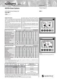
Nominal size<br />
Ratings acc. to<br />
EN ISO 26552<br />
Thermovit regulator<br />
Standard design<br />
U 30 K undercooling<br />
Fig. 1
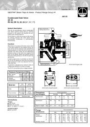
Design<br />
Component parts BK 15<br />
N<br />
A<br />
B<br />
C<br />
D<br />
E<br />
F<br />
G<br />
H<br />
I<br />
J<br />
K<br />
Fig. 2<br />
M<br />
L
Design – continued –<br />
Key<br />
A Union nut ¾" BSP<br />
B Gland ring<br />
C Packing 9 x 14 x 7<br />
D Cover<br />
E Adjusting screw<br />
F Guide ring<br />
G Thermovit regulator<br />
H Strainer<br />
I Bush (force-fit, no spare part)<br />
J Cover gasket 92.7 x 1<strong>02</strong> x 1<br />
K Body<br />
L Name plate<br />
M Hexagon nut M 12<br />
N Hexagon bolt M 12
<strong>Installation</strong><br />
BK 15<br />
The steam trap BK 15 can be installed in any position, taking the flow arrow into account. In the case<br />
of a horizontal installation, make sure that the cover is on top.<br />
Flanged design<br />
1. Take care of correct position of installation.<br />
2. Take care of flow direction. The flow arrow is on the trap body.<br />
3. Consider space required for opening trap. When the trap is installed a minimum space of 90 mm is<br />
required for removing cover D.<br />
4. Remove plastic plugs. They are only used as transit protection.<br />
5. Clean seating surfaces of both flanges.<br />
6. Install steam trap.<br />
Socket-weld design<br />
1. Take care of correct position of installation.<br />
2. Take care of flow direction. The flow arrow is on the trap body.<br />
3. Consider space required for opening trap. When the trap is installed a minimum space of 90 mm is<br />
required for removing the cover D.<br />
4. Remove plastic plugs. They are only used as transit protection.<br />
5. Remove regulator as described under Maintenance.<br />
6. Clean socket-weld ends.<br />
7. Arc-weld trap (welding process 111 and 141 in accordance with DIN EN 24063) in place.<br />
Butt-weld design<br />
1. Take care of correct position of installation.<br />
2. Take care of flow direction. The flow arrow is on the trap body.<br />
3. Consider space required for opening trap. When the trap is installed a minimum space of 90 mm is<br />
required for removing the cover D.<br />
4. Remove plastic plugs. They are only used as transit protection.<br />
5. Clean butt-weld ends.<br />
6. Arc-weld trap in place (welding process 111 and 141 in accordance with DIN EN 24063) or<br />
use gas-welding process (welding process 3 in accordance with DIN EN 24063).
<strong>Installation</strong> – continued –<br />
Attention<br />
Heat treatment of welds<br />
n Only qualified welders certified e. g. according to DIN EN 287 may weld the steam trap<br />
into pressurized lines.<br />
n Do not insulate the steam trap.<br />
A subsequent heat treatment of the welds is not required provided that the pipe is made from a<br />
material that is similar to that used for the trap body.<br />
If a particular pipe material makes a heat treatment necessary make sure the heat treatment is<br />
restricted to the close vicinity of the weld. Should this not be possible remove the Thermovit regulator<br />
before carrying out the heat treatment.<br />
10
Commissioning<br />
BK 15<br />
Make sure that all flange bolts are firmly fastened, ensuring tight shut-off.<br />
Danger<br />
The steam trap is under pressure at start-up and during operation.<br />
When loosening the union nut A hot water or steam may escape.<br />
This presents the danger of severe burns and scalds to the whole body.<br />
The steam trap becomes hot during operation.<br />
This presents the risk of severe burns to hands and arms.<br />
<strong>Installation</strong> and maintenance work should only be carried out at room temperatures.<br />
Always wear industrial gloves when adjusting the regulator.<br />
Adjusting regulator (undercooling, controlled steam flowrate)<br />
The regulator of the BK 15 is adjusted at our factory to close steam-tight and open as soon as condensate<br />
is formed. If a certain undercooling and, consequently, banking-up of condensate is required for<br />
e. g. a heating process, the trap setting can be modified at start-up and during operation:<br />
1. Take notice of the danger note. Slacken union nut A (one turn) and turn adjustment screw E<br />
clockwise with a screwdriver. 1/8 turn corresponds to approx. 4 K (degC) change in discharge temperature.<br />
Starting from factory setting you can turn the adjustment screw E up to 1.5 turns to the<br />
right.<br />
2. If required you can also adjust a controlled steam flowrate. Starting from factory setting turn the<br />
adjustment screw E for this purpose 1.5 turns to the left.<br />
3. Tighten union nut A with the torque indicated in the table “Torques” on page 13.<br />
Restoring factory setting<br />
The regulator of the BK 15 is adjusted at our factory to close steam-tight and open as soon as condensate<br />
is formed. If necessary, the factory setting can be restored as follows:<br />
1. To depressurize the steam trap cut off steam and – in the case of back pressure – condensate<br />
line(s). Let the trap cool down to room temperature.<br />
2. Undo union nut A and turn adjustment screw E with a screwdriver clockwise until a resistance is<br />
felt.<br />
3. Turn adjustment screw E 3 turns anticlockwise. The steam trap will now discharge condensate<br />
with virtually no banking-up (factory setting).<br />
4. Tighten union nut A with the torque indicated in the table “Torques” on page 13.<br />
Tools<br />
n Screwdriver 5.5/100 mm to DIN 5265, form A<br />
n Spanner A.F. 36 mm to DIN 3113, form B<br />
n Torque spanner 20 – 160 Nm to DIN ISO 6789<br />
11
Operation<br />
BK 15<br />
The BK 15 can be serviced (see Maintenance).<br />
Maintenance<br />
<strong>GESTRA</strong> steam traps type BK 15 do not require any special maintenance.<br />
However, if used in new installations which have not been rinsed it may be necessary to check and<br />
clean the trap.<br />
Checking steam trap<br />
You can check the steam trap BK 15 for steam loss during operation using the ultrasonic measuring<br />
unit VAPOPHONE ® or the test unit TRAPtest ® .<br />
Should you detect any loss of live steam clean the trap and/or replace the regulator.<br />
Cleaning / replacing regulator and strainer<br />
1. Take notice of the note “Danger” on page 4.<br />
2. Undo hexagon bolts N. Remove cover D from the body K.<br />
3. Remove and clean regulator G.<br />
4. Remove and clean strainer H.<br />
5. Clean body K, internals and all gasket surfaces.<br />
6. Replace regulator G in case of visible signs of wear or damage.<br />
7. Apply heat-resistant lubricant to all threads and the seating surface of the nozzle insert and the<br />
cover (use for instance WINIX ® 2150).<br />
8. Insert new gasket J.<br />
9. Insert strainer H.<br />
10. Screw in regulator G and tighten with the torque indicated in the table “Torques”.<br />
11. Place cover D onto the body K. Tighten hexagon bolts N with hexagon nuts M in diagonally<br />
opposite pairs to the torque indicated in the table “Torques”.<br />
Tools<br />
n Spanner A. F. 32 mm to DIN 3113, form B<br />
n Spanner A. F. 18 mm to DIN 3113, form B<br />
n Torque spanner 20 – 120 Nm to DIN ISO 6789<br />
WINIX ® 2150 is a registered trademark of WINIX GmbH, Norderstedt<br />
12
Maintenance – continued –<br />
Torques<br />
Item Designation Torque [Nm]<br />
G Thermovit regulator 140<br />
N M Hexagon bolts / nuts 45<br />
A Union nuts 30<br />
All torques given in the table are based at a room temperature of 20 °C. Threads without lubricant.<br />
Spare Parts<br />
Spare parts list<br />
Item Designation Stock code Stock code<br />
C Packing*) 9 x 14 x 7 376552 376552<br />
C G J Thermovit regulator, gasket kit 098847 098847<br />
H J Strainer, body gasket 375698 375698<br />
J Body gasket*) 92.7 x 1<strong>02</strong> x 1, graphite 375699 375699<br />
*) Minimum purchasing quantity 20 pcs. For smaller quantities please contact your local dealer.<br />
13
Annex<br />
Declaration of Conformity<br />
We hereby declare that the pressure equipment BK 15 conforms to the following European Directive:<br />
n EC Pressure Equipment Directive (PED) No. 97/23 of 29 May 1997, unless excluded from the scope of<br />
the Directive acc. to section 3.3.<br />
n Applied conformity assessment procedure: Annex III, module H, verified by the Notified Body 0525.<br />
This declaration is no longer valid if modifications are made to the equipment without consultation<br />
with us.<br />
Bremen, 26 th September 2006<br />
<strong>GESTRA</strong> AG<br />
Head of the Design Dept.<br />
Uwe Bledschun<br />
Academically qualified engineer<br />
Quality Assurance Representative<br />
Lars Bohl<br />
Academically qualified engineer<br />
14
For your notes<br />
15
<strong>GESTRA</strong><br />
Agencies all over the world:<br />
www.gestra.de<br />
España<br />
<strong>GESTRA</strong> ESPAÑOLA S.A.<br />
Luis Cabrera, 86-88<br />
E-280<strong>02</strong> Madrid<br />
Tel. 00 34 91 / 5 15 20 32<br />
Fax 00 34 91 / 4 13 67 47; 5 15 20 36<br />
E-mail: aromero@flowserve.com<br />
Polska<br />
<strong>GESTRA</strong> Polonia Spolka z.o.o.<br />
Ul. Schuberta 104<br />
PL - 80-172 Gdansk<br />
Tel. 00 48 58 / 3 06 10 -<strong>02</strong> od 10<br />
Fax 00 48 58 / 3 06 33 00<br />
E-mail: gestra@gestra.pl<br />
Great Britain<br />
Flowserve Flow Control (UK) Ltd.<br />
Burrel Road, Haywards Heath<br />
West Sussex RH 16 1TL<br />
Tel. 00 44 14 44 / 31 44 00<br />
Fax 00 44 14 44 / 31 45 57<br />
E-mail: gestraukinfo@flowserve.com<br />
Portugal<br />
Flowserve Portuguesa, Lda.<br />
Av. Dr. Antunes Guimarães, 1159<br />
Porto 4100-082<br />
Tel. 0 03 51 22 / 6 19 87 70<br />
Fax 0 03 51 22 / 6 10 75 75<br />
E-mail: jtavares@flowserve.com<br />
Italia<br />
Flowserve S.p.A.<br />
Flow Control Division<br />
Via Prealpi, 30<br />
l-20032 Cormano (MI)<br />
Tel. 00 39 <strong>02</strong> / 66 32 51<br />
Fax 00 39 <strong>02</strong> / 66 32 55 60<br />
E-mail: infoitaly@flowserve.com<br />
USA<br />
Flowserve <strong>GESTRA</strong> U.S.<br />
2341 Ampere Drive<br />
Louisville, KY 4<strong>02</strong>99<br />
Tel.: 00 15 <strong>02</strong> / 267 2205<br />
Fax: 00 15 <strong>02</strong> / 266 5397<br />
E-mail: dgoodwin@flowserve.com<br />
<strong>GESTRA</strong> AG<br />
P. O. Box 10 54 60, D-28054 Bremen<br />
Münchener Str. 77, D-28215 Bremen<br />
Telephone +49 (0) 421 35 03 - 0<br />
Fax +49 (0) 421 35 03 - 393<br />
E-Mail gestra.ag@flowserve.com<br />
Internet www.gestra.de<br />
<strong>810682</strong>-<strong>02</strong>/407cm · 2001 <strong>GESTRA</strong> AG · Bremen · Printed in Germany<br />
16