GESTRA Steam Systems
GESTRA Steam Systems
GESTRA Steam Systems

Create successful ePaper yourself
Turn your PDF publications into a flip-book with our unique Google optimized e-Paper software.
Issue Date: 9/06<br />
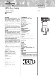
<strong>GESTRA</strong> <strong>Steam</strong> <strong>Systems</strong><br />
Control Terminal and Display Unit<br />
Type URB 1<br />
Product Range B<br />
URB 1<br />
System Description<br />
The URB 1 is a user-friendly control terminal and display<br />
unit for use with <strong>GESTRA</strong> CAN bus systems. With the<br />
URB 1 all standard functions of the CAN bus systems<br />
can be easily called up and adjusted. The URB 1 uses the<br />
CANopen protocol.<br />
Furthermore, the URB 1 makes the parameterization of the<br />
controller very convenient: The switchpoints, the response<br />
sensitivity and the proportional band can be adjusted by<br />
means of the keypad regardless of the actual values (level,<br />
conductivity). The energizing and deenergizing times of the<br />
relays can be customized for the switchpoints.<br />
The URB 1 features a continuous display and therefore<br />
meets the requirements of TRD 401 / EN 12952 and<br />
EN 12953 for a second water level indicator. The equipment<br />
has also a temperature-compensated conductivity<br />
indication as required by VdTÜV – Bulletin WÜ 100 (Water<br />
Level 100).<br />
The equipment indicates also malfunctions such as<br />
faulty electrode, excessively high temperature in a sensor,<br />
ambient temperature above max. limit, faulty communication<br />
etc.<br />
The following tables specify the <strong>GESTRA</strong> equipment that<br />
can be displayed by the URB 1:<br />
Standard display information Level Conductivity<br />
NRS 1-40 NRS 1-41 NRS 1-42 NRS 2-40 NRR 2-40 LRR 1-40<br />
Actual value (bar chart) ● ● ●<br />
Actual value (numerical value) ● ● ●<br />
Switchpoint (symbol) ● ● ● ●<br />
High level alarm (electrode HW) ● ● ● ●<br />
Low level alarm (electrode LW) ● ● ● ●<br />
Manual/automatic operation ● ● ●<br />
Stand-by mode<br />
●<br />
Unit [µS/cm] or [ppm]<br />
●<br />
Low level limit<br />
●<br />
High level limit<br />
●<br />
Alarm (warning triangle) ● ●<br />
Further display information Level Conductivity<br />
NRS 1-40 NRS 1-41 NRS 1-42 NRS 2-40 NRR 2-40 LRR 1-40<br />
Actual value (continuous) ● ● ●<br />
Switchpoints ● ● ● ●<br />
Setpoint ● ●<br />
Deviation ● ●<br />
Valve position ● ●<br />
Intermittent blowdown<br />
●<br />
Intermittent blowdown interval<br />
●<br />
Purging pulse 24 h<br />
●<br />
Current CAN bus addresses ● ● ● ● ● ●<br />
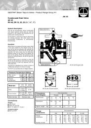
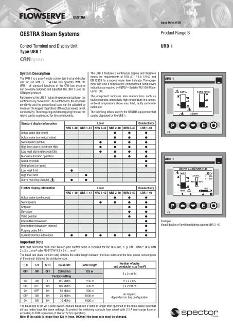
Example:<br />
Visual display of level monitoring system NRR 2-40<br />
Important Note<br />
Note that screened multi-core twisted-pair control cable is required for the BUS line, e. g. UNITRONIC ® BUS CAN<br />
2 x 2 x ... mm 2 oder RE-2YCYV-fl 2 x 2 x ... mm 2 .<br />
The baud rate (data transfer rate) dictates the cable length between the bus nodes and the total power consumption<br />
of the sensor dictates the conductor size.<br />
S 8 S 9 S 10 Baud rate Cable length<br />
Number of pairs<br />
and conductor size [mm 2 ]<br />
OFF ON OFF 250 kBit/s 125 m<br />
Factory setting<br />
2 x 2 x 0.34<br />
ON ON OFF 125 kBit/s 250 m 2 x 2 x 0.5<br />
OFF OFF ON 100 kBit/s 335 m 2 x 2 x 0.75<br />
ON OFF ON 50 kBit/s 500 m<br />
OFF ON ON 20 kBit/s 1000 m<br />
ON ON ON 10 kBit/s 1000 m<br />
on request,<br />
dependent on bus configuration<br />
The baud rate is set via a code switch. Reduce baud rate if cable is longer than specified in the table. Make sure that<br />
all bus nodes have the same settings. To protect the switching contacts fuse circuit with 2.5 A (anti-surge fuse) or<br />
according to TRD regulations (1.0 A for 72 hrs operation).<br />
Note: If the cable is longer than 125 m (max. 1000 m!) the baud rate must be changed.
Control Terminal and Display Unit<br />
Type URB 1<br />
Dimensions<br />
92 +0,8<br />
Function<br />
The URB 1 communicates with other <strong>GESTRA</strong> systems<br />
via a CAN bus to DIN ISO 11898 using CANopen protocol.<br />
Design<br />
URB 1<br />
Case according to DIN ISO 43700 for panel mounting.<br />
The terminals are accessible from the back.<br />
Installation in panel cut-out by means of fixing clips<br />
supplied with the equipment.<br />
Dimensions of panel cut-out:<br />
92 +0.8 mm x 92 +0.8 mm.<br />
CAN Bus<br />
All level and temperature switches, controllers and electrodes<br />
are interconnected by means of a CAN bus. The<br />
data exchange is effected by means of a CAN bus according<br />
to DIN ISO 11898 using the CANopen protocol. Every<br />
item of equipment features an electronic address (Node<br />
ID). The four-core bus cable serves as power supply and<br />
data highway for high-speed data exchange.<br />
URB 1 is configured at our works and ready for service<br />
with other <strong>GESTRA</strong> components.<br />
URB 1 can be used straight away without having to set<br />
the Node ID.<br />
Technical Data<br />
Type approval no.<br />
TÜV · WÜL · 02-007<br />
BAF-MUC 0205 103881 003<br />
Data exchange<br />
CAN bus to DIN ISO11898<br />
CANopen protocol<br />
Indicators and adjustors<br />
1 illuminated display,<br />
resolution: 128 x 64 pixels<br />
5 push buttons<br />
Supply voltage<br />
18 V – 36 V DC<br />
Protection<br />
Front panel: IP 54 to DIN EN 60529<br />
Back: IP 00 to DIN EN 60529<br />
Admissible ambient temperature<br />
0 °C – 55°C<br />
Case material<br />
Front face: Aluminium with polyester membrane<br />
Back: Noryl GFN 2 SE 1, glass-fibre reinforced<br />
Weight<br />
Approx. 0.3 kg<br />
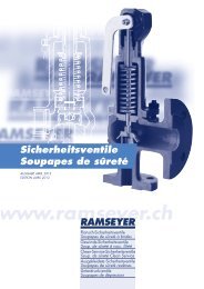
Wiring Diagram<br />
Bediengerät Control terminal<br />
URB 1<br />
- CL<br />
C L<br />
<br />
Terminating Abschlußwiderstand resistor 120 120 Ohm, Ω<br />
Paired Leitung cable paarig verseilt<br />
Level Niveauschalter switch<br />
NRS .…<br />
. .<br />
C H<br />
95<br />
S<br />
24V DC<br />
CAN - Bus<br />
URB 1<br />
_<br />
Conductivity Leitfähigkeitsregler<br />
controller LRR 1-40LRR 1-40<br />
1 2 3 4 5<br />
C L S C H +<br />
Conductivity Leitfähigkeitssonde<br />
electrode LRG 16-40 LRG 16-40<br />
Sensor Geber<br />
NRG ... …<br />
S CH<br />
+ ZEP CEP - CL<br />
S CH<br />
+ - CL<br />
S CH<br />
+ - CL<br />
S CH<br />
+ - CL<br />
S CH<br />
+<br />
95<br />
Code switch<br />
ON<br />
1 2 3<br />
92 +0,8<br />
BUS CAN 2 x 2 x...<br />
BUS CAN 2 x 2 x...<br />
63<br />
Order and Enquiry Specification<br />
<strong>GESTRA</strong> Control terminal and display unit type URB 1<br />
CANopen.<br />
Supply in accordance with our general terms<br />
of business.<br />
<br />
Supply Spannungsversorgung<br />
voltage<br />
Terminating Abschlußwiderstand resistor<br />
120 ΩOhm<br />
CAN data CAN-Datenleitung<br />
line<br />
Abschlußwiderstand<br />
Terminating resistor<br />
120 Ohm Ω<br />
<br />
<strong>GESTRA</strong> AG<br />
P. O. Box 10 54 60, D-28054 Bremen<br />
Münchener Str. 77, D-28215 Bremen<br />
Telephone +49 (0) 421 35 03 - 0, Fax +49 (0) 421 35 03-393<br />
E-Mail gestra.ag@flowserve.com, Internet www.gestra.de<br />
810374-05/906cm · 1998 <strong>GESTRA</strong> AG · Bremen · Printed in Germany