ZWR2MS-EFM - Elcon Systemtechnik
ZWR2MS-EFM - Elcon Systemtechnik
ZWR2MS-EFM - Elcon Systemtechnik

Erfolgreiche ePaper selbst erstellen
Machen Sie aus Ihren PDF Publikationen ein blätterbares Flipbook mit unserer einzigartigen Google optimierten e-Paper Software.
26<br />
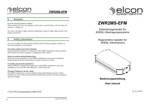
8 Remarks<br />
<strong>ZWR2MS</strong>-<strong>EFM</strong><br />
Keep this Operating Manual available!<br />
Before putting the device into operation, please make yourself familiar with the safety precautions<br />
(� Chapter 9).<br />
We reserve the right to apply technical modifications aimed to further improvement of the<br />
product performance.<br />
9 Safety precautions<br />
For your own safety, the following hints shall be observed. Please read them carefully, before<br />
you put the device into operation.<br />
Precautions against electrostatic discharge<br />
Upon opening and installation of components of the SHDSL transmission system, attention<br />
shall be paid to the safety precautions as stipulated by DIN 100 015.<br />
Safety precautions during thunderstorms<br />
Keep away from manipulations on the SHDSL transmission system and its components<br />
during thunderstorms (Do not disconnect or connect sub-units or cables).<br />
Grounding and potential equalization<br />
During installation, operation and maintenance of the SHDSL transmission system, the<br />
regulations as set out in DIN VDE 0800, part 2, shall be observed.<br />
Warning of dangerous electric voltage<br />
The SHDSL transmission system has interfaces being under dangerous electric voltage.<br />
Therefore, all works on the system should be performed by personnel who has the required<br />
special knowledge.<br />
© ELCON <strong>Systemtechnik</strong> GmbH 2010<br />
Version: 2010/03/19<br />
<strong>ZWR2MS</strong>-<strong>EFM</strong><br />
Zwischenregenerator für<br />
SHDSL-Übertragungssysteme<br />
Regenerative repeater for<br />
SHDSL transmissions<br />
Bedienungsanleitung<br />
User manual<br />
Art.-Nr. 102872
Deutsch: Seite 1<br />
English: Page 14<br />
<strong>ZWR2MS</strong>-<strong>EFM</strong> <strong>ZWR2MS</strong>-<strong>EFM</strong><br />
7 Technical data<br />
Version: 2010/03/19 Version: 2010/03/19<br />
DSL interface: as per ETSI TS 101 524 resp. ITU-T G.991.2<br />
Bit rate 192 kbps … 2304 kbps / 5696 kbps<br />
Line digit rate up to 773 1 / 3 kbaud / 1426 kbaud<br />
Line code TC-16-PAM / TC-32-PAM<br />
Impedance 135 �<br />
Degree of protection TNV3<br />
Power supply:<br />
Input voltage range of the local power supply -40.5 V to -75 V �<br />
Power consumption (local / remote powered) < 3 W / < 2.2 W<br />
Casing:<br />
Version Metal casing with integrated display elements<br />
and physical interfaces<br />
Display elements 2 LEDs for status indication<br />
Casing dimensions 109.4 × 194 × 30 mm 3 (W × D × H)<br />
Weight ca. 0.65 kg<br />
Environmental conditions: as per ETS 300 019<br />
Operation Air temperature: -25°C … +55°C<br />
Relative air humidity: 5% … 95%<br />
Storage Air temperature: -25°C … +55°C<br />
Relative air humidity: 10% … 100%<br />
Transport Air temperature: -25°C … +70°C<br />
Relative air humidity: 60% … 95%<br />
Standards:<br />
Safety EN 60 950-1<br />
Electromagnetic compatibility EN 55022, class B<br />
ITU-T K.21<br />
ETSI EN 300 386<br />
ETSI ES 201 468<br />
25
6 Display elements<br />
The <strong>ZWR2MS</strong>-<strong>EFM</strong> front panel offers 2 light-emitting diodes to signal the different operating<br />
states. Their meaning is determined in below table:<br />
LED Colour State Meaning<br />
ON green ON Local or remote power supply is applied to the <strong>ZWR2MS</strong>-<br />
<strong>EFM</strong>; Internal self test showed no faults<br />
blinking at<br />
1 Hz<br />
device is being initialized<br />
blinking at<br />
4 Hz<br />
Int-B-alarm set (Device PCB temperature exceeds 80°C)<br />
OFF No supply voltage<br />
DSL red ON SHDSL path is not connected, LOS, LOF<br />
blinking at<br />
4 Hz<br />
SHDSL line (DSL DSLAM-side) is being activated<br />
blinking at Waiting time between end of activation procedure at<br />
2 Hz DSLAM side and start of activation at CPE side<br />
blinking at SHDSL line (DSL CPE-side) is being activated or device is<br />
1 Hz being initialized<br />
flashing Maintenance function activated (SHDSL loop in<br />
every 5 s <strong>ZWR2MS</strong>-<strong>EFM</strong> closed or activation in diagnostics mode)<br />
flashes con- SHDSL section before <strong>ZWR2MS</strong>-<strong>EFM</strong> is being activated<br />
tinuously * (RSP signalling)<br />
flashes<br />
inverse<br />
at 1 Hz<br />
Line-Probing Session ongoing (PMMS)<br />
OFF Faultless data transmission<br />
* Signalling may occur also then if there is no physical link to the DSLAM<br />
Table 2: Meaning of the LED displays<br />
<strong>ZWR2MS</strong>-<strong>EFM</strong> 900260<br />
Figure 9: View of the front panel with LED display<br />
<strong>ZWR2MS</strong>-<strong>EFM</strong> <strong>ZWR2MS</strong>-<strong>EFM</strong><br />
Version: 2010/03/19 Version: 2010/03/19<br />
24 1<br />
Inhalt<br />
1. Kurzbeschreibung <strong>ZWR2MS</strong>-<strong>EFM</strong> 2<br />
2. Steckerbelegung 5<br />
3. Blockschaltbild <strong>ZWR2MS</strong>-<strong>EFM</strong> 8<br />
4. Bedienelemente (Option) 9<br />
5. Montage <strong>ZWR2MS</strong>-<strong>EFM</strong> in den Baugruppenträger 10<br />
6. Anzeigeelemente 11<br />
7. Technische Daten 12<br />
8. Hinweise 13<br />
9. Sicherheitshinweise 13
1 Kurzbeschreibung <strong>ZWR2MS</strong>-<strong>EFM</strong><br />
Der <strong>ZWR2MS</strong>-<strong>EFM</strong> dient z.B. der Reichweitenerhöhung des digitalen <strong>EFM</strong>-<br />
Übertragungssystems und kommt zum Einsatz, wenn die Leitungslänge zwischen dem<br />
DSLAM und dem Netzabschlussgerät (CPE) die maximale Reichweite der DSL-<br />
Schnittstelle überschreitet. <strong>ZWR2MS</strong>-<strong>EFM</strong> können auch innerhalb von <strong>EFM</strong>-Bonding-<br />
Gruppen (z.B. 4x <strong>ZWR2MS</strong>-<strong>EFM</strong> bei 4er SHDSL Bonding-Gruppe) eingesetzt werden.<br />
Mit einem <strong>ZWR2MS</strong>-<strong>EFM</strong> erzielt man eine Verdoppelung, mit zwei kaskadierten<br />
<strong>ZWR2MS</strong>-<strong>EFM</strong> eine Verdreifachung der Übertragungsreichweite eines SHDSL-Systems.<br />
Der Zwischenregenerator <strong>ZWR2MS</strong>-<strong>EFM</strong> ist mit zwei Kupferschnittstellen (DSL-<br />
Schnittstellen) ausgeführt, er regeneriert das gedämpfte, verzerrte Signal der ankommenden<br />
Impulsfolgen und leitet es dann weiter.<br />
Auf der DSL-Schnittstelle wird zur Datenübertragung ein TC-16-PAM- bzw. TC-32-PAMcodiertes<br />
Sendesignal verwendet. Die Übertragung erfolgt bidirektional über eine Doppelader<br />
(1-DA-System). Das anliegende Digitalsignal wird dabei transparent auf der SHDSL-<br />
Strecke durchgereicht. Die Sende- und Empfangsschaltung der Leitungsschnittstellen ist mit<br />
entsprechenden SHDSL-Transceivern mit Echokompensation realisiert. Die Übertragungsrate<br />
je Kupferdoppelader beträgt 2304 kBit/s (mit Leitungscode TC-16-PAM) bzw.<br />
5696 kBit/s (mit Leitungscode TC-32-PAM). Anpassungen der Bitrate werden entsprechend<br />
der verwendeten DSLAM-Konfiguration unterstützt.<br />
Das Übertragungssystem ist gemäß den Ausführungen der von ETSI herausgegebenen Technical<br />
Specification TS 101 524 bzw. ITU-T G.991.2 realisiert.<br />
Per SDSL-Overhead (EOC-Kanal) können optional verschiedene Einstellungen des<br />
<strong>ZWR2MS</strong>-<strong>EFM</strong> vom DSLAM oder auch CPE aus konfiguriert und Informationen (z.B.<br />
Performancedaten oder Temperatur) abgefragt werden. Auf diesem Weg ist optional auch<br />
ein Softwaredownload möglich.<br />
Die Versorgungsspannung des <strong>ZWR2MS</strong>-<strong>EFM</strong> wird aus der DSL-seitigen Fernspeisung<br />
abgeleitet, diese wird am DSLAM vom Fernspeisemodul FSP12AMS bereitgestellt. Weiterhin<br />
besteht die Möglichkeit, den <strong>ZWR2MS</strong>-<strong>EFM</strong> mit einer lokalen Speisespannung (z.B.<br />
mittels Speisemodul SPM) zu versorgen, wobei dann die Fernspeisung nicht mehr genutzt<br />
wird.<br />
Die Regenerator-Gehäuse sind als Metallkassetten für die Verwendung in einer ZWR-<br />
Aufnahme / in einem ZWR-Baugruppenträger BGT bzw. in einem<br />
Zwischenregeneratoreinsatz ZWRE für den KVz oder in einer Muffe ausgeführt. Es wird für<br />
einen <strong>ZWR2MS</strong>-<strong>EFM</strong> ein Steckplatz benötigt.<br />
<strong>ZWR2MS</strong>-<strong>EFM</strong> <strong>ZWR2MS</strong>-<strong>EFM</strong><br />
5 Assembly of <strong>ZWR2MS</strong>-<strong>EFM</strong> into the subrack<br />
For inserting the <strong>ZWR2MS</strong>-<strong>EFM</strong> into its slot, please use one guide rail. This permits to<br />
assemble up to six <strong>ZWR2MS</strong>-<strong>EFM</strong> per ZWR holder. When plugging the <strong>ZWR2MS</strong>-<strong>EFM</strong><br />
into the ZWR holder, make sure that the LEDs on front panel are on topside. The two pilots<br />
on the housing back side are used as reverse polarity protection. The metal bracket on the<br />
front of the repeater can be used for removing the unit from the slot.<br />
Commissioning<br />
After inserting the <strong>ZWR2MS</strong>-<strong>EFM</strong> into the corresponding slot, the device can be put into<br />
operation. Prerequisite for starting up the <strong>ZWR2MS</strong>-<strong>EFM</strong> is the applied local supply voltage<br />
or an activated FSP12AMS which has been plugged beside the DSLAM. The applied voltage<br />
is indicated through the green shining LED „ON“. Further, putting the device into operation<br />
additionally requires activation of the SHDSL transmission path from the DSLAM and<br />
CPE.<br />
1. The device is beginning with a self-test procedure in the first ca. 5 seconds. During<br />
this time all LEDs are blinking.<br />
2. After this the DSLAM is starting up the SHDSL line to the <strong>ZWR2MS</strong>-<strong>EFM</strong> (first<br />
transmission path section) and the red LED „DSL“ for the SHDSL link is blinking<br />
at a frequency of 4 Hz.<br />
3. After successful set-up of the first transmission path section, the red LED „DSL“<br />
for the SHDSL link is blinking with 1 Hz frequency. During this time the second<br />
transmission path section between the <strong>ZWR2MS</strong>-<strong>EFM</strong> and the CPE / the second<br />
<strong>ZWR2MS</strong>-<strong>EFM</strong> will be built-up.<br />
4. As for the <strong>ZWR2MS</strong>-<strong>EFM</strong>, the two ends of the transmission line have been set up<br />
when the red LED „DSL“ goes out.<br />
The <strong>ZWR2MS</strong>-<strong>EFM</strong> is controlled by the DSLAM and can be managed by the Network<br />
Management System (NMS).<br />
Special characteristic during the SHDSL Start-up<br />
Please take into account, that the restart time of an aborted SHDSL line could reach up to<br />
2 minutes by using one <strong>ZWR2MS</strong>-<strong>EFM</strong> and up to 4 minutes by using two repeaters in the<br />
SHDSL transmission path (the given time targets are defined by the ITU-/ ETSI standards<br />
ITU-T G.991.2 and ETSI TS 101 524). When using <strong>ZWR2MS</strong>-<strong>EFM</strong> within <strong>EFM</strong> bonding<br />
groups the resulting activation times might even be higher as Disocery and Aggregation<br />
phase times must be added.<br />
Version: 2010/03/19 Version: 2010/03/19<br />
2 23
4 Operating elements (Option)<br />
The switch on the circuit board allows to execute a configuration of the <strong>ZWR2MS</strong>-<strong>EFM</strong>.<br />
This switch is placed inside the device and becomes accessible after removing the casing<br />
bottom plate and the plastic protective plate. For this, release the four screws on the casing<br />
bottom, but do not pull them out. Make sure that the bow-shaped handle, the screws and the<br />
four distance sleeves, which are fixed on the screws on the casing bottom inside, will not go<br />
lost. The location of the switch and its position in default state can be seen in figure 8. The<br />
switch shall be operated by means of a suitable screwdriver (blade width approx. 3 mm).<br />
When changing the switch position, make sure to not damage the PCB lying beneath.<br />
The switch „RPS CONFIG“ allows to determine for the SHDSL, whether the remote power<br />
supply shall be transmitted to the next <strong>ZWR2MS</strong>-<strong>EFM</strong> (marking: „ “) or whether this shall<br />
not be executed (marking: „ “).<br />
After setting the switch, return the plastic protective plate onto the PCB. After this, fix the<br />
casing bottom plate by fastening the four screws, while at the same time inserting the bowshaped<br />
handle. Hereby it is mandatory that the distance sleeves are again seated on the<br />
thread ends of the screws. If either plastic protective plate or distance sleeves are missing,<br />
the circuit board is not reliably fixed, thus causing the danger of short circuit and body contact.<br />
Figure 8: Switch for setting the remote power supply (default setting)<br />
<strong>ZWR2MS</strong>-<strong>EFM</strong> <strong>ZWR2MS</strong>-<strong>EFM</strong><br />
1 Kurzbeschreibung <strong>ZWR2MS</strong>-<strong>EFM</strong>/ Fortsetzung<br />
Speisekonzept<br />
Der <strong>ZWR2MS</strong>-<strong>EFM</strong> kann mit lokaler Speisung oder mit Fernspeisung (DSLAM-seitig oder<br />
CPE-seitig) betrieben werden. Liegt eine lokale Speisespannung an (-40,5 V � ... -75 V �),<br />
so wird diese vom <strong>ZWR2MS</strong>-<strong>EFM</strong> verwendet, auch wenn noch zusätzlich eine Fernspeisespannung<br />
anliegt. Die lokale Speisung hat immer den Vorrang. Bei Fernspeisung wird der<br />
<strong>ZWR2MS</strong>-<strong>EFM</strong> über die Doppelader mit 112 V � (± 3 V �) vom Leitungsendgerät / Netzabschlussgerät<br />
aus gespeist. Eine Umschaltung zwischen DSLAM-seitiger und CPE-seitiger<br />
Fernspeisung ist nicht nötig. Wenn alle ZWR einer Linie die Durchspeisefunktion unterstützen,<br />
ist es möglich, die Fernspeisespannung zum nächsten <strong>ZWR2MS</strong>-<strong>EFM</strong> durchzureichen.<br />
Beispiele für den prinzipiellen Aufbau eines SHDSL-Systems mit einem Regenerator sowie<br />
mit zwei kaskadierten Regeneratoren werden in den nachfolgenden Bildern gezeigt.<br />
DSLAM<br />
mit FSP12<br />
Bild 1: Aufbau eines 1DA-SHDSL-Systems mit einem Regenerator <strong>ZWR2MS</strong>-<strong>EFM</strong> (Bsp.)<br />
DSLAM<br />
mit FSP12<br />
Bild 2: Aufbau zweier 1DA-SHDSL-Systeme mit je zwei kaskadierten Regeneratoren (Bsp.)<br />
Version: 2010/03/19 Version: 2010/03/19<br />
22 3<br />
DSL (1DA)<br />
Fernspeisung<br />
über DSL<br />
oder lokale<br />
Speisung<br />
(SPM - Option)<br />
DSL (1DA)<br />
Fernspeisung<br />
des <strong>ZWR2MS</strong>-<strong>EFM</strong> Nr. 1<br />
DSL (1DA)<br />
<strong>ZWR2MS</strong> CPE<br />
oder<br />
<strong>ZWR2MS</strong><br />
Nr. 1<br />
DSL (1DA)<br />
weitergeleitete<br />
Fernspeisung<br />
zur Speisung<br />
des <strong>ZWR2MS</strong>-<strong>EFM</strong> Nr. 2<br />
<strong>ZWR2MS</strong><br />
Nr. 2<br />
DSL (1DA)<br />
CPE
1 Kurzbeschreibung <strong>ZWR2MS</strong>-<strong>EFM</strong>/ Fortsetzung<br />
Ansichten<br />
Gehäuseboden<br />
Gehäuse<br />
Bügelgriff<br />
LED-Anzeige<br />
Bild 3: Ansicht der Gehäusefrontseite<br />
Gehäuse<br />
Positionierbolzen<br />
13-pol. Steckverbinder<br />
Bild 4: Ansicht Gehäuserückseite <strong>ZWR2MS</strong>-<strong>EFM</strong><br />
<strong>ZWR2MS</strong>-<strong>EFM</strong> <strong>ZWR2MS</strong>-<strong>EFM</strong><br />
3 Block diagram of <strong>ZWR2MS</strong>-<strong>EFM</strong><br />
The block diagram of the <strong>ZWR2MS</strong>-<strong>EFM</strong> is shown in figure 7. The device consists of the<br />
following function units:<br />
Microprocessor system<br />
consisting of microcontroller, SRAM and a FLASH.<br />
DSL interface connection (DSLAM, CPE)<br />
consisting of one dual SHDSL transceiver with corresponding I/O circuitry, with hybrid<br />
network, transmitters and protective elements.<br />
UB power supply interface<br />
The interface is short-circuit-proof, so that a reverse polarity would cause no response of the<br />
internal fuse, and no damage to the device / sub-unit. The supply voltage ranges from<br />
-40.5 V to -75 V.<br />
Figure 7: Block diagram of <strong>ZWR2MS</strong>-<strong>EFM</strong><br />
Version: 2010/03/19 Version: 2010/03/19<br />
4 21<br />
UB<br />
DSL<br />
Power pack<br />
DC / DC<br />
EMC<br />
Line<br />
interface<br />
Remote supply<br />
DC / DC<br />
AFE/DSP<br />
Option<br />
Controller &<br />
Peripheral<br />
Dual SHDSL Transceiver<br />
AFE/DSP<br />
Line<br />
interface<br />
EMC<br />
DSL
2 Interfaces/ continuation<br />
ZWR1<br />
ZWR2<br />
ZWR3<br />
ZWR4<br />
ZWR5<br />
ZWR6<br />
Figure 6: ZWR holder incl. six <strong>ZWR2MS</strong>-<strong>EFM</strong> and connector panel<br />
<strong>ZWR2MS</strong>-<strong>EFM</strong> <strong>ZWR2MS</strong>-<strong>EFM</strong><br />
2 Steckerbelegung<br />
Steckverbinder-Anschlussbelegung des <strong>ZWR2MS</strong>-<strong>EFM</strong><br />
Stiftleiste 1:<br />
2, 3 SHDSL-Anschluss in Richtung DSLAM<br />
7 FPE<br />
11, 12 Lokale Speisespannung im Bereich von -40,5 V � ... -75 V �<br />
11: Minuspotential<br />
12: Pluspotential<br />
Stiftleiste 2:<br />
7 FPE<br />
11, 12 SHDSL-Anschluss in Richtung CPE<br />
3 7 11<br />
2 12<br />
12<br />
Version: 2010/03/19 Version: 2010/03/19<br />
20 5<br />
1<br />
2<br />
11<br />
7<br />
Bild 5: Anschlussbelegung der Steckverbinder des <strong>ZWR2MS</strong>-<strong>EFM</strong>
2 Steckerbelegung/ Fortsetzung<br />
Belegung des Anschlussfelds der ZWR-Aufnahme<br />
PIN F1 an F1 ab<br />
� DSL zum CPE<br />
F2 an<br />
� DSL vom<br />
DSLAM<br />
<strong>ZWR2MS</strong>-<strong>EFM</strong> <strong>ZWR2MS</strong>-<strong>EFM</strong><br />
F2 ab<br />
� Stromversorgung<br />
1 a/b - DSL out (ZWR1) DSL in (ZWR1) a = + ; b = - (ZWR1)<br />
2 a/b - DSL out (ZWR2) DSL in (ZWR2) a = + ; b = - (ZWR2)<br />
3 a/b - DSL out (ZWR3) DSL in (ZWR3) a = + ; b = - (ZWR3)<br />
4 a/b - DSL out (ZWR4) DSL in (ZWR4) a = + ; b = - (ZWR4)<br />
5 a/b - DSL out (ZWR5) DSL in (ZWR5) a = + ; b = - (ZWR5)<br />
6 a/b - DSL out (ZWR6) DSL in (ZWR6) a = + ; b = - (ZWR6)<br />
Tabelle 1: Belegung des Anschlussfelds der ZWR-Aufnahme<br />
2 Interfaces/ continuation<br />
Pin assignment of connector panel of the ZWR holder<br />
PIN F1 an F1 ab<br />
� DSL to CPE<br />
F2 an<br />
� DSL from<br />
Version: 2010/03/19 Version: 2010/03/19<br />
6 19<br />
DSLAM<br />
F2 ab<br />
� Power supply<br />
1 a/b - DSL out (ZWR1) DSL in (ZWR1) a = + ; b = - (ZWR1)<br />
2 a/b - DSL out (ZWR2) DSL in (ZWR2) a = + ; b = - (ZWR2)<br />
3 a/b - DSL out (ZWR3) DSL in (ZWR3) a = + ; b = - (ZWR3)<br />
4 a/b - DSL out (ZWR4) DSL in (ZWR4) a = + ; b = - (ZWR4)<br />
5 a/b - DSL out (ZWR5) DSL in (ZWR5) a = + ; b = - (ZWR5)<br />
6 a/b - DSL out (ZWR6) DSL in (ZWR6) a = + ; b = - (ZWR6)<br />
Table 1: Pin assignment of connector panel of the ZWR holder
2 Interfaces<br />
Pin assignment of the <strong>ZWR2MS</strong>-<strong>EFM</strong><br />
Pin connector 1:<br />
2, 3 SHDSL connection in DSLAM direction<br />
7 FPE<br />
11, 12 Local supply voltage ranging from -40.5 V � ... -75 V �<br />
11: Negative potential<br />
12: Positive potential<br />
Pin connector 2:<br />
7 FPE<br />
11, 12 SHDSL connection in CPE direction<br />
1<br />
2<br />
3 7 11<br />
2 12<br />
12<br />
11<br />
7<br />
Figure 5: Connector pin assignment of the <strong>ZWR2MS</strong>-<strong>EFM</strong><br />
<strong>ZWR2MS</strong>-<strong>EFM</strong> <strong>ZWR2MS</strong>-<strong>EFM</strong><br />
2 Steckerbelegung/ Fortsetzung<br />
ZWR1<br />
ZWR2<br />
ZWR3<br />
ZWR4<br />
ZWR5<br />
ZWR6<br />
Bild 6: ZWR-Aufnahme mit sechs <strong>ZWR2MS</strong>-<strong>EFM</strong> und Anschlussfeld<br />
Version: 2010/03/19 Version: 2010/03/19<br />
18 7
3 Blockschaltbild <strong>ZWR2MS</strong>-<strong>EFM</strong><br />
Das Blockschaltbild der <strong>ZWR2MS</strong>-<strong>EFM</strong>-Baugruppe ist in Bild 7 gezeigt. Folgende Funktionsblöcke<br />
lassen sich unterscheiden:<br />
Mikroprozessorsystem<br />
bestehend aus Mikrokontroller, SRAM und FLASH.<br />
DSL Schnittstellenschaltung (DSLAM, CPE)<br />
bestehend aus einem 2-fach SHDSL-Transceiver mit entsprechender Ein- und Ausgangsbeschaltung<br />
mit Hybridnetzwerk, Übertragern und Schutzelementen.<br />
UB Stromversorgungsschnittstelle<br />
Die Schnittstelle ist kurzschlusssicher und eine Verpolung führt nicht zum Ansprechen der<br />
internen Sicherung bzw. zu einer Zerstörung des Gerätes / der Baugruppe. Der Speisespannungsbereich<br />
liegt im Bereich von -40,5 V bis -75 V.<br />
UB<br />
Netzteil<br />
DC / DC<br />
DSL Leitungs-<br />
EMV schnittstelle<br />
AFE/DSP<br />
Fernspeisung<br />
DC / DC<br />
Option<br />
Controller &<br />
Peripherie<br />
Dual SHDSL-Transceiver<br />
AFE/DSP<br />
Bild 7: Blockschaltbild <strong>ZWR2MS</strong>-<strong>EFM</strong><br />
<strong>ZWR2MS</strong>-<strong>EFM</strong> <strong>ZWR2MS</strong>-<strong>EFM</strong><br />
Leitungsschnittstelle<br />
EMV<br />
DSL<br />
1 Short description of <strong>ZWR2MS</strong>-<strong>EFM</strong>/ continuation<br />
Version: 2010/03/19 Version: 2010/03/19<br />
8 17<br />
Views<br />
Casing bottom plate<br />
Casing<br />
Metal bracket<br />
LED display<br />
Figure 3: View of the casing front side<br />
Casing<br />
Pilots<br />
13-pole connectors<br />
Figure 4: View of casing back side <strong>ZWR2MS</strong>-<strong>EFM</strong>
1 Short description of <strong>ZWR2MS</strong>-<strong>EFM</strong>/ continuation<br />
Supply concept<br />
The <strong>ZWR2MS</strong>-<strong>EFM</strong> can be either locally powered or operated with remote power supply<br />
(DSLAM-side or CPE-side). If local supply voltage is provided (-40.5 V � ...-75 V �), then<br />
the <strong>ZWR2MS</strong>-<strong>EFM</strong> makes use of it even under the condition remote power supply would be<br />
additionally applied. Local feeding always has priority over remote power supply if both of<br />
them are available. In case of remote power supply, the <strong>ZWR2MS</strong>-<strong>EFM</strong> is fed by the line<br />
terminating unit / network terminating unit through the twin wire with 112 V � (± 3 V �).<br />
Hereby it is not necessary to switch between DSLAM-side and CPE-side remote power<br />
supply. If all ZWR on a line support the power-through function, it is possible to transmit the<br />
remote power supply to the next <strong>ZWR2MS</strong>-<strong>EFM</strong>.<br />
The figures below show examples of the basic structure of an SHDSL system including one<br />
repeater, respectively, two cascaded repeaters.<br />
DSLAM<br />
with FSP12<br />
Figure 1: Structure of a 1DA-SHDSL system with one repeater <strong>ZWR2MS</strong>-<strong>EFM</strong> (example)<br />
DSLAM<br />
with FSP12<br />
DSL (1DA)<br />
Remote power<br />
supply via DSL<br />
or local<br />
powering<br />
(SPM - option)<br />
DSL (1DA)<br />
Remote power<br />
supply of the<br />
<strong>ZWR2MS</strong>-<strong>EFM</strong> no. 1<br />
DSL (1DA)<br />
<strong>ZWR2MS</strong> CPE<br />
or<br />
<strong>ZWR2MS</strong><br />
No. 1<br />
DSL (1DA)<br />
Forwarded<br />
remote power supply<br />
for powering the<br />
<strong>ZWR2MS</strong>-<strong>EFM</strong> no. 2<br />
<strong>ZWR2MS</strong><br />
No. 2<br />
Figure 2: Structure of two 1DA-SHDSL systems with two cascaded repeaters per system<br />
(example)<br />
<strong>ZWR2MS</strong>-<strong>EFM</strong> <strong>ZWR2MS</strong>-<strong>EFM</strong><br />
DSL (1DA)<br />
CPE<br />
4 Bedienelemente (Option)<br />
Mit dem auf der Leiterplatte befindlichen Umschalter kann eine Konfiguration des<br />
<strong>ZWR2MS</strong>-<strong>EFM</strong> vorgenommen werden. Dieser befindet sich im Inneren des Gerätes und ist<br />
nach Entfernen des Gehäusebodens und der Kunststoffschutzplatte zugänglich. Dazu sind<br />
die vier Schrauben auf der Gehäuseunterseite zu lösen (nicht herausziehen). Stellen Sie<br />
sicher, dass der Bügelgriff sowie die Schrauben und die vier Abstandshülsen, welche auf der<br />
Innenseite des Gehäusebodens auf den Schrauben stecken, nicht verloren gehen. Die Position<br />
des Schalters sowie dessen Stellung zum Zeitpunkt der Auslieferung können Sie Bild 8<br />
entnehmen. Zur Bedienung des Schaltelements muss ein geeigneter Schraubendreher (Klingenbreite<br />
ca. 3 mm) benutzt werden. Achten Sie beim Ändern der Schalterposition darauf,<br />
Leiterzüge und Bauelemente der darunter befindlichen Leiterplatte nicht zu beschädigen.<br />
Mit dem Umschalter „RPS CONFIG“ wird für die SHDSL-Strecke festgelegt, ob die Fernspeisung<br />
zum nächsten <strong>ZWR2MS</strong>-<strong>EFM</strong> durchgereicht werden soll (Kennzeichnung: „ “)<br />
oder ob die Fernspeisung nicht durchgereicht werden soll (Kennzeichnung: „ “).<br />
Legen Sie nach dem Einstellen des Schalters die Kunststoffschutzplatte wieder auf die Leiterplatte.<br />
Befestigen Sie anschließend den Gehäuseboden mit den vier Schrauben und setzen<br />
Sie gleichzeitig den Bügelgriff ein. Dabei müssen die Abstandshülsen unbedingt wieder auf<br />
den Gewindeenden der Schrauben stecken. Fehlen Kunststoffschutzplatte oder Abstandshülsen,<br />
ist die Leiterplatte nicht fixiert und es besteht Kurzschluss- bzw. Körperschlussgefahr.<br />
Bild 8: Umschalter für Fernspeisung (Auslieferungszustand)<br />
Version: 2010/03/19 Version: 2010/03/19<br />
16 9
5 Montage <strong>ZWR2MS</strong>-<strong>EFM</strong> in den Baugruppenträger<br />
Der <strong>ZWR2MS</strong>-<strong>EFM</strong> ist so in die ZWR-Aufnahme zu stecken, dass eine Führungsschiene<br />
genutzt wird. Damit lassen sich maximal sechs <strong>ZWR2MS</strong>-<strong>EFM</strong> pro ZWR-Aufnahme montieren.<br />
Achten Sie beim Einstecken des <strong>ZWR2MS</strong>-<strong>EFM</strong> in die ZWR-Aufnahme darauf, dass<br />
sich die LEDs auf der Frontseite oben befinden. Die beiden Positionierbolzen an der<br />
Gehäuserückseite dienen dabei zum Schutz gegen unbeabsichtigte Verpolung. Mittels des an<br />
der Vorderseite des Regenerators befindlichen Metallbügels kann das Gerät aus dem Einschubfach<br />
herausgezogen werden.<br />
Inbetriebnahme<br />
Nachdem der <strong>ZWR2MS</strong>-<strong>EFM</strong> in den entsprechenden Einschub gesteckt worden ist, kann das<br />
Gerät in Betrieb genommen werden. Zur Inbetriebnahme des <strong>ZWR2MS</strong>-<strong>EFM</strong> muss die<br />
lokale Versorgungsspannung anliegen bzw. am DSLAM / CPE ein FSP12AMS installiert<br />
und aktiviert sein. Das Vorhandensein einer Spannung wird durch das Leuchten der grünen<br />
LED „ON“ angezeigt. Eine weitere Voraussetzung für die Inbetriebnahme ist, dass die<br />
SHDSL-Übertragungsstrecke vom DSLAM und der CPE aktiviert wurde.<br />
1. Das Gerät durchläuft einen Autotest, der etwa 5 Sekunden dauert. Während dieser<br />
Zeit blinken alle LEDs.<br />
2. Anschließend beginnt der DSLAM mit dem Aufbau der SHDSL-Strecke zum<br />
<strong>ZWR2MS</strong>-<strong>EFM</strong> (erster Streckenabschnitt), wobei die rote LED „DSL“ der<br />
SHDSL-Übertragungsstrecke mit einer Frequenz von 4 Hz blinkt.<br />
3. Nach erfolgreichem Aufbau des ersten Streckenabschnitts blinkt die rote LED<br />
„DSL“ der Übertragungsstrecke mit einer Frequenz von 1 Hz, während dessen der<br />
zweite Streckenabschnitt zwischen dem <strong>ZWR2MS</strong>-<strong>EFM</strong> und dem CPE / dem<br />
zweiten <strong>ZWR2MS</strong>-<strong>EFM</strong> aufgebaut wird.<br />
4. Für den <strong>ZWR2MS</strong>-<strong>EFM</strong> sind beide Seiten der Übertragungsstrecke dann aufgebaut,<br />
wenn die rote LED „DSL“ erlischt.<br />
Der <strong>ZWR2MS</strong>-<strong>EFM</strong> wird durch den DSLAM gesteuert und kann optional vom Network<br />
Management System (NMS) gemanagt werden.<br />
Besonderheit beim Aufbau der SHDSL-Strecke<br />
Bitte beachten Sie, dass der Neustart einer ausgefallenen SHDSL-Strecke bis zu 2 Minuten –<br />
bei Nutzung eines <strong>ZWR2MS</strong>-<strong>EFM</strong> – und bis zu 4 Minuten – bei Nutzung von zwei Regeneratoren<br />
innerhalb der SHDSL-Übertragungsstrecke dauern kann (die zulässigen Zeiten sind<br />
in den ITU-/ ETSI-Standards ITU-T G.991.2 bzw. ETSI TS 101 524 festgelegt). Wenn<br />
<strong>ZWR2MS</strong>-<strong>EFM</strong> innerhalb von <strong>EFM</strong> Bonding-Gruppen eingesetzt werden, so können die<br />
reslutierenden Aktivierungszeiten sogar noch länger sein, da in diesem Fall Zeiten für Discovery<br />
und Aggregation Phasen hinzukommen.<br />
<strong>ZWR2MS</strong>-<strong>EFM</strong> <strong>ZWR2MS</strong>-<strong>EFM</strong><br />
1 Short description of <strong>ZWR2MS</strong>-<strong>EFM</strong><br />
The <strong>ZWR2MS</strong>-<strong>EFM</strong> has been developed e.g. to increase the range of the digital 2 Mbps<br />
transmission system and is used if the line length between the line terminating unit DSLAM<br />
and the network terminating unit CPE exceeds the maximum range of the DSL interface.<br />
<strong>ZWR2MS</strong>-<strong>EFM</strong> can also be used within <strong>EFM</strong> bonding groups (e.g. 4 ZWR per repeater<br />
place, when 4 SHDSL pairs are bonded).<br />
When using one <strong>ZWR2MS</strong>-<strong>EFM</strong> the range is doubled, whereas application of two cascaded<br />
<strong>ZWR2MS</strong>-<strong>EFM</strong> allows to triple the transmission range of the SHDSL system.<br />
The regenerative repeater <strong>ZWR2MS</strong>-<strong>EFM</strong> is equipped with two copper interfaces (DSL<br />
ports) and regenerates the attenuated and distorted signal of incoming pulse sequences and<br />
forwards it further.<br />
A TC-16-PAM- resp. TC-32-PAM-coded transmit signal is used for data transmission at the<br />
DSL interface. The bidirectional transmission runs over one twin wire (1-DA system). The<br />
supplied digital signal is transparently sent via the SHDSL path. The transmit-receive circuit<br />
at the line interfaces is implemented by adequate SHDSL transceivers using the echo compensation<br />
method. The line digit rate on the twin-wire copper line is 2304 kbps (with line<br />
code TC-16-PAM) resp. up to 5696 kbps (with line code TC-32-PAM). Fractional rates are<br />
supported according to DSLAM configuration.<br />
The transmission system has been implemented as required by the Technical Specification<br />
ETSI TS 101 524 resp. ITU-T G.991.2.<br />
Individual settings of the <strong>ZWR2MS</strong>-<strong>EFM</strong> can be optionally configured per SDSL-Overhead<br />
(EOC channel) from the DSLAM, which also provides the option to poll certain information<br />
(e.g. performance data or temperature). Optionally, the software can be downloaded this<br />
way, too.<br />
The supply voltage of the <strong>ZWR2MS</strong>-<strong>EFM</strong> is derived from the DSL-side remote power<br />
supply that is provided to the DSLAM resp. to the CPE by the remote power feeding module<br />
FSP12AMS. It is also possible to feed the <strong>ZWR2MS</strong>-<strong>EFM</strong> with a local supply voltage (e.g.<br />
by means of the power feeding module SPM), where in such case the remote power supply is<br />
not used any more.<br />
The repeater casings are designed as metallic cassettes for use in a ZWR holder / in a ZWR<br />
subrack BGT resp. a special repeater compartment ZWRE to be plugged into a cable junction<br />
box or into a sleeve. One <strong>ZWR2MS</strong>-<strong>EFM</strong> requires one slot.<br />
Version: 2010/03/19 Version: 2010/03/19<br />
10 15
Contents<br />
1. Short description of <strong>ZWR2MS</strong>-<strong>EFM</strong> 15<br />
2. Interfaces 18<br />
3. Block diagram of <strong>ZWR2MS</strong>-<strong>EFM</strong> 21<br />
4. Operating elements (Option) 22<br />
5. Assembly of <strong>ZWR2MS</strong>-<strong>EFM</strong> into the subrack 23<br />
6. Display elements 24<br />
7. Technical data 25<br />
8. Remarks 26<br />
9. Safety precautions 26<br />
<strong>ZWR2MS</strong>-<strong>EFM</strong> <strong>ZWR2MS</strong>-<strong>EFM</strong><br />
6 Anzeigeelemente<br />
An der Gerätefront des <strong>ZWR2MS</strong>-<strong>EFM</strong> befinden sich 2 Leuchtdioden, die die verschiedenen<br />
Betriebszustände signalisieren. Die Bedeutung ist in folgender Tabelle definiert:<br />
LED Farbe Zustand Bedeutung<br />
ON grün AN lokale oder Fernspeisung liegt am <strong>ZWR2MS</strong>-<strong>EFM</strong> an,<br />
interner Selbsttest wurde fehlerfrei durchlaufen<br />
blinkt mit<br />
1 Hz<br />
Gerät wird initialisiert<br />
blinkt mit<br />
4 Hz<br />
Int-B-Alarm aktiv (Gerätetemperatur ≥ 80°C)<br />
AUS keine Speisespannung<br />
DSL rot AN SHDSL-Strecke nicht angeschlossen, LOS, LOF<br />
blinkt mit<br />
4 Hz<br />
SHDSL-Strecke (DSL DSLAM-seitig) wird aktiviert<br />
blinkt mit Wartezeit zwischen Ende der Aktivierung zur DSLAM-<br />
2 Hz Seite und Beginn der CPE-seitigen Aktivierung<br />
blinkt mit SHDSL-Strecke (DSL CPE-seitig) wird aktiviert oder<br />
1 Hz Gerät wird initialisiert<br />
blitzt alle Maintenance-Funktion aktiv (SHDSL-Schleife im<br />
5 s<br />
<strong>ZWR2MS</strong>-<strong>EFM</strong> geschlossen oder Aktivierung erfolgte im<br />
Diagnostic-Mode)<br />
blitzt dau- vor dem <strong>ZWR2MS</strong>-<strong>EFM</strong> liegender SHDSL-Streckenernd<br />
kurz * abschnitt wird aktiviert (RSP-Signalisierung)<br />
blitzt invers<br />
mit 1 Hz<br />
Line-Probing Session aktiv (PMMS)<br />
AUS fehlerfreie Datenübertragung<br />
* Signalisierung kann auch auftreten, wenn keine physische Verbindung zum DSLAM besteht<br />
Tabelle 2: Bedeutung der LED-Anzeigen<br />
<strong>ZWR2MS</strong>-<strong>EFM</strong> 900260<br />
Bild 9: Frontansicht mit LED-Anzeige<br />
Version: 2010/03/19 Version: 2010/03/19<br />
14 11
7 Technische Daten<br />
DSL-Schnittstelle: entspr. ETSI TS 101 524 bzw. ITU-T G.991.2<br />
Bitrate 192 kBit/s … 2304 kBit/s / 5696 kBit/s<br />
Schrittgeschwindigkeit bis zu 773 1 / 3 kBaud / 1426 kBaud<br />
Leitungscode TC-16-PAM / TC-32-PAM<br />
Impedanz 135 �<br />
Sicherheitsgrad TNV3<br />
Stromversorgung:<br />
Eingangsspannungsbereich der Lokalspeisung -40,5 V bis -75 V �<br />
Leistungsaufnahme (lokal / ferngespeist) < 3 W / < 2.2 W<br />
Gehäuse:<br />
Ausführungsvariante Metallgehäuse mit integrierten Anzeige-<br />
elementen und physikalischen Schnittstellen<br />
Anzeigeelemente 2 LEDs zur Statusanzeige<br />
Gehäuseabmessungen 109,4 × 194 × 30 mm 3 (B × T × H)<br />
Gewicht ca. 0,65 kg<br />
Umweltbedingungen: entsprechend ETS 300 019<br />
Betrieb Lufttemperatur: -25°C … +55°C<br />
rel. Luftfeuchtigkeit: 5% … 95%<br />
Lagerung Lufttemperatur: -25°C … +55°C<br />
rel. Luftfeuchtigkeit: 10% … 100%<br />
Transport Lufttemperatur: -25°C … +70°C<br />
rel. Luftfeuchtigkeit: 60% … 95%<br />
Normen:<br />
Sicherheit EN 60 950-1<br />
EMV EN 55022, Kl. B<br />
ITU-T K.21<br />
ETSI EN 300 386<br />
ETSI ES 201 468<br />
<strong>ZWR2MS</strong>-<strong>EFM</strong> <strong>ZWR2MS</strong>-<strong>EFM</strong><br />
8 Hinweise<br />
Diese Anweisung aufbewahren!<br />
Bei Inbetriebnahme des Gerätes sind die Sicherheitshinweise zu beachten (� Kapitel 9).<br />
Technische Änderungen sind dem technischen Fortschritt geschuldet und dienen der Verbesserung<br />
des Gerätes.<br />
9 Sicherheitshinweise<br />
Folgende Sicherheitshinweise sind zu Ihrer Sicherheit zu befolgen. Lesen Sie diese, bevor<br />
Sie das Gerät in Betrieb nehmen.<br />
ESD-Schutzmaßnahmen<br />
Beim Öffnen und bei Einbau von Komponenten des SHDSL-Übertragungssystems sind die<br />
Schutzmaßnahmen nach DIN 100 015 zu beachten.<br />
Vorsichtsmaßnahmen bei Gewitter<br />
Vermeiden Sie Arbeiten am SHDSL-Übertragungssystem und dessen Komponenten bei<br />
Gewittertätigkeit (Ziehen und Stecken von Baugruppen bzw. Leitungen).<br />
Erde und Potentialausgleich<br />
Bei Installation, Betrieb und Wartung des SHDSL-Übertragungssystems ist die DIN VDE<br />
0800, Teil 2 zu beachten.<br />
Warnung vor gefährlicher elektrischer Spannung<br />
Das SHDSL-Übertragungssystem enthält Schnittstellen mit gefährlicher elektrischer Spannung.<br />
Alle Arbeiten am System sollten von Fachpersonal durchgeführt werden.<br />
Version: 2010/03/19 Version: 2010/03/19<br />
12 13