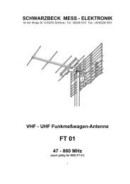
SCHWARZBECK MESS - ELEKTRONIK
SCHWARZBECK MESS - ELEKTRONIK
SCHWARZBECK MESS - ELEKTRONIK

Sie wollen auch ein ePaper? Erhöhen Sie die Reichweite Ihrer Titel.
YUMPU macht aus Druck-PDFs automatisch weboptimierte ePaper, die Google liebt.
<strong>SCHWARZBECK</strong> <strong>MESS</strong> – <strong>ELEKTRONIK</strong><br />
An der Klinge 29 D-69250 Schönau Tel.: 06228/1001 Fax.: (49)6228/1003<br />
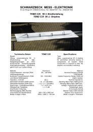
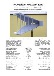
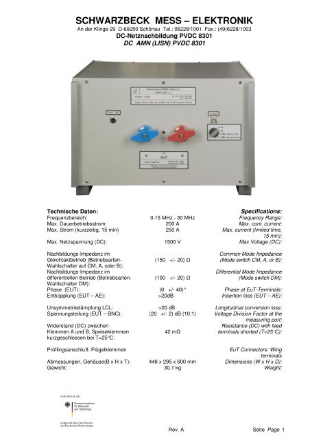
DC-Netznachbildung PVDC 8301<br />
DC AMN (LISN) PVDC 8301<br />
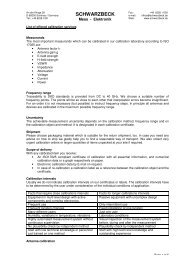
Technische Daten:<br />
Specifications:<br />
Frequenzbereich: 0.15 MHz - 30 MHz Frequency Range:<br />
Max. Dauerbetriebsstrom: 200 A Max. cont. current:<br />
Max. Strom (kurzzeitig, 15 min) 250 A Max. current (limited time,<br />
15 min):<br />
Max. Netzspannung (DC): 1500 V Max Voltage (DC):<br />
Nachbildungs-Impedanz im<br />
Gleichtaktbetrieb (Betriebsarten-<br />
Wahlschalter auf CM, A, oder B):<br />
Nachbildungs-Impedanz im<br />
differentiellen Betrieb (Betriebsarten-<br />
(150 +/- 20) Ω<br />
(100 +/- 20) Ω<br />
Common Mode Impedance<br />
(Mode switch CM, A, or B):<br />
Differential Mode Impedance<br />
(Mode switch DM):<br />
Wahlschalter DM):<br />
Phase (EUT): (0 +/- 40)° Phase at EuT-Terminals:<br />
Entkopplung (EUT – AE): >20dB Insertion loss (EUT – AE):<br />
Unsymmetriedämpfung LCL: >20 dB Longitudinal conversion loss:<br />
Spannungsteilung (EUT – BNC): (20 +/- 2) dB (10:1) Voltage Division Factor at the<br />
measuring port:<br />
Widerstand (DC) zwischen<br />
Klemmen A und B, Speiseklemmen<br />
kurzgeschlossen bei T=25°C:<br />
42 mΩ<br />
Resistance (DC) with feed<br />
terminals shorted (T=25°C):<br />
Prüflingsanschluß: Flügelklemmen<br />
EuT Connectors: Wing<br />
terminals<br />
Abmessungen, Gehäuse(B x H x T): 448 x 295 x 600 mm Dimensions (W x H x D):<br />
Gewicht: 30.1 kg Weight:<br />
Rev. A Seite Page 1
<strong>SCHWARZBECK</strong> <strong>MESS</strong> – <strong>ELEKTRONIK</strong><br />
An der Klinge 29 D-69250 Schönau Tel.: 06228/1001 Fax.: (49)6228/1003<br />
DC-Netznachbildung PVDC 8301<br />
DC AMN (LISN) PVDC 8301<br />
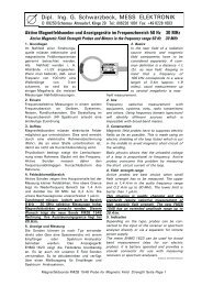
Einführung<br />
Bisher wurden bei Photovoltaikwechselrichtern<br />
lediglich wechselspannungsseitig mit 50 Ω<br />
V-Netznachbildungen gemäß CISPR 16-1-2 die<br />
unsymmetrische Störspannung gegen<br />
Bezugsmasse gemessen. Durch die üblichen<br />
Schaltungskonzepte von Wechselrichtern kommt<br />
es jedoch auch auf der DC-Seite zu<br />
hochfrequenten Stromwelligkeiten.<br />
Diese Rippelströme, die meist in festem<br />
Verhältnis zur Netzfrequenz stehen, können über<br />
die angeschlossenen PV-Module und deren<br />
Verkabelung als Magnetfelder abgestrahlt<br />
werden und zum Teil erhebliche Störfelder<br />
erzeugen. Messungen auf der AC-Seite bilden<br />
die oben genannten Störphänomene daher nur<br />
unzureichend ab.<br />
Für die Beurteilung der Störphänomene auf der<br />
Gleichspannungsseite von PV-Wechselrichtern<br />
wurde die PVDC 8301 entwickelt, die aufgrund<br />
ihres universellen Aufbaus sowohl die<br />
unsymmetrische Störspannung eines Leiters<br />
gegen Bezugsmasse, als auch die Gleichtakt-<br />
Störspannung eines Leiterpaars gegen<br />
Bezugsmasse (asymmetrische Störspannung),<br />
und letztlich auch die differentielle Störspannung<br />
zwischen zwei Leitern messen kann.<br />
Anwendung:<br />
Die symmetrische DC-Netznachbildung<br />
PVDC 8301 kann zum Messen der<br />
Störspannung im Frequenzbereich von 0.15 MHz<br />
bis 30 MHz auf Photovoltaik-Wechselrichtern<br />
verwendet werden. Sie ist mit eisenlosen<br />
Induktivitäten aufgebaut, um<br />
Intermodulationsstörungen zu vermeiden. Die<br />
zulässige Dauerstromaufnahme des Prüflings<br />
beträgt 200 A mit eingeschalteten Lüftern. Ohne<br />
Lüfter können 100 A Dauerstrom entnommen<br />
werden. Kurzzeitig können über 250 A<br />
entnommen werden.<br />
Die Temperatur der eingebauten Induktivitäten<br />
Introduction<br />
Up to now the conducted emissions of<br />
photovoltaic inverters at the mains terminals were<br />
usually measured using LISN according to<br />
CISPR 16-1-2. The circuit concepts of PVinverters<br />
may cause ripple currents on the DCside<br />
of the inverter, though. These ripple<br />
currents, which mostly are in direct proportion to<br />
the mains frequency, are passing through the<br />
cabling and the PV-generator modules and can<br />
be radiated as magnetic fields with sometimes<br />
remarkable disturbance effect. Traditional<br />
measurements at the PV-inverters' AC terminals<br />
will not be able to reveal such disturbance<br />
phenomena.<br />
The PVDC 8301 was especially designed to<br />
measure all kinds of disturbance voltages at the<br />
DC-side of photovoltaic inverters. These are in<br />
detail the disturbance voltage of one conductor<br />
above reference ground (unsymmetrical<br />
disturbance voltage), the common mode<br />
disturbance volage of a pair of conductors above<br />
ground (asymmetrical disturbance voltage) and<br />
finally, the differential mode voltage between two<br />
conductors.<br />
Application:<br />
The symmetric DC-LISN PVDC 8301 can be<br />
used for measuring the disturbance voltage in<br />
the frequency range from 0.15 MHz to 30 MHz on<br />
photovoltaic inverters. It is designed with air-core<br />
or iron-free inductors to prevent intermodulation.<br />
The permitted continuous current is 200 A with<br />
activated fans and 100 A without fans. The<br />
PVDC 8301 is able to handle 250 A for a short<br />
period of time.<br />
The temperature of the built in inductors may not<br />
Rev. A Seite Page 2
<strong>SCHWARZBECK</strong> <strong>MESS</strong> – <strong>ELEKTRONIK</strong><br />
An der Klinge 29 D-69250 Schönau Tel.: 06228/1001 Fax.: (49)6228/1003<br />
DC-Netznachbildung PVDC 8301<br />
DC AMN (LISN) PVDC 8301<br />
bei Strömen über 100 A darf 150°C nicht<br />
überschreiten.<br />
Der Prüfling wird an den Flügelklemmen des<br />
EUT-Anschlusses an der Frontplatte<br />
angeschlossen. Die Speisung erfolgt auf der<br />
Rückseite (AE).<br />
Der Kondensator C3 (Prinzipschaltbild) wurde<br />
auf einen Wert von 0.22 µF begrenzt, um<br />
mögliche Beeinflussung von Prüflingen zu<br />
minimieren. Die Entkopplung (EUT – AE) für<br />
Gegentaktsignale beträgt dadurch >20 dB. Wenn<br />
eine Entkopplung von mehr als 40 dB in DM<br />
gefordert wird, kann dies mit einem<br />
Zusatzkondensator von 0.1 µF / 1500 VDC an<br />
den AE-Klemmen erreicht werden.<br />
exceed 150°C.<br />
The device under test has to be connected to the<br />
wing terminals of the front panel. The PVgenerator<br />
or the PV-simulator is connected to the<br />
rear side.<br />
The capacitor C3 was limited to 0.22 µF to avoid<br />
possible interference to the EuT. This leads to a<br />
differential mode decoupling of more than 20 dB.<br />
If higher decoupling values are required (e.g. 40<br />
dB or more), one can use an additional<br />
0.1 µF / 1500 V DC capacitor at the AE-terminals.<br />
Prinzipschaltbild AMN PVDC 8301<br />
Simplified circuitry of the AMN PVDC 8301<br />
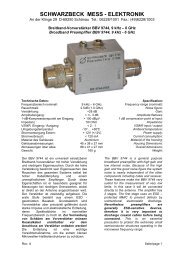
Störspannungsmessung<br />
Der Photovoltaik-Generatoranschluss (DC)<br />
erfolgt auf der Rückseite der PVDC 8301 (AE-<br />
Anschluss). Der Prüfling wird an der Vorderseite<br />
angeschlossen (EUT). Die HF-Störspannung, die<br />
der Prüfling emittiert, wird an die „Output“ BNC-<br />
Buchse ausgekoppelt, an der ein 50 Ω<br />
Messempfänger angeschlossen wird. Der<br />
Schalter auf der Vorderseite muss hierzu auf<br />
„DM differential mode“, „CM common mode“,<br />
„A“, oder „B“ gestellt werden.<br />
Interference Voltage measurements<br />
The photovoltaic generator or simulator must be<br />
connected to the rear side (AE) of the PVDC<br />
8301. The device under test (EUT) i.e. the DC<br />
input of a PV-inverter has to be connected to the<br />
terminals at the front panel. The RF interference<br />
voltage emitted by the DC-side of the inverter is<br />
decoupled at the ‘output’ BNC jack where it can<br />
be connected to a 50 Ω EMI receiver. The switch<br />
on the front panel must be set to „DM differential<br />
mode“, „CM common mode“, „A“, or „B“<br />
depending on the desired mode of measurement.<br />
Rev. A Seite Page 3
<strong>SCHWARZBECK</strong> <strong>MESS</strong> – <strong>ELEKTRONIK</strong><br />
An der Klinge 29 D-69250 Schönau Tel.: 06228/1001 Fax.: (49)6228/1003<br />
DC-Netznachbildung PVDC 8301<br />
DC AMN (LISN) PVDC 8301<br />
Mode A oder mode B: Die unsymmetrische<br />
Störspannung wird von der Klemme „A“ oder „B“<br />
zur Bezugsmasse gemessen<br />
(sog. V-Netznachbildung).<br />
Common mode (CM): es wird Summe der<br />
Störspannungen an den Klemmen „A“ und „B“<br />
gegen Bezugsmasse gemessen<br />
(sog. T-Netznachbildung, asymmetrische<br />
Störspannung oder Gleichtaktkomponente).<br />
In diesen drei Messarten beträgt die<br />
Eingangsimpedanz 150 Ω vom Prüfling aus<br />
gesehen.<br />
Differential mode (DM): es wird die<br />
symmetrische Störspannung zwischen Klemmen<br />
„A“ und „B“ gemessen. Die Impedanz beträgt<br />
dabei 100 Ω (sog. Delta-Netznachbildung,<br />
Gegentakt-Störspannung).<br />
Die HF-Bezugsmasse wird mit der GND-Klemme<br />
oder mit Aluminium - Winkeln auf der Rückseite<br />
verbunden.<br />
Mode A or mode B: The unsymmetrical<br />
interference voltage is measured from port „A“ or<br />
„B“ to RF-ground (V-LISN).<br />
Common mode (CM): The sum of interference<br />
voltage of port „A“ and „B“ is being measured<br />
against RF ground (T-LISN, asymmetrical<br />
disturbance voltage).<br />
In these three modes of measurement the input<br />
impedance seen from the device under test is<br />
150 Ω.<br />
Differential mode (DM): The symmetrical<br />
disturbance voltage between the terminals „A“<br />
und „B“ is being measured (Delta LISN). The<br />
impedance is 100 Ω in this case.<br />
The RF ground potential is being connected with<br />
the GND connector or with the aluminium bars on<br />
the rear panel.<br />
Hinweis:<br />
Die Netznachbildung muss vor der<br />
Netzverbindung an Schutzerde gelegt<br />
werden. Anwender der Netznachbildung sind<br />
entsprechend einzuweisen. Bei unsachgemäßer<br />
Anwendung besteht für den Benutzer<br />
Lebensgefahr!<br />
Die Speisespannung muss immer<br />
abgeschaltet werden, wenn Leitungen<br />
angeschlossen oder abgenommen werden<br />
müssen. Eine vorgeschaltete, leicht<br />
erreichbare Trennvorrichtung ist Pflicht!<br />
Auch wenn die Netznachbildung vollständig<br />
vom Speisenetz getrennt ist, können die<br />
verwendeten Kondensatoren Ladung über<br />
längere Zeit speichern. Es wird dringend<br />
empfohlen, vor Berührung der Klemmen<br />
eventuell vorhandene Restladung mit Hilfe<br />
eines isolierten Kabels gegen Masse<br />
abzuleiten. Aus technischen Gründen können<br />
keine Entladewiderstände eingebaut werden,<br />
da PV-Wechselrichter in der Regel beim<br />
Hochfahren diverse Isolationsbedingungen<br />
prüfen.<br />
Während des Betriebes ist immer auf freie<br />
Luftzufuhr von unten und auf freien Luftaustritt<br />
oben zu achten!<br />
Notice:<br />
In any case, ground-connect LISN before<br />
connecting to power line. Precise safety<br />
instructions must be provided to any user of the<br />
LISN. Inappropriate usage of the LISN may<br />
cause fatal harm!<br />
Always switch off the supply voltage before<br />
connecting or disconnecting terminals. An<br />
easily accessible circuit breaker before and<br />
behind the LISN is stringently required! The<br />
capacitors of the LISN can store charge over<br />
a long time, even if the LISN is completely<br />
disconnected from power supplies and EuT.<br />
We strongly recommend to discharge the<br />
capacitors using an isolated cable to ground<br />
before touching the terminals. For technical<br />
reasons it is not possible to use dischargeresistors,<br />
because the majority of GCPC (Grid<br />
Connected Power Conditioner) are testing<br />
several isolation conditions during start up.<br />
Air circulation must be possible at any time.<br />
Neither the top side nor the bottom side of the<br />
LISN may be covered during operation!<br />
Rev. A Seite Page 4
<strong>SCHWARZBECK</strong> <strong>MESS</strong> – <strong>ELEKTRONIK</strong><br />
An der Klinge 29 D-69250 Schönau Tel.: 06228/1001 Fax.: (49)6228/1003<br />
DC-Netznachbildung PVDC 8301<br />
DC AMN (LISN) PVDC 8301<br />
180<br />
Impedanz an den Prüflingsklemmen - common mode, mode A, B<br />
(Kalibrieradapter erforderlich), BNC mit 50 Ω Abschluss<br />
Impedance at EuT-Terminals (Calibration adapter required),<br />
BNC-Port is terminated with 50 Ω<br />
160<br />
140<br />
120<br />
Z [Ohm]<br />
100<br />
80<br />
60<br />
40<br />
AE short<br />
AE open<br />
20<br />
0<br />
0.01 0.1 1 10<br />
Frequency [MHz]<br />
30<br />
1800<br />
1600<br />
AE open<br />
AE short<br />
1400<br />
1200<br />
Z [Ohm]<br />
1000<br />
800<br />
600<br />
400<br />
200<br />
0<br />
0.001 0.01 0.1 1 10<br />
Frequency [MHz]<br />
30<br />
Rev. A Seite Page 5
<strong>SCHWARZBECK</strong> <strong>MESS</strong> – <strong>ELEKTRONIK</strong><br />
An der Klinge 29 D-69250 Schönau Tel.: 06228/1001 Fax.: (49)6228/1003<br />
DC-Netznachbildung PVDC 8301<br />
DC AMN (LISN) PVDC 8301<br />
Phase an den Prüflingsklemmen - common mode, mode A, B<br />
(Kalibrieradapter erforderlich), BNC mit 50 Ω Abschluss<br />
Phase at EuT-Terminals (Calibration adapter required),<br />
BNC-Port is terminated with 50 Ω<br />
80<br />
60<br />
40<br />
Phase [grad]<br />
20<br />
0<br />
-20<br />
-40<br />
-60<br />
-80<br />
AE short<br />
AE open<br />
0.001 0.01 0.1 1 10<br />
Frequency [MHz]<br />
30<br />
Rev. A Seite Page 6
<strong>SCHWARZBECK</strong> <strong>MESS</strong> – <strong>ELEKTRONIK</strong><br />
An der Klinge 29 D-69250 Schönau Tel.: 06228/1001 Fax.: (49)6228/1003<br />
DC-Netznachbildung PVDC 8301<br />
DC AMN (LISN) PVDC 8301<br />
Impedanz an den Prüflingsklemmen - differential mode<br />
(Kalibrieradapter erforderlich), BNC mit 50 Ω Abschluss<br />
Impedance at EuT-Terminals (Calibration adapter required),<br />
BNC-Port is terminated with 50 Ω<br />
140<br />
120<br />
100<br />
Z [Ohm]<br />
80<br />
60<br />
40<br />
AE short<br />
AE open<br />
20<br />
0<br />
0.01 0.1 1 10<br />
Frequency [MHz]<br />
30<br />
400<br />
350<br />
300<br />
Z [Ohm]<br />
250<br />
200<br />
150<br />
100<br />
50<br />
AE short<br />
AE open<br />
0<br />
0.001 0.01 0.1 1 10<br />
Frequency [MHz]<br />
30<br />
Rev. A Seite Page 7
<strong>SCHWARZBECK</strong> <strong>MESS</strong> – <strong>ELEKTRONIK</strong><br />
An der Klinge 29 D-69250 Schönau Tel.: 06228/1001 Fax.: (49)6228/1003<br />
DC-Netznachbildung PVDC 8301<br />
DC AMN (LISN) PVDC 8301<br />
Phase an den Prüflingsklemmen - differential mode, (Kalibrieradapter erforderlich),<br />
BNC mit 50 Ω Abschluss<br />
Phase at EuT-Terminals (Calibration adapter required),<br />
BNC-Port is terminated with 50 Ω<br />
80<br />
60<br />
40<br />
Phase [grad]<br />
20<br />
0<br />
-20<br />
-40<br />
-60<br />
-80<br />
AE short<br />
AE open<br />
0.001 0.01 0.1 1 10<br />
Frequency [MHz]<br />
30<br />
Spannungsteilungsmaß Prüflingsklemmen - BNC (Kalibrieradapter erforderlich)<br />
Voltage Division Ratio EuT-Terminals to BNC (Calibration adapter required)<br />
-10<br />
-20<br />
Voltage division ratio [dB]<br />
-30<br />
-40<br />
-50<br />
-60<br />
-70<br />
mode A/B, AE short<br />
mode A/B, AE open<br />
CM, AE short<br />
CM, AE open<br />
DM, AE open/short<br />
-80<br />
-90<br />
0.01 0.1 1 10<br />
Frequency [MHz]<br />
30<br />
Rev. A Seite Page 8
<strong>SCHWARZBECK</strong> <strong>MESS</strong> – <strong>ELEKTRONIK</strong><br />
An der Klinge 29 D-69250 Schönau Tel.: 06228/1001 Fax.: (49)6228/1003<br />
DC-Netznachbildung PVDC 8301<br />
DC AMN (LISN) PVDC 8301<br />
Entkopplung zwischen EuT und Speiseklemmen AE im 50 Ω System (CM) und in 100 Ω System (DM)<br />
Decoupling between EuT and Generator Terminals AE (50 Ω System for CM and 100 Ω system for DM)<br />
0<br />
-10<br />
Insertion loss [dB]<br />
-20<br />
-30<br />
-40<br />
-50<br />
-60<br />
CM common mode<br />
CM, 100nF at AE and GND<br />
CM, 1µF at AE and GND<br />
-70<br />
-80<br />
-90<br />
0.01 0.1 1 10<br />
Frequency [MHz]<br />
30<br />
0<br />
-10<br />
Insertion loss [dB]<br />
-20<br />
-30<br />
-40<br />
-50<br />
-60<br />
DM common mode<br />
DM with 100nF at AE<br />
DM with 1µF at AE<br />
-70<br />
-80<br />
-90<br />
0.01 0.1 1 10<br />
Frequency [MHz]<br />
30<br />
Rev. A Seite Page 9
<strong>SCHWARZBECK</strong> <strong>MESS</strong> – <strong>ELEKTRONIK</strong><br />
An der Klinge 29 D-69250 Schönau Tel.: 06228/1001 Fax.: (49)6228/1003<br />
DC-Netznachbildung PVDC 8301<br />
DC AMN (LISN) PVDC 8301<br />
Unsymmetriedämpfung (LCL)<br />
Longitudinal conversion loss LCL<br />
Measured according to CISPR 16-1-2<br />
0<br />
-10<br />
LCL [dB]<br />
-20<br />
-30<br />
-40<br />
-50<br />
-60<br />
-70<br />
-80<br />
mode A/B<br />
common mode CM<br />
differential mode DM<br />
-90<br />
0.01 0.1 1 10<br />
Frequency [MHz]<br />
30<br />
Erwärmungskurve bei Dauerstrombelastung<br />
Heat Up Characteristics for continuous Currents<br />
160<br />
140<br />
Temperature [°C]<br />
120<br />
100<br />
80<br />
60<br />
100A, Fans OFF<br />
200A, Fans ON<br />
250A, Fans ON<br />
40<br />
20<br />
0 10 20 30 40 50 60<br />
Time [min]<br />
Rev. A Seite Page 10