ST 1141 ST 1142 ST 1143 - Elreha
ST 1141 ST 1142 ST 1143 - Elreha
ST 1141 ST 1142 ST 1143 - Elreha

Erfolgreiche ePaper selbst erstellen
Machen Sie aus Ihren PDF Publikationen ein blätterbares Flipbook mit unserer einzigartigen Google optimierten e-Paper Software.
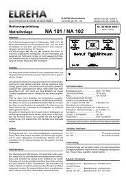
Kurzbeschreibung<br />
Die elektronischen Stufenschaltwerke<br />
der Serie <strong>ST</strong> 114x sind zur Ansteuerung<br />
von vier Kompressoren oder -stufen<br />
vorgesehen. Die Eingangsinformationen<br />
kommen von (je nach Typ)<br />
einem Pressostat und/oder einem<br />
Temperaturfühler. Dieses Gerät findet<br />
vor allem in Verbund-Kälteanlagen<br />
und in Klimaanlagen seinen Einsatz.<br />
Durch Anreihen von "Mutter"- und<br />
"Tochtergeräten" kann die Stufenzahl<br />
beliebig erweitert werden.<br />
Typenübersicht<br />
<strong>ST</strong> <strong>1143</strong> .......Standardgerät, 4 Stufen<br />
<strong>ST</strong> 1123 .......Standardgerät, 2 Stufen<br />
<strong>ST</strong> <strong>1143</strong> M ........................Muttergerät<br />
<strong>ST</strong> <strong>1143</strong> M/T ......... mittleres Gerät bei<br />
12-stufigem Ausbau<br />
<strong>ST</strong> <strong>1143</strong> T .......................Tochtergerät<br />
(letztes Gerät in der Kette)<br />
<strong>ST</strong> <strong>1141</strong> ..............zus. Fühlereingang,<br />
-30...+5°C / TF 102<br />
<strong>ST</strong> <strong>1141</strong> M/T ......... mittleres Gerät bei<br />
12-stufigem Ausbau<br />
<strong>ST</strong> <strong>1141</strong> T .......................Tochtergerät<br />
(letztes Gerät in der Kette)<br />
<strong>ST</strong> <strong>1142</strong> ..............zus. Fühlereingang,<br />
-5...+30°C / TF 101<br />
<strong>ST</strong> <strong>1142</strong> M/T ......... mittleres Gerät bei<br />
12-stufigem Ausbau<br />
<strong>ST</strong> <strong>1142</strong> T .......................Tochtergerät<br />
(letztes Gerät in der Kette)<br />
Funktion<br />
Eingangsinformation<br />
Der Regler erwartet, je nach Typ, einen<br />
Mittelstellungspressostaten (oder einen<br />
beliebigen potentialfreien Steuerkontakt)<br />
oder/und einen Temperaturfühler.<br />
Diese Sensoren liefern die Information,<br />
ob der Regler in den "Vorlauf", "Rücklauf"<br />
oder Beharrungszustand gehen<br />
soll. Dies wird jeweils durch die LED's<br />
"Vorlauf" und "Rücklauf" angezeigt, sind<br />
beide erloschen, befindet sich das <strong>ST</strong><br />
im Beharrungszustand (Neutralzone).<br />
Das Sollwertpotentiometer (nur<br />
<strong>1141</strong>/<strong>1142</strong>) hat eine Relativskala zur<br />
optischen Kontrolle, Rechts-/Linksanschlag<br />
entsprechen jeweils den<br />
in der Typenübersicht angegebenen<br />
Temperaturgrenzen.<br />
Vorlauf<br />
Vorlauf wird gefordert, wenn Klemmen<br />
3/5 gebrückt werden oder der mit dem<br />
Fühler gemessene Istwert den eingestellten<br />
um ca 1K überschreitet.<br />
Die Stufen werden dann in numerischer<br />
Reihenfolge nacheinander eingeschaltet.<br />
Bevor eine Stufe einschalten kann,<br />
muß erst die zugeordnete Vorlaufzeit<br />
abgelaufen sein. Erst wenn eine Stufe<br />
geschaltet hat, wird die Zeitverzögerung<br />
für die nachfolgende Stufe<br />
gestartet.<br />
Rücklauf<br />
Rücklauf wird gefordert, wenn Klemmen<br />
3/4 gebrückt sind oder sich die<br />
gemessene Temperatur unterhalb des<br />
Sollwertes befindet. Die Stufen schalten<br />
dann in umgekehrter Reihenfolge wieder<br />
ab, wobei für jede Stufe die eingestellte<br />
Rücklaufzeit wirksam wird.<br />
Neutralzone<br />
Ein Vor- oder Rücklaufsignal ist nicht<br />
vorhanden wenn weder die Klemmen<br />
3/4 noch 3/5 gebrückt sind oder die gemessenen<br />
Temperatur genau mit dem<br />
Sollwert übereinstimmt. In diesem Fall<br />
(Neutralzone) bleibt das Schaltwerk<br />
in einem Beharrungszustand, in dem<br />
Stufen weder ab- noch zugeschaltet<br />
werden.<br />
Brief Description<br />
The electronic stage controllers of the<br />
<strong>ST</strong> 114x series are suitable for controlling<br />
up to four compressor stages<br />
with time delays, depending on a<br />
request by a pressure switch (pressostat)<br />
and/or a temperature probe.<br />
The unit is mostly used in compound<br />
compressor systems for refrigeration<br />
or HVAC. By adding units in a ‘Master/Slave’-mode<br />
the number of stages<br />
can be increased in any way.<br />
Type Overview<br />
<strong>ST</strong> <strong>1143</strong> ........Standard Unit, 4 stages<br />
<strong>ST</strong> 1123 ........Standard Unit, 2 stages<br />
<strong>ST</strong> <strong>1143</strong> M ........................Master Unit<br />
<strong>ST</strong> <strong>1143</strong> M/T ............"middle" unit in a<br />
12-stage configuration<br />
<strong>ST</strong> <strong>1143</strong> T ...........................Slave Unit<br />
(last unit in a chain)<br />
<strong>ST</strong> <strong>1141</strong> additional temperature<br />
probe input (TF 102), -30...+5°C<br />
<strong>ST</strong> <strong>1141</strong> M/T ............"middle" unit in a<br />
12-stage configuration<br />
<strong>ST</strong> <strong>1141</strong> T ...........................Slave Unit<br />
(last unit in a chain)<br />
<strong>ST</strong> <strong>1142</strong> ......... additional temperature<br />
probe input (TF 101), -5...+30°C<br />
<strong>ST</strong> <strong>1142</strong> M/T ............"middle" unit in a<br />
12-stage configuration<br />
<strong>ST</strong> <strong>1142</strong> T ...........................Slave Unit<br />
(last unit in a chain)<br />
Function<br />
Input Information<br />
The controller expects, depending on<br />
type, a pressostat or another changeover<br />
switch with potential free contacts<br />
and/or a temperature probe.<br />
This sensors deliver the information to<br />
decide about the ‘Forward’ or ‘Backrun’-mode.<br />
The respective states are<br />
indicated by the LEDs "Forward" and<br />
"Backrun". If these LEDs are off, the<br />
<strong>ST</strong> runs in a "steady state" (neutral<br />
zone).<br />
The setpoint potentiometer (<strong>ST</strong><br />
<strong>1141</strong>/<strong>1142</strong> only) has a relative scale<br />
labeling, the start and end values depend<br />
on the <strong>ST</strong>-type.<br />
Forward Mode<br />
A forward signal is present if the terminals<br />
3/5 are connected or the temperature,<br />
measured by a probe, exceeds<br />
the setpoint by more than 1K.<br />
First a a forward delay timer starts.<br />
After this timer has been run down,<br />
the first output relay switches ON. As<br />
long as the forward signal is present,<br />
the timer will start again and the next<br />
relay switches in numeric order, and<br />
so on. The time delay of each stage<br />
can be adjusted on the front panel<br />
separately.<br />
Backrun Mode<br />
A backrun signal is present if the terminals<br />
3/4 are connected. The stages<br />
switch off in reverse order, the time<br />
delay of each stage can be adjusted<br />
individually as well.<br />
Neutral Zone<br />
Standstill or inertia occurs when the<br />
nominal value has been reached. The<br />
contacts of the pressostat are open<br />
(terminals 3/5 nor 3/4 connected).<br />
This means that, regardless of the<br />
step actually reached, no switching<br />
on or off is effected any longer.<br />
Bitte Sicherheitshinweise beachten!<br />
Please note Safety Instructions !<br />
Type:<br />
ELREHA<br />
ELEKTRONISCHE REGELUNGEN GMBH<br />
Betriebsanleitung 5310326-00/02<br />
Operating Instructions<br />
Stufenschaltwerk<br />
Compressor Stage Controller<br />
<strong>ST</strong> <strong>1141</strong><br />
<strong>ST</strong> <strong>1142</strong><br />
<strong>ST</strong> <strong>1143</strong><br />
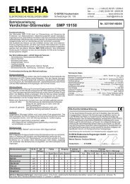
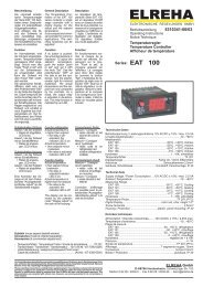
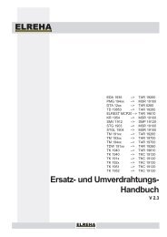
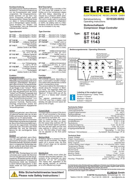
Bedienungselemente / Operating Elements<br />
Vorlaufverzögerung<br />
für jede Stufe<br />
Forward delay<br />
for each stage<br />
Rücklaufverz.<br />
für jede Stufe<br />
Backrun delay<br />
for each stage<br />
10`<br />
3" 1,5` 20`<br />
3" 3`<br />
1<br />
Schaltverzögerung<br />
10` 10` 10`<br />
3"<br />
1,5`<br />
20` 3"<br />
1,5`<br />
20` 3"<br />
1,5`<br />
20`<br />
3"<br />
LED leuchtet wenn Stufe<br />
zugeschaltet ist.<br />
LED ON if stage is<br />
engaged.<br />
2<br />
LED leuchtet wenn<br />
"Vorlauf" gefordert wird.<br />
LED ON if pressostat<br />
requests "forward"<br />
3` 3" 3` 3" 3`<br />
3 4<br />
ELEKTRONISCHES-<br />
<strong>ST</strong>UFENSCHALTWERK<br />
Labeling of the englisch types<br />
Schaltverzögerung = Delay Times<br />
Vorlauf = Forward<br />
Rücklauf = Backrun<br />
Sollwert = Setpoint<br />
Vorlauf<br />
Rücklauf<br />
Sollwert<br />
3<br />
4<br />
5<br />
2 6<br />
1 7<br />
LED leuchtet<br />
wenn<br />
"Rücklauf"<br />
gefordert<br />
wird.<br />
LED ON if<br />
pressostat<br />
requests<br />
"backrun"<br />
(nur <strong>1141</strong>/42)<br />
Linksanschlag<br />
=<br />
niedrigste<br />
Temperatur<br />
(<strong>1141</strong>/<strong>1142</strong><br />
only) left<br />
limit = lowest<br />
temperature<br />
Technische Daten<br />
Betriebsspannung ................................................................. 230V / 50Hz<br />
Leistungsaufnahme .............................................................. ca. 8VA max.<br />
Umgebungstemperatur ............................................................-10...+60°C<br />
Relaisausgänge .......................................................................potentialfrei<br />
Schaltleistung je Stufe ...................................................10A bei cos phi=1<br />
4 A induktiv 250V / 50Hz<br />
Temperaturbereich .................................................. siehe Typenübersicht<br />
Schaltdifferenz ...................................................................... 0,7K +/- 0,3K<br />
Neutralzone .......................................................................... 1,0K +/- 0,3K<br />
Vorlaufverzögerung ....................................................... 3 sec. bis 20 min.<br />
Rücklaufverzögerung ...................................................... 3 sec. bis 3 min.<br />
Eingangswiderstände ..................................... Spannungseing. >47kOhm<br />
Stromeing. 47kOhm<br />
Current Input
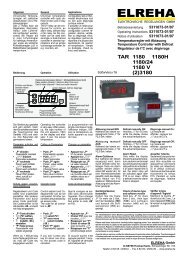
Seite 2 Betriebsanleitung/Manual <strong>ST</strong> <strong>1141</strong>- <strong>1143</strong><br />
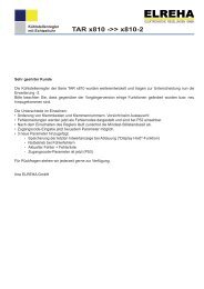
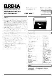
<strong>ST</strong> <strong>1143</strong> Abmessungen / Anschluss Dimensions / Connection<br />
180<br />
ELREHA<br />
3"<br />
1,5`<br />
20` 3"<br />
1,5`<br />
20` 3"<br />
1,5`<br />
20`<br />
3"<br />
Anschlußleiste 1<br />
1 2 3 4 5 6 7 8 9 10 3 4<br />
N L<br />
10`<br />
3" 1,5` 20`<br />
3" 3`<br />
1<br />
215<br />
Schaltv erzögerung<br />
10` 10` 10`<br />
Stufe Stufe Stufe Stufe<br />
1 2 3 4<br />
3` 3" 3` 3"<br />
2 3 4<br />
ELEKTRONISCHES-<br />
<strong>ST</strong>UFENSCHALTWERK<br />
Rückl.<br />
Vorl.<br />
3`<br />
Vorlauf<br />
Rücklauf<br />
Anschlußleiste 2<br />
5 6 7 8 9 10 11 12<br />
180<br />
ELREHA<br />
<strong>ST</strong> <strong>1141</strong> / <strong>1142</strong> Abmessungen / Anschluss Dimensions / Connection<br />
180<br />
ELREHA<br />
Anschlußleiste 1<br />
1 2 3 4 5 6 7 8 9 10 1 2 3 4<br />
N L<br />
10`<br />
3" 1,5` 20`<br />
3" 3`<br />
1<br />
3"<br />
1,5`<br />
20` 3"<br />
1,5`<br />
20` 3"<br />
1,5`<br />
20`<br />
3"<br />
Stufe Stufe Stufe Stufe<br />
1 2 3 4<br />
Installationshinweise<br />
215<br />
Schaltv erzögerung<br />
10` 10` 10`<br />
3` 3" 3` 3"<br />
2 3 4<br />
Temp.<br />
fühler<br />
Rückl.<br />
Vorl.<br />
3`<br />
ELEKTRONISCHES-<br />
<strong>ST</strong>UFENSCHALTWERK<br />
Vorlauf<br />
Rücklauf<br />
Sollwert<br />
3<br />
4<br />
5<br />
2 6<br />
1 7<br />
Anschlußleiste 2<br />
5 6 7 8 9 10 11 12<br />
Wird bei den Typen <strong>1141</strong>/<strong>1142</strong> nur der Temperaturfühler benutzt,<br />
müssen die Rücklaufklemmen 3/4 dauerhaft gebrückt werden.<br />
Werden mehrere Schaltwerke im Mutter/Tochterbetrieb aneinandergereit,<br />
müssen alle Schaltwerke gleichzeitig an Betriebsspannung liegen (siehe<br />
Verdrahtungspläne). Die Montage erfolgt unmittelbar nebeneinander, um die<br />
Verbindungsleitungen so kurz wie möglich zu halten. Sollte dies nicht möglich<br />
sein, dann müssen diese Verbindungen ebenfalls abgeschirmt werden.<br />
Notice<br />
N L<br />
10`<br />
3"<br />
1,5`<br />
20`<br />
3" 3`<br />
1<br />
3"<br />
1,5`<br />
20` 3"<br />
1,5`<br />
20` 3"<br />
1,5`<br />
20`<br />
3"<br />
215<br />
Delay Times<br />
10` 10`<br />
2 3<br />
1 2 3 4 5 6 7 8 9 10<br />
Stage Stage Stage Stage<br />
1 2 3 4<br />
english model<br />
Wird ausschließlich der<br />
Temperaturfühler verwendet,<br />
müssen die Klemmen<br />
3/4 (Rücklauf) dauerhaft<br />
gebrückt werden.<br />
If only a temperature probe<br />
is used, the terminals<br />
3/4 must be connected<br />
permanently.<br />
Installation HInts<br />
3` 3" 3` 3"<br />
ELECTRONIC<br />
<strong>ST</strong>EP CONTROLLER<br />
41<br />
10`<br />
4<br />
3`<br />
3 4 5 6 7 8 9 10 11 12<br />
3/4 = Backrun<br />
3/5 = Forward<br />
78<br />
Forward<br />
Backrun<br />
124,5<br />
If you use a temperature probe exclusively with the types <strong>1141</strong>/<strong>1142</strong>,<br />
the backrun terminals 3/4 must be bridged permanently.<br />
If several units must be cascaded for master/slave operation, mount them<br />
close side by side to ensure short wiring. All units must be supplied the same<br />
time (see sketches).
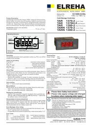
Betriebsanleitung/Manual <strong>ST</strong> <strong>1141</strong>- <strong>1143</strong> Seite 3<br />
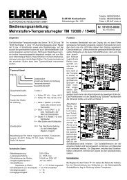
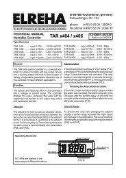
Verdrahtung Mutter/Tochtergeräte<br />
Wiring of Master/Slave Configurations<br />
1<br />
N<br />
Anschlussleiste/terminal 2 Anschlussleiste/terminal 2<br />
2 3 4 5 6 7 8 9 10 11 12<br />
1 2 3 4 5 6 7 8 9 10 11 12<br />
L<br />
Rückl.<br />
Vorl.<br />
Anreihen von 2 <strong>ST</strong> <strong>1143</strong> zu insgesamt 8 Stufen.<br />
Configuration of 2 <strong>ST</strong> <strong>1143</strong> with a total of 8 stages.<br />
Anreihen von 3 <strong>ST</strong> <strong>1143</strong> zu insgesamt 12 Stufen.<br />
Configuration of 3 <strong>ST</strong> <strong>1143</strong> with a total of 12 stages.<br />
<strong>ST</strong> <strong>1143</strong> M N L<br />
<strong>ST</strong> <strong>1143</strong> T<br />
Anschlussleiste/terminal 2 Anschlussleiste/terminal 2<br />
1 2 3 4 5 6 7 8 9 10 11 12 1 2 3 4 5 6 7 8 9 10 11 12<br />
N L N L<br />
Rückl.<br />
Vorl.<br />
<strong>ST</strong> <strong>1143</strong> M <strong>ST</strong> <strong>1143</strong> M/T<br />
Anschlussleiste/terminal 2<br />
1 2 3 4 5 6 7 8 9 10 11 12<br />
N L<br />
<strong>ST</strong> <strong>1143</strong> T
Betriebsanleitung/Manual <strong>ST</strong> <strong>1141</strong>- <strong>1143</strong> Seite 4<br />
ALLGEMEINE ANSCHLUSS- UND SICHERHEITSHINWEISE<br />
Diese Anleitung muss dem Nutzer jederzeit zugänglich sein.<br />
Bei Schäden, die durch unsachgemäße Handhabung oder<br />
Nichtbeachten der Anleitung und der Sicherheitshinweise<br />
verursacht werden, übernehmen wir keine Haftung! In solchen<br />
Fällen erlischt jeglicher Garantieanspruch.<br />
Falls Sie Beschädigungen feststellen, so darf das Produkt<br />
NICHT an Netzspannung angeschlossen werden!<br />
Es besteht Lebensgefahr!<br />
Ein sicherer Betrieb ist eventuell nicht mehr möglich wenn:<br />
• das Gerät sichtbare Beschädigungen aufweist,<br />
• das Gerät nicht mehr funktioniert,<br />
• nach längerer Lagerung unter ungünstigen Bedingungen,<br />
• starken Verschmutzungen oder Feuchtigkeit,<br />
• nach schweren Transportbeanspruchungen.<br />
• Die Installation und Inbetriebnahme des Gerätes darf<br />
nur durch eine Elektrofachkraft oder unter der Aufsicht<br />
einer Elektrofachkraft durchgeführt werden.<br />
• Halten Sie das Gerät bei der Montage sicher vom<br />
Stromnetz getrennt! Stromschlaggefahr!<br />
• Betreiben Sie das Gerät niemals ohne Gehäuse.<br />
Stromschlaggefahr!<br />
• Das Gerät darf nur für den auf Seite 1 beschriebenen<br />
Einsatzzweck verwendet werden.<br />
• Bitte beachten Sie die am Einsatzort vorgeschriebenen<br />
Sicherheitsvorschriften und Normen.<br />
• Bitte prüfen sie vor dem Einsatz des Reglers dessen<br />
technische Grenzen (siehe Technische Daten), z.B.:<br />
- Spannungsversorgung (auf dem Gerät aufgedruckt)<br />
- Vorgeschriebene Umgebungsbedingungen<br />
(Temperatur- bzw. Feuchtegrenzen)<br />
- Maximale Belastung der Relaiskontakte im Zusammenhang<br />
mit den maximalen Anlaufströmen der<br />
Last (z.B. Kompressoren).<br />
Bei Nichtbeachtung sind Fehlfunktionen oder<br />
Beschädigungen möglich.<br />
• Fühlerleitungen müssen abgeschirmt sein und dürfen<br />
nicht parallel zu netzführenden Leitungen verlegt werden.<br />
Die Abschirmung ist einseitig, möglichst nahe am Regler,<br />
zu erden. Wenn nicht, sind induktive Störungen möglich!<br />
• Bei Verlängerung von Fühlerkabeln beachten: Der Quer-<br />
schnitt ist unkritisch, sollte aber mind. 0,5mm² betragen.<br />
• Vermeiden Sie den Einbau in unmittelbarer Nähe von<br />
großen Schützen (starke Störeinstrahlung möglich).<br />
EG-Konformitätserklärung - EG-Conformity<br />
CONNECTION INFORMATION & SAFETY IN<strong>ST</strong>RUCTIONS<br />
The guarantee will lapse in case of damage caused by failure<br />
to comply with these operating instructions! We shall not be<br />
liable for any consequent loss! We do not accept liability for<br />
personal injury or damage to property caused by inadequate<br />
handling or non-observance of the safety instructions! The<br />
guarantee will lapse in such cases.<br />
If you notice any damage, the product may not be connected<br />
to mains voltage! Danger of Life!<br />
A riskless operation is impossible if:<br />
• The device has visible damages or doesn't work<br />
• After a long-time storage under unfavourable conditions<br />
• The device is strongly draggled or wet<br />
• After inadequate shipping conditions<br />
• Never use this product in equipment or systems that are<br />
intended to be used under such circumstances that may<br />
affect human life. For applications requiring extremely<br />
high reliability, please contact the manufacturer first.<br />
• The product may only be used for the applications<br />
described on page 1.<br />
• Electrical installation and putting into service must be<br />
done from qualified personnel.<br />
• During installation and wiring never work when the<br />
electricity is not cut-off ! Danger of electric shock!<br />
• Never operate unit without housing.<br />
Danger of electric shock!<br />
• Please note the safety instructions and standards of your<br />
place of installation!<br />
• Before installation: Check the limits of the controller and<br />
the application (see tech. data). Check amongst others:<br />
- Make sure that all wiring has been made in accordance<br />
with the wiring diagram in this manual.<br />
- Supply voltage (is printed on the type label).<br />
- Environmental limits for temperature/humidity.<br />
- Maximum admitted current rate for the relays. Compare<br />
it with the peak start-up currents of the controlled loads.<br />
Outside these limits malfunction or damages may occur.<br />
• Sensor/probe cables must be shielded. Don’t install them<br />
in parallel to high-current cables. Shielding must be<br />
connected to PE at the end close to the controller.<br />
If not, inductive interferences may occur.<br />
• Please note for elongation: The wire gauge is not critical,<br />
but should have 0,5mm² as a minimum.<br />
• Mounting the controller close to power relays is<br />
unfavourable. Strong electro-magnetic interference,<br />
malfunction may occur!<br />
Für das beschriebene Erzeugnis wird hiermit bestätigt, daß bei bestimmungsgemäßem Gebrauch die Anforderungen eingehalten<br />
werden, die in der Richtlinie des Rates zur Angleichung der Rechtsvorschriften der Mitgliedsstaaten über die elektromagnetische<br />
Verträglichkeit (2004/108/EG) und der Niederspannungsrichtlinie (2006/95/EG) festgelegt sind. Diese Erklärung gilt für alle Exemplare, auf die sich die vorliegende<br />
Bedienungsanleitung (die selbst Bestandteil dieser Erklärung ist) bezieht. Zur Beurteilung des Erzeugnisses hinsichtlich elektromagnetischer Verträglichkeit<br />
und der Niederspannungsrichtlinie wurden jeweils die aktuellen Ausgaben der betreffenden Grund- und Fachgrundnormen herangezogen.<br />
For all described products there is a declaration of conformity which describes that, when operated in accordance with the technical manual, the criteria have<br />
been met that are outlined in the guidelines of the council for alignment of statutory orders of the member states on EMC-Directive (2004/108/EC) and the<br />
Low Voltage Directive (LVD 2006/95/EC). This declarations are valid for those products covered by the technical manual which itself is part of the declaration.<br />
To meet the requirements, the currently valid versions of the relevant standards have been used.<br />
Diese Erklärung wird verantwortlich vom Hersteller/Importeur abgegeben durch:<br />
This statement is made from the manufacturer / importer by:<br />
ELREHA Elektronische Regelungen GmbH Werner Roemer, Technical Director<br />
D-68766 Hockenheim<br />
www.elreha.de Hockenheim.............21.09.2009.......................................................<br />
(Name / Anschrift / name / adress) Ort / city Datum / date Unterschrift / sign<br />
Diese Anleitung haben wir mit größter Sorgfalt erstellt, Fehler können wir aber nie ganz ausschließen. Unsere Produkte sind einer ständigen Pflege unterworfen,<br />
Änderungen der Konstruktion sind also möglich und vorbehalten.<br />
erstellt: 21.9.09, tkd/jr geprüft: 21.9.09, kd/mh freigegeben: 21.9.09, mkt/sha transl.(E): 21.9.09, tkd/jr transl()................