TAR 1180 1180H 1180/24 1180 V (2)3180 - Elreha
TAR 1180 1180H 1180/24 1180 V (2)3180 - Elreha
TAR 1180 1180H 1180/24 1180 V (2)3180 - Elreha

Erfolgreiche ePaper selbst erstellen
Machen Sie aus Ihren PDF Publikationen ein blätterbares Flipbook mit unserer einzigartigen Google optimierten e-Paper Software.
General<br />
Universal temperature<br />
controller with cyclic defrost<br />
function and 2 relay<br />
outputs.<br />
The 2nd Allgemein<br />
Applications<br />
Universeller Tempera-<br />
Ce régulateur est un therturregler<br />
mit zyklischer<br />
mostat électronique tout<br />
Abtaufunktion und 2 Re-<br />
ou rien avec dégivrage<br />
laisausgängen.<br />
cyclique naturel.<br />
Das 2. Relais kann als relay can be con- Il possède un relais pour<br />
Regelrelais, Warnrelais, figured for control, as la régulation et un relais<br />
Abtau- oder Lüfterre- alarm relay, defrost relay configurable comme rélais<br />
konfiguriert werden, or fan relay. So this congulation, alarme, ventila-<br />
sodaß der Regler als troller can be used both teur ou dégivrage. Ainsi,<br />
2- oder 3-Punktregler as single- or dual channel ce régulateur permet de<br />
für beliebige Anwendun- controller in standard ap- répondre à la plupart des<br />
gen sowie als einfacher plications and as simple applications de gestion<br />
Kühlstellenregler (z.B. in cold storage controller, for en température : simple<br />
Bedientheken) eingesetzt e.g. counters, etc. ou bi-étagés, chaud ou<br />
werden kann.<br />
froid, avec alarme...<br />
Bedienung<br />
Erhöhen von Werten<br />
Increase values<br />
Touche pour<br />
augmenter<br />
Verringern<br />
von Werten<br />
Decrease values<br />
Touche pour diminuer<br />
Die Bedienung gestaltet<br />
sich sehr einfach. Nach<br />
dem Einschalten erscheint<br />
die Typennummer des<br />
Gerätes (180) und nach<br />
ca. drei Sekunden der<br />
gemessene Istwert.<br />
Parameter aufrufen und<br />
verändern<br />
• „P“ drücken<br />
ParameterNr. erscheint<br />
• „�/�“ drücken<br />
Parameter auswählen<br />
• „P“ nochmals<br />
Param.wert sichtbar<br />
• „�/�“ drücken<br />
Param.wert verändern<br />
• „P“ nochmals<br />
Neuer Wert gespeichert,<br />
zurück zur<br />
Parameter-Nr.<br />
Schutz gegen unautorisierte<br />
Bedienung<br />
Regelsollwert und Code<br />
selbst sind ungehindert<br />
einstellbar. Alle anderen<br />
Parameter sind durch<br />
einen Code geschützt.<br />
Die Codenummer ist für<br />
alle Geräte --88-- und wird<br />
wie folgt eingegeben:<br />
• „P“-Taste drücken<br />
• �/� P21 wählen,<br />
• „P“-Taste erneut,<br />
• � CodeNr. ( 88 )<br />
einstellen.<br />
• "P"-Taste erneut,<br />
ParameterNr. wird<br />
wieder angezeigt<br />
Wenn ca. 1 Minute lang<br />
keine Taste gedrückt wurde,<br />
muß der Code neu<br />
eingegeben werden.<br />
Operation<br />
Operating the controller<br />
is very easy. After powerup,<br />
the type number of<br />
the unit appears (180)<br />
on the display and after<br />
appr. 3 sec. the actual<br />
temperature.<br />
Calling up Parameters<br />
• Push „P“<br />
ParameterNo. appears<br />
• Push „�/�“<br />
Select parameter<br />
• Push „P“ again<br />
Param. value visible<br />
• Push „�/�“<br />
Change Param.value<br />
• Push „P“ again<br />
New value is stored,<br />
back to parameter-no.<br />
Operator Code<br />
Control setpoint and Codeparameter<br />
can be set<br />
unimpeded. All other parameters<br />
are protected by<br />
an access code.<br />
The code for all controllers<br />
is „88“:<br />
• Push „P“<br />
• �/�select P21<br />
• "P" once more<br />
• � select CodeNo.<br />
( 88 )<br />
• Push "P" again<br />
ParameterNo. appears<br />
If you don´t press any<br />
key for about one minute,<br />
the access code is<br />
canceled.<br />
Utilisation<br />
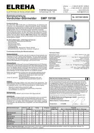
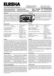
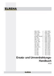
Relaiszustandsanzeige (blinken = Mindeststillstandszeit läuft)<br />
Relay position (blinking = Minimum Stop-Time runs)<br />
Etat du relais (clignote = l‘anti-court cycle s‘écoule)<br />
ein/on= Abtauen, defrost, dégivrage<br />
1<br />
<strong>TAR</strong><br />
2 3<br />
ELREHA<br />
P<br />
Programmiertaste<br />
Programming mode<br />
Touche de programmation<br />
ein/on=<br />
Relais 2 ein<br />
relay 2 ON<br />
blinken=<br />
Alarmwiederholzeit läuft<br />
blinking=<br />
alarm repeat time runs<br />
Clignote = tempo. répétit°<br />
alarme active<br />
La programmation est<br />
simple. A la mise en route,<br />
l‘afficheur indique „180“<br />
puis la température actuelle<br />
apparaît au bout<br />
de 3 sec..<br />
Changer un paramètre<br />
• Appuyer sur „P“<br />
N° du param. apparaît<br />
• Appuyer sur „�/�“<br />
Choisir le paramètre<br />
• Réappuyer sur „P“<br />
La valeur apparaît<br />
• Appuyer sur „�/�“<br />
Modifier la valeur<br />
• Réappuyer sur „P“<br />
La nouvelle valeur est<br />
validée, retour au n°<br />
du paramètre.<br />
Code de déverrouillage<br />
Seul la consigne se modifie<br />
sans déverrouiller<br />
l‘appareil. Pour changer<br />
les autres paramètres, il<br />
faut entrer le code „88“<br />
en P21.<br />
• Appuyer sur „P“<br />
• Choisir P21 avec les<br />
touches „�/�“<br />
• Réappuyer sur "P"<br />
• Entrer la valeur 88<br />
avec la touche „�".<br />
• Réappuyer sur "P"<br />
Déverrouillage activé<br />
Si aucune touche n‘est<br />
appuyée pendant 1 minute,<br />
l‘appareil se vérrouille<br />
automatiquement.<br />
SoftwVers.r16<br />
Abtauung manuell EIN<br />
Während der Istwert angezeigt<br />
wird, Taste „�" für<br />
>2,5 Sek. halten.<br />
Abtauung manuell<br />
AUS<br />
Während der Istwert angezeigt<br />
wird, Taste „�" für<br />
>2,5 Sek. halten.<br />
Alarm Quittieren<br />
Nur während der Istwert<br />
angezeigt wird, kann<br />
durch Drücken einer beliebigen<br />
Taste ein Alarm<br />
quittiert werden (Warnrelais<br />
fällt wieder ab). Ist<br />
eine Alarmwiederholzeit<br />
gewählt, zieht das Relais<br />
nach Ablauf von P15<br />
wieder an. Während einer<br />
Abtauung wird der Alarmtimer<br />
gestoppt.<br />
Gerätetyp/Version<br />
feststellen<br />
Halten Sie die Taste<br />
„P“ für mehr als 2 Sek.,<br />
wird der Gerätetyp (180)<br />
und danach die Softwareversion<br />
(r16) angezeigt.<br />
ELEKTRONISCHE REGELUNGEN GMBH<br />
Betriebssanleitung 5311073-01/07<br />
Operating instructions 5311073-01/07<br />
Notice d‘utilisation 5311073-01/07<br />
Temperaturregler mit Abtauung<br />
Temperature Controller with Defrost<br />
Régulateur de t°C avec dégivrage<br />
<strong>TAR</strong> <strong>1180</strong> <strong>1180</strong>H<br />
<strong>1180</strong>/<strong>24</strong><br />
<strong>1180</strong> V<br />
(2)<strong>3180</strong><br />
Defrost manually ON<br />
Hold key „�" for >2,5 sec<br />
while the display shows<br />
the actual temperature.<br />
Defrost manually OFF<br />
Hold key „�" for >2,5 sec<br />
while the display shows<br />
the actual temperature.<br />
Alarm Reset<br />
Only while the display<br />
shows the actual temperature,<br />
an alarm can be reset<br />
by pushing any key (alarm<br />
relay will be de-activated).<br />
If an alarm repeat time is<br />
set, the alarm relay will<br />
be activated again after<br />
P15 is run down. While<br />
a defrost event the alarm<br />
timer is stopped.<br />
Check of device type<br />
and software version<br />
Hold key „P“ for more<br />
than 2 sec., then type<br />
(180) and software<br />
version (r16) will be<br />
displayed.<br />
Dégivrage manuel On :<br />
La mesure est<br />
affichée ; appuyer sur<br />
„�" plus de 2,5 s.<br />
Dégivrage manuel Off :<br />
La mesure est<br />
affichée ; appuyer sur<br />
„�" plus de 2,5 s.<br />
Acquitter l‘alarme<br />
Seulement lorsque la mesure<br />
est affichée, l‘alarme<br />
peut être acquittée en<br />
appuyant sur une touche<br />
(le relais est désactivé).<br />
Si le défaut continue,<br />
l‘alarme se réactive après<br />
écoulement du temps<br />
P15. Pendant un cycle<br />
de dégivrage, l‘alarme<br />
est coupée.<br />
Vérifier le type<br />
d’appareil / logiciel<br />
Maintenir la touche „P“<br />
durant plus de 2 sec., Le<br />
type d’appareil (180) puis<br />
la version du logiciel (r16)<br />
apparaît.<br />
Vor Inbetriebnahme diese Bedienungsanleitung sorgfältig lesen! Entstehen durch Nichtbeachtung<br />
Schäden, erlöschen die Garantieansprüche. Diese Dokumentation würde mit größter Sorgfalt erstellt.<br />
Dennoch können wir für die vollständige Richtigkeit keine Garantie übernehmen.<br />
Please read these instructions carefully before applying power. Your attention is drawn to the fact<br />
that the warranty is subject to the application of power sources that are within the limits specified in<br />
this manual. Repairs or modifications made by anyone other than ELREHA will also void the product<br />
warranty. This documentation was compiled with utmost care, however, we cannot guarantee for its<br />
correctnesss in every respect.<br />
Avant la mise en service, veuillez lire attentivement la présente notice d‘utilisation. Tout dommage dû<br />
à l‘inobservation de nos instructions n‘est pas couvert par notre garantie. La présente documentation<br />
a été réalisée avec le plus grand soin, mais le risque d‘erreurs subsiste malgré tout.<br />
ELREHA Gmbh<br />
D-68766 Hockenheim, Schwetzinger Str. 103<br />
Telefon 0 62 05 / 2009-0 - Fax 0 62 05 / 2009-39 - www.elreha.de
Parameter und deren Bedeutung<br />
P01 .......Istwert am Regelfühler in °C /°F (nur Anz.)<br />
*P02 .....Regelsollwert 1, kein Code nötig.<br />
Wirkt auf Relais K1, Bereich P04...P05<br />
P03 .......Schalthysterese von P02<br />
Bereich 2...20K [2K]<br />
P04 .......Größter einstellbarer Regelsollwert<br />
Bereich -50..+100°C (-58..212°F),<br />
gilt nur für P02. [+100°C]<br />
P05 .......Kleinster einstellbarer Regelsollwert<br />
Bereich -50°C/-58°F...P04. [-50°C]<br />
P06 .......Schaltverhalten der Relais<br />
! Nur verstellbar mit Code 70 !<br />
Nicht verfügbar für <strong>TAR</strong> <strong>1180</strong> H<br />
• Kühlen = Relais zieht bei steigender<br />
Temperatur an<br />
• Kühlen relativ = Relais zieht bei steigender<br />
Temperatur an, Sollwert 2<br />
(P13*) ist Schaltabstand zu P02.<br />
• Tiefkühlen = Relais fällt bei steigender<br />
Temperatur ab<br />
• Heizen = Relais zieht bei fallender<br />
Temperatur an<br />
• Heizen relativ = Relais zieht bei fallender<br />
Temperatur an, Sollwert 2 (P13*)<br />
ist Schaltabstand zu P02.<br />
• Alarm aktiv = Relais zieht bei Meld. an<br />
• Alarm passiv = Relais fällt bei Meld. ab.<br />
Abschaltpunkt ist immer der eingestellte<br />
Sollwert.<br />
Relais K1 Relais K2<br />
01 ..........Kühlen ............. Alarm aktiv<br />
02 ..........Tiefkühlen ....... Alarm aktiv<br />
03 ..........Heizen ............. Alarm aktiv<br />
11 ...........Kühlen ............. Alarm passiv<br />
12 ..........Tiefkühlen ....... Alarm passiv<br />
13 ..........Heizen ............. Alarm passiv<br />
21 ..........Kühlen ............. Abtauung<br />
22 ..........Tiefkühlen ....... Abtauung<br />
23 ..........Heizen ............. Abtauung<br />
31 ..........Kühlen ............. Ventilator<br />
32 ..........Tiefkühlen ....... Ventilator<br />
33 ..........Heizen ............. Ventilator<br />
41 ..........Kühlen ............. Kühlen<br />
42 ..........Tiefkühlen ....... Kühlen<br />
43 ..........Heizen ............. Kühlen<br />
51 ..........Kühlen ............. Heizen<br />
52 ..........Tiefkühlen ....... Heizen<br />
53 ..........Heizen ............. Heizen<br />
61 ..........Kühlen ............. Kühlen relativ<br />
62 ..........Tiefkühlen ....... Kühlen relativ<br />
63 ..........Heizen ............. Kühlen relativ<br />
71 ..........Kühlen ............. Heizen relativ<br />
72 ..........Tiefkühlen ....... Heizen relativ<br />
73 ..........Heizen ............. Heizen relativ<br />
P07 .......Anzeigemodus / Fühlertyp<br />
! Nur verstellbar mit Code 70 !<br />
0= TF201/°C, 1= TF201/°F<br />
2= TF202/°C, 3= TF202/°F, [0]<br />
P08 .......Korrektur Regelfühler-Istwert<br />
Bereich ±10K bzw. ±18F<br />
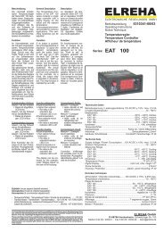
P09 .......Abtaubetriebsart<br />
1= zyklische Umluftabtauung, d.h. eine<br />
Abtauung wird immer nach Ablauf der<br />
mit P10 eingestellten Intervallzeit ausgelöst.<br />
Die Zeit beginnt mit dem Einschalten<br />
des Gerätes zu laufen.<br />
Ein<br />
Aus<br />
Abtauzyklus<br />
Abtaudauer<br />
Abtauung wird beendet<br />
Abtauung beginnt<br />
Parameter Explanation<br />
P01 .......Actual sensor temp. °C /°F (disp.only)<br />
*P02 .....Control Setpoint 1, no code necess.<br />
Affects to relay K1, range P04...P05<br />
P03 .......Switching hysteresis of P02<br />
range 2..20K resp. 4..36°F, [2K]<br />
P04 .......Highest adjustable Control Setpoint<br />
Range -50...+100°C (-58...212°F),<br />
affects to P02 only. [+100°C]<br />
P05 .......Lowest adjustable Control Setpoint<br />
Range -50°C/-58°F...P04. [-50°C]<br />
P06 .......Relay switching characteristic<br />
! Changeable with Code 70 only !<br />
Not available for <strong>TAR</strong> <strong>1180</strong> H<br />
• Cooling = Relay will be activated with<br />
rising temperature<br />
• Cooling relative = Relay will be activated<br />
with rising temperature, Setpoint 2<br />
(P13*) is an offset to P02.<br />
• Freezing = Relay will be de-activated<br />
with rising temperature<br />
• Heating = Relay will be activated with<br />
falling temperature<br />
• Heating relative = Relay will be activated<br />
with falling temperature, Setpoint<br />
2 (P13*) is an offset to P02.<br />
• Alarm active ON = Relay activated<br />
while alarm<br />
• Alarm active OFF = Relay de-activated<br />
while alarm. Cut-off point is<br />
always the setpoint.<br />
Relay K1 Relay K2<br />
01 ..........Cooling ............ Alarm active ON<br />
02 ..........Freezing .......... Alarm active ON<br />
03 ..........Heating ........... Alarm active ON<br />
11 ...........Cooling ............ Alarm active OFF<br />
12 ..........Freezing .......... Alarm active OFF<br />
13 ..........Heating ........... Alarm active OFF<br />
21 ..........Cooling ............ Defrost<br />
22 ..........Freezing .......... Defrost<br />
23 ..........Heating ........... Defrost<br />
31 ..........Cooling ............ Fan<br />
32 ..........Freezing .......... Fan<br />
33 ..........Heating ........... Fan<br />
41 ..........Cooling ............ Cooling<br />
42 ..........Freezing .......... Cooling<br />
43 ..........Heating ........... Cooling<br />
51 ..........Cooling ............ Heating<br />
52 ..........Freezing .......... Heating<br />
53 ..........Heating ........... Heating<br />
61 ..........Cooling ............ Cooling relative<br />
62 ..........Freezing .......... Cooling relative<br />
63 ..........Heating ........... Cooling relative<br />
71 ..........Cooling ............ Heating relative<br />
72 ..........Freezing .......... Heating relative<br />
73 ..........Heating ........... Heating relative<br />
P07 .......Display Mode / Sensor Type<br />
! Changeable with Code 70 only!<br />
0= TF201/°C, 1= TF201/°F<br />
2= TF202/°C, 3= TF202/°F, [0]<br />
P08 .......Sensor Correction<br />
Range ±10K or ±18F<br />
P09 .......Defrost Mode<br />
1= cyclic air defrost, this means a defrost<br />
cycle starts after the interval timer P10 is<br />
run down. This timer always starts with<br />
power-up of the unit.<br />
On<br />
Off<br />
Defrost cycle<br />
Defrost<br />
duration<br />
Defrost Off<br />
Defrost On<br />
Liste des paramètres<br />
P01 .......Valeur actuelle en °C /°F (Affi. seul)<br />
*P02 .....Consigne de régulation, limitation<br />
de la plage de réglage par P04 et P05<br />
P03 .......Différentiel de régulation<br />
Plage 2...20K. [2K]<br />
P04 .......Seuil haut consigne<br />
Plage -50...+100°C (-58..212°F)<br />
agit juste sur P02. [+100°C]<br />
P05 .......Seuil bas consigne<br />
Plage -50°C/-58°F...P04 [-50°C]<br />
P06 .......Comportement des relais<br />
! Réglable avec le code 70 !<br />
Ne pas disponible en <strong>TAR</strong> <strong>1180</strong> H<br />
• Réfrigérer = relais enclenche si la<br />
température augmente<br />
• Réfrigérer relatif = relais 2 enclenche<br />
si la température augmente selon P13*<br />
+ P02.<br />
• Congeler = relais déclenche si la<br />
température augmente<br />
• Chauffer = relais enclenche si la tem-<br />
pérature diminue<br />
• Chauffer relatif = relais 2 enclenche<br />
si la température diminue selon P13*<br />
+ P02.<br />
• Alarme active = relais 2 enclenche en<br />
cas d’alarme<br />
• Alarme passive = relais 2 déclenche<br />
en cas d’alarme.<br />
La coupure d’alarme est toujours le<br />
point de consigne.<br />
Relais K1 Relais K2<br />
01 ..........Réfrigérer ........ Alarme active<br />
02 ..........Congeler ......... Alarme active<br />
03 ..........Chauffer .......... Alarme active<br />
11 ...........Réfrigérer ........ Alarme passive<br />
12 ..........Congeler ......... Alarme passive<br />
13 ..........Chauffer .......... Alarme passive<br />
21 ..........Réfrigérer ........ Dégivrer<br />
22 ..........Congeler ......... Dégivrer<br />
23 ..........Chauffer .......... Dégivrer<br />
31 ..........Réfrigérer ........ Ventilateur<br />
32 ..........Congeler ......... Ventilateur<br />
33 ..........Chauffer .......... Ventilateur<br />
41 ..........Réfrigérer ........ Réfrigérer<br />
42 ..........Congeler ......... Réfrigérer<br />
43 ..........Chauffer .......... Réfrigérer<br />
51 ..........Réfrigérer ........ Chauffer<br />
52 ..........Congeler ......... Chauffer<br />
53 ..........Chauffer .......... Chauffer<br />
61 ..........Réfrigérer ........ Réfrigérer relatif<br />
62 ..........Congeler ......... Réfrigérer relatif<br />
63 ..........Chauffer .......... Réfrigérer relatif<br />
71 ..........Réfrigérer ........ Chauffer relatif<br />
72 ..........Congeler ......... Chauffer relatif<br />
73 ..........Chauffer .......... Chauffer relatif<br />
P07 .......Type d‘affichage / Sonde<br />
! Réglable avec le code 70 !<br />
0= TF201/°C, 1= TF201/°F<br />
2= TF202/°C, 3= TF202/°F, [0]<br />
P08 .......Correction d‘affichage<br />
Plage ±10K ou ±18F<br />
P09 .......Mode de dégivrage<br />
1= dégivrage cyclique naturel, signifie<br />
que le dégivrage s‘active toutes les pé-<br />
riodes P10.<br />
On<br />
Off<br />
Période P10<br />
Durée<br />
Dégiv.<br />
Dégivrage arrêté<br />
Dégivrage activé
2= Umluftabtauung nach Maschinenlaufz.<br />
Die Kühlrelais-Einschaltzeiten (1) werden<br />
addiert und gespeichert. Eine Abtauung<br />
startet, wenn die Gesamt-Einschaltzeit den<br />
mit P10 eingestellten Wert überschreitet.<br />
Danach wird der Zähler gelöscht.<br />
3= wie 1, jedoch mit Display Hold Funktion<br />
4 = wie 2, jedoch mit Display Hold Funktion<br />
(DH) Display Hold-Funktion<br />
Funktion um die Istwertanzeige während<br />
der Abtauphase ‘einzufrieren’. Während der<br />
Abtauung wird als Istwertanzeige der letzte<br />
Istwert vor Abtaubeginn angezeigt.<br />
Nach Ende der Abtauung beginnt die Messung<br />
wieder unter folgenden Voraussetzungen:<br />
• Der gemessenen Istwert wird kleiner als<br />
der Anzeigewert + 2K<br />
oder<br />
• Automatisch nach 15 Minuten<br />
Die „Display Hold“-Funktion wird mit den<br />
Abtaubetriebsarten (P09) 3 - 4 eingeschaltet.<br />
P10 ......Abtauzyklus / Maschinenlaufzeit<br />
Bereich 1...99 Stunden [4 Std.]<br />
P11 .......Abtaudauer<br />
0...99 Min., 0=keine Abtauung [15 Min.]<br />
Danach wieder Freigabe der Kühlung.<br />
Die Funktion der Parameter P12-P15<br />
hängt davon ab, ob Relais 2 als Alarmrelais<br />
oder Regelerelais konfigiert<br />
wurde.<br />
Hinweis Notice<br />
Relais 2 ist als Alarmrelais konfiguriert:<br />
P12 .....Obere Alarmtemperatur<br />
Bereich -50...+100°C [+26°C]<br />
P13 .....Untere Alarmtemperatur<br />
Bereich -50°C...P12 [-50°C]<br />
P14 .....Alarmverzögerung 1...99 min<br />
[60 Min.]<br />
P15 .....Alarmwiederholzeit nach<br />
. Quittierung<br />
. 0...99 Min., 0=kein weiterer Alarm<br />
. nach Quittierung [15 Min.]<br />
Relais 2 ist kein Alarmrelais:<br />
P12 .....keine Funktion<br />
P13 .....Sollwert 2, bzw. Schaltabstand zu P02<br />
P14 .....Hysterese von P13 (2-20K)<br />
P15 .....Ventilator-Nachlaufzeit<br />
Nach Ende der Kühlung, 0...99 Min<br />
P16 .......Mindest-Stillstandszeit Kühlung<br />
0...99 Min. [2 Min.]<br />
P17 .......Info: Restzeit bis nächste Abtauung<br />
P18 .......Info: Restlaufzeit aktuelle Abtauung<br />
P19 .......Info: Restlaufzeit Alarmverzögerung<br />
P20 .......Info: Mindeststillstandszeit<br />
*P21 Code zum Schutz gegen unautorisierte<br />
Bedienung, Standard-Codenummer ist<br />
-- 88 --, für P06 und P07 -- 70 --.<br />
Die mit „ * „ gekennzeichneten Parameter können ohne<br />
Code verstellt werden.<br />
Werte in Klammern [..] sind Werkseinstellungen.<br />
2= Air defrost depending on machine runt.<br />
All ON-times of the cooling relay (1) will be<br />
added and stored. A defrost starts, if the<br />
added ON-times exceed the value set by<br />
P10. Then the timer will be reset.<br />
3= like 1, but with Display Hold Function<br />
4= like 2, but with Display Hold Function<br />
(DH) Display Hold Function<br />
This function allows to hold the last measured<br />
actual temperature value on the display during<br />
a defrost cycle. After the defrost cycle has been<br />
terminated, the ‚Display Hold‘ ends when:<br />
• measured Actual Value falls short of the<br />
Display Value + 2K<br />
or<br />
• a fixed 15 minute timer has been run down<br />
The ‚DH‘-function can be used by setting the<br />
‚Defrost Modes‘ parameter P09 to 3 or 4.<br />
P10 ......Defrost Cycle / Machine Runtime<br />
range 1...99 hours [4 h]<br />
P11 .......Defrost Duration<br />
0...99 min., 0=no defrost [15 min.]<br />
After that, cooling restarts.<br />
The function of the parameters P12-P15<br />
depends on the configuration of relay 2<br />
(control relay or alarm relay).<br />
Relay 2 is configured as alarm relay:<br />
P12 .....Upper Alarm Temperature<br />
Range -50...+100°C [+26°C]<br />
P13 .....Lower Alarm Temperature<br />
Range -50°C...P12 [-50°C]<br />
P14 .....Alarm Delay 1...99 min [60 Min.]<br />
P15 .....Alarm Repeat Time after Reset<br />
0...99 min., 0=no further alarm after<br />
reset [15 Min.]<br />
Relay 2 ist no Alarmrelais:<br />
P12 .....no function<br />
P13 .....Control Setpoint 2, resp. Offset to P02<br />
P14 .....Switching hysteresis of P13 (2-20K)<br />
P15 .....Fan trailing time<br />
After cooling, 0...99 min<br />
P16 .......Minimum Refrigeration Idle Time<br />
0...99 min. [2 Min.]<br />
P17 .......Info: Remaining time till next defrost<br />
P18 .......Info: Rem. time actual defrost cycle<br />
P19 .......Info: Remaining time alarm delay<br />
P20 .......Info: Remain. refrigeration idle time<br />
*P21 .....Access Code, protection against<br />
unauthorized access, standard code<br />
is -- 88 --, for P06 and P07 -- 70 --.<br />
The marked „ * „ parameters can be set without access<br />
code.<br />
Values in brackets [..] are factory set.<br />
2= Dégivrage naturel selon durée de<br />
réfrigération.<br />
Tous les temps de réfrigération sont additionnés.<br />
Le dégivrage s‘active lorsque la<br />
durée totale atteint le temps P10. Après un<br />
dégivrage, le compteur se remet à zéro.<br />
3= comme 1, mais avec Disp.Hold Function<br />
4= comme 2, mais avec Disp.Hold Function<br />
(AF) Affichage figé<br />
Fonction permettant de „figer“ l’affichage pendant<br />
la phase de dégivrage : l’afficheur indique ainsi<br />
la mesure effectuée juste avant le dégivrage. A<br />
la fin du dégivrage, la mesure recommence à<br />
s’afficher selon les critères suivants :<br />
• La mesure actuelle est inférieure à la valeur<br />
affichée au dégivrage + 2K<br />
ou<br />
• Automatiquement après 15 minutes<br />
P10 ......Dégivrage : Période / Durée réfr.<br />
Plage 1...99 heures [4 h]<br />
P11 .......Durée de dégivrage<br />
0...99 min., 0=désactivé [15 min.]<br />
Après, la réfrigération se remet en route<br />
Avis<br />
La fonction des paramètres P12 à P15<br />
dépend de la configuration du relais 2<br />
(relais de régul. ou d’alarme).<br />
Relais 2 configuré comme alarme:<br />
P12 .......Seuil haut d‘alarme t°C<br />
Plage -50...+100°C [+26°C]<br />
P13 .......Seuil bas alarme t°C<br />
Plage -50°C...P12 [-50°C]<br />
P14 .......Retard d‘alarme 1...99 min [60 min]<br />
P15 .......Retard d‘alarme après acquit.<br />
0...99 min., 0= plus d‘alarme après ac-<br />
quittement [15 min]<br />
Relais 2 non configuré comme alarme:<br />
P12 ......aucune fonction<br />
P13 Consigne 2 ou selon le cas écart<br />
par rapport à la consigne P02<br />
P14 .....Hystérésis de P13 (2-20K)<br />
P15 .....Retard arrêt ventilation<br />
A l’arrêt du froid , 0...99 Min<br />
P16 .......Anti-court cycle réfrigération<br />
0...99 min. [2 Min.]<br />
P17 .......Affichage temps avant prochain dég.<br />
P18 .......Affichage temps avant fin dég. actuel<br />
P19 .......Affichage temps avant alarme<br />
P20 .......Affichage temps anti-court cycle<br />
*P21 .....Entrée code déverrouillage,<br />
code standard est -- 88 --,<br />
pour P06 et P07 -- 70 --.<br />
Les paramètres précédés du signe „ * „ peuvent être<br />
modifiés sans déverrouiller l‘appareil.<br />
Valeurs [..] sont les valeurs d’usine.
Funktion<br />
Die mit einem Fühler gemessene Temperatur wird<br />
von einem Mikrocontroller verarbeitet und angezeigt.<br />
Nach einem Istwert-/Sollwertvergleich werden dann<br />
entsprechend der Konfiguration die Ausgangsrelais<br />
geschaltet.<br />
Fühler und Anzeige<br />
Es können 2 verschiedene Fühlertypen verwendet und<br />
Werte wahlweise als °C oder °F angezeigt werden,<br />
umschaltbar mit P07.<br />
Relaiskonfiguration<br />
Beide Ausgangsrelais können mit P06 für unterschiedliche<br />
Aufgaben konfiguriert werden. (Siehe<br />
Parameterliste, Code 70 notwendig).<br />
Temperaturalarm<br />
Verlässt der gemessene Istwert voreingestellte<br />
Grenzwerte (P12/P13), dann kann ein Alarm ausgelöst<br />
und mit Relais K2 als Warnrelais weitergegeben<br />
werden.<br />
Alarm Quittieren, siehe Seite 1<br />
Abtauung<br />
Die Abtauung wird durch einen Zyklustimer gestartet.<br />
Während der Abtauung bleibt die Kühlung gesperrt.<br />
Die erste Abtauung nach dem Einschalten erfolgt<br />
nach der mit P10 festgelegten Zeit. Steht P11 auf<br />
„0“ ist die Abtaufunktion abgeschaltet. Relais K2<br />
kann wahlweise als Abtaurelais zum Schalten einer<br />
Heizung konfiguriert werden.<br />
Hinweis Spezialfunktion: Ist Relais 1 für Heizen und<br />
Relais 2 für Abtauen konfiguriert, wird die Heizung<br />
während einer Abtauphase gesperrt.<br />
Abtauung manuell EIN / AUS, siehe Seite 1<br />
Ventilatorsteuerung<br />
Ist Relais K2 als Ventilatorrelais konfiguriert, so<br />
schaltet dieses zusammen mit der Kühlung und mit<br />
der Abtauung. Nach Ende der Kühlung bleibt das<br />
Ventilatorrelais noch für die mit P15 eingestellte Zeit<br />
angezogen (Nachlaufzeit).<br />
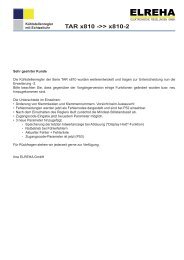
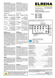
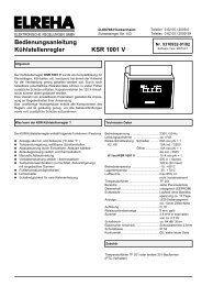
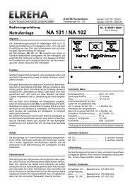
Anwendungsbeispiel<br />
<strong>TAR</strong> <strong>1180</strong>,<br />
Relais K1 konfiguriert für Kühlung,<br />
Relais K2 konfiguriert für Warnung<br />
Application Example<br />
<strong>TAR</strong> <strong>1180</strong>,<br />
Relay K1 configured for cooling,<br />
Relay K2 configured for alarm<br />
Exemple d’application<br />
<strong>TAR</strong> <strong>1180</strong>,<br />
Relais K1 configuré en réfrigérer,<br />
Relais K2 configuré en alarme<br />
Function<br />
The controller measures the actual temperature with<br />
a temperature probe. This value is compared with<br />
control setpoints and according to result and the<br />
relays configuration they switch ON or OFF.<br />
Sensor and Display<br />
The controller is able to operate with 2 different<br />
sensor types, the value can be displayed as °C or<br />
°F, presettable by P07.<br />
Relay Configuration<br />
Both output relays can be configured for different<br />
tasks by P06. (See Parameter Listing, Code 70<br />
necessary)<br />
Temperature Alarm<br />
If the measured temperature leaves a predefined<br />
range (P12/P13), then an alarm can be forwarded<br />
by relay K2 configured as an alarm relay.<br />
Alarm Reset, see page 1<br />
Defrost<br />
A defrost event is started by a cyclic timer. During the<br />
defrost cycle, cooling remains disabled. The first defrost<br />
event after power-up will start after the time set<br />
by P10. When P11 is set to „0“, the defrost function<br />
is disabled. Relay K2 can be configured as a defrost<br />
relay, e.g. to switch a defrost heater.<br />
Special function note: If relay K1 is configured for<br />
heating and relay K2 for defrost, the heating will be<br />
disabled during a defrost cycle.<br />
Fonction<br />
Le micro-contrôleur affiche la mesure effectuée par<br />
la sonde de température. Selon la différence entre la<br />
mesure et la consigne, le relais de sortie commute en<br />
fonction du comportement de régulation configuré.<br />
Sonde et affichage<br />
L’appareil accepte les 2 types de sonde PTC et<br />
l’affichage s’effectue en °C ou °F, réglage en P07.<br />
Configuration des relais<br />
P06 permet de configurer la fonction des 2 relais de<br />
sortie. (voir liste des paramètres, Code „70“).<br />
Alarme de température<br />
Si la mesure sort de la plage définie par les seuils P12<br />
et P13, l’alarme se déclenche et le relais K2 permet<br />
d’annoncer les défauts s’il est configuré comme relais<br />
d’alarme.<br />
Acquittement alarme, voir page 1<br />
Dégivrage<br />
Le dégivrage démarre selon un compteur cyclique.<br />
Durant le dégivrage, le relais de froid reste bloqué.<br />
A la mise en route, le premier dégivrage démarre<br />
à la fin du temps P10. Si P11 est réglé sur „0“, le<br />
dégivrage est inhibé. Le relais K2 peut être configuré<br />
sur „dégivrer“, pour commander une résistance de<br />
dégivrage par exemple.<br />
Nota fonction spéciale : si le relais 1 travaille en chauffage<br />
et le relais 2 comme dégivrage, le chauffage sera<br />
coupé au dégivrage.<br />
Defrost manually ON / OFF, see page 1<br />
Fan Control<br />
Dégivrage manuel ON / OFF, voir page 1<br />
If relay K2 is configured as a fan relay, it switches<br />
in parallel to cooling and defrost. After the end of Gestion de la ventilation<br />
cooling, the fan relay remains ON for the time preset Si le relais K2 est configuré comme „Ventilateur“, le<br />
by P15 (trailing time).<br />
relais commandera la ventilation à la réfrigération et<br />
au dégivrage. Lorsque la réfrigération se coupe, le<br />
ventilateur fonctionne encore durant le temps réglé<br />
P15 (Retard d’arrêt).<br />
12 V<br />
AC/DC<br />
1 2 3 4 5 6 7 8 9 10 11 12<br />
Kühlstelle<br />
Poste de froid<br />
cold storage<br />
Regelfühler<br />
Sonde régulation<br />
Sensor
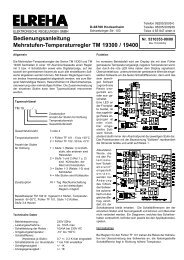
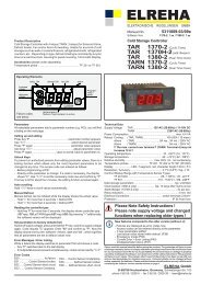
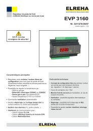
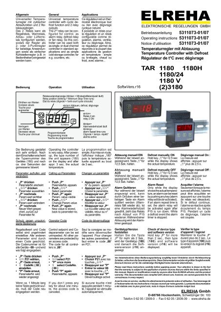
Maßbilder / Dimensions Series <strong>TAR</strong> <strong>1180</strong><br />
1 2<br />
<strong>TAR</strong><br />
76 (3.0)<br />
ELREHA<br />
Rückansicht Rückansicht mit Befestigungsrahmen<br />
Befestigungsrahmen<br />
rear view with withmounting mouning frame<br />
1 2 3 4 5 6 7<br />
28 (1.1)<br />
Maßbilder / Dimensions Series <strong>TAR</strong> <strong>3180</strong><br />
8<br />
75 (2.95)<br />
70 (2.76)<br />
46 (1.81)<br />
58 (2.28)<br />
30 (1.18)<br />
3<br />
9 10 11 12<br />
Ausschnitt<br />
cut-out<br />
anehmbar<br />
removable<br />
P 35 (1.38)<br />
37 (1.46)<br />
1<br />
2<br />
3<br />
4<br />
5<br />
6<br />
7<br />
8<br />
9<br />
10<br />
70 (2.76)<br />
Tür/Panel<br />
10 11 12 13 14 15 16 17 18<br />
1<br />
1<br />
2<br />
2<br />
3<br />
51.5 (2.02)<br />
P<br />
ELREHA<br />
3 4 5 6 7 8 9<br />
1<br />
2<br />
3<br />
4<br />
5<br />
6<br />
7<br />
8<br />
9<br />
10<br />
11<br />
12<br />
12 V<br />
AC/DC<br />
56 (2.2)<br />
K1<br />
K2<br />
Temperaturregler<br />
ELREHA<br />
3 (.12)<br />
<strong>TAR</strong> <strong>1180</strong> - <strong>1180</strong>/<strong>24</strong> <strong>TAR</strong> <strong>1180</strong> V<br />
Dichtung/<br />
gasket<br />
46.5 (1.83)<br />
60 (2.36)<br />
87.5 (3.45)<br />
28 (1.1)<br />
10 11<br />
Netz<br />
Mains<br />
4<br />
1<br />
2<br />
3<br />
4<br />
5<br />
6<br />
7<br />
8 12 V<br />
AC/DC<br />
9<br />
10<br />
11<br />
12<br />
<strong>TAR</strong> <strong>3180</strong><br />
K2<br />
5<br />
K1<br />
K2<br />
Temperaturregler<br />
K1<br />
ELREHA<br />
17 18<br />
6 7 8 9
Installation / Inbetriebnahme<br />
Achtung !<br />
• Der elektrische Anschluss und die<br />
Inbetriebnahme muss durch eine<br />
Gefahr<br />
Elektrofachkraft erfolgen.<br />
• Die einschlägigen örtlichen Sicherheitsvorschriften<br />
sind zu beachten.<br />
• Anschlusswerte gemäß Typenschild<br />
beachten.<br />
Die Fühlerleitungen müssen bei Verlängerung<br />
abgeschirmt sein und dürfen nicht parallel zu netzspannungsführenden<br />
Leitungen verlegt werden. Die<br />
Abschirmung ist einseitig zu erden.<br />
Der Querschnitt der Fühlerkabel ist auch bei Verlängerung<br />
unkritisch, Querschnitte ab 0,5mm² sind<br />
ausreichend. Nach Einschalten des Reglers zeigt<br />
das Display den gemessenen Istwert.<br />
Nachdem Sie wie beschrieben die Codenummer<br />
eingegeben haben, können Sie die Konfiguration<br />
des Reglers festlegen:<br />
• Relaisschaltverhalten mit P06<br />
• Anzeige/Fühlertyp mit P07.<br />
• Korrekturwert für die Anzeige (bei Bedarf)mit<br />
"P08".<br />
• Sollwertbereich (nach Bedarf) mit P04/P05<br />
Danach können die gewünschten Sollwerte festgelegt<br />
werden. Informationen über laufende Verzögerungszeit<br />
liefern die Parameter P17 bis P20.<br />
Fehleranzeigen<br />
Display blinkt -> Anzeige -60 = Fühlerkurzschluß<br />
Display blinkt -> Anzeige 110 = Fühlerbruch<br />
Bei Fühlerbruch bzw. Fühlerkurzschluß (oder außerhalb<br />
-60/+110°C) wird die Kühlung nach 1 Minute<br />
ausgeschaltet und eine Alarm unabhängig von der<br />
Alarmverzögerungszeit (P14) ausgelöst.<br />
Technische Daten<br />
Betriebsspannung .........12V AC/DC (12-18VDC)<br />
<strong>TAR</strong> <strong>1180</strong>/<strong>24</strong> ..................................<strong>24</strong>V AC/DC<br />
<strong>TAR</strong> <strong>3180</strong> ...........................................230V AC<br />
Leistungsaufnahme ............................. max. 4 VA<br />
Relais-Schaltleistung .......................8A cos phi=1<br />
3A induktiv / 250V~<br />
<strong>TAR</strong> <strong>1180</strong> V ...............12A Nennstrom, 250V~<br />
Betriebstemperatur ............................-10...+55°C<br />
Lagertemperatur ................................-20...+60°C<br />
Temperaturbereich...........................-50...+100°C<br />
Auflösung........................................................1 K<br />
Display ........................................LED, rot, 13mm<br />
Relaisanzeige ....................................1,2 mm, rot<br />
Anschluß...........................Schraubklem. 2,5mm²<br />
Schutzklasse .............................. IP 54 von vorne<br />
<strong>TAR</strong> <strong>3180</strong> .................................................IP 30<br />
Werkseinstellungen laden<br />
Taste „P“ beim Einschalten<br />
halten, folgende Informationen<br />
erscheinen: „180“-“rxx“-<br />
“def“ (Gerätetyp, Revision,<br />
Default). Damit sind die Werlseinstellungen<br />
geladen.<br />
Load Default values<br />
Push and hold „P“ while power-up,<br />
the following informations<br />
appear: „180“-“rxx“-“def“<br />
(type of unit, revision, default).<br />
Now the controller is reset to<br />
default values.<br />
Installation<br />
Precautions !<br />
• Electrical installation and putting<br />
into service must be done from<br />
authorized personnel.<br />
• Please note the local safety<br />
instructions and standards!<br />
• Please note the maximum ratings !<br />
If you have to lengthen the sensor cables, use a<br />
shielded type with one end of the shield connected<br />
to ground. This minimizes the effect of irregular switching<br />
events caused by electromagnetic interference.<br />
The sensor leads may be up to hundred meters long.<br />
Any wire size from 0.5 mm² up can be used.<br />
After the power has been switched on, the controller<br />
will display the actual sensor temperature.<br />
After programming the access code, you can set the<br />
configuration according to the application.<br />
• Set relay action with P06<br />
• Set display mode / sensor type with P07.<br />
• Corrective value for the actual display (if<br />
necessary) with parameter "P08".<br />
• Set setpoint range with P04/P05 if necessary.<br />
Now the desired control setpoints can be entered.<br />
Informations about running timers you will find at<br />
P17-P20.<br />
Failure Display<br />
Display flashing -> value -60 = sensor short<br />
Display flashing -> value 110 = sensor broken<br />
If the controller detects a broken or shorted sensor,<br />
(or temp. is not within -60/+110°C) cooling will be<br />
switched off after 1 minute. An alarm will be generated<br />
independent from the set delay P14.<br />
Technical Data<br />
Supply Voltage.................12V AC/DC (12-18VDC)<br />
<strong>TAR</strong> <strong>1180</strong>/<strong>24</strong> ..................................<strong>24</strong>V AC/DC<br />
<strong>TAR</strong> <strong>3180</strong> ........................................230V AC<br />
<strong>TAR</strong> 2<strong>3180</strong> ........................................ 115V AC<br />
Power consumption ............................. max. 4 VA<br />
Relay Rating ....... 8A cos phi=1, 1/4 HP / 250V~<br />
<strong>TAR</strong> <strong>1180</strong> V ....................12A nominal, 250V~<br />
Temp. Range working ........................-10...+55°C<br />
storage ........................-20...+60°C<br />
Display/Control Range.....................-50...+100°C<br />
Resolution........................................................1K<br />
Display .............................................LED red 1/2“<br />
Relay position indicator ..................... 1,2 mm red<br />
Screw terminals .......................................2,5mm²<br />
Protection class .......................... IP 54 from front<br />
<strong>TAR</strong> <strong>3180</strong> ..............................................IP 30<br />
Remettre les valeurs<br />
d‘usine<br />
En appuyant sur la touche<br />
„P“ de façon continue,<br />
les informations suivantes<br />
apparaissent: „180“-“rxx“-<br />
“def“ (type, version, def<br />
(usine). En relâchant la<br />
touche, les valeurs d‘usine<br />
sont réglées.<br />
Installation<br />
Attention !<br />
• La mise en route et le raccordement<br />
électrique ne sont permis qu‘aux des<br />
personnes qualifiées.<br />
• Lors du montage de l‘alimentation,<br />
respecter les mesures de sécurité<br />
prévues.<br />
• Respecter les données techniques.<br />
Pour éviter des problèmes à cause d’un courant<br />
induit il est nécessaire que le câble de la sonde soit<br />
du type blindé et qu’il ne soit pas installé en parallèle<br />
avec des câbles de puissance.<br />
Le blindage doit être branché à la terre d’un côté<br />
seulement. La section du câble n‘est pas critique,<br />
même s‘il est rallongé. Une section à partir de 0,5mm²<br />
est suffisante. Après la mise sous tension I’afficheur<br />
indique la température actuelle.<br />
Après avoir entré le code de déverrouillage comme<br />
indiqué précédemment, vous pouvez configurer le<br />
régulateur:<br />
• Comportement du relais en P06,<br />
• Type d'affichage / Sonde en P07,<br />
• Correction d'affichage (si nécessaire) en P08,<br />
• Limitation de la plage de consigne en P04 et P05<br />
Maintenant il vous reste à régler les différentes<br />
consignes. Les paramètres P17 à P20 sont des<br />
valeurs d'affichages.<br />
Affichage d‘un défaut<br />
En cas de coupure ou de court-circuit de sonde (ou<br />
dépassement des seuils -60/+110°C), l‘afficheur<br />
clignote, l‘alarme s‘active immédiatement et la réfrigération<br />
s‘arrête au bout d‘une minute.<br />
L‘afficheur clignote et indique -60 = Court-circuit<br />
L‘afficheur clignote et indique 110 = Coupure<br />
Caractéristiques techniques:<br />
Temperaturfühler, Sensors, Sondes<br />
Tension d’alimentation .....12V AC/DC (12-18VDC)<br />
<strong>TAR</strong> <strong>1180</strong>/<strong>24</strong> ..................................<strong>24</strong>V AC/DC<br />
<strong>TAR</strong> <strong>3180</strong> ...........................................230V AC<br />
Consommation .................................... 4 VA max.<br />
Puissance du relais .........................8A cos phi=1<br />
3A ind. / 250V~<br />
<strong>TAR</strong> <strong>1180</strong> V .......12A courant nominal, 250V~<br />
T°C de fonctionnement ..................-10°C...+55°C<br />
T°C de stockage ............................-20°C...+60°C<br />
Plage de régulation .........................-50...+100°C<br />
Résolution........................................................1K<br />
Affichage........................... 7 segm. rouge, 13mm<br />
Indicateur état du relais ......... LED rouge, 1,2mm<br />
Bornier .....................................................2,5mm²<br />
Classe de protection ................... IP 54 de façade<br />
<strong>TAR</strong> <strong>3180</strong> .................................................IP 30<br />
Temperature -20°C -10°C 0°C +10°C +20°C +25°C<br />
TF 201 1366 1493 1628 1771 1922 2000<br />
TF 202 683 746,5 814 885,5 961 1000<br />
Resistance (Ohms)<br />
For all described products there is a declaration of conformity which describes that, when operated in accordance with the technical manual, the<br />
criteria have been met that are outlined in the guidelines of the council for alignment of statutory orders of the member states on EMC-Directive<br />
(2004/108/EC) and the Low Voltage Directive (LVD 2006/95/EC). This declarations are valid for those products covered by the technical manual<br />
which itself is part of the declaration. To meet the requirements, the currently valid versions of the relevant standards have been used.<br />
This statement is made from the manufacturer / importer by:<br />
EG-Conformity<br />
ELREHA Elektronische Regelungen GmbH Werner Roemer, Technical Director<br />
D-68766 Hockenheim<br />
www.elreha.de Hockenheim.............6.11.2008.......................................................<br />
(name / adress) city date sign<br />
original set up: 14.5.09, tkd/jr checked: 19.5.09, kd/mh approved: 19.5.09, mkt/sha transl.(E): 14.5.09, tkd/jr transl(F)..ef/tn